

Page 1
3
B
SERVICE MANUAL
COLOUR TELEVISION
AV-20N3/AV-20N3
AV-20NMG3/AV-20NMG3B
/D
AV-20N3
AV-20NMG
AV-20NMG3
BASIC CHASSIS
CG
/AV-20NMG3
[
RM-C 36 4G Y ]
[ RM-C364 ]
CONTENTS
/-A
!
SPECIFICATIONS
!
SAFETY PRECAUT IONS ・・・・・・・・・・・・・・・・・・・・・・・・・・・・・・・・
! FEATU RES・・・・・・・・・・・・・・・・・・・・・・・・・・・・・・・・
! FUNCTIONS ・・・・・・・・・・・・・・・・・・・・・・・・・・・・・・・・
!
MAIN DIFFERENCE LIST ・・・・・・・・・・・・・・・・・・・・・・・・・・・・・・・・
! SPECIFIC SERVICE INSTRUCTIONS ・・・・・・・・・・・・・・・・・・・・・・・・・・・・・・・・
!
SERVICE ADJUSTMENTS
!
PARTS LIST ・・・・・・・・・・・・・・・・・・・・・・・・・・・・・・・・
★ OPERAT ING INSTRUCTIONS
★ STAND ARD CIRCUIT DIAGRAM ・・・・・・・・・・・・・・・・・・・・・・・・・・・・・・・・
1
・・・・・・・・・・・・・・・・・・・・・・・・・・・・・・・・・・・・・・・・・・・・・・・・・・・・・・・・・・・・・・・・
・・・・・・・・・・・・・・・・・・・・・・・・・・・・・・・・・・・・・・・・・・・・・・・・・・・・・・・・・・・・・・・・
・・・・・・・・・・・・・・・・・・・・・・・・・・・・・・・・
・・・・・・・・・・・・・・・・・・・・・・・・・・・・・・・・・・・・・・・・・・・・・・・・・・・・・・・・・・・・・
・・・・・・・・・・・・・・・・・・・・・・・・・・・・・・・・・・・・・・・・・・・・・・・・・・・・・・・・・・・・・・・・
・・・・・・・・・・・・・・・・・・・・・・・・・・・・・・・・・・・・・・・・・・・・・・・・・・・・・・・
・・・・・・・・・・・・・・・・・・・・・・・・・・・・・・・・・・・・・・・・・・・・・・・・・・・・・・・・・・・・・・・・
・・・・・・・・・・・・・・・・・・・・・・・・・・・・・・・・・・・
・・・・・・・・・・・・・・・・・・・・・・・・・・・・・・・・・・・・・・・・・・・・・・・・・・・・・・・・・・・・・・・・
・・・・・・・・・・・・・・・・・・・・・・・・・・・・・・・・・・・・・・・・・・・・・・・・・・・・・・・・・・・・・・・・
・・・・・・・・・・・・・・・・・・・・・・・・・・・・・・・・・・・・・・・・・・・・・・・・・・・・・・・・・・・・・・・・
・・・・・・・・・・・・・・・・・・・・・・・・・・・・・・・・・・・・・・・・・・・・・・・・・・・・・・・
・・・・・・・・・・・・・・・・・・・・・・・・・・・・・・・・・・・・・・・・・・・・・・・・・・・・・・・・・・・・・・・・
・・・・・・・・・・・・・・・・・・・・・・・・・・・・・・・・・・・・・・・・・・・・・
・・・・・・・・・・・・・・・・・・・・・・・・・・・・・・・・・・・・・・・・・・・・・・・・・・・・・・・・・・・・・・・・
・・・・・・・・・・・・・・・・・・・・・・・・・・・・・・・・
・・・・・・・・・・・・・・・・・・・・・・・・・・・・・・・・・・・・・・・・・・・・・・・・・・・・・
・・・・・・・・・・・・・・・・・・・・・・・・・・・・・・・・・・・・・・・・・・・・・・・・・・・・・・・・・・・・・・・・
・・・・・・・・・・・・・・・・・・・・・・・・・・・・・・・・・・・・・・・・・・・・・・・・・・・・・・・・・・・・・・・・
・・・・・・・・・・・・・・・・・・・・・・・・・・・・・・・・・・・・・・・・・・・・・・・・・・・・・・・・・・・・・・・・
・・・・・・・・・・・・・・・・・・・・・・・・・・・・・・・・・・・・・・・・・・・・・・・・
・・・・・・・・・・・・・・・・・・・・・・・・・・・・・・・・・・・・・・・・・・・・・・・・・・・・・・・・・・・・・・・・
COPYRIGHT © 2002 VICTOR COMPANY OF JAPAN, LTD.
・・・・・・・・・・・・・・・・・・・・・・・・・・・・・
・・・・・・・・・・・・・・・・・・・・・・・・・・・・・・・・・・・・・・・・・・・・・・・・・・・・・・・・・・
・・・・・・・・・・・・・・・・・・・・・・・ 3
・・・・・・・・・・・・・・・・・・・・・・・・・・・・・・・・・・・・・・・・・・・・・・
・・・・・・・・・・・・・・・・・・・・・・・・・・・・・・・・・・
・・・・・・・・・・・・・・・・・・・・・・・・・・・・・・・・・・・・・・・・・・・・・・・・・・・・・・・・・・・・・・・・
・・・・・・・・・・・・・・・・・・・・・・・ 7
・・・・・・・・・・・・・・・・・・・・・・・・・・・・・・・・・・・・・・・・・・・・・・
・・・・・・・・・・・・・・・・・・・・・
・・・・・・・・・・・・・・・・・・・・・・・・・・・・・・・・・・・・・・・・・・
・・・・・・・・・・・・・・・・・・・・・・・・・・・・・・・・・・・・ 33
・・・・・・・・・・・・・・・・・・・・・・・・・・・・・・・・・・・・・・・・・・・・・・・・・・・・・・・・・・・・・・・・
・・・ 4
・・・・・・
・・ 5
・・・・
・・・・・・・・・・・・・ 8
・・・・・・・・・・・・・・・・・・・・・・・・・・
15
・・・・・・・・・・・・・・・・2-1
・・・・・・・・・・・・・・・・・・・・・・・・・・・・・・・・
2
No. 52025
Jun. 2002
Page 2
A
V-20N3
A
A
V-20NMG3
V-20NMG3B
SPECIFICATIONS
CONT ENTS
ITEM
Dimen sions( W×H×D) 619mm×458mm×488mm
Mass
TV RF Syst em B/ G, I, D/K B/ G, I, D/K, M
19kg
AV - 20 N3
AV - 20 N3
/D
AV-20NMG3
AV-20NMG3B
AV-20NMG3
/-A
Colour System
Pi ctur e Tube
High Voltage 26.5kV±1.5kV(at zero beam current)
Receiving Frequency
Intermediate
Frequen cy
Col ou r S ub C arr ier Fr e q uen cy
Power Input Rated Voltage
Power Co nsumpti on
RF Mode PAL / SECAM PAL / SECAM / NTSC3.58 / NTSC4.43
VIDEO Mode PAL / SECAM / NTSC3.58 / NTSC4.43
Visible size: 48cm measured diagonally
VHF (VL) 46.25MHz~168.25MHz
VHF (VH) 175.25MHz~463.25MHz
UHF 471.25MHz~863.25MHz
Cable TVs of Mid ( X-Z, S1-S10)
CATV
VIF Carrier 38.0MHz
SIF Carrier
Super (S11-S20) & Hyper (S21-S41)
bands recei vable
32.5MHz (5.5MHz)
31.5MHz (6.5MHz)
32.0MHz
PAL (4.43MHz),
SECAM (4.40625MHz / 4.25MHz)
NTSC (3.58MHz / 4.43MHz)
AC110~240V, 50 / 6 0Hz
90W (Max) / 60W(Avg)
(6.0MHz)
32.5MHz(5.5MHz) /33.5MHz (4.5MHz)
31.5MHz (6.5MHz)
32.0MHz
(6.0MHz)
Speaker
Audio Output
Aer ial In pu t Termi n al
Input
Output
Headphone jack
Remote Control Unit
Video 1V(p-p), 75Ω (Front / Rear )
Audio
Video 1V(p-p), 75
Audio 500mV(rms) (-4dBs), Low impedance,
5cm×12 cm, Oval type×2
3W (monaural )
75Ω Unbalanced
500mV(rms) (-4dBs), High impedance,
RCA×2 (Front / Rear)
Ω
3.5mm mini jack
RM-C364GY
(Batter y size : AA / R06 / UM- 3×2)
Design and specifications are subject to change without notice.
2
No. 52025
[AV-20NMG3 / AV-20NMG3
: RM-C364G Y
[AV-20NMG3B]
: RM-C364
(Batter y size : AA / R06 / UM- 3×2)
/-A]
Page 3
A
3
A
A
SAFETY PRECAUTIONS
V-20N
V-20NMG3
V-20NMG3B
1. The d es ign of th is prod uct c on ta ins sp eci al har d wa re , many
circuit s and components specially for safety purp oses. For
con tinu ed pr ot ection , n o c han g es sh ou ld b e ma de to the o ri g i nal
d esi gn un less auth or ized in w riti n g by th e ma nu fact urer.
Replacem en t par ts must b e id ent ic al to thos e u sed in th e or i gi n al
ci rcu its. Servi ce sho ul d b e per formed by qu alif ied p ers on nel
on ly.
2. Al te rati on s of t he des i g n or circui tr y of t he pr od ucts s h oul d not be
made. Any design alterations or additions will void the
manu fact ur er 's warrant y and w ill f urth er r el i eve t he manu factu rer
of r esp onsi b ility for perso na l injury or pr op erty dam ag e r es ult in g
th erefr om.
3. M an y electr i c al an d m ech anic a l p ar ts in th e prod ucts ha ve
special safety-related characteristics. These characteristics are
oft en not e v iden t f rom vi sual insp ec ti on n or c a n t he pro tec t io n
aff or de d by th em nec e ssar i l y be ob tai n ed b y u sing rep lacem en t
com po ne nts ra ted f or hig he r voltag e, w att ag e, etc. Rep lacem en t
p arts whic h ha ve th ese sp eci al s afet y charact erist ics ar e
ide ntified i n the parts li st of S ervice manual. El ectric al
components having such features are ide ntified by shading
on t h e sche mat ics and by (!!!! ) on the parts list in Service
manual. T he us e of a sub sti tu te rep lacem en t whic h do es n ot
h ave th e s ame saf ety ch ar act erist ics as t he reco mm en de d
replac em ent part sh own i n th e parts li st of Ser v ice m an ual m ay
cause shock, fire, or other hazards .
4. Don't shor t between the LIVE side ground and ISOLATED
(NE UTRAL) side ground or EARTH side ground when
repairing.
Some model's power circuit is partly different in the GND. The
diff er enc e of th e GND is s ho wn b y th e LIV E : ( ") side GN D, the
ISO LATE D(N EUTRAL) : (#) si de GND and EARTH : ( $) side
GND. Do n't s h or t bet we en th e LIV E sid e GN D an d
ISO LATE D(N EUTRAL) side GND or EART H side GND an d
n ever m ea sur e w it h a mea sur ing a ppa ratus ( os cil lo scop e etc.)
th e LI VE si d e GND an d IS OLA TED(N E UTRAL ) sid e G ND or
EARTH side GND at the s ame time.
If above not e will not be kept, a fuse or any parts will be broken.
5. If any repair has been made to the chassis, it is recommended
th at t he B1 set ting shou l d b e c h ecke d or adj u ste d ( See
ADJUST M ENT OF B 1 POW E R SUPPL Y).
6. The high vol tage app lie d t o th e pictu r e tu be mus t c on for m w it h
th at s p ec ifi ed i n S er v ice m an ual. E xcess ive h igh vo lt ag e ca n
cau s e an i ncre ase in X-Ray em i ssi on , ar c i ng an d possib le
component damage, therefore operation under excessive high
voltage conditions should be kept to a minimum, or should be
preve nt ed. If s ever e arc ing occur s, r em ove t he AC power
immed i ate ly and de termine th e cause b y visua l insp ect ion
(inc or r ect install at ion, cr ac ke d or mel te d high vo lt age har n ess,
p oor so lder i ng, et c.) . T o m ai nt ain the p r ope r mi n im u m le vel of
sof t X- R ay emis si on, c omp on ents in th e high voltag e cir c uitr y
incl ud i ng t he pict ur e tube must b e t he exac t r ep l aceme nts or
alte rn at ives ap prov e d b y th e manuf act ur er of th e c omplet e
prod uct.
7. Do n ot c hec k high volt ag e b y dr awing an ar c. U se a hi gh volt age
meter or a hi g h v ol tag e probe wit h a V TVM . Di s cha rge th e
picture tube before attempting meter connection, by connecting
a cl i p lead to the grou nd frame a nd conn ectin g th e oth er end of
the lead through a 10kΩ 2W resi sto r to the an od e butt on .
8. W hen service i s r equ ire d, ob ser ve th e or igina l lea d dres s. E x tr a
prec aut ion sh ou ld b e given t o assure correct l ea d dress in th e
high vol tag e ci r cui t a r ea. W her e a s hor t circui t h as occ u rr e d,
th ose co mpon ent s tha t i ndi ca te ev ide nce of ove r hea ting sho ul d
b e r e pl ace d. A lwa ys use th e ma nuf act urer's r ep l acemen t
components.
9. Isolation Check
(Safety for Electrical Shock Hazard)
Af ter re-ass emb ling th e pr odu c t, alw ays per f orm an i solat io n
ch ec k on the ex po sed me tal p ar ts of t he c abin et ( a nte nn a
ter m ina ls, video /au dio inpu t and ou tput t erminals, C on trol kn obs,
metal cabin et, s cr ew he ads, ea rph one jack, c on tr ol shaf ts, etc.)
to be s u re the p r odu c t i s s af e t o o perate with ou t d an ger of
elect rical s hoc k.
(1) Dielectric Strength Test
The is o l ati on be tween the AC pr im a ry ci rcu it an d all me tal p arts
exp osed t o th e us er, p arti c ularly an y expos ed met al p art having a
retu rn p ath to t he chas s is should withs tan d a volt age of 3 000 V
AC (r.m.s.) for a period of one second.
(. . . . W iths tan d a vo lt ag e of 1 10 0V A C ( r .m. s .) to an ap pl ianc e
rate d up to 12 0V , an d 3 00 0V AC ( r .m. s .) to an ap pl i an ce rat ed
200V or more, for a period of one second.)
This meth od of test requires a test equipment n ot g enerall y fou nd
in t he s er vic e trade.
(2) Leakage Current Check
Plug th e AC l in e c ord d ir ect ly into the A C ou tlet (d o n ot use a lin e
isol ati o n transf orm er dur in g this check .) . Usin g a " Leakag e
Curr ent Teste r", me asure th e lea kag e current f rom each exp osed
metal p ar t of the ca bi ne t, p art icu lar l y any e x pos ed me tal p ar t
h avi ng a re turn pa th to t he ch as sis , t o a kn ow n go od eart h
grou nd (wa ter pi p e, e tc.) . An y l eaka ge cur r en t must not e x ceed
0.5mA AC (r.m.s.).
Howev e r, i n tropic al ar ea , th is mus t no t exc e ed 0.2 mA AC
(r.m.s.).
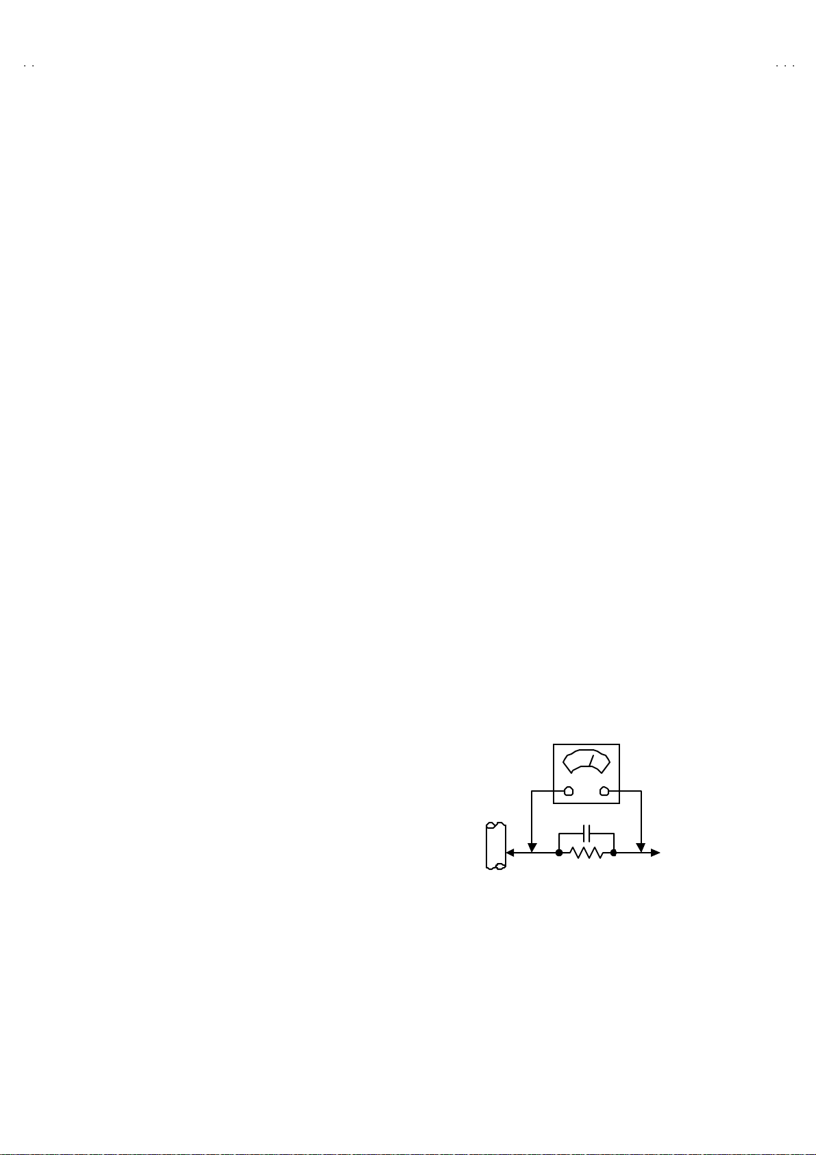
"""" Altern at e Che ck M ethod
Plug th e AC l in e c ord d ir ect ly into the A C ou tlet (d o n ot use a lin e
isol ati o n transformer during t hi s che c k.). Use an AC v o lt me ter
h avi ng 1 000 oh ms pe r volt or m ore sens it i vity in th e fo llow i ng
mann er . C on nec t a 1 50 0Ω 10W res ist or para lle led b y a 0 .15µF
AC-type c apacit or bet ween an expo sed met al pa rt and a kno wn
g ood e ar th gro un d ( wa ter pi pe , etc.). M eas ure th e AC volt ag e
acr oss th e r es ist or with th e AC vo ltm eter . Move th e r esi s tor
con nec ti on to each ex p ose d me tal par t, p art i cularly a ny exposed
metal p ar t hav in g a r etu rn pat h to the ch ass is, an d m easu re th e
AC vol tag e ac ro ss the r es ist or . Now, re vers e th e plu g in th e AC
ou tl et and repe at eac h m ea s ur em en t. An y vol t age measu red
must no t e xceed 0 .7 5V AC (r.m.s.). This c orresponds to 0.5mA
AC (r.m.s.).
Howeve r, in tropica l area, this must n ot exceed 0.3V AC ( r.m. s.) .
This corresponds to 0.2mA AC (r.m.s.).
AC VOLT METER
(HAVING 1000 Ω /V,
OR MOR E SENSIT IVITY)
0.15μF AC-T YPE
PLACE THIS PROBE
1500 Ω 10W
GOOD EARTH GROUND
ON E A C H EX PO SE D
ME T AL PA RT
No.52025
3
Page 4
A
V-20N3
A
A
V-20NMG3
V-20NMG3B
FEATURES
"
New c h assi s d esign enabl es us e of an int eractive on-scr ee n c ont ro l.
"
Wide ran ge volt age ( 1 10V~240V) AC power input.
" With AUDIO / VI DEO INPUT & OUTPUT te rminal.
"
MUT IN G button can r ed uce th e audi o level to z er o i nst ant l y.
" Func t ion al r em ote contr ol t o oper a te T V set (f or chann el se lect, volum e con tr ol , p ower ON /OFF , etc. ) f rom a d ist anc e.
"
I2C bu s con tr ol ut ilizes single chi p ICs for IF, V /C, DE F. VSM PR ES ET, PRESET & SETUP T OUR.
" By m eans of AUTO PR OGRA M, th e TV s tatio ns c an b e s electe d automatica lly a nd th e TV chann el s c an al so b e r ear r an ged a utom atically.
" Built-i n E CO MO DE (ECONOM Y, ECOLOG Y)
In acco rdanc e with the br ig ht nes s in a roo m, th e brig ht ness and / of con tr ast of th e p ic tur e c an b e a djus t ed autom at ically to mak e the
op ti mu m pictu re whi c h is eas y on the e ye.
"
Built – in ON TIMER, RETURN + & CHILD LOCK.
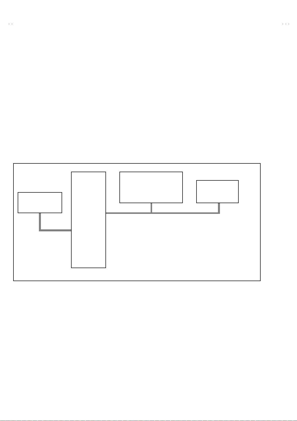
SYSTEM BLOCK DIAGRAM
IC702
MEMORY
SCL2/SDA2
IC701
MICRO
COMPUTER
IC301
VIDEO/CHROMA
DECORDER
SCL1/SDA1
TU001
TUNER
4
No. 52025
Page 5
A
3
A
A
FUNCTIONS
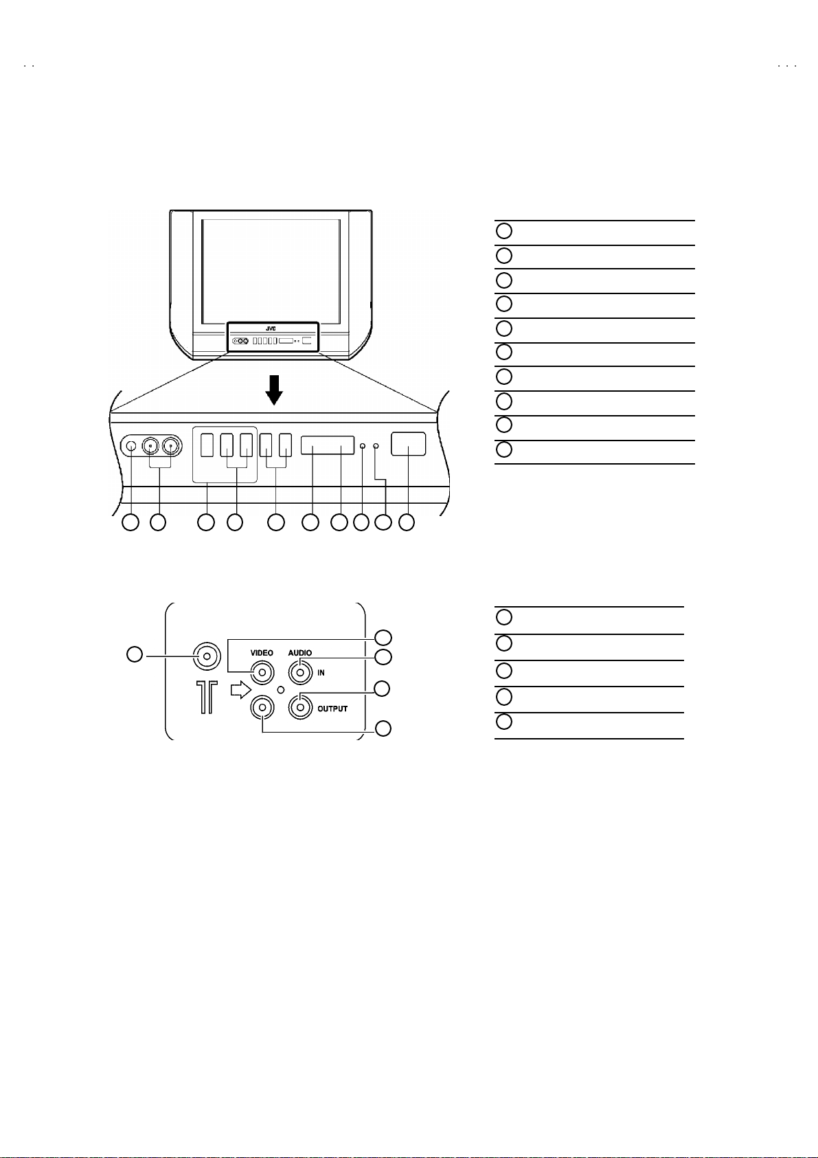
■
FRONT PANEL
MENU buttons
1
CHANNEL -/+ buttons
2
VOLUME -/+ bu tto ns
3
AI ECO sen sor
4
REMO TE CONTR OL s ens or
5
ON TIMER lamp
6
POWER lamp
7
MAIN POWER button
8
A/V IN PUT t ermin al
9
HEAD PHONE jack
10
V-20N
V-20NMG3
V-20NMG3B
10 9 1 2 3 4 5 6
■
REAR TERMINAL
1
7
8
ANT Terminal
1
2
3
4
5
VIDEO INPUT Term inal
2
VIDEO OUTPUT Terminal
3
AUDIO INPUT T ermin al
4
5
AUDIO OUT PUT Terminal
No. 52025
5
Page 6
A
V-20N3
A
A
V-20NMG3
V-20NMG3B
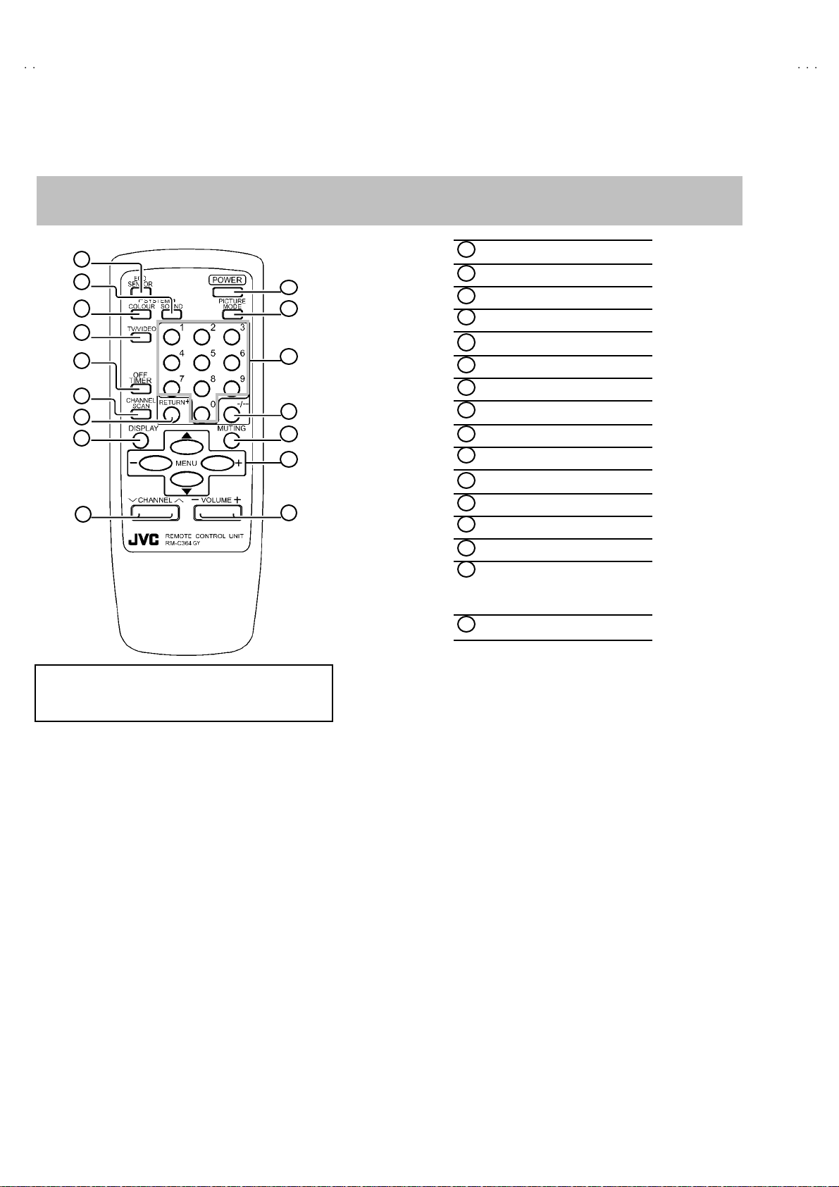
■
REMOTE CO NTRO L UN IT
RM-C364GY : AV-20N3 / AV-20N3/D / AV-20NMG3 / AV-20NMG3
RM-C364 : AV-20NMG3B
ECO S ENSOR ke y
1
2
3
4
5
6
7
8
9
10
11
12
13
14
15
16
1
SOUND SYSTEM key
2
COLOUR SY STEM ke y
3
TV/V IDEO key
4
OFF TIMER key
5
CHA NNEL SC AN k ey
6
RETURN+key
7
DISPLAY key
8
CHANNEL key
9
POWER key
10
PICTURE MODE key
11
Number (CH.) key
12
-/--key
13
MUTING key
14
MENU ke y
15
MENU ▲/▼ key
MENU -/+ key
VOL UME-/+ key
16
/-A
E xce pt f or d if ference i n body co lour , t he R em ote Cont r ol
Unit RM -C 3 64G Y and RM-C 36 4 have exa ctly th e sa me
Func ti ons.
6
No. 52025
Page 7
A
3
A
A
MAIN DIFFERENCE LIST
V-20N
V-20NMG3
V-20NMG3B
Part Name
Model Name
AV-20N3 SCG-1403A-H2
AV-20N3
AV-20NMG3 SCG-1422A-H2
AV-20NMG3B
AV-20NMG3
/D
/-A
Part Name
Model Name
AV-20N3
AV-20N3
AV-20NMG3 A48LDD095X LCT1196- 001A-H LCT1197- 001A-H
AV-20NMG3B
AV-20NMG3
/D
/-A
Main PWB Remote Control Unit Front Cabinet Rating Label
RM-C364GY-1H LC10438-027A-H LC20377-010B-H
SCG-1425A-H2
LC10438-029A-H
RM-C364-1H LC10438-033A-H
RM-C364GY-1H LC10438-029A-H LC20413-002B-H
Picture Tube Inst Book Digest Manual
A48LWX10X LCT1188- 001A-H LCT1189- 001A-H
Item
Model Name
AV-20N3 B/G, I, D/K PAL / SECAM
AV-20N3
AV-20NMG3 B/G, I, D/K,M
AV-20NMG3B
AV-20NMG3
/D
/-A
TV RF System
Co l our S yst em
[RF Mode]
PAL / SECAM
NTSC3.58 / NTSC4.43
Interm ediate
Frequency
[SIF C arri er ]
32.5MHz (5.5MHz)
31.5MHz (6.5MHz)
32.0MHz (6.0MHz)
32.5MHz (5.5MHz)
33.5MHz (4.5MHz)
31.5MHz (6.5MHz)
32.0MHz (6.0MHz)
OSD Language
E / R
E / C / M / I
E / R / A / P
No. 52025
7
Page 8

A
V-20N3
A
A
V-20NMG3
V-20NMG3B
SPECIFIC SERVICE INSTRUCTIONS
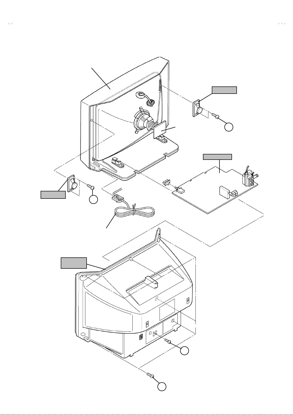
DISASSEMBLY PROCEDURE
REMOVING THE REAR COVER
1. Unp lug t he po wer pl u g.
####
!!!!
.
an d a
2. As sh own in f igur e , remove t he 6 screws marked
screw marked "
3. W i thdr a w t he r ear co ver to wa rd you .
".
""
REMOVING THE MAIN PW BOARD
" After removing the rear cover.
1. Sl ight l y raise t he bo th sid es of t he M AIN PW BOARD by hand .
2. W i thdr a w t he M AIN PW B OARD b ackw ar d.
(If necess ar y, ta k e off the wire c lamp, c onn ect or s etc. )
REMOVING THE SPEAKER
"
After removing the rear cover.
1. As sh own in fi gu r e, remove the 2 screws ma rked
2. Foll ow th e s ame st eps when r em oving the oth er ha nd speak er.
CHECKIN G THE MAIN PW BOARD
1. To ch eck the ba ck side of the PW B oar d.
1) Pu ll out the MA IN PW Bo ard. ( Ref er to RE MO VING TH E MAIN
PW B oar d)
2) Erect th e PW Board vert ic ally so th at you ca n easil y check th e
b ack side of th e PW Boar d.
[CAUTION]
" When e re c ti ng the PW Board, be c ar ef ul s o that th ere w ill b e n o
con tact in g with ot her PW Boar d.
" Before turning on power, make sure that the CRT earth wire and
oth er co nne cto r ar e p rope rly c onn ect ed.
WIRE CLAMPIN G AND CABLE TYING
1. Be sure t o clamp th e wire.
2. N ever rem o ve th e c able tie use d f or tyi ng the wire s to ge the r.
Sh oul d i t be inad verte ntly r em ove d, be su re to tie th e w ires w it h a
new cable tie.
8
No. 52025
Page 9
A
3
A
A
FRONT CABI .
V-20N
V-20NMG3
V-20NMG3B
SP EAKER
SP EAKER
REAR
COVER
C
(×××× 2)
POWER
CORD
CRT SOCKET
PWB
MAIN PWB
C
(××××2)
B
(××××1)
A
(××××6)
No. 52025
9
Page 10
A
V-20N3
A
A
S
U
/C
COLOU
/
MENU
V-20NMG3
V-20NMG3B
REPLACEMENT OF MEMORY ICs
1. MEMORY ICs
Thi s mod el u ses me mo r y I Cs. This memo r y IC da ta are f or pr o per opera tion of th e vide o a nd defl ect io n cir cuits.
When r ep la cing memory ICs , b e su r e to use ICs w r it ten w i th t he ini tial v a lu es of dat a.
2. PROCEDURE FOR REPLACIN G MEMORY ICs
(1) Power off
Switch the p ower of f and di sc o nn ect t he pow e r plu g f rom t he w al l out let.
(2) Replace ICs
Be sure to use memory ICs written with the initial data values.
(3) Power on
Connect th e pow er plu g i nt o the wal l ou tl et and s w itch t he po we r on .
(4) C heck and s et SY STEM CONSTAN T SET
・・・・ It must not adjust without adjustment signals.
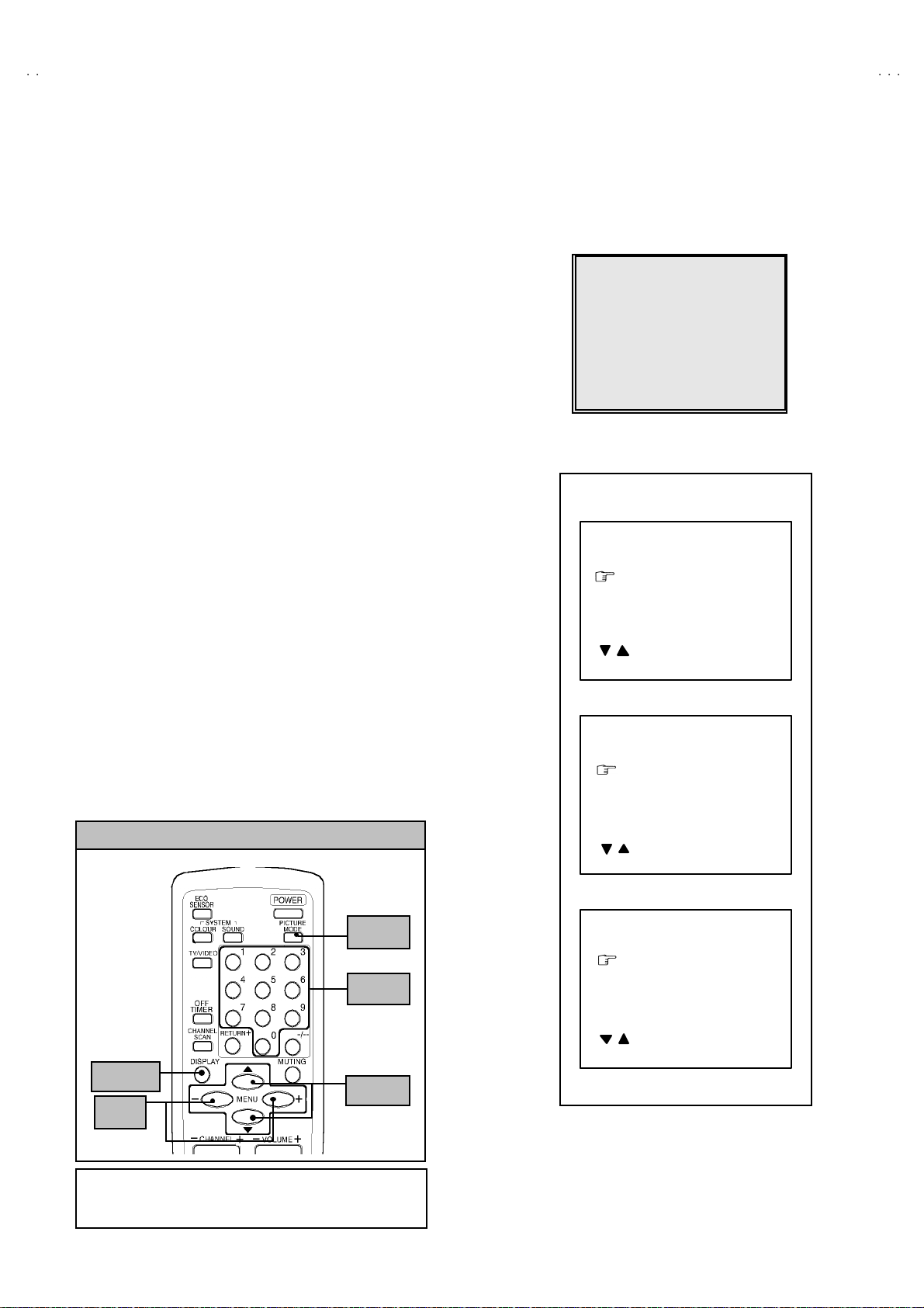
1) Press t he DISPL AY ke y and th e PICTURE MODE key of the RE MOTE
CONTROL UNIT simultaneously.
2) The SERVICE MENU screen of Fig. 1 will be displayed.
3) W hi le th e SE RV IC E M EN U is di splay ed , again press the DI SPLAY ke y and
PICTURE MODE ke y s imulta neo us l y, an d t he S YSTEM C ON ST A NT SE T
screen of Fig. 2 w ill b e di splayed.
4) Check th e sett ing val u es of th e SYS TEM CONSTA NT SET of T abl e 1 If th e
valu e is diff erent, select th e s etting ite m with th e MENU ▼/▲key, and s et
th e co rrect valu e with t he MENU - / + k ey.
5) Press the DI SPLAY ke y twice, and r eturn to th e n or m al scr ee n.
(5) Receive channel of setting
Refe r to th e OPE RATING INST RUCTIONS and set th e r ece i ve c ha nn el s
(chan nels prese t) as descr i be d
(6) User Setting
Check t he us er s ettin g valu e of Tab le 2, a nd if se tti ng value is di f feren t, s et
th e co rrect valu e.
For setting , refer to the OPE RATING INSTRUCTIO NS.
(7) Setting of SERVICE MENU
Ve rif y the s et ting it ems of th e SER VICE MENU, and r eset whe r e n ecess a r y.
For setting , refer to the SERVICE ADJUSTMENTS.
KEY ASSIGNMENT OF REMOTE CONTROL UNIT
ERVICE MEN
1.IF 2.V
3.DEF 4.VSM PRESET
5.PRESET
6.SETUP TOUR OFF
1-6 SELECT DISP : EXIT
******
****** *****
***** **
************
**********
*** ** **
*** ** ** ** ***
*** ** ***** ** **
**.***
****
** ***
** ***** ***
***
******
Fig.1
SY STEM C ON STA NT-
SYSTEM CONSTA NT SE T 1
COL O UR :
BILIN GUAL : N O
TUNE R : MU
ECO SENSOR : YES
LANG U AG E :
: SELECT
/
- / + : OPERATE DISP : EXIT
***
***
SY STEM C ON STA NT- ⅡⅡⅡⅡ
SYSTEM CONSTA NT SE T 2
B/B SO UND :
LOCK : 180
R AUTO:
QSS : MINT
ALC : NO
TEXT R ATE : 2 0
: SELECT
/
- / + : OPERATE DISP : EXIT
***
***
ⅠⅠⅠⅠ
10
PICTURE
MO DE k e y
NUMBERS
key
DISPLAY
-/+
key
key
MENU
▼/▲
key
E xce pt f or d if ference i n body co lour , t he R em ote Cont r ol
Unit RM -C 3 64G Y and RM-C 36 4 have exa ctly th e sa me
No. 52025
SY STEM C ON STA NT- ⅢⅢⅢⅢ
SYSTEM CONSTANT SET 3
AMP T UNER : NO
VNR : YES
TEXT TABLE : CYL
VOLUM PWM : POS
: SELECT
- / + : OPERATE DISP : EXIT
Fig.2
Page 11

A
3
A
A
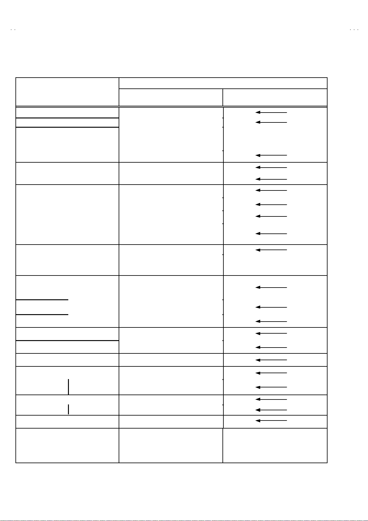
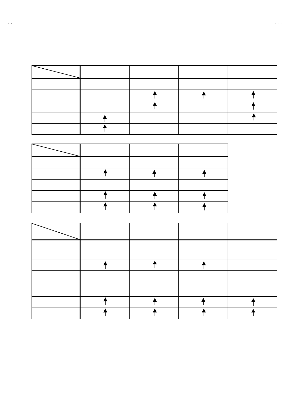
SE TT ING OF SY STEM C ON STANT SET
A
Setting item Setting contents
AV-20N3 AV-20N3
Setting value
AV-20NMG3 AV-20NMG3B AV-20NMG3
/D
V-20N
V-20NMG3
V-20NMG3B
/-A
COLOUR
BILINGUAL
TUNER
AI ECO S ENSOR
LA NG UA G E
B/B SOU ND
LO CK
COLOUR AUTO
QSS
ALC
TEXT RAT E
AMP TUNER
VNR
TEXT TABLE
VOL UM PW M
MUL TI . PA LTRIPLE
YE S NO
MA
MU
YE S
E/R/A /P
ON OFF
YES 10 20 ~ 230
250 240
YE S NO
MI NT MQ SS
YE S NO
10 20 40 80
YE S NO
YE S NO
RA
POS NEG
NO
CYL
E/R
E/C/M/I
TRIPLE MULTI.
NO
MU
YE S
E/R
OFF
18 0
NO
MI NT
NO
20
NO
YE S
CYL
POS
Table 1
E/C/ M/I E/R/A /P
ON
YE S
USER SE T TING V ALUES
Setting item Setting value Setting item Setting value
SUB POWER ON LANGUAGE ENGLISH
CHA NNEL PO SITIO N 1 PO SITIO N CHA NNEL P RE SET Refe r t o OPE RATIN G I NS TRUCTION
VOL UME About 10 AI ECO S EN SOR OFF
TV/V IDEO
ON SCR EEN DI SPLAY
COLOUR SYSTEM PAL ON TIMER PR1 0:00
SOUND SYSTEM B / G BLUE BACK OFF
OFF TIMER OFF OSD.Shows 00 CHILD LOCK OFF
PICTURE MODE (VSM) BRIGHT
TV VNR OFF
POSITION INDICATION AUTO SHUTOFF OFF
Table 2
No. 52025
11
Page 12

A
V-20N3
A
A
)
V-20NMG3
V-20NMG3B
INITIAL SETTING VALUE OF SERVICE MENU
1. Ad just m ent of th e SER VICE MENU is m ade on th e bas is o f the initial set ti ng va lu es ; however, the n ew se tt in g va lu es w hich
set the screen in its optimum condition may differ from the initial setting.
2. Do not change the initial Setting Values of the Setting (Adjustment) items not listed In “ADJUSTMENT”.
2. V/C
Initial set ting v al ue
Setting item
2. DRI VE
3. BR IG HT
Colour sy stem
RED
GREE N1. CUT OFF
BL UE
RED
BL UE
Variabl e
range
-128 ~+127
-128 ~+127
-127~+127
PA L SE CAM NT SC 3.5 8 NT SC 4.4 3
-50
+ 0
+ 0
4. CONT .
5. COLOUR -63~+63 + 0
TV
AV -20N3
6. TINT
7. SECAM BL ADJ. -31~+31
8. SHARP
3. DEFL ECTION
1. VER. POS ITION -04 ~ +03 - 2 - 3
2. HOR. POSITION
3. VER. HEIGHT
4. VE R . L I NE ARIT Y
5. VER. S WCURVE
6. H OR. VC O AD J UST
VI DEO
Do Not Ad j.
Setting item Variabl e range
AV -20N3
AV -2 0NMG 3
AV -2 0NMG 3B
AV -2 0NMG 3
Do Not Ad j.
/D
/-A
TV - 8(Fixed)
VI DEO
-63 ~+63
-63 ~+63
-32~+31
-16 ~ +15
-64 ~ +63
-32 ~ +31
-32 ~ +31
-63 ~ +62
+ 0
+ 0 + 0
+0 - 2
+8 - 2
+ 0
+15(Fixed
Initial set ting v al ue
fv : 50Hz MODE fv : 60Hz MODE
+1 + 4
-40 + 0
+13 - 3
-32 + 0
+ 0 + 0
4. VS M PRESE T
12
VS M pr eset
VSM mode
Setting item
TINT SETTING VA LUE +1 5
COLOUR SE TTIN G VA LU E +15
BR IG HT SET TING VA LUE +1 5
CONT . SE TTING VA LU E +30 +15 + 11
SHARP SE TT IN G VA LU E +1 5 +1 2
BRIGHT STANDARD SOFT
No. 52025
Page 13

A
3
A
A
5. PRESE T
The items in the following table, it i s no requirement for adjustment.
If va lues had changed by t he miss operation, se t the initial settin g v alue s i n the following table.
Colour Sy stem Do Not Ad ju st
V-20N
V-20NMG3
V-20NMG3B
Setting item
1. C TRAP FIX 1 1 1 1
2. SHARP PEAK 0 0 0 0
3. A BL 1 1 1 1
4. GAMMA 0 0 0 0
TV 0 2 2 3
5. Y. DE LAY TIME
VI DEO 0 2 0 2
6. BL ACK EX P STAR T
TV 1 1 0 0
7. C-BPF
VI DEO 1 1 1 1
8. CW / SCP 0 0 0 0
9. VIF DET LEVEL 0 0 0 0
11. IF AGC MIN 0 0 0 0
12 . VIF AGC 0 0 0 0
13. VIF PM OD 0 0 0 0
19 . VN R 15 15 15 15
PA L SE CAM NT SC 3.5 8 NT SC 4.4 3
+3 +3 +3 +3
Initial set ting v al ue ( Fixed value)
20 . R GB LIM 1 1 1 1
21. RGB LIMIT LEVEL 2 2 2 2
23. TEXT H. POSITION -3 -3 -3 -3
24. READ DATA
Sound System D o No t Adj u s t
Setting item B/G I D/ K M
10. SIF DET L EVEL +0 +0 +0 +0
14. SIF BP F BW ADJUST
15. SIF TRAP FO ADJUST +0 +0 +0 +0
16. SIF TRAP FO ADJUST 2 +0 +0 +0 +0
17. SIF -TRAP 0 0 0 0
18. SIF -BPF 1 0 0 0
22 . SIF SW 0 1 1 1
+
0
+
0
+
0
+
0
No. 52025
13
Page 14

A
V-20N3
A
A
V-20NMG3
V-20NMG3B
REPLACEMENT OF IC301 (IF V/C DECODER)
" For the IC301(IF V/C DECODER) of this mode l, a ll data are written in the micro-computer. So, wri te th e data i n the micro-
computer in accordance with the following procedures before starting adjustment.
PROCEDURES
(1) Tur n t he POWE R O F F.
(2) Rep l ace t he IC30 1 w i th a new o ne.
(3) Whi l e pr essi ng ME NU bu tton a nd VO L+ butto n ON the FRO NT C ABINE T s imult ane ous ly, turn th e POW ER O N. W h en th e POW ER i s
turn ed ON, th e d at a is w ritten in the m icro-compute r immed iately.
LOCATIONS OF FRONT PANEL BUTTONS AND LAMPS
MENU buttons
MENU buttons
1
CHANNEL ・ / ・ buttons
CHANNEL -/+butto ns
2
(ME NU ・ / ・ bu tt ons )
(ME NU -/+b uttons)
VOLUME -/+ buttons
VOLUME -/+ buttons
3
(MENU -/+ bu tto ns)
(MENU -/+ bu tto ns)
AI ECO sensor
AI ECO sensor
4
REMOTE CONTROL sensor
REMOTE CONTROL sensor
5
ON TIMER lamp
ON TIMER lamp
6
POWER lamp
POWER lamp
7
MAIN POW ER button
MAIN POW ER button
8
14
No. 52025
Page 15

A
3
A
A
SERVICE ADJUSTMENTS
BEFORE STARTING SERVICE ADJUSTMENT
V-20N
V-20NMG3
V-20NMG3B
1. There ar e 2 w ay of adjus ti ng thi s TV: One i s wi th t h e
REMOTE CONTROL UNI T and the other is the conventional
method using adjustment parts and components.
2. The adjustment with the REMOTE CONTROL UNIT is made
on the basis of t he initia l se tting v alue s. The sett ing values
which adjust the screen to its optimum condition may differ
from the initia l s etting v al ues.
3. M ake s ur e th at connect ion is c orrec t l y made t o AC p ower
source.
4. Turn on t he power of th e se t an d eq uipm en t bef or e us e, an d
start t he adju stm en t proc edure s af ter waitin g at least 30 min utes.
5. Unless ot her w i se s pec ified, pr ep ar e th e mo st sui ta ble r ec epti o n
or inp ut si gn al for adj ust m ent.
6. N ev er t ouch a ny adjus tme n t part s, whi ch ar e not sp e cified
in the li st for thi s ad justme nt VRs , tra nsf or ms, c ond e n ser s,
etc.
7. Pr ep arati o n f or ad justmen t
Unless otherwise specified in the adjustment instructions, preset
the following functions with the REMOTE CONTRO L UNIT.
User mode position
MEASURING INSTRUMENT AND FIXTURES
1. DC voltmeter (or digital voltmeter)
2. Oscilloscope
3. Si gn al g ener at or (P att er n g ener at or) [ PAL / S EC AM / N T S C]
4. Remote control unit
PICTURE MODE (VSM) BRIGHT
VNR OFF
TINT / COLOUR / BRIG HT
CONT. / SHARP
BLUE BA CK OFF
OFF TIMER OFF
AI ECO S ENSOR OFF
AUTO S HUT O FF OFF
CENTER
ADJUSTMENT ITEMS
Adjustment it em Adjustment it em
B1 POW E R SUPPLY
FOCUS adjustment VSM PRESET setting
IF ci rc uit a djust me nt
V/C (Video / Chroma) circuit adjustment
DEFLECTION c ircuit adjustment
PURITY/ CO NV ER GEN C E adj us tm ent
No. 52025
15
Page 16

A
V-20N3
A
A
3
PICTURE
t
V-20NMG3
V-20NMG3B
BASIC OPERATION OF SERVICE MENU
"
The adjustment using SERVICE MENU
The f ol lowing adjus tme nt it ems us e t he SE RV IC E M EN U in th e s er ies of the adj u s tm ent . The ad ju stment s are made on the bas is of the
initial s e tting val u es. The ad ju stm ent valu es whic h ad ju st t he s cr een to the o pti m um co ndit io n c an be diffe rent from the i n iti a l sett in g values.
With th e SER VICE ME NU, various s ett in gs c an be made , a nd the y are broa dl y c l ass ifi e d i n the f ollo win g ite ms of s etti n gs.
1.I F ・・・・・・・ ・・・・・・・・・・・・・ ・・・ Ad justment of th e IF cir cuits.
2.V /C ・・・・・・・・・・・・・・・・・・・・・・ Ad ju stm en t of th e VID EO /CHRO MA cir cuit.
3.DEF ・・・・・・・・・・・・・・・・・・・・ ・ Ad justm ent of the DEFL ECTION circuit.
4.V SM PRES ET ・・・・・・・ ・・・・・ Ad ju s tm en t of th e i ni t ia l sett in g va lue s of VSM c o nd it ion as STA NDA RD, SOFT a nd BRIGH T.
(VSM : Video Status Memory)
5.PRESET
6. SETUP TOUR OFF ・・・・・・・ It s hould be abl e to sel ect mode ( LAN GU AG E a nd AU T O CH PRESE T )..
"
Key operation of the SERVICE MENU
[Enter to SERVICE MENU]
Press the DI SPLAY key and the PICTURE MODE key of the REMOTE CONTROL
UNIT s imult an eou sly. Th en enter the S ERVICE ME N U mod e as sh own in Fig.1 .
[Exit from SERVICE MENU]
When co m plete th e ad j ust me nt wor k , pr ess th e DISPLA Y key to retur n t o th e
SERVICE MENU.
An d th en pr es s the DISPLA Y ke y ag ain, retur n to the n or m al sc r een .
[ Se lec t fr o m SE RV IC E ME NU ]
In SER VI CE M ENU, pr ess t he n umber ( 1 ~6) ke y of th e r emo te c ont ro l un it , to select
an y of th e ad j ustm en t ite ms.
The colours w hi ch se le cte d i te m charact ers a r e ch ang ed .
・・・・・・・ ・・・・・・・・・・
Adjustment of the RF circ uit [Do not adjust].
[Should be OFF].
SE RVICE M EN U
1.IF 2.V/C
.DEF 4.VSM PRESET
5.PRESET
6.SETUP TOUR OFF
1-6 SELECT DISP : EXIT
******
***********
***** **
************
**********
*** ** **
*** ** **** ***
*** ** ***** ** **
**.***
****
** ***
** ***** ***
***
******
Fig.1
KEY ASSIGNMENT OF REMOTE CONTROL UNIT
MO DE k e y
NUMBERS
key
DI SPL A Y k ey
MENU
-/+
key
MENU
▼/▲ key
Exc e pt f or diff er enc e i n bod y colo ur, t he R e mo te Contr o l U ni
RM-C 36 4G Y and RM-C3 64 ha ve exac tl y t he s am e Fu nctions.
16
No. 52025
Page 17

A
3
A
A
[Method of setting]
1. IF
[1. VCO]
① 1 K ey ・・・・・・・ ・・・・・・・・・・・・・ ・・・・・ Select 1.IF.
② 1 K ey ・・・・・・・ ・・・・・・・・・・・・・ ・・・・・ Select 1.VCO
③ The VCO (CW) screen will be displayed a allow mark when the AFC voltage is at a certain level.
④ DISPLA Y K ey・・・・・・・ ・・・・・・・・・・・ As you press this key twice, you will return to the SERVIC E M E NU.
[2. DELA Y P OINT]
① 1 K ey・・・・・・・ ・・・・・・・・・・・・・ ・・・・・ Select 1.IF.
② 2 K ey・・・・・・・ ・・・・・・・・・・・・・ ・・・・・ Se le ct 2.DELAY P OINT.
③ ME NU - /+ K ey ・・・・・・・ ・・・・・・・・・・ Set (adjust) the setting valu es of th e s etting items.
④ DISPLAY K ey・・・・・・・・・・・・・・・・・・ W hen th is is presse d twice, you will r et urn t o the SE RVICE MENU .
2.V /C, 3.D EF and 4 .V SM PRES ET
① 2~4Key ・・・・・・・・・・・・・・・・・・・・ ・・・ Select one from 2. V/C, 3. DE F an d 4. VSM PRESET.
② MENU ▼/▲ Key ・・・・・・・・・・・・・・ Select s etting items.
③ MENU -/+ Key ・・・・・・・ ・・・・・・・・・・ Adju st th e va lues of t he i tem s.
④ DISPLA Y K ey ・・・・・・・・・・・・・・・・・・ W hen this is pr esse d, re turn t o t he SE RVICE MEN U.
V-20N
V-20NMG3
V-20NMG3B
6.SE TU P TOUR
① B y pres sing the 6 key, you can ch ange t he ON or OFF ( should be OFF).
(Should be OFF)
%・
The JVC’s logo will be shown about 15 s econds automatically.
② MENU -/+ Key ・・・・・・・ ・・・・・・・・・・ Select Language.
③ MENU ▼ Key・・・・・・・ ・・・・・・・・・・ Au to Se ar ch.
If it is ON , th en y ou tu rn th e TV po we r off , wh en y ou ar e t urn t he TV p ower o n a gain .
No. 52025
17
Page 18

A
V-20N3
A
A
JUS
6.SETU
ON /
(By p
y)
G
(R)
S
U
O
V-20NMG3
V-20NMG3B
SERVICE MENU FLOW CHART
SE RVICE M EN U
ERVICE MEN
1.IF 2.V/C
3.DEF 4.VSM PRESET
5.PRESET
6.SETUP TOUR OFF
1-6 SELECT DISP : EXIT
******
****** *****
***** **
************
**********
*** ** **
*** ** ** ** ***
*** ** ***** ** **
P TOUR
**.***
****
** ***
** ***** ***
FF
OFF
***
******
ressing 6-ke
SU B ME NU 1. I F
IF
1. VCO
2. DELAY PO INT
1-2 : SELECT DISP : EXIT
SU B ME NU 2. V /C
V/C PAL
1. CUTOFF
50Hz
/ :SELECT
- / + : OPERATE DISP : EXIT
(G)
(B)
* **
* **
* **
VCO (CW)
TOO HIGH
ABOV E REFERENCE
BELOW REF ERENCE
TOO LOW
AFT ADJUST
VCO ADJUST
FINE
DELAY POINT UHF
AGC TAKE- OVER
- / + : OPERATE DI SP : EXIT
***.**
T REFERENCE
MH z
** *(* *)
** *(* *)
** *(* *)** *(* *)
** *(* *)
** *(* *)
** *(* *)** *(* *)
DISP : EXIT
**
SU B ME NU 3. D EF
DEF
1. VER. POSITION
50Hz
/ :SELECT
- / + : OPERATE DISP : EXIT
PAL
***
SUB ME NU 4. V SM PR ES ET
BRI GHT
TINT
COLO UR
HT
BRI
CONT.
SHARP
/ :SELECT
- / + : OPERATE DISP : EXIT
**
**
**
**
**
SUB ME NU 5. P RE SET
18
PRESET
1. C -TRAP FI X
50Hz
/ :SELECT
- / + : OPERATE DISP : EXIT
PAL
B/ G
***
No. 52025
Page 19

A
3
A
A
ADJUSTMENT LOCATIONS
)
V-20N
V-20NMG3
V-20NMG3B
TOP
MAIN PWB
F9 01
CRT SOCKET PWB
TP-47R/G
TP-47G/R
T
IC701
(SOLDER SIDE)
U
TP-47B
TP-E
E1
CRT EARTH WIRE
(BRAIDED ASS'Y)
IC702
MEMORY IC
FRONT
DEG
PW
S
TU001
IC301
T
1
S
1Pin TP-91(B1)
2Pin NC
3Pin X-ray1
4Pin X-ray2
5Pin TP-E(
HV
U
HVT
UPPER:FOCUS
LOWER:SCREEN
No. 52025
19
Page 20

A
V-20N3
A
A
)
adjust
JUS
V-20NMG3
V-20NMG3B
ADJUSTMENTS
B1 POW ER SUPPLY
Item
Check of
B1 Powe r
Measuring
instrume nt
Signal
generator
Supply
DC Vo lt meter
FOCU S ADJUSTMENT
Item
Ad j ust men t
of FOCUS
Measuring
instrume nt
Signal
generator
IF CIRCUIT ADJUS TMENT
Item
Measuring
instrume nt
Test point Ad justment part Description
TP-91 ( B1)
TP-E (####)
1. Input a whole bl ac k s ig na l.
2. C on nec t a DC vo lt me ter t o TP- 9 1( B1) a nd T P- E ( #).
3. M ake sure t hat the vol t age i s DC1 16.5±2.0 V.
Test point Ad justment part Description
FOCUS VR
[In HVT]
1. Input a cross-hatch signal.
2. Whi le watchi n g th e s cr een, adjust the FO CUS V R t o make th e
ver ti cal and ho ri zonta l l ines as f in e a nd sha rp as possi b le.
3. M ake sure th at wh en the scr ee n is d arken ed, the lin es re ma i n in
g ood focu s.
Test point Ad justment part Description
Ad j ust men t
of VCO(CW
Signal
generator
Remote
control unit
VCO (CW)
TOO HIGH
AB OVE REFEREN CE
JU ST REF ER ENCE
BEL OW R EFERE N CE
TOO LOW
AFT AD JUST
VCO ADJUST
FINE
DISP : EXIT
ADJUSTMENT AT THIS POINT IS USELESS
***.**
MHz
** *(* *)
** *(* *)
** *(* *)** *(* *)
** *(* *)
** *(* *)
** *(* *)** *(* *)
ADJUSTMENT POINT
1. VC O
YE LLOW
Do not
TOO HIGH
ABOVE REFERENCE
T REFE RENCE
B ELO W RE F E RE NC E
TOO LOW
●Please use signal generator which is correct proof about the
sen ding fr eque nc y.
1. Inp ut th e PA L f ull col o ur b ar (2 10 .2 5MHz) sig nal.
2. En ter th e SER VICE ME NU.
3. Select 1 .IF f ro m the SERVICE M ENU.
4. Pr es s 1 ke y an d s elect 1. VCO.
5. Select VCO ADJ UST with MENU ▲/▼ key.
6. Pr es s MENU -/+ k ey unt i l th e c o l our of t he c haract ers T OO
HIGH ch an ges b lue to ye llow. Then g r ad uall y press th e MEN U
-/+ key u ntil the TOO LOW ch ang es yellow . At thi s t im e, conf irm
th at t he val u e of VCO ADJUST is n ear + 00 .
7. Select AFT ADJUST with MENU ▲/▼ key.
8. Press MENU -/+ key until the characters JUST REFERENCE
ch ang es bl ue to yellow .
9. Pr es s the DISPLA Y key three times to return to normal screen.
20
No. 52025
Page 21

A
V-20N
3
A
A
(QAU0287-001)
(QAU0185-004)
(QAU0282-001)
V-20NMG3
V-20NMG3B
Item
Ad j ust men t
of DELAY
POI NT
(AGC)
Measuring
instrume nt
Signal
generator
Remote
control unit
DELAY POINT UHF
AGC TA KE-OVER
- / + : OPERATE DISP : EXIT
Test point Adjustment part Description
**
DELAY P OINT
(AGC TAKE-OVER)
1. Inp ut a blac k and wh it e sign al ( colo ur of f).
2. En ter th e SER VICE ME NU.
3. Select 1. IF f rom t he SER VI CE M ENU.
4. Select 2. DELAY POINT by p r essi ng the 2 key on t he remo te
control unit.
5. Se t th e set ting v al ues of t he sett ing i t ems as sh own b ell ow
tabl e.
6. Then adjust the MENU - or + key until video noise disappears.
7. Turn t o o the r cha nnels an d m a ke su re th at th er e ar e n o
irregularities.
Setting It e m Variabl e ra nge Initial set ting v alue
DELAY P OINT
(AGC TAKE OVER)
NT SC 3.5 8
OTHER
0~127
MATSUSHITA
45 45 45
35 45 35
MURATA
ALPS
No. 52025
21
Page 22

A
V-20N3
A
A
(B)
V-20NMG3
V-20NMG3B
VIDEO / CHROM A CIRCU IT ADJUSTMENT
The setting (adjustment) using the REMOTE CONTROL UNIT is made on the basis of the initial setting values.
The setting values which adjust the screen to the optimum condition can be different from the initial setting valu es.
Do not c hang e the initial setting v alue s of the sett ing items n ot liste d in “A DJUSTMENT”.
Item
Ad j ust men t
of WHITE
BALANCE
(Low light)
Measuring
instrume nt
Test point Ad justment part Description
Signal
generator
Remote
control unit
V/C PAL
1. C UTO FF
50Hz
/ :SELECT
- / + : OPERATE DISP : EXIT
(R)
(G)
(B)
* **
* **
* **
KEY ASSIGNMENT OF REMOTE CONTROL UNIT
CU TO FF O F F
(H.LINE OFF)
CU TO FF O N
(H.LINE ON)
R. CUTOFF( )
R. CUTOFF( )
▲
▲
R. DRI VE( )
▼
R. DRI VE( )
▼
123
4
7
56
8
9
RGB
1. CUT OFF (R)
CUT OFF (G)
CUT OFF (B)
SCREEN VR
[IN HVT]
G .C UTOFF ( )
B. C UTO FF( )
B. D RIV E( )
B. C UTO FF( )
B. D RIV E( )
G .C UTOFF ( )
▲
▲
▲
▲
▲
▲
1. Input a bl ac k an d wh it e sign al (col o ur of f).
2. En ter th e SERVICE ME NU.
3. S elect 2. V/C fr om the SERVICE MENU, th en selec t 1. CUT OFF
(R), (G) and (B) .
4. Set each value to initial setting value with 4~ 9 keys of the
remote control unit.
5. Pr ess the 1 key of the remote control unit to sh ow the single
horizontal line on screen.
6. T urn t he SCREEN VR fully counter-cloc kwise, th en slowly tu rn it
cl ockw is e to where on e of a red , blu e or gre en co lour is fai nt ly
vis ible.
7. Use keys 4~9 of th e r e mo te co ntrol un it a nd adjust th e o the r 2
col o ur s which e x cept th e ap pea r ed c olo ur to whe re the si n gl e
h oriz o nt al lin e app ears whit e.
8. T urn th e SCREEN VR to wh er e th e sing l e hor izon ta l li ne gl ow s
fain tly.
9. Pr ess the 2 key to turn of f th e single horizontal li ne.
10.Pr ess the DISP LA Y key twic e to retu rn to the normal scr een.
Adjustment it em
R
G
Variabl e
range
-128 ~+127
-128 ~+127
Initial set ting
value
-50
-501. CUT OFF
B -128~+127 -50
Ad j ust men t
of WHITE
BALANCE
(Hi gh light)
Signal
generator
Remote
control unit
2. DRI VE (R
DRI VE ( B)
)
1. Inp ut a blac k and wh it e sign al ( colo ur of f).
2. En ter th e SER VICE ME NU.
3. Select 2. V/C from the SERVICE MENU .
4. Select 2. DRIVE (R) / (B) with MENU ▼/▲ key, and s et each
val u e to ini tial setti ng valu e with 4 a nd 7 or 6 an d 9 keys of th e
remote control unit.
5. U se th e keys 4 and 7 or 6 and 9 t o p ro duc e a white scr een
V/C PAL
* **
2. D RIV E
50Hz
/ :SELECT
- / + : OPERATE DISP : EXI T
(R)
* **
22
6. Press the DISPL AY key t wice to retu rn to the nomal scree n.
Adjustment it em
Variabl e
range
R -128~+127 +0
2. DRIVE
B
-128 ~+127
No. 52025
Initial set ting
value
+0
Page 23

A
V-20N
3
A
A
V-20NMG3
V-20NMG3B
Item
Ad j ust men t
of
SUB BRI GHT
Ad j ust men t
of
SUB CONT.
Ad j ust men t
of
SUB
COLOUR
ⅠⅠⅠⅠ
Measuring
instrume nt
Remote
control unit
Remote
control unit
Remote
control unit
Test point Adjustment part Description
3. BR IG HT 1. Recei ve an y bro adc ast.
2. En ter th e SER VICE ME NU.
3. Select 2. V/C from S ERVICE MENU.
4. Select 3. BRIGHT with the MENU ▼/ ▲key.
5. Set the initial setting value with the MENU - / + key.
6. If th e brightness is not the bes t with the initial set val ue, make
fine adjustment until you get the best brightness.
4. CONT . 1. Recei ve an y bro adc ast.
2. En ter th e SER VICE ME NU.
3. Select 2. V/C from S ERVICE MENU.
4. Select 4. CONT. with th e MEN U ▼/ ▲ke y.
5. Set the initial setting value with the MENU - / + key.
6. If the co ntr ast is not th e b est w ith t he i ni ti al s et val ue , make fi n e
adjustment until you get the best contrast .
5. COLOUR [Method of adjustm ent without measuring instrument]
PAL COLOUR
1. R eceiv e a PAL broadc ast.
2. En ter th e SER VICE ME NU.
3. Select 2. V/C from t he SERVI CE M EN U.
4. Select 5. COLOUR with the MENU ▼/▲ key.
5. Set the initi al se tti ng va lu e f or P AL C OLOUR with th e MENU
- / + key.
6. If th e colo ur is not th e best with the initial set value, m ake f ine
adjustment until you get the best colour.
SECAM COLOUR
NTSC 3.58 COLOUR
NTSC 4.43 COLOUR
No. 52025
1. R eceiv e a SECAM b roadc ast.
2. M ake fi ne adju stmen t of SE CA M CO LOU R as previ ou sly .
1. R eceiv e a NTS C 3.5 8MHz br oadca st.
2. M ake si milar fine adjustment of NTS C 3. 58 C OLO UR as
previ ously .
When NTSC 3.58 adjustment completed, NTSC 4.43 will be
automatically set at t he resp ective values.
23
Page 24

A
V-20N3
A
A
y
g
(A)
V-20NMG3
V-20NMG3B
Item
Ad j ust men t
of SUB
COLOUR
ⅡⅡⅡⅡ
W
Measuring
instrume nt
Signal
generator
Oscillosc ope
Remote
control unit
Y
C
Test point Ad justment part Description
TP-47G/R
TP-E (####)
[CRT S OCKET
PWB]
5. COLOUR [Method of adjustm ent using measur ing instrument]
PAL COLOUR
1. Inp ut a PA L f ull fi el d colo ur b ar signal (75% w hi te) .
2. En ter th e SER VICE ME NU.
3. Select 2. V/C from S ERVICE MENU.
4. Select 5. COLOUR with the MENU ▼/▲ key.
5. Se t the init ia l se tti ng value of P AL COLO UR with th e MEN U
- / + key.
6. C on nec t the os c illosc ope be tw ee n TP -4 7G and T P- E ( #).
B
R
M
(-)
7. Ad ju s t PA L C OL OU R to bring the value of (A) in the illustration
to the voltage as shown given billow.
(Volt age diff erenc e betwee n ( W) and (G))
Model Voltage(W-G)
AV -20N3
0V
(+)
G
SECAM CO LOUR
1. Input a SECAM full field colour bar signal (75% white).
AV -20N3
AV -2 0NMG 3
AV -2 0NMG 3B
AV -2 0NMG 3
/D
/-A
2. Set the initial setting value of SECAM COLOUR wit h the MENU
- or + key.
3. Ad ju st SE CAM COLO UR to br i ng th e val ue of (A) in the
illu str ati on to th e volt ag e a s sho wn g iven billo w.
(Volta ge di ff er enc e b etw e en (W) an d (G))
Model Voltage(W-G )
AV-20N3
AV-20N3
/D
AV-20NMG 3
AV-20NMG B
AV-20NMG 3
/-A
+14V
+10V
+8V
+10V
NTSC 3.58 COLOUR
1. Inp ut a NTSC 3 .58 full f ie ld colo ur b ar s igna l (75% white) .
2. Set the init ial s etting value of NTSC 3.58 COLOUR wit h the
MENU - / + key.
3. Ad just N TSC 3 .5 8 COL OU R to br in g th e valu e of (A) in the
illu str ati on to th e volt ag e a s sho wn g iven billo w.
(Volta ge di ff er enc e b etw e en (W) an d (G))
Model Voltage(W-G)
AV-20N3
AV-20N3
/D
+11V
AV-20NMG 3
+10V
NTSC 4.43 COLOUR
AV-20NMG 3B
AV-20NMG 3
/-A
When NTSC 3.58 is set, NTSC 4.43 will be automatically set at the
resp ec ti ve val ues .
24
No. 52025
Page 25

A
V-20N
3
A
A
g
V-20NMG3
V-20NMG3B
Item
Ad j ust men t
of TINTⅠⅠⅠⅠ
Ad j ust men t
of TINTⅡⅡⅡⅡ
Measuring
instrume nt
Signal
generator
Remote
control unit
Signal
generator
Oscillosc ope
Remote
control unit
Test point Adjustment part Description
6. TINT [Method of adjustment without measuring instrument]
TP-47G/R
TP-E (####)
[CRT
SOCKET
PWB]
NTSC 3.58 T INT
NTSC 4.43 TINT
6. TINT [Method of adjustment using measur ing instrument]
NTSC 3.58 T INT
1. Input a N TSC 3.58 full f ie ld col our b ar s igna l (75% white) .
2. En ter th e SERVICE ME NU.
3. Select 2. V/C from S ERVICE MENU.
4. Select 6. TINT with t he ME NU ▼/▲ key.
5. Se t th e i ni ti a l se tti ng valu e of N T SC 3. 58 with th e M EN U - / +
key.
6. If you can no t g et th e best ti nt wi th the in it ia l se tting value, make
fine adjustment until you get the best tint.
When NTSC 3.58 is set, NTSC 4.43 will be automatically set at the
resp ec ti ve val ues .
1. Input a N TSC 3.58 full f ie ld col our b ar s igna l (75% white) .
2. En ter th e SERVICE ME NU.
3. Select 2. V/C from S ERVICE MENU.
4. Select 6. TINT with t he ME NU ▼/▲ key.
5. Se t th e i ni ti a l se tti ng valu e of N T SC 3. 58 with th e M EN U - / +
key.
6. Con nect th e osc il losc ope be tw ee n TP -4 7G/R a nd T P- E.
7. Ad ju s t N TSC 3 .58 TIN T t o br i ng th e va lue of (B) in the
illu str ati on to th e volt ag e a s sho wn g iven billo w.
(Volta ge di ff er enc e b etw e en (W) an d (Cy))
W
B
R
M
(-)
AV-20N3
0V
Y
Cy
G
(B)
(+)
NTSC 4.43 TINT
AV-20N3
AV-20NMG 3
AV-20NMG 3B
AV-20NMG 3
When NTSC 3.58 is set, NTSC 4.43 will be automatically set at the
resp ec ti ve val ues .
Model Voltage(W- Cy)
/D
/-A
+9V
+9V
No. 52025
25
Page 26

A
V-20N3
A
A
V-20NMG3
V-20NMG3B
Item
of SECAM
BL AC K
OFF SET
KEY ASSIGNMENT OF REMOTE CONTROL UNIT
COLOUR
ON
COLOUR
OFF
Measuring
instrume nt
Remote
control unit
Signal
generator
12 3
Test point Adjustment part Description
7.SECAM
BL ADJUST
[Method of adjustment using measur ing instrument]Ad j ust men t
1. Inp ut a SE C AM full field c olour b ar si gn al.
2. En ter th e SER VICE ME NU.
3. Select 2. V/C from S ERVICE MENU.
4. Select 7. SECAM BL ADJUST with ▼/▲MENU key.
5. Set the initial setting value with the – or + MENU key.
6. Switch the ①ke y (c ol ou r OF F) an d ②key (c olour O N) o n the
remote contr ol an d ma ke sur e th at th er e is no col o ur on th e
blac k an d w h it e scr ee n.
7. If t he bl a ck and whi te s cre en is n ot bes t with th e ini ti al setti ng
value, make fine adjustment until you g et the best black and
white screen .
8. W hi l e wa tching the s cr ee n, ad ju st th e v alu e to be t he sam e
col o ur b etween O N & OFF b y t en key on t he remote c ontr o l
un it.
9. Press the DISPL AY key t wice to retu rn to the normal scr een.
4
7
56
8
9
26
No. 52025
Page 27

A
3
A
A
DEFLECTION CIRCUIT ADJUSTMENT
"
The re ar e 2 m od es of adju stm ent (s ettin g value) ---- -- ① 50 Hz m od e and ② 6 0Hz m od e ----- de pe ndi n g upo n th e kind of s igna ls
(ver tic al freq uenc y 5 0Hz / 60Hz) .
"
When ad j uste d i n mod e ① , mode ② will be automatically set.
The setting (adjustmen t) usin g the REMOTE CONTROL UNIT is made on the basis of the initial setting values.
The setting values which adjust the screen to the opti mum condition can be different fr om the initial settin g values.
V-20N
V-20NMG3
V-20NMG3B
Item
Ad j ust men t
of V.HEIG HT
&
V. POSIT I ON
Screen
size
92%
Measuring
instrume nt
Test point Adjustment part Description
Signal
generator
Remote
control unit
SU B ME NU 3. D EF
DEF
1. VER. POSITION
50Hz
/ :SELECT
- / + : OPERATE DISP : EXIT
Scre en size
1. VE R. POSITION
3. VE R. HE I G HT
PAL
***
Picture
size
10 0%
1. Input a circle p att ern si gnal.
2. En ter th e SER VICE ME NU.
3. Select 3. DEF. f rom SERVICE MENU.
4. Select 1 . VER. POS ITION with the MENU ▼/▲ key.
5. Set the initial setting value with the MENU - / + key.
6. Adjust V and V’ t o be eq ual with the MENU - / + key as s hown in
Fig.2.
7. Inp ut a cr os s -hatc h s ign al.
8. Select 3. V . HEIG HT with the MENU ▼/▲ key.
9. Set the initial setting value with the MENU - / + key.
10 . As s hown i n F ig.1, adj u st VE R. HE I GH T and m ak e th e verti cal
screen size 92% of the pi ctu r e siz e with t he MEN U - / + keys of
remote control unit.
Ad j ust men t
of HOR .
POSITION
Pic ture size 1 00%
Fig.1
Signal
2.HOR. POSIT ION 11. Input a ci rcle p attern si gnal.
generator
Remote
control unit
HH"
V
V'
Fig.2
No. 52025
12. Sele ct 2. H OR POS ITION with the MENU ▼/▲ key.
13 . Se t th e ini ti a l sett i ng value of 2. HOR. POS ITION with the
MENU - / + key.
14. Adju st 2. HOR. POSITION to make H= H" as shown in Fig. 2
with the MENU - / + ke y.
27
Page 28

A
V-20N3
A
A
S
V-20NMG3
V-20NMG3B
Item
Ad j ust men t
of VER. LI N.
& VER .
SCURVE
Measuring
instrume nt
Signal
generator
Remote
control unit
Fig .3
Test point Ad justment part Description
4. VER. L IN.
5. VER. S CURV E
TOP
CEN TER
BOTTOM
●●●● Whe n the v ertic al linea rity has b ee n dete riorated
remark ably, perform the followi ng steps .
15 . Input a cross -hatch sign al.
16. Sele ct 4. VER. LIN. with the MENU ▼/▲ key.
17. Set the initial setting value of 4. VE R LIN. with the MENU - / +
key.
18. Sele ct 5. VER. SCURVE with the MENU ▼/▲ key.
19. Set the initial setting value of 5. VER. SCURVE wi t h t h e ME NU
- / + key.
20. Adju st 4. VER. LIN. and 5. VER. SCURVE so that the sp aces
of each lin e as sh own i n F i g. 3 o n TOP, CENTER and
BOTTOM become uniform.
Make su r e th at th e a dj us t me nt is pr o per l y do ne on t he scre en of
60 Hz mode .
[NOTE]
"
Adjust to make both 50Hz & 60Hz are the same v. size and
fine straight line.
"
When ad j ust aga in, adju st 5 0H z m ode fi r s t.
"
When adjust in 60Hz mode, only 60Hz mode is adjust.
VSM PRESET SETTING
Item
Setting of
VS M
PRES ET
Measuring
instrume nt
Remote
control unit
TINT
COLO UR
BRI GHT
CONT.
HARP
/ :SELECT
- / + : OPERATE DISP : EXIT
Test point Ad justment part Description
TINT
COLOUR
BR IG HT
CONT .
SHARP
1. En ter th e SER VICE ME NU.
2. Select 4 . VS M PRESE T from the SERVICE MENU.
3. Select BRIG HT with the PICTURE MODE ke y.
4. Ad ju s t the ME NU ▼/▲ and MENU - / + ke y to b ring the set
val u es of TI NT
tabl e.
5. Resp ecti vely s elect the VSM PRES ET mode f or SO FT an d
STANDARD, and make similar adjustment as in 3 a bove.
~~~~
SHARP to the values shown in the below
•••• VSM PRESET
BRI GHT
**
**
**
**
**
VS M
Setti ng It em
TINT +15
COLOUR +15
BRIGHT + 15
CONT +30 +15 +11
SHAR P +15
BRIGHT STANDARD SOFT
←
←
←←
←←
←
+12
28
No. 52025
Page 29

A
3
A
A
PURITY / CONVERGENCE ADJUSTMENT
PURITY ADJUST MENT
1. Demag ne tiz e CRT w it h the dema gneti zer.
V-20N
V-20NMG3
V-20NMG3B
2. L oose n th e re tain er scr ew of the d efl ec tion yok e .
3. Remove th e wed ge s.
4. Inp ut a g r een rast er si gn al from the signal ge ner at or , an d tur n
th e scr e en to g r een r aste r.
5. Move the deflection yoke backward.
6. Br ing t he lo ng lug of th e purity m agn ets on the sho rt lu g a nd
p osit ion t hem hor i zon tal ly. (Fi g. 2)
7. Ad ju st t he ga p be tween t wo l ug s so that the G RE EN R AS TER
will come into the center of the screen. (Fig.3)
8. M ove the d eflect ion y oke for ward, and fix th e pos iti o n of th e
deflection yoke so that the whole screen will bec ome green.
9. Ins ert th e we dg e t o the t op side of the def lect io n yo ke s o th at it
will not move.
CR T
#
WEDGE
DEFLECTION
YOKE
P
46
P / C
MAGNET S
P/ C MA GN ETS
P : PURITY M AGN E T
4 : 4 P OLES ( con vergence m agn ets)
6 : 6 P OLES (con v er gen ce magn ets )
Fig.1
PURITY MAG NETS
10 . Inp ut a cross hat ch sig nal.
11 . Ve rif y tha t th e scr e en is horiz on tal.
12 . Inp ut red and bl ue r ast er sign als , a nd m ak e sure tha t purity i s
prop er ly ad juste d.
Long lug
Short lug
(FRO NT VIEW )
Bring the long lug over the short lug
and position them horizontally.
Fig.2
GREEN RASTER
CEN TER
Fig.3
No. 52025
29
Page 30

A
V-20N3
A
A
V-20NMG3
V-20NMG3B
STAT IC CONVERGENCE ADJUSTMENT
1. Inp ut a cr oss hatc h sig nal.
2. Usin g 4 - po le con verge nce magn ets , ove rla p t he re d and bl u e
lines in th e c en ter of th e scr een (Fi g. 1) and tu rn the m to
mag ent a (r ed/ blue ).
3. Usin g 6- pol e con ver ge nce ma gn ets, ov er lap the
mag ent a( re d/b lue) a nd g r een li nes in t he c en ter of the screen
an d t urn t hem t o whit e.
4. Rep eat 2 and 3 ab ove, an d ma ke b est c onve r ge nce.
DYNAMIC C ONVERGENCE ADJUSTMENT
1. Move th e d ef lec ti on yok e up an d d ow n and ov er lap th e lin es in
the periphery. (Fig . 2 )
2. M ove the def l ecti on yoke left to ri gh t and over lap t he l in es in the
p erip hery. (Fig. 3)
3. Rep eat 1 and 2 ab ove, an d ma ke b est c onve r ge nce.
(FRO NT VIEW )
(FRO NT VIEW )
BLUE
GREEN
RED
Fig.1
GREEN
BLUERED
RED
GREEN
BLUE
●
After ad justm ent, f ix the wedge at the original p osition.
Fas t en the retainer screw of th e def lecti on yoke .
Fi x the 6 magn ets with g lue.
(FRO NT VIEW )
GREEN
RED
BLUE
GREEN REDBLUE
Fig.2
Fig.3
BLUE
GREEN
RED
RED
GREEN
BLUE
BLUE
GREEN
RED
30
No.52025
Page 31

A
3
A
A
REPLACEMENT OF CHIP COMPONENT
!
CAUT IONS
1. Avoid heating for more than 3 seconds.
2. D o n ot rub t he el ec t ro des an d the resist p arts of the patt ern.
3. W hen rem ovi ng a c hip par t, mel t th e s older adequ atel y.
4. D o n ot reuse a chip p ar t after removi ng it .
! SOLDERING IRON
1. U se a hig h i ns ulatio n s ol der ing iron with a t hin po in ted end of it.
2. A 3 0w s older ing i r on is r ec ommended for easil y r em ovi ng par ts.
! REPLACEMENT STEPS
1. How to remove Chip parts
$$$$ Resi st o rs, capacitors , et c
(1) As s h own in t he f ig ur e, push th e pa rt with tw ee zer s and
alte rn at ely m elt th e sol de r at each en d.
(2) Sh if t w i th tweez e rs and r emo ve th e ch i p p ar t.
$$$$ Trans ist o rs, dio d es , va ria bl e r esistor s, etc
(1) Ap pl y e xt ra s o ld er to each le ad .
SOLDE R SOLD E R
V-20N
V-20NMG3
V-20NMG3B
2. How to install Chip parts
$$$$
Resi st ors, ca pacit o rs , etc
(1) Apply sold er to the patt ern as ind icated in the fi g ure.
(2) Gr asp t he c h i p p art with tweezer s and pl ac e it on th e s ol d er.
The n hea t and me lt th e so lder a t b oth ends of t he chip part.
$$$$ Tran s ist ors, diodes , varia bl e res ist or s, et c
(1) Apply sold er to the patt ern as ind icated in the fi g ure.
(2) Grasp the ch ip p art wit h t we ez e rs and p lace it on th e so l der .
(3) First s older lead A as indicated i n t he figu re.
A
(2) As s h own in t he f ig ur e, push th e pa rt with tw ee zer s and
alte rn at ely m elt th e sold er a t each le ad. S hi ft an d r em ove t he
chip part.
(4) The n solder le ads B and C.
Note : A fte r re moving t he part , remove r emaining solder fr o m the
pattern.
C
A
C
No.52025
B
B
31
Page 32

A
V-20N3
A
A
V-20NMG3
V-20NMG3B
32
No.52025
 Loading...