

Page 1
SERVICE MANUAL
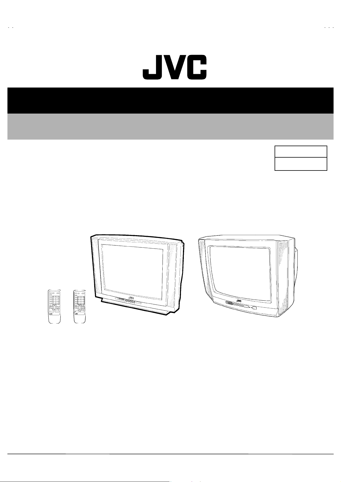
COLOR TELEVISION
AV-21D13
AV-21D33
AV-20N13
AV-20N33
BASIC CHASSIS
RM-C372GY
[AV-21D13/PH]
[AV-20N13/PH]
RM-C373GY
[AV-21D33/PH]
[AV-20N33/PH]
AV-21D13
AV-21D33
AV-20N13
AV-20N33
[AV-21D13/PH]
[AV-21D33/PH]
/PH
/PH
/PH
/PH
GA2
[AV-20N13/PH]
[AV-20N33/PH]
CONTENTS
SPECIFICATIONS ・・・・・・・・・・・・・・・・・・・・・・・・・・・・・・・・
!
SAFETY PRECAUTIONS ・・・・・・・・・・・・・・・・・・・・・・・・・・・・・・・・
!
FEATURES・・・・・・・・・・・・・・・・・・・・・・・・・・・・・・・・
!
MAIN DIFFERENCE LIST ・・・・・・・・・・・・・・・・・・・・・・・・・・・・・・・・
!
FUNCTIONS ・・・・・・・・・・・・・・・・・・・・・・・・・・・・・・・・
!
SPECIFIC SERVICE INSTRUCTIONS ・・・・・・・・・・・・・・・・・・・・・・・・・・・・・・・・
!
SERVICE ADJUSTMENTS ・・・・・・・・・・・・・・・・・・・・・・・・・・・・・・・・
!
PARTS LIST ・・・・・・・・・・・・・・・・・・・・・・・・・・・・・・・・
!
★ OPERATING INSTRUCTIONS
★ STANDARD CIRCUIT DIAGRAM ・・・・・・・・・・・・・・・・・・・・・・・・・・・・・・・・
1
・・・・・・・・・・・・・・・・・・・・・・・・・・・・・・・・・・・・・・・・・・・・・・・・・・・・・・・・・・・・・・・・
・・・・・・・・・・・・・・・・・・・・・・・・・・・・・・・・・・・・・・・・・・・・・・・・・・・・・・・・・・・・・・・・
・・・・・・・・・・・・・・・・・・・・・・・・・・・・・・・・・・・・・・・・・・・・・・・・・・・・・・・・・・・・・
・・・・・・・・・・・・・・・・・・・・・・・・・・・・・・・・・・・・・・・・・・・・・・・・・・・・・・・・・・・・・・・・
・・・・・・・・・・・・・・・・・・・・・・・・・・・・・・・・・・・・・・・・・・・・・・・・・・・・・・・
・・・・・・・・・・・・・・・・・・・・・・・・・・・・・・・・・・・・・・・・・・・・・・・・・・・・・・・・・・・・・・・・
・・・・・・・・・・・・・・・・・・・・・・・・・・・・・・・・・・・
・・・・・・・・・・・・・・・・・・・・・・・・・・・・・・・・・・・・・・・・・・・・・・・・・・・・・・・・・・・・・・・・
・・・・・・・・・・・・・・・・・・・・・・・・・・・・・・・・・・・・・・・・・・・・・・・・・・・・・・・
・・・・・・・・・・・・・・・・・・・・・・・・・・・・・・・・・・・・・・・・・・・・・・・・・・・・・・・・・・・・・・・・
・・・・・・・・・・・・・・・・・・・・・・・・・・・・・・・・・・・・・・・・・・・・・・・・・・・・・・・・・・・・・・・・
・・・・・・・・・・・・・・・・・・・・・・・・・・・・・・・・・・・・・・・・・・・・・・・・・・・・・・・・・・・・・・・・
・・・・・・・・・・・・・・・・・・・・・・・・・・・・・・・・・・・・・・・・・・・・・
・・・・・・・・・・・・・・・・・・・・・・・・・・・・・・・・・・・・・・・・・・・・・・・・・・・・・・・・・・・・・・・・
・・・・・・・・・・・・・・・・・・・・・・・・・・・・・・・・・・・・・・・・・・・・・・・・・・・・・
・・・・・・・・・・・・・・・・・・・・・・・・・・・・・・・・・・・・・・・・・・・・・・・・・・・・・・・・・・・・・・・・
・・・・・・・・・・・・・・・・・・・・・・・・・・・・・・・・・・・・・・・・・・・・・・・・・・・・・・・・・・・・・・・・
・・・・・・・・・・・・・・・・・・・・・・・・・・・・・・・・・・・・・・・・・・・・・・・・・・・・・・・・・・・・・・・・
・・・・・・・・・・・・・・・・・・・・・・・・・・・・・・・・・・・・・・・・・・・・・・・・
・・・・・・・・・・・・・・・・・・・・・・・・・・・・・・・・・・・・・・・・・・・・・・・・・・・・・・・・・・・・・・・・
COPYRIGHT © 2002 VICTOR COMPANY OF JAPAN, LTD.
・・・・・・・・・・・・・・・・・・・・・・・・・・・・・ 2
・・・・・・・・・・・・・・・・・・・・・・・・・・・・・・・・・・・・・・・・・・・・・・・・・・・・・・・・・・
・・・・・・・・・・・・・・・・・・・・・・・ 3
・・・・・・・・・・・・・・・・・・・・・・・・・・・・・・・・・・・・・・・・・・・・・・
・・・・・・・・・・・・・・・・・・・・・・・ 4
・・・・・・・・・・・・・・・・・・・・・・・・・・・・・・・・・・・・・・・・・・・・・・
・・・・・・・・・・・・・・・・・・・・・・・・・・・・・・・・・・
・・・・・・・・・・・・・・・・・・・・・・・・・・・・・・・・・・・・・・・・・・・・・・・・・・・・・・・・・・・・・・・・
・・・・・・・・・・・・・・・・・・・・・ 17
・・・・・・・・・・・・・・・・・・・・・・・・・・・・・・・・・・・・・・・・・・
・・・・・・・・・・・・・・・・・・・・・・・・・・・・・・・・・・・・ 35
・・・・・・・・・・・・・・・・・・・・・・・・・・・・・・・・・・・・・・・・・・・・・・・・・・・・・・・・・・・・・・・・
・・・ 4
・・・・・・
・・ 5
・・・・
・・・・・・・・・・・・・ 8
・・・・・・・・・・・・・・・・・・・・・・・・・・
・・・・・・・・・・・・・・・・ 2-1
・・・・・・・・・・・・・・・・・・・・・・・・・・・・・・・・
No.52022
Jul. 2002
Jul. 2002
Page 2
A
V-21D13
A
A
A
V-21D33
V-20N13
V-20N33
SPECIFICATIONS
Items
Dimensions (W××××H××××D) 598mm×468mm×478mm 619mm×458mm×488mm
Mass 21.0kg 19.0kg
TV RF System CCIR (M)&(N)
Color / Sound System NTSC / PAL-M / PAL-N
TV Receiving Channels
and Frequency
CATV Receiving Channels
and Frequency
TV/CATV Total Channel 181 Channels
Intermediate Frequency Video IF Carrier
VL Band
VH Band
UHF Band
Low Band
High Band
Mid Band
Super Band
Hyper Band
Ultra Band
Sub Mid Band
Sound IF Carrier
AV-21D13
BTSC (Multi Channel Sound) [AV-21D33
(02~06) 54MHz~88MHz
(07~13) 174MHz~216MHz
(14~69) 470MHz~806MHz
(02~06)
(07~13)
(14~22)
(23~36)
(37~64)
(65~94, 100~125)
(01, 96~99)
45.75MHz
41.25MHz (4.5MHz)
/PH / AV-21D33/PH AV-20N13/PH / AV-20N33/PH
(54MHz~804MHz)
Contents
NTSC / PAL-M / PAL-N
BTSC (Multi Channel Sound) [AV-20N33
/PH]
/PH]
Color Sub Carrier NTSC : 3.579545MHz
PAL-M : 3.57561149MHz
PAL-N : 3.58205625MHz
Antenna terminal
Rated VoltagePower Input
Oper ating Voltage
Power Consumption 66W 60W
Picture Tube Vis ible size 51cm measured diagonally Vis ible size 48cm measured diagonally
High Voltage
Speaker
Audio Power Output
Input Video input
Audio input
Output
Headphone Jack Ster eo mini Jack (φ3.5mm)
Video output
Audio output
75Ω(VHF/UHF) Terminal,
F-Type Connector
110V~240V AC, 50Hz/60Hz
90V~260V AC, 50Hz/60Hz
26.5kV±1.0kV (at zero beam current)
5cm×12cm Oval type×2
2W (monaural) [AV-21D13
1.5W+1.5W (stereo) [AV-21D33
1V(p-p) 75Ω (RCA pin jack)
500mVrms (-4dBs) / High impedance
(RCA pin jack)
1V(p-p) 75Ω (RCA pin jack)
500mVrms (-4dBs) / Low impedance
(RCA pin jack)
/PH
]
/PH
]
/PH
2W (monaural) [AV-20N13
1.5W+1.5W (stereo) [AV-20N33
]
/PH
]
Remote Control Unit RM-C372GY [AV-21D13
RM-C373GY [AV-21D33
(AA/R6/UM-3 battery×2)
/PH
/PH
]
]
RM-C372GY [AV-20N13
RM-C373GY [AV-20N33
(AA/R6/UM-3 battery×2)
/PH
/PH
]
]
Design & specifications are subject to change without notice.
2
No.52022
Page 3
A
A
A
A
SAFETY PRECAUTIONS
V-21D13
V-21D33
V-20N13
V-20N33
1. The design of this product contains special hardware, many
circuits and components specially for safety purposes. For
continued protection, no changes should be made to the original
design unless authorized in writing by the manufacturer.
Replacement parts must be identic al to those used in the original
circuits. Service should be performed by qualified personnel
only.
2. Alterations of the design or circuitry of the products should not be
made. Any design alterations or additions will void the
manufacturer's warranty and will further relieve the manufacturer
of responsibility for personal injury or property damage resulting
theref rom.
3. Many electric al and mechanical parts in the products have
special safety-related characteristics. These characteristics are
often not evident from visual inspection nor can the protection
afforded by them necessarily be obtained by using replacement
components rated for higher voltage, wattage, etc. Replacement
parts which have these special safety characteristics are
identified in the parts list of Service manual. Electrical
components having such features are identified by shading
on the schematics and by (!!!!) on the parts list in Service
manual. The use of a subst itute replacement which does not
have the s ame safety characteristics as the recommended
replacement part shown in the parts list of Service manual may
cause shock, fire, or other hazards.
4. Don't short between the LIVE side ground and ISOLATED
(NEUTRAL) side ground or EARTH side ground when
repairing.
Some model's power circuit is partly different in the GND. The
differenc e of the GND is shown by the LIVE : (") side GND, the
ISOLATED(NEUTRAL) : (#) side GND and EARTH : ($) side
GND. Don't short between the LIVE side GND and
ISOLATED(NEUTRAL) side GND or EARTH side GND and
never meas ure with a measuring apparatus (oscilloscope etc.)
the LIVE side GND and ISOLATED(NEUTRAL) side GND or
EARTH side GND at the same time.
If above note will not be kept, a fuse or any parts will be broken.
5. If any repair has been made to the chassis, it is recommended
that the B1 setting should be checked or adjusted (See
ADJUSTMENT OF B1 POWER SUPPLY).
6. The high voltage applied to the picture tube must conform with
that specified in Service manual. Excessive high voltage can
cause an incr ease in X-Ray emission, arcing and possible
component damage, therefore operation under excessive high
voltage conditions should be kept to a minimum, or should be
prevented. If severe arcing occurs, remove the AC power
immediately and det ermine the caus e by visual inspection
(incorrect installation, cr acked or melted high voltage harness,
poor soldering, etc.). To maintain the proper minimum level of
soft X-Ray emission, components in the high voltage circuitry
including the picture tube must be the exact replacements or
alternatives approved by the manuf actur er of the complete
product.
7. Do not check high voltage by drawing an arc. Use a high voltage
meter or a high voltage probe with a VTVM. Discharge the
picture tube before attempting meter connection, by connecting
a clip lead to the ground frame and connecting the other end of
the lead through a 10kΩ 2W resistor to the anode button.
8. When service is requir ed, obser ve the original lead dress. Extra
precaution should be given to assure correct lead dress in the
high voltage circuit area. W here a short circuit has occurred,
those components that indicat e evidenc e of overheating should
be replaced. Always us e the manufacturer's replacement
components.
9. Isolation Check
(Safety for Electrical Shock Hazard)
After re-assembling the product, always perf orm an isolation
check on the exposed metal parts of the cabinet (antenna
terminals, video/audio input and output terminals, Control knobs,
metal c abinet, screwheads, earphone jack, c ontrol shafts, etc.)
to be sure the product is safe to operat e without danger of
electr ical shoc k.
(1) Dielectr ic Strength Test
The isolation between the AC primary circuit and all metal parts
exposed to the user, particularly any expos ed metal part having a
return path to the chass is should withstand a voltage of 3000V
AC (r.m.s.) for a period of one second.
(. . . . Withstand a voltage of 1100V AC (r.m.s.) to an applianc e
rated up to 120V, and 3000V AC (r.m.s.) to an appliance rated
200V or more, for a period of one second.)
This method of test requires a test equipment not generally found
in the s ervice trade.
(2) Leakage Current Check
Plug the AC line cord directly into the AC outlet (do not use a line
isolation transformer dur ing this check.). Using a "Leakage
Current T ester", measure the leakage current from each exposed
metal part of the cabinet, particularly any exposed metal part
having a return path to the chassis, to a known good earth
ground (water pipe, etc.). Any leakage c urrent must not exceed
0.5mA AC (r.m.s.).
However, in tr opical area, this must not exceed 0.2mA AC
(r.m.s.).
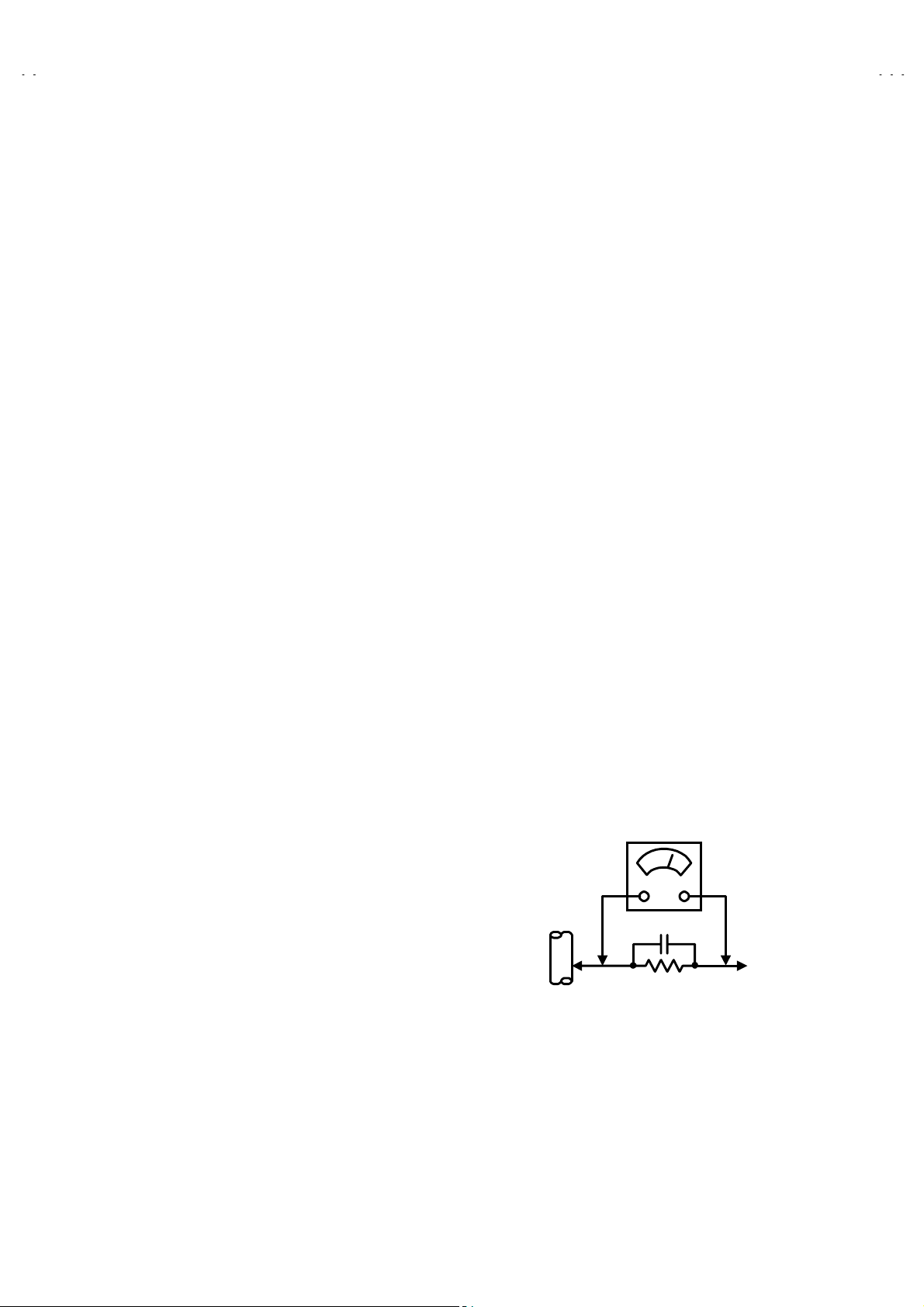
"""" Alternate Check Method
Plug the AC line cord directly into the AC outlet (do not use a line
isolation transformer during this check.). Use an AC volt meter
having 1000 ohms per volt or more sensitivity in the following
manner. Connect a 1500Ω 10W resistor paralleled by a 0.15µF
AC-type capacitor between an expos ed metal part and a known
good earth ground (water pipe, etc.). Measure the AC voltage
across the resistor with the AC voltmeter. Move the resistor
connection to each exposed metal part, particularly any exposed
metal part having a return path to the chassis, and measure the
AC voltage across the resist or. Now, reverse the plug in the AC
outlet and repeat each measurement. Any voltage meas ured
must not exceed 0.75V AC (r.m.s.). This corresponds to 0.5mA
AC (r.m.s.).
However, in tr opical area, this must not exc eed 0.3V AC (r.m.s.).
This corresponds to 0.2mA AC (r.m.s.).
AC VOLTMETER
(HAVING 1000 Ω/V,
OR MORE SENSITIVITY)
0.15μF AC-TYPE
PLACE THIS PROBE
1500 Ω 10W
GOOD EARTH GROUND
ON EACH EXPOSED
METAL PART
No.52022
3
Page 4
A
V-21D13
A
A
A
V-21D33
V-20N13
V-20N33
FEATURES
" New chas sis design enables use of a main board with simplified
circuitry.
" Provided with miniatur e tuner (TV/CATV).
" PLL synthesizer system TV/CATV totaling 181 channels.
" Multifunctional remote control permits picture adjustment.
" With NTSC/PAL-M&PAL-N color/sound systems.
" Adoption of the VIDEO STATUS func tion.
" With 75ΩV/U in common (F-Type) ANT Terminal.
" Wide range rated voltage (110V~240V) AC power input.
" Clos ed-caption broadcasts can be viewed.
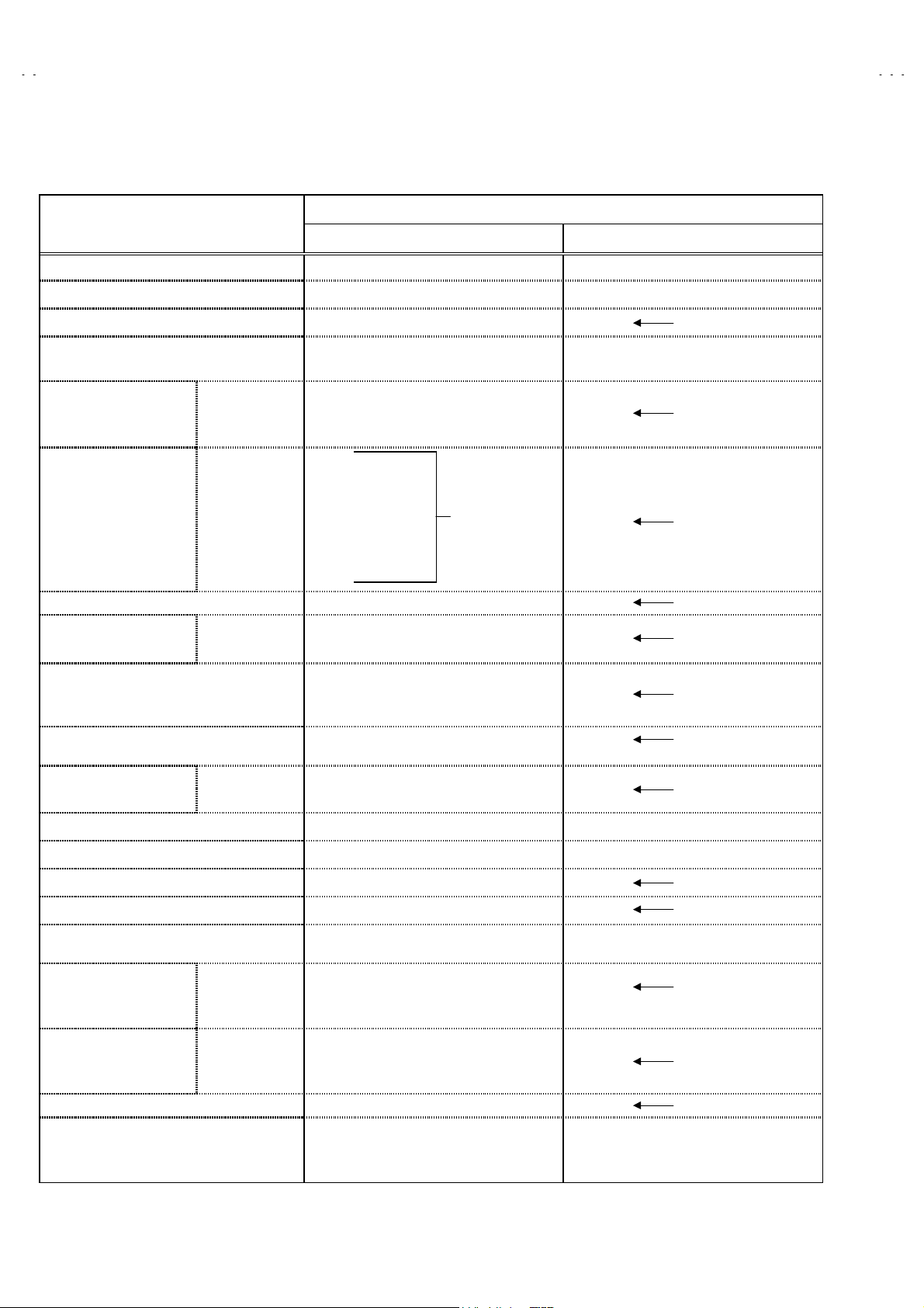
MAIN DIFFERENCE LIST
Model Name
!
Part Name(Item)
MAIN PW B SGA-1062A SGA-1061A SGA-1064A SGA-1063A
REMOTE CONTROL UNIT RM-C372GY-1H RM-C373GY-1H RM-C372GY-1H RM-C373GY-1H
!
FRONT CABINET LC11129-019A-H LC11129-020A-H LC10438-030A-H LC10438-031A-H
!
REAR COVER GG10130-007A-H LC10448-003A-HK
!
PICTURE TUBE A51LEC065X A48KXR064X
TERMINAL SHEET GG30058-002A-H GG30058-001A-H GG30058-002A-H GG30058-001A-H
AV-21D13
/PH
AV-20D33
/PH
AV-20N13
/PH
AV-20N33
/PH
SPEAKER CEBSS12D-07KJ2 CEBSS12D-04KJ2 CEBSS12D-07KJ2 CEBSS12D-04KJ2
PACKING CASE GG10056-076A-H GG10056-078A-H GG10056-074A-H GG10056-075A-H
NTSC / PAL-M / PAL-N
Color / Sound System NTSC / PAL-M / PAL-N
Power Consumption 66W
Speaker
Audio Power Output 2W (monaural) 1.5W+1.5W (stereo) 2W (monaural) 1.5W+1.5W (stereo)
5× 12cm Oval type×2
(monaural)
BTSC(Multi Channel
Sound)
5× 12cm Oval type×2
(stereo)
NTSC / PAL-M / PAL-N
60W
5× 12cm Oval type×2
(monaural)
NTSC / PAL-M / PAL-N
BTSC(Multi Channel
Sound)
5× 12cm Oval type×2
(stereo)
4
No.52022
Page 5
A
A
A
A
FUNCTIONS
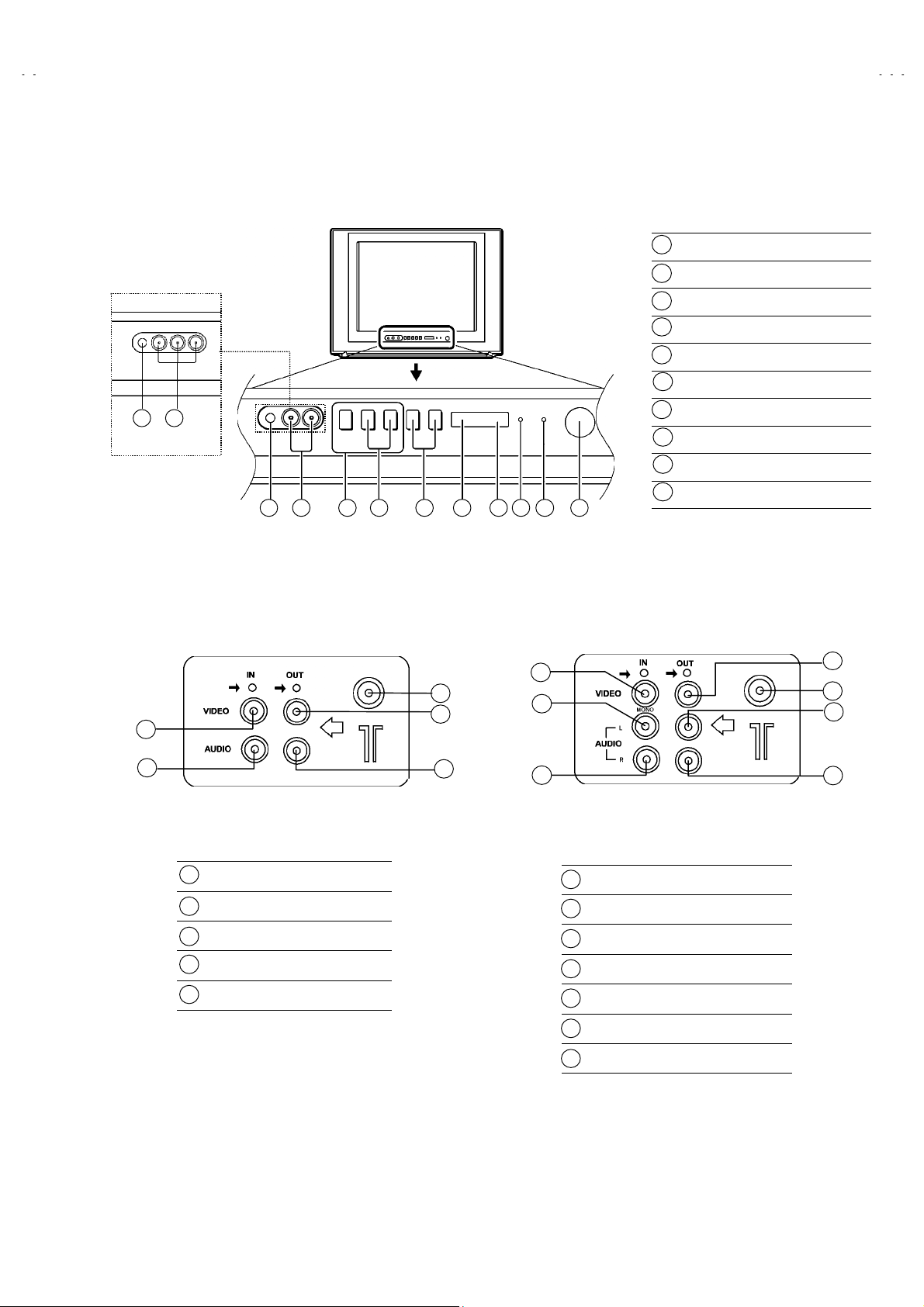
■ FRONT PANEL
V-21D13
V-21D33
V-20N13
V-20N33
910
[AV-21D33/PH]
■ REAR TERMINAL
2
[AV-21D13/PH]
10 9 1 2 3 4 5 6 7 8
2
1
4
3
1
MENU butt ons
CHANNEL -/+ buttons
2
VOLUME -/+ buttons
3
AI ECO sensor
4
REMOTE CONTROL sensor
5
ON TIMER lamp
6
POWER lamp
7
MAIN POWER button
8
A/V INPUT terminal
9
HEADPHONE jack
10
5
1
6
3
[AV-21D13/PH]
1
ANT Terminal
2
VIDEO INPUT Terminal
3
AUDIO INPUT Terminal
4
VIDEO OUTPUT Terminal
5
AUDIO OUTPUT Terminal
5
4
[AV-21D33/PH]
ANT Terminal
1
VIDEO INPUT Terminal
2
AUDIO L/MONO INPUT Terminal
3
AUDIO R IN PUT Terminal
4
VIDEO OUTPUT Terminal
5
AUDIO L OUTPUT Terminal
6
AUDIO R OUTPUT Terminal
7
7
No. 52022
5
Page 6
A
V-21D13
A
A
A
V-21D33
V-20N13
V-20N33
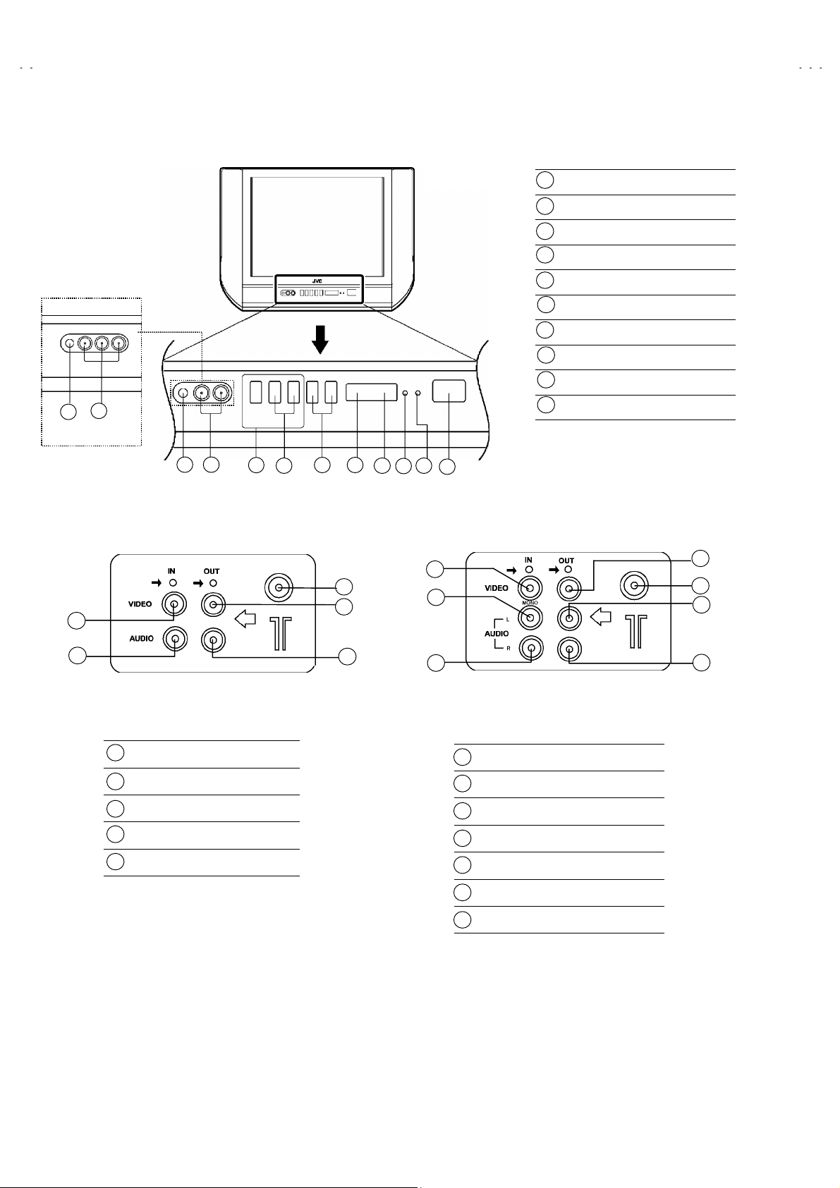
■ FRONT PANEL
9
10
[AV-20N33/PH]
10 9
■ REAR TERMINAL
2
[AV-20N13/PH]
1
3 4
2
5
7
6
1
4
8
2
3
1
MENU butt ons
CHANNEL -/+ buttons
2
VOLUME -/+ buttons
3
4
AI ECO sensor
5
REMOTE CONTROL sensor
6
ON TIMER lamp
7
POWER lamp
8
MAIN POWER button
9
A/V INPUT terminal
10
HEADPHONE jack
5
1
6
3
[AV-20N13/PH]
1
ANT Terminal
VIDEO INPUT Terminal
2
AUDIO INPUT Terminal
3
4
VIDEO OUTPUT Terminal
AUDIO OUTPUT Terminal
5
5
4
[AV-20N33/PH]
1
ANT Terminal
VIDEO INPUT Terminal
2
AUDIO L/MONO INPUT Terminal
3
AUDIO R IN PUT Terminal
4
VIDEO OUTPUT Terminal
5
AUDIO L OUTPUT Terminal
6
AUDIO R OUTPUT Terminal
7
7
6
No. 52022
Page 7

A
V-21D13
A
A
A
V-21D33
V-20N13
V-20N33
■ REMOTE CONTROL UNIT
1
2
3
4
5
6
7
8
9
10
This illustration is written about RM-C373GY(AV-21D33/PH
& AV-20N33/PH),There are no key of HYPER SURROUND in
the RM-C372GY(AV-21D13/PH & AV-20N 13/PH).
11
12
13
14
15
16
17
TV/VIDEO key
1
DISPLAY key
2
PICTURE BOOSTER key
3
CLOSED CAPTION key
4
SLEEP TIMER key
5
VIDEO STATUS key
6
COLOUR SYSTEM key
7
100+key
8
EXIT key
9
CHANNEL-/+ key
10
POWER key
11
Number (CH.) keys
12
RETURN+key
13
HYPER SURROUND key
14
[AV-21D33
MENU key
15
MENU ▲/▼ key
MENU -/+ key
MUTING key
16
17
VOLUME-/+ key
/PH &
AV-20N33
/PH
Only]
No. 52022
7
Page 8

A
V-21D13
A
A
A
V-21D33
V-20N13
V-20N33
SPECIFIC SERVICE INSTRUCTIONS
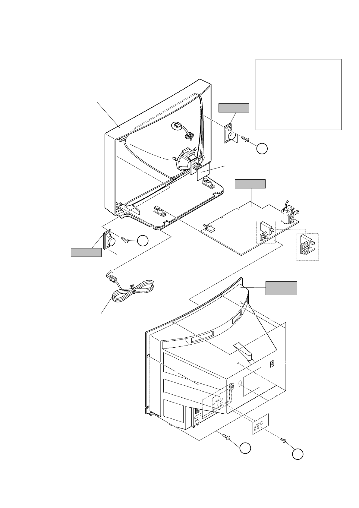
DISASSEMBLY PROCEDURE
REMOVING THE REAR COVER
1. Unplug the power plug.
screws marked
2. As shown in figure, remove the
2 screws marked
3. Withdr aw the rear cover toward you.
""""
.
7
REMOVING THE PW BOARD
" After removing the rear cover.
1. Slightly raise the both sides of the PW BOARD by hand.
2. Withdr aw the PW BOARD backward.
(If necessary, take off the wire clamp, connectors etc.)
REMOVING THE SPEAKER
" After removing the rear cover.
screws marked
1. As shown in figure, remove the
2. Follow the same steps when r emoving the other hand speak er.
2
####
!!!!
.
and the
CHECKING THE PW BOARD
1. To check the back side of the PW Board.
1) Pull out the PW Board. (Refer to REMOVING THE MAIN PW
Board)
2) Erect the PW Board vertically so that you c an easily check the
back side of the PW Board.
[CAUTION]
" When erecting the PW Board, be careful so that there will be no
contac ting with oth er PW Boar d.
" Before turning on power, make sure that the CRT earth wire and
other connector are properly connected.
WIRE CLAMPING AND CABLE TYING
1. Be sure t o clamp the wire.
2. Never remove the cable tie used for tying t he wires together.
Should it be inadvertently removed, be sure to tie the wires with a
new cable tie.
8
No. 52022
Page 9
A
A
A
A
FRONT CABI.
A
A
SPEAKER
CRT SOCKET
PWB
PW BOARD
V-21D13
V-21D33
V-20N13
V-20N33
This exploded view describes
/PH
about AV-21D13
Although AV-21D33
different from this figure, you
can use the exploded view for
disassembling the AV-21D33
in the same step as for the AV-
/PH.
21D13
C
(×
(×2))))
(×(×
.
/PH
is slightly
/PH
SPEAKER
POWER
CORD
(×
(×2))))
(×(×
C
V-21D13/PH
V-21D33/PH
REAR
COVER
A
(×
(×7))))
(×(×
No. 52022
B
(×
(×2))))
(×(×
9
Page 10

A
V-21D13
A
A
A
V-21D33
V-20N13
V-20N33
DISASSEMBLY PROCEDURE
REMOVING THE REAR COVER
1. Unplug the power plug.
screws marked
2. As shown in figure, remove the
screws marked
2
3. Withdraw the rear cover toward you.
""""
.
6
REMOVING THE PW BOARD
" After removing the rear cover.
1. Slightly raise the both sides of the PW Board by hand.
2. Withdr aw the PW Board backward.
(If necessary, take off the wire clamp, connectors etc.)
REMOVING THE SPEAKER
" After removing the rear cover.
screws marked
1. As shown in figure, remove the
2. Follow the same steps when r emoving the other hand speak er.
2
CHECKING THE PW BOARD
1. To check the back side of the PW Board.
1) Pull out the PW Board. (Refer to REMOVING THE MAIN PW
Board)
2) Erect the PW Board vertically so that you c an easily check the
back side of the PW Board.
[CAUTION]
" When erecting the PW Board, be careful so that there will be no
contac ting with oth er PW Boar d.
" Before turning on power, make sure that the CRT earth wire and
other connector are properly connected.
####
!!!!
.
and the
WIRE CLAMPING AND CABLE TYING
1. Be sure to clamp the wire.
2. Never remove the cable tie us ed for tying the wires together.
Should it be inadvertently removed, be sure to tie the wires with a
new cable tie.
10
No. 52022
Page 11

A
A
A
A
FRONT CABI.
SPEAKER
V-21D13
V-21D33
V-20N13
V-20N33
This exploded view describes
/PH
about AV-20N13
Although AV-20N33
different from this figure, you
can use the exploded view for
disassembling the AV-20N33
in the same step as for the AV-
PH.
20N13/
.
/PH is slightly
/PH
SPEAKER
REAR
COVER
C
(××××2)
POWER
CORD
CRT SOCKET
PWB
PW BOARD
C
(××××2)
-
-
B
(××××2)
A
(××××6)
No. 52022
11
Page 12

A
V-21D13
A
A
A
V-21D33
V-20N13
V-20N33
MEMORY IC REPLACEMENT
1. Memory IC
This model uses a memory IC.
The memory IC stores data for proper operation of video and deflection circuits.
When replacing, be sure to us e an IC c ontaining this (initial value) data.
2. Memory IC replacement procedure
(1) Power off
Switch off the power and disc onnect the power cord from the wall
outlet.
(5) Receive channel setting
Refer to the OPERATING INSTRUCTIONS (USER’S GUIDE)
and set the receive channels (Channels Preset) as described.
(2) Replace the memory IC.
Be sure to use memory ICs written with the initial data values.
(3) Power on
Connect the power cord to the wall outlet and switch on the
power.
(4) System constant check and setting
1) Simultaneously press the DISPLAY key and VIDEO STATUS
key of the remote control unit.
2) The SERVICE MENU screen of Fig.1 is displayed.
3) While the SERVICE MENU is displayed, again simultaneously
press the DISPLAY and VIDEO STAT US keys to display the
Fig.2 SYSTEM CONSTANT screen.
4) Refer to the SYSTEM CONSTANT table and check the setting
items. W here thes e differ, s elect the setting item with the
MENU UP / DOWN key and adjust the setting value with the
MENU LEFT / RIGHT keys.
5) After adjusting, release the MENU LEFT / RIGHT key to store
the setting value.
6) Press the EXIT key twic e to return the normal screen.
NAME OF REMOTE CONTROL KEYS
(6) User settings
Check the user setting items according to Table 2.
Where these do not agree, refer to the OPERATING
INSTRUCTIONS (USER ’ S GUIDE) and set the items as
described.
(7) SERVICE MENU setting
Verify what to s et in the SERVICE MENU, and s et whatever is
necessary. (Fig.1) Refer to the SERVISE ADJUSTMENT for
setting.
SERVICE MENU
PICTURE SOUND
VIDEO STATUS OTHERS
LOW LIGHT HIGH LIGHT
RF AFC CHK
VCO (CW) I2C BUS CTRL
SETUP TOUR(OFF)
Fig.1
EXIT BY
EXIT
IT
AV-21D33/PH
SELECT BY
OPERATE BY
AV-20N33/PH
Only
DISPLAY
Key
VIDEO STATUS
Key
EXIT
Key
MENU -
(LEFT) Key
This illustr ation is written about RM-C373GY(AV-21D33/PH &
AV-20N33/PH),There are no key of HYPER SURROUND in the
RM-C372GY(AV-21D 13/PH & AV-20N 13/PH).
12
POWER Key
NUMBER Key
MENU
(UP) Key
MENU +
(RIGHT) Key
MENU
(DOWN) Key
No.52022
SYSTEM CONSTANT
VIDEO :
AUDIO :
VARI. OUT : NO
GAME : YES
CINEMA : YES
SELECT BY
OPERATE BY
SYSTEM CONSTANT
CCD : YES
RETURN+ : YES
SURROUND :
M37272M8-
SELECT BY
OPERATE BY
×××
×××
××××××
SP
****
***
***
******
***
***
******
Fig.2
EXIT BY
EXIT
EXIT BY
EXIT
Page 13

A
A
A
A
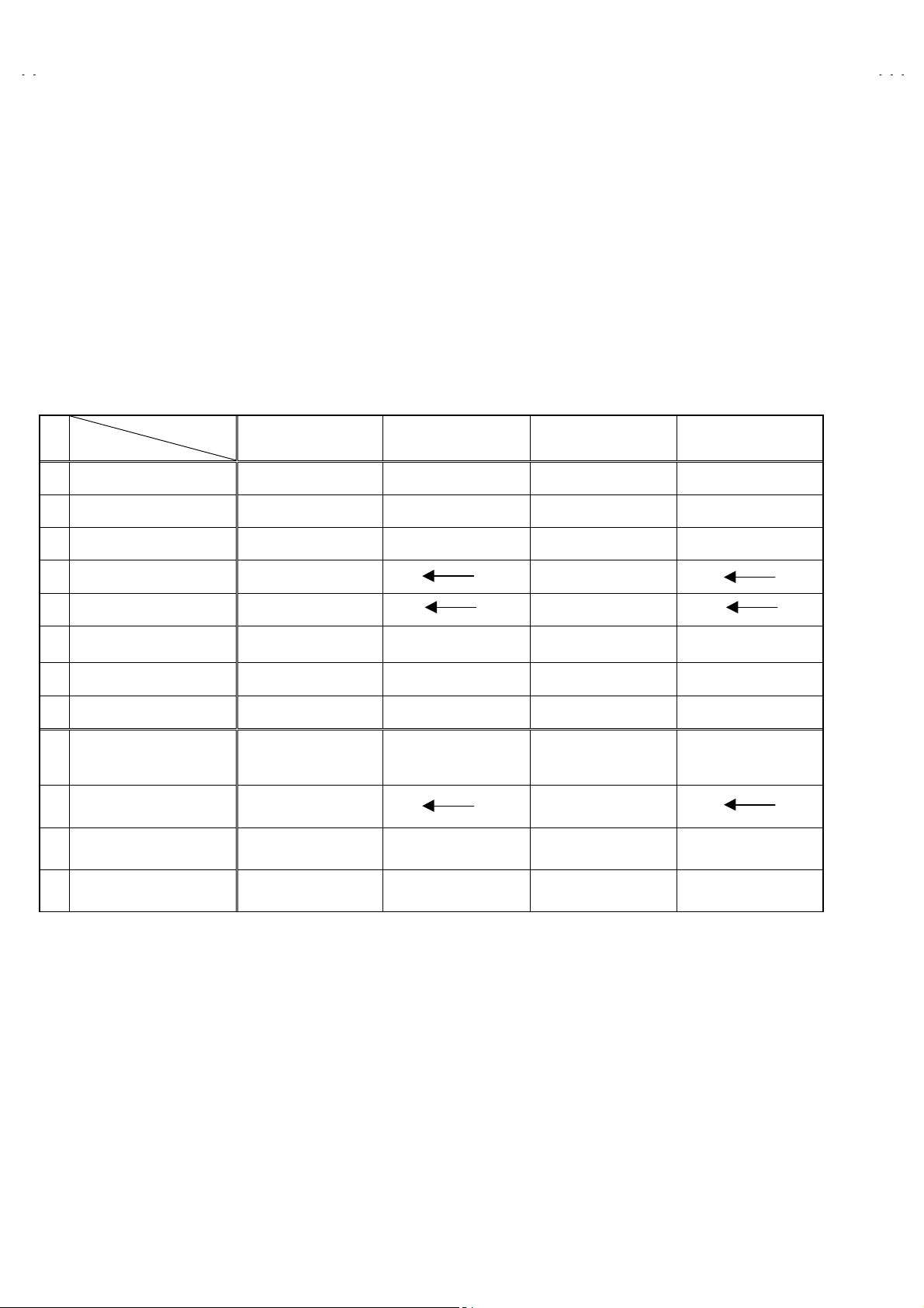
TABLE 1(System Constant Setting)
Setting value
Setting item Setting content
VIDEO 1 2
AUDIO MONO MTS
MONO MONO MTS
12
AV-21D13
AV-20N13
/PH
/PH
AV-21D33
AV-20N33
V-21D13
V-21D33
V-20N13
V-20N33
/PH
/PH
VARI. OUT NO NO
GAME YES YES
CINEMA YES YES
CCD YES YES
RETURN+ YES YES
SURROUND NO YES
YES NO
YES NO
YES NO
YES NO
YES NO
YES NO
TABLE 2 (User setting value)
Setting item Setting value
" Setting of FUNCTION
MAIN POWER OFF
SUB POWER ON
CHANNEL CH 02 (AIR)
PICTURE BOOSTER OFF
VOLUME 10
TV/VIDEO TV
CAPTION OFF (CC1/T1)
DISPLAY POSITION INDICATION
SLEEP TIMER 0
VIDEO STATUS STANDARD
HYPER SURROUND OFF [ AV-21D33
COLOUR SYSTEM AUTO PAL
SETUP TOUR ON
" Setting of MENU
TINT
COLOR
PICTURE STANDARD
BRIGHT
DETAIL
BASS CENTER
TREBLE CENTER
BALANCE CENTER
MTS STEREO
SET CLOCK Unnecessary to set : (000)
ON/OFF TIMER NO
CHANNEL SUMMARY necessary to set
NOISE MUTING OFF
BACK GROUND BLACK
CLOSED CAPTION CC1 / T1 ( OFF at shipping )
LANGUAGE ENG.
[ AV-21D33
/PH
& AV-20N33
/PH
/PH
& AV-20N33
Only ]
/PH
Only ]
No.52022
13
Page 14

A
V-21D13
A
A
A
V-21D33
V-20N13
V-20N33
INITIAL SETTING VALUE OF SERVICE MENU
1. Adjustment of the SERVICE MENU is made on the basis of the initial setting values; however, the new setting values which set the
screen in its optimum condition may differ from the initial setting.
2. Do not change the initial Setting Values of the Setting (Adjustment) items not listed In “ADJUSTM ENT”.
PICTURE MODE (1/2)
""""
" The four setting items in the video mode No.8 EXT PIC., No.9 EXT BRI., No.10 EXT COL. and No.11 EXT TINT are linked to the items in
the TV MODE No.1 PICTURE, No.2 BRIGHT, No.5 COL. NTSC and No.6 TINT, respectively. W hen the setting items in the TV mode are
adjusted, the values in the setting items in the video mode are revised automatically to the s ame values in the TV mode.(The initial setting
values given in ( ) ar e off-set values.)
" When the four items (No.8, 9, 10 and 11) are adjusted in the video mode, the setting values in each item are revised independently.
: Do not adjust in this area.
Initial setting value
No. Setting (Adjustment) item Variable range AV-21D13/PH
AV-21D33
1. PICTURE
2. BRIGHT
3. COL. PALM
4. COL. PALN
5. COL. NTSC
6. TINT
7. TV DTL
8. EXT PIC.
9. EXT BRI.
10. EXT COL.
11. EXT TINT
12. EXT DTL
13. P/N KILL 000 / 001 001 001
14. Y S CONT
15. TV Y-DL
16. EXR Y-DL
17. WPL SW 000 / 001
18. Y G AMMA 000 / 001
19. P/N G P. 000 / 001
20. COL. L SW 000 / 001
21. COL. LMT.
22. PN C. ATT
23. OFST. SW 000 / 001 000 000
24. OFSET. B-Y
25. OFSET. R-Y
26. C-TOF SW 000 / 001 001 001
27. TV T FO
28. TV T Q
29. EXT T FO
30. EXT T Q
31. C-TRAP 000 / 001
32. C-TR. FO
33. C-TRAP Q
34. FIX B/W 000 / 001
35. APA P. FO
36. DC TRAN.
37. B. ST. SW 000 / 001
38. B. ST. PO.
39. ABL GAIN
40. ABL PO.
000~127
000~127
000~127
000~127
000~127
000~127
000~063
±025
±025 (±005) (±005)
±025 (±000) (±000)
±025
000~063
000~031
000~007
000~007
000~003
000~003
000~015
000~015
000~003
000~003
000~003
000~003
000~003
000~003
000~003
000~007
000~001
000~007
000~007
(±000) (±000)
(+001) (+001)
/PH
064 070
064 060
070 070
070 070
073 072
068 065
033 033
035 035
031 031
001 001
002 002
000 000
000 000
000 000
001 001
001 001
001 001
008 008
008 008
001 001
000 000
000 000
000 000
000 000
002 002
000 000
000 000
001 001
007 007
000 000
000 000
004 004
000 000
AV-20N13/PH
AV-20N33
/PH
14
No.52022
Page 15

A
A
A
A
PICTURE MODE (2/2)
"
Initial setting value
No. Setting (Adjustment) item Variable range
41. HALF T.
42. DRV G SW 000 / 001 000 000
43. NT. COMB 000 / 001 001 001
44. COIN DET
45. NOISE L.
46. VCD MODE 000 / 001 000 000
47. V AGC SP 000 / 001 000 000
48. H POS. 50
49. H BLK. 50
50. V POS. 50
51. V SIZE50
52. V S CR50
53. V LIN . 50
54. H POS. 60
55. H BLK. 60
56. V POS. 60
57. V SIZE60
58. V S CR60
59. V LIN . 60
60. RF AGC
000~002
000~003
000~003
000~031
000~007
000~007
000~127
000~127
000~031
000~031
000~007
000~007
000~127
000~127
000~031
000~255
AV-21D13
AV-21D33
/PH
/PH
001 001
001 001
003 003
007 007
000 000
000 000
087 080
028 028
004 004
012 012
000 000
000 000
088 082
048 048
004 003
183 183
AV-20N13
AV-20N33
V-21D13
V-21D33
V-20N13
V-20N33
/PH
/PH
SOUND MODE
"
No. Setting (Adjustment) item Variable range Initial setting value
1. NOISE 000 / 001 001
2. IN LE VEL
3. FH MON. 000 / 001 000
4. ST VCO
5. PILOT 000 / 001 000
6. FILTER
7. LOW SEP.
8. HI SEP.
9. 5FH MON. 000 / 001 000
10. SAP VCO
11. IN GAIN 000 / 001 000
12. FIL. OFF.
VIDEO STATUS MODE
"
No. Setting (Adjustment) item Variable range
1. TINT
2. COLOR
3. PICTURE
4. BRIGHT
5. DETAIL
6. G DRIVE
7. B DRIVE
8. R CUT.
9. G CUT.
10. B CUT.
[ AV-21D33
& AV-20N33
/PH
Only ]
/PH
000~063
000~063
000~063
000~063
000~063
000~063
±010 (±000)
CINEMA GAME
±20 (±0) (±0)
±20 -3 -3
±20 -10 -10
±20 (±0) (±0)
±15 (±0) -5
-99~+50 -22 (±0)
-99~+50 -54 (±0)
±10 (±0) (±0)
±10 (±0) (±0)
±10 (±0) (±0)
020
025
030
022
023
026
Initial setting value
No.52022
15
Page 16

A
V-21D13
A
A
A
V-21D33
V-20N13
V-20N33
OTHERS MODE
"
No. Setting (Adjustment) item Variable range Initial setting value
1. OSD HP
2. OSD VP
3. H-CK SW 000 / 001 000
LOW LIGHT MODE
"
No. Setting (Adjustment) item Variable range Initial setting value
1. R CUTOFF
2. G CUTOFF
3. B CUTOFF
HIGH LIGHT MODE
"
No. Setting (Adjustment) item Variable range Initial setting value
1. G DRIVE
2. B DRIVE
RF AFC CHK MODE
"
No. Setting (Adjustment) item Variable range Initial setting value
000~031
000~015
000~255
000~255
000~255
000~255
000~255
023
012
020
020
020
128
128
1. RF AFC ON / OFF ON
2. FINE
2
C BUS CTRL MODE
I
"
No. Setting (Adjustment) item Variable range Initial setting value
1. I2C BUS ON / OFF [Fixed ON]
-77~+77
± **
(DO NOT ADJUST)
16
No.52022
Page 17

A
A
A
A
SERVICE ADJUSTMENTS
ADJUSTMENT PREPARATION
1. You can make the necessary adjust ments for this unit with
either the Remote Control Unit or With the adjustment tools
and parts as given belo w.
2. Adjustment with the Remote Control Unit is made on the
basis of the initial setting values, however, the new setting
values which set the screen to its optimum condition may
differ from the initial settings.
3. Make sure that connection is correctly made to AC power
source.
4. Turn on t he power of the set and equipment before use, and
start the adjustment procedures after waiting at least 30 minutes.
5. Unless otherwise specified, prepare the most suitable reception
or input signal for adjustment.
6. Never touch any adjustment parts, which are not specified
in the list for this adjustment VRs, transforms, condensers,
etc.
7. Preparation for adjustment
Unless otherwise specified in the adjustment instructions, pr eset
the following functions with the REMOTE CONTROL UNIT.
User mode position
VIDEO STATUS STANDARD
TINT / COLOUR
/ PICTURE / BRIGHT
/ DETAIL
BASS / TREBLE
/ BALANCE
MTS
HYPER SURROUND
STANDARD
CENTER
[AV-21D33
STEREO
[AV-21D33
OFF
[AV-21D33
V-21D13
V-21D33
V-20N13
V-20N33
/PH
& AV-20N33
/PH & AV-20N33/PH]
/PH
& AV-20N33
/PH
/PH
]
]
SETUP TOUR ON
ADJUSTMENT EQUIPMENT
1. DC voltmeter (or digital voltmeter)
2. Oscill oscope
3. Signal generator (Pattern generator) [NTSC / PAL-M / PAL-N ]
4. Remote contr ol unit
5. TV audio multiplex signal generator.
6. Frequ ency c ounter.
ADJUSTMENT ITEMS
Adjustment item Adjustment item
B1 POWER SUPPLY
IF VCO adjustment VIDEO / CHROMA adjustment
RF AGC adjustment
FOCUS adjustment PURITY / CONVERGENCE adjustment.
DEFLECTION adjustment
MTS circuit adjustment [AV-21D33
/PH
& AV-20N33
/PH
]
No.52022
17
Page 18

A
V-21D13
A
A
A
V-21D33
V-20N13
V-20N33
BASIC OPERATION IN SERVICE MENU
1. TOOL OF SERVICE MENU OPERATION
Operate the SERVICE MENU with the REMOTE CONTROL UNIT.
2. SERVICE MENU ITEMS
In general basic setting (adjustments) items or ver ifications are performed in the SERVICE MENU.
(1) PICTURE・・・・・・・・・・・・・・・・・・・ This set the setting values (adjustment values) of the VIDEO/CHROMA and DEFLECTION circuits.
(2) SOUND ・・・・・・・・・・・・・・・・・・・・ This set the setting values (adjustment values) of the AUDIO circuit.[AV-21D33
(3) VIDEO STATUS ・・・・・・・・・・・・・ This is used when the THEATER and GAME MODE is adjust ed.
(4) OTHERS ・・・・・・・・・・・・・・・・・・・ This is us ed when the OT HERS MODE is adjusted.
(5) LOW LIGHT・・・・・・・・・・・・・・・・・ This sets the setting values (adjustment values) of the W HITE BALANCE circuit.
(6) HIGH LIGHT ・・・・・・・・・・・・・・・・ This sets the setting values (adjustment values) of the WHITE BALANCE circuit.
(7) RF AFC CHK・・・・・・・・・・・・・・・・ This is us ed when the RF AFC CHK MODE is verified. [Do not adjust]
(8) VCO (CW) ・・・・・・・・・・・・・・・・・・ This is used when the IF VCO is adjusted.
2
(9) I
C BUS CTRL・・・・・・・・・・・・・・・ This is us ed when ON/OFF of the I2C BUS CTRL is set. [Fixed ON]
(10)
SETUP TOUR OFF・・・・・・・・・・ It should be able to select mode (LANGUAGE and SET CLOCK).
[Should be OFF]
3. Basic Operations of the SERVIC E MENU
(1) How to enter the SERVICE MENU.
Press the DISPLAY key and VIDEO STATUS key of the remote control unit
at the s ame time to enter the SERVICE MENU screen ①
shown in figure page later.
(2) SERVICE MENU screen selection
Press the UP / DOWN key of the MENU to select any of the
following items.
SERVICE MENU
PICTURE SOUND
VIDEO STATUS OTHERS
LOW LIGHT HIGH LIGHT
RF AFC CHK
VCO (CW) I2C BUS CTRL
SETUP TOUR(OFF)
SELECT BY
OPERATE BY
(The letters of the selected items are displayed in yellow.)
/PH & AV-20N33/PH]
EXIT BY
EXIT
IT
(3) Enter the any setting ( adjustment ) mode
" PICTURE, SOUND and OTHERS mode
AV-21D33
AV-20N33/PH
1) If select any of PICTURE, SOUND or OTHERS items, and the LEFT / RIGHT key is pressed from SERVICE MENU ( MAIN
MENU ), the screen ② will be displayed as shown in figure page later.
2) Then the UP / DOW N key is pressed, the PICTURE mode screen ③ or the SOUND mode screen ④ or the OTHERS mode
screen ⑤ is displayed, and the PICTURE, SOUND or OTHERS setting can be performed.
" VIDEO STATUS, LOW LIGHT, HIGH LIGHT, RF AFC CHK, VCO (CW) and I
1) If select any of VIDEO STATUS / LOW LIGHT / HIGH LIGHT / RF AFC CHK / VCO (CW) / I
2
C BUS CTRL mode
2
C BUS CTRL items, and t he LEFT
/ RIGHT key is pressed from SERVICE MENU ( MAIN MENU ), the screens ⑥ ⑦ ⑧ ⑨ ⑩ ⑪ will be displayed as shown in
figure page later.
2) Then the settings or verifications can be performed.
" SETUP TOUR OFF mode
1) If select of SETUP TOUR OFF item from SERVICE MENU , and you can change the ON or OFF(should be OFF).
(Should be OFF)
% If it is ON, then you turn the TV power off, when you are turn the TV power on again.
The JVC is logo will be shown about 15 seconds automatic ally.
2) MENU -/+ Key ・・・・・・・・・・・・・ Select Language.
3) MENU ▼ Key・・・・・・・・・・・・・ Auto Search.
/PH
Only
18
No.52022
Page 19

A
A
A
A
(4) Setting method
1) UP / DOW N key of the MENU
Select the SETTING ITEM.
2) LEFT / RIGHT key of the MENU
Setting (adjust) the SETTING VALUE of the SETTING ITEM.
When the key is released the SETT ING VALUE will be stored
(memorized).
3) EXIT key
Returns to the previous scr een.
[NOTE] (PICTURE MODE ONLY)
When the INITIAL SETTING VALUE is turned to yellow, you can adjust the
values but you cannot adjust the values when it is turned to red.
(Becaus e the signal conditions, etc. are not met.)
(5) Releasing SERVICE MENU
1) After returning to the SERVICE MENU upon completion of the setting
(adjustment) work, press the EXIT key again.
SETTING
ITEM
1. PICTURE
********
******** ****
****************
SELECT BY
OPERATE BY
SETTING
VALUE
***
***
******
****
********
EXIT BY
EXIT
PICTURE MODE
1. NOISE
STATUS
********
********
******** ********
SELECT BY
OPERATE BY
***
***
******
EXIT BY
EXIT
V-21D13
V-21D33
V-20N13
V-20N33
IT
IT
★ The s ettings for LOW LIGHT and HIGH LIGHT are described in the W HITE
BALANCE page of ADJUSTMENT.
★ The setting for VCO (CW ) are described in the IF VCO page of ADJUSTMENT .
The letter of the
selected
Items are displayed in yellow.
CINEMA
TINT G DRIVE
COLOR B DRIVE
PICTURE R CUT.
BRIGHT G CUT.
DETAIL B CUT.
SELECT BY
OPERATE BY
***
*** ***
******
***
*** ***
******
***
*** ***
******
***
*** ***
******
***
*** ***
******
EXIT BY
EXIT
***
******
***
******
***
******
***
******
***
******
Press
VIDEO
STAT US
Key
[ AV-21D33
SELECT BY
OPERATE BY
/PH &
1. OSD HP
AV-20N33
OTHERS MODE
GAME
SOUND MODE
TINT G DRIVE
COLOR B DRIVE
PICTURE R CUT.
BRIGHT G CUT.
DETAIL B CUT.
SELECT BY
OPERATE BY
***
*** ***
******
***
*** ***
******
***
*** ***
******
***
*** ***
******
***
*** ***
******
/PH
***
***
******
EXIT BY
EXIT
EXIT BY
EXIT
***
******
***
******
***
******
***
******
***
******
IT
Only ]
VIDEO STATUS MODE
No.52022
19
Page 20

A
V-21D13
A
A
A
V-21D33
V-20N13
V-20N33
SERVICE MENU FLOW CHART
SERVICE MENU (MAIN MENU)
①
①
① ①
SERVICE MENU
PICTURE SOUND
VIDEO STATUS OTHERS
LOW LIGHT HIGH LIGHT
RF AFC CHK
VCO (CW) I2C BUS CTRL
SETUP TOUR OFF
SELECT BY
OPERATE BY
AV-21D33/PH
ON / OFF
⑧
⑧
⑧ ⑧
RF AFC CHK MODE
⑨
⑨
⑨ ⑨
AV-20N33/PH
HIGH LIGHT MODE
HIGH LIGHT
***
*** ***
******
EXIT BY
EXIT
***
******
EXIT BY
EXIT
DO NOT ADJUST
Only
SCREEN
②
②
② ②
SELECT BY EXIT BY
AV-21D33/PH
SOUND MODE
④
④
④ ④
1. NOISE
STATUS
SELECT BY
OPERATE BY
AV-20N33/PH
***
***
******
********
********
****************
EXIT BY
EXIT
EXIT
Only
PICTURE MODE
③
③
③ ③
1. PICTURE
********
******** ****
****************
SELECT BY
OPERATE BY
OTHERS MODE
⑤
⑤
⑤ ⑤
1. OSD HP
SELECT BY
OPERATE BY
***
***
******
****
********
EXIT BY
EXIT
***
***
******
EXIT BY
EXIT
RF AFC ON
FINE
SELECT BY
OPERATE BY
VCO (CW) MODE
⑩
⑩
⑩ ⑩
TOO HIGH
ABOVE REFERENCE
BELOW REFERE NCE
TOO LOW
SYNC : YES
I2C BUS CTRL MODE
⑪
⑪
⑪ ⑪
I2C BUS ON
OPERATE BY
***
***
******
EXIT BY
EXIT
EXIT BY
EXIT
FIXED ON
EXIT BY
EXIT
VIDEO STATUS MODE
⑥
⑥
⑥ ⑥
CINEMA
TINT G DRIVE
COLOR B DRIVE
PICTURE R CUT .
BRIGHT G CUT.
DETAIL B CUT.
SELECT BY
IT
OPERATE BY
BRIGHT
***
*** ***
******
***
*** ***
******
***
*** ***
******
***
*** ***
******
***
*** ***
******
EXIT BY
LOW LIGHT MODE
⑦
⑦
⑦ ⑦
BRIGHT
***
*** *** ***
*** ***
***
***
******
*** ***
*** ****** ***
EXIT BY
EXIT
EXIT
***
******
***
******
***
******
***
******
***
******
Press
VIDEO
STATUS
Key
GAME
TINT G DRIVE
COLOR B DRIVE
PICTURE R CUT.
BRIGHT G CUT.
DETAIL B CUT.
SELECT BY
OPERATE BY
***
*** ***
******
***
*** ***
******
***
*** ***
******
***
*** ***
******
***
*** ***
******
EXIT BY
EXIT
***
******
***
******
***
******
***
******
***
******
20
No.52022
Page 21

A
A
A
A
ADJUSTMENT LOCATIONS
V-21D13
V-21D33
V-20N13
V-20N33
FRONT
DEG
S901
POWER
SW
TOP
MAIN PWB
PW
F901
CRT SOCKET PWB
(SOLDER SIDE)
TP-47B
T
E1
TP-E( )
IC701
MEMORY IC
T
(Within MAIN PW B)
U
CRT EARTH
(BRAIDED ASS'Y)
AV-21D13/PH & AV-20N13/PH
IC704
AV IN
S
AV-21D33/PH & AV-20N33/PH
[AV-21D33/PH & AV-20N33/PH Only]
AV-21D33/PH & AV-20N33/PH
AV-21D13/PH & AV-20N13/PH
IC201
MPX
AV IN/OUT
CW
15
T111
HV
U
HVT
B1
1
3
ANT
1Pin B1(TP-91)
3Pin TP-E( )
UPPER:F OCUS
LOWER:SCREEN
No.52022
21
Page 22

A
V-21D13
A
A
A
V-21D33
V-20N13
V-20N33
ADJUSTMENTS
■■■■
B1 POWER SUPPLY
Item
Check of
B1 POWER
SUPPLY
Measurin g
instrument
DC Voltmeter B1 (
IF VCO ADJUSTMENT
Item
IF VCO
adjustment
Measurin g
instrument
Signal
generator
TOO HIGH
ABOVE REFERENCE
BELOW REFERENCE
TOO LOW
SYNC : YES
Test point Adjustment item Description
B1
Connector
pin)
1
(TP-91)
TP-E(#)
(
B1
Connector
pin)
3
Test point Adjustment item Description
CW TRANSF. (T111)
[ VCO (CW) ] mode
YELLOW
EXIT BY
EXIT
IT
1. Receive a black and whit e signal (c olor off). (NTSC)
2. Connect a DC voltmeter to TP-91(B1) and TP-E(#).
3. Confirm that the voltage is DC134.5V±2V.
" Under normal conditions, no adjustment is required.
1. Receive a broadc ast. (use channels without offset frequenc y).
2. Select the VCO(CW ) mode from the SERVICE MENU.
3. Confirm the color change (yellow) from TOO HIGH to TOO
LOW by CW TRANSF.(T111) and SYNC : YES being shown
on the screen. Then, adjust CW TRANSF.(T111) until BELOW
REFERENCE mark tur ns yellow and confirm again S YNC :
YES being shown on the screen.
RF AGC ADJUSTMENT
RF AGC
adjustment
Initial setting value
No. Setting item
60 RF AGC 183 183
AV-21D13
AV-21D33
/PH
/PH
FOCUS ADJUSTMENT
FOCUS
adjustment
Signal
generator
No.60 RF AGC 1. Receive a broadcast.
2. Select No.60 RF AGC of the PICTURE mode in SERVICE
MENU.
3. Press the MUTE key and turn off c olor.
4. With the MENU LEFT key, get noise in the screen picture. (0
side of setting value)
AV-20N13
AV-20N33/PH
FOCUS VR
[ In HVT ]
/PH
5. Press the MENU RIGHT key and stop when noise dis appears
from the screen.
6. Change to other channels and make sure that there is no
irregularity.
7. Press the MUTE key and get c olor out.
1. Receive a cross hatch signal.
2. While looking at the scr een, adjust FOCUS VR so that the
vertical and horizontal lines will be clear and in fine detail.
3. Make sure that the picture is in focus even when the screen
gets darkened.
22
No.52022
Page 23

A
A
A
A
DEFLECTION ADJUSTMENT
V-21D13
V-21D33
V-20N13
V-20N33
Item
Measurin g
Test point Adjustment item Description
instrument
V. HEIGHT,
V. POSITION,
Signal
generator
V. LIN.
V. S CR
adjustment
Initial setting value
No. Setting item
AV-21D13
/PH
AV-21D33/PH
56 V POS.60 000 000
57 V SIZE 60 088 082
58 V S CR60 048 048
59 V. LIN60 004 003
Scree size
Screen
size
(92%)
No.57 V SIZE 60
No.58 V S CR60
No.59 V. LIN. 60
AV-20N13/PH
AV-20N33/PH
No.50 V POS.50
No.51 V SIZE 50
No.52 V S CR50
No.53 V LIN.50
Picture
size
(100%)
[60Hz]No.56 V POS. 60
1. Receive a crosshatch signal.(NTSC or PAL-M)
2. Confirm that the value of PICTURE MODE No.56 V POS. 60 is
0.
3. Confirm the initial s etting value of the No.57 V SIZE 60, N o.58
V S CR60 and No.59 V LIN. 60.
4. Adjust the vertic al screen size to 92% with the P ICTURE
MODE No.57 V SIZE60.
5. Adjust the PICT URE MODE No.59 L LIN. 60 and No.58 V S
CR60 to get the best vertical linearity.
NOTE :
The PICTURE MODE No.56 V POS. 60 is fixed on value 0.
[50Hz]
1. Receive a crosshatch signal. (PAL-N)
2. Confirm the initial setting value of the No.50 V POS.50, No.51
V SIZE 50, No.52 V S CR 50 and No.53 V LIN.50.
3. Adjust the vertic al screen size to 92% with the P ICTURE
MODE No.51 V SIZE50.
4. Adjust the PICTURE MODE No.53 V LIN.50 and No.52 V S
CR50 to get the best vertical linearity.
5. Adjust the PICTURE MODE No.50 V POS.50 so that the
vertical center line c omes close to the CRT vertic al center as
much as possible.
" Readjust V SIZE, V LIN., V S CR if necessar y.
Initial setting value
No. Setting item
AV-21D13/PH
AV-21D33
/PH
AV-20N13
AV-20N33
/PH
/PH
(100%)
H. POSITION
adjustment
Picture size
Signal
generator
Initial setting value
No. Setting item
AV-21D13
/PH
AV-21D33/PH
54 H POS.60 012 012
Initial setting value
No. Setting item
AV-21D13
AV-21D33
/PH
/PH
48 H POS.50 007 007
AV-20N13
/PH
AV-20N33/PH
No.48 H POS.50
AV-20N13
AV-20N33
/PH
/PH
50 V POS.50 000 000
51 V SIZE 50 087 080
52 V S CR50 028 028
53 V LIN.50 004 004
[60Hz]No.54 H POS.60
1. Receive a cross hatch signal. (NTSC or PAL-M)
2. Select the No.54 H POS. 60 of the PICTURE mode in
SERVICE MENU.
3. Confirm the initial s etting value of the No.54 H POS. 60.
4. Adjust the No.54 H POS. 60 until the screen will be horizontally
centered.
[50Hz]
1. Receive a cross hatch signal. (PAL-N)
2. Select the No.48 H POS. 50 of the PICTURE mode in
SERVICE MENU.
3. Confirm the initial s etting value of the No.48 H POS. 50.
4. Adjust the No.48 H POS. 50 until the screen will be horizontally
centered.
No.52022
23
Page 24

A
V-21D13
A
A
A
V-21D33
V-20N13
V-20N33
VIDEO / CHROMA ADJUSTMENT
Item
WHITE
BALANCE
(Low Light)
adjustment
Measurin g
Test point Adjustment item Description
instrument
Signal
generator
Remote
control unit
[LOW LIGHT] MODE
R CUTOFF
G CUTOFF
BRIGHT
***
BRIGHT
BRIGHT
Remote Control Unit
H.LINE ON
1 2
R CUTOFF
4 5
R CUTOFF
7 8
***
******
*** *** ***
*** *** ***
*** *** ****** *** ***
H.LINE OFF
G CUTOFF
G CUTOFF
B CUTOFF
EXIT BY
EXIT
EXIT
3
B CUTOFF
6
B CUTOFF
9
BRIGHT
R CUTOFF
G CUTOFF
B CUT OFF
SCREEN VR
IT
1. Receive a black and whit e signal (c olor off).
2. Select t he LOW LIGHT mode from the SERVIC E MENU.
3. Confirm the Initial setting value of BRIGHT, R CUTOFF, G
CUTOFF and B CUTOFF.
4. Display a single horizontal line by pressing t he ①①①① key of the
remote c ontrol unit.
5. Turn the screen VR all the way to the left.
6. Turn the screen VR gradually to the right fr om the left until
either one of the red, blue or green c olors appears faintly.
7. Adjust the two colors which did not appear until the single
horizontal line that is displayed becomes white using the ④④④④ to
⑨⑨⑨⑨ keys of the remote control unit.
8. Turn the screen VR to where the single horizontal line glows
faintly.
9. Press the ②②②② key to return to the regular screen.
Initial setting value
No. Setting item
AV-21D13
/PH
AV-21D33/PH
AV-20N13
/PH
AV-20N33/PH
2BRIGHT 064 060
1R CUTOFF 020 020
2G CUTOFF 020 020
3B CUTOFF 020 020
WHITE
BALANCE
(High Light)
adjustment
Signal
generator
Remote
control unit
[HIGH LIGHT] MODE
G DRIVE
B DRIVE
HIGH LIGHT
***
******
***
******
******
EXIT BY
EXIT
G DRIVE
B DRIVE
IT
1. Receive a black and whit e signal (c olor off).
2. Select the HIGH LIGHT mode in the SERVICE MENU.
3. Confirm the initial s etting value of G DRIVE and B DRIVE.
4. Adjust the screen color to white with the⑤⑤⑤⑤, ⑥⑥⑥⑥, ⑧⑧⑧⑧ and ⑨⑨⑨⑨
keys of the remote control unit.
Remote Control Unit
H.LINE ON
H.LINE OFF
1 2
G DRIVE
4 5
G DRIVE
7 8
EXIT
3
B DRIVE
6
B DRIVE
9
Initial setting value
No. Setting item
AV-21D13
AV-21D33
/PH
/PH
AV-20N13
AV-20N33
/PH
/PH
1 G DRIVE 128 128
2B DRIVE 128 128
24
No.52022
Page 25

A
V-21D13
A
A
A
V-21D33
V-20N13
V-20N33
Item
SUB BRIGHT
adjustment
Measurin g
instrument
Remote
control unit
Test point Adjustment item Description
No.2 BRIGHT 1. Receive a broadcast.
Initial setting value
No. Setting item
AV-21D13
/PH
AV-21D33/PH
AV-20N13
AV-20N33/PH
2BRIGHT 064 064
SUB
CONTRAST
Remote
control unit
No.1 PICTURE 1. R eceive a broadc ast.
adjustment
Initial setting value
No. Setting item
AV-21D13
AV-21D33
/PH
/PH
1PICTURE 064 070
SUB COLOR
Adju stment
Remote
control unit
[ⅠⅠⅠⅠ]
AV-20N13
AV-20N33
/PH
/PH
/PH
2. Select No.2 BRIGHT of the PICTURE mode in SERVICE
MENU.
3. Confirm the initial s etting value of the No.2 BRIGHT.
4. If the brightness is not the best with the initial setting value,
make fine adjustment of the No.2 BRIGHT until you get the
optimum brightness.
2. Select No.1 PICTURE of the PICTURE mode in SERVICE
MENU.
3. Confirm the initial s etting value of the No.1 PICTURE.
4. If the contrast is not the best with the initial setting value, make
fine adjustment of the No.1 PICTURE until you get the
optimum contrast.
[PAL-M]No.3 COL. PALM
1. Receive a PAL-M broadcast.
2. Select No.3 COL. PALM of the PICTURE mode in SERVICE
MENU.
3. Confirm the initial s etting value of the No.3 COL. PALM.
4. If the color is not the best with the initial s etting value, make
fine adjustment until you get the best color.
Initial setting value
No. Setting item
COL.PALM 070 070
3
COL.PALN 070 070
4
COL.NTSC
5
AV-21D13
AV-21D33
/PH
/PH
072 072
AV-20N13
AV-20N33
No.5 COL. NTSC
SUB TINT
adjustment
Remote
control unit
No. 6 TINT 1. Receive a NTSC color bar signal.
[ⅠⅠⅠⅠ]
No.
Setting item
Initial setting value
AV-21D13
AV-21D33
/PH
/PH
AV-20N13
AV-20N33
6TINT 068 065
/PH
/PH
/PH
/PH
[PAL-N]No.4 COL. PALN
1. Receive a PAL-N broadc ast.
2. Select No.4 COL. PALN of the PICTURE mode in SERVICE
MENU.
3. Confirm the initial s etting value of the No.4 COL. PALN.
4. If the color is not the best with the initial s etting value, make
fine adjustment until you get the best color.
[NTSC]
1. Receive a NTSC broadcast.
2. Select No.5 COL. NTSC of the PICTURE mode in SERVICE
MENU.
3. Confirm the initial s etting value of the No.5 COL. NTSC.
4. If the color is not the best with the initial s etting value, make
fine adjustment until you get the best color.
2. Select No. 6 TINT of the PICTURE mode in SERVECE MENU.
3. Confirm the initial s etting value of the No. 6 TINT.
4. If the tint is not the best with the initial setting value, make fine
adjustment until you get the best tint.
No.52022
25
Page 26

A
V-21D13
A
A
A
V-21D33
V-20N13
V-20N33
Item
Adju stment
of SUB
COLOR-ⅡⅡⅡⅡ
W
Y
Cy
Measurin g
instrument
" Signal
generator
" Oscillo-
scope
" Remote
control
unit
G
R
Mg
Test point Adjustment item Description
TP-47B
TP-E(####)
[ CRT
SOCKET
PWB ]
( )
0V
(+)
(A)
3. COL. PALM
[Method of adjustment using measuring instrument]
(PAL-M COLOR)
1. Receive a PAL-M full field color bar signal (75% white).
2. Select the sub menu screen PICT URE from the SERVICE
MENU.
3. Select 3. COL. PALM with the MENU / key , and confirm
its initial setting value.
4. Connect the oscillosc ope between TP-47B and TP-E.
5. Adjust 3. COL. PALM to set the value (A) in the figure to +3V
(W & B), with the MENU -/+ key.
(PAL-N COLOR)4. COL. PALM
1. Receive a PAL-N full field color bar signal (75% white).
2. In the sub menu screen PICTURE, select 4. COL. PALN with
the MENU / key, and c onfirm its initial setting value.
3. Connect the oscillosc ope between TP-47B and TP-E.
4. Adjust 4. COL. PALN to set the value (A) in the figure to
+11V(W & B), with the MENU -/+ key.
B
5. COL. NTSC
(NTSC COLOR)
1. Receive a NTSC full field color bar signal (75% white).
2. In the sub menu screen PICTURE, select 5. COL. NTSC with
the MENU / key, and c onfirm its initial setting value.
3. Connect the oscillosc ope between TP-47B and TP-E.
4. Adjust 5. COL. NTSC to set the value (A) in the figure to the
voltage shown in the table bellow with the MENU -/+ key
of
SUB TINT-ⅡⅡⅡⅡ
W
Y
Cy
" Signal
generator
" Oscillo-
scope
Remote
control
unit
G
Mg
R
B
TP-47B
TP-E(####)
[ CRT
SOCKET
PWB ]
( )
0V
(+)
(B)
W-B
Models
AV-21D13
AV-21D33
AV-20N13
AV-20N33
[Method of adjustment using measuring instrument]Adju stment
6.TINT 1. Receive a NTSC 3.58 c olor bar signal (full field color bar
75%white).
2. Select the sub menu screen PICT URE from the SERVICE
MENU.
3. Select 6. TINT with the MENU / key, and confirm its initial
setting value.
4. Connect the oscillosc ope betweenTP-47B and TP-E.
5. Adjust 6. TINT to set the value (B) in the figur e to the voltage
shown in the table bellow with the MENU -/+ key.
W- Mg
Models
AV-21D13
AV-21D33
AV-20N13
AV-20N33
/PH
/PH
/PH
/PH
/PH
/PH
/PH
/PH
Voltage
+15V
+13V
Voltage
+6V
+8V
26
No.52022
Page 27

A
A
A
A
VIDEO STATUS ADJUSTMENT ( Do not adjust. Each value should be set to the initial value. )
V-21D13
V-21D33
V-20N13
V-20N33
Item
Measurin g
instrument
Setting
of
Remote
control unit
VIDEO
STAT US
SUB MENU : VIDEO STATUS
GAME
TINT G DRIVE
COLOR B DRIVE
PICTURE R CUT.
BRIGHT G CUT.
DETAIL B CUT.
SELECT BY
OPERATE BY
Test point Adjustment item Description
***
*** ***
******
***
*** ***
******
***
*** ***
******
***
*** ***
******
***
*** ***
******
EXIT BY
EXIT
***
******
***
******
***
******
***
******
***
******
TINT
COLOR
PICTURE
BRIGHT
DETAIL
G DRIVE
B DRIVE
R CUT.
G CUT.
1. Select the sub menu screen VIDEO STATUS-CINEMA from
the SERVICE MENU.
2. Select TINT ~ B CUT. with the MENU / key, and reset
each value to the initial setting value with the MENU -/+
key.
3. Press the VIDEO STATUS key on the remote control unit to
select VIDEO STATUS-GAME. (Each time you press the
VIDEO ST ATUS key, CINEMA and GAME alternates.)
4. Make similar settings as in 2 above.
B CUT.
No. Setting item
1TINT
2 COLOR
3PICTURE
IT
4BRIGHT
5DETAIL
6 G DRIVE
7B DRIVE
8R CUT.
9G CUT.
10 B CUT
Variable
Range
CINEMA
±20 (±0) (±0)
±20
-30~+20
-3 -3
-10 -10
±20 (±0) (±0)
±15 (±0) (±0)
-99~+50
-99~+50
-22 -5
-54
±10 (±0) (±0)
±10 (±0) (±0)
±10 (±0) (±0)
GAME
(±0)
No.52022
27
Page 28

A
V-21D13
A
A
A
V-21D33
V-20N13
V-20N33
MTS CIRCUIT ADJUSTMENT
[ AV-21D33
/PH
& AV-20N33
/PH
Only ]
Item
INPUT
LEVEL
check
STEREO VCO
adjustment
No. Setting item
2IN LEVEL 020 020
3FH MON 000 000
4ST VCO 025 025
SAP
VCO
adjustment
No. Setting item
95FH MON. 000 000
10 SAP VCO. 026 026
6FILTER 030 030
7 LOW SEP. 022 022
8 HI SEP. 063 063
Measurin g
instrument
Signal
generator
Frequency
counter
Signal
generator
Frequency
counter
Test point Adjustment part Description
R OUT
[AUDIO OUT]
Initial setting value
AV-21D13
AV-21D33/PH
MPX
Connector
4 pin SDA
3 pin GND
[MAIN PWB]
R OUT
[AUDIO OUT]
Initial setting value
AV-21D13
AV-21D33
No.2 IN LEVEL 1. Select the No.2 IN LEVEL of the SOUND mode in SERVICE
MENU.
2. Verify that the No.2 IN LEVEL is set at its initial setting value.
No.3 FH MON
No.4 ST VCO
/PH
AV-20N13/PH
AV-20N33/PH
No.9 5FH MON.
No.10 SAP VCO.
/PH
AV-20N13
/PH
AV-20N33
/PH
/PH
1. Receive a NTSC RF signal (non modulated sound signal) fr om
the antenna terminal.
2. Select the No.3 FH MON of SOUND mode in SERVICE
MENU, change the setting value from 0 to 1.
3. Connect the frequency connector to R OUT RCA pin of the
AUDIO OUT
4. Select the No.4 ST VCO.
5. Confirm the initial setting value of the No.4 ST VCO.
6. Adjust the No.4 ST VCO so that the frequenc y counter will
display 15.73kHz±0.1kH z.
7. Select the No.3 FH MON of the SOUND mode, and reset the
setting value from 1 to 0.
1. Receive a NTSC RF signal (non modulated sound signal) fr om
the antenna terminal.
2. Connect between pin 4 of MPX connector and GND (pin
3 of MPX connector) through 1MΩ resistor.
3. Select the No.9 5FH MON. of the SOUND mode in SERVICE
MENU, and reset the setting value from 0 to 1.
4. Connect the frequency connector to R OUT RCA pin of the
AUDIO OUT.
5. Select the No.10 SAP VCO.
6. Confirm the initial setting value of No.10 SAP VCO.
7. Adjust the No.10 SAP VCO so that the frequency c onnector
will display 78.67kHz±0.5kHz.
8. Select the No.9 5FH MON. of the SOUND mode, and reset the
setting value from 1 to 0.
FILTER
check
SEPARATION
adjustment
L-Channel
signal waveform
1 cycle
28
TV audio
multiplex
signal
generator
Oscilloscope
L OUT
R OUT
[AUDIO OUT]
R-Channel
crosstalk portion
Minimum
No.6 FILTER 1. Select the No.6 FILTER of the SOUND mode in SERVICE
MENU.
2. Verify that the No.6 FILTER is s et at its initial s etting value.
No.7 LOW SEP.
No.8 HI SEP.
1. Input a stereo L signal (300Hz) from the TV Audio multiplex
signal generator to the antenna terminal. (NTSC)
2. Connect an oscilloscope to L OUT RCA pin of the AUDIO
OUT, and display one c ycle portion of the 300Hz signal.
3. Change the connection of the oscilloscope to R OUT RCA pin
of the AUDIO OUT, and enlarge the voltage axis.
4. Select the No.7 LOW SEP. of the SOUND mode in SERVICE
MENU.
5. Confirm the initial setting value of the No.7 LOW SEP.
6. Adjust the No.7 LOW SEP. so that the stroke element of the
300Hz signal will become minimum.
7. Change the signal to 3kHz, and similarly adjust the “No.8 HI
SEP.
No.52022
Page 29

A
A
A
A
PURITY / CONVERGENCE ADJUSTMENT
PURITY ADJUSTMENT
1. Demagnetize CRT with the demagnetizer.
V-21D13
V-21D33
V-20N13
V-20N33
2. Loosen the retainer screw of the deflection yoke.
3. Remove the wedges.
4. Input a green raster signal from the signal generator, and turn
the screen to green raster.
5. Move the deflection yoke backward.
6. Bring the long lug of the purity magnets on the short lug and
position them horizontally. (Fig.2)
7. Adjust the gap between two lugs so that the GREEN RASTER
will come into the center of the screen. (Fig.3)
8. Move the deflection yoke forward, and fix the position of the
deflection yoke so that the whole screen will become green.
9. Insert the wedge to the top side of the deflection yoke s o that it
will not move.
WEDGE
CRT
# P/C MAGNETS
P : PURITY MAGNET
4 : 4 POLES
6 : 6 POLES
(convergence magnets)
(convergence magnets)
Fig.1
PURITY MAGNETS
DEFLECTION
YOKE
P
46
P / C
MAGNE TS
10. Input a crosshatch signal.
11. Verify that the scr een is horizontal.
12. Input red and blue raster signals, and make sure that purity is
properly adjusted.
Long lug
Short lug
(FRONT VIEW )
Bring the long lug over the short lug
and position them horizontally.
Fig.2
GREEN RASTER
CENTER
Fig.3
No.52022
29
Page 30

A
V-21D13
A
A
A
V-21D33
V-20N13
V-20N33
STATIC CONVERGENCE ADJUSTMENT
1. Input a crosshatch signal.
2. Using 4-pole convergence magnets, overlap the red and blue
lines in the center of the screen (Fig.1) and turn them to
magenta (red/blue).
3. Using 6-pole convergence magnets, overlap the
magenta(red/blue) and green lines in the center of the screen
and turn them to white.
4. Repeat 2 and 3 above, and make best convergence.
DYNAMIC CONVERGENCE ADJUSTMENT
1. Move the deflection yok e up and down and overlap the lines in
the periphery. (Fig. 2)
2. Move the deflection yok e left to right and overlap the lines in the
periphery. (Fig. 3)
3. Repeat 1 and 2 above, and make best convergence.
(FRONT VIEW )
(FRONT VIEW )
BLUE
GREEN
RED
RED
Fig.1
GREEN
BLUE
RED
GREEN
BLUE
●
After adjustment, fix the wedge at the original position.
Fast en the retainer screw of the deflection yoke.
Fix the 6 magnets with glue.
(FRONT VIEW )
GREEN
RED
BLUE
BLUE
GREEN RED
Fig.2
Fig.3
BLUE
GREEN
RED
RED
GREEN
BLUE
BLUE
GREEN
RED
30
No.52022
Page 31

A
A
A
A
HOW TO CHECK THE HIGH VOLTAGE HOLD DOWN CIRCUIT
1. HIGH VOLTAGE HOLD DOWN CIRCUIT
After repairing the high voltage hold down circ uit shown in Fig. 1.
This circuit shall be checked to operate correctly.
2. CHECKING OF THE HIGH VOLTAGE HOLD DOWN CIRCUIT
(1) Turn the POWER SW ON.
(2) As shown in Fig.2, set the resistor (between X connector 1 & 3 ).
(3) Make sure that the screen picture disappears.
(4) Temporarily unplug the power cord.
(5) Remove the resistor (between X connector 1 & 3 ).
(6) Again plug the power c ord, make sur e that the normal picture is displayed on the screen.
B1
Q52
2
Q94
2
Q941
H-Vcc
IC201
3
H-OUT
4
T521
V-21D13
V-21D33
V-20N13
V-20N33
T522
HVT
10
IC701
27 28
Q511
D510
3 2 1
R562
D562
R563
Fig. 1
RESISTOR
RESISTOR
RESISTORRESISTOR
17.2kΩ±1% 1/4W
17.2kΩ±1% 1/4W
17.2kΩ±1% 1/4W17.2kΩ±1% 1/4W
3 2 1 X
Q521
Fig.2
X
FR561
4
D561
C561
HEATER
CONNECTOR
R562
D562
R563
Fig. 2
No.52022
C561
FR561
D561
31
Page 32

A
V-21D13
A
A
A
V-21D33
V-20N13
V-20N33
SELF CHECK FUNCTIONS
1. Outline
This model includes protector functions f or Over-current, X-ray and CRT NECK which cutoff the sub-pow er in the event of a malfunction and
inform of the malfunction by flashing ON TIMER LED.
The malfunction is detected according to the state of the control line input connected to the main CPU.
2. Self check items
Check item Detected contents Detection method Abnormality state
Over-current protector An over-current on the B1 line
and Audio-Vcc line is detected.
[ AV-21D13/PH & AV-20N13/PH ]
An over-current on the B1 line is
detected.
[ AV-21D33/PH & AV-20N33/PH ]
X-ray protector Operation of X-ray protection
circuit
CRT NECK protector W hen the vertical circuit S-
correction capacitor C413 is
shorted, detect the potential
drop of the C413, and prevent
the burn damage to the CRT
NECK.
The main CPU detects at
1 second intervals.
If NG is detected f or more than
1 ms, a malfunction is interpreted.
The main CPU detects at
1 second intervals.
If NG is detected f or more than
1 ms, a malfunction is interpreted.
The main CPU detects at
1 second intervals.
If NG is detected f or more than
1 ms, a malfunction is interpreted.
During an abnormality the subpower is cutoff. The remote
controller power key operation is
not recognized and sub-power
off is maintained until the power
cord is unplugged and
reinserted.
During an abnormality the subpower is cutoff. The remote
controller power key operation is
not recognized and sub-power
off is maintained until the power
cord is unplugged and
reinserted.
During an abnormality the subpower is cutoff. The remote
controller power key operation is
not recognized and sub-power
off is maintained until the power
cord is unplugged and
reinserted.
3. Self check indicating function
The self check function begins detection about 5
seconds aft er power is supplied.
In the event a malfunction is detected, the sub-power is
cutoff immediately.
At this time, the ON TIMER LED flashes to inform of
the malfunction.
Item LED ON / OFF intervals Priority of detection
OCP/X-ray every 0.5-second 1
NECK every 1.0-second 2
32
POWER
supplied
No.52022
About 5 seconds
after
Detection
start
Malfuction is
detected
SUB-POWER OFF
Flashing
ON TIMER LED
Page 33

A
A
A
A
REPLACEMENT OF CHIP COMPONENT
! CAUTIONS
1. Avoid heating f or more than 3 s econds.
2. Do not rub the electrodes and the resist parts of the pattern.
3. When removing a chip part, melt the solder adequately.
4. Do not reuse a chip part after removing it.
! SOLDERING IRON
1. Use a high insulation soldering iron with a thin pointed end of it.
2. A 30w s oldering iron is recommended for easily removing parts.
! REPLACEMENT STEPS
1.
How to remove Chip parts
$ Resistors, capacitors, etc.
(1) As shown in the figure, push the part with tweezers and
alternately melt the solder at each end.
V-21D13
V-21D33
V-20N13
V-20N33
2. How to install Chip parts
$ Resistors, capacitors, etc.
(1) Apply solder to the pattern as indicated in the figure.
(2) Shift with tweezers and remove the chip part.
$ Transistors, diodes, variable resistors, etc.
(1) Apply extra s older to each lead.
SOLDER
(2) As shown in the figure, push the part with tweezers and
alternately melt the solder at each lead. Shift and remove
the chip part.
SOLDER
(2) Grasp the chip part with tweezers and place it on the
solder. Then heat and melt the solder at both ends of the
chip part.
$ Transistors, diodes, variable resistors, etc.
(1) Apply solder to the pattern as indicated in the figure.
(2) Grasp the chip part with tweezers and place it on the
solder.
(3) First solder lead
(4) Then solder leads
as indicated in the figure.
A
A
B
C
and C.
B
A
B
Note
: After removing the part, remove remaining solder from
the pattern.
No.52022
C
33
Page 34

A
V-21D13
A
A
A
V-21D33
V-20N13
V-20N33
34
No.52022
 Loading...