

Page 1
SERVICE MANUAL
TV/DVD COMBO
AV-20FD24
AV-20FD24
POWER
TV CATV
DISPLAY
PLAY MODE
SLEEP
TIMER
AUDIO
AUDIO
TITLE
123
SUBTITLE
456
JUMP
789
C.C.
RETURN
ANGLE
0
MARKER ZOOM
REPEATA-BRETURN
–
SLOW
+
CANCEL
LIGHT
SELECT
MUTING
/ENTER
+
CH
VOL–VOL
INPUT
+
CH
–
DVD SETUP
TV MENU
DVD MENUTV/DVDNEXTPREV
B.SEARCH F.SEARCHPLAY
PAUSE/STILLSTOP
OPEN/CLOSE
TV / DVD
CONTENTS
q SPECIFICATIONS.............................................................................................................................................. 2
q OPERATING!INSTRUCTIONS!(APPENDIX)
q SAFETY!PRECAUTIONS .................................................................................................................................. 3
q SPECIFIC!SERVICE!INSTRUCTIONS .............................................................................................................. 7
q SERVICE!ADJUSTMENTS .............................................................................................................................. 19
q GUIDE!FOR!REPAIRING ................................................................................................................................. 25
q STANDARD!CIRCUIT!DIAGRAM ................................................................................................................... 2-1
q PARTS!LIST ..................................................................................................................................................... 37
COPYRIGHT © 2003 VICTOR COMPANY OF JAPAN, LTD.
No. 52133
2003/06
Page 2

AV-20FD24
SPECIFICATIONS
TELEVISION
Picture Tube: 20” (measured diagonally)
Color System: NTSC
TV RF System: US System M
Tuner Type: Quartz PLL Frequency Synthesized
Receiving Channels: VHF 2-13
UHF 14-69
CATV 14-36 (A)-(W)
37-59 (AA)-(WW)
60-85 (AAA)-(ZZZ)
86-94 (86)-(94)
95-99 (A-5)-(A-1)
100-125 (100)-(125)
01 (5A)
Intermediate Frequency: Picture (FP) : 45.75 MHz
Sound (FS) : 41.25 MHz
FP-FS : 4.50 MHz
Antenna Input: VHF/UHF In 75 ohms coaxial, F-Type Connector
Speaker: 1.8” x 3.9”, 8 ohms x 2
Audio Output Power: 2.5 W + 2.5 W
DVD/CD!PLAYER
Color System: NTSC
Applicable Disc: DVD (120 mm, 80 mm)
CD-DA (120 mm, 80 mm)
CD-R/RW (120 mm, 80 mm)
Pick up: 1-Lens, 2-Beams System
CD : Wavelength : 775 - 815 nm
Maximum output power : 0.5 mW
DVD : Wavelength : 650 - 666 nm
Maximum output power : 2.0 mW
Frequency Response: DVD : 4 Hz – 22 kHz
CD : 4 Hz – 20 kHz
Audio DAC: 192 kHz/24 bit
GENERAL
Power Source: 120 V AC, 60 Hz
Power Consumption: 115 Watts
Dimensions(W x H x D): 574 mm x 514.5 mm x 483 mm
Weight: 56.1 Ibs/25.5 kg
Inputs/Outputs: Video input: 1.0 Vp-p, 75 ohm (RCA pin jack)
Audio input: -8 dBm, 50 kohm (RCA pin jack)
Digital Audio output (DVD only): 0.5 Vp-p, 75 ohm (Coaxial)
Headphone Jack: 3.5 mm mini-jack
Storage Temperature -20 °C ~ 60 °C
Operating Temperature 5 °C ~ 40 °C
Accessories:
Remote Control X 1
Batteries (UM-3) X 2
Design!&!specification!are!subject!to!change!without!notice.
2
No. 52133
Page 3
SAFETY!PRECAUTIONS
CAUTION
THIS DIGITAL VIDEO PLAYER EMPLOYS A LASER SYSTEM.
TO ENSURE PROPER USE OF THIS PRODUCT, PLEASE READ THIS SERVICE MANUAL CAREFULLY
AND RETAIN FOR FUTURE REFERENCE. SHOULD THE UNIT REQUIRE MAINTENANCE,
CONTACT AN AUTHORIZED SERVICE LOCATION-SEE SERVICE PROCEDURE.
USE OF CONTROLS, ADJUSTMENTS OR THE PERFORMANCE OF PROCEDURES OTHER THAN
THOSE SPECIFIED HEREIN MAY RESULT IN HAZARDOUS RADIATION EXPOSURE.
TO PREVENT DIRECT EXPOSURE TO LASER BEAM, DO NOT TRY TO OPEN THE ENCLOSURE.
VISIBLE LASER RADIATION MAY BE PRESENT WHEN THE ENCLOSURE IS OPENED. DO NOT
STARE INTO BEAM.
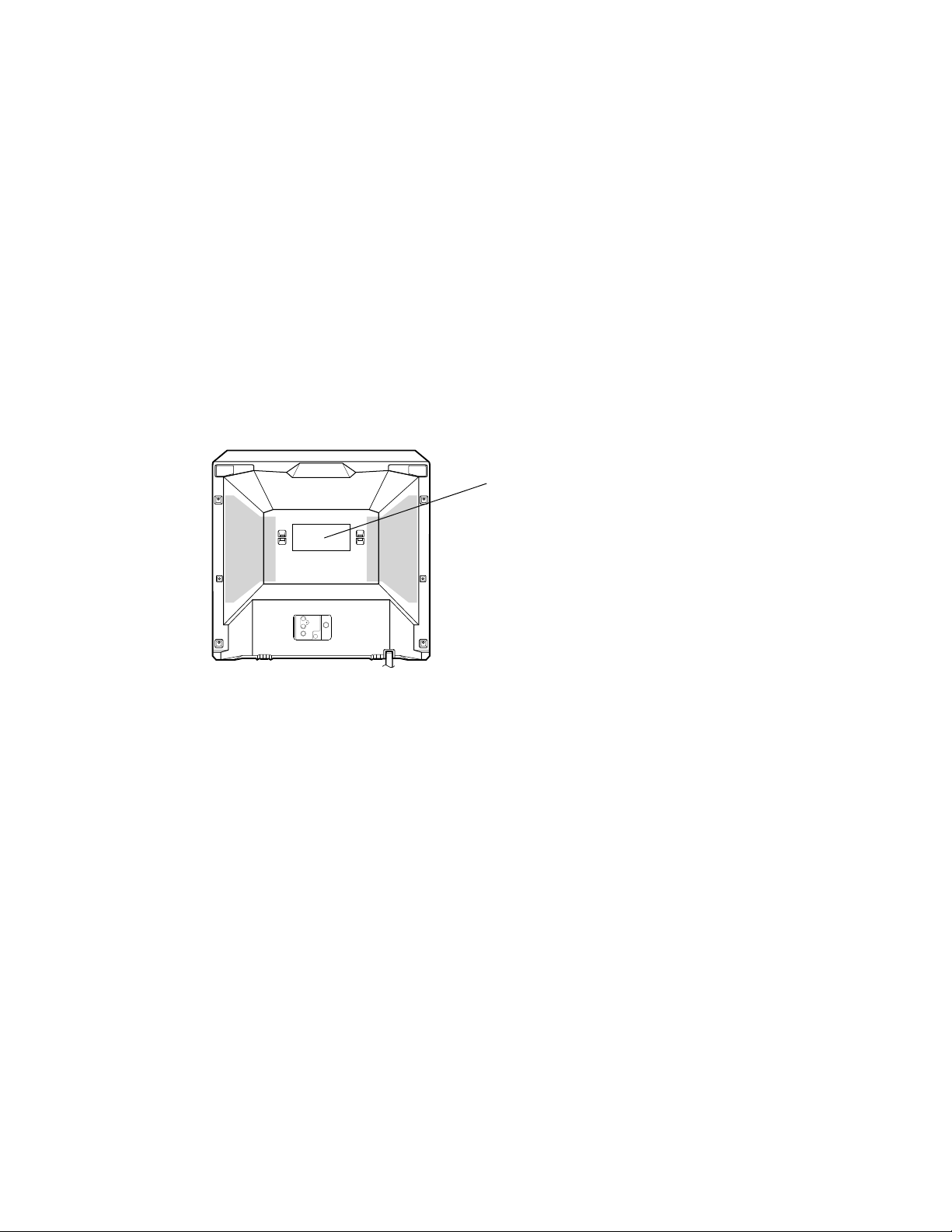
Location of the required Marking
The rating sheet and the safety caution are on the rear of the unit.
AV-20FD24
CERTIFICATION: COMPLIES WITH FDA
RADIATION PERFORMANCE STANDARDS,
21 CFR SUBCHAPTER J.
R
No. 52133
3
Page 4

AV-20FD24
IMPORTANT!SERVICE!SAFETY!INFORMATION
Operating the receiver outside of its cabinet or with its back
removed involves a shock hazard. Work on these models should
only be performed by those who are thoroughly familiar with
precautions necessary when working on high voltage equipment.
Exercise care when servicing this chassis with power applied. Many
B plus and high voltage RF terminals are exposed which, if carelessly contacted, can cause serious shock or result in damage to the
chassis.
Maintain interconnecting ground lead connections between chassis,
escutcheon, picture tube dag and tuner cluster when operating the
chassis.
These receivers have a "polarized" AC line cord. The AC plug is
designed to fit into standard AC outlets in one direction only. The
wide blade connects to the "ground side" and the narrow blade
connects to the "hot side" of the AC line. This assures that the TV
receiver is properly grounded to the house wiring. If an extension
cord must be used, make sure it is of the "polarized" type.
Since the chassis of this receiver is connected to one side of the AC
supply during operation, service should not be attempted by anyone
not familiar with the precautions necessary when working on these
types of equipment.
When it is necessary to make measurements or tests with AC power
applied to the receiver chassis, an Isolation Transformer must be
used as a safety precaution and to prevent possible damage to
transistors. The Isolation Transformer should be connected between
the TV line cord plug and the AC power outlet.
Certain HV failures can increase X-ray radiation.
Receivers should not be operated with HV levels exceeding the
specified rating for their chassis type. The maximum operating HV
specified for the chassis used in these receivers is 32kV±1.0kV at
zero beam current with a line voltage of 120V AC. Higher voltage
may also increase the possibility of failure in the HV supply.
It is important to maintain specified values of all components in the
horizontal and high voltage circuits and anywhere else in the
receiver that could cause a rise in high voltage, or operating supply
voltages. No changes should be made to the original design of the
receiver.
Components shown in the shaded areas on the schematic diagram
and/or identified by ! in the replacement parts list should be
replaced only with exact factory recommended replacement parts.
The use of unauthorized substitute parts may create shock, fire, Xray radiation, or other hazards.
The picture tube used in this receiver employs integral implosion
protection. Replace with a tube of the same type number for
continued safety. Do not lift picture tube by the neck. Handle the
picture tube only when wearing shatterproof goggles and after
discharging the high voltage completely. Keep others without
shatterproof goggles away.
When removing springs or spring mounted parts from the tuner,
tuner cluster or chassis, shatterproof goggles must be worn. Keep
others without shatterproof goggles away.
Before returning the receiver to the user, perform the following
safety checks:
1. Inspect all lead dress to make certain that leads are not pinched
or that hardware is not lodged between the chassis and other
metal parts in the receiver.
2. Replace all protective devices such as nonmetallic control knobs,
insulating fishpapers, cabinet backs, adjustment and compartment covers or shields, isolation resistor-capacitor networks,
mechanical insulators, etc.
3. To be sure that no shock hazard exists, a check for the presence
of leakage current should be made at each exposed metal part
having a return path to the chassis (antenna, cabinet metal,
screw heads, knobs and/or shafts, escutcheon, etc.) in the
following manner.
Plug the AC line cord directly into a 120V AC receptacle.
(Do not use an Isolation Transformer during these checks.) All
checks must be repeated with the AC line cord plug connection
reversed. (If necessary, a nonpolarized adapter plug must be used
only for the purpose of completing these checks.)
If available, measure current using an accurate leakage current
tester. Any reading of 0.35mA or more is excessive and indicates a
potential shock hazard which must be corrected before returning the
receiver to the owner.
If a reliable leakage current tester is not available, this alternate
method of measurement should be used.
Using two clip leads, connect a 1500 ohm, 10 watt resistor paralleled by a 0.15µF capacitor in series with a known earth ground,
such as a water pipe or conduit and the metal part to be checked.
Use a VTVM or VOM with 1000 ohms per volt, or higher, sensitivity
to measure this AC voltage drop across the resistor. Any reading of
0.35 volt RMS or more is excessive and indicates a potential shock
hazard which must be corrected before returning the receiver to the
owner.
To determine the presence of high voltage, use an accurate high
impedance HV meter connected between the second anode lead
and the CRT dag grounding device. When servicing the High
Voltage System, remove static charges from it by connecting a 10k
ohm resistor in series with an insulated wire (such as a test probe)
between the picture tube dag and 2nd anode lead (have AC line
cord disconnected from AC supply).
4
No. 52133
TO EXPOSED
METAL PARTS
VT VM
AC SCALE
1.5K OHMS
10W
15µF
TEST PROBE
TO KNOWN
EARTH GROUND
Page 5

AV-20FD24
IMPORTANT!SAFEGUARDS
1. READ!INSTRUCTIONS
All the safety and operating instructions should be read before the unit is operated.
2. RETAIN!INSTRUCTIONS
The safety and operating instructions should be retained for future reference.
3. HEED!WARNINGS
All warnings on the unit and in the operating instructions should be adhered to.
4. FOLLOW!INSTRUCTIONS
All operating and use instructions should be followed.
5. CLEANING
Unplug this unit from the wall outlet before cleaning. Do not use liquid cleaners or aerosol cleaners. Use a damp cloth for cleaning.
6. ATTACHMENTS
Do not use attachments not recommended by the unit’s manufacturer as they may cause hazards.
7. WATER!AND!MOISTURE
Do not use this unit near water. For example, near a bathtub, washbowl, kitchen sink, or laundry tub, in a wet basement, or near a swimming
pool.
8 ACCESSORIES
Do not place this unit on an unstable cart, stand, tripod, bracket, or table. The unit may fall, causing
serious injury, and serious damage to the unit. Use only with a cart, stand, tripod, bracket, or table
recommended by the manufacturer.
8A. An appliance and cart combination should be moved with care. Quick stops, excessive force, and
uneven surfaces may cause the appliance and cart combination to overturn.
9. VENTILATION
Slots and openings in the cabinet and in the back or bottom are provided for ventilation, to ensure reliable operation of the unit, and to
protect it from overheating. These openings must not be blocked or covered. The openings should never be blocked by placing the unit on a
bed, sofa, rug, or other similar surface. This unit should never be placed near or over a radiator or heat source. This unit should not be
placed in a built-in installation such as a bookcase or rack unless proper ventilation is provided or the manufacturer’s instructions have been
adhered to.
10. POWER!SOURCES
This unit should be operated only from the type of power source indicated on the rating plate. If you are not sure of the type of power supply
to your home, consult your appliance dealer or local power company. For units intended to operate from battery power, or other sources,
refer to the operating instructions.
11. GROUNDING!OR!POLARIZATION
This unit is equipped with a polarized alternating-current line plug (a plug having one blade wider than the other). This plug will fit into the
power outlet only one way. This is a safety feature. If you are unable to insert the plug fully into the outlet, try reversing the plug. If the plug
should still fail to fit, contact your electrician to replace your obsolete outlet. Do not defeat the safety purpose of the polarized plug. If your
unit is equipped with a 3-wire grounding-type plug, a plug having a third (grounding) pin, this plug will only fit into a grounding-type power
outlet. This too, is a safety feature. If you are unable to insert the plug into the outlet, contact your electrician to replace your obsolete outlet.
Do not defeat the safety purpose of the grounding-type plug.
12. POWER-CORD!PROTECTION
Power-supply cords should be routed so that they are not likely to be walked on or pinched by items placed upon or against them, paying
particular attention to cords at plugs, convenience receptacles, and the point where they exit from the appliance.
13. LIGHTNING
To protect your unit from a lightning storm, or when it is left unattended and unused for long periods of time, unplug it from the wall outlet and
disconnect the antenna or cable system. This will prevent damage to the unit due to lightning and power line surges.
14. POWER!LINES
An outside antenna system should not be located in the vicinity of overhead power lines or other electric light or power circuits, or where it
can fall into such power lines or circuits. When installing an outside antenna system, extreme care should be taken to keep from touching
such power lines or circuits, as contact with them might be fatal.
15. OVERLOADING
Do not overload wall outlets and extension cords, as this can result in a risk of fire or electric shock.
16. OBJECT!AND!LIQUID!ENTRY
Do not push objects through any openings in this unit, as they may touch dangerous voltage points or short out parts that could result in fire
or electric shock. Never spill or spray any type of liquid into the unit.
17. OUTDOOR!ANTENNA!GROUNDING
If an outside antenna or cable system is connected to the unit, be sure the antenna or cable system is grounded so as to provide some
protection against voltage surges and built-up static charges. Section 810 of the National Electrical Code, ANSI/NFPA 70, provides information with respect to proper grounding of the mast and supporting structure, grounding of the lead-in wire to an antenna discharge unit, size of
grounding conductors, location of antenna discharge unit, connection to grounding electrodes, and requirements for the grounding electrode.
18. SERVICING
Do not attempt to service this unit yourself as opening or removing covers may expose you to dangerous voltage or other hazards.
Refer all servicing to qualified service personnel.
PORTABLE CART WARNING
(symbol provided by RETAC)
S3126A
No. 52133
5
Page 6
AV-20FD24
19. DAMAGE!REQUIRING!SERVICE
Unplug this unit from the wall outlet and refer servicing to qualified service personnel under the following conditions:
a. When the power-supply cord or plug is damaged.
b. If liquid has been spilled, or objects have fallen into the unit.
c. If the unit has been exposed to rain or water.
d. If the unit does not operate normally by following the operating instructions. Adjust only those controls that are covered by the
operating instructions, as an improper adjustment of other controls may result in damage and will often require extensive work by a
qualified technician to restore the unit to its normal operation.
e. If the unit has been dropped or the cabinet has been damaged.
f. When the unit exhibits a distinct change in performance, this indicates a need for service.
20. REPLACEMENT!PARTS
When replacement parts are required, be sure the service technician uses replacement parts specified by the manufacturer or those that
have the same characteristics as the original parts.
Unauthorized substitutions may result in fire, electric shock or other hazards.
21. SAFETY!CHECK
Upon completion of any service or repairs to this unit, ask the service technician to perform safety checks to determine that the unit is in
proper operating condition.
22. WALL!OR!CEILING!MOUNTING
The product should be mounted to a wall or ceiling only as recommended by the manufacturer.
23. HEAT
The product should be situated away from heat sources such as radiators, heat registers, stoves, or other products (including amplifiers) that
produce heat.
24. DISC!TRAY
Keep your fingers well clear of the disc tray as it is closing. It may cause serious personal injury.
25. CONNECTING
When you connect the product to other equipment, turn off the power and unplug all of the equipment from the wall outlet. Failure to do so
may cause an electric shock and serious personal injury. Read the owner's manual of the other equipment carefully and follow the instructions when making any connections.
26. SOUND!VOLUME
Reduce the volume to the minimum level before you turn on the product. Otherwise, sudden high volume sound may cause hearing or
speaker damage.
27. SOUND!DISTORTION
Do not allow the product output distorted sound for a longtime. It may cause speaker overheating and fire.
28. HEADPHONES
When you use the headphones, keep the volume at a moderate level. If you use the headphones continuously with high volume sound, it
may cause hearing damage.
29. LEASER!BEAM
Do not look into the opening of the disc tray or ventilation opening of the product to see the source of the laser beam. It may cause sight
damage.
30. DISC
Do not use a cracked, deformed, or repaired disc. These discs are easily broken and may cause serious personal injury and product
malfunction.
31. NOTE!TO!CATV!SYSTEM!INSTALLER
This reminder is provided to call the CATV system installer’s attention to Article 820-40 of the NEC that provides guidelines for proper
grounding and, in particular, specifies that the cable ground shall be connected to the grounding system of the building, as close to the point
of cable entry as practical.
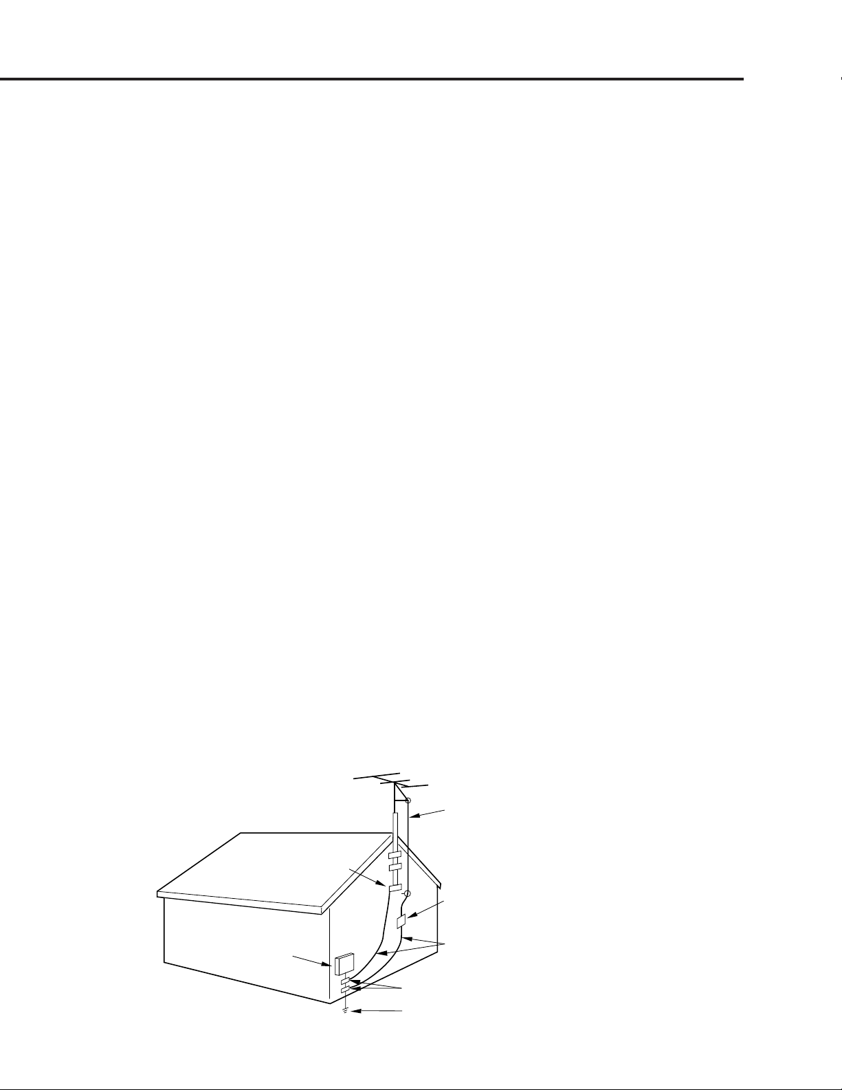
EXAMPLE OF ANTENNA GROUNDING AS PER THE NATIONAL ELECTRICAL CODE
ELECTRIC SERVICE
EQUIPMENT
NEC-NATIONAL ELECTRICAL CODE
S2898A
6
ANTENNA LEAD IN WIRE
GROUND CLAMP
ANTENNA DISCHARGE UNIT
(NEC SECTION 810-20)
GROUNDING CONDUCTORS
(NEC SECTION 810-21)
GROUND CLAMPS
POWER SERVICE GROUNDING ELECTRODE SYSTEM
(NEC ART 250, PART H)
No. 52133
Page 7
SPECIFIC!SERVICE!INSTRUCTIONS
DISASSEMBLY!INSTRUCTIONS
AV-20FD24
1. REMOVAL!OF!MECHANICAL!PARTS
AND!P.C.!BOARDS
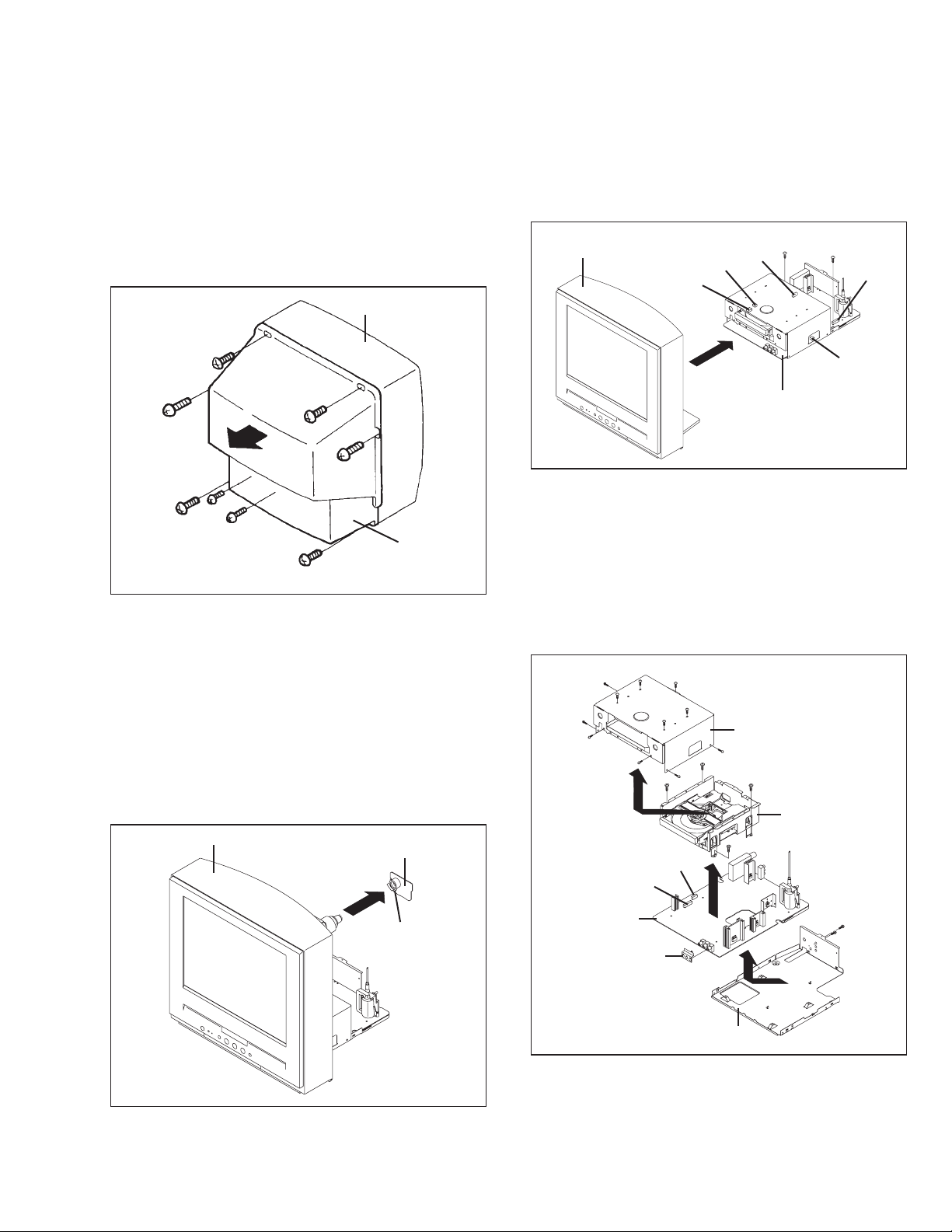
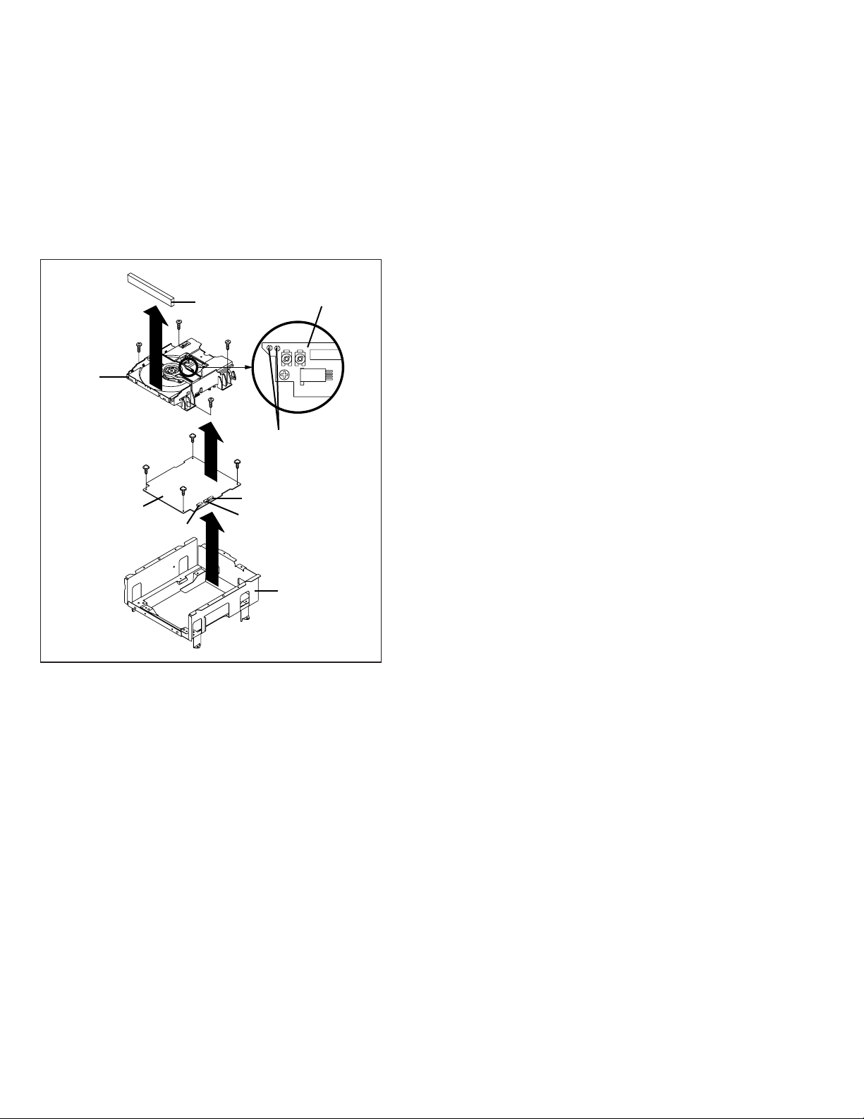
1-1:!BACK!CABINET!(Refer!to!Fig.!1-1)
1. Remove the 7 screws 1.
2. Remove the screw 2 which are used for holding the Back
Cabinet.
3. Remove the AC cord from the AC cord hook 3.
4. Remove the Back Cabinet in the direction of arrow.
Front Cabinet
1
1
1
1
2
1-2:!CRT!PCB!(Refer!to!Fig.!1-2)
CAUTION: BEFORE!REMOVING!THE!ANODE!CAP,!DISCHARGE
ELECTRICITY!BECAUSE!IT!CONTAINS!HIGH
VOLTAGE.
BEFORE!ATTEMPTING!TO!REMOVE!OR!REPAIR
ANY!PCB,!UNPLUG!THE!POWER!CORD!FROM!THE
AC!SOURCE.
1. Remove the Anode Cap.
(Refer to REMOVAL OF ANODE CAP)
2. Disconnect the following connector:
(CP801).
3. Remove the CRT PCB in the direction of arrow.
Front Cabinet
1
1
3
Back Cabinet
1
Fig. 1-1
CRT PCB
CP805
1-3:!AV!PCB/DVD!BLOCK!(Refer!to!Fig.!1-3)
1. Remove the 2 screws 1.
2. Disconnect the following connectors:
(CP104, CP301, CP302, CP401 and CP3800).
3. Remove the AV PCB/DVD Block in the direction of arrow.
Front Cabinet
CP104
CP3800
CP301
AV PCB/DVD Block
1
1
CP302
1-4:!DVD!BLOCK!(Refer!to!Fig.!1-4)
1. Remove the 11 screws 1.
2. Remove the Top Shield in the direction of arrow (A).
3. Disconnect the following connectors:
(CP8001 and CP8002).
4. Remove the 4 screws 2.
5. Remove the DVD Block in the direction of arrow (B).
6. Remove the 2 screws 3.
7. Remove the Jack Shield.
8. Remove the AV PCB in the direction of arrow (C).
1
1
1
1
1
(A)
AV PCB
Jack Shield
1
2
CP8001
1
1
1
CP8002
Top Shield
1
2
1
2
DVD Block
2
(B)
3
3
(C)
CP401
Fig. 1-3
Fig. 1-2
No. 52133
Plate Bottom
Fig. 1-4
7
Page 8
AV-20FD24
1-5:!DVD!PCB/DVD!DECK!(Refer!to!Fig.!1-5)
1. Make the short circuit on the position as shown Fig.!1-5 using a
soldering. If you remove the DVD Deck with no soldering, the
Laser may be damaged.
2. Unlock the 2 supports 1.
3. Remove the Front Tray Plate in the direction of arrow (A).
4. Disconnect the following connectors:
(CP2001, CP2301 and CP2302).
5. Remove the 4 screws 2.
6. Remove the DVD Deck in the direction of arrow (B).
7. Remove the 4 screws 3.
8. Remove the DVD PCB in the direction of arrow (C).
Deck CD
1
(A)
2
3
DVD PCB
1
3
CP2301
Front Tray Plate
2
2
(B)
3
(C)
2
Make the sort circuit
using a soldering.
3
CP2001
CP2302
Pick Up PCB
Deck Angle
Fig. 1-5
NOTE
When the installation of the DVD Deck, remove all the soldering on
the short circuit position after the connection of Pick Up PCB and
DVD PCB connector.
8
No. 52133
Page 9
AV-20FD24
2
2. REMOVAL!OF!DVD!DECK!PARTS
NOTE
1. Do not disassemble the DVD DECK PARTS except listedparts
here. Minute adjustments are needed if the disassemble is done.
If the repair is needed except listed parts, replace the DVD
MECHA ASS’Y.
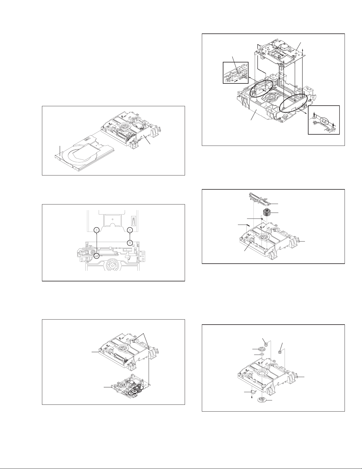
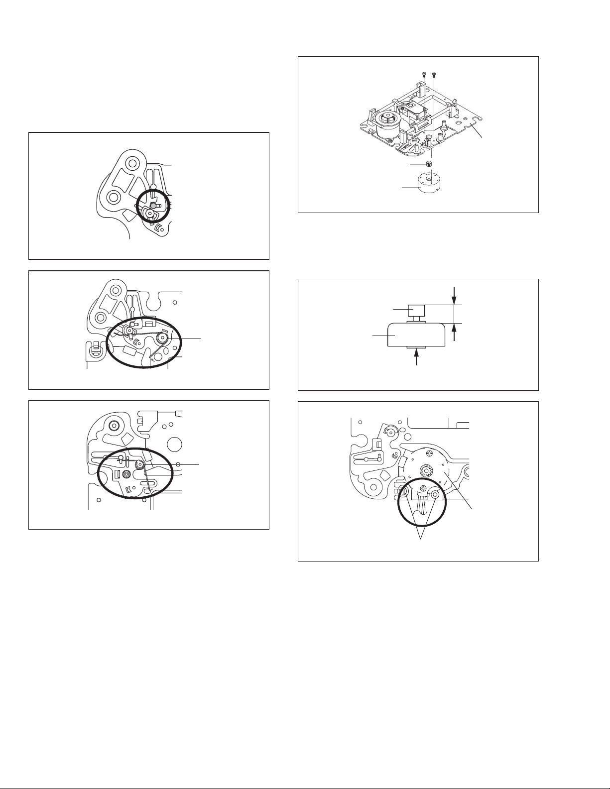
2-1:!TRAY!(Refer!to!Fig.!2-1-A)
1. Set the Tray opened. (Refer!to!the!DISC!REMOVAL!METHOD
AT!NO!POWER!SUPPLY)
2. Unlock the support 1 and remove the Tray.
1
Tray
NOTE
1. In case of the Tray installation, install them as the circled section
of Fig. 2-1-B so that the each markers are met.
Tray
Main Frame Ass’y
Fig. 2-1-A
Main Chassis Ass’y
Rack Loading
Move it to the direction
of the arrow.
1
Main Frame Ass’y
2
3
5
6
4
6
Check Lock
4
5
Fig. 2-2-B
2-3: RACK!LOADING/MAIN!GEAR/!RACK!LOADING!SPRING
(Refer!to!Fig.!2-3)
1. Remove the Rack L Spring.
2. Press down the catcher 1 and slide the Rack Loading.
3. Remove the Rack Loading, Rack Loading Spring and Main Gear.
Rack Loading
Rack Loading Spring
Rack L Spring
Main Gear
Main Frame
Ass’y
Fig. 2-1-B
2-2:!MAIN!CHASSIS!ASS’Y!(Refer!to!Fig.!2-2-A)
1. Remove the Main Chassis Ass’y from the Insulator (R).
2. Unlock the support 1.
3. Remove the Main Chassis Ass’y.
Insulator (R)
(Green)
Main Frame Ass’y
Main Chassis
Ass’y
1
Fig. 2-2-A
NOTE
1. In case of the Main Chassis Ass’y, install it from (1) to (6) in
order. (Refer!to!Fig.!3-2-B)
Main Frame Ass’y
1
Fig. 2-3
2-4:!CLAMPER!ASS’Y/INSULATOR(R)/LEVER!SWITCH
(Refer!to!Fig.!2-4-A)
1. Remove the screw 1.
2. Remove the Lever Switch.
3. Remove the 2 Insulator (R).
4. Press the Clamper and rotate the Clamper Plate clockwise, then
unlock the 3 supports 2.
5. Remove the Clamper Plate, Clamper Magnet and Clamper.
Insulator (R)
Clamper Plate
Clamper Magnet
Lever Switch
(Green)
2
1
2
Insulator (R)
(Green)
Clamper
Main Frame
Fig. 2-4-A
No. 52133
9
Page 10
AV-20FD24
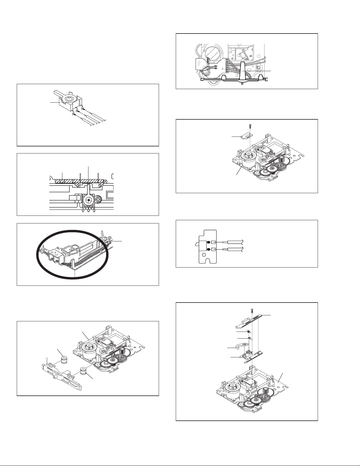
NOTE
1. When installing the Clamper Magnet, install it with the green face
up.
2. When installing the wire of the Lever Switch, install it correctly as
Fig. 2-4-B.
3. When installing the Lever Switch, install it correctly as Fig. 2-4-C.
4. In case of the Lever Switch installation, hook the wire on the
Main Frame as shown Fig. 2-4-D.
Lever Switch
Red
White
Blue
From DVD PCB
Fig. 2-4-B
The Lever should be position
The Lever should be position
between A and B.
between A and B.
Rack Loading
Rack Loading
A
A
B
B
Fig. 2-4-C
Main Chassis Ass’y
T
raverse Holder
Fig. 2-5-B
2-6:!SWITCH!PCB!ASS’Y!(Refer!to!Fig.!2-6-A)
1. Remove the screw 1.
2. Remove the Switch PCB Ass’y.
1
Switch PCB Ass’y
Main Chassis Ass’y
• Screw Torque: 4 ±
0.5kgf•cm
Fig. 2-6-A
NOTE
1. When installing the wire of the Switch PCB, install it correctly as
Fig. 2-6-B.
2-5:!TRAVERSE!HOLDER/INSULATOR!(F)
(Refer!to!Fig.!2-5-A)
1. Remove the Traverse Holder.
2. Remove the 2 Insulator (F).
Main Chassis Ass’y
Insulator (F)
(Black)
Traverse Holder
Insulator (F)
(Black)
Lever Switch
Fig. 2-4-D
Fig. 2-5-A
Switch PCB Ass’y
Black
From Relay PCB
White
Fig. 2-6-B
2-7:!RACK!FEED!ASS’Y!(Refer!to!Fig.!2-7-A)
1. Remove the screw 1.
2. Remove the Rack Feed 1/2 Spring, Rack Feed 1/2 and Rack
Feed Lever.
1
Rack Feed 2
Rack Feed 1 Spring
Rack Feed 2 Spring
Rack Feed Lever
Rack Feed 1
Main Chassis
Ass’y
NOTE
1. After the installing of the Traverse Holder, check if the wire is like
Fig. 2-5-B.
10
No. 52133
• Screw Torque: 3.5 ± 0.5kgf•cm
Fig. 2-7-A
Page 11
AV-20FD24
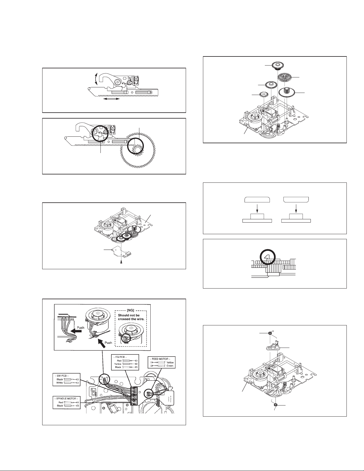
NOTE
1. After the assembly of the Rack Feed, check if the Rack Feed 1/2
is moving smoothly.!(Refer!to!Fig.!2-7-B)
2. In case of the Rack Feed AssÅfy installation, install correctly as
Fig. 2-7-C.
Moving smoothly
Moving smoothly
Check the position of
the Rack Feed Lever
Should not be engaged.
.
Fig. 2-7-B
Fig. 2-7-C
2-8:!RELAY!PCB!ASS’Y!(Refer!to!Fig.!2-8-A)
1. Remove the screw 1.
2. Remove the Relay PCB Ass’y.
2-9:!GEAR!(Refer!to!Fig.!2-9-A)
1. Unlock the support 1.
2. Remove the Middle Gear 1/2/3, Idler Gear and Feed Gear.
Middle Gear 2
Middle Gear 1
Middle Gear 3
Idler Gear
Main Chassis
Ass’y
Feed Gear
Fig. 2-9-A
NOTE
1. In case of the Idler Gear installation, install correctly as Fig. 2-9B.
2. When installing the Middle Gear 2, check if the Middle Gear 2 is
locked correctly as Fig. 2-9-C.
[OK]
Idler Gear
[NG]
Idler Gear
Main Chassis Ass’y
Relay PCB Ass’y
• Screw Torque: 4 ± 0.5kgf•cm
1
Fig. 2-8-A
NOTE
1. When installing the wire of the Relay PCB, install it correctly as
Fig. 2-8-B.
Idler Arm
Check Lock
Middle Gear 2
2-10:!IDLER!ARM!(Refer!to!Fig.!2-10-A)
1. Remove the Idler Arm Spring.
2. Remove the Chassis Spring.
3. Remove the Idler Arm.
Idler Arm Spring
Idler Arm
Idler Arm
Fig. 2-9-B
Fig. 2-9-C
Fig. 2-8-B
No. 52133
Main Chassis Ass’y
Chassis Spring
Fig. 2-10-A
11
Page 12
AV-20FD24
NOTE
1. In case of the Idler Arm installation, install as the circled section
of Fig. 2-10-B.
2. In case of the Idler Arm Spring installation, install as the circled
section of Fig. 2-10-C.
3. In case of the Chassis Spring installation, install as the circled
section of Fig. 2-10-D.
Idler Arm
Main Chassis Ass’y
Fig. 2-10-B
Idler Arm Spring
11
Main Chassis Ass’y
Motor Gear
Feed Motor
• Screw Torque: 1 ± 0.5kgf•cm
Fig. 2-11-A
NOTE
1. In case of the Motor Gear installation, check if the valueof the
Fig. 2-11-B is correct.
2. When installing the Feed Motor, check if the cable is positioned
as Fig. 2-11-C.
Motor Gear
Feed Motor
6.1 ± 0.1mm
Main Chassis Ass’y
Main Chassis
Ass’y
2-11:!FEED!MOTOR!(Refer!to!Fig.!2-11-A)
1. Remove the 2 screws 1.
2. Remove the Feed Motor.
3. Remove the Motor Gear.
Fig. 2-10-C
Chassis Spring
Fig. 2-10-D
Safety surface for pressing
of the insert.
Main Chassis Ass’y
Pass the cable
between 2 pins.
Fig. 2-11-B
Feed Motor
Fig. 2-11-C
12
No. 52133
Page 13
AV-20FD24
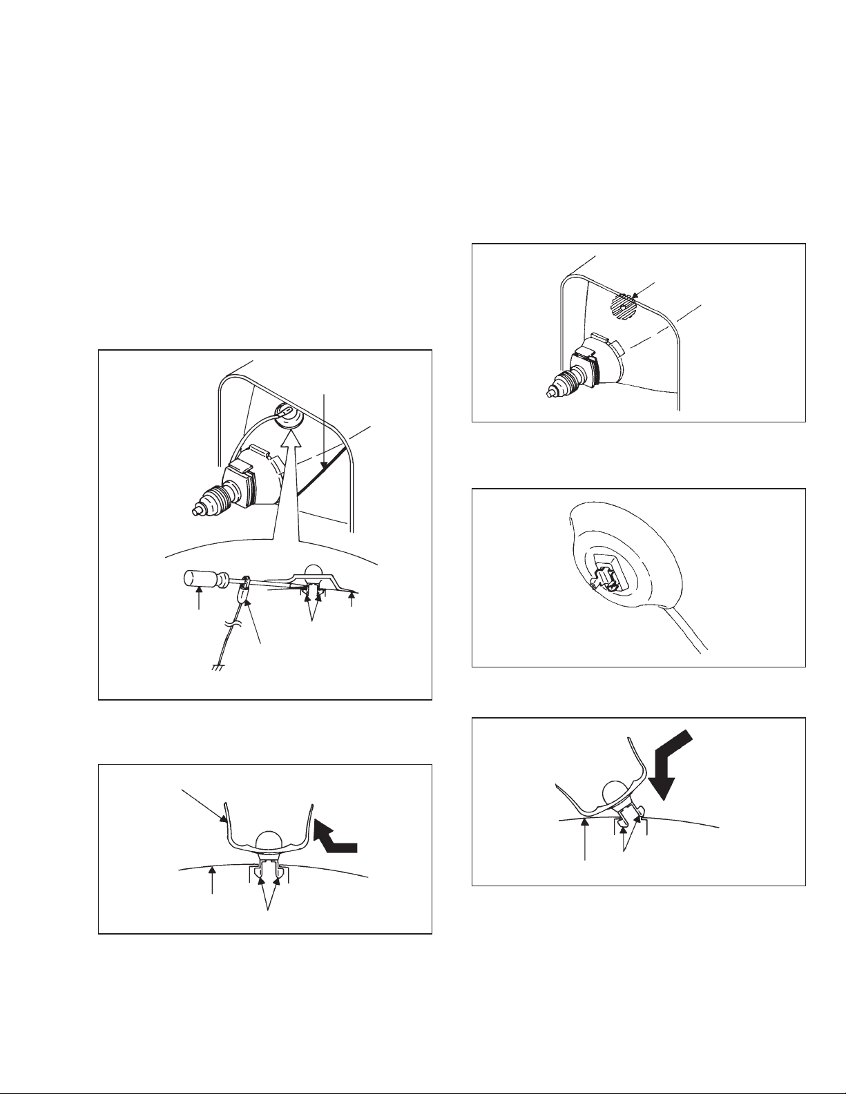
3.!REMOVAL!OF!ANODE!CAP
Read the following NOTED items before starting work.
•After turning the power off there might still be a potential voltage
that is very dangerous. When removing the
Anode Cap, make sure to discharge the Anode Cap's potential
voltage.
•Do not use pliers to loosen or tighten the Anode Cap terminal,
this may cause the spring to be damaged.
REMOVAL
1. Follow the steps as follows to discharge the Anode Cap.
(Refer!to!Fig.!3-1.)
Connect one end of an Alligator Clip to the metal part of a flatblade screwdriver and the other end to ground.
While holding the plastic part of the insulated Screwdriver, touch
the support of the Anode with the tip of the Screwdriver.
A cracking noise will be heard as the voltage is discharged.
GND on the CRT
3. After one side is removed, pull in the opposite direction to
remove the other.
NOTE
Take care not to damage the Rubber Cap.
INSTALLATION
1. Clean the spot where the cap was located with a small amount of
alcohol. (Refer!to!Fig.!3-3.)
NOTE
Confirm that there is no dirt, dust, etc. at the spot where the cap
was located.
Location of Anode Cap
Fig. 3-3
2. Arrange the wire of the Anode Cap and make sure the wire is not
twisted.
3. Turn over the Rubber Cap.!(Refer!to!Fig.!3-4.)
Screwdriver
Support
CRT
Alligator Clip
GND on the CRT
2. Flip up the sides of the Rubber Cap in the direction of the arrow
and remove one side of the support.
(Refer!to!Fig.!3-2.)
Fig. 3-1
Rubber Cap
CRT
Support
Fig. 3-2
Fig. 3-4
4. Insert one end of the Anode Support into the anode button, then
the other as shown in Fig.!3-5.
Support
CRT
5. Confirm that the Support is securely connected.
6. Put on the Rubber Cap without moving any parts.
Fig. 3-5
No. 52133
13
Page 14

AV-20FD24
4.
REMOVAL!AND!INSTALLATION!OF!FLAT
PACKAGE!IC
REMOVAL
1. Put the Masking Tape (cotton tape) around the Flat Package IC
to protect other parts from any damage.
(Refer!to!Fig.!4-1.)
NOTE
Masking is carried out on all the parts located within 10 mm
distance from IC leads.
IC
Masking Tape
(Cotton Tape)
Fig. 4-1
2. Heat the IC leads using a blower type IC desoldering machine.
(Refer!to!Fig.!4-2.)
NOTE
Do not add the rotating and the back and forth directions force
on the IC, until IC can move back and fortheasily after
desoldering the IC leads completely.
Blower type IC
desoldering machine
3. When IC starts moving back and forth easily after desoldering
completely, pickup the corner of the IC usinga tweezers and
remove the IC by moving with the IC desoldering machine.
(Refer!to!Fig.!4-3.)
NOTE
Some ICs on the PCB are affixed with glue, so be careful not
to break or damage the foil of each IC leads or solder lands
under the IC when removing it.
Blower type IC
desoldering machine
Tweezers
IC
Fig. 4-3
4. Peel off the Masking Tape.
5. Absorb the solder left on the pattern using the Braided Shield
Wire. (Refer!to!Fig.!4-4.)
NOTE
Do not move the Braided Shield Wire in the vertical direction
towards the IC pattern.
14
Braided Shield Wire
Soldering Iron
IC
Fig. 4-2
IC pattern
Fig. 4-4
No. 52133
Page 15

AV-20FD24
INSTALLATION
1. Take care of the polarity of new IC and then install the new IC
fitting on the printed circuit pattern. Then solder each lead on the
diagonal positions of IC temporarily.
(Refer!to!Fig.!4-5.)
Soldering Iron
Solder temporarily
Solder temporarily
Fig. 4-5
2. Supply the solder from the upper position of IC leads sliding to
the lower position of the IC leads.
(Refer!to!Fig.!4-6.)
4. When bridge-soldering between terminals and/or the soldering
amount are not enough, resolder using a Thintip Soldering Iron.
(Refer!to!Fig.!4-8.)
IC
Thin-tip Soldering Iron
Fig. 4-8
5. Finally, confirm the soldering status on four sides of the IC using
a magnifying glass.
Confirm that no abnormality is found on the soldering position
and installation position of the parts around the IC. If some
abnormality is found, correct by resoldering.
NOTE
When the IC leads are bent during soldering and/or repairing,
do not repair the bending of leads. If thebending of leads are
repaired, the pattern may be damaged. So, be always sure to
replace the IC in this case.
Solder
IC
Supply soldering
from upper position
to lower position
Soldering Iron
Fig. 4-6
3. Absorb the solder left on the lead using the Braided Shield Wire.
(Refer!to!Fig.!4-7.)
NOTE
Do not absorb the solder to excess.
Soldering Iron
IC
Braided Shield Wire
Fig. 4-7
No. 52133
15
Page 16

AV-20FD24
SERVICE!MODE!LIST
This unit provided with the following SERVICE MODES so you can repair, examine and adjust easily.
To enter to the SERVICE MODE function, press and hold both buttons simultaneously on the main unit and on the remote control for more than a
standard time (second).
Set!Key Remocon!Key Operations
VOL. (-) MIN
VOL. (-) MIN
VOL. (-) MIN
VOL. (-) MIN
VOL. (-) MIN
0
1
4
5
6
Standard!Time
(seconds)
1
1
1
1
1
Releasing of V-CHIP PASSWORD.
Initialization of the factory on TV.
NOTE: Do not use this for the normal servicing.
If you set a factory initialization, the memories are reset such as the
channel setting, and the POWER ON total hours.
Initialization of the factory on DVD.
NOTE: Do not use this for the normal servicing.
The function will only work without the setting of DVD disc at DVD
mode.
While pressing the Remocon Key for more than the Standard Time,
press the Set Key simultaneously.
DVD Write mode.
Refer to the “RE-WRITE FOR DVD FIRMWARE”.
NOTE: The function will only work at the DVD stop mode.
Do not use this for the normal servicing.
POWER ON total hours is displayed on the screen.
Refer to the "PREVENTIVE CHECKS AND SERVICE INTERVALS"
(CONFIRMATION OF HOURS USED).
VOL. (-) MIN
VOL. (-) MIN
STOP
STOP
Can be checked of the INITIAL DATA of MEMORY IC.
Refer to the "WHEN REPLACING EEPROM (MEMORY) IC".
8
9
1
7
1
1
3
3
Writing of EEPROM initial data.
NOTE: Do not use this for the normal servicing.
Display of the Adjustment MENU on the screen.
Refer to the "ELECTRICAL ADJUSTMENT" (On-Screen Display Adjustment).
Check for the firmware version.
Refer to the “RE-WRITE FOR DVD FIRMWARE”.
NOTE: The function will only work at the DVD stop mode.
Do not use this for the normal servicing.
Releasing of PARENTAL LOCK.
Refer to the “PARENTAL CONTROL - RATING LEVEL”.
NOTE: The function will only work without the setting of DVD disc at DVD
mode.
16
No. 52133
Page 17

PARENTAL!CONTROL!-!RATING!LEVEL
(
)
4!DIGIT!PASSWORD!CANCELLATION
If the stored 4 digit password in the Rating Level menu needs to be cancelled, please follow the steps below.
1. Turn Unit ON and set the DVD mode.
2. Check that the “No disk” is displayed on the screen.
3. Press and hold the ‘STOP’ button on the front panel.
4. Simultaneously press and hold the ‘7’ key on the remote control unit.
5. Hold both keys for more than 3 second.
6. The On Screen Display message ‘PASSWORD CLEAR’ will appear.
7. The 4 digit password has now been cleared.
CONFIRMATION!OF!HOURS!USED
POWER ON total hours can be checked on the screen. Total hours are displayed in 16 system of notation.
NOTE:!If!you!set!a!factory!initialization,!the!total!hours!is!reset!to!"0".
1. Set the VOLUME to minimum.
2. Press both VOL. DOWN button on the set and Channel button (6)
on the remote control for more than 1 second.
3. After the confirmation of using hours, turn off the power.
ADDRESS DATA
INIT 00 06
CRT ON 0010
FIG. 1
Initial setting content of MEMORY IC.
POWER ON total hours.
= (16 x 16 x 16 x thousands digit value)
+ (16 x 16 x hundreds digit value)
+ (16 x tens digit value)
ones digit value
+
AV-20FD24
WHEN!REPLACING!EEPROM!(MEMORY)!IC
If a service repair is undertaken where it has been required to change the MEMORY IC, the following steps should be taken to ensure correct
data settings while making reference to TABLE 1.
NOTE:!No!need!setting!for!after!INI!1F!due!to!the!adjustment!value.
INI
+0 +1 +2 +3 +4 +5 +6 +7 +8 +9 +A +B +C +D +E +F
06 3F 4C 00 D1 05 30 25 15 53
00 01 00 55 40 0F 77
30 50 AA 49 78 03 50 50 7810 50 55 BA 00 00 00 00
Table!1
1. Enter DATA SET mode by setting VOLUME to minimum.
2. Press both VOL. DOWN button on the set and Channel button (6) on the remote control for more than 1 second.
ADDRESS and DATA should appear as FIG 1.
3. ADDRESS is now selected and should "blink". Using the VOL. UP/DOWN button on the remote, step through the ADDRESS until required
ADDRESS to be changed is reached.
4. Press ENTER to select DATA. When DATA is selected, it will "blink".
5. Again, step through the DATA using VOL. UP/DOWN button until required DATA value has been selected.
6. Pressing ENTER will take you back to ADDRESS for further selection if necessary.
7. Repeat steps 3 to 6 until all data has been checked.
8. When satisfied correct DATA has been entered, turn POWER off (return to STANDBY MODE) to finish DATA input.
The unit will now have the correct DATA for the new MEMORY IC.
No. 52133
17
Page 18

AV-20FD24
r
SERVICING!FIXTURES!AND!TOOLS
X-JG176 Up-Date Disc
RE-WRITE!FOR!DVD!FIRMWARE
1. Turn on the power, and set the DVD mode.
2. Confirm that the “No Disc” will be appeared on the screen.
3. Open the DVD tray.
4. Press both VOL. DOWN button on the set and Channel button (5) on the remote control for more than 1 second.
5. Press OPEN/CLOSE button on the unit to check if all the keys on the unit do not function.
NOTE:!To!check!if!DVD!Write!mode!is!set.
6. Place the Up-Date Disc and close the tray by hand.!(Refer!to!SERVICING!FIXTURE!AND!TOOLS)
7. Automatic read will start and "CD-R UPDATE PROCESS" will be displayed on the screen.
8. Approxi. 20 seconds later, the tray will open automatically. Remove the Up-Date Disc.
9. Then, Approxi. 40 seconds later, the above indication will disappear and the tray will close automatically.
10. Unplug the AC cord, then plug it in.
11. After!the!write,!set!to!the!initializing!of!shipping.
12. The "INITIALIZE 9 ---> COMPLETE" will appear on the screen.
13. CHECK!FOR!THE!FIRMWARE!VERSION
14. Turn off the power.
When!inserting!Up-Date!Disc!at!Non!DVD!Write!mode,!the!read!error!will!happen.
At this time, the horizontal noise lines may appear. But no problem.
When the "No Disc" appears on the screen, the write will end.
NOTE:!Do!not!turn!off!the!unit!on!the!way!or!push!the!tray!by!hand!to!close!it.
Up-Date!error!will!happen!and!can!not!be!done!with!the!Up-Date!of!Up-Date!Disc.
Set to the DVD mode, press both VOL. DOWN button on the set and Channel button (4) on the remote control for more than 1 second.
Then unplug the AC cord, and plug it in.
Set to the DVD mode, press both Channel button!(1) on the remote control and the STOP button on the set for more than 3 seconds.
Firmware version will be displayed on the top left of the screen.
When the changed version displays, the Re-write will be completed.
Version OSD : UAB35091
U A B 3 5 0 9 1
DISC!REMOVAL!METHOD!AT!NO!POWER!SUPPLY
1. Remove the Back Cabinet and AV PCB/DVD Block.
(Refer!to!item!1!of!the!DISASSEMBLY!INSTRUCTIONS.)
2. Slide the Rack Loading (White) toward the arrow direction by
using a minus driver to release the lock.
(Refer!to!Fig.!1)
3. Draw the Tray.
18
Fixed
No. 52133
Released times on the same date
Release date (Example: 2003.5.9)
A = October
B = November
C = Decembe
Rack Loading
(White)
Deck CD
Page 19

SERVICE!ADJUSTMENTS
ELECTRICAL!ADJUSTMENTS
AV-20FD24
1. BEFORE!MAKING!ELECTRICAL
ADJUSTMENTS
Read and perform these adjustments when repairing the circuits or
replacing electrical parts or PCB assemblies.
CAUTION
•Use an isolation transformer when performing any service on this
chassis.
•Before removing the anode cap, discharge electricity because it
contains high voltage.
•When removing a PCB or related component, after unfastening or
changing a wire, be sure to put the wire back in its original
position.
•When you exchange IC and Transistor for a heat sink, apply the
silicon grease (YG6260M) on the contact section of the heat sink.
Before applying new silicon grease, remove all the old silicon
grease. (Old grease may cause damages to the IC and Transistor).
Prepare!the!following!measurement!tools!for!electrical!adjustments.
1. Oscilloscope
2. Digital Voltmeter
3. AC Voltmeter
4. Pattern Generator
5. Multi-Sound Signal Generator
On-Screen!Display!Adjustment
1. Set the VOLUME to minimum.
2. Press the VOL. DOWN button on the set and the
Channel button (9) on the remote control for more than 1
second to appear the adjustment mode on the screen as shown
in Fig.!1-1.
Function
Step No.
01 OSD
15
NO. FUNCTION NO. FUNCTION
01 OSD H
02 OSD CONTRAST
03 CUT OFF
04 H POSITION
05 H BLK L
06 H BLK R
07 V SIZE
08 V POSITION
09 V LINEARITY
10 V S CORRECTION
11 V COMP
12 R CUT OFF
13 G CUT OFF
14 B CUT OFF
15 R DRIVE
16 G DRIVE
17 B DRIVE
18 BRIGHTNESS(CENT.)
19 BRIGHTNESS(MAX)
20 BRIGHTNESS(MIN)
21 CONTRAST(CENT.)
22 CONTRAST(MAX)
23 CONTRAST(MIN)
24 COLOR(CENT.)
25 COLOR(MAX)
26 COLOR(MIN)
27 TINT
28 SHARPNESS
29 SUB BIAS
30 BRI. AV(CENT.)
31 BRI. AV(MAX)
32 BRI. AV(MIN)
33 CONT. AV(CENT.)
34 CONT. AV(MAX)
35 CONT. AV(MIN)
36 COL. AV(CENT.)
37 COL. AV(MAX)
38 COL. AV(MIN)
39 TINT AV
40 SHARPNESS AV
41 SUB BIAS
42 BRI. DVD(CENT.)
43 BRI. DVD(MAX)
44 BRI. DVD(MIN)
45 CONT. DVD(CENT.)
46 CONT. DVD(MAX)
47 CONT. DVD(MIN)
48 COL. DVD(CENT.)
49 COL. DVD(MAX)
50 COL. DVD(MIN)
51 TINT DVD
52 SHARPNESS DVD
53 SUB BIAS
54 BRI. GAME(CENT.)
55 BRI. GAME(MAX)
56 BRI. GAME(MIN)
57 CONT. GAME(CENT.)
58 CONT. GAME(MAX)
59 CONT. GAME(MIN)
60 SUB BIAS
61 TUNING V MUTE
62 POWER ON V MUTE
63 INPUT LEVEL
64 SEPARATION L
65 SEPARATION H
66 X-RAY TEST
67 H STOP
68 H FREQ
Fig. 1-2
2.!BASIC!ADJUSTMENTS
2-1:!CONSTANT!VOLTAGE
1. Set condition is AV MODE without signal.
2. Using the remote control, set the brightness and contrast to
normal position.
3. Connect the digital voltmeter to TP401.
4. Adjust the VR3800 until the digital voltmeter is 114 ± 0.5V.
Fig. 1-1
3. Use the Channel UP/DOWN button or Channel button (1-0) on
the remote control to select the options shown in Fig.!1-2.
4. Press the MENU button on the remote control to end the
adjustments.
No. 52133
2-2:!FOCUS
1. Receive the monoscope pattern.
2. Turn the Focus Volume fully counterclockwise once.
3. Adjust the Focus!Volume until picture is distinct.
2-3:!CUT!OFF
1. Adjust the unit to the following settings.
R DRIVE=3F, G DRIVE=07, B DRIVE=3F, R CUT OFF=7F, G
CUT OFF=7F, B CUT OFF=7F
2. Place the set with Aging Test for more than 15 minutes.
3. Set condition is AV MODE without signal.
4. Using the remote control, set the brightness and contrast to
normal position.
5. Activate the adjustment mode display of Fig.!1-1 and press the
channel button (03) on the remote control to select "CUT OFF".
6. Adjust the Screen!Volume until a dim raster is obtained.
19
Page 20

AV-20FD24
2-4:!WHITE!BALANCE
NOTE: Adjust after performing CUT OFF adjustment.
1. Place the set with Aging Test for more than 15 minutes.
2. Receive the gray scale pattern from the Pattern Generator.
3. Using the remote control, set the brightness and contrast to
normal position.
4. Activate the adjustment mode display of Fig.!1-1 and press the
channel button (16)!on the remote control to select "G DRV".
5. Press the CH. UP/DOWN button on the remote control to select
the "R CUT", "G CUT", "B CUT", "R DRV" or "B DRV".
6. Adjust the VOL. UP/DOWN button on the remote control to
whiten the R CUT, G CUT, B CUT, R DRV, and B DRV at each
step tone sections equally.
7. Perform the above adjustments 5 and 6 until the white color is
looked like a white.
2-5:!HORIZONTAL!POSITION
1. Receive the monoscope pattern.
2. Using the remote control, set the brightness and contrast to
normal position.
3. Activate the adjustment mode display of Fig.!1-1 and press the
channel button (04) on the remote control to select "HPOSI".
4. Press the VOL. UP/DOWN button on the remote control until the
SHIFT quantity of the OVER SCAN on right and left becomes
minimum.
2-6:!VERTICAL!POSITION
1. Receive the monoscope pattern.
2. Using the remote control, set the brightness and contrast to
normal position.
3. Activate the adjustment mode display of Fig.!1-1 and press the
channel button (08) on the remote control to select "VPOSI".
4. Check if the step No. V POSI is "01".
5. Adjust the VR402 until the horizontal line becomes fit to notch of
the shadow mask.
2-7:!VERTICAL!SIZE
1. Receive the monoscope pattern.
2. Using the remote control, set the brightness and contrast to
normal position.
3. Activate the adjustment mode display of Fig.!1-1 and press the
channel button (07) on the remote control to select "VSIZE".
4. Press the VOL. UP/DOWN button on the remote control until the
Up/Down OVER SCAN Quantity becomes equal to the Right/Left
OVER SCAN Quantity.
5. Receive a broadcast and check if the picture is normal.
2-8:!VERTICAL!LINEARITY
NOTE: Adjust after performing adjustments in section 2-7.
After the adjustment of Vertical Linearity, reconfirm the
Vertical Position and Vertical Size adjustments.
1. Receive the monoscope pattern.
2. Using the remote control, set the brightness and contrast to
normal position.
3. Activate the adjustment mode display of Fig.!1-1 and press the
channel button (09)!on the remote control to select "VLIN".
4. Press the VOL. UP/DOWN button on the remote control until the
SHIFT quantity of the OVER SCAN on upside and downside
becomes minimum.
2-9:!LEVEL
1. Receive the VHF HIGH (70dB).
2. Connect the AC voltmeter to pin!6!of!CP101.
3. Activate the adjustment mode display of Fig.!1-1 and press the
channel button!(63)!on the remote control to select "LVL".
4. Press the VOL. UP/DOWN button on the remote control until the
AC voltmeter is 75 ± 2mV.
2-10:!SEPARATION
Please!do!the!method!(1)!or!method!(2)!adjustment.
Method!(1)
1. Set the multi-sound signal generator for each different Lch and
R-ch frequency (Ex. L-ch=2KHz, R-ch=400Hz) and receive the
RF signal.
2. Connect the oscilloscope to the Audio!Out!Jack.
3. Press the AUDIO button on the remote control to set to the
stereo mode.
4. Activate the adjustment mode display of Fig.!1-1 and press the
channel button (64)!on the remote control to select “SEPAL”.
5. Press the VOL. UP/DOWN button on the remote control to adjust
it until the audio output wave becomes a fine sine wave.
6. Press the CH UP button 1 time to set to "SEPAH" mode.
7. Press the VOL. UP/DOWN button on the remote control to adjust
it until the audio output wave becomes a fine sine wave.
Method!(2)
1. Set the multi-sound signal generator L-ch=1KHz, R-ch=Non input
and receive the RF signal.
2. Connect the oscilloscope to the Audio!Out!Jack!(R-ch).
3. Press the AUDIO button on the remote control to set to the
stereo mode.
4. Activate the adjustment mode display of Fig.!1-1 and press the
channel button (64) on the remote control to select “SEPAL”.
5. Press the VOL. UP/DOWN button on the remote control to adjust
it until the R-ch output becomes minimum.
6. Press the CH UP button 1 time to set to "SEPAH" mode.
7. Press the VOL. UP/DOWN button on the remote control to adjust
it until the R-ch output becomes minimum.
8. Set the multi-sound signal generator L-ch=Non input, R-ch=1KHz
and receive the RF signal.
9. Connect the oscilloscope to the Audio!Out!Jack!(L-ch).
Then perform the above adjustments 3~7.
20
No. 52133
Page 21

AV-20FD24
2-11:!OSD!HORIZONTAL
1. Activate the adjustment mode display of Fig.!1-1.
2. Press the VOL. UP/DOWN button on the remote control until the
difference of A and B becomes minimum.
(Refer!to!Fig.!2-1)
01 OSD
15
BA
Fig. 2-1
2-12:!BRIGHT!CENTER
1. Receive the monoscope pattern. (RF Input)
2. Using the remote control, set the brightness and contrast to
normal position.
3. Activate the adjustment mode display of Fig.!1-1 and press the
channel button!(18) on the remote control to select "BRTC".
4. Press the VOL. UP/DOWN button on the remote control until the
white 15% is starting to be visible
5. Receive the monoscope pattern. (Audio Video Input)
6. Press the INPUT button on the remote control to set to the AV
mode.
7. Using the remote control, set the brightness and contrast to
normal position.
8. Activate the adjustment mode display of Fig.!1-1 and press the
channel button (30)!on the remote control to select "BRTCA".
9. Press the VOL. UP/DOWN button on the remote control until the
white 15% is starting to be visible
10. Press the TV/DVD button on the remote control to set to the
DVD mode.
11.Activate the adjustment mode display of Fig.!1-1!and press the
channel button (42) on the remote control to select "BRTCD".
12. Press the VOL. UP/DOWN button on the remote control to set
the same step numbers as the AV.
13. Press the INPUT button on the remote control to set to the
GAME mode.
14. Activate the adjustment mode display of Fig.!1-1 and press the
channel button (54) on the remote control to select "BRTCG".
15. Press the VOL. UP/DOWN button on the remote control to set
the same step numbers as the AV.
2-13:!TINT!CENTER
1. Receive the color bar pattern. (RF Input)
2. Using the remote control, set the brightness, contrast, color and
tint to normal position.
3. Connect the oscilloscope to TP022.
4. Activate the adjustment mode display of Fig.!1-1 and press the
channel button (27)!on the remote control to select "TNTC".
5. Press the VOL. UP/DOWN button on the remote control until the
section "A" becomes a straight line.
(Refer!to!Fig.!2-2)
6. Receive the color bar pattern. (Audio Video Input)
7. Press the INPUT button on the remote control to set to the AV
mode.
8. Using the remote control, set the brightness, contrast, color and
tint to normal position.
9. Activate the adjustment mode display of!Fig.!1-1 and press the
channel button (39) on the remote control to select "TNTCA".
10. Press the VOL. UP/DOWN button on the remote control until the
section "A" becomes a straight line.
(Refer!to!Fig.!2-2)
11. Press the TV/DVD button on the remote control to set to the
DVD mode.
12. Activate the adjustment mode display of Fig.!1-1 and press the
channel button (51)!on the remote control to select "TNTCD".
13. Press the VOL. UP/DOWN button on the remote control to set
the same step numbers as the AV.
"A"
Fig. 2-2
No. 52133
21
Page 22

AV-20FD24
2-14:!COLOR!CENTER
1. Receive the color bar pattern. (RF Input)
2. Using the remote control, set the brightness, contrast, color and
tint to normal position.
3. Connect the oscilloscope to!TP024.
4. Activate the adjustment mode display of Fig.!1-1!and press the
channel button (24) on the remote control to select "COLC".
5. Adjust the VOLTS RANGE VARIABLE knob of the oscilloscope
until the range between white 100% and 0% is set to 4 scales
on the screen of the oscilloscope.
6. Press the VOL. UP/DOWN button on the remote control until the
red color level is adjusted to 100 ± 5% of the white level. (Refer
to!Fig.!2-3)
7. Receive the color bar pattern. (Audio Video Input)
8. Press the INPUT button on the remote control to set to the AV
mode.
9. Using the remote control, set the brightness, contrast, color and
tint to normal position.
10. Activate the adjustment mode display of!Fig.!1-1!and press the
channel button (36) on the remote control to select "COLCA".
11. Adjust the VOLTS RANGE VARIABLE knob of the oscilloscope
until the range between white 100% and 0% is set to 4 scales
on the screen of the oscilloscope.
12. Press the VOL. UP/DOWN button on the remote control until the
red color level is adjusted to 100 ± 5% of the white level.!(Refer
to!Fig.!2-3)
13. Press the TV/DVD button on the remote control to set to the
DVD mode.
14. Activate the adjustment mode display of Fig.!1-1 and press the
channel button (48)!on the remote control to select "COLCD".
15. Press the VOL. UP/DOWN button on the remote control to set
the same step numbers as the AV.
White 0%
100%
White 100%
Red Level
Fig. 2-3
2-15:!CONTRAST!MAX
1. Activate the adjustment mode display of Fig.!1-1 and press the
channel button (22) on the remote control to select "CNTX".
2. Press the VOL. UP/DOWN button on the remote control until the
contrast step No. becomes "49"
3. Receive a broadcast and check if the picture is normal.
4. Press the INPUT button on the remote control to set to the AV
mode.
5. Activate the adjustment mode display of Fig.!1-1 and press the
channel button (34)!on the remote control to select "CNTXA".
6. Press the VOL. UP/DOWN button on the remote control until the
contrast step No. becomes "4F"
7. Receive a broadcast and check if the picture is normal.
8. Press the TV/DVD button on the remote control to set to the
DVD mode.
9. Activate the adjustment mode display of!Fig.!1-1 and press the
channel button (46) on the remote control to select "CNTXD".
10. Press the VOL. UP/DOWN button on the remote control to set
the same step numbers as the AV.
11.Press the INPUT button on the remote control to set to the
GAME mode.
12. Activate the adjustment mode display of Fig.!1-1 and press the
channel button (58) on the remote control to select "CNTXG".
13. Press the VOL. UP/DOWN button on the remote control to set
the same step numbers as the AV.
2-16:!Confirmation!of!Fixed!Value!(Step!No.)
Please check if the fixed values of the each adjustment items are
set correctly referring below.
NO. FUNCTION STEP!NO. NO. FUNCTION STEP!NO.
02
OSD CONTRAST
05
H BLK L
06
H BLK R
08
V POSITION
10
V S CORRECTION
11
V COMP
16
G DRIVE
19
BRIGHTNESS(MAX)
20
BRIGHTNESS(MIN)
21
CONTRAST(CENT.)
23
CONTRAST(MIN)
25
COLOR(MAX)
26
COLOR(MIN)
28
SHARPNESS
29
SUB BIAS
31
BRI. AV(MAX)
32
BRI. AV(MIN)
33
CONT. AV(CENT.)
35
CONT. AV(MIN)
37
COL. AV(MAX)
02
00
00
01
07
03
0A
4A
10
3A
05
7F
07
0E
50
4A
10
3A
05
7F
38
COL. AV(MIN)
40
SHARPNESS AV
41
SUB BIAS
43
BRI. DVD(MAX)
44
BRI. DVD(MIN)
45
CONT. DVD(CENT.)
47
CONT. DVD(MIN)
49
COL. DVD(MAX)
50
COL. DVD(MIN)
52
SHARPNESS DVD
53
SUB BIAS
55
BRI. GAME(MAX)
56
BRI. GAME(MIN)
57
CONT. GAME(CENT.)
59
CONT. GAME(MIN)
60
SUB BIAS
61
TUNING V MUTE
62
POWER ON V MUTE
68
H FREQ
07
0E
50
4A
10
3A
05
7F
07
0E
50
4A
10
3A
05
50
00
40
3F
22
No. 52133
Page 23

AV-20FD24
3. PURITY!AND!CONVERGENCE
ADJUSTMENTS
NOTE
1. Turn the unit on and let it warm up for at least 30 minutes before
performing the following adjustments.
2. Place the CRT surface facing east or west to reduce the
terrestrial magnetism.
3. Turn ON the unit and demagnetize with a Degauss Coil.
3-1:!STATIC!CONVERGENCE!(ROUGH!ADJUSTMENT)
1. Tighten the screw for the magnet. Refer to the adjusted CRT for
the position.!(Refer!to!Fig.!3-1)
If the deflection yoke and magnet are in one body, untighten the
screw for the body.
2. Receive the green raster pattern from the color bar generator.
3. Slide the deflection yoke until it touches the funnel side of the
CRT.
4. Adjust center of screen to green, with red and blue on the sides,
using the pair of purity magnets.
5. Switch the color bar generator from the green raster pattern to
the crosshatch pattern.
6. Combine red and blue of the 3 color crosshatch pattern on the
center of the screen by adjusting the pair of 4 pole magnets.
7. Combine red/blue (magenta) and green by adjusting the pair of 6
pole magnets.
8. Adjust the crosshatch pattern to change to white by repeating
steps 6 and 7.
3-3:!STATIC!CONVERGENCE
NOTE
Adjust after performing adjustments in section 3-2.
1. Receive the crosshatch pattern from the color bar generator.
2. Combine red and blue of the 3 color crosshatch pattern on the
center of the screen by adjusting the pair of 4 pole magnets.
3. Combine red/blue (magenta) and green by adjusting the pair of 6
pole magnets.
3-4:!DYNAMIC!CONVERGENCE
NOTE
Adjust after performing adjustments in section 3-3.
1. Adjust the differences around the screen by moving the deflection yoke upward/downward and right/left.
(Refer!to!Fig.!3-2-a)
2. Insert three wedges between the deflection yoke and CRT funnel
to fix the deflection yoke.
(Refer!to!Fig.!3-2-b)
R G B
R G B
R
G
B
R
G
B
3-2:!PURITY
NOTE
Adjust after performing adjustments in section 3-1.
1. Receive the green raster pattern from color bar generator.
2. Adjust the pair of purity magnets to center the color on the
screen.
Adjust the pair of purity magnets so the color at the ends are
equally wide.
3. Move the deflection yoke backward (to neck side) slowly, and
stop it at the position when the whole screen is green.
4. Confirm red and blue colors.
5. Adjust the slant of the deflection yoke while watching the screen,
then tighten the fixing screw.
DEFLECTION YOKE
DEFLECTION YOKE SCREW
MAGNET SCREW
6 POLE MAGNETS
4 POLE MAGNETS
PURITY MAGNETS
Fig.!3-1
UPWARD/DOWNWARD SLANT RIGHT/LEFT SLANT
Fig.!3-2-a
WEDGE
WEDGE
WEDGE
WEDGE POSITION
Fig.!3-2-b
No. 52133
23
Page 24
AV-20FD24
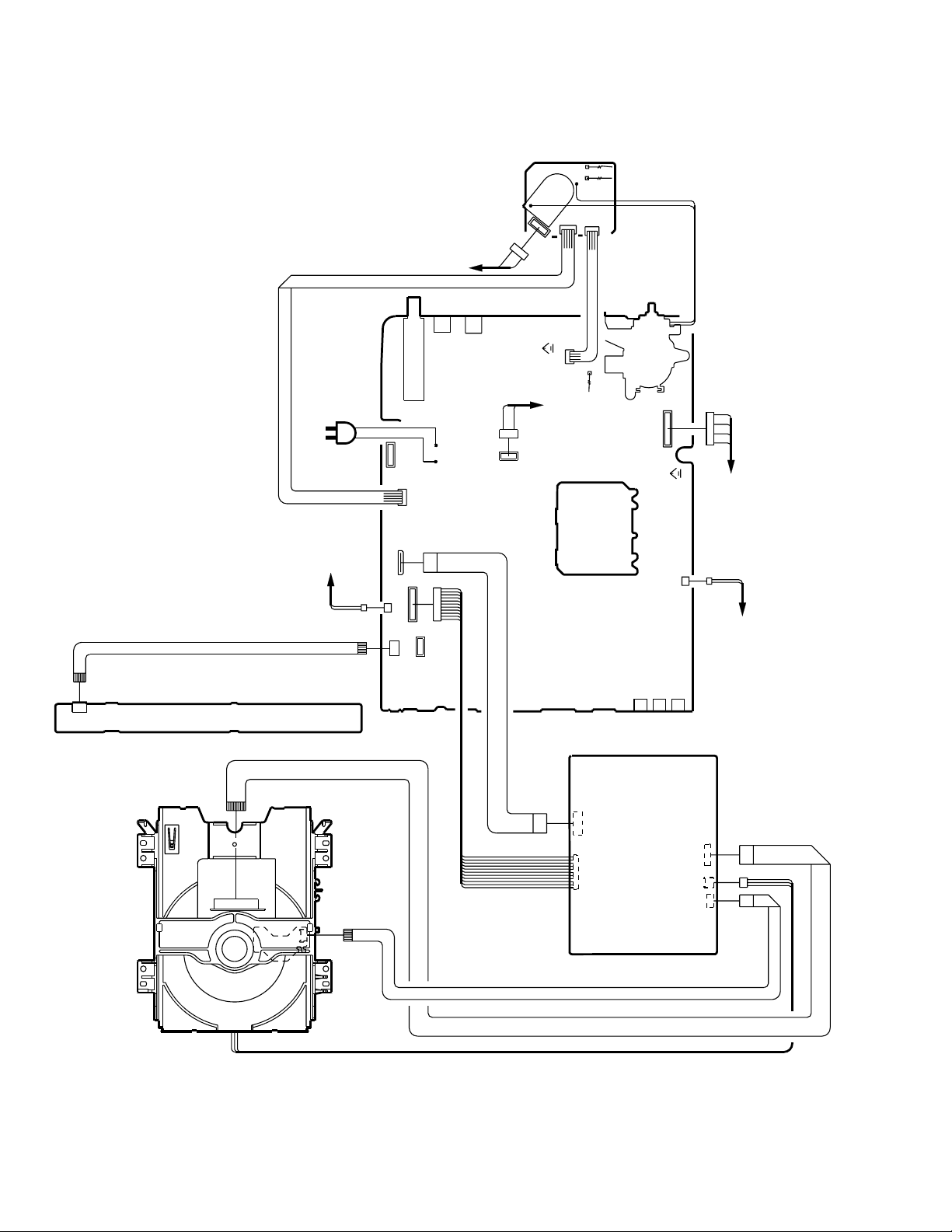
4.!ELECTRICAL!ADJUSTMENT!PARTS!LOCATION!GUIDE!(WIRING!CONNECTION)
CRT PCB
TP022
TP024
J801
CP801
CD801
CRT
CD802
CP802B
CP803B
CD803
CP751
CD751
OPERATION PCB
AC IN
SPEAKER
CD301
CP101
CP8002
CP301
CP8001
CP104
TU001
CD3800
CP802A
CP4201
J4201
J4203
CP3800
CD8501
VR3800
CP803A
CR
AV PCB
FB401
TP401
T
CP401
CRT
CD302
SPEAKER
J2202
VR402
CP302
J2203
J2204
24
DVD DECK
No. 52133
CP8502
CD8505
CD2301
CD2001
CD2302
CP2001
CP2302
CP2301
DVD PCB
Page 25

GUIDE!FOR!REPAIRING
IC!DESCRIPTION
AV!PCB!OEC6073A!(IC101)
No. Symbol I/O Logic Function
1 VSS - - Negative power supply (Ground)
2 TV/DVD Output 1
3 PROTECT Output 1
4 TV MUTE Output 1 Volume muting output
5 DVD POWER Output 1 DVD power control output
6 DVD RESET Output 0 Enforced reset output for DVD
7 TV POWER Output 1 Power control output
8
DEGAUSS
9 UART CLOCK Output 1 The asynchronous clock output
10 UART START BIT Input 1 The entry for the asynchronous Start bit detection
11 RX Input - The communication DATA entry from the side of DVD
12 TX Output - The communication DATA output to the side of DVD
13 UART CLOCK IN Input - The asynchronous clock Input
14 H CONTROL Output 1
15 X-RAY IN Input - X-RAY detection input (nom. 0V)
16 AFT Input 1 Voltage of tuning input
17 KEY1 Input 0 Voltage of the TV button input
18 KEY2 Input 0 Voltage of the TV button input
19 AV2 Output 1
20 AV1 Output 1
21 IIC BUS OFF Input 0 Serial clock/data stop input
22 OSD R Output 1 Red output of RGB image output
23 OSD G Output 1 Green output of RGB image output
24 OSD B Output 1 Blue output of RGB image output
25 OSD Y/BLK Output 1 Fast blanking control signal
26 Hsync Input 0 Horizontal synchronization input
27 Vsync Input 0 Vertical synchronization input
28 OVDD - - Positive power supply (+5V nom.)
29 OVCC - - Negative power supply (Ground)
30 TEST Input - Test input (connects with Ground)
31 XIN Input - Connect the main crystal.
32 XOUT Output - Connect the main crystal.
33 RESET Input 0 System reset voltage input
34 POWER FAIL Input 0 Power failure detection input
35 REMOCON Input 0 Remote control input
36 SD Input 0 Synchronization detector input
37 SCL Output - Serial clock output
38 SDA In/Output - Serial data Input/output
39 VSS - - Negative power supply (Ground)
40 VIDEO IN 1 Input - Picture signal input for the Closed Caption (2Vp-p)
41 VIDEO IN 2 Input - Picture signal input for the Closed Caption (2Vp-p)
42 VDD - -
Output 1 Degauss output
TV/DVD picture signal changing output
Output terminal for protect from high-voltage remaining
Output terminal for Horizontality Control
TV/DVD picture signal changing output
TV/DVD picture signal changing output
Positive power supply (+5V nom.)
AV-20FD24
No. 52133
25
Page 26

AV-20FD24
(DVD SECTION)
NO OPEN/CLOSE
TROUBLESHOOTING GUIDE
Check display DVD OSD.
No
Check the circuit around
IC2001.
No
Change DVD LOADER.
Yes
Yes
Check connection CP2301.
No
No
Yes
Connection try again CP2301.
Change IC2001.
26
No. 52133
Page 27

DVD NO PICTURE
AV-20FD24
Check connection CP8502.
Yes
Check input signal at pins
1, 3 and 5 of CP8502.
No
Check oscillation of X4001.
Yes
Change IC4003.
No
Yes
No
Connection try again CP8502.
Check IC601 and IC4202.
Change X4001.
Yes
Change IC4002.
Yes
Change IC2001.
No. 52133
27
Page 28

AV-20FD24
DVD, CD NO PLAY
("BLUE BACK LOGO" SHOW ON
SCREEN.)
After reading,check
"INCORRECT DISC"
display.
Yes
No
When play, check the
DECK MOTOR moving.
No
Check connection CD2301.
No
Connection try again CD2301.
Yes
Yes
Change DVD DECK.
Change DVD DECK.
Check connection CP2001.
Yes
Check DVD DECK connection bend
or short ?
No
Connection try again CP2001.
28
No. 52133
Page 29

INSTABILITY DVD MODE
AV-20FD24
Check connection CD8502.
Yes
Check DVD DECK
connection bend or
short ?
Yes
Check connection
CD2301, CD2001.
Yes
No
No
No
Connection try again CD8502.
Change DVD DECK.
Connection try again
CD2301, CD2001.
Change DVD DECK.
No. 52133
29
Page 30

AV-20FD24
(TV SECTION)
POWER DOES NOT TURN ON (1)
When turning on the
power switch, does the
LED light ?
Yes
Is the signal at
pin 23 of IC601
normal?
Yes
Check +B line?
Yes
Is the heater of CRT
lighted?
No
No
No
No
Is the voltage at pin 28 of
IC101 of 5.0V?
Yes
Check IC101 and
peripheral circuit.
No
Check AT5V line and
peripheral circuit.
Check the IC601 and
peripheral circuit.
Check Q401, Q405, Q406
and peripheral circuit.
Check CRT TUBE and heater circuit.
Yes
Check IC601 and peripheral circuit.
30
No. 52133
Page 31

POWER DOES NOT TURN ON 2
AV-20FD24
F3800 OK ?
Yes
Is the voltage at
C3815 DC175V ?
Yes
Is the check feed back
switching circuit ok?
Yes
Check Q3803, Q3802 and
peripheral circuit.
No
No
No
Change F3801.
Check R3817 and D3808, D3809,
D3815, D3816 peripheral circuit.
Check Q3800, IC3800 and
peripheral circuit.
No. 52133
31
Page 32

AV-20FD24
GOOD PICTURE BUT NO SOUND
Is CD301 and CD302
inserted?
Yes
Is the voltage at pin 10
of IC351 DC 21.5V ?
Yes
Is the voltage at pin 11
of IC351 DC 10.3V ?
Yes
Is the voltage at pin 8
of IC351 LESS than DC
2.0V ?
No
No
No
No
Insert CD301 and CD302.
Check Sound+B line and
peripheral circuit.
Check P.CON+12V line and
peripheral circuit.
Check IC101 and peripheral circuit.
Yes
Is the AUDIO OUT
signal at pins 7 and 11 of
IC301?
Yes
Check IC301, speaker and
Earphone jack.
No
Check A_OUT_L, A_OUT_R line
and peripheral circuit.
32
No. 52133
Page 33

NO PICTURE
AV-20FD24
Are the Brightness and
Contrast set to NORMAL?
Yes
Is the voltage at pin 8
of IC1501 DC 5V ?
Yes
Is there a waveform at
pin 4 of IC1501.
Yes
Is there a waveform at
pin 7 of IC601.
No
No
No
No
Adjust Brightness and Contrast.
Check P. CON + 5V line.
Check IC4202 and peripheral circuit.
Check q1501 and peripheral circuit.
Yes
Is the voltage at pins
21 and 13 of IC601
DC 9V ?
Yes
Is the voltage at pins 36 of
IC601 DC 5V ?
Yes
Is TV, AV and DVD
MODE of all NG?
Yes
No
No
No
Check P. CON + 9V line.
Check CHROMA +5V line.
Check NG MODE circuit line.
Check IC601 and peripheral circuit.
No. 52133
33
Page 34

AV-20FD24
NO COLOR
Is the color set to normal ?
Yes
Is the color signal received ?
Yes
Is the wavefrom at pin 35
of IC601 normal ?
Yes
Check peripheral circuit of IC601.
No
No
No
Adjust the color.
Receive the color signal.
Check the peripheral circuit of X601.
34
No. 52133
Page 35

ONLY A LINE APPEARS
AV-20FD24
Is the signal at pin 19 of
IC601 normal ?
Yes
Is there a waveform at
IIC BUS line normal?
Yes
Is the signal at pin 5
of IC401 normal?
Yes
Check DY and peripheral circuit.
No
No
No
Check IC401 and VCC
25V line.
Yes
Check IC401 and peripheral circuit.
No
Check the peripheral circuit of IC601.
Check IIC BUS line control IC.
Check FB401 and peripheral circuit.
OSD SCREEN DOES NOT APPEAR
Is there a waveform at pins
22, 23, 24 and 25 of IC101?
Yes
Is there a waveform at pins
54, 55, 56 and 57 of IC601 ?
Yes
Check pin 25 of IC101 and IC601
peripheral circuit.
No
No
No. 52133
Check IC101or IC601 and
peripheral circuit.
Check IC601 at pins 20, 21 and 22
peripheral circuit.
35
Page 36

AV-20FD24
SERVICE!NOTE!:
36
No. 52133
Page 37

JVC SERVICE & ENGINEERING COMPANY OF AMERICA
DIVISION OF JVC AMERICAS CORP.
www.jvcservice.com(US Only)
JVC CANADA INC.
Head office : 21 Finchdene Square Scarborough, Ontario M1X 1A7 (416)293-1311
(No. 52133)
Printed in Japan
200306WPC
 Loading...