


ANLEITUNG ZUM GEBRAUCH - INSTRUCTION BOOKLET |
DE |
GASHERDE
GAS COOKERS
JGS 1000
JGS 1010
JGS 3010
JGS 5010
JGS 5110
2
ENGLISH
DISPOSAL OF PACKING
HINTS ON THE DISPOSAL OF PACKING
Except for wooden material, packing and auxiliary material of Juno Major Appliances are recyclable and on principle should be handed over to recycling stations.
- After delivery to your premises packing of major appliances may be returned to our contract forwarders. Same will then initiate forwarding on for reuse or disposal.
In case of not making use thereof we recommend to put:
-paper, cardboard and corrugated board as well as
-plastic packing material and
-metal packing material
into the collecting bins provided for this purpose. As long as same are not existing in your living area, add the material to your rubbish.
Only recyclable plastics are |
|
|
|
allowed by Juno as auxiliary |
02** |
05 |
06 |
packing material, e.g.: |
PE |
PP |
PS |
|
The samples read:
PE for polyethylene**02 = PE-HD:04 PE-LD PP for polypropylene
PS for polystyrene
INSTRUCTIONS FOR USE
IMPORTANT HINTS
●The connection of the gas cooker must be carried out by an approved gas fitter, only.
●When connecting electric appliances to sockets in the near of a cooker make sure that connecting leads will not get in touch with hot open burners or get jammed by the hot oven door.
●Overheated fats and oils may rapidly flare up on the hot open burners. Dishes with fat or oil, such as French fries must therefore be prepared under control, only.
●Do neither line the oven with aluminium foil nor place any baking/roasting vessels direct on the oven bottom. The heat accumulation resulting thereby may destroy the enamel. Such damages of enamel are not covered by our guarantee.
●Do not use the gas burners for space heating!
●When operating the oven do always fold up the top lid.
●The typeplate can be seen after opening of the oven door at the right side.
●In case of any trouble do shut off the supply of energy! Call the after-sales-service!
●To maintain the safety of the appliance make sure that repairs, in particular of live gas conducting components, are exclusively carried out by expert gas fitters. With any trouble call the after-sales- service.
●Do carefully keep the instructions for installation and use!
During the operation the oven door is slightly heated up because of the structure of the oven door crystal and of the adjacent parts. Do make sure, therefore, that playing children will not approach the oven. If there be a socket in the direct vicinity of the oven, make sure that cables
of electric appliances will not get in touch with hot open burners or jammed in the oven door.
The present instruction for use is valid only for countries the abbreviation of which is shown on the front page of the instructions as well as on the appliance.
35

TABLE OF CONTENTS
Description of the appliance |
Page |
36 |
Control panel |
Page |
37 |
Technical data |
Page 38 |
|
Instructions for use |
Page |
39 |
Open burners |
Page 39 |
|
Oven |
Page 40 |
|
Use of the electric grill |
Page |
42 |
Hints on the use |
Page 42 |
Chart with cooking times |
Page 45 |
Cleaning and care |
Page 46 |
Installation instructions |
Page 48 |
Connection to the mains |
Page 50 |
Conversion to other type of gas |
Page 51 |
What to do, if ... |
Page 56 |
After-sales-service and spareparts |
Page 57 |
DESCRIPTION OF THE APPLIANCE
|
|
|
|
|
|
5 |
3 |
|
|
|
|
|
|
2 |
|
|
|
|
|
4 |
|
|
|
|
|
|
|
|
|
|
|
|
1 |
1 |
10 |
|
|
|
|
|
|
9 |
8 |
7 |
6 |
|
|
|
|
5 |
|
||||
|
|
|
|
|
|
6 |
|
|
|
|
|
|
7 |
|
|
|
|
|
|
8 |
|
|
|
|
|
|
9 |
|
|
|
|
|
|
10 |
Fig. 1
JGS 1000 - JGS 1010
JGS 3010 - JGS 5010
1.Control panel
2.Hob unit
3.Open burner
4.Pot rest
5.Top lid
|
|
|
|
5 |
3 |
|
|
|
|
2 |
|
|
|
4 |
|
|
|
|
|
|
|
|
1 |
1 |
10 |
|
|
|
|
98 |
7 |
65 |
|
|
|
|
|||
|
|
|
|
6 |
|
|
|
|
7 |
|
|
|
|
8 |
|
|
|
|
9 |
|
|
|
|
10 |
Fig. 2
JGS 5110
6.Oven
7.Oven door with window
8.Utensils drawer
9.Cover plate
10.Leveling leg
36

CONTROL PANEL
MOD. JGS 1000-1010-3010-5010
Fig. 3
1
10
9
8
7
6
5
3
4
2
1 |
2 |
3 |
4 |
5 |
6 |
7 |
8 |
1.Electronic ignition of open burners and oven - with model JGS 5010, only
2.Oven light (except for models JGS 1000/1010)
3.Knob for rear left open burner - heavy-duty burner
4.Knob for front left open burner - standard burner
5.Knob for front right open burner - cooking burner
6.Knob for rear right open burner - standard burner (except for models JGS 1000)
7.Knob for oven burner (and electric grill in model JGS 5010)
8.Indicator lamp (with model JGS 5010, only)
MOD. JGS 5110
1 
10
9
8
7
6
5
3
4
2
1 |
2 |
3 |
4 |
5 |
6 |
7 |
8 |
Fig. 4
1.Electronic ignition of open burners and oven
2.Oven light
3.Knob for rear left open burner - heavy-duty burner
4.Knob for front left open burner - standard burner
5.Knob for front right open burner - cooking burner
6.Knob for rear right open burner - standard burner
7.Knob for oven burner
8.Indicator lamp
37

TECHNICAL DATA
MODELL |
|
|
JGS 1000 |
JGS 1010 |
JGS 3010 |
JGS 5010 |
JGS5110 |
|
|
|
|
|
|
|
|
Sizes: H = mm |
|
|
850 |
850 |
850 |
850 |
850 |
W = mm |
|
|
500 |
500 |
500 |
500 |
600 |
D = mm |
|
|
600 |
600 |
600 |
600 |
600 |
with top lid closed |
H = mm |
|
870 |
870 |
870 |
870 |
870 |
with top lid opened |
H = mm |
|
1430 |
1430 |
1430 |
1430 |
1430 |
height adjustable by |
mm |
|
15 |
15 |
15 |
15 |
15 |
|
|
|
|
|
|
|
|
Output of gas burners |
|
|
|
|
|
|
|
Heavy-duty burner |
|
W |
|
|
3000 |
|
|
Standard burner |
|
W |
|
|
2000 |
|
|
Cooking burner |
|
W |
|
|
1000 |
|
|
Oven burner |
|
W |
|
|
3000 |
|
|
|
|
|
|
|
|
|
|
Operation |
|
|
|
Natural gas LPG |
|
||
|
|
|
|
|
|
|
|
Maximum output |
|
Natural gas E |
|
|
1.05 m3/h |
|
|
|
|
LPG |
|
|
800 g/h |
|
|
|
|
|
|
|
|
|
|
Connection to gas supply |
|
|
|
R 1/2“ |
|
|
|
|
|
|
|
|
|
|
|
Nominal pressure |
|
Natural gas |
|
|
20 mbar |
|
|
|
|
LPG |
|
|
50 mbar |
|
|
|
|
|
|
|
|
|
|
Oven thermostat |
|
|
|
from 150°C to 260°C |
|
||
|
|
|
|
|
|
||
Connection to the mains (50 cycles) |
|
|
230 V |
|
|
||
|
|
|
|
|
|
|
|
Output of electric grill |
|
kW |
- |
- |
- |
1,8 |
1,8 |
|
|
|
|
|
|
|
|
Accessories |
|
|
Plate for |
Plate for |
Plate for |
Plate for |
Plate for |
|
|
|
pastry |
pastry |
pastry |
pastry |
pastry |
|
|
|
Pot rest |
Pot rest |
Pot rest |
Pot rest |
Pot rest |
|
|
|
|
|
|
Protective |
Protective |
|
|
|
|
|
|
screen for |
screen for |
|
|
|
|
|
|
knobs |
knobs |
|
|
|
|
|
|
|
|
The gas hob is registered acc. to German Standard DIN-DVGW.
CATEGORY II 2 ELL 3 B/P
This appliance corresponds to the following
E.E.C. regulations:
-73/23 - 90/683 (low voltage guideline):
-89/336 (EMC guideline):
-90/396 (gas guideline):
-93/68 (general instructions): and subsequent changes.
PRODUCER: ELECTROLUX HAUSGERÄTE
Rennbahnstraße 72-74
60528 Frankfurt
38
INSTRUCTIONS FOR USE
OPEN BURNERS
●The open burners are thermoelectrically secured in a way that the feed of gas will automatically be shut off when the flame goes out.
●Lay the burner caps always exactly on the burner chalice.
●The slots of the burner chalice must not be obstructed.
●The burner caps are enamelled
●Operate the open burners with items to be cooked put on, only!
PUTTING INTO OPERATION
OF THE OPEN BURNERS
To ignite the gas burner bring a flame (matchstick, lighter or igniter) to the desired burner, with that push the corresponding rotary knob quite in and turn it counterclockwise up to the position for maximum temperature. As soon as the burner is ignited, set the gas flame as required.
In case of models with integrated automatic ignition push the ignition button, which is marked by a small spark symbol, at the same time quite push in the corresponding rotary knob and turn it counterclockwise up to the position for maximum temperature.
Because of pushing the ignition knob an ignition spark will jump over to the burner and ignite it. After ignition of the flame keep the rotary knob pushed in for about 5 seconds; this time is required to heat up the „temperature sensor“ (fig. 5, letter D) and to switch off the safety valve, that otherwise would interrupt the feed of
gas. Afterwards check whether the flame is uniform and turn the rotary knob to the desired strength.
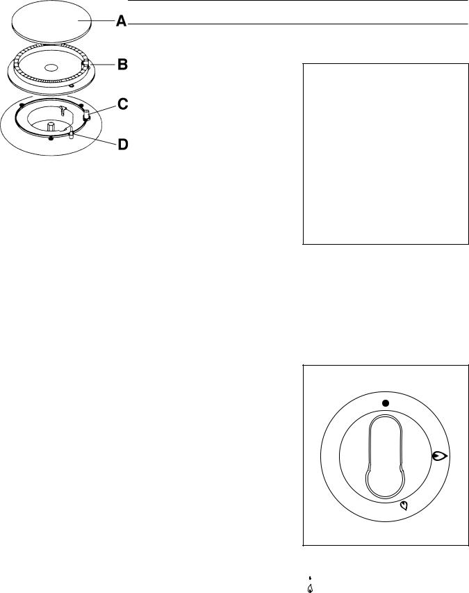
In case the burner will in spite of several trials not ignite, make sure that the flame distributor crown (fig. 5, letter B) and the burner cap (fig. 5, letter A) are correctly laid on.
To interrupt the gas feed turn turn the rotary knob in clockwise direction up to position „●„.
When using fat or oil you must not leave it out of visual control during the cooking procedure, as it may flare up when being heated.
Fig. 5
Fig. 6
FO 0204
Open burner
ABurner cap
BFlame distributor crown
CSpark plug
DTemperature sensor
● Gas feed closed
 High-burner Low-burner
39

COOKING ON THE OPEN BURNERS
When switching on the open burners for first-boiling/ frying, start at first with a big flame, and
afterwards set back to a small flame for cooking on. The pot size must be chosen in a way that the flames will not exceed the pot rim. You may use pots of at least 240 to 260 mm diameter with the
heavy-duty burner, pots of at least 200 to 220 mm diameter with a standard burner, and pots of about 160 mm diameter and smaller with the auxiliary burner.
Always put the dishes in the middle of the open burner.
PRESERVATION
Most convenient is preserving in a water bath in a big preserving pot on the heavy-duty burner.
Prepare the glasses in the usual manner. Make use of commercial preserving glasses with rubber ring and glass lid. Glasses with screw cap or bayonet catch and metal boxes must not be used.
Put the glasses in the water bath, not, however, on the pot bottom, but e.g. on a wire shelf. The glasses should be about ò of the height in the water bath
Upon reaching the boiling of the water set the flame smaller in a way that the water keeps on slightly boiling. In preserving pots without a thermometer the firstboiling time is calculated from the start of boiling of the water.
OVEN
●The oven burner is thermoelectrically secured in a way that the feed of gas will automatically be cut off if the flame goes out.
●The oven temperature is thermostatically controlled. After ignition the oven burner performs with full output until reaching the temperature set. Afterwards the thermostat reduces the output to the value required for keeping the temperature set.
●This control is effective with the door closed, only.
●The oven bottom can be removed for cleaning.
PRIOR TO FIRST USE
●Remove all accessories from the oven.
●Clean eneamel and glass surfaces with a wet cloth.
●After connection of the appliance operate the oven for about 1 hour at max. temperature setting (see paragraph: Putting into operation of the oven burner). The smell resulting thereby will be safe if the room is adequately ventilated.
●Afterwards wipe out the oven with a wet cloth and dry.
40
PUTTING INTO OPERATION
OF THE OVEN BURNER
●Attention! When operating the oven burner the ceiling slide must be pushed in against stop.
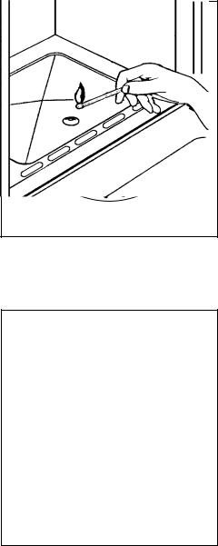
●The oven burner is ignited with the door opened.
●Turn the oven control knob to the left in porition 10, push in against stop, and ignite the gas flowing out. After ignition keep the control knob pushed in for about 5 more seconds until the temperature sensor is sufficiently heated and the flame remains stable. Afterwards the control knob can be set to the position desired between 1 and 10.
●Watch the flame picture. If the flame goes out, repeat the ignition procedure.
Models with integrated automatic ignition
●Push in the knob for oven/electric grill, turn from the right to the left up to highest marking and keep the knob pushed in.
●At the same time one pushes the button for the electronic ignition in order to generate sparks. Keep the knob pushed in until appearance of the flame (one spark will be generated after each second).
●To switch off the burner turn the knob to position „ ●„ (OFF)
TEMPERATURE SETTING
In correspondence with the items to be baked/roasted and after ignition turn the oven knob to the required temperature setting from 1 to 10
Abb. 7
Fig.. 8
1
10 |
2 |
|
9 |
8 |
|
|
|
3 |
|
7 |
6 |
5 |
4 |
|
|
|
|
|||
|
|
|
|
|
á Closed position (off)
1-10 Operating position of oven burner
FO 1079
Ignition of the oven burner
Position |
1 |
2 |
3 |
4 |
5 |
6 |
7 |
8 |
9 |
10 |
|
|
|
|
|
|
|
|
|
|
|
Temperature |
140°C |
150°C |
160°C |
180°C |
190°C |
200°C |
220°C |
230°C |
240°C |
260°C |
|
||||||||||
|
|
|
|
|
|
|
|
|
|
|
41
 Loading...