


M5 and M10 Internet
Routers
Hardware Guide
Juniper Networks, Inc.
1194 North Mathilda Avenue
Sunnyvale, California 94089
USA
408-745-2000
www.juniper.net
Part Number : 530–007247–01, Revision 3

This product includes the Envoy SNMP Engine, developed by Epilogue Technology, an Integrated Systems Company. Copyright
© 1986-1997, Epilogue Technology Corporation. All rights reserved. This program and its documentation were developed
at private expense, and no part of them is in the public domain.
This product includes memory allocation software developed by Mark Moraes, copyright © 1988, 1989, 1993, University of Toronto.
This product includes FreeBSD software developed by the University of California, Berkeley, and its contributors. All of the documentation and
software included in the 4.4BSD and 4.4BSD-Lite Releases is copyrighted by the Regents of the University of California. Copyright © 1979, 1980,
1983, 1986, 1988, 1989, 1991, 1992, 1993, 1994. The Regents of the University of California. All rights reserved.
GateD software copyright © 1995, the Regents of the University. All rights reserved. Gate Daemon was originated and developed through release
3.0 by Cornell University and its collaborators. Gated is based on Kirton’s EGP, UC Berkeley’s routing daemon (routed), and DCN’s HELLO routing
protocol. Development of Gated has been supported in part by the National Science Foundation. Portions of the GateD software copyright © 1988,
Regents of the University of California. All rights reserved. Portions of the GateD software copyright © 1991, D. L. S. Associa tes.
This product includes software developed by Maker Communications, Inc., Copyright © 1996, 1997, Maker Communications, Inc.
Juniper Networks is registered in the U.S. Patent and Trademark Office and in other countries as a trademark of Juniper Networks, Inc. ERX,
ESP, E-series, Internet Processor, J-Protect, JUNOS, JUNOScript, JUNOSe, M5, M7i, M10, M10i, M20, M40, M40e, M160, M-series, NMC-RX, SDX,
T320, T640, and T-series are trademarks of Juniper Networks, Inc. All other trademarks, servicemarks, registered trademarks, or registered
service marks
Copyright © 2003, Juniper Networks, Inc. All rights reserved.
M5 and M10 Internet Routers: Hardware Guide
Copyright © 2003, Juniper Networks, Inc.
All rights rese
are the property of their respective owners. All specifications are subject to change without notice.
rved. Printed in USA.
Writ er : Tony Ma uro
Editor: Stella
Illustrator: Faith Bradford
Covers and Template Design: Edmonds Design
Revision History
30 June 2003—Corrected and added component information.
07 October 2002—Corrected and added new component information.
12 March 2002—New edition—Changed book name and added PIC-related information.
03 Decembe r 2001—Fourth edition—Corrected AC power measurements.
10 May 2001—Third e
29 September 2000—Second edition—Corrected AC plug figure.
27 July 2000—First edition.
The information in this document is current as of the date listed in the revision history.
Juniper Networks a
otherwise revise this publication without notice.
Products made or so
M160, and T320 routers, T640 routing node, and the JUNOS and SDX-300 software) or components thereof might be covered by one or more of the
following patents that are owned by or licensed to Juniper Networks: U.S. Patent Nos. 5,473,599, 5,905,725, 5,909,440, 6,192,051, 6,333,650, 6,359,479,
6,406,312, 6,429,706, 6,459,579, 6,493,347, 6,538,518, 6,538,899, 6,552,918, 6,567,902, 6,578,186, and 6,590,785.
YEAR 2000 NOTICE
Juniper Networks hardware and software products are Year 2000 compliant. The JUNOS software has no known time-related limitations through the year
2038. However, the NTP application is known to have some difficulty in the year 2036.
Hackell
dition—Added four-post rack mounting instructions.
ssumes no responsibility for any inaccuracies in this document. Juniper Networks reserves the right to change, modify, transfer or
ld by Juniper Networks (including the ERX-310, ERX-705, ERX-710, ERX-1410, ERX-1440, M5, M7i, M10, M10i, M20, M40, M40e,
ii

Table of Con
tents
About This Manual .......................................... ............................................... ...... xv
Objectives
Audience.......................................... ............................................... ...... xv
Document Org
Documentation Conventions. ............................................... .........................xvi
List of Techni
Documentation Feedback ............... .............................................. ...............xix
How to Request S
Part 1
Product Overview
Chapter 1
System Overvi
System Description .............. .............................................. ........................ 3
Field-Replac
Safety Requirements, Warnings, and Guidelines ........................ ............................. 4
................................ ............................................ ................. xv
anization ......................... ............................................ .........xvi
General Conve
Notes, Cautions, and Warnings.............................................. ...................xvii
............................... ........................................... ........................ 3
ew
ntions................... .............................................. ............xvi
cal Publications.......................................................... ..............xvii
upport................. ............................................ .................xix
eable Units (FRUs).......................... ............................................ .. 3
Chapter 2
Hardware Component Overview .. ............................................... .......................... 5
Chassis ................... .............................................. ................................ 5
Packet Forwarding Engine.......... .............................................. ..................... 8
Midplane ................. ............................................ ............................. 8
Physical Interface Cards (PICs)........ ........................................... ................ 9
PIC Components................................................... ......................... 10
Flexible PIC Concentrators (FPCs) ............................................. ................. 10
Forwarding Engine Board (FEB)..................... ............................................ 10
FEB Components .............................. ............................................ . 11
Routing Engine........................... .............................................. ............... 12
Routing Engine Components................................................ .................... 13
Craft Interface.............. ............................................... ............................ 14
Alarm LEDs and Lamp Test Button ...................... ....................................... 15
Routing Engine Interface Ports and Status Indicators................... ....................... 15
PIC Offline Buttons ....................... .............................................. ......... 16
Ta b l e o f C on t e nt s
iii

Power Supplies...................... .............................................. .................... 16
AC Power Supply.................................... ............................................. 17
DC Power Supply ...................... .............................................. ............ 18
Power Supply LEDs and Self-test Button.................... .................................... 19
Fan Tray .......................................... ............................................... ...... 19
Cable Management System . ... ... ... ... ... ... ... ... ... ... ... ... ... ... ... ... ... ... ... ... ... ... ... ... . 20
Chapter 3
JUNOS Internet Software Overview ............................. ....................................... 21
Routing Engine Software Components ............... .............................................. . 21
Routing Protocol Process.............. .............................................. ............ 22
IPv4 Routing Protocols ...................... .............................................. . 22
IPv6 Routing Protocols ...................... .............................................. . 24
Routing and Forwarding Tables ..... .............................................. ......... 24
Routing Policy.................................. ............................................. 25
VPNs...................... ............................................... ......................... 26
Interface Process............................... ............................................ ...... 26
Chassis Process ....... ............................................... ............................ 26
SNMP and MIB II Processes ................... ............................................ ...... 26
Management Process. . .. . .. . .. . .. . .. . .. . ... ... ... .. . .. . ... ... ... ... ... ... ... ... ... ... ... ... ... .. 27
Routing Engine Kernel............................................... ............................ 27
Tools for Accessing and Configuring the Software.................................................. .27
Tools for Monitoring the Software..................... .............................................. .27
Software Upgrades.................................. .............................................. .... 28
Chapter 4
System Architecture Overview ... ............................................... ......................... 29
Packet Forwarding E
Data Flow through the Packet Forwarding Engine ............................... .............. 30
RoutingEngineArch
Routing Engine Functions ..................................... .................................. 32
ngine Architecture............ .............................................. .... 29
itecture..................... ............................................... ...... 31
Part 2
Initial Installation
Chapter 5
Prepare for Router Installation......... .............................................. .................... 37
Rack Requirements
Rack Size and Strength ................... .............................................. ......... 37
Spacing of Mounting
Connection to Building Structure ................................... ............................ 39
Clearance Requirem
Router Environmental Tolerances..................... .............................................. . 40
Fire Safety Requirem
Fire Suppression .......................... .............................................. ......... 41
Fire Suppression Equ
................................. ............................................ ...... 37
Holes............................................. ......................... 39
ents for Airflow and Hardware Maintenance.................................. 40
ents............. ............................................... ................. 41
ipment .................................. .................................. 41
iv M5 and M10 Internet Routers Hardware Guide

Power Guidelines, Requirements, and Specifications ................ ............................... 42
Site Electrical Wiring Guidelines ........... ............................................... ...... 43
Distance Limitations for Signaling ............. ............................................ 43
Radio Frequency Interference ................ ............................................ . 43
Electromagnetic Compatibility.............................. ............................... 43
Router Power Requirements ........................................ ............................ 43
AC Grounding and Power Cord Specifications................................. ................. 45
DC Grounding, Connection, and Cable Specifications ................ ......................... 46
Network Cable Specifications and Guidelines ........................... ............................ 48
Fiber Optic and Network Cable Specifications ....... .......................................... 48
Signal Loss in Multimode and Single-Mode Fiber-Optic Cable................................. 48
Attenuation and Dispersion in Fiber-Optic Cable ..................... ......................... 49
Calculating Power Budget for Fiber-Optic Cable....................... ......................... 49
Calculating Power Margin for Fiber-Optic Cable............................ .................... 50
Attenuate to Prevent Saturation at SONET/SDH PICs .......................................... 51
Cable Specifications for Routing Engine Management Interfaces ... ... ... ... ... ... ... ... ... ... ... . 52
Site Preparation Checklist ........................................ .................................... 52
Chapter 6
Unpack the Router............ ............................................... .................................... 55
Tools Required ... .............................................. ....................................... 55
Unpack the Router ............................... ............................................... ...... 55
Choose Front or Cente
r Mounting ....................................... ............................ 57
Chapter 7
Install the Router ................ .............................................. .................................. 59
Tools and Parts Required ...................... .............................................. ......... 59
Install the Chassis into the Rack............................... ....................................... 59
Chapter 8
Connect the Router and Perform Initial Configuration............... ....................... 61
Tools and Parts Required ...................... .............................................. ......... 61
Connect the Router to Management Devices. . .. . ... ... ... ... ... ... ... ... ... ... . .. . .. . .. . .. . .. . .. . .. 61
Connect to a Network for Out-of-Band Management ... ... . .. . .. . .. . .. . .. . .. . .. . .. ... . .. . .. . .. 62
Connect to a Management Console or Auxiliary D evice . .. . .. . .. . .. . ... ... ... ... ... ... ... ... .. 63
Connect PIC Cables .................................... ........................................... .... 63
Provide Power to the Router................................... ....................................... 65
Connect Power to an AC-Powered Router ............................. ......................... 65
Connect Power to a DC-Powered Router.................................................. ...... 66
Power On the Router ..................... .............................................. ......... 67
Configure the JUNOS Internet Software............... ........................................... .... 69
Ta b l e o f C o n t e n t s
v

Part 3
Hardware Maintenance, Replacement, and Troubleshooting
Procedures
Chapter 9
Maintain Hardware Components .......................... .............................................. . 75
Routine Maintenance Procedures.......... .............................................. ............ 75
Maintain the Fan Tray.......................... .............................................. ......... 75
Maintain Packet Forwarding Engine Components............................ ....................... 76
Maintain the FEB.......................... .............................................. ......... 76
Maintain PICs and PIC Cables. ........................................... ....................... 76
Maintain the Power Supplies ....................... .............................................. .... 78
Maintain the Routing Engine ............................. ............................................ 79
Chapter 10
Replace Hardw
are Components
Tools and Parts Required ...................... .............................................. ......... 81
Replace the Fa
Remove the Fan Tray .................. ........................................... ............... 82
Install the Fan
Replace Packet Forwarding Engine Components..................... ............................... 84
Replace the FEB
Replace a PIC ..................................... .............................................. . 87
Replace PIC Cable
Replace an SFP.............................. ............................................... ...... 95
Replace Power Syste
Replace an AC Power Supply............................. ....................................... 98
Disconnect and Conne
Replace an AC Power Cord ....................... ........................................... ...103
Replace a DC Power Supp
Disconnect and Connect DC Power............................................... .............108
Replace Routing Engine C
Remove and Insert the PC Card.......................................... ...................... 112
n Tray.............................................. .................................... 82
Tray.......... ............................................ ......................... 83
Remove the FEB .......................... .............................................. .... 85
Install the FEB .................................... .......................................... 8
Remove a PIC.... ............................................... ............................ 87
Install a PIC ............ .............................................. ....................... 89
Remove a PIC Cable... .............................................. ....................... 92
Install a PIC Cable
Remove an SFP ........................................... .................................. 95
Install an SFP .. .............................................. ............................... 96
m Components ........................................ ......................... 98
Remove an AC Power Sup
Install an AC Power Supply............................................. ...................100
Disconnect AC Power from the Router ........................ ...........................102
Connect AC Power to the
Remove a DC Power Supply......................... ......................................104
Install a DC Power Suppl
Disconnect DC Power from
Connect DC Power to the Router ................................. ........................ 110
Remove the PC Card ....... ............................................... ................ 113
................................ .......................................... 81
................................ ............................................ ...... 84
s ......... .............................................. ....................... 92
................................ .......................................... 93
ply ............ .............................................. .... 99
ct AC Power ...................... ...................................... 101
Router............................ ..............................102
ly ......................................... ...........................104
y........... ........................................... ...........106
the Router..... ..............................................109
omponents ........................... ................................... 112
6
vi M5 and M10 Internet Routers Hardware Guide

Insert the PC Card .. ............................................... ........................ 114
Replace the Routing Engine... ........................................... ...................... 115
Remove the Routing Engine ...................................... ........................ 115
Install the Routing Engine..................... ............................................ 116
Replace Connectors to Routing Engine Interface Ports ....................................... 118
Replace the Management E thernet Cable ... ... ... ... ... ... ... ... .. . ... ... ... ... ... ... ... 118
Replace the Console or Auxiliary Cable................................ ................... 119
Chapter 11
Troubleshoot Hardware Components ................... ........................................... ...121
Overview of Trou
Command-Line Interface ...................................... .................................121
LEDs .............................. ............................................... ................122
LEDs on the Craft Interface ............................................ ...................122
LEDs on Hardware C
Hardware and Interface Alarm Messages. . .. . .. . .. . .. . .. . .. . .. . .. . .. . ... ... ... ... ... ... ... ... .122
Juniper Networks T
Troubleshoot the Fan Tray............... .............................................. ..............124
Tro u b le s ho o t Pack
Troubleshoot the FEB............ ............................................ ...................125
Troubleshoot PICs.................................................... ...........................1
Troubleshoot the Power System............................... ......................................125
LED on Both Supplies I
LED on One Supply Is Off.. .............................................. ......................126
bleshooting Resources ...................................... ......................121
omponents.................................. ........................122
echnical Assistance Center ............................................. ...124
et Forwarding Engine Components............... ..............................124
s Off.............. ........................................... ...........126
Part 4
Appendixes
Appendix A
Safety and Regulatory Compliance Information.... ...........................................129
Definition of Safet
Safety Guidelines and Warnings............................................. ........................131
General Safety Guid
Qualified Personnel Warning................................ ..............................132
Restricted Access Ar
Prevent Electrostatic Discharge Damage ...................... ...........................134
Electrical Safety Gu
General Electrical Safety Guidelines ................... ...................................136
AC Power Electrical Sa
DC Power Electrical Safety Guidelines......... ...........................................137
Copper Conductors War
DC Power Disconnection Warning..................... ...................................138
DC Power Grounding Requ
DC Power Wiring Sequence Warning............ .........................................140
DC Power Wiring Terminat
Grounded Equipment Warning ................................... ........................142
In Case of Electrical Acc
Midplane Energy Hazard Warning .......... ..............................................143
Multiple Power Supplies D
y Warning Levels...................... ...........................................129
elines and Warnings ........ ..............................................131
ea Warning .... .............................................. ........133
idelines and Warnings.....................................................135
fety Guidelines ................................. ...................136
ning ..................................... ........................138
irements and Warning .......................................139
ions Warning ................ .................................141
ident ....... ........................................... ...........143
isconnection Warning ............. ...........................144
25
Ta b l e o f C on t e nt s
vii

Power Disconnection Warning...... ........................................... ...........144
TN and IT Power Warning........................... ......................................145
Installation Safety Guidelines and Warnings ............................................. .....146
Chassis Lifting Guidelines ........................ .........................................146
Installation Instructions Warning ........ ............................................ .....147
Rack-Mounting Requirements and Warnings.............................................147
Ramp Warning................................. ............................................151
Laser and LED Safety Guidelines and Warnings...............................................152
General Laser Safety Guidelines........................................ ...................152
Class 1 Laser Product Warning................................. ...........................153
Class 1 LED Product Warning. .............................................. ..............153
Laser Beam Warning .......... .............................................. ..............154
Radiation From Open Port Apertures Warning..................... ......................154
Maintenance and Operational Safety Guidelines and Warnings..............................155
Battery Handling Warning................................... ..............................155
Jewelry Removal Warning ................................... ..............................156
Lightning Activity Warning ........................................ ........................157
Operating Temperature Warning.......................................... ................158
Product Disposal Warning........................................... ......................159
Agency Approvals................ .............................................. ......................160
Compliance Statements for EMC Requirements................................. ...................161
Canada ........................... ............................................... ................161
European Community ....................................... ...................................161
Japan ........................................... .............................................. ...161
Taiwan.................... ............................................... ........................161
United States ................................ ............................................... .....162
Appendix B
Return the Router or Its Components ................................. ..............................163
Tools and Parts Required ...................... .............................................. ........163
Return Procedure ........................ .............................................. ..............163
Locate Component Serial Numbers ............. ............................................... .....164
FEB Serial Number ID Label................................................. ...................165
PIC Serial Number ID Label ...................... ..............................................165
Power Supply Serial Number ID Label............. ............................................166
Routing Engine Serial Number ID Label .......................................... .............167
Pack the Router for Shipment ......................................... ..............................168
Pack Components for Shipment ............................................ ........................169
Appendix C
Cable Connector Pinouts .... ............................................ ...................................171
RJ-45 Connector Pinouts
DB-9 Connector Pinouts for the Routing Engine AUX/MODEM and CONSOLE Ports... ... ... ... .171
RJ-48 Cable Pinouts for E
RJ-21 Cable Pinouts for Fast Ethernet 12-Port PIC..................................................175
for the Routing Engine MGMT Port.................................... ..171
1 and T1 PICs ......................................... ...................172
Part 5
Index ................................. ............................................ ......................................177
viii M5 and M10 Internet Routers Hardware Guide

Index
Index ................................. ............................................ ......................................179
Ta b l e o f C o n t e n t s
ix

x M5 and M10 Internet Routers Hardware Guide

List of Figures
List of Figur
Figure 1: Front of M5 Chassis..................................... .............................................. ................ 6
Figure 2: Fro
Figure 3: Rear of Chassis..................................... .............................................. ..................... 7
Figure 4: Mid
Figure 5: Forwarding Engine Board..................................................... ....................................... 12
Figure 6: Rout
Figure 7: Craft Interface ........................................... ............................................ ................. 14
Figure 8: AC Pow
Figure 9: DC Power Supply..................... ............................................ .................................... 18
Figure 10: Airf
Figure 11: Cable Management System .. . .. . .. . .. . .. . .. . ... ... ... ... ... ... ... ... ... . .. . .. . .. . .. . .. . .. . ... ... ... ... ... ... ... ... 20
Figure 12: Syste
Figure 13: Packet Forwarding Engine Components and Data Flow..... ............................................... ...... 31
Figure 14: Routin
Figure 15: Control Packet Handling for Routing and Forwarding Table Updates .. .......................................... 33
Figure 16: Typical
Figure 17: Chassis Dimensions and Clearance Requirements ................................ ............................... 40
Figure 18: AC Plug T
Figure 19: DC Power and Grounding Cable Connections................... .............................................. .... 47
Figure 20: Unpack th
Figure 21: Routing Engine Management Ports. ... ... ... ... ... ... ... ... ... ... ... . .. . .. . .. . .. . .. . .. . .. . .. . .. . .. . .. . .. . ... .. . .. . 62
Figure 22: Routing E
Figure 23: Console and Auxiliary Serial Port Connector................. ............................................... ...... 63
Figure 24: Attach Cab
Figure 25: Connect DC Power and Grounding Cables ...... .............................................. .................... 67
Figure 26: Remove the F
Figure 27: Install the Fan Tray ...... ............................................ .............................................. . 84
Figure 28: Remove the F
Figure 29: Install the FEB ........................... ............................................... ............................ 87
Figure 30: Remove a PIC............ ............................................ .............................................. . 8
Figure 31: Install a PIC ............................................ ............................................ ................. 92
Figure 32: Connect Fibe
Figure 33: Small Form Factor Pluggable (SFP) .. ... . .. ... . .. . .. . ... ... ... ... ... . .. . .. . ... ... ... ... ... ... . .. . .. . ... ... ... ... ... 95
Figure 34: Remove an AC Po
Figure 35: Install an AC Power Supply............................... .............................................. ...........101
Figure 36: Remove a DC Powe
Figure 37: Install a DC Power Supply............................. .............................................. ..............108
Figure 38: Connect Power C
Figure 39: Connect Power Cables to a DC Power Supply..... ............................................... ................ 112
Figure 40: Remove the PC Car
Figure 41: Insert the PC Card .... ............................................... .............................................. 115
Figure 42: Remove the Routi
Figure 43: Install the Routing Engine.................. ............................................... ........................ 118
Figure 44: Routing Engine In
Figure 45: Ethernet Cable Connector................................................ ......................................... 119
Figure 46: Serial Port Connec
Figure 47: Place a Component into an Electrostatic Bag ... .............................................. ...................135
Figure 48: Serial Number ID La
nt of M10 Chassis ............. ............................................ ........................................ 6
plane.................................................... .............................................. ............. 9
ing Engine.................... ............................................... .................................... 14
er Supply ........................................... .............................................. ............ 17
low through the Chassis ........................ ............................................... ................. 19
m Architecture ........................... .............................................. ....................... 29
g Engine Architecture .. .............................................. ....................................... 32
es
Center-Mount Rack.......................................................... ............................... 39
ypes. ............................................... .............................................. ......... 46
e Router..................... .............................................. ............................... 56
ngine Ethernet Cable Connector ......................... .............................................. . 63
le to a PIC ............................. .............................................. .................... 65
an Tray .......................................... ............................................... ...... 83
EB .................................... ............................................... ................. 86
r-Optic Cable to a PIC......................... .............................................. ......... 95
wer Supply ............................ ........................................... ..............100
r Supply................................. ........................................... ...........106
ables to a DC Power Supply........... ............................................ .............108
d ........................................ .............................................. ........ 114
ng Engine ..................................... .............................................. ... 116
terface Ports and Alarm Relay Contacts ................... ................................... 118
tor..................................... ........................................... ..............120
bel ............................... .............................................. ..............165
9
List of Figures
xi

List of Figures
Figure 49: FEB Serial Number ID Label ..................... ........................................... ......................165
Figure 50: PIC
Figure 51: AC Power Supply Serial Number ID Label ............ ............................................ ................166
Figure 52: DC Po
Figure 53: Routing Engine 333 Serial Number ID Label ....................................... ..............................167
Figure 54: Routi
Figure 55: Fast Ethernet 12-port PIC ..... ........................................... .........................................175
Figure 56: VHDCI
Serial Number ID Label ................ ............................................... ........................166
wer Supply Serial Number ID Label.......................................................... ..............167
ng Engine 600 Serial Number ID Label .................................... .................................168
to RJ-21 Cable............................................................. .................................175
xii M5 and M10 Internet Routers Hardware Guide

List of Tables
List of Tables
Table 1: Juniper Networks Technical Documentation ...................................... .....................................
Table 2: Field-Replaceable Units .................. .............................................. ................................ 4
Table 3: Chassis Physical Specifications ............................................. ........................................... 7
Table 4: Alarm LEDs and Lamp Test Button .................. ............................................... ................. 15
Table 5: Electrical Specifications for AC Power Supply...................................... .................................. 18
Table 6: Electrical Specifications for DC Power Supply ..................... .............................................. .... 18
Table 7: States for Power Supply LED................................................ .......................................... 19
Table 8: Router Environmental Tolerances .... .............................................. .................................. 40
Table 9: Component Power Requirements ....................... ............................................... .............. 44
Table 10: AC Power Cord Specifications .......... .............................................. ............................... 45
Table 11: DC Power and Grounding Cable Specifications... .............................................. .................... 46
Table 12: Estimated Values for Factors Causing Link Loss ...................... ........................................... .50
Table 13: Cable Specifications for Routing Engine Management Interfaces ... ... ... ... ... ... ... ... ... ... ... ... ... ... ... ... . 52
Table 14: Site Preparation Checklist ................... ............................................ ............................ 52
Table 15: Generic Inventory of Router Components.......... ............................................... ................. 56
Table 16: Tools and Parts Required ............ .............................................. .................................. 81
Table 17: Chassis Alarm Messages.. . .. . .. . .. . .. . .. . .. . .. . .. . .. . .. . .. . .. . .. . .. . .. . .. . .. . ... .. . .. . .. . .. . .. . .. . ... ... ... ... .. . ..123
Table 18: SONET/SDH Interface Alarm Messages .. . .. . .. . .. . .. . .. . .. . .. . .. . .. . .. . .. . .. . ... ... ... .. . .. . .. . .. . ... ... ... ...123
Table 19: RJ-45 Connector Pinout....................................... .............................................. ........171
Table 20: DB-9 Connector Pinout ......... .............................................. ......................................172
Table 21: RJ-48 Connector to RJ-48 Connector (Straight) Pinout ........................... .................................172
Table 22: RJ-48 Connector to RJ-48 Connector (Crossover) Pinout.................................. ........................173
Table 23: RJ-48 Connector to DB-15 Connector (Straight) Pinout ........................................... ................174
Table 24: RJ-48 Connector to DB-15 Connector (Crossover) Pinout...................... ...................................174
Table 25: RJ-21 Pin Assignments........................................ .............................................. ........176
List of Tables
xiii

List of Tables
xiv M5 and M10 Internet Routers Hardware Guide

About This Manual
This chapter provides a high-level overview of the M5 and M10 Internet Routers Hardware
Guide:
• Objectives on page xv
• Audience on page xv
• Document Organization on page xvi
Objectives
• Documentatio
n Conventions on page xvi
• List of Technical Publications on page xvii
• Documentation Feedback on page xix
• How to Request Support on page xix
This manual explains the hardware installation and basic troubleshooting for the M5 and
M10 Internet routers. It contains procedures for preparing your site for router installation,
unpacking and installing the hardware, starting up the router, performing initial software
configuration, and doing routine maintenance and upgrades. After completing the installation
and basic configuration procedures covered in this manual, refer to the JUNOS Internet
software configuration guides for information about fu rther configuring the JUNOS software.
To obtain additional information about Juniper Networks Internet routers and the Physical
Interface Cards (PICs) they support—either corrections to information in this manual or
information that might have been omitted from this manual—refer to the hardware release
notes.
To obtain the most current version of this manual, the most current version of the
hardware release notes, an d other Juniper Networks technical d ocumentation, refer to
the product documentation page on the Juniper Networks Web site, which is located at
http://www.juniper.net.
Audience
To order printed copies of this manual or to order a documentation CD-ROM, which contains
this manual, please contact your sales representative.
This manual is designed for network administrators who are installing and maintaining a
Juniper Networks router, or preparing a site for router installation. It assumes a broad
understanding o f networks in general, the Internet in particular, networking principles, and
About This Manual
xv

Documentation Co
nventions
network configuration. Any detailed discussion of these concepts is beyond the scope of
this manual.
Document Organization
This manual is divided into several parts:
• Preface "About This Manual" (this chapter), provides a brief description of the contents
• Part 1, "Product Overview," provides an overview of the router, describing its hardware
• Part 2, "Initial Installation," describes how to prepare your site for router installation,
and organization of this manual and describes how to contact customer support.
components, the JUNOS Internet software, and the system architecture.
and how to unpack, install, and power on the router. It describes requirements and
specificati
provides detailed safety guidelines and warnings.
ons for the installation site, power source, rack, wiring, and cabling. It also
Documentat
General Con
• Part 3, "Hard
describes how to maintain, replace, and troubleshoot router components.
This manual
ion Conventions
ventions
This manual uses t he following text conventions:
• Router and router component labels are shown in a sans serif font. In the following
example, ETHERNET is the label for the Ethernet management port on the router:
The 10/100-Mbps Ethernet RJ-45 connector is used for out-of-band management of
the router and is labeled ETHERNET.
• Statements, commands, filenames, directory names, IP addresses, and configuration
hierarchy l evels are shown in a sans serif font. In the following example, stub is a
statement
Toconfigureastubarea,includethestub statement at the [edit protocols ospf area
area-id ] h
ware Maintenance, Replacement, and Troubleshooting Procedures,"
also contains a complete index.
name and [edit protocols ospf area area-id] is a configuration hierarchy level:
ierarchy level.
• In examples, text that you type literally is shown in bold. In the following example, you
type the wo
For example, you can use the following command to get information about the source
of an alar
rds show chassis alarms:
m condition:
user@host> show chassis alarms
xvi M5 and M10 Internet Routers Hardware Guide
Notes, Cautions, and Warnings
List of Technical
Publications
Notes, cautio
ns, and warnings are denoted by the following symbols:
A note indicates information that might be helpful in a particular situation or
that might oth
A caution indicates a situation that requires careful attention. Failure to
observe a cautionary note could result in minor injury or discomfort to
yourself, or serious damage to the router.
A warning indicates a potentially dangerous situation. Failure to follow the
guidelines in a warning could result in severe injury or death.
erwise be overlooked.
List of Technical Publications
Ta b l e 1 l
contents of each book.
Table 1: Juniper Networks Technical Documentation
ists the software and hardware books for Juniper Networks routers and describes the
Book Description
JUNOS Internet Software Configuration Guides
Feature Guide
Getting Started
Network Interfaces and
Class of Service
s a detailed explanation and configuration examples for
Provide
several of the most complex features in the JUNOS software.
Provides an overview of the JUNOS Internet software and
describes how to install and upgrade the software. This
manual also describes how to configure system management
functions and how to configure the chassis, including user
accounts, passwords, and redundancy.
Provides an overview of the network interface and
class-of-service functions of the JUNOS Internet software and
describes how to configure the network interfaces on the
router.
About This Manual xvii

List of Technical
Publications
Book Description
MPLS Applications
Multicast
Network Management
Policy Framework
Routing and Routing
Protocols
Services Interfaces
VPNs
JUNOS Internet Software References
Operational Mode
Command Reference:
Interfaces
Operational Mode
Command Reference:
Protocols, Class of Service,
Chassis, and Management
System Log Messages
Reference
JUNOScript API Documentation
JUNOScript API Guide
JUNOScript API Reference
JUNOS Internet Software Comprehensive Index and Glossary
Comprehensive Index and
Glossary
Hardware Documentation
Hardware Guide
PIC Guide
Provides an overview of traffic engineering concepts and
describes how to configure traffic engineering protocols.
Provides an overview of multicast concepts and describes how
to configure multicast routing protocols.
Provides an overview of network management concepts and
describes how
to configure various network management
features, such as SNMP, accounting options, and cflowd.
Provides an overview of policy concepts and describes how
to configure routing policy, firewall filters, and forwarding
options.
Provides an overview of routing concepts and describes how
to configure routing, routing instances, and unicast routing
protocols.
Provides an o
verview of the services interfaces functions of the
JUNOSsoftwareanddescribeshowtoconfiguretheservices
interfaces o
ntherouter.
Provides an overview and describes how to configure Layer
2 and Layer 3 Virtual Private Networks (VPNs), Virtual
Private LAN Service (VPLS), and Layer 2 circuits. Provides
configuration examples.
Describes the JUNOS Internet so ftware operational mode
commands yo
u use to monitor and troubleshoot network and
services interfaces on Juniper Networks M-series and T-series
routers.
Describes the JUNOS Internet so ftware operational mode
commands you use to monitor and troubleshoot most aspects
of Juniper Networks M-series and T-series routers.
Describes how to access and interpret system log messages
generated by JUNOS software modules and provides a
reference page for each message.
Describes how to use the JUNOScript API to monitor and
configure Juniper Networks routers.
Provides a reference page for each tag in the JUNOScript API.
Provides a complete index of all JUNOS Internet software
books and the JUNOScript API Guide.Alsoprovidesa
comprehensive glossary.
Describes how to install, maintain, and troubleshoot routers
and router components. Each platform has its own hardware
guide.
Describes the router Physical Interface Cards (PICs). Each
router platform has its own PIC guide.
xviii M5 and M10 Internet Routers Hardware Guide

Book Description
JUNOScope Software Documentation
JUNOScope Software
Guide
Release Notes
JUNOS Internet Software
Release Notes
Hardware Release Notes
JUNOScope Software
Release Notes
Describes the JUNOScope software graphical user interface
(GUI), how to install and administer the software, and how
to use the software to manage router configuration files and
monitor router operations.
Provide a summary of new features for a particular software
release. Software release notes also contain corrections and
updates to published JUNOS and JUNOScript manuals, provide
information that might have been omitted from the manuals,
and describe upgrade and downgrade procedures.
Describe the available documentation for the router platform
and summarize known problems with t he hardware and
accompanying software. Each platform has its own release
notes.
Contain corr
manual, provide information that might have been omitted
from the manu
procedures.
How to Request Sup
ections and updates to the published JUNOScope
al, and describe upgrade and downgrade
port
Documentation Feedback
We are always interested in hearing from our customers. Please let us know what you
like and do not like about the Juniper Networks documentation, and let us know of any
suggestions you have for improving the documentation. Also, let us know if you find any
mistakes in the documentation. Send your feedback to techpubs-comments@juniper.net.
How to Request Support
For technical support, contact Juniper Networks at support@juniper.net, or at 1-888-314-JTAC
(within the United States) or 1-408-745-9500 (from outside the United States).
About This Manual
xix

How to Request Sup
port
xx M5 and M10 Internet Routers Hardware Guide

Part 1
Product Overview
• System Overview on page 3
• Hardware Component Overview on page 5
• JUNOS I nternet Software Overview on page 21
• System Architecture Overview on page 29
1

2 M5 and M10 Internet Routers Hardware Guide

Chapter 1
System Overview
This chapter provides an overview of the Juniper Networks M5 and M10 Internet routers,
discussing
• System Description on page 3
• Field-Replaceable Units (FRUs) on page 3
• Safety Requirements, Warnings, and Guidelines on page 4
System Description
The M5 and M10 Internet routers provide high-speed interfaces for medium and large
networks and network applications, such as those supported by Internet service providers
(ISPs). Application-specific integrated circuits (ASICs), a definitive part of the router design,
enable the router to forward data at the high speeds demanded by current network media.
The M5 router supports up to four Physical Interface Cards (PICs), and the M10 router
supports up to eight PICs. Each PIC accepts a specific type of network media, providing up to
16 physical interface ports per system o n the M5 router and up to 32 ports per system on the
M10 router. The router height of 5.25 in. (13.3 cm) enables stacked installation of 14 M5 or
M10 routers in a single floor-to-ceiling rack, for increased port density per unit of floor space.
the following topics:
The router’s maximum aggregate throughput is 6.4 gigabits per second (Gbps), full duplex.
The router provides very high throughput for any combination of PICs that does not exceed 3
Gbps for the M5 router or 6 Gbps for the M10 router. A combination that exceeds these
numbersissupported,butconstitutes oversubscription.
The router architecture cleanly separates control operations from packet forwarding
operations, which helps to eliminate processing and traffic bottlenecks. Control operations in
the router are performed by the Routing Engine, which runs JUNOS Internet software to
handle routing protocols, traffic engineering, policy, policing, monitoring, and configuration
management. Forwarding operations in the router are performed by the Packet Forwarding
Engine, which consists of hardware, including ASICs, designed by Juniper Networks.
Field-Replaceable Units (FRUs)
Field-replaceable units (FRUs) are router components that can be replaced at the customer
site. Replacing most FRUs requires minimal router downtime. The router uses the following
types of FRUs:
System Overview
3

Safety Requireme
nts, Warnings, and Guidelines
• Hot-removable and hot-insertable FRUs—You can remove and replace these
components without powering down the router or disrupting the routing functions.
• FRUs that require powering down the router—You must power down the router before
removing these components.
Table 2 lists the FRUs for the M5 and M10 routers.
Table 2: Field-Replaceable Units
Hot-Removable and Hot-Insertable FRUs FRUs That Require Powering Down the Router
Fan tray with cable management
system
Physical Interface C ard (PIC)
Power supply (AC or DC)
Forwarding Engine Board FEB)
Routing Engine
Small form factor pluggable (SFP)
For FRU replacement instructions, see “Replace Hardware Components” on page 81.
Safety Requirements, Warnings, and Guidelines
To avoid harm to yourself or the router as you install and maintain it, you need to follow the
guidelines for working with and near electrical equipment, as well as the safety procedures
for working
environment, see “Prepare for Router Installation” on page 37. For a list of safety warnings,
see “Safety and Regulatory Compliance Information” on page 129 and particularly “Electrical
Safety Guid
guidelines for working with electrical equipment is beyond the scope of this manual.
with Internet routers. For a discussion of how to make the installation site a safe
elines and Warnings” on page 135. However, providing an exhaustive set of
4 M5 and M10 Internet Routers Hardware Guide

Chapter 2
Hardware Component Overview
This chapter provides an overview of the hardware components on the M5 and M10
Internet ro
• Chassis on page 5
• Packet Forwarding Engine on page 8
• Routing Engine on page 12
• Craft I nterface on page 14
• Power Supplies on page 16
uters:
Chassis
• FanTrayonpa
ge 19
• Cable Management System on page 20
The router chassis is a rigid sheet metal structure that houses the other hardware
components. The chassis is 17.5 in. (44.5 cm) wide and 24 in. (61 cm) deep. The chassis
height of 5.25 in. (13.3 cm) enables stacked installation of 14 M5 and M10 routers in a single
floor-to-ceiling rack. For more information, see “Rack Requirements” on page 37.
The two mounting ears (one on each side) extend the chassis width to 19 in. (48.3 cm) and
enable installation into either a front-mount or a center-mount rack.
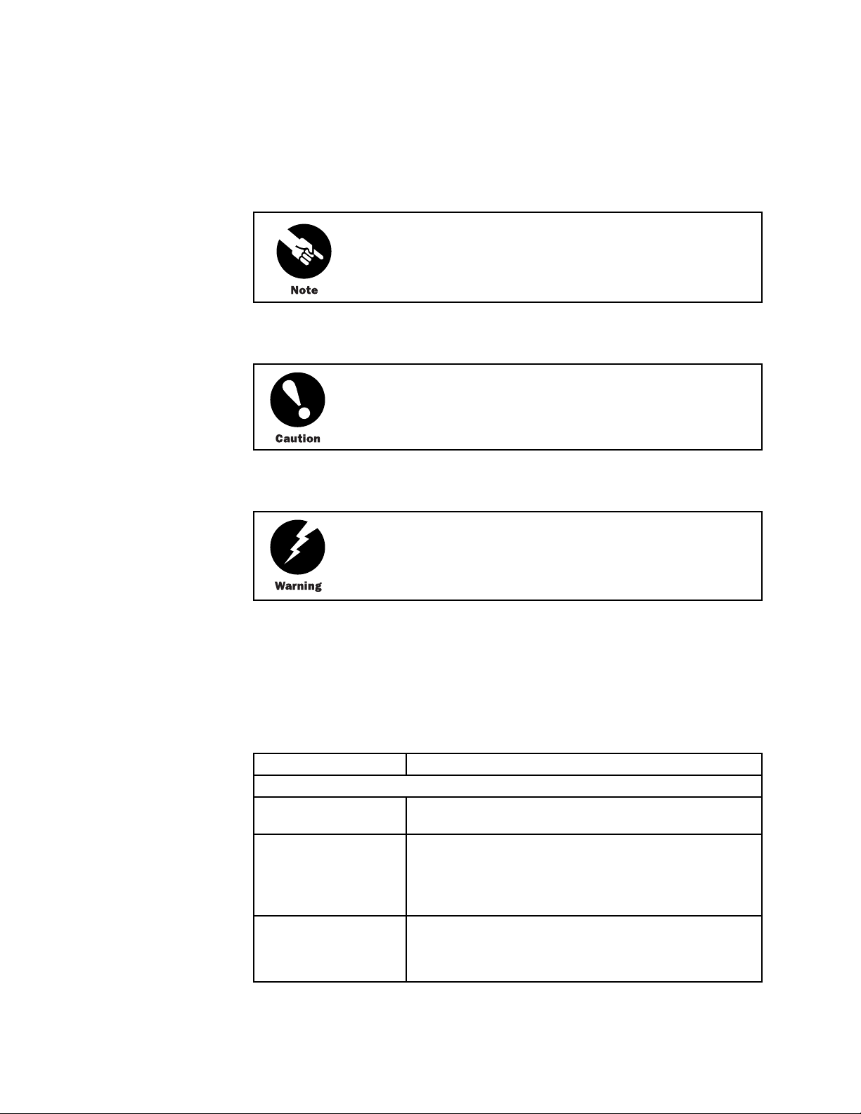
Figure 1, Figure 2, and Figure 3 show front and rear views of the router chassis.
Hardware Component Overview
5
Chassis
Figure 1: Front of M5 Chassis
PICs
1301
R
Mounting ear
Figure 2: Front of M10 Chassis
Mounting ear
Craft interface
Craft interface
PICs
ESD
point
1300
ESD
point
6 M5 and M10 Internet Routers Hardware Guide
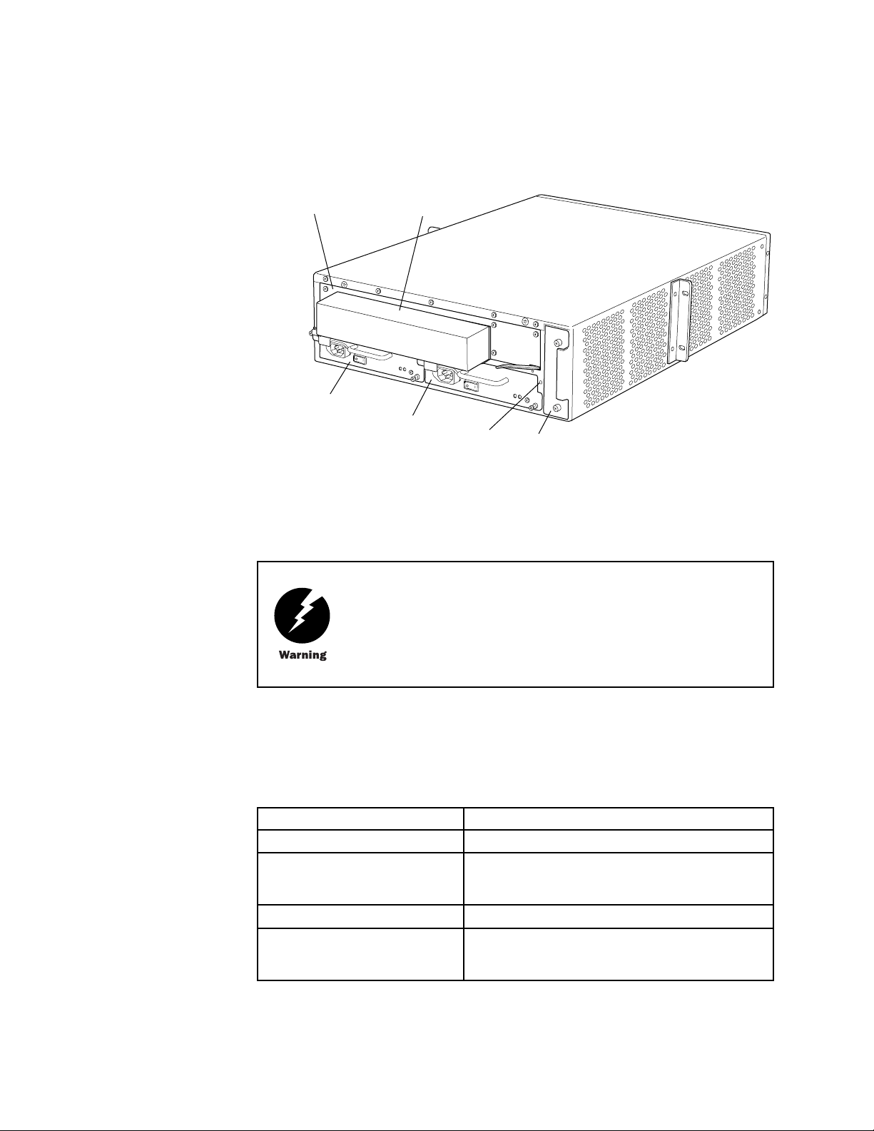
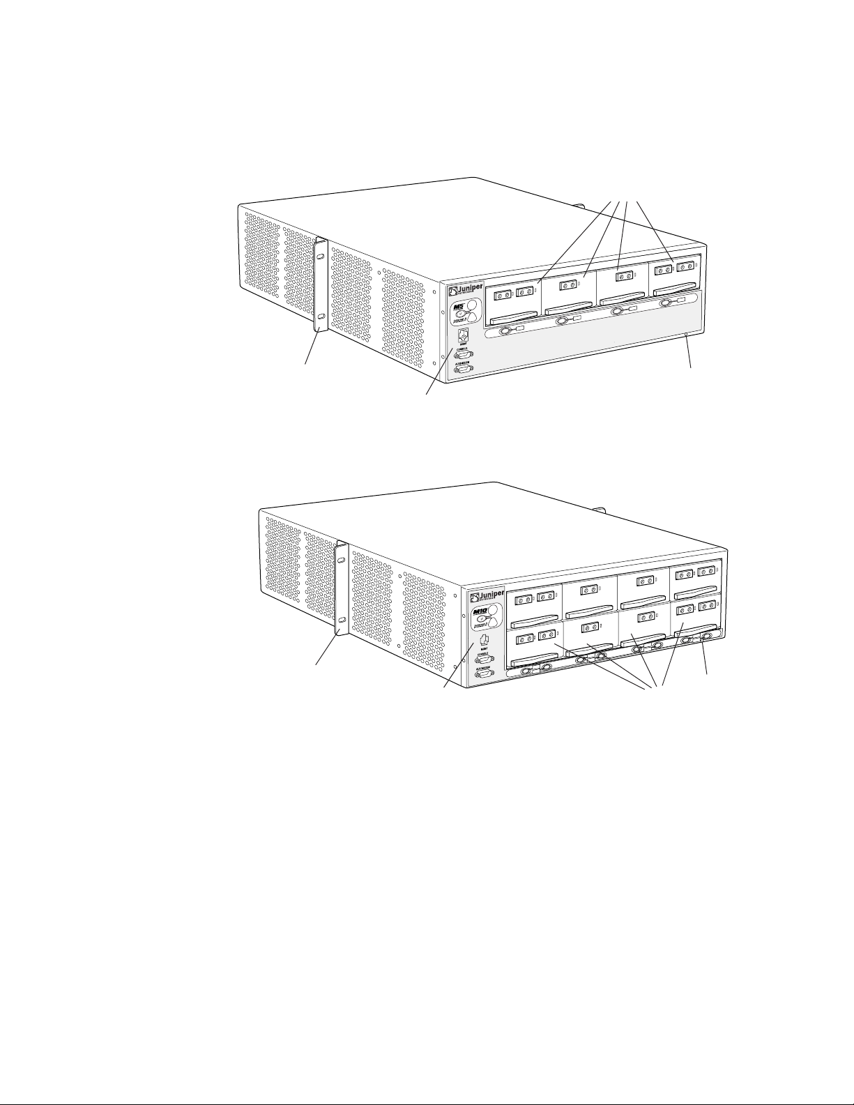
Figure 3: Rear of Chassis
Chassis
Forwarding Engine
Board
Routing Engine
cover
Power supply A
The chass
Power supply B
is includes two electrostatic discharge (ESD) points (banana plug receptacles) for
ESD
point
Fan tray
electrical safety, one front and one rear, as shown in Figure 1, Figure 2, and Figure 3.
Before removing or installing components of a functioning router, attach an
ESD strap to an ESD point and place the other end of the strap around your
bare wrist. Failure to use an ESD strap could result in damage to the router.
1302
Table 3 summarizes physical specifications for the router chassis.
Table 3: Chassis Physical Specifications
Description Value
Chassis height
Chassis width 17.5 in. (44.5 cm) for sides of chassis
Chassis depth
Weight, maximum configuration M5 router: 61 lb (27.6 kg)
The router must be connected to earth ground during normal operation.
For further safety information, see “Safety and Regulatory Compliance
Informat
ion” on page 129.
5.25 in. (13.3 cm)
19 in. (4
8.3 cm) with mounting ears
24 in. (61 cm)
M10router: 67lb(29.5kg)
Hardware Component Overview 7

Packet Forwardin
gEngine
Description Value
Weight, minimum configuration 57 lb (25.8 kg)
Thermal output 2550 BTU/hour
Packet Forwarding Engine
The Packet Forwarding Engine is a multicomponent system that uses application-specific
integrated circuits (ASICs) to perform Layer 2 and Layer 3 packet switching, route lookups,
and packet fo
Processor II ASIC, I/O Manager ASIC, and media-specific controller ASICs.
rwarding. The ASICs include the Distributed Buffer Manager ASIC, Internet
Midplane
The Packet F
orwardingEnginehasthefollowingcomponents:
• Midplane—Physically separates front and rear cavities inside the chassis, distributes
power from t
components, which plug into it.
• Physical In
as OC-12/STM-4, OC-48/STM-16, Ethernet, and channelized interfaces.
• Flexible PI
built in (cannot be removed from the chassis as on some other M-series platforms).
• Forwardin
installs into the midplane from the rear of the chassis.
For inform
ation about Packet Forwarding Engine components, see t he following sections:
he power supplies, and transfers packets and signals between router
terface Cards (PICs)—Physically connect the router to network media such
C Concentrators (FPCs)—House PICs. On the M5 and M10 routers, FPCs are
g Engine Board (FEB)—Performs route lookup, filtering, and switching. It
• Midplane on page 8
• Physical Interface Cards (PICs) on page 9
• Flexible PIC Concentrators (FPCs) on page 10
• Forwarding Engine Board (FEB) on page 10
The midplan
forming the rear of the PIC card cage (see Figure 4). All router components plug directly
into the midplane. The midplane contains an EEPROM that stores the serial number and
revision l
The midplane performs the following functions:
e is a panel located in the center of the chassis, running from side to side and
evel of the midplane.
• Transfer of packets—After being processed by a PIC, an incoming data packet crosses
themidplanetotheFEB.TheFEBperformsswitchingandforwardingfunctionsand
transfers
to the network.
outgoing packets back across the midplane to the P ICs for transmission
8 M5 and M10 Internet Routers Hardware Guide
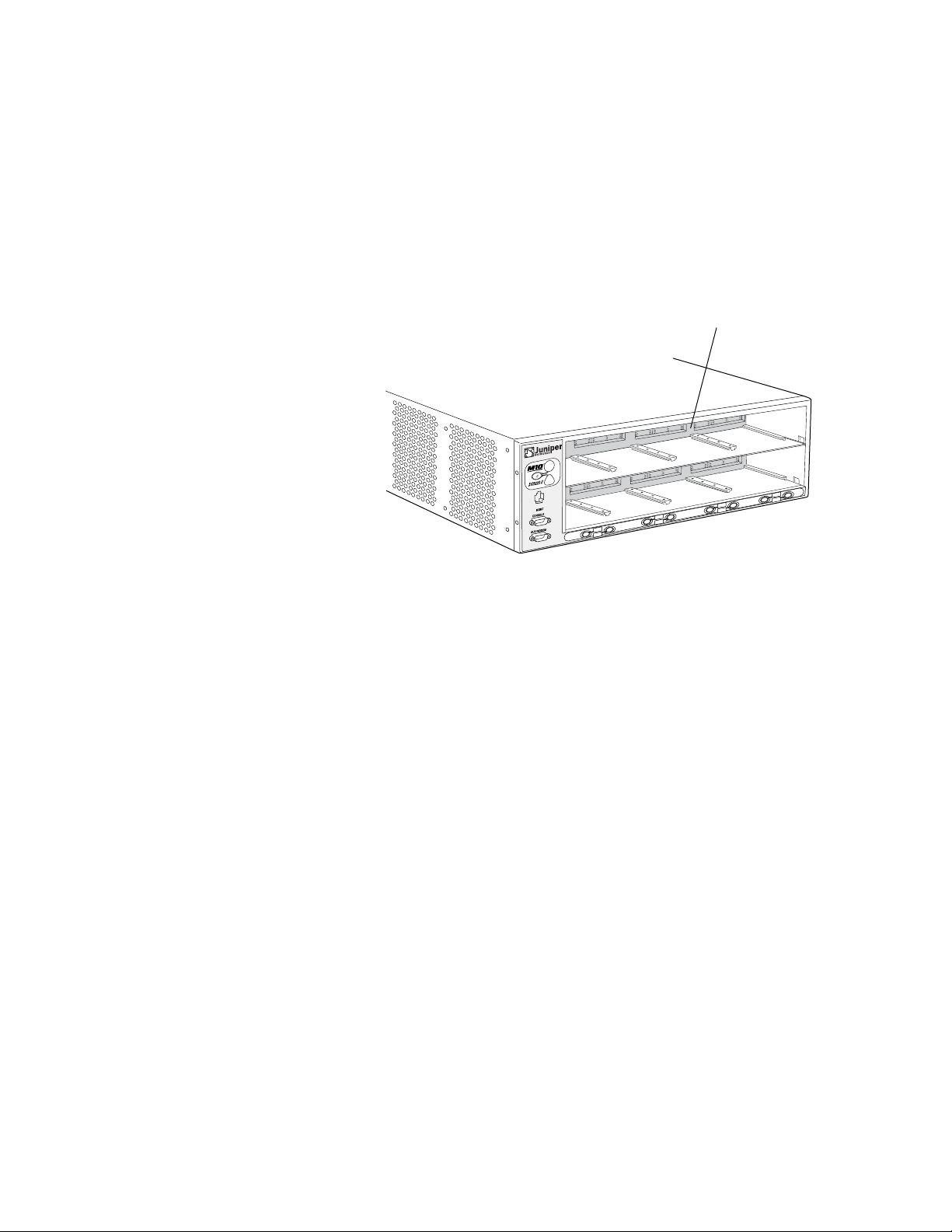
Figure 4: Midplane
Packet Forwardin
gEngine
• Power distribution—The midplane distributes power to all router components from the
power supplies attached to it.
• Signal connectivity—The midplane transports the signals exchanged by system
components for monitoring and control pur poses.
Midplane
1304
Physical Interface Cards (PICs)
Physical Interface Cards (PICs) physically connect the router to network media. They are
housed in Flexible PIC Concentrators (FPCs); for more information about FPCs, see “Fl exible
PIC Concentrators (FPCs)” on page 10.
PICsreceiveincomingpacketsfromthenetwork and transmit outgoing packets to the
network, performing framing and line-speed signaling for their media type as required.
PICs also encapsulate outgoing packets received from the FPCs before transmitting them.
The controller ASIC on each PIC performs additional control functions specific to the PIC
media type.
The router supports various PICs, including ATM, Channelized, Gigabit Ethernet, IP Services,
and SONET/SDH interfaces. For complete PIC specifications, see the M5 and M10 Internet
Routers PIC Guide.
Some PICs, such as selected Gigabit Ethernet PICs, accept small form factor pluggables (SFPs),
which are fiber-optic transceivers that can be removed from the PIC. Various SFPs have
different reach characteristics. You can mix them in a single PIC and change the combination
dynamically. SFPs are hot-removable and hot-insertable, as described in “Field-Replaceable
Units (FRUs)” on page 3. For SFP replacement instructions, see “Replace an S FP” on page
95. For information about PICs that use SFPs, see the M5 and M10 Internet Routers PIC Guide.
Up to four regular PICs install into an M5 router and up to eight regular PICs install into an
M10 router, as shown in Figure 1 and Figure 2. The PIC slots on an M5 router and in the upper
FPConanM10routerarenumberedfrom0/0 (zero/zero) through 0/3, right to left. The PIC
slots in the lower FPC on an M10 router are numbered from 1/0 (one/zero) through 1/3,right
to left. The slot number for a PIC appears next to its offline button on the craft interface (see
“PIC Offline Buttons” on page 16). The number of ports on a PIC depends on the type of PIC.
Hardware Component Overview
9

Packet Forwardin
gEngine
Quad-wide PICs, such as the 4-port Gigabit Ethernet and OC-48/STM-16 SONET/SDH PICs,
occupy all four slots in an FPC. Some quad-wide PICs might not be supported on both the M5
and M10 router
Both regular and quad-wide PICs are hot-removable and hot-insertable. A removed PIC
no longer rece
forwarding of traffic through the remaining PICs.
s; for more information, see the M5 and M10 Internet Routers PIC Guide.
ives or transmits data, and removing or inserting a PIC briefly interrupts
For PIC repla
PIC Components
Most PICs supported on the M5 and M10 routers have the following components. For
complete specifications, see the M5 and M10 Internet Routers PIC Guide.Forinformation
about pinouts for PIC cable connectors, see “Cable Connector Pinouts” on page 171.
cement instructions, see “Replace a PIC” on page 87.
• One or more cable connector ports—Accept a network media connector.
• LEDs—Indicate PIC and port status. Most PICs have an LED labeled STATUS on the
PIC faceplate. Some P ICs h ave additional LEDs, often one per port. The meaning of
the LED states differs for various PICs. For more information, see the M5 and M10
Internet Routers PIC Guide.
• Ejector lever—Controls the locking system that secures the PIC in the card cage.
Flexible PIC Concentrators (FPCs)
Flexible PIC Concentrators (FPCs) house the PICs that connect the router to network media
(for information about PICs, see “Physical Interface Cards (PICs)” on page 9). On the M5 and
M10 routers, each FPC is built in (cannot be removed from the chassis as on other M-series
platforms) and corresponds to a horizontal row of PIC slots. The single FPC on the M5 router
is numbered 0 (zero) and the two FPCs on the M10 router are numbered 0 and 1,topto
bottom. Each FPC accommodates up to fourregularPICsoronequad-widePIC.
Forwarding Engine Board (FEB)
The Forwarding Engine Board (FEB) performs route lookup, filtering, and switching
on incoming data packets, then directs outbound packets to the appropriate FPC for
transmission to the network. It can process 40 million packets per second (Mpps).
The FEB installs into the midplane from the rear of the chassis, as shown in Figure 3. It
weighs approximately 7 lb (3.2 kg). The FEB is field-replaceable, but you must power down
the router before removing it from the chassis. Packet forwarding halts until the FEB is
replaced, the router is powered on, and the Routing Engine finishes booting.
For FEB replacement instructions, see “Replace the FEB” on page 84.
The FEB communicates with the Routing Engine using a d edicated 100-Mbps Fast Ethernet
link that transfers routing table data from the Routing Engine to the forwarding table in the
Internet Processor II ASIC. The link is also used to transfer from the FEB to the Routing
10 M5 and M10 Internet Routers Hardware Guide

Packet Forwardin
Engine routing link-state updates and other packets destined for the router that have been
received through the router interfaces.
The ASICs and other components on the FEB provide the following functions:
gEngine
• Route lookups
using the forwarding table stored in SSRAM.
• Creation and r
into 64-byte data cells for easier processing, and reassembles the cells for each packet
after the forwarding decision is made for it. There is one I/O Manager ASIC on the
M5 router and
—The Internet Processor II ASIC on each FEB performs route lookups
eassembly of data cells—The I/O Manager ASIC divides incoming packets
two on the M10 router.
• Management of memory on the FEB—One Distributed Buffer Manager ASIC receives
the 64-byte d
uniformly allocates the cells throughout the memory buffers on the FEB.
• Transfer of o
notification of the forwarding decision for each packet to an I/O Manager ASIC so that
data cells for the outgoing packet can be reassembled for transmission to the network.
ata cells into which t he I/O M anager ASIC divides incoming packets, and
utgoing data packets—The second Distributed Buffer Manager ASIC passes
• Transfer of exception and control packets—The Internet Processor II ASIC passes
exception packets to the microprocessor on the FEB, which processes almost all of
them. The FE
further processing. When the FEB detects an error originating in the Packet Forwarding
Engine, it sends it to the Routing Engine using system logging (syslog) messages.
B sends any remaining exception packets to the Routing Engine for
• Monitoring of system components—The FEB monitors other system components for
failure and alarm conditions. It collects statistics from all sensors in the system and
relays the
the temperature of a component exceeds the lower of two internally defined thresholds,
the Routing Engine issues a “high temperature” alarm. If the temperature exceeds the
higher thr
m to the Routing Engine, which sets alarms as appropriate. For example, if
eshold, the Routing Engine initiates a system shutdown.
FEB Components
• Providing SONET/SDH clock source—The FEB generates a 19.44-MHz clock signal for
use by SON
An FEB has the following components (see Figure 5):
ET/SDH interfaces.
• I/O Manager ASIC (one on the M5 router and two on the M10 router)—Divide incoming
packets into 64-byte data cells for easier processing, and reassemble the cells for each
packet after the forwarding decision is made for it.
• Two Distributed Buffer Manager ASICs—Process incoming and outgoing packets: one
distributes data cells (which the I/O Manager ASIC derives from incoming packets) to
the memory buffers on the FEB, while the second forwards notification of routing
decisions to an I/O Manager ASIC.
• One Internet Processor II ASIC—Performs route lookups and makes routing decisions.
• Parity-protected synchronous SRAM (SSRAM)—Stores the forwarding table.
Hardware Component Overview
11

Routing Engine
• Processor subsystem—Manages FEB functions and handles exception packets. The
processor has the following components:
• OnePowerPC603eprocessor
• EEPROM—Stores the serial number and revision level.
• 19.44-MHz str
2
• I
C controller—Monitors the status of router components.
• Ejector levers—Control the locking system that secures the FEB in the chassis.
Figure 5: Forwarding Engine Board
• Parity-prote
cted Level 2 cache
• Parity-protected DRAM
atum 3 reference clock—Generates clock signal for SONET/SDH PICs.
For specific information about FEB components (for example, the amount of
DRAM), issue the show chassis feb command.
Routing Engine
The Routing Engine is an Intel-based PCI platform that runs JUNOS Internet software.
Software processes that run on the Routing Engine maintain the routing tables, manage the
routing protocols used on the router, control the router’s interfaces, control some chassis
components, and provide the interface for system management and user access to the router.
12 M5 and M10 Internet Routers Hardware Guide
1307

The Routing Engine installs into a slot in the FEB at the rear of the chassis. The Routing
Engine is field-replaceable, but you must power down the router before removing it from
the chassis. P
powered on. For replacement instructions, see “Replace the Routing Engine” on page 115.
acket forwarding halts until the Routing Engine is replaced and the router is
Routing Engine Components
The Routing Engine (shown in Figure 6) is a two-board system with the following components:
Routing Engine
• CPU—Runs JUN
protocols. It has a Pentium-class processor.
• SDRAM—Provi
Engine processes.
• Compact flas
and microcode. The drive is fixed and inaccessible from outside the router.
• Hard drive—P
the system if the flash drive fails.
• PC card slot
upgrades.
• LED—Indica
indicate routing-related activity.
• Interfaces
Routing Engine status to devices (console, laptop, or terminal server) that can be
attached to access ports located on the craft interface.
OS Internet software to maintain the router’s routing tables and routing
des storage for the routing and forwarding tables and for other Routing
h drive—Provides primary storage for software images, configuration files,
rovides secondary storage for log files, memory dumps, and rebooting
—Accepts a removable PC card, which stores software images for system
tes disk activity for the internal IDE interface. It does not necessarily
for out-of-band management access—Provide information about
• EEPROM—Stores t he serial number of the Routing Engine.
• Reset butt
on—Reboots the Routing Engine when pressed.
• Extractor clips—Control the locking system that secures the Routing Engine in the
chassis.
The appear
on your Routing Engine might differ from Figure 6 and other figures in this
document
Routing Engine installation and removal or functionality.
ance and position of electronic components or the PC card slot
that depict the Routing Engine. These differences do not affect
Hardware Component Overview 13

Craft Interface
For specific information about Routing Engine c om ponents (for example, the
capacity of th
Figure 6: Routing Engine
Routing Engine 333 Routing Engine 600
eharddrive),issuetheshow chassis routing-engine command.
Extractor clipExtractor clip
LED
PC card slot
Craft Interface
Figure 7: Craft Interface
Lamp test button
Link status LED
Routing Engine
ports
P
C
C
A
R
JUNIPER NETWORKS LABEL THIS SIDE
D
RESET
HD
PC card slot
Extractor clip
LED
Extractor clip
The craft interface provides status and troubleshooting information at a glance and has
buttons for deactivating alarms and preparing FPCs for removal. The L-shaped craft interface
is located along the left and bottom edges of thefrontofthechassis,asshowninFigure1
and Figure 2. It includes the elements shown in Figure 7. (The LEDs for the power supplies
are located on the power supply faceplate, rather than on the craft interface. For more
information, see “Power Supply LEDs and Self-test Button” on page 19.)
R
Red alarm LED
Yellow alarm LED
Activity status LED
1596
PIC0/3
PIC1/3
14 M5 and M10 Internet Routers Hardware Guide
PIC0/2
PIC1/2
PIC online/offline buttons
PIC0/1
PIC1/1
PIC0/0
PIC1/0
1336

Craft Interface
For information about the elements on the craft interface, see the following sections:
• Alarm LEDs and Lamp Test Button on page 15
• Routing Engine
Interface Ports and Status Indicators on page 15
• PIC Offline Buttons on page 16
AlarmLEDsandLampTestButton
Two large alarm LEDs are located at the top of the craft interface. The circular red LED lights
to indicate a critical condition that can result in a system shutdown. The triangular yellow
LED lights to indicate a less severe condition that requires monitoring or maintenance. Both
LEDs can be lit simultaneously. The button labeled LT (for “lamp test”), located to the left of
the alarm LEDs, causes all LE Ds on the c raft interface to light when pressed and held; use it
to test that LEDs are functional.
Table 4 describes the alarm LEDs and lamp test button in more detail.
Table 4: Alarm LEDs and Lamp Test Button
Shape Color State Description
Red On steadily Critical alarm LED—Indicates a critical condition
Yellow On steadily Warning alarm LED—Indicates a serious but
——
that can cause the router to stop functioning.
Possible causes include component removal,
failure, or overheating.
nonfatal error condition, such as a maintenance
alert or a significant increase in component
temperature.
Lamp test button—Causes all LEDs on the craft
interface t
pressed and held.
o light (for testing purposes), when
Routing Engine Interface Ports and Status Indicators
Below the alarm LEDs on the craft interface are ports for connecting the Routing Engine
to one or more external devices on which system administrators can issue JUNOS
command-line interface (CLI) commandstomanagetherouter(seeFigure7).Theportswith
the indicated label in each set function as follows:
• MGMT—Connects the Routing Engine through an Ethernet connection to a
management LAN (or any other device that plugs into an Ethernet connection) for
out-of-band management. The port uses an autosensing RJ-45 connector to support
both 10- and 100-Mbps connections.
Totheleftoftheportisalinkstatusindicator, which lights to show that a link has
been established over the Ethernet connection. To the r ight of the port is an activity
indicator, which flashes when data is being transferred.
Hardware Component Overview
15

Power Supplies
• CONSOLE—Connects the Routing Engine to a system console through an RS-232
(EIA-232) serial cable.
• AUX/MODEM— Connects the Routing Engine to a laptop, modem, or other auxiliary
device through an RS-232 (EIA-232) serial cable.
For information about the pinouts for the connectors, see “Cable Connector Pinouts”
on page 171.
PIC Offline B
uttons
Power Supplies
An offline button for each PIC is located below the PIC slot along the bottom edge of the
craft interf
when pressed. The buttons are labeled with the PIC slot numbers. The PIC slots on an M5
router and in the upper FPC on an M10 router are numbered from 0/0 (zero/zero) through
0/3,rightto
1/0 (one/zero) through 1/3,righttoleft.
The router uses either AC or DC power. There are two load-sharing, isolated power supplies
located at the bottom rear of the chassis, as shown in Figure 3. The power supplies
connect to
individual voltage requirements. When the power supplies are installed and operational, they
automatically share the electrical load. If a power supply stops functioning for any reason,
the remain
normal functioning and can provide full power indefinitely.
ace(seeFigure7). ThebuttonpreparesthePICforremovalfromtherouter
left. The PIC slots in the lower FPC on an M10 router are numbered from
the midplane, which distributes power to router components a ccording to their
ing power supplies instantly begin providing all the power the router needs for
Mixing AC and DC power supplies is not supported. The two power supplies
must be either both AC or both D C.
An enable control signal on the output connector of each power supply ensures that the
supply i
enable pin prevents a user-accessible energy hazard, so there is no interlocking mechanism.
The enable pin disables the voltage at the output connector if the power supply is not
turned
Power supplies are hot-removable and hot-insertable, as described in “Field-Replaceable
Units (
“Replace an AC Power Supply” on page 98 and “Replace a DC Power Supply” on page 104.
s fully seated into the router midplane before the supply can be turned on. The
off before removal.
FRUs)” on page 3. To avoid electrical injury, carefully follow the instructions in
16 M5 and M10 Internet Routers Hardware Guide

Power Supplies
After powering off a power supply, waitatleast60secondsbeforeturning
it back on. Afte
before turning it off.
If the router is completely powered down when you power on the power
supply, the Routing Engine boots as the power supply completes its startup
sequence. If the Routing Engine finishes booting and you need to power
down the router again, first issue the CLI request system halt command.
For more information, see “Disconnect AC Power f rom the Router” on page
102 or “Disconnect DC Power from the Router” on page 109.
After a power supply is powered on, it can take up to 60 seconds for
status indicators—such as LEDs on the power supply and show chassis
commands—to indicate that the power supply is functioning normally.
Ignore error indicators that appear during the first 60 seconds.
See the following sections for further information about power system components:
r powering on a power supply, wait at least 60 seconds
AC Power Supply
An AC-powered router has two load-sharing AC power supplies, located at the bottom rear of
the chassis, as shown in Figure 3. For information about power supply redundancy and
replaceabili
Figure 8 shows the power supply and Table 5 lists electrical specifications. For information
about the LED
Figure 8: AC Power Supply
• AC Power Suppl
y on page 17
• DC Power Supply on page 18
• Power Supply LEDs and Self-test Button on page 19
ty, see “Power Supplies” on page 16.
and self-test button, see “Power Supply LEDs and Self-test Button” on page 19.
Safety lever
1316
Appliance
inlet
Power switch
Self test
button
Status LED
Hardware Component Overview 17

Power Supplies
Table 5: Electrical Specifications for AC Power Supply
Description Specification
Maximum power output 800 W
AC input voltage Nominal range: 100–240 VAC
Operating range: 100–264 VAC
AC input line frequency
AC input curre
Output voltages
nt rating
47–63Hz
8–4A
+1.5 V, +2.5 V, +3.3 V, +5.0 V, + 12 V, +12 V
DC Power Supply
A DC-powered router has two load-sharing DC power supplies, located at the bottom rear of
the chassis, as shown in Figure 3. For information about power supply redundancy and
replaceability, see “Power S upplies” on page 16.
Figure 9 shows the power supply and Table 6 lists electrical specifications. For information
about the LED and self-test button, see “Power Supply LEDs and Self-test Button” on page 19.
Figure 9: DC Power Supply
terminals
Status LED
Table 6: Electrical Specifications for DC Power Supply
Description Specification
Maximum power output 700 W
DC input voltage Nominal: –48 VDC, –60 VDC
Self test
button
Power switchQuick connect
1320
Operating range: –42.5 to –72 VDC
18 M5 and M10 Internet Routers Hardware Guide

Fan Tray
Description Specificatio
Input DC current rating 13.5 A @ –48 V
Output voltages
The DC power supplies are marked –48 VDC. This is the nominal voltage
associated with the battery circuit. Any higher voltages are to be associated
only with float voltages for the charging function.
+1.5 V, +2.5 V, +3.3 V, +5.0 V, + 12 V, +12 V
Power Supply LEDs and Self-test Button
Table 7 describes the LED on both AC and DC power supplies.
Table 7: States for Power Supply LED
Label Color State Description
OUTPUT
OK
Blue
On steadily Power supply is functioning normally, input is
Blinking Power supply has failed.
n
occurring, outp uts are within range, and the
temperature is within range.
The self-test button on the power supply faceplate initiates a self-test sequence. Do not press
this button; it is for use by qualified service personnel only.
Fan Tray
The router cooling system c onsists of a fan tray that installs into the chassis from the rear, as
shown in Figure 3. It houses four fans, which draw room air into the chassis to keep the
internal temperature below a maximum acceptable level. The air flows side-to-side in the
chassis, as shown in Figure 10.
Figure 10: Airflow through the Chassis
Front of chassisFan tray
1305
Hardware Component Overview 19

Cable Management
System
The fan tray is hot-removable and hot-insertable, as described in “Field-Replaceable Units
(FRUs)” on page 3. For instructions on replacing it, see “Replace the Fan Tray” on page 82.
Do not remove the fan tray for more than a about one minute while the
router is operating. The fans are the solesourceofcooling,andtherouter
can overheat when they are absent.
Cable Manag
Figure 11: Cable Management System
ement System
The cable management system consists of racks that attach vertically to each side of the
chassis at t
racks to keep the cables organized and securely in place, and to avoid bending optical cables
beyond the proper bend radius. The cable management system evenly distributes the weight
of a cable,
he front, as shown in Figure 11. Pass PIC cables through the openings in the
so that it is not subjected to undue stress at the connector.
1341
Cable management
system
20 M5 and M10 Internet Routers Hardware Guide

Chapter 3
JUNOS Internet Software Overview
The JUNOS Internet software is especially designed for the large production networks typically
supported b
software and software for management of interfaces, networks, and the router chassis.
y Internet Service Providers (ISPs). It incorporates Internet Protocol (IP) routing
The JUNOS In
that support Internet routing protocols, control the router’s interfaces and the router chassis
itself, and provide an interface for system management. The processes run on top of a
kernel that
thePacketForwardingEnginesoftware.
Use the JUN
the properties of router interfaces. After you have activated a software configuration, use the
JUNOS Internet software to monitor the protocol traffic passing through the router and to
troublesh
For additional information about the JUNOS Internet software, includ ing its security features
and a list
Guide: Getting Started. For complete information about configuring the software, including
examples, see the JUNOS Internet software configuration guides.
This chapter discusses the following topics:
ternet software runs on the Routing Engine. The software consists of processes
coordinates the communication among processes and has a direct link to
OS Internet software to configure the routing protocols that run on the router and
oot protocol and network connectivity problems.
of the industry standards it su pports, see the JUNOS Internet Sof tware Configuration
• RoutingEngineSoftwareComponentsonpage21
• To o l s for
Accessing an d Configuring the Software on page 27
• Tools for Monitoring the Software on page 27
• Software Upgrades on page 28
Routing Engine Software Components
The Routing Engine software consists of several software processes that control router
functions and a kernel that coordinates communication among the processes, as described
in the fol
lowing sections:
• Routing Protocol Process on page 22
• VPNs on page 26
• Interface Process on page 26
• Chassis Process on page 26
JUNOS Internet Software Overview
21

Routing Engine So
ftware Components
• SNMP and MIB II Processes on page 26
• Management Process on page 27
Routing Protoc
• Routing Engine
Kernel on page 27
ol Process
The JUNOS software routing protocol process controls the routing protocols that run on the
router. The ro
routing messages. It consolidates the routing information learned from all routing protocols
into common routing tables. From this routing information, the routing protocol process
determines th
Routing Engine’s forwarding table. Finally, the routing protocol process implements the
routing policies you specify, which determine how routing information is transferred between
the routing p
This section discusses the following topics:
uting protocol process starts all configured routing protocols and handles all
e active routes to network destinations and installs these routes into the
rotocols and the routing table.
• IPv4 Routing Protocols on page 22
• IPv6 Routing Protocols on page 24
• Routing and Forwarding Tables on page 24
• Routing Polic
For complete information about routing concepts, see the JUNOS Internet software
configurati
on guides.
y on page 25
IPv4 Routing Protocols
The JUNOS Internet software implements full IP routing functionality, providing support for
IP version 4 (IPv4). The routing protocols are fully interoperable with existing IP routing
protocols and provide the scale and control necessary for the Internet core. The software
provides support for the following routing and traffic engineering protocols:
• Unicast routing protocols
• BGP—Border Gateway Protocol, version 4, is an Exterior Gateway Protocol (EGP)
that guarantees loop-free exchange of routing information between routing
domains (also called autonomous systems). BGP, in conjunction with JUNOS
routing policy, provides a system of administrative checks and balances that can
be used to implement peering and transit agreements.
• ICMP—Internet Control Message Protocol router discovery is a method that
hosts can use to discover the addresses of operational routers on a subnet.
• IS-IS—Intermediate System-to-Intermediate System is a link-state interior
gateway protocol (IGP) for IP networks that uses the shortest-path-first algorithm
(SPF algorithm, also called the Dijkstra algorithm) to determine routes.
22 M5 and M10 Internet Routers Hardware Guide

Routing Engine So
ftware Components
• OSPF—Open Shortest Path First, version 2, is an IGP developed for IP networks
by the Internet Engineering Task Force (IETF). OSPF is a link-state protocol that
makes routing
decisions based on the SPF algorithm.
• RIP—Routing Information Protocol, version 2, is an IGP for IP networks
based on the Be
dynamically routes packets between a subscriber and a service provider
without the subscriber having to configure BGP or to participate in the service
provider’s I
llman-Ford algorithm. RIP is a distance-vector protocol. RIP
GP discovery process.
• Multicast routing protocols
• DVMRP—Distance Vector Multicast Routing Protocol is a dense-mode
(flood-and-prune) multicast routing protocol.
• IGMP—Internet Group Management Protocol, versions 1 and 2, is used to
manage membership in multicast groups.
• MSDP—Multicast Source Discovery Protocol enables multiple PIM sparse mode
domains to be joined. A rendezvous point (RP) in a PIM sparse mode domain
has a peerin
multicast sources from other domains.
g relationship with an RP in another domain, thereby discovering
• PIM sparse m
multicast routing protocol used to route traffic to multicast groups that might
span wide-area and interdomain internetworks. In PIM sparse mode, routers
explicitl
protocol.
• SAP/SDP—S
handle conference session announcements.
• MPLS appli
cation protocols
ode and dense mode—Protocol-Independent Multicast is a
y join and leave multicast groups. PIM dense mode is a flood-and-prune
ession Announcement Protocol and Session Description Protocol
• LDP—Label Distribution Protocol provides a mechanism for distributing
labels in n
label-switched paths (LSPs) through a network by mapping network-layer
routing information directly to data-link layer switched paths. LSPs created by
LDP can al
ontraffic-engineered applications. LDP allows routers to establish
so traverse LSPs created by Resource Reservation Protocol (RSVP).
• MPLS—Multiprotocol Label Switching enables you to configure LSPs through a
network e
the network by directing it through particular paths, rather than relying on an
IGP’s least-cost algorithm to choose a path.
ither manually or dynamically. You can control how traffic traverses
• RSVP—Resource Reservation Protocol, version 1, provides a mechanism for
engineering network traffic patterns that is independent of the shortest path
determi
is designed to operate with current and future unicast and multicast routing
protocols. JUNOS RSVP software supports dynamic signaling for MPLS LSPs.
ned by a routing protocol. RSVP itself is not a routing protocol, but
JUNOS Internet Software Overview
23

Routing Engine So
IPv6 Routing Protocols
ftware Components
The JUNOS Inte
IP version 6 (IPv6). The routing protocols are fully interoperable with existing IP routing
protocols and provide the scale and control necessary for the Internet core. The software
provides supp
rnet software implements full IP routing functionality, providing support for
ort for the following unicast routing protocols:
• BGP—Border Gateway Protocol, version 4, is an EGP that guarantees loop-free exchange
of routing in
BGP, in conjunction with JUNOS routing policy, provides a system of administrative
checks and balances that can be used to implement peering and transit agreements.
formation between routing domains (also called autonomous systems).
• ICMP—Internet Control Message Protocol router discovery is a method that hosts can
use to discover the addresses of operational routers on a subnet.
• IS-IS—Intermediate System-to-Intermediate System is a link-state interior gateway
protocol (IGP) for IP networks that uses the shortest-path-first algorithm (SPF algorithm,
also called
the Dijkstra algorithm) to determine routes.
• OSPF—Open Shortest Path First, version 3 (OSPFv3), supports version 6 of the Internet
Protocol (I
Router (DR) election, area based topologies and the Shortest Path First (SPF) calculations
remain unchanged. Some differences exist either due to changes in protocol semantics
between IPv
Pv6). The fundamental mechanisms of OSPF such as flooding, Designated
4 and IPv6, or to handle the increased address size of IPv6.
• RIP—Routing Information Protocol, version 2, is an IGP for IP networks based on the
Bellman-F
packets between a subscriber and a service provider without the subscriber having to
configureBGPortoparticipateintheserviceprovider’sIGPdiscoveryprocess.
ord algorithm. RIP is a distance-vector protocol. RIP dynamically routes
Routing and Forwarding Tables
The primary function of the JUNOS routing protocol process is maintaining routing tables
and using the information in them to determine active routes to network destinations. It
copies information about the active routes into the Routing Engine’s forwarding table, which
the JUNOS kernel copies to the Packet Forwarding Engine.
By default, the routing protocol process maintains the following routing tables and uses the
information in each table to determine active routes to network destinations:
• Unicast routing table—Stores routing information for all unicast protocols running on
• Multicast routing table (cache)—Stores routing information for all multicast protocols
the router, including BGP, IS-IS, OSPF, and RIP. You can also configure additional routes,
such as static routes, for inclusion in the routing table. The unicast routing protocols use
the routes in this table when advertising routing information to their neighbors.
In the unicast routing table, the routing protocol process designates routes with the
lowest preference values as active. By default, a route’s preference value is simply a
function of how the routing protocol process learned about the route. You can modify
the default preference value by setting routing policies and configuring other software
parameters. See “Routing Policy” on page 25.
running on the router, including DVMRP and PIM. You can configure additional routes
for inclusion in the routing table.
24 M5 and M10 Internet Routers Hardware Guide

Routing Engine So
In the multicast routing table, the routing protocol process uses traffic flow and other
parameters specified by the multicast routing protocol algorithms to select active routes.
ftware Components
• MPLS routing table—Stores MPLS label information.
Routing Policy
For unicast ro
most preferred route, which is the route with the lowest preference value. By default, the
route’s preference value is simply a function of how the routing protocol process learned
about the rou
with software configuration parameters.
For multicas
flow and other parameters specif ied by the multicast routing protocol algorithms. The
routing protocol process then installs one or more active routes to each network destination
into the Rout
You can configure additional routing tables to meet your requirements, as described in the
JUNOS Inter
By default, all routing protocols place their routes into the routing table. When advertising
routes, the routing protocols, by default, advertise only a limited set of routes from the
routing table. Specifically, each routing protocol exports only the active routes that were
learned by that protocol. In addition, IGPs (IS-IS, OSPF, and RIP) export the direct (interface)
routes for the interfaces on which the protocol is explicitly configured.
For each routing table, you can affect the routes that a protocol places into the table and the
routes from the table that the protocol advertises by defining one or more routing policies
and then applying them to the specific routing protocol.
utes, the routing protocol process determines active routes by choosing the
te. You can modify the default preference value using routing policy and
t traffic, the routing protocol process determines active routes based on traffic
ing Engine’s forwarding table.
net Software Configuration Guide: Routing and Routing Protocols.
Routing policies applied when the routing protocol places routes into the routing table are
called import policies because the routes are being imported into the routing table. Policies
applied when the routing protocol is advertising routes that are in the routing table are called
export policies because the routes are being exported from the routing table. In other words,
the terms import and export are used with respect to the routing table.
Routing policy enables you to control (filter) which routes are imported into the routing table
and which routes are exported from the routing table. Routing policy also allows you to
set the information associated with a route as it is being imported into or exported from
the routing table. Routing policies applied to imported routes control the routes used to
determine active routes, whereas policies applied to exported routes control which routes a
protocol advertises to its neighbors.
You implement routing policy by defining policies. A policy specifies the conditions to use to
match a route and the action to perform on the route when a match occurs. For example,
when a routing table imports routing information from a routing protocol, a routing policy
might modify the route’s preference, mark the route with a c olor to identify it for later
manipulation, or prevent the route from even being installed in a routing table. When a
routing table exports routes to a routing protocol, a policy might assign metric values, modify
theBGPcommunityinformation,tagtheroutewith additional information, or prevent the
route from being exported altogether. You also can define policies for redistributing the
routes learned from one protocol into another protocol.
JUNOS Internet Software Overview
25

Routing Engine So
VPNs
ftware Components
Interface Process
The JUNOS soft
ware supports several types of VPNs:
• Layer 2 VPNs— A Layer 2 VPN links a set of sites sharing common routing information,
and whose conn
aware of routes within a customer’s network. It simply provides private links between a
customer’s sites over the service provider’s existing public Internet backbone.
ectivity is controlled by a collection of policies. A Layer 2 VPN is not
• Layer 3 VPNs—A Layer 3 VPN links a set of sites that share common routing
information, and whose connectivity is controlled by a collection of policies. A Layer 3
VPN is aware o
the part of the service provider than a Layer 2 VPN. The sites that make up a Layer 3
VPN are connected over a service provider’s existing public Internet backbone.
f routes within a customer’s network, requiring more configuration on
• Interprovider VPNs—An interprovider VPN supplies connectivity between two VPNs
in separate autonomous systems (ASs). This functionality could be used by a VPN
customer wi
same ISP in various geographic regions.
• Carrier-of
VPN service to a customer who is also a service provider. The latter service provider
supplies Internet or VPN service to an end customer.
The JUNOS interface process manages the physical interface devices and logical interfaces
on the router. It implements the JUNOS command-line interface (CLI) commands and
configura
location in the FPC card cage and PIC location on an FPC), the interface type (such as
SONET/SDH or ATM), encapsulation, and interface-specific properties. You can configure
both inter
tion statements that you use to specify interface properties such as location (FPC
faces that are currently active and interfaces that might be installed later.
th connections to several various ISPs, or different connections to the
-Carrier VPNs—Carrier-of-carrier VPNsallowaVPNserviceprovidertosupply
The JUNOS interface process communicates with the interface process in the Packet
Forwardi
the status and co ndition of router interfaces.
ng Engine through the JUNOS kernel, enabling the JUNOS Internet software to track
Chassis Process
The JUNOS chassis process allows you to configure and control the properties of the
router, including conditions that trigger alarms and clock sources. The chassis process
communic
ates directly with a chassis process in the JUNOS kernel.
SNMP and MIB II Processes
The JUNO
versions 1, 2, and 3, which provides a mechanism for monitoring the state of the router.
This software is controlled by the JUNOS SNMP and Management Information Base (MIB) II
process
S Internet software supports the Simple Network Management Protocol (SNMP),
es, which consist of an SNMP master agent and a MIB II agent.
26 M5 and M10 Internet Routers Hardware Guide

Management Process
Tools for Monitor
ing the Software
t process starts all the other JUNOS software processes and the CLI when
t also provides the link between the routing tables maintained by the routing
ng the Packet Forwarding Engine’s forwarding table with the master forwarding
Routing Engin
The managemen
the router boots. It monitors the running JUNOS processes and makes all reasonable
attempts to restart any process that terminates.
eKernel
The Routing Engine kernel provides the underlying infrastructure for all JUNOS software
processes. I
protocol process and the forwarding table maintained by the Routing Engine. Additionally, it
coordinates communication with the Packet Forwarding Engine, which primarily involves
synchronizi
table maintained by the Routing Engine.
Tools for Accessing and Configuring the Software
The JUNOS CLI is the primary tool for accessing and controlling the JUNOS Internet software.
You use it when accessing the router through the console or a connection to an out-of-band
management
JUNOS Internet software, and network connectivity.
The JUNOS C
and enter the commands by pressing the Enter key. The CLI provides command help and
command completion, as well as Emacs-style keyboard sequences for moving around on a
command li
For more information about the CLI, see the JUNOS Internet Software Configuration Guide:
Getting Started.
network. The CLI includes commands for configuring router hardware, the
LI is a straightforward command interface. You type commands on a single line
ne and scrolling through a buffer that contains recently executed commands.
Tools for
Monitoring the Software
In addition to commands for configuring router hardware and software, the CLI includes
commands
network connectivity. CLI commands display information from routing tables, information
specific to routing protocols, and information about network connectivity derived from
the ping
You can also use the JUNOS Internet software implementation of SNMP to monitor routers.
The SNMP
support for MIB II SNMP version 1 traps and version 2 notifications, SNMP version 1 Get and
GetNext requests, and version 2 GetBulk requests. For more information about SNMP, see
the JUNO
The software also supports tracing and logging operations, which you can use to track normal
router o
Logging operations use a syslog-like mechanism to record systemwide, high-level events such
as interfaces going up or down and user logins on the router. Tracing operations record more
detail
routing protocol packets sent and received, and routing policy actions.
for monitoring and troubleshooting hardware, software, routing protocols, and
and traceroute utilities.
software consists of an SNMP master agent and a MIB II agent. It provides full
S Internet Software Configuration Guide: Network Management.
perations, error conditions, and the packets that the router generates or forwards.
ed information about the operation of routing protocols, such as the various types of
JUNOS Internet Software Overview
27

Software Upgrade
s
Software Upgrades
The router is d
software, you use CLI commands to copy a set of software images over the network to
memory storage on the Routing Engine. The JUNOS Internet software set consists of several
images provid
simultaneously. For information about installing and upgrading JUNOS software, see the
JUNOS Internet Software Configuration Guide: Getting Started.
elivered with the JUNOS Internet software preinstalled. To upgrade the
ed in individual packages or as a bundle. You normally upgrade all packages
28 M5 and M10 Internet Routers Hardware Guide

Chapter 4
System Architecture Over view
The router architecture consists of two major components:
• Packet Forwarding Engine—Performs Layer 2 and Layer 3 packet switching, route
lookups, and packet forwarding.
• Routing Engine—Provides Layer 3 routing services and network management.
The Packet F
communicate constantly through a 100-Mbps internal link. This arrangement provides
streamlined forwarding and routing control and the ability to run Internet-scale networks at
high speeds
and the Routing Engine.
Figure 12: System Architecture
For a discussion of the architectural components, see the following sections:
• Packet Forwarding Engine Architecture on page 29
• Routing Engine Architecture on page 31
orwarding Engine and the Routing Engine perform independently but
. Figure 12 illustrates the relationship between the Packet Forwarding Engine
Routing Engine
100-Mbps link
Packets
in
Packet Forwarding
Engine
Packets
out
1244
Packet Forwarding Engine Architecture
The Packet Forwarding Engine performs Layer 2 and Layer 3 packet switching. It can forward
up to 40 for all packet sizes. The aggregate throughput for the router is 6.4 gigabits per second
(Gbps), full duplex. The Packet Forwarding Engine is implemented in application-specific
integrated circuits (ASICs). It uses a centralized route lookup engine and shared memory.
The Packet Forwarding Engine architecture includes the following components:
System Architecture Overview
29

Packet Forwardin
gEngineArchitecture
• Midplane—Transports packets, notifications, and other signals between the PICs and
the Packet Forwarding Engine (as well as other system components).
• Physical Interface C ard (PIC)—Physically connects the router to fiber-optic or digital
network media. A controller ASIC in each PIC performs control functions specific to
thePICmediat
ype.
• Forwarding Engine Board (FEB)—Hosts the Internet Processor II ASIC, I/O Manager
ASIC (one on t
Manager ASICs. An I/O Manager ASIC divides incoming packets into 64-byte data cells
and reassembles cells into data packets for transmission on the network after the
Internet Pro
Manager ASIC distributes the data cells among the memory buffers on the F EB and the
other notifies the PICs of the forwarding decision for outgoing packets.
he M5 router, two on the M10 router), and two Distributed Buffer
cessor II ASIC decides how to forward the packets. One Distributed Buffer
Data Flow through the Packet Forwarding Engine
Use of ASICs promotes efficient movement of data packets through the system. Packets flow
through the Packet Forwarding Engine in the following sequence (see Figure 13):
1. Packets arrive at an incoming PIC interface.
2. The PIC passes the packets through the midplane to the FEB.
3. An I/O Manager ASIC on the FEB processes the packet headers and divides the packets
into64-bytedatacells.
4. A Distributed Buffer Manager ASIC on the FEB distributes the data cells throughout the
memory bu
5. The Inter
and decides how to forward it.
6. The Internet Processor II ASIC notifies the second Distributed Buffer Manager ASIC
of the forwarding decision, and the Distributed Buffer Manager ASIC forwards the
notific
7. The I/O M
data packets as they are ready for transmission and passes them to the outbound PIC.
8. The outbound PIC transmits the data packets.
ffers on the FEB.
net Processor II ASIC on the FEB performs a route lookup for each packet
ation to the appropriate outbound PIC.
anager ASIC on the FEB reassembles data cells stored in shared memory into
30 M5 and M10 Internet Routers Hardware Guide

Figure 13: Packet Forwarding Engine Components and Data Flow
Routing Engine Ar
chitecture
Routing E
Packet
in
Packet
out
= ASIC
ngine Architecture
The Routing Engine is an Intel-based PCI platform running the JUNOS Internet software,
which Ju
interfaces and routes. The software consists of a set of system processes running in protected
memory modules on top of an independent operating system. The JUNOS kernel supports
JUNOS sy
and control functions (see Figure 14).
niper Networks has developed and optimized to handle large numbers of network
stem processes, which handle system management processes, routing protocols,
PIC
Controller
PIC
Controller
Midplane
I/O
Manager
FEB
Distributed
Buffer
Manager
Distributed
Buffer
Manager
Routing
Engine
Internet
Processor
II
1335
The Rout
Engine.
ing Engine has a dedicated 100-Mbps internal connection to the Packet Forwarding
System Architecture Overview
31

Routing Engine Ar
Figure 14: Routing Engine Architecture
chitecture
Routing En
JUNOS
software
gine Functions
The Routing Engine handles all routing protocol processes, as well as the software processes
that contr
access to the router. These routing and software processes run on top of a kernel that
interacts with the Packet Forwarding Engine. For more information about the processes,
see “Rout
The Routing Engine includes the following functions and features:
ol the router’s interfaces, the chassis components, system management, and user
ing Engine Software Components” on page 21.
• Processing of routing protocol packets—The Routing Engine han dles all packets that
concern routing protocols, freeing the Packet Forwarding Engine to handle only
packets t
System
management
processes
Intel-based PCI platform
hat represent Internet traffic.
Routing
protocols
Kernel
Control
functions
System processes
Operating system
1164
• Software modularity—Because each software process is devoted to a different
function
effect on the others.
• In-depth
set of Internet f eatures and provides full flexibility for advertising, filtering, and
modifying routes. Routing policies are set according to route parameters (for example,
prefix,
and uses a separate process space, the failure of one process has little or n o
Internet functionality—Each routing protocol is implemented with a complete
prefix lengths, and Border Gateway Protocol [BGP] attributes).
• Scalability—The JUNOS routing tables have been designed to hold all the routes in
current
software can efficiently support large numbers of interfaces and virtual circuits.
• Managem
including the JUNOS command-line interface (CLI), the JUNOScript application
programming interface, the craft interface, and SNMP.
networks with ample capacity for expansion. Additionally, the JUNOS Internet
ent interface—Different levels of system management tools are provided,
• Storage and change management—Configuration files, system images, and microcode
can be held and maintained in primary and secondary storage systems, permitting
rremoteupgrades.
local o
32 M5 and M10 Internet Routers Hardware Guide

• Monitoring efficiency and flexibility—The router supports func tions such as alarm
handling and packet counting on every port, without degrading packet-forwarding
performance.
The Routing Engine constructs and maintains one or more routing tables. From the routing
tables, the Ro
which is then copied into the Packet Forwarding Engine. The design of the ASICs allow
the forwarding table in the Packet Forwarding Engine to be updated without interrupting
forwarding p
Figure 15: Control Packet Handling for Routing and Forwarding Table Updates
uting Engine derives a table of active routes, called the forwarding table,
erformance. See Figure 15.
Routing protocol
process
Routing Engine Ar
chitecture
Forwarding table
updates
Packets
in
Routing Engine
Forwarding table
Packet Forwarding
Engines
Routing protocol
packets from network
Packets
out
1240
System Architecture Overview 33

Routing Engine Ar
chitecture
34 M5 and M10 Internet Routers Hardware Guide

Part 2
Initial Installation
• Prepare for Router Installation on page 37
• Unpack the Router on page 55
• Install the Router on page 59
• Connect the Router and Perform Initial Configuration on page 61
35

36 M5 and M10 Internet Routers Hardware Guide

Chapter 5
Prepare for Router Installation
This chapter describes how to prepare your site for installation of the M5 and M10 Internet
routers. It
• Rack Requirements on page 37
• Clearance Requirements for Airflow and Hardware Maintenance on page 40
• Router Environmental Tolerances on page 40
• Fire Safety Requirements on page 41
• Power Guidelines, Requirements, and Specifications on page 42
discusses the following topics:
• Network Cabl
• Cable Specifications for Routing Engine Management Interfaces on page 52
• Site Preparation Checklist on page 52
Rack Requirements
The router must be installed in a rack. Many types of racks are acceptable, including
front-mount racks, 4-post (telco) racks, and center-mount racks. An example of a
center-moun
The following sections describe rack requirements:
• Rack Size and Strength on page 37
• Spacing of Mounting Holes on page 39
• Connection to Building Structure on page 39
Rack Size and Strength
The router is designed for installation in a rack that complies with either of the following
standards:
• A 19-in. rack as defined in Cabinets, Racks, Panels, and Associated Equipment
(document number EIA-310-D) published by the Electronics Industry Association
(http://www.eia.org).
e Specifications and Guidelines on page 48
t rack appears in Figure 16.
Prepare for Router Installation
37

Rack Requirement
s
• A 600-mm rack as defined in the four-part Equipment Engineering (EE); European
telecommunications standard for equipment practice (document numbers ETS 300 119-1
through 119-4
(http://www.etsi.org).
) published by the European Telecommunications Standards Institute
The horizonta
are usually wider than the router’s mounting ears, which measure 19 in. (48.3 cm)
from outer edge to outer edge. Use approved wing devices to narrow the opening
between the r
The rack rails must be spaced widely enough to accommodate the router chassis’s external
dimensions:
outer edges of the mounting ears extend the width to 19 in. (48.3 cm). The spacing of rails
and adjacent racks must also allow for the clearances around the router and rack that are
specified i
In general, a center-mount rack is preferable to a front-mount rack, because the more even
distribu
rack is used, we recommend supporting the back of the router with a shelf or other structure.
The chass
Cabinets, Racks, Panels, and Associated Equipment (document number EIA-310-D) published
by the Electronics Industry Association. Youcanstack14M5andM10routersinarackthat
has at le
n “Clearance Requirements for Airflow and Hardware Maintenance” on page 40.
tion of weight in the center-mount rack provides greater stability. If a front-mount
is height of 5.25 in. (13.3 cm) equals 3 U, the standard rack unit defined i n
ast 42 U (73.5 in. or 1.87 m) of usable vertical space.
l spacing between the rails in a rack that complies with this standard
ails as required.
5.25 in. (13.3 cm) high, 24 in. (61 cm) deep, and 17.5 in. (44.5 cm) wide. The
The router
front-to-back position of the front mounting rails inside the cabinet.
If you mount the router in a cabinet, be sure that ventilation is sufficient to
prevent overheating.
might not fit into an 800-mm-deep cabinet, even if you adjust the
The rack must be strong enough to support the weight of the fully configured router, up to
about 61
routers in one rack, it must be capable of supporting about 940 lb (427 kg).
lb (27.6 kg) for the M5 router or 67 lb (29.5 kg) for the M10 router. If you stack 14
38 M5 and M10 Internet Routers Hardware Guide

Figure 16: Typical Center-Mount Rack
7 ft
(2.13 m)
19 in. (48.3 cm)
Rack Requirement
Mounting rails
s
Spacing of Mounting Holes
les in the mounting brackets are spaced at 2 U (3.5 in. or 8.89 cm), so the router can
The ho
be mounted in any rack that provides holes spaced at that distance.
Connection to Building Structure
Always secure the rack to the structure of the building. If your geographical area is subject
to earthquakes, bolt the rack to the floor. For maximum stability, also secure the rack to
ng brackets. For more information, see “Rack-Mounting Requirements and Warnings”
ceili
on page 147.
Floor bolts
1011
Prepare for Router Installation
39

Router Environme
ntal Tolerances
Clearance Requirements for Airflow and Hardware Maintenance
When planning
rack (see Figure 17):
• For the coolin
unrestricted. Allowing at least 6 in. ( 15.2 cm) o f clearance between each side of the
chassis and adjacent racks or equipment is recommended, particularly for routers in
which air flo
in the M5 and M10 routers.
• For service p
adequate space at the front and back of the router. Allow at least 24 in. (61 cm) in front
of the router and 19 in. (48.3 cm) behind it.
Figure 17: Chassis Dimensions and Clearance Requirements
Clearance required
the installation site, you need to allow sufficient clearance around the
g system to function properly, the airflow around the chassis must be
ws from side to side through the chassis. Figure 10 depicts the airflow
ersonnel to remove and install hardware components, there must be
for maintenance
17.5"
44.5 cm
24"
(61 cm)
6" (15.2 cm)
for airflow
19" (48.3 cm)24" (61 cm)
Clearance required
for maintenance
Rear of chassisFront of chassis
19"
(48.3 cm)
Router Environmental Tolerances
Table 8 specifies the environmental conditions required for normal router operation. In
addition, the site should be as dust-free as possible. Dust can clog air intake vents, reducing
cooling system efficiency. Check the vents frequently, cleaning them as necessary. For more
information, see “Maintain Hardware Components” o n page 75.
Table 8: Router Environmental Tolerances
Description Tolerance
Altitude No performance degradation to 10,000 ft (3048 m)
ve humidity
Relati
6" (15.2 cm)
Mounting ear
Normal
90%, noncondensing
operation ensured in relative humidity range of 5% to
1303
for airflow
40 M5 and M10 Internet Routers Hardware Guide

Description Tolerance
Temperature
Seismic
Fire Safety Requirements
Fire Safety Requi
Normal operation ensured in temperature range of 32° F to
104°F(0°Cto40°C)
Designed to meet Bellcore Zone 4 earthquake requirements
Install the router only in restricted areas, such as dedicated equipment
rooms and equipment closets, in accordance with Articles 110-16, 110-17,
and 110-18 of the National Electrical Code, A NSI/NFPA 70.
For additional safety guidelines and requirements, see “Safety and
Regulatory Compliance Information” on page 129.
rements
In the event
of people is the primary concern. You should establish procedures for protecting people in
the event of a fire emergency, provide safety training, and properly provision fire-control
equipment a
In addition, you should establish procedures to protect your equipment in the event of a fire
emergency
electronic equipment. We recommend that fire suppression equipment be available in the
event of a fire in the vicinity of the equipment, and that all local fire, safety, and electrical
codes and o
of a fire emergency involving routers and other network equipment, the safety
nd fire extinguishers.
. Juniper Networks products should be installed in an environment suitable for
rdinances be observed when installing and operating your equipment.
Fire Suppression
In the eve
the equipment at the source. Then use a Type C fire extinguisher, which uses noncorrosive
fire retardants, to extinguish the fire. For more information about fire extinguishers, see
“Fire Sup
nt of an electrical hazard or an electrical fire, you should first turn power off to
pression Equipment” on page 41.
Fire Suppression Equipment
Type C f ir
(CO2) and Halotron™, are most effective for suppressing electrical fires. Type C fire
extinguishers displace the oxygen from the point of combustion to eliminate the fire.
For exti
cooling, you should use this type of inert oxygen displacement extinguisher instead of an
extinguisher that leave residues on equipment.
e extinguishers, which use noncorrosive fire retardants such as carbon dioxide
nguishing fire on or around equipment that draws air from the environment for
Do not use multipurpose Type ABC chemical fire extinguishers (dry chemical fire
extinguishers) near Juniper Networks equipment. The primary ingredient in these fire
uishers is monoammonium phosphate, which is very sticky and difficult to clean.
exting
Prepare for Router Installation
41

Power Guidelines
, Requirements, and Specifications
In addition, in minute amounts of moisture, monoammonium pho sphate can become
highly corrosive and corrodes most metals.
Any equipment in a room in which a chemical fire extinguisher has been discharged
is subject to premature failure and unreliable operation. The equipment is considered to
be irreparabl
We recommend that you dispose of any irreparably damaged equipm ent in an
environme
y damaged.
To keep warranties effective, do not use a dry chemical fire extinguisher
to control a fire at or near a Juniper Networks router. If a dry chemical
fire extinguisher is used, the unit is no longer eligible for coverage under
a service agreement.
ntally responsible manner.
Power Guidelines, Requirements, and Specifications
The router
located at the bottom rear of the chassis, as shown in Figure 3. The power supplies
connect to the midplane, which distributes power to router components according to their
individu
automatically share the electrical load. If a power supply stops functioning for any reason,
the remaining power s upplies instantly begin providing all the power the router needs for
normal fu
For site wiring and power system guidelines, requirements, and specifications, see the
following sections:
uses either AC or DC power. There are two load-sharing, isolated power supplies
al voltage requirements. When the power supplies are installed and operational, they
nctioning and can provide full power indefinitely.
Mixing AC and DC power supplies is not supported. The two power supplies
must be e
ither both AC or both DC.
• Site Electrical Wiring Guidelines on page 43
• Router Power Requirements on page 43
• AC Grounding and Power Cord Specifications on page 45
• DC Groun
ding, Connection, and Cable Specifications on page 46
42 M5 and M10 Internet Routers Hardware Guide

Site Electrical Wiring Guidelines
Power Guidelines
, Requirements, and Specificatio ns
When planning
following sections.
Distance Limitations for Signaling
Improperly installed wires can emit radio interference. In addition, the potential for damage
from lightning strikes increases if wires exceed recommended distances, or if wires pass
between buildings. The electromagnetic pulse (EMP) caused by lightning can damage
unshielded conductors and destroy electronic devices. If your site has previously experienced
such problems, you might want to consult experts in electrical surge suppression and
shielding.
Radio Frequency Interference
You can reduc
site wiring by using twisted-pair c able with a good distribution of grounding conductors. If
you must exceed the recommended distances, use a high-quality twisted-pair cable with
one ground c
Electromagnetic Compatibility
If your site is susceptible to problems with electromagnetic compatibility (EMC), particularly
from lightning or radio transmitters, you might want to seek expert advice. Strong sources of
electromagnetic interference (EMI) can destroy the signal drivers and receivers in the router
and conduct power surges over the lines into the equipment, resulting in an electrical hazard.
It is particularly important to provide a properly grounded and shielded environment and to
use electrical surge-suppression devices.
the electrical wiring at your site, consider the factors discussed in the
e or eliminate the emission of radio frequency interference (RFI) from your
onductor for each data signal when applicable.
Router Power Requirements
Table 9 lists t he power requirements for various hardware components when the router is
operating under typical voltage conditions. For PIC power requirements, see the M5 and
M10 Internet Routers PIC Guide.
To comply with intrabuilding lightning/surge requirements, intrabuilding
wiringmustbeshielded,andtheshieldforthewiringmustbegrounded
at both ends.
Prepare for Router Installation
43

Power Guidelines
, Requirements, and Specifications
Table 9: Component Power Requirements
Component
Base system (all components except PICs,
with fans running at normal speed)
Fans running at full speed (additional power
Power Requirement
(Watts)
188 (approximate)
40 (approximate)
Power Requirement
(Amps)
4A/48V
(approximate)
0.833 A/48 V
required)
Routing Engine 17
FEB 50
0.2 A/48 V
1.1 A/48 V
You can use the information in Table 9 and the M5 and M10 Internet Routers PIC Guide to
calculate power consumption for various hardware configurations, input current from a
different s
ource voltage, and thermal output, as shown in the following examples. (For an
added safety margin, the examples use a generalized value for PICs of 0.625 A/48 V each.)
• Power consu
mption for minimum configuration:
Base system + 1 FEB + 1 Routing Engine + 1 PIC =
4A+1.1A++0
.2 A + 0.625 A = 5.925 A @ 48 V = 284 W DC
• Power consumption for maximum configuration (M5 router):
Base system + 1 FEB + 1 Routing Engine + 4 PICs =
4 A + 1.1 A + 0.2 A + 4(0.625 A) =
4A +1.1A +0.
2 A + 2.5 A = 9.6 A @ 48 V = 461 W DC
• Power consumption for maximum configuration (M10 router):
Base system + 1 FEB + 1 Routing Engine + 8 PICs =
4 A + 1.1 A + 0.2 A + 8(0.625 A) =
4A + 1.1A +0.
2 A + 5 A = 10.3 A @ 48 V = 494 W DC
• Input current from a DC source other than 48 V (based on maximally configured M10
router; app
• System ther
lies to DC power supply only):
(54 VDC input) x (input current X) = (48 VDC input) x (input current Y)
54 x X = 48 x 10
X = 48 x 10.3 A / 5 4 = 9.1 A
.3 A
mal output for maximally configured AC-powered M10 router:
Watts DC/85% AC PEM efficiency/0.293 = BTU/hr
494/0.85/0
.293 = 1984 BTU/hr
• System thermal output for maximally configured DC-powered M10 router:
Watts DC/0.293 = BTU/hr
494/0.293 = 1686 BTU/hr
44 M5 and M10 Internet Routers Hardware Guide

Power Guidelines
If you plan to operate a maximally configured DC-powered router, we
recommend that
circuit breaker rated for 20 A minimum. Doing so enables you to operate
the router in a
and allows the router to function at full capacity using one power supply.
If you plan to operate a DC- powered router at less than the maximum
configuration and do not provision a 20 A circuit breaker, we recommend
that you provision a circuit breaker rated for at least 125% of the continuous
current that the system draws at 48 V.
you provision at least 13.5 A @ 48 VDC and use a facility
ny configuration without upgrading the power infrastructure,
AC Grounding and Power Cord Specifications
To ground an AC-powered router, plug each power supply into a grounded AC power
receptacle. The receptacle provides the grounding for the router, so no additional grounding
is necessary. The receptacle must be within about 8 ft (2.5 m) of the router and must be
easily accessible.
, Requirements, and Specificatio ns
Detachable AC power cords, each 2.5 m (approximately 8 ft) long, are supplied with the
router. The appliance coupler at the female end of the cord inserts into the ap pliance inlet on
the faceplate of the AC power supply. The coupler is type C13 as described by International
Electrotechnical Commission (IEC) standard 60320. The plug at the male end of the power
cord fits into the power source receptacle that is standard for your geographical location.
Table 10 provides specifications and Figure 18 depicts the plug on the AC power cord
provided for each country or region.
Table 10: AC Power Cord Specifications
Country Electri
Australia
Europe (except Italy and United Kingdom)
Italy
Japan
North America
United Kingdom
In North America, AC power cords must not exceed 4.5 m (approximately
14.75 ft) in length, to comply with National Electrical Code (NEC) Sections
400-8 (NFPA 75, 5-2.2) and 210-52, and Canadian Electrical Code (CEC)
Section 4-010(3). The cords supplied with the router are in compliance.
cal Specification
240 VAC, 50 Hz AC
220 or 230 VAC, 50 Hz AC
230 VAC, 50 Hz AC
110VAC,50or60HzAC 498G
120 VAC, 60 Hz AC NEMA 5-15P
240 VAC, 50 Hz AC
Plug Typ
SAA/3
VII
I/3/16
BS89/3
e
Prepare for Router Installation 45

Power Guidelines
Figure 18: AC Plug Types
, Requirements, and Specifications
ItalyEurope UKAustralia
For information about the AC power supply, including electrical specifications and a
descriptio
connecting the power cord during initial installation, see “Connect Power to an AC-Powered
Router” on page 65. For instructions on replacing the power cord on an operating router, see
“Disconnec
n of components, see “AC Power Supply” on page 17. For instructions on
t and Connect AC Power” on page 101.
Power cords and cables must not block access to router components or
drape where people could trip on them.
Japan North America
DC Grounding, Connection, and Cable Specifications
To ground
it to one of the chassis grounding points on the upper rear edge of the chassis. To supply
power to the router, connect power cables to a separate, dedicated DC power source for
each pow
supply. Most sites distribute DC power through a main conduit that leads to frame-mounted
DC power distribution panels, one of which might be located at the top of the rack that
houses t
terminals to the power distribution panel.
a DC-powered router, connect a grounding cable to earth ground and then attach
er supply and attach the cables to the quick connect terminals o n each power
he router. A pair of cables (one input and one return) connects the quick connect
1013
1 sum marizes the specifications for the grounding and power cables, which you supply.
Ta b l e 1
Table 11: DC Power and Grounding Cable Specifications
Cable Type Quantity and Specification
Power
Grounding One 12-AWG (3.33 mm2) single-strand-count wire cable
-AWG (3.33 mm2) single-strand-count wire cables
Two 1 2
46 M5 and M10 Internet Routers Hardware Guide
Maximum
Equal
Length
None
None

Power Guidelines
For field-wiring c onnections, use copper conductors only.
For other electrical safety information, see “Electrical Safety Guidelines and
Warnings” on page 135.
Figure 19 shows how to attach the grounding and power cables. The grounding cable
attaches to o
accessory box shipped with the router contains the lug used to secure the grounding cable the
grounding point. The power cables insert into the quick connect terminals located on each
power suppl
ne of the grounding points on the upper edge of the router rear panel. The
y— the input terminal is labeled -48V and the return terminal is labeled RTN.
Before router installation begins, a licensed electrician must attach the cable
lug to the grounding cable that you supply. A cable with an incorrectly
attached lug can damage the router (for example, by causing a short circuit).
, Requirements, and Specificatio ns
Figure 19: DC Power and Grounding Cable Connections
-48V
RTN
Grounding
lug
Grounding
point
To ground
1331
For information about the DC power supply, including electrical specifica tions and a
description of compo nents, see “DC Power Supply” on page 18. For instructions on
Prepare for Router Installation
47

Network Cable Spe
cifications and Guidelines
connecting the DC power and grounding cables during initial installation, see “Connect
Power to a DC-Powered Router” on page 66. For instructions on replacing the cables on an
operating rou
ter, see “Disconnect and Connect DC Power” on page 108.
Power cords and cables must not block access to router components or
drape where people could trip on them.
Network Cable Specifications and Guidelines
The various
multimodeandsingle-modefiber-opticcable. Formoreinformation,seethefollowing
sections:
PICs supported on the router accept different kinds of network cable, including
• Fiber O p tic and Network Cable Specifications on page 48
• Signal Loss in Multimode and Single-Mode Fib er-Optic Cable on page 48
• Attenuation and Dispersion in Fiber-Optic Cable on page 49
• Calculatin
g Power Budget for Fiber-Optic Cable on page 49
• Calculating Power Margin for Fiber-Optic Cable on page 50
• Attenuate to Prevent Saturation at SONET/SDH PICs on page 51
Fiber Optic and Network Cable Specifications
The router supports PICs that use various kinds of network cable, including multimode and
single-mode fiber-optic cable. For information about the type of cable used by each PIC, see
the M5 and M1
0 Internet Routers PIC Guide.
Signal Loss in Multimode and Single-Mode Fiber-Optic Cable
Multimode
off the walls of the fiber). Interfaces with multimode optics typically use LEDs as light
sources. LEDs are not coherent sources, however . They spray varying wavelengths of light
into the mu
lines through a multimode fiber, causing signal dispersion. When light traveling in the fiber
core radiates into the fiber cladding, higher-order mode loss (HOL) results. Together these
factors l
fiber is large enough in diameter to allow rays of light to reflect internally (bounce
ltimode fiber, which reflects the light at different angles. Light rays travel in jagged
imit the transmission distance of multimode fiber compared to single-mode fiber.
Single-mode fiber is so small in diameter t hat rays of light can reflect internally through one
layer onl
single wavelength of light, which travels in a straight line through the single-mode fiber.
y. Interfaces with single-mode optics use lasers as light sources. Lasers generate a
48 M5 and M10 Internet Routers Hardware Guide

Network Cable Spe
Compared with multimode fiber, single-mode fiber has higher bandwidth and can carry
signals for longer distances. It is consequently more expensive.
For information about the maximum transmission distance and supported wavelength
rangeforthetypesofsingle-modeandmultimodefiber-opticcableusedbyPICson
theM5andM10r
the maximum transmission distances can result in significant signal loss, which c auses
unreliable transmission.
The router uses optical lasers for SONET/SDH PIC single-mode interfaces. These optics
comply with IR-1 of Bellcore GR-253-CORE Issue 2, December 1995 and ANSI TI.105.06.
outers, see the M5 and M10 Internet Routers PIC Guide. Exceeding
cifications and Guidelines
Attenuation
and Dispersion in Fiber-Optic Cable
Correct functioning of an optical data link depends on modulated light reaching the receiver
with enough p
light signal as it is transmitted. Attenuation is caused by passive media components, such as
cables, cable splices, and connectors. While attenuation is significantly lower for optical fiber
than for oth
efficient optical data link must have enough light available to overcome attenuation.
Dispersion
can affect an optical data link:
• Chromatic
speeds of light rays.
• Modal disp
propagation modes in the fiber.
For multim
attenuation, usually limits the maximum bit rate and link length. For single-mode
transmission, modal dispersion is not a factor. However, at higher bit rates and over longer
distance
An efficient optical data link must have enough light to exceed the minimum power that the
receiver
be less than the lim its specified for the type of link in Telcordia Technologies document
GR-253-CORE(Section4.3)andInternational Telecommunications Union (ITU) document
G.957.
ower to be demodulated correctly. Attenuation is the reduction in power of the
er media, it still occurs in both multimode and single-mode transmission. An
is the spreading of the signal in time. The following two types of dispersion
dispersion—The spreading of the signal in time resulting from the different
ersion—The spreading of the signal in time resulting from the different
ode transmission, modal dispersion, rather than chromatic dispersion or
s, chromatic dispersion rather than modal dispersion limits maximum link length.
requires to operate within its specifications. In addition, the total dispersion must
When chromatic dispersion is at the maximum allowed, its effect can be considered as a
power pe
component attenuation, power penalties (including those from dispersion), and a safety
margin for unexpected losses. For more information about power budget, see “Calculating
Power Bu
nalty in the power budget. The optical power budget must allow for the sum of
dget for Fiber-Optic Cable” on page 49.
Calculating Power Budget for Fiber-Optic Cable
To ensur
to calculate the link’s power budget, which is the maximum amount of power it can transmit.
e that fiber-optic connections have sufficient power for correct operation, you need
Prepare for Router Installation
49

Network Cable Spe
cifications and Guidelines
When you calculate the power budget, you use a worst-case analysis to provide a margin of
error, even though all the parts of an actual system do not operate at the worst-case levels. To
calculate the
power (PT) and minimum receiver sensitivity (PR):
worst-case estimate of power budget (PB), you assume minimum transmitter
PB=PT–P
The following hypothetic a l power budget equation uses values measured in decibels (dB) and
decibels ref
PB=PT–P
PB= –15 dBm – (–28 dBm)
PB=13dB
R
erred to one milliwatt (dBm):
R
Calculating Power Margin for Fiber-Optic Cable
After calcul
Budget for Fiber-Optic Cable” on page 49), you can calculate the power margin (PM), which
represents the amount of power available af ter sub tracting attenuation or link loss (LL)from
the power bu
PM=PB–LL
A PMgreater than zero indicates that the power budget is sufficient to operate the receiver.
Factors tha
dispersion, connectors, splices, and fiber attenuation. Table 12 lists an estimated amount of
loss for the factors used in the following sample calculations. For information about the actual
amount of si
ating a link’s power b udget (using the equation described in “Calculating Power
dget (PB). A worst-case estimate of PMassumes maximum LL:
t can cause link loss include higher-order mode losses, modal and chromatic
gnal loss caused by equipment and other factors, refer to vendor documentation.
Table 12: Estimated Values for Factors Causing Link Loss
Link-Loss Factor Estimated Link-Loss Value
Higher-order mode losses Single-mode—None
Modal and chromatic dispersion Single-mode—None
Connector
Splice 0.5 dB
Fiber attenuation Single-mode—0.5 dB/km
50 M5 and M10 Internet Routers Hardware Guide
Multimode—0.5 dB
Multimode—None, if product of bandwidth and
distance is less than 500 MHz–km
0.5 dB
Multimode
—1 dB/km

Network Cable Spe
The following example uses the estimated values in Table 12 to calculate link loss (LL)fora
2 km-long multimode link with a power budget (PB)of13dB:
cifications and Guidelines
• Fiber attenuation for 2 km @ 1.0 dB/km= 2 dB
• Loss for five c
onnectors @ 0.5 dB per connector = 5(0.5 dB) = 2.5 dB
• Loss for two splices @ 0.5 dB per splice =2(0.5 dB) = 1 dB
• Higher-order loss = 0.5 dB
• Clock recover
The power margin (PM) is calculated as follows:
PM=PB–LL
PM=13dB–2km(
PM=13dB–2dB–2.5dB–1dB–0.5dB–1dB
PM=6dB
The following
of 13 dB uses the estimated values from Table 12 to calculate link loss (LL)asthesumof
fiber attenuation (8 km @ 0.5 dB/km, or 4 dB) and loss for seven connectors (0.5 dB per
connector, o
PM=PB–LL
PM=13dB–8km(0.5dB/km)–7(0.5dB)
y module = 1 dB
1.0 dB/km) – 5 (0.5 dB) – 2 (0.5 dB) – 0.5 dB [HOL] – 1 dB [CRM]
sample calculation for an 8 km-long single-mode link with a power budget (PB)
r3.5dB).Thepowermargin(PM)iscalculatedasfollows:
PM=13dB–4dB
PM=5.5dB
In both examples, the calculated power margin is greater than zero, indicating that the link
has sufficient power for transmission and does not exceed the maximum receiver input
power.
–3.5dB
Attenuate to Prevent Saturation at SONET/SDH PICs
SONET/SDH i
(IR), and long reach (LR)— generate different output power levels and tolerate different input
power levels. Interfaces that h ave a longer reach can transmit enough power to saturate
the receive
PICs, and both IR and LR interfaces can saturate SR PICs. Interfaces in the same reach class
can also potentially saturate one another.
To prevent saturation, you might need to attenuate power at the PIC receiver, particularly if
you know that it has a shorter reach than the interface that is sending the signal. Determine
the amount
nterfaces in the different reach classes—short reach (SR), intermediate reach
rs on PICs that have a shorter reach. Specifically, LR interfaces can saturate IR
of attenuation needed by measuring the power level at each receiver. Attenuate
Prepare for Router Installation
51

Site Preparation
Checklist
the power to bring it within the allowable range; for short lengths of fiber, with fiber and
connector loss close to zero, an attenuator of 5 to 10 dB should be sufficient.
For specifications of minimum and maximum input level (receiver sensitivity and receiver
saturation) and minimum and maximum output level (average launch power) for the
SONET/SDH PIC
s supported on the M5 and M10 routers, see the M5 and M10 Internet
Routers PIC Guide.
Cable Specifications for Routing Engine Management Interfaces
For managem ent and service operations, you connect the Routing Engine to an external
console or management network through ports on the craft interface. For information about
the ports, se
Table 13 lists the specifications for the cables that connect to management ports.
e “Routing Engine Interface Ports and Status Indicators” on page 15.
Table 13: Cable Specifications for Routing Engine Management Interfaces
Port
Routing Engine
console or
auxiliary
interface
Routing Engine
Ethernet
interface
Cable
Specification
RS-232 (EIA-232)
serial
Category 5
cable
or equivalent
suitable f
or
100BaseT
Cable/Wire
Supplied
One 6-ft (1.83-m)
length with
DB-9/DB-9
connectors
One 15-ft (
4.57-m)
length with
RJ-45/RJ-
45
connectors
operation
Site Preparation Checklist
The checkl
forrouterinstallation.
Table 14: Site Preparation Checklist
Item or Task
Verify t
as temperature and humidity do not
exceed r
Environmental Tolerances” on page 40).
Measure distance between external power
sources and router installation site.
ist in Table 14 summarizes the tasks you need to perform w hen preparing a site
Performed
By Date Notes
hat environmental factors such
outer tolerances (see “Router
Maximum
Length
Router
Receptacle
6 ft (1.83 m) DB-9 male
RJ-45
328 ft (100
m)
autosensing
52 M5 and M10 Internet Routers Hardware Guide

Site Preparation
Checklist
Item or Task
Select the type of rack.
Plan rack location, including required space
clearances.
Secure rack to floor and building structure.
Acquire cables and connectors.
Locate sites for connection of system
grounding.
Calculate power budget and power margin.
Performed
By Date Notes
Prepare for Router Installation 53

Site Preparation
Checklist
54 M5 and M10 Internet Routers Hardware Guide

Chapter 6
Unpack the Router
This chapter explains how to unpack the router and verify the parts received. Before
beginning,
on page 37 and review the safety information in “Safety and Regulatory Compliance
Information” on page 129, especially “General Safety Guidelines and Warnings” on page 131
and “Instal
following topics:
• Tools Required on page 55
prepare the installation site as described in “Prepare for Router Installation”
lation Safety Guidelines and Warnings” on page 146. This chapter discusses the
Tools Required
Unpack the Router
• Unpack the R
outer on page 55
• Choose Front or Center Mounting on page 57
To unpack the router and prepare for installation, you need the following tools:
• Utility knife for cutting the sealing tape on the shipping carton
• Phillips (+) screwdriver, to move the mounting brackets and install the support shelf
if front-mounting the router
The router is shipped in a cardboard carton, held in place with foam packing material.
The crate also contains an accessory box, the front-mounting shelf, and the M5 and M10
Internet Router Installation Quick Start poster.
The router is maximally protected inside the shipping carton. Do not unpack
it until you are ready to begin installation.
To unpack the router, perform these steps:
1. Move the shipping carton to a staging area as close to the installation site as possible.
Unpack the Router
55

Unpack the Router
2. Position the carton so that the arrows are pointing up.
3. Using a utility knife, cut through the sealing tape on the top seam of the carton.
Open the top flaps of the carton.
4. Remove the accessory box and packing material from the top of the router.
5. Open the accessory box and verify the contents against the parts inventory on the label
attached to t
he box.
6. Remove the r
7. Verify the c
8. Save the shipping carton, packing materials, and pallet in case you later need to
Figure 20: Unpack the Router
outer from the shipping carton.
hassis components received against the packing list included with the router.
A generic parts inventory appears in Table 15.
move or ship the router.
Accessory box
Packing material
Router
Shipping carton
Table 15: Generic Inventory of Router Components
onent
Comp
Fan tray 1
FEB 1
56 M5 and M10 Internet Routers Hardware Guide
Quan
1339
tity

Component Quantity
Front-mounting shelf
Mounting ears 2
PIC and PIC blank
Power supply
Routing Engine 1
Choose Front or Center Mounting
You can mount t he router into either a center-mount rack, or into front-mount rack, four-post
rack, or cabinet. In general, a center-mount rack is preferable, because the more even
distribution of weight in the center-mount rack provides greater stability. If installing the
router in a front-mount rack, four-post rack, or cabinet, use the shelf that is provided in
theshippingcartontosupporttherouter.Before router installation, attach the shelf to the
back of the support posts in a front-mount rack, or to the front side of the rear posts
in a four-post rack or cabinet .
Choose Front or Ce
1
Upto4onanM5r
Upto8onanM10router
2
outer
nter Mounting
The router is shipped with the mounting ears installed in the center-mounting position,
asshowninFigure1andFigure2. Ifyouarefront-mountingtherouter,useaPhillips
screwdriver to remove the mounting ears from the center-mounting position. Remove the
screws from the two holes on each side of the chassis that are approximately 1.5 in. (3.8 cm)
back from the router faceplate. Install the mounting ears into those holes. If front-mounting
the router, also install the support shelf into therackbeforeinstallingthechassis. Attachthe
shelf to the rear of the rack’s front posts.
Unpack the Router
57

Choose Front or Ce
nter Mounting
58 M5 and M10 Internet Routers Hardware Guide

Chapter 7
Install the Router
Because the router weighs between 57 lb (25.8 kg) and about 61 lb (27.6 kg) for the M5 router
or 67 lb (29.
If you do not use a mechanical lift, installing the chassis safely requires two people to lift
and an addit
This chapter has the following sections:
• Tools and Parts Required on page 59
• Install the Chassis into the Rack on page 59
Tools and Parts Required
5 kg) for the M10 router, using a mechanical lift to install it is recommended.
ional person to insert the mounting screws.
To instal l t
parts:
• Mechanical
he chassis into a rack using a mechanical lift, you need the following tools and
lift (recommended)
• Phillips (+) screwdrivers, numbers 1 and 2
Install the Chassis into the Rack
Using a mechanical lift to maneuver the router into the rack is recommended because of the
router’s size and weight. The lift must be able to accommodate the router’s weight—between
57 lb (25.8
router depending on configuration—and must fit between the support posts of the rack.
First, p
kg) and about 61 lb (27.6 kg) for the M5 router or 67 lb (29.5 kg) for the M10
If you are installing multiple routers in one rack, install the lowest one first
and proceed upward in the rack.
erform the following prerequisite procedures:
• Verify that the router site meets the requirements described in “Prepare for Router
ation” on page 37.
Install
Install the Router
59

Install the Chass
is into the Rack
• Place the rack in its permanent location, allowing adequate clearance for airflow
• Read the information in “Installation Safety Guidelines and Warnings” on page 146,
• Remove the router from the shipping carton, as described in “Unpack the Router”
Then, perform the following procedures to install the router:
1. If you are front-mounting the router, move the mounting ears on the chassis from the
and maintenance, and secure it to the building structure. For details, see “Rack
Requirements
with particul
on page 55.
center-mounting position to the front-mounting position, and install the support shelf.
For instruct
” on page 37.
ar attention to “Chassis Lifting Guidelines” on page 146.
ions, see “Choose Front or Center Mounting” on page 57.
2. Position th
• If using a me
• If not using
3. Align the bottom hole in both mounting ears with a hole in each rack rail, making
sure the chassis is level.
4. Install one o f the mounting screws provided (in the accessory box shipped with the
router) i
screws.
5. Install a mounting screw into the top hole in each mounting ear.
6. Verify that the router is level.
7. If using a mechanical lift, move it away from the rack.
8. To continue the installation, proceed to “Con nect the Router and Perform Initial
Configuration” on page 61.
e chassis at the appropriate height in the rack:
chanical lift, load the router onto the lift, making sure it rests securely
on the lift platform. Use the lift to raise the chassis to the correct height.
a mechanical lift, have one person stand behind the router and another
person in front. Grasp the chassis, lift it, and position it at the correct height. Have
athirdpersonreadytoinstallthemountingscrews.
nto each of the two aligned holes. Use a Phillips screwdriver to tighten the
60 M5 and M10 Internet Routers Hardware Guide

Chapter 8
Connect the Router and Perform Initial Configuration
After installing the router into the rack as described in “Initial I nstallation” on page 35,
complete th
cables. This chapter has the following sections:
• Tools and Parts Required on page 61
e installation by connecting management and alarm devices, PICs, and power
• Connect the
Router to Management Devices on page 61
• Connect PIC Cables on page 63
• Provide Power to the Router on page 65
• Configure the JUNOS Internet Software on page 69
Tools and Parts Required
To connect the router to management devices and PICs and to power on the router, you
need the following tools and parts:
• Phillips (+) screwdrivers, numbers 1 and 2
• Flat-blade(-)screwdrivers,2.5mmand3mm
• Electrostatic damage (ESD) grounding wrist strap
Connect the Router to Management Devices
After you have installed the router into the rack, attach one or more external devices to
the ports on the craft interface that connect to the Routing Engine for management and
service operations (see Figure 21). For specifications for the cable accepted by the Routing
Engine management ports, see “Cable Specifications for Routing Engine Management
Interfaces” on page 52.
Connect the Router and Perform Initial Configuration
61

Connect the Route
r to Management Devices
Figure 21: Routing Engine Management Ports
R
Red alarm LED
Lamp test button
Yellow alarm LED
Link status LED
Routing Engine
Activity status LED
ports
PIC0/3
PIC1/3
PIC0/2
PIC1/2
PIC online/offline buttons
To connect external devices to the Routing Engine management ports, perform the
procedures described in the following sections:
• Connect to a Network for Out-of-Band Management on page 62
• Connect to a Management Console or Auxiliary Device on page 63
Connect to a Network for Out-of-Band Management
To connect
Ethernet cable with RJ-45/RJ-45 co nnectors to the MGMT port on the craft interface. One
such cable is provided with the router. For cable specifications, see “Cable Specifications for
Routing En
1. Turn off the power to the management device.
2. Plug one end of the Ethernet cable (Figure 22 shows the connector) into the MGMT port
3. Plug the o
the Routing Engine to a network for out-of-band management, connect an
gine Management Interfaces” on page 52. Follow this procedure:
on the cra
ftinterface(seeFigure21).
ther end of the cable into the network device.
PIC0/1
PIC1/1
PIC0/0
PIC1/0
1336
62 M5 and M10 Internet Routers Hardware Guide

Figure 22: Routing Engine Ethernet Cable Connector
Connect to a Management Console or Auxiliary Device
Connect PIC Cable
1063
s
To use a sys
CONSOLE port on the craft interface. To use a laptop, modem, or other auxiliary device,
connect it to the appropriate AUX/MODEM port on the craft interface. Both ports accept an
RS-232 (EI
therouter. Ifyouwanttoconnectadevicetoboth ports, you must supply another cable. See
“Cable Specifications for Routing Engine Management Interfaces” on page 52. To connect a
manageme
1. Turn off the power to the console or au xiliary device.
2. Plug the female end (shown in Figure 23) of the provided console cable into the
3. Usinga2
4. Attach t
Figure 23: Console and Auxiliary Serial Port Connector
tem console to configure and manage the Routing Engine, connect it to the
A-232) serial cable with DB-9/DB-9 connectors. One such cable is provided with
nt console or auxiliary device, follow this procedure:
CONSOLE
or AUX/MODEM port (see Figure 21).
.5 mm flat-blade screwdriver, tighten the screws on the connector.
he other end of the cable to the console or auxiliary device.
1027
Connect PIC Cables
Now connect PICs to the network by plugging in network cable. To connect cable to the PICs,
follow this procedure (see Figure 24, which shows a fiber-optic PIC):
1. HavereadyalengthofthetypeofcableusedbythePIC.Forcablespecifications,see
the M5 and M10 Internet Routers PIC Guide.
Connect the Router and Perform Initial Configuration
63

Connect PIC Cable
s
2. If the PIC cable connector port is covered by a rubber safety plug, remove the plug.
Do not look directly into the ends of fiber-optic cables or into the
transceivers on the interface faceplate. Single-mode fiber-optic cable
and the interfaces that use it (such as ATM and SONET/SDH interfaces)
emit laser light that can damage your eyes.
Do not leave a fiber-optic transceiver uncovered except when inserting
or removing cable. The safety cap keeps the port clean and prevents
accidental exposure to laser light.
3. Insert the cable connector into the cable connector port on the PIC faceplate.
4. Arrange the cable in the cable management system to prevent it from dislodging or
developing stres
it hangs to the floor. Place excess cable out of the way in a neatly coiled loop in the
cable management system. Placing fasteners on the loop helps to maintain its shape.
s points. Secure the cable so that it is not supporting its own weight as
Avoid bending fiber-optic cable beyond its minimum bend radius. An
arc smaller than a few inches in diameter can damage the cable and
cause problems that are difficult to diagnose.
Do not l et fiber-optic cable hang free from the conn e ctor. Do not
allow fastened loops of cable to dangle, which stresses the cable at
the fastening point.
64 M5 and M10 Internet Routers Hardware Guide

Figure 24: Attach Cable to a PIC
PIC
Provide Power to t
he Router
PIC cable
Provide Power to the Router
Connect th
procedures:
e router to external power sources and power it on by performing the following
• Connect Power to an AC-Powered Router on page 65
• Connect Po
wer to a DC-Powered Router on page 66
• Power On the Router on page 67
Connect Power to an AC-Powered Router
Connect AC power to the router by plugging the power cord supplied with each power
supply into the appliance inlet on the power supply faceplate and into an AC power source
receptacle. Follow this procedure:
1. Locate the power cords shipped with the router, which should have a plug appropriate
for your geographical location (see “AC Grounding and Power Cord Specifications”
on page 45).
1334
2. Attach an electrostatic discharge (ESD) grounding strap to your bare w rist and connect
the strap to one of the ESD points on the chassis. For more information about ESD, see
“Prevent Electrostatic Discharge Damage” on page 134.
3. Verify that the s witch on each power supply faceplate is in the OFF (O) position.
4. For each power supply, insert the appliance coupler end of a power cord into the
appliance inlet on a power supply faceplateandinserttheplugintoanACpowersource
receptacle. Verify that the power cord does not block access to router components
or drape where people could trip on it.
Connect the Router and Perform Initial Configuration
65

Provide Power to t
he Router
Connect Power to a DC-Powered Router
Connect DC pow
into the quick-connect terminals on the faceplate of each power supply. Power and grounding
cables are not supplied with the router. For information about the required cable type, see
“DC Grounding
To connect DC power to the router, follow t his procedure (see Figure 25:
er to the router by inserting power cables from external DC power sources
, Connection, and Cable Specifications” on page 46.
The router must be connected to at least two separate external DC power
sources.
There is no standard color coding for DC power cables. The color coding
used by the external DC power source at your site determines the c olor
coding for the leads on the power cables that attach to the terminal studs
on the power supply faceplate. You must ensure that power connections
maintain the proper polarity. The power source cables might be labeled
(+) and (–) to indicate their p olarity.
1. Verify that there is no power flowing from either external power source, so that the
voltage across the leads of the power cables is 0 V. Ensure that there is no chance that
the cable
2. For each
the OFF (O) position.
3. Connect the grounding cable to a proper earth ground for both external DC power
sources, if it is not already.
4. Verify that a licensed electrician has attached the cable lug provided with the router to
the gro
5. Using a
symbols along the upper edge of the chassis rear. Secure the grounding cable lug to the
chosen grounding point by reinstalling and tightening the screw.
6. If necessary, strip a short section of the protective cladding from the end of each power
cable
7. Threa
the quick-connect terminals.
leads might become active during the procedure.
power supply, verify that the power switch on the power supply faceplate is in
unding cable.
Phillips screwdriver, remove the screw that is next to one of the grounding
so that the metal core can come in direct contact with the quick-connect terminal.
d the power cables through the hook located on the faceplate to the right of
66 M5 and M10 Internet Routers Hardware Guide

Provide Power to t
8. Insert the exposed end of each power cable straight into the appropriate quick-connect
terminal:
he Router
• Insert the positive (+) source cable into the return terminal, which is labeled RTN.
• Insert the negative (–) source cable into the input terminal, which is labeled –48V.
9. Usinga3-mmfl
clockwise to tighten the terminal connector around the cable.
10. Verify that the DC source power cabling and the grounding cabling are correct, that
they are not touching or blocking access to router components, and that they do not
drape where p
Figure 25: Connect DC Power and Grounding Cables
at-blade screwdriver, turn the screw on each quick-connect terminal
eople could trip on them.
-48V
Grounding
point
RTN
Grounding
lug
Power On the Router
To power on the router, follow this procedure:
1. Verify that the power supplies are fully inserted in the chassis and the thumbscrews on
their faceplates are tightened.
Connect the Router and Perform Initial Configuration
To ground
1331
67

Provide Power to t
he Router
2. For each power supply on an AC-powered router, verify that the ends of the power
cord are firmly plugged into the appliance inlet on the power supply faceplate and
the external p
ower source receptacle.
For each power
are connected to the appropriate terminal on the power supply faceplate: the positive
(+) source cable to the return terminal (labeled RTN) and the negative (–) source cable
to the input t
3. Verify that a
ports on the craft interface (AUX/MODEM, CONSOLE,orMGMT). For more information
on connecting management devices, see “Connect the Router to Management
Devices” on
4. Turn on the p
5. Press the p
DC power supplies, the switch is located on the power supply faceplate.
6. Verify that the OUTPUT OK LED o n the power supply faceplate eventually lights steadily.
supply on a DC-powered router, verify that the source DC power cables
erminal (labeled –48V).
n external management device is connected to one of the Routing Engine
page 61.
ower to the external management device.
ower switch for one power supply to the ON ( | ) position. On both AC and
After powering off a power supply, wait at least 60 seconds before
turning i
60 seconds before turning it off.
If the router is completely powered down when you power on
the power supply, the Routing Engine boots as the power supply
completes its startup sequence. If the Routing Engine finishes booting
and you need to power down the router again, first issue the CLI
request system halt command. For more information, see “Disconnect
ACPowerfromtheRouter”onpage102or“DisconnectDCPowerfrom
the Router” on page 109.
t back on. After powering on a power supply, wait at least
After a power supply is powered on, it can take up to 60 seconds for
status indicators—such as LEDs on the power supply and show chassis
commands—to indicate that the power supp ly is functioning nor mally.
Ignore error indicators that appear during the first 60 seconds.
7. Press the power switch for the second power supply to the ON ( | )positionand
verify that the O
LED does not light after 60 seconds, verify that the power supply is properly inserted
into the chassis and repeat the cable installation procedures described in “Connect
Power to an AC-P
Router” on page 66.
8. On the external management device connected to the Routing Engine, monitor the
startup process to verify that the system has booted properly.
UTPUT OK LED on the power supply faceplate lights steadily. If the
owered Router” on page 65 or “Connect Power to a DC-Powered
68 M5 and M10 Internet Routers Hardware Guide

Configure the JUNOS Internet Software
Configure the JUN
OS Internet Software
The router is s
configured when the router is powered on. There are three copies of the software: one
on a nonrotating flash drive in the Routing Engine, one on a rotating hard drive in the
Routing Engin
Engine faceplate.
When the rout
not inserted into the Routing Engine or the attempt otherwise fails, the router next tries
the flash drive, and finally the hard drive.
You configure the router by issuing JUNOS command-line interface (CLI) commands, either
on a console device attached to the CONSOLE port on the craft interface, or over a telnet
connection t
following information before configuring the router:
• Name the rou
hipped with the JUNOS Internet software preinstalled and ready to be
e, and one on a PC card that can be inserted into the slot in the Routing
er boots, it first attempts to start the image on the PC card. If a PC card is
o a network connected to the MGMT port on the craft interface. Gather the
ter will use on the network
• Domain name the router will use
• IP address and prefix length information for the Ethernet interface
• IP address o
fadefaultrouter
• IP address of a DNS server
• Password for the root user
To con f ig ur
1. If the router is not already turned on, power it on as described in “Power On the
2. Log in as th
3. Start the C
4. Enter configuration mode.
5. Configur
6. Configu re the router’s domain name.
e the software, follow this procedure:
Router” on p
quotation marks (“ ”).
age 67.
e “root” user. There is no password.
LI.
root# cli
root@>
cli> configure
[edit]
root@#
e the name of the router. If the name includes spaces, enclose the name in
[edit]
root@# set system host-name host-name
[edit]
root@# se
t system domain-name domain-name
Connect the Router and Perform Initial Configuration 69

Configure the JUN
OS Internet Software
7. Configure the IP address and prefix length for the router’s Ethernet interface.
[edit]
root@# set interfaces fxp0 unit 0 family inet address address/prefix-length
8. Configure the IP address of a backup router, which is used only while the routing
protocol is no
[edit]
root@# set system backup-router address
9. Configure the IP address of a DNS server.
[edit]
root@# set system name-server address
10. Set the root authentication password by entering either a clear-text password, an
encrypted pa
[edit]
root@# set system root-authentication plain-text-password
New password: password
Retype new pa
t running.
ssword, or an ssh public key string (DSA or RSA).
ssword: password
or
[edit]
root@# set system root-authentication encrypted-password encrypted-password
or
[edit]
root@# set system root-authentication ssh-dsa public-key
or
[edit]
root@# set sy
stem root-authentication ssh-rsa public-key
70 M5 and M10 Internet Routers Hardware Guide

Configure the JUN
11. Optionally, display the configuration to verify that it is correct.
[edit]
root@# show
system {
host-name host-name;
domain-name domain-name;
backup-router
root-authentication {
authentication-method (password | public-key);
}
name-server {
address;
}
}
interfaces {
fxp0 {
unit 0 {
}
}
}
address;
family inet {
address address/
}
prefix-length;
OS Internet Software
12. Commit the configuration to activate it on the router.
[edit]
root@# commit
13. Optionally, configure additional properties by adding the necessary configuration
statements. The
[edit]
root@host# commit
n commit the changes to activate them on the router.
14. When you have finished configuring the router, exit configuration mode.
[edit]
root@host# exit
root@host>
The commands in S
teps 5 through 12 connect the router to the network but do not enable
it to forward traffic. For complete information about the commands to issue in Step 13,
including examples, see the JUNOS Internet software configuration guides.
Connect the Router and Perform Initial Configuration
71

Configure the JUN
OS Internet Software
72 M5 and M10 Internet Routers Hardware Guide

Part 3
Hardware Maintenance, Replacement, and Troubleshooting
Procedures
• Maintain Hardware Components on page 75
• Replace Hard
• Troubleshoot Hardware Components on page 121
ware Components on page 81
73

74 M5 and M10 Internet Routers Hardware Guide

Chapter 9
Maintain Hardware Components
This chapter describes how to maintain hardware components installed in the router. For
informatio
“Return the Router or Its Components” on page 163.
• Routine M aintenance Procedures on page 75
n about returning a part to Juniper Networks for repair or replacement, see
• Maintain th
e Fan Tray on page 75
• Maintain Packet Forwarding Engine Components on page 76
• Maintain the Power Supplies on page 78
• Maintain the Routing Engine on page 79
Routine Maintenance Procedures
For optimum router performance, perform the following preventive maintenance procedures
on a regular basis:
• Inspect the installation site for potential problems caused by moisture, loose wires or
cables, and excessive dust. Make sure that airflow around the router is unobstructed.
• Check the LEDs on the craft interface and on hardware components. See “Craft
Interface” on page 14.
Maintain the Fan Tray
Thefantrayinstallsintotherearofthechassis,asshowninFigure3. Tocheckthestatusof
the fans in the fan tray, issue the show chassis environment command. The output includes
an entry for each fan, as shown in this example:
user@host> show chassis environment
Class Item Status Measurement
...
Fans Left Fan 1 OK Spinning at normal speed
Left Fan 2 OK Spinning at normal speed
Left Fan 3 OK Spinning at normal speed
Left Fan 4 OK Spinning at normal speed
...
Maintain Hardware Components 75

Maintain Packet F
orwarding Engine Components
For further description of the output from the command, see the JUNOS Internet Software
Operational Mode Command Reference: Protocols, Class of Service, Chassis, and Management.
Maintain Pack
et Forwarding Engine Components
Maintain the FEB
For instructions o n maintaining Packet Forwarding En gine components, see the following
sections:
• Maintain the FEB on page 76
• Maintain PICs and PIC Cables on page 76
The Forwarding Engine Board (FEB) installs into the rear of the chassis, as shown in Figure 3.
To maintain the FEB, perform the following procedures on a regular basis:
• Check the system logging messages on the management console. The FEB notifies the
Routing Engine of any errors it detects during normal operation.
• Issue the CLI show chassis feb command to check the status of the FEB.
user@host> s
FEB status:
Temperature 32 degreesC/89degrees F
CPU utilizati
Interrupt utilization 0 percent
Heap utilization 18 percent
Buffer utiliz
Total CPU DRAM 64 MB
Internet Processor II Version 1, Foundry IBM, Part number 9
Start time: 20
Uptime: 3 days, 9 hours, 3 minutes, 13 seconds
how chassis feb
on 3 percent
ation 44 percent
03-05-01 15:08:59 PDT
For a description of the output from the command, see the JUNOS Internet Software
Operational Mode Command Reference: Protocols, Class of Service, Chassis, and
Management.
Maintain PICs
and PIC Cables
To maintain PICs and PIC cables, follow these guidelines:
• Check the LEDs on PIC faceplates. Most PIC faceplates have an LED labeled STATUS.
Some PICs have additional LEDs, often one per port. The meaning of the LED states
differs for va
Guide. If the FPC that houses the PIC detects a PIC failure, the FPC generates an alarm
message to be sent to the Routing Engine.
rious PICs. For more information, see the M5 and M10 Internet Routers PIC
76 M5 and M10 Internet Routers Hardware Guide

Maintain Packet F
orwarding Engine C omponents
• Issue the CLI show chassis fpc pic-status command. The PIC slots in an FPC are
numbered from 0 through 3,righttoleft:
user@host> show chassis fpc pic-status
Slot 0 Online
PIC 0 4x OC-3 SO
PIC 1 1x CSTM1, SMIR
PIC 3 2x OC-3 ATM, MM
Slot 1 Online
PIC 0 1x OC-12 SONET, MM
PIC 1 1x OC-12 ATM, MM
PIC 2 2x OC-3 ATM,
PIC 3 2x OC-3 ATM, MM
For further description of the output from the command, see the JUNOS Internet
Software Operational Mode Command Reference: Protocols, Class of Service, Chassis,
and Management
.
NET, MM
MM
• Use the cable management system (shown in Figure 11) to support cables and prevent
cables from dis
lodgingordevelopingstresspoints.
• Place excess cable out of the way in the cable management system. Do not allow
fastened loops
because this stresses the cable at the fastening point. Putting fasteners on the loops
helps to maintain their shape.
of cable to dangle from the connector or cable management system,
• Keep the cable connections clean and free of dust and other particles, which can cause
drops in the received power level. Always inspect cables and clean them if necessary
before connec
ting an interface.
• Label both ends of PIC cables to identify them .
The following guidelines apply specifically to fiber-optic cable:
• When you unplu
thetransceiveronthePICfaceplateandontheendofthecable.
• Anchor fiber-
PIC, be sure to secure the fiber so it is not supporting its own weight as it hangs to the
floor. Never let fiber-optic cable hang free from the connector.
g a fiber-optic cable from a PIC, always place a rubber safety plug over
optic cable to avoid stress on the connectors. When attaching fiber to a
• Avoid bending fiber-optic cable beyond its bend radius. An arc smaller than a few
inches can damage the cable and cause problems that are difficult to diagnose.
• Frequent plugging and unplugging of fiber-optic cable into and out of optical
instruments, such as ATM or SONET/SDH analyzers, can cause damage to the
instrument
optical equipment. Any wear and tear due to frequent plugging and unplugging is then
absorbed by the short fiber extension, which is easy and inexpensive to replace.
s that is expensive to repair. Instead, attach a short fiber extension to the
• Keep fiber-optic cable connections clean. Small micro-deposits of oil and dust in the
canal of the transceiver or cable connector could cause loss of light, reducing signal
power and po
ssibly causing intermittent problems with the optical connection.
Maintain Hardware Components
77

Maintain the Powe
r Supplies
To clean the transceivers, use an appropriate fiber-cleaning device, such as RIFOCS
Fiber Optic Adaptor Cleaning Wands (part number 946). Follow the directions for the
cleaning kit y
After you have cleaned the transceiver on th e fiber-optic PIC, make sure that the
connector tip
fiber-optic cable cleaning kit, such as the Opptex Cletop-S® Fiber Cleaner. Follow the
directions for the cleaning kit you use.
Maintain the Power Supplies
To verify that the power supplies are functioning normally, perform the following procedures
on a regular basis:
• Check that the blue OUTPUT OK LED is lit on the faceplate of both power supplies.
For more information about the LED, see “Power Supply LEDs and Self-test Button”
on page 19.
• Issue the following CLI com mand to check the status of the power supplies. As shown
in the sampl
supply is operating normally:
ou use.
of the fiber-optic cable is clean. Use only an approved alcohol-free
e output, the value OK in the Status column indicates that the power
user@host>
Class Item Status Measurement
Power Power Supply A OK
...
For further description of the output from the command, see the JUNOS Internet
Software Operational Mode Command Reference: Protocols, Class of Service, Chassis,
and Managem
show chassis environment
Power Suppl
ent.
yB OK
• Check the red and yellow alarm LEDs on the craft interface. Power supply failure or
removal tri
the associated error messages by issuing the following CLI command:
user@host>
For a list of possible alarm messages, see “Hardware and Interface Alarm Messages” on
page 122.
ggers an alarm that causes one or both of the LEDs to light. You can display
show chassis alarms
• Verify that the power source has the proper current rating and that each power supply
is connect
ed to a separate power source.
• Verify that the cable or cord connecting the power supply to the external power source
is securel
y in place and that there is no moisture accumulating near the router.
• Verify that the cable or cord from the power source to the router is not damaged. If the
insulatio
n is cracked or broken, replace the cable or cord immediately.
• Verify that the power cables or cord do not touch or obstruct access to other router
component
s, and that they do not drape w here people could trip on them.
78 M5 and M10 Internet Routers Hardware Guide

• Verify that the air flow in and out of cooling system components is not obstructed.
Maintain the Routing Engine
Maintain the Rout
ing Engine
The Routing En
gine installs into a slot in the Forwarding Engine Board (FEB) at the
rear of the chassis, as shown in Figure 3. To maintain the Routing Engines, issue the
CLI show chassis routing-engine command on a regular basis to check the status of the
Routing Engin
e:
user@host> show chassis routing-engine
Routing Engin
Temperature 35 degreesC/95degrees F
DRAM 768 MB
Memory utiliz
CPU utilization:
User 0 percent
Background 0 pe
Kernel 0 percent
Interrupt 0 percent
Idle 100 percen
Model RE-2.0
Serial ID f1000004f91d2901
Start time 2003Uptime 3 days, 9 hours, 4 minutes, 5 seconds
Load averages: 1 minute 5 minute 15 minute
e status:
ation 16 percent
rcent
t
05-01 15:07:12 PDT
0.04 0.01 0.00
For further description of the output from the command, see the JUNOS Internet Software
Operational Mode Command Reference: Protocols, Class of Service, Chassis, and Management.
Maintain Hardware Components
79

Maintain the Rout
ing Engine
80 M5 and M10 Internet Routers Hardware Guide
 Loading...