

Page 1

M40e Multiservice Edge
Router
Hardware Guide
Published: 2010-10-28
Copyright © 2010, Juniper Networks, Inc.
Page 2

Juniper Networks, Inc.
1194 North Mathilda Avenue
Sunnyvale, California 94089
USA
408-745-2000
www.juniper.net
This productincludes the Envoy SNMP Engine, developed by EpilogueTechnology,an Integrated Systems Company. Copyright ©1986-1997,
Epilogue Technology Corporation. All rights reserved. This program and its documentation were developed at private expense, and no part
of them is in the public domain.
This product includes memory allocation software developed by Mark Moraes, copyright © 1988, 1989, 1993, University of Toronto.
This product includes FreeBSD software developed by the University of California, Berkeley, and its contributors. All of the documentation
and software included in the 4.4BSD and 4.4BSD-Lite Releases is copyrighted by the Regents of the University of California. Copyright ©
1979, 1980, 1983, 1986, 1988, 1989, 1991, 1992, 1993, 1994. The Regents of the University of California. All rights reserved.
GateD software copyright © 1995, the Regents of the University. All rights reserved. Gate Daemon was originated and developed through
release 3.0 by Cornell University and its collaborators. Gated is based on Kirton’s EGP, UC Berkeley’s routing daemon (routed), and DCN’s
HELLO routing protocol. Development of Gated has been supported in part by the National Science Foundation. Portions of the GateD
software copyright © 1988, Regents of the University of California. All rights reserved. Portions of the GateD software copyright © 1991, D.
L. S. Associates.
This product includes software developed by Maker Communications, Inc., copyright © 1996, 1997, Maker Communications, Inc.
Juniper Networks, Junos, Steel-Belted Radius, NetScreen, and ScreenOS are registered trademarks of Juniper Networks, Inc. in the United
States and other countries. The Juniper Networks Logo, the Junos logo, and JunosE are trademarks of Juniper Networks, Inc. All other
trademarks, service marks, registered trademarks, or registered service marks are the property of their respective owners.
Juniper Networks assumes no responsibility for any inaccuracies in this document. Juniper Networks reserves the right to change, modify,
transfer, or otherwise revise this publication without notice.
Products made or sold by Juniper Networks or components thereof might be covered by one or more of the following patents that are
owned by or licensed to Juniper Networks: U.S. Patent Nos. 5,473,599, 5,905,725, 5,909,440, 6,192,051, 6,333,650, 6,359,479, 6,406,312,
6,429,706, 6,459,579, 6,493,347, 6,538,518, 6,538,899, 6,552,918, 6,567,902, 6,578,186, and 6,590,785.
M40e Multiservice Edge Router Hardware Guide
Copyright © 2010, Juniper Networks, Inc.
All rights reserved. Printed in USA.
Writing: Charissa Fleischer, Elizabeth Gardner, Jerry Isaac, Tony Mauro, Sheila Nolte
Editing: Stella Hackell
Illustration: Faith Bradford
Cover Design: Edmonds Design
Revision History
August 2010—Corporate rebranding.
August 2009—Updated product names and revised sections into modular topics for easier customer access.
14 May2007—Correctedthe DCsystemcurrent rating and cable lug specification.Updatedthe DCinput voltage operating range,the nominal
AC input voltage, AC input voltage range, and AC maximum power output.
30 March 2007—Added pinouts for the BITS input connectors. Updated clearance requirements. Corrected manual titles in references.
20 October 2006— Added European Community EMC Declaration of Conformity.
28 June2006—CorrectedFPC throughput information. Added how much torqueto apply when securingthe cables tothe DCpower supplies.
30 May2006—Added powercable warningin Japanese.Added lithium battery statement. Deleted statementsabout converting a DC-powered
router to AC power.
26 September 2005—Added new FPCs and FPC handling and storage procedures.
25 February 2005—Corrected DC power illustration and replacement procedure.
12 November 2004—Added general updates and revised fuse replacement procedure.
30 June 2003—Corrected and added component information.
18 October 2002—Incorporated updated technical information.
10 April 2002—Updated power information.
14 January 2002—Initial release.
Copyright © 2010, Juniper Networks, Inc.ii
Page 3

The information in this document is current as of the date listed in the revision history.
YEAR 2000 NOTICE
Juniper Networks hardware and software products are Year 2000 compliant. The Junos OS has no known time-related limitations through
the year 2038. However, the NTP application is known to have some difficulty in the year 2036.
iiiCopyright © 2010, Juniper Networks, Inc.
Page 4

END USER LICENSE AGREEMENT
READ THIS END USER LICENSE AGREEMENT (“AGREEMENT”) BEFORE DOWNLOADING, INSTALLING, OR USING THE SOFTWARE.
BY DOWNLOADING, INSTALLING, OR USING THE SOFTWARE OR OTHERWISE EXPRESSING YOUR AGREEMENT TO THE TERMS
CONTAINED HEREIN, YOU (AS CUSTOMER OR IF YOU ARE NOT THE CUSTOMER, AS A REPRESENTATIVE/AGENT AUTHORIZED TO
BIND THE CUSTOMER) CONSENTTO BEBOUND BY THISAGREEMENT. IF YOUDO NOTOR CANNOT AGREE TO THE TERMS CONTAINED
HEREIN, THEN (A) DO NOT DOWNLOAD, INSTALL, OR USE THE SOFTWARE, AND (B) YOU MAY CONTACT JUNIPER NETWORKS
REGARDING LICENSE TERMS.
1. The Parties. The parties to this Agreement are (i) Juniper Networks, Inc. (if the Customer’s principal office is located in the Americas) or
Juniper Networks (Cayman) Limited(if the Customer’s principal office islocated outside the Americas) (suchapplicable entitybeing referred
to herein as “Juniper”), and (ii) the person or organization thatoriginally purchased fromJuniper oran authorizedJuniper reseller the applicable
license(s) for use of the Software (“Customer”) (collectively, the “Parties”).
2. The Software. In this Agreement, “Software” means the program modules and features of the Juniper or Juniper-supplied software, for
which Customer has paid the applicable license or support fees to Juniper or an authorized Juniper reseller, or which was embedded by
Juniper in equipment which Customer purchased fromJuniper or an authorized Juniper reseller. “Software” also includes updates, upgrades
and new releases of such software. “Embedded Software” means Software which Juniper has embedded in or loaded onto the Juniper
equipment and any updates, upgrades, additions or replacements which are subsequently embedded in or loaded onto the equipment.
3. License Grant. Subject to payment ofthe applicablefees andthe limitationsand restrictions set forth herein, Juniper grants to Customer
a non-exclusive and non-transferable license, without right to sublicense, to use the Software, in executable form only, subject to the
following use restrictions:
a. Customer shall use Embedded Software solely as embedded in, and for execution on, Juniper equipment originally purchased by
Customer from Juniper or an authorized Juniper reseller.
b. Customer shall use the Software on a single hardware chassis having a single processing unit, or as many chassis or processing units
for which Customer has paid the applicable license fees; provided, however, with respect to the Steel-Belted Radius or Odyssey Access
Client software only, Customer shall use such Software on a single computer containing a single physical random access memory space
and containing any number of processors. Use of the Steel-Belted Radius or IMS AAA software on multiple computers or virtual machines
(e.g., Solaris zones) requires multiple licenses, regardless of whether such computers or virtualizations are physically contained on a single
chassis.
c. Product purchase documents, paper or electronic user documentation, and/or the particular licenses purchased by Customer may
specify limitsto Customer’s use of the Software. Such limitsmay restrict use to a maximumnumber of seats,registered endpoints, concurrent
users, sessions, calls, connections, subscribers, clusters, nodes, realms, devices, links, ports or transactions, or require the purchase of
separate licenses to use particular features, functionalities, services, applications, operations, or capabilities, or provide throughput,
performance, configuration, bandwidth, interface, processing, temporal, or geographical limits. In addition, such limits may restrict the use
of the Software to managing certain kinds of networks or require the Software to be used only in conjunction with other specific Software.
Customer’s use of the Software shall be subject to all such limitations and purchase of all applicable licenses.
d. For any trial copy of the Software, Customer’s right to use the Software expires 30 days after download, installation or use of the
Software. Customer may operate the Software after the 30-day trial period only if Customer pays for a license to do so. Customer may not
extend or create an additional trial period by re-installing the Software after the 30-day trial period.
e. The Global Enterprise Edition of the Steel-Belted Radius software may be used by Customer only to manage access to Customer’s
enterprise network. Specifically, service provider customers are expressly prohibited from using the Global Enterprise Edition of the
Steel-Belted Radius software to support any commercial network access services.
The foregoing license is not transferable or assignable by Customer. No license is granted herein to any user who did not originally purchase
the applicable license(s) for the Software from Juniper or an authorized Juniper reseller.
4. Use Prohibitions. Notwithstanding the foregoing, the license provided herein does not permit the Customer to, and Customer agrees
not to and shall not: (a) modify, unbundle, reverse engineer, or create derivative works based on the Software; (b) make unauthorized
copies of the Software (except as necessary for backup purposes); (c) rent, sell, transfer, or grant any rights in and to any copy of the
Software,in any form, to any third party;(d) remove any proprietary notices, labels, or markson or in any copy ofthe Softwareor any product
in which the Software is embedded; (e) distribute any copy of the Software to any third party, including as may be embedded in Juniper
equipment sold in the secondhandmarket; (f) use any‘locked’ or key-restricted feature, function, service,application, operation,or capability
without first purchasing the applicable license(s) and obtaining a valid key from Juniper, even if such feature, function, service, application,
operation, or capability is enabled without a key; (g) distribute any key for the Software provided by Juniper to any third party; (h) use the
Copyright © 2010, Juniper Networks, Inc.iv
Page 5

Software in any manner that extends or is broader than the uses purchased by Customer from Juniper or an authorized Juniper reseller; (i)
use Embedded Software on non-Juniper equipment; (j) use Embedded Software (or make it available for use) on Juniper equipment that
the Customer did not originally purchase from Juniper or an authorized Juniper reseller; (k) disclose the results of testing or benchmarking
of the Software to any third party without the prior written consent of Juniper; or (l) use the Software in any manner other than as expressly
provided herein.
5. Audit. Customer shall maintain accurate records as necessary to verify compliance with this Agreement. Upon request by Juniper,
Customer shall furnish such records to Juniper and certify its compliance with this Agreement.
6. Confidentiality. The Parties agree that aspects of the Software and associated documentation are the confidential property of Juniper.
As such, Customer shall exercise all reasonable commercial efforts to maintain the Software and associated documentation in confidence,
which at a minimum includes restricting access to the Software to Customeremployees and contractors having a need to use the Software
for Customer’s internal business purposes.
7. Ownership. Juniper and Juniper’s licensors, respectively, retain ownership of all right, title, and interest (including copyright) in and to
the Software, associated documentation, and all copies of the Software. Nothing in this Agreement constitutes a transfer or conveyance
of any right, title, or interest in the Software or associated documentation, or a sale of the Software, associated documentation, or copies
of the Software.
8. Warranty, Limitation of Liability, Disclaimer of Warranty. The warranty applicable to the Software shall be as set forth in the warranty
statementthat accompanies theSoftware(the “Warranty Statement”). Nothingin this Agreementshall give riseto any obligation tosupport
the Software. Support services may be purchased separately. Any such support shall be governed by a separate, written support services
agreement. TO THE MAXIMUM EXTENT PERMITTED BY LAW, JUNIPER SHALL NOT BE LIABLE FOR ANY LOST PROFITS, LOSS OF DATA,
OR COSTSOR PROCUREMENTOF SUBSTITUTE GOODSOR SERVICES,OR FORANY SPECIAL, INDIRECT,OR CONSEQUENTIALDAMAGES
ARISING OUTOF THIS AGREEMENT,THE SOFTWARE, ORANY JUNIPEROR JUNIPER-SUPPLIED SOFTWARE. INNO EVENT SHALLJUNIPER
BE LIABLE FOR DAMAGES ARISING FROM UNAUTHORIZED OR IMPROPER USE OF ANY JUNIPER OR JUNIPER-SUPPLIED SOFTWARE.
EXCEPT AS EXPRESSLY PROVIDED IN THE WARRANTY STATEMENT TO THE EXTENT PERMITTED BY LAW, JUNIPER DISCLAIMS ANY
AND ALL WARRANTIES IN AND TO THE SOFTWARE (WHETHER EXPRESS, IMPLIED, STATUTORY, OR OTHERWISE), INCLUDING ANY
IMPLIED WARRANTY OF MERCHANTABILITY, FITNESS FOR A PARTICULAR PURPOSE, OR NONINFRINGEMENT. IN NO EVENT DOES
JUNIPER WARRANT THAT THE SOFTWARE, OR ANY EQUIPMENT OR NETWORK RUNNING THE SOFTWARE, WILL OPERATE WITHOUT
ERROR OR INTERRUPTION, OR WILL BE FREE OF VULNERABILITY TO INTRUSION OR ATTACK. In no event shall Juniper’s or its suppliers’
or licensors’ liability to Customer, whether in contract, tort (including negligence), breach of warranty, or otherwise, exceed the price paid
by Customer for the Software that gave rise to the claim, or if the Software is embedded in another Juniper product, the price paid by
Customer for such other product. Customer acknowledges and agrees that Juniper has set its prices and entered into this Agreement in
reliance upon the disclaimers of warranty and the limitations of liability set forth herein, that the same reflect an allocation of risk between
the Parties (including the risk that a contract remedy may fail of its essential purpose and cause consequential loss), and that the same
form an essential basis of the bargain between the Parties.
9. Termination. Any breach of this Agreement or failure by Customer to pay any applicable fees due shall result in automatic termination
of the license granted herein. Upon such termination, Customer shall destroy or return to Juniper all copies of the Software and related
documentation in Customer’s possession or control.
10. Taxes. All license fees payable under this agreement are exclusive of tax. Customer shall be responsible for paying Taxes arising from
the purchase of the license, or importation or use of the Software. If applicable, valid exemption documentation for each taxing jurisdiction
shall be provided to Juniper prior to invoicing, and Customer shall promptly notify Juniper if their exemption is revoked or modified. All
payments made by Customer shall be net of any applicable withholding tax. Customer will provide reasonable assistance to Juniper in
connection with such withholding taxes by promptly: providing Juniper with valid tax receipts and other required documentation showing
Customer’s payment of any withholding taxes; completing appropriate applications that would reduce the amount of withholding tax to
be paid; and notifying and assisting Juniper in any audit or tax proceeding related to transactions hereunder. Customer shall comply with
all applicable tax laws and regulations, and Customer will promptly pay or reimburse Juniper for all costs and damages related to any
liability incurred by Juniper as a result of Customer’s non-compliance or delay with its responsibilities herein. Customer’s obligations under
this Section shall survive termination or expiration of this Agreement.
11. Export. Customer agrees to comply with all applicable export laws and restrictions and regulations of any United States and any
applicable foreign agency or authority, and not to export or re-export the Software or any direct product thereof in violation of any such
restrictions, laws or regulations, or without all necessary approvals. Customer shall be liable for any such violations. The version of the
Software supplied to Customer may contain encryption or other capabilities restricting Customer’s ability to export the Software without
an export license.
vCopyright © 2010, Juniper Networks, Inc.
Page 6

12. Commercial Computer Software. The Software is “commercial computer software” and is provided with restricted rights. Use,
duplication, or disclosure by the United States government is subject to restrictions set forth in this Agreement and as provided in DFARS
227.7201 through 227.7202-4, FAR 12.212, FAR 27.405(b)(2), FAR 52.227-19, or FAR 52.227-14(ALT III) as applicable.
13. Interface Information. To the extent required by applicable law, and at Customer's written request, Juniper shall provide Customer
with the interface information needed to achieve interoperability between the Software and another independently created program, on
payment of applicable fee, if any. Customer shall observe strict obligations of confidentiality with respect to such information and shall use
such information in compliance with any applicable terms and conditions upon which Juniper makes such information available.
14. Third Party Software. Any licensor of Juniper whose software is embedded inthe Software and any supplier of Juniper whose products
or technology are embedded in (or services are accessed by) the Software shall be a third party beneficiary with respect to this Agreement,
and such licensor or vendor shall have the right toenforce this Agreement in its own name as if it were Juniper. In addition, certain third party
software may be provided with the Software and is subject to the accompanying license(s), if any, of its respective owner(s). To the extent
portions of the Software are distributed under and subject to open source licenses obligating Juniper to make the source code for such
portions publicly available (such as the GNU General Public License (“GPL”) or the GNU Library General Public License (“LGPL”)), Juniper
will make such source code portions (including Juniper modifications, as appropriate) available upon request for a period of up to three
years from the date of distribution. Such request can be made in writing to Juniper Networks, Inc., 1194 N. Mathilda Ave., Sunnyvale, CA
94089, ATTN: General Counsel. You may obtain a copy of the GPL at http://www.gnu.org/licenses/gpl.html, and a copy of the LGPL
at http://www.gnu.org/licenses/lgpl.html .
15. Miscellaneous. This Agreement shall be governed by the laws of the State of California without reference to its conflicts of laws
principles. The provisions of the U.N. Convention for the International Sale of Goods shall not apply to this Agreement. For any disputes
arising under this Agreement, the Parties hereby consent to the personal and exclusive jurisdiction of, and venue in, the state and federal
courts within Santa Clara County, California. This Agreement constitutes the entire and sole agreement between Juniper and the Customer
with respect to the Software, and supersedes all prior and contemporaneous agreements relating to the Software, whether oral or written
(including any inconsistent terms contained in a purchase order), except that the terms of a separate written agreement executed by an
authorized Juniper representative and Customer shall govern to the extent such terms are inconsistent or conflict with terms contained
herein. No modification to this Agreement nor any waiver of any rights hereunder shall be effective unless expressly assented to in writing
by the party to be charged. If any portion of this Agreement is held invalid, the Parties agree that such invalidity shall not affect the validity
of the remainder of this Agreement. This Agreement and associated documentation has been written in the English language, and the
Parties agree that the English version will govern. (For Canada: Les parties aux présentés confirment leur volonté que cette convention de
même que tous les documents y compris tout avis qui s'y rattaché, soient redigés en langue anglaise. (Translation: The parties confirm that
this Agreement and all related documentation is and will be in the English language)).
Copyright © 2010, Juniper Networks, Inc.vi
Page 7

Table of Contents
About the Documentation . . . . . . . . . . . . . . . . . . . . . . . . . . . . . . . . . . . . . . . . xxiii
Junos OS Documentation and Release Notes . . . . . . . . . . . . . . . . . . . . . . . . . . . xxiii
Objectives . . . . . . . . . . . . . . . . . . . . . . . . . . . . . . . . . . . . . . . . . . . . . . . . . . . . . . . . xxiii
Audience . . . . . . . . . . . . . . . . . . . . . . . . . . . . . . . . . . . . . . . . . . . . . . . . . . . . . . . . . xxiv
Documentation Conventions . . . . . . . . . . . . . . . . . . . . . . . . . . . . . . . . . . . . . . . . . xxiv
Documentation Feedback . . . . . . . . . . . . . . . . . . . . . . . . . . . . . . . . . . . . . . . . . . . xxv
Requesting Technical Support . . . . . . . . . . . . . . . . . . . . . . . . . . . . . . . . . . . . . . . xxvi
Self-Help Online Tools and Resources . . . . . . . . . . . . . . . . . . . . . . . . . . . . . xxvi
Opening a Case with JTAC . . . . . . . . . . . . . . . . . . . . . . . . . . . . . . . . . . . . . . . xxvii
Part 1 Overview of the M40e Multiservice Edge Router
Chapter 1 Overview of the M40e Router . . . . . . . . . . . . . . . . . . . . . . . . . . . . . . . . . . . . . . . . 3
M40e System Description . . . . . . . . . . . . . . . . . . . . . . . . . . . . . . . . . . . . . . . . . . . . . 3
M40e System Redundancy . . . . . . . . . . . . . . . . . . . . . . . . . . . . . . . . . . . . . . . . . . . . 4
Chapter 2 M40e Hardware Components . . . . . . . . . . . . . . . . . . . . . . . . . . . . . . . . . . . . . . . . 7
M40e Chassis Description . . . . . . . . . . . . . . . . . . . . . . . . . . . . . . . . . . . . . . . . . . . . . 8
M40e Midplane Description . . . . . . . . . . . . . . . . . . . . . . . . . . . . . . . . . . . . . . . . . . . 11
M40e PICs Description . . . . . . . . . . . . . . . . . . . . . . . . . . . . . . . . . . . . . . . . . . . . . . . 12
M40e PIC Slots . . . . . . . . . . . . . . . . . . . . . . . . . . . . . . . . . . . . . . . . . . . . . . . . . 13
M40e PIC Components . . . . . . . . . . . . . . . . . . . . . . . . . . . . . . . . . . . . . . . . . . . 13
M40e Flexible PIC Concentrators (FPCs) Description . . . . . . . . . . . . . . . . . . . . . . . 13
M40e FPC Function . . . . . . . . . . . . . . . . . . . . . . . . . . . . . . . . . . . . . . . . . . . . . . 14
M40e FPC Slots . . . . . . . . . . . . . . . . . . . . . . . . . . . . . . . . . . . . . . . . . . . . . . . . . 14
M40e FPC Components . . . . . . . . . . . . . . . . . . . . . . . . . . . . . . . . . . . . . . . . . . 15
Identifying M40e FPCs . . . . . . . . . . . . . . . . . . . . . . . . . . . . . . . . . . . . . . . . . . . 16
M40e FPCs Supported . . . . . . . . . . . . . . . . . . . . . . . . . . . . . . . . . . . . . . . . . . . . . . . 17
M40e Packet Forwarding Engine Clock Generators (PCGs) Description . . . . . . . . 18
M40e PCG LEDs . . . . . . . . . . . . . . . . . . . . . . . . . . . . . . . . . . . . . . . . . . . . . . . . . . . . 19
M40e Switching and Forwarding Module (SFM) Description . . . . . . . . . . . . . . . . 20
SFM Slots . . . . . . . . . . . . . . . . . . . . . . . . . . . . . . . . . . . . . . . . . . . . . . . . . . . . . . 21
SFM Redundancy . . . . . . . . . . . . . . . . . . . . . . . . . . . . . . . . . . . . . . . . . . . . . . . . 21
SFM Function . . . . . . . . . . . . . . . . . . . . . . . . . . . . . . . . . . . . . . . . . . . . . . . . . . . 21
SFM Components . . . . . . . . . . . . . . . . . . . . . . . . . . . . . . . . . . . . . . . . . . . . . . . 22
M40e SFM LEDs . . . . . . . . . . . . . . . . . . . . . . . . . . . . . . . . . . . . . . . . . . . . . . . . . . . . 23
M40e Host Module Description . . . . . . . . . . . . . . . . . . . . . . . . . . . . . . . . . . . . . . . . 23
M40e Routing Engine Description . . . . . . . . . . . . . . . . . . . . . . . . . . . . . . . . . . . . . . 26
M40e Routing Engine 333 . . . . . . . . . . . . . . . . . . . . . . . . . . . . . . . . . . . . . . . . . . . . 27
M40e Routing Engine 333 LEDS . . . . . . . . . . . . . . . . . . . . . . . . . . . . . . . . . . . . . . . 29
M40e Routing Engine 600 . . . . . . . . . . . . . . . . . . . . . . . . . . . . . . . . . . . . . . . . . . . 29
viiCopyright © 2010, Juniper Networks, Inc.
Page 8

M40e Multiservice Edge Router Hardware Guide
M40e Routing Engine 600 LEDS . . . . . . . . . . . . . . . . . . . . . . . . . . . . . . . . . . . . . . . 31
M40e Miscellaneous Control Subsystem (MCS) Description . . . . . . . . . . . . . . . . . 31
M40e MCS LEDs . . . . . . . . . . . . . . . . . . . . . . . . . . . . . . . . . . . . . . . . . . . . . . . . . . . 33
M40e Craft Interface Description . . . . . . . . . . . . . . . . . . . . . . . . . . . . . . . . . . . . . . 34
M40e Craft Interface Alarm LEDs and Controls . . . . . . . . . . . . . . . . . . . . . . . . . . . 35
M40e Craft Interface LCD Description . . . . . . . . . . . . . . . . . . . . . . . . . . . . . . . . . . 36
LCD Idle Mode . . . . . . . . . . . . . . . . . . . . . . . . . . . . . . . . . . . . . . . . . . . . . . . . . . 36
LCD Alarm Mode . . . . . . . . . . . . . . . . . . . . . . . . . . . . . . . . . . . . . . . . . . . . . . . . 37
Host Module LEDs on the M40e Craft Interface . . . . . . . . . . . . . . . . . . . . . . . . . . . 37
FPC LEDs and Controls on the M40e Craft Interface . . . . . . . . . . . . . . . . . . . . . . . 38
M40e Connector Interface Panel (CIP) Description . . . . . . . . . . . . . . . . . . . . . . . . 39
Routing Engine Management Ports . . . . . . . . . . . . . . . . . . . . . . . . . . . . . . . . . 40
BITS Input Ports . . . . . . . . . . . . . . . . . . . . . . . . . . . . . . . . . . . . . . . . . . . . . . . . . 41
Alarm Relay Contacts . . . . . . . . . . . . . . . . . . . . . . . . . . . . . . . . . . . . . . . . . . . . 41
M40e Power System Description . . . . . . . . . . . . . . . . . . . . . . . . . . . . . . . . . . . . . . 42
AC Power Supply . . . . . . . . . . . . . . . . . . . . . . . . . . . . . . . . . . . . . . . . . . . . . . . 44
DC Power Supply . . . . . . . . . . . . . . . . . . . . . . . . . . . . . . . . . . . . . . . . . . . . . . . 45
Circuit Breaker Box on a DC-Powered Router . . . . . . . . . . . . . . . . . . . . . . . . . 47
Fuses . . . . . . . . . . . . . . . . . . . . . . . . . . . . . . . . . . . . . . . . . . . . . . . . . . . . . . . . . 47
M40e Cooling System Description . . . . . . . . . . . . . . . . . . . . . . . . . . . . . . . . . . . . . 48
Cooling System Components . . . . . . . . . . . . . . . . . . . . . . . . . . . . . . . . . . . . . 48
Airflow Through the Chassis . . . . . . . . . . . . . . . . . . . . . . . . . . . . . . . . . . . . . . 48
M40e Cable Management System Description . . . . . . . . . . . . . . . . . . . . . . . . . . . 49
Chapter 3 Junos OS Overview . . . . . . . . . . . . . . . . . . . . . . . . . . . . . . . . . . . . . . . . . . . . . . . . 51
M40e Junos OS Overview . . . . . . . . . . . . . . . . . . . . . . . . . . . . . . . . . . . . . . . . . . . . . 51
M40e Routing Engine Software Components . . . . . . . . . . . . . . . . . . . . . . . . . . . . 52
Routing Protocol Process . . . . . . . . . . . . . . . . . . . . . . . . . . . . . . . . . . . . . . . . . 52
VPNs . . . . . . . . . . . . . . . . . . . . . . . . . . . . . . . . . . . . . . . . . . . . . . . . . . . . . . . . . 56
Interface Process . . . . . . . . . . . . . . . . . . . . . . . . . . . . . . . . . . . . . . . . . . . . . . . 56
Chassis Process . . . . . . . . . . . . . . . . . . . . . . . . . . . . . . . . . . . . . . . . . . . . . . . . . 57
SNMP and MIB II Processes . . . . . . . . . . . . . . . . . . . . . . . . . . . . . . . . . . . . . . . 57
Management Process . . . . . . . . . . . . . . . . . . . . . . . . . . . . . . . . . . . . . . . . . . . . 57
Routing Engine Kernel . . . . . . . . . . . . . . . . . . . . . . . . . . . . . . . . . . . . . . . . . . . . 57
Tools for Accessing and Configuring the M40e Software . . . . . . . . . . . . . . . . . . . . 57
Tools for Monitoring the M40e Software . . . . . . . . . . . . . . . . . . . . . . . . . . . . . . . . 58
M40e Software Upgrades . . . . . . . . . . . . . . . . . . . . . . . . . . . . . . . . . . . . . . . . . . . . 58
Chapter 4 M40e System Architecture Overview . . . . . . . . . . . . . . . . . . . . . . . . . . . . . . . . 59
M40e System Architecture Overview . . . . . . . . . . . . . . . . . . . . . . . . . . . . . . . . . . . 59
M40e Packet Forwarding Engine Architecture . . . . . . . . . . . . . . . . . . . . . . . . . . . . 60
Packet Forwarding Engine Components . . . . . . . . . . . . . . . . . . . . . . . . . . . . . 60
Data Flow Through the Packet Forwarding Engine . . . . . . . . . . . . . . . . . . . . . 60
M40e Routing Engine Architecture . . . . . . . . . . . . . . . . . . . . . . . . . . . . . . . . . . . . . 61
Routing Engine Functions . . . . . . . . . . . . . . . . . . . . . . . . . . . . . . . . . . . . . . . . . 62
IPv4 Routing Protocols . . . . . . . . . . . . . . . . . . . . . . . . . . . . . . . . . . . . . . . 52
IPv6 Routing Protocols . . . . . . . . . . . . . . . . . . . . . . . . . . . . . . . . . . . . . . . 54
Routing and Forwarding Tables . . . . . . . . . . . . . . . . . . . . . . . . . . . . . . . . 54
Routing Policy . . . . . . . . . . . . . . . . . . . . . . . . . . . . . . . . . . . . . . . . . . . . . . 55
Copyright © 2010, Juniper Networks, Inc.viii
Page 9

Table of Contents
Part 2 Setting Up the M40e Router
Chapter 5 Preparing the Site for M40e Router Installation . . . . . . . . . . . . . . . . . . . . . . . 67
M40e Site Preparation Checklist . . . . . . . . . . . . . . . . . . . . . . . . . . . . . . . . . . . . . . . 67
M40e Rack Requirements . . . . . . . . . . . . . . . . . . . . . . . . . . . . . . . . . . . . . . . . . . . . 68
M40e Rack Size and Strength . . . . . . . . . . . . . . . . . . . . . . . . . . . . . . . . . . . . . 69
Spacing of the M40e Mounting Holes . . . . . . . . . . . . . . . . . . . . . . . . . . . . . . . 70
M40e Connection to Building Structure . . . . . . . . . . . . . . . . . . . . . . . . . . . . . . 71
M40e Clearance Requirements for Airflow and Hardware Maintenance . . . . . . . . 71
Chapter 6 Unpacking the M40e Router . . . . . . . . . . . . . . . . . . . . . . . . . . . . . . . . . . . . . . . . 73
Tools and Parts Required to Unpack the M40e Router . . . . . . . . . . . . . . . . . . . . . . 73
Unpacking the M40e Router . . . . . . . . . . . . . . . . . . . . . . . . . . . . . . . . . . . . . . . . . . 73
Verifying the M40e Parts Received . . . . . . . . . . . . . . . . . . . . . . . . . . . . . . . . . . . . . 75
Chapter 7 Installing the M40e Router Mounting Hardware . . . . . . . . . . . . . . . . . . . . . . . 77
Rack-Mounting M40e Hardware Description . . . . . . . . . . . . . . . . . . . . . . . . . . . . . 77
Installing the M40e Mounting Hardware for a Four-Post Rack . . . . . . . . . . . . . . . 78
Installing Cage Nuts, If Needed . . . . . . . . . . . . . . . . . . . . . . . . . . . . . . . . . . . . 78
Installing the Mounting Shelf in a Four-Post Rack or Cabinet . . . . . . . . . . . . . 78
Removing the Center-Mounting Brackets . . . . . . . . . . . . . . . . . . . . . . . . . . . . 78
Installing the M40e Mounting Hardware for an Open-Frame Rack . . . . . . . . . . . . 78
Installing Cage Nuts, If Needed . . . . . . . . . . . . . . . . . . . . . . . . . . . . . . . . . . . . 79
Installing the Mounting Shelf in an Open-Frame Rack . . . . . . . . . . . . . . . . . . 79
Removing the Center-Mounting Brackets . . . . . . . . . . . . . . . . . . . . . . . . . . . . 79
Chapter 8 Installing the M40e Router Using a Mechanical Lift . . . . . . . . . . . . . . . . . . . . 81
Tools and Parts Required to Install the M40e Router Using a Mechanical Lift . . . 81
Installing the M40e Router Using a Mechanical Lift . . . . . . . . . . . . . . . . . . . . . . . . 81
Chapter 9 Installing the M40e Router Without a Mechanical Lift . . . . . . . . . . . . . . . . . 83
Tools and Parts Required to Install the M40e Router Without a Lift . . . . . . . . . . . 83
Removing Components from the Chassis Before Installing the M40e Router
Without a Lift . . . . . . . . . . . . . . . . . . . . . . . . . . . . . . . . . . . . . . . . . . . . . . . . . . 83
Removing the Power Supplies . . . . . . . . . . . . . . . . . . . . . . . . . . . . . . . . . . . . . 85
Removing the Rear Component Cover . . . . . . . . . . . . . . . . . . . . . . . . . . . . . . . 85
Removing the SFMs . . . . . . . . . . . . . . . . . . . . . . . . . . . . . . . . . . . . . . . . . . . . . 86
Removing the MCSs . . . . . . . . . . . . . . . . . . . . . . . . . . . . . . . . . . . . . . . . . . . . . 87
Removing the PCGs . . . . . . . . . . . . . . . . . . . . . . . . . . . . . . . . . . . . . . . . . . . . . 88
Removing the Routing Engines . . . . . . . . . . . . . . . . . . . . . . . . . . . . . . . . . . . . 89
Removing the Rear Upper Impeller Assembly . . . . . . . . . . . . . . . . . . . . . . . . . 90
Removing the Rear Lower Impeller Assembly . . . . . . . . . . . . . . . . . . . . . . . . . 91
Removing the Fan Tray . . . . . . . . . . . . . . . . . . . . . . . . . . . . . . . . . . . . . . . . . . . 91
Removing the FPCs . . . . . . . . . . . . . . . . . . . . . . . . . . . . . . . . . . . . . . . . . . . . . . 92
Removing the Front Impeller Assembly . . . . . . . . . . . . . . . . . . . . . . . . . . . . . . 94
Installing the M40e Chassis into the Rack . . . . . . . . . . . . . . . . . . . . . . . . . . . . . . . 95
Reinstalling the M40e Components into the Chassis . . . . . . . . . . . . . . . . . . . . . . . 97
Reinstalling the Front Impeller Assembly . . . . . . . . . . . . . . . . . . . . . . . . . . . . 98
Reinstalling the FPCs . . . . . . . . . . . . . . . . . . . . . . . . . . . . . . . . . . . . . . . . . . . . 99
Reinstalling the Fan Tray . . . . . . . . . . . . . . . . . . . . . . . . . . . . . . . . . . . . . . . . . 100
Reinstalling the Rear Lower Impeller Assembly . . . . . . . . . . . . . . . . . . . . . . . 101
ixCopyright © 2010, Juniper Networks, Inc.
Page 10

M40e Multiservice Edge Router Hardware Guide
Reinstalling the Rear Upper Impeller Assembly . . . . . . . . . . . . . . . . . . . . . . . 102
Reinstalling the Routing Engines . . . . . . . . . . . . . . . . . . . . . . . . . . . . . . . . . . 102
Reinstalling the PCGs . . . . . . . . . . . . . . . . . . . . . . . . . . . . . . . . . . . . . . . . . . . 103
Reinstalling the MCSs . . . . . . . . . . . . . . . . . . . . . . . . . . . . . . . . . . . . . . . . . . . 104
Reinstalling the SFMs . . . . . . . . . . . . . . . . . . . . . . . . . . . . . . . . . . . . . . . . . . . 105
Reinstalling the Rear Component Cover . . . . . . . . . . . . . . . . . . . . . . . . . . . . 106
Reinstalling the Power Supplies . . . . . . . . . . . . . . . . . . . . . . . . . . . . . . . . . . . 106
Chapter 10 Grounding the M40e Router . . . . . . . . . . . . . . . . . . . . . . . . . . . . . . . . . . . . . . . 109
Connecting the M40e Grounding Cable . . . . . . . . . . . . . . . . . . . . . . . . . . . . . . . . 109
Chapter 11 Connecting the M40e Router to External Devices . . . . . . . . . . . . . . . . . . . . . . 111
Tools and Parts Required to Connect the M40e Management Devices . . . . . . . . . 111
Connecting the M40e Router to Management and Alarm Devices . . . . . . . . . . . . 111
Connecting the M40e Router to a Management Console or Auxiliary
Connecting the M40e Router to a Network for Out-of-Band
Connecting the M40e Router to an External Alarm-Reporting Device . . . . . . 115
Connecting the M40e PIC Cables . . . . . . . . . . . . . . . . . . . . . . . . . . . . . . . . . . . . . . 116
Chapter 12 Providing Power to the M40e Router . . . . . . . . . . . . . . . . . . . . . . . . . . . . . . . . 119
Connecting AC Power to the M40e Router . . . . . . . . . . . . . . . . . . . . . . . . . . . . . . . 119
Connecting DC Power to the M40e Router . . . . . . . . . . . . . . . . . . . . . . . . . . . . . . 120
Chapter 13 Configuring Junos OS . . . . . . . . . . . . . . . . . . . . . . . . . . . . . . . . . . . . . . . . . . . . . 123
Initially Configuring the M40e Router . . . . . . . . . . . . . . . . . . . . . . . . . . . . . . . . . . . 123
Device . . . . . . . . . . . . . . . . . . . . . . . . . . . . . . . . . . . . . . . . . . . . . . . . . . . . 113
Management . . . . . . . . . . . . . . . . . . . . . . . . . . . . . . . . . . . . . . . . . . . . . . . 114
Part 3 Hardware Maintenance, Troubleshooting, and Replacement
Procedures
Chapter 14 Maintaining M40e Router Hardware Components . . . . . . . . . . . . . . . . . . . . 129
Routine Maintenance Procedures for the M40e Router . . . . . . . . . . . . . . . . . . . . 129
Maintaining the M40e Air Filter . . . . . . . . . . . . . . . . . . . . . . . . . . . . . . . . . . . . . . . 130
Maintaining the M40e Fan Tray and Impellers . . . . . . . . . . . . . . . . . . . . . . . . . . . 130
Maintaining the M40e Host Module Components . . . . . . . . . . . . . . . . . . . . . . . . . 131
Maintaining M40e FPCs . . . . . . . . . . . . . . . . . . . . . . . . . . . . . . . . . . . . . . . . . . . . . 132
Holding and Storing M40e FPCs . . . . . . . . . . . . . . . . . . . . . . . . . . . . . . . . . . . . . . 133
Holding an M40e FPC Overview . . . . . . . . . . . . . . . . . . . . . . . . . . . . . . . . . . . 133
Holding an M40e FPC Vertically . . . . . . . . . . . . . . . . . . . . . . . . . . . . . . . . . . . 136
Holding an M40e FPC Horizontally . . . . . . . . . . . . . . . . . . . . . . . . . . . . . . . . . 137
Storing an M40e FPC . . . . . . . . . . . . . . . . . . . . . . . . . . . . . . . . . . . . . . . . . . . 138
Maintaining M40e PICs and PIC Cables . . . . . . . . . . . . . . . . . . . . . . . . . . . . . . . . 139
Maintaining the M40e PCGs . . . . . . . . . . . . . . . . . . . . . . . . . . . . . . . . . . . . . . . . . . 141
Maintaining M40e SFMs . . . . . . . . . . . . . . . . . . . . . . . . . . . . . . . . . . . . . . . . . . . . . 141
Maintaining M40e Power Supplies . . . . . . . . . . . . . . . . . . . . . . . . . . . . . . . . . . . . 142
Copyright © 2010, Juniper Networks, Inc.x
Page 11

Table of Contents
Chapter 15 Troubleshooting M40e Hardware Components . . . . . . . . . . . . . . . . . . . . . . 145
Overview of Troubleshooting Resources for the M40e Router . . . . . . . . . . . . . . . 145
M40e Router Troubleshooting Resources . . . . . . . . . . . . . . . . . . . . . . . . . . . 145
M40e Router LED Overview . . . . . . . . . . . . . . . . . . . . . . . . . . . . . . . . . . . . . . 146
Craft Interface LEDs . . . . . . . . . . . . . . . . . . . . . . . . . . . . . . . . . . . . . . . . . 146
Hardware Components LEDs . . . . . . . . . . . . . . . . . . . . . . . . . . . . . . . . . . 147
M40e Chassis and Interface Alarm Messages . . . . . . . . . . . . . . . . . . . . . . . . 147
Using Blown Fuse Indicators to Troubleshoot the M40e Router . . . . . . . . . . 149
Troubleshooting the Cooling System on the M40e Router . . . . . . . . . . . . . . . . . . 150
Troubleshooting FPCs on the M40e Router . . . . . . . . . . . . . . . . . . . . . . . . . . . . . . 152
Troubleshooting PICs on the M40e Router . . . . . . . . . . . . . . . . . . . . . . . . . . . . . . 153
Troubleshooting the M40e Power System When All LEDs on Both Supplies Are
Off . . . . . . . . . . . . . . . . . . . . . . . . . . . . . . . . . . . . . . . . . . . . . . . . . . . . . . . . . . 155
Troubleshooting the M40e Power System When All LEDs on One Supply Are
Off or LED States Are Not Correct . . . . . . . . . . . . . . . . . . . . . . . . . . . . . . . . . . 155
Chapter 16 Replacing M40e Hardware Components . . . . . . . . . . . . . . . . . . . . . . . . . . . . 157
M40e Field-Replaceable Units (FRUs) . . . . . . . . . . . . . . . . . . . . . . . . . . . . . . . . . 157
Tools and Parts Required to Replace M40e Hardware Components . . . . . . . . . . 158
Replacing the CIP on the M40e Router . . . . . . . . . . . . . . . . . . . . . . . . . . . . . . . . . 160
Removing the M40e CIP . . . . . . . . . . . . . . . . . . . . . . . . . . . . . . . . . . . . . . . . . 160
Installing the M40e CIP . . . . . . . . . . . . . . . . . . . . . . . . . . . . . . . . . . . . . . . . . . 161
Replacing Connections to the M40e Routing Engine Interface Ports . . . . . . . . . . 163
Replacing the M40e Management Ethernet Cable . . . . . . . . . . . . . . . . . . . . 163
Replacing the M40e Console or Auxiliary Cable . . . . . . . . . . . . . . . . . . . . . . 166
Replacing Alarm Relay Wires on the M40e Router . . . . . . . . . . . . . . . . . . . . . 167
Replacing the M40e Cooling System Components . . . . . . . . . . . . . . . . . . . . . . . . 167
Replacing the Fan Tray on an M40e Router . . . . . . . . . . . . . . . . . . . . . . . . . . 168
Removing the Fan Tray on an M40e Router . . . . . . . . . . . . . . . . . . . . . . 168
Installing the M40e Fan Tray . . . . . . . . . . . . . . . . . . . . . . . . . . . . . . . . . . 169
Replacing the M40e Air Filter . . . . . . . . . . . . . . . . . . . . . . . . . . . . . . . . . . . . . 170
Removing the M40e Air Filter . . . . . . . . . . . . . . . . . . . . . . . . . . . . . . . . . . 170
Installing the M40e Air Filter . . . . . . . . . . . . . . . . . . . . . . . . . . . . . . . . . . . 171
Replacing the M40e Front Impeller Assembly . . . . . . . . . . . . . . . . . . . . . . . . 172
Removing the M40e Front Impeller Assembly . . . . . . . . . . . . . . . . . . . . 172
Removing the M40e Craft Interface from the Front Impeller
Assembly . . . . . . . . . . . . . . . . . . . . . . . . . . . . . . . . . . . . . . . . . . . . . . 173
Installing the M40e Craft Interface on the Front Impeller Assembly . . . 174
Installing the M40e Front Impeller Assembly . . . . . . . . . . . . . . . . . . . . . 175
Replacing the M40e Rear Lower Impeller Assembly . . . . . . . . . . . . . . . . . . . 175
Removing the M40e Rear Lower Impeller Assembly . . . . . . . . . . . . . . . 176
Installing the M40e Rear Lower Impeller Assembly . . . . . . . . . . . . . . . . 176
xiCopyright © 2010, Juniper Networks, Inc.
Page 12

M40e Multiservice Edge Router Hardware Guide
Replacing the M40e Rear Upper Impeller Assembly . . . . . . . . . . . . . . . . . . . 177
Replacing the M40e Host Module Components . . . . . . . . . . . . . . . . . . . . . . . . . . 179
Replacing an MCS in an M40e Router . . . . . . . . . . . . . . . . . . . . . . . . . . . . . . 179
Removing and Inserting the PC Card in an M40e Router . . . . . . . . . . . . . . . . 182
Replacing a DIMM Module in M40e Routing Engines . . . . . . . . . . . . . . . . . . . 185
Replacing a Routing Engine in an M40e Router . . . . . . . . . . . . . . . . . . . . . . . 186
Replacing the M40e Packet Forwarding Engine Components . . . . . . . . . . . . . . . 190
Replacing an FPC in an M40e Router . . . . . . . . . . . . . . . . . . . . . . . . . . . . . . . 191
Replacing a PCG in an M40e Router . . . . . . . . . . . . . . . . . . . . . . . . . . . . . . . . 196
Replacing a PIC in an M40e Router . . . . . . . . . . . . . . . . . . . . . . . . . . . . . . . . 198
Replacing PIC Cables in an M40e Router . . . . . . . . . . . . . . . . . . . . . . . . . . . 203
Replacing an SFM in an M40e Router . . . . . . . . . . . . . . . . . . . . . . . . . . . . . . 206
Replacing an SFP in an M40e PIC . . . . . . . . . . . . . . . . . . . . . . . . . . . . . . . . . 208
Replacing M40e Power System Components . . . . . . . . . . . . . . . . . . . . . . . . . . . . 211
Replacing an M40e AC Power Supply . . . . . . . . . . . . . . . . . . . . . . . . . . . . . . . 211
Replacing an AC Power Cord on an M40e Power Supply . . . . . . . . . . . . . . . 215
Replacing an M40e DC Power Supply . . . . . . . . . . . . . . . . . . . . . . . . . . . . . . 215
Replacing the Circuit Breaker Box on a DC-Powered M40e Router . . . . . . . . 218
Replacing a Fuse on an M40e Router . . . . . . . . . . . . . . . . . . . . . . . . . . . . . . . 222
Removing the M40e Rear Upper Impeller Assembly . . . . . . . . . . . . . . . 178
Installing the M40e Rear Upper Impeller Assembly . . . . . . . . . . . . . . . . 178
Removing an MCS from an M40e Router . . . . . . . . . . . . . . . . . . . . . . . . 180
Installing an MCS in an M40e Router . . . . . . . . . . . . . . . . . . . . . . . . . . . . 181
Removing the M40e PC Card . . . . . . . . . . . . . . . . . . . . . . . . . . . . . . . . . . 183
Inserting the M40e PC Card . . . . . . . . . . . . . . . . . . . . . . . . . . . . . . . . . . . 184
Removing a M40e DIMM Module . . . . . . . . . . . . . . . . . . . . . . . . . . . . . . 185
Installing a M40e DIMM Module . . . . . . . . . . . . . . . . . . . . . . . . . . . . . . . 186
Removing a Routing Engine from an M40e Router . . . . . . . . . . . . . . . . . 187
Installing a Routing Engine in an M40e Router . . . . . . . . . . . . . . . . . . . . 189
Removing an FPC in an M40e Router . . . . . . . . . . . . . . . . . . . . . . . . . . . . 191
Installing an FPC in an M40e Router . . . . . . . . . . . . . . . . . . . . . . . . . . . . 193
Removing a PCG in an M40e Router . . . . . . . . . . . . . . . . . . . . . . . . . . . . 196
Installing a PCG in an M40e Router . . . . . . . . . . . . . . . . . . . . . . . . . . . . . 197
Removing a PIC in an M40e Router . . . . . . . . . . . . . . . . . . . . . . . . . . . . . 199
Installing a PIC in an M40e Router . . . . . . . . . . . . . . . . . . . . . . . . . . . . . 201
Removing a PIC Cable from an M40e Router . . . . . . . . . . . . . . . . . . . . . 203
Installing a PIC Cable in an M40e Router . . . . . . . . . . . . . . . . . . . . . . . . 204
Removing an SFM in an M40e Router . . . . . . . . . . . . . . . . . . . . . . . . . . 206
Installing an SFM in an M40e Router . . . . . . . . . . . . . . . . . . . . . . . . . . . 207
Removing an SFP from an M40e PIC . . . . . . . . . . . . . . . . . . . . . . . . . . . 208
Installing an SFP in an M40e PIC . . . . . . . . . . . . . . . . . . . . . . . . . . . . . . . 210
Removing an M40e AC Power Supply . . . . . . . . . . . . . . . . . . . . . . . . . . . 212
Installing an M40e AC Power Supply . . . . . . . . . . . . . . . . . . . . . . . . . . . . 213
Removing an M40e DC Power Supply . . . . . . . . . . . . . . . . . . . . . . . . . . . 216
Installing an M40e DC Power Supply . . . . . . . . . . . . . . . . . . . . . . . . . . . . 217
Removing the Circuit Breaker Box from a DC-Powered M40e
Router . . . . . . . . . . . . . . . . . . . . . . . . . . . . . . . . . . . . . . . . . . . . . . . . 219
Installing the Circuit Breaker Box in a DC-Powered M40e Router . . . . . 220
Copyright © 2010, Juniper Networks, Inc.xii
Page 13

Table of Contents
Part 4 Appendixes
Appendix A Safety and Regulatory Compliance Information for the M40e Router . . . 227
Definition of Safety Warning Levels . . . . . . . . . . . . . . . . . . . . . . . . . . . . . . . . . . . . 227
Safety Guidelines and Warnings for the M40e Router . . . . . . . . . . . . . . . . . . . . . 229
M40e General Safety Guidelines and Warnings . . . . . . . . . . . . . . . . . . . . . . 229
General Safety Guidelines and Warnings for M Series, MX Series, and
T Series Routers . . . . . . . . . . . . . . . . . . . . . . . . . . . . . . . . . . . . . . . . 229
Qualified Personnel Warning for M Series, MX Series, and T Series
Routers . . . . . . . . . . . . . . . . . . . . . . . . . . . . . . . . . . . . . . . . . . . . . . . 230
Restricted Access Area Warning for M Series, MX Series, and T Series
Routers . . . . . . . . . . . . . . . . . . . . . . . . . . . . . . . . . . . . . . . . . . . . . . . . 231
Preventing Electrostatic Discharge Damage to an M Series, MX Series,
or T Series Router . . . . . . . . . . . . . . . . . . . . . . . . . . . . . . . . . . . . . . . 232
Fire Safety Requirements for the M40e Router . . . . . . . . . . . . . . . . . . . . . . . 233
Fire Safety Requirements for M Series, MX Series, and T Series
Routers . . . . . . . . . . . . . . . . . . . . . . . . . . . . . . . . . . . . . . . . . . . . . . . 233
M40e Router Installation Safety Guidelines and Warnings . . . . . . . . . . . . . 234
M40e Chassis Lifting Guidelines . . . . . . . . . . . . . . . . . . . . . . . . . . . . . . . 235
Installation Instructions Power Warning for M Series, MX Series, and T
Series Routers . . . . . . . . . . . . . . . . . . . . . . . . . . . . . . . . . . . . . . . . . . 235
Rack-Mounting Requirements and Warnings for M Series, MX Series,
and T Series Routers . . . . . . . . . . . . . . . . . . . . . . . . . . . . . . . . . . . . 236
Ramp Warning for M Series, MX Series, and T Series Routers . . . . . . . . 240
Laser and LED Safety Guidelines and Warnings for the M40e Router . . . . . 240
General Laser Safety Guidelines for M Series and T Series Routers . . . 240
Class 1 Laser Product Warning for M Series, MX Series, and T Series
Routers . . . . . . . . . . . . . . . . . . . . . . . . . . . . . . . . . . . . . . . . . . . . . . . . 241
Class 1 LED Product Warning for M Series, MX Series, and T Series
Routers . . . . . . . . . . . . . . . . . . . . . . . . . . . . . . . . . . . . . . . . . . . . . . . 242
Laser Beam Warning for M Series, MX Series, and T Series Routers . . . 242
Radiation from Open Port Apertures Warning for M Series, MX Series,
and T Series Routers . . . . . . . . . . . . . . . . . . . . . . . . . . . . . . . . . . . . 243
Maintenance and OperationalSafetyGuidelines andWarnings for theM40e
Router . . . . . . . . . . . . . . . . . . . . . . . . . . . . . . . . . . . . . . . . . . . . . . . . . . . 244
Battery Handling Warning for M Series, MX Series, and T Series
Routers . . . . . . . . . . . . . . . . . . . . . . . . . . . . . . . . . . . . . . . . . . . . . . . 244
Jewelry Removal Warning for M Series, MX Series, and T Series
Routers . . . . . . . . . . . . . . . . . . . . . . . . . . . . . . . . . . . . . . . . . . . . . . . 245
Lightning Activity Warning for M Series, MX Series, and T Series
Routers . . . . . . . . . . . . . . . . . . . . . . . . . . . . . . . . . . . . . . . . . . . . . . . 247
Operating Temperature Warning for M Series, MX Series, and T Series
Routers . . . . . . . . . . . . . . . . . . . . . . . . . . . . . . . . . . . . . . . . . . . . . . . 248
Product Disposal Warning for M Series, MX Series, and T Series
Routers . . . . . . . . . . . . . . . . . . . . . . . . . . . . . . . . . . . . . . . . . . . . . . . 249
xiiiCopyright © 2010, Juniper Networks, Inc.
Page 14

M40e Multiservice Edge Router Hardware Guide
Electrical Safety Guidelines and Warnings for the M40e Router . . . . . . . . . 250
Agency Approvals and Compliance Statements for the M40e Router . . . . . . . . 264
Agency Approvals for M40e Routers . . . . . . . . . . . . . . . . . . . . . . . . . . . . . . . 264
Compliance Statements for NEBS for M Series, MX Series, and T Series
Compliance Statements for EMC Requirements for the M40e Router . . . . 266
Compliance Statements for Environmental Requirements for M Series, MX
Compliance Statements for Acoustic Noise for the M40e Router . . . . . . . . 268
Appendix B M40e Router Physical Specifications . . . . . . . . . . . . . . . . . . . . . . . . . . . . . . . 269
M40e Router Physical Specifications . . . . . . . . . . . . . . . . . . . . . . . . . . . . . . . . . . 269
Appendix C M40e Router Environmental Specifications . . . . . . . . . . . . . . . . . . . . . . . . . . 271
M40e Router Environmental Specifications . . . . . . . . . . . . . . . . . . . . . . . . . . . . . 271
Appendix D Power Guidelines, Requirements, and Specifications for the M40e
Router . . . . . . . . . . . . . . . . . . . . . . . . . . . . . . . . . . . . . . . . . . . . . . . . . . . . . . . . . . 273
Site Electrical Wiring Guidelines for M Series, MX Series, and T Series
Routers . . . . . . . . . . . . . . . . . . . . . . . . . . . . . . . . . . . . . . . . . . . . . . . . . . . . . . . 273
M40e Router Power Requirements . . . . . . . . . . . . . . . . . . . . . . . . . . . . . . . . . . . . 274
M40e Chassis Grounding Specifications . . . . . . . . . . . . . . . . . . . . . . . . . . . . . . . . 276
M40e AC Power, Connection, and Power Cord Specifications . . . . . . . . . . . . . . . 277
M40e DC Power, Connection, and Cable Specifications . . . . . . . . . . . . . . . . . . . 279
M40e DC Power Distribution . . . . . . . . . . . . . . . . . . . . . . . . . . . . . . . . . . . . . . . . . 280
Appendix E Cable and Wire Guidelines and Specifications for the M40e Router . . . . 283
Fiber-Optic Specifications and Guidelines for the M40e Router . . . . . . . . . . . . . 283
Fiber-Optic and Network Cable Specifications for the M40e Router . . . . . . 283
Signal Loss in Multimode and Single-Mode Fiber-Optic Cable for the M40e
Attenuation and Dispersion in Fiber-Optic Cable on M Series, MX Series,
Calculating Power Budget for Fiber-Optic Cable for M Series, MX Series,
Calculating Power Margin for Fiber-Optic Cable for M Series, MX Series, and
Routing Engine Interface Cable and Wire Specifications for the M40e Router . . 288
In Case of an Electrical Accident . . . . . . . . . . . . . . . . . . . . . . . . . . . . . . . 250
General Electrical Safety Guidelines and Warnings Electrical Codes for
the M40e Router . . . . . . . . . . . . . . . . . . . . . . . . . . . . . . . . . . . . . . . 250
M40e AC Power Electrical Safety Guidelines and Warnings . . . . . . . . . 256
M40e DC Power Electrical Safety Guidelines and Warnings . . . . . . . . . 256
Routers . . . . . . . . . . . . . . . . . . . . . . . . . . . . . . . . . . . . . . . . . . . . . . . . . . . 266
Canada . . . . . . . . . . . . . . . . . . . . . . . . . . . . . . . . . . . . . . . . . . . . . . . . . . 266
European Community . . . . . . . . . . . . . . . . . . . . . . . . . . . . . . . . . . . . . . . 266
Declaration of Conformity . . . . . . . . . . . . . . . . . . . . . . . . . . . . . . . . . . . . 267
Japan . . . . . . . . . . . . . . . . . . . . . . . . . . . . . . . . . . . . . . . . . . . . . . . . . . . . 267
United States . . . . . . . . . . . . . . . . . . . . . . . . . . . . . . . . . . . . . . . . . . . . . . 267
Series, and T Series Routers . . . . . . . . . . . . . . . . . . . . . . . . . . . . . . . . . . 268
Router . . . . . . . . . . . . . . . . . . . . . . . . . . . . . . . . . . . . . . . . . . . . . . . . . . . 284
and T Series Routers . . . . . . . . . . . . . . . . . . . . . . . . . . . . . . . . . . . . . . . . 284
and T Series Routers . . . . . . . . . . . . . . . . . . . . . . . . . . . . . . . . . . . . . . . . 285
T Series Routers . . . . . . . . . . . . . . . . . . . . . . . . . . . . . . . . . . . . . . . . . . . 286
Copyright © 2010, Juniper Networks, Inc.xiv
Page 15

Table of Contents
Appendix F M40e Cable Connector Pinouts . . . . . . . . . . . . . . . . . . . . . . . . . . . . . . . . . . . . 289
RJ-45 Connector Pinouts for the M40e Routing Engine MGMT Port . . . . . . . . . . 289
DB-9 Connector Pinouts for the M40e Routing Engine AUX/MODEM and
CONSOLE Ports . . . . . . . . . . . . . . . . . . . . . . . . . . . . . . . . . . . . . . . . . . . . . . . 290
RJ-48 Cable Pinouts for E1 and T1 PICs on the M40e Router . . . . . . . . . . . . . . . 290
DB-9 Connector Pinouts for the M40e CIP BITS Input Ports . . . . . . . . . . . . . . . . 293
M40e X.21 and V.35 Cable Pinouts for EIA-530 PIC . . . . . . . . . . . . . . . . . . . . . . . 294
M40e Fast Ethernet PIC 48-port Cable Pinouts . . . . . . . . . . . . . . . . . . . . . . . . . 296
Appendix G Contacting Customer Support and Returning M40e Hardware . . . . . . . . 299
Locating M40e Component Serial Numbers . . . . . . . . . . . . . . . . . . . . . . . . . . . . 299
Displaying M40e Router Components and Serial Numbers . . . . . . . . . . . . . 299
M40e AC Power Supply Serial Number ID Label . . . . . . . . . . . . . . . . . . . . . 300
M40e CIP Serial Number ID Label . . . . . . . . . . . . . . . . . . . . . . . . . . . . . . . . . 301
M40e Craft Interface Serial Number ID Label . . . . . . . . . . . . . . . . . . . . . . . . 302
M40e DC Power Supply Serial Number ID Label . . . . . . . . . . . . . . . . . . . . . 303
M40e FPC Serial Number ID Label . . . . . . . . . . . . . . . . . . . . . . . . . . . . . . . . 303
M40e MCS Serial Number ID Label . . . . . . . . . . . . . . . . . . . . . . . . . . . . . . . . 304
M40e PCG Serial Number ID Label . . . . . . . . . . . . . . . . . . . . . . . . . . . . . . . . 305
M40e PIC Serial Number ID Label . . . . . . . . . . . . . . . . . . . . . . . . . . . . . . . . . 305
M40e Routing Engine Serial Number ID Label . . . . . . . . . . . . . . . . . . . . . . . 306
M40e SFM Serial Number ID Label . . . . . . . . . . . . . . . . . . . . . . . . . . . . . . . . 306
Contacting Customer Support . . . . . . . . . . . . . . . . . . . . . . . . . . . . . . . . . . . . . . . 307
Returning a Hardware Component to Juniper Networks, Inc. . . . . . . . . . . . . . . . 308
Tools and Parts Required to Remove Components from an M40e Router . . . . . 309
Packing the M40e Router for Shipment . . . . . . . . . . . . . . . . . . . . . . . . . . . . . . . . 309
Packing M40e Components for Shipment . . . . . . . . . . . . . . . . . . . . . . . . . . . . . . 310
Part 5 Index
Index . . . . . . . . . . . . . . . . . . . . . . . . . . . . . . . . . . . . . . . . . . . . . . . . . . . . . . . . . . . . 315
xvCopyright © 2010, Juniper Networks, Inc.
Page 16

M40e Multiservice Edge Router Hardware Guide
Copyright © 2010, Juniper Networks, Inc.xvi
Page 17

List of Figures
Part 1 Overview of the M40e Multiservice Edge Router
Chapter 2 M40e Hardware Components . . . . . . . . . . . . . . . . . . . . . . . . . . . . . . . . . . . . . . . . 7
Figure 1: Front of M40e Chassis . . . . . . . . . . . . . . . . . . . . . . . . . . . . . . . . . . . . . . . . . 9
Figure 2: Rear of M40e Chassis with Component Cover in Place . . . . . . . . . . . . . . 10
Figure 3: Rear of M40e Chassis with Component Cover Removed . . . . . . . . . . . . 10
Figure 4: M40e Midplane . . . . . . . . . . . . . . . . . . . . . . . . . . . . . . . . . . . . . . . . . . . . . 12
Figure 5: Front of M40e Chassis with Four-PIC FPC Installed in Slot FPC0 . . . . . . 15
Figure 6: M40e FPC . . . . . . . . . . . . . . . . . . . . . . . . . . . . . . . . . . . . . . . . . . . . . . . . . 16
Figure 7: M40e Enhanced Plus FPCs . . . . . . . . . . . . . . . . . . . . . . . . . . . . . . . . . . . . 17
Figure 8: M40e Packet Forwarding Engine Clock Generator . . . . . . . . . . . . . . . . . . 19
Figure 9: M40e and M160 Router PCG Location . . . . . . . . . . . . . . . . . . . . . . . . . . . 19
Figure 10: M40e Packet Forwarding Engine Clock Generator . . . . . . . . . . . . . . . . . 20
Figure 11: M40e Switching and Forwarding Module . . . . . . . . . . . . . . . . . . . . . . . . 20
Figure 12: M40e Switching and Forwarding Module . . . . . . . . . . . . . . . . . . . . . . . . 23
Figure 13: M40e and M160 Router Host Module Location . . . . . . . . . . . . . . . . . . . 25
Figure 14: M40e and M160 Router Redundant Host Modules . . . . . . . . . . . . . . . . 26
Figure 15: M40e Router Routing Engine Location . . . . . . . . . . . . . . . . . . . . . . . . . . 27
Figure 16: M40e Routing Engine 333 . . . . . . . . . . . . . . . . . . . . . . . . . . . . . . . . . . . . 29
Figure 17: M40e Routing Engine 600 . . . . . . . . . . . . . . . . . . . . . . . . . . . . . . . . . . . . 31
Figure 18: M40e Miscellaneous Control Subsystem . . . . . . . . . . . . . . . . . . . . . . . . 31
Figure 19: M40e and M160 Router MCS Location . . . . . . . . . . . . . . . . . . . . . . . . . . 33
Figure 20: M40e Miscellaneous Control Subsystem . . . . . . . . . . . . . . . . . . . . . . . 33
Figure 21: M40e Craft Interface . . . . . . . . . . . . . . . . . . . . . . . . . . . . . . . . . . . . . . . . 34
Figure 22: LCD in Idle Mode . . . . . . . . . . . . . . . . . . . . . . . . . . . . . . . . . . . . . . . . . . . 36
Figure 23: M40e LCD in Alarm Mode . . . . . . . . . . . . . . . . . . . . . . . . . . . . . . . . . . . . 37
Figure 24: Connector Interface Panel . . . . . . . . . . . . . . . . . . . . . . . . . . . . . . . . . . . 39
Figure 25: M40e and M160 Router CIP Location . . . . . . . . . . . . . . . . . . . . . . . . . . 40
Figure 26: M40e Routing Engine Interface Ports for Host Module 0 . . . . . . . . . . . 41
Figure 27: M40e Alarm Relay Contacts and BITS Input Ports . . . . . . . . . . . . . . . . 42
Figure 28: M40e Router Power Supplies . . . . . . . . . . . . . . . . . . . . . . . . . . . . . . . . . 43
Figure 29: M40e AC Power Supply . . . . . . . . . . . . . . . . . . . . . . . . . . . . . . . . . . . . . 44
Figure 30: M40e DC Power Supply . . . . . . . . . . . . . . . . . . . . . . . . . . . . . . . . . . . . . 46
Figure 31: M40e Circuit Breaker Box . . . . . . . . . . . . . . . . . . . . . . . . . . . . . . . . . . . . . 47
Figure 32: Airflow Through the M40e Chassis . . . . . . . . . . . . . . . . . . . . . . . . . . . . 49
Figure 33: M40e Cable Management System . . . . . . . . . . . . . . . . . . . . . . . . . . . . . 49
Chapter 4 M40e System Architecture Overview . . . . . . . . . . . . . . . . . . . . . . . . . . . . . . . . 59
Figure 34: System Architecture . . . . . . . . . . . . . . . . . . . . . . . . . . . . . . . . . . . . . . . . 59
Figure 35: Packet Forwarding Engine Components and Data Flow . . . . . . . . . . . . 61
Figure 36: M40e Routing Engine Architecture . . . . . . . . . . . . . . . . . . . . . . . . . . . . 62
xviiCopyright © 2010, Juniper Networks, Inc.
Page 18

M40e Multiservice Edge Router Hardware Guide
Figure 37: Control Packet Handling for Routing and Forwarding Table
Updates . . . . . . . . . . . . . . . . . . . . . . . . . . . . . . . . . . . . . . . . . . . . . . . . . . . . . . . 63
Part 2 Setting Up the M40e Router
Chapter 5 Preparing the Site for M40e Router Installation . . . . . . . . . . . . . . . . . . . . . . . 67
Figure 38: Typical Open-Frame Rack . . . . . . . . . . . . . . . . . . . . . . . . . . . . . . . . . . . 70
Figure 39: M40e Chassis Dimensions and Clearance Requirements . . . . . . . . . . . 72
Chapter 6 Unpacking the M40e Router . . . . . . . . . . . . . . . . . . . . . . . . . . . . . . . . . . . . . . . . 73
Figure 40: Unpacking the Router . . . . . . . . . . . . . . . . . . . . . . . . . . . . . . . . . . . . . . . 75
Chapter 9 Installing the M40e Router Without a Mechanical Lift . . . . . . . . . . . . . . . . . 83
Figure 41: Removing a M40e Power Supply . . . . . . . . . . . . . . . . . . . . . . . . . . . . . . 85
Figure 42: Removing an M40e SFM . . . . . . . . . . . . . . . . . . . . . . . . . . . . . . . . . . . . . 87
Figure 43: Removing an M40e MCS . . . . . . . . . . . . . . . . . . . . . . . . . . . . . . . . . . . . 88
Figure 44: Removing a M40e PCG . . . . . . . . . . . . . . . . . . . . . . . . . . . . . . . . . . . . . 89
Figure 45: Removing a M40e Routing Engine . . . . . . . . . . . . . . . . . . . . . . . . . . . . . 90
Figure 46: Removing the M40e Rear Upper Impeller Assembly . . . . . . . . . . . . . . 90
Figure 47: Removing the M40e Rear Lower Impeller Assembly . . . . . . . . . . . . . . . 91
Figure 48: Removing the M40e Fan Tray . . . . . . . . . . . . . . . . . . . . . . . . . . . . . . . . . 92
Figure 49: Removing an M40e FPC . . . . . . . . . . . . . . . . . . . . . . . . . . . . . . . . . . . . . 94
Figure 50: Removing the M40e Front Impeller Assembly . . . . . . . . . . . . . . . . . . . 95
Figure 51: Attaching the Lifting Handle . . . . . . . . . . . . . . . . . . . . . . . . . . . . . . . . . . 96
Figure 52: Installing the Chassis in a Rack . . . . . . . . . . . . . . . . . . . . . . . . . . . . . . . . 97
Figure 53: Reinstalling the M40e Front Impeller Assembly . . . . . . . . . . . . . . . . . . 99
Figure 54: Reinstalling an M40e FPC . . . . . . . . . . . . . . . . . . . . . . . . . . . . . . . . . . . 100
Figure 55: Reinstalling the Fan Tray . . . . . . . . . . . . . . . . . . . . . . . . . . . . . . . . . . . . 101
Figure 56: Reinstalling the Rear Lower Impeller Assembly . . . . . . . . . . . . . . . . . . 101
Figure 57: Reinstalling the Rear Upper Impeller Assembly . . . . . . . . . . . . . . . . . . 102
Figure 58: Reinstalling a Routing Engine . . . . . . . . . . . . . . . . . . . . . . . . . . . . . . . . 103
Figure 59: Reinstalling a PCG . . . . . . . . . . . . . . . . . . . . . . . . . . . . . . . . . . . . . . . . . 104
Figure 60: Reinstalling an MCS . . . . . . . . . . . . . . . . . . . . . . . . . . . . . . . . . . . . . . . 105
Figure 61: Reinstalling an SFM . . . . . . . . . . . . . . . . . . . . . . . . . . . . . . . . . . . . . . . . 106
Figure 62: Reinstalling a Power Supply . . . . . . . . . . . . . . . . . . . . . . . . . . . . . . . . . 107
Chapter 10 Grounding the M40e Router . . . . . . . . . . . . . . . . . . . . . . . . . . . . . . . . . . . . . . . 109
Figure 63: Connecting the M40e Grounding Cable . . . . . . . . . . . . . . . . . . . . . . . . 110
Chapter 11 Connecting the M40e Router to External Devices . . . . . . . . . . . . . . . . . . . . . . 111
Figure 64: Routing Engine Management Ports and Alarm Relay Contacts . . . . . . 112
Figure 65: Console and Auxiliary Serial Port Connector . . . . . . . . . . . . . . . . . . . . . 113
Figure 66: Routing Engine Management Ports and Alarm Relay Contacts . . . . . . 114
Figure 67: Routing Engine Ethernet Cable Connector . . . . . . . . . . . . . . . . . . . . . . . 115
Figure 68: Routing Engine Management Ports and Alarm Relay Contacts . . . . . . 115
Figure 69: Attaching Cable to an M40e PIC . . . . . . . . . . . . . . . . . . . . . . . . . . . . . . 117
Chapter 12 Providing Power to the M40e Router . . . . . . . . . . . . . . . . . . . . . . . . . . . . . . . . 119
Figure 70: Connecting DC Power Cables . . . . . . . . . . . . . . . . . . . . . . . . . . . . . . . . 122
Copyright © 2010, Juniper Networks, Inc.xviii
Page 19

List of Figures
Part 3 Hardware Maintenance, Troubleshooting, and Replacement
Procedures
Chapter 14 Maintaining M40e Router Hardware Components . . . . . . . . . . . . . . . . . . . . 129
Figure 71: Do Not Grasp the Connector Edge . . . . . . . . . . . . . . . . . . . . . . . . . . . . . 134
Figure 72: Do Not Carry an FPC with Only One Hand . . . . . . . . . . . . . . . . . . . . . . . 135
Figure 73: Do Not Rest the FPC on an Edge . . . . . . . . . . . . . . . . . . . . . . . . . . . . . . 136
Figure 74: Holding an FPC Vertically . . . . . . . . . . . . . . . . . . . . . . . . . . . . . . . . . . . . 137
Figure 75: Holding an FPC Horizontally . . . . . . . . . . . . . . . . . . . . . . . . . . . . . . . . . 138
Figure 76: Do Not Stack FPCs . . . . . . . . . . . . . . . . . . . . . . . . . . . . . . . . . . . . . . . . . 139
Chapter 15 Troubleshooting M40e Hardware Components . . . . . . . . . . . . . . . . . . . . . . 145
Figure 77: Fuse Locations in the Fuse Box . . . . . . . . . . . . . . . . . . . . . . . . . . . . . . . 150
Chapter 16 Replacing M40e Hardware Components . . . . . . . . . . . . . . . . . . . . . . . . . . . . 157
Figure 78: Removing the M40e CIP . . . . . . . . . . . . . . . . . . . . . . . . . . . . . . . . . . . . . 161
Figure 79: Installing the M40e CIP . . . . . . . . . . . . . . . . . . . . . . . . . . . . . . . . . . . . . 162
Figure 80: Routing Engine Interface Ports and Alarm Relay Contacts . . . . . . . . . 164
Figure 81: Ethernet Cable Connectors . . . . . . . . . . . . . . . . . . . . . . . . . . . . . . . . . . 165
Figure 82: Routing Engine Interface Ports and Alarm Relay Contacts . . . . . . . . . 166
Figure 83: Removing the Fan Tray . . . . . . . . . . . . . . . . . . . . . . . . . . . . . . . . . . . . . 169
Figure 84: Installing the Fan Tray . . . . . . . . . . . . . . . . . . . . . . . . . . . . . . . . . . . . . . 170
Figure 85: Removing the Air Filter . . . . . . . . . . . . . . . . . . . . . . . . . . . . . . . . . . . . . . 171
Figure 86: Installing the Air Filter . . . . . . . . . . . . . . . . . . . . . . . . . . . . . . . . . . . . . . . 171
Figure 87: Removing the Front Impeller Assembly . . . . . . . . . . . . . . . . . . . . . . . . . 173
Figure 88: Removing the Screws Along the Top Front Edge of the Front Impeller
Assembly . . . . . . . . . . . . . . . . . . . . . . . . . . . . . . . . . . . . . . . . . . . . . . . . . . . . . 174
Figure 89: Removing the Craft Interface . . . . . . . . . . . . . . . . . . . . . . . . . . . . . . . . 174
Figure 90: Installing the M40e Front Impeller Assembly . . . . . . . . . . . . . . . . . . . . 175
Figure 91: Removing the Rear Lower Impeller Assembly . . . . . . . . . . . . . . . . . . . . 176
Figure 92: Installing the Rear Lower Impeller Assembly . . . . . . . . . . . . . . . . . . . . 177
Figure 93: Removing the Rear Upper Impeller Assembly . . . . . . . . . . . . . . . . . . . 178
Figure 94: Installing the Rear Upper Impeller Assembly . . . . . . . . . . . . . . . . . . . . 179
Figure 95: Rear of M40e Chassis with Component Cover Removed . . . . . . . . . . 180
Figure 96: Removing an MCS from an M40e Router . . . . . . . . . . . . . . . . . . . . . . . 181
Figure 97: Installing an MCS in an M40e Router . . . . . . . . . . . . . . . . . . . . . . . . . . 182
Figure 98: Removing the PC Card . . . . . . . . . . . . . . . . . . . . . . . . . . . . . . . . . . . . . 184
Figure 99: Inserting the PC Card . . . . . . . . . . . . . . . . . . . . . . . . . . . . . . . . . . . . . . 185
Figure 100: Installing the DIMM Module . . . . . . . . . . . . . . . . . . . . . . . . . . . . . . . . . 186
Figure 101: Rear of M40e Chassis with Component Cover Removed . . . . . . . . . . 187
Figure 102: Removing a Routing Engine from an M40e Router . . . . . . . . . . . . . . . 189
Figure 103: Installing a Routing Engine in an M40e Router . . . . . . . . . . . . . . . . . . 190
Figure 104: Removing an FPC from an M40e Router . . . . . . . . . . . . . . . . . . . . . . . 193
Figure 105: Installing an FPC in an M40e Router . . . . . . . . . . . . . . . . . . . . . . . . . . 195
Figure 106: Connecting Fiber-Optic Cable to a PIC in an M40e Router . . . . . . . . 196
Figure 107: Removing a PCG . . . . . . . . . . . . . . . . . . . . . . . . . . . . . . . . . . . . . . . . . . 197
Figure 108: Installing a PCG . . . . . . . . . . . . . . . . . . . . . . . . . . . . . . . . . . . . . . . . . . 198
Figure 109: Removing a PIC from an M40e Router . . . . . . . . . . . . . . . . . . . . . . . 200
Figure 110: Installing a PIC from an M40e Router . . . . . . . . . . . . . . . . . . . . . . . . . 202
Figure 111: Connecting Fiber-Optic Cable to a PIC in an M40e Router . . . . . . . . . 203
xixCopyright © 2010, Juniper Networks, Inc.
Page 20

M40e Multiservice Edge Router Hardware Guide
Figure 112: Connecting Fiber-Optic Cable to a PIC . . . . . . . . . . . . . . . . . . . . . . . . 205
Figure 113: Removing an SFM . . . . . . . . . . . . . . . . . . . . . . . . . . . . . . . . . . . . . . . . . 207
Figure 114: Installing an SFM . . . . . . . . . . . . . . . . . . . . . . . . . . . . . . . . . . . . . . . . . 208
Figure 115: Small Form-Factor Pluggable (SFP) . . . . . . . . . . . . . . . . . . . . . . . . . . 209
Figure 116: Small Form-Factor Pluggable (SFP) . . . . . . . . . . . . . . . . . . . . . . . . . . . 211
Figure 117: Removing an AC Power Supply . . . . . . . . . . . . . . . . . . . . . . . . . . . . . . . 213
Figure 118: Rear of AC Power Supply Showing Midplane Connectors . . . . . . . . . . 213
Figure 119: Installing an AC Power Supply . . . . . . . . . . . . . . . . . . . . . . . . . . . . . . . 214
Figure 120: Removing a DC Power Supply . . . . . . . . . . . . . . . . . . . . . . . . . . . . . . . 217
Figure 121: Rear of DC Power Supply Showing Midplane Connectors . . . . . . . . . . 217
Figure 122: Installing a DC Power Supply . . . . . . . . . . . . . . . . . . . . . . . . . . . . . . . . 218
Figure 123: Removing the Circuit Breaker Box . . . . . . . . . . . . . . . . . . . . . . . . . . . . 220
Figure 124: Installing the Circuit Breaker Box . . . . . . . . . . . . . . . . . . . . . . . . . . . . . 222
Figure 125: Fuse Locations in the Fuse Box . . . . . . . . . . . . . . . . . . . . . . . . . . . . . . 223
Part 4 Appendixes
Appendix A Safety and Regulatory Compliance Information for the M40e Router . . . 227
Figure 126: Placing a Component into an Electrostatic Bag . . . . . . . . . . . . . . . . . 233
Figure 127: M40e Declaration of Conformity . . . . . . . . . . . . . . . . . . . . . . . . . . . . . 267
Appendix D Power Guidelines, Requirements, and Specifications for the M40e
Router . . . . . . . . . . . . . . . . . . . . . . . . . . . . . . . . . . . . . . . . . . . . . . . . . . . . . . . . . . 273
Figure 128: M40e DC Power and Grounding Cable Lug . . . . . . . . . . . . . . . . . . . . . 277
Figure 129: AC Plug Types . . . . . . . . . . . . . . . . . . . . . . . . . . . . . . . . . . . . . . . . . . . . 279
Figure 130: M40e DC Power and Grounding Cable Connections . . . . . . . . . . . . . 281
Appendix F M40e Cable Connector Pinouts . . . . . . . . . . . . . . . . . . . . . . . . . . . . . . . . . . . . 289
Figure 131: EIA-530 PIC . . . . . . . . . . . . . . . . . . . . . . . . . . . . . . . . . . . . . . . . . . . . . 294
Figure 132: Fast Ethernet 48-port PIC . . . . . . . . . . . . . . . . . . . . . . . . . . . . . . . . . . 296
Figure 133: VHDCI to RJ-21 Cable . . . . . . . . . . . . . . . . . . . . . . . . . . . . . . . . . . . . . . 297
Appendix G Contacting Customer Support and Returning M40e Hardware . . . . . . . . 299
Figure 134: Serial Number ID Label . . . . . . . . . . . . . . . . . . . . . . . . . . . . . . . . . . . . 300
Figure 135: AC Power Supply Serial Number ID Label . . . . . . . . . . . . . . . . . . . . . . 301
Figure 136: CIP Serial Number ID Label . . . . . . . . . . . . . . . . . . . . . . . . . . . . . . . . . 302
Figure 137: Craft Interface Serial Number ID Label . . . . . . . . . . . . . . . . . . . . . . . . 302
Figure 138: DC Power Supply Serial Number ID Label . . . . . . . . . . . . . . . . . . . . . 303
Figure 139: FPC Serial Number ID Label . . . . . . . . . . . . . . . . . . . . . . . . . . . . . . . . 304
Figure 140: MCS Serial Number ID Label . . . . . . . . . . . . . . . . . . . . . . . . . . . . . . . 304
Figure 141: PCG Serial Number ID Label . . . . . . . . . . . . . . . . . . . . . . . . . . . . . . . . 305
Figure 142: PIC Serial Number ID Label . . . . . . . . . . . . . . . . . . . . . . . . . . . . . . . . . 305
Figure 143: Routing Engine Serial Number ID Label . . . . . . . . . . . . . . . . . . . . . . . 306
Figure 144: SFM Serial Number ID Label . . . . . . . . . . . . . . . . . . . . . . . . . . . . . . . 307
Copyright © 2010, Juniper Networks, Inc.xx
Page 21

List of Tables
About the Documentation . . . . . . . . . . . . . . . . . . . . . . . . . . . . . . . . . . . . . . . . xxiii
Table 1: Notice Icons . . . . . . . . . . . . . . . . . . . . . . . . . . . . . . . . . . . . . . . . . . . . . . . . xxiv
Table 2: Text and Syntax Conventions . . . . . . . . . . . . . . . . . . . . . . . . . . . . . . . . . . xxiv
Part 1 Overview of the M40e Multiservice Edge Router
Chapter 2 M40e Hardware Components . . . . . . . . . . . . . . . . . . . . . . . . . . . . . . . . . . . . . . . . 7
Table 3: FPCs Supported by the M40e Router . . . . . . . . . . . . . . . . . . . . . . . . . . . . . 17
Table 4: States for M40e PCG LEDs . . . . . . . . . . . . . . . . . . . . . . . . . . . . . . . . . . . . 20
Table 5: States for M40e SFM LEDs . . . . . . . . . . . . . . . . . . . . . . . . . . . . . . . . . . . . 23
Table 6: States for M40e MCS LEDs . . . . . . . . . . . . . . . . . . . . . . . . . . . . . . . . . . . . 34
Table 7: Alarm LEDs and Alarm Cutoff/Lamp Test Button . . . . . . . . . . . . . . . . . . . 36
Table 8: States for M40e Host Module LEDs . . . . . . . . . . . . . . . . . . . . . . . . . . . . . 38
Table 9: States for M40e FPC LEDs . . . . . . . . . . . . . . . . . . . . . . . . . . . . . . . . . . . . 38
Table 10: States for M40e AC Power Supply LED . . . . . . . . . . . . . . . . . . . . . . . . . . 44
Table 11: Electrical Specifications for AC Power Supply . . . . . . . . . . . . . . . . . . . . . 45
Table 12: States for M40e DC Power Supply LEDs . . . . . . . . . . . . . . . . . . . . . . . . . 46
Table 13: M40e Electrical Specifications for DC Power Supply . . . . . . . . . . . . . . . 46
Part 2 Setting Up the M40e Router
Chapter 5 Preparing the Site for M40e Router Installation . . . . . . . . . . . . . . . . . . . . . . . 67
Table 14: Site Preparation Checklist . . . . . . . . . . . . . . . . . . . . . . . . . . . . . . . . . . . . 67
Table 15: Spacing of Holes on M40e Front Support Post and Center-Mounting
Bracket . . . . . . . . . . . . . . . . . . . . . . . . . . . . . . . . . . . . . . . . . . . . . . . . . . . . . . . 70
Chapter 6 Unpacking the M40e Router . . . . . . . . . . . . . . . . . . . . . . . . . . . . . . . . . . . . . . . . 73
Table 16: Generic Inventory of Router Components Installed in Chassis . . . . . . . . 75
Chapter 9 Installing the M40e Router Without a Mechanical Lift . . . . . . . . . . . . . . . . . 83
Table 17: M40e FPC Removal Checklist . . . . . . . . . . . . . . . . . . . . . . . . . . . . . . . . . 92
Part 3 Hardware Maintenance, Troubleshooting, and Replacement
Procedures
Chapter 15 Troubleshooting M40e Hardware Components . . . . . . . . . . . . . . . . . . . . . . 145
Table 18: M40e Chassis Alarm Messages . . . . . . . . . . . . . . . . . . . . . . . . . . . . . . . 148
Table 19: M40e SONET/SDH Interface Alarm Messages . . . . . . . . . . . . . . . . . . . 148
Table 20: SONET/SDH Interface Alarm Messages . . . . . . . . . . . . . . . . . . . . . . . . 154
Chapter 16 Replacing M40e Hardware Components . . . . . . . . . . . . . . . . . . . . . . . . . . . . 157
Table 21: M40e Field-Replaceable Units . . . . . . . . . . . . . . . . . . . . . . . . . . . . . . . . 158
xxiCopyright © 2010, Juniper Networks, Inc.
Page 22

M40e Multiservice Edge Router Hardware Guide
Table 22: Tools and Parts Required to Replace M40e Hardware
Components . . . . . . . . . . . . . . . . . . . . . . . . . . . . . . . . . . . . . . . . . . . . . . . . . . 158
Table 23: M40e Fuse Specifications . . . . . . . . . . . . . . . . . . . . . . . . . . . . . . . . . . . 224
Part 4 Appendixes
Appendix B M40e Router Physical Specifications . . . . . . . . . . . . . . . . . . . . . . . . . . . . . . . 269
Table 24: M40e Chassis Physical Specifications . . . . . . . . . . . . . . . . . . . . . . . . . 269
Table 25: M40e Component Weights . . . . . . . . . . . . . . . . . . . . . . . . . . . . . . . . . . 269
Appendix C M40e Router Environmental Specifications . . . . . . . . . . . . . . . . . . . . . . . . . . 271
Table 26: M40e Router Environmental Tolerances . . . . . . . . . . . . . . . . . . . . . . . . 271
Appendix D Power Guidelines, Requirements, and Specifications for the M40e
Router . . . . . . . . . . . . . . . . . . . . . . . . . . . . . . . . . . . . . . . . . . . . . . . . . . . . . . . . . . 273
Table 27: M40e Power System Electrical Specifications . . . . . . . . . . . . . . . . . . . 274
Table 28: M40e Component Power Requirements . . . . . . . . . . . . . . . . . . . . . . . . 275
Table 29: M40e AC Power Cord Specifications . . . . . . . . . . . . . . . . . . . . . . . . . . . 278
Table 30: Power Cable Specifications . . . . . . . . . . . . . . . . . . . . . . . . . . . . . . . . . . 279
Appendix E Cable and Wire Guidelines and Specifications for the M40e Router . . . . 283
Table 31: Estimated Values for Factors Causing Link Loss . . . . . . . . . . . . . . . . . . 286
Table 32: M40e Routing Engine Interface Cable and Wire Specifications . . . . . . 288
Appendix F M40e Cable Connector Pinouts . . . . . . . . . . . . . . . . . . . . . . . . . . . . . . . . . . . . 289
Table 33: RJ-45 Connector Pinout . . . . . . . . . . . . . . . . . . . . . . . . . . . . . . . . . . . . . 289
Table 34: DB-9 Connector Pinout . . . . . . . . . . . . . . . . . . . . . . . . . . . . . . . . . . . . . 290
Table 35: RJ-48 Connector to RJ-48 Connector (Straight) Pinout for the
Router . . . . . . . . . . . . . . . . . . . . . . . . . . . . . . . . . . . . . . . . . . . . . . . . . . . . . . . . 291
Table 36: RJ-48 Connector to RJ-48 Connector (Crossover) Pinout for the
Router . . . . . . . . . . . . . . . . . . . . . . . . . . . . . . . . . . . . . . . . . . . . . . . . . . . . . . . . 291
Table 37: RJ-48 Connector to DB-15 Connector (Straight) Pinout for the
Router . . . . . . . . . . . . . . . . . . . . . . . . . . . . . . . . . . . . . . . . . . . . . . . . . . . . . . . 292
Table 38: RJ-48 Connector to DB-15 Connector (Crossover) Pinout for the
Router . . . . . . . . . . . . . . . . . . . . . . . . . . . . . . . . . . . . . . . . . . . . . . . . . . . . . . . 292
Table 39: DB-9 Connector Pinout for the M40e Router . . . . . . . . . . . . . . . . . . . . 293
Table 40: DB-25 Connector to V.35 Connector Pinout for the M40e Router . . . 294
Table 41: DB-25 Connector to DB-15 (X.21) Connector Pinout for the M40e
Router . . . . . . . . . . . . . . . . . . . . . . . . . . . . . . . . . . . . . . . . . . . . . . . . . . . . . . . 295
Table 42: RJ-21 Pin Assignments for the M40e Router . . . . . . . . . . . . . . . . . . . . . 297
Copyright © 2010, Juniper Networks, Inc.xxii
Page 23

About the Documentation
•
Junos OS Documentation and Release Notes on page xxiii
•
Objectives on page xxiii
•
Audience on page xxiv
•
Documentation Conventions on page xxiv
•
Documentation Feedback on page xxv
•
Requesting Technical Support on page xxvi
Junos OS Documentation and Release Notes
For a list of related Junos OS documentation, see
http://www.juniper.net/techpubs/software/junos/ .
If the information in the latest release notes differs from the information in the
documentation, follow the Junos OS Release Notes.
To obtain the most current version of all Juniper Networks®technical documentation,
see the product documentation page on the Juniper Networks website at
http://www.juniper.net/techpubs/.
Objectives
This documentation describes hardware components, installation, basic configuration,
and basic troubleshooting procedures for the Juniper Networks M40e Multiservice Edge
Router. It explains how to prepare your site for router installation, unpack and install the
hardware,power onthe router, perform initial software configuration, andperform routine
maintenance. After completing the installation and basic configuration procedures
covered in this documentation, see the Junos OS configuration guides for information
about further Junos OS configuration.
NOTE: For additional information about Juniper Networks routers and the
Physical Interface Cards (PICs) they support—either corrections to or
informationthat mighthave been omitted from this guide—see the hardware
release notes at http://www.juniper.net/.
xxiiiCopyright © 2010, Juniper Networks, Inc.
Page 24
M40e Multiservice Edge Router Hardware Guide
Audience
This documentation is designed for network administrators who are installing and
maintaining a Juniper Networks router or preparing a site for router installation. To use
the documentation, you need a broad understanding of networks in general, the Internet
in particular, networking principles, and network configuration. Any detailed discussion
of these concepts is beyond the scope of this hardware documentation.
Documentation Conventions
Table 1 on page xxiv defines the notice icons used in this guide.
Table 1: Notice Icons
DescriptionMeaningIcon
Indicates important features or instructions.Informational note
Table 2 on page xxiv defines the text and syntax conventions used in this guide.
Table 2: Text and Syntax Conventions
Represents text that you type.Bold text like this
Fixed-width text like this
Italic text like this
Represents output that appears on the
terminal screen.
•
Introduces important new terms.
•
Identifies book names.
•
Identifies RFC and Internet draft titles.
Indicates a situation that might result in loss of data or hardware damage.Caution
Alerts you to the risk of personal injury or death.Warning
Alerts you to the risk of personal injury from a laser.Laser warning
ExamplesDescriptionConvention
To enter configuration mode, type the
configure command:
user@host> configure
user@host> show chassis alarms
No alarms currently active
•
A policy term is a named structure
that defines match conditions and
actions.
•
Junos System Basics Configuration
Guide
•
RFC 1997, BGPCommunities Attribute
Copyright © 2010, Juniper Networks, Inc.xxiv
Page 25

Table 2: Text and Syntax Conventions (continued)
About the Documentation
ExamplesDescriptionConvention
Italic text like this
Text like this
| (pipe symbol)
# (pound sign)
[ ] (square brackets)
Indention and braces ( { } )
; (semicolon)
Represents variables (options for which
you substitute a value) in commands or
configuration statements.
Represents names of configuration
statements, commands, files, and
directories; IP addresses; configuration
hierarchy levels; or labels on routing
platform components.
Indicates a choice betweenthe mutually
exclusivekeywords or variables on either
side of the symbol. The set of choices is
often enclosed in parentheses for clarity.
same lineas theconfiguration statement
to which it applies.
Enclose a variable for which you can
substitute one or more values.
Identify a level in the configuration
hierarchy.
Identifies a leaf statement at a
configuration hierarchy level.
Configure the machine’s domain name:
[edit]
root@# set system domain-name
domain-name
•
To configure a stub area, include the
stub statement at the [edit protocols
ospf area area-id] hierarchy level.
•
The console portis labeled CONSOLE.
stub <default-metric metric>;Enclose optional keywords or variables.< > (angle brackets)
broadcast | multicast
(string1 | string2 | string3)
rsvp { # Required for dynamic MPLS onlyIndicates a comment specified on the
community name members [
community-ids ]
[edit]
routing-options {
static {
route default{
nexthop address;
retain;
}
}
}
J-Web GUI Conventions
Bold text like this
> (bold right angle bracket)
Documentation Feedback
We encourage you to provide feedback, comments, and suggestions so that we can
improve the documentation. You can send your comments to
techpubs-comments@juniper.net, or fill out the documentation feedback form at
Represents J-Web graphical user
interface (GUI) items you click or select.
Separates levels in a hierarchy of J-Web
selections.
•
In the Logical Interfaces box, select
All Interfaces.
•
To cancel the configuration, click
Cancel.
In the configuration editor hierarchy,
select Protocols>Ospf.
xxvCopyright © 2010, Juniper Networks, Inc.
Page 26

M40e Multiservice Edge Router Hardware Guide
https://www.juniper.net/cgi-bin/docbugreport/. If you are using e-mail, be sure to include
the following information with your comments:
•
Document or topic name
•
URL or page number
•
Software release version (if applicable)
Requesting Technical Support
Technical product support is available throughthe Juniper Networks Technical Assistance
Center (JTAC). If you are a customer with an active J-Care or JNASC support contract,
or are covered under warranty, and need post-sales technical support, you can access
our tools and resources online or open a case with JTAC.
•
JTAC policies—For a complete understanding of our JTAC procedures and policies,
review the JTAC User Guide located at
http://www.juniper.net/us/en/local/pdf/resource-guides/7100059-en.pdf .
•
Product warranties—For product warranty information, visit
http://www.juniper.net/support/warranty/ .
•
JTAC hours of operation—The JTAC centers have resources available 24 hours a day,
7 days a week, 365 days a year.
Self-Help Online Tools and Resources
For quick and easy problem resolution, Juniper Networks has designed an online
self-service portal called the Customer Support Center (CSC) that provides you with the
following features:
•
Find CSC offerings: http://www.juniper.net/customers/support/
•
Search for known bugs: http://www2.juniper.net/kb/
•
Find product documentation: http://www.juniper.net/techpubs/
•
Find solutions and answer questions using our Knowledge Base: http://kb.juniper.net/
•
Download the latest versions of software and review release notes:
http://www.juniper.net/customers/csc/software/
•
Search technical bulletins for relevant hardware and software notifications:
https://www.juniper.net/alerts/
•
Join and participate in the Juniper Networks Community Forum:
http://www.juniper.net/company/communities/
•
Open a case online in the CSC Case Management tool: http://www.juniper.net/cm/
To verify serviceentitlement by productserial number, useour Serial NumberEntitlement
(SNE) Tool: https://tools.juniper.net/SerialNumberEntitlementSearch/
Copyright © 2010, Juniper Networks, Inc.xxvi
Page 27

Opening a Case with JTAC
You can open a case with JTAC on the Web or by telephone.
•
Use the Case Management tool in the CSC at http://www.juniper.net/cm/ .
•
Call 1-888-314-JTAC (1-888-314-5822 toll-free in the USA, Canada, and Mexico).
For international or direct-dial options in countries without toll-free numbers, see
http://www.juniper.net/support/requesting-support.html .
About the Documentation
xxviiCopyright © 2010, Juniper Networks, Inc.
Page 28

M40e Multiservice Edge Router Hardware Guide
Copyright © 2010, Juniper Networks, Inc.xxviii
Page 29

PART 1
Overview of the M40e Multiservice Edge
Router
•
Overview of the M40e Router on page 3
•
M40e Hardware Components on page 7
•
Junos OS Overview on page 51
•
M40e System Architecture Overview on page 59
1Copyright © 2010, Juniper Networks, Inc.
Page 30

M40e Multiservice Edge Router Hardware Guide
Copyright © 2010, Juniper Networks, Inc.2
Page 31

CHAPTER 1
Overview of the M40e Router
•
M40e System Description on page 3
•
M40e System Redundancy on page 4
M40e System Description
The M40e Multiservice Edge Router is a complete routing system that provides
SONET/SDH, ATM, Ethernet, and channelized interfaces for large networks and network
applications, such as those supported by Internet service providers (ISPs).
The router architecture cleanly separates control operations from packet forwarding
operations,which helps to eliminateprocessing and trafficbottlenecks.Control operations
in the router are performed by the Routing Engine, which runs Junos OS to handle routing
protocols,traffic engineering, policy, policing, monitoring, and configuration management.
Application-specific integrated circuits (ASICs), a definitive part of the router design,
enable the router to forward data at the high speeds demanded by current network
media. Forwarding operations in the router are performed by the Packet Forwarding
Engine, which consists of hardware, including ASICs, designed by Juniper Networks. The
Packet Forwarding Engine can forward up to 40 million packets per second (Mpps) for
all packet sizes. The router’s maximum aggregate throughput is 3.2 gigabits per second
(Gbps) full duplex per FPC. Inserting a combination of PICs with an aggregate higher
than themaximum throughputis supported, but constitutes oversubscription ofthe FPC.
Related
Documentation
The router accommodates up to eight Flexible PIC Concentrators (FPCs), which can
each be configured with a variety of network media types, altogether providing up to
32 OC12/STM4, 32 Gigabit Ethernet, or eight OC48/STM16 ports per system. The router
height of 35 in. (89 cm) enables stacked installation of two M40e systems in a single
floor-to-ceiling rack, for increased port density per unit of floor space.
M40e System Redundancy on page 4•
• M40e Router Physical Specifications on page 269
• M40e Router Power Requirements on page 274
• M40e System Architecture Overview on page 59
3Copyright © 2010, Juniper Networks, Inc.
Page 32

M40e Multiservice Edge Router Hardware Guide
M40e System Redundancy
The M40e Multiservice Edge Router is designed so that no single point of failure can
cause the entire system to fail.The following hardware components contributeto system
redundancy:
•
Cooling system—When the temperature inside the router is below the acceptable
maximum, the cooling system’s components function at less than full speed. If the
temperature becomes excessive—for example, because a cooling system component
is removed—the MCSautomaticallyincreases the speed of the remainingcomponents
to reduce the temperature. The cooling system can function at the higher speed
indefinitely. For more information, see “M40e Cooling System Description” onpage 48.
•
FPC—Each FPC has two I/O Manager ASICs, one that interacts with the active SFM
and the other in standby mode. If two SFMs are installed and the active one stops
functioning, the standby I/O Manager ASIC automatically becomes active when the
standby SFM boots and becomes the active SFM. For more information, see “M40e
Flexible PIC Concentrators (FPCs) Description” on page 13.
•
Host module (Routing Engine and MCS functioning together)—The router can have
one or two host modules. If two host modules are installed, one (the master) is active
and the other is in standby mode. If the master host module (or either of its
components) is removed from the chassis, the standby host module becomes active.
The Routing Engine and MCS must reside in adjacent slots and be fully operational for
the hostmodule to function. For more information, see “M40e Host Module Description”
on page 23.
•
PCG—The routerhas two PCGs. Both PCGs send their clock signals to the other Packet
Forwarding Engine components, along with a signal that indicates which clock is the
master. If one PCG fails, the other PCG becomes the master system clock. For more
information,see “M40ePacketForwarding EngineClock Generators (PCGs) Description”
on page 18.
•
Power supply—The router has two load-sharing, fully redundant power supplies to
distribute either AC or DC power to the other components. If one power supply fails,
the second powersupply can providefull powerto therouter's components indefinitely.
For more information, see “M40e Power System Description” on page 42.
•
SFM—The router can have one or two SFMs. If two SFMs are installed, one is active
and the other is in standby mode. If the active SFM fails oris removed from the chassis,
the standby SFM automatically boots and becomes the active SFM. For more
information, see “M40e Switching and Forwarding Module (SFM) Description” on
page 20.
In the base configuration, the router has one host module and SFM, and multiple PCGs,
power supplies, and cooling system components.
Copyright © 2010, Juniper Networks, Inc.4
Page 33

Chapter 1: Overview of the M40e Router
Related
Documentation
• M40e Router Physical Specifications on page 269
• M40e Router Power Requirements on page 274
• M40e System Description on page 3
• M40e System Architecture Overview on page 59
5Copyright © 2010, Juniper Networks, Inc.
Page 34

M40e Multiservice Edge Router Hardware Guide
Copyright © 2010, Juniper Networks, Inc.6
Page 35

CHAPTER 2
M40e Hardware Components
•
M40e Chassis Description on page 8
•
M40e Midplane Description on page 11
•
M40e PICs Description on page 12
•
M40e Flexible PIC Concentrators (FPCs) Description on page 13
•
M40e FPCs Supported on page 17
•
M40e Packet Forwarding Engine Clock Generators (PCGs) Description on page 18
•
M40e PCG LEDs on page 19
•
M40e Switching and Forwarding Module (SFM) Description on page 20
•
M40e SFM LEDs on page 23
•
M40e Host Module Description on page 23
•
M40e Routing Engine Description on page 26
•
M40e Routing Engine 333 on page 27
•
M40e Routing Engine 333 LEDS on page 29
•
M40e Routing Engine 600 on page 29
•
M40e Routing Engine 600 LEDS on page 31
•
M40e Miscellaneous Control Subsystem (MCS) Description on page 31
•
M40e MCS LEDs on page 33
•
M40e Craft Interface Description on page 34
•
M40e Craft Interface Alarm LEDs and Controls on page 35
•
M40e Craft Interface LCD Description on page 36
•
Host Module LEDs on the M40e Craft Interface on page 37
•
FPC LEDs and Controls on the M40e Craft Interface on page 38
•
M40e Connector Interface Panel (CIP) Description on page 39
•
M40e Power System Description on page 42
•
M40e Cooling System Description on page 48
•
M40e Cable Management System Description on page 49
7Copyright © 2010, Juniper Networks, Inc.
Page 36

M40e Multiservice Edge Router Hardware Guide
M40e Chassis Description
The M40e Multiservice Edge Router chassis is a rigid sheet metal structure that houses
the otherhardware components. Thechassis is17.5in. (44.5 cm) wide and 29 in. (73.6cm)
deep. The chassis height of 35 in. (89 cm) enables stacked installation of two M40e
routers in a single floor-to-ceiling rack. For more information, see “M40e Rack Size and
Strength” on page 69.
The two front support posts and center-mounting brackets (one on each side) extend
the chassis width to 19 in. (48.3 cm).
The chassis includes the following electrical safety components:
•
Two electrostatic discharge (ESD) points (banana plug receptacles), one front and
one rear, as shown in Figure 1 on page 9 and Figure 2 on page 10
•
Two internally threaded grounding points, as shown in Figure 2 on page 10
Figure 1 on page 9, Figure 2 on page 10, and Figure 3 on page 10 show three views of the
router chassis.
For chassis serial number information , see “Displaying M40e Router Components and
Serial Numbers” on page 299.
Copyright © 2010, Juniper Networks, Inc.8
Page 37

Figure 1: Front of M40e Chassis
Chapter 2: M40e Hardware Components
9Copyright © 2010, Juniper Networks, Inc.
Page 38

M40e Multiservice Edge Router Hardware Guide
Figure 2: Rear of M40e Chassis with Component Cover in Place
Figure 3: Rear of M40e Chassis with Component Cover Removed
Copyright © 2010, Juniper Networks, Inc.10
Page 39

Chapter 2: M40e Hardware Components
CAUTION: Before removing or installing components of a router, attach an
ESD strap to an ESD point and place the other end of the strap around your
bare wrist. Failure to use an ESD strap can result in damage to the router.
WARNING: The router must be connected to earth ground during normal
operation.
For further safety information, see “General Safety Guidelines and Warnings
for M Series, MX Series, and T Series Routers” on page 229.
Related
Documentation
M40e Router Physical Specifications on page 269•
• Installing the M40e Chassis into the Rack on page 95
• M40e Chassis Lifting Guidelines on page 235
M40e Midplane Description
The midplane is a panel located in the center of the chassis, running from side to side
and forming the rear of the FPC card cage (see Figure 4 on page12). All router components
other than PICs plug directly into the midplane. The midplane contains an EEPROM that
stores the serial number and revision level of the midplane.
The midplane performs the functions:
•
Transfer of packets—The midplane accepts an incoming packet after it is processed
by an FPC, and transmits it to an SFM. The SFM performs switching and forwarding
functions and transfers outgoing packets back across the midplane to the FPCs for
transmission to the network.
•
Power distribution—The midplane distributes power to all router components from
the power supplies attached to it.
•
Signal connectivity—The midplane transports the signals exchanged by system
components for monitoring and control purposes.
11Copyright © 2010, Juniper Networks, Inc.
Page 40

M40e Multiservice Edge Router Hardware Guide
Figure 4: M40e Midplane
For chassis serial number information , see “Displaying M40e Router Components and
Serial Numbers” on page 299.
Related
Documentation
M40e Router Physical Specifications on page 269•
• M40e System Description on page 3
• M40e PIC Overview
M40e PICs Description
PICs physically connect the M40e Multiservice Edge Router to network media. They are
housed in Flexible PIC Concentrators (FPCs).
PICs receive incoming packets from the network and transmit outgoing packets to the
network, performing framing and line-speed signaling for their media type as required.
PICs also encapsulate outgoing packets received from the FPCs before transmitting
them. The controller ASIC on each PIC performs additional control functions specific to
the PIC media type.
The router supportsvarious PICs,including ATM, Channelized, GigabitEthernet, IPServices,
and SONET/SDH interfaces.
Copyright © 2010, Juniper Networks, Inc.12
Page 41

Some PICs acceptsmall form-factor pluggables (SFPs), which are fiber-optic transceivers
that can be removed from the PIC. Various SFPs have different reach characteristics.
You can mix them in a single PIC and change the combination dynamically. SFPs are
hot-removable and hot-insertable. ,
M40e PIC Slots
The number of ports on a PIC depends on the type of PIC. You can install up to four PICs
in each Type 1 FPC and one PIC in each Type 2 FPC. Blank PICs resemble other PICs but
do not provide any physical connection or activity. When a slot is not occupied by a PIC,
you mustinsert a blank PIC to fill the empty slot and ensure proper cooling ofthe system.
PICs installed on Type 1 FPCs and Type 2 FPCs are hot-removable and hot-insertable.
M40e PIC Components
Most PICs supported on the M40e Multiservice Edge Router have the following
components:
•
Chapter 2: M40e Hardware Components
One or more cable connector ports—Accept a network media connector.
•
LEDs—IndicatePIC status. Most PICs havean LED labeled STATUSon the PIC faceplate.
Some PICs have additional LEDs, often one per port. The meaning of the LED states
differs for various PICs. See each PIC description for more information about the LEDs.
•
Offline button—Prepares the PIC for removal from the FPC when pressed.
•
Type 1 PICs—The offline button for each PIC is next to it on the FPC.
•
Type 2 PICs—The offline button is on the PIC faceplate.
Related
Documentation
M40e Flexible PIC Concentrators (FPCs) Description on page 13•
• M40e PICs Supported.
• End-of-Life PICs Supported (M40e Router)
• M40e Field-Replaceable Units (FRUs) on page 157
• Replacing an SFP in an M40e PIC on page 208
• Connecting the M40e PIC Cables on page 116
• Troubleshooting PICs on the M40e Router on page 153
• Replacing a PIC in an M40e Router on page 198
M40e Flexible PIC Concentrators (FPCs) Description
FPCs are hot-removable and hot-insertable, as described in “M40e Field-Replaceable
Units (FRUs)” on page 157. When you remove or install an FPC, packet forwarding halts
for about 200 mswhile thePacketForwarding Engine adjusts to the change in the amount
of memory available in the pool located on and shared by all FPCs. When you install an
FPC into a functioning router, the Routing Engine downloads the FPC software, the FPC
runs its diagnostics, and the PICs housed on the FPC are enabled. Forwarding continues
13Copyright © 2010, Juniper Networks, Inc.
Page 42

M40e Multiservice Edge Router Hardware Guide
uninterrupted during this process. For FPC replacement instructions, see “Replacing an
FPC in an M40e Router” on page 191.
•
M40e FPC Function on page 14
•
M40e FPC Slots on page 14
•
M40e FPC Components on page 15
•
Identifying M40e FPCs on page 16
M40e FPC Function
Flexible PIC Concentrators (FPCs) house the PICs that connect the router to network
media (for information about PICs, see “M40e PICs Description” on page 12). The main
function of an FPC is to connect the PICs installed in it to the other router components.
An I/O Manager ASIC on the FPC divides each incoming data packet into 64-byte cells
and passes the cells through the midplane to the SFM, where another ASIC decides how
to distribute them among the memory buffers located on and shared by all installed
FPCs. After the SFM decides how to forward a packet, an I/O Manager ASIC on the FPC
reassembles the corresponding data cells back into network-packet form and passes
the packet to the appropriate PIC for transmission to the network. For more information,
see “M40e Packet Forwarding Engine Architecture” on page 60.
M40e FPC Slots
Up to eight FPCs install vertically into the midplane from the front of the chassis. The
FPC slots are numbered from FPC0 to FPC7, left to right. Each FPCaccommodateseither
one or up to four PICs, depending on the type of FPC and PIC. The PIC slots in each FPC
are numbered from 0 (zero) through 3, top to bottom. An FPC can be installed into any
FPC slot, regardless of the PICs it contains, and any combination of slots can be used. If
a slot is empty, you must install a blank FPC panel to shield it, so that cooling air can
circulate properly throughout the card cage.
Figure 5 on page 15, which shows a chassis with an FPC in slot FPC0, omits the blank
FPC panels to show the position of the FPC in the card cage.
Copyright © 2010, Juniper Networks, Inc.14
Page 43

Chapter 2: M40e Hardware Components
Figure 5: Front of M40e Chassis with Four-PIC FPC Installed in Slot FPC0
M40e FPC Components
An FPC has the components:
•
•
•
•
•
•
FPC card carrier—Houses the ASICs, connectors, and processor subsystem.
Two I/O Manager ASICs—Parse Layer 2 and Layer 3 data and perform encapsulation
and segmentation. One I/O Manager ASIC is active, interacting with the active SFM,
while the other is in standby mode, prepared to interact with the standby SFM if it is
installed and becomes active. The active I/O Manager ASIC divides incoming packets
into 64-byte data cells for easier processing,and reassembles the cells foreach packet
after the forwarding decision is made for it.
Two Packet Director ASICs—Transfer packets between the PICs and the active I/O
Manager ASIC: one directs incoming packets from the PICs to the active I/O Manager
ASIC, while the second directs outgoing packets from the I/O Manager ASIC to the
PICs.
Four identical synchronous DRAM (SDRAM) dual inline memory modules
(DIMMs)—Form the memory pool shared with the other FPCs installed in the router.
Parity-protected synchronous SRAM (SSRAM)—Stores data structures used by the
I/O Manager ASICs.
Processor subsystem—Manages packet handling in the FPC and communication with
the SFM. It is a PowerPC 603e-based CPU with parity-protected DRAM.
15Copyright © 2010, Juniper Networks, Inc.
Page 44

Ejector lever
Ejector lever
g003910
M40e Multiservice Edge Router Hardware Guide
•
EEPROM—Stores the serial number and revision level of the FPC.
•
Two LEDs—Indicate FPC status. The LED labeled OK is green and the one labeled FAIL
is red. The LEDs for each FPC are located on the router craft interface. For more
information, see “FPC LEDs and Controls on the M40e Craft Interface” on page 38.
•
Offline button—Prepares the FPC for removal from the router when pressed. Like the
LEDs, an offline button is located on thecraft interface. For more information, see “FPC
LEDs and Controls on the M40e Craft Interface” on page 38.
•
Four PIC offline buttons (on Type 1 FPCs only)—Prepare each corresponding PIC for
removal from the FPC.
•
Ejector levers—Control the locking system that secures the FPC in the card cage.
NOTE: For specific information about FPC components (for example, the
amount of memory available), issue the show chassis fpc command.
Identifying M40e FPCs
Figure 6 on page 16 shows the standard M40e FPC.
Figure 6: M40e FPC
Figure 7 on page 17 shows the Enhanced Plus FPC1 and Enhanced Plus FPC2 supported
by the M40e router.
Copyright © 2010, Juniper Networks, Inc.16
Page 45

Figure 7: M40e Enhanced Plus FPCs
Chapter 2: M40e Hardware Components
Related
Documentation
Holding an M40e FPC Overview on page 133•
• Installing an FPC in an M40e Router on page 193
• Troubleshooting FPCs on the M40e Router on page 152
M40e FPCs Supported
The M40e router supports the FPCs listed in Table 3 on page 17.
NOTE: Inserting a combination of PICs with an aggregate throughput higher
than the maximum throughput per FPC is supported but constitutes
oversubscription of the FPC.
Table 3: FPCs Supported by the M40e Router
FPC Model NumberFPC NameFPC Type
Maximum
Number of
PICs
Supported
Maximum
Throughput
per FPC (full
duplex)
First Junos OS
Release
5.23.2 Gbps4M40e-FPCFPC1
7.23.2 Gbps4M40e-FPC1-EPEnhanced Plus FPC11
17Copyright © 2010, Juniper Networks, Inc.
Page 46

M40e Multiservice Edge Router Hardware Guide
Table 3: FPCs Supported by the M40e Router (continued)
Maximum
Throughput
per FPC (full
duplex)
Related
Documentation
Maximum
Number of
FPC Model NumberFPC NameFPC Type
PICs
Supported
Holding an M40e FPC Overview on page 133•
• Installing an FPC in an M40e Router on page 193
• Troubleshooting FPCs on the M40e Router on page 152
M40e Packet Forwarding Engine Clock Generators (PCGs) Description
The M40e Multiservice Edge Router has two Packet Forwarding Engine ClockGenerators
(PCGs) installed in the slots at the rear of the chassis that are labeled PCG 0 and PCG 1,
as shown in “M40e Chassis Description” on page 8. The PCGs generate a 125-MHz clock
signal used to gate packet processing. During startup, the active Routing Engine
determines which PCG is master and which is backup, and the MCS relays the decision
to the PCGs and to the modules and ASICs in the Packet Forwarding Engine that use the
clock signal. The modules and ASICs then use only the signal from the master source.
PCGs are hot-pluggable, as described in “M40e Field-Replaceable Units (FRUs)” on
page 157. Removal or failure of the backup PCG does not affect router function. When
the master PCG fails or is removed from the chassis, however, the Packet Forwarding
Engine resets so that the components start using the signal from the other PCG (which
becomes the master). The Packet Forwarding Engine cannot accept incoming packets
until each PFE component, including the SFM and FPCs, resets to recognize the new
master PCG. This can result in traffic halting for several minutes.
First Junos OS
Release
7.33.2 Gbps1M40e-FPC2-EPEnhanced Plus FPC22
For PCG replacement instructions,see “Replacing a PCG in an M40e Router” on page 196.
Each PCG (shown in Figure 8 on page 19) has the components:
•
Signal generator—Provides a 125-MHz system clock signal.
•
EEPROM—Stores the serial number and revision level of the PCG.
•
Three LEDs—Indicate PCG status. There is a blue one labeled MASTER, a green one
labeled OK, and an yellow one labeled FAIL. “M40e PCG LEDs” on page 19 describes
the LED states.
•
Offline button—Prepares the PCG for removal from the router when pressed.
Copyright © 2010, Juniper Networks, Inc.18
Page 47

Chapter 2: M40e Hardware Components
Figure 8: M40e Packet Forwarding Engine Clock Generator
Figure 9 on page 19 shows thelocationof the PCGs onthe M40e and M160 router chassis.
Figure 9: M40e and M160 Router PCG Location
Related
Documentation
M40e PCG LEDs
Installing a PCG in an M40e Router on page 197•
• M40e PCG LEDs on page 19
• M40e Packet Forwarding Engine Architecture on page 60
Three LEDs indicatePCG status. There is ablue onelabeled MASTER, a green one labeled
OK, and an yellow one labeled FAIL. Table 4 on page 20 describes the LED states.
19Copyright © 2010, Juniper Networks, Inc.
Page 48

M40e Multiservice Edge Router Hardware Guide
Figure 10: M40e Packet Forwarding Engine Clock Generator
Table 4: States for M40e PCG LEDs
DescriptionStateColorLabel
PCG is master.On steadilyBlueMASTER
PCG is functioning normally.On steadilyGreenOK
PCG is starting up.Blinking
PCG has failed.On steadilyYellowFAIL
Related
Documentation
Installing a PCG in an M40e Router on page 197•
• M40e Packet Forwarding Engine Clock Generators (PCGs) Description on page 18
• M40e Packet Forwarding Engine Architecture on page 60
M40e Switching and Forwarding Module (SFM) Description
The Switching and Forwarding Module (SFM) performs route lookup, filtering, and
switching on incoming data packets, then directs outbound packets to the appropriate
FPC for transmissionto thenetwork. Itcan process 40 million packetsper second(Mpps).
Figure 11: M40e Switching and Forwarding Module
•
SFM Slots on page 21
•
SFM Redundancy on page 21
•
SFM Function on page 21
•
SFM Components on page 22
Copyright © 2010, Juniper Networks, Inc.20
Page 49

SFM Slots
SFM Redundancy
Chapter 2: M40e Hardware Components
One ortwo SFMs canbe installed into themidplane from therear of the chassis, asshown
in “M40e Chassis Description” on page 8. Only one SFM is active at a time, with the
optional second SFM in standby mode. By default, the SFM in slot SFM 0 is active. To
modify thedefault, include the appropriate sfm statement at the [edit chassisredundancy]
hierarchy level of the configuration, as described in the section about SFM redundancy
in the Junos OS System Basics Configuration Guide.
SFMs are hot-pluggable, as described in “M40e Field-Replaceable Units (FRUs)” on
page 157. Removing the standby SFM has no effect on router function. If the active SFM
fails or is removedfrom the chassis, the effect depends on how many SFMsare installed:
•
One SFM—Forwarding halts until the SFM is replaced and functioning again. It takes
approximately one minute for the replaced SFM to boot and become active; reading
in router configuration information can take additional time, depending on the
complexity of the configuration.
SFM Function
•
Two redundant SFMs—The effect depends onwhich release of the Junos OS isrunning
on the router:
•
With Junos OS Release5.4 andlater, thestandby SFM assumes forwarding functions
in less than one second.
•
With Junos OS Release 5.3 and earlier, forwarding halts whilethe standbySFM boots
and becomes active, which takes approximately one minute; synchronizing router
configuration information can take additional time, depending on the complexity of
the configuration.
The SFM communicates with the Routing Engine using a dedicated 100-Mbps Fast
Ethernet link. The link transfers:
•
Routing table data from the Routing Engine to the forwarding table in the Internet
Processor II ASIC.
•
Routing link-state updates and other packets destined for the router that have been
received through the router interfaces from the SFM to the Routing Engine.
The ASICs and other components on the SFM provide the functions:
•
Route lookups—The Internet Processor II ASIC on each SFM performs route lookups
using the forwarding table stored in SSRAM.
•
Management of shared memory on the FPCs—One Distributed Buffer Manager ASIC
receives the 64-byte data cells into which the active I/O Manager ASIC on each FPC
divides incoming packets, and uniformly allocates them throughout the sharedmemory
buffers located on the FPCs.
21Copyright © 2010, Juniper Networks, Inc.
Page 50

M40e Multiservice Edge Router Hardware Guide
•
Transfer of outgoing data packets—The second Distributed Buffer Manager ASIC
passes notification of the forwarding decision for each packet to an I/O Manager ASIC
so that data cells for the outgoing packet can be reassembled for transmission to the
network.
•
Transfer of exception and control packets—The Internet Processor II ASIC passes
exception packets to the microprocessor on the SFM, which processes almost all of
them. The SFM sends any remaining exception packets tothe RoutingEngine forfurther
processing. When the SFM detectsan errororiginating in the Packet ForwardingEngine,
it sends it to the Routing Engine using system logging (syslog) messages.
SFM Components
Each SFM is a two-boardsystem,as shown in Figure 11on page 20.It hasthe components:
•
Two Distributed Buffer Manager ASICs—Process incoming and outgoing packets: one
distributes data cells (which the I/O Manager ASIC on each FPC derives from incoming
packets) to the shared memory buffers on the FPCs, while the second forwards
notification of routing decisions to the I/O Manager ASICs.
•
One Internet Processor II ASIC—Performs route lookups and makes routing decisions.
•
Parity-protected SSRAM—Stores the forwarding table.
•
Processor subsystem—Manages SFM functions and handles exception packets. The
processor has the components:
•
One PowerPC 603e processor
•
Parity-protected Level 2 cache
•
Parity-protected DRAM
•
EEPROM—Stores the serial number and revision level.
•
Offline button—Prepares the SFM for removal from the router when pressed.
•
Two LEDs—Indicate SFM status. There is a green one labeled OK and an yellow one
labeled FAIL. “M40e SFM LEDs” on page 23 describes the LED states.
•
Ejector handles and locking tabs—Control the locking system that secures the SFM in
the chassis.
NOTE: For specific information about SFM components (for example, the
amount of SSRAM and DRAM), issue the show chassis sfm detail command.
Related
Documentation
M40e SFM LEDs on page 23•
• Replacing an SFM in an M40e Router on page 206.
• M40e Chassis Description on page 8
Copyright © 2010, Juniper Networks, Inc.22
Page 51

M40e SFM LEDs
Chapter 2: M40e Hardware Components
Two LEDs indicate SFM status. There is a green one labeledOK and anyellowone labeled
FAIL. Table 5 on page 23 describes the LED states.
Figure 12: M40e Switching and Forwarding Module
Table 5: States for M40e SFM LEDs
DescriptionStateColorLabel
Related
Documentation
M40e Switching and Forwarding Module (SFM) Description on page 20•
• Installing an SFM in an M40e Router on page 207
• M40e Chassis Description on page 8
M40e Host Module Description
The host module constructs routing tables, performs system management functions,
and generates the SONET/SDH clock signal for SONET/SDH interfaces. It consists of a
paired Routing Engine and Miscellaneous Control Subsystem (MCS).
For a host module to function, both of its components—Routing Engine and MCS—must
be installed and operational. One or two host modules can be installed intothe midplane
from the rear of the chassis, as shown in “M40e Chassis Description” on page 8. The
Routing Engine slot labeled RE 0 is below the MCS slot labeled MCS 0 and the RE 1 slot
is above the MCS 1 slot.
SFM is functioning normally.On steadilyGreenOK
SFM is starting up.Blinking
SFM has failed.On steadilyYellowFAIL
If two host modules areinstalled, both are powered on,but onlyone is active (the master);
the second host module is in standby mode and performs no functions. By default, the
master host module is the one with components installed in the RE 0 and MCS 0 slots.
To change the default master Routing Engine, include the appropriate
[edit chassis redundancy routing-engine] statement in the configuration, as described in
the section about Routing Engine redundancy in the Junos OS System Basics Configuration
Guide.
23Copyright © 2010, Juniper Networks, Inc.
Page 52

M40e Multiservice Edge Router Hardware Guide
The host modulecomponents arehot-pluggable, asdescribed in“M40e Field-Replaceable
Units (FRUs)” on page 157. Removal or failure of one or both components in the standby
host module does not affect routerfunction. Removal orfailureof one or both components
in the master host module affects forwarding and routing based on the high availability
configuration:
•
Dual Routing Engines without any high availability features enabled—Traffic is
interruptedwhile the Packet Forwarding Engine is reinitialized.All kerneland forwarding
processes are restarted. When the switchover to the new master Routing Engine is
complete, routing convergence takes place and traffic is resumed.
•
Graceful Routing Engine switchover (GRES) is enabled—Graceful Routing Engine
switchover preserves interface and kernel information. Traffic is not interrupted.
However, graceful Routing Engine switchover does not preserve the control plane.
Neighboring routers detect that the router has restarted and react to the event in a
manner prescribed by individual routing protocol specifications. To preserve routing
without interruption during a switchover, graceful Routing Engine switchover must be
combined with nonstop active routing.
•
Nonstop active routing is enabled (graceful Routing Engine switchover must be
configured for nonstopactive routing to be enabled)—Nonstopactive routing supports
Routing Engine switchover without alerting peer nodes that a change has occurred.
Nonstop active routing uses the same infrastructure as graceful Routing Engine
switchover to preserve interface and kernel information. However, nonstop active
routing also preservesrouting information and protocol sessions by running the routing
protocol process (rpd) on both Routing Engines. In addition, nonstop active routing
preserves TCP connections maintained in the kernel.
•
Gracefulrestart isconfigured—Graceful restartprovides extensions torouting protocols
so that neighboring helper routers restore routing information to a restarting router.
These extensions signal neighboring routers about the graceful restart and prevent
the neighbors from reacting to the router restart and from propagating the change in
state to the network during the graceful restart period. Neighbors provide the routing
information that enables the restarting router to stop and restart routing protocols
without causing network reconvergence. Neighbors are required to support graceful
restart. The routing protocol process (rpd) restarts. Agraceful restart intervalis required.
For certain protocols, a significant change in the network can cause graceful restart to
stop.
If you do not configure graceful Routing Engine switchover, graceful restart, or nonstop
active routing, you can configure automatic Routing Engine mastership failover. For
information about configuring automatic mastership failover, see the Junos OS System
Basics Configuration Guide.
NOTE: Router performance might change if the backup Routing Engine's
configuration differs from the former master's configuration. For the most
predictable performance, configure the two Routing Engines identically,
except for parameters unique to each Routing Engine.
Copyright © 2010, Juniper Networks, Inc.24
Page 53

NOTE: For informationabout configuringgracefulRouting Engineswitchover,
gracefulrestart, and nonstop activerouting, see theJunos OS High Availability
Configuration Guide.
NOTE: The first supported release for graceful Routing Engine switchover
and nonstop active routing on the M40e router is Junos OS Release 5.7 and
Junos OS Release 8.4, respectively. However, for graceful Routing Engine
switchover we recommend Junos OS Release 7.0 or later. Graceful restart
software requirements are dependent on the routing protocols configured
on the router. For the minimum software requirements for graceful restart,
see the Junos OS High Availability Configuration Guide.
For host module replacement instructions, see “Replacing an MCS in an M40e Router”
on page 179 and “Replacing a Routing Engine in an M40e Router” on page 186.
Figure 13: M40e and M160 Router Host Module Location
Chapter 2: M40e Hardware Components
On M40e and M160 routers, the host module consists of a paired Routing Engine and
MCS. One pair functions as master, while the other stands by as a backup should the
master Routing Engine fail. (See “Replacing an MCS in an M40e Router” on page 179 and
“Replacing a Routing Engine in an M40e Router” on page 186.)
25Copyright © 2010, Juniper Networks, Inc.
Page 54

OFFLINE
F
AIL
OK
OFFLINE
F
AIL
OK
MASTER
OFFLINE
F
AIL
OK
MASTER
OFFLINE
F
AIL
OK
OFFLINE
F
AIL
OK
OFFLINE
F
AIL
OK
OFFLINE
F
AIL
OK
MASTER
OFFLINE
F
AIL
OK
MASTER
PCG 0
SFM 0
SFM 1
MCS 0
RE 0
RE 1
MCS 1
PCG 1
Routing
Engines
Miscellaneous
Control Subsystem
Miscellaneous
Control Subsystem
MCS0
RE0
RE1
MCS1
MCS0
RE0
RE1
MCS1
Do not install an SFM in this slot
Do not install an SFM in this slot
M40erouter rear M160router rear
PCG 0
SFM 0
SFM 1
MSC 0
RE 0
RE 1
MSC 1
SFM 2
SFM 3
PCG 1
OFFLINE
F
AIL
OK
OFFLINE
F
AIL
OK
MASTER
OFFLINE
F
AIL
OK
MASTER
OFFLINE
F
AIL
OK
OFFLINE
F
AIL
OK
OFFLINE
F
AIL
OK
OFFLINE
F
AIL
OK
MASTER
OFFLINE
F
AIL
OK
MASTER
g002293
M40e Multiservice Edge Router Hardware Guide
Figure 14: M40e and M160 Router Redundant Host Modules
Related
Documentation
M40e System Architecture Overview on page 59•
• Host Module LEDs on the M40e Craft Interface on page 37
M40e Routing Engine Description
The Routing Engine runs the Junos OS. The software processes that run on the Routing
Engine maintain the routing tables, manage the routing protocols used on the router,
control the router'sinterfaces,control some chassis components, and provide theinterface
for system management and user access to the router.
For a description of the Routing Engine's role in router architecture, see “M40e Routing
Engine Architecture” on page 61.
One or two host modules (paired Routing Engine and MCS) can be installed into the
midplane from the rear of the chassis, as shownin “M40e Chassis Description”on page 8.
If two host modules are installed, the Routing Engines together determine which is the
master and which is in standby mode (and so performs no functions). By default, the
Routing Engine in the slot labeled RE0 is the master. The master Routing Engine also
determines which of the two PCGs is the master.
NOTE: If two Routing Engines are installed, they must both be the same
hardware model.
The Routing Engine is hot-pluggable, as described in “M40e Field-Replaceable Units
(FRUs)” on page 157. For information about the effect of removing a Routing Engine, see
Copyright © 2010, Juniper Networks, Inc.26
Page 55

PCG 0
SFM 0
SFM 1
MCS 0
RE 0
RE 1
MCS 1
SFM 2
SFM 3
PCG 1
PCG 0
SFM 0
SFM 1
MCS 0
RE 0
RE 1
MCS 1
PCG 1
Do not install an SFM in this slot
Do not install an SFM in this slot
M160 router rear
M40e router rear
Routing engines
g004147
Routing engines
Chapter 2: M40e Hardware Components
“M40e HostModule Description” on page 23.For replacement instructions,see “Replacing
a Routing Engine in an M40e Router” on page 186.
Figure 15 on page 27 shows the Routing Engine location on the M40e router.
Figure 15: M40e Router Routing Engine Location
Related
Documentation
•
•
• M40e Routing Engine Software Components on page 52
M40e Routing Engine 333
The Routing Engine (shown in Figure 16 on page 29) is a two-board system with the
following components:
•
•
•
•
Installing a Routing Engine in an M40e Router on page 189•
CPU—Runs Junos OS to maintain the router's routing tables and routing protocols.
DRAM—Provides storage for the routing and forwarding tables and for other Routing
Engine processes.
CompactFlash card—Provides primarystoragefor software images, configuration files,
and microcode. The driveis afixed CompactFlash card andis inaccessible from outside
the router.
Hard disk—Provides secondary storage for log files, memory dumps, and rebooting the
system if the CompactFlash card fails.
27Copyright © 2010, Juniper Networks, Inc.
Page 56

M40e Multiservice Edge Router Hardware Guide
•
PC Card slot—Accepts a removable PC Card, which stores software images for system
upgrades.
•
LED—Indicatesdisk activityfor theinternal IDE interface. It does not necessarilyindicate
routing-related activity.
•
Interfaces for out-of-band management access—Provide information about
Routing Engine status to devices (console, laptop, or terminal server) that can be
attached to access ports located on the Connector Interface Panel (CIP).
Each Routing Engine has one 10/100-Mbps Ethernet port for connecting to a
management network, and two asynchronous serial ports—one for connecting to a
console and one for connecting to a modem or other auxiliary device.
•
EEPROM—Stores the serial number of the Routing Engine.
•
Reset button—Reboots the Routing Engine when pressed.
•
Extractor clips—Control the locking system that secures the Routing Engine in the
chassis.
NOTE: The appearance and position of electronic components or the PC
Card slot on your Routing Engine might differ from Figure 16 on page 29 and
other figures in the documentation that depict the Routing Engine. These
differences do not affect Routing Engine installation and removal or
functionality.
NOTE: For specific information about Routing Engine components (for
example, the amount of DRAM), issue the show chassis routing-engine
command.
The disk from which the router boots is called the primary boot device, and the other disk
is the alternate boot device.
The boot sequence for the router:
•
PC Card
•
CompactFlash card
•
Hard disk
NOTE: If the router boots from an alternate boot device,a yellowalarmlights
the LED on the router’s craft interface.
NOTE: If two Routing Engines are installed, they must both be the same
hardware model.
Copyright © 2010, Juniper Networks, Inc.28
Page 57

Figure 16: M40e Routing Engine 333
M40e Routing Engine 333 LEDS
The IDE LED Indicates disk activity for the internal IDE interface. It does not necessarily
indicate routing-related activity.
Chapter 2: M40e Hardware Components
M40e Routing Engine 600
The Routing Engine (shown in Figure 17 on page 31) is a two-board system with the
following components:
•
CPU—Runs Junos OS to maintain the router's routing tables and routing protocols.
•
DRAM—Provides storage for the routing and forwarding tables and for other Routing
Engine processes.
•
CompactFlash card—Provides primarystoragefor software images, configuration files,
and microcode. The driveis afixed CompactFlash card andis inaccessible from outside
the router.
•
Hard disk—Provides secondary storage for log files, memory dumps, and rebooting the
system if the CompactFlash card fails.
•
PC Card slot—Accepts a removable PC Card, which stores software images for system
upgrades.
•
LED—Indicatesdisk activityfor theinternal IDE interface. It does not necessarilyindicate
routing-related activity.
NOTE: The LEDs that report host module status (including Routing Engine
status) are on the craft interface rather than the Routing Engine faceplate.
•
Interfaces for out-of-band management access—Provide information about
Routing Engine status to devices (console, laptop, or terminal server) that can be
attached to access ports located on the Connector Interface Panel (CIP).
29Copyright © 2010, Juniper Networks, Inc.
Page 58

M40e Multiservice Edge Router Hardware Guide
Each Routing Engine has one 10/100-Mbps Ethernet port for connecting to a
management network, and two asynchronous serial ports—one for connecting to a
console and one for connecting to a modem or other auxiliary device.
•
EEPROM—Stores the serial number of the Routing Engine.
•
Reset button—Reboots the Routing Engine when pressed.
•
Extractor clips—Control the locking system that secures the Routing Engine in the
chassis.
NOTE: The appearance and position of electronic components or the PC
Card slot on your Routing Engine might differ from Figure 17 on page 31 and
other figures in the documentation that depict the Routing Engine. These
differences do not affect Routing Engine installation and removal or
functionality.
NOTE: For specific information about Routing Engine components (for
example, the amount of DRAM), issue the show chassis routing-engine
command.
The disk from which the router boots is called the primary boot device, and the other disk
is the alternate boot device.
The boot sequence for the router:
•
PC Card
•
CompactFlash card
•
Hard disk
NOTE: If the router boots from an alternate boot device,a yellowalarmlights
the LED on the router’s craft interface.
Copyright © 2010, Juniper Networks, Inc.30
Page 59
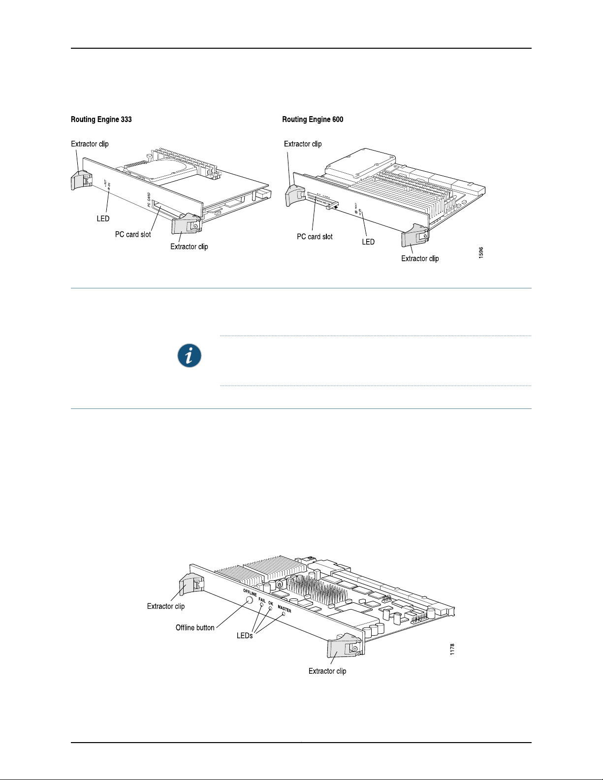
Figure 17: M40e Routing Engine 600
M40e Routing Engine 600 LEDS
The HD LED Indicates disk activity for the internal IDE interface. It does not necessarily
indicate routing-related activity.
Chapter 2: M40e Hardware Components
NOTE: The LEDs that report host module status (including Routing Engine
status) are on the craft interface rather than the Routing Engine faceplate.
M40e Miscellaneous Control Subsystem (MCS) Description
The Miscellaneous Control Subsystem (MCS) works with its companion Routing Engine
to provide control and monitoring functions for router components. It also generates a
clock signal for the SONET/SDH interfaces on the router.
One or two host modules (paired MCS and Routing Engine) can be installed into the
midplane from the rear of the chassis, as shownin “M40e Chassis Description”on page 8.
Only one host module is active ata time,with the optional second host module in standby
mode. For more information about host module interdependence and redundancy, see
“M40e Host Module Description” on page 23.
Figure 18: M40e Miscellaneous Control Subsystem
31Copyright © 2010, Juniper Networks, Inc.
Page 60

M40e Multiservice Edge Router Hardware Guide
Each MCS (shown in Figure 18 on page 31) has the following components:
•
PCI interface—Connects the MCS to the Routing Engine.
•
100-Mbps Ethernet switch—Carries signals and monitoring data between router
components.
•
19.44-MHz stratum 3 reference clock—Generates clock signal for SONET/SDH PICs.
•
I2C controller—Monitors the status of router components.
•
Three LEDs—Indicate MCS status. There is a blue one labeled MASTER, a green one
labeled OK, and an yellow one labeled FAIL. “M40e MCS LEDs” on page 33 describes
the LED states.
•
Offline button—Prepares the MCS for removal from the router when pressed.
•
Extractor clips—Control the locking system that secures the MCS in the chassis.
The MCS, in conjunction with the routing software, performs the functions:
•
Monitoring and control of router components—The MCS collects statistics from all
sensors in the system. When it detects a failure or alarm condition, it sends a signal to
the Routing Engine, which generates control messages or sets an alarm. The MCS also
relays control messages from the Routing Engine to the router components.
•
Controlling component power-up and power-down—The MCS controls the power-up
sequence of router components as they start, and powers down components when
their offline buttons are pressed.
•
Signaling of mastership—In a router with more than one host module, the MCS signals
to all router components which host module is the master and which is the standby.
It relays the mastership signal for the two PCGs as well.
•
Providing SONET/SDH clock source—The MCS generates a 19.44-MHz SONET/SDH
clock signal, along with a signal that indicates which MCS is the master SONET/SDH
clock generator (if two MCSs are installed).
•
Clock monitoring—The MCS monitors the PCG system clock and its SONET/SDH clock
to verify that they are providing the expected signal. It generates an alarm if a clock
signal is incorrect.
•
Control of FPC resets—If the MCS detects errors in an FPC, it attempts to reset the
FPC. After three unsuccessfulreset attempts, theMCS takes the FPC offline and informs
the Routing Engine. Other FPCs are unaffected, and system operation continues.
Copyright © 2010, Juniper Networks, Inc.32
Page 61

Figure 19: M40e and M160 Router MCS Location
Chapter 2: M40e Hardware Components
Related
Documentation
M40e MCS LEDs
M40e MCS LEDs on page 33•
• M40e Chassis Description on page 8
• Installing an MCS in an M40e Router on page 181
Three LEDs indicate MCSstatus. There is a blueone labeled MASTER, a green one labeled
OK, and an yellow one labeled FAIL. Table 6 on page 34 describes the LED states.
Figure 20: M40e Miscellaneous Control Subsystem
33Copyright © 2010, Juniper Networks, Inc.
Page 62

M40e Multiservice Edge Router Hardware Guide
Table 6: States for M40e MCS LEDs
DescriptionStateColorLabel
MCS is master.On steadilyBlueMASTER
MCS is functioning normally.On steadilyGreenOK
MCS is starting up.Blinking
MCS has failed.On steadilyYellowFAIL
Related
Documentation
M40e Miscellaneous Control Subsystem (MCS) Description on page 31•
• M40e Chassis Description on page 8
• Installing an MCS in an M40e Router on page 181
M40e Craft Interface Description
The craft interface provides status and troubleshooting information at a glance and has
buttons for deactivating alarms and preparing FPCs for removal. The craft interface is
located on the front of the chassis above the FPC card cage, as shown in “M40e Chassis
Description” on page 8. It includes the elements shown in Figure 21 on page 34.
Figure 21: M40e Craft Interface
Copyright © 2010, Juniper Networks, Inc.34
Page 63

Chapter 2: M40e Hardware Components
NOTE: The LEDs for some router components are located on the component
faceplate, rather than on the craft interface. For information about those
LEDs, see:
•
M40e Packet Forwarding Engine Clock Generators (PCGs) Description on
page 18
•
M40e Switching and Forwarding Module (SFM) Description on page 20
•
M40e Miscellaneous Control Subsystem (MCS) Description on page 31
•
M40e Power System Description on page 42
Related
Documentation
M40e Craft Interface Alarm LEDs and Controls on page 35•
• M40e Craft Interface LCD Description on page 36
• M40e Chassis Description on page 8
M40e Craft Interface Alarm LEDs and Controls
Two large alarm LEDs are located at the upper left of the craft interface (see “M40e
Craft Interface Description” on page 34). The circular red LED lights to indicate a critical
condition that canresult ina system shutdown. The triangular yellow LED lights toindicate
a less severe condition that requires monitoring or maintenance. Both LEDs can be lit
simultaneously.
A condition that causes an LED to light also activates the corresponding alarm relay
contacton the connector interface panel (CIP), as describedin “M40e Connector Interface
Panel (CIP) Description” on page 39. The LCD on the craft interface reports the cause of
the alarm, as described in “M40e Craft Interface LCD Description” on page 36.
To deactivate red and yellow alarms, press the button labeled ACO/LT (for “alarm
cutoff/lamp test”), which is located to theright of the alarm LEDs. Deactivating an alarm
turns off both LEDs and deactivates the device attached to the corresponding alarm
relay contact on the CIP. However, the LCD continues to report the alarm message until
you clear the condition that caused the alarm.
Table 7 on page 36 describes the alarm LEDs and alarm cutoff button in more detail.
35Copyright © 2010, Juniper Networks, Inc.
Page 64

M40e Multiservice Edge Router Hardware Guide
Table 7: Alarm LEDs and Alarm Cutoff/Lamp Test Button
DescriptionStateColorShape
On steadilyRed
On steadilyYellow
——
Related
Documentation
M40e PIC Overview•
• Host Module LEDs on the M40e Craft Interface on page 37
• M40e Chassis Description on page 8
M40e Craft Interface LCD Description
A four-line LCD is located in the craft interface, along with six navigation buttons. The
LCD operates in two modes:
•
LCD Idle Mode on page 36
•
LCD Alarm Mode on page 37
Critical alarm LED—Indicates a critical condition that
can cause the router to stop functioning. Possible
causes include component removal, failure, or
overheating.
Warningalarm LED—Indicates aserious but nonfatal
error condition, such as a maintenance alert or a
significant increase in component temperature.
Alarm cutoff/lamp test button—Deactivatesred and
yellowalarms. Causesall LEDs on the craft interface
to light (for testing purposes), when pressed and
held.
LCD Idle Mode
During normal operation, the LCD operates in idle mode and reports current status
information, as shown in Figure 22 on page 36.
Figure 22: LCD in Idle Mode
The lines in the display report the following information:
•
First line—Router name.
•
Second line—Length of time the router has been running, reported in the following
form:
Up days + hours:minutes
Copyright © 2010, Juniper Networks, Inc.36
Page 65

LCD Alarm Mode
Chapter 2: M40e Hardware Components
•
Third and fourth lines—Status messages, which rotate at 2-second intervals. Some
conditions, such as removal or insertion of a system component, can interrupt the
messages.
To add a message that alternates every 2 seconds with the default status messages,
use the set chassis display message command. For more information, see the Junos OS
System Basics and Services Command Reference.
When a red or yellow alarm occurs, the LCD switches to alarm mode and reports about
the alarm condition, as shown in Figure 23 on page 37.
Figure 23: M40e LCD in Alarm Mode
The lines in the display report the following information:
•
First line—Router name.
•
Second line—Number of active alarms.
•
Third and fourth lines—Individual alarm messages, with the most severe condition
shown first. The prefix on each line indicates whether the alarm is a red (R) or yellow (Y)
alarm.
For alist of alarm messages that canappear onthe LCD, see “M40e Chassis andInterface
Alarm Messages” on page 147.
Related
Documentation
M40e Craft Interface Alarm LEDs and Controls on page 35•
• M40e Craft Interface Description on page 34
• M40e Chassis Description on page 8
Host Module LEDs on the M40e Craft Interface
At the upper right corner of the craft interface (see “M40e Craft Interface Description”
on page 34)are two setsof LEDsthat indicate host modulestatus: the set labeled HOST0
reports the status of the Routing Engine in slot RE 0 and MCS in slot MCS 0, and the set
labeled HOST1 reports the status of the Routing Engine in slot RE 1 and the MCS in slot
MCS 1. Each set includes three LEDs—a green one labeled MASTER, another green one
labeled ONLINE, and a red one labeled OFFLINE. Table 8 on page 38 describes the LED
states.
37Copyright © 2010, Juniper Networks, Inc.
Page 66

M40e Multiservice Edge Router Hardware Guide
Table 8: States for M40e Host Module LEDs
DescriptionStateColorLabel
Host module is functioning as master.On steadilyGreenMASTER
Host module components(RoutingEngine andMCS)
are installed and functioning normally.
Host module is starting up.Blinking
One or both host module components are not
installed or have failed.
Related
Documentation
On steadilyGreenONLINE
On steadilyRedOFFLINE
M40e Craft Interface Alarm LEDs and Controls on page 35•
• M40e Craft Interface LCD Description on page 36
• M40e Host Module Description on page 23
FPC LEDs and Controls on the M40e Craft Interface
The LEDs and offline button for each FPC are located directly above it on the craft
interface, asshown in“M40e Craft Interface Description” on page 34.The red LEDlabeled
FAILand the green LED labeled OKindicateFPC status,as described in Table 9 on page 38.
The offline button, labeled with the FPC slot number (for example, FPC2), prepares the
FPC for removal from the router when pressed.
Table 9: States for M40e FPC LEDs
Related
Documentation
DescriptionStateColorLabel
FPC is functioning normally.On steadilyGreenOK
FPC is starting up or going offline.Blinking
FPC is offline or not installed.Off
FPC has failed.On steadilyRedFAIL
M40e FPCs Supported on page 17•
• M40e Craft Interface Description on page 34
• M40e Craft Interface LCD Description on page 36
Copyright © 2010, Juniper Networks, Inc.38
Page 67

M40e Connector Interface Panel (CIP) Description
The Connector Interface Panel (CIP) is located at the left side of the FPC card cage, as
shown in “M40e Chassis Description” on page 8. It houses Routing Engine management
ports and alarm relay contacts, as shown in Figure 24 on page 39.
Figure 24: Connector Interface Panel
Chapter 2: M40e Hardware Components
The CIPis located on the left sideof the M40eand M160 router Flexible PIC Concentrator
(FPC) card cage (see Figure 25 on page 40).
39Copyright © 2010, Juniper Networks, Inc.
Page 68

M40e Multiservice Edge Router Hardware Guide
Figure 25: M40e and M160 Router CIP Location
The CIP is field-replaceable, but is not hot-removable, hot-insertable, or hot-pluggable.
You must power down the router before removing or installing it.
•
Routing Engine Management Ports on page 40
•
BITS Input Ports on page 41
•
Alarm Relay Contacts on page 41
Routing Engine Management Ports
On the upper half of the CIP are two sets of ports for connecting the Routing Engines to
one or more external devices on which system administrators can issue Junos OS
command-line interface (CLI) commands to manage the router. The set of ports labeled
HOST0 connects to the Routing Enginein theslot labeled RE0, and theset labeled HOST1
connects to the Routing Engine in the slot labeled RE 1.
The ports with the indicated label in each set function as follows:
•
ETHERNET—Connects the Routing Engine through an Ethernet connection to a
management LAN (or any other device that plugs into an Ethernet connection) for
out-of-band management. The port uses an autosensing RJ-45 connector to support
both 10- and 100-Mbps connections. Two small LEDs on the left edge of the port
indicate the connection in use: the LED labeled ETHERNET lights yellow or green for a
10-Mbps or 100-Mbps connection, and the LED labeled ACT lights green when traffic
is passing through the port.
•
CONSOLE—Connects the Routing Engine to a system console through an RS-232
(EIA-232) serial cable.
•
AUXILIARY—Connects theRouting Engine to a laptop,modem, or other auxiliary device
through an RS-232 (EIA-232) serial cable.
Copyright © 2010, Juniper Networks, Inc.40
Page 69

Chapter 2: M40e Hardware Components
For information about the pinouts for the connectors, see “RJ-45 Connector Pinouts for
the M40e Routing Engine MGMT Port” on page 289.
Figure 26 on page 41 shows the ports that connect to the Routing Engine installed in slot
RE 0. The arrangement of ports for the Routing Engine installed in slot RE 1 is the same.
Figure 26: M40e Routing Engine Interface Ports for Host Module 0
BITS Input Ports
Alarm Relay Contacts
In thecenter ofthe CIP are twoports labeled BITSA and BITS B (see Figure 27 on page 42).
Use two DB-9 connectors to connect external clock inputs for 19.44-MHz Stratum 3
reference clocks (supported in Junos OS Release 8.3 and later).
For information about the pinouts for the connectors, see “DB-9 Connector Pinouts for
the M40eCIP BITSInput Ports” on page 293. For informationabout configuringan external
synchronization interface, see the Junos OS System Basics Configuration Guide.
At the bottom of the CIP are two relay contacts for connecting the router to external
alarm-reporting devices, the upper labeled RED ALARM and the lower YELLOW ALARM
(see Figure 27 on page 42). A system condition that causes the red or yellow alarm LED
to light on the craft interface also activates the corresponding alarm relay contact. For
instructions for attaching a device to the alarm relay contacts, see “Replacing Alarm
Relay Wires on the M40e Router” on page 167.
41Copyright © 2010, Juniper Networks, Inc.
Page 70

M40e Multiservice Edge Router Hardware Guide
Figure 27: M40e Alarm Relay Contacts and BITS Input Ports
Related
Documentation
M40e Chassis Description on page 8•
• M40e Router Physical Specifications on page 269
• M40e Router Power Requirements on page 274
M40e Power System Description
The M40e Multiservice Edge Router uses either AC or DC power. There are two
load-sharing, pass-through power supplies located at the bottom rear of the chassis, as
shown in “M40e Chassis Description” on page 8. The power supplies connect to the
midplane, which distributes power to router components according to their individual
voltage requirements. When the power supplies are installed and operational, they
automatically sharethe electrical load. Ifa power supply stopsfunctioning for anyreason,
the remaining power supplies instantly begin providing all the power the router needs
for normal functioning and can provide full power indefinitely.
CAUTION: Mixing AC and DC power supplies is not supported and prevents
the router from booting. If two power supplies are installed, they must either
both be AC or both DC.
A circuit breaker box must be installed on a DC-powered router, whereas a
circuit breaker is incorporated into each AC power supply.
Power supplies are hot-removable and hot-insertable, as described in “M40e
Field-Replaceable Units (FRUs)” on page 157. To avoid electrical injury, carefully follow
the instructions in Disconnecting AC Power from the M40e Router and Disconnecting
DC Power from the M40e Router.
Copyright © 2010, Juniper Networks, Inc.42
Page 71

NOTE: After powering off a power supply, wait at least 60 seconds before
turning itback on. Afterpowering on a power supply,wait at least 60 seconds
before turning it off.
If the systemis completely poweredoff whenyou poweron the powersupply,
the Routing Engine bootsas thepower supplycompletesits startupsequence.
If the Routing Engine finishes booting and you need to power off the system
again, see Disconnecting AC Power from the M40e Router or Disconnecting
DC Power from the M40e Router.
After a power supply is powered on, it can take up to 60 seconds for status
indicators—suchas LEDs on the power supply,show chassis commands, and
messages on the craft interface LCD—to indicate that the power supply is
functioning normally. Ignore error indicators that appear during the first 60
seconds.
Figure 28: M40e Router Power Supplies
Chapter 2: M40e Hardware Components
•
AC Power Supply on page 44
•
DC Power Supply on page 45
•
Circuit Breaker Box on a DC-Powered Router on page 47
•
Fuses on page 47
43Copyright © 2010, Juniper Networks, Inc.
Page 72

M40e Multiservice Edge Router Hardware Guide
AC Power Supply
An AC-powered router has two load-sharing, pass-through AC power supplies, located
at the bottom rear of the chassis, as shown in “M40e Chassis Description” on page 8.
Each AC power supply has the components (see Figure 29 on page 44):
•
One LED—Indicates power supply status. It is green and labeled OUTPUT OK. Table
10 on page 44 describes the LED states.
In addition, power supply failure triggers the red alarm LED on the craft interface and
the RED ALARM relay contact on the CIP. See “M40e Craft Interface Alarm LEDs and
Controls” on page 35.
•
Self-test button—Tests the power supply. Do not press this button; it is for use by
qualified service personnel only.
•
Internal fans—Cool the power supply.
Figure 29: M40e AC Power Supply
Table 10: States for M40e AC Power Supply LED
DescriptionStateColorLabel
Powersupply isinserted andis functioningnormally.On steadilyGreenOUTPUT OK
Blinking
slowly
rapidly
Table 11 on page 45 lists electrical specifications for the AC power supply.
Power supply is not plugged in, or power switch is in
off position (when other AC power supply is
functioning).
Power supply is starting up.Blinking
Copyright © 2010, Juniper Networks, Inc.44
Page 73

Chapter 2: M40e Hardware Components
Table 11: Electrical Specifications for AC Power Supply
SpecificationDescription
DC Power Supply
Maximum power output
AC input voltage
AC input current rating
Output voltages
NOTE: An AC-powered router can use only 220 VAC power (nominal range
200–240 VAC), not 110 VAC power (nominal range 100–120 VAC).
2900 W; isolated
3100 W; isolated
Nominal: 200 VAC, 208 VAC, 220 VAC, 240 VAC
Operating range: 180 to 264 VAC (2900 W)
Operating range: 198 to 264 VAC (3100 W)
47 to 63 HzAC input line frequency
15 A @ 200 V
13 A @ 240 V
+48 V @ 7.3 A (cooling system), +8 V @ 6 A (bias), –50 V @ 50 A
isolated
A DC-powered router has two load-sharing, pass-through DC power supplies, located
at the bottom rear of the chassis, as shown in “M40e Chassis Description” on page 8.
Each DC power supply has the components (see Figure 30 on page 46):
•
LEDs—Indicate power supply status. There is a green one labeled CB ON, a blue one
labeled OUTPUT OK, and an yellow one labeled CB OFF. Table 12 on page 46 describes
the LED states.
In addition, power supply failure triggers the red alarm LED on the craft interface and
the RED ALARM relay contact on the CIP. See “M40e Craft Interface Alarm LEDs and
Controls” on page 35.
•
Self-test button—Tests the power supply. Do not press this button; it is for use by
qualified service personnel only.
45Copyright © 2010, Juniper Networks, Inc.
Page 74

M40e Multiservice Edge Router Hardware Guide
Figure 30: M40e DC Power Supply
Table 12: States for M40e DC Power Supply LEDs
DescriptionStateColorLabel
On steadilyGreenCB ON
Blinking
On steadilyYellowCB OFF
Power supply is inserted correctly and is receiving
power. Circuit breaker is on.
Powersupply isinserted andis functioningnormally.On steadilyBlueOUTPUTOK
Power supply is not functioning, is starting up, or is
not properly inserted, or airflow is not sufficient.
Power supply is functioning, but the circuit breaker
is off.
Table 13 on page 46 lists electrical specifications for the DC power supply.
Table 13: M40e Electrical Specifications for DC Power Supply
SpecificationDescription
3150 W; nonisolatedMaximum power output
DC input voltage
Nominal: –48 VDC, –60 VDC
Operating range: –40.5 to –72 VDC
NOTE: If the input voltage from the DC power source drops below
–40.5 VDC, the platform automatically shuts down. During
automatic shutdown, the circuit remains active. When the input
voltage returns to –42.75 VDC, the platform automatically starts
up again and the system returns to normal operation within 30
minutes. No operator intervention is required.
Output voltages
80 A @ –48 VDC input current rating
+48 V @ 8.3 A (cooling system), +8.3 V @ 6 A (bias), –48 V to
–60 V@ 75 A
Copyright © 2010, Juniper Networks, Inc.46
Page 75

Circuit Breaker Box on a DC-Powered Router
On a DC-powered router, the circuit breaker box is located on the rear of the chassis,
above the right power supply, as shown in “M40e Chassis Description” on page 8. (On
an AC-powered router, the slot for the box is covered by a blank panel.)
The circuit breaker box houses two circuit breakers and sets of terminal studs,
corresponding positionally to the two power supplies, as shown in Figure 31 on page 47.
For proper router operation and power load sharing, connect a different external DC
power source to each set of terminal studs.
In addition, a grounding cable attaches to separate grounding points located above the
circuit breaker box, as shown in “M40e Chassis Description” on page 8. For more
information, see “M40e Chassis Grounding Specifications” on page 276.
Figure 31: M40e Circuit Breaker Box
Chapter 2: M40e Hardware Components
Fuses
Documentation
Related
The router uses fuses from the Cooper Bussman brand GMT series for the FPCs, MCSs,
PCGs, and SFMs. The fuses are located in a fuse box on the rear of the midplane. When
the fuse for a component blows, the component stops functioning even though it is
installed correctly and the power supplies are providing power to the router. For more
information, see “Using Blown Fuse Indicators to Troubleshoot the M40e Router” on
page 149. For fuse replacement instructions, see “Replacing a Fuse on an M40e Router”
on page 222.
M40e Router Power Requirements on page 274•
• M40e System Description on page 3
• General Electrical Safety Guidelines and Warnings Electrical Codes for M Series, MX
Series, and T Series Routers on page 251
47Copyright © 2010, Juniper Networks, Inc.
Page 76

M40e Multiservice Edge Router Hardware Guide
M40e Cooling System Description
The cooling system includes a fan tray and several impellers that draw room air into the
chassis to keep its internal temperature below a maximum acceptable level. When the
temperature is below the maximum, the fans and impellers function at less than full
speed. If the MCS detects that the temperature of a component has exceeded the
acceptable maximum—for example, because an impeller is removed—it automatically
increases the speed of the remaining impellers and fans to reduce the temperature. The
fans and impellers can function at the higher speed indefinitely.
•
Cooling System Components on page 48
•
Airflow Through the Chassis on page 48
Cooling System Components
The cooling system has the following components. All are hot-removable and
hot-insertable, as described in “M40e Field-Replaceable Units (FRUs)” on page 157.
•
Air intake vent, air filter, and intake cover—Provide an opening for room air to enter the
router. They are located at the bottom of the chassis front, below the cable
management system, as shown in “M40e Chassis Description” on page 8. The air filter
is removable and covers the air intake vent, preventing dust and other particles from
entering the cooling system. For maintenance and replacement instructions, see
“Maintaining the M40e Air Filter” on page 130. The nonremovable air intake cover is
located behind the air filter and provides EMC shielding.
•
Front cooling subsystem—Cools the FPCs, PICs, and midplane. It includes a fan tray
located behind the cable management system and a large, central impeller behind
the craft interface. For replacement instructions, see “Replacing the Fan Tray on an
M40e Router” on page 168 and “Replacing the M40e Front Impeller Assembly” on
page 172.
•
Rear cooling subsystem—Cools the SFMs, host module, PCGs, and power supplies. It
includes one impeller located at the upper right of the chassis rear and another at the
lower left, as shown in “M40e Chassis Description” on page 8. The upper and lower
impellers are not interchangeable. For replacement instructions, see “Replacing the
M40e Rear Lower Impeller Assembly”on page 175 and “Replacingthe M40eRear Upper
Impeller Assembly” on page 177.
Airflow Through the Chassis
Figure 32 on page 49 shows airflow through the chassis and the location of the impellers
and fan tray.
CAUTION: Do not remove the air filter for more than a few minutes while
the router is operating. Thefans and impellers arepowerful enough to draw
in foreign material, such as bits of wire, through the unfiltered air intake,
which could damage router components.
Copyright © 2010, Juniper Networks, Inc.48
Page 77

Figure 32: Airflow Through the M40e Chassis
Chapter 2: M40e Hardware Components
Related
Documentation
M40e Router Physical Specifications on page 269•
• M40e System Architecture Overview on page 59
• Routine Maintenance Procedures for the M40e Router on page 129
M40e Cable Management System Description
The cable management system (see Figure 33 on page 49) consists of a row of nine
semicircular plastic bobbins mounted on the front of therouter below the FPC card cage.
The PIC cables pass between the bobbins and into the tray, keeping the cables organized
and securely in place. The curvature of the bobbins also helps maintain the proper bend
radius for optical PIC cables.
Figure 33: M40e Cable Management System
Related
Documentation
• M40e Chassis Description on page 8
• M40e Router Physical Specifications on page 269
• M40e PIC Overview
49Copyright © 2010, Juniper Networks, Inc.
Page 78

M40e Multiservice Edge Router Hardware Guide
Copyright © 2010, Juniper Networks, Inc.50
Page 79

CHAPTER 3
Junos OS Overview
•
M40e Junos OS Overview on page 51
•
M40e Routing Engine Software Components on page 52
•
Tools for Accessing and Configuring the M40e Software on page 57
•
Tools for Monitoring the M40e Software on page 58
•
M40e Software Upgrades on page 58
M40e Junos OS Overview
The Junos OS isespecially designed for the largeproduction networks typically supported
by Internet Service Providers (ISPs). It incorporates InternetProtocol(IP) routing software
and software for management of interfaces, networks, and the router chassis.
The Junos OS runson theRouting Engine. The software consists of processes that support
Internet routing protocols, control the router's interfaces and the router chassis itself,
and provide an interface for system management. The processes run on top of a kernel
that coordinates the communicationamong processes and has a direct link to the Packet
Forwarding Engine software.
Related
Documentation
Use the Junos OS to configure the routing protocols that run on the router and the
properties of router interfaces. After you have activated a software configuration, use
the JunosOS tomonitor theprotocoltraffic passing throughthe router and to troubleshoot
protocol and network connectivity problems.
For additional information about the Junos OS, including its security features and a list
of theindustry standards itsupports, seethe JunosOS System Basics ConfigurationGuide.
For complete information about configuring the software, including examples, see the
Junos OS configuration guides.
NOTE: The router module supports Release 5.2 and later versions of the
Junos OS.
• M40e System Description on page 3
• M40e System Architecture Overview on page 59
• Initially Configuring the M40e Router on page 123
51Copyright © 2010, Juniper Networks, Inc.
Page 80

M40e Multiservice Edge Router Hardware Guide
M40e Routing Engine Software Components
The Routing Engine software consists of several software processes that control router
functions and a kernel that coordinates communication among the processes, as
described in:
•
Routing Protocol Process on page 52
•
VPNs on page 56
•
Interface Process on page 56
•
Chassis Process on page 57
•
SNMP and MIB II Processes on page 57
•
Management Process on page 57
•
Routing Engine Kernel on page 57
Routing Protocol Process
The Junos OS routing protocol process controls the routing protocols that run on the
router. The routing protocol process starts all configured routing protocols and handles
all routing messages. It consolidates the routing information learned from all routing
protocolsinto common routingtables. From this routing information, the routing protocol
process determines the active routes to network destinations and installs these routes
into the Routing Engine's forwarding table. Finally, the routing protocol process
implements the routing policies you specify, which determine how routing information
is transferred between the routing protocols and the routing table.
This section discusses:
•
IPv4 Routing Protocols on page 52
•
IPv6 Routing Protocols on page 54
•
Routing and Forwarding Tables on page 54
•
Routing Policy on page 55
For complete information aboutrouting concepts, seethe JunosOS configuration guides.
IPv4 Routing Protocols
The Junos OS implements full IP routing functionality, providing support for IP version 4
(IPv4). The routing protocols are fully interoperable with existing IP routing protocols
and provide the scale and control necessary for the Internet core. The software provides
support for the following routing and traffic engineering protocols:
Copyright © 2010, Juniper Networks, Inc.52
Page 81

Chapter 3: Junos OS Overview
•
Unicast routing protocols
•
BGP—Border Gateway Protocol, version 4, is an Exterior Gateway Protocol (EGP)
that guarantees loop-free exchange of routinginformation between routing domains
(also called autonomous systems). BGP, in conjunction with Junos routing policy,
provides a system of administrative checks and balances that can be used to
implement peering and transit agreements.
•
ICMP—Internet Control Message Protocol router discovery is a method that hosts
can use to discover the addresses of operational routers on a subnet.
•
IS-IS—Intermediate System-to-Intermediate System is a link-state interior gateway
protocol (IGP) for IP networks that uses the shortest-path-first algorithm (SPF
algorithm, also called the Dijkstra algorithm) to determine routes.
•
OSPF—Open Shortest Path First, version 2, is an IGP developed for IP networks by
the Internet Engineering Task Force (IETF). OSPF is a link-state protocol that makes
routing decisions based on the SPF algorithm.
•
RIP—Routing Information Protocol, version 2, is an IGP for IP networks based on the
Bellman-Ford algorithm. RIP is a distance-vector protocol. RIP dynamically routes
packets between a subscriber and a service provider without the subscriber having
to configure BGP or to participate in the service provider’s IGP discovery process.
•
Multicast routing protocols
•
DVMRP—Distance Vector Multicast Routing Protocol is a dense-mode
(flood-and-prune) multicast routing protocol.
•
IGMP—Internet Group Management Protocol, versions 1 and 2, is used to manage
membership in multicast groups.
•
MSDP—Multicast Source Discovery Protocol enables multiple PIM sparse mode
domains to be joined. A rendezvous point (RP) in a PIM sparse mode domain has a
peering relationship with an RP in another domain, thereby discovering multicast
sources from other domains.
•
PIM sparse mode and dense mode—Protocol-Independent Multicast is a multicast
routing protocol used to route traffic to multicast groups that might span wide-area
and interdomain internetworks. In PIM sparse mode, routers explicitly join and leave
multicast groups. PIM dense mode is a flood-and-prune protocol.
•
SAP/SDP—Session Announcement Protocol andSession DescriptionProtocolhandle
conference session announcements.
•
MPLS application protocols
•
LDP—Label Distribution Protocol provides a mechanism for distributing labels in
nontraffic-engineered applications. LDP allows routers to establish label-switched
paths (LSPs) through a network by mapping network-layer routing information
directly to data-link layer switched paths. LSPs created by LDP can also traverse
LSPs created by Resource Reservation Protocol (RSVP).
53Copyright © 2010, Juniper Networks, Inc.
Page 82

M40e Multiservice Edge Router Hardware Guide
•
MPLS—Multiprotocol Label Switching enables you to configure LSPs through a
network either manually or dynamically. You can control how traffic traverses the
network by directing it through particular paths, rather than relying on an IGP's
least-cost algorithm to choose a path.
•
RSVP—Resource Reservation Protocol, version 1, provides a mechanism for
engineering network traffic patterns that is independent of the shortest path
determined by a routing protocol.RSVPitself isnot a routing protocol,but is designed
to operate with current and future unicast and multicast routing protocols. Junos
RSVP software supports dynamic signaling for MPLS LSPs.
IPv6 Routing Protocols
The Junos OS implements full IP routing functionality, providing support for IP version 6
(IPv6). The routing protocols are fully interoperable with existing IP routing protocols
and provide the scale and control necessary for the Internet core. The software provides
support for the following unicast routing protocols:
•
BGP—Border GatewayProtocol,version 4, is an EGP that guarantees loop-free exchange
of routing information between routing domains (also called autonomous systems).
BGP, in conjunction with Junos routing policy, provides a system of administrative
checks and balances that can be used to implement peering and transit agreements.
•
ICMP—Internet Control Message Protocol router discovery is a method that hosts can
use to discover the addresses of operational routers on a subnet.
•
IS-IS—Intermediate System-to-Intermediate System is a link-state interior gateway
protocol (IGP) for IP networks that uses the shortest-path-first algorithm (SPF
algorithm, also called the Dijkstra algorithm) to determine routes.
•
OSPF—Open Shortest Path First,version 3(OSPFv3), supports version 6 of theInternet
Protocol (IPv6). The fundamental mechanisms of OSPF such as flooding, Designated
Router (DR) election, area based topologies and the Shortest Path First (SPF)
calculations remainunchanged. Some differences existeither due to changesin protocol
semantics between IPv4 and IPv6, or to handle the increased address size of IPv6.
•
RIP—Routing Information Protocol, version 2, is an IGP for IP networks based on the
Bellman-Ford algorithm. RIP is a distance-vector protocol. RIP dynamically routes
packets between a subscriber and a service provider without the subscriber having to
configure BGP or to participate in the service provider’s IGP discovery process.
Routing and Forwarding Tables
The primary function of the Junos routing protocol process is maintaining routing tables
and using the information in them to determine active routes to network destinations. It
copies information about the active routes into the Routing Engine's forwarding table,
which the Junos kernel copies to the Packet Forwarding Engine.
By default, the routing protocol process maintains the following routing tables and uses
the information in each table to determine active routes to network destinations:
•
Unicast routing table—Stores routing information for all unicast protocols running on
the router, including BGP, IS-IS, OSPF, and RIP. You can also configure additional
Copyright © 2010, Juniper Networks, Inc.54
Page 83

Chapter 3: Junos OS Overview
routes, such as static routes, for inclusion in the routing table. The unicast routing
protocols use the routes in this table when advertising routing information to their
neighbors.
In the unicast routing table, the routing protocol process designates routes with the
lowest preference values as active. By default, a route's preference value is simply a
function of how the routing protocol process learned about the route. You can modify
the default preference value by setting routing policies and configuring other software
parameters. See “Routing Policy” on page 55.
•
Multicast routing table (cache)—Stores routing information for all multicast protocols
running on the router, including DVMRP and PIM. You can configure additional routes
for inclusion in the routing table.
In the multicast routing table, the routing protocol process uses traffic flow and other
parameters specified by the multicast routing protocol algorithms to select active
routes.
•
MPLS routing table—Stores MPLS label information.
For unicast routes, the routing protocol process determines active routes by choosing
the most preferred route, which is the route with the lowest preference value. By default,
the route’s preference value is simply a function of how the routing protocol process
learned about the route. You canmodify the default preference value using routing policy
and with software configuration parameters.
For multicast traffic, the routing protocol process determines active routes based on
traffic flow and other parameters specified by the multicast routing protocol algorithms.
The routing protocol process then installs one or more active routes to each network
destination into the Routing Engine’s forwarding table.
You can configure additional routing tables to meet your requirements, as described in
the Junos OS Routing Protocols Configuration Guide.
Routing Policy
By default, allrouting protocols place their routes into the routing table. When advertising
routes, the routing protocols, by default, advertise only a limited set of routes from the
routing table. Specifically, each routing protocol exports only the active routes that were
learned by that protocol. In addition, IGPs (IS-IS, OSPF, and RIP) export the direct
(interface) routes for the interfaces on which the protocol is explicitly configured.
For each routing table, you can affect the routes that a protocol places into the table
and theroutes from the table thatthe protocol advertises by defining one or more routing
policies and then applying them to the specific routing protocol.
Routing policies applied when the routing protocol places routes into the routing table
are called import policies because the routes are being imported into the routing table.
Policies applied when the routing protocol is advertising routes that are in the routing
table are called export policies because the routes are being exported from the routing
table. In other words, the terms import and export are used with respect to the routing
table.
55Copyright © 2010, Juniper Networks, Inc.
Page 84

M40e Multiservice Edge Router Hardware Guide
Routing policy enables you to control (filter) which routes are imported into the routing
table and which routes are exported from the routing table. Routing policy also allows
you to set the information associated with a route as it is being imported into or exported
from the routing table. Routing policies applied to imported routes control the routes
used to determine active routes, whereas policies applied to exported routes control
which routes a protocol advertises to its neighbors.
You implement routing policy by defining policies. A policy specifies the conditions to
use to match a route and the action to perform on the route when a match occurs. For
example, when a routing table imports routing information from a routing protocol, a
routing policy might modify the route's preference, mark the route with acolor to identify
it for later manipulation, or prevent the route from even being installed in a routing table.
When a routing table exports routes to a routing protocol, a policy might assign metric
values, modify the BGP community information, tag the route withadditional information,
or prevent the route from being exported altogether. You also can define policies for
redistributing the routes learned from one protocol into another protocol.
VPNs
Interface Process
The Junos OS supports several types of VPNs:
•
Layer 2 VPNs—A Layer 2 VPN links a set of sites sharing common routing information,
and whose connectivity is controlled by a collection of policies. A Layer 2 VPN is not
aware of routes within a customer’s network. It simply provides private links between
a customer’s sites over the service provider’s existing public Internet backbone.
•
Layer3 VPNs—ALayer 3 VPN linksa setof sitesthat share commonrouting information,
and whose connectivity is controlled by a collection of policies. A Layer 3 VPN is aware
of routes within a customer’s network, requiring more configuration on the part of the
service provider than a Layer2 VPN. The sitesthat make up a Layer3 VPN are connected
over a service provider’s existing public Internet backbone.
•
Interprovider VPNs—An interprovider VPN supplies connectivity between two VPNs in
separate autonomous systems (ASs). This functionality could be used by a VPN
customer with connections to several various ISPs, or different connections to the
same ISP in various geographic regions.
•
Carrier-of-Carrier VPNs—Carrier-of-carrier VPNs allow a VPN service provider to supply
VPN service to a customer who is also a service provider. The latter service provider
supplies Internet or VPN service to an end customer.
The Junos interfaceprocess manages the physical interface devices and logical interfaces
on the router. It implements the Junos OS command-line interface (CLI) commands and
configuration statements that you use to specify interface properties such as location
(FPC location in the FPC card cage and PIC location on an FPC), the interface type (such
as SONET/SDH or ATM), encapsulation, and interface-specific properties. You can
configure both interfaces that are currently active and interfaces that might be installed
later.
Copyright © 2010, Juniper Networks, Inc.56
Page 85

The Junos interface process communicates with the interface process in the Packet
Forwarding Engine through the Junos kernel, enabling the Junos OS to track the status
and condition of router interfaces.
Chassis Process
The Junos chassis process allows youto configure and control the properties of the router,
including conditions that trigger alarms and clock sources. The chassis process
communicates directly with a chassis process in the Junos kernel.
SNMP and MIB II Processes
The Junos OS supports the Simple Network Management Protocol (SNMP), versions 1,
2, and3, whichprovides a mechanism for monitoringthe state ofthe router. This software
is controlled by the Junos SNMP and Management Information Base (MIB) II processes,
which consist of an SNMP master agent and a MIB II agent.
Management Process
The management process starts all the other Junos OS processes and the CLI when the
router boots. It monitors the running Junos processes andmakes allreasonableattempts
to restart any process that terminates.
Chapter 3: Junos OS Overview
Routing Engine Kernel
The Routing Engine kernel provides the underlying infrastructure for all Junos OS
processes. It also provides the link between the routing tables maintained by the routing
protocolprocess and the forwarding table maintained by the Routing Engine.Additionally,
it coordinates communication withthe Packet Forwarding Engine,which primarilyinvolves
synchronizing the Packet ForwardingEngine’s forwarding table with the masterforwarding
table maintained by the Routing Engine.
Related
Documentation
M40e Routing Engine Architecture on page 61•
• M40e Routing Engine Description on page 26
Tools for Accessing and Configuring the M40e Software
The Junos OS CLI is the primary tool for accessing and controlling the Junos OS. You use
it when accessing the router through the console or a connection to an out-of-band
management network. The CLI includes commands for configuring router hardware, the
Junos OS, and network connectivity.
The Junos OS CLI is a straightforward command interface. You type commands on a
single line and enter thecommands by pressingthe Enterkey. TheCLI provides command
help and command completion, as well as Emacs-style keyboard sequences for moving
around ona commandline and scrolling through a buffer that containsrecently executed
commands. For more information about the CLI, see the Junos OS System Basics
Configuration Guide.
Related
Documentation
M40e System Description on page 3•
• M40e System Architecture Overview on page 59
57Copyright © 2010, Juniper Networks, Inc.
Page 86

M40e Multiservice Edge Router Hardware Guide
• Initially Configuring the M40e Router on page 123
Tools for Monitoring the M40e Software
In addition to commands for configuring router hardware and software, the CLI includes
commands for monitoring and troubleshooting hardware, software, routing protocols,
and network connectivity. CLI commands display information from routing tables,
information specific to routing protocols, and information about network connectivity
derived from the ping and traceroute utilities.
You can also use the Junos OS implementation of SNMP to monitor routers. The SNMP
software consists of an SNMP master agent and a MIB II agent. It provides full support
for MIB II SNMPversion 1traps andversion 2notifications, SNMPversion 1 Get and GetNext
requests, and version 2 GetBulk requests. For more information about SNMP, see the
Junos OS Network Management Configuration Guide.
The software also supports tracing and logging operations, which you can use to track
normal router operations, error conditions, and the packets that the router generates or
forwards. Logging operations use a syslog-like mechanism to record systemwide,
high-level events such as interfaces going up or down and user logins on the router.
Tracing operations record more detailed information about the operation of routing
protocols, such as the various types of routing protocol packets sent and received, and
routing policy actions.
Related
Documentation
M40e System Description on page 3•
• M40e System Architecture Overview on page 59
• Initially Configuring the M40e Router on page 123
M40e Software Upgrades
The M40e MultiService Edge Router is delivered with the Junos OS preinstalled. To
upgrade the software, you use CLI commands to copy a set of software images over the
network to memory storage on the Routing Engine. The Junos OS set consists of several
images provided inindividual packages or as a bundle. You normally upgrade all packages
simultaneously. For information about installing and upgrading Junos OS, see the Junos
OS Installation and Upgrade Guide.
Related
Documentation
• M40e System Description on page 3
• M40e System Architecture Overview on page 59
• Initially Configuring the M40e Router on page 123
Copyright © 2010, Juniper Networks, Inc.58
Page 87

CHAPTER 4
M40e System Architecture Overview
•
M40e System Architecture Overview on page 59
•
M40e Packet Forwarding Engine Architecture on page 60
•
M40e Routing Engine Architecture on page 61
M40e System Architecture Overview
•
Packet Forwarding Engine—Performs Layer 2 and Layer 3 packet switching, route
lookups, and packet forwarding.
•
Routing Engine—Provides Layer 3 routing services and network management.
The Packet Forwarding Engine and the Routing Engine perform independently but
communicate constantly through a 100-Mbps internal link. This arrangement provides
streamlined forwarding and routing control and the ability to run Internet-scale networks
at high speeds. Figure 34 on page 59 illustrates the relationship between the Packet
Forwarding Engine and the Routing Engine.
Related
Documentation
Figure 34: System Architecture
M40e System Redundancy on page 4•
• M40e System Description on page 3
• M40e PIC Overview
59Copyright © 2010, Juniper Networks, Inc.
Page 88

M40e Multiservice Edge Router Hardware Guide
M40e Packet Forwarding Engine Architecture
The Packet Forwarding Engine performs Layer 2 and Layer 3 packet switching.
•
Packet Forwarding Engine Components on page 60
•
Data Flow Through the Packet Forwarding Engine on page 60
Packet Forwarding Engine Components
The Packet Forwarding Engine is implemented in application-specific integrated circuits
(ASICs). It uses a centralized route lookup engine and shared memory.
The Packet Forwarding Engine architecture includes the components:
•
Midplane—Transports packets, notifications, and other signals between the FPCs and
the Packet Forwarding Engine (as well as other system components).
•
Physical Interface Card (PIC)—Physically connects the router to fiber-optic or digital
network media. A controller ASIC in each PIC performs control functions specific to
the PIC media type.
•
Flexible PIC Concentrators (FPCs)—House PICs and provide shared memory for
processing incoming and outgoing packets. Each FPC hosts two I/O Manager ASICs,
one active and one in standby mode. The active I/O Manager ASIC divides incoming
data packets into memory blocks (cells) before passing them to the active SFM, and
reassembles cells into data packets when the packets are ready for transmission. The
FPC also hosts two Packet Director ASICs—one concentrates incoming packets to the
active I/O ManagerASIC, andthe other distributes outgoing packetsto the appropriate
PICs on the FPC.
•
Switching and Forwarding Module (SFM)—Hosts an Internet Processor II ASIC, which
makes forwarding decisions,and two DistributedBuffer Manager ASICs:one distributes
data cells to the shared memory buffers on the FPCs and the other notifies the FPCs
of forwarding decisions for outgoing packets.
Data Flow Through the Packet Forwarding Engine
Use of ASICs promotes efficient movement of data packets through the system. Packets
flow through the Packet Forwarding Engine in the sequence (see Figure 35 on page 61):
1. Packets arrive at an incoming PIC interface.
2. The PIC passes the packets to the FPC, where the Packet Director ASIC directs them
to the active I/O Manager ASIC.
3. The I/O ManagerASIC processes thepacket headers, divides the packetsinto 64-byte
data cells, and passes the cells through the midplane to the SFM.
4. A Distributed Buffer Manager ASIC on the SFM distributes the data cells throughout
the memory buffers located on and shared by all the FPCs.
5. The Internet Processor II ASIC on the SFM performs a route lookup for each packet
and decides how to forward it.
Copyright © 2010, Juniper Networks, Inc.60
Page 89

Chapter 4: M40e System Architecture Overview
6. The Internet Processor II ASIC notifies the second Distributed Buffer Manager ASIC
(on the SFM) of the forwarding decision, and the Distributed Buffer Manager ASIC
forwards the notification to the FPC that hosts the appropriate outbound interface.
7. The I/O Manager ASIC on the FPC reassembles data cells stored in shared memory
into data packets as they are ready for transmission and passes them through the
Packet Director ASIC to the outbound PIC.
8. The outbound PIC transmits the data packets.
Figure 35: Packet Forwarding Engine Components and Data Flow
Related
Documentation
M40e PCG LEDs on page 19•
• M40e Packet Forwarding Engine Clock Generators (PCGs) Description on page 18
• Installing a PCG in an M40e Router on page 197
M40e Routing Engine Architecture
The Routing Engine runs Junos OS, which Juniper Networkshas developed andoptimized
to handle large numbers of network interfaces and routes. The software consists of a
set ofsystem processes running in protected memory modules on top of anindependent
operating system. The Junos kernel supports Junos system processes, which handle
system management processes, routing protocols, and control functions (see Figure 36
on page 62).
The Routing Engine has a dedicated 100-Mbps internal connection to the Packet
Forwarding Engine.
61Copyright © 2010, Juniper Networks, Inc.
Page 90

M40e Multiservice Edge Router Hardware Guide
Figure 36: M40e Routing Engine Architecture
•
Routing Engine Functions on page 62
Routing Engine Functions
The Routing Engine handles all routing protocol processes, as well as the software
processes that control the router's interfaces, the chassis components, system
management, and user access to the router. These routing and software processes run
on topof a kernel that interacts withthe Packet ForwardingEngine. For more information
about the processes, see the Junos OS System Basics and Services Command Reference.
The Routing Engine includes the functions and features:
•
Processing of routing protocol packets—The Routing Engine handles all packets that
concern routing protocols, freeingthe Packet Forwarding Engine to handle only packets
that represent Internet traffic.
•
Softwaremodularity—Becauseeach software process is devoted to a different function
and uses a separate process space, the failure of one process has little or no effect on
the others.
•
In-depth Internet functionality—Each routingprotocolis implemented witha complete
set ofInternet features and provides full flexibilityfor advertising, filtering,and modifying
routes. Routing policies are set according to route parameters (for example, prefix,
prefix lengths, and Border Gateway Protocol [BGP] attributes).
•
Scalability—The Junos routing tables have been designed to hold all the routes in
current networks with ample capacity for expansion. Additionally, the Junos OS can
efficiently support large numbers of interfaces and virtual circuits.
•
Management interface—Different levels of system management tools are provided,
including the Junos OS command-line interface (CLI), the Junos XML management
protocol, the craft interface, and SNMP.
•
Storage andchange management—Configurationfiles, system images, andmicrocode
can be held and maintained in primary and secondary storage systems, permitting
local or remote upgrades.
•
Monitoring efficiency and flexibility—The router supports functions such as alarm
handling and packet counting on every port, without degrading packet-forwarding
performance.
Copyright © 2010, Juniper Networks, Inc.62
Page 91

Chapter 4: M40e System Architecture Overview
The Routing Engine constructs and maintains one or more routing tables (see Figure 37
on page 63). From the routing tables, the Routing Engine derives a table of active routes,
called the forwarding table, which is then copied into the Packet Forwarding Engine. The
design of the ASICs allow the forwarding table in the Packet Forwarding Engine to be
updated without interrupting forwarding performance.
Figure 37: Control Packet Handling for Routing and Forwarding Table
Updates
Related
Documentation
• Installing a Routing Engine in an M40e Router on page 189
• M40e Routing Engine Description on page 26
63Copyright © 2010, Juniper Networks, Inc.
Page 92

M40e Multiservice Edge Router Hardware Guide
Copyright © 2010, Juniper Networks, Inc.64
Page 93

PART 2
Setting Up the M40e Router
•
Preparing the Site for M40e Router Installation on page 67
•
Unpacking the M40e Router on page 73
•
Installing the M40e Router Mounting Hardware on page 77
•
Installing the M40e Router Using a Mechanical Lift on page 81
•
Installing the M40e Router Without a Mechanical Lift on page 83
•
Grounding the M40e Router on page 109
•
Connecting the M40e Router to External Devices on page 111
•
Providing Power to the M40e Router on page 119
•
Configuring Junos OS on page 123
65Copyright © 2010, Juniper Networks, Inc.
Page 94

M40e Multiservice Edge Router Hardware Guide
Copyright © 2010, Juniper Networks, Inc.66
Page 95

CHAPTER 5
Preparing the Site for M40e Router
Installation
•
M40e Site Preparation Checklist on page 67
•
M40e Rack Requirements on page 68
•
M40e Clearance Requirements for Airflow and Hardware Maintenance on page 71
M40e Site Preparation Checklist
The checklist in Table 14 on page 67 summarizes the tasks you need to perform when
preparing a site for router installation.
Table 14: Site Preparation Checklist
Environment
Verify that environmental factors such as
temperatureand humidity donot exceedrouter
tolerances.
“M40e Router Environmental
Specifications” on page 271
DatePerformed ByFor More InformationItem or Task
Power
Measure distance between external power
sources and router installation site.
Locate sites for connection of system
grounding.
Calculate the power consumption and
requirements.
Hardware Configuration
Choose the configuration.
Rack
“M40e AC Power, Connection, and
Power Cord Specifications” on
page 277
“M40e DC Power, Connection, and
Cable Specifications” on page 279
“M40e Chassis Grounding
Specifications” on page 276
“M40e Router Power Requirements”
on page 274
67Copyright © 2010, Juniper Networks, Inc.
Page 96

M40e Multiservice Edge Router Hardware Guide
Table 14: Site Preparation Checklist (continued)
DatePerformed ByFor More InformationItem or Task
Verify that your rack meets the minimum
requirements for the installation of the router.
Plan rack location, including required space
clearances.
If arack isused, secure rack to floorand building
structure.
Cables
Acquire cables and connectors:
•
Determine the number of cables needed
based on your planned configuration.
•
Review the maximum distance allowed for
each cable. Choosethe length of cable based
on the distance between the hardware
components being connected.
Plan the cable routing and management.
Related
Documentation
M40e Chassis Description on page 8•
• M40e Router Physical Specifications on page 269
“M40e Rack Size and Strength” on
page 69
“M40e Clearance Requirements for
Airflow and Hardware Maintenance”
on page 71
“M40e Connection to Building
Structure” on page 71
“Calculating Power Budget for
Fiber-Optic Cable for M Series, MX
Series, and T Series Routers” on
page 285
“Calculating Power Margin for
Fiber-Optic Cable for M Series, MX
Series, and T Series Routers” on
page 286
“Maintaining M40e PICs and PIC
Cables” on page 139
• M40e Chassis Lifting Guidelines on page 235
• General Safety Guidelines and Warnings for M Series, MX Series, and T Series Routers
on page 229
• M40e Router Environmental Specifications on page 271
M40e Rack Requirements
The M40e Multiservice Edge Router must be installed in a rack. Many types of racks are
acceptable, including 4-post (telco) racks and open-frame racks. An example of a
open-frame rack appears in “M40e Rack Size and Strength” on page 69.
The following sections describe rack requirements:
•
M40e Rack Size and Strength on page 69
•
Spacing of the M40e Mounting Holes on page 70
•
M40e Connection to Building Structure on page 71
Copyright © 2010, Juniper Networks, Inc.68
Page 97

M40e Rack Size and Strength
The router is designed for installation ina 19-in. rack as defined in Cabinets, Racks, Panels,
and Associated Equipment (document number EIA-310-D) published by the Electronics
Industry Association (http://www.eia.org).
With the use ofadapters, therouter is designed to fit into a 600-mm-wide rack, as defined
in the four-part Equipment Engineering (EE); European telecommunications standard for
equipment practice (document numbers ETS 300 119-1 through 119-4) published by the
European Telecommunications Standards Institute (http://www.etsi.org). Use approved
wing devices to narrow the opening between the rails.
The rack rails must be spaced widely enough to accommodate the router chassis's
external dimensions: 35 in. (89 cm) high, 29 in. (73.6 cm) deep, and 17.5 in. (44.5 cm)
wide. The outer edges of the front support posts and center-mounting brackets extend
the width to 19 in. (48.3 cm). The spacing of rails and adjacent racks must also allow for
the clearances around the router and rack that are specified in “M40e Clearance
Requirements for Airflow and Hardware Maintenance” on page 71.
Chapter 5: Preparing the Site for M40e Router Installation
The chassis height of 35 in. (89 cm) is approximately 20 U. A U is the standard rack unit
defined in Cabinets, Racks, Panels, and Associated Equipment (document number
EIA-310-D) published by the Electronics Industry Association. You can stack two M40e
routers in a rack that has at least 40 U (70 in. or 1.78 m) of usable vertical space.
The rack must be strong enough to support the weight of the fully configured router, up
to approximately 360 lb (164 kg). If you stack two fully configured routers in one rack, it
must be capable of supporting about 720 lb (328 kg).
69Copyright © 2010, Juniper Networks, Inc.
Page 98

M40e Multiservice Edge Router Hardware Guide
Figure 38: Typical Open-Frame Rack
Related
Documentation
Rack-Mounting M40e Hardware Description on page 77•
• M40e Site Preparation Checklist on page 67
• M40e Chassis Description on page 8
• M40e Router Physical Specifications on page 269
Spacing of the M40e Mounting Holes
Table 15 on page 70 specifies the spacing between mounting holes in the chassis’s front
support postsand center-mounting brackets. Themounting holes in a front-mount rack’s
rails must align with the holes in the front support posts, and the mounting holes in a
center-mount rack’s rails must align with the holes in the center-mounting brackets.
Table 15: Spacing of Holes on M40e Front Support Post and
Center-Mounting Bracket
Hole SpacingRouter Mounting Rail
4 U (7 in. or 17.78 cm)Front support post
Copyright © 2010, Juniper Networks, Inc.70
Page 99

Chapter 5: Preparing the Site for M40e Router Installation
Table 15: Spacing of Holes on M40e Front Support Post and
Center-Mounting Bracket (continued)
Hole SpacingRouter Mounting Rail
3 U (5.25 in. or 13.33 cm)Center-mounting bracket
Related
Documentation
M40e Site Preparation Checklist on page 67•
• M40e Chassis Description on page 8
• M40e Router Physical Specifications on page 269
M40e Connection to Building Structure
Always secure the rack to the structure of the building. If your geographical area is subject
to earthquakes, bolt the rack to the floor. For maximum stability, also secure the rack to
ceiling brackets. For more information, see “Rack-Mounting Requirements and Warnings
for M Series, MX Series, and T Series Routers” on page 236.
Related
Documentation
M40e Site Preparation Checklist on page 67•
• M40e Chassis Description on page 8
• M40e Router Physical Specifications on page 269
M40e Clearance Requirements for Airflow and Hardware Maintenance
When planning the installation site, you must allow sufficient clearance around the rack
(see Figure 39 on page 72):
•
For the cooling system to function properly, the airflow around the chassis must be
unrestricted. “M40e Cooling System Description” on page 48 depicts the airflow in the
router.
NOTE: If you mount the router in a cabinet, be sure that ventilation is
sufficient to prevent overheating.
•
For service personnel to remove and install hardware components, there must be
adequate space at the front and back of the router. At least 24 in. (61 cm) is required
both in front of and behind the router. NEBS GR-63 recommends that you allow at
least 30 in. (72.6 cm) in front of the rack and 24 in. (61 cm) behind the rack.
71Copyright © 2010, Juniper Networks, Inc.
Page 100

M40e Multiservice Edge Router Hardware Guide
Figure 39: M40e Chassis Dimensions and Clearance Requirements
Related
Documentation
• M40e Site Preparation Checklist on page 67
• M40e Chassis Description on page 8
• M40e Router Physical Specifications on page 269
Copyright © 2010, Juniper Networks, Inc.72
 Loading...