

Page 1
12.12 -
11.14
51289390
DFG/TFG 660-690
Operating instructions G
TFG 680
DFG 670
DFG 680
DFG 690
DFG S80
DFG S90
TFG 660
TFG 670
TFG 690
TFG S80
TFG S90
DFG 660
Page 2

3
11.14 E N
Declaration of Conformity
Jungheinrich AG, Am Stadtrand 35, D-22047 Hamburg
Manufacturer or agent acting in the European Union
Additional information
On behalf of
Date
G
EU Conformity Declaration
The undersigned hereby declare that the powered industrial truck described below in
detail complies with the European Directives 2006/42/EC (Machinery Directive) and
2004/108/EEC (Electromagnetic Compatibility - EMC) including amendments as well
as the legislative decree to incorporate the directives in national law. The signatories
are in each case individually authorized to compile the technical documents.
Type Option Serial no. Year of
manufacture
DFG 660
DFG 670
DFG 680
DFG 690
DFG S80
DFG S90
TFG 660
TFG 670
TFG 680
TFG 690
TFG S80
TFG S90
G
Page 3

11.14 E N
4
Page 4

5
11.14 E N
Foreword
Notes on the operating instructions
The present ORIGINAL OPERATING INSTRUCTIONS are designed to provide
sufficient instruction for the safe operation of the industrial truck. The information is
provided clearly and concisely. The chapters are arranged by letter and the pages are
numbered continuously.
The operator manual details different industrial truck models. When operating and
servicing the industrial truck, make sure that the particular section applies to your
truck model.
Our trucks are subject to ongoing development. Jungheinrich reserves the right to
alter the design, equipment and technical features of the system. No guarantee of
particular features of the truck should therefore be assumed from the present
operating instructions.
Safety notices and text mark-ups
Safety instructions and important explanations are indicated by the following
graphics:
DANGER!
Indicates an extremely hazardous situation. Failure to comply with this instruction will
result in severe irreparable injury and even death.
WARNING!
Indicates an extremely hazardous situation. Failure to comply with this instruction
may result in severe irreparable injury and even death.
CAUTION!
Indicates a hazardous situation. Failure to comply with this instruction may result in
slight to medium injury.
NOTE
Indicates a material hazard. Failure to comply with this instruction may result in
material damage.
Z Used before notices and explanations.
t Indicates standard equipment
o Indicates optional equipment
Page 5

11.14 E N
6
Copyright
Copyright of these operating instructions remains with JUNGHEINRICH AG.
Jungheinrich Aktiengesellschaft
Am Stadtrand 35
22047 Hamburg - Germany
Tel: +49 (0) 40/6948-0
www.jungheinrich.com
Page 6

7
11.14 E N
Contents
A Correct Use and Application ................................................... 11
1 General.................................................................................................... 11
2 Correct application................................................................................... 11
3 Approved application conditions.............................................................. 12
4 Proprietor responsibilities ........................................................................ 13
5 Adding attachments and/or optional equipment ...................................... 13
B Truck Description .................................................................... 15
1 Application ............................................................................................... 15
1.1 Truck models and rated capacity............................................................. 15
2 Assemblies and Functional Description................................................... 16
2.1 Assembly Overview ................................................................................. 16
2.2 Functional Description ............................................................................. 17
3 Technical Specifications .......................................................................... 19
3.1 Performance data .................................................................................... 19
3.2 Dimensions .............................................................................................. 23
3.3 Weights.................................................................................................... 28
3.4 Mast versions .......................................................................................... 29
3.5 Tyre type.................................................................................................. 33
3.6 Engine Data ............................................................................................. 35
3.7 EN norms................................................................................................. 36
3.8 Conditions of use ..................................................................................... 37
3.9 Electrical requirements ............................................................................ 37
4 Identification points and data plates ........................................................ 38
4.1 Data plate ................................................................................................ 40
4.2 Truck capacity plate................................................................................. 41
4.3 Attachment capacity plate ....................................................................... 42
4.4 Jack attachment point.............................................................................. 42
5 Stability .................................................................................................... 42
C Transport and Commissioning ................................................ 43
1 Transport ................................................................................................. 43
2 Truck laden.............................................................................................. 43
2.1 Centre of gravity of the truck ................................................................... 43
2.2 Lifting the truck by crane ......................................................................... 44
2.3 Loading with another industrial truck ....................................................... 45
3 Securing the truck during transport ......................................................... 46
4 Using the Truck for the First Time ........................................................... 47
Page 7

11.14 E N
8
D Fuelling the Truck.................................................................... 49
1 General.................................................................................................... 49
1.1 Safety regulations for handling diesel fuel and LPG................................ 49
1.2 LPG system relief valve ........................................................................... 51
2 Adding diesel ........................................................................................... 52
2.1 Fuelling .................................................................................................... 52
2.2 Fuelling with fuel containers .................................................................... 53
3 LPG containers........................................................................................ 54
3.1 LPG bottles .............................................................................................. 54
3.2 Liquid gas tank ........................................................................................ 57
4 Fuel level indicator................................................................................... 58
4.1 Display unit .............................................................................................. 58
E Operation ................................................................................ 59
1 Safety Regulations for the Operation of the Forklift Truck....................... 59
2 Displays and Controls.............................................................................. 61
2.1 Multi-task switch ...................................................................................... 61
2.2 SOLO-PILOT ........................................................................................... 63
2.3 MULTI-PILOT .......................................................................................... 64
2.4 Controls ................................................................................................... 65
2.5 Multifunction display ................................................................................ 67
2.6 Operation of the multifunction display ..................................................... 70
3 Dashboard ............................................................................................... 80
3.1 Without air conditioning system ............................................................... 80
3.2 With air conditioning system .................................................................... 80
3.3 With automatic air conditioning................................................................ 81
4 Heater, fan, air conditioning system ........................................................ 82
4.1 Heater ...................................................................................................... 82
4.2 Air conditioning system (o) ..................................................................... 82
5 Preparing the Truck for Operation ........................................................... 86
5.1 Checks and operations to be performed before starting daily operation . 86
5.2 Entry and exit........................................................................................... 88
5.3 Setting up the operator position............................................................... 89
5.4 Seat Belt .................................................................................................. 95
6 Industrial Truck Operation ....................................................................... 96
6.1 Safety regulations for truck operation ...................................................... 96
6.2 Preparing the truck for operation ............................................................. 99
6.3 Operational Checks ................................................................................. 102
6.4 Parking the truck securely ....................................................................... 103
6.5 Emergency Disconnect............................................................................ 105
6.6 Travel....................................................................................................... 106
6.7 Steering ................................................................................................... 108
6.8 Brakes ..................................................................................................... 109
6.9 Adjusting the forks ................................................................................... 111
6.10 Replacing the forks.................................................................................. 112
6.11 Lifting, transporting and depositing loads ................................................ 113
6.12 Operating the lift mechanism and integrated attachments ...................... 115
6.13 Safety instructions for operating additional attachments ......................... 121
6.14 Operating additional attachments for the SOLO-PILOT .......................... 124
Page 8

9
11.14 E N
6.15 Operating additional attachments for the Multi Pilot ................................ 125
6.16 Fitting additional attachments .................................................................. 126
7 Towing trailers ......................................................................................... 128
8 Optional equipment ................................................................................. 130
8.1 Rotating Driver's Seat.............................................................................. 131
8.2 Sliding windows ....................................................................................... 140
8.3 Emergency Exit ....................................................................................... 140
8.4 Driver'S Seat Heater................................................................................ 140
8.5 Fire Extinguisher...................................................................................... 141
8.6 Rockinger Coupling with Hand Lever ...................................................... 141
9 Troubleshooting....................................................................................... 143
9.1 Automatic Emergency Brake ................................................................... 143
9.2 Troubleshooting ....................................................................................... 145
9.3 Operating the truck without its own drive system .................................... 146
F Industrial Truck Maintenance .................................................. 151
1 Operational Safety and Environmental Protection................................... 151
2 Maintenance Safety Regulations............................................................. 152
2.1 Working on the electrical system ............................................................. 153
2.2 Consumables and used parts .................................................................. 153
2.3 Wheels..................................................................................................... 153
2.4 Lift Chains................................................................................................ 154
2.5 Hydraulic system ..................................................................................... 154
2.6 Working in the vicinity of the engine ........................................................ 155
3 Lubricants and Lubrication Schedule ...................................................... 156
3.1 Handling consumables safely .................................................................. 156
3.2 Lubrication Schedule ............................................................................... 158
3.3 Consumables........................................................................................... 160
3.4 Coolant specification ............................................................................... 161
4 Maintenance and repairs ......................................................................... 162
4.1 Preparing the truck for maintenance and repairs .................................... 162
4.2 Lifting and jacking up the truck safely...................................................... 163
4.3 Replacing wheels .................................................................................... 164
4.4 Checking the wheel attachments............................................................. 166
4.5 Opening the Service Panel ...................................................................... 166
4.6 Tilting the Cab ......................................................................................... 167
4.7 Replacing wheels .................................................................................... 171
4.8 Checking the wheel attachments............................................................. 173
4.9 Hydraulic system ..................................................................................... 174
4.10 Engine maintenance................................................................................ 177
4.11 Check the transmission oil level .............................................................. 183
4.12 Performing Other Maintenance Work ...................................................... 183
4.13 Closing the Motor Compartment.............................................................. 183
4.14 Checking electrical fuses......................................................................... 184
4.15 Cleaning .................................................................................................. 189
4.16 Starter battery.......................................................................................... 191
4.17 Exhaust system ....................................................................................... 192
4.18 Restoring the truck to service after maintenance and repairs ................. 193
5 Decommissioning the industrial truck ...................................................... 194
5.1 Prior to decommissioning ........................................................................ 195
5.2 During decommissioning ......................................................................... 195
Page 9

11.14 E N
10
5.3 Restoring the truck to service after decommissioning ............................. 196
6 Safety tests to be performed at intervals and after unusual incidents ..... 197
7 Final de-commissioning, disposal............................................................ 198
8 Human vibration measurement ............................................................... 198
9 Servicing and Inspection ......................................................................... 199
10 Maintenance checklist DFG..................................................................... 200
10.1 Operating Company ................................................................................ 200
10.2 Customer Service .................................................................................... 203
11 Maintenance checklist TFG ..................................................................... 212
11.1 Operating Company ................................................................................ 212
11.2 Customer Service .................................................................................... 215
Page 10

11
11.14 E N
A Correct Use and Application
1 General
The truck must be used, operated and serviced in accordance with the present
instructions. All other types of use are beyond its scope of application and may result
in damage to personnel, the industrial truck or property.
2 Correct application
NOTE
The maximum load and load distance are indicated on the capacity plate and must
not be exceeded.
The load must rest on the load handler or be lifted by an attachment approved by the
manufacturer.
The load must be fully raised,see "Lifting, transporting and depositing loads" on
page 113.
The following operations are in accordance with regulations and are permitted:
– Lifting and lowering loads.
– Transporting lowered loads over short distances.
– Occasional towing of trailer loads.
– When towing trailers the load must be secured on the trailer.
– The permissible trailer load must not be exceeded.
The following operations are prohibited:
– Travelling with a raised load (>30 cm).
– Carrying and lifting passengers.
– Pushing or pulling loads.
– Transporting hanging loads. If the truck is to be operated with hanging loads, proof
of sufficient safety distance under local operating conditions must be obtained from
a specialist assessor.
Page 11

11.14 E N
12
3 Approved application conditions
DANGER!
Do not exceed the permissible surface and point loading on the travel lanes.
At blind spots get a second person to assist.
The driver must ensure that the loading dock /dock leveller cannot be removed or
come loose during loading/unloading.
– Operation in industrial and commercial environments.
– Permissible temperature range -20 to 40°C.
– Operation only on secure, level surfaces with sufficient capacity.
– Do not exceed the permissible surface and spot load limits on the travel routes.
– Operation only on routes that are visible and approved by the operating company.
– Negotiating inclines up to a maximum of 15 %.
– Do not travel across or at an angle on inclines. Travel with the load facing uphill.
– Operation in partially public traffic.
– Do not operate LPG trucks under ground level areas.
– The truck may only be operated in areas that are clean and free of oil and similar
substances.
WARNING!
Operating an LPG truck under ground level areas could result in explosions.
LPG is heavier than air. An explosive LPG/air mixture could therefore form under
ground level areas without sufficient ventilation.
XDo not use LPG trucks under ground level areas.
WARNING!
Use under extreme conditions
Using the truck under extreme conditions can result in malfunctions and accidents.
XSpecial equipment and authorisation are required if the truck is to be constantly
used in extreme conditions, especially in dusty or corrosive atmospheres.
XThe truck cannot be used in areas at risk of explosion.
XIn adverse weather conditions (thunder, lightning) the industrial truck must not be
operated outside or in endangered areas.
Page 12

13
11.14 E N
4 Proprietor responsibilities
For the purposes of the present operating instructions the “operating company” is
defined as any natural or legal person who either uses the industrial truck himself, or
on whose behalf it is used. In special cases (e.g. leasing or renting) the proprietor is
considered the person who, in accordance with existing contractual agreements
between the owner and user of the industrial truck, is charged with operational duties.
The proprietor must ensure that the industrial truck is used only for the purpose it is
intended for and that danger to life and limb of the user and third parties are excluded.
Furthermore, accident prevention regulations, safety regulations and operating,
servicing and repair guidelines must be followed. The operating company must
ensure that all users have read and understood these operating instructions.
NOTE
Failure to comply with the operating instructions invalidates the warranty. The same
applies if improper work is carried out on the truck by the customer or third parties
without the permission of the manufacturer.
5 Adding attachments and/or optional equipment
The mounting or installation of additional equipment which affects or enhances the
performance of the industrial truck requires the written permission of the
manufacturer. Local authority approval may also need to be obtained.
Local authority approval however does not constitute the manufacturer’s approval.
Page 13

11.14 E N
14
Page 14
15
11.14 E N
B Truck Description
1 Application
The DFG/TFG 660-690 is a four-wheel IC engine sit-down forklift truck. The DFG
series are diesel engine trucks, while the TFG series are fitted with a petrol engine for
LPG operation.
The DFG/TFG 660-690 is a cantilever counterbalanced truck which can lift, transport
and deposit loads using the load handler attached in front.
Closed bottom pallets can also be lifted.
The DFG/TFG 660-690 is equipped with a hydrodynamic drive.
1.1 Truck models and rated capacity
The rated capacity depends on the model. The rated capacity can be derived from
the model name.
The rated capacity is not generally the same as the permissible capacity. The
capacity can be found on the capacity plate attached to the truck.
DFG660
DFG Model name
6Series
60 Rated capacity x 100 kg
Page 15
11.14 E N
16
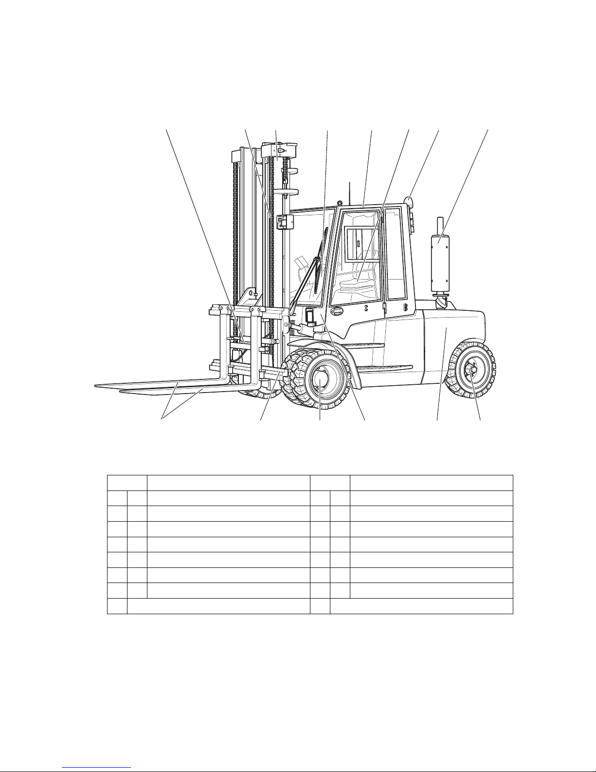
2 Assemblies and Functional Description
2.1 Assembly Overview
6
3
14 13 12 910
12
4
5
78
11
Item Description Item Description
1 o Fork adjustment 8 t Exhaust pipe
2 t Load chains 9 t Steer axle
3 t Mast 10 t Counterweight
4 t Steering column 11 t Illumination
5 t Cab 12 t Drive
6 t Driver's seat 13 t Fork carriage
7 o Beacon 14 t Fork tines
t = Standard equipment o = Optional equipment
Page 16

17
11.14 E N
2.2 Functional Description
Chassis and superstructure
A rigid chassis which protects the units and controls, provides the truck with
maximum static safety. A wide opening cab (5) facilitates service and maintenance
work. The hydraulic oil reservoir is integrated on the right-hand side and the fuel tank
on the opposite side of the chassis. The vertical, free standing front exhaust pipe (8)
is positioned much higher than is common. It prevents vibrations and sound saves
from being transferred and exhaust gases from penetrating into the operator position.
Operator position
The operator position is articulating, which cushions vibrations and noise. Non-slip
steps and a handle on the cab post ensure easy entry and exit. The driver is protected
by the cab (5). To adapt the seat position, the driver can adjust the seat and steering
head both vertically and horizontally. The accelerator pedal and brake pedal are of
"automotive" design.
Steering
The steer cylinder of the hydrostatic steering is integrated in the steer axle (9) and is
controlled by the power steering. The steer axle is fully floating in the chassis to
ensure excellent grip even on non-level surfaces.
Wheels
All wheels are located within the truck geometry. A choice of pneumatic or
superelastic tyres are available.
Diesel engine
Quiet-running, water-cooled diesel engines featuring high performance and low
consumption with very clean fuel combustion under all operating conditions ensure
soot values are below the limit of visibility. An additional particle filter (o) ensures
very low exhaust levels.
LPG engine
Quiet running, water-cooled four-stroke engines featuring high performance and low
consumption. Petrol engines with very low residual exhaust levels are used. A 3-way
catalytic converter ensures very low exhaust levels.
Electrical System
12-volt system with 3-phase alternator. A repeat start block prevents malfunctions
when the truck is powered up. For diesel engines, a rapid pre-heat system is installed;
LPG motors have an electronic ignition system for rapid and trouble-free engine
starting. The key switch is used to start and stop the engine.
Page 17

11.14 E N
18
Drive System
A power shift gear with radiator and torque converter is flanged directly to the engine.
This transfers the force to the drive axle (12).
The travel direction lever, either on the steering column or optionally on the multi-task
handle, controls forward/reverse travel and the neutral position.
Brakes
The brake pedal activates the laminated brakes hydraulically. The parking brake is
switched on and off by pressing the parking brake button in the multifunction display.
It acts mechanically on the brake disc of the cardan shaft.
Hydraulic System
All operations can be performed sensitively, proportionally and simultaneously.
Hydraulic functions are controlled by a servo hydraulic controller. Control is possible
via single lever (SOLO-PILOT) or multi-task lever (MULTI-PILOT).
Mast
Two or three-stage masts, optionally with free lift function; narrow mast sections
ensure excellent visibility of the fork tines and attachments. Fork carriages and lift
frames run on lubricating support rollers.
Attachments
The trucks can be optionally fitted with mechanical and hydraulic attachments.
Page 18

19
11.14 E N
3 Technical Specifications
All technical details refer to standard trucks.
Values indicated with *) may vary, depending on the
types of equipment used (e.g. mast, cabin, tyres etc.).
Z The technical specifications comply with the German "Industrial Truck Data Sheet"
Guidelines.
Technical modifications and additions reserved.
3.1 Performance data
DFG 660-690
1)
for vertical mast.
2)
The values shown represent the maximum gradeability to overcome short
differences in height and surface unevenness (surface edges). The truck must not
operate on inclines of more than 15%.
Component 660 670 680 690
QCapacity
1)
6000 7000 8000 9000 kg
C Load centre distance 600 600 600 600 mm
Travel speed * with /
without load
22.4/22.5 22.4/22.6 22.4/22.5 22.4/22.6 km/h
Lift speed with / without
load
0.50/0.60 0.40/0.60 0.40/0.60 0.40/0.60 m/s
Lowering speed with /
without load
0.60/0.36 0.60/0.36 0.60/0.36 0.60/0.36 m/s
Gradeability
2)
with / without load
30.3/32.0 28.7/31.0 27.1/31.0 24.6/28.0 %
Tow force
with/without load
49.5/49.5 49.5/49.5 49.5/49.5 49.5/49.5 kN
Acceleration* with /
without load to 15 m
6.0/5.0 6.0/5.0 6.0/5.0 7.0/6.0 sec
Available working
pressure
for attachments
160 160 160 160 bar
Oil flow
for attachments
80 80 80 80 l/min
Page 19

11.14 E N
20
DFG S80-S90
1)
for vertical mast.
2)
The values shown represent the maximum gradeability to overcome short
differences in height and surface unevenness (surface edges). The truck must not
operate on inclines of more than 15%.
Component S80 S90
Q Capacity
1)
8000 9000 kg
C Load centre distance 900 900 mm
Travel speed *
with / without load
22.3/22.6 22.3/22.6 km/h
Lift speed
with / without load
0.40/0.60 0.40/0.60 m/s
Lowering speed
with / without load
0.60/0.36 0.60/0.36 m/s
Gradeability
2
with / without load
21.5/25.0 20.9/24.0 %
Tow force with / without load 49.5/49.5 52.9/52.9 kN
Acceleration time *
with / without load to 15 m
7.0/6.0 7.0/6.0 sec
Available working pressure
for attachments
160 160 bar
Oil flow for attachments 80 80 l/min
Page 20

21
11.14 E N
TFG 660-690
1)
for vertical mast.
2)
The values shown represent the maximum gradeability to overcome short
differences in height and surface unevenness (surface edges). The truck must not
operate on inclines of more than 15%.
Component 660 670 680 690
QCapacity
(1
6000 7000 8000 9000 kg
C Load centre distance 600 600 600 600 mm
Travel speed * with /
without load
22.4/22.6 22.4/22.6 22.4/22.6 22.4/22.6 km/h
Lift speed
with / without load
0.40/0.48 0.40/0.48 0.40/0.48 0.40/0.48 m/s
Lowering speed
w / w.o. load
0.60/0.48 0.60/0.36 0.60/0.36 0.60/0.36 m/s
Gradeability
(2
with / without load
27.5/30.0 27.5/30.0 26.5/30.0 23.0/27.0 %
Tow f o r ce
with / without load
45.6/45.6 45.6/45.6 45.6/45.6 45.6/45.6 kN
Acceleration * with /
without load to 15 m
6.0/5.0 6.0/5.0 6.0/5.0 7.0/6.0 sec
Available working
pressure
for attachments
160 160 160 160 bar
Oil flow
for attachments
80 80 80 80 l/min
Page 21

11.14 E N
22
TFG S80-S90
1)
for vertical mast.
2)
The values shown represent the maximum gradeability to overcome short
differences in height and surface unevenness (surface edges). The truck must not
operate on inclines of more than 15%.
Component S80 S90
Q Capacity 8000 9000 kg
C Load centre distance 900 900 mm
Travel speed *
with / without load
22.4/22.6 22.4/22.6 km/h
Lift speed
with / without load
0.40/0.48 0.40/0.48 m/s
Lowering speed
with / without load
0.60/0.36 0.60/0.36 m/s
Gradeability*
with / without load
20.2/23.0 17.6/20.0 %
Tow f or ce
with / without load
45.6/45.6 45.6/45.6 kN
Acceleration time *
with / without load to 15 m
7.0/6.0 7.0/6.0 sec
Available working
pressure
for attachments
160 160 bar
Oil flow
for attachments
80 80 l/min
Page 22

23
11.14 E N
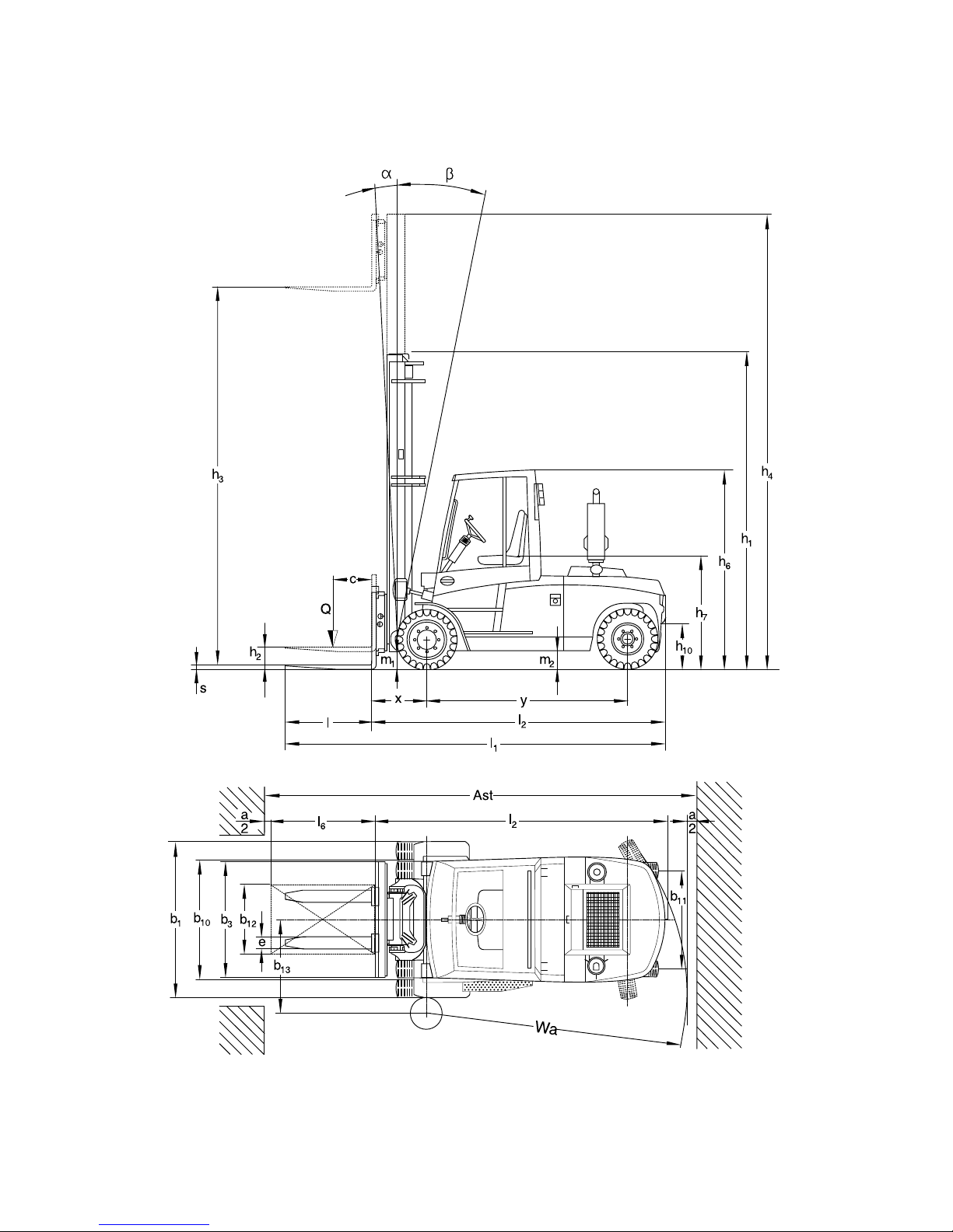
3.2 Dimensions
DFG 660-690
*) The data listed in the table corresponds to the standard version.
Model 660 670 680 690
a/2 Safety distance 100 100 100 100 mm
h
1
Collapsed height* 2710 2710 3010 3160 mm
h
3
Lift* 3600 3600 3600 3600 mm
h
4
Extended height* 4510 4510 4810 4960 mm
h
6
Overhead guard
height*
2705 2705 2705 2705 mm
h7Seat height* 1600 1600 1600 1600 mm
h
10
Coupling height 500 500 500 500 mm
Į
Mast tilt, fwd.* 6 6 6 6 °
ȕ
Mast tilt, back* 9 9 9 9 °
l1Length, including
forks*
4760 4770 4880 5035 mm
l
2
Length, including fork
shank*
3560 3570 3680 3835 mm
b1Overall width* 1820 2002 2002 2100 mm
s/e/l Fork dimensions* 60/150/
1200
60/150/
1200
70/150/
1200
70/150/
1200
mm
m
1
Ground clearance,
laden, below mast*
230 230 230 230 mm
m2Ground clearance
centre wheelbase*
250 250 250 250 mm
Fork carriage ISO
2328 class / type A, B
4 A4 A4 A4 Amm
b
3
Fork carriage width 1800 1800 2000 2100 mm
Ast Working aisle width for
pallets 800 x 1200
lengthways
5320 5330 5440 5745 mm
Ast Working aisle width for
pallets 1000 x 1200
traverse
5120 5130 5240 5545 mm
Wa Turning radius 3250 3250 3350 3650 mm
b
13
Smallest turning
radius
1270 1270 1320 1390 mm
x Load distance* 680 680 700 700 mm
c Load centre of gravity 600 600 600 600 mm
y Wheelbase 2295 2295 2395 2545 mm
Page 23

11.14 E N
24
DFG S80-S90
*) The data listed in the table corresponds to the standard version.
TFG 660-690
Model S80 S90
a/2 Safety distance 100 100 mm
h
1
Collapsed height* 3160 3310 mm
h
3
Lift* 3600 3600 mm
h4Extended height* 4960 5110 mm
h
6
Overhead guard
height*
2705 2705 mm
h7Seat height* 1600 1600 mm
h10Coupling height 500 500 mm
Į
Mast tilt, fwd.* 6 6 °
ȕ
Mast tilt, back* 9 9 °
l
1
Length, including
forks*
5640 5840 mm
l2Length, including fork
shank*
3840 4040 mm
b
1
Overall width* 2150 2150 mm
s/e/l Fork dimensions* 70/180/
1800
70/180/
1800
mm
m1Ground clearance,
laden, below mast*
230 230 mm
m
2
Ground clearance
centre wheelbase*
250 250 mm
Fork carriage ISO
2328 class / type A, B
4 A 4 A mm
b
3
Fork carriage width 2100 2100 mm
Ast Working aisle width for
pallets 800 x 1200
lengthways
5745 5995 mm
Ast Working aisle width for
pallets 1000 x 1200
traverse
5545 5795 mm
Wa Turning radius 3900 3900 mm
b
13
Smallest turning
radius
1490 1490 mm
x Load distance* 700 700 mm
c Load centre of gravity 900 900 mm
y Wheelbase 2545 2745 mm
Type 660 670 680 690
a/2 Safety distance 100 100 100 100 mm
Page 24

25
11.14 E N
*) The data listed in the table corresponds to the standard version.
TFG S80-S90
h
1
Collapsed height* 2710 2710 3010 3160 mm
h
3
Lift* 3600 3600 3600 3600 mm
h
4
Extended height* 4510 4510 4810 4960 mm
h
6
Overhead guard
height*
2705 2705 2705 2705 mm
h
7
Seat height* 1600 1600 1600 1600 mm
h
10
Coupling height 500 500 500 500 mm
Į
Mast tilt, fwd.* 6 6 6 6 °
ȕ
Mast tilt, back* 9 9 9 9 °
l1Length, including
forks*
4860 4870 4980 5135 mm
l
2
Length, including fork
shank*
3660 3670 3780 3935 mm
b1Overall width* 1820 2002 2002 2150 mm
s/e/l Fork dimensions* 60/150/
1200
60/150/
1200
70/150/
1200
70/150/
1200
mm
m
1
Ground clearance,
laden, below mast*
230 230 230 230 mm
m2Ground clearance
centre wheelbase*
235 250 250 250 mm
Fork carriage ISO
2328 class / type A, B
4 A4 A4 A4 Amm
b
3
Fork carriage width 1800 1800 2000 2100 mm
Ast Working aisle width for
pallets 800 x 1200
lengthways
5420 5430 5640 5895 mm
Ast Working aisle width for
pallets 1000 x 1200
traverse
5220 5230 5440 5695 mm
Wa Turning radius 3350 3350 3550 3800 mm
b
13
Smallest turning
radius
1320 1320 1370 1440 mm
x Load distance* 680 680 700 700 mm
c Load centre of gravity 600 600 600 600 mm
y Wheelbase 2395 2395 2495 2645 mm
Component S80 S90
a/2 Safety distance 100 100 mm
h
1
Mast height retracted* 3160 3310 mm
h
3
Lift* 3600 3600 mm
h
4
Mast height extended* 4960 5110 mm
Type 660 670 680 690
Page 25

11.14 E N
26
*) The data listed in the table corresponds to the standard version.
h
6
Overhead guard
height*
2705 2720 mm
h
7
Seat height* 1600 1600 mm
h
10
Coupling height 500 500 mm
Į
Mast tilt, fwd.* 6 6 °
ȕ
Mast tilt, back* 9 9 °
l
1
Length, including
forks*
5740 5740 mm
l2Length, including fork
shank*
3940 3940 mm
b1Overall width* 2150 2150 mm
s/e/l Fork dimensions* 70/180/
1800
70/180/
1800
mm
m
1
Ground clearance,
laden, below mast*
240 240 mm
m
2
Ground clearance
centre wheelbase*
240 240 mm
Fork carriage ISO
2328 class / type A, B
4 A 4 A mm
b3Fork carriage width 2100 2100 mm
Ast Aisle width for pallets
800 x 1200
lengthways
5895 5895 mm
Ast Working aisle width for
pallets 1000 x 1200
traverse
5695 5695 mm
Wa Turning radius 3800 3800 mm
b
13
Smallest turning
radius
1440 1440 mm
x Load distance* 700 700 mm
c Load centre of gravity 900 900 mm
y Wheelbase 2645 2645 mm
Component S80 S90
Page 26
27
11.14 E N
Page 27

11.14 E N
28
3.3 Weights
Z All dimensions in kg.
DFG 660-690
*) The data listed in the table corresponds to the standard version.
DFG S80-S90
*) The data listed in the table corresponds to the standard version.
TFG 660-690
*) The data listed in the table corresponds to the standard version.
TFG S80-S90
*) The data listed in the table corresponds to the standard version.
660 670 680 690
Net weight* 10500 11400 12400 14000
Axle loading, unladen
load front / rear*
5000/5500 5500/5900 6000/6400 6800/7200
Axle loading, laden front /
rear*
14900/1600 16400/2000 18100/2300 20500/2500
S80 S90
Net weight* 14400 15500
Axle loading, unladen
load front / rear*
7200/7200 7800/7700
Axle loading, laden front /
rear*
20400/2000 22500/2000
660 670 680 690
Net weight* 10970 11570 12700 14200
Axle loading, unladen
load front / rear*
5360/5610 5660/5910 5800/6100 6900/7300
Axle loading, laden front /
rear*
14810/2160 16670/1900 18600/2100 20700/2500
S80 S90
Net weight* 14600 15200
Axle loading, unladen
load front / rear*
7300/7300 7500/7700
Axle loading, laden front /
rear*
20100/2500 22100/2100
Page 28

29
11.14 E N
3.4 Mast versions
Z All dimensions in mm.
Mast chart
V D I 3 5 9 6
Description
Lift h
3
Free lift
h
2
Retracted
height h
1
Extended
height h
4
Weight
(kg)
660/670 660/670
ZT
3600 0 2710 4510 2080
4000 0 2910 4910 2140
4500 0 3160 5410 2240
5000 0 3410 5910 2335
5500 0 3660 6410 2460
6000 0 3910 6910 2585
6500 0 4160 7410 2735
ZZ
3600 1800 2875 4675 2278
4000 2000 3075 5075 2350
4500 2250 3325 5675 2422
5000 2500 3575 6075 2542
5500 2750 3825 6575 2652
6000 3000 4075 7075 2772
6500 3300 4325 7575 2892
DZ
4500 1500 2585 5585 2671
5000 1667 2752 6086 2754
5500 1833 2918 6586 2837
6000 2000 3085 7086 2920
6500 2167 3252 7586 3045
7000 2333 3418 8086 3191
7500 2500 3585 8586 3295
8000 2667 3752 9086 3397
Page 29

11.14 E N
30
Special trucks are not included in this overview.
Mast chart
V D I 3 5 9 6
Description
Lift h
3
Free lift
h
2
Retracted
height h
1
Extended
height h
4
Weight
(kg)
680 680
ZT
3600 0 3010 4810 2180
4000 0 3210 5210 2261
4500 0 3460 5710 2360
5000 0 3710 6210 2485
5500 0 3960 6710 2610
6000 0 4210 7210 2757
6500 0 4460 7710 2910
ZZ
3600 1800 3025 4825 2326
4000 2000 3225 5225 2350
4500 2250 3475 5725 2422
5000 2500 3725 6225 2604
5500 2750 3975 6725 2724
6000 3000 4225 7225 2847
6500 3300 4475 7725 2964
DZ
4500 1500 2735 5736 2733
5000 1667 2902 6236 2816
5500 1833 3068 6736 2900
6000 2000 3235 7236 3024
6500 2167 3402 7736 3170
7000 2333 3568 8236 3274
7500 2500 3735 8736 3377
8000 2667 3902 9236 3459
Page 30

31
11.14 E N
DFG/TFG 690-S90
Mast chart
V D I 3 5 9 6
Description
Lift h
3
Free lift
h
2
Collapsed
height h
1
Extended
height h
4
Weight
(kg)
690/S80 690/S80
ZT
3600 0 3160 4960 2240
4000 0 3360 5360 2310
4500 0 3610 5860 2435
5000 0 3860 6360 2560
5500 0 4110 6860 2710
6000 0 4360 7360 2860
6500 0 4610 7860 2985
ZZ
3600 1800 3175 4975 2374
4000 2000 3375 5375 2446
4500 2250 3625 5875 2556
5000 2500 3875 6375 2676
5500 2750 4125 6875 2796
6000 3000 4375 7375 2916
6500 3300 4625 7875 3036
DZ
4500 1500 2885 5886 2796
5000 1667 3052 6386 2879
5500 1833 3218 6886 3004
6000 2000 3385 7386 3149
6500 2167 3552 7886 3253
7000 2333 3718 8386 3357
7500 2500 3885 8886 3439
8000 2667 4052 9386 3522
Mast chart
V D I 3 5 9 6
Description
Lift h
3
Free lift
h
2
Collapsed
height h
1
Extended
height h
4
Weight
(kg)
S90 S90
ZT
3600 0 3310 5110 2285
4000 0 3510 5510 2385
4500 0 3760 6010 2510
5000 0 4010 6510 2635
5500 0 4260 7010 2810
6000 0 4510 7510 2935
6500 0 4760 8010 3060
Page 31

11.14 E N
32
Special trucks are not included in this overview.
ZZ
3600 1800 3325 5125 2422
4000 2000 3525 5525 2518
4500 2250 3775 6025 2628
5000 2500 4025 6525 2748
5500 2750 4275 7025 2868
6000 3000 4525 7525 2988
6500 3300 4775 8025 3108
DZ
4500 1500 3035 6036 2858
5000 1667 3202 6536 2983
5500 1833 3368 7036 3128
6000 2000 3535 7536 3232
6500 2167 3702 8036 3336
7000 2333 3868 8536 3418
7500 2500 4035 9036 3501
8000 2667 4202 9536 3574
Mast chart
V D I 3 5 9 6
Description
Lift h
3
Free lift
h
2
Collapsed
height h
1
Extended
height h
4
Weight
(kg)
S90 S90
Page 32

33
11.14 E N
3.5 Tyre type
WARNING!
The use of tyres that do not match the manufacturer's specifications can result
in accidents.
The quality of tyres affects the stability and performance of the truck.
Uneven wear affects the truck's stability and increases the stopping distance.
X
When replacing tyres make sure the truck is not skewed.
X
Always replace tyres in pairs, i.e. left and right at the same time.
Z When replacing rims and tyres fitted at the factory, only use the manufacturer’s
original spare parts. Otherwise the manufacturer’s specifications cannot be
ensured. If you have any queries contact the manufacturer's customer service
department.
DFG/TFG 660-690
Model DFG/TFG
660 670 680 690
Front
tyres
SE* 355/65 - 15 8.25 - 15 8.25 - 15 300 - 15
Pneumatic*
355/65 - 15
18 PR
8.25 - 15
18 PR
8.25 - 15
18 PR
300 - 15
18 PR
Tyre pressure bar 10 10 10 10
Torque Nm 650 650 650 650
Rear
tyres
SE* 8.25 - 15 8.25 - 15 8.25 - 15 300 - 15
Pneumatic*
8.25 - 15
18 PR
8.25 - 15
18 PR
8.25 - 15
18 PR
300 - 15 18
PR
Tyre pressure bar 10 10 10 10
Torque Nm 450 450 450 450
Page 33

11.14 E N
34
DFG/TFG S80-S90
*) The models listed in the table correspond to the standard version. Other tyres can
be used depending on the truck's equipment.
Model DFG/TFG
S80 S90
Front
tyres
SE* 300 - 15 300 - 15
Pneumatic*
300 - 15
18 PR
300 - 15
18 PR
Tyre pressure bar 10 10
Torque Nm 650 650
Rear
tyres
SE* 300 - 15 300 - 15
Pneumatic*
300 - 15
18 PR
300 - 15
18 PR
Tyre pressure bar 10 10
Torque Nm 450 450
Page 34

35
11.14 E N
3.6 Engine Data
DFG 660-680
DFG 690-S90
TFG 660-680
TFG 690-S90
Model DFG 660 DFG 670 DFG 680
Cylinders/cubic capacity 4/4400 4/4400 4/4400 cm³
Rated speed (without load) 2200 2200 2200 rpm
Idle speed 850 850 850 rpm
Engine output 91 91 91 kW
Fuel consumption
60 VDI duty cycles/h
7.7 8.1 8.5 l/h [kg/h]
Model DFG 690 DFG S80 DFG S90
Cylinders/cubic capacity 4/4400 4/4400 6/6600 cm³
Rated speed (without load) 2200 2200 2200 rpm
Idle speed 850 850 850 rpm
Engine output 91 91 90 kW
Fuel consumption
60 VDI duty cycles/h
8.8 8.8 10.3 l/h [kg/h]
Model TFG 660 TFG 670 TFG 680
Cylinders/cubic capacity 8/5700 8/5700 8/5700 cm³
Rated speed (without load) 2200 2200 2200 rpm
Idle speed 850 850 850 rpm
Engine output 85 85 85 kW
Fuel consumption
60 VDI duty cycles/h
8 8.5 8.9 l/h [kg/h]
Model TFG 690 TFG S80 TFG S90
Cylinders/cubic capacity 8/5700 8/5700 8/5700 cm³
Rated speed (without load) 2200 2200 2200 rpm
Idle speed 850 850 850 rpm
Engine output 85 85 85 kW
Fuel consumption
60 VDI duty cycles/h
10.2 10.2 10.7 l/h [kg/h]
Page 35

11.14 E N
36
3.7 EN norms
Noise emission level
– DFG 660-690, S80: 73 dB (A)*
– DFG S90: 70 dB (A)*
– TFG: 71 dB(A)*
*+/- 4 dB(A) depending on the truck's equipment
in accordance with EN 12053 as harmonised with ISO 4871.
Z The noise emission level is calculated in accordance with standard procedures and
takes into account the noise level when travelling, lifting and when idle. The noise
level is measured at the level of the driver's ear.
Vibration
in accordance with EN 13059.
Z The vibration acceleration acting on the body in the operating position is, in
accordance with standard procedures, the linearly integrated, weighted
acceleration in the vertical direction. It is calculated when travelling over thresholds
at constant speed (standard truck version). These recordings were taken on a
single occasion and must not be confused with the human vibrations of the "2002/
44/EC/Vibrations" operator directive. The manufacturer offers a special service to
measure these human vibrations, see "Human vibration measurement" on
page 198.
Z The vibration that is characteristic for vibrations of the body cannot be used to
determine the actual load caused by vibrations during operation. That depends on
the operating conditions (condition of the travel routes, method of operation, etc.)
and should therefore be determined on site at a suitable location. Hand/arm
vibration must always be determined without exception, even if the values do not
indicate any hazard at all, as in this case.
Whole-body vibration
Motor type Vibration Uncertainty
TFG 1.0 m/s
2
0.2 m/s
2
DFG S90 0.9 m/s
2
0.2 m/s
2
DFG 660-690, S80 1.3 m/s
2
0.2 m/s
2
Hand/arm vibration
Vibration <2.5 m/s
2
Page 36

37
11.14 E N
Electromagnetic compatibility (EMC)
The manufacturer confirms that the truck adheres to the limits for electromagnetic
emissions and resistance as well as the static electricity discharge test in accordance
with EN 12895 as well as the standardised instructions contained therein.
Z No changes to electric or electronic components or their arrangement may be
made without the written agreement of the manufacturer.
WARNING!
Medical equipment can be damaged by non-ionised radiation
Electrical equipment on the truck emitting non-ionised radiation (e.g. wireless data
transmission) can affect operators' medical equipment (pacemakers, hearing aids
etc.) and result in malfunctions. Consult with a doctor or the medical equipment
manufacturer to clarify whether it can be used near the industrial truck.
3.8 Conditions of use
Ambient temperature
– operating at -20 to 40°C
Z Special equipment and authorisation are required if the truck is to be used
continually in conditions of extreme temperature or condensing air humidity
fluctuations.
3.9 Electrical requirements
The manufacturer certifies compliance with the requirements for the design and
manufacture of electrical equipment, according to EN 1175 "Industrial Truck Safety Electrical Requirements", provided the truck is used according to its purpose.
Page 37

11.14 E N
38
4 Identification points and data plates
Z Warnings and notices such as capacity charts, strap points and data plates must
be legible at all times. Replace if necessary.
XXXXXX
xxx xxxxxx
1
0
21
24
35
27
22
29
15
15
16 17 1918
36
20
26
28
33
31
39 40 42
38
23
30
15
4137
25
34
32
25
19
Page 38

39
11.14 E N
Item Component
15 Attachment points for loading by crane (o)
16 Read operating instructions
17 Wear seat belt
18 Test plaque (o)
19 Hot surface warning
20 Trailer coupling
21 Capacity plate
22 Tipover hazard
23 No passengers
24 Do not drive or tilt the mast forward with a load raised
25 Turn the exhaust pipe back before tilting the cab
26 Air pressure
27 Do not stand on load handler / Do not stand under load handler / Risk of
trapping when mast extended
28 Hydraulic oil
29 Jack contact points
30 Emergency exit
31 Battery main switch
32 Warning
33 Coolant notice
34 Noise level
35 Truck data plate
36 Fuel
37 Lift load cushioning (o)
38 Fire extinguisher (o)
39 Add engine oil
40 Windscreen fluid
41 Coolant
42 Check engine oil
Page 39

11.14 E N
40
4.1 Data plate
Z For queries regarding the truck or ordering spare parts always quote the truck serial
number (44).
43 44 4645
52
49
51
48
47
50
Item Component Item Component
43 Type 48 Year of manufacture
44 Serial number 49 Load centre distance (mm)
45 Rated capacity (kg) 50 Net weight in kg
46 Output 51 Manufacturer
47 Option 52 Manufacturer's logo
Page 40

41
11.14 E N
4.2 Truck capacity plate
CAUTION!
Accident risk from fork replacement
If you replace the forks with ones that differ from the originals, the capacity will
change.
X
When replacing the forks you must attach an additional capacity plate to the truck.
X
Trucks supplied without forks are given a capacity plate for standard forks (length:
1150 mm).
The capacity plate (21) gives the capacity (Q in kg) of the truck for a vertical mast.
The maximum capacity is shown as a table with a given load centre of gravity D (in
mm) and the required lift height H (in mm).
The capacity plate (21) of the truck indicates the truck's capacity with the forks as
originally supplied.
Example of how to calculate the maximum capacity:
With a load centre distance D of 700 mm and a maximum lift height h
3
of 5000 mm.
the max. capacity Q is 6940 kg.
Lift height restriction
The arrow shaped markings (53 and
54) on the inner and outer masts show
the operator when the prescribed lift
limits have been reached.
6960
7470
8340
6460
6940
7740
5660
6080
6770
6000
5000
4000
600 700 900
21
53 54
Page 41

11.14 E N
42
4.3 Attachment capacity plate
The attachment capacity plate is next to the truck's capacity plate and gives the
truck’s capacity Q (in kg) in conjunction with the respective attachment. The serial
number for the attachment indicated on the capacity plate must match the data plate
of the attachment.
4.4 Jack attachment point
The "Jack contact point" decal (29) indicates
where the truck may be lifted and jacked up.
5 Stability
The truck's stability has been tested according to latest technological standards.
These take into account the dynamic and static tipover forces that can occur if used
correctly.
Stability can also be affected by the following factors:
– Tyre type
–Mast
– Attachment
– Transported load (size, weight and centre of gravity)
WARNING!
Loss of stability can cause accidents
Changing the components can alter the stability.
29
Page 42

43
11.14 E N
C Transport and Commissioning
1 Transport
Transport can be carried out in two different ways, depending on the height of the
mast and the local conditions.
– Vertically, with the mast assembled (for low heights)
– Vertically, with the mast dismantled (for large heights), all mechanical connections
and hydraulic lines between the basic truck and the mast separated.
2 Truck laden
2.1 Centre of gravity of the truck
WARNING!
An altered centre of gravity can result in tipovers when cornering.
The overall centre of gravity can vary depending on the truck's equipment (especially
the mast version).
For trucks without a mast the centre of gravity will move significantly in the direction
of the counterweight.
XDrive carefully and with modified speed to avoid tipping over.
The picture shows the approximate centre of
gravity location.
Page 43

11.14 E N
44
2.2 Lifting the truck by crane
CAUTION!
The mast can get damaged
X
Loading by crane is only intended for the initial transport before the truck is used
for the first time.
X
Loading must be carried out by specially trained staff in accordance with
recommendations contained in Guidelines VDI 2700 and VDI 2703
DANGER!
Crane slings can tear, resulting in accidents
X
Only use crane lifting gear with sufficient capacity.
X
Loading weight = Net weight of truck (+ battery weight for electric trucks).
X
The mast must be tilted back fully.
X
The crane lifting gear on the mast must have a minimum clear length of 2 m.
X
Crane slings should be fastened in such a way that they do not come into contact
with any attachments or the overhead guard when lifting.
XDo not stand under a swaying load.
XThe truck should only be handled by people who are trained in using lifting slings
and tools.
XWear safety shoes when lifting the truck by crane.
XDo not walk into or stand in a hazardous area.
XAlways attach the crane lifting gear to the prescribed strap points and prevent them
from slipping.
Z Truck net weight: see "Data plate" on page 40.
Lifting the truck by crane
Requirements
– Park the truck securely, see "Parking the
truck securely" on page 103.
Procedure
• Secure the crane slings to the attachment
points (55) and (56.
• Raise and load the truck.
• Lower and deposit the truck carefully (see
"Parking the truck securely" on page 103).
• Secure the truck with wedges to prevent it
from rolling away.
This concludes the loading by crane.
56
55
Page 44

45
11.14 E N
2.3 Loading with another industrial truck
DANGER!
Slipping can cause accidents
X
Do not use another Industrial truck to load the truck!
Page 45

11.14 E N
46
3 Securing the truck during transport
WARNING!
Accidental movement during transport
Improper fastening of the truck and mast during transport can result in serious
accidents.
X
Loading must be carried out by specially trained staff in accordance with
recommendations contained in Guidelines VDI 2700 and VDI 2703 In each case
correct measurements must be made and appropriate safety measures adopted.
X
The truck must be securely fastened when transported on a lorry or a trailer.
X
The loading area must have clamp rings and a wooden floor to secure the retaining
wedges.
X
Use wedges to prevent the truck from moving.
X
Use only tensioning belts or tie-down straps or with sufficient strength.
Securing with a mast Securing without a mast
Securing the industrial truck for transport
Requirements
– Position the industrial truck securely on a lorry or trailer, see "Parking the truck
securely" on page 103.
Tools and Material Required
– 2 fastening belts with a tensioner
– Retaining wedges
Procedure
• Secure the truck with the fastening belt (58) at the top cross member of the mast
(55) and the trailer coupling (56) or over the front axle cross member (57) and the
trailer coupling (56).
• Tighten the fastening belts (58) with the tensioner.
The truck is now secured for transport.
58
58
58
58
55
56
57
Page 46

47
11.14 E N
4 Using the Truck for the First Time
Safety Instructions for Assembly and Commissioning
WARNING!
Incorrect assembly can result in accidents
The assembly of the truck at the application site, commissioning and operator training
must only be performed by the manufacturer's customer service representatives who
have been specially trained for these tasks.
X
The hydraulic lines may only be connected to the basic truck / mast interface when
the mast has been properly assembled.
X
Only then can the truck be started.
X
If several trucks have been delivered, make sure that the serial numbers of the load
handlers, masts and basic trucks always match.
Preparing the truck for operation after delivery or transport
Procedure
• Check the equipment is complete.
• Check the engine oil level.
• Check the hydraulic oil level.
• Check the transmission oil level.
• Check the brake fluid level.
• Test the battery connections.
• Check the battery acid level (not for maintenance-free batteries).
The truck can now be started, see "Preparing the Truck for Operation" on page 86.
Page 47

11.14 E N
48
Page 48

49
11.14 E N
D Fuelling the Truck
1 General
1.1 Safety regulations for handling diesel fuel and LPG
WARNING!
An unsecured industrial truck can cause accidents
The truck can suddenly start to move.
X
Switch off the truck securely before filling up or replacing the LPG bottle, see
"Parking the truck securely" on page 103.
WARNING!
Accident risk from ignition
X
Fuels and liquefied petroleum gas can ignite.
X
Smoking, naked flames and other ignition sources are strictly prohibited in the
immediate vicinity when handling fuels and LPG.
XLabels indicating the hazard are must be positioned where they are clearly visible.
XDo not store flammable materials in this area.
XPowder fire extinguisher must be provided within easy reach of the filling area.
XUse only category A, B or C type powder fire extinguishers to fight LPG fires.
XBring any unsealed LPG bottles immediately outside, attach visible markings and
notify the supplier.
Storage and Transport
The diesel and LPG storage and transport devices must comply with statutory
requirements.
If there is no filling point available, the fuel must be stored and transported in clean,
approved containers.
The contents must be clearly indicated on the container.
Page 49

11.14 E N
50
NOTE
Fuel can cause environmental damage
X
Bind any spilled diesel fuel with suitable methods.
X
Then dispose of the diesel and fuel filter in accordance with environmental
regulations.
Fuel filling and LPG bottle replacement personnel
Personnel filling the trucks or replacing LPG bottles must have sufficient knowledge
of the nature of fuels to ensure safe operation.
CAUTION!
Liquid gas can cause frostbite
X
Liquid gas produces frostbite when it comes into contact with bare skin.
X
Avoid direct contact with the skin.
X
Wear gloves.
Filling up LPG containers
LPG containers remain attached to the truck and are filled up at LPG stations. Always
follow the instructions of the tank system and LPG container manufacturer as well as
statutory and local regulations when filling up.
NOTE
Instructions for the safe operation of LPG systems
XAll maintenance and repair work on LPG systems and containers should be carried
out by qualified personnel who have been trained to work on LPG systems.
XThe owner must comply with all legal requirements, technical standards and health
and safety regulations applicable to liquid gas.
XBefore starting work, the operator must check that all accessible components of the
LPG system are in good working order, in accordance with the regulations of the
country of use.
XDo not operate the truck if there is any damage, corrosion, wear or degradation to
individual components of the LPG system.
Page 50

51
11.14 E N
1.2 LPG system relief valve
LPG powered trucks are fitted with a
relief valve. This is located on the rear
cover next to the gas bottle.
– In the event of a fault the pressure in
the gas system is restricted to a
maximum level. The relief valve is
fitted with a plastic cover (59).
– When the valve is activated the plastic
cover comes off, thereby clearly
indicating a fault in the gas system.
– In this case the truck must not be
operated.
– The gas system must be check by
suitably qualified and trained
personnel.
– The operator must check that the plastic cover is in place each time he uses the
truck.
– Models with a liquid gas tank have the
relief valve (61) in the drive
compartment. The relief valve is fitted
with a hose (60) that diverts the LPG if
the relief valve is opened.
– When the valve is activated the plastic
cover comes off, thereby clearly
indicating a fault in the gas system.
– In this event the truck must not be
operated.
– The gas system must be check by
suitably qualified and trained
personnel.
– The user must check that the plastic
cover is present each time he uses the
truck.
DANGER!
Danger from escaping liquid gas.
Liquid gas can escape from faulty gas hoses.
XUse only gas bottles with an integrated line break safety valve.
XThe gas bottle connection is also fitted with a line break safety valve which prevents
the gas from escaping accidentally during operation.
XWhen replacing, always use a gas bottle connection with an integrated line break
safety valve.
59
6061
Page 51

11.14 E N
52
2 Adding diesel
CAUTION!
Air in the fuel system will result in malfunctions.
X
Never allow the fuel tank to run dry.
2.1 Fuelling
WARNING!
Diesel fuel can be hazardous
X
Diesel fuel can cause irritation if it comes into contact with the skin. Rinse any
affected areas thoroughly.
X
If it comes into contact with the eyes rinse them immediately with flowing water and
call for a doctor.
X
Wear safety gloves when handling diesel fuels.
NOTE
XFuelling must always be performed in designated areas by trained and authorised
personnel.
NOTE
XCapacity: DFG 660-690 = 125 l.
XUse only diesel in accordance with DIN 590 or DIN 51628 with a cetane rating
above 51.
2.1.1 Fuelling the tank system
Procedure
• Park the truck securely before fuelling,
see "Parking the truck securely" on
page 103.
• Unscrew the tank cap (62).
• Insert the pump nozzle into the open
tank filler neck.
• Add the fuel.
• Do not overfill the tank.
• Tighten the cap (62) back on after
fuelling.
Fuelling is now complete.
62
Page 52

53
11.14 E N
The fuel gauge (63) indicates the fuel level.
NOTE
X
Never allow the fuel tank to run dry. Air
in the fuel system will result in
malfunctions.
2.2 Fuelling with fuel containers
Procedure
• Unscrew the filler cap (62) and open the
fuel container.
• Fit the spout onto the fuel container.
• Insert the spout into the open tank filler
neck.
• Make sure the fuel container and spout
are connected tightly to each other.
• Raise the fuel container carefully and
slowly add the diesel.
• Do not overfill the tank.
• Screw the cap (62) back on tightly after
fuelling.
Fuelling is now complete.
63
62
Page 53

11.14 E N
54
3 LPG containers
Z Only use liquid gas that complies with DIN 51622 or comparable national
regulations.
3.1 LPG bottles
DANGER!
Risk of explosion
X
The LPG bottle must only be replaced at designated areas by trained and
authorised personnel.
CAUTION!
Using unsuitable LPG bottles can cause accidents.
X
Use only approved LPG bottles.
X
The LPG bottle must always rest on an engaged bottle holder so that the hose
connection of the shutoff valve is facing vertically down.
XFor bottle types of other countries note the national regulations.
XNote the indications and markings on the LPG bottle.
3.1.1 Using an LPG bottle
Replace the LPG bottle
Procedure
• Park the truck securely before replacing
the LPG bottle, see "Parking the truck
securely" on page 103
• Close the shut-off valves (64) securely.
• Start the motor and allow the LPG system
to run empty in neutral.
64
Page 54

55
11.14 E N
Remove the LPG bottle
CAUTION!
The connection has a left thread
Procedure
• The LPG bottle console is released with
the finger screw (65).
• Unfold the console (66) as far as the stop.
• Unscrew the union nut (68).
• Remove the hose (60) and immediately
screw the valve cap onto the empty LPG
bottle.
• Loosen the toggle-type fastener with the
handle (67).
• Carefully remove the LPG bottle from the
bracket and place it down securely.
Inserting a new LPG bottle
Procedure
• Insert the LPG bottle into the bracket
• Align the hose connection downwards.
• Clamp the toggle-type fastener with the
handle (67).
• Unscrew the valve cap.
• Fit the hose (60) in accordance with
instructions.
• Carefully open the shut-off valve (64).
• Check the hose connection for leaks using
a foam-forming agent.
The replacement is now complete.
65
66
67
6864606864
Page 55

11.14 E N
56
3.1.2 Operating the Twin Bottle System and Liquid Gas Tank
Changing the LPG Supply
Procedure
Z The (71) switch controls the release of the LPG bottle
or tank.
• Open the shut-off valves (64) of both LPG bottles by
turning anticlockwise.
• Apply the (71) switch.
• The left LPG bottle (69) is activated by the middle
switch position.
• The right LPG bottle (70) is activated by the lower
switch position.
• Close the LPG bottles and open the LPG tank by
applying the top switch position.
LPG supply changed.
S4
S7 S8 S24
S12 S13 S15
S20 S26 S30
64
71
69 70
Page 56

57
11.14 E N
3.2 Liquid gas tank
The filling valve (72) is located on the left side of the truck.
Filling refillable liquid gas tanks
DANGER!
Risk of explosion
X
Fuelling must always be performed in
designated areas by trained and
authorised personnel.
Requirements
– Park the truck securely (see "Parking the
truck securely" on page 103).
– Note all guidelines and regulations
concerning the filling of LPG bottles on the
LPG pump.
Procedure
• Unscrew the tank cap (62).
• Lock the filling adapter of the tank system in
place on the filling valve (72).
• Enabling filling on the tank system
Z The integrated filling stop valve prevents
the tank from overfilling.
• When the filling process is complete,
release the filling adapter of the filling system from the filling valve (72).
• Screw on the tank cap (62).
Z The level of the tank is shown by the fuel indicator.
62
72
Page 57

11.14 E N
58
4 Fuel level indicator
4.1 Display unit
The level indicator (63) shows the capacity
of the tank.
63
Page 58

59
11.14 E N
E Operation
1 Safety Regulations for the Operation of the
Forklift Truck
Driver authorisation
The truck may only be used by suitably trained personnel, who have demonstrated to
the proprietor or his representative that they can drive and handle loads and have
been authorised to operate the truck by the proprietor or his representative.
Operator’s rights, responsibilities and rules of conduct
The driver must be informed of his duties and responsibilities and be instructed in the
operation of the truck and shall be familiar with the operating instructions. Safety
shoes must be worn on pedestrian-operated trucks.
Unauthorised use of truck
The operator is responsible for the truck during the time it is in use. The operator must
prevent unauthorised persons from driving or operating the truck. Do not carry
passengers or lift other people.
Damage and faults
The supervisor must be informed immediately of any damage or faults to the truck or
attachment. Trucks which are unsafe for operation (e.g. wheel or brake problems)
must not be used until they have been rectified.
Repairs
The operator must not carry out any repairs or alterations to the truck without
authorisation and the necessary training to do so. The operator must never disable or
adjust safety mechanisms or switches.
Page 59

11.14 E N
60
Hazardous area
WARNING!
Risk of accidents/injury in the hazardous area of the truck
A hazardous area is defined as the area in which people are at risk due to travel or
lifting operations of the truck, its load handler or the load. This also includes the area
within reach of falling loads or lowering/falling operating equipment.
X
Instruct unauthorised persons to leave the hazardous area.
X
In case of danger to third parties, give a warning signal in good time.
X
If unauthorised persons are still within the hazardous area, stop the truck
immediately.
WARNING!
Falling objects can cause accidents
Falling objects can injure the operator while the truck is being operated.
X
The operator must remain within the protected area of the overhead guard while
the truck is being operated.
Safety devices, warning signs and warning instructions
Safety devices, warning signs (see "Identification points and data plates" on page 38)
and warning instructions in the present operating instructions must be strictly
observed.
Page 60

61
11.14 E N
2 Displays and Controls
2.1 Multi-task switch
Item Control /
Display
Function
73 Multi-task switch t
– Travel function switch – Sets automatic gear shifting
– Travel direction
switch
– Selects travel direction / neutral position
t
= Standard equipment
o
= Optional equipment
73
74
Einzelpedalsteuerung
76 75
to
Page 61

11.14 E N
62
74 Multi-task switch
t
– Travel direction
indicator
– Switches the travel direction indicator on
and off
– Dipped lights/main
beam
– Switch spot lights from dipped lights to
main beam
– Windscreen wiper – Switches the windscreen wiper on and off
– Switches interval speed on and off
– Windscreen washing
system
– Switches windscreen washing system on
and off
– Horn – Activates an audible warning
76 Brake pedal
t
When activated, causes the truck to brake to
a halt immediately.
75 Accelerator pedal
t
Infinite travel speed control.
Item Control /
Display
Function
t
= Standard equipment
o
= Optional equipment
to
Page 62

63
11.14 E N
2.2 SOLO-PILOT
A
B
77 78 79 80 81
82
Item Control /
Display
Function
77 Lever t Load handler raise / lower
78 Lever t Mast forward / reverse tilt
79 Auxiliary hydraulics lever
1
o 1. Activate 1st attachment
80 Auxiliary hydraulics lever
2
o 2. Activate 2nd attachment
81 Auxiliary hydraulics lever
3
o 3. Activate 3rd attachment
82 Auxiliary hydraulics
acknowledgement key
o
t = Standard equipment o = Optional equipment
Page 63

11.14 E N
64
2.3 MULTI-PILOT
F
LR
B
77
83
81
80
79
Item Control /
Display
Function
77 MULTI-PILOT (F+B)
MULTI-PILOT (L+R)
t Load handler raise / lower
Mast forward / reverse tilt
83 Travel direction switch o Selects travel direction / neutral position
79 Auxiliary hydraulics 1
switch
o 1. Activate attachment
80 Auxiliary hydraulics 2
switch
o 2. Activate attachment
81 ZH2 / ZH3
acknowledgement key
switch
o 3. Activate attachment / acknowledgement
key for ZH2
t = Standard equipment o = Optional equipment
Page 64

65
11.14 E N
2.4 Controls
Item Control /
Display
Function
85 Battery indicator lamp t Lights up to indicate errors in the power
supply
84 Main beam indicator
lamp
t Lit when the main beam is switched on
86 Hazard warning lights
indicator lamp
t Flashes when the hazard warning lights are
activated
87 Dipped lights t Switches dipped lights on and off
88 Key switch t Switches the power supply on and off
Starts and stops the engine
89 Emergency Disconnect
switch
t Switches control current on and off in
emergencies.
t = Standard equipment o = Optional equipment
85
84
87
86
88
89
Page 65

11.14 E N
66
2.4.1 Switch variants
Symbol Switch/display Function
Switch
Rear work lights
t
Switches the rear work lights on and
off
Switch
Front work lights
t
Switches the front work lights on and
off.
Switch
Rear window wiper
t
Switches the rear window wiper on
and off
Air conditioning system
switch
o
Switches the air conditioning system
on and off
Fan 1 switch t Switches the cab fan on and off
Switch
Beacon
o Switches the beacon on and off
Switch
Warning indicator
t Switches warning indicator lights on
and off
t = Standard equipment o = Optional equipment
Page 66

67
11.14 E N
2.5 Multifunction display
Item Control /
Display
Function
63 Level indicator t Remaining fuel quantity
90 Engine speed t Current speed of the engine
91 Speed t Current speed
92 Warning indicator t Current warnings (variable)
93 Temperature display t Current engine temperature
94 Parking brake display t Position of the parking brake
95 Menu t Access to the configuration menu
96 Gear lever display t Current travel stage
97 Clock t Shows the time and date
t = Standard equipment o = Optional equipment
90 91 92 93 63
94
95
9697
Page 67

11.14 E N
68
2.5.1 Warnings
This field (98) shows information related to operation.
Symbol Display
Engine cuts out automatically
Engine cuts out automatically
Engine is preheated
Switch all travel direction switches to neutral position immediately
No driver in the truck
Service interval expired
Contact Customer Services.
Flashes to indicate an error in the brake system. Park the truck
securely. Contact Customer Services.
Information from transmission controller:
Faulty travel pattern recorded
Emergency mode activated, see "Automatic Emergency Brake" on
page 143
Swivel seat (o)
98
Page 68

69
11.14 E N
2.5.2 Warning indicators
Symbol Display Function
Hydraulic oil
o
Hydraulic oil level too low.
Transmission
flashing
t
Transmission oil temperature too low
Stop the truck immediately.
Engine oil flashing
with "Stop"
t
Engine oil pressure too low
Engine cuts out.
Exhaust gas
pressure
t
Exhaust pressure too high
Clean particle filter
Brake pressure
t
No brake pressure present
Air filter
t
Clean air filter
Main control unit
t
Error in the main control unit (CVC)
Transmission t Error in the transmission controller
Hydraulic oil flashing o Hydraulic oil temperature too low
(below +5° C)
Hydraulic oil temperature too high
(above +85° C)
Stop the truck immediately
Engine t Engine error
Pilot valve t Pilot valve error
Preheat display t Engine preheated
“Stop“ t Engine is switched off automatically
Intake temperature
flashing
t Air filter must be cleaned immediately
Park the truck immediately
Multi-Pilot t Multi-Pilot has an error
Engine temperature
flashing
with "Stop"
t Engine temperature too high
Engine cuts out.
t = Standard equipment o = Optional equipment
Page 69

11.14 E N
70
2.6 Operation of the multifunction display
Procedure
• Turn the key switch to stage "2" with the key.
Operating data as well as Errors and information are shown in the multifunction
display. Pictograms in the top section of the display act as warning indicators (99).
The function keys (lower row) are lit. Areas inside borders in the display are directly
assigned to these via function keys. Press the "ESC" key to exit the current menu
item. Press the "Enter" key to go one step back.
3
99
Page 70

71
11.14 E N
Press the "F4" key to go to the "SETUP" (100) and "Diagnostics" (101) areas.
Press the "F4" key (SETUP) to open the adjustment range for the display.
Diag-
SETUP
nose
100
101
Einstell
Displays
Page 71

11.14 E N
72
Optionally, the travel stages can also be adjusted here (single pedal drive)
Press the "F1" key to open the adjustment range for the standard values of the truck.
Setup
Diagn
ostic
Setup
Setup
Diagn
ostic
Setup
Disp
setting
SPD
ON
SPD
Level
Disp
setting
SPD
ON
SPD
Level
Page 72

73
11.14 E N
2.6.1 Setting Default Values
After the adjustment range is opened, you can set default values by pressing the "F1"
and "F2" keys plus the "Enter" key.
Example 1:
Procedure
• Select a range with the "F1" or "F2" key.
• Confirm the selected range with the "Enter" key.
• Make the settings.
• Press the "ESC" button to exit the current menu range.
• Press the "F3" button to open further setting options (example 2).
Datum
Uhr
Kontrast
Tastenbeleuchtung
Hintergrundbeleuchtung
Mo, 05.11.12
14:45:54
Deutsch
16
06
08
Sprache
Page 73

11.14 E N
74
Example 2:
The display can be adapted to individual needs in this adjustment range.
The arrow (3) designates the range in the display to be changed.
Procedure
• Make the settings with the "F1" and "F2" keys.
• Press the "F3" button to change to another range.
• Press the "F5" button to change to the next adjustment range.
• Press the "ESC" button to exit the current menu range.
3
Page 74

75
11.14 E N
Adjustment options
90 Engine speed (t)
91 Speed display (t)
102 Transmission status (t)
103 Weigher system (o)
104 Hydraulic oil reservoir capacity (o)
105 Hydraulic oil temperature (measurement in the tank) (o)
106 Engine operating hours (t)
107 Time until next service (t)
108 Lift height (o)
109 Hydraulic system operating hours (t)
110 Tilt angle (o)
t = Standard equipment o = Optional equipment
102
90
91
106
107
109
103
104
105
108
110
Page 75

11.14 E N
76
2.6.2 Diagnostics
Press the "F5" button to open the diagnostics area (101).
All default values of the truck can be seen here.
111 Serial number 117 Date of the engine software
version
112 Truck type (A or C) 118 Engine software version
113 CVC firmware version 119 Transmission parameter no.
114 Engine variant 120 Transmission software version
116 Display firmware version 121 Information area for optional
components
115 Engine type list number
Diag-
SETUP
nose
101
Stabler ID no: 7702
CVC SW. ver: 2,06
Disp. SW. ver: 1,08
Motor ID No: LPG GM 5,7L
Motor SW ver: 00710***
Getriebe SW Ver: v2.3PP 4216375.A15
Ventil: R900000000 HW: SW:
Bremse
Joystick
Ventil
Kühler
Fahren
Type : A A V :4
112
116
115
117
119
121
111
113
114
118
120
Page 76

77
11.14 E N
Reading Current Values
The "F1" to "F4" buttons open the lower level menu ranges.
"F1" button - brake system:
The current values for the brake pressure (122), pedal position (124) and the valve
(123) can be seen here.
122
124
123
Page 77

11.14 E N
78
"F2" key - hydraulic controller.
– Activated ranges are identified by a checkmark (127).
– Range (125) indicates the position of the control lever(s):
• Minus = forward
• Plus = back
– Range (126) indicates the current temperature of the control module:
– Range (128) indicates the current setting of the travel direction:
•(t) activated
•(o) not activated
– Press the "F3" button to switch to another hydraulic range.
– The "F4" and "F5" buttons activate the selected hydraulic range
127
128
125 126
127
Page 78

79
11.14 E N
"F3" button - cooling
– Pressing this button provides information about the coolant temperature in "°C" and
the air speed as a "%" for the engine (129), transmission (131) and charge air
cooler (132) an.
– The speed of the cooler fan (130) is shown as a "%".
"F4" button - travel switch
– Indicates the current state of the travel direction (133), control lever(s) (134) and
accelerator pedal (135).
•(t) activated
•(o) not activated
129
131
132
130
135
133 134
Page 79

11.14 E N
80
3 Dashboard
3.1 Without air conditioning system
3.2 With air conditioning system
S4 S5 S 6
S7 S8 S 24
S1 2 S 13 S 15
S2 0 S 26
X28
XR 9
S3 0
136 137 86 138 139 140 141
142 143
14414514614771148149
S4 S 5 S6
S7 S 8 S 24
S1 2 S 13 S 15
SS2200SS226
6
XX228
8
XXRR9
9
SS330
0
136 137 86 138 139 140 141 142 143
14414514614771148149
150
S4 S5 S6
S7 S8 S24
S12 S13 S15
S20 S26
X28
XR9
S30
Page 80

81
11.14 E N
3.3 With automatic air conditioning
Item Component
71 LPG bottle switch (LPG only)
86 Hazard warning lights switch
136 Socket
137 Beacon
138 Work lights
139 Windscreen wiper / windscreen washing system (rear
windscreen)
140 Windscreen wiper / windscreen washing system (roof
window) (o)
141 Seat heating (o)
142 Heater + air conditioning controller (o) (manual)
143 Nozzle (heater)
144 Cigarette lighter
145 Spot lights
146 Spot lights (rear)
147 Spot lights (front)
148 Load damping
149 Rear window heating
150 Air conditioning system switch
151 Heater + air conditioning controller (o) (automatic)
S4 S5 S6
S7 S8 S 24
S1 2 S 13 S 15
S2 0 S 26
X28
XR 9
S3 0
136 137 86 138 139 140 141 151 143
14414514614771148149
S4 S5 S6
S7 S8 S24
S12 S13 S15
S20 S26
X28
XR9
S30
Page 81

11.14 E N
82
4 Heater, fan, air conditioning system
4.1 Heater
Cab heating is controlled by the
temperature selector (153).
Procedure
• Turn to the right - higher temperature
• Turn to the left - lower temperature
Fan
Z The fan speed is controlled with the (154) switch.
4.2 Air conditioning system (o)
Z Keep doors and windows closed when the air conditioning system is on – this
ensures the maximum cooling performance when the air circulation flap is fully
opened. The air is continuously filtered both in heating and in air conditioning mode.
CAUTION!
Extreme temperature differences can affect your health.
XWhen using the air conditioning system make sure the temperature is no higher
than 6°C more than the outside air temperature.
XKeep the doors and windows closed when the air conditioning system is switched
on.
XDo not direct discharge jets at other people.
XThere should be no draft effect.
4.2.1 Air Conditioning Mode
CAUTION!
Never aim the nozzles directly at other
people.
XThe discharge should always be
directed to prevent any draft effect.
Starting the truck
Procedure
• The fan switch (154) and rocker switch
(150) turn the air conditioning system on
and off (green indicator lamp in the rocker
switch (150) is lit during operation).
152153150154
155
156
o
Page 82

83
11.14 E N
• The air flow of the air conditioning system is controlled by discharge jets (155) and
an intake nozzle (156) in the legroom (recirculated air) and by drawing in outside
air.
CAUTION!
X
The intake nozzle (156) must always be unobstructed
The air flow in the cab is set via the discharge jets.
4.2.2 Function of the controls
Procedure
• Switch (152) to the left: Recirculated air
• Switch (152) to the right: Outside air
• Centre position of the switch (152):
Combination of recirculated air / outside
air
• Switch (153) provides additional
temperature control.
• The air flow is controlled by switch (154).
Z Switch off the entire system before parking the truck. To switch off the entire
system, turn the fan switch (154) all the way to the left and press the rocker switch
(the green lamp goes out).
4.2.3 Air conditioning operation notes
Z If there is a high level of air humidity in the truck, switch on the air conditioning
system. To distribute air evenly to all the discharge jets, set the fan switch (154) to
the highest level, set the temperature selector (153) as required and open the side
sliding window a notch. When the humidity has been removed from the interior of
the truck close the windows again and set the required air flow.
Z To cool off the interior quickly, turn on the air conditioning system. To distribute air
evenly, open all the discharge jets. Set the fan switch (154) to the highest level and
open the side sliding window a notch. When the desired temperature has been
reached, close the windows again and set the required air flow.
Z To guarantee maximum operation of the air conditioning system it must be
switched on in the cold season at least once a month for about 10 minutes
(refrigerant needs to be recirculated).
Z When the air conditioning system is operating, condensation water may be visible
underneath the truck. This happens during the air dehumidification process, in
particular at high external temperatures and high air humidity.
CAUTION!
Regular servicing of the air conditioning system is required to ensure it can
work at a consistently high level, see "Servicing and Inspection" on page 199.
152153150154
Page 83

11.14 E N
84
4.2.4 Automatic air conditioning
Z When the setting for completely recirculated air is selected, the supply of outside
air is shut off.
Item Description Description
157 Internal temperature setpoint Setting for the desired internal temperature.
The adjustment range is between 16°C (60°F)
and 28°C (82°F). The setting should be no
more than 5° - 6°C below the current outside
temperature.
158 Fan The fan speed can be adjusted up and down
with the Up/Down buttons. The display is
shown as a percentage.
159 ON / OFF Turn the system on and off.
160 Air mix control Setting of the outside and inside air. The setting
can range from outside air to completely
recirculated air.
161 Mode Setting for the work mode of automatic air
conditioning (automatic, heating, cooling,
defrosting, fuel preheating (o)).
162 Display Display of inside or outside temperature.
157 158
159
160161162
Page 84

85
11.14 E N
4.2.5 Displays
4.2.6 Notes on automatic air conditioning operation
– Automatic mode:
The set internal temperature is maintained automatically.
– Heater mode:
The cab is heated. The air conditioning compressor is switched off.
– Cooling mode:
The cab is cooled. The air conditioning compressor is switched on at an external
temperature 10 °C and switched off at an external temperature of 8 °C. Fan output
is controlled automatically.
– Defrosting mode:
The cab windows are defrosted. All air jets under the windows must be opened. The
heater is activated. Fat output is at the highest stage.
– Fuel preheating (o)
All other functions are deactivated.
CAUTION!
Regular servicing of the air conditioning system is required to ensure it can
work at a consistently high level, see "Servicing and Inspection" on page 199
163 Display of inside or outside temperature
164 Current operating mode
165 Current air supply (Fresh = fresh air, Rec = recirculated air)
166 Current fan output
163 164
165166
Page 85

11.14 E N
86
5 Preparing the Truck for Operation
5.1 Checks and operations to be performed before starting daily
operation
WARNING!
Damage and other truck or attachment (optional equipment) defects can result
in accidents.
If damage or other truck or attachment (optional equipment) defects are discovered
during the following checks, the truck must be taken out of service until it has been
repaired.
X
Report any defects immediately to your supervisor.
X
Mark defective truck and take out of service.
X
Do not return the industrial truck to service until you have identified and rectified the
fault.
CAUTION!
Checking the accelerator pedal
XThe accelerator pedal should only be
checked when the parking brake is
applied and the engine is idle.
Checks before daily operation
Procedure
• Visually inspect the entire truck (in particular the wheels, wheel bolts and load
handler) for damage.
• Check the fork stop (167) and fork tine retainer (168).
• Visually inspect the hydraulic system in the visible area for damage and leaks.
• Check the driver’s seat has been adjusted to the correct position.
• Test the horn and reversing buzzer (o) where applicable.
• Check that the load chart and warning labels are legible.
• Test the controls and displays.
• Test the steering.
• Make sure the load chains are evenly tensioned.
• Test the seat belt. (The belt should jam if extracted suddenly.)
• Test the seat switch. When the driver’s seat is vacated it should not be possible to
activate the working hydraulics.
• Test the restraint system (o),
• Test the lift/lower, tilt and if applicable the attachment hydraulic control functions.
• Check the accelerator pedal can move freely by pressing it several times.
• Test the service brake and parking brake: Start driving carefully and test the
effectiveness of the brake pedal.
• Check the fuel supply.
• Check the fluid level of the window washer system (o), see "Adding Window
Washer System Fluid" on page 182.
168
167
Page 86

87
11.14 E N
• Check the LPG system is working correctly, see "LPG containers" on page 54
• Attachment: Visually inspect bearing points, guides and stops for wear and damage
and lubricate these components.
• Visually inspect battery and battery components.
• Check that the battery cable is positioned securely.
• Engine oil check.
• Checking the coolant level.
• Check hydraulic oil level and top up if necessary.
• Check wheels and tyres for damage.
• Test lighting.
• Check radiator and clean if necessary.
LPG only
Procedure
• Check the gas system is working correctly, see "LPG containers" on page 54
• Leak test (smell of gas?).
• Leak test after bottle replacement.
• Check gas hoses for damage (visual inspection).
• Check that the gas line connection are secure.
• Test the entire gas system for leaks using a leakage spray.
Page 87

11.14 E N
88
5.2 Entry and exit
Procedure
• Open the cab door (o).
• To enter and exit the cab, hold
onto the handle (169). Always
face the truck when entering
and exiting.
Z Always use the entry aid (169) provided to climb onto the truck.
Z An additional step is provided for the driver position extension (
o
).
169
Page 88

89
11.14 E N
5.3 Setting up the operator position
WARNING!
Accidents can occur if the driver's seat, steering column and armrest are not
engaged
The driver's seat, steering column and armrest can accidentally adjust during travel
and therefore cannot be operated safely.
X
Do not adjust the driver’s seat, steering column or armrest while travelling.
Procedure
• Before starting to travel, adjust the driver’s seat, steering column and armrest (if
necessary) so that all the controls are within reach and can be applied without
having to strain.
• Adjust the visibility aid equipment (mirrors, camera systems etc.) so that the
working environment can be clearly seen.
5.3.1 Adjusting the driver’s seat
WARNING!
Risk of accidents and damage to health
An incorrectly adjusted driver’s seat can result in accidents and damage to health.
XDo not adjust the driver’s seat while travelling.
XThe driver’s seat should lock in position after adjustment.
XCheck and adjust the individual driver's seat setting before starting up the truck.
XHold the weight setting lever only by the recess, do not reach through underneath
the lever.
Page 89

11.14 E N
90
Adjusting the driver's weight
NOTE
To achieve optimal seat cushioning the
driver’s seat must be set to the driver’s
weight.
Set the driver's weight when the seat is
occupied.
Procedure
• Fold out the weight adjustment lever (171)
as far as it will go in the arrow direction
• Move the weight adjustment lever (171)
up and down to set the seat to a higher
weight.
• Move the weight adjustment lever (171) up and down to set the seat to a lower
weight.
Z The driver's weight is correct when the arrow is in the middle of the display window
(170). The minimum or maximum weight setting is reached when you can feel a
return stroke on the lever.
• After setting the weight, move the lever (171) back in full.
The driver’s weight is now set.
Adjusting the backrest
Procedure
• Sit on the driver’s seat.
• Pull the lever (172) to adjust the backrest.
• Adjust the backrest tilt.
• Release the lever (172) again. The backrest is locked.
The backrest is now set.
Z Hold the weight setting lever (171) only by the recess, never reach through
underneath the lever.
171
172
173
170
Page 90

91
11.14 E N
Adjusting the seat position
CAUTION!
An unsecured driver's seat can cause
injury
An unsecured driver's seat can slide out of
its guide during travel, resulting in
accidents.
X
The driver's seat must be locked in
position.
X
Do not adjust the driver’s seat while
travelling.
Procedure
• Sit on the driver’s seat.
• Pull up the driver’s seat locking lever173 in the direction of the arrow.
• Push the driver’s seat forwards or backwards to the desired position
• Engage the driver’s seat locking lever (173) in position.
The seat position is now correctly set.
171
172173
170
Page 91

11.14 E N
92
5.3.2 Adjusting the steering wheel / steering column
CAUTION!
Do not adjust the steering wheel while travelling
Individual steering wheel position
Z The steering wheel can be height- and tilt-adjusted to suit the operator.
Adjusting the Tilt
Procedure
• Pull up on the adjusting lever (174).
• Tilt the steering wheel (175) forward or
backward as required.
• Push the adjusting lever into the centre
position.
The steering column tilt is adjusted.
Adjusting the Height
Procedure
• Push down on the adjusting lever (174).
• Adjust the steering column (4) to the required height.
• Pull the adjusting lever (174) into the centre position.
The steering column height is adjusted.
5.3.3 Adjusting the arm rest
The height and angle of the armrest can be
adjusted with the screw (176).
Procedure
• Turn the screw clockwise - the armrest is
raised.
• Turn the screw anti-clockwise - the armrest
is lowered.
The armrest is adjusted.
174
175
4
176
Page 92

93
11.14 E N
5.3.4 Adjusting the Control Panel
The height and tilt of the control panel (177)
can be changed. This makes it possible to
adjust the armrest (178) and control panel
optimally to each other.
Procedure
• Release the lever (179).
• Move the control panel to the required
position.
• Pull the lever tight again.
The control panel is adjusted.
177
178
179
Page 93

11.14 E N
94
5.3.5 Adjusting the Multifunction Display
To ensure an optimum view of the
multifunction display, it can be individually
adjusted.
Procedure
• Sit on the driver's seat.
• Adjust the seat to its optimum position.
• Loosen the central wing screw (180) of the
display holder just enough so that the two
ball joints (181) can be moved freely in the
holder.
• Move the display to the desired position and
retighten the central wing screw (180).
181
180
Page 94

95
11.14 E N
5.4 Seat Belt
WARNING!
Travelling without a seat belt increases the risk of injury.
Accidents or personal injury can result if the seat belt is not worn or is modified.
X
Always put the seat belt on before starting the industrial truck.
X
Do not modify the seat belt.
X
Damaged or non-operational seat belts must be replaced by trained personnel.
X
Seat belts must always be replaced after an accident.
X
Only original spare parts must be used for retrofits or repairs.
X
Report any defects immediately to your supervisor.
X
Remove the truck from service until a functional seat belt has been fitted.
Z Protect the seat belt from contamination (e.g. cover it when the truck is idle) and
clean it regularly. Frozen belt locks or pulleys must be thawed out and dried to
prevent them from freezing up again.
The temperature of the warm air should not exceed +60 °C!
Starting the industrial truck on steep slopes
The automatic blocking system locks the belt in the retractor when the truck is
positioned on a steep slope. This prevents the belt from being pulled out of the
retractor.
Z Carefully drive the truck off the slope and then put on the belt.
Checking the seat belt
Procedure
• Check the attachment points for wear and damage.
• Check the cover for damage.
• Pull the belt out fully from the retractor and check for damage (loose seams, fraying
and nicks).
• Test the belt buckle and make sure the belt returns correctly into the retractor.
Check the automatic locking system
Procedure
• Park the truck on a level surface.
• Jerk the seat belt out suddenly.
Z The locking system should prevent the belt from coming out.
The seat belt has now been checked.
Page 95

11.14 E N
96
6 Industrial Truck Operation
6.1 Safety regulations for truck operation
Travel routes and work areas
Only use lanes and routes specifically designated for truck traffic. Unauthorised third
parties must stay away from work areas. Loads must only be stored in places
specially designated for this purpose.
The truck must only be operated in work areas with sufficient lighting to avoid danger
to personnel and materials. Additional equipment is necessary to operate the truck in
areas of insufficient lighting.
DANGER!
Do not exceed the permissible surface and point loading on the travel lanes.
At blind spots get a second person to assist.
The driver must ensure that the loading dock /dock leveller cannot be removed or
come loose during loading/unloading.
NOTE
Loads must not be deposited on travel or escape routes, in front of safety
mechanisms or operating equipment that must be accessible at all times.
Travel conduct
The operator must adapt the travel speed to local conditions. The truck must be
driven at slow speed when negotiating bends or narrow passageways, when passing
through swing doors and at blind spots. The operator must always observe an
adequate braking distance between the forklift truck and the vehicle in front and must
be in control of the truck at all times. Abrupt stopping (except in emergencies), rapid
U turns and overtaking at dangerous or blind spots are not permitted. Do not lean out
or reach beyond the working and operating area.
Do not use a mobile phone or walkie-talkie without a handsfree device while
operating the truck.
Hazardous situations
If the truck is about to tip over, do not loosen the seat belt. The operator must not jump
off the truck. The operator must lean his upper body over the steering wheel and hold
on with both hands. Tilt your body in the opposite direction of fall.
Travel visibility
The operator must look in the direction of travel and must always have a clear view
of the route ahead. If the truck is carrying loads that affect visibility, the truck must
travel against the load direction. If this is not possible, a second person must walk
alongside the truck as a lookout to observe the travel route while maintaining eye
contact with the operator. Proceed only at walking pace and with particular care. Stop
the truck as soon as you lose eye contact.
Page 96

97
11.14 E N
Negotiating slopes and inclines
Negotiating slopes and inclines up to 15% is only permitted if they are specifically
designed as travel routes, are clean and have a non-slip surface and providing they
can be safely travelled along in accordance with the truck's technical specifications.
The truck must always be driven with the load facing uphill. The industrial truck must
not be turned, operated at an angle or parked on inclines and slopes. Inclines must
only be negotiated at slow speed, with the driver ready to brake at any moment.
Particular care is required when travelling near slopes and quay walls.
Negotiating lifts, loading ramps and docks
Lifts may only be negotiated if they have sufficient capacity, are suitable for driving on
and authorised for truck traffic by the owner. The driver must satisfy himself of the
above before entering these areas. The truck must enter lifts with the load in front and
must take up a position which does not allow it to come into contact with the walls of
the lift shaft. Persons riding in the lift with the forklift truck must only enter the lift after
the truck has come to a rest and must leave the lift before the truck. The driver must
ensure that the loading ramp / dock cannot move or come loose during loading /
unloading.
Type of loads to be carried
The operator must make sure that the load is in a satisfactory condition. Loads must
always be positioned safely and carefully. Use suitable precautions to prevent parts
of the load from tipping or falling down. Prevent liquid loads from sloshing out.
Inflammable liquids (e.g. fused metal etc.) may only be transported with suitable
auxiliary equipment. Contact the manufacturer's customer service department.
Z For safety instructions on the nature of loads to be carried with attachments,see
"Lifting, transporting and depositing loads" on page 113.
Towing trailers
The truck may only be used occasionally to tow trailers, see "Towing trailers" on
page 128
Page 97

11.14 E N
98
DANGER!
Exhaust emissions can be fatal
X
The truck must only be operated in well ventilated areas. If the truck is operated in
enclosed areas, this can lead to a build-up of harmful exhaust emissions, resulting
in dizziness, tiredness and even death.
X
The operator must comply with legal requirements, technical standards and health
and safety regulations when operating an IC motor powered lift truck in closed
rooms.
Page 98

99
11.14 E N
6.2 Preparing the truck for operation
Before starting the truck
Z The truck should only be operated from the driver’s seat. Do not run up the engine
in idle. The engine soon reaches operating temperature at a moderate charge and
when the speed alternates. Only fully charge the engine once it has reached
operating temperature.
Requirements
– Checks and operations to be performed before starting daily operation, see
"Checks and operations to be performed before starting daily operation" on
page 86.
Switching On the Truck
Procedure
• Turn the battery isolator (182) to position "1".
• Unlock the Emergency Disconnect (89),
• Turn the rotary button until the switch unlocks.
• Set the travel direction switch to neutral position
N.
• Parking brake is activated.
• Carry out the appropriate starting procedure for
the engine type; see 6.2.1 "Starting procedure for
the DFG" or 6.2.2 "Starting procedure for the
TFG".
182
89
Page 99

11.14 E N
100
6.2.1 Starting procedure for the DFG
Procedure
•
• Insert the key in the key switch (88) and turn it to the “2”
position.
• The pre-heat indicator lamp lights up and goes out
automatically as soon as the required pre-heat time (approx.
4 seconds) has been reached.
• All the indicators light up briefly to test operation.
Z All the indicators except for the engine oil pressure display,
parking brake indicator, indicator lamp for neutral position and battery control light
(85) should go out after a short while. If not, stop the start-up process and rectify
the fault.
•
• Turn the key to position "3".
Z Only apply the starter for a maximum of 15 seconds
without interruption. The truck is equipped with an
immobiliser which prevents it from starting again while the
engine is running.
• Release the key as soon as the engine starts. The key
automatically reverts to the "2" position.
Z All indicators lights except for neutral position and parking
brake should go out as soon as the engine starts. If not,
stop the engine immediately and rectify the fault.
Truck is operational.
3
88
85
88
Page 100

101
11.14 E N
6.2.2 Starting procedure for the TFG
DANGER!
Risk of escaping liquid gas if the truck does not start
XNote the safety regulations governing the handling of liquid gas
(see "Safety regulations for handling diesel fuel and LPG" on page 49)
XClose the gas bottle shut-off valve.
XSet the key switch to "O"
XNotify your superior.
Procedure
•
• Slowly open the shut-off valve on the LPG bottles, see "LPG
bottles" on page 54.
• Insert the key in the key switch (88) and turn it to the “2”
position.
•
• All the indicators light up briefly to test operation.
Z All the indicators except for the engine oil pressure
display, parking brake indicator, indicator lamp for neutral
position and battery control light (85) should go out after
a short while. If not, abandon the starting procedure and
rectify the fault.
•
• Select the LPG supply by pressing the (71)
switch, see "Operating the Twin Bottle System
and Liquid Gas Tank" on page 56.
• Turn the key to position "3".
Z Apply the starter for no more than 15 seconds
without interruption. The truck is equipped with
an immobiliser which prevents it from starting
again while the engine is running.
• Release the key as soon as the engine starts. The key automatically reverts to the
"2" position.
Z All indicators lights except for neutral position and parking brake should go out as
soon as the engine starts. If not, stop the engine immediately and rectify the fault.
Truck is operational.
3
88
85
88
S4 S5 S6
S7 S8 S24
S12 S13 S15
S20 S26
X28
XR9
S30
S20 S26 S30
71
 Loading...