

Page 1
Operating instructions
52027109
DFG/TFG 316-550
G
03.01 -
12.06
Page 2

0108.GB
Foreword
The present ORIGINAL OPERATING INSTRUCTIONS are designed to provide
sufficient instruction for the safe operation of the industrial truck. The information is
provided clearly and concisely. The chapters are arranged by letter. Each chapter
starts with page 1. The page identification consists of a chapter letter and a page
number.
For example: Page B 2 is the second page in chapter B.
The operating instructions detail different truck models. When operating and servicing
the truck, make sure that the instructions apply to your truck model.
Safety instructions and important explanations are indicated by the following
graphics:
f
Used before safety instructions which must be observed to avoid danger to
personnel.
m
Used before notices which must be observed to avoid material damage.
A
Used before notices and explanations.
t Used to indicate standard equipment.
o Used to indicate optional equipment.
Our trucks are subject to ongoing development. Jungheinrich reserves the right to
alter the design, equipment and technical features of the truck. No guarantee of
particular features of the truck should therefore be inferred from the present operating
instructions.
Copyright
Copyright of these operating instructions remains with JUNGHEINRICH AG.
Jungheinrich Aktiengesellschaft
Am Stadtrand 35
22047 Hamburg - GERMANY
Telephone: +49 (0) 40/6948-0
www.jungheinrich.com
Page 3

0108.GB
0108.GB
Page 4

0106.GB
Contents
A Correct Use and Application of the Truck
B Description of Truck
1 Description of Use B 1...................................................
2 Description of Assemblies and Function B 2................................
2.1 Truck B3..............................................................
2.2 Mast B4...............................................................
2.3 Changes in operational requirements B 4..................................
2.4 Safety devices B 4......................................................
3 Technical Data -- Standard Equipment B 5..................................
3.1 Data tables -- DFG/TFG 316/320 B 14......................................
3.2 Data tables -- DFG/TFG 420--430 B 16......................................
3.3 Data tables -- DFG/TFG 540--550 B 19......................................
4 Labels and Plates B 23...................................................
4.1 Truck Rating Plate B 24...................................................
4.2 Load diagrams B 25......................................................
C T ransportation and Commissioning
1 Transportation C 1......................................................
2 Commissioning C 4......................................................
D Truck Refuelling
1 Safety Conditions for Handling Diesel Fuel and Liquid Petroleum Gas D 1......
2 Filling with Diesel Fuel D 2...............................................
3 Changing the Gas Bottle D 3.............................................
4 Trucks fitted with Twin--Gas Bottles D 5....................................
E Operation E 1................................................
1 Safety Regulations Governing the Operation of the Forklift Truck E 1..........
2 Description of Drivers Controls and Display Elements E 3....................
3 Checks and Activities Before Daily Use E 11.................................
4 Using the Truck E 17.....................................................
4.1 Start Process TFG E 20...................................................
4.2 Start Process DFG E 21..................................................
4.3 Fault Displays during Operation E 23.......................................
5 Operation of the Forklift Truck E 25.........................................
5.1 Safety regulations applicable when operating the truck E 25...................
5.2 Driving E27.............................................................
5.3 Steering E 29............................................................
5.4 Braking E 29.............................................................
5.5 Operating the Mast and Attachments E 31...................................
5.6 Picking Up, Transporting and Setting
Down Load Units E 33....................................................
5.7 Instructions for the use of restraint belts E 40................................
5.8 Parking the Truck Safely E 42..............................................
5.9 Engine housing and service covers E 43....................................
5.10 Towing E45.............................................................
5.11 Towing Trailers E 45......................................................
5.12 Trailer loads E 46........................................................
6 Fault Locating Operations E 47............................................
Page 5

0106.GB
F T ruck Maintenance
1 Operational Safety and Environmental Protection F 1........................
2 Safety Regulations Applicable to Truck Maintenance F 1.....................
3 Servicing and Inspection F 2.............................................
4 Maintenance Check-list DFG/TFG F 3.....................................
5 Maintenance Check-list DFG F 5..........................................
6 Maintenance Check-list TFG F 6..........................................
7 Coolant Specification F 7................................................
8 Lubricant Specifications F 9..............................................
9 Fuel specification -- DF G F 13.............................................
10 Lubrication Chart F 14....................................................
10.1 Lubrication Diagram -- DFG/TFG 316--430 F 15..............................
10.2 Lubrication Diagram -- DFG/TFG 540--550 F 16..............................
11 Description of Maintenance and Repair Work F 17...........................
11.1 Preparing the Truck for Maintenance and Repair Work F 17...................
11.2 Engine Maintenance TFG 316/320 F 17.....................................
11.3 Engine Maintenance DFG 316/320 F 20....................................
11.4 Engine Maintenance TFG 420--430 F 23...................................
11.5 Engine Maintenance DFG 420-- 430 F 25...................................
11.6 Engine Maintenance TFG 540--550 F 28...................................
11.7 Engine Maintenance DFG 540-- 550 F 30...................................
11.8 Check Coolant Concentration F 33.........................................
11.9 Clean/Change Air Filter Cartridge F 34......................................
11.10 Transmission unit -- DFG/TFG 316/320 F 35.................................
11.11 Transmission unit -- DFG/TFG 420--430 F 36................................
11.12 Transmission unit -- DFG/TFG 540--550 F 37................................
11.13 Brakes F38.............................................................
11.14 Change Wheels F 40.....................................................
11.15 Hydraulic System F 41....................................................
11.16 Electrical System F 42....................................................
12 Exhaust System F 45.....................................................
13 Decommissioning F 45...................................................
14 Inspection F 46..........................................................
14.1 Safety checks to be performed at regular intervals and following any
untoward incidents (D: Accident prevention check according to BGV D27) F 47..
15 Storage F 48............................................................
16 Disposal F 52............................................................
Appendix for Diesel Engine Exhaust Gas Filter -- STX Type 1.........
1 Introduction 1.........................................................
2 Regeneration 1.......................................................
Page 6

A1
0704.GB
A Correct Use and Application of the
Truck
The “Guidelines for the Cor rect Use and Application of Industrial Trucks” (VDMA) is
included in the scope of delivery for this truck. The guidelines are part of these
operating instructions and must always be heeded. National regulations are fully
applicable.
The forklift truck described in these operating instructions is a truck that is suitable for
lifting and transporting loads. It must be used, operated and maintained according to
the information in these operating instructions. Any other uses are outside the design
envelope and can lead to injury to persons or damage to equipment and property.
Above all, overloading caused by excessively heavy or unbalanced loads must be
avoided. The max. admissible load to be picked up can be seen from the identification
plate or load diagram label shown on the truck. The fork--lift truck must not be operated
in spaces subject to fire or explosion hazards, or in spaces where corrosive or very
dusty atmospheres prevail.
Duties of the user: User within the meaning of these operating instructions is any
natural person or legal person who either uses the fork--lift truck himself, or on whose
behalf it is used. In special cases (e.g. leasing or renting), the user is considered the
person, who, in accordance with existing contractual agreements between the owner
and the user of the fork--lift truck, is charged with the observance of the operating
duties.
The user must ensure that the truck is not abused and only used within its design limits
and that all danger to life and limb of the operator,or third parties, is avoided. In addition
to this, it must be ensured that the relevant accident prevention regulations and other
safety--related provisions, as well as the operating, servicing and maintenance
guidelines, are observed. T he user must also ensure that all persons operating the
truck have read and understood these operating instructions.
If these Operating Instructions are not observed the warranty becomes void. T he same
applies if improper work is carried out on the device by the customer and/or third parties
without permission of our Customer Service.
Mounting of attachments: The mounting or installation of any attachments which will
interfere with, or supplement, the functions of the truck is permitted only after written
approval by the manufacturer has been obtained. If necessary, the approval of local
authorities has to be obtained. Any approval obtained from local authorities does not,
however, make the approval by the manufacturer unnecessary.
Trailing and slipping loads: The truck may only be used for trailing or slipping loads
for which the truck has been approved.
A
Page 7

Page 8
B1
1206.GB
B Description of Truck
1 Description of Use
Forklift trucks to series DFG/TFG are driver’s cab forklifts with 4 wheel construction and
combustion engine. Trucks to series DFG have diesel engines, trucks of series TFG a
liquid petroleum gas engine.
The DFG/TFG 316--550 has a hydrodynamic drive. A combined creep/brake pedal
allows rapid lifting during creep running.
As of Februry 2007 the DFG/TFG 540--550 is equippd with an additional pedal. The left
pedal is a combination of crawl speed and brake pedal, and activates the rapid lift
function during slow travel. The middle pedal is a standard brake as well as emergency
brake pedal.
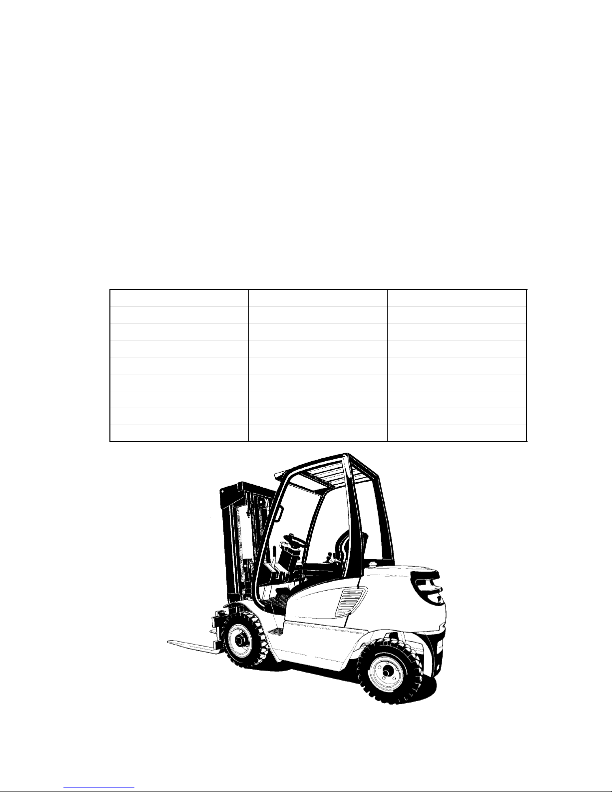
The load--bearing capacity depends on type. The type description indicates the
maximum permitted load. A DFG/T FG 316 can lift, transport and stack loads up to 1600
kg, and a DFG/TFG 320 loads up to 2000 kg.
Model
Load Capacity (kg) Wheel Base (mm)
DFG/TFG 316 1600 1400
DFG/TFG 320 2000 1400
DFG/TFG 420 2000 1685
DFG/TFG 425 2500 1685
DFG/TFG 430 3000 1685
DFG/TFG 540 4000 1985
DFG/TFG 545 4500 1985
DFG/TFG 550 5000 1985
B1
1206.GB
B Description of Truck
1 Description of Use
Forklift trucks to series DFG/TFG are driver’s cab forklifts with 4 wheel construction and
combustion engine. Trucks to series DFG have diesel engines, trucks of series TFG a
liquid petroleum gas engine.
The DFG/TFG 316--550 has a hydrodynamic drive. A combined creep/brake pedal
allows rapid lifting during creep running.
As of Februry 2007 the DFG/TFG 540--550 is equippd with an additional pedal. The left
pedal is a combination of crawl speed and brake pedal, and activates the rapid lift
function during slow travel. The middle pedal is a standard brake as well as emergency
brake pedal.
The load--bearing capacity depends on type. The type description indicates the
maximum permitted load. A DFG/T FG 316 can lift, transport and stack loads up to 1600
kg, and a DFG/TFG 320 loads up to 2000 kg.
Model
Load Capacity (kg) Wheel Base (mm)
DFG/TFG 316 1600 1400
DFG/TFG 320 2000 1400
DFG/TFG 420 2000 1685
DFG/TFG 425 2500 1685
DFG/TFG 430 3000 1685
DFG/TFG 540 4000 1985
DFG/TFG 545 4500 1985
DFG/TFG 550 5000 1985
Page 9
B2
1206.GB
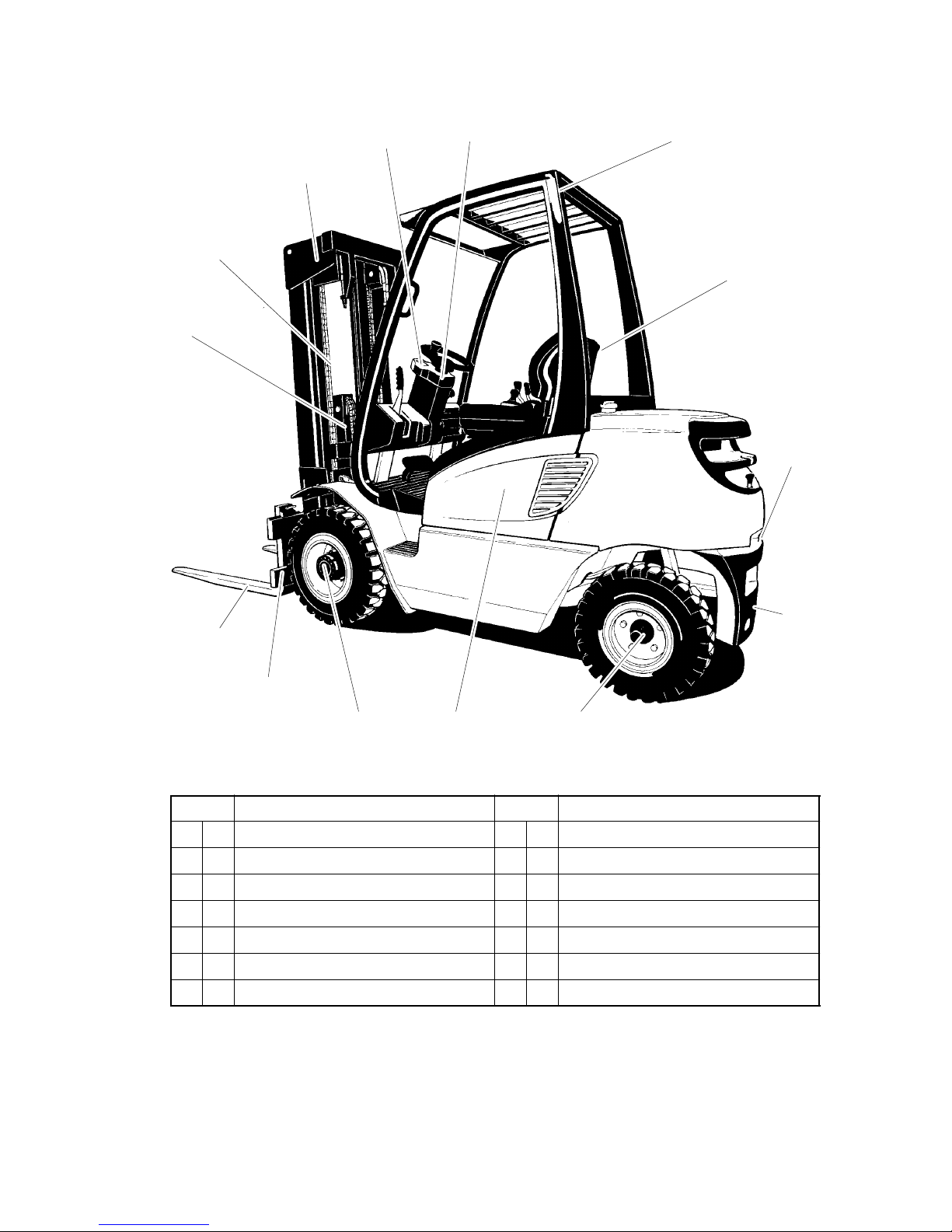
2 Description of Assemblies and Function
1
2
3
4
5
6
7
8
9
101112
13
14
Item Description Item Description
1 F Lift cylinder 8 F Towing coupling
2 F Lift chain 9 F Counterweight
3 F Mast assembly 10 F Steer axle
4 F Instrument panel 11 F Engine cover
5 F Steering column 12 F Drive axle
6 F Driver’s loadguard 13 F Carriage
7 F Driver’s seat 14 F Fork
B2
1206.GB
2 Description of Assemblies and Function
1
2
3
4
5
6
7
8
9
101112
13
14
Item Description Item Description
1 F Lift cylinder 8 F Towing coupling
2 F Lift chain 9 F Counterweight
3 F Mast assembly 10 F Steer axle
4 F Instrument panel 11 F Engine cover
5 F Steering column 12 F Drive axle
6 F Driver’s loadguard 13 F Carriage
7 F Driver’s seat 14 F Fork
Page 10

B3
1206.GB
2.1 Truck
Frame and Superstructure: A stable, torsionally rigid frame in which the equipment
and controls are installed protected, gives the truck a high static safety.The driver’s cab
is spring--mounted to dampen vibrations and noise.
A wide--opening top and two side panels on the engine cover (11) allow easy
maintenance and service. The hydraulic oil tank is side integrated into the frame on the
right and the fuel tank for the DFG series on the opposite side. The gas bottles for the
TFG series are attached to the counterweight (9) in a holder. The vertical free-- standing
exhaust pipe which opens high above the machine prevents the transmission of
vibration and sound waves and the penetration of exhaust gases into the driver’s cab.
Driver’s Cab: Non--slip steps and a handle on the roof pillar ensure easy entrance and
exit. The driver is protected by the roof (6). On the driver’s seat (7), the seat cushioning
and position are adjustable, and on the steering column (5) the angle of the steering
wheel can be modified. Simple operation by ergonomically arranged controls and a
virtually vibration--free driver’s cab means that minimum load is exerted on the driver.
The control and warning displays on the instrument panel (4) allow monitoring of the
systems during operation. As a r esult, the safety standard is very high.
The driver’s overhead guard must be checked prior to starting the truck for cracks, and
if damaged, must be repaired or replaced.
Engine: A silent water-- cooled engine with high power and low fuel consumption. T he
DFG series are fitted with diesel engines with very clean combustion under all
operating conditions and with low soot output. In the TFG series, liquid petroleum gas
engines are fitted with a very low residual exhaust value.
Drive: A load gearbox with gear oil cooler and torque converter is flanged directly onto
the engine. This transfers the power to the drive axle (12).
The direction lever on the operating console selects forwards/reverse or neutral.
Steering: Hydrostatic steering with a steering cylinder integrated into the steering axle
(10). The steering axle is fully floating in the frame to ensure good ground holding even
on uneven surfaces.
Brakes: The creep/brake pedal operates two hydraulic drum brakes acting on the drive
wheels. The drum brakes adjust automatically for wear. The parking brake acts
mechanically via Bowden cables on the drum brakes when the parking brake lever is
operated.
Wheels: All wheels are within the truck contour. The tyres are either pneumatic or
super--elastic tyres.
Hydraulic System: The hydraulic system gear pump is driven by the engine via the
secondary take--off from the load gears. The pump speed and hence the transport
volume is controlled by the engine speed via the accelerator pedal.
The hydraulic functions are controlled by the control lever via a m ultiple control valve.
Electrical System: 12 Volt system with starter battery and 3--phase alternator with
integral regulator. The starting repeat block prevents incorrect operation during
starting and a safety circuit allows the engine to start only when the direction lever is in
neutral. For diesel engines, a fast preglow system is fitted, whereas LPG engines have
a contactless electronic ignition system for fast easy starting of the engine. The engine
is turned off using the ignition/starter switch.
f
Page 11

B4
1206.GB
2.2 Mast
Mast: The trucks are fitted with tilting telescopic clear--view masts. Lifting cylinders (1)
arranged behind the profile of the mast (3) raise the inner mast. The load chains (2) with
pulley deflection raise the carriage (13) at the same time. The fork (14) is adjustably
mounted on the carriage. Adjustableside rollers and sliders absorb the lateral pressure
on the carriage from an unbalanced load.
In the double telescopic mast (ZT), lift is achieved by extending the inner mast only. For
double twin--lift masts (ZZ) and triple twin--lift masts (DZ), first the carriage with load
chains is raised via a short centrally--mounted cylinder and thus the first lift is possible
without altering the truck height (special clearance lift). Only then is the inner mast
extended.
Attachments: Mechanical and hydraulic attachments can be fitted (optional
equipment).
2.3 Changes in operational requirements
Should the operation of your frontlift change so that additional features such as lights,
cab or auxiliar y hydraulics, sideshift etc. are required, only officially approved
attachments or ancillary equipment may be used. Consult your nearest Depot or
Distributor for advice regarding any changes in operating or load handling procedures,
which would necessitate alterations to the truck or ancillary equipment.
Under no circumstances should any unauthorised addition or modification be made to
the truck, mast or attachment as originally supplied.
IMPORTANT
If the frontlift is modified or used with attachments other than those originally supplied,
new rating plates must be affixed in the cab and in the European Economic Area ( EEA)
countries the truck must be re-certified for conformity to the Machinery Directive
98/37/EEC as amended.
2.4 Safety devices
In addition to the driver’s overhead guard , the battery isolationswitch and key operated
ignition switch are classed as safety devices.
Battery isolation switch: The battery is connected and the truck is ready to run when
the battery isolation switch is raised. The battery is isolated when the battery isolation
switch is in the depressed position.
Key operated ignition switch: The removal of an ignition key by an authorized driver
upon leaving the truck, will prevent the truck from being operated by any unauthorized
person. The driver may not give the ignition key to another person without
authorization.
Page 12
B5
1206.GB
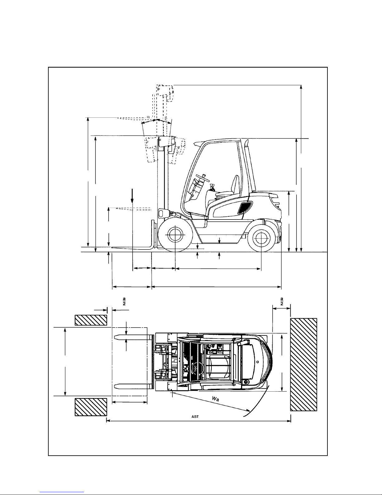
3 Technical Data -- Standard Equipment
Data to VDI 2198, subject to technical alterations and supplements
h
4
h
6
h
7
h
3
h
1
h
2
S
lL
2
y
xC
Q
m
1
m
2
B
d
e
b
A
B5
1206.GB
3 Technical Data -- Standard Equipment
Data to VDI 2198, subject to technical alterations and supplements
h
4
h
6
h
7
h
3
h
1
h
2
S
lL
2
y
xC
Q
m
1
m
2
B
d
e
b
A
Page 13

B6
1206.GB
Specification sh eet for lift trucks DFG 316--320
No. Description
Code
(Unit)
AX-J
1. Manufacturer Jungheinrich Jungheinrich
1.2 Model Name DFG 316 DFG 320
n
1.3 Drive: Electric, Diesel, Gasolene, LPG, other Diesel Diesel
icatio
n
1.4
Steering: Hand, Pedestrian, Standing, Seated, Order
Picking
Seated Seated
ecifi
1.5 Load Capacity Q(t) 1,6 2,0
Sp
e
1.6 Load Centre c(mm) 500 500
S
1.8 Load Distance x(mm) 395 395
1.9 Wheel Base y(mm) 1400 1400
2.1 Weight--unladen (kg) 3020 3270
ht
2.2 Axle Loading laden, front/rear (kg) 4000/620 4600/670
ei
g
2.3 Axle Loading unladen, front/rear (kg) 1320/1700 1240/2030
W
Longitudinal stability 1,66 1,59
is
3.1
Tyre type: Cushion, Super Elastic, Pneumatic,
Polyurethan
SE(L)/SE(L) SE(L)/SE(L)
ssi
s
3.2 Tyre Size: front 6.50--10 (14PR) 6.50-- 10 (14PR)
Ch
a
3.3 Tyre Size: rear 18x7--8 (16PR) 18x7--8 (16PR)
els/
C
3.5 Wheels, Numbers front/rear (x=traction) 2x/2 2x/2
he
e
3.6 Track width, front b10(mm) 895 895
W
3.7 Track width, rear b11(mm) 870 (offset) 870 (offset)
4.1 Tilt of Mast/Carriage, forward/backward Grad. 7/10 7/10
4.2 Mast Height, lowered h1(mm) 2080 2080
4.3 Free Lift h2(mm) 100 100
4.4 Lift Height h3(mm) 3090 3090
4.5 Height of extended mast h4(mm) 3670 3670
4.7 Height of overhead guard (Cabin) h6(mm) 2130 2130
4.8 Seat Height / Head clearance (SIP 100mm) h7(mm) 1005/1065 1005/1065
4.12 Coupling height h10(mm) 375/545 375/545
ons
4.19 Overall Length l1(mm) 3245 3300
nsi
o
4.20 Length to Fork Face l2(mm) 2245 2300
ime
n
4.21 Overall Width b1/b2(mm) 1070 1070
Di
4.22 Fork Dimension s/e/l(mm) 40/100/1000 40/100/1000
4.23 Carriage DIN 15173, ISO 2328, Class/Form A,B ISO 2A ISO 2A
4.24 Fork Carriage width / outside forks b3(mm) 1000/849 1000/849
4.31 Ground Clearance laden under mast m1(mm) 115 115
4.32 Ground Clearance at the centre of Wheel Base m2(mm) 135 135
4.33 Aisle width with pallet 1000x1200 transverse Ast(mm) 3570 3615
4.34 Aisle width with pallet 800x1200 Pallet longitudinal Ast(mm) 3770 3815
4.35 Turning Radius Wa(mm) 1975 2020
5.1 Travel Speed laden/unladen (km/h) 18,7/19,0 18,4/18,7
5.2 Lifting Speed laden/unladen (m/s) 0,61/0,65 0,60/0,65
nc
e
5.3 Lowering Speed laden/unladen (m/s) 0,56/0,48 0,57/0,48
rma
5.5 Draw-bar-pull laden/unladen (kN) 12,7/9,0 12,6/8,2
rfo
r
5.7 Gradeability laden/unladen (%) 26/23 23/21
Pe
5.9 Acceleration time, laden/unladen s 5,0/4,5 5,1/4,4
5.10 Service brake type mech./hydr. mech./hydr.
7.1 Engine Manufacturer/Model 404C.22 404C.22
e
7.2 Engine Output to ISO 1585 (kw) 34,1 34,1
gin
e
7.3 Rated Rotation (1/min) 2400 2400
En
g
7.4 Nº of Cy linders/Displacement (/cm#) 4/2216 4/2216
max. torque Nm/rpm 143/1800 135/1900
8.1 Type of Drive Control hydrodyn. hydrodyn.
ers
8.2 Hydraulic Oil Pressure for Attachments (bar) 160 160
th
e
8.3 Oil flow for attachments l/min 45 45
O
8.4 Noise Level at Operator’s Ear dB(A) <80 <80
Page 14

B7
1206.GB
Specification sh eet for lift trucks TFG 316/320
No. Description
Code
(Unit)
AX-J
1. Manufacturer Jungheinrich Jungheinrich
1.2 Model Name TFG 316 TFG 320
n
1.3 Drive: Electric, Diesel, Gasolene, LPG, other LPG LPG
icatio
n
1.4
Steering: Hand, Pedestrian, Standing, Seated, Order
Picking
Seated Seated
ecifi
1.5 Load Capacity Q(t) 1,6 2,0
Sp
e
1.6 Load Centre c(mm) 500 500
S
1.8 Load Distance x(mm) 395 395
1.9 Wheel Base y(mm) 1400 1400
2.1 Weight--unladen (kg) 3000 3250
ht
2.2 Axle Loading laden, front/rear (kg) 4030/570 4630/620
ei
g
2.3 Axle Loading unladen, front/rear (kg) 1270/1730 1190/2060
W
Longitudinal stability 1,69 1,61
is
3.1
Tyre type: Cushion, Super Elastic, Pneumatic,
Polyurethan
SE(L)/SE(L) SE(L)/SE(L)
ssi
s
3.2 Tyre Size: front 6.50--10 (14PR) 6.50-- 10 (14PR)
Ch
a
3.3 Tyre Size: rear 18x7--8 (16PR) 18x7--8 (16PR)
els/
C
3.5 Wheels, Numbers front/rear (x=traction) 2x/2 2x/2
he
e
3.6 Track width, front b10(mm) 895 895
W
3.7 Track width, rear b11(mm) 870 (offset) 870 (offset)
4.1 Tilt of Mast/Carriage, forward/backward Grad. 7/10 7/10
4.2 Mast Height, lowered h1(mm) 2080 2080
4.3 Free Lift h2(mm) 100 100
4.4 Lift Height h3(mm) 3090 3090
4.5 Height of extended mast h4(mm) 3670 3670
4.7 Height of overhead guard (Cabin) h6(mm) 2130 2130
4.8 Seat Height / Head clearance (SIP 100mm) h7(mm) 1005/1065 1005/1065
4.12 Coupling height h10(mm) 375/545 375/545
ons
4.19 Overall Length l1(mm) 3245 3300
nsi
o
4.20 Length to Fork Face l2(mm) 2245 2300
ime
n
4.21 Overall Width b1/b2(mm) 1070 1070
Di
4.22 Fork Dimension s/e/l(mm) 40/100/1000 40/100/1000
4.23 Carriage DIN 15173, ISO 2328, Class/Form A,B ISO 2A ISO 2A
4.24 Fork Carriage width / outside forks b3(mm) 1000/849 1000/849
4.31 Ground Clearance laden under mast m1(mm) 115 115
4.32 Ground Clearance at the centre of Wheel Base m2(mm) 135 135
4.33 Aisle width with pallet 1000x1200 transverse Ast(mm) 3570 3615
4.34 Aisle width with pallet 800x1200 Pallet longitudinal Ast(mm) 3770 3815
4.35 Turning Radius Wa(mm) 1975 2020
5.1 Travel Speed laden/unladen (km/h) 18,5/19,5 18/19
5.2 Lifting Speed laden/unladen (m/s) 0,56/0,65 0,55/0,65
nc
e
5.3 Lowering Speed laden/unladen (m/s) 0,56/0,48 0,57/0,48
rma
5.5 Draw-bar-pull laden/unladen (kN) 10,1/8,6 9,8/7,8
rfo
r
5.7 Gradeability laden/unladen (%) 24/22 22/20
Pe
5.9 Acceleration time, laden/unladen s 5,2/4,6 5,4/4,7
5.10 Service brake type mech./hydr. mech./hydr.
7.1 Engine Manufacturer/Model FE FE
e
7.2 Engine Output to ISO 1585 (kw) 26,0 26,0
gin
e
7.3 Rated Rotation (1/min) 2400 2400
En
g
7.4 Nº of Cy linders/Displacement (/cm#) 4/1988 4/1988
max. torque Nm/rpm 120/1600 120/1600
8.1 Type of Drive Control hydrodyn. hydrodyn.
ers
8.2 Hydraulic Oil Pressure for Attachments (bar) 160 160
th
e
8.3 Oil flow for attachments l/min 45 45
O
8.4 Noise Level at Operator’s Ear dB(A) <80 <80
Page 15

B8
1206.GB
Specification sh eet for lift trucks DFG 420--430
No. Description
Code
(Unit)
BX-J
1. Manufacturer Jungheinrich Jungheinrich Jungheinrich
1.2 Model Name DFG 420 DFG 425 DFG 430
n
1.3 Drive: Electric, Diesel, Gasolene, LPG, other Diesel Diesel Diesel
icatio
n
1.4
Steering: Hand, Pedestrian, Standing, Seated, Order
Picking
Seated Seated Seated
ecifi
1.5 Load Capacity Q(t) 2,0 2,5 3,0
Sp
e
1.6 Load Centre c(mm) 500 500 500
S
1.8 Load Distance x(mm) 450 450 480
1.9 Wheel Base y(mm) 1685 1685 1685
2.1 Weight--unladen (kg) 3760 4190 4540
ht
2.2 Axle Loading laden, front/rear (kg) 5220/540 5820/870 6680/860
ei
g
2.3 Axle Loading unladen, front/rear (kg) 2000/1760 1840/2350 1850/2690
W
Longitudinal stability 1,54 1,65 1,48
is
3.1
Tyre type: Cushion, Super Elastic, Pneumatic,
Polyurethan
SE(L)/SE(L) SE(L) /SE(L) SE(L)/SE(L)
ssi
s
3.2 Tyre Size: front 7.00--12 (12PR) 7.00--12 (12PR) 27x 10--12 (14PR)
Ch
a
3.3 Tyre Size: rear 6.50--10 (10PR) 6.50--10 (10PR) 6.50--10 (10PR)
els/
C
3.5 Wheels, Numbers front/rear (x=traction) 2x/2 2x/2 2x/2
he
e
3.6 Track width, front b10(mm) 990 990 1045
W
3.7 Track width, rear b11(mm) 938 (offset) 938 (offset) 938
4.1 Tilt of Mast/Carriage, forward/backward Grad. 6/6 6/6 6/6
4.2 Mast Height, lowered h1(mm) 2300 2300 2300
4.3 Free Lift h2(mm) 150 150 150
4.4 Lift Height h3(mm) 3300 3300 3300
4.5 Height of extended mast h4(mm) 3896 3896 3896
4.7 Height of overhead guard (Cabin) h6(mm) 2220 2220 2220
4.8 Seat Height / Head clearance (SIP 100mm) h7(mm) 1095/1065 1095/1065 1095/1065
ns
4.12 Coupling height h10(mm) 440/615 440/615 440/615
sio
n
4.19 Overall Length l1(mm) 3515 3525 3640
en
s
4.20 Length to Fork Face l2(mm) 2515 2525 2640
Di
m
4.21 Overall Width b1/b2(mm) 1170 1170 1285
D
4.22 Fork Dimension s/e/l(mm) 40/100/1000 40/100/1000 50/125/1000
4.23 Carriage DIN 15173, ISO 2328, Class/Form A,B ISO 2A ISO 2A ISO 3A
4.31 Ground Clearance laden under mast m1(mm) 125 125 125
4.32 Ground Clearance at the centre of Wheel Base m2(mm) 132 132 142
4.33 Aisle width with pallet 1000x1200 transverse Ast(mm) 3925 3935 4050
4.34 Aisle width with pallet 800x1200 Pallet longitudinal Ast(mm) 4125 4135 4250
4.35 Turning Radius Wa(mm) 2265 2275 2360
5.1 Travel Speed laden/unladen (km/h) 18,7/18,9 18,5/18,7 18,6/18,8
5.2 Lifting Speed laden/unladen (m/s) 0,56/0,60 0,56/0,60 0,55/0,60
nc
e
5.3 Lowering Speed laden/unladen (m/s) 0,53/0,55 0,53/0,55 0,55/0,52
rma
5.5 Draw-bar-pull laden/unladen (kN) 16,9/11,8 16,7/10,8 16,6/12,2
rfo
r
5.7 Gradeability laden/unladen (%) 31/31 26/25 22/27
Pe
5.9 Acceleration time, laden/unladen s 5,0/4,6 5,12/4,50 5,5/4,7
5.10 Service brake type mech./hydr. mech./hydr. mech./hydr.
7.1 Engine Manufacturer/Model
704.30/704.26
(12.03 an later)
704.30/704.26
(12.03 an later)
704.30/704.26
(12.03 an later)
ne
7.2 Engine Output to ISO 1585 (kw) 40 40 40
ngi
n
7.3 Rated Rotation (1/min) 2100 2100 2100
E
n
7.4 Nº of Cy linders/Displacement (/cm#) 4/2955 4/2955 4/2955
max. torque Nm/rpm 190/1600 190/1600 190/1600
8.1 Type of Drive Control hydrodyn. hydrodyn. hydrodyn.
ers
8.2 Hydraulic Oil Pressure for Attachments (bar) 160 160 160
th
e
8.3 Oil flow for attachments l/min 60 60 60
O
8.4 Noise Level at Operator’s Ear dB(A) <80 <80 <80
Page 16

B9
1206.GB
Specification sh eet for lift trucks TFG 420--430
No. Description
Code
(Unit)
BX-J
1. Manufacturer Jungheinrich Jungheinrich Jungheinrich
1.2 Model Name TFG 420 TFG 425 TFG 430
n
1.3 Drive: Electric, Diesel, Gasolene, LPG, other LPG LPG LPG
icatio
n
1.4
Steering: Hand, Pedestrian, Standing, Seated, Order
Picking
Seated Seated Seated
ecifi
1.5 Load Capacity Q(t) 2,0 2,5 3,0
Sp
e
1.6 Load Centre c(mm) 500 500 500
S
1.8 Load Distance x(mm) 450 450 480
1.9 Wheel Base y(mm) 1685 1685 1685
2.1 Weight--unladen (kg) 3730 4160 4510
ht
2.2 Axle Loading laden, front/rear (kg) 5200/530 5800/860 6660/850
ei
g
2.3 Axle Loading unladen, front/rear (kg) 1980/1750 1820/2340 1830/2680
W
Longitudinal stability 1,54 1,65 1,48
is
3.1
Tyre type: Cushion, Super Elastic, Pneumatic,
Polyurethan
SE(L)/SE(L) SE(L) /SE(L) SE(L)/SE(L)
ssi
s
3.2 Tyre Size: front 7.00--12 (12PR) 7.00--12 (12PR) 27x 10--12 (14PR)
Ch
a
3.3 Tyre Size: rear 6.50--10 (10PR) 6.50--10 (10PR) 6.50--10 (10PR)
els/
C
3.5 Wheels, Numbers front/rear (x=traction) 2x/2 2x/2 2x/2
he
e
3.6 Track width, front b10(mm) 990 990 1045
W
3.7 Track width, rear b11(mm) 938 (offset) 938 (offset) 938
4.1 Tilt of Mast/Carriage, forward/backward Grad. 6/6 6/6 6/6
4.2 Mast Height, lowered h1(mm) 2300 2300 2300
4.3 Free Lift h2(mm) 150 150 150
4.4 Lift Height h3(mm) 3300 3300 3300
4.5 Height of extended mast h4(mm) 3896 3896 3896
4.7 Height of overhead guard (Cabin) h6(mm) 2220 2220 2220
4.8 Seat Height / Head clearance (SIP 100mm) h7(mm) 1095/1065 1095/1065 1095/1065
ns
4.12 Coupling height h10(mm) 440/615 440/615 440/615
sio
n
4.19 Overall Length l1(mm) 3515 3525 3640
en
s
4.20 Length to Fork Face l2(mm) 2515 2525 2640
Di
m
4.21 Overall Width b1/b2(mm) 1170 1170 1285
D
4.22 Fork Dimension s/e/l(mm) 40/100/1000 40/100/1000 50/125/1000
4.23 Carriage DIN 15173, ISO 2328, Class/Form A,B ISO 2A ISO 2A ISO 3A
4.31 Ground Clearance laden under mast m1(mm) 125 125 125
4.32 Ground Clearance at the centre of Wheel Base m2(mm) 132 132 142
4.33 Aisle width with pallet 1000x1200 transverse Ast(mm) 3925 3935 4050
4.34 Aisle width with pallet 800x1200 Pallet longitudinal Ast(mm) 4125 4135 4250
4.35 Turning Radius Wa(mm) 2265 2275 2360
5.1 Travel Speed laden/unladen (km/h) 18,7/18,9 18,5/18,7 18,6/18,8
5.2 Lifting Speed laden/unladen (m/s) 0,56/0,60 0,56/0,60 0,55/0,60
nc
e
5.3 Lowering Speed laden/unladen (m/s) 0,53/0,55 0,53/0,55 0,55/0,52
rma
5.5 Draw-bar-pull laden/unladen (kN) 16,4/11,7 16,2/10,8 16,1/12,1
rfo
r
5.7 Gradeability laden/unladen (%) 30/31 26/25 22/27
Pe
5.9 Acceleration time, laden/unladen s 5,15/4,80 5,31/4,50 6,3/5,3
5.10 Service brake type mech.hydr. mech.hydr. mech.hydr.
7.1 Engine Manufacturer/Model 3.0 L4 3.0 L4 3.0 L4
e
7.2 Engine Output to ISO 1585 (kw) 44 44 44
gin
e
7.3 Rated Rotation (1/min) 2200 2200 2200
En
g
7.4 Nº of Cy linders/Displacement (/cm#) 4/2966 4/2966 4/2966
max. torque Nm/rpm 196/1600 196/1600 196/1600
8.1 Type of Drive Control hydrodyn. hydrodyn. hydrodyn.
ers
8.2 Hydraulic Oil Pressure for Attachments (bar) 160 160 160
th
e
8.3 Oil flow for attachments l/min 60 60 60
O
8.4 Noise Level at Operator’s Ear dB(A) <80 <80 <80
Page 17

B10
1206.GB
Specification sh eet for lift trucks DFG 540--550
No. Description
Code
(Unit)
CX-J
1. Manufacturer Jungheinrich Jungheinrich Jungheinrich
1.2 Model Name DFG 540 DFG 545 DFG 550
on
1.3 Drive: Electric, Diesel, Gasolene, LPG, other Diesel Diesel Diesel
ati
o
1.4 Steering: Hand, Pedestrian, Standing, Seated Seated Seated Seated
cifi
c
1.5 Load Capacity Q(t) 4,0 4,5 5,0
pe
c
1.6 Load Centre c(mm) 500 500 600
S
1.8 Load Distance x(mm) 564 564 579
1.9 Wheel Base y(mm) 1985 1985 1985
2.1 Weight--unladen (kg) 6140 6540 7080
ht
2.2 Axle Loading laden, front/rear (kg) 9100/1040 9980/1060 10700/1380
ei
g
2.3 Axle Loading unladen, front/rear (kg) 2860/3280 2980/3560 2840/4240
W
Longitudinal stability
3.1 Tyre type: Cushion, Super Elastic, Pneu., Polyurethan SE(L)/SE(L) SE(L)/SE( L) SE(L)/SE(L)
ssis
3.2 Tyre Size: front 8.25--15 (18PR) 8.25--15 (18PR) 3.00--15 (18PR)
ha
s
3.3 Tyre Size: rear 7.00--12 (12PR) 7.00--12 (12PR) 7.00--12 (12PR)
ls/
C
3.5 Wheels, Numbers front/rear (x=traction) 2x/2 2x/2 2x/2
hee
l
3.6 Track width, front b10(mm) 1165 1165 1165
W
h
3.7 Track width, rear b11(mm) 1163 1163 1163
4.1 Tilt of Mast/Carriage, forward/backward Grad. 7/11 7/11 7/11
4.2 Mast Height, lowered h1(mm) 2540 2540 2540
4.3 Free Lift h2(mm) 150 150 150
4.4 Lift Height h3(mm) 3500 3500 3500
4.5 Height of extended mast h4(mm) 4200 4200 4350
4.7 Height of overhead guard (Cabin) h6(mm) 2350 2350 2350
4.8 Seat Height / Head clearance (SIP 100mm) h7(mm) 1225 1225 1225
4.12 Coupling height h10(mm) 535/700 535/700 535/700
s
4.19 Overall Length l1(mm) 4140 4140 4240
sio
n
4.20 Length to Fork Face l2(mm) 2990 2990 2990
en
s
4.21 Overall Width b1/b2(mm) 1400 1400 1400
Di
m
4.22 Fork Dimension s/e/l(mm) 50/125/1150 50/125/1150 60/150/1150
D
4.23 Carriage DIN 15173, ISO 2328, Class/Form A,B ISO 3A ISO 3A ISO 4A
4.24 Fork Carriage Width b
3
1260 1260 1260
4.31 Ground Clearance laden under mast m1(mm) 190 190 190
4.32 Ground Clearance at the centre of Wheel Base m2(mm) 230 230 230
4.33 Aisle width with pallet 1000x1200 transverse Ast(mm) 4440 4440 4555
4.34 Aisle width with pallet 800x1200 Pallet longitudinal Ast(mm) 4640 4640 4755
4.35 Turning Radius Wa(mm) 2650 2650 2750
4.36 Smalles t Distance to Pivot Point b
13
900 900 900
5.1 Travel Speed laden/unladen (km/h) 24,5/25,4 23,5/24,8 22,3/24,3
e
5.2 Lifting Speed laden/unladen (m/s) 0,52/0,55 0,51/0,55 0,50/0,55
nc
e
5.3 Lowering Speed laden/unladen (m/s) 0,52/0,38 0,52/0,38 0,52/0,38
rma
5.5 Draw-bar-pull laden/unladen (kN) 34,00/16,50 34,00/16,5 34,00/16,5
rfo
r
5.7 Gradeability laden/unladen (%) 33,5/26,8 30,7/25,2 28/23,3
Pe
5.9 Acceleration time, laden/unladen s 4,8/4,7 4,9/4,8 6,0/5,6
5.10 Service brake type mech./hydr. mech./hydr. mech./hydr.
7.1 Engine Manufacturer/Model 1004.4 2 1004.4 2 1004.4 2
e
7.2 Engine Output to ISO 1585 (kw) 60 60 60
gin
e
7.3 Rated Rotation (1/min) 2200 2200 2200
En
g
7.4 Nº of Cy linders/Displacement (/cm#) 4/4230 4/4230 4/4230
max. torque Nm/rpm
8.1 Type of Drive Control hydrodyn. hydrodyn. hydrodyn.
s
8.2 Hydraulic Oil Pressure for Attachments (bar) 160 160 160
her
s
8.3 Oil flow for attachments l/min 30 30 30
Ot
h
8.4 Noise Level at Operator’s Ear dB(A) 78 78 78
8.5 Trailer Coupling Type / DIN Type 15170 / type h 15170 / type h 15170 / type h
Page 18

B11
1206.GB
Specification sh eet for lift trucks DFG 540--550 (09/03 and later)
No. Description
Code
(Unit)
CX-J
1. Manufacturer Jungheinrich Jungheinrich Jungheinrich
1.2 Model Name DFG 540 DFG 545 DFG 550
on
1.3 Drive: Electric, Diesel, Gasolene, LPG, other Diesel Diesel Diesel
ati
o
1.4 Steering: Hand, Pedestrian, Standing, Seated Seated Seated Seated
cifi
c
1.5 Load Capacity Q(t) 4,0 4,5 5,0
pe
c
1.6 Load Centre c(mm) 500 500 600
S
1.8 Load Distance x(mm) 564 564 579
1.9 Wheel Base y(mm) 1985 1985 1985
2.1 Weight--unladen (kg) 6279 6669 7434
ht
2.2 Axle Loading laden, front/rear (kg) 8954/1325 9869/1300 10762/1673
ei
g
2.3 Axle Loading unladen, front/rear (kg) 2810/3469 2937/3732 2795/4639
W
Longitudinal stability
3.1 Tyre type: Cushion, Super Elastic, Pneu., Polyurethan SE(L)/SE(L) SE(L)/SE( L) SE(L)/SE(L)
ssis
3.2 Tyre Size: front 3.00--15 (18PR) 3.00--15 (18PR) 3.00--15 (18PR)
ha
s
3.3 Tyre Size: rear 28 x 9 -- 15 28 x 9 -- 15 28 x 9 -- 15
ls/
C
3.5 Wheels, Numbers front/rear (x=traction) 2x/2 2x/2 2x/2
hee
l
3.6 Track width, front b10(mm) 1180 1180 1170
W
h
3.7 Track width, rear b11(mm) 1160 1160 1160
4.1 Tilt of Mast/Carriage, forward/backward Grad. 7/11 7/11 7/11
4.2 Mast Height, lowered h1(mm) 2540 2540 2540
4.3 Free Lift h2(mm) 150 150 150
4.4 Lift Height h3(mm) 3500 3500 3500
4.5 Height of extended mast h4(mm) 4200 4200 4350
4.7 Height of overhead guard (Cabin) h6(mm) 2370 2370 2370
4.8 Seat Height / Head clearance (SIP 100mm) h7(mm) 1255/1010 1255/1010 1255/1010
4.12 Coupling height h10(mm) 535/700 535/700 535/700
s
4.19 Overall Length l1(mm) 4145 4145 4260
sio
n
4.20 Length to Fork Face l2(mm) 2995 2995 3110
en
s
4.21 Overall Width b1/b2(mm) 1450 1450 1450
Di
m
4.22 Fork Dimension s/e/l(mm) 50/125/1150 50/125/1150 60/150/1150
D
4.23 Carriage DIN 15173, ISO 2328, Class/Form A,B ISO 3A ISO 3A ISO 4A
4.24 Fork Carriage Width b
3
1260 1260 1260
4.31 Ground Clearance laden under mast m1(mm) 190 190 190
4.32 Ground Clearance at the centre of Wheel Base m2(mm) 230 230 230
4.33 Aisle width with pallet 1000x1200 transverse Ast(mm) 4419 4419 4569
4.34 Aisle width with pallet 800x1200 Pallet longitudinal Ast(mm) 4619 4619 4769
4.35 Turning Radius Wa(mm) 2655 2655 2790
4.36 Smalles t Distance to Pivot Point b
13
900 900 900
5.1 Travel Speed laden/unladen (km/h) 25,3/25,5 24,5/25,5 24,8/25,5
e
5.2 Lifting Speed laden/unladen (m/s) 0,52/0,53 0,51/0,53 0,50/0,53
nc
e
5.3 Lowering Speed laden/unladen (m/s) 0,51/0,49 0,51/0,49 0,51/0,49
rma
5.5 Draw-bar-pull laden/unladen (kN) 41,20/23,50 40,97/24,47 33,50/21,10
rfo
r
5.7 Gradeability laden/unladen (%) 36/34 34/33 25,5/25,7
Pe
5.9 Acceleration time, laden/unladen s 5/4,5 5/4,5 5,1/4,5
5.10 Service brake type mech./hydr. mech./hydr. mech./hydr.
7.1 Engine Manufacturer/Model 1104C--44 1104C--44 1104C--44
e
7.2 Engine Output to ISO 1585 (kw) 61,5 61,5 61,5
gin
e
7.3 Rated Rotation (1/min) 2200 2200 2200
En
g
7.4 Nº of Cy linders/Displacement (/cm#) 4/4400 4/4400 4/4400
max. torque Nm/rpm 302/1400 302/1400 302/1400
8.1 Type of Drive Control hydrodyn. hydrodyn. hydrodyn.
s
8.2 Hydraulic Oil Pressure for Attachments (bar) 160 160 160
her
s
8.3 Oil flow for attachments l/min 30 30 30
Ot
h
8.4 Noise Level at Operator’s Ear dB(A) 78 78 78
8.5 Trailer Coupling Type / DIN Type 15170 / type h 15170 / type h 15170 / type h
B11
1206.GB
Specification sh eet for lift trucks DFG 540--550 (09/03 and later)
No. Description
Code
(Unit)
CX-J
1. Manufacturer Jungheinrich Jungheinrich Jungheinrich
1.2 Model Name DFG 540 DFG 545 DFG 550
on
1.3 Drive: Electric, Diesel, Gasolene, LPG, other Diesel Diesel Diesel
ati
o
1.4 Steering: Hand, Pedestrian, Standing, Seated Seated Seated Seated
cifi
c
1.5 Load Capacity Q(t) 4,0 4,5 5,0
pe
c
1.6 Load Centre c(mm) 500 500 600
S
1.8 Load Distance x(mm) 564 564 579
1.9 Wheel Base y(mm) 1985 1985 1985
2.1 Weight-- unladen (kg) 6279 6669 7434
ht
2.2 Axle Loading laden, front/rear (kg) 8954/1325 9869/1300 10762/1673
ei
g
2.3 Axle Loading unladen, front/rear (kg) 2810/3469 2937/3732 2795/4639
W
Longitudinal stability
3.1 Tyre type: Cushion, Super Elastic, Pneu., Polyurethan SE(L)/SE(L) SE(L)/SE( L) SE(L)/SE(L)
ssis
3.2 Tyre Size: front 3.00--15 (18PR) 3.00-- 15 (18PR) 3.00-- 15 (18PR)
ha
s
3.3 Tyre Size: rear 28 x 9 -- 15 28 x 9 -- 15 28 x 9 -- 15
ls/
C
3.5 Wheels, Numbers front/rear (x=traction) 2x/2 2x/2 2x/2
hee
l
3.6 Track width, front b10(mm) 1180 1180 1170
W
h
3.7 Track width, rear b11(mm) 1160 1160 1160
4.1 Tilt of Mast/Carriage, forward/backward Grad. 7/11 7/11 7/11
4.2 Mast Height, lowered h1(mm) 2540 2540 2540
4.3 Free Lift h2(mm) 150 150 150
4.4 Lift Height h3(mm) 3500 3500 3500
4.5 Height of extended mast h4(mm) 4200 4200 4350
4.7 Height of overhead guard (Cabin) h6(mm) 2370 2370 2370
4.8 Seat Height / Head clearance (SIP 100mm) h7(mm) 1255/1010 1255/1010 1255/1010
4.12 Coupling height h10(mm) 535/700 535/700 535/700
s
4.19 Overall Length l1(mm) 4145 4145 4260
sio
n
4.20 Length to Fork Face l2(mm) 2995 2995 3110
en
s
4.21 Overall Width b1/b2(mm) 1450 1450 1450
Di
m
4.22 Fork Dimension s/e/l(mm) 50/125/1150 50/125/1150 60/150/1150
D
4.23 Carriage DIN 15173, ISO 2328, Class/Form A,B ISO 3A ISO 3A ISO 4A
4.24 Fork Carriage Width b
3
1260 1260 1260
4.31 Ground Clearance laden under mast m1(mm) 190 190 190
4.32 Ground Clearance at the centre of Wheel Base m2(mm) 230 230 230
4.33 Aisle width with pallet 1000x1200 transverse Ast(mm) 4419 4419 4569
4.34 Aisle width with pallet 800x1200 Pallet longitudinal Ast(mm) 4619 4619 4769
4.35 Turning Radius Wa(mm) 2655 2655 2790
4.36 Smalles t Distance to Pivot Point b
13
900 900 900
5.1 Travel Speed laden/unladen (km/h) 25,3/25,5 24,5/25,5 24,8/25,5
e
5.2 Lifting Speed laden/unladen (m/s) 0,52/0,53 0,51/0,53 0,50/0,53
nc
e
5.3 Lowering Speed laden/unladen (m/s) 0,51/0,49 0,51/0,49 0,51/0,49
rma
5.5 Draw-bar-pull laden/unladen (kN) 41,20/23,50 40,97/24,47 33,50/21,10
rfo
r
5.7 Gradeability laden/unladen (%) 36/34 34/33 25,5/25,7
Pe
5.9 Acceleration time, laden/unladen s 5/4,5 5/4,5 5,1/4,5
5.10 Service brake type mech./hydr. mech./hydr. mech./hydr.
7.1 Engine Manufacturer/Model 1104C--44 1104C-- 44 1104C--44
e
7.2 Engine Output to ISO 1585 (kw) 61,5 61,5 61,5
gin
e
7.3 Rated Rotation (1/min) 2200 2200 2200
En
g
7.4 Nº of Cy linders/Displacement (/cm#) 4/4400 4/4400 4/4400
max. torque Nm/rpm 302/1400 302/1400 302/1400
8.1 Type of Drive Control hydrodyn. hydrodyn. hydrodyn.
s
8.2 Hydraulic Oil Pressure for Attachments (bar) 160 160 160
her
s
8.3 Oil flow for attachments l/min 30 30 30
Ot
h
8.4 Noise Level at Operator’s Ear dB(A) 78 78 78
8.5 Trailer Coupling Type / DIN Type 15170 / type h 15170 / type h 15170 / type h
Page 19

B12
1206.GB
Specification sh eet for lift trucks TFG 540--550
No. Description
Code
(Unit)
CX-J
1. Manufacturer Jungheinrich Jungheinrich Jungheinrich
1.2 Model Name TFG 540 TFG 545 TFG 550
on
1.3 Drive: Electric, Diesel, Gasolene, LPG, other LPG LPG LPG
ati
o
1.4 Steering: Hand, Pedestrian, Standing, Seated Seated Seated Seated
cifi
c
1.5 Load Capacity Q(t) 4,0 4,5 5,0
pe
c
1.6 Load Centre c(mm) 500 500 600
S
1.8 Load Distance x(mm) 564 564 579
1.9 Wheel Base y(mm) 1985 1985 1985
2.1 Weight-- unladen (kg) 6140 6540 7080
ht
2.2 Axle Loading laden, front/rear (kg) 9100/1040 9980/1060 10720/1360
ei
g
2.3 Axle Loading unladen, front/rear (kg) 2860/3280 2980/3560 2840/4240
W
Longitudinal stability
3.1 Tyre type: Cushion, Super Elastic, Pneu., Polyurethan SE(L)/SE(L) SE(L)/SE( L) SE(L)/SE(L)
ssis
3.2 Tyre Size: front 8.25--15 (18PR) 8.25-- 15 (18PR) 3.00-- 15 (18PR)
ha
s
3.3 Tyre Size: rear 7.00-- 12 (12PR) 7.00--12 (12PR) 7.00- -12 (12PR)
ls/
C
3.5 Wheels, Numbers front/rear (x=traction) 2x/2 2x/2 2x/2
hee
l
3.6 Track width, front b10(mm) 1165 1165 1165
W
h
3.7 Track width, rear b11(mm) 1163 1163 1163
4.1 Tilt of Mast/Carriage, forward/backward Grad. 7/11 7/11 7/11
4.2 Mast Height, lowered h1(mm) 2540 2540 2540
4.3 Free Lift h2(mm) 150 150 150
4.4 Lift Height h3(mm) 3500 3500 3500
4.5 Height of extended mast h4(mm) 4200 4200 4350
4.7 Height of overhead guard (Cabin) h6(mm) 2350 2350 2350
4.8 Seat Height / Head clearance (SIP 100mm) h7(mm) 1225 1225 1225
4.12 Coupling height h10(mm) 535/700 535/700 535/700
s
4.19 Overall Length l1(mm) 4140 4140 4240
sio
n
4.20 Length to Fork Face l2(mm) 2900 2900 3090
en
s
4.21 Overall Width b1/b2(mm) 1400 1400 1400
Di
m
4.22 Fork Dimension s/e/l(mm) 50/125/1150 50/125/1150 60/150/1150
D
4.23 Carriage DIN 15173, ISO 2328, Class/Form A,B ISO 3A ISO 3A ISO 4A
4.24 Fork Carriage Width b
3
1260 1260 1260
4.31 Ground Clearance laden under mast m1(mm) 190 190 190
4.32 Ground Clearance at the centre of Wheel Base m2(mm) 230 230 230
4.33 Aisle width with pallet 1000x1200 transverse Ast(mm) 4440 4440 4555
4.34 Aisle width with pallet 800x1200 Pallet longitudinal Ast(mm) 4640 4640 4755
4.35 Turning Radius Wa(mm) 2650 2650 2750
4.36 Smalles t Distance to Pivot Point b
13
900 900 900
5.1 Travel Speed laden/unladen (km/h) 24,5/25,4 23,8/24,8 22,3/24,3
e
5.2 Lifting Speed laden/unladen (m/s) 0,52/0,55 0,51/0,55 0,50/0,55
nc
e
5.3 Lowering Speed laden/unladen (m/s) 0,52/0,38 0,52/0,38 0,52/0,38
rma
5.5 Draw-bar-pull laden/unladen (kN) 32,0/16,0 32,0/16,0 32,0/16,0
rfo
r
5.7 Gradeability laden/unladen (%) 33,5/26 30,7/24,5 28/22,6
Pe
5.9 Acceleration time, laden/unladen s 5,6/4,5 5,7/4,7 6,3/4,8
5.10 Service brake type mech./hydr. mech./hydr. mech./hydr.
7.1 Engine Manufacturer/Model 4.3 V6 4.3 V6 4.3 V6
e
7.2 Engine Output to ISO 1585 (kw) 67 67 67
gin
e
7.3 Rated Rotation (1/min) 2200 2200 2200
En
g
7.4 Nº of Cy linders/Displacement (/cm#) 6/4294 6/4294 6/4294
max. torque Nm/rpm
8.1 Type of Drive Control hydrodyn. hydrodyn. hydrodyn.
s
8.2 Hydraulic Oil Pressure for Attachments (bar) 160 160 160
her
s
8.3 Oil flow for attachments l/min 30 30 30
Ot
h
8.4 Noise Level at Operator’s Ear dB(A) 78 78 78
8.5 Trailer Coupling Type / DIN Type 15170 / type h 15170 / type h 15170 / type h
Page 20

B13
1206.GB
Specification sh eet for lift trucks TFG 540--550 (09/03 and later)
No. Description
Code
(Unit)
CX-J
1. Manufacturer Jungheinrich Jungheinrich Jungheinrich
1.2 Model Name TFG 540 TFG 545 TFG 550
on
1.3 Drive: Electric, Diesel, Gasolene, LPG, other LPG LPG LPG
ati
o
1.4 Steering: Hand, Pedestrian, Standing, Seated Seated Seated Seated
cifi
c
1.5 Load Capacity Q(t) 4,0 4,5 5,0
pe
c
1.6 Load Centre c(mm) 500 500 600
S
1.8 Load Distance x(mm) 564 564 579
1.9 Wheel Base y(mm) 1985 1985 1985
2.1 Weight-- unladen (kg) 6279 6669 7434
ht
2.2 Axle Loading laden, front/rear (kg) 8954/1325 9869/1300 10762/1673
ei
g
2.3 Axle Loading unladen, front/rear (kg) 2810/3469 2937/3732 2795/4639
W
Longitudinal stability
3.1 Tyre type: Cushion, Super Elastic, Pneu., Polyurethan SE(L)/SE(L) SE(L)/SE( L) SE(L)/SE(L)
ssis
3.2 Tyre Size: front 3.00--15 (18PR) 3.00-- 15 (18PR) 3.00-- 15 (18PR)
ha
s
3.3 Tyre Size: rear 28 x 9 -- 15 28 x 9 -- 15 28 x 9 -- 15
ls/
C
3.5 Wheels, Numbers front/rear (x=traction) 2x/2 2x/2 2x/2
hee
l
3.6 Track width, front b10(mm) 1180 1180 1170
W
h
3.7 Track width, rear b11(mm) 1160 1160 1160
4.1 Tilt of Mast/Carriage, forward/backward Grad. 7/11 7/11 7/11
4.2 Mast Height, lowered h1(mm) 2540 2540 2540
4.3 Free Lift h2(mm) 150 150 150
4.4 Lift Height h3(mm) 3500 3500 3500
4.5 Height of extended mast h4(mm) 4200 4200 4350
4.7 Height of overhead guard (Cabin) h6(mm) 2370 2370 2370
4.8 Seat Height / Head clearance (SIP 100mm) h7(mm) 1255/1010 1255/1010 1255/1010
4.12 Coupling height h10(mm) 535/700 535/700 535/700
s
4.19 Overall Length l1(mm) 4145 4145 4260
sio
n
4.20 Length to Fork Face l2(mm) 2995 2995 3110
en
s
4.21 Overall Width b1/b2(mm) 1400 1400 1400
Di
m
4.22 Fork Dimension s/e/l(mm) 50/125/1150 50/125/1150 60/150/1150
D
4.23 Carriage DIN 15173, ISO 2328, Class/Form A,B ISO 3A ISO 3A ISO 4A
4.24 Fork Carriage Width b
3
1260 1260 1260
4.31 Ground Clearance laden under mast m1(mm) 190 190 190
4.32 Ground Clearance at the centre of Wheel Base m2(mm) 230 230 230
4.33 Aisle width with pallet 1000x1200 transverse Ast(mm) 4419 4419 4569
4.34 Aisle width with pallet 800x1200 Pallet longitudinal Ast(mm) 4619 4619 4769
4.35 Turning Radius Wa(mm) 2655 2655 2790
4.36 Smalles t Distance to Pivot Point b
13
900 900 900
5.1 Travel Speed laden/unladen (km/h) 24,4/25,8 23,8/25,8 22,3/25,8
e
5.2 Lifting Speed laden/unladen (m/s) 0,52/0,53 0,51/0,53 0,50/0,53
nc
e
5.3 Lowering Speed laden/unladen (m/s) 0,51/0,49 0,51/0,49 0,51/0,49
rma
5.5 Draw-bar-pull laden/unladen (kN) 38,40/19,40 38,10/20,40 31,00/16,50
rfo
r
5.7 Gradeability laden/unladen (%) 35,9/31 34/30 24,9/22
Pe
5.9 Acceleration time, laden/unladen s 4,8/4,2 5,0/4,5 5,5/4,5
5.10 Service brake type mech./hydr. mech./hydr. mech./hydr.
7.1 Engine Manufacturer/Model 4.3 V6 4.3 V6 4.3 V6
e
7.2 Engine Output to ISO 1585 (kw) 67 67 67
gin
e
7.3 Rated Rotation (1/min) 2200 2200 2200
En
g
7.4 Nº of Cy linders/Displacement (/cm#) 6/4294 6/4294 6/4294
max. torque Nm/rpm
8.1 Type of Drive Control hydrodyn. hydrodyn. hydrodyn.
s
8.2 Hydraulic Oil Pressure for Attachments (bar) 160 160 160
her
s
8.3 Oil flow for attachments l/min 30 30 30
Ot
h
8.4 Noise Level at Operator’s Ear dB(A) 78 78 78
8.5 Trailer Coupling Type / DIN Type 15170 / type h 15170 / type h 15170 / type h
Page 21

B14
1206.GB
3.1 Data tables -- DFG/TFG 316/320
Steer system
TYPE Full Hydrostatic
PUMP As Main Hydraulic System
HAND PUMP Type OSPB 70
NUMBER OF TURNS LOCK TO LOCK 5
Drive axle
TYPE Transaxle single speed
REDUCTION RATIO Axle 13.59 : 1
LUBRICANT CAPACITY 5 litres (8.8 imp. pints)
Transmission
TYPE Transaxle Single Speed
REDUCTION RATIO
Axle: 13.59 : 1
Torque Converter: 2.545 : 1
OIL CAPACITY
7 litres (12.3 imp. pints)
Oil Change:-- 5 litres (8.8 imp. pints)
Engine -- DFG 316/320
TYPE 404C--22 In--line four cylinder.
FIRING ORDER 1342
GOVERNED SPEED 2590 rpm (no load),
825 rpm (idle)
VALVE CLEARANCE 0.20mm (0.008in) Cold
OIL PRESSURE 4.5 bar (65 lbf in@) @ 2300rpm
SUMP CAPACITY 8.9 litre (15.6 imp. pints)
FUEL TANK CAPACITY 42 litre (74 imp. pints)
COOLANT CAPACITY 7.0 litre (12 imp. pints)
Engine -- TFG 316/320
TYPE FE 2.0 In-line four cylinder
FIRING ORDER 1342
CAPACITY 1998cc
GOVERNED SPEED 3100 rpm (no load)
830 rpm (idle)
OIL PRESSURE 3.0 bar (44 lbf in@) @ 2300rpm
SPARK PLUG TYPE NGK BPR 2E or DENSO W9EXR--U
SPARK PLUG ELECTRODE GAP 0.80mm (0.031 in)
CONTACT BREAKER GAP Not Applicable (electronic ignition)
SUMP CAPACITY 4.3 litre (7.5 imp. pints)
FUEL TANK CAPACITY Not Applicable
COOLANT CAPACITY 9.0 litre (16 imp. pints)
Air cleaner
TYPE Cyclopac -- Dry Element
Page 22

B15
1206.GB
Brake system
TYPE Hydraulically operated brakes on drive axle
PARKING BRAKE Mechanical, acting through cable and linkages
FLUID CAPACITY 0.45 Litre (0.79 imp. pints)
Wheels and tyres
TYRE SIZE See Spec. Sheet
Model Drive -- bar (lbf in@) Steer -- bar (lbf in@)
TYREPRESSURES
DFG/TFG 316/320 7.75 (112) 9.0 (131)
Model Drive -- Nm (lbf ft) Steer -- Nm (lbf ft)
WHEELNUTTORQU
E
DFG/TFG 316/320 235 (173) 176 (130)
Tyres
APPLICATION TYRE SIZE CONSTRUCTION MODEL
Drive 6.50x10 PR
Steer 18x7 PR
P
neuma
t
icC
rossply
DFG/TFG316/32
0
Drive 6.50x10
Steer 18x7
P
neuma
t
icProfileSolidDFG/TFG316/320
Drive 23x9x10 PR
Steer 18x7 PR
P
neuma
t
icC
rossply
DFG/TFG316/32
0
Drive 23x9x10
Steer 18x7
P
neuma
t
icProfileSolidDFG/TFG316/320
Tyres not conforming to the original technical specification should not be fitted.
Noise
PERSISTENT SOUND PRESSURE LEVEL
to EN 12053 in accordance with ISO 4871.
<80 dB (A)
The persistent sound pressure level is a value
determined according to the standard and takes
into account the sound pressure level during
driving, lifting and on idle. The sound pressure
level is measured at the driver’s ear.
Vibration
AVERAGE WHOLE BODY VIBRATION VALUE
to Document EN 13059
0,57 m/s@
The vibration acceleration acting on the body in
its operating position is the linear integrated
weighted acceleration in the vertical according to
the standard. It is determined when passing
thresholds at a constant speed.
Electrical system
SYSTEM 12 Volt Negative Earth
ELECTROMAGNETIC COMPATIBILITY (EMC) Observation of the following limit values to prod-
uct standard “Industrial Trucks Electromagnetic
Compatibility (9/95)”.
S Interference emissions (EN 50081--1)
S Interference resistance (EN 50 082--2)
S Electrostatic discharge (EN 61000--4--2)
A
Page 23

B16
1206.GB
Hydraulic system
HYDRAULIC PUMP 1PX Series
CONTROL VALVE 5000 Series
STEERING PRESSURE 106 bar (1537 lbf in@)
MAIN PRESSURE 215 bar (3118 lbf in@)
TANK CAPACITY 46 litre (81 imp. pints)
HYDRAULIC SYSTEM CAPACITY 51 litre (29 imp. pints)
Conditions of Use
AMBIENT TEMPERATURE
S in operation
-- 1 5 _Cto+40_C
For constant use below 0_C, it is recommended that the hydraulic system be fitted with
frost--resistant oil to the manufacturer’s specification.
For use in refrigerated areas or for extreme temperature and humidity changes,
special equipment and a licence are required for industrial tr ucks.
3.2 Data tables -- DFG/TFG 420--430
Steer system
TYPE Full Hydrostatic
PUMP As Main Hydraulic System
HAND PUMP Type OSPC 70--LS
NUMBER OF TURNS LOCK TO LOCK 4.75
Drive axle
TYPE Double Reduction
REDUCTION RATIO 10.736 : 1
LUBRICANT CAPACITY Diff Unit: 3.5 litres (6 imp. pints).
Hubs: 1.0 litre (1.76 imp. pints)
Transmission
TYPE Transaxle Single Speed
REDUCTION RATIO Axle 15.42 : 1
OIL CAPACITY
12 Litres (21.1 Imp. Pints)
Oil Change:-- 5 Litres (8.8 Imp. Pints)
Engine -- DFG 420--430
TYPE
704.30 / 704.26 (12/03 and later)
four cylinder direct injection
FIRING ORDER 1342
CAPACITY 2955 cc (704.30) / 2555 cc (704.26)
GOVERNED SPEED
2400 rpm (Type 704.30 no load)
2650 rpm (Type 704.26 no load)
680 rpm (idle 704.30)
800 rpm (idle 704.26)
VALVE CLEARANCE Inlet & Exhaust 0.35mm (0.014in) cold
OIL CAPACITY 8.0 litres (14 imp. pints)
FUEL TANK CAPACITY 58 litres (102 imp. pints)
COOLANT CAPACITY 10.7 litres (19 imp. pints)
A
Page 24

B17
1206.GB
Engine -- TFG 420--430
TYPE 3.0L L4 four cylinder four stroke LPG
CAPACITY 2966cc
FIRING ORDER 1342
GOVERNED SPEED 2400 rpm (no load)
800 rpm (idle)
SPARK PLUG TYPE AC Delco R46TS
SPARK PLUG ELECTRODE GAP 1.0mm (0.040 in)
CONTACT BREAKER GAP Not Applicable (electronic ignition)
OIL CAPACITY 4.73 litres (8.3 imp. pints)
FUEL TANK CAPACITY Not Applicable
COOLANT CAPACITY 9.2 litres (16 imp. pints)
Air cleaner
TYPE Cyclopac -- Dry Element
Brake system
TYPE Hydraulically operated brakes on drive axle
PARKING BRAKE Mechanical, acting through cable and linkages
FLUID CAPACITY 0.5 Litre (0.88 imp. pints)
Wheels and tyres
TYRE SIZE See Spec. Sheet
Model
Drive
bar (lbf in@)
Steer
bar (lbf in@)
TYREPRESSURES
DFG/TFG 420/425 8.5 (123) 8.5 (123)
DFG/TFG 430 8.5 (123) 7.5 (109)
WHEEL NUT TORQUE
Model
Drive
Nm (lbf ft)
Steer
Nm (lbf ft)
Q
DFG/TFG 420--430 235 (173) 165 (122)
Tyres
APPLICATION TYRE SIZE CONSTRUCTION MODEL
Drive 7.00x12x12 PR
Steer 6.50x10x10 PR
P
neuma
t
icC
rossply
DFG/TFG420/42
5
Drive 27x10x12 PR
Steer 6.50x10x10 PR
P
neuma
t
icC
rossply
DFG/TFG43
0
Drive 7.00x12
Steer 6.50x10
P
neuma
t
icProfileSolidDFG/TFG420/425
Drive 27x10x12
Steer 6.50x10
P
neuma
t
icProfileSolidDFG/TFG430
Drive 7.00x12
Steer 6.50x10
P
neuma
t
icC
rossply
DFG/TFG420/42
5
Page 25

B18
1206.GB
APPLICATION MODELCONSTRUCTIONTYRE SIZE
Drive 27x10x12
Steer 6.50x10
P
neuma
t
icC
rossply
DFG/TFG43
0
Drive 27x10x12
Steer 6.50x10
P
neuma
t
icProfileSolidDFG/TFG430
Tyres not conforming to the original technical specification should not be fitted.
Noise
PERSISTENT SOUND PRESSURE LEVEL
to EN 12053 in accordance with ISO 4871.
<80 dB (A)
The persistent sound pressure level is a value
determined according to the standard and takes
into account the sound pressure level during
driving, lifting and on idle. The sound pressure
level is measured at the driver’s ear.
Vibration
AVERAGE WHOLE BODY VIBRATION VALUE
to Document EN 13059
0,72 m/s@
The vibration acceleration acting on the body in
its operating position is the linear integrated
weighted acceleration in the vertical according to
the standard. It is determined when passing
thresholds at a constant speed.
Electrical system
SYSTEM 12 Volt Negative Earth
ELECTROMAGNETIC COMPATIBILITY (EMC) Observation of the following limit values to prod-
uct standard “Industrial Trucks Electromagnetic
Compatibility (9/95)”.
S Interference emissions (EN 50081--1)
S Interference resistance (EN 50 082--2)
S Electrostatic discharge (EN 61000--4--2)
Hydraulic system
HYDRAULIC PUMP 1PX Series
CONTROL VALVE 5000 Series
STEERING PRESSURE 90 bar (1305 lbf in@)
MAIN PRESSURE 215 bar (3118 lbf in@)
TANK CAPACITY 53 litre (93 imp. pints)
HYDRAULIC SYSTEM CAPACITY 58 litre (102 imp. pints)
Conditions of Use
AMBIENT TEMPERATURE
S in operation
-- 1 5 _Cto+40_C
For constant use below 0_C, it is recommended that the hydraulic system be fitted with
frost--resistant oil to the manufacturer’s specification.
For use in refrigerated areas or for extreme temperature and humidity changes,
special equipment and a licence are required for industrial tr ucks.
A
A
Page 26

B19
1206.GB
3.3 Data tables -- DFG/TFG 540--550
Steer system
TYPE Full Hydrostatic
PUMP As Main Hydraulic System
HAND PUMP Type OSPC--150-- LS
NUMBER OF TURNS LOCK TO LOCK 4,75
Drive axle -- DFG/TFG 540-- 550
TYPE Double Reduction
REDUCTION RATIO PST2 10.736 : 1 -- Single & Twin Drive Wheels
LUBRICANT CAPACITY
Diff Unit
Hubs
3.5 litres (6 imp. pints) -- Single Drive Wheels
4.5 litres (7.92 imp. pints) -- Twin Drive Wheels
1.0 litre (1.76 imp pints)
Drive coupling -- DFG/TFG 540--550
PROPSHAFT Mechanic Type
Transmission - PST2 -- DFG/TFG 540--550
TYPE PST2 : 2 Speed Fully Reversing Powershift
TORQUE MULTIPLICATION 2.86 : 1
GEAR RATIO
High -- 1.241 : 1 Forward and Reverse
Low -- 2.55 : 1 Forward and Reverse
OPERATING TEMPERATURE (Normal) 80--100˚C (176--212˚F
MAXIMUM TEMPERATURE (Intermittent) 120˚c (248˚F)
INTERNAL PRESSURES Bar (lbf in
2)
MAIN REGULATING 8.5--9.5 123--138
CLUTCHES 8--9 116--131
CONVERTER CHARGE 4--5 58--73
CONVERTER OUTLET 2--3 29-- 44
OIL CAPACITY 12.5 litres (22 Imp. Pints) Approx. check dipstick
Engine -- DFG 540--550
TYPE
1004.4 2 / 11C--44 (09.03 and later)
four cylinder direct injection.
FIRING ORDER 1342
GOVERNED SPEED
2350 rpm (Type 1004.4-- 2 no load)
2350 rpm (Type 1104C--44 no load)
680 rpm (idle 1004.4--2)
800 rpm (idle 1 104C--44)
VALVE CLEARANCE
Inlet 0.20mm (0.008in) Cold
Exhaust 0.45mm (0.018in) Cold.
OIL PRESSURE 2.75--4.5 bar (40--65 lbf in@)
SUMP CAPACITY 6.9 litre (12 imp. pints) approx. check dipstick.
FUEL TANK CAPACITY 70 litre (123 imp. pints)
COOLANT CAPACITY 16 litre (29 imp. pints)
Page 27

B20
1206.GB
Engine -- TFG 540--550
TYPE 4.3L V6 six cylinder four stroke LPG
CAPACITY 4294cc
FIRING ORDER 165432
GOVERNED SPEED 2500 rpm (no load)
750 rpm (idle)
SPARK PLUG TYPE AC Delco 41--932
SPARK PLUG ELECTRODE GAP 1.6mm (0.063 in)
CONTACT BREAKER GAP Not Applicable (electronic ignition)
OIL CAPACITY 4.7 litres (8.3 imp. pints)
FUEL TANK CAPACITY Not Applicable
COOLANT CAPACITY (engine only) 7.3 litres (13 imp. pints)
Air cleaner
TYPE Cyclopac -- Dry Element
Brake system -- DFG/TFG 540--550
TYPE Hydraulically Operated With Servo Assistance
from February 2007:
hydraulically operated with hydraulic
reinforcement via an integral pump
PARKING BRAKE Mechanical, acting through cable and linkages
FLUID CAPACITY 0.29 litre (0.5 imp. pints)
Wheels and tyres
TYRE SIZE See Spec. Sheet
TYRE PRESSURES
Model
Drive
bar (lbf in@)
Steer
bar (lbf in@)
All 8.5 (123) 8.5 (123)
WHEEL NUT TORQUE
Model
Drive
Nm (lbf ft)
Steer
Nm (lbf ft)
WHEEL NUT TORQUE DFG/TFG 540--550 600 (444) 500--520 (370/383)
Page 28

B21
1206.GB
Tyres
APPLICATION TYRE SIZE CONSTRUCTION MODEL
Drive 8.25x15
Steer 7.00x12
P
neuma
t
icProfileSolidDFG/TFG540/545
Drive (Twin) 7.50x15
Steer 7.00x12
P
neuma
t
icProfileSolidDFG/TFG540/545
Drive (Twin) 7.50x15
Steer 7.00x12
P
neuma
t
icProfileSolidDFG/TFG550
Drive 300x15
Steer 7.00x12
P
neuma
t
icProfileSolidDFG/TFG550
Tyres (09/03 and later)
APPLICATION TYRE SIZE CONSTRUCTION MODEL
Drive 3.00x15
Steer 28 x 9 -- 15
P
neuma
t
icProfileSolidDFG/TFG540/545
Drive (Twin) 7.50x15
Steer 28 x 9 -- 15
P
neuma
t
icProfileSolidDFG/TFG540/545
Drive (Twin) 7.50x15
Steer 28 x 9 -- 15
P
neuma
t
icProfileSolidDFG/TFG550
Drive 3.00x15
Steer 28 x 9 -- 15
P
neuma
t
icProfileSolidDFG/TFG550
Tyres not conforming to the original technical specification should not be fitted.
A
Page 29

B22
1206.GB
Noise
PERSISTENT SOUND PRESSURE LEVEL
to EN 12053 in accordance with ISO 4871.
<80 dB (A)
The persistent sound pressure level is a value
determined according to the standard and takes
into account the sound pressure level during
driving, lifting and on idle. The sound pressure
level is measured at the driver’s ear.
Vibration
AVERAGE WHOLE BODY VIBRATION VALUE
to Document EN 13059
0,60 m/s@
The vibration acceleration acting on the body in
its operating position is the linear integrated
weighted acceleration in the vertical according to
the standard. It is determined when passing
thresholds at a constant speed.
The vibration values acting on the operator’s body in the x, y, z directions:
Permitted values Actual values
x=90cm/s@ x = 38.9 cm/s@
y=45cm/s@ y = 22.8 cm/s@
z=63cm/s@ z = 59.7 cm/s@
Electrical system
SYSTEM 12 Volt Negative Earth
ELECTROMAGNETIC COMPATIBILITY (EMC) Observation of the following limit values to prod-
uct standard “Industrial Trucks Electromagnetic
Compatibility (9/95)”.
S Interference emissions (EN 50081--1)
S Interference resistance (EN 50 082--2)
S Electrostatic discharge (EN 61000--4--2)
Hydraulic system
HYDRAULIC PUMP 2PX Series
CONTROL VALVE 5000 Series
STEERING PRESSURE 105 bar (1526 lbf in@)
MAIN PRESSURE 215 bar (3118 lbf in@)
TANK CAPACITY 70 litre (123 imp. pints)
HYDRAULIC SYSTEM CAPACITY 80 litre (141 imp. pints)
Conditions of Use
AMBIENT TEMPERATURE
S in operation
-- 1 5 _Cto+40_C
For constant use below 0_C, it is recommended that the hydraulic system be fitted with
frost--resistant oil to the manufacturer’s specification.
For use in refrigerated areas or for extreme temperature and humidity changes,
special equipment and a licence are required for industrial tr ucks.
A
Page 30
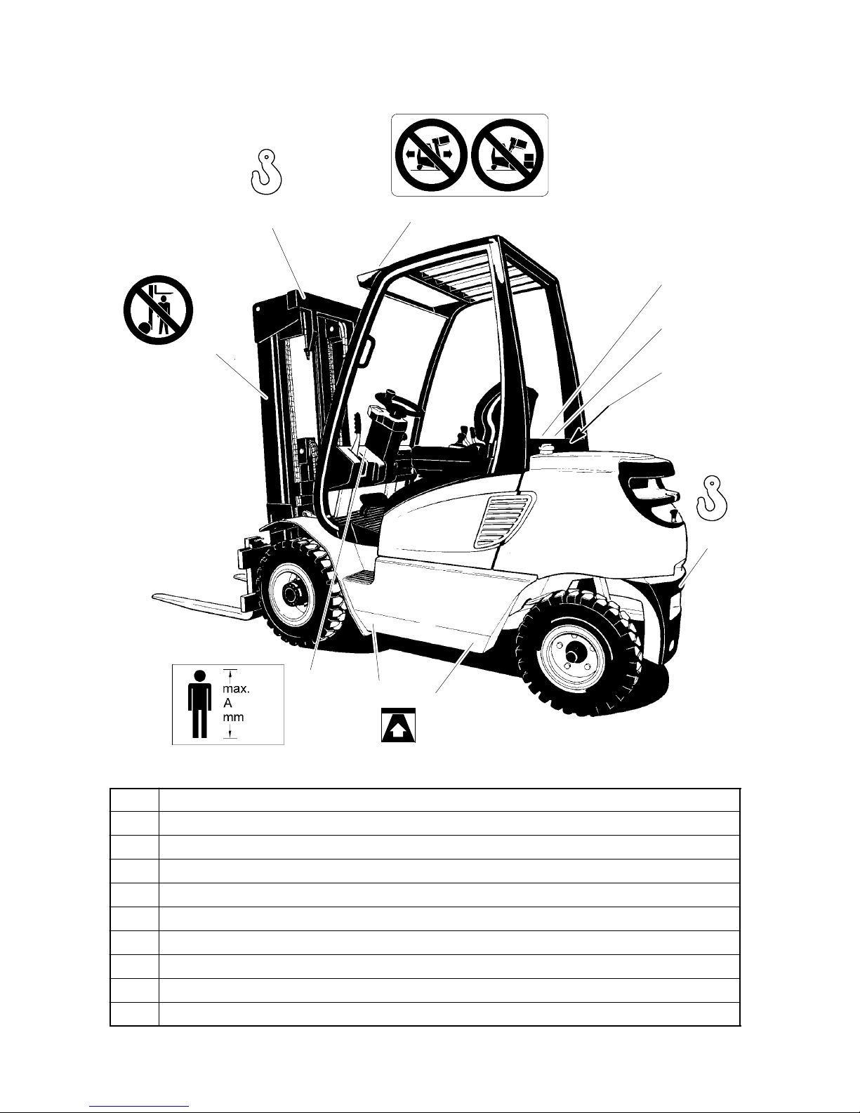
B23
1206.GB
4 Labels and Plates
15
16
17.1
18
19
20
16
21
21
17.2
22
Item. Description
15 Prohibition plate “No standing under load platform”
16 Attachment points for crane loading
17.1 Prohibition plate “No driving with load raised”
17.2 Prohibition plate “No tilting mast forwards with raised load”
18 Load diagram, load forks, load--bearing capacity/centre of gravity/lifting height
19 Load diagram, side loaders, load--bearing capacity/centre of gravity/lifting height
20 Truck rating plate
21 Plate for truck jacking points
22 Plate ”Max. body size”
Page 31

B24
1206.GB
4.1 Truck Rating Plate
23
24
25
26
27
28
29
30
31
32
Item Description Item Description
23 Model 28 Manufacturer
24 Serial number 29 Dead weight in kg
25 Rated capacity in kg 30 Centre of gravity interval in mm
26 Rated drive power in kW 31 Year of construction
27 Manufacturer logo 32 Option
For queries on the truck or for ordering spare parts, please quote the serial number
(24).
A
Page 32

B25
1206.GB
4.2 Load diagrams
Load Diagram Load Forks (Load--Bearing Capacity, Centre of Gravity, Lifting
Height)
The load forks load diagram (35) gives the load--bearing capacity Q of the load forks in
kg. It is given in table form and is dependent on the load centre of gravity D (in mm) and
required lift height H (in mm). Arrow markings (37 and 38) on the inner and outer mast
show the driver when he has reached the lifting height limits given in the load diagram.
35
37 38
Example for Determining Maximum Load--bearing Capacity:
For a load centre of gravity D of 600 mm and a maximum lifting height H of 1100 mm, the
maximum load--bearing capacity Q is 1490 kg.
Load Diagram (Load -- b earing Capacity, Load Centre of Gravity, L ifting Height)
The load diagram (36) gives the load--bearing capacity Q of the side loader in kg. It is
shown in the same form as the load--bearing capacity of the forks and should be
determined accordingly.
36
Page 33

Page 34

C1
0704.GB
C Transportation and Commissioning
1 Transportation
Dimensions
For truck dimensions, refer to the Standard Specifications Sheet(s).
Weights
For truck weight refer to the Standard Specification Sheet(s).
Centre of gravity
Refer to (1) for the centre of gravity of the Frontlift truck. For further information or
advice regarding centre of gravity, contact the manufacturer or trained manufacturer
representative. Refer to (2) for truck lifting points.
Figure 1 Centre of Gravity (Typical)
2
2
1
Securing the truck
It is recommended that the transporting of the truck by road, rail or sea, may only be
undertaken by an authorized transport company.
All trucks being transported by road, rail, or sea have a common method of stowage,
which reduces the possibility of damage to the truck and paintwork.
A typical method of securing the truck to the deck of the lorry, rail truck or ship is to:
S secure the rear of the truck by means of a chain from the towing point in the
counterweight to a convenient deck bolt.
S apply a strap across the floor plate of the truck to a convenient deck bolt.
Ensure that the strap and chain are under tension, see Figure 2.
The chassis will be secured with the mast tilt in the fully back position.
Generally, trucks are transported complete, i.e. with the forks and mast mounted on the
truck. For trucks with mast and forks removed, the following guidelines may be
followed. If in doubt, consult your authorised transport company.
Securing of Mast.
Where machines are being transported with the mast fitted into the truck, no action is
required.
Page 35

2
Figure 3 Securing Mast
3
4
C2
0704.GB
Figure 2 Securing of Chassis (Typical)
Where it is necessary to remove the mast during transportation the following procedure
will be undertaken:--
S Remove forks from carriage and
action, as securing of forks below.
S Remove mast and carriage assembly
from truck.
S Weld securing bar (3) across bottom
of mast and carriage, to prevent
movement of mast and carriage
assembly or where holes are
available, fit bolt (2) through masts
and carriage, and retain witha nut (4).
S Where possible, and in particular with
high lift masts, the lift chain is to be
lightly banded to the lift cylinder, at
not less than 1 metre intervals to
ensure that the chain does not slap
during transportation.
S Thick card or rubber is to be laid between the chain and the lift cylinder, and all
around the cylinder where banding is taking place, to protect the paintwork.
Where it is impracticable to retain the chain as above, the free end is to be wired to a
suitable position, and care taken to ensure paintwork is not damaged during
transportation.
Other than the welding specified in Figure 3 above, no welding is to take place on the
carriage stiles and the mast channels.
A
Page 36

Figure 4 Forks
Banding Material
Fork Stowage Brackets
Figure 5 Securing Forks
Figure 6 Securing Forks
Figure 7 Crane Hook Label
C3
0704.GB
Securing Forks.
Each pair of forks will be securely
banded together using banding
material as shown in F igure 4.
Securing Forks -- Mast Assembly in
Truck.
The forks having been banded together
will be offered up to the mast/carriage
assembly and laid on the fork stowage
brackets which would have been
previously hooked onto the carriage.
The a ssembly will then be securely
banded to the carriage, see Figure 5.
Securing Forks -- Mast Assembly Out
of Truck.
The forks having been banded together
will be offered up to the mast/carriage
assembly. Banding material is passed
under the mast channels and over the
forks, and securely connected, see
Figure 6.
Electrical and hydraulic connections
All electrical connections which are left
disconnected are to be capped, while
disconnected hydraulic connections are
to be plugged.
Slinging
Some of the suitable lifting points for the
truck are indicated by the crane hook
label shown in Figure 7; these lifting
points are situated on the mast and
counterweight.
For further information or advice
regarding suitable lift points for the truck
contact the manufacturer or their
authorised representative.
Page 37

C4
0704.GB
Ensure that all lifting tackle has a S.W.L. suitable for the truck unladen weight.
Before any lifting attempt is made, check that the mast is in the vertical position.
Lifting the truck.
Attach suitable lifting tackle to the trucks lifting points (2).
S Place packing material to avoid damage to truck finish, where lifting tackle is likely
to contact truck.
S Take up the slack and stand clear of the truck.
S Make a test lift, just clear of the ground, to ensure that the lift is square and even,
if not lower to ground and adjust lifting tackle as required.
S If the above are all correct then proceed with the lifting of the truck to the required
position, with slow and definite movements.
S Lower to the required position and remove lifting tackle.
2 Commissioning
Commissioning of the truck may only be carried out by the manufacturer or trained
manufacturer representative.
Lifting equipment required
Chains and shackles capable of handling the weight of the truck -- refer to specification
sheet for weight of truck.
Crane or hoist capable of handling the weight of the truck -- refer to specification sheet
for weight of truck.
Commissioning
Commissioning of the truck may only be carried out by a competent engineer.
Commissioning usually takes the form of performing static and functional checks.
Static and functio nal checks
Static and functional checks are to be carried out by a competent engineer upon
delivery of truck. The checks to be made fall into two broad groups i.e. static and
functional.
A
Page 38

C5
0704.GB
Static Checks.
Static checks to be made are as follows:
o 1. Conforms to ordered specification.
o 2. No transport damage.
o 3. Check paintwork--no corrosion evident.
o 4. Coolant level.
o 5. Oil level--engine.
o 6. Oil level-- transmission.
o 7. Oil level-- hydraulic tank.
o 8. Oil level-- drive axle hubs/differential.
o 9. Oil level--brake/inching master cylinder.
o 10. Air filter and trunking.
o 11. Breather --hydraulic tank.
o 12. Adjustment--fan belt/alternator belt.
o 13. Adjustment and lubrication of lift chains.
o 14. Check--axle mounting bolts.
o 15. Check tightness--wheel nuts.
o 16. Check all tyre pressures.
o 17. Manuals --tools received.
Functional Checks.
The functional checks must be carried out by the competent engineer with the truck
under load, these include:
S Move the truck forward at low speed, change to reverse, and change to forward
again to verify that the direction change mechanism operates effectively.
S Drive the truck forward and rearward through all speed ranges to the maximum
speed, and check that range changing and service brakes operate in both directions.
S Complete several circuits in a figure--of--eight, at approximately one third maximum
speed, in both forward and reverse directions.
S Raise the test load from ground level and elevate it to maximum height. Lower test
load to ground level at maximum speed, making several stops during descent and
deposit load on the ground.
Page 39

C6
0704.GB
C6
0704.GB
Page 40

D1
0704.GB
D Truck Refuelling
1 Safety Conditions for Handling Diesel Fuel and Liquid Petroleum Gas
Before filling up or changing the gas bottle, the truck must be safely parked (see
Chapter E, Section 5.8).
Fire Protection Measures: When dealing with fuels and liquid gas, no smoking, naked
flames or other sources of ignition are permitted within the vicinity of the tank. Signs
indicating the risk zone must be arranged to be clearly visible. Storage of highly
flammable materials in this area is not permitted. Functioning fire extinguishers must
be available to hand in the filling area at all times.
To prevent liquid gas burns, use only carbon dioxide dry extinguishers or carbon
dioxide gas extinguishers.
Storage and Transport: The equipment for storing and transporting diesel fuel and
liquid gas must comply with legal requirements. If no supply point is available, the fuel
must be stored and transported in clean approved vessels. The content must be clearly
marked on the container. Leaking gas bottles must immediately be moved to the open
air, stored in well--ventilated locations and reported to the supplier.Escaping diesel fuel
must be absorbed by suitable agents and disposed of in accordance with the relevant
environmental protection laws.
Staff for Filling Up and Changing Gas Bottles: Staff dealing with liquid petroleum
gas are obliged to have appropriate knowledge on the properties of liquid gas to ensure
safe performance of the work.
Filling Liquid Gas Tanks: Gas tanks remain connected to the truck and are filled at
gas filling points. During filling, the regulations of the filling station and tank
manufacturers and the legal and local conditions must be observed.
Liquid gas causes frost wounds on exposed skin.
f
f
Page 41

1
09/03 and later (540--550)
2
D2
0704.GB
2 Filling with Diesel Fu el
The truck may be filled only at the
specified locations.
S Park the truck securely before filling
(see Chapter E, Section 5.8).
S Open the filler cap (1).
S Fill with clean diesel fuel.
Do not overfill the tank.
Filling quantity:
DFG 316/320: 42 litres.
DFG 420-- 430: 58 litres.
DFG 540-- 550: 70 litres.
Use only diesel fuel DIN 51601 with a
cetene number under 45.
The fuel level display (2) indicates the
fuel level. When the indicator enters the
red, the tank must be filled up.
Never the run the fuel tank empty. Air in
the fuel system can cause operating
faults.
S Close the filler cap again firmly after
filling up.
f
A
Page 42
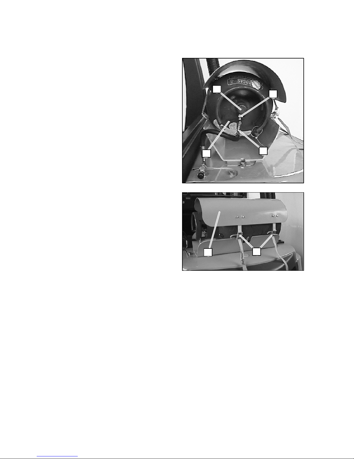
D3
0704.GB
3 Changing the Gas Bottle
The gas bottle may be changed only at the specified locations by trained and
authorised persons.
S Park truck securely before filling (see
Chapter E, Section 5.8).
S Close shut--off valve (3) tightly.
S Start engine and run gas system until
empty in neutral.
S Unscrew nut (4) with a suitable
wrench, holding with the handle (6).
S Remove hose (5) and immediately
screw the valve cover cap onto the
empty gas bottle.
S Release the straps (8) and remove
the cover panel (7).
S Carefully remove the gas bottle from
its holder and deposit securely.
Only 18 kg (29 litres) gas bottles should
be used.
S Place the new gas bottle in the holder
and turn until the connections on the
shut--off valve point downwards.
S Attach the gas bottles securely with
the straps.
S Re--attach the hose as specified.
S Carefully open the shut--off valve and
test the connection for leaks using a
foaming agent.
f
3
4
5
6
3
4
5
6
f
787
8
Page 43

9
10
11
D4
0704.GB
f Refillable liquid petroleum gas bottles
The refillable L.P. Gas bottles are
available in two forms -- ‘end fill’ and
‘centre fill’. Both types of bottle are fitted
with an automatic fill stop valve to
prevent the bottle from being over filled.
Refill the L.P. Gas bottles as follows:
End fill L.P. Gas bottle
Unscrew cap (9). Insert nozzle from L.P.
Gas pump into the fill connector (10). Fill
the L.P. Gas bottle until the liquid level
gauge indicates the bottle is full.
Remove nozzle and refit cap (9).
Centre fill L.P. Gas bottle
Remove cover (11). Unscr ew cap (12).
Insert nozzle from L.P. Gas pump into
the fill connector. Fill the L.P. Gas bottle
until the liquid level gauge indicates the
bottle is full. Remove nozzle and refit
cap (12).
OBSERVE ANY
GUIDELINES/REGULATIONS
RELATED TO THE FILLING OF L.P.
GAS BOTTLES THAT MAY BE FOUND
AT THE L.P. GAS PUMP.
12
f
Page 44

D5
0704.GB
4 Trucks fitted with Twin-- Gas Bottles
Tr ucks fitted with twin--gas bottle arrangement have a lock --valve which can be used
in one of two ways:
S With both LPG cylinder supply valves open, this will increase the overall fuel
capacity.
S With one LPG cylinder supply closed to provide a reserve cylinder.
The following points must be noted to ensure safe operation:
S At no time should the system operate with either of the cylinders disconnected.
S The plastic dust cover on the hydrostatic relief valve should be kept on during
service to keep out contaminants, and inspected regularly.
S If the second cylinder is to be used as a reserve, it must be turned off at the valve
and manually turned on when the service cylinder becomes exhausted.
S For safety reasons, when the service cylinder has exhausted and the reserve
opened, the valve on the exhausted cylinder should then be closed.
S If both cylinders are to be used simultaneously and the cylinder pressures are
unequal, the connector will draw LP--Gas from the cylinder with the higher
pressure until both cylinder pressures equalise. Then the gas will be drawn from
both cylinders.
S If the hose from one of the cylinders were to burst, the connector stops the flow
of gas from the other cylinder, (which prevents both cylinders from emptying).
f
Page 45

Page 46

E1
1206.GB
E Operation
1 Safety Regulations Governing the Operation of the Forklift Truck
Driving permission: The forklift truck must only be operated by persons who have
been trained in the operation of trucks, who have demonstrated to the user or his
representative their capability of moving and handling loads, and who have expressly
been charged by the user or his representative with the operation of the truck.
Rights, duties and conduct of the driver: The driver must be: informed of his rights
and duties; trained in the operation of the forklift truck; and familiar with the contents of
these operating instructions. All necessary rights must be granted to him.
For industrial trucks used in busy areas, safety shoes must be worn during operation.
Prohibition of unauthorized use: The driver is responsible for the forklift truck during
working time. He must forbid unauthorized persons to drive or operate the forklift truck.
The transport or lifting of persons is forbidden.
Damage and defects: Damage or defects noted on the forklift truck or on the
attachments must immediately be brought to the notice of the person in charge. Forklift
trucks that cannot be safely operated (e.g. due to worn tyres or defective brakes) must
not be used until they have been properly repaired.
Repairs: Without specific training and express authorization the driver is not allowed
to perform any repairs or modifications on the forklift truck. Under no circumstances
must the driver change the setting of switches or safety installations, or render them
ineffective.
Danger area: The danger area is considered the area within which persons are
endangered by the travelling or lifting movements of the forklift truck or its load lifting
devices (e.g. fork or attachments), or by the loads being transported. This includes also
the area within reach of dropping loads or dropping truck attachments.
Unauthorized persons must be asked to leave the danger area. The driver must give
a warning signal, whenever a situation presenting danger to persons might develop.
The forklift truck m ust immediately be brought to a standstill, if persons, although
asked, do not leave the danger area.
Safety devices and warning labels: The safety devices, warning labels and warning
notes described in the present operating instructions must always be heeded.
Before operating the truck, the operator must be fully conversant with the arrangement
of the gauges and controls.
Tr ucks with reduced headroom are equipped with a warning sign within the driver’s line
of sight. The max. recommended body size indicated on this sign must be observed.
f
f
Page 47
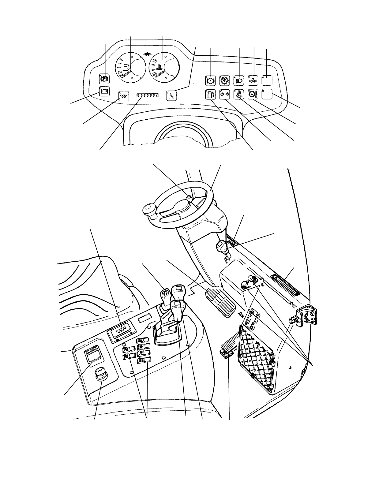
E2
1206.GB
A O -- 1 7 8 -- 2
19
20
22
23
21
24
25
18
27
28
29
30
31
26
19
1
2
3
4
5
6
7
8
9
10
11
12
13
14
15
16
17
E2
1206.GB
A O -- 1 7 8 -- 2
19
20
22
23
21
24
25
18
27
28
29
30
31
26
19
1
2
3
4
5
6
7
8
9
10
11
12
13
14
15
16
17
Page 48

E3
1206.GB
2 Description of Drivers Controls and Display Elements
Item
Control or Display
Element
Function
1
P
Parking brake warning light F
When lit indicates that the parking brake
is operated
2 Fuel gauge (DFG) F Shows the fuel left in the tank
3 Coolant temperature gauge F Shows the coolant temperature
4
N
Neutral F
When lit indicates that the direction switch
is in neutral
5 Brake fluid warning light f
When lit indicates that the brake fluid level
is too low
6
Not used on Hydrokinetic
trucks
7 Lights f
Shows that the front headlights are
switched on
8
Engine oil pressure warning
light
F
When lit indicates insufficient oil p ressure
in the engine
9 Blank f
10 Blank f
Page 49

E4
1206.GB
A O -- 1 7 8 -- 2
19
20
22
23
21
24
25
18
27
28
29
30
31
26
19
1
2
3
4
5
6
7
8
9
10
11
12
13
14
15
16
17
E4
1206.GB
A O -- 1 7 8 -- 2
19
20
22
23
21
24
25
18
27
28
29
30
31
26
19
1
2
3
4
5
6
7
8
9
10
11
12
13
14
15
16
17
Page 50

E5
1206.GB
Item
Control or Display
Element
Function
11
Converter temperature
warning light
F
When lit indicates that the oil temperature
in the load gears is too high
12 Safety belt warning light f
When lit indicates that the safety belt is
not properly fastened
13 Direction indicator LED f
Shows the function of the right/left direction indicator
14 Fuel warning light (DFG) F Indicates low fuel level when lit
15 Time/operating hours display F
Shows the time or operating hours
worked.
16 Preglow control light (DFG) F
Shows the function of the cold start
device
17 Charge current warning light F
When lit indicates that the battery is not
charged
18 Steering wheel F Steers truck in required direction
19 Heating/air outlets f
20
Steering column adjustment
lever
F Adjusts steering column angle
E5
1206.GB
Item
Control or Display
Element
Function
11
Converter temperature
warning light
F
When lit indicates that the oil temperature
in the load gears is too high
12 Safety belt warning light f
When lit indicates that the safety belt is
not properly fastened
13 Direction indicator LED f
Shows the function of the right/left direc-
tion indicator
14 Fuel warning light (DFG) F Indicates low fuel level when lit
15 Time/operating hours display F
Shows the time or operating hours
worked.
16 Preglow control light (DFG) F
Shows the function of the cold start
device
17 Charge current warning light F
When lit indicates that the battery is not
charged
18 Steering wheel F Steers truck in required direction
19 Heating/air outlets f
20
Steering column adjustment
lever
F Adjusts steering column angle
Page 51

E6
1206.GB
DFG/TFG 540--550
E6
1206.GB
DFG/TFG 540--550
Page 52

E7
1206.GB
Item
Control or Display
Element
Function
21 Cab heater Controls f
22 Accelerator pedal F
Controls engine speed or drive and travel
speed
23 Raise/lower control lever F
Raises or lowers fork carriers.
Raise fork carrier: pull lever back.
Lower fork carrier: push lever forwards.
24 Mast tilt control lever F
Tilt mast forwards or backwards.
Tilt mast forwards: push lever forwards.
Tilt mast backwards: pull lever backwards.
25 Switch(es) f Lights, demister etc.
26 Ignition/starter switch F
Connects and disconnects the power
supply.
Starts and stops engine. When the ignition key is removed, the truck is protected
from use by unauthorised persons.
27
Battery isolation switch
(emergency off)
F
The main power circuit is cut, all electrical
functions are disconnected.
Thetruckrollstoastop
This switch should only be used to stop in
an emergency or for isolation purposes. If
switch is activated, reset clock (20) and
(21). Under normal conditions the
stopping instructions on page E 24 must
be followed.
28 Warning signal button F Triggers an acoustic warning signal
29 Direction lever F Selects direction of travel
30
Creep/brake pedal (From
02/07 DFG/T F G 316--430
only)
F
1st range: controls creep drive
2nd range: activates operating brake
31
Parking br ake lever
(09/03 and later: to the
steering wheel right in the
540--550 series)
F
Applies or releases the parking brake:
Pull lever to engage.
Push lever forwards to release.
32
Brake pedal (from 02/07
DFG/TFG 540--550 only)
F The truck’s brake is applied.
33
Slow travel / brake pedal
(from 02/07 DFG/TFG
540--550 only)
F
1st range: controls creep drive
2nd range: activates operating brake
E7
1206.GB
Item
Control or Display
Element
Function
21 Cab heater Controls f
22 Accelerator pedal F
Controls engine speed or drive and travel
speed
23 Raise/lower control lever F
Raises or lowers fork carriers.
Raise fork carrier: pull lever back.
Lower fork carrier: push lever forwards.
24 Mast tilt control lever F
Tilt mast forwards or backwards.
Tilt mast forwards: push lever forwards.
Tilt mast backwards: pull lever backwards.
25 Switch(es) f Lights, demister etc.
26 Ignition/starter switch F
Connects and disconnects the power
supply.
Starts and stops engine. When the igni-
tion key is removed, the truck is protected
from use by unauthorised persons.
27
Battery isolation switch
(emergency off)
F
The main power circuit is cut, all electrical
functions are disconnected.
Thetruckrollstoastop
This switch should only be used to stop in
an emergency or for isolation purposes. If
switch is activated, reset clock (20) and
(21). Under normal conditions the
stopping instructions on page E 24 must
be followed.
28 Warning signal button F Triggers an acoustic warning signal
29 Direction lever F Selects direction of travel
30
Creep/brake pedal (From
02/07 DFG/T F G 316--430
only)
F
1st range: controls creep drive
2nd range: activates operating brake
31
Parking br ake lever
(09/03 and later: to the
steering wheel right in the
540--550 series)
F
Applies or releases the parking brake:
Pull lever to engage.
Push lever forwards to release.
32
Brake pedal (from 02/07
DFG/TFG 540--550 only)
F The truck’s brake is applied.
33
Slow travel / brake pedal
(from 02/07 DFG/TFG
540--550 only)
F
1st range: controls creep drive
2nd range: activates operating brake
Page 53

E8
1206.GB
f Gimbal -- lift and tilt
Gimbal functions
1
2
3
5
6
7
8
4
Gimbal
Ancillary Control Levers
A0--178
Symbol Purpose Symbol Purpose
1. To tilt the mast forward.
5. To tilt the mast backward.
2. To lift the fork tines and
tilt the mast forward.
6. To lower the fork tines
and tilt the mast backward.
3. To lift the fork tines. 7. To lower the fork tines.
4. To lift the fork tines and
tilt the mast backward.
8. To lower the fork tines
and tilt the mast forward.
On some models, these functions may be disabled.
E8
1206.GB
f Gimbal -- lift and tilt
Gimbal functions
1
2
3
5
6
7
8
4
Gimbal
Ancillary Control Levers
A0--178
Symbol Purpose Symbol Purpose
1. To tilt the mast forward.
5. To tilt the mast back-
ward.
2. To lift the fork tines and
tilt the mast forward.
6. To lower the fork tines
and tilt the mast back-
ward.
3. To lift the fork tines. 7. To lower the fork tines.
4. To lift the fork tines and
tilt the mast backward.
8. To lower the fork tines
and tilt the mast for-
ward.
On some models, these functions may be disabled.
Page 54

III
E9
1206.GB
F Gear selector
With the gearshift lever in the central
position, the transmission is in neutral.
S To select forward gear, push lever
forwards.
S To select reverse gear, pull lever
backwards.
The engine will not start if the truck is in
gear.
F Two speed gear selector
-- DFG/TFG 540--550
Gear selection is operated manually,
press ‘I’ to select a lower gear when
climbing or descending an incline.
f Column mounted gear selector
On trucks fitted with a gimbal lever (refer
to page E 8 ), the standard gear selector
fitted to the right of the driver’s seat is
replaced by a column mounted gear
selector.
With the gearshift lever in the central
position, the transmission is in neutral.
S To select forward gear, push lever
forwards.
S To select reverse gear, pull lever
backwards.
The engine will not start if the truck is in
gear.
A
A
A
A
Page 55

41
42
43
E10
1206.GB
f Gear Interlock System -- TFG/DFG 540--550
The Gear Interlock System is an option
preventing the operator to drive the
truck from a standstill position if the
truck is in gear. The System will also
prevent the operator from changing
direction if the truck is in second gear.
It is important to note that while the truck
may coast during gear changing,
braking is still available.
f Cab Heater controls
S Turn the thermostat control knob (41)
anti--clockwise to progressively to
lower the cab temperature.
S Turn the fan control knob (42)
clockwise to r egulate the fan air flow.
To switch off, turn the fan control knob
fully anti--clockwise.
S Slide the air flow direction lever (43)
down to its lowest position to direct air
flow to the cab floor. Slide the air flow
direction lever (43) to its upper
position to cut off the air flow to the
cab floor. The air flow to the front
screen is controlled independently of
this lever by the vents in the plastic
ducting along the bottom of the
screen.
A
Page 56

25
43
44
TFG 316/320
MAX.
MIN.
E11
1206.GB
Horn
S Press button (25) to sound the horn.
3 Checks and Activities Before Daily Use
Truck
S Check complete truck (in particular wheels and load--carrying means) for visible
damage.
With exception of ‘checking the windscreen washer level’, all checks will require the
opening of the service doors and covers: refer to page E 43 Engine Housing.
Checking engine oil level -- TFG
S Withdraw dipstick (44 or 46 or 48).
S Wipe the dipstick with a lint-free cloth
and re-insert into the hole to its fullest
extent.
S Withdraw the dipstick again and
check the oil level is between the MIN
and MAX marks.
S If below m id point, remove filler cap
(43 or 45 or 47) and add the correct
type of oil to the engine until the level
is indicated at the MAX mark on the
dipstick.
A
Page 57

46
TFG 420--430
45
MAX.
MIN.
48
47
TFG 540--550
MAX.
MIN.
50
49
DFG 316/320
MAX.
MIN.
E12
1206.GB
Checking engine oil level -- DFG
S Withdraw dipstick (50 or 52).
S Wipe the dipstick with a lint-free cloth
and re-insert into the hole to its fullest
extent.
46
TFG 420--430
45
MAX.
MIN.
48
47
TFG 540--550
MAX.
MIN.
50
49
DFG 316/320
MAX.
MIN.
E12
1206.GB
Checking engine oil level -- DFG
S Withdraw dipstick (50 or 52).
S Wipe the dipstick with a lint-free cloth
and re-insert into the hole to its fullest
extent.
Page 58

52
51
DFG 420-- 550
MAX.
MIN.
53
DFG/TFG 316/320
54
DFG/TFG 420--430
E13
1206.GB
Withdraw the dipstick again and check
the oil level is between the MIN and
MAX marks.
S If below m id point, remove filler cap
(49 or 51) and add the correct type of
oil to the engine until the level is
indicated at the MAX mark on the
dipstick.
Checking the h yd raulic oil level
If oil is cold
S Operate mast by fully raising and
lowering, once.
S Switch off engine.
S Withdraw the dipstick (53 or 54 or 55)
and clean it using a clean cloth.
Check hydraulic oil level. The level
must be between the minimum and
maximum marks on the dipstick. Top
up, if necessary, to the MINIMUM
mark on the dipstick.
Page 59

55
DFG/TFG 540--550
H
L
MAX.
MIN.
DFG/TFG 316/320
MAX.
MIN.
DFG/TFG 420--550
E14
1206.GB
If oil is hot
S Operate mast by fully raising and
lowering, once.
S Switch off engine.
S Withdraw the dipstick (53 or 54 or 55)
and clean it using a clean cloth.
Check hydraulic oil level. The level
should be just above the maximum
mark on the dipstick. Top up, if
necessary, to just above the
MAXIMUM mark on the dipstick.
In the event of the engine stalling or
cutting out with the mast raised, lower
the mast slowly before continuing with
the procedure.
A
Page 60

56
E15
1206.GB
Checking the coolant level
S Check the coolant level in the
expansion tank (56).
The coolant level must be between the
‘MIN’ and ‘MAX’ marks.
If the coolant level has dropped below
the ‘MIN’ mark, this is a sign that the
cooling system is leaking. The truck
must only be operated again, after the
fault has been rectified.
WHEN THE ENGINE IS HOT THE
COOLANT SYSTEM IS
PRESSURISED AND THE
EXPANSION TANK CAP SHOULD BE
OPENED SLOWL Y, UNTIL ALL
PRESSURE IS RELEASED.
When replenishing, add a pre--mixed solution of water and anti--freeze of the same
proportions as that already in the system.
The system should be drained by opening the drain cock in the radiator and on the side
of the cylinder block. These may be brass type plugs. Remove the expansion tank cap
when draining and put the cap on the driver’s seat as a warning that the engine contains
no coolant.
Where anti--freeze is not used, a suitable corrosion inhibitor must be mixed into the
coolant.
For recommended concentrations and safety precautions refer to Para. 7 Chapter F.
Checking the fuel level -- (DFG)
S Turn ignition/starter switch (26) to
position 1 .
S Establish fuel supply on the fuel
supply display (2).
S If necessary fill up with diesel fuel
(see Chapter D, Section 2).
f
26
2
Page 61

09/03 and later (540--550)
E16
1206.GB
Checking the windscreen washer
level
S Check that there is sufficient
windscreen washer fluid in the bottle;
refill if necessary.
S Use anti-freeze windscreen washer
fluid, eg. methylated spirits.
Wheels and tyres
S Check wheels and tyres for wear
(refer to chapter F). Check tyre
pressures (pneumatic tyres only), -refer to technical data, chapter B.
09/03 and later (540--550)
E16
1206.GB
Checking the windscreen washer
level
S Check that there is sufficient
windscreen washer fluid in the bottle;
refill if necessary.
S Use anti-freeze windscreen washer
fluid, eg. methylated spirits.
Wheels and tyres
S Check wheels and tyres for wear
(refer to chapter F). Check tyre
pressures (pneumatic tyres only), --
refer to technical data, chapter B.
Page 62
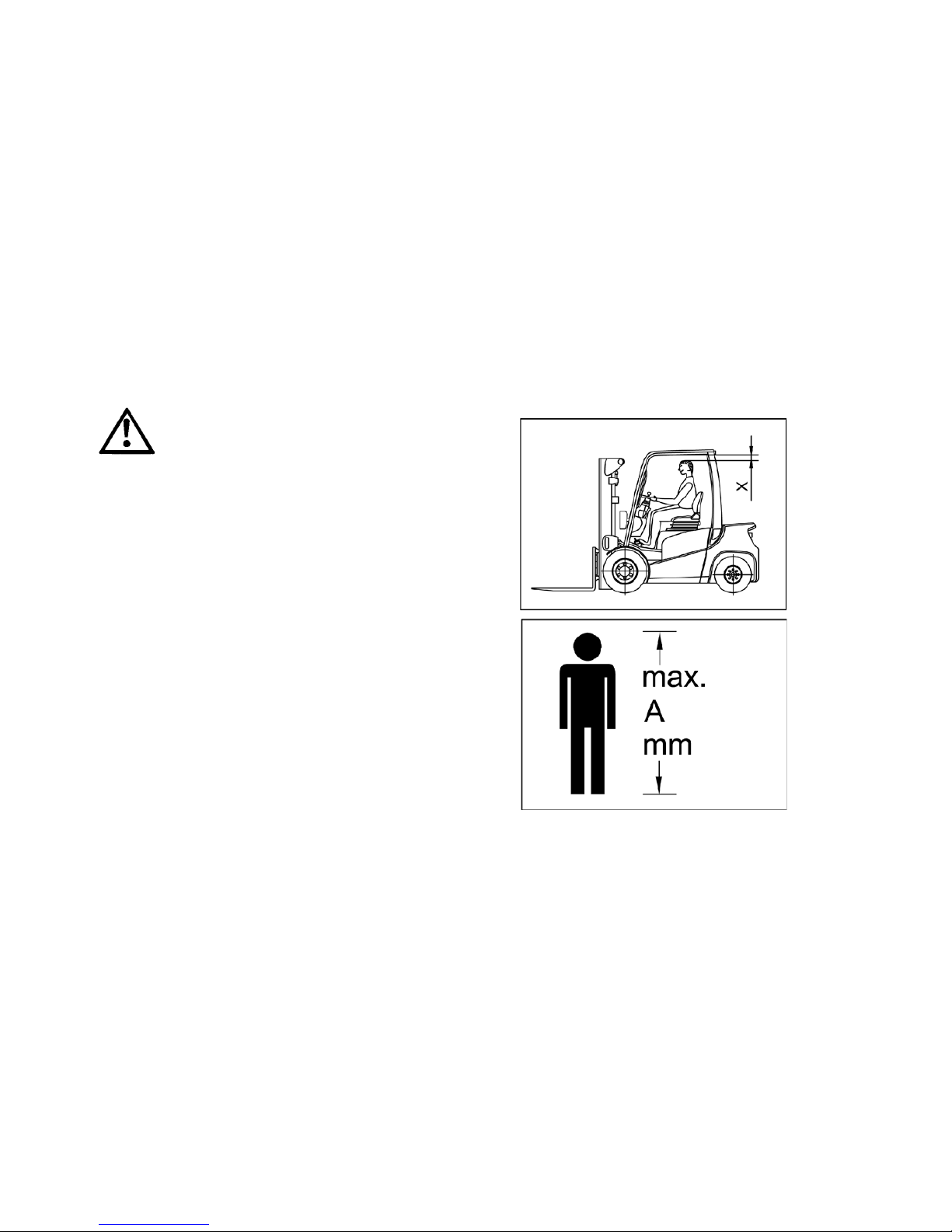
E17
1206.GB
4 Using the Truck
Before using the truck for the first time or before lifting a load, the driver must ensure
that no one is standing in the risk area.
Checks and Activities Before Daily Use
S Check the complete truck (in particular wheels and load carriers) for damage.
S Check that the load chains are evenly tensioned.
S Check the action of the restraint belt buckle and the retraction of the belt into the
retractor: refer to para 5.7 for further information.
Adjust Driver’s Seat
To achieve optimum seat damping, the driver’s seat must be set to the driver ’s weight.
The driver’s seat must be unloaded when set to the driver’s weight.
Trucks with reduced headroom X (o)
Failure to comply with the
recommended body size may result in
overload and constitute a danger to the
driver, possibly resulting in permanent
damage caused by an unhealthy
posture and excessive physical
exertions on the part of the driver.
The owner must ensure that the truck
operator does not exceed the maximum
body size indicated.
The owner must also check that the
drivers can sit normally, in an upright
position without having to exert himself.
f
A
Page 63
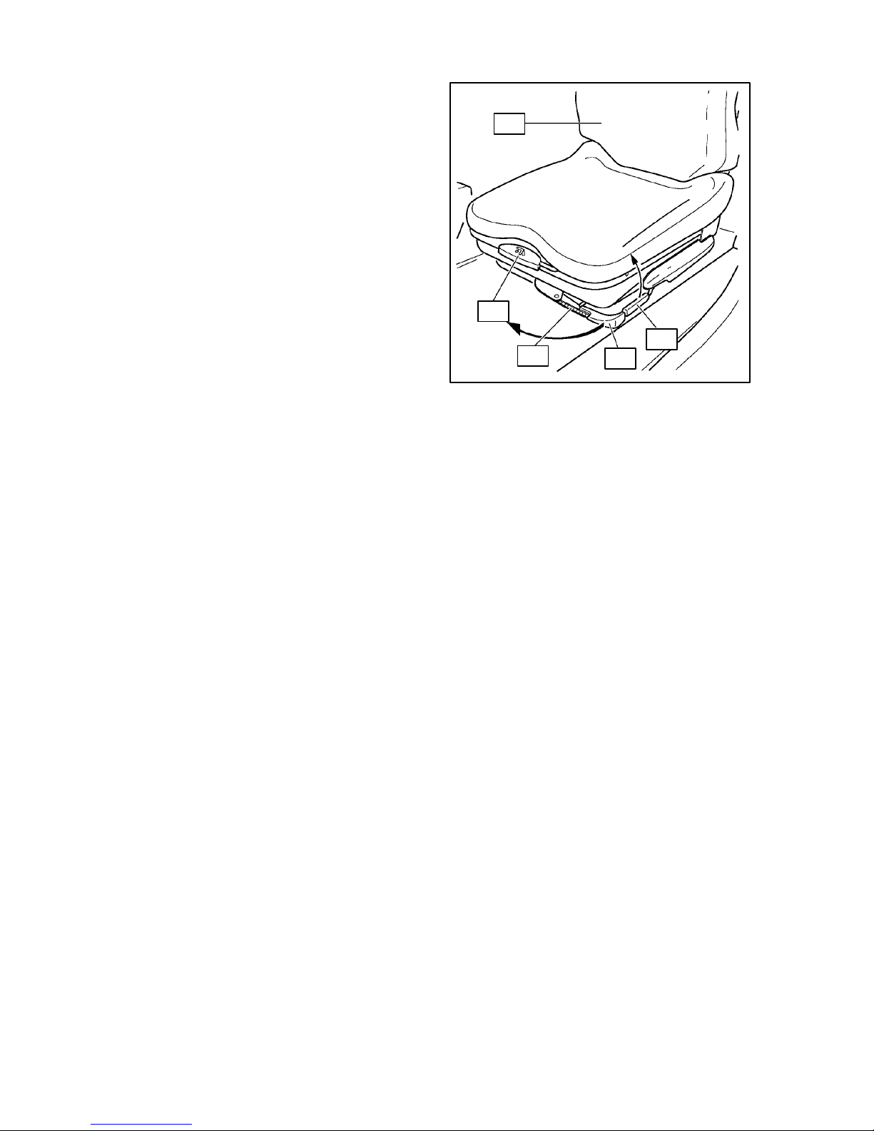
E18
1206.GB
Set Driver’s Weight:
S Pull lever (60) in the direction of the
arrow as far as the stop and return.
The previous weight setting is returned
to minimum. Adjustment range of seat
damping 50 kg to 130 kg.
S Pull lever (60) in the direction of the
arrow again up to the corresponding
weight marking on the scale (61).
Then return the lever.
S Sit on the driver’s seat.
During adjustment, do not reach
between the seat and the engine cover.
Adjust the Backrest:
S Pull locking lever (59) and adjust the angle of the seat backrest (58).
S Release locking lever (59) again, this seat backrest is now locked.
Adjust Seating Position:
S Pull locking lever (57) for seat lock up in the direction of the arrows and move the
seat to the correct position by sliding forwards or backwards.
S Allow the locking lever to lock again (57).
The driver’s seat catch must be securely locked in the set position. The driver’s seat
position must not be changed during use.
The restraint belt should be fastened before the truck is started: refer to para 5.7 for
further information.
The seat adjustment described refers to the standard design. T he adjustment
instructions of the manufacturer must be used for alternative versions. During
adjustment ensure that all controls are easily accessible.
57
58
59
60
61
A
f
f
A
A
Page 64

45
28
F
L
62
20
O
I
II
III
E19
1206.GB
It is essential that the correct weight is selected as this will reduce the amount of
vibration acting upon the driver’s body.
Some trucks may be fitted with a dead man’s switch, i.e. the truck will not start unless
the driver is on the seat.
Steering Column Adjustment.
S Pull the steering column control lever
(20) in the direction of the arrow (L)
towards the driver’s seat.
S Move the steering column (62)
forwards or backwards to the
required angle.
S Push the steering column adjustment
lever in the direction of arrow (F).
Starting the Truck
Pre--Start Precautions.
If an engine has been standing for a month or more, lubricate the rocker shaft, tappets
and valve stems with engine oil and bleed the fuel system.
If the engine has not been run for several weeks, or if the oil filter has been changed,
start the engine, (refer to para 4.1 or 4.2), and let it run at idle speed for a few minutes
before use.
Start Engine
The truck should only be operated from the driver’s seat.
S Apply the parking brake.
Move direction lever (29) to neutral N.
The engine can be started only when the direction lever is in neutral.
For start process TFG, see Section 4.1.
For start process DFG, see Section 4.2.
Key Operated Ignition Switch
Function:
O -- all power circuits off, the key can
be removed.
I -- controls and instruments on.
II -- engine pre-heating (diesel only).
III -- start engine (automatic return to
position II).
A
f
A
A
A
Page 65

29
26
22
28
E20
1206.GB
4.1 Start Process TFG
Note safety conditions when dealing
with LPG (see Chapter D, Section 1).
S Slowly open shut--off valve (63) on
the gas bottle.
S Insert key in ignition/starter switch
(26).
S Turn ignition/starter switch to position
I.
S Activate warning signal button (28)
and check horn for function.
The warning lights for charge current
(17) engine oil pressure (8), neutral (4)
and parking brake (1) light up.
S Press the accelerator pedal (22)
lightly.
S Turn the starter/ignition switch to
position II.
Only operate the starter for max 15
seconds at a time. Before repeating the
start process, return the ignition/starter
switch to position 0 and wait 30 to 60
seconds.
S Release key as soon as the engine
starts. It automatically returns to
position I.
It is important to observe the following safety conditions when dealing with LPG Tr ucks.
If LPG truck does not start:
S Close shut--off valve for gas bottle.
S Turn ignition/starter switch to O.
S Call a trained competent Service Engineer for technical assistance.
S DO NOT remove the plastic cover on the LPG vaporiser.
S DO NOT depress the fuel primer button.
The removal of the plastic cover and the depressing of the fuel primer button must only
be carried out by a trained competent Service Engineer.
Depressing the fuel primer button repeatedly will cause excess fuel to be injected into
the system, thus increasing the risk of fire or explosion!
f
4663
f
Page 66

E21
1206.GB
All warning lights except for neutral (4)
and parking brake (1) must go out as
soon as the engine starts. If this is not
the case, switch off the engine and
repair the fault.
4.2 Start Process DFG
S Insert key in ignition/starter switch
(26).
S Turn ignition/starter switch to position
I.
S Activate warning signal button (28)
and test horn for function.
S When the ignition/starter switch (26)
has been moved to position I,the
warning lights for charge current (17),
engine oil pressure (8), neutral
position (4) and parking brake (1),
and the control light for preglow (16)
light up.
S Press the accelerator pedal (22) fully
and wait for the preglow light to go
out.
The preglow time depends on the
engine temperature and is usually
around 4 seconds.
On DFG 316/320 models, the preglow
light does not extinguish, hence, after 4
seconds, turn starter/ignition switch to
position II.
S Turn the starter/ignition switch to
position II.
Only operate the starter for max 15
seconds at a time. Before repeating the
start process, return the ignition/starter
switch to position 0 and wait 30 to 60
seconds.
S Release the key as soon as the
engine has started. It automatically
returns to position I.
All warning lights except for neutral (4)
and parking brake (1) must go out as
soon as the engine starts. If this is not
the case turn off the engine immediately
and repair the fault.
1
8
4
17
16
25
34
33
29
28
26
A
1
8
4
17
16
A
22
Page 67

E22
1206.GB
After the engine has started, carry out a
test run and the following functions
checks:
S Test brake effect of parking brake
(31) and operating brake (30).
S Control the engine speed with the
accelerator (22) in various ranges,
checking for free movement of the
pedal.
S Check hydraulic control functions for
raise/lower (23), tilt (24) and where
applicable the attachments for
smooth function.
S Turn steering wheel (18) to both end
positions and check steering for
function.
f
22
18
30
31
09/03 and later (540--550)
31
32
23
24
Page 68

E23
1206.GB
Do not run the engine to warm on idle.
The engine quickly reaches its
operating temperature under moderate
load and at varying speeds.
Only apply full load to the engine when
the engine coolant temperature (2)
shows the operating temperature.
When all function tests have been
carried out perfectly and operating
temperature has been reached, the
truck is ready for use.
4.3 Fault Displays during Op eration
If the warning lights for:
S engine oil pressure (8),
S charge current (17),
S coolant temperature (3),
S converter temperature (11),
come on, the engine must be switched
off immediately.
The engine may not be started again
until the fault has been repaired.
For fault search and remedies, see
Section 6.
Check fuel tank display (2, DFG only)
during operation.
2
3
8
11
17
A
Page 69

E24
1206.GB
Switch Off Engine 1.
Do not switch off the engine from full
load but allow to run for a short time to
adjust temperature.
S Stop the truck.
S Move the direction lever (29) to
neutral.
S Activate the parking lever (31).
S Turn the ignition/starter switch (26) to
position 0.
31
26
29
09/03 and later (540--550)
Page 70

E25
1206.GB
5 Operation of the Forklift Truck
5.1 Safety regulations applicable when operating the truck
Driving lanes and work areas: Only such lanes and routes that are specially
allocated for truck traffic must be used. Unauthorized persons must stay away from
work areas. Loads must only be stored at places specially provided for this purpose.
Driving conduct: The travelling speed must be adapted to the prevailing local
conditions. The truck must be driven at slow speed when negotiating bends or narrow
passages, when passing through swing doors and at blind spots. The driver must
always observe an adequate braking distance between the fork --lift truck and the truck
in front and he must be in control of his truck at all times. Sudden stopping (except in
emergencies), rapid U--turns and overtaking at dangerous or blind spots is not
permitted. It is forbidden to lean out of or reach beyond the working and operating area.
Visibility: T he driver must look in the direction of travel and must always have a clear
view of the route ahead. When loads blocking the view are carried, the fork--lift truck
must be driven with the load at the rear. If this is not possible, a second person must
walk in front of the fork-- lift truck to give suitable warnings.
Negotiating slopes and inclines: Negotiating of slopes and inclines is permitted
only, when they are recognized lanes, when they are clean and non--slipping, and when
the technical specification of the truck permits safe driving on such slopes or inclines.
Loads must always be carried at that end of the truck facing uphill. U--turns, cutting
obliquely over slopes or inclines and parking of the fork--lift truck on slopes or inclines is
not permitted. Inclines must only be negotiated at slow speed with the driver ready to
brake at any moment.
Use of lifts and driving on load platforms: Lifts and loading platforms must only be
used, if they are of adequate load bearing capacity, if suitable for driving on, and if
authorized by the user of the truck for truck traffic. The fork--lift truck driver has to satisfy
himself accordingly before driving into lifts or on to loading platforms. The truck must
enter lifts with the load in front and must take up a position which does not allow it to
come into contact with the wallsof the lift shaft. Persons riding in the lift together with the
fork--lift truck must only enter the lift after the fork--lift truck has come safely to a
standstill, and must leave the lift before the fork--lift truck.
Nature of the load carried: Only loads that have been safely and correctly secured
must be carried. Never transport loads stacked higher than the top of the fork carriage,
or stacked higher than the guard grille.
Page 71

E26
1206.GB
To wing of t railers or other vehicles is only allowed occasionally and on paved, level
driveways with a maximum deviation of +/--1% and a maximum speed of 5 km/h.
Permanent trailer operation is not permitted.
While towing, loads are not allowed on the forks.
The maximum trailer load given for the fork lift truck for braked and/or unbraked trailers
must not be exceeded. Th e indicated trailer load is only valid for the auxiliary coupling
at the fork lift truck counterweight. Also heed the instructions of the coupling
manufacturer if the genuine trailer coupling is replaced by another make.
After attaching the trailer but before starting driving, the driver must check that the
trailer coupling is secured against detaching. Towing fork lift trucks must be operated in
such a manner that safe driving and braking of the truck and the trailer is guaranteed for
all driving movements.
Exhaust emissions: Only operate the truck in well ventilated areas. Operating the
truck in confined areas may lead to a build up of harmful exhaust emissions, which may
cause dizziness, drowsiness or even death!
f
Page 72

22
E27
1206.GB
5.2 Driving
Adjust the driving speed to the situation
of the road, working area and load.
S Move the direction lever (29) to
neutral.
S Raise the fork carrier approximately
200 mm so that the load forks are
clear of the ground.
S Tilt the lifting frame fully back.
S Release the parking brake.
Driving Forwards
S Move the direction lever (29)
forwards.
S Press the accelerator pedal (22)
slowly until the required speed is
reached.
Change Direction of Travel
Only change direction of travel when the
truck has stopped.
S Move the direction lever (29) through
neutral to the required direction of
travel.
S Press the accelerator pedal (22)
slowly until the required speed has
been reached.
Reversing
Ensure that the driving area behind you is clear.
S Move the direction lever (29) backwards.
Accelerate Truck
S Slowly press the accelerator (22) until the truck begins to move.
S Press the accelerator further.
The engine speed and drive speed increase.
f
33
29
27
f
Page 73

22
30
E28
1206.GB
Stopping the truck
The braking behaviour of the truck
mainly depends on the ground surface.
The driver must take this into account in
his driving behaviour. Brake the truck
carefully to ensure that the load does
not slip.
Braking
S Remove foot from accelerator (22).
S Lightly press the creep/brake pedal (30).
In the first range of the pedal travel, the force via the torque converter is reduced.
S Press the creep/brake pedal (30) further.
When pressed further, the truck is braked to a standstill using the drum brake.
Creep Drive with Creep/Brake Pedal
When manoeuvring in tight spaces for slow movement, operate the creep/brake pedal
(30) delicately.
This operating mode is permitted for maximum 5 seconds at a high engine speed.
f
Page 74

30
Parking Brake
Disengaged
Parking Brake
Engaged
40
27
31
Parking Brake
Engaged
E29
1206.GB
5.3 Steering
The steering force to be applied is very
low because of the hydrostatic steering,
so turn the steering wheel (18)
delicately.
5.4 Braking
Service brakes
The drum brakes on the front wheels
are controlled hydraulically via the
creep/brake pedal.
S Press the creep/brake pedal (30) until
there is perceptible braking pressure.
The first range of the pedal travel
controls the force flow in the gears.
When the pedal is pressed further,
the drum brakes on the front wheels
are applied.
Parking brake
The parking brake lever mechanically
operates the drum brakes on the front
wheels.
S Pull the parking brake lever (31)
beyond the pressure point to the stop.
The parking brake is engaged and
the brake lever locked in this position.
S Depress button (40) and briefly pull
lever backward to disengage from
ratchet. Push the brake lever forward
over the pressure point to release the
brake.
Thebrakeleverisalsolockedinthe
released position.
26
18
f
Page 75

Parking Brake
Disengaged
Parking Brake
Engaged
E30
1206.GB
Parking brake (09/03 and later (540--550))
The parking brake lever mechanically
operates the drum brakes on the front
wheels.
S Pull the parking brake lever (31)
beyond the pressure point to the stop.
The parking brake is engaged and
the brake lever locked in this position.
S Pull the release lever (40) towards
the brake lever and briefly pull the
locking lever (31) to the rear to
disengage it. Push the brake lever
forward over the pressure point to
release the brake.
Thebrakeleverisalsolockedinthe
released position.
Always apply the parking brake and
switch off the engine before leaving the
truck.
The parking bra ke will hold the truck at its m a xim um permitted load on a clean concrete
surface on a slope of 15%.
A
f
Parking Brake
Disengaged
Parking Brake
Engaged
E30
1206.GB
Parking brake (09/03 and later (540--550))
The parking brake lever mechanically
operates the drum brakes on the front
wheels.
S Pull the parking brake lever (31)
beyond the pressure point to the stop.
The parking brake is engaged and
the brake lever locked in this position.
S Pull the release lever (40) towards
the brake lever and briefly pull the
locking lever (31) to the rear to
disengage it. Push the brake lever
forward over the pressure point to
release the brake.
Thebrakeleverisalsolockedinthe
released position.
Always apply the parking brake and
switch off the engine before leaving the
truck.
The parking bra ke will hold the truck at its m a xim um permitted load on a clean concrete
surface on a slope of 15%.
A
f
Page 76

E31
1206.GB
5.5 Operating the Mast and Attachments
The control lever may only be operated
from the driver’s seat.
The lifting gear is operated with the
control levers to the right of the driver’s
seat.
Raise/Lower Fork Carriage
S Pull the control lever (23) back to
raise the fork carriage.
S Push the control lever (23) forwards
to lower the fork carriage.
Tilt Mast Forwards/Backwards
When the mast is tilted back, do not
insert any body parts between the mast
and the front wall.
S Pull the control lever (24) back to tilt
the m ast back.
S Push the control lever (24) forwards
to tilt the mast forwards.
f Operating an Attachment
Attachments are operated using the
control lever (64) on the right next to
control lever (23) (tilt mast).
When operating an attachment,
observe the manufacturer’s operating
instructions.
24
23
f
f
49
32
64
23
f
Page 77
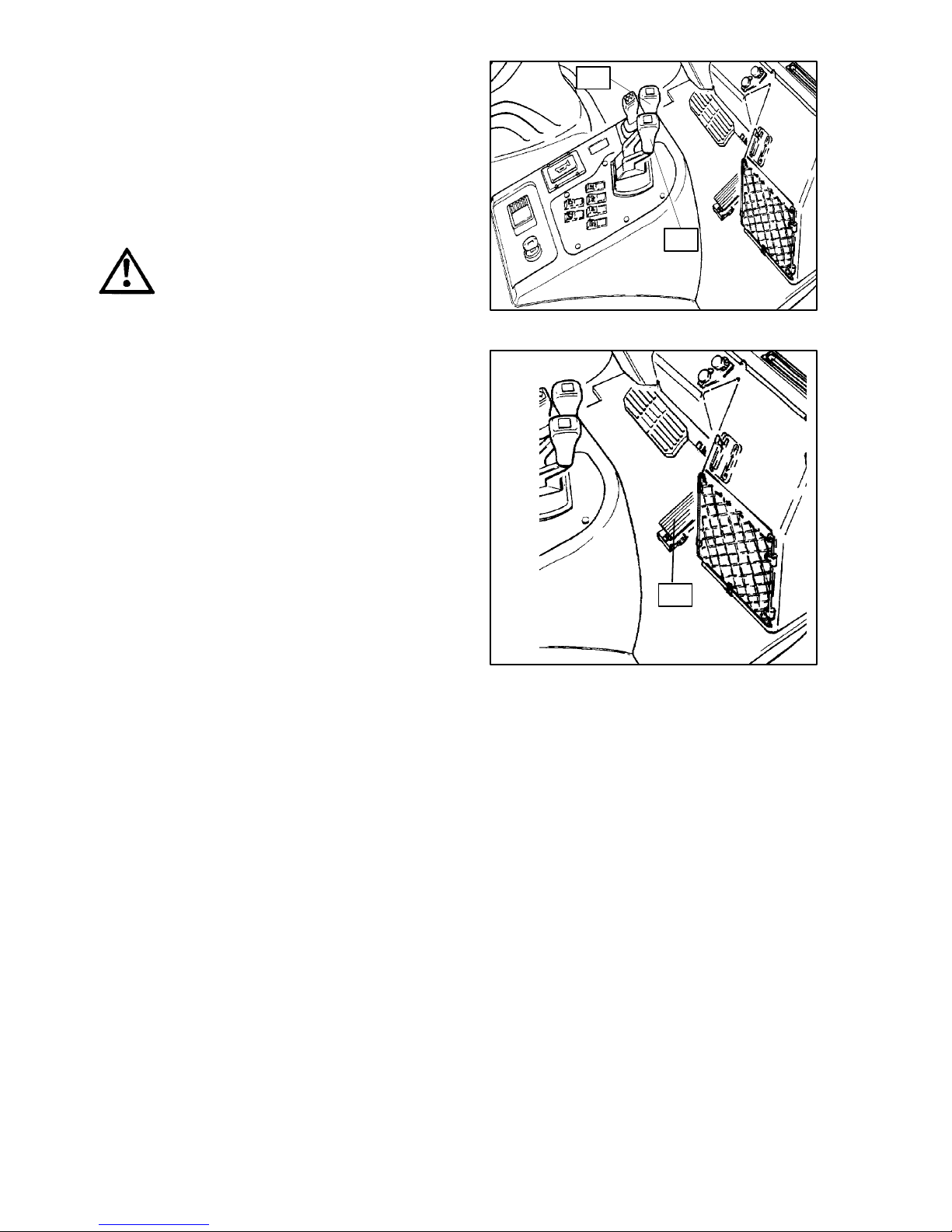
22
E32
1206.GB
Control M ach in e Speed
The working speed of the hydraulic
cylinders is controlled by the extent of
movement of the control levers and the
engine speed.
When the control levers are released
they automatically return to neutral and
the machine locks in the position set.
Always operate the control levers
smoothly and carefully. When reaching
the end stop, release the control levers
immediately.
S Increase engine speed with
accelerator (22) and
S Move the control lever further back to
increase the speed of the machine.
The engine speed has no effect on the
lowering speed of the fork carrier.
Lifting of persons with the lifting gear is
prohibited.
24
23
A
f
Page 78

E33
1206.GB
5.6 Picking Up, Transporting and Setting
Down Load Units
The control levers may be operated only
from the driver’s seat.
Before picking up a load unit, the driver
must ensure that it is properly palleted
and the permitted load-- bearing
capacity of the truck is not exceeded.
Note load diagram!
Adjust Load Forks
The load forks should be adjusted so
that the two arms are at the same
distance from the outer edges of the fork
carrier and the centre of gravity of the
load lies in the centre between the fork
arms.
S Swivel locking lever (65) upwards.
S Slide fork arm (66) on the fork
carriage (67) into the correct position.
S Slide locking lever down and move
the fork arm until it engages in a
groove.
f
65
66
67
f
Page 79

E34
1206.GB
Picking Up the Load
S Carefully approach the load to be
picked up.
S Switch the direction lever (29) to
neutral.
S Apply the parking brake (31).
S Raise the forks to the correct height
for the load.
S Move the direction of travel lever to
forwards and release the parking
brake.
S Carefully move the forks under the
load, if possible until it lies on the back
of the forks.
29
31
09/03 and later (540 --550)
Page 80

E35
1206.GB
The load forks must have at least 2/3 of
their length under the load.
S Move the direction lever (29) to
neutral and apply the parking brake
(31).
S Raise the fork carriers until the load
lies freely on the load forks.
S Switch the direction lever to reverse
and release the parking brake.
Ensure the path is clear behind you.
S Carefully and slowly reverse until the
load is outside the storage area.
f
29
31
f
09/03 and later (540--550)
Page 81

E36
1206.GB
It is prohibited to stand below the raised
load.
S Lower the load as far as possible for
transport (ground clearance approx.
150 to 200 mm).
The higher the load is transported, the
lower the stability.
f
f
E36
1206.GB
It is prohibited to stand below the raised
load.
S Lower the load as far as possible for
transport (ground clearance approx.
150 to 200 mm).
The higher the load is transported, the
lower the stability.
f
f
Page 82

22
30
E37
1206.GB
Transporting Loads
If the load is packed so high that visibility
forwards is blocked, drive backwards.
S Carefully accelerate the truck using
the accelerator pedal (22) and brake
carefully using the creep/brake pedal
(30). Always be ready to brake.
S Adapt the drive speed to the
composition of the road surface and
the load to be transported.
S Look for other traffic at intersections
and crossings.
S If visibility is not clear, only move
when there is someone to give
signals.
On slopes, always transport the load
uphill of the truck and never travel
across slopes or turn.
Never reverse the truck at full speed or
only at 5 km/h (or less).
f
f
Page 83

E38
1206.GB
Depositing the load
S Carefully bring the truck to the shelf.
S Move the direction lever (29) to
neutral.
S Apply the parking brake (31).
S Raise the forks to the correct height
for the shelf place.
S Set the lifting frame to vertical.
S Move the direction lever to forwards
and release the parking brake.
S Carefully move the load into the shelf
space.
S Lower the load slowly until the load
forks are free.
Avoid a sudden dropping of the load in
order to prevent damage to the load and
the load carriers.
29
31
09/03 and later (540--550)
Page 84

AO-- 127
E39
1206.GB
Stack cylindrical loads tightly together
and level.
Place each row on boards and place
wedges at each end.
Cylindrical objects can also be pyramid
stacked.
Place wedges against each roll in the
bottom row.
Stack pallets loaded with cases straight
and square to each other.
Stagger the top row to provide extra
security.
Handling of single swinging loads
For fork lift trucks fitted with a fork arm mounted hook attachment, (or any other device
which allows loads to be suspended from a hook), are prone to additional destabilising
forces acting upon the truck. For trucks adapted for such duties, the following
guidelines mu st be followed to increase truck stability.
A fork lift truck adapted to carry loads suspended from a hook, is deemed to be a crane
and will be subject to relevant crane legislation.
When handling suspended loads, the maximum laden speed on level ground shall be
restricted to 17 Km/h (10 mph).
The capacity of the truck is reduced when adapted to carry loads from a hook. Refer to
the identification plate fitted to the attachment and/or cab for:
S Weight of attachment;
S Centre of gravity;
S Rated load capacity.
A
Page 85

NO NOT JUMP
HOLD ON TIGHT
BRACE FEET LEAN AWAY
E40
1206.GB
DO NOT EXCEED THE RATED LOAD CAPACITY FOR THE TRUCK AND
ATTACHMENT.
S The hook should not be raised more than 4500mm above ground level.
S In the travelling mode, the bottom of the load shall not be higher than 300mm from
ground level or truck structure -- whichever is the least. T he mast must be either
substantially vertical or tilted backwards.
S The truck shall be operated only on substantially firm, smooth, level and prepared
surfaces.
S A single load shall be carried at any one time.
Tipping may occur if the truck is
improperly operated, which may lead to
injury. If your truck is about to tip over:
S Stay with the truck (do not jump
clear);
S Hold onto the steering wheel firmly;
S Brace your feet;
S Lean away from the point of impact.
5.7 Instructions for the use of restraint belts
The restraint belt, if fitted, should be fastened before the truck is started. Fasten the
restraint belt as follows:
S Withdraw restraint belt from the retractor without jerking it.
S Fasten the belt closely over the lap and insert the buckle latch into the buckle: ensure
the belt is not twisted.
The operator should always sit back as far as possible. This will ensure that the
operators back is supported and the restraint belt affords the greatest protection.
S Once the truck has come to rest, and the engine stopped, release the retractor belt
by pressing the red button on the belt buckle. Guide the buckle latch back to the
retractor.
A belt strap which runs in too fast can actuate the automatic locking device due to the
impact of the buckle latch on the casing. Once the automatic locking device has been
actuated, the belt stop can not be withdrawn without undue effort. Release the
automatic locking device as follows:
S Pull the belt strap out of the casing by 10--15mm -- some effort may be required!
S Allow the belt strap to run -in.
S It should now be possible to withdraw the belt strap as usual.
The automatic locking device prevents the belt strap from being withdrawn from the
retractor when the truck is on a steep slope. T he truck must therefore be driven off the
steep slope before the restraint belt can be applied.
f
f
Page 86

E41
1206.GB
Daily checks/maintenance of the restraint belt
The operator should check the restraint belt on a daily basis to ensure it’s good
condition and correct working order before using the truck. The checks must include
the following:
S Withdraw the restraint belt completely and check for unravelling.
S Check the action of the belt buckle and the retraction of the restraint belt into the
retractor.
Test the automatic locking device as follows:
S Park the truck on level ground
S Withdraw the belt with a jerk -- the automatic locking device must stop the withdrawal
of the restraint belt.
Do not operate the truck with a defective restraint belt.
Have it replaced immediately.
If the truck has been involved in an accident, the restraint belt must be replaced.
Damaged restraint belts or belts which no longer function properly, must be replaced
by a trained competent person.
f
Page 87

E42
1206.GB
5.8 Parking the Truck Safely
When leaving the truck, it must be safely
parked even if the absence will only be
brief.
Never leave the truck with the load
raised.
S Drive the truck onto flat ground.
L.P. Gas trucks should not be parked or
driven above ground level in multi-story
buildings or on ground level above
basements.
L.P. Gas is colourless, heavier than air
and does not disperse easily. It will tend
to sink to the lowest possible level and
may accumulate in pits, drains,
basements or other depressions.
Hence, an accumulation of L.P. Gas
may occur in areas away from the truck,
posing a danger to personnel who are
unaware of the potential problems of
explosion or frost bite.
S Lower the load forks completely and
tilt the lifting frame forwards.
S Move the direction lever (29) to
neutral.
S Apply parking brake (31).
f
29
31
f
09/03 and later (540-- 550)
Page 88

68
69
E43
1206.GB
Turn Off Engine DFG
S Turn ignition/starter switch (26) to
position 0.
S Remove key from ignition/starter
switch (26).
Turn Off Engine TFG
S Close shut--off valve (63) for gas
bottle.
S Wait until the engine stops.
S Turn ignition/starter switch (26) to 0.
S Remove key from ignition/starter
switch (26).
5.9 Engine housing and service covers
Engine housing
Prior to opening the engine housing, the
steering column must be fully forward
and the seat fully back on its runners.
S To open the engine housing, insert a
suitable implement (68) through the
access hole and depress the engine
housing catch (69).
S Lift the engine housing to its full
extent; a gas strut will keep the
housing in the raised position.
When a truck is fitted with steel cabin,
both cabin doors must be opened prior
to lifting engine housing.
Ensure the engine housing is correctly
engaged prior to operating the truck.
Truck shown without protective plate for clarity.
46
63
A
Page 89

70
71
72
09/03 and later (540--550)
E44
1206.GB
Service covers
Once the engine housing has been
opened, the service covers (70) may be
removed as follows:
S Tilt upper part of cover panel away
from the truck. Lift service cover clear
of truck.
S Replace service cover lugs into the
cab/loadguard. Press the upper part
of the service cover towards the truck
until it locks into place.
f Steel cabin
On trucks fitted with a steel cabin, both
cabin doors are lockable.
S To unlock the cabin door, turn key
anti-clockwise.
S To lock the cabin door, turn key
clockwise.
S To open the cabin door unlock the
door and pull out the handle (71) or
push in the button (72) (09/03 and
later (540--550)).
Page 90

73
E45
1206.GB
5.10 Towing
Because the transmission is driven by
the truck engine, should a truck with an
inoperative engine be towed, then the
transmission will not be lubricated and
will therefore overheat. To prevent this,
the truck must only be towed for a
maximum distance of 5Km, and at a
maximum speed of 4Km per hour.
Truck Towing Point
A rigid towing bar should be used when
towing a truck, par ticularly if brake
system pressure is not available.
The towing point of the truck is indicated
by (73).
Using Towing Point
S Press tow bolt (78) down and rotate
through 90_ .
S Pull tow bolt up and insert towing eye
or trailer towing bar into the opening
(79).
S Insert towing bolt, press down, rotate
through 90_ and lock.
Fitting the trailer coupling
Before coupling, the driver should
ensure that the maximum towing force
is not exceeded.
5.11 Towing Trailers
The towing point may occasionally be
used to tow a trailer on a dry, even and
well maintained surface.
Refer to ”Using Towing Point” when you
hitchatrailer.
57
58
78
79
Page 91

E46
1206.GB
5.12 Trailer loads
The driver must make sure not to exceed the maximum permissible trailer load prior
to coupling the trailer.
Maximum trailer load
Truck Dead weight Pulling force Trailer loads
(kg) (N) (kg)
DFG 316 3020 9000 780
DFG 320 3270 8200 710
TFG 316 3000 8600 745
TFG 320 3250 7800 675
DFG 420 3760 13900 1200
DFG 425 4190 13900 1200
DFG 430 4540 13900 1200
TFG 420 3730 11700 1015
TFG 425 4160 10800 935
TFG 430 4510 12100 1050
DFG 540 6279 23500 2035
DFG 545 6669 24470 2120
DFG 550 7434 21100 1830
TFG 540 6279 19400 1680
TFG 545 6669 20400 1770
TFG 550 7434 16500 1430
Page 92

E47
1206.GB
6 Fault Locating Operations
This chapter enables the user to locate and to remedy simple faults, or the
consequences of operating errors. Fault locating operations should be performed in
the order as set out in the table below.
If it was not possible to eliminate the fault by performing the remedial actions indicated
below, please inform the JUNGHEINRICH Service, as more intricate faults can only
be rectified by specially trained and qualified service staff.
Fault Possible cause Remedial action
Starter does not
turn
S Travelling direction lever not
in neutral position
S Battery excessively de-
pleted
S Battery connecting cable
loose, or pole terminals oxidised
S Starter cable loose or
broken
S Starter solenoid switch bind-
ing
S Set the travelling direction lever to its neutral position.
S Check battery charging condition and recharge, if re-
quired.
S Clean and grease the pole terminals. Tighten the bat-
tery connecting cable.
S Check the starter cable. Tighten or replace, as re-
quired
S Check, whether the solenoid switch functions audibly.
Engine does not
start
S Air filter contaminated
S Bowden cable defective or
disengaging
Further causes in the case
of L.P.G. trucks
S Stop valve of fuel gas cylin-
der closed
S Fuel gas cylinder empty
S Ignition distributor cap damp
S Spark plugs damp, oily or
loose
S Spark plugs defective
Further causes in the case
of Diesel trucks
S Fuel tank empty, injection
system has aspirated air
S Water in the fuel system
S Clean or replace the air filter.
S Check the Bowden cable (Hydrokinetic trucks only).
S Open the stop valve.
S Replace the fuel gas cylinder.
S Dry the ignition distributor cap or spray with contact
spray.
S Dry, clean or tighten the spark plugs.
S Replace the spark plugs.
S Refuel the truck and bleed the injection system
S Empty the fuel system.
Refuel the truck.
Bleed the fuel system.
A
E47
1206.GB
6 Fault Locating Operations
This chapter enables the user to locate and to remedy simple faults, or the
consequences of operating errors. Fault locating operations should be performed in
the order as set out in the table below.
If it was not possible to eliminate the fault by performing the remedial actions indicated
below, please inform the JUNGHEINRICH Service, as more intricate faults can only
be rectified by specially trained and qualified service staff.
Fault Possible cause Remedial action
Starter does not
turn
S Travelling direction lever not
in neutral position
S Battery excessively de-
pleted
S Battery connecting cable
loose, or pole terminals oxi-
dised
S Starter cable loose or
broken
S Starter solenoid switch bind-
ing
S Set the travelling direction lever to its neutral position.
S Check battery charging condition and recharge, if re-
quired.
S Clean and grease the pole terminals. Tighten the bat-
tery connecting cable.
S Check the starter cable. Tighten or replace, as re-
quired
S Check, whether the solenoid switch functions audibly.
Engine does not
start
S Air filter contaminated
S Bowden cable defective or
disengaging
Further causes in the case
of L.P.G. trucks
S Stop valve of fuel gas cylin-
der closed
S Fuel gas cylinder empty
S Ignition distributor cap damp
S Spark plugs damp, oily or
loose
S Spark plugs defective
Further causes in the case
of Diesel trucks
S Fuel tank empty, injection
system has aspirated air
S Water in the fuel system
S Clean or replace the air filter.
S Check the Bowden cable (Hydrokinetic trucks only).
S Open the stop valve.
S Replace the fuel gas cylinder.
S Dry the ignition distributor cap or spray with contact
spray.
S Dry, clean or tighten the spark plugs.
S Replace the spark plugs.
S Refuel the truck and bleed the injection system
S Empty the fuel system.
Refuel the truck.
Bleed the fuel system.
A
Page 93

E48
1206.GB
Fault Remedial actionPossible cau se
Engine does not
start (cont’d)
S Fuel filter clogged up
S Flocculation of diesel fuel
S Check the fuel flow and check the fuel filter, if re-
quired.
S Park the truck in a warm location and wait until the
flocculation has disappeared.
Replace the fuel filter, if necessary.
Fill up with winter fuel.
Engine oil pressure warning
lamp alight during truck operation
S Engine oil level low S Check engine oil level and top up, if required.
Engine temperature indicator
moves into red
sector
S Engine oil level low
S Radiator contaminated
S Coolant level low
S Slipping ventilator V-belt
S Check engine oil level and top up, if required.
S Clean the radiator.
S Check the engine cooling system for leaks, or top up
with coolant, if required.
S Check the V-belt tension and retighten or replace, as
required.
Transmission oil
temperature
warning lamp
alight during
truck operation
S Transmission oil level low
S Oil cooler contaminated
S Check the transmission oil level and top up, if re-
quired.
S Clean the oil cooler.
Engine running,
but truck does
not move
S Travelling direction lever in
neutral position
S Parking brake applied
S Set the travelling direction lever to the required posi-
tion.
S Release the parking brake.
Truck does not
reach its max.
speed
S Transmission oil level low S Check the transmission oil level and top up, if re-
quired.
Lifting speed too
slow
S Oil level in hydraulic reser-
voir low
S Hydr. aeration cap contami-
nated or clogged up
S Check the hydraulic oil level and top up, if required.
S Replace or clean the hydr. aeration cap.
Load cannot be
raised to max.
height
S Oil level in hydraulic reser-
voir low
S Check the hydraulic oil level and top up, if required.
Steering binding
S Tyre inflation pressure of
steered axle tyres too low
S Check the tyre inflation pressure and correct, as re-
quired.
Steering play excessive
S Air in steering system S Check the hydraulic oil level and top up, if required.
Following this, turn the steering wheel several times
from end stop to end stop.
E48
1206.GB
Fault Remedial actionPossible cau se
Engine does not
start (cont’d)
S Fuel filter clogged up
S Flocculation of diesel fuel
S Check the fuel flow and check the fuel filter, if re-
quired.
S Park the truck in a warm location and wait until the
flocculation has disappeared.
Replace the fuel filter, if necessary.
Fill up with winter fuel.
Engine oil pres-
sure warning
lamp alight dur-
ing truck oper-
ation
S Engine oil level low S Check engine oil level and top up, if required.
Engine tempera-
ture indicator
moves into red
sector
S Engine oil level low
S Radiator contaminated
S Coolant level low
S Slipping ventilator V-belt
S Check engine oil level and top up, if required.
S Clean the radiator.
S Check the engine cooling system for leaks, or top up
with coolant, if required.
S Check the V-belt tension and retighten or replace, as
required.
Transmission oil
temperature
warning lamp
alight during
truck operation
S Transmission oil level low
S Oil cooler contaminated
S Check the transmission oil level and top up, if re-
quired.
S Clean the oil cooler.
Engine running,
but truck does
not move
S Travelling direction lever in
neutral position
S Parking brake applied
S Set the travelling direction lever to the required posi-
tion.
S Release the parking brake.
Truck does not
reach its max.
speed
S Transmission oil level low S Check the transmission oil level and top up, if re-
quired.
Lifting speed too
slow
S Oil level in hydraulic reser-
voir low
S Hydr. aeration cap contami-
nated or clogged up
S Check the hydraulic oil level and top up, if required.
S Replace or clean the hydr. aeration cap.
Load cannot be
raised to max.
height
S Oil level in hydraulic reser-
voir low
S Check the hydraulic oil level and top up, if required.
Steering binding
S Tyre inflation pressure of
steered axle tyres too low
S Check the tyre inflation pressure and correct, as re-
quired.
Steering play ex-
cessive
S Air in steering system S Check the hydraulic oil level and top up, if required.
Following this, turn the steering wheel several times
from end stop to end stop.
Page 94

F1
1 106.GB
F Truck Maintenance
1 Operational Safety and Environmental Protection
The checks and servicing operations contained in this chapter must be performed in
accordance with the intervals as indicated in the servicing checklists.
Modifications of forklift truck assemblies, especially of the safety installations, are not
permitted. On no account must the operational speeds of the truck be changed.
Only original spare parts have been passed by our quality assurance service. To
ensure safe and reliable operation of the forklift truck, only spare parts of the
manufacturer must be used. Old parts, oils and fuels must be disposed of in
accordance with the applicable environmental protection regulations. For oil changes,
the oil service of the manufacturer is available to you.
Upon completion of any checking, cleaning or servicing activities, the operations
contained in section 14 “F irst inspection and inspection after major repairs or changes”
must be performed.
2 Safety Regulations Applicable to Truck Maintenance
Servicing and maintenance personnel: The fork--lift truck must only be serviced and
maintained by trained personnel of the manufacturer. The service organization of the
manufacturer has external technicians trained especially for these assignments. We
thus recommend signing a maintenance contract with the relevant service location of
the manufacturer.
Lifting and jacking up: When a fork --lift truck is to be lifted, the lifting gear must only
be secured to the points specially provided for this purpose. When the truck is to be
jacked up, suitable measures must be taken to prevent the truck from slipping or tipping
over (use of wedges, wooden blocks). Work underneath the raised load lifting device
must only be carried out when the fork is immobilised and supported by a chain of
adequate strength.
Jacking point see chapter B.
Cleaning operations: No inflammable liquids must be used when cleaning the
fork--lift truck. Prior to the commencement of cleaning operations, all safety measures
have to be taken as are required to prevent sparking (e.g. by short--circuits). For
battery--operated fork--lift trucks, the battery plug must be removed. Only weak indraft,
weak compressed air and non-- conducting, antistatic brushes must be used for the
cleaning of electric or electronic assemblies.
If the fork--lift truck is to be cleaned using a water jet or a high--pressure cleaner, all
electric and electronic components must be carefully covered beforehand because
moisture can lead to incorrect functioning.
Cleaning by means of a steam jet is not admissible.
Switch off the engine and remove the ignition key, before opening any doors or hoods,
or before removing any covers. Servicing and repair operations must only be
performed after the engine has cooled down.
f
A
f
Page 95

F2
1 106.GB
Work on the electric system: Work on the electric system of the truck must only be
performed by staff specially trained for such operations. Before commencing any work
on the electric system, all measures required to prevent electric shocks have to be
taken.
Welding operations: To prevent any damage to electric or electronic components,
disconnect the battery(ies) and alternator before any welding operations are
undertaken. For hydrostatic trucks, disconnect the computer control system. Welding
on the truck must only be performed by staff specially trained for such operations.
Settings: When repairing or replacing hydraulic, electric or electronic components or
assemblies, all truck--specific settings have to be retained.
Tyres: The quality of the tyres greatly affects the stability and the driving behaviour of
the fork--lift truck. Changes must only be m ade following consultations with the maker.
When replacing wheels or tyres, it must be ensured that the fork--lift truck remains level
(tyres and wheels must always be replaced in pairs, i.e. left and right together).
Lift chains: The lift chains wear rapidly if not lubricated. The intervals in the service
checklist apply to normal duty. If requirements are higher (dust, temperature),
lubrication is required more often. The specified chain spray must be used as specified.
The external application of grease does not provide sufficient lubrication.
Hydraulic hoses: The hoses must be renewed every six years. When replacing
hydraulic components, also renew the hoses in this hydraulic system.
Page 96

F3
1 106.GB
3 Servicing and Inspection
Thorough and expert servicing is one of the most important preconditions for safe
operation of the forklift truck. The neglect of regular servicing intervals can lead to
forklift truck failure and constitutes a potential hazard to personnel and equipment.
The application conditions of an industrial truck considerably affect the wear levels of
the service components.
We recommend an application analysis carried out on site by a Jungheinrich customer
adviser to establish specific maintenance intervals in order to restrict damage caused
by wear.
The indicated servicing intervals are based on single--shift operation under normal
operating conditions. For applications in dusty environments, or involving large
temperature fluctuations or multiple--shift operation, the servicing intervals must be
shortened accordingly.
The operator should check the restraint belt, if fitted, on a daily basis to ensure the good
condition and correct working order before using the truck.
The following servicing checklist indicates the operations to be performed and the
respective intervals to be observed. The servicing intervals are defined as follows:
W = Every 50 service hours, at least weekly
A = Every 500 operating hours
B = Every 1000 operating hours, or at least annually
C = Every 2000 operating hours, or at least annually
W service intervals are to be performed by the customer.
In the run--in period -- after approx. 100 service hours -- or after repair work, the owner
must check the wheel nuts/bolts and re--tighten if necessary.
f
A
Page 97

F4
1 106.GB
4 Maintenance Check-list DFG/TFG
Maintenance intervals
standard = F
cold store = :
W A B C
Chassis and
1.1 Check all load bearing elements for damage F
Chassisan
d
superstruct.:
1.2 Check all bolted connections F
1.3 Check driver ’s protective roof and load guard for secure fastening F
1.4 Check the trailer coupling F
Drive unit: 2.1 Internal combustion engine -- Refer to separate checklist
2.2 Check the transmission for noises and leakage F
2.3 Check the mechanical pedal linkage, adjust and grease, if necessary F
2.4 Check the transmission oil level F
2.5 Change the transmission oil F
2.6 Clean the transmission oil suction screen and ventilation system F
2.7 Replace the transmission oil filter F
2.8 Check driving axle for noise and leakage F
2.9 Drive axle -- Check the oil level (hydrokinetic only) F
2.10 Drive axle -- Change the oil (hydrokinetic only) F
2.11
Check the switching mechanism on the switch lever for wear and
grease the sliding areas (hydrokinetic only)
F
2.12 Grease drive axle / mast mounting pivots (hydrokinetic only). F
Brake system: 3.1 Performance and adjustment check F
3.2 Check the brake linings for wear (hydrokinetic only) F
3.3
Check the brake linkage, adjust and grease, if necessary (hydrokinetic
only)
F
3.4
Check the brake lines, connections and brake fluid level (hydrokinetic
only)
F
3.5 Change the brake fluid (hydrokinetic only) F
Wheels: 4.1 Check for wear and damage F
4.2 Check the wheel bearings and ensure secure fastening of wheels F
4.3 Check the tyre pressure F
Steering: 5.1 Check the steering wheel play F
5.2 Check mechanical parts of steering column and grease, if required F
5.3 Check steering axle, king pins and limit stops for wear and deformation F
5.4 Check the hydraulic assemblies for correct functioning and leakage F
Hoist frame: 6.1 Check the mast anchorage F
6.2 Check and grease the hoist gear support F
6.3 Performance and adjustment check F
6.4 Perform sight check of rollers, sliding elements, and stops F
6.5 Check lifting chains and chain guides for wear, adjust and grease F
6.6 Check the mast sections for lateral play and parallelism F
6.7 Check fork tines and fork carrier for wear and damage F
6.8 Check the protective equipment for fastening and damage F
6.9 Check support and attachment of tilt cylinder F
6.10 Check the tilt angle of mast F
Page 98

F5
1 106.GB
Maintenance intervals
standard = F
cold store = :
W A B C
Hydraulic
system:
7.1 Performance check F
7.2 Check all connections for leakage and damage F
7.3 Check hydraulic cylinders for leakage, damage and secure attachment F
7.4 Check the oil level F
7.5 Change the hydraulic oil F
7.6 Change the filter cartridge F
7.7 Clean the hydraulic oil suction screen and the ventilation system F
7.8 Check the pressure relief valves for correct functioning F
7.9 Check the hose run for correct functioning and damage F
Electrical
system:
8.1 Performance check F
8.2 Check all cables for secure connection and damage F
8.3 Check the warning installation for correct functioning F
8.4 Check the instruments and displays for correct function F
Battery: 9.1 Check acid density, acid level and battery voltage F
9.2 Check the terminals for secure attachment and apply grease F
9.3 Check the battery cables for damage, renew, if necessary F
Mounted
implement:
10.1 Performance check F
10.2 Check the attachment to the truck and all load bearing elements F
10.3
Check bearings, guide elements, and stops for wear and damage,
grease
F
Lubrication: 11. 1 Grease the truck in accordance with the lubrication schedule F
General
measurements:
12.1 Check the driving speed and braking distance F
12.2 Check lifting speed and lowering speed F
12.3 Check safety and shutdown devices F
Demonstration:
13.1 Perform a trial run under nominal load F
13.2
Upon completion of servicing operations demonstrate the truck to the
person responsible
F
F5
1 106.GB
Maintenance intervals
standard = F
cold store = :
W A B C
Hydraulic
system:
7.1 Performance check F
7.2 Check all connections for leakage and damage F
7.3 Check hydraulic cylinders for leakage, damage and secure attachment F
7.4 Check the oil level F
7.5 Change the hydraulic oil F
7.6 Change the filter cartridge F
7.7 Clean the hydraulic oil suction screen and the ventilation system F
7.8 Check the pressure relief valves for correct functioning F
7.9 Check the hose run for correct functioning and damage F
Electrical
system:
8.1 Performance check F
8.2 Check all cables for secure connection and damage F
8.3 Check the warning installation for correct functioning F
8.4 Check the instruments and displays for correct function F
Battery: 9.1 Check acid density, acid level and battery voltage F
9.2 Check the terminals for secure attachment and apply grease F
9.3 Check the battery cables for damage, renew, if necessary F
Mounted
implement:
10.1 Performance check F
10.2 Check the attachment to the truck and all load bearing elements F
10.3
Check bearings, guide elements, and stops for wear and damage,
grease
F
Lubrication: 11. 1 Grease the truck in accordance with the lubrication schedule F
General
measure-
ments:
12.1 Check the driving speed and braking distance F
12.2 Check lifting speed and lowering speed F
12.3 Check safety and shutdown devices F
Demonstra-
tion:
13.1 Perform a trial run under nominal load F
13.2
Upon completion of servicing operations demonstrate the truck to the
person responsible
F
Page 99

F6
1 106.GB
5 Maintenance Check-list DFG
Maintenance intervals
standard = F
cold store = :
W A B C
Engine: 1.1 Check engine for noise and leaks F
1.2 Check and, if necessary , adjust begin of delivery of the injection pump F
1.3 Check and , if necessary, adjust pressure of injection nozzles F
1.4 Retighten socket-head cap screws F
1.5 Check and, if necessary, adjust valve clearance F
1.6 Check oil level of engine, top up, if necessary F
1.7 Change engine oil F
1.8 Change engine oil filter F
1.9 Check V-belt for correct tension and damage F
1.10 Check max. speed (without load), adjust, if necessary F
Cooling
agent:
2.1 Check cooling agent level, top up, if necessary d) F
2.2 Check proportion of anti-freeze mixture, top up, if necessary F
Exhaust: 3.1 Check exhaust system for leaks and damage F
3.2 Check and, if necessary, correct exhaust gas values F
Air filter: 4.1 Clean air filter cartridge F
4.2 Change air filter cartridge F
Hydraulics: 5.1 Check and lubricate drive of hydraulic pump F
Fuel system: 6.1 Change fuel filter F
6.2 Check and, if necessary, discharge fuel/water separator F
6.3 Check fuel reservoir and lines for leaks and damage F
d) Replace cooling agent once a year.
Page 100

F7
1 106.GB
6 Maintenance Check-list TFG
Maintenance intervals
standard = F
cold store = :
W A B C
Engine: 1.1 Check engine for noise and leaks F
1.2 Check and, if necessary, replace spark plugs F
1.3 Check and , if necessary, adjust ignition point F
1.4 Check ignition distributor for proper adjustment, readjust, if necessary F
1.5 Check and, if necessary, adjust valve clearance F
1.6 Check oil level of engine, top up, if necessary F
1.7 Change engine oil F
1.8 Change engine oil filter F
1.9 Check V-belt for correct tension and damage F
1.10 Check max. speed (without load), adjust, if necessary F
Cooling
agent:
2.1 Check cooling agent level, top up, if necessary d) F
2.2 Check proportion of anti-freeze mixture, top up, if necessary F
Exhaust: 3.1 Check exhaust system for leaks and damage F
3.2 Check and, if necessary, correct exhaust gas values F
Air filter: 4.1 Clean air filter cartridge F
4.2 Change air filter cartridge F
Hydraulics: 5.1 Check and lubricate drive of hydraulic pump F
L.P.G. system:
6.1 Check L.P.G. system for leaks and damage F
6.2 Change L.P.G. filter by an expert F
6.3 Check L.P.G. system by an expert F
6.4
The toxic substances in the emission are to be checked by a qualified
inspector and are to be reduced to the lowest possible level.
F
6.5 Check and service Impco Units F
d) Replace cooling agent once a year.
F7
1 106.GB
6 Maintenance Check-list TFG
Maintenance intervals
standard = F
cold store = :
W A B C
Engine: 1.1 Check engine for noise and leaks F
1.2 Check and, if necessary, replace spark plugs F
1.3 Check and , if necessary, adjust ignition point F
1.4 Check ignition distributor for proper adjustment, readjust, if necessary F
1.5 Check and, if necessary, adjust valve clearance F
1.6 Check oil level of engine, top up, if necessary F
1.7 Change engine oil F
1.8 Change engine oil filter F
1.9 Check V-belt for correct tension and damage F
1.10 Check max. speed (without load), adjust, if necessary F
Cooling
agent:
2.1 Check cooling agent level, top up, if necessary d) F
2.2 Check proportion of anti-freeze mixture, top up, if necessary F
Exhaust: 3.1 Check exhaust system for leaks and damage F
3.2 Check and, if necessary, correct exhaust gas values F
Air filter: 4.1 Clean air filter cartridge F
4.2 Change air filter cartridge F
Hydraulics: 5.1 Check and lubricate drive of hydraulic pump F
L.P.G. sys-
tem:
6.1 Check L.P.G. system for leaks and damage F
6.2 Change L.P.G. filter by an expert F
6.3 Check L.P.G. system by an expert F
6.4
The toxic substances in the emission are to be checked by a qualified
inspector and are to be reduced to the lowest possible level.
F
6.5 Check and service Impco Units F
d) Replace cooling agent once a year.
 Loading...