

Page 1
07.12 -
02.15
51222183
ERE 120
Operating instructions G
ERE C20
ERE 120
Page 2

(1
'HFODUDWLRQRI&RQIRUPLW\
-XQJKHLQULFK$*)ULHGULFK(EHUW'DPP+DPEXUJ*HUPDQ\
0DQXIDFWXUHURUDJHQWDFWLQJLQWKH(XURSHDQ8QLRQ
$GGLWLRQDOLQIRUPDWLRQ
2QEHKDOIRI
'DWH
G
(&'HFODUDWLRQRI&RQIRUPLW\
7KHXQGHUVLJQHGKHUHE\GHFODUHWKDWWKHSRZHUHGLQGXVWULDOWUXFNGHVFULEHGEHORZLQ
GHWDLOFRPSOLHVZLWKWKH(XURSHDQ'LUHFWLYHV(*0DFKLQHU\'LUHFWLYHDQG
(8(OHFWURPDJQHWLF&RPSDWLELOLW\(0&LQFOXGLQJDPHQGPHQWVDVZHOODV
WKHOHJLVODWLYHGHFUHHWRLQFRUSRUDWHWKHGLUHFWLYHVLQQDWLRQDOODZ7KHVLJQDWRULHVDUH
LQHDFKFDVHLQGLYLGXDOO\DXWKRULVHGWRFRPSLOHWKHWHFKQLFDOGRFXPHQWV
0RGHO 2SWLRQ 6HULDOQR <HDURI
PDQXIDFWXUH
Page 3

02.15 EN
4
Page 4

5
02.15 EN
Foreword
Notes on the operating instructions
The present ORIGINAL OPERATING INSTRUCTIONS are designed to provide
sufficient instruction for the safe operation of the industrial truck. The information is
provided clearly and concisely. The chapters are arranged by letter and the pages are
numbered continuously.
The operator manual details different industrial truck models. When operating and
servicing the industrial truck, make sure that the particular section applies to your
truck model.
Our trucks are subject to ongoing development. We reserve the right to alter the
design, equipment and technical features of the system. No guarantee of particular
features of the truck should therefore be assumed from the present operating
instructions.
Safety notices and text mark-ups
Safety instructions and important explanations are indicated by the following
graphics:
DANGER!
Indicates an extremely hazardous situation. Failure to comply with this instruction will
result in severe irreparable injury and even death.
WARNING!
Indicates an extremely hazardous situation. Failure to comply with this instruction
may result in severe irreparable injury and even death.
CAUTION!
Indicates a hazardous situation. Failure to comply with this instruction may result in
slight to medium injury.
NOTE
Indicates a material hazard. Failure to comply with this instruction may result in
material damage.
Z Used before notices and explanations.
t Indicates standard equipment
o Indicates optional equipment
Page 5

02.15 EN
6
Copyright
Copyright of these operating instructions remains with JUNGHEINRICH AG.
Jungheinrich Aktiengesellschaft
Am Stadtrand 35
22047 Hamburg - Germany
Tel: +49 (0) 40/6948-0
www.jungheinrich.com
Page 6

7
02.15 EN
Contents
A Correct Use and Application ................................................... 11
1 General.................................................................................................... 11
2 Correct application................................................................................... 11
3 Approved application conditions.............................................................. 12
3.1 Internal Operation Combined with Brief External or Cold Store Operation
(t)........................................................................................................... 13
3.2 Internal Operation in Cold Stores with Cold Store Equipment (o) .......... 13
4 Proprietor responsibilities ........................................................................ 14
5 Adding attachments and/or optional equipment ...................................... 14
B Truck Description .................................................................... 15
1 Application ............................................................................................... 15
1.1 Truck models and rated capacity............................................................. 15
2 Travel direction definition......................................................................... 16
3 Assemblies and Functional Description................................................... 17
3.1 Assembly Overview ................................................................................. 17
3.2 Functional Description ............................................................................. 18
4 Technical Specifications .......................................................................... 20
4.1 Performance data .................................................................................... 20
4.2 Dimensions .............................................................................................. 21
4.3 Weights.................................................................................................... 26
4.4 Tyre type.................................................................................................. 26
4.5 EN norms................................................................................................. 27
4.6 Conditions of use ..................................................................................... 28
4.7 Electrical Requirements........................................................................... 28
5 Identification Points and Data Plates....................................................... 29
5.1 Indication Points ...................................................................................... 29
5.2 Data plate ................................................................................................ 31
5.3 Truck capacity plate................................................................................. 32
5.4 Wind loads ............................................................................................... 32
C Transport and Commissioning ................................................ 33
1 Lifting by crane ........................................................................................ 33
2 Remove the transport lock....................................................................... 35
3 Transport ................................................................................................. 36
4 Using the Truck for the First Time ........................................................... 37
Page 7

02.15 EN
8
D Battery - Servicing, Recharging, Replacement ....................... 39
1 Safety Regulations Governing the Handling of Lead-Acid Batteries ....... 39
2 Battery types............................................................................................ 41
3 Exposing the battery................................................................................ 43
4 Charging the battery ................................................................................ 44
4.1 Charging the battery with a stationary charger ........................................ 45
4.2 Charging the battery with an on-board charger (o) ................................ 46
5 Battery removal and installation .............................................................. 51
5.1 Removing the battery from the top .......................................................... 52
5.2 Removing the battery from the side......................................................... 53
E Operation ................................................................................ 55
1 Safety Regulations for the Operation of the Forklift Truck....................... 55
2 Displays and Controls.............................................................................. 57
2.1 Battery discharge monitor........................................................................ 60
2.2 Battery discharge indicator ...................................................................... 60
3 Starting up the truck ................................................................................ 61
3.1 Checks and Operations to Be Performed Before Starting Daily Work .... 61
3.2 Preparing the truck for operation ............................................................. 62
3.3 Checks and operations to be carried out when the truck is operational .. 64
3.4 Parking the truck securely ....................................................................... 65
4 Industrial Truck Operation ....................................................................... 67
4.1 Safety regulations for truck operation ...................................................... 67
4.2 How to act in hazardous situations .......................................................... 68
4.3 Emergency Disconnect............................................................................ 69
4.4 Automatic braking .................................................................................... 71
4.5 Travel....................................................................................................... 72
4.6 Steering ................................................................................................... 77
4.7 Brakes ..................................................................................................... 77
4.8 Load handler raise/lower ......................................................................... 79
4.9 Lifting, transporting and depositing loads ................................................ 81
4.10 Ergonomic Lift (o) (ERE C20)................................................................. 85
5 Troubleshooting....................................................................................... 88
5.1 Truck does not start ................................................................................. 89
5.2 Load cannot be lifted ............................................................................... 90
6 Operating the truck without its own drive system .................................... 91
6.1 Release and activate the drive wheel brake ............................................ 91
7 Optional equipment ................................................................................. 93
7.1 Emergency operation with service key GF60 .......................................... 93
7.2 CanCode Keypad (o).............................................................................. 95
7.3 Setting the truck parameters with CanCode ............................................ 114
7.4 Parameters .............................................................................................. 116
7.5 Setting the Battery Parameters with CanCode ........................................ 121
7.6 Set ELH 2415 / 2425 / 2435 Charger Characteristics with CanCode ...... 123
7.7 CanDis Display Instrument (o) ............................................................... 125
7.8 ISM access module (o)........................................................................... 126
Page 8

9
02.15 EN
F Industrial Truck Maintenance .................................................. 127
1 Operational Safety and Environmental Protection................................... 127
2 Maintenance Safety Regulations............................................................. 128
2.1 Working on the electrical system............................................................. 129
2.2 Consumables and used parts .................................................................. 129
2.3 Wheels..................................................................................................... 129
2.4 Hydraulic system ..................................................................................... 130
2.5 Lift Chains................................................................................................ 131
3 Lubricants and Lubrication Schedule ...................................................... 132
3.1 Handling consumables safely .................................................................. 132
3.2 Lubrication Schedule ............................................................................... 134
3.3 Consumables........................................................................................... 135
4 Maintenance and repairs ......................................................................... 136
4.1 Prepare the truck for maintenance and repairs ....................................... 136
4.2 Front cover disassembly.......................................................................... 137
4.3 Lifting and jacking up the truck safely...................................................... 138
4.4 Cleaning .................................................................................................. 139
4.5 Replacing the drive wheel ....................................................................... 142
4.6 Checking the hydraulic oil level ............................................................... 142
4.7 Checking electrical fuses ......................................................................... 143
4.8 Restoring the truck to service after maintenance and repairs ................. 145
5 Decommissioning the Industrial Truck..................................................... 146
5.1 Prior to decommissioning ........................................................................ 146
5.2 Action to be taken during decommissioning ............................................ 146
5.3 Restoring the truck to service after decommissioning ............................. 147
6 Safety tests to be performed at intervals and after unusual incidents ..... 148
7 Final de-commissioning, disposal............................................................ 148
8 Human vibration measurement ............................................................... 148
9 Servicing and Inspection ......................................................................... 149
10 Maintenance checklist ............................................................................. 150
10.1 Operating Company ................................................................................ 150
10.2 Customer Service .................................................................................... 152
Page 9

02.15 EN
10
Page 10

1
0506.GB
Appendix
JH Traction Battery Operating Instructions
Z
These operating instructions apply only to Jungheinrich battery models. If using
another brand, refer to the manufacturer's operating instructions.
Page 11

0506.GB
2
Page 12

11
02.15 EN
A Correct Use and Application
1 General
The truck must be used, operated and serviced in accordance with the present
instructions. All other types of use are beyond its scope of application and may result
in damage to personnel, the industrial truck or property.
2 Correct application
NOTE
The maximum load and load distance are indicated on the capacity plate and must
not be exceeded.
The load must rest on the load handler or be lifted by an attachment approved by the
manufacturer.
The load must be fully raised, see "Lifting, transporting and depositing loads" on
page 81.
The following operations are in accordance with regulations and are permitted:
– Lifting and lowering of loads.
– Stacking and retrieving loads.
– Transporting lowered loads.
The following operations are prohibited:
– Travelling with a raised load (>500 mm).
– Carrying and lifting passengers.
– Pushing or pulling loads.
Page 13

02.15 EN
12
3 Approved application conditions
– Operation in industrial and commercial environments.
– Operation only on secure, level surfaces with sufficient capacity.
– Do not exceed the permissible surface and spot load limits on the travel routes.
– Operation only on routes that are visible and approved by the operating company.
– Negotiating inclines up to a maximum of 16 %.
– Do not travel across or at an angle on inclines. Travel with the load facing uphill.
– Operation in partially public traffic.
WARNING!
Use under extreme conditions
Using the truck under extreme conditions can result in malfunctions and accidents.
XSpecial equipment and authorisation are required if the truck is to be constantly
used in extreme conditions, especially in dusty or corrosive atmospheres.
XThe truck cannot be used in areas at risk of explosion.
XIn adverse weather conditions (thunder, lightning) the industrial truck must not be
operated outside or in endangered areas.
Page 14

13
02.15 EN
3.1 Internal Operation Combined with Brief External or Cold Store
Operation (
t
)
In addition to the permissible application conditions in industrial and commercial
environments, the truck may also be used in outdoor environments, cold stores and
fresh food areas. Secure parking is only permissible indoors or in a cold store
environment.
– Permissible temperature range -10°C to 40°C.
– Secure parking is only permissible at +5°C to 40°C.
– Maximum air humidity 95% non-condensing.
– The application areas can be changed, but in general this should be minimised due
to thawing and possible corrosion.
– Thawing is permissible only if the truck can be subsequently dried thoroughly.
– Do not charge the battery below +5°C.
3.2 Internal Operation in Cold Stores with Cold Store Equipment (o)
Z ERE 120 only, not on the ERE C20
In addition to the permissible operating conditions in industrial and commercial
environments, the truck remains primarily in cold stores. The truck should only leave
the cold store briefly to hand over a load.
– Permissible temperature range -28°C to +25°C.
– Maximum air humidity 95% non-condensing.
– Thawing is permissible only if the truck can be subsequently dried thoroughly.
– In cold store areas below -10°C the truck must be operated permanently and
should not be parked securely for more than 15 minutes.
– Do not charge the battery below +5°C.
NOTE
Battery damage
As the temperature becomes increasingly cold, the battery can be damaged if the
battery charge is low.
XIf the battery charge is low do not use the truck in areas of -28°C to -5°C.
XIf the battery charge is low it is preferable not to use the truck in areas of -5°C to
+5°C.
XCharge the battery, see "Charging the battery" on page 44.
t
o
Page 15

02.15 EN
14
4 Proprietor responsibilities
For the purposes of the present operating instructions the “operating company” is
defined as any natural or legal person who either uses the industrial truck himself, or
on whose behalf it is used. In special cases (e.g. leasing or renting) the proprietor is
considered the person who, in accordance with existing contractual agreements
between the owner and user of the industrial truck, is charged with operational duties.
The proprietor must ensure that the industrial truck is used only for the purpose it is
intended for and that danger to life and limb of the user and third parties are excluded.
Furthermore, accident prevention regulations, safety regulations and operating,
servicing and repair guidelines must be followed. The operating company must
ensure that all users have read and understood these operating instructions.
NOTE
Failure to comply with the operating instructions invalidates the warranty. The same
applies if improper work is carried out on the truck by the customer or third parties
without the permission of the manufacturer.
5 Adding attachments and/or optional equipment
The mounting or installation of additional equipment which affects or enhances the
performance of the industrial truck requires the written permission of the
manufacturer. Local authority approval may also need to be obtained.
Local authority approval however does not constitute the manufacturer’s approval.
Page 16

15
02.15 EN
B Truck Description
1 Application
The industrial truck is a tiller operated electric pallet truck with a folding standing
platform and side arms. It is designed for transporting goods on level surfaces. Open
bottom pallets or pallets with transverse boards (provided that the boards are outside
the perimeter of the load wheels) can be lifted.
The rated capacity of the truck is shown on the data plate or capacity plate Qmax.
1.1 Truck models and rated capacity
The rated capacity depends on the model. The rated capacity can be derived from
the model name.
The rated capacity is not generally the same as the permissible capacity. The
capacity can be found on the capacity plate attached to the truck.
ERE120
ERE Model name
1Series
20 Rated capacity x 100 kg
Page 17
02.15 EN
16
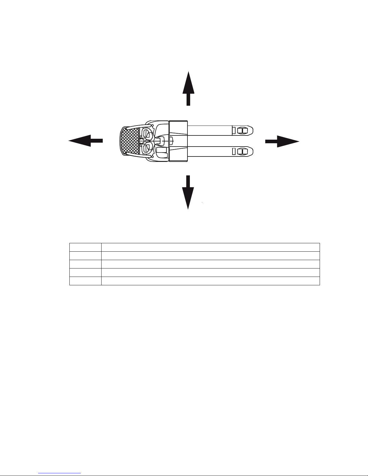
2 Travel direction definition
The following determinations have been made for travel direction specification:
Item Travel direction
1 Left
2 Drive direction
3 Load direction
4 Right
1
2 3
4
Page 18
17
02.15 EN
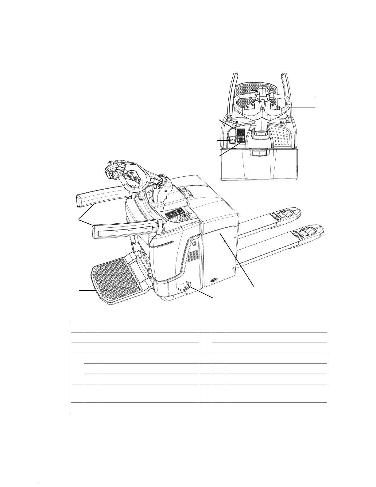
3 Assemblies and Functional Description
3.1 Assembly Overview
Item Component Item Component
5 t Travel switch 9 o CanDis
6 t Tiller t Charge indicator
7 t Key switch 10 t Folding operator platform
o CanCode 11 o Folding side restraint
o ISM 12 o Mains cable (on-board charger)
8 t Emergency Disconnect (main
switch)
13 t
Support wheel
t = Standard version o = Option
10
10
5
6
8
9
13
7
11
12
Page 19

02.15 EN
18
3.2 Functional Description
Safety Mechanisms
An enclosed, smooth truck perimter with rounded edges ensures safe handling of the
truck. The wheels are surrounded by a solid skirt.
When released a gas pressure spring pushes the tiller up and activates braking.
If the truck touches a person, the red collision safety switch changes the travel
direction in pedestrian mode when travelling in drive direction with the platform and
the side restraints folded up (o). The truck brakes, travels away from the operator
and stops. This prevents the operator from being hit.
The collision safety feature can also be activated for rider mode (o).
Activating the Emergency Disconnect switch rapidly cuts out all electrical functions in
hazardous situations.
The protective mesh (o) protects the operator from sliding loads.
Emergency Stop safety feature
The Emergency Stop is activated by the traction controller. Each time the truck is
switched on the system performed a self diagnosis. If an error is detected, the truck
automatically brakes to a halt. Control displays in the CanDis display instrument (o)
indicate the Emergency Stop.
CAUTION!
The truck brakes automatically
If the truck detects that signals which are required have not been received, or if it
detects an error, the system reacts by triggering an emergency stop, either by braking
the truck to a halt or until a valid signal status has been reached.
XIn rider mode: Take up a stable standing position and hold on with both hands.
XIn pedestrian mode: Remain at a suitable distance from the truck during operation.
Hydraulic system
Pressing the lifting button starts the pump unit, supplying hydraulic oil from the oil
reservoir to the lift cylinder. Pressing the lifting button raises the load handler at a
constant speed; pressing the lowering button lowers the load handler.
Ergonomic lift (
o
) (ERE C20)
For lifting and lowering, the truck is equipped with support arm lift (initial lift) with the
maximum lift capacity and mast lift (high lift) with a lower lift capacity.
Drive system
A fixed AC three-phase motor actuates the drive wheel via a bevel spur gearbox. The
electronic traction controller ensures smooth drive-motor-speed control and hence
smooth starting, powerful acceleration and electrically controlled braking with energy
regeneration. The driver can choose from 3 travel programs depending on the load
and the environment: from high-performance to energy-saving.
o
Page 20

19
02.15 EN
Tiller
The driver steers with an ergonomic tiller. All travel and lift operations can be
performed sensitively without having to reach. The tiller has a steer angle of 180°.
Electrical system
The truck has an electronic traction controller. The operating voltage of the truck's
electrical system is 24 volts.
Controls and displays
Ergonomic controls ensure fatigue-free operation for sensitive application of the
travel and hydraulic operations. The battery discharge indicator shows the available
battery capacity. The CanDis display (o) shows information which is important for the
operator such as travel program, service hours, battery capacity and event
messages.
3.2.1 Hourmeter
Z Prepare the truck for operation, see "Preparing the truck for operation" on page 62
or see "CanCode Keypad (o)" on page 95.
Service hours are counted while the truck is operational and one of the following
controls is applied:
– Tiller in travel zone "F", see "Travel" on page 72.
– "Lift" button, see page 80.
– "Lower" button, see page 80.
Page 21

02.15 EN
20
4 Technical Specifications
Z The technical specifications comply with the German "Industrial Truck Data Sheet"
Guidelines.
Technical modifications and additions reserved.
4.1 Performance data
1)
2000 kg only with support arm lift h5 = 122 mm.
In mast lift h3 reduced capacity 700 kg.
Description ERE 120 ERE C20
Q Rated capacity 2000 kg
Q Rated capacity (support arm lift / mast lift)
1)
2000 / 700 kg
D Load centre distance with standard fork length 600 600 mm
Travel speed, pedestrian mode with/without rated
load
4.2 4.2 km/h
Travel speed, rider mode with/without rated load 7.5 / 8.5 6.0 / 6.0 km/h
Lift time with/without rated load 3.3 / 2.9 s
Lift time, support arm lift with/without rated load 3.6 / 2.7 s
Lift time, mast lift with/without rated load 3.4 / 2.0 s
Lift speed with/without rated load 0.4 / 0.4 0.16 / 0.27 m/s
Lowering time with/without rated load 1.5 / 2.0 s
Lowering time, support arm lift with/without rated
load
6.0 / 8.6 s
Lowering time, mast lift with/without rated load 3.1 / 3.6 s
Lowering speed with/without rated load 0.06 / 0.06 0.17 / 0.15 m/s
Max. gradeability (5 min) with/without rated load 8 / 16 8 / 16 %
Drive motor S2 60 min 1.6 1.6 kW
Lift motor S3 10% 2.2 2.2 kW
Page 22
21
02.15 EN
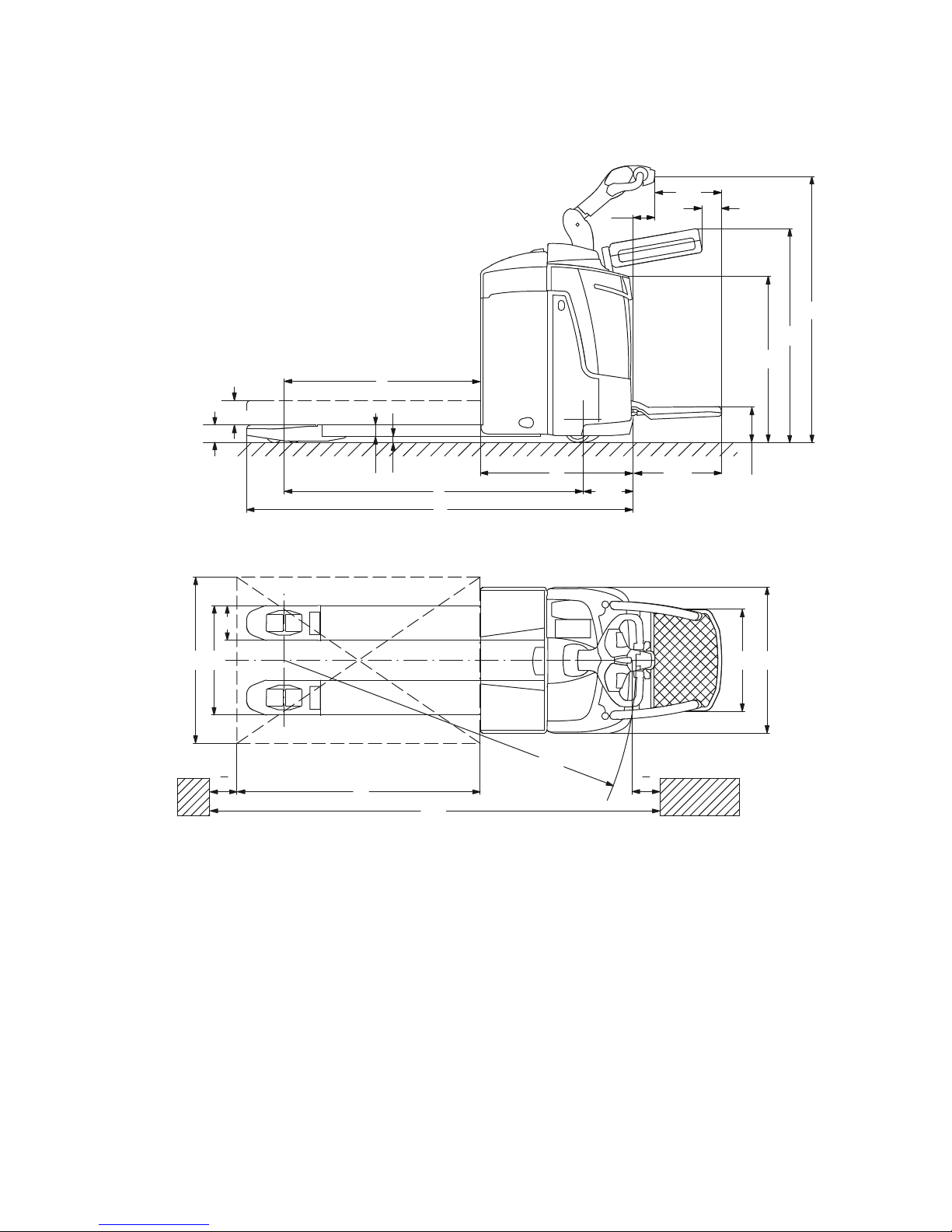
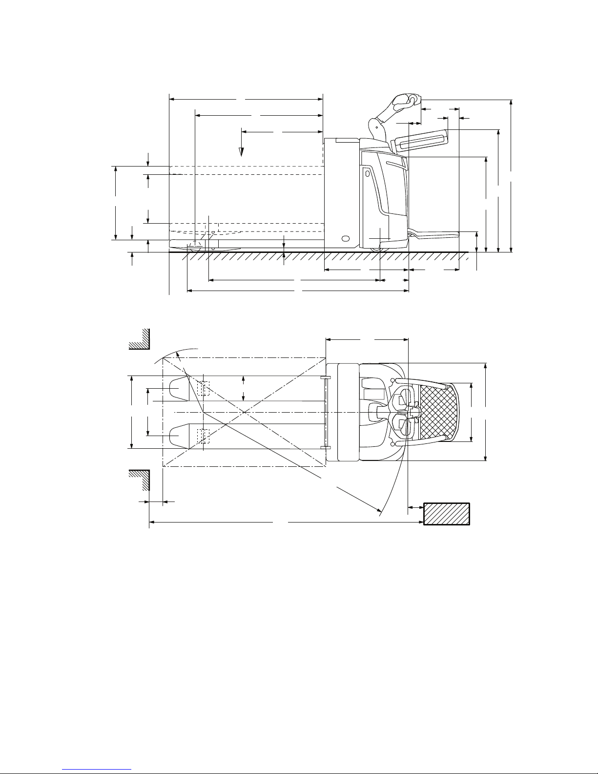
4.2 Dimensions
ERE 120
Wa
98
h
14
1053
820
224
330
107
436
l
2
x
h
3
h
13
l
1
s
m
2
248
y
b
12b5
e
l
6
Ast
a
2
a
2
b
1
500
Page 23
02.15 EN
22
ERE C20
l
2
h5
h13
h14
98
330
107
1053
820
22 4
500
24 8
436
h3
l1
y
m2
l
D
x
Q
s
b11
Wa
a
2
a
2
Ast
e
R
b5
b1
l2
Page 24

23
02.15 EN
1 Load section raised and platform folded in if load section lowered +55 mm
2 Diagonal in accordance with VDI +205 mm
3 Diagonal in accordance with VDI +369 mm
4 Dimensions with top battery removal / with side battery removal +72 mm
Description ERE 120
h14 Tiller height in travel position 1146/1428 mm
h13 Lowered fork height 85 mm
h3 Rated lift 122 mm
b1/b2 Overall width 720 mm
b5 Width across forks 510/540/670 mm
b10 Track width, front 338/368/498 mm
b11 Track width, rear 500 mm
s/e/l Fork dimensions 55/172/1150 mm
a Safety clearance 200 mm
l1
4)
Overall length (M/L) 1834/1906 mm
l2
4)
Headlength (M/L) 682/754 mm
m2 Ground clearance, centre of wheelbase 30 mm
Ast
1)3)4)
Aisle width for pallets 1000 x 1200
crossways (M/L)
2032/2104 mm
Ast
1)2)4)
Aisle width for pallets 800 x 1200
lengthways (M/L)
2082/2154 mm
Wa1) Turning radius (M/L) 1595/1667 mm
Net weight: See truck data plate
Page 25

02.15 EN
24
1 Load section raised and platform folded in if load section lowered +53 mm
2 Diagonal in accordance with VDI +205 mm
3 Diagonal in accordance with VDI +369 mm
4 Dimensions with battery removal from above
Description ERE C20
h14 Tiller height in travel position 1146/1428 mm
h13 Lowered fork height 90 mm
h3 Mast lift 540 mm
h5 Support arm lift 122 mm
b1/b2 Overall width 720 mm
b5 Width across forks 540 mm
b10 Track width, front 508 mm
b11 Track width, rear 500 mm
s/e/l Fork dimensions 60/187/1150 mm
a Safety clearance 200 mm
l1
4)
Overall length 1850 mm
l2
4)
Length to fork face 700 mm
m2 Ground clearance, centre of wheelbase 30 mm
Ast
1)3)4)
Aisle width for pallets 1000x1200
crossways
2114 mm
Ast
1)2)4)
Aisle width for pallets 800 x 1200
lengthways
2164 mm
Wa1) Turning radius 1614/1667 mm
Net weight: See truck data plate
Page 26

25
02.15 EN
Aisle widths
ERE 120 / ERE C20
(all dimensions in mm)
1) Load section raised; if load section lowered +55 mm
2) In rider mode: +436 mm
3) Battery compartment L version / for battery compartment M version: -72 mm
4) Battery removal from the top; with battery removal from the side additional: +72
mm
A
st=Wa+l6
-x+a (pallet length)
ll
1
3)4)
y
1)3)4)
x
1)
l
6
b
12
W
a
1)2)3)
4)
A
st
2)3)4)
Battery compartment L - Headlength l2 = 754 mm
3)
1000 186 1756 1269 763 1000 800 1517 1954
1150 186 1906 1419 913 1200 800 1667 2154
1200 186 1956 1469 963 1200 800 1717 2154
1400 186 2156 1669 1163 1400 700 1917 2354
1600 186 2356 1869 1363 1600 1200 2117 2554
1750 558 2506 1647 1141 1800 1000 1895 2754
1800 558 2556 1697 1191 1800 1000 1945 2754
1950 558 2706 1847 1341 2000 800 2095 2954
2150 558 2906 2047 1541 2100 700 2295 3054
2400 558 3156 2297 1791 2400 1200 2545 3354
2400 800 3156 2055 1549 2400 1200 2303 3354
l Fork length
l
1
Overall length
y Wheelbase
x Load distance
l
6
Load length
b
12
Load width
W
a
Turning radius
A
st
Working aisle width
requirements
Page 27

02.15 EN
26
4.3 Weights
Z Weights and axle loads vary depending on truck features.
Z Weights and axle loads vary depending on truck features.
4.4 Tyre type
Description ERE 120
Net weight excl. battery (M/L) 440/443 kg
Axle loading, laden
front/rear + battery (L)
1702/1043 kg
Axle loading, unladen
front/rear + battery (L)
155/590 kg
Description ERE C20
Net weight excl. battery 503 kg
Axle loading, laden
front/rear + battery
1258/1399 kg
Axle loading, unladen
front/rear + battery
128/525 kg
Description ERE 120
Tyre size, front 230 x 65 mm
Tyre size, rear (single / tandem) 85 x 110 / 85 x 85 mm
Support wheel (twin roller) 125 x 54 mm
Wheels, number front / rear
(x = driven)
2 or 4 / 1x + 2
Description ERE C20
Tyre size, front 230 x 65 mm
Tyre size, rear (single / tandem) 82 x 70 / 82 x 100 mm
Support wheel (twin roller) 125 x 54 mm
Wheels, number front / rear
(x = driven)
2 or 4 / 1x + 2
Page 28

27
02.15 EN
4.5 EN norms
Continuous sound pressure level
– ERE 120 / ERE C20: 73 dB(A)
in accordance with EN 12053 as harmonised with ISO 4871.
Z The continuous sound pressure level is calculated according to standard
procedures and takes into account the sound pressure level when driving, lifting
and idling. The sound pressure level is measured at the driver’s ear.
Z Noise levels can fluctuate depending on the floor composition and wheel lining.
Vibration
– ERE 120 / ERE C20: 0,94 m/s²
in accordance with EN 13059
Z The vibration acceleration acting on the body in its operating position is the linearly
integrated, weighted acceleration in the vertical axis according to the standard. It is
calculated when travelling over thresholds at constant speed. These recordings
were taken on a single occasion and must not be confused with the human
vibrations of the "2002/44/EC/Vibrations" operator directive. The manufacturer
offers a special service to measure these human vibrations, see "Human vibration
measurement" on page 148.
Electromagnetic compatibility (EMC)
The manufacturer confirms that the truck adheres to the limits for electromagnetic
emissions and resistance as well as the static electricity discharge test in accordance
with EN 12895 as well as the standardised instructions contained therein.
Z No changes to electric or electronic components or their arrangement may be
made without the written agreement of the manufacturer.
WARNING!
Medical equipment can be damaged by non-ionised radiation
Electrical equipment on the truck emitting non-ionised radiation (e.g. wireless data
transmission) can affect operators' medical equipment (pacemakers, hearing aids
etc.) and result in malfunctions. Consult a doctor or the manufacturer of the medical
equipment to clarify whether it can be used near the industrial truck.
Page 29

02.15 EN
28
4.6 Conditions of use
Ambient temperature
– without cold store equipment: operating at -10°C to 40°C, see "Internal Operation
Combined with Brief External or Cold Store Operation (t)" on page 13
– with cold store equipment: operating at -28°C to +25°C, see "Internal Operation in
Cold Stores with Cold Store Equipment (o)" on page 13
Z Special equipment and authorisation are required if the truck is to be used
continually in conditions of extreme temperature or condensing air humidity
fluctuations.
4.7 Electrical Requirements
The manufacturer certifies compliance with the requirements for the design and
manufacture of electrical equipment, according to EN 1175 "Industrial Truck Safety Electrical Requirements", provided the truck is used according to its purpose.
Page 30
29
02.15 EN
5 Identification Points and Data Plates
Z Warnings and notices such as capacity charts, strap points and data plates must
be legible at all times. Replace if necessary.
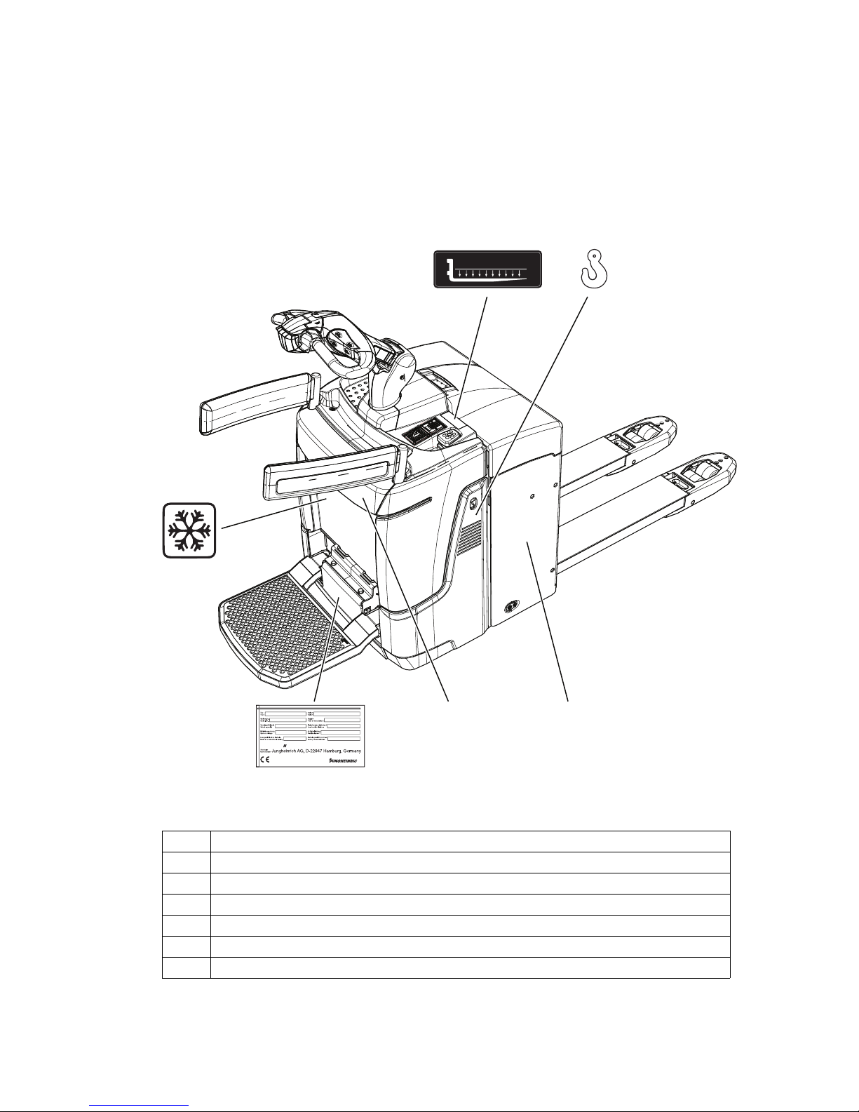
5.1 Indication Points
ERE 120
Item Component
14 Capacity Qmax
15 Attachment points for lifting by crane
16 Cold store (o)
17 Model name
18 Battery data plate
19 Data plate
Q
max
XXX
kg
19
14 15
16
1817
Page 31

02.15 EN
30
ERE C20
Item Component
14 Capacity Qmax
15 Attachment points for lifting by crane
17 Model name
18 Battery data plate
19 Data plate
20 Serial number (etched into the truck chassis)
21 Ergonomic lift capacity plate
Q
max
XXX
kg
kg
kg
Q max
Q max
600
Dmm
Hmm
2000
700
750
210
19
14 15
21
1817
20
Page 32

31
02.15 EN
5.2 Data plate
Z The illustration shows the standard version for EU member states. The data plate
may differ in other countries.
Z For queries regarding the truck or ordering spare parts always quote the truck serial
number (23).
22 23 2524 26
33
29
32
31
30
2827
Item Description Item Description
22 Type 28 Year of manufacture
23 Serial number 29 Load centre (mm)
24 Rated capacity (kg) 30 Output
25 Battery voltage (V) 31 Min./max. battery weight (kg)
26 Net weight w.o. battery (kg) 32 Manufacturer
27 Option 33 Manufacturer’s logo
Page 33

02.15 EN
32
5.3 Truck capacity plate
The capacity plate (14) gives the maximum load-bearing capacity (Q) of the truck in
kg assuming the load on the load handler is evenly distributed.
Capacity plate, ergonomic lift(
o
) (ERE C20)
5.4 Wind loads
Wind forces can affect the stability of a truck when lifting, lowering and transporting
loads with large surface areas.
Light loads must be especially secured when they are subjected to wind forces. This
will prevent the load from sliding or falling.
Stop the truck in both cases.
A = Travelling with a raised load prohibited
B = Max. capacity for horizontal transporting with raised support arms without
mast lift: 2000 kg
C = High-level lift height: 210 - 750 mm
Max. high-level lift capacity: 700 kg
Q
max
XXX
kg
14
kg
kg
Q max
Q max
600
Dmm
Hmm
2000
700
750
210
A
B
C
21
o
Page 34

33
02.15 EN
C Transport and Commissioning
1 Lifting by crane
WARNING!
All persons involved in loading by crane must be trained
Incorrect crane loading procedures due to untrained personnel can cause the truck
to fall. There is a risk of injury to personnel and a risk of material damage to the truck.
XLoading must only be performed by specialist personnel trained for this purpose.
The specialist personnel must be instructed in securing loads on road vehicles and
handling load securing devices. In each case correct measurements must be taken
and appropriate safety measures applied.
WARNING!
Incorrect lifting by crane can result in accidents
Improper use or use of unsuitable lifting gear and can cause the truck to fall when
being lifted by crane.
Prevent the truck from hitting other objects during lifting, and avoid uncontrolled
movements. If necessary, secure the truck with guide ropes.
XThe truck should only be loaded by personnel trained in the use of lifting slings and
tools.
XWear personal protective equipment (e. g. safety shoes, safety helmet, hi-vis
jacket, protective gloves, etc.) when loading by crane.
XDo not stand under suspended loads.
XDo not enter or stand in a hazardous area.
XAlways use lifting gear with sufficient capacity (for truck weight see truck rating
plate).
XAlways attach the crane lifting gear to the prescribed strap points and prevent them
from slipping.
XUse the lifting slings only in the prescribed loading direction.
XCrane slings should be fastened in such a way that they do not come into contact
with any attachments when lifting.
Lifting the truck by crane
Requirements
– Park the truck securely, see "Parking
the truck securely" on page 65.
Tools and Material Required
– Lifting gear
– Crane lifting gear
Procedure
• Secure the lifting slings to the strap
points (15).
15
15
15
15
Page 35

02.15 EN
34
The truck can now be lifted by crane.
Page 36

35
02.15 EN
2 Remove the transport lock
The transport lock ensures that the truck is braked during transport without the mass
of the battery.
Z There is an instruction decal by the front cover for the transport lock (35). This must
be removed once the battery has been installed.
Remove the transport retainer
Requirements
– Fold down the operator platform.
– Remove the front panel, see "Front cover disassembly" on page 137.
Procedure
• Remove the cable binder latch (34).
• Undo the nut (36) and remove the transport retainer.
The transport retainer is removed and the industrial truck can be started as specified,
see "Starting up the truck" on page 61.
Z Leave the transport retainer on the truck for later transportation without a battery.
36
34
35
Page 37

02.15 EN
36
3 Transport
WARNING!
Uncontrolled movement during transport
Improper fastening of the truck and mast during transport can result in serious
accidents.
XLoading is only to be carried out by specially trained staff. The specialist personnel
must be instructed in the securing of loads on road vehicles and in the use of load-
securing equipment. When securing the truck, the appropriate measures must be
determined and applied for each individual case.
XThe truck must be securely fastened when transported on a lorry or a trailer.
XThe lorry or trailer must have lashing rings.
XUse wedges to prevent the truck from moving.
XUse only lashing straps with sufficient load rating.
XUse anti-slip material to secure loading aids (pallets, wedges,...), e. g. anti-slip
mats.
Securing the industrial truck for
transport
Requirements
– Load the truck.
– Park the truck securely, see "Parking the
truck securely" on page 65.
Tools and Material Required
– Lashing straps
Procedure
• Attach the lashing straps (37) to the
industrial truck and the transport vehicle
and tension sufficiently.
The truck can now be transported.
37
Page 38

37
02.15 EN
4 Using the Truck for the First Time
WARNING!
The use of unsuitable energy sources can be hazardous
Rectified AC current will damage the assemblies (controllers, sensors, motors etc.)
of the electronic system.
Unsuitable cable connections (too long, insufficient wire cross-section) to the battery
(tow cables) can overheat, setting the truck and battery on fire.
XThe truck must only be operated with battery current.
XCable connections to the battery (tow leads) must be less than 6 m long and have
a minimum cross-section of 50 mm².
Procedure
• Check the equipment is complete.
• If necessary, install the battery, see "Battery removal and installation" on page 51.
• Charge the battery, see "Charging the battery" on page 44.
The truck can now be started, see "Starting up the truck" on page 61.
NOTE
Do not lift loads if the truck is operated via a tow lead with an external battery.
NOTE
Cold store trucks
XTrucks designed for use in cold stores have a cold store hydraulic oil.
XIf a truck with cold store oil is used outside the cold store, the lowering speeds may
increase.
Wheel flattening
If the truck has been parked for a long period, the wheel surfaces may tend to flatten.
This flattening has a negative effect on the safety and stability of the truck. Once the
truck has covered a certain distance, the flattening will disappear.
Page 39

02.15 EN
38
Page 40

39
02.15 EN
D Battery - Servicing, Recharging,
Replacement
1 Safety Regulations Governing the Handling of Lead-Acid
Batteries
Maintenance personnel
Batteries may only be charged, serviced or replaced by trained personnel. These
operating instructions and the manufacturer’s instructions concerning batteries and
charging stations must be observed when carrying out the work.
Fire Protection
Do not smoke and avoid naked flames when handling batteries. Wherever an
industrial truck is parked for charging there must be no inflammable material or
consumables capable of creating sparks within a minimum distance of 2 m from the
truck. The room must be ventilated. Fire protection equipment must be available.
CAUTION!
The use of unsuitable fire protection equipment can result in scalding
Extinguishing fires with water can cause a reaction with the battery acid. This can
result in scalding from the acid.
XUse powder extinguishers.
XNever extinguish a burning battery with water.
Battery maintenance
The battery cell covers must be kept dry and clean. The terminals and cable shoes
must be clean, secure and have a light coating of dielectric grease.
CAUTION!
Short circuits can cause fires
Damaged cables can cause a short circuit, setting the truck and the battery on fire.
XBefore closing the battery cover make sure that the battery cables cannot be
damaged.
Battery disposal
Batteries may only be disposed of in accordance with national environmental
protection regulations or disposal laws. The manufacturer’s disposal instructions
must be observed.
Page 41

02.15 EN
40
WARNING!
Batteries can be hazardous
Batteries contain an acid solution which is poisonous and corrosive. Avoid contact
with battery acid at all times.
XDispose of used battery acid in accordance with regulations.
XAlways wear protective clothing and goggles when working with batteries.
XDo not let battery acid come into contact with skin, clothing or eyes. If necessary,
rinse with plenty of clean water.
XIn the event of physical damage (e.g. skin or eye contact with battery acid) call for
a doctor immediately.
XSpilled battery acid should be neutralised immediately with plenty of water.
XOnly batteries with a sealed battery container may be used.
XFollow national guidelines and legislation.
WARNING!
Unsuitable batteries that have not been approved by Jungheinrich for the truck
can be hazardous
The design, weight and dimensions of the battery have a considerable effect on the
operational safety of the truck, in particular its stability and capacity. The use of
unsuitable batteries that have not been approved for the truck by Jungheinrich, can
lead to a deterioration of the braking characteristics of the truck during energy
recovery, causing considerable damage to the electric controller and resulting in
serious danger to the health and safety of individuals.
XOnly Jungheinrich-approved batteries may be used on the truck.
XBattery equipment may only be replaced with the agreement of Jungheinrich.
XWhen replacing/installing the battery make sure the battery is securely located in
the battery compartment of the truck.
XDo not use batteries that have not been approved by the manufacturer.
Park the truck securely before carrying out any work on the batteries (see "Parking
the truck securely" on page 65).
Page 42

41
02.15 EN
2 Battery types
Depending on the model, the truck will be supplied with different battery types. The
following table shows which combinations are included as standard:
The battery weights can be taken from the battery data plate. Batteries with non
insulated terminals must be covered with a non slip insulating mat.
ERE 120 Battery tray M
ERE 120 Battery tray L
Battery type Capacity (Ah) Min. weight
(kg)
Max. dimensions
(mm)
24 volt battery 2PzV 200 204 624X212X628
24 volt battery 2PzW 230 204 624X212X628
24 volt battery 2PzS 250 204 624X212X628
24 volt battery 2PzS 250 Lib.Silver 204 624X212X628
24 volt battery 2PzM 250 204 624X212X628
24 volt battery 2PzV 220 Hawk 204 624X212X628
24 volt battery XFC 158 204 624X212X628
Battery type Capacity (Ah) Min. weight
(kg)
Max. dimensions
(mm)
24 volt battery 3PzV 300 273 624X284X628
24 volt battery 3PzW 330 273 624X284X628
24 volt battery 3PzS 375 273 624X284X628
24 volt battery 3PzS 345 Lib.Silver 273 624X284X628
24 volt battery 3PzS 375 Lib.Silver 273 624X284X628
24 volt battery 3PzM 375 273 624X284X628
24 volt battery 3PzV 330 Hawk 273 624X284X628
24 volt battery XFC 316 273 624X284X628
Page 43

02.15 EN
42
ERE C20 Battery tray S
Battery type Capacity (Ah) Min. weight
(kg)
Max. dimensions
(mm)
24 volt battery 2PzB 200 166 662X147X686
24 volt battery 2PzVB 170 176 657X147X686
24 volt battery 2PzVB 142 133 652X147X560
24 volt battery 2PzB 150 144 662 x 147 x 592
24 volt battery 2PzB 150 Lib.Silver 144 662 x 147 x 592
24 volt battery 2PzB 200 Lib.Silver 176 657X147X686
24 volt battery 2PzMB 140 144 662 x 147 x 592
24 volt battery 2PzVB 162 Hawk 166 662X147X686
24 volt battery 2PzVB 134 Hawk 144 662 x 147 x 592
24 volt battery XFC 158 144 662 x 147 x 592
24 volt battery XFC 177 166 662X147X686
Page 44

43
02.15 EN
3 Exposing the battery
WARNING!
An unsecured truck can cause accidents
Parking the truck on an incline or with a raised load handler is dangerous and is
strictly prohibited.
XPark the truck on a level surface. In special cases the truck may need to be secured
with wedges.
XFully lower the load handler.
XSelect a place to park where no other people are at risk of injury from the lowered
load handler.
XIf the brakes are not working, place wedges underneath the wheels of the truck to
prevent it from moving.
CAUTION!
A closing battery panel can pose a trapping hazard
If the battery cover is not opened fully, it can suddenly close on its own and cause
bruising. The battery cover is only properly opened at an angle greater than 90°. It is
then held by gravity.
XOpen the battery cover as far as the stop.
Requirements
– Park the truck on a level surface.
– Park the truck securely, see "Parking the
truck securely" on page 65.
Procedure
• Depress the Emergency Disconnect (8).
• Pull up the battery panel (39) using the
recess and lift it back (38).
The battery connector and battery retainer
can be accessed
39
38
8
Page 45

02.15 EN
44
4 Charging the battery
WARNING!
The gases produced during charging can cause explosions
The battery gives off a mixture of oxygen and hydrogen (electrolytic gas) during
charging. Gassing is a chemical process. This gas mixture is highly explosive and
must not be ignited.
XSwitch the charging station and truck off first before connecting/disconnecting the
charging cable of the battery charging station to/from the battery connector.
XThe charger must match the battery in terms of voltage, charge capacity and
battery type.
XBefore charging, check all cables and plug connections for visible signs of damage.
XVentilate the room in which the truck is being charged.
XThe battery cover must be open and the battery cell surfaces must be exposed
during charging to ensure adequate ventilation.
XDo not smoke and avoid naked flames when handling batteries.
XWherever an industrial truck is parked for charging there must be no inflammable
material or consumables capable of creating sparks within a minimum distance of
2 m from the truck.
XFire-control equipment must be available.
XDo not place any metallic objects on the battery.
XAlways follow the safety regulations of the battery and charger station
manufacturers.
NOTE
Battery damage
The battery, charger (charge characteristics) and battery parameters must match
each other, otherwise damage may result.
Page 46

45
02.15 EN
4.1 Charging the battery with a stationary charger
Charging the battery
Requirements
– Expose the battery, see "Exposing
the battery" on page 43.
Procedure
• Disconnect the battery
connector (40) from the truck
connector.
• Connect the battery connector (40) to
the charging cable (41) of the
stationary charger.
• Start charging in accordance with the charger operating instructions.
The battery is charging.
Completing battery charging, restoring the truck to operation
NOTE
If charging has been interrupted, the full battery capacity will not be available.
Requirements
– The battery is fully charged.
Procedure
• Complete charging in accordance with the charger operating instructions.
• Disconnect the battery connector (40) from the charging cable (41) of the stationary
charger.
• Attach the battery connector (40) to the industrial truck.
The truck is now ready for operation.
40
41
Page 47

02.15 EN
46
4.2 Charging the battery with an on-board charger (o)
DANGER!
Risk of electric shock and fire
Damaged and unsuitable cables can cause electric shocks and can overheat,
resulting in fires.
XAlways use mains cables with a maximum length of 30 m.
Local regulations must be observed.
XUnwind the cable reel fully when using it.
XAlways use original manufacturer’s mains cables.
XInsulation safety, acid and caustic ratings must comply with the manufacturer's
mains lead.
XThe charging connector must be dry and clean when used.
NOTE
Improper use of the on-board charger can cause material damage
The on-board charger consisting of a battery charger and battery controller must not
be opened. If faulty, contact the manufacturer’s customer service department.
XThe charger must only be used for batteries supplied by Jungheinrich or other
approved batteries provided it has been adapted by the manufacturer's customer
service department.
XBatteries must never be swapped from truck to truck.
XDo not connect the battery to two chargers simultaneously.
4.2.1 Setting the charging characteristics (ELH 2415 / 2425 / 2435)
The charging characteristics (ELH 2415 / 2425 / 2435) are set via parameter 1388 of
the truck software, see "Set ELH 2415 / 2425 / 2435 Charger Characteristics with
CanCode" on page 123.
The CanCode and CanDis option is necessary to set the charging characteristics.
Otherwise, the setting may only be performed by the manufacturer's customer
service department.
Flashing sequence / charging curve assignment (ELH 2415/2425/2435)
Flashing sequence Selected charging curves (characteristics)
0 Truck without battery
o
Page 48

47
02.15 EN
NOTE
XIf parameter 1388 is incorrectly set the charger will be inhibited and the battery will
not charge.
XWith PzS 200-300 Ah wet cell batteries both characteristic curves 1 and 2 can be
used.
XIf a characteristic is set on ELH 2415 / 2425 that is not supported by the charger,
the charge display is lit a steady red.
XAll other characteristics ( 8) block the charger, and the battery is not charged.
1
Wet cell battery: PzS with 100 - 300 Ah
Wet cell battery: PzM with 100 - 179 Ah
2
Wet cell battery: PzS with pulse characteristic 200 400 Ah
Wet cell battery: PzM with pulse characteristic 180 400 Ah
3 Maintenance-free: PzV with 100 - 150 Ah
4 Maintenance-free: PzV with 151 - 200 Ah
5
Wet cell battery: PzS with pulse characteristic 201 300 Ah
6 Maintenance-free: PzV 301 - 330 Ah
7 Cold store
Flashing sequence / charging curve assignment (ELH 2415/2425/2435)
Flashing sequence Selected charging curves (characteristics)
Page 49

02.15 EN
48
4.2.2 Charging the battery
Starting to charge with the on-board charger
– ELH mains connection
Mains supply: 230 V / 115 V (+15/-10%)
Mains frequency: 50 Hz / 60 Hz
The mains connector of the charger (42) is integrated in the battery compartment (the
illustration shows the battery compartment of the ERE 120).
Charging the battery
Requirements
– Park the truck securely, see "Parking the truck securely" on page 65.
– Expose the battery, see "Exposing the battery" on page 43.
– Correct charging program set on charger.
Procedure
• Remove any insulating mats from the battery.
• The battery connector must remain plugged.
• Attach the mains connector to a mains socket.
• Pull the Emergency Disconnect switch up.
The flashing LED indicates the charge status or a fault (for flashing codes see “LED
Display” table).
The battery is now charged.
Z When the mains connector is attached to the mains all the truck’s electrical
functions are disconnected (electric immobiliser). The truck cannot be operated.
Z When the mains connector is attached to the mains the battery connector cannot
be disconnected.
42
Page 50

49
02.15 EN
Completing the battery charge, restoring the truck to operation
NOTE
If charging has been interrupted, the full battery capacity will not be available
Requirements
– Battery charging is complete.
Procedure
• Remove the mains connector from the socket and store it in the battery
compartment with the cable.
• If applicable, place the existing insulating mats back over the battery.
• Close the battery panel securely.
The truck is now ready for operation.
CAUTION!
Damaged mains cables can be hazardous
XDo not trap the mains cable when closing the battery panel.
Charging times
The duration of charge depends on the battery capacity.
Z Charging continues automatically after a mains failure. Charging can be interrupted
by removing the mains connector and continued as partial charging.
Page 51

02.15 EN
50
LED display (43)
Compensation charge
The compensation charge starts automatically when charging is complete.
Partial charging
The charger is designed to automatically adapt to partially charged batteries. This
keeps battery wear to a minimum.
Green LED (charge status)
Lit Charging complete, battery full.
(Charge interval, float or
compensation charge).
Slow flash Charging.
Rapid flash Display at beginning of charge or
after setting a new characteristic
curve. Number of flash pulses
corresponds to the characteristic
curve set.
Red LED (fault)
Lit Charging characteristics or battery parameters
invalid
Slow flash 1xflash with noticeable interval: Overvoltage
detected before charging starts
2xflash with noticeable interval: Max. charge time
exceeded
3xflash with noticeable interval: Max. charge
capacity exceeded
4xflash with noticeable interval: Control deviation
lmax
5xflash with noticeable interval: Overvoltage cutout
6xflash with noticeable interval: Low voltage cutout
7xflash with noticeable interval: Battery is faulty,
battery error
8xflash with noticeable interval: Fan error
9xflash with noticeable interval: Battery
disconnected from charger during charging.
10xflash with noticeable interval: Equipment
overtemperature
43
Page 52

51
02.15 EN
5 Battery removal and installation
WARNING!
Accident risk during battery removal and installation
Due to the battery weight and acid there is a risk of trapping or scalding when the
battery is removed and installed.
XNote the "Safety regulations for handling acid batteries" section in this chapter.
XWear safety shoes when removing and installing the battery.
XUse only batteries with insulated cells and terminal connectors.
XPark the truck on a level surface to prevent the battery from sliding out.
XMake sure the crane slings have sufficient capacity to replace the battery.
XUse only approved battery replacement devices (battery roller stand, replacement
trolley etc.).
XMake sure the battery is securely located in the truck's battery compartment.
CAUTION!
Trapping hazard
There is a risk of trapping when you close the battery cover.
XMake sure there is nothing between the battery cover and the truck when you close
the battery cover.
Page 53

02.15 EN
52
5.1 Removing the battery from the top
Battery removal
Requirements
– Park the truck securely, see "Parking the truck securely" on page 65.
– Expose the battery, see "Exposing the battery" on page 43.
Procedure
• Remove the battery panel on trucks with a protective grille (o).
• Disconnect the battery connector from the truck connector.
Z Place the battery cable on the tray so that it cannot be severed when the battery is
pulled out.
• Undo the screw (45) of the battery retainer and remove the battery retainer (44).
• Attach the crane lifting gear to the eyes (46).
Z The crane lifting gear must exert a vertical pull. The hooks of the lifting gear must
never fall onto the battery cells.
• Pull the battery up out of the battery compartment.
The battery has now been removed.
Z Assembly is in the reverse order. Note the correct mounting position and make sure
the battery is connected correctly.
45 44
46
Page 54

53
02.15 EN
5.2 Removing the battery from the side
CAUTION!
Trapping hazard
Trapping hazard when removing and installing the battery.
XWhen removing and installing the battery do not put your hands between the
battery and the chassis.
Battery removal
Requirements
– Park the truck securely, see "Parking the truck
securely" on page 65.
– Expose the battery, see "Exposing the battery"
on page 43.
Tools and Material Required
– Battery replacement station / trolley
Procedure
• Disconnect the battery connector (40) from the
truck connector.
• Undo the battery lock (47).
• Move the battery replacement station / trolley up
to the side of the truck.
• Turn the battery lock as far as the stop.
• Carefully push the battery from off the truck onto the battery replacement station /
trolley.
The battery is now removed.
Battery installation
Requirements
– Park the truck securely, see "Parking the truck
securely" on page 65.
– Expose the battery, see "Exposing the battery"
on page 43.
Procedure
Z Installation is in the reverse order. When
reinstalling the battery, note the proper
installation position and make sure the battery is
connected correctly.
47
47
Page 55

02.15 EN
54
Page 56

55
02.15 EN
E Operation
1 Safety Regulations for the Operation of the
Forklift Truck
Driver authorisation
The truck may only be used by suitably trained personnel, who have demonstrated to
the proprietor or his representative that they can drive and handle loads and have
been authorised to operate the truck by the proprietor or his representative.
Operator’s rights, responsibilities and rules of conduct
The driver must be informed of his duties and responsibilities and be instructed in the
operation of the truck and shall be familiar with the operating instructions. Safety
shoes must be worn on pedestrian-operated trucks.
Unauthorised use of truck
The operator is responsible for the truck during the time it is in use. The operator must
prevent unauthorised persons from driving or operating the truck. Do not carry
passengers or lift other people.
Damage and faults
The supervisor must be informed immediately of any damage or faults to the truck or
attachment. Trucks which are unsafe for operation (e.g. wheel or brake problems)
must not be used until they have been rectified.
Repairs
The operator must not carry out any repairs or alterations to the truck without
authorisation and the necessary training to do so. The operator must never disable or
adjust safety mechanisms or switches.
Page 57

02.15 EN
56
Hazardous area
WARNING!
Risk of accidents/injury in the hazardous area of the truck
A hazardous area is defined as the area in which people are at risk due to travel or
lifting operations of the truck, its load handler or the load. This also includes the area
within reach of falling loads or lowering/falling operating equipment.
XInstruct unauthorised persons to leave the hazardous area.
XIn case of danger to third parties, give a warning signal in good time.
XIf unauthorised persons are still within the hazardous area, stop the truck
immediately.
Safety devices, warning signs and warning instructions
Safety devices, warning signs (see "Identification Points and Data Plates" on
page 29) and warning instructions in the present operating instructions must be
strictly observed.
WARNING!
Removing or disabling safety devices can cause accidents
Removing or disabling safety devices such as the emergency disconnect switch, key
switch, buttons, horn, strobe lights, sensors, panels, etc. can result in accidents and
injury.
XReport any defects immediately to your supervisor.
XMark defective truck and take it out of service.
XDo not return the truck to service until you have identified and rectified the fault.
Page 58

57
02.15 EN
2 Displays and Controls
V
R
49
50
5
51
50
49
11
52,53,54
7, 9
8
10
6
5
48
48
Page 59

02.15 EN
58
Item Control /Display Function
5 Travel switch t – Controls the direction of travel as well as
the travel speed.
6 Tiller t – Set to brake zone (B) (see "Brakes" on
page 77):
The truck brakes mechanically.
– Set to travel zone (F) (see "Brakes" on
page 77):
The mechanical brake is released and
the truck is ready for operation.
7 Key switch and key t – Activates the truck by applying the
control voltage
– Removing the key prevents the truck
from being switched on by unauthorised
personnel
8 Emergency disconnect
switch
t Disconnects the battery supply
– All electric functions are deactivated and
the truck decelerates
9 CanDis o Display instrument for
– Battery charge status
– Service hours
– Warning messages
– Parameter setting
10 Folding operator platform t Pedestrian mode
– Operator platform up:
Travel speed restricted to max. 4.5 km/h.
Rider mode, operator platform acts as a
deadman switch:
– Operator platform down and vacated:
travel inhibited.
– Operator platform folded down and laden
by operator (both arms must be folded
fully out or in):
travel enabled.
11 Folding side restraint o When the side restraints are not unfolded
and the standing platform is laden and
unfolded:
– Pedestrian travel speed restricted to
max. 6 km/h.
Page 60

59
02.15 EN
48 Collision safety switch t Safety feature
– Pedestrian mode:
When applied, the truck travels for
approx. 3 seconds in the fork direction.
The parking brake then applies. The
truck remains switched off until the travel
switch is set to neutral.
– Rider mode:
No function (optional safety collision
switch function as in pedestrian mode)
49 Lower button t – Lowers the lift mechanism.
o Ergonomic lift (ERE C20)
– The lift mechanism is lowered: first the
mast lift lowers, then the support arm lift.
50 Raise button t – Raises the lift mechanism.
o Ergonomic lift (ERE C20)
– The lift mechanism is raised: first the
support arm lift rises, then the mast lift.
51 Warning signal button
(horn)
t – Warning signal button
52 Charge status indicator t – Battery charge status
53 ISM o Replaces the key switch
– Activates the truck via a card/
transponder
– Indicates readiness for operation
– Operational data acquisition
– Data exchange with card / transponder
54 CanCode o Replaces the key switch
– The truck is activated when you enter the
appropriate code.
– Travel program selection
– Code setting
– Setting parameters
t = Standard equipment o = Optional equipment
Item Control /Display Function
Page 61

02.15 EN
60
2.1 Battery discharge monitor
Z The standard setting for the battery discharge indicator / discharge monitor is
based on standard batteries. When using maintenance-free or special batteries,
the display and cut-out points of the battery discharge monitor must be set by
manufacturer's service department. If this adjustment is not made, the battery may
become damaged due to deep discharge.
NOTE
Full discharge can damage the battery
Self-discharge can cause the battery to fully discharge. Full discharge shortens the
useful life of the battery.
XCharge the battery at least every 2 months.
Z Charge the battery see "Charging the battery" on page 44.
If the residual capacity falls below the required level, lifting is inhibited. An alternating
display (55) appears. Lifting is only released when the battery connected is at least
70% charged.
2.2 Battery discharge indicator
When the truck has been released via the key
switch, CanCode or ISM, the battery charge status
is displayed. The LED colours (55) represent the
following conditions:
Z If the LED is red, the load can no longer be lifted. Lifting is only enabled when the
battery connected is at least 70% charged.
If the LED flashes red and the truck is not ready for operation, inform the
manufacturer's service department. Red flashing is a truck controller code. The
flashing sequence indicates the type of fault.
LED colour Charge status
Green 40–100%
Orange 30–40%
Green/orange
flashes at 1 Hz
20–30%
Red 0–20%
55
Page 62

61
02.15 EN
3 Starting up the truck
3.1 Checks and Operations to Be Performed Before Starting Daily Work
WARNING!
Damage and other truck or attachment (optional equipment) defects can result
in accidents.
If damage or other truck or attachment (optional equipment) defects are discovered
during the following checks, the truck must be taken out of service until it has been
repaired.
XReport any defects immediately to your supervisor.
XMark defective truck and take out of service.
XDo not return the industrial truck to service until you have identified and rectified the
fault.
Inspection before daily operation
Procedure
• Check the whole of the outside of the truck for signs of damage and leaks.
Damaged hoses must be replaced immediately.
• Check the battery attachment and wire connections for damage and make sure
they are secure.
• Check the battery connectors are secure.
• Check the load handler for visible signs of damage such as cracks, bent or severely
worn forks.
• Check the drive wheel and load wheels for damage.
• Check that the markings and labels are present, clean and legible, see
"Identification Points and Data Plates" on page 29.
• Check the protective mesh (o) and the attachment are secure and damage-free.
• Make sure the drive panels and covers are secure and check for damage.
• With the load handler lowered, check the mast chains are tensioned and secured
correctly.
• Check the tiller (damper) is restored to its normal position.
• Check the controls are automatically restored to zero after being applied.
Page 63

02.15 EN
62
3.2 Preparing the truck for operation
Switching on the truck
Requirements
– For checks and operations to be performed before starting daily operation, see
"Checks and Operations to Be Performed Before Starting Daily Work" on page 61.
Procedure
• For rider mode, fold out the operator platform (10) and the side arms (o) (11).
• For rider mode, step on the operator platform.
• Pull out the emergency disconnect switch (8) until it engages.
• Switch on the truck, to do this
• Insert the key in the key switch (56) and turn it as far to the right as it will go.
• Enter the code in CanCode (o) (54).
• Hold the card or transponder in front of the ISM access module and, depending
on the setting, press the green button on the ISM access module (o).
Z For trucks with a folding platform the tiller (6) must be in the upper brake position
"B". If event message "E-0914" is displayed in the CanDis display instrument
(o), move the tiller to the upper brake zone "B", see "Travel" on page 72.
Truck is operational.
t The battery discharge indicator (52) shows the current battery charge status.
o The CanDis display instrument (9) indicates the available battery capacity and the
service hours.
WARNING!
Accidental truck movement can cause injury
Do not press the travel switch when entering or leaving the operator platform.
Page 64

63
02.15 EN
54, 56
51
6
9, 52
8
Page 65

02.15 EN
64
3.3 Checks and operations to be carried out when the truck is
operational
WARNING!
Risk of accident due to damage to or other defects in the truck and optional
features
If damage or other truck or attachment (optional equipment) defects are discovered
during the following checks, the truck must be taken out of service until it has been
repaired.
XReport any defects immediately to your supervisor.
XMark defective truck and take out of service.
XDo not return the industrial truck to service until you have identified and rectified the
fault.
Procedure
• Test warning indicators and safety devices:
• Test the emergency disconnect function by pressing the emergency disconnect
switch. The main circuit is disconnected and no truck operations can be
performed. Now pull the emergency disconnect switch to unlock it.
• Test the horn by pressing the "warning signal" button.
• Check braking efficiency, see "Brakes" on page 77.
• Test the steering, see "Steering" on page 77.
• Test the hydraulic system, see "Load handler raise/lower" on page 79.
• Test travel operations, see "Travel" on page 72.
• Test the safety collision switch by applying it while travelling in the drive direction
in pedestrian mode.
• Test the controls and displays and check for damage, see "Displays and Controls"
on page 57.
Page 66

65
02.15 EN
3.4 Parking the truck securely
WARNING!
An unsecured truck can cause accidents
Do not leave an unsecured truck.
XPark the truck securely when leaving it.
XException: If the operator intends to remain in the immediate vicinity and is leaving
the truck for only a short while, the applied parking brake is sufficient to hold the
truck, see page 78. Immediate vicinity is when the operator is able respond to
malfunctions or attempts to use the truck by unauthorised persons immediately.
WARNING!
An unsecured truck can cause accidents
Do not park the truck on an incline. Do not park the truck without the brakes engaged.
Do not park and leave the truck with the load handler raised.
XPark the truck on a level surface. In special cases the truck may need to be secured
with wedges.
XFully lower the load handler when leaving the truck.
XSelect a place to park where no other people are at risk of injury from the lowered
load handler.
XIf the brakes are not working, place wedges underneath the wheels of the truck to
prevent it from moving.
Page 67

02.15 EN
66
Parking the truck securely
Procedure
• Park the truck on a level surface.
• Fully lower the load handler.
• Press the “Lower load handler” button.
• Using the tiller, set the drive wheel to "forward travel".
• Switch off the truck, to do this:
• Turn the key in the key switch (7) anti-clockwise as far as it will go. Remove the
key from the key switch.
• For CanCode (54), press the O key (o).
• Press the red key on the ISM access module (53) (o).
• Press the Emergency Disconnect switch (8).
• Fold in the side restraints (o).
• Lift up the folding platform.
The truck is parked.
54
8
7,53
Page 68

67
02.15 EN
4 Industrial Truck Operation
4.1 Safety regulations for truck operation
Travel routes and work areas
Only use lanes and routes specifically designated for truck traffic. Unauthorised third
parties must stay away from work areas. Loads must only be stored in places
specially designated for this purpose.
The truck must only be operated in work areas with sufficient lighting to avoid danger
to personnel and materials. Additional equipment is necessary to operate the truck in
areas of insufficient lighting.
DANGER!
Do not exceed the permissible surface and point loading on the travel lanes.
At blind spots get a second person to assist.
The driver must ensure that the loading dock /dock leveller cannot be removed or
come loose during loading/unloading.
Travel conduct
The operator must adapt the travel speed to local conditions. The truck must be
driven at slow speed when negotiating bends or narrow passageways, when passing
through swing doors and at blind spots. The operator must always observe an
adequate braking distance between the forklift truck and the vehicle in front and must
be in control of the truck at all times. Abrupt stopping (except in emergencies), rapid
U turns and overtaking at dangerous or blind spots are not permitted. Do not lean out
or reach beyond the working and operating area.
Travel visibility
The operator must look in the direction of travel and must always have a clear view
of the route ahead. If the truck is carrying loads that affect visibility, the truck must
travel against the load direction. If this is not possible, a second person must walk
alongside the truck as a lookout to observe the travel route while maintaining eye
contact with the operator. Proceed only at walking pace and with particular care. Stop
the truck as soon as you lose eye contact.
Negotiating slopes and inclines
Negotiating slopes and inclines up to 16 % is only permitted when they are
recognised lanes. The slopes and inclines must be clean, have a non-slip surface,
and negotiating them safely must be within the technical specifications of the truck.
The truck must always be driven with the load facing uphill. The industrial truck must
not be turned, operated at an angle or parked on inclines or slopes. Inclines must only
be negotiated at slow speed, with the driver ready to brake at any moment.
Negotiating lifts, loading ramps and docks
Lifts may only be negotiated if they have sufficient capacity, are suitable for driving on
and authorised for truck traffic by the owner. The driver must satisfy himself of the
above before entering these areas. The truck must enter lifts with the load in front and
must take up a position which does not allow it to come into contact with the walls of
Page 69

02.15 EN
68
the lift shaft. Persons riding in the lift with the forklift truck must only enter the lift after
the truck has come to a rest and must leave the lift before the truck. The driver must
ensure that the loading ramp / dock cannot move or come loose during loading /
unloading.
Type of loads to be carried
The operator must make sure that the load is in a satisfactory condition. Loads must
always be positioned safely and carefully. Use suitable precautions to prevent parts
of the load from tipping or falling down. Prevent liquid loads from sloshing out.
WARNING!
Electromagnetic influence can result in accidents
Strong magnets can cause electronic components such as Hall sensors to become
damaged, resulting in accidents.
XDo not use magnets in the operating area of the truck. Exceptions to this rule are
commercial, weak clamping magnets for attaching notices.
4.2 How to act in hazardous situations
CAUTION!
If the truck is in danger of tipping over or falling off a loading ramp, proceed as
follows:
XAbandon the truck.
Z When travelling on a loading ramp, avoid steering and fold in the side arms as
required to facilitate leaving the truck if it tips over.
Page 70

69
02.15 EN
4.3 Emergency Disconnect
CAUTION!
Applying maximum braking can result in accidents
Applying the Emergency Disconnect switch during travel will cause the truck to
decelerate to a halt at maximum force. This may cause the load to slide off the load
handler. There is a higher risk of accidents and injury.
XDo not use the Emergency Disconnect switch as a service brake.
XUse the Emergency Disconnect switch during travel only in emergencies.
CAUTION!
Faulty or non-accessible Emergency Disconnect switches can cause accidents
A faulty or non-accessible Emergency Disconnect switch can cause accidents. In
dangerous situations the operator cannot bring the truck to a halt in time by applying
the Emergency Disconnect switch.
XThe operation of the Emergency Disconnect switch must not be affected by any
objects placed in its way.
XReport any defects on the Emergency Disconnect switch immediately to your
supervisor.
XMark defective truck and take out of service.
XDo not return the industrial truck to service until you have identified and rectified the
fault.
Page 71

02.15 EN
70
Press the Emergency Disconnect switch
Procedure
• Press the Emergency Disconnect (8).
All electrical functions are deactivated. The truck brakes to a halt.
Z Press the Emergency Disconnect switch on in emergencies.
Releasing the Emergency Disconnect switch
Procedure
• Pull the Emergency Disconnect switch (8) to unlock it.
All electrical functions are enabled and the truck is operational again (provided the
truck was operational before the Emergency Disconnect was pressed).
Z Trucks with CanCode and ISM access module remain switched off.
8
Page 72

71
02.15 EN
4.4 Automatic braking
Z When the tiller is released, it returns automatically to the upper brake zone (B) and
the brakes are applied automatically.
WARNING!
Risk of collision due to a defective tiller
Operating the truck with a defective tiller can lead to collisions with persons or objects.
XIf the tiller returns to the brake position slowly or not at all, the truck must be taken
out of service until the cause of this fault is be rectified.
XContact the manufacturer's customer service department.
B
Page 73

02.15 EN
72
4.5 Travel
WARNING!
Collision hazard when operating the truck
Collisions with personnel and equipment can result if the truck is operated with open
panels.
XDo not operate the truck unless the panels and covers are closed and properly
locked.
XWhen travelling through swing doors etc. make sure that the doors do not activate
the collision safety button.
WARNING!
Trapping hazard
Be extremely careful when driving and steering, especially if parts of your body
extend outside the border of the truck.
XDo not reach between the standing platform and the truck frame when you fold up
the platform.
XIn pedestrian mode make sure you have sufficient distance from the industrial
truck.
CAUTION!
Trapping hazard from the truck during pedestrian mode
In pedestrian mode the truck can pose a trapping hazard for the operator and other
people.
XWear personal protective equipment (e.g. safety shoes, ...).
XThe truck must be operated with particular care and attention in pedestrian mode.
XEnsure there are no other people standing between the truck and obstacles when
operating in pedestrian mode.
Z It is recommended that safety shoes be worn at all times when using the truck in
rider mode to avoid injuries.
Z A truck without side arms (t) behaves like a truck with folded-in side arms.
Anti-roll back device for slow travel on inclines
If the truck does not have sufficient speed to travel up an incline, it may roll back.
Rolling back is detected by the truck's controller and the truck brakes to a halt
immediately.
oReduced speed when the load handler is fully loweredI
When the load handler is fully lowered the truck can only travel at reduced speed. The
load handler must be raised in order to use the maximum available speed.
Industrial trucks with a folding standing platform and moving tiller
We distinguish between two travel modes:
Page 74

73
02.15 EN
– Travel in pedestrian mode
– Travel in rider mode
Travelling in pedestrian mode
Requirements
– Start up the truck, see "Starting up the truck" on page 61
Procedure
• Swing in both folding side arms (11) (o).
Z Both side arms must always be folded in, otherwise all functions are deactivated
(E-1926).
• Fold up the operator platform (10).
• Set the tiller (6) to the travel zone (F).
• Push the travel switch (5) to the desired travel direction: forward (V) or reverse (R).
Z When the travel switch is released, it automatically returns to the neutral position.
• Control the travel speed with the travel switch (5).
The brakes are released and the truck moves in the selected direction.
Z In pedestrian mode the truck can only operate at reduced speed.
Page 75

02.15 EN
74
Travelling in rider mode
Requirements
– Starting up the truck, see "Starting up the truck" on page 61
Procedure
• Swing out both folding side arms (11) (o).
Z Both side arms must always be folded in or out; otherwise all functions are
deactivated (E-1926).
• Fold down and step on the operator platform (10).
• Swing the tiller (6)in to the travel zone (F).
• Push the travel switch (5) to the desired travel direction: forward (V) or reverse (R).
Z When the travel switch is released, it automatically returns to the neutral position.
• Control the travel speed with the travel switch (5).
The brakes are released and the truck moves in the selected direction.
NOTE
XTravelling is inhibited when the operator platform is vacated and the side arms are
not folded out.
XERE 120: If the standing platform is occupied and the side arms are not folded out,
the truck can only be operated at reduced speed.
XIf the operator platform is occupied and only one side arm is folded out, travelling
is inhibited.
Page 76
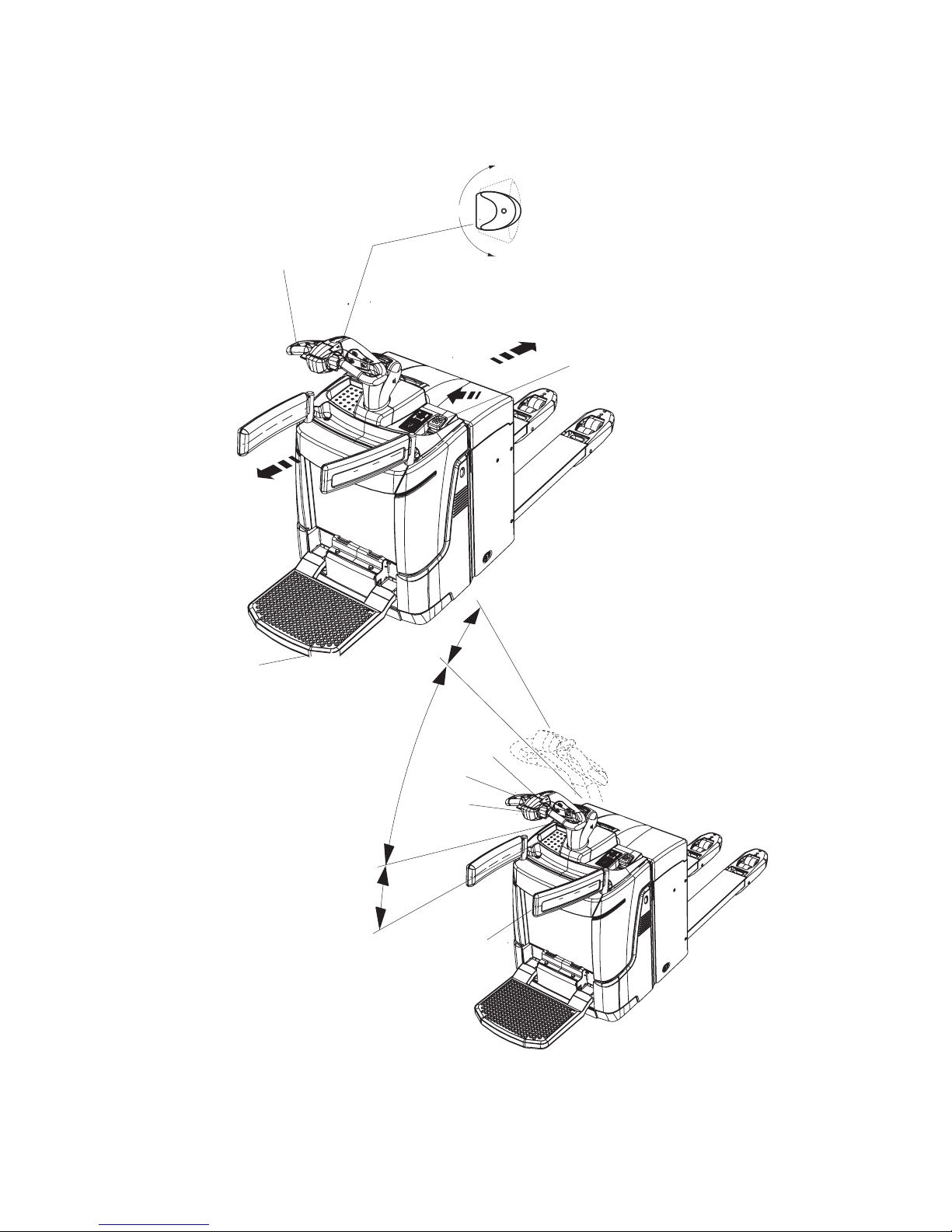
75
02.15 EN
R
V
R
V
0
B
BB
F
5
48
8
10
6
5
48
11
Page 77

02.15 EN
76
4.5.1 Changing direction during travel
CAUTION!
Danger when changing direction during travel
Changing direction during travel causes the truck to decelerate sharply. When the
truck changes direction, it can start travelling at high speed in the opposite direction
unless the travel switch is released in time.
XAfter setting off in the opposite direction, apply the travel switch gently or not at all.
XDo not perform any sudden steering operations.
XAlways face in the direction of travel.
XMaintain an adequate overview of the route you are travelling.
Changing direction during travel
Procedure
• Set the travel switch (5) to the opposite direction while travelling.
The truck decelerates until it starts to travel in the opposite direction.
Page 78

77
02.15 EN
4.6 Steering
Procedure
• Move the tiller (6) to the left or right.
The truck is steered in the required direction.
4.7 Brakes
WARNING!
Accident risk
The brake pattern of the truck depends largely on the ground conditions.
XThe operator must take into account the travel route conditions when braking.
XBrake with care to prevent the load from slipping.
XAllow for increased braking distance when travelling with an attached load.
XUse the service brake in emergencies.
CAUTION!
XIn hazardous situations swing the tiller to the brake position or press the emergency
disconnect switch.
The truck can brake in three different ways:
– By using the service brake (brake zone B).
– With the coasting brake.
– By inversion braking (braking and changing direction).
Page 79

02.15 EN
78
4.7.1 Braking with the service brake
Procedure
• Move the tiller (6) up or down to one of the brake zones (B).
The truck brakes to a halt regeneratively via the service brake.
Z When braking regeneratively, energy is returned to the battery, ensuring a longer
service time.
4.7.2 Braking with the coasting brake
Procedure
• If the travel switch (5) is set to (0), the truck automatically brakes regeneratively.
The truck brakes to a halt regeneratively via the coasting brake.
Z When braking regeneratively, energy is returned to the battery, ensuring a longer
service time.
4.7.3 Inversion braking
Procedure
• Set the travel switch (5) to the opposite direction while travelling, see "Changing
direction during travel" on page 76.
The truck brakes regeneratively until it starts to move in the opposite direction.
4.7.4 Parking brake
Z The mechanical brake applies automatically when the truck comes to rest.
Page 80

79
02.15 EN
4.8 Load handler raise/lower
WARNING!
Accident risk when lifting and lowering
Other people can be injured in the truck's hazardous area.
The hazardous area is defined as the area in which people are at risk from the
movement of the truck including the load handler, etc. This also includes areas which
can be reached by falling loads, operating equipment, etc.
Apart from the driver (in the normal operating position) there should be no other
people in the truck's hazardous area.
XInstruct other people to move out of the hazardous area of the truck. Stop working
with the truck if people do not leave the hazardous area.
XIf people do not leave the hazardous area despite the warning, prevent the truck
from being used by unauthorised people.
XOnly carry loads that have been secured and positioned in accordance with
regulations. Use suitable precautions to prevent parts of the load from tipping or
falling down.
XNever exceed the maximum loads specified on the capacity plate.
XDo not stand on the load handler.
XDo not lift other people on the load handler.
XNever reach or climb into moving truck parts.
XDo not climb onto parts of the building or other trucks.
NOTE
If the operator platform is folded down, the driver must be standing on it in order for
lifting and lowering to be enabled.
Page 81

02.15 EN
80
4.8.1 Raising the load handler
Requirements
– Prepare the truck for operation, see
"Preparing the truck for operation" on page 62.
Procedure
• Press the “Raise load handler ” button (50) until you reach the desired lift height.
NOTE
Risk of material damage to the hydraulic unit
When the mechanical end stop of the load has been reached, release the "Raise load
handler" button. Otherwise the hydraulic unit could suffer material damage.
The load handler is raised.
Ergonomic lift (
o
) (ERE C20)
When the "Load handler lift" (50) button is pressed when the load handler is loaded,
support arm lift is raised first and then mast lift, see page 85.
4.8.2 Lowering the load handler
Requirements
– Prepare the truck for operation, see "Preparing the truck for operation" on page 62.
Procedure
• Press the “Lower load handler” button (49) until you reach the desired lift height.
The load handler is lowered.
Ergonomic lift (
o
) (ERE C20)
When the "Load handler lower" (49) button is pressed when the load handler is
loaded, main lift is lowered first and then support arm lift, see page 85.
49
50
49
50
o
o
Page 82

81
02.15 EN
4.9 Lifting, transporting and depositing loads
WARNING!
Unsecured and incorrectly positioned loads can cause accidents.
Before lifting a load unit, the driver must make sure that it has been correctly
palletised and does not exceed the truck’s capacity.
XInstruct other people to move out of the hazardous area of the truck. Stop working
with the truck if people do not leave the hazardous area.
XOnly carry loads that have been correctly secured and positioned. Use suitable
precautions to prevent parts of the load from tipping over or falling off the truck.
XDamaged loads must not be transported.
XNever exceed the maximum loads specified on the load diagram.
XNever stand underneath a raised load handler.
XDo not stand on the load handler.
XDo not lift other people on the load handler.
XInsert the load handler as far as possible underneath the load.
CAUTION!
XDo not lift long loads at an angle.
NOTE
Adapt a slower speed when stacking and retrieving.
Page 83

02.15 EN
82
4.9.1 Raising a load
Requirements
– Load correctly palletised.
– Load weight matches the truck's capacity.
– Load handler evenly loaded for heavy loads.
Procedure
• Drive the truck carefully up to the pallet.
• Drive the load handler slowly into the pallet until the pallet is against the back of the
load handler (see graphic to the right).
Z The load must not extend by more than 50 mm beyond the load handler tips.
• Raise the load handler until the desired height is reached, (see page 80).
The load is being raised.
NOTE
Risk of material damage to the hydraulic unit
When the mechanical stops of the load handler have been reached, release the "raise
load handler" button. Otherwise the hydraulic unit may suffer material damage.
Ergonomic lift (
o
) (ERE C20)
When the "Load handler lift" (50) button is pressed when the load handler is loaded,
support arm lift is raised first and then mast lift, see page 85.
o
Page 84

83
02.15 EN
4.9.2 Transporting a load
Requirements
– Load raised correctly.
– ERE 120:
Raise the forks completely from the ground to transport correctly (approx. 150 - 200
mm above the ground).
– ERE C20:
Raise the forks completely from the ground to transport correctly (approx. 150 - 500
mm above the ground ). Do not travel with a raised load (>500 mm).
– Good ground conditions.
Procedure
• Accelerate and decelerate with care.
• Adapt your travel speed to the conditions of the route and the load you are
transporting.
• Travel at a constant speed.
• Be prepared to brake at all times:
• Brake gently in normal circumstances.
• Only stop suddenly in dangerous situations.
• Watch out for other traffic at crossings and passageways.
• Always travel with a lookout at blind spots.
• Do not travel across or at an angle on inclines. Do not turn on slopes and inclines,
and always drive with the load facing uphill (see graphic).
Page 85

02.15 EN
84
4.9.3 Depositing a load
CAUTION!
Loads must not be set down on transport or escape routes, in front of safety
installations or factory equipment that must be accessible at all times.
Requirements
– Storage location suitable for storing the load.
Procedure
• Drive the truck carefully up to the storage location.
• Lowers the load handler.
Z To avoid damaging the load and the load handler, avoid setting the load down
abruptly.
• Lower the load handler so that it is clear of the load (see page 80).
• Carefully drive the load handler out from beneath the pallet.
The load is deposited.
NOTE
Avoid depositing the load suddenly to avoid damaging the load, load handler and the
rack.
Ergonomic lift (
o
) (ERE C20)
When the "Load handler lower" (49) button is pressed when the load handler is
loaded, main lift is lowered first and then support arm lift, see page 85.
o
Page 86

85
02.15 EN
4.10 Ergonomic Lift (o) (ERE C20)
For lifting and lowering, the truck is equipped with support arm lift (initial lift) with the
maximum lift capacity and mast lift (high lift) with a lower lift capacity, see "Truck
capacity plate" on page 32.
Raises the load handler
When the "Load handler lift" (50) button is pressed when the load handler is loaded,
support arm lift is raised first and then mast lift, see "Raising the load handler" on
page 80.
Lowers the load handler
When the "Load handler lower" (49) button is pressed when the load handler is
loaded, main lift is lowered first and then support arm lift, see "Lowering the load
handler" on page 80.
Lifting, transporting and depositing loads
Do not travel with a raised load (>500 mm). Lower the forks for proper transport
(approx. 150 - 500 mm above the ground), see page 83.
Raising, transporting and depositing loads see page 81.
Use as an elevated work table
The raised load handler can be used as an elevated work table when the truck is
switched off, see page 86.
o
Page 87

02.15 EN
86
4.10.1 Use as a Lift Work Table
The load handler can remain in a raised position to be used as a lift work table when
the truck is switched off, provided the operator is close to the truck.
Z Immediate vicinity of the truck is when the operator is able to respond to
malfunctions or attempts to use the truck by unauthorised persons immediately.
Observe national regulations and local operating conditions.
WARNING!
A raised load handler can cause accidents
A stationary truck with a raised load handler is potentially hazardous in work areas.
XPrevent any risk to personnel and materials.
XNever load or discharge loads manually with a raised load handler in areas that are
hazardous, with limited visibility or insufficient lighting.
XPark the truck securely when leaving it, see page 65.
WARNING!
Risk of accident when the raised load handler slowly lowers of its own accord
The raised load handler can lower independently due to internal leakage. According
to DIN EN ISO 3691-1 the load handler may lower by up to 100 mm during the first
10 minutes at the rated capacity with the hydraulic oil at normal operating
temperature.
XNever stand underneath a raised load handler.
WARNING!
Risk of injury from falling loads
Falling loads can cause injuries.
XNever stand underneath a raised load handler.
XNever manually load or unload loads that could fall on the operator without
additional safety devices at heights greater than 1800 mm.
XAlways load loads so that they cannot fall off or accidentally shift.
XSecure low or small-item loads e.g. by wrapping them in film.
XDo not manually load or unload loads that are not correctly packed or have shifted
as well as loads with damaged pallets or damaged stacking containers.
Use as a lift work table
Requirements
– Storage spare suitable for manual loading or discharging of loads.
Procedure
• Drive the truck carefully up to the storage location.
• Press the “Raise load handler ” button (50) until you reach the desired lift height.
• Switch off the truck.
Loads can be loaded or discharged manually with the load handler raised.
Page 88

87
02.15 EN
Page 89

02.15 EN
88
5 Troubleshooting
This chapter enables the operator to localize and rectify basic faults or the results of
incorrect operation himself. When trying to locate a fault, proceed in the order shown
in the remedy table.
Z If, after carrying out the following remedial action, the truck cannot be restored to
operation or if a fault in the electronics system is displayed with a corresponding
error code, contact the manufacturer’s service department.
Troubleshooting must only be performed by the manufacturer’s customer service
department. The manufacturer has a service department specially trained for these
tasks.
In order for customer services to react quickly and specifically to the fault, the
following information is essential:
- Truck serial number
- Event message from the display unit (if applicable)
- Error description
- Current location of truck.
Page 90

89
02.15 EN
5.1 Truck does not start
Possible cause Corrective measures
Battery connector not plugged in. Check the battery connector
and connect if necessary.
Emergency disconnect switch pressed Unlock the emergency disconnect switch
Key switch set to O Set the key switch to “I”
Battery charge too low Check battery charge,
charge the battery if necessary
Faulty fuse Check the fuses, see page 143
Incorrect ISM access module (o)
transponder used
Use correct transponder
Incorrect CANCode (o) PIN entered Enter correct PIN, see page 97
Tiller (folding platform) not in brake
position when switching on the truck
(for CanDis (o) the event message E0914 appears)
Swing the tiller into the top or the bottom
brake zone, see page 78
Only one side arm is folded out (with
CanDis (o) the event message E-1926 is
shown)
Fold both side arms in/out.
Operating sequence not observed (with
CanDis (o) the event message E-1908 is
shown)
1. Step on platform.
2. Press the travel switch and move the
tiller into the working position if
necessary.
"Raise load handler" / "Lower load
handler" button not in home position when
truck switched on (for CanDis (o) event
message E-2951 appears)
Do not press button
Travel switch not in home position when
truck switched on (for CanDis (o) event
message E-1901 appears)
Do not apply travel switch
Collision safety switch applied when truck
switched on (for CanDis (o) event
message E-1914 appears)
Do not apply collision safety switch
Page 91

02.15 EN
90
5.2 Load cannot be lifted
Possible cause Corrective measures
Truck not operational Carry out all measures listed under “Truck
does not start”
Hydraulic oil level too low Check the hydraulic oil level, see
page 142
Battery discharge monitor has switched
off
Charge the battery, see page 44
Faulty fuse Check the fuses, see page 143
Excessive load Note maximum capacity, see data plate
Tiller (folding platform) not in brake
position when switching on the truck
(for CanDis (o) the event message E0914 appears)
Set the tiller to the top or bottom brake
zone, see page 78
Only one side arm is folded out (with
CanDis (o) the event message E-1926 is
shown).
Fold both side arms in/out.
Operating sequence not observed (with
CanDis (o) the event message E-1908 is
shown)
1. Step on platform.
2. Press the travel switch and move the
tiller into the working position if
necessary.
"Raise load handler" / "Lower load
handler" button not in home position when
truck switched on (for CanDis (o) event
message E-2951 appears)
Do not press button
Travel switch not in home position when
truck switched on (for CanDis (o) event
message E-1901 appears)
Do not apply travel switch
Collision safety switch applied when truck
switched on (for CanDis (o) event
message E-1914 appears)
Do not apply collision safety switch
Page 92

91
02.15 EN
6 Operating the truck without its own drive system
Z With the right optional equipment (o) it is possible to switch the truck to emergency
operation via the GF60 service key: The brakes are released electrically and the
truck can move without its own drive system, see "Emergency operation with
service key GF60" on page 93.
6.1 Release and activate the drive wheel brake
WARNING!
Accidental truck movement
When the brakes are de-activated the truck must be parked on a level surface, since
the brakes are no longer effective.
XDo not release the brake on slopes or inclines.
XDo not park the truck with the brake released.
XApply the brake again when you reach your destination.
CAUTION!
Open covers can cause injury and accidents
XThe covers (side panels, drive compartment cover etc.) must be closed during
operation.
Releasing the brake
Tools and Material Required
– Two M5X16 screws
– Spanner wrench
Procedure
• Turn of the key switch, CanCode (o).
• Pull the Emergency Disconnect switch.
• Prevent the truck from rolling away.
• Lift up the front cover (70) and put it to one side, see "Front cover disassembly" on
page 137.
• Insert two M5X16 screws as far as the stop and lift up the anchor plate (57).
The brake is now released and the truck can be moved.
Applying the brake
Procedure
• Unscrew the two M5X16 screws again.
• Refit the front panel.
Braking is now restored again.
Page 93

02.15 EN
92
WARNING!
Only return the truck to service when you have identified and rectified the fault.
57
Page 94

93
02.15 EN
7 Optional equipment
7.1 Emergency operation with service key GF60
WARNING!
The truck can move accidentally when the brake is released
XThe GF60 service key must not remain on the truck during normal operation.
XThe service key should only be used by an authorised person (e.g. warehouse
manager).
XExtreme caution is required on a ramp or incline as the truck could roll away when
the brake is released.
XWhen the key switch is set to position 2 (brake released), the truck cannot brake
through inversion braking or the tiller switch.
Operating the truck without its own drive system.
Requirements
– Truck prevented from rolling away.
– Charged battery in truck.
Tools and Material Required
– GF60 service key with lock bar
Procedure
• Insert the GF60 service key in the key switch.
Z The service key GF60 with a lock bar can only be inserted and turned on one side.
If inserted in the wrong direction the key will not turn.
• Turn service key to position 1.
• Move the lock bar on the head of the key.
• Turn service key to position 2.
CAUTION!
The brake is now released
XThe truck can only brake by turning the service key to position 1 or pressing the
Emergency Disconnect.
The truck can be operated without its own drive system.
GF 60
Page 95

02.15 EN
94
Parking the truck securely
Procedure
• Set the key switch to the “0” position and remove the key.
Z When you switch back from level 2 to level 1 the bar returns to its original position.
The brake is now activated again.
Z The GF30 key without a bar is designed for normal truck operation.
It can be inserted on either side and can only be turned to position 1
of the key switch.
GF 30
Page 96

95
02.15 EN
7.2 CanCode Keypad (o)
7.2.1 Code lock
The code lock allows a user or group of users to assign an individual user code.
Travel programs can also be assigned to the individual user codes. The user code is
configured with a master code and is described in the following sections in this
chapter.
When you have entered the valid user code the truck will be operational. The truck
will be able to perform travel, steering and hydraulic operations.
When you have entered the valid master code, the truck will be switched on. Travel
operations are, however, inhibited. The truck will be able to perform hydraulic
operations. The code lock is in programming mode. When you enter one of the
following parameters, the settings in the code lock can be changed.
Newly supplied trucks have the code indicated on a sticker. When using the truck for
the first time change the master and user codes and remove the sticker.
– User code factory setting: 2-5-8-0
– Master code factory setting: 7-2-9-5
WARNING!
Lack of usage restrictions can result in accidents
If the same codes are used to operate different trucks, there is no restriction of usage
for the operators or operator groups.
XWhen allocating the codes, ensure rider trucks are given a different code from
pedestrian trucks.
Parameter Description
0-0-0
– Change master code
(see "Changing the master code" on page 98)
0-0-1
– Add user codes
(see "Add operator code" on page 100)
0-0-2
– Change a user code
(see "Change operator code" on page 102)
0-0-3
– Delete a user code
(see "Delete individual user codes" on page 104)
0-0-4
– Delete all user codes
(see "Delete all user codes," on page 106)
0-1-0
– Switch on the truck automatically
(see "Setting the automatic truck cutout (timeframe)" on
page 108)
0-2-4
– Assign travel programs to the user codes
(see "Assigning the travel program" on page 110)
o
Page 97

02.15 EN
96
The keypad consists of 10 digit keys, a Set key (61)
and a o key (63).
Digit keys
The digit keys are used to enter the user or master
code and select the travel program.
The green LEDs of the digit keys 1, 2 and 3 (58, 59,
60) show the travel program setting.
o
key
Pressing the o key switches the truck off and sets it
to "non operational" status.
The o key indicates the follow operating conditions via a red / green LED (62):
– Code lock function (commissioning the truck).
– Error display configuring the user code.
– Adjusting the travel program depending on the setting and truck.
– Setting and changing parameters.
SET key
When you change the parameters the SET key (61) acts as a confirmation key.
1 2 3
4 5 6
7 8 9
0
Set
61
58 59 60
6362
o
Page 98

97
02.15 EN
7.2.2 Preparing the truck for operation with the keypad (CanCode)
Preparing the truck for operation by entering a valid operator code
Procedure
• Pull the Emergency Disconnect to unlock it, see "Emergency Disconnect" on
page 69.
The LED (62) lights up red.
• Enter the operator code with the digit keys.
When you have entered a valid operator code the LED (62) lights up green, the
travel program selected is indicated by the corresponding LEDs (58,59,60) and the
truck is switched on.
Z If the LED (62) flashes red this means the wrong code has been entered. Enter the
code again.
The Set key (61) has no function in operating mode.
7.2.3 Switching off the truck with the keypad (CanCode)
Switching off the truck
Procedure
• Press the O key (63).
The truck is switched off and the LED (62) is lit red.
Z The truck can cut out automatically after a specified time. If no travel, steering or
hydraulic operations are performed within a set time, the truck switches off
automatically. When you enter a valid code again the truck will be operational. The
code lock parameter responsible for automatic cutout must be set, see "Setting the
automatic truck cutout (timeframe)" on page 108.
Fixed cutout time (
o
)
An automatic truck cutout is factory-set. The cutout time is factory-set to 5 minutes.
Z This setting can be changed if required.
o
Page 99

02.15 EN
98
7.2.4 Changing the master code
Z To change the length of the master code you must follow the procedure in "Choose
length of the new master code (4-6 digit) and add user codes", see "Choose length
of the new master code (4-6 digit) and add user codes" on page 107. If there are
still user codes stored in the code lock, the master code to be changed must be the
same length as the saved user codes.
Requirements
– To prepare the truck for operation, see "Preparing
the truck for operation with the keypad (CanCode)"
on page 97.
Procedure
• Press the O key (63).
• Enter the valid master code with the digit keys.
When you enter the valid master code the LED
(62) flashes green.
• Enter the parameters 0-0-0 with the digit keys.
• Confirm with the SET key (61).
The LEDs (58,62) flash green.
• Enter the valid master code again with the digit keys.
• Confirm with the SET key (61).
The LEDs (59,62) flash green.
• Enter the valid master code with the digit keys.
Z The new master code must be different from existing user codes.
• Confirm with the SET key (61).
The LEDs (60,62) flash green.
• Enter the new master code again with the digit keys.
• Confirm with the SET key (61).
Wait until the LED (62) flashes green. The setting is saved.
• Press the O key (63).
The truck is switched off and the LED (62) is lit red.
• Check the new master code:
• Switch on the truck with the new master code, see "Preparing the truck for
operation with the keypad (CanCode)" on page 97
When you enter the valid master code the LED (62) flashes green.
• Press the O key (63).
The truck is switched off and the LED (62) is lit red.
1 2 3
4 5 6
7 8 9
0
Set
61
58 59 60
6362
Page 100

99
02.15 EN
Error displays changing the master code
For the following events the LED (62) flashes red:
Cause Remedy
– New master code is already
occupied by a user code
– Switch off the truck, see "Switching off the truck
with the keypad (CanCode)" on page 97.
– Choose a different master code, see "Changing
the master code" on page 98.
– Change the user code so that the required
master code can be used, see "Change
operator code" on page 102.
– Delete the user code so that the required
master code can be used, see "Delete
individual user codes" on page 104.
– The master codes to be
changed do not match
– Switch off the truck, see "Switching off the truck
with the keypad (CanCode)" on page 97.
– Enter the master code again, see "Changing the
master code" on page 98.
– The master code entered is
not the same length as the
user code
– Switch off the truck, see "Switching off the truck
with the keypad (CanCode)" on page 97.
– Repeat the entry, making sure that the length of
the master code matches that of the user code.
 Loading...