

Page 1
AMW 22 / AMW 22p / AMW 22ps
12.14
Operating instructions
51119800
11.19
en-GB
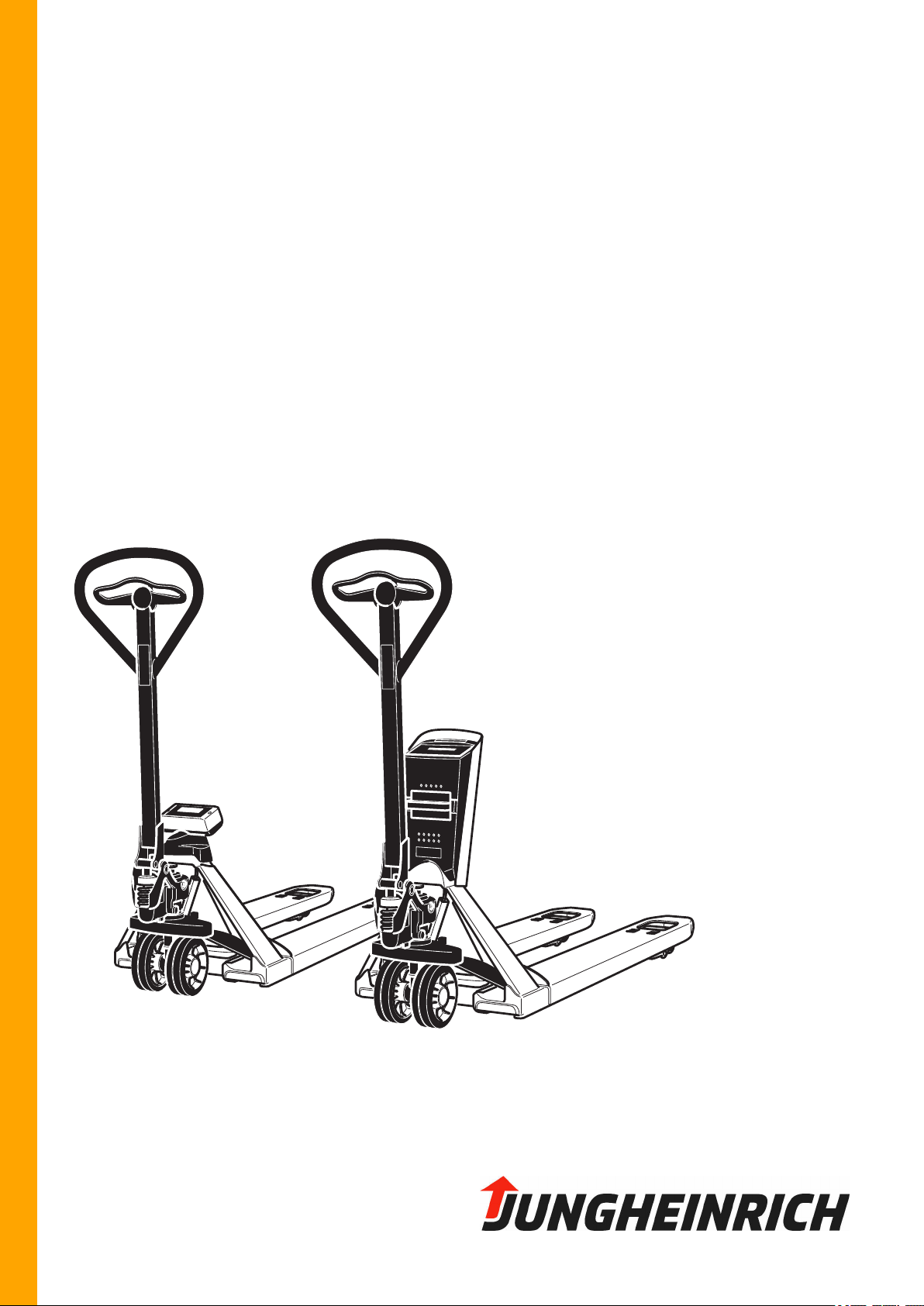
AMW 22
AMW 22p
AMW 22ps
Page 2

2
Page 3
Declaration of Conformity
Manufacturer
Jungheinrich AG, 22039 Hamburg, Germany
Description
Industrial truck
Type Option Serial no. Year of
manufacture
AMW 22
AMW 22p
AMW 22ps
On behalf of
Date
EU DECLARATION OF CONFORMITY
The undersigned hereby declare that the powered truck described in detail complies
with the current versions of European Directives 2006/42/EG (Machinery Directive)
and 2014/30/EU (Electromagnetic Compatibility - EMC). The manufacturer is
authorised to compile the technical documentation.
11.19 en-GB
3
Page 4

11.19 en-GB
4
Page 5

Foreword
Notes on the operating instructions
The present ORIGINAL OPERATING INSTRUCTIONS are designed to provide
sufficient instruction for the safe operation of the industrial truck. The information is
provided clearly and concisely. The chapters are arranged by letter and the pages
are numbered continuously.
The operator manual details different industrial truck models. When operating and
servicing the industrial truck, make sure that the particular section applies to your
truck model.
Our trucks are subject to ongoing development. We reserve the right to alter the
design, equipment and technical features of the system. No guarantee of particular
features of the truck should therefore be assumed from the present operating
instructions.
Safety notices and text mark-ups
Safety instructions and important explanations are indicated by the following
graphics:
Z
DANGER!
Indicates an extremely hazardous situation. Failure to comply with this instruction will
result in severe irreparable injury and even death.
WARNING!
Indicates an extremely hazardous situation. Failure to comply with this instruction
may result in severe irreparable injury and even death.
CAUTION!
Indicates a hazardous situation. Failure to comply with this instruction may result in
slight to medium injury.
NOTICE
Indicates a material hazard. Failure to comply with this instruction may result in
material damage.
Used before notices and explanations.
Indicates standard equipment
t
Indicates optional equipment
o
11.19 en-GB
5
Page 6

11.19 en-GB
6
Page 7

11.19 en-GB
Contents
.
A Correct Use and Application 9
.
1 General 9
2 Correct application 9
3 Approved application conditions 9
4 Proprietor responsibilities 10
5 Adding attachments and/or optional equipment 10
.
B Truck Description 11
.
1 Application 11
2 Calibrated weighing system (AMW 22p / AMW 22ps) 11
3 Assemblies and Functional Description 12
3.1 Truck Component Overview 12
3.2 Weighing System Component Overview 13
4 Technical Specifications 14
4.1 Performance data 14
4.2 Weighing System Weight Display 14
4.3 Weighing Variance of the Weighing System 15
4.4 Dimensions 16
4.5 Weights 17
4.6 Batteries 17
4.7 Tyre type 17
4.8 Operating conditions 18
4.9 Identification Points and Data Plates 19
4.10 Wind loads 20
.
C Transport and Commissioning 21
.
1 Lifting by crane 21
2 Transport 22
3 Using the Truck for the First Time 23
.
D Batteries/Accumulators - Replacement/Charging 25
.
1 Safety Regulations for Handling Batteries and Accumulators 25
2 Safety regulations for handling lithium-ion batteries 27
2.1 Safety regulations 27
2.2 Potential hazards 28
2.3 Charging the battery 32
2.4 Battery lifetime and maintenance 33
2.5 Storing the battery 33
2.6 Faults 33
2.7 Disposal and transport of a lithium-ion battery 35
2.8 Hazard and Safety Instruction Phrases 39
3 Power Supply AMW 22 41
3.1 General information 41
3.2 Replacing batteries 41
4 Power Supply AMW 22p 43
4.1 General information 43
4.2 Charging the battery 43
7
Page 8

5 AMW 22ps power supply 45
5.1 General information 45
5.2 Battery charge status 46
5.3 Charging the battery 47
.
E Operation 49
.
1 Safety Regulations for the Operation of Forklift Trucks 49
2 Displays and Controls 51
3 Starting up the truck 52
3.1 Checks and Operations to Be Performed Before Starting Daily Work 52
4 Industrial Truck Operation 53
4.1 Safety regulations for truck operation 53
4.2 Parking the truck securely 54
4.3 Pushing/Pulling 55
4.4 Steering 55
4.5 Brakes 56
4.6 Lifting, transporting and depositing loads 57
4.7
4.8
4.9 AMW 22ps weighing system 76
4.10
5 Troubleshooting 102
5.1 Load cannot be lifted 102
.
AMW 22 / AMW 22p Standard Weigher (t) 60
AMW 22p Weigher, Special Version (o) 66
On-Board Printer (o) 101
F Checking the Industrial Truck 103
.
1 Spare Parts 103
2 Operational Safety and Environmental Protection 103
3 Safety Regulations for Checks 104
4 Lubricants and Lubrication Schedule 106
4.1 Handling consumables safely 106
4.2 Lubrication Schedule 108
4.3 Consumables 108
5 Checks 109
5.1 Preparing the Truck for Checking 109
5.2
6 Decommissioning the Industrial Truck 110
6.1 Prior to decommissioning 110
6.2 Restoring the truck to service after decommissioning 110
7 Safety tests to be performed at intervals and after unusual incidents 111
8 Final de-commissioning, disposal 111
9 Operating Company Checks 112
(o) Check and Adjust Foot-Activated Parking Brake 109
11.19 en-GB
8
Page 9

A Correct Use and Application
1 General
The truck must be used, operated and serviced in accordance with the present
instructions. All other types of use are beyond its scope of application and may result
in damage to personnel, the industrial truck or property.
2 Correct application
NOTICE
The maximum load and the maximum permissible load distance given on the data
plate must be observed.
The load must be fully supported by the load handler, evenly distributed and raised
completely from the ground.
The following operations are in accordance with regulations and are permitted:
– Lifting and lowering loads.
– Transporting lowered loads.
The following operations are prohibited:
– Carrying and lifting passengers.
– Pushing or pulling loads.
– Transverse handling of long loads.
3 Approved application conditions
– Operation in industrial and commercial environments.
– Permissible temperature range see page 18.
– Operation only on secure, level surfaces with sufficient load-bearing capacity.
– Operation only on routes that are visible and approved by the operating company.
– Do not negotiate inclines.
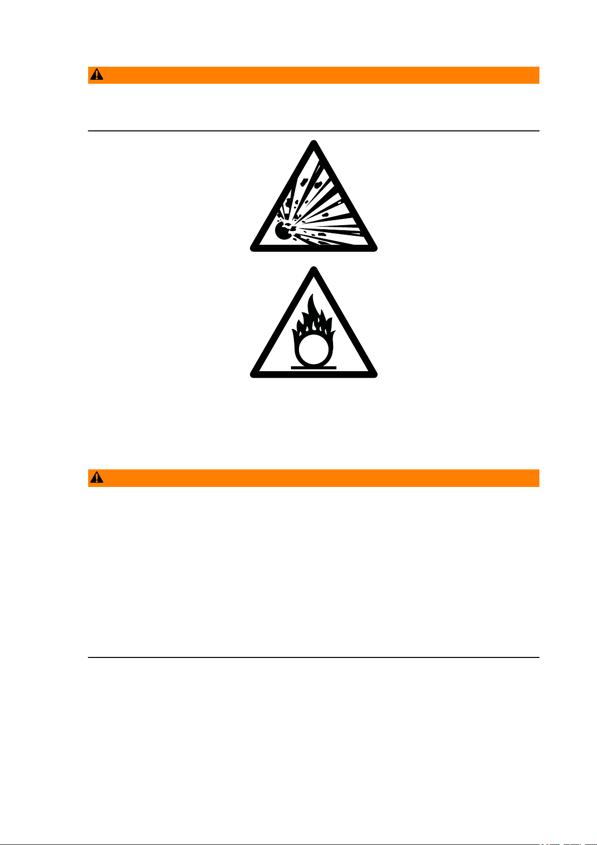
WARNING!
Use under extreme conditions
Using the truck under extreme conditions can result in malfunctions and accidents.
Special equipment and authorisation are required if the truck is to be constantly
u
used in extreme conditions, especially in dusty or corrosive atmospheres.
The truck cannot be used in areas at risk of explosion.
u
In adverse weather conditions (thunder, lightning) the industrial truck must not be
u
operated outside or in endangered areas.
11.19 en-GB
9
Page 10

4 Proprietor responsibilities
For the purposes of the present operating instructions the “operating company” is
defined as any natural or legal person who either uses the industrial truck himself, or
on whose behalf it is used. In special cases (e.g. leasing or renting) the proprietor is
considered the person who, in accordance with existing contractual agreements
between the owner and user of the industrial truck, is charged with operational
duties.
The proprietor must ensure that the industrial truck is used only for the purpose it is
intended for and that danger to life and limb of the user and third parties are
excluded. Furthermore, accident prevention regulations, safety regulations and
operating, servicing and repair guidelines must be followed. The operating company
must ensure that all users have read and understood these operating instructions.
NOTICE
Failure to comply with the operating instructions invalidates the warranty. The same
applies if improper work is carried out on the truck by the customer or third parties
without the permission of the manufacturer.
5 Adding attachments and/or optional equipment
The mounting or installation of additional equipment which affects or enhances the
performance of the industrial truck requires the written permission of the
manufacturer. Local authority approval may also need to be obtained.
Local authority approval however does not constitute the manufacturer’s approval.
10
11.19 en-GB
Page 11

B Truck Description
1 Application
The pallet truck is designed to transport goods on level surfaces. Open bottom
pallets or roll cages can be lifted.
The rated capacity is indicated on the data plate or the capacity plate Qmax.
The weighing system provides the option of weighing loads, adding individual
weights and displaying a total weight. Current weighing data and entered data can
be issued on the on-board printer (o). The date and time are only issued if this option
has been activated.
2 Calibrated weighing system (AMW 22p / AMW 22ps)
The AMW22p / AMW 22ps industrial truck can be equipped with an optional
calibratable weighing system and manufacturer calibration in accordance with OIML
Approval Class III (European Approval No. T2782) in order to perform weighing
operations for commercial purposes.
The calibrated weighing system is approved separately by the notified body with a
serial number and is given an official inspection label. The inspection label confirms
the accuracy within the permissible calibration tolerance. The supplied declaration of
conformity must be retained. The area of validity of the EC calibration comprises the
EU state specified on the declaration of conformity. Weighing systems that are
currently in use are tested in accordance with the statutory provisions of the
respective EU country.
Z
If the validity period of the calibration is limited according to national regulations, the
owner of a truck with a calibrated weighing system bears sole responsibility for its
timely recalibration.
Significant geographical changes in location of the truck require a recalibration to be
performed before the weighing system can be operated.
NOTICE
The validity of the calibration becomes void in the event of damage to the truck,
manual intervention in the operation of equipment such as the housing opening, as
well as any damage or removal of the test plaques.
Calibratable weighing systems with deviations beyond the traffic error limit, an
exceeded reverification date or which have passed their calibration expiry date must
be taken out of service.
11.19 en-GB
11
Page 12
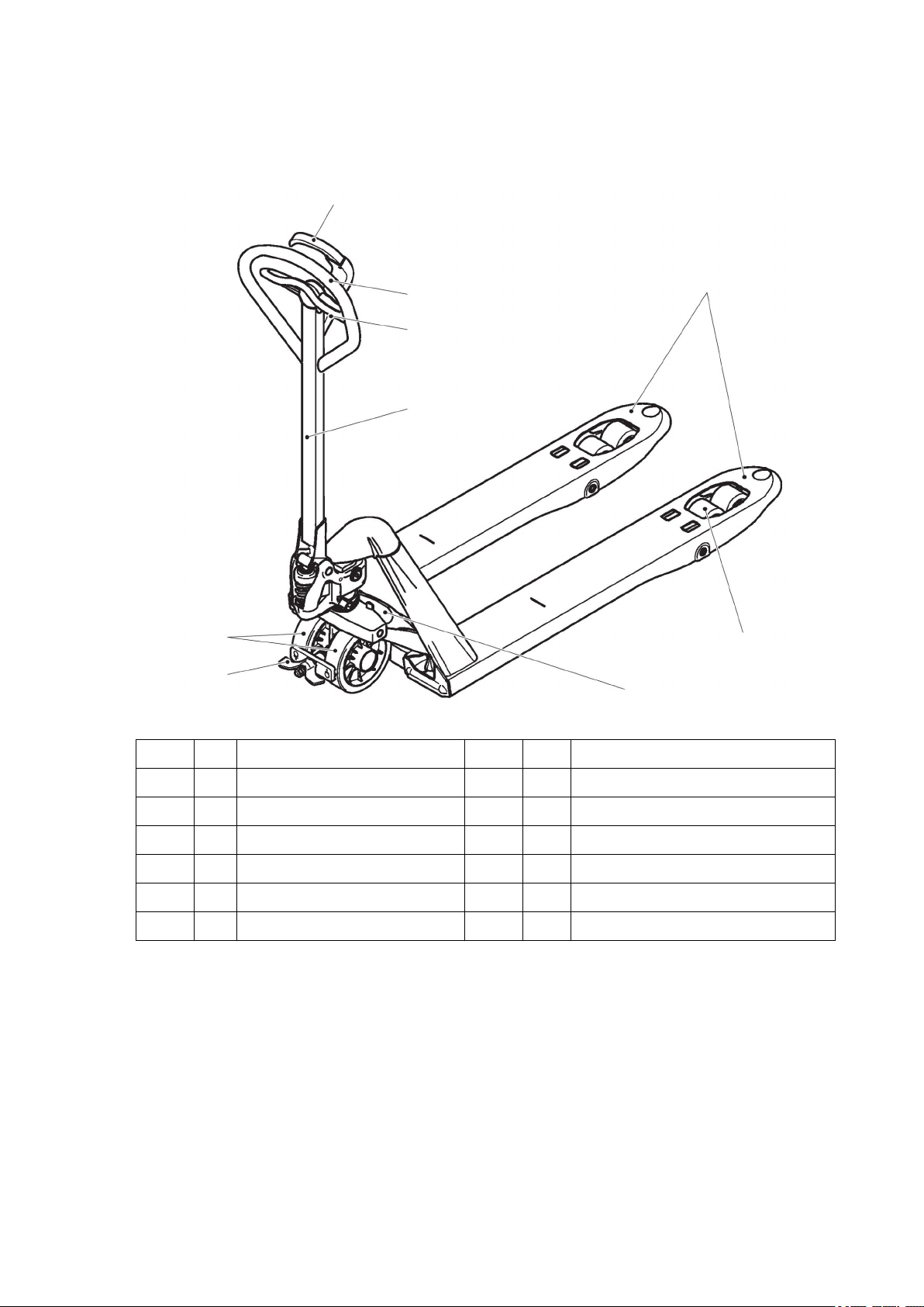
3 Assemblies and Functional Description
6
13452
798
3.1 Truck Component Overview
Item Description Item Description
1
2
3
4
5
Travel and parking brake 6
o
Load handler 7
t
Handle 8
t
“Lift/lower fork” handle 9
t
Tiller
t
Standard equipment
t
Steered wheels
t
Load wheels
t
Foot-activated parking brake
o
Data plate
t
Optional equipment
o
11.19 en-GB
12
Page 13
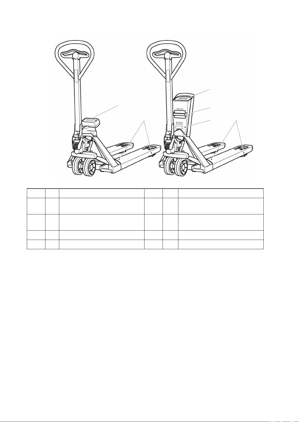
3.2 Weighing System Component Overview
1113101312
14
Item Designation Item Designation
10
Display and evaluation unit
t
13
t
Load cells
(AMW 22p / AMW 22ps)
11
Display and evaluation unit
t
14
On-board printer
o
(AMW 22)
12
Battery
t
Standard equipment
t
Optional equipment
o
3.2.1 Weight Detection
Four load cells are bolted to the load carrying frame and also to the load attachment
head. The load cells and the connection cable to the evaluation and display unit are
installed so that they are protected.
3.2.2 Evaluation and Display Unit
Weights, system statuses and quantities (o) are displayed. All functions of the
weighing system can be called up using the keys below the display. The zero setting
is performed automatically within set limits.
3.2.3
On-Board Printer (o)
11.19 en-GB
Individual weights, tare weights and total weights can be output on thermal paper, as
can quantities (o) with identification code numbers (o) and time of printing (o).
13
Page 14
4 Technical Specifications
Z
The technical specification is given according to the German guideline "Type sheets
for industrial trucks". Technical modifications and additions reserved.
4.1 Performance data
AMW 22 / AMW 22p /
Q Rated capacity 2200 kg
c Load centre distance 600 mm
x Load distance 890 mm
Lowering speed with / without load 90/20 mm/s
4.2 Weighing System Weight Display
AMW 22 and AMW 22p
Weight range Resolution of weight display
AMW 22 AMW 22p
(t)
AMW 22ps
AMW 22p
1)
(o)
1)
AMW 22p
Calibrated (o)
1)
0 to 200 kg 1.0 kg 0.2 kg 0.1 kg 0.5 kg (o)
200 to 500 kg 0.5 kg 0.2 kg
500 - 2000 kg (t)
500 - 2200 kg (o)
1.0 kg
0.5 kg 1.0 kg
AMW 22ps (from year of manufacture 2020)
Weight range Resolution of weight display
AMW 22ps (t)
1)
AMW 22ps
Calibrated (o)
1)
0 to 200 kg 0.2 kg 0.5 kg
200 to 500 kg 0.5 kg
500 - 2000 kg (t)
500 - 2200 kg (o)
1.0 kg 1.0 kg
1) Multi-range display: The resolution of the weight display depends on the weight.
During weighing out, the resolution does not change on passing the boundary to the
next lower weight range.
14
11.19 en-GB
Page 15

4.3 Weighing Variance of the Weighing System
AMW 22 Within a temperature range of -10 to +40°C, the maximum weighing
variance is 0.1% of the overall weighing range.
Z
AMW 22p
AMW 22ps
Outside the listed temperature range, weighing variances of up to 0.3% can occur.
Within a temperature range of -10 to +40°C the maximum weighing
variance is 0.1% of the measured weight.
11.19 en-GB
15
Page 16
4.4 Dimensions
s
e
W
a
x
h
14
b
11
b
10
b1= b
5
h
3
h
13
l
1
l
6
l
2
l
m
2
674 (AMW 22p / AMW 22ps)
y
c
Q
104°
104°
a/2=100
a/2=100
Ast = W
a+l6
-x+a
Designation AMW 22 / AMW 22p /
h3Lift
h13Lowered height
h14Height of tiller handle
y Wheelbase 1110 mm
s/e/l Fork dimensions 62/170/1150 mm
AMW 22ps
122 mm
86 mm
1234 mm
16
l1Overall length 1546
l2Length to fork face
396 mm
mm
11.19 en-GB
Page 17
Designation AMW 22 / AMW 22p /
AMW 22ps
b1Overall width
b5Outer fork distance
b10Track width, front
b11Track width, rear
Ast Working aisle width 1000x1200 transv. 1763 mm
Ast Aisle width 800x1200 length. 1813 mm
Wa Turning radius 1303 mm
4.5 Weights
Designation AMW 22 / AMW 22p /
Net weight 99/102 kg
Axle load, w.o. load front/rear 61/38 kg
Axle load, w. load front/rear (AMW 22) 578/1721 kg
4.6 Batteries
540 mm
540 mm
109 mm
370 mm
AMW 22ps
Truck Battery type Voltage/capacity
AMW 22 Alkaline (type AA) 4x1.5 V
AMW 22p Lead-gel battery
AMW 22ps Lithium-ion battery
4.7 Tyre type
AMW 22 / AMW 22p /
Tyre size, front Ø 170 x 50 mm
Tyre size, rear Ø 82 x 96 mm
Tyre size, rear (tandem wheels) Ø 82 x 62 mm
12 V/1.2 Ah
(rechargeable)
14.8 V/5 Ah
(rechargeable)
AMW 22ps
11.19 en-GB
17
Page 18

4.8 Operating conditions
– During operation: -10°C to 40°C
Ambient lighting
– - At least 50 Lux during operation
Z
Outside the listed temperature range, weighing variances of up to 0.3% can occur.
NOTICE
Rapid changes in temperature should be avoided as they can cause moisture to
condense within the electronics. When large temperature differences are
encountered, switch the weighing system off whilst it acclimatises.
18
11.19 en-GB
Page 19
4.9 Identification Points and Data Plates
9
16
15
222117
19
18
23
20
Item Model
9 Truck data plate
15 Plate - Operation / Lifting
16 Capacity Qmax
4.9.1 Data plate
Item Description Item Description
17 Model 21 Rated capacity (kg)
18 Year of manufacture 22 Manufacturer
11.19 en-GB
Z
19 Serial number 23 Manufacturer's logo
20 Net weight in kg
For queries regarding the truck or ordering spare parts always quote the truck serial
number (19).
19
Page 20

4.10 Wind loads
Wind forces can affect the stability of a truck when lifting, lowering and transporting
loads with large surface areas.
Light loads must be especially secured when they are subjected to wind forces. This
will prevent the load from sliding or falling.
Stop the truck in both cases.
20
11.19 en-GB
Page 21
C Transport and Commissioning
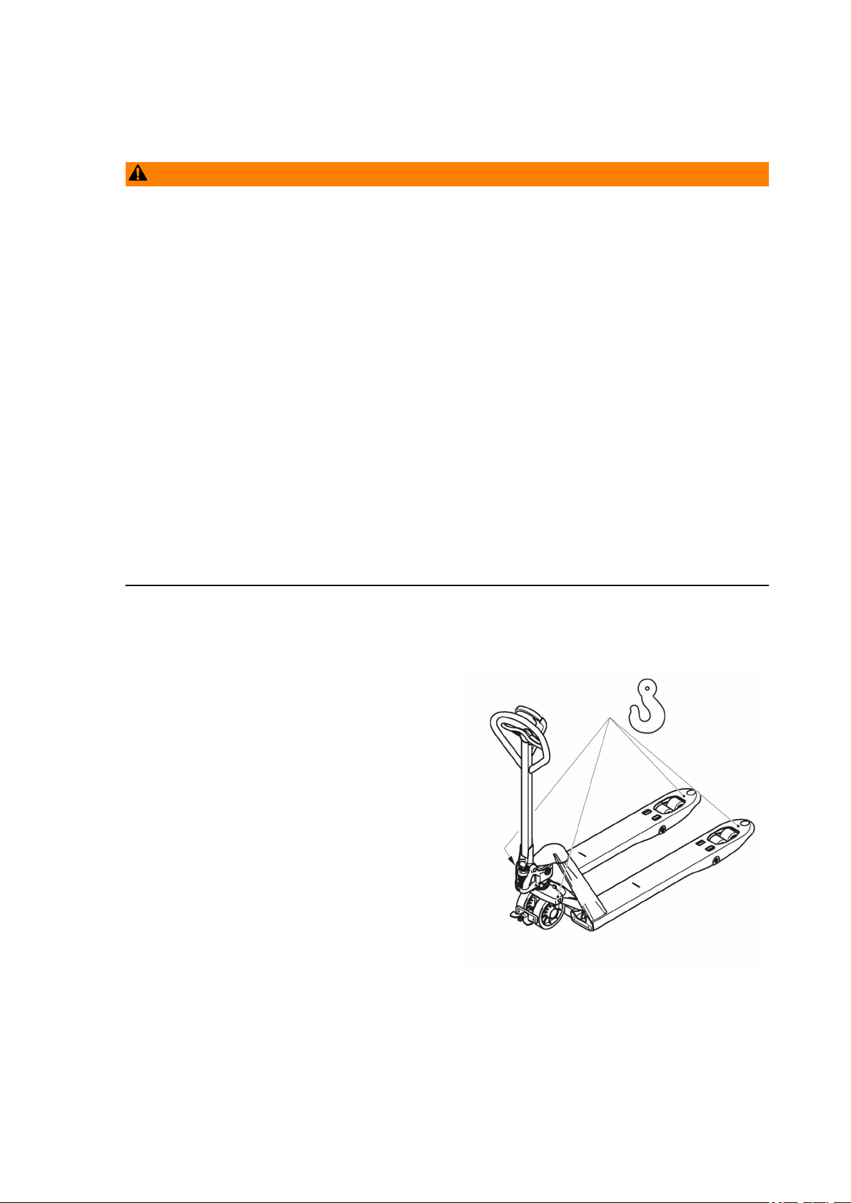
24
1 Lifting by crane
WARNING!
Improper loading by crane can result in accidents
Improper use or use of unsuitable lifting gear can cause the truck to crash when
being loaded by crane.
Prevent the truck from hitting other objects during lifting, and avoid uncontrolled
movements. If necessary, secure the truck with guide ropes.
The truck may be loaded only by people who are trained in using lifting
u
accessories and lifting gear.
Wear personal protective equipment (e.g. safety shoes, safety helmet, hi-vis
u
jacket, protective gloves) when loading by crane.
Do not stand under suspended loads.
u
Do not walk into or stand in a hazardous area.
u
Always use lifting gear with sufficient capacity (for truck weight, see truck data
u
plate).
Always attach the crane lifting gear to the prescribed attachment points and
u
prevent them from slipping.
Use the lifting accessories only in the prescribed load direction.
u
Crane lifting gear must be fastened in such a way that it does not come into
u
contact with any attachments when lifting.
Lifting the truck by crane
Requirements
– Park the truck securely, see page 54.
Tools and Material Required
– Lifting gear
– Crane lifting gear
Procedure
• Secure the crane lifting gear to the strap
points (24).
The truck can now be lifted by crane.
11.19 en-GB
21
Page 22
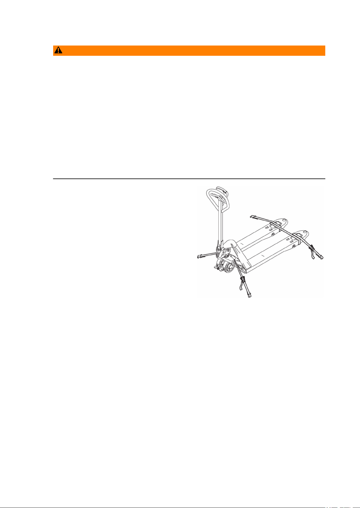
2 Transport
25
25
WARNING!
Accidental movement during transport
Improper fastening of the truck and mast during transport can result in serious
accidents.
Loading must only be performed by specialist personnel trained for this purpose.
u
The specialist personnel must be instructed in securing loads on road vehicles and
handling load securing devices. In each case correct measurements must be
taken and appropriate safety measures applied.
The truck must be securely fastened when transported on a lorry or a trailer.
u
The lorry or trailer must have fastening rings.
u
Use wedges to prevent the truck from moving.
u
Use only fastening belts with sufficient strength.
u
Use non-slip materials to securing the load aids (pallet, wedges, ...) e. g. non-slip
u
mats.
Securing the truck for transport
Requirements
– The truck is now loaded.
– The truck is now parked securely, see
page 54.
Tools and Material Required
– Lashing straps
Procedure
• Attach the lashing straps (25) to the
industrial truck and the transport vehicle
and tension sufficiently.
The truck can now be transported.
11.19 en-GB
22
Page 23

3 Using the Truck for the First Time
Procedure
• Check the equipment is complete.
The truck can now be started, see page 52.
Z
When the vehicle is parked, the surface of the tyres will flatten. The flattening will
disappear after a short period of operation.
11.19 en-GB
23
Page 24

24
11.19 en-GB
Page 25

D Batteries/Accumulators - Replacement/
Charging
1 Safety Regulations for Handling Batteries and
Accumulators
Maintenance personnel
Accumulators must only be charged and batteries only replaced by the operating
company. These operating instructions and the manufacturer’s instructions
concerning batteries and charging stations must be observed when carrying out the
work.
WARNING!
Risk of accidents and injury when handling batteries and accumulators
Batteries and accumulators contain chemicals that are poisonous and corrosive.
Avoid contact at all costs.
Do not dismantle or forcibly open batteries and accumulators.
u
Do not subject batteries and accumulators to heat, fire or direct sunlight.
u
Do not short-circuit batteries and accumulators. Store batteries and accumulators
u
so that no short circuits can occur through other batteries and accumulators or
metal objects.
Never use batteries or accumulators of different makes, capacity, size or type at
u
the same time in one truck.
Failure to comply could result in explosions!
u
Seek medical assistance immediately if you have swallowed a battery or
u
accumulator.
Do not subject batteries and accumulators to impacts.
u
Keep battery terminals and contacts clean and dry.
u
If a battery or accumulator is leaking, do not allow the liquid to come into contact
u
with the skin or eyes. If this has already happened, rinse the affected part with
plenty of water and seek medical assistance immediately.
Keep batteries and accumulators in a clean and dry environment, out of the reach
u
of children.
11.19 en-GB
Park the truck securely before carrying out any work on the batteries/accumulators
(see page 54).
25
Page 26
Battery disposal
NOTICE
Batteries must be disposed of in accordance with the relevant national
environmental protection regulations.
Used batteries are recyclable commodities. As indicated by the marking showing a
crossed-out waste bin, batteries must not be disposed of as domestic waste.
Return or recycling of batteries must be ensured in accordance with the Battery
Directive 2006/66/EG.
Used batteries must be treated as hazardous waste. Batteries marked with the
recycling symbol and the sign showing a crossed-out rubbish bin should not be
disposed of with ordinary household waste.
26
11.19 en-GB
Page 27

2 Safety regulations for handling lithium-ion batteries
2.1 Safety regulations
WARNING!
Unsuitable batteries without manufacturer approval can be dangerous.
Do not use any batteries without approval from the manufacturer.
u
The battery equipment must only be replaced with the manufacturer's
u
authorisation.
When inserting the battery, ensure that it is securely seated in the battery
u
compartment.
– Do not physically machine or modify the battery.
– Do not open, damage, penetrate or bend the battery.
– Do not throw the battery into a fire.
– Protect the battery from high temperatures and overheating.
– Protect the battery from solar irradiation.
– Keep the battery away from radiant sources and strong heat sources.
– The specified charging, operating and storage temperature ranges must be
observed.
Failure to comply with these safety instructions can result in fire and explosion or the
leakage of harmful materials.
11.19 en-GB
27
Page 28
2.2 Potential hazards
+-
2.2.1 Symbols - Safety and Warnings
Used lithium-ion batteries must be treated as hazardous waste.
Lithium-ion batteries marked with the recycling symbol and the sign showing a
crossed-out waste bin must not be disposed of with ordinary household waste.
Buy-back terms and type of recycling are to be agreed with the manufacturer in
accordance with the Battery Directive 2006/66/EG.
Avoid fire and short circuits due to overheating.
Do not ignite or position an open flame, glowing embers, or sparks near the
lithium-ion battery.
Keep lithium-ion batteries away from strong heat sources.
Hot surfaces.
Battery cells can generate very high short-circuit currents, causing them to
become hot.
Dangerous electrical voltage!
Battery cells can generate very high short-circuit currents, causing them to
become hot.
Caution!
The metal parts of the battery cells are constantly under voltage, so do not
place any foreign objects or tools on the lithium-ion battery.
Observe the accident prevention regulations and DIN EN 50272-3.
Wear personal protective equipment (e.g. safety goggles and safety gloves)
when handling damaged battery cells and lithium-ion batteries. Use only
insulated tools.
If the contents leak out, do not inhale the fumes.
Always wash your hands after completing the work.
Do not mechanically machine the lithium-ion battery, strike, crush, compress,
notch, dent or modify it in any way.
Do not open, damage, penetrate, bend, heat the lithium-ion battery or allow it to
become hot, do not throw it into a fire, short circuit it or immerse it in water. Do
not store it or operate it in pressurised containers.
Follow the operating instructions and keep them in a visible position in the
charging area.
If any faults are found on the lithium-ion battery, contact the manufacturer's
customer service department immediately.
Do not carry out any actions on your own.
Do not open the lithium-ion battery.
Protect the lithium-ion battery from solar radiation or other forms of heat
radiation.
Do not expose the lithium-ion battery to heat sources.
11.19 en-GB
28
Page 29
2.2.2 Explosion and fire hazard
WARNING!
Physical damage, thermal effects or incorrect storage in the event of a defect can
result in explosions or fire.
The battery materials can be flammable.
2.2.2.1 Particular hazard from combustion products
The lithium ion battery may be damaged by a fire in the vicinity of the lithium ion
battery. When fighting a lithium-ion battery fire, the following dangers and information
must be taken into consideration.
WARNING!
Contact with combustion products can be hazardous
Fires produce combustion products.
Combustion is a chemical process by which a flammable material combines with
oxygen under heat and light (fire).
The resulting combustion products can occur in the form of smoke, through leaking
fluids, escaping gases, debris as well decomposition products of certain chemicals.
These combustion products are substances that enter the body through the
respiratory tract and / or the skin, where they can produce and adverse effects such
as choking.
Avoid contact with combustion products.
u
Use protective equipment.
u
– Hydrogen fluoride (HF) Hydrofluoric acid = extremely corrosive
– Risk of toxic substances produced by pyrolysis
– Risk of highly flammable gas mixtures.
– Other combustion products: Carbon monoxide & -dioxide, manganese, nickel and
cobalt oxides.
11.19 en-GB
29
Page 30

2.2.2.2 Special fire fighting protective equipment
– Use self-contained breathing apparatus.
– Wear protective overalls.
2.2.2.3 Additional fire fighting instructions
To prevent secondary fires from occurring, the lithium-ion battery must be cooled
from the outside. Fluids or solids must never be directed into the lithium-ion battery.
Suitable extinguishing agents
– Carbon dioxide extinguisher (CO2)
– Water (not on mechanically opened or damaged batteries!)
Unsuitable extinguishing agents
– Foam
– Grease fire extinguishing agents
– Powder extinguishers
– Metal fire extinguishers (PM 12i extinguishers)
– Metal fire powder PL-9/78 (DIN EN 3SP-44/95)
– Dry sand
2.2.2.4 Instructions for cooling an overheated, non physically damaged battery
This type of damage may be caused by a short circuit inside the battery, which may
result in harmful materials leaking, fire or battery explosion.
Endangered unopened batteries can be cooled using a water
jet.
2.2.3 Material discharge
WARNING!
Battery electrolyte fluid can be hazardous
Electrolyte fluid can be discharged if the battery is physically damaged. Electrolyte
fluid is harmful and must not come into contact with the skin or eyes.
If it does, rinse the affected parts with plenty of water and seek medical assistance
u
immediately.
In the event of skin irritation or if any substances are breathed in, seek medical
u
assistance immediately.
In the event of inhalation bring the affected person into the fresh air and keep them
u
still.
2.2.3.1 Precautionary measures for personnel
– Keep personnel away and facing the wind.
– Block off the affected area.
30
11.19 en-GB
Page 31

– Ensure there is adequate ventilation.
– Wear personal protective equipment.
– If vapours / dust / aerosols are present, use self-contained
breathing apparatus.
2.2.3.2 Precautionary measures for the environment
Do not allow spilled fluids to enter the water system, drainage system or the
underground
water.
2.2.3.3 Cleaning measures
The leaked fluid must be removed professionally by the operating company on the
basis of a risk assessment and disposed of in the correct manner. The fire brigade,
the Agency for Technical Relief or similar institutions must be used. Absorb residues
with liquid-absorbent material (such as vermiculite, sand, universal binders and
pebble grain).
2.2.4 Touch voltage hazard
WARNING!
Hazardous contact voltages only arise in the event of a technical or physical defect.
The batteries are normally charged. There is still some residual voltage in a
discharged battery. This must be considered as a hazardous contact voltage.
With this kind of defect the battery must not be touched and must not come into
contact with metal objects see page 28.
11.19 en-GB
31
Page 32

2.3 Charging the battery
The operating instructions are a major component of the charger.
The owner shall ensure that the operating instructions are kept permanently in the
vicinity of the charger, and that operating personnel shall be aware of the guidelines
mentioned in the instructions.
The owner shall add further instructions regarding national accident prevention and
environmental protection regulations to the operating instructions, including
information on supervisory and reporting obligations, taking into account particular
company practices e.g. in terms of work organization, work processes and the
personnel employed.
Apart from the operating instructions and the current accident prevention regulations
in force in the country and place of use, generally recognised technical regulations
for safe and proper use shall be observed.
DANGER!
Explosion risk when charging unsuitable battery types
Charging a battery that is not suitable for this charger can result in damage to the
charger and battery. The battery could expand or burst.
The lithium-ion battery must only be charged with the battery charger provided for
u
this battery.
WARNING!
Warning: hazardous electrical voltage!
The charger is an electric component conducting voltages and currents that are
hazardous to people.
The charger must only be operated by trained technicians.
u
Disconnect the mains supply and the battery connector before carrying out any
u
work on the charger.
The charger should only be opened and serviced by trained electricians.
u
WARNING!
Any damage and other defects to the charger can result in accidents.
If any safety-related modifications, damage or other defects are discovered on the
charger or during operation, the charger must be taken out of service until it has
been repaired.
Report any defects immediately to your supervisor.
u
Tag out and decommission a faulty charger.
u
Only return the charger to service when you have identified and rectified the fault.
u
32
11.19 en-GB
Page 33

NOTICE
Intermediate charging of the lithium-ion battery
Intermediate charging of the lithium-ion battery is possible, i.e. a battery that is not
fully discharged can be charged or partially charged at any time.
The lithium-ion battery should be fully charged before use.
u
To ensure reliable operation of the lithium-ion battery, it must be fully charged at
u
least every 26 weeks with frequent intermediate charging.
Turn off the battery charger before disconnecting the lithium-ion battery from the
u
charger.
NOTICE
Full discharge can damage the battery
Self-discharge can cause the battery to fully discharge. Full discharge shortens the
service life of the battery.
Before a long period of inactivity, the battery must be fully charged.
u
Charge the battery at least every 26 weeks, see page 47.
u
Z
If the battery is fully discharged or if the battery temperature is below the permissible
level, the battery will not charge. Fully discharged batteries cannot be charged by the
user (faulty). Contact the manufacturer's customer service department.
2.4 Battery lifetime and maintenance
The lithium-ion battery is wear-free. The components are maintenance-free, as a
result there are no maintenance intervals planned for this battery.
2.5 Storing the battery
NOTICE
Discharge can damage the battery
If the battery is not used for a long period of time, it can become damaged through
discharge.
Before a long period of inactivity, the battery must be fully charged.
u
To ensure a long battery life, we recommend checking and charging the battery
u
every 4 weeks when it is not being used.
2.6 Faults
11.19 en-GB
If any damage is found to the battery or battery charger
contact the manufacturer's customer service department immediately.
The operating company must not carry out any remedial work on its own.
Independent attempts to tamper with or repair the battery may invalidate the
warranty. A service agreement with the manufacturer will help identify faults.
WARNING!
Do not open the battery.
In order to avoid fire, explosion and leakage of harmful materials, a safe place for
storing batteries until the manufacturer's customer service department arrives on site
must satisfy the following criteria:
33
Page 34

– Do not store in places often frequented by personnel.
– Do not store in places where valuable objects (e.g. cars) are stored.
– A PM12i burning metal fire extinguisher or a Co2 fire extinguisher must be
available to put out any fires.
– There should not be any fire or smoke detectors in the vicinity in order to ensure
that an automatic fire detection system is only activated in the event of actual
danger (e.g. naked flames).
– Small amounts of discharge from a single battery are not critical to the
environment. Above-average natural ventilation is required in this case.
– No ventilation intake pipes should be in the vicinity, as discharged content could
spread within a building.
Examples of where to store a non-functional battery:
– Roofed outdoor position.
– Ventilated container.
– Covered box with pressure and smoke discharge option.
34
11.19 en-GB
Page 35

2.7 Disposal and transport of a lithium-ion battery
2.7.1 Instructions for disposal
NOTICE
Lithium-ion batteries must be disposed of in accordance with the relevant national
environmental protection regulations.
For lithium-ion battery disposal, contact the manufacturer's customer service
u
department.
Used cells and lithium-ion batteries are recyclable economic goods. In accordance
with the marking showing a crossed-out waste bin, these lithium-ion batteries may
not be disposed of as domestic waste.
Return or recycling of batteries must be ensured in accordance with the Battery
Directive 2006/66/EG.
Used lithium-ion batteries must be treated as hazardous waste.
Lithium-ion batteries marked with the recycling symbol and the sign showing a
crossed-out waste bin must not be disposed of with ordinary household waste.
Buy-back terms and type of recycling are to be agreed with the manufacturer.
11.19 en-GB
35
Page 36

2.7.2 Marking of packages with lithium-ion batteries
UN 3171
9
26
27
The lithium-ion battery is a hazardous material. The applicable ADR regulations
must be observed during transport.
Z
ADR = Accord européen relatif au transport international des marchandises
Dangereuses par Route
Item Description
26 Danger label class 9A for lithium-ion batteries
Marking of packages with lithium-ion batteries in accordance with the
27
dangerous goods regulations GGVS/ADR appendix 9 for the transport of
hazardous goods
36
11.19 en-GB
Page 37

2.7.3 Shipping information
UN 3171
9
UN 3171
9
The lithium-ion battery is a hazardous material. The applicable ADR regulations
must be observed during transport.
Z
2.7.3.1 Shipping functional batteries
Classification according
to ADR (road transport)
- Classification code M4 lithium battery
- Danger label
ADR = Accord européen relatif au transport international des marchandises
Dangereuses par Route
Functioning batteries can be shipped in accordance with the following regulations:
UN 3171 lithium-ion battery class 9
- ADR limited quantity LQ:0
IMDG classification (sea
transport)
- EMS F-A, S-I
- Danger label
- IMDG limited quantity LQ: -
UN 3171 lithium-ion battery class 9
11.19 en-GB
37
Page 38

IATA classification (air
UN 3171
9
transport)
- Danger label
Exposure scenario Not specified.
Substance safety rating Not specified.
Marking Product does not require marking under EC Directive /
2.7.3.2 Shipping faulty batteries
UN 3171 lithium-ion battery class 9
HazMatR.
To transport these faulty lithium-ion batteries, contact the manufacturer's customer
service department. Faulty lithium-ion batteries must not be transported
independently.
38
11.19 en-GB
Page 39

2.8 Hazard and Safety Instruction Phrases
Hazard and safety instruction phrases are codified hazard and safety instruction
phrases for hazardous materials used as part of the globally harmonised system for
the grading and identification of chemicals.
The following H phrases describe the hazards arising from the battery cells and their
contents.
The P phrases describe the safety measures to be applied.
2.8.1 Hazard Instruction Phrases (H phrases)
2.8.1.1 Physical hazards (H200 range)
H242 Heating can result in fire.
2.8.2 Safety Instruction Phrases (P phrases)
2.8.2.1 General (P100 range)
P102 Keep out of reach of children.
2.8.2.2 Prevention (P200 range)
P201 Obtain special instructions before use.
P202 Read and understand all safety instructions before use.
P233 Keep containers sealed.
P235 + P410 Keep cool. Protect against direct sunlight.
P251 Do not penetrate or burn, even after use.
P261 Avoid inhalation of dust, smoke, gas, steam, vapours or aerosols.
2.8.2.3 Reaction (P300 range)
P314 Seek medical advice or assistance if feeling unwell.
In case of inhalation:
P304 + P340
Bring the person into fresh air and ensure he or she can breath
unhindered.
P313 + P332 For skin irritation: Seek medical advice or assistance.
P313 + P337 For persistent eye irritation: Seek medical advice or assistance.
P370 + P378
In the event of fire:
Use CO2 to extinguish.
P370 + P380
In the event of fire:
Clear the area.
2.8.2.4 Storage (P400 range)
P410 + P412
Protect against direct sunlight and do not subject to temperatures in
excess of 40 °C.
P411 + P235 Keep cool and do not store in temperatures in excess of 50 °C.
11.19 en-GB
39
Page 40

2.8.2.5 Disposal (P500 range)
P502
Obtain information on recycling or reuse from the manufacturer or
supplier.
40
11.19 en-GB
Page 41

3 Power Supply AMW 22
3.1 General information
Power is supplied via four 1.5 V alkaline batteries of type AA. If the unit is not used
for 3 minutes, it will shut down automatically. Under normal conditions, the system
can perform weighing operations for around 1 year. If the battery charge status
becomes too low, the display will show "LOW BAT". When the batteries are
discharged, the weighing system will shut down automatically.
3.2 Replacing batteries
Z
11.19 en-GB
Replacing batteries (up to year of manufacture 2013)
Procedure
• Undo the two lateral retaining screws on the upper part of the housing and
carefully take off the upper part of the housing.
The upper and lower parts of the housing remain linked by connecting cables.
• Take all the used batteries out of the battery compartment in the lower part of the
housing and insert new batteries, ensuring their polarity matches the markings.
• Re-apply the upper part of the housing, taking care not to trap the connecting
cables, and tighten the retaining screws.
41
Page 42

Replacing batteries (from year of manufacture 2013)
Procedure
• Undo the retaining screws of the battery holder and pull out the battery holder.
• Take all the used batteries out of the battery holder and insert new batteries,
ensuring their polarity matches the markings.
• Re-insert the battery holder and tighten the retaining screws.
42
11.19 en-GB
Page 43

4 Power Supply AMW 22p
28 28 28 28
4.1 General information
Power is supplied by a 12 V / 1.2 Ah battery module, which is protected against
reverse polarity.
If the unit is not used for 30 minutes, it will shut down automatically. Under normal
conditions, the system can be used for up to 35 hours of uninterrupted weighing
(weighing system without built-in printer).
If the battery module charge status becomes too low, the display will show "LOW
BAT" or, on some models (o), will only display one remaining battery segment. In
this case, the battery must be charged or replaced immediately as the weighing
system will soon shut down automatically.
Z
To avoid a loss in battery capacity, we recommend that the battery module be
charged for at least 6 hours. If the weighing system is used in multi-shift operation,
or if it is fitted with a built-in printer (o), procurement of an additional battery module
is recommended.
4.2 Charging the battery
Charging the battery
Requirements
– Truck is parked securely.
11.19 en-GB
– Weighing system is switched off – see page 66.
Tools and Material Required
– Charger for lithium-ion batteries (28)
Procedure
• Remove the battery (29) from the weighing system (30).
• Place the battery in the charger.
• Connect the charger to the power supply.
Z
The LED on the charger lights up red while charging is active.
43
Page 44

• Disconnect the charger from the power supply once charging is completed.
Z
Z
The charger switches off and the LED lights up green once charging is completed.
A deep discharge of the battery can occur if it is not removed from a charger the
power supply of which has been interrupted.
• Place the battery in the weighing system.
The weighing system is ready for use again.
44
11.19 en-GB
Page 45

5 AMW 22ps power supply
5.1 General information
Charging process
The weighing system is equipped with a rechargeable lithium-ion battery and an
intelligent battery charger. New lithium-ion batteries must be charged for at least
8 hours before first use. The battery can subsequently also be used when not fully
charged. In this case, the remaining operating time is reduced.
It takes 6 to 7 hours to fully charge the battery. In the case of partially discharged
batteries, the charging time is reduced accordingly. Charging continues automatically
after a power failure.
The charging process can be interrupted and continued as a partial charge. To do
so, disconnect the charger from the power supply.
Once the battery is fully charged, the charger stops automatically. The LED on the
charger lights up green.
In this case:
– Disconnect the charger from the power supply.
– Remove the battery from the charger.
– Place the battery in the weighing system – see page 47.
If the battery has not been fully charged after 8 hours, the charger stops
automatically. The LED on the charger lights up red.
In this case:
– Disconnect the charger from the power supply.
– Have the battery and/or charger repaired or replaced – see page 102 and see
page 103.
Battery service life
The charge capacity of the battery will gradually diminish over time and with
repeated use. If the operating time with a fully charged battery gets shorter and
shorter, it is time to replace the battery – see page 103. Correct use and charging
will extend the service life.
Permissible temperatures
The service life of the battery will be extended if the permitted temperature ranges
are observed.
During operation: -10°C to +50°C
During charging: 0°C to +40°C
During storage: +10°C to +20°C
11.19 en-GB
45
Page 46
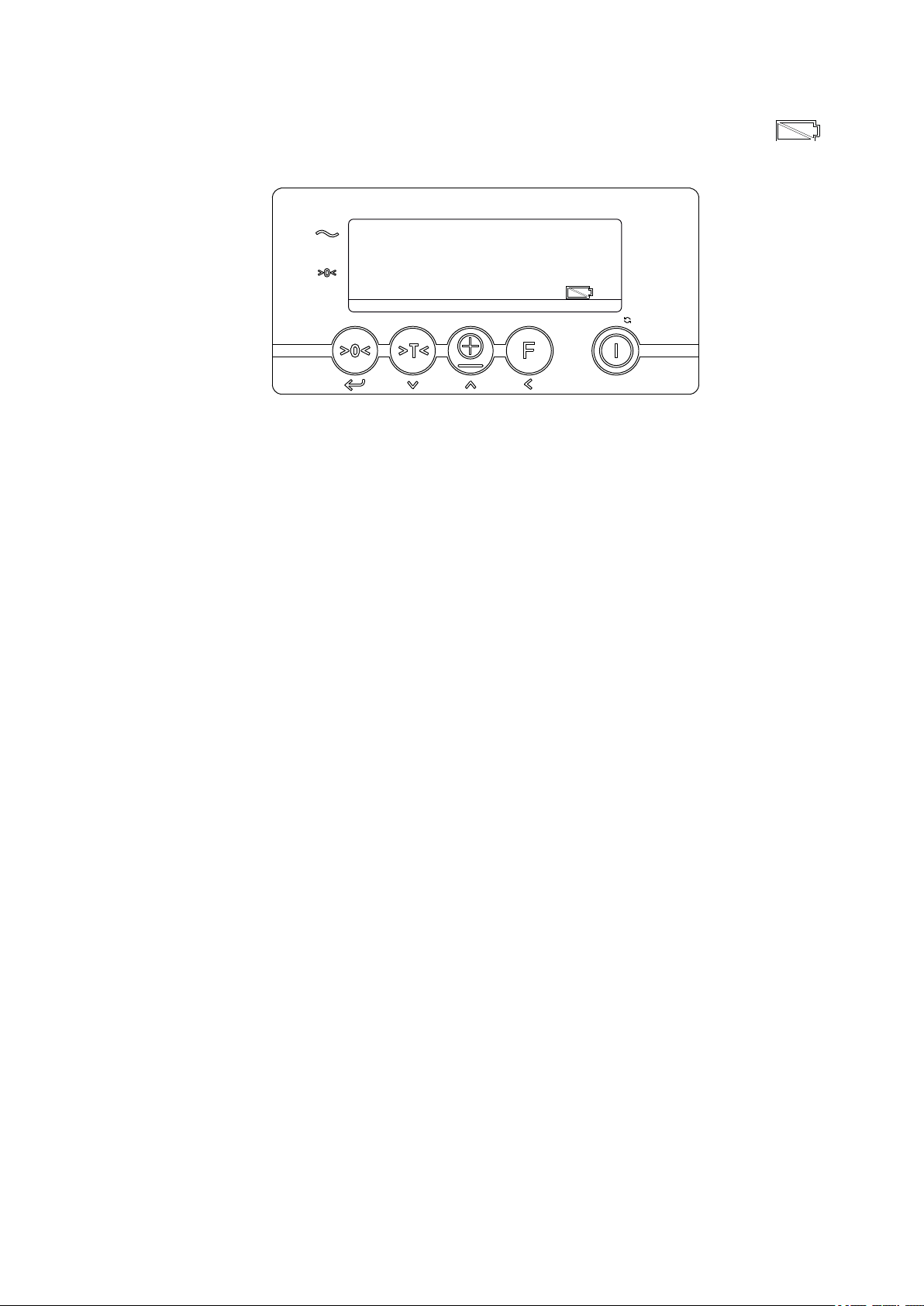
5.2 Battery charge status
NET
ID CODE PT TOTAL KG/LB
CLR
e1 e2 e3 STP1 STP2
Z
If the battery voltage is too low, the battery icon on the display lights
up. The weighing system switches off automatically after 2 minutes.
Checking the battery charge status
Procedure
• Check the display and, if necessary, charge the battery – see page 47.
46
11.19 en-GB
Page 47
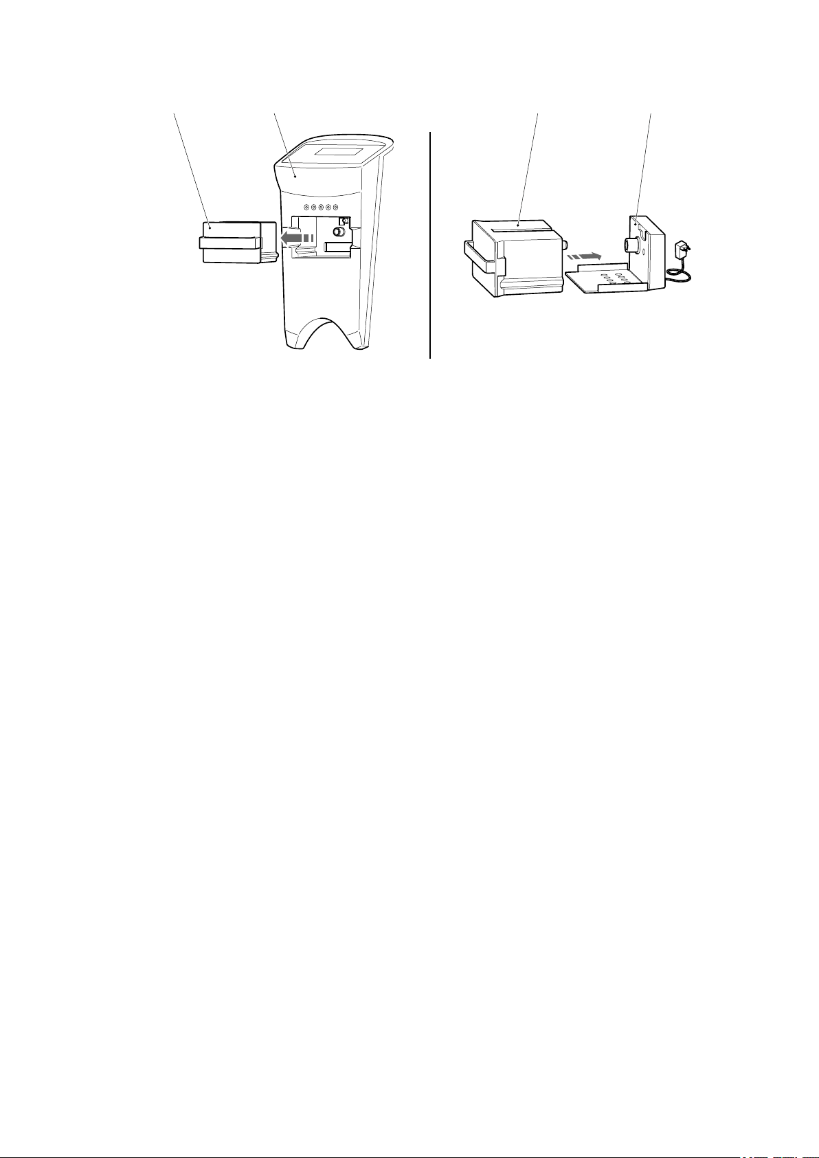
5.3 Charging the battery
3029 29 28
Charging the battery
Requirements
– Truck is parked securely.
– Weighing system is switched off – see page 79.
Tools and Material Required
– Charger for lithium-ion batteries (28)
Procedure
• Remove the battery (29) from the weighing system (30).
• Place the battery in the charger.
• Connect the charger to the power supply.
Z
Z
Z
The LED on the charger lights up red while charging is active.
• Disconnect the charger from the power supply once charging is completed.
The charger switches off and the LED lights up green once charging is completed.
A deep discharge of the battery can occur if it is not removed from a charger the
power supply of which has been interrupted.
• Place the battery in the weighing system.
The weighing system is ready for use again.
11.19 en-GB
47
Page 48

48
11.19 en-GB
Page 49

E Operation
1 Safety Regulations for the Operation of Forklift Trucks
Driver authorisation
The truck may only be used by suitably trained personnel, who have demonstrated
to the proprietor or his representative that they can drive and handle loads and have
been authorised to operate the truck by the proprietor or his representative.
Operator’s rights, responsibilities and rules of conduct
The driver must be informed of his duties and responsibilities and be instructed in
the operation of the truck and shall be familiar with the operating instructions. Safety
shoes must be worn on pedestrian-operated trucks.
Unauthorised use of truck
The operator is responsible for the truck during the time it is in use. The operator
must prevent unauthorised persons from moving or operating the truck. Do not carry
passengers or lift other people.
Damage and faults
The supervisor must be informed immediately of any damage or faults to the truck or
attachment. Trucks which are unsafe for operation (e.g. wheel or brake problems)
must not be used until they have been rectified.
Repairs
The operator must not carry out any repairs or alterations to the truck without
authorisation and the necessary training to do so. The operator must never disable
or adjust safety mechanisms or switches.
11.19 en-GB
49
Page 50

Hazardous area
WARNING!
Risk of accidents/injury in the hazardous area of the truck
A hazardous area is defined as the area in which people are at risk due to travel or
lifting operations of the truck, its load handler or the load. This also includes the area
within reach of falling loads or lowering/falling operating equipment.
Instruct unauthorised persons to leave the hazardous area.
u
In case of danger to third parties, give a warning signal in good time.
u
If unauthorised persons are still within the hazardous area, stop the truck
u
immediately.
Safety devices, warning signs and warning instructions
Safety devices, warning signs (see page 19) and warning instructions in the present
operating instructions must be strictly observed.
50
11.19 en-GB
Page 51

2 Displays and Controls
5
483
1
Item Control /display Function
1 Travel and parking brake
– Prevent the truck from rolling away.
o
– Decelerates the truck.
3 Handle
– To pull the truck.
t
– To push the truck.
4 “Lift//neutral/lower load
handler” handle
– In position "H" (lifting): Moving the tiller
t
raises the load handler.
– In position "neutral": Travel
– Press to position "S" (lowering): Lowers
the load handler.
5 Tiller
– Steers the truck.
t
– Raises the load handler.
8 Foot-activated parking
– Prevent the truck from rolling away.
o
brake
11.19 en-GB
51
Page 52

3 Starting up the truck
3.1 Checks and Operations to Be Performed Before Starting Daily Work
WARNING!
Damage and other truck or attachment (optional equipment) defects can result
in accidents.
If damage or other truck or attachment (optional equipment) defects are discovered
during the following checks, the truck must be taken out of service until it has been
repaired.
Report any defects immediately to your supervisor.
u
Mark defective truck and take out of service.
u
Do not return the industrial truck to service until you have identified and rectified
u
the fault.
Inspection before daily operation
Procedure
• Check the whole of the outside of the truck for signs of damage and leaks.
• Check the load handler for visible signs of damage such as cracks, bent or
severely worn forks.
• Check the load wheels for damage.
• Check that the markings and labels are present, clean and legible, see page 19.
• Test the brakes.
52
11.19 en-GB
Page 53

4 Industrial Truck Operation
4.1 Safety regulations for truck operation
Travel routes and work areas
Only use lanes and routes specifically designated for truck traffic. Unauthorised third
parties must stay away from work areas. Loads must only be stored in places
specially designated for this purpose.
The truck must only be operated in work areas with sufficient lighting to avoid danger
to personnel and materials. Additional equipment is necessary to operate the truck in
areas of insufficient lighting.
DANGER!
Do not exceed the permissible surface and point loading on the travel lanes.
At blind spots get a second person to assist.
The driver must ensure that the loading dock /dock leveller cannot be removed or
come loose during loading/unloading.
Conduct when pulling/pushing
The operator must adapt the travel speed to local conditions. The truck must be
pushed/pulled at slow speed when negotiating bends or narrow passageways, when
passing through swing doors and at blind spots. The operator must always observe
an adequate braking distance between the forklift truck and the vehicle in front and
must be in control of the truck at all times. Abrupt stopping (except in emergencies),
rapid U turns and overtaking at dangerous or blind spots are not permitted. Do not
lean out or reach beyond the working and operating area.
Visibility when pulling/pushing
The operator must look in the direction of travel and must always have a clear view
of the route ahead. If the truck is carrying loads that affect visibility, the truck must be
pulled against the load direction. If this is not possible, a second person must walk
alongside the truck as a lookout to observe the travel route while maintaining eye
contact with the operator. Move the truck only at walking pace and with particular
care. Stop the truck as soon as you lose eye contact.
11.19 en-GB
53
Page 54

Negotiating slopes and inclines
WARNING!
Do not negotiate slopes or inclines.
Negotiating lifts and dock levellers
Lifts may only be negotiated if they have sufficient capacity, are suitable for driving
on and authorised for truck traffic by the owner. The driver must satisfy himself of the
above before entering these areas. The truck must be pushed into lifts with the load
in front and must take up a position which does not allow it to come into contact with
the walls of the lift shaft. Persons riding in the lift with the forklift truck must only
enter the lift after the truck has come to a rest and must leave the lift before the
truck.
4.2 Parking the truck securely
WARNING!
An unsecured truck can cause accidents
Always park the truck on a level surface. In special cases the truck may need to be
u
secured with wedges.
Always fully lower the load handler.
u
Select a place to park where no other people are at risk of injury from the lowered
u
load handler.
54
11.19 en-GB
Page 55

4.3 Pushing/Pulling
153
8
Z
To avoid abrasion and wear, travelling without load should be with the load handler
raised.
Requirements
– Start up the truck, see page 52.
Procedure
• Release the parking brake by applying the footactivated parking brake (8, o) or the travel and
parking brake (1, o).
Using the handle (3) on the tiller (5), the truck can be
pushed or pulled in the required direction.
4.4 Steering
Procedure
• Swing the tiller (5) to the left or right.
Z
In tight bends the tiller extends beyond the truck geometry.
11.19 en-GB
55
Page 56

4.5 Brakes
153
8
8
The truck's braking characteristics depend largely on the surface condition of the
lanes. The driver must take this into account when travelling.
Manual braking
Procedure
• Pull or push against the direction of movement.
The truck brakes.
Braking with the foot-activated parking brake
(
o
)
Procedure
• Apply the foot-activated parking brake (8) in
direction B.
The truck brakes.
Braking with the travel and parking brake (o)
Procedure
• Applying the travel and parking brake (1).
The truck brakes.
11.19 en-GB
56
Page 57

4.6 Lifting, transporting and depositing loads
WARNING!
Unsecured and incorrectly positioned loads can cause accidents
Before lifting a load, the operator must make sure that it has been correctly
palletised and does not exceed the truck’s capacity.
Instruct other people to move away from the hazardous area of the truck. Stop
u
using the truck if people do not vacate the hazardous area.
Only carry loads that have been correctly secured and positioned. Use suitable
u
precautions to prevent parts of the load from tipping or falling down.
Damaged loads must not be transported.
u
Never exceed the maximum loads specified on the load chart.
u
Never stand underneath a raised load handler.
u
Do not stand on the load handler.
u
Do not lift other people on the load handler.
u
Insert the load handler as far as possible underneath the load.
u
NOTICE
Adapt a slower speed when stacking and retrieving.
11.19 en-GB
57
Page 58

4.6.1 Raising a load
H
4
5
1000
kg
1000
kg
Requirements
– Load correctly palletised.
– Load weight matches the truck's capacity.
– Load handler evenly loaded for heavy loads.
Z
In the case of eccentric loading, the forks are
slightly bent and twisted, which leads to variations
in the weighing results. In the case of inclinations
greater than 2°, holes and unevenness in the floor,
the accuracy of the weighing system decreases by
approx. 0.1% per degree.
Precise weighing results are obtained only when
the load centre is between the forks. A smooth flat
floor is required to ensure optimum weighing
accuracy.
Calibrated weighing system (o) (only AMW 22p
and AMW 22ps):
In the case of eccentric loading or inclinations
greater than 2°, the display is blocked. The truck
must be centrally loaded and standing on level
ground.
Procedure
• Drive the truck slowly up to the pallet.
• Push the handle (4) in the "H" direction.
• Slowly insert the load handler into the pallet until the
fork shank touches the pallet.
Z
Z
The load must not extend more than 50 mm beyond the
fork tips.
• Lift the load handler by moving the tiller (5) up and
down until you reach the desired lift height.
With rapid lift (up to 120 kg load, (t)), tiller movements
generate significantly greater lift movements.
11.19 en-GB
58
Page 59

4.6.2 Transporting a load
4
Requirements
– Load raised correctly.
– Good ground conditions.
Procedure
• Adapt your travel speed to the conditions of the route and the load you are
transporting.
• Move truck at a constant speed.
• Watch out for other traffic at crossings and passageways.
• Always move the truck with a lookout at blind spots.
WARNING!
Do not negotiate slopes or inclines.
4.6.3 Depositing a load
NOTICE
Loads must not be deposited on travel or escape routes, in front of safety
mechanisms or operating equipment that must be accessible at all times.
Requirements
– Storage location suitable for storing the load.
Procedure
• Drive the truck carefully up to the storage location.
• Push the handle (4) in direction S (lower) to lower the
load handler.
Z
Do not set the load down abruptly in order to avoid
damaging the load and the load handler.
• Carefully remove the load handler from the pallet.
The load has been set down.
11.19 en-GB
59
Page 60

4.7
33343132353637
38
AMW 22 / AMW 22p Standard Weigher (t)
4.7.1 Display and Controls
Z
Item Indicator Meaning
31 – Weight display in kg, messages
32 - – The displayed weight has a negative value.
33 (~) – The weighing system including the load is stable.
34 (NET) – The displayed weight is a net weight.
Only if the load is stable and the "Stable load" segment (33) is activated will key
commands be accepted and functions executed.
Item Operating function key Input function key
35 Zero setting,
– Confirm, Skip to next
Automatic tare
36 Enter tare weight – Reduce the value
37 Add a weight – Increase value.
38 On / Off – Adjustment
11.19 en-GB
60
Page 61

4.7.2 Display Messages
HELP 1 The weighing system has been overloaded.
NOTICE
The weight to be weighed exceeds the maximum setting. To avoid damage,
immediately relieve the weighing system of the load.
HELP 2 Negative signal from the load cells to the AD converter / inclination.
HELP 3 Negative signal from the load cells to the AD converter / inclination.
HELP 4 The tare weight entered is too high.
Z
Press key (36) to clear the display message. Enter a lower tare weight.
HELP 7 The signal from the load cells to the AD converter is too high.
LOW BAT The charge status is too low. The batteries must be replaced (AMW
22). The battery module must be charged (AMW 22p).
11.19 en-GB
61
Page 62

4.7.3 Operation
33343132353637
38
Z
After the load is raised, the display shows the gross value of the weighed weight.
Before each weighing operation, make sure that the system is unloaded and is free
to move. The weighing system has an automatic zero correction and automatically
compensates for small variations in the zero point. For larger variations in the zero
point, the correction must be performed manually using the 0/T key (35).
The weighing system offers the facility to make manual allowances for tare weights
and to track changes in the net weight:
Z
Procedure
• Raise the load.
• Press the 0/T key (35). The display indicates zero. The NET segment (31) shows
the activated tare weight.
• Loading or unloading the net load.
The net value of the weighed weight is displayed. On unloading, the a negative value
is shown for the net weight.
Performing a zero correction in the unloaded condition causes the system to return
to the standard weighing mode. A tare weight can be entered manually, in either the
loaded or unloaded condition. Tare weights higher than the first weight range (in the
standard version up to 200 kg) will not be accepted and will lead to the display
message HELP 4.
Checking the current tare weight:
Procedure
• Press the ENTER key (36). The most recently used tare value will appear. The
segment on the right side will flash.
• To continue to use the displayed value, keep the Confirm key (35) pressed for
three seconds.
To input a new tare weight:
11.19 en-GB
62
Page 63

Procedure
• Press the ENTER key (36).
• Press the Increase value key (37) or Decrease value key (36) to change the tare
weight. Press the Skip (35) to skip to the next field. Repeat this operation until the
desired value is displayed.
Activate or save the tare weight:
Procedure
• To confirm the value, keep the Confirm key (35) pressed for three seconds.
The tare weight is now activated (NET segment (31) active). If at this time the
system is laden, the net value for the weighed weight will appear in the display. If
at this time the system is unloaded, the display will show the entered tare weight
as a negative value.
Z
Z
The entered value will remain active until the weighing system is switched off, a new
tare weight is entered, a new load is tared or a new zero setting is performed.
Activate and save the tare weight:
Procedure
• Confirm all segments by pressing the Confirm key (35). The tare weight is now
activated (NET segment (34) active) and is saved. If at this time the system is
laden, the net value for the weighed weight will appear in the display. If at this time
the system is unloaded, the display will show the entered tare weight as a
negative value.
The entered value will remain active even after the system is switched off, until a
new tare weight is entered, a new load is tared or a new zero setting is performed.
Deactivating the tare weight by performing a Zeroing:
Procedure
• If the weighing system is loaded: Keep the PT key (36) pressed for two seconds.
The tare weight is reset. The system reverts to standard weighing mode.
• If the weighing system is unladen: Press the 0/T key (35).
A zero correction will be performed. The system reverts to standard weighing
mode.
11.19 en-GB
63
Page 64

33343132353637
38
Addition of individual weighings:
Procedure
• Load the system with the load to be added.
• Press the (37) key to add the weighed weight to the saved total weight.
The display shows the number of weighings recorded alternating with the total
weight. If the system is fitted with a built-in printer (o), the displayed value will be
printed out. After a few seconds the system reverts to standard weighing mode.
Z
If a tare weight is active, the net weights will be totalled.
To display the total weight:
Procedure
• Keep key (37) pressed for three seconds; the total weight calculated thus far will
be displayed.
The display shows the current number of weighings alternating with the total
weight. After a few seconds the system reverts to standard weighing mode.
Resetting the total of individual weighings:
Procedure
• Press the (37) key whilst the total weight is being displayed.
If the system is fitted with a built-in printer (o), a cumulative printout is performed
before the total is reset.
After resetting, the display shows the number of weighings recorded as 00 and
the starting value for the total weight as 0 kg (AMW 22) or 0.0 kg (AMW 22p).
After a few seconds the system reverts to standard weighing mode.
Printing (o)
11.19 en-GB
64
Page 65

Z
A gross weight will be identified on the printout by "B/G", a net weight by "N". If a tare
weight has been input, this will also be printed out and identified by "PT". The total
net weight is identified by "TOT" (Total).
Example of a printout:
01 B/G 6.8 kg
02 B/G 158.2 kg
03 N 426.5 kg
04 N 1200.0 kg
04 PT 150.0 kg
04 TOT 1791.5 kg
11.19 en-GB
65
Page 66

4.8
443940414243464547
4849505152
53
AMW 22p Weigher, Special Version (o)
4.8.1 Display and Controls
Z
Item Indicator Meaning
39 - – The displayed weight has a negative value.
40 (e1) – The displayed weight lies in weight range 1.
41 (e2) – The displayed weight lies in weight range 2.
42 (e3) – The displayed weight lies in weight range 3.
43 (Stp1) – The limit value 1 is activated.
44 (Stp1) – The limit value 2 is activated.
45 – Weight display in kg or lb, messages, quantities
46 (~) – The weighing system including the load is stable.
47 (ZERO) – The displayed weight is within the zero range.
48 (NET) – The displayed weight is a net weight.
Only if the load is stable and the "Stable load" segment (46) is activated will key
commands be accepted and functions executed.
11.19 en-GB
66
Page 67

Item Operating function
level 1
(Press key briefly)
49 Zero offset – Input the code – Confirm
50 Tare the weight – Enter tare weight – Reduce the value
Operating function
level 2
(Press key for a longer
time)
Input function
press the
51 Print out the weight and
total it
52 Calculate piece weight
Relay control (o)
53 On / Off – Change over units of
4.8.2 Display Messages
Err01 Weighing cell signal not stable.
Err02 The weighing system has been overloaded.
NOTICE
The measured weight exceeds the maximum setting. To avoid damage, remove the
load from the weighing system immediately.
Err03 Negative gross weight. This action is not permitted.
Err04 Outside zero range. Acknowledge with any key.
Err05 Accuracy of the piece calculation too low. Acknowledge with any key.
– Check subtotal, print
out final total
– Input the piece weight – Skip to next, activate
measure
– Increase value.
the value
– Adjustment
Z
Err06 Load cell signal too high. Automatic for correction of the input.
Err07 Load cell signal too low. Automatic for correction of the input.
Err08 Calibration out of range (negative).
Err09 Calibration out of range (signal too low).
Err10 Calibration value of point 2 or 3 lower than point 1 or 2.
Err11 Calibration from piece counting mode
Err14 Limit value 2 < limit value 1 (not permitted)
Err97 Calibration blocked (jumper JP1 present)
Err98 The calibration value must be higher than the previous one.
Err99 Confirmation only permitted on power-up unit.
LOW BAT The charge status is too low. The battery module must be charged.
The following additional messages may appear on the display and printout:
Err00 Error message
AddEd Addition confirmation
Add10 Add quantity
11.19 en-GB
Adj08 Adjustment value display
TarE Tare setting of metering operation performed
67
Page 68

DonE Confirmation of metering operation performed
443940414243464547
4849505152
53
PA 00 Parameter number display
StoP Metering operation aborted
ho 00 Hour setting display
m 00 Minute setting display
dA 00 Day setting display
m 00 Month setting display
yE 00 Year setting display
4.8.3 Operation
Z
After the load is raised, the display shows the gross value of the weighed weight.
Before each weighing operation, make sure that the system is unloaded and is free
to move. The weighing system has an automatic zero correction and automatically
compensates for small variations in the zero point. For larger variations in the zero
point, the correction must be performed manually using the >0< key (49).
The weighing system offers the facility to make manual allowances for tare weights
and to track changes in the net weight:
Procedure
• Lift the load.
• Press the T key (50). The display indicates zero. The NET segment (31) shows
the activated tare weight.
• Loading or unloading the net load.
11.19 en-GB
68
Page 69

Z
The net value of the weighed weight is displayed. On unloading, the a negative value
is shown for the net weight.
Press the T key (50) to read off the gross weight. The NET segment (48) is
deactivated. Press the T key (50) again to perform a new net weighing.
A tare weight can be entered manually, in either the loaded or unloaded condition.
The tare weight is input at high resolution, irrespective of weight range and value. A
tare weight that is greater than the capacity of the weighing system will not be
accepted.
Checking the current tare weight:
Procedure
• Keep the PT key (50) pressed for three seconds. The most recently used tare
value will appear. The segment on the right side will flash.
• Press Confirm (49) to continue to use the displayed value.
To input a new tare weight:
Procedure
• Keep the PT key (50) pressed for three seconds.
• Press the Increase value key (51) or Decrease value key (50) to change the tare
weight. Press the Skip (52) to skip to the next field. Repeat this operation until the
desired value is displayed.
Z
Z
Activate or save the tare weight:
Procedure
• Press the Confirm key (49) to confirm the value.
The tare weight is now activated (NET segment (48) active). If at this time the
system is laden, the net value for the weighed weight will appear in the display. If
at this time the system is unloaded, the display will show the entered tare weight
as a negative value.
The value that is input will remain active until a new tare weight is entered.
Press the T key (50) to read off the gross weight.
Checking the identity code number:
The weighing system offers the facility to assign identity code numbers to weighings,
to identify them for subsequent processing. These identity code numbers may be up
to five digits long.
Procedure
• Keep the No key (49) pressed for three seconds.
The identity code number most recently input will be displayed. The last position
on the right of the display will flash.
• Press Confirm (49) to continue to use the displayed value.
Z
11.19 en-GB
The identity code number will be accepted. The weighing system reverts to weighing
mode.
69
Page 70

Inputting a new identity code number:
Procedure
• Keep the No key (49) pressed for three seconds. The identity code number most
recently input will be displayed. The last position on the right of the display will
flash.
• Press the Increase value key (51) or Decrease value key (50) to change the
identity code number . Press the Skip (52) to skip to the next field.
Repeat this operation until the desired value is displayed.
• Press Confirm (49) to load the displayed value.
The identity code number will be accepted. The weighing system reverts to
weighing mode.
Z
Z
The identity code number "00000" is not reported separately on the print-out.
Piece Counting by Calculating the Piece Weights
Pieces can be counted using a known or weighed piece weight. Larger differences in
weight and larger quantities for determining the piece weight result in more accurate
piece weights. The piece weight and the calculated quantity of pieces can be printed
out.
The difference in weight for calculating the piece weight should not be less than 4 to
5 kg.
Piece counting over a piece weight to be weighed, preset to 10 pieces:
Procedure
• Press the piece weight key (52).
The message “Add10“ is displayed. The unit displayed changes from "kg" to
"pcs".
• Increasing or reducing the number of goods placed on the load handler by 10
pieces.
• Press the Confirm key (49).
The calculation of the piece weight will be performed. The quantity of pieces
determined by the weighing will be displayed.
70
11.19 en-GB
Page 71

443940414243464547
4849505152
53
Piece counting over a piece weight to be weighed, with a different quantity of
pieces:
Procedure
• Press the piece weight key (52).
The message “Add10“ is displayed. The unit displayed changes from "kg" to
"pcs".
• Press the Increase value key (51) or Decrease value key (50) to change the
quantity of pieces to a maximum of 95 pieces.
Z
If the accuracy of the piece weight that was determined is too low, the display
message "Err05" appears. Press any key to acknowledge and to increase the
quantity of pieces.
• Increasing or reducing the number of goods placed on the load handler by the
number of pieces entered.
• Press the Confirm key (49).
The calculation of the piece weight will be performed. The quantity of pieces
determined by the weighing will be displayed.
Counting the pieces over the piece weight that was entered:
Procedure
• Keep the Input Piece Weight key (52) pressed for three seconds.
The most recently input piece weight will be displayed. The last position on the
right of the display will flash.
• Press Confirm (49) to load the displayed value.
The quantity of pieces determined by the weighing will be displayed.
To input a new tare piece weight:
11.19 en-GB
71
Page 72

Procedure
443940414243464547
4849505152
53
• Keep the Input Piece Weight key (52) pressed for three seconds.
The most recently input piece weight will be displayed. The last position on the
right of the display will flash.
• Press the Increase value key (51) or Decrease value key (50) to change the piece
weight. Press the Skip (52) to skip to the next field.
Repeat this operation until the desired value is displayed.
• Press Confirm (49) to load the displayed value.
The quantity of pieces determined by the weighing will be displayed.
End the piece counting to revert to standard weighing mode:
Procedure
• Keep the Change Over key (53) pressed for three seconds.
The system reverts to standard weighing mode. The quantity of pieces that was
determined is cleared down.
Addition of individual weighings:
Procedure
• Load the system with the load to be added.
• Press the ± key (51) to add the weighed weight to the saved total weight.
The gross, net and tare weights will be added. The weight summation is
confirmed with the display message "Added". The system reverts to standard
weighing mode. If the system is fitted with a built-in printer (o), the displayed value
will be printed out.
Z
No weight can be added twice. The system must be brought into the zero range
before a second weight can be added.
To display the total weight:
11.19 en-GB
72
Page 73

Procedure
• Keep key (51) pressed for three seconds; the total weight calculated thus far will
be displayed.
Z
The display shows the current number of weighings alternating with the total weight
on a three second cycle. If no key is pressed whilst this display is being shown, the
system reverts to standard weighing mode after 60 seconds. The current total weight
is retained in the memory.
Resetting the total of individual weighings, with print-out:
Procedure
• Press key (51) for three seconds whilst the total weight is being displayed.
The total weight will be reset. A cumulative printout is performed before the total is
reset.
Resetting the total of individual weighings, without print-out:
Procedure
• Press the On/Off key (53) whilst the total weight is being displayed.
The total weight will be reset.
Switching the unit of weight display between "kg" and "lb":
Z
Procedure
• Keep the Change Over key (53) pressed for three seconds.
The current weight will be displayed for 5 seconds in the second unit of weight.
The display switches automatically back into the preset start unit of weight.
Whilst the display is showing weights in the change-over unit of weight, the weighing
functions cannot be performed: If any key is pressed, the display message "Err99"
appears. The system reverts to standard weighing mode.
11.19 en-GB
73
Page 74

Printing (o)
Z
A gross weight will be identified on the printout by "B/G", a net weight by "N". If a tare
weight has been input, this will also be printed out and identified by "PT". The total
net weight is identified by "TOT" (Total).
Example of printout of a weighing:
without identity code number with identity code number
B/G 1234.5 kg CODE 12345
T 34.5 kg B/G 1234.5 kg
N 1200.5 kg T 34.5 kg
N 1200.5 kg
No. 1
10/07/03 17:45 No. 1
10/07/03 17:45
Example of a printout of a piece counting:
without identity code number with identity code number
B/G 1234.5 kg CODE 12345
T 34.5 kg B/G 1234.5 kg
N 1200.5 kg T 34.5 kg
N 1200.5 kg
PcWt 1234.5 kg
Qty 1234 PCs PcWt 1234.5 kg
Qty 1234 PCs
No. 1
10/07/03 17:45 No. 1
10/07/03 17:45
Example of a printout of a total weight (also without identity code number):
Tot. B/G 1234.5 kg
Tot. T 34.5 kg
Tot. N 1200.5 kg
74
Tot. No. 999
10/07/03 17:45
11.19 en-GB
Page 75

443940414243464547
4849505152
53
Check the time:
Procedure
• Keep the (52) key pressed for six seconds.
The display shows the message "ho 00" or the last hours setting.
• Press Confirm (49) to load the displayed value.
Setting the date and time:
Procedure
• Keep the (52) key pressed for six seconds.
The display shows the message "ho 00" or the last hours setting. The last position
on the right of the display will flash.
• Press the Increase value key (51) or Decrease value key (50) to change the
position that is flashing. Press the Skip (52) to skip to the next field.
• Press Confirm (49) to load the displayed value.
• The display shows the message "m 00" or the last minutes setting.
The change procedure is as above.
Press Confirm (49) to load the displayed value.
• The display shows the message "m 00" or the last month setting.
The change procedure is as above.
Press Confirm (49) to load the displayed value.
• The display shows the message "YE 00" or the last year setting.
The change procedure is as above.
Press Confirm (49) to load the displayed value.
The system reverts to standard weighing mode.
11.19 en-GB
75
Page 76

4.9 AMW 22ps weighing system
NET
ID CODE PT TOTAL KG/LB
CLR
e1 e2 e3 STP1 STP2
kg
lb
4.9.1 Display and Controls
The items shown in the display have the following meaning:
Symbol Display Meaning
The weighing system including the load is stable.
The displayed weight is negative.
>0< The displayed weight is within the zero range.
NET The display is showing the net weight.
e1 The displayed weight is within range 1
(multi-range option – see page 14).
e2 The displayed weight is within range 2
(multi-range option – see page 14).
e3 The displayed weight is within range 2
(multi-range option – see page 14).
STP1 Limit value 1 is activated
(function key option activated).
STP2 Limit value 2 is activated
(function key option activated).
kg The weight is displayed in kilogrammes (kg).
lb The weight is displayed in pounds (lb).
The weighing system battery must be charged.
76
11.19 en-GB
Page 77

Key functions
ID CODE
ID CODE
PT
TOTAL
KG/LB
CLR
Z
Each key has three functions. In the weighing system description, the keys are
named according to their individual function.
Example
Function Displayed location Example
Additional function
Above the key
ID CODE
(long key press)
Standard function
On the key >0<
(short key press)
Input function
Below the key Enter
(in input mode)
Key functions
Key Function Description
Additional function Code entry
Standard function Zero setting
Input function Enter
Z
Additional function Enter a known tare value
Standard function Automatic tare
Input function Reduce the value of a flashing digit
Additional function Display an intermediate result and print out the
total weight
Standard function Print out the weighing data and sum the
individual weights to form the total weight
Input function Increase the value of a flashing digit
Additional function No function
Standard function Start the special function (when active)
Input function Move left to the next digit
Additional function Switch between [kg] and [lb]
Activate and deactivateStandard function
Delete the entryInput function
The functions are only executed if the load is stable and the arrow next to the
symbol is displayed – see page 76.
11.19 en-GB
77
Page 78

4.9.2 Display Messages
Display Meaning Corrective measures
Err01 Load cell signal is not stable Automatic
Err02 Capacity of the weighing system
exceeded
Err03 Gross weight is negative.
This is not permitted.
Err04 Outside the zero range Press any key
Err06 Input signal too high Automatic after adjustment of input
Err08 Adjustment outside of range
(negative)
Err09 Adjustment outside of range (signal
too low)
Err10 Adjustment value 2 (3) is lower
than value 1 (2)
Err14 Switching value 2 < switching value
1
This is not permitted.
CAL-J Calibrated version only
No action permitted
Automatic after load has been
removed
Automatic
signal
Automatic
Automatic
Automatic
Automatic
If no action is required, remove
jumper JP1.
Z
Err98 Adjustment point must be higher
than the previous one
Err99 Operation only permitted on power-
up unit
---- Load cell signal is negative Raise load handler
Err_L Truck is not level
(calibrated version only)
Weighing system battery is empty Charge the battery
OimL Action not permitted
(calibrated version only)
ntEP Action not permitted
(calibrated version only)
SCALL Test path number outside of range Contact service
Automatic
Automatic
Level the truck
Automatic
Automatic
Following this action, a
complete reconfiguration
and recalibration of the
system is required.
78
ESoFt Incorrect firmware combination Contact service
EConF P96 not set Set P96 according to the used
hardware
11.19 en-GB
Page 79

4.9.3 Operation
KG/LB
CLR
NET
ID CODE PT TOTAL KG/LB
CLR
e1 e2 e3 STP1 STP2
kg
KG/LB
CLR
NET
ID CODE PT TOTAL KG/LB
CLR
e1 e2 e3 STP1 STP2
ID CODE
NET
ID CODE PT TOTAL KG/LB
CLR
e1 e2 e3 STP1 STP2
kg
4.9.3.1 Activating and deactivating the weighing system
Activating the weighing system Key Display
– Briefly press the "activate" key.
Z
The weighing system is ready
for use after 5 seconds.
Deactivating the weighing system Key Display
– Press the "deactivate" key for
approx. 3 seconds.
Z
The display switches to OFF.
4.9.3.2 Checking the zero point
Z
Before each weighing operation, ensure that there is no load on the system and that
it is unoccupied. The weighing system features automatic zero adjustment. This
means that small deviations of the zero point are corrected automatically. If the zero
point is not corrected automatically, a manual adjustment can be performed.
Correcting the zero point Key Display
– Briefly press the ">0<" key.
Z
The zero point is corrected.
In the display, the arrow next
to ">0<" indicates that the
zero point has been adjusted.
11.19 en-GB
79
Page 80

4.9.3.3 Automatic shutdown of the weighing system
NET
ID CODE PT TOTAL KG/LB
CLR
e1 e2 e3 STP1 STP2
kg
NET
ID CODE PT TOTAL KG/LB
CLR
e1 e2 e3 STP1 STP2
NET
ID CODE PT TOTAL KG/LB
CLR
e1 e2 e3 STP1 STP2
kg
The weighing system shuts down automatically after approx. 20 minutes without
user input.
Interrupting automatic shutdown Key Display
Z
The shutdown process is
indicated for 20 seconds.
Z
Once all five sections in the
display have been filled, the
weighing system switches off.
– Press any key to return to
weighing mode.
Z
The weighing system reverts
to weighing mode.
80
11.19 en-GB
Page 81

4.9.3.4 Net weighing with automatic tare determination
NET
ID CODE PT TOTAL KG/LB
CLR
e1 e2 e3 STP1 STP2
kg
PT
NET
ID CODE PT TOTAL KG/LB
CLR
e1 e2 e3 STP1 STP2
kg
NET
ID CODE PT TOTAL KG/LB
CLR
e1 e2 e3 STP1 STP2
kg
PT
NET
ID CODE PT TOTAL KG/LB
CLR
e1 e2 e3 STP1 STP2
kg
Example
– Weight of the pallet: 25 kg
– Weight of the load: 1000 kg
Net weighing process Key Display (example)
– Pick up and raise the pallet.
Z
The weight of the pallet is
shown on the display.
– Briefly press the "> T<" key.
Z
The weight display is reset to
zero. The "NET" display
indicates that the tare weight
is active.
– Deposit the load on the pallet.
Z
The display shows the net
value of the measured weight.
Z
– To display the gross weight, press
the ">T<" key again.
Z
The display shows the gross
weight (pallet plus load). The
"NET" display disappears.
On a weighing system certified by OIML (Organisation Internationale de Métrologie
Légale), the tare value is deleted automatically when the weight returns to zero. The
tare function must be reactivated for the next weighing operation.
11.19 en-GB
81
Page 82

4.9.3.5 Net weighing with manual tare entry
NET
ID CODE PT TOTAL KG/LB
CLR
e1 e2 e3 STP1 STP2
kg
PT
NET
ID CODE PT TOTAL KG/LB
CLR
e1 e2 e3 STP1 STP2
TOTAL
NET
ID CODE PT TOTAL KG/LB
CLR
e1 e2 e3 STP1 STP2
NET
ID CODE PT TOTAL KG/LB
CLR
e1 e2 e3 STP1 STP2
Example
– Weight of the pallet: 25 kg
– Weight of the load: 1000 kg
Tare entry and net weighing
process
– Pick up and raise the pallet with
the load.
Z
The weight of the pallet and
the load is shown on the
display.
– Press the "PT" key for approx.
3 seconds.
Z
The display switches to
"00000" and the last zero
flashes.
– Press the "up" arrow key until the
flashing digit has the desired
value.
Z
In this example, the arrow key
must be pressed 5 times.
Key Display (example)
– To switch to the next digit, press
the "left" arrow key.
Z
The flashing display switches
to the next digit.
82
11.19 en-GB
Page 83

Tare entry and net weighing
TOTAL
NET
ID CODE PT TOTAL KG/LB
CLR
e1 e2 e3 STP1 STP2
ID CODE
NET
ID CODE PT TOTAL KG/LB
CLR
e1 e2 e3 STP1 STP2
kg
NET
ID CODE PT TOTAL KG/LB
CLR
e1 e2 e3 STP1 STP2
kg
NET
ID CODE PT TOTAL KG/LB
CLR
e1 e2 e3 STP1 STP2
kg
PT
ID CODE
process
– Press the "up" arrow key until the
flashing digit has the desired
value.
Key Display (example)
Z
In this example, the arrow key
must be pressed 2 times.
– Press the "Enter" key to confirm
your input.
Z
The net weight is displayed.
The "NET" display indicates
that the tare weight is active.
Remove the load.
Z
The display switches to zero.
Set down the pallet.
Z
The display shows a negative
value.
Z
On a weighing system certified by OIML (Organisation Internationale de Métrologie
Légale), the tare value is deleted automatically when the weight returns to zero. The
tare function must be reactivated for the next weighing operation.
Z
11.19 en-GB
The last manual tare value to be used is stored in the tare memory.
To access the tare memory, press the "PT" key for approx. 3 seconds.
Then press the "Enter" key.
83
Page 84

4.9.3.6 Summing individual weights and deleting the totals memory
NET
ID CODE PT TOTAL KG/LB
CLR
e1 e2 e3 STP1 STP2
kg
TOTAL
NET
ID CODE PT TOTAL KG/LB
CLR
e1 e2 e3 STP1 STP2
NET
ID CODE PT TOTAL KG/LB
CLR
e1 e2 e3 STP1 STP2
kg
NET
ID CODE PT TOTAL KG/LB
CLR
e1 e2 e3 STP1 STP2
kg
TOTAL
NET
ID CODE PT TOTAL KG/LB
CLR
e1 e2 e3 STP1 STP2
NET
ID CODE PT TOTAL KG/LB
CLR
e1 e2 e3 STP1 STP2
kg
Example
– Weight of load no. 1: 250 kg
– Weight of load no. 2: 1250 kg
Summing individual weights Key Display (example)
– Pick up and raise the pallet.
– Activate tare – see page 81 or
see page 82.
– Deposit load no. 1 on the pallet.
Z
The weight of load no. 1 is
shown on the display.
– To add the weight to the total
weight, press the "+" key.
Z
The display switches back
and forth between the number
of weighing operations and
the weight of the load 3 times.
The display then
automatically reverts to
weighing mode.
Z
If a printer is connected, a
printout is created with the
gross, tare and net weights.
– Remove load no. 1 from the
pallet.
– Deposit load no. 2 on the pallet.
Z
The weight of load no. 2 is
shown on the display.
– To add the measured weight to
the total weight, press the "+" key.
Z
The display switches back
and forth between the number
of weighing operations and
the total weight 3 times.
The display then
automatically reverts to
weighing mode.
Z
If a printer is connected, a
printout is created with the
gross, tare and net weights.
84
11.19 en-GB
Page 85

Displaying the intermediate result Key Display (example)
TOTAL
NET
ID CODE PT TOTAL KG/LB
CLR
e1 e2 e3 STP1 STP2
kg
TOTAL
NET
ID CODE PT TOTAL KG/LB
CLR
e1 e2 e3 STP1 STP2
NET
ID CODE PT TOTAL KG/LB
CLR
e1 e2 e3 STP1 STP2
kg
TOTAL
NET
ID CODE PT TOTAL KG/LB
CLR
e1 e2 e3 STP1 STP2
NET
ID CODE PT TOTAL KG/LB
CLR
e1 e2 e3 STP1 STP2
kg
KG/LB
CLR
– To check the intermediate result,
press the "Total" key for approx.
3 seconds.
Z
The current weight is shown
on the display.
Resetting the weighing data Key Display (example)
– To reset the weighing data, press
the "Total" key again for approx.
3 seconds.
Z
The display flashes while
switching back and forth
between the number of
weighing operations and the
weight.
Z
Z
There are two options for resetting the weighing data:
- Reset and print
- Reset
– To reset and print the weighing
data, press the "+" key.
– To reset the weighing data, press
the "CLR" key.
If the total is not used manually or reset, this is done automatically by the system
once the maximum of 99 storage locations has been exceeded or the total weight
has reached a value of 99,999 kg.
11.19 en-GB
85
Page 86

4.9.3.7 Entering a code number
ID CODE
NET
ID CODE PT TOTAL KG/LB
CLR
e1 e2 e3 STP1 STP2
ID CODE
NET
ID CODE PT TOTAL KG/LB
CLR
e1 e2 e3 STP1 STP2
kg
NET
ID CODE PT TOTAL KG/LB
CLR
e1 e2 e3 STP1 STP2
NET
ID CODE PT TOTAL KG/LB
CLR
e1 e2 e3 STP1 STP2
TOTAL
PT
ID CODE
NET
ID CODE PT TOTAL KG/LB
CLR
e1 e2 e3 STP1 STP2
kg
A code number consisting of no more than five digits can be assigned to weighing
operations for easy identification during subsequent processing.
Example
– Last code number entered: 20500
– New code number: 20700
Displaying the code number Key Display (example)
– To display the last code number to
be entered, press the "ID code"
key for approx. 3 seconds.
Z
The most recently entered
code number is displayed.
The right digit flashes.
Confirming the code number Key Display
– To reuse the code number, press
the "Enter" key.
Z
The code number is
confirmed. The display
reverts to weighing mode.
Entering a code number Key Display (example)
– To change a different digit to the
one that is flashing, press the
"left" arrow key.
– To increase the value of the
flashing digit, press the "up" arrow
key.
– To reduce the value of the flashing
Z
– To confirm the new code number,
Z
86
digit, press the "down" arrow key.
The code number 00000 is
invalid and will not be printed.
press the "Enter" key.
The code number has been
changed. The display reverts
to weighing mode.
11.19 en-GB
Page 87

4.9.3.8 Printing weighing data
If the weighing system is equipped with a printer, current weighing data and entered
data can be printed. The date and time are only printed if the option has been
installed.
On the printout, the weights and corresponding data appear as follows:
Weight Label
Code number CODE
Gross weight [kg] or [lb] B/G
Net weight [kg] or [lb] N
Manually entered tare [kg] or [lb] PT
Total weight Tot.
Date format (year/month/day) YY/MM/DD
Time in 24h format (hours/minutes) HH:MM
Example 1:
Standard printout without
code number
Example 2:
Standard printout with code
number
CODE 12345
B/G 1234.5 kg B/G 1234.5 kg
T 34.5 kg T 34.5 kg
N 1200.0 kg N 1200.0 kg
No. 1 No. 1
19/07/03 17:45 19/07/03 17:45
Example 3:
Total weight (always without
code)
Tot. B/G 1234.5 kg
Tot. T 34.5 kg
Tot. N 1200.0 kg
No. 1
Tot. No. 999
11.19 en-GB
19/07/03 17:45
87
Page 88

4.9.3.9 Changing the unit of measure
NET
ID CODE PT TOTAL KG/LB
CLR
e1 e2 e3 STP1 STP2
kg
KG/LB
CLR
NET
ID CODE PT TOTAL KG/LB
CLR
e1 e2 e3 STP1 STP2
lb
The weighing system starts with the preset weight unit [kg] or [lb]. In weighing mode,
it is possible to switch between the units.
Example
– Preset weight unit: kg
Changing the unit of measure Key Display (example)
Z
The weight is displayed in the
preset weight unit.
– To change the unit of measure,
press the "KG/LB" key for approx.
3 seconds.
Z
The display switches to the
other weight unit for
5 seconds.
88
11.19 en-GB
Page 89

4.9.3.10 Changing the time and date on the printout
TOTAL
NET
ID CODE PT TOTAL KG/LB
CLR
e1 e2 e3 STP1 STP2
ID CODE
NET
ID CODE PT TOTAL KG/LB
CLR
e1 e2 e3 STP1 STP2
PT
TOTAL
NET
ID CODE PT TOTAL KG/LB
CLR
e1 e2 e3 STP1 STP2
ID CODE
NET
ID CODE PT TOTAL KG/LB
CLR
e1 e2 e3 STP1 STP2
PT
TOTAL
NET
ID CODE PT TOTAL KG/LB
CLR
e1 e2 e3 STP1 STP2
Setting the time and date Key Display (example)
– To access the user menu, press
the "Total" key for approx.
10 seconds.
Z
USER is shown on the
display.
– Press the "Enter" key to access
the sub-menu.
Z
The first menu entry is shown
on the display.
– Select TIME in the menu.
Z
You can use the arrow keys to
scroll through the user menu.
– Confirm your selection with the
"Enter" key.
Z
"ho_00" or the previous hour
setting is shown on the
display. The right digit
flashes.
Proceed as follows to set the hours:
– Adjust the flashing digit using the
"up" and "down" arrow keys.
– Switch to the next digit using the
"left" arrow key and set the digit to
the desired value.
11.19 en-GB
89
Page 90

Setting the time and date Key Display (example)
ID CODE
NET
ID CODE PT TOTAL KG/LB
CLR
e1 e2 e3 STP1 STP2
ID CODE
NET
ID CODE PT TOTAL KG/LB
CLR
e1 e2 e3 STP1 STP2
ID CODE
NET
ID CODE PT TOTAL KG/LB
CLR
e1 e2 e3 STP1 STP2
NET
ID CODE PT TOTAL KG/LB
CLR
e1 e2 e3 STP1 STP2
KG/LB
CLR
NET
ID CODE PT TOTAL KG/LB
CLR
e1 e2 e3 STP1 STP2
kg
– Press the "Enter" key to confirm
the new value.
Z
The display switches to the
minutes.
– Set the minutes in the same way
as the hours.
– Press the "Enter" key to confirm
the new value.
Z
The display switches to the
TIME menu entry.
– To exit the TIME menu, press the
"Enter" key for approx. 3 seconds.
Z
The display first switches to
the SET entry and then to the
USER menu.
– Briefly press the "CLR" key to
return to weighing mode.
Z
The weighing system reverts
to weighing mode.
90
11.19 en-GB
Page 91

4.9.3.11 Accessing user settings
TOTAL
NET
ID CODE PT TOTAL KG/LB
CLR
e1 e2 e3 STP1 STP2
ID CODE
PT
TOTAL
NET
ID CODE PT TOTAL KG/LB
CLR
e1 e2 e3 STP1 STP2
ID CODE
NET
ID CODE PT TOTAL KG/LB
CLR
e1 e2 e3 STP1 STP2
Opening the user menu Key Display (example)
– To access the user menu, press
the "Total" key for approx.
10 seconds.
Z
USER is shown on the
display.
– Press the "Enter" key to access
the menu entries.
Z
The first menu entry is shown
on the display.
Z
Explanations of the various
menu entries are provided on
the following pages.
– Use the arrow keys to access the
desired menu entry (in this case
SLEEP).
Z
The menu entries appear one
after the other on the display.
– Briefly press the "Enter" key to
select the displayed menu entry.
Menu entries:
– A_oFF
– dAtE
– tImE
– bLoFF
– LIght
– SLEEP
Z
Z
In this example, the preset
value "20" is displayed. The
right digit flashes.
In other menu entries, a
further menu may follow in
which you can select a value.
11.19 en-GB
91
Page 92

Changing settings, saving and
ID CODE
NET
ID CODE PT TOTAL KG/LB
CLR
e1 e2 e3 STP1 STP2
ID CODE
NET
ID CODE PT TOTAL KG/LB
CLR
e1 e2 e3 STP1 STP2
NET
ID CODE PT TOTAL KG/LB
CLR
e1 e2 e3 STP1 STP2
KG/LB
CLR
NET
ID CODE PT TOTAL KG/LB
CLR
e1 e2 e3 STP1 STP2
kg
NET
ID CODE PT TOTAL KG/LB
CLR
e1 e2 e3 STP1 STP2
ID CODE
NET
ID CODE PT TOTAL KG/LB
CLR
e1 e2 e3 STP1 STP2
kg
exiting the user menu
– Enter or select a value – for
procedure see page 89.
– Briefly press the "Enter" key to
confirm the new value.
Key Display (example)
Z
The display returns to the
menu entry (in this case
SLEEP).
– To return to the USER menu,
press the "Enter" key for approx.
3 seconds.
Z
The display first switches to
the SET entry and then to the
USER menu.
– Briefly press the "CLR" key to
return to weighing mode.
Z
The weighing system reverts
to weighing mode.
Exiting the user menu without
changes
Initial situation
– The display shows the menu entry
that you want to exit.
– Briefly press the "CLR" key to
return to weighing mode.
Z
The weighing system reverts
to weighing mode.
Key Display (example)
92
11.19 en-GB
Page 93

Menu entries and their meaning
e1 e2 e3 STP1 STP2
e1 e2 e3 STP1 STP2
e1 e2 e3 STP1 STP2
e1 e2 e3 STP1 STP2
e1 e2 e3 STP1 STP2
Function Set the automatic shutdown time in minutes
Comments A setting of "00" means that the display is always on.
This will result in increased power consumption.
Settings 00 - 99
Default 30
Function Set the date
Comments None
Settings da_xx / m_xx / YE_xx (day / month / year)
Default None
Function Set the time
Comments None
Settings ho_xx / m_xx (hours / minutes)
Default
Function Select the time in minutes until the backlight is switched
off
Comments A setting of "0" means that the display is always on.
This will result in increased power consumption.
Settings 0 / 20 / 40 / 80 / 160 / 320
Default 20
11.19 en-GB
Function Select the backlight brightness in %
Comments A setting of "0" means that the backlight is always off.
Settings 0 / 25 / 50 / 75 / 100 / 125 / 150 / 175 / 200
Default 100
93
Page 94

e1 e2 e3 STP1 STP2
Function Set the time in minutes until the system switches to
standby mode
Comments A setting of "00" means that standby mode is never
used.
Settings 00 - 99
Default 20
94
11.19 en-GB
Page 95

4.9.3.12 Opening the supervisor menu
TOTAL
NET
ID CODE PT TOTAL KG/LB
CLR
e1 e2 e3 STP1 STP2
PT
NET
ID CODE PT TOTAL KG/LB
CLR
e1 e2 e3 STP1 STP2
ID CODE
PT
TOTAL
NET
ID CODE PT TOTAL KG/LB
CLR
e1 e2 e3 STP1 STP2
Opening the user menu Key Example
– To access the user menu, press
the "Total" key for approx.
10 seconds.
Z
USER is shown on the
display.
– To access the supervisor menu,
press the "down" arrow key.
Z
SUP is shown on the display.
– Press the "Enter" key to select the
supervisor menu.
Z
Explanations of the various
menu entries are provided on
the following pages.
– Use the arrow keys to access the
desired menu entry (in this case
bLE).
Menu entries:
– bLE
– rS232
– COnn3
Z
The menu entries appear one
after the other on the display.
11.19 en-GB
95
Page 96

Opening the user menu Key Example
ID CODE
PT
TOTAL
NET
ID CODE PT TOTAL KG/LB
CLR
e1 e2 e3 STP1 STP2
ID CODE
NET
ID CODE PT TOTAL KG/LB
CLR
e1 e2 e3 STP1 STP2
NET
ID CODE PT TOTAL KG/LB
CLR
e1 e2 e3 STP1 STP2
KG/LB
CLR
NET
ID CODE PT TOTAL KG/LB
CLR
e1 e2 e3 STP1 STP2
kg
– Briefly press the "Enter" key to
select the displayed menu entry.
Z
The first entry of the selection
menu is shown on the display.
– Use the arrow keys to select a
menu entry (in this case NONE).
– Briefly press the "Enter" key to
select the menu entry.
Z
The display first switches to
the SET entry and then to the
USER menu.
Menu entries:
– NonE
– PC
– ScAn
– rEm
– Prnt
– Briefly press the "CLR" key to
return to weighing mode.
Z
The weighing system reverts
to weighing mode.
96
11.19 en-GB
Page 97

Main menu entries and their meaning
e1 e2 e3 STP1 STP2
e1 e2 e3 STP1 STP2
e1 e2 e3 STP1 STP2
Function Select the function of the mainboard's integrated
Bluetooth port
Comments Use the selection menu.
Settings PC / ScAn / rEm / Prnt / NonE
Default PC | bidir
Function Select the function of the RS-232 interface for wired
options
Comments Use the selection menu.
Settings PC / ScAn / rEm / Prnt / NonE
Default Prnt | Prot-ASCII | LF04 | LAYou-Std | bArcd-NONE |
SuPPL-Pr_ON
Function Select the functionality of the COM3 interface for
connected option boards (Bluetooth or WiFi)
Comments Use the selection menu.
Settings PC / ScAn / rEm / Prnt / NonE
Default NonE
11.19 en-GB
97
Page 98

Sub-menu entries and their meaning
e1 e2 e3 STP1 STP2
e1 e2 e3 STP1 STP2
e1 e2 e3 STP1 STP2
e1 e2 e3 STP1 STP2
Function Select the PC function
Comments bidir: Select if PC commands from a host PC / terminal
are to be used.
rdc-A: Select if an RDC application is to be used with
confirmation.
rdc-N: Select if an RDC application is to be used without
confirmation.
Settings bidir / rdc-A / rdc-N
Default bidir
Function Select the scanner functions
Comments Not yet available
Settings -
Default -
Function Select the remote display function
Comments Select if display values are to be transmitted to a remote
display on a continuous basis.
Settings -
Default -
Function No function
Comments Select if no function is to be selected for this port.
98
Settings -
Default -
11.19 en-GB
Page 99

e1 e2 e3 STP1 STP2
Function Select the printer functions
Comment 1 Prot: Select if the number of line breaks needs to be
changed.
Settings 0 - 8
Default 4
Comment 2 LAYou: Select if the layout needs to be changed.
Settings Std / tot
Default Std
Comment 3 bArcd: Select if a barcode is to be printed. Additional
details are provided in the separate table below.
Settings NonE / Net / GroSS / NEtGr
Default NonE
Comment 4 SuPPL: Select if the power supply needs to be
changed.
Settings Pr_On / Cont
Default Pr_On
11.19 en-GB
99
Page 100

Barcode settings
Function Select the barcode options
Comments The following weights can be printed as a barcode:
– Net weight (Net)
– Gross weight (GroSS)
– Net and gross weight (NEtGr)
The values can also be printed as text. After selecting a
barcode, the corresponding height and type must be
selected.
Height
Types
1)
For printer type XTRA
2)
For printer type MPP8250 and 7810v
4.9.4 RAVAS WeightsApp
The RAVAS WeightsApp is suitable for the AMW 22ps weighing system. The RAVAS
WeightsApp allows you to read the data from the mobile weighing system directly on
a smartphone or tablet. The app not only displays the weight on a smartphone or
tablet in large digits but also saves the measured gross weight, tare weight, code
number, date and time as well as the ID of the device or operator.
The data can be sent to any e-mail address in CSV format before being opened in
the spreadsheet program of a PC.
With the app, you can:
– Enter the ID of an operator or device
– Enter a tare value (automatic or manual)
– Reset the weighing system to zero
Setting 20 - 90
Default 50
Setting
128-1 / 39-1
128-2 / 39/2
Default 128-2
1)
2)
100
The date and time are generated automatically. If the Android device features an
integrated barcode scanner, it can be used to enter product IDs.
The app also allows you to download a log file from the RAVAS display, which can
then be sent in CSV format for technical analysis in the event of a fault. The RAVAS
WeightsApp is available free of charge in Google Play and in the Apple Store.
Instructions for using the RAVAS WeightsApp can be found at www.ravas.com.
11.19 en-GB
 Loading...