

Jungheinrich ECE 220 Standard, ECE 220 Rapid drive, ECE 220 XL, ECE 220 XL Rapid drive, 50435801 Operating Instructions Manual
Page 1

Operating instructions
50435801
G
04.04-
03.07
ECE 220
Page 2

0108.GB
Foreword
The present ORIGINAL OPERATING INSTRUCTIONS are designed to provide
sufficient instruction for the safe operation of the industrial truck. The information is
provided clearly and concisely. The chapters are arranged by letter. Each chapter
starts with page 1. The page identification consists of a chapter letter and a page
number.
For example: Page B 2 is the second page in chapter B.
The operating instructions detail different truck models. When operating and servicing
the truck, make sure that the instructions apply to your truck model.
Safety instructions and important explanations are indicated by the following
graphics:
F
Used before safety instructions which must be observed to avoid danger to
personnel.
M
Used before notices which must be observed to avoid material damage.
Z
Used before notices and explanations.
t Used to indicate standard equipment.
o Used to indicate optional equipment.
Our trucks are subject to ongoing development. Jungheinrich reserves the right to
alter the design, equipment and technical features of the truck. No guarantee of
particular features of the truck should therefore be inferred from the present operating
instructions.
Copyright
Copyright of these operating instructions remains with JUNGHEINRICH AG.
Jungheinrich Aktiengesellschaft
Am Stadtrand 35
22047 Hamburg - GERMANY
Telephone: +49 (0) 40/6948-0
www.jungheinrich.com
Page 3

0108.GB
0108.GB
Page 4

I 1
0404.GB
Table of contents
A Correct use and application of the truck
B Description of the truck
1 Design and application ........................................................................ B 1
2 Assemblies ......................................................................................... B 2
3 Technical data - standard version ....................................................... B 3
3.1 Performance data ................................................................................ B 3
3.2 Dimensions ......................................................................................... B 4
3.3 EN standards ...................................................................................... B 6
3.4 Conditions for application .................................................................... B 6
4 Identification locations and identification plates ................................. B 7
4.1 Truck identification plate ..................................................................... B 8
C Transportation and commissioning
1 Transportation by crane ...................................................................... C 1
2 Commissioning .................................................................................... C 1
3 Operating the truck without its own drive system ................................ C 2
D Battery - Servicing, recharging, replacement
1 Safety regulations governing the handling of lead-acid batteries ........ D 1
2 Battery types ....................................................................................... D 2
3 Exposing the battery ........................................................................... D 2
4 Charging the battery ............................................................................ D 3
5 Removing and installing the battery .................................................... D 4
Page 5

0404.GB
I 2
E Operation
1 Safety regulations governing the operation of the fork lift truck .......... E 1
2 Description of the operating controls and indicators ........................... E 2
3 Starting up the truck ............................................................................ E 6
4 Operation of the fork lift truck .............................................................. E 7
4.1 Safety regulations applicable when operating the truck ...................... E 7
4.2 Driving, steering, braking .................................................................... E 8
4.3 Pedestrian-controlled operation (o) .................................................... E 12
4.4 Picking up and setting down loads ...................................................... E 13
4.5 Order-picking up to the second level ................................................... E 14
4.6 Seat o (XL only) ................................................................................. E 15
4.7 Safe parking of the truck ..................................................................... E 15
5 Keyboard (CANCODE) (o) ................................................................. E 16
5.1 Code lock ............................................................................................ E 16
5.2 Travel programmes ............................................................................. E 18
5.3 Parameters .......................................................................................... E 18
5.4 Parameter settings .............................................................................. E 19
5.5 Travel parameters ............................................................................... E 23
6 Display instrument (CANDIS) (o) ....................................................... E 28
6.1 Discharge monitor function ................................................................. E 29
6.2 Operating hours display ...................................................................... E 29
6.3 Switch-on test ...................................................................................... E 29
7 Fault location ....................................................................................... E 30
F Maintenance of the fork lift truck
1 Operational safety and environmental protection ................................ F 1
2 Safety regulations applicable to truck maintenance ............................ F 1
3 Servicing and inspection ..................................................................... F 3
4 Maintenance checklist ......................................................................... F 4
5 Lubrication schedule ECE 220 ............................................................ F 6
5.1 Fuels, coolants and lubricants ............................................................. F 7
6 Instructions for the servicing operations .............................................. F 8
6.1 Preparing the truck for the performance of servicing and
maintenance operations ...................................................................... F 8
6.2 Tightening the wheel screws ............................................................... F 8
6.3 Removing the front hood ..................................................................... F 9
6.4 Checking the electric fuses ................................................................. F 10
6.5 Recommissioning the truck ................................................................. F 11
7 Decommissioning the fork lift truck ..................................................... F 11
7.1 Operations to be performed prior to decommissioning ....................... F 11
7.2 Measures to be taken during decommissioning .................................. F 11
7.3 Recommissioning the truck ................................................................. F 12
8 Safety checks to be performed at regular intervals and following
any untoward incidents (D: Accident prevention check
according to BGV D27) ....................................................................... F 12
Page 6

1
0506.GB
Appendix
JH Traction Battery Operating Instructions
Z
These operating instructions apply only to Jungheinrich battery models. If using
another brand, refer to the manufacturer's operating instructions.
1
0506.GB
Appendix
JH Traction Battery Operating Instructions
Z
These operating instructions apply only to Jungheinrich battery models. If using
another brand, refer to the manufacturer's operating instructions.
Page 7

0506.GB 20506.GB
2
Page 8

A 1
0404.GB
A Correct use and application of the truck
Z
The „Guidelines for the Correct Use and Application of Industrial Trucks“ (VDMA) are
included in the scope of delivery for this truck. The guidelines are part of these operating instructions and must always be heeded. National regulations are fully applicable.
The fork lift truck described in these operating instructions is a truck that is suitable
for lifting and transporting loads.
It must be used, operated and maintained according to the information in these operating instructions. Any other uses are outside the design envelope and can lead to
injury to persons or damage to equipment and property. Above all, overloading
caused by excessively heavy or unbalanced loads must be avoided. The max. admissible load to be picked up is indicated on the identification plate or load diagram label
shown on the truck. The fork lift truck must not be operated in spaces subject to fire
or explosion hazards, or in spaces where corrosive or very dusty atmospheres prevail.
Duties of the user: A „user“ within the meaning of these operating instructions is defined as any natural or legal person who either uses the fork lift truck himself, or on
whose behalf it is used. In special cases (e.g. leasing or renting), the user is considered the person, who, in accordance with existing contractual agreements between
the owner and the user of the fork lift truck, is charged with the observance of the operating duties.
The user must ensure that the truck is not abused and only used within its design limits and that all danger to life and limb of the operator, or third parties, is avoided. In
addition to this, it must be ensured that the relevant accident prevention regulations
and other safety-related provisions, as well as the operating, servicing and maintenance guidelines, are observed. The user must also ensure that all persons operating
the truck have read and understood these operating instructions.
M
If these operating instructions are not observed the warranty becomes void. The
same applies if improper works are carried out at the device by the customer and/or
third parties without permission of our Customer Service.
Mounting of attachments: The mounting or installation of any attachments which
will interfere with, or supplement, the functions of the truck is permitted only after written approval by the manufacturer has been obtained. If necessary, the approval of
local authorities has to be obtained.
Any approval obtained from local authorities does not, however, make the approval
by the manufacturer unnecessary.
A 1
0404.GB
A Correct use and application of the truck
Z
The „Guidelines for the Correct Use and Application of Industrial Trucks“ (VDMA) are
included in the scope of delivery for this truck. The guidelines are part of these oper-
ating instructions and must always be heeded. National regulations are fully applica-
ble.
The fork lift truck described in these operating instructions is a truck that is suitable
for lifting and transporting loads.
It must be used, operated and maintained according to the information in these oper-
ating instructions. Any other uses are outside the design envelope and can lead to
injury to persons or damage to equipment and property. Above all, overloading
caused by excessively heavy or unbalanced loads must be avoided. The max. admis-
sible load to be picked up is indicated on the identification plate or load diagram label
shown on the truck. The fork lift truck must not be operated in spaces subject to fire
or explosion hazards, or in spaces where corrosive or very dusty atmospheres pre-
vail.
Duties of the user: A „user“ within the meaning of these operating instructions is de-
fined as any natural or legal person who either uses the fork lift truck himself, or on
whose behalf it is used. In special cases (e.g. leasing or renting), the user is consid-
ered the person, who, in accordance with existing contractual agreements between
the owner and the user of the fork lift truck, is charged with the observance of the op-
erating duties.
The user must ensure that the truck is not abused and only used within its design lim-
its and that all danger to life and limb of the operator, or third parties, is avoided. In
addition to this, it must be ensured that the relevant accident prevention regulations
and other safety-related provisions, as well as the operating, servicing and mainte-
nance guidelines, are observed. The user must also ensure that all persons operating
the truck have read and understood these operating instructions.
M
If these operating instructions are not observed the warranty becomes void. The
same applies if improper works are carried out at the device by the customer and/or
third parties without permission of our Customer Service.
Mounting of attachments: The mounting or installation of any attachments which
will interfere with, or supplement, the functions of the truck is permitted only after writ-
ten approval by the manufacturer has been obtained. If necessary, the approval of
local authorities has to be obtained.
Any approval obtained from local authorities does not, however, make the approval
by the manufacturer unnecessary.
Page 9

0404.GB
A 2
0404.GB
A 2
Page 10

B 1
1106.G B
B Description of the truck
1 Design and application
The truck is an electric pallet truck in four-wheel version with driver stand and equipped with tiller-shaft steering or Jet Pilot (o). The truck is designed for use on level
surfaces for transporting and order-picking goods. Pallets with open ground support
or pallets fitted with lateral boards (provided that the boards are outside the range of
the load-bearing wheels) can be picked up.
The second picking level can be reached via a step (o) in the backrest and by standing on the battery cover.
The rated capacity of the truck is shown on the identification plate or on the capacity
label Qmax.
B 1
1106.G B
B Description of the truck
1 Design and application
The truck is an electric pallet truck in four-wheel version with driver stand and equip-
ped with tiller-shaft steering or Jet Pilot (o). The truck is designed for use on level
surfaces for transporting and order-picking goods. Pallets with open ground support
or pallets fitted with lateral boards (provided that the boards are outside the range of
the load-bearing wheels) can be picked up.
The second picking level can be reached via a step (o) in the backrest and by stan-
ding on the battery cover.
The rated capacity of the truck is shown on the identification plate or on the capacity
label Qmax.
Page 11

1106.G B
B 2
2 Assemblies
Item Designation Item Designation
1 t Front hood 11 o Stop button
2 t Battery hood 12 o Forward “pedestrian / walk-
along operation” button
3 t Control shaft 13 o Storage compartment
4 t Master switch
(emergency stop)
14 o Lift mechanism
5 t Controller 15 t Jet Pilot
6 t Brake key 16 t Seat (XL version only)
7 o Keyboard
(CANCODE)
17 o Castor wheel
8 o Display instrument
(CANDIS)
18 o Drive wheel
9 t Key switch
10 o Reverse “pedestrian
operation” button
t = Standard equipment o = Optional equipment
4 5 63
16
2
1
20
19
7, 8 9
15
14
13
12
10
11
17
18
Page 12

B 3
1106.G B
3 Technical data - standard version
Z
Indication of technical data according to VDI 2198,
subject to modification and supplementing.
3.1 Performance data
*) For trucks with longer forks the load centre is in the centre of the fork.
Designation
ECE 220
Standard
ECE 220
Rapid
drive
ECE 220
XL
ECE 220
XL
Rapid
drive
Q Rated capacity 2000 2000 2000 2000 kg
c
Load centre distance with
standard fork length *
)
600 600 600 600 mm
Travelling speed
with / without rated load
8,5 / 10,5 9,5 / 12,5 8,5 / 10,5 9,5 / 12,5 km/h
Lifting speed
with / without rated load
5,0 / 6,0 5,0 / 6,0 5,0 / 6,0 5,0 / 6,0 cm/s
Lowering speed
with / without rated load
6,0 / 4,0 6,0 / 4,0 6,0 / 4,0 6,0 / 4,0 cm/s
Max. climbing capacity
(5 min.) with / without load
6 / 10 6 / 10 6 / 10 6 / 10 %
h
b
h
f
h
r
h
k
y
e
95
c
l
h
3
b
1
l
2
a
/
2
a
/
2
h
13
30
218
(l1)
l
6
b3b11b
12
W
a
253l
b
l
f
Page 13

1106.G B
B 4
3.2 Dimensions
(all dimensions in mm)
Designation Standard XL
l2Design length of front 1267 1434
lbDistance wheel <-> battery 388 506
lfLength of driver standing plat-
form
408 457
h13Height of fork when lowered 90 90
h3Lift 125 125
hkHeight of backrest “order-pick-
ing on 2nd level”
1867 1877
hrHeight of backrest without “or-
der-picking on 2nd level”
1255 1266
hbHeight of battery hood 959 1009
hfHeight of driver standing plat-
form
132 142
b1Truck width 805 805
b3Distance between forks, inside 170 / 200 / 330 170 / 200 / 330
b11Track, rear 340 / 370 / 500 340 / 370 / 500
b12Distance between forks,
outside
510 / 540 / 670 510 / 540 / 670
e Fork width 170 170
a Safety distance 200 200
Dead weight: Refer to truck identifi-
cation label
Refer to truck identifi-
cation label
Page 14

B 5
1106.G B
Working aisle widths ECE 220 Standard
(all dimensions in mm)
Working aisle widths ECE 220 XL
1)
with the load part lifted, the values are reduced by 89mm.
ll1y
1)
x
1)
l
6
W
a
1)
A
st3
1000 2267 1863 814 1000 2081 2467
1150 2417 2013 964 1200 2231 2667
1400 2667 2263 1214 1400 2481 2867
1400 2667 1891 842 1400 2109 2867
1450 2717 1941 892 1450 2159 2917
1600 2867 2463 1414 1600 2681 3067
1600 2867 2091 1042 1600 2309 3067
1950 3217 2441 1392 2000 2659 3467
2180 3447 2671 1622 2180 2889 3647
2310 3577 3173 2124 2330 3391 3797
2400 3667 2889 1840 2400 3107 3867
2400 3667 2649 1600 2400 2867 3867
2430 3697 2579 1530 2438 2797 3905
2550 3817 2799 1750 2550 3017 4017
2850 4117 3099 2050 2850 3317 4317
2900 4167 3149 2100 2900 3367 4367
3100 4367 3349 2300 3100 3567 4567
ll
1
y
1)
x
1)
l
6
W
a
1)
A
st3
1000 2434 2030 814 1000 2248 2634
1150 2584 2180 964 1200 2398 2834
1400 2834 2430 1214 1400 2648 3034
1400 2834 2058 842 1400 2276 3034
1450 2884 2108 892 1450 2326 3084
1600 3034 2630 1414 1600 2848 3234
1600 3034 2258 1042 1600 2476 3234
1950 3384 2608 1392 2000 2826 3634
2180 3614 2838 1622 2180 3056 3814
2310 3744 3340 2124 2330 3558 3964
2400 3834 3056 1840 2400 3274 4034
2400 3834 2816 1600 2400 3034 4034
2430 3864 2746 1530 2438 2964 4072
2550 3984 2966 1750 2550 3184 4184
2850 4284 3266 2050 2850 3484 4484
2900 4334 3316 2100 2900 3534 4534
3100 4534 3516 2300 3100 3734 4734
Page 15

1106.G B
B 6
3.3 EN standards
Continuous sound level: 69 dB(A)
according to EN 12053 as stipulated in ISO 4871
Z
The continuous sound level is a value averaged according to standard regulations,
taking the sound pressure level into account when driving, lifting and idling. The
sound pressure level is measured at the ear.
Vibration: 0.75 m/s
2
according to EN 13059
Z
The swinging acceleration acting on the body in its operating position is, according to
standard regulations, the linear integrated, weighted acceleration in the vertical
plane. It is determined by driving over bumps with a constant speed.
Electromagnetic compatibility (EMC)
The manufacturer confirms compliance with the limit values for electromagnetic emission and interference immunity as well as testing of static electricity discharge according to EN 12895 and the references to other
standards contained therein.
Z
Electrical or electronic components and their arrangement may only be modified after
written approval by the manufacturer has been obtained.
3.4 Conditions for application
Ambient temperature:
- during operation: -10 °C to 40 °C
Z
Special equipment and a special approval are required if fork-lifttrucks are operated
under continued extreme temperature or humidity fluctuations.
1106.G B
B 6
3.3 EN standards
Continuous sound level: 69 dB(A)
according to EN 12053 as stipulated in ISO 4871
Z
The continuous sound level is a value averaged according to standard regulations,
taking the sound pressure level into account when driving, lifting and idling. The
sound pressure level is measured at the ear.
Vibration: 0.75 m/s
2
according to EN 13059
Z
The swinging acceleration acting on the body in its operating position is, according to
standard regulations, the linear integrated, weighted acceleration in the vertical
plane. It is determined by driving over bumps with a constant speed.
Electromagnetic compatibility (EMC)
The manufacturer confirms compliance with the limit val-
ues for electromagnetic emission and interference immu-
nity as well as testing of static electricity discharge ac-
cording to EN 12895 and the references to other
standards contained therein.
Z
Electrical or electronic components and their arrangement may only be modified after
written approval by the manufacturer has been obtained.
3.4 Conditions for application
Ambient temperature:
- during operation: -10 °C to 40 °C
Z
Special equipment and a special approval are required if fork-lifttrucks are operated
under continued extreme temperature or humidity fluctuations.
Page 16

B 7
1106.G B
4 Identification locations and identification plates
Z
The capacity label (25) indicates the maximum capacity of the truck as Qmax. The
rated capacity indicated must not be exceeded and the load should be distributed as
evenly as possible on the forks.
Item Model
19 Truck data plate
20 “Attention Touch Mode” warning decal
*) for “Touch mode only in drive direction” option
21 Accident prevention inspection label (Donly)
22 Capacity Qmax / load distribution
23 Attachment point of hooks for transportation by crane (inside)
“Read operating instructions” warning
24
25
26
22
21
Q
max
2000
kg
*
)
*)
23
23
23
Page 17

1106.G B
B 8
4.1 Truck identification plate
Z
In the event of queries relating to the truck or spare part orders, please state the serial
No. (28) of the truck.
Item Designation Item Designation
27 Type 33 Manufacturer
28 Serial No. 34 Min./max. battery weight in kg
29 Rated capacity in kg 35 Drive power in kW
30 Battery: Voltage V 36 Load centre distance in mm
31 Empty weight without battery in kg 37 Year of manufacture
32 Manufacturer logo 38 Option
33
32
34
31
35
30
36
29
37
28
38
27
Page 18

C 1
1106.G B
C Transportation and commissioning
1 Transportation by crane
F
Only lifting gear of adequate capacity must be used
(for the transport weight, refer to
the truck identification label).
Z
Lifting gear attachment points
are provided on the chassis (1)
and the fork (2) in case the truck
is to be lifted or transported by
crane.
– Park the truck and render it
safe (refer to chapter E).
– Open front hood (5) and put
away (refer to chapter F).
– Secure the lifting gear to the
attachment points (1) and (2).
M
The lifting gear must be attached to the attachment points
in such a manner that it absolutely cannot slip and cannot
come into contact with any attachments of the truck when the
truck is lifted.
2 Commissioning
M
The truck must only be operated on battery current. Rectified alternate current will
damage the electronics. Cables connected to the battery (trailing cables) must be
less than 6 meters in length.
In order to prepare the truck for work following delivery or transportation, the following
operations must be performed:
– Check the truck for completeness and satisfactory condition of the equipment.
– If necessary, install the battery. Do not damage the battery cable
(refer to chapter D).
– Charge the battery (refer to chapter D).
– Commission the truck as detailed in chapter E.
Z
When the truck is parked for extended periods, the running surface of the tyres may
flatten. The flattening will disappear after a short operating time of the truck.
2
1
C 1
1106.G B
C Transportation and commissioning
1 Transportation by crane
F
Only lifting gear of adequate ca-
pacity must be used
(for the transport weight, refer to
the truck identification label).
Z
Lifting gear attachment points
are provided on the chassis (1)
and the fork (2) in case the truck
is to be lifted or transported by
crane.
– Park the truck and render it
safe (refer to chapter E).
– Open front hood (5) and put
away (refer to chapter F).
– Secure the lifting gear to the
attachment points (1) and (2).
M
The lifting gear must be at-
tached to the attachment points
in such a manner that it abso-
lutely cannot slip and cannot
come into contact with any at-
tachments of the truck when the
truck is lifted.
2 Commissioning
M
The truck must only be operated on battery current. Rectified alternate current will
damage the electronics. Cables connected to the battery (trailing cables) must be
less than 6 meters in length.
In order to prepare the truck for work following delivery or transportation, the following
operations must be performed:
– Check the truck for completeness and satisfactory condition of the equipment.
– If necessary, install the battery. Do not damage the battery cable
(refer to chapter D).
– Charge the battery (refer to chapter D).
– Commission the truck as detailed in chapter E.
Z
When the truck is parked for extended periods, the running surface of the tyres may
flatten. The flattening will disappear after a short operating time of the truck.
2
1
Page 19

1106.G B
C 2
3 Operating the truck without its own drive system
F
This operating mode is not permitted when negotiating inclines and gradients.
If the truck has to be moved after a failure has rendered it immobile, proceed as
follows:
– Set the isolator “OFF”.
– Set the key switch “OFF” (“0”) and remove the key.
– Prevent the truck from rolling away.
– Open the battery panel (see chapter D).
– Open the front panel (5) and put it to one side (see chapter F).
– Screw on 2 off M4x20 bolts (3) to loosen the armature plate.
The brake is now released and the truck can move.
F
Remove the screws again once you have parked the truck at its destination. Braking
is now restored again.
– Refit the front panel (5).
5
4
3
Page 20

D 1
0404.GB
D Battery - Servicing, recharging, replace-
ment
1 Safety regulations governing the handling of lead-acid batteries
The truck must be parked and rendered safe before any operations on batteries are
undertaken (refer to chapter E).
Servicing staff: Recharging, servicing and replacing of batteries must only be performed by qualified personnel. The instructions contained in this operating manual,
and the instructions of the manufacturer of the battery and of the battery recharging
station, must be observed when performing the above operations.
Fire protection measures: Smoking and naked flames are not permitted when handling batteries. No inflammable substances or spark-generating materials must be
present or stored within a distance of 2 meters of the truck parked for battery recharging. The location must be well ventilated and fire fighting equipment must be kept
ready.
Servicing of batteries: The battery cell screw caps must be kept dry and clean. Terminals and cable shoes must be clean, lightly greased with pole grease and must be
securely tightened. Batteries with bare terminal posts must be covered using a nonskid insulating mat.
Disposal of the battery: Batteries must only be disposed of as stipulated in the national environmental protection regulations or waste disposal provisions. The manufacturer’s specifications for the disposal must be heeded.
M
Before closing the battery hood, make sure that the battery cable cannot be damaged.
F
Batteries contain dissolved acid which is toxic and caustic. For this reason, protective
clothing and goggles must be worn whenever work is undertaken on batteries. Avoid
physical contact with battery acid.
If clothing, skin or eyes accidentally come into contact with battery acid, liberally flush
the affected parts with clean water. Consult a doctor when skin or eyes come into contact with battery acid. Spilled battery acid must be immediately neutralized.
M
Only batteries with closed tray may be used.
F
Battery weight and dimensions have considerable influence on operational safety of
the truck. Changing the battery equipment is not permitted without prior approval by
the manufacturer.
D 1
0404.GB
D Battery - Servicing, recharging, replace-
ment
1 Safety regulations governing the handling of lead-acid batteries
The truck must be parked and rendered safe before any operations on batteries are
undertaken (refer to chapter E).
Servicing staff: Recharging, servicing and replacing of batteries must only be per-
formed by qualified personnel. The instructions contained in this operating manual,
and the instructions of the manufacturer of the battery and of the battery recharging
station, must be observed when performing the above operations.
Fire protection measures: Smoking and naked flames are not permitted when han-
dling batteries. No inflammable substances or spark-generating materials must be
present or stored within a distance of 2 meters of the truck parked for battery recharg-
ing. The location must be well ventilated and fire fighting equipment must be kept
ready.
Servicing of batteries: The battery cell screw caps must be kept dry and clean. Ter-
minals and cable shoes must be clean, lightly greased with pole grease and must be
securely tightened. Batteries with bare terminal posts must be covered using a non-
skid insulating mat.
Disposal of the battery: Batteries must only be disposed of as stipulated in the na-
tional environmental protection regulations or waste disposal provisions. The manu-
facturer’s specifications for the disposal must be heeded.
M
Before closing the battery hood, make sure that the battery cable cannot be dam-
aged.
F
Batteries contain dissolved acid which is toxic and caustic. For this reason, protective
clothing and goggles must be worn whenever work is undertaken on batteries. Avoid
physical contact with battery acid.
If clothing, skin or eyes accidentally come into contact with battery acid, liberally flush
the affected parts with clean water. Consult a doctor when skin or eyes come into con-
tact with battery acid. Spilled battery acid must be immediately neutralized.
M
Only batteries with closed tray may be used.
F
Battery weight and dimensions have considerable influence on operational safety of
the truck. Changing the battery equipment is not permitted without prior approval by
the manufacturer.
Page 21

0404.GB
D 2
2Battery types
Depending on the use, the truck is equipped with different types of batteries.
The table below shows the capacity of the batteries and also the combinations used
as standard equipment:
1)
XL version only
For the battery weight, refer to the battery identification plate.
Depending on the type of battery used, it is also possible to use models with enhanced performance or maintenance-free batteries.
F
When changing/replacing the battery you must make sure that the battery is safely
fastened in the battery compartment of the truck.
3 Exposing the battery
F
Park the truck and render it safe (refer to chapter E).
– Pull lever (1) upward and at the same time swivel up the control shaft.
– Release the lever (1) again.
– Fold up the battery hood latch (2), lift the locking mechanism and open the battery
cover (3).
F
All covers and connections must be restored to the normal operating condition before
the truck is started up for work.
24 V PzS battery 3 PzS 420 Ah L
24 V PzS battery performance-enhanced 3 PzS 450 Ah HX
24 V PzS battery 4 PzS 560 Ah L
1)
24 V PzS battery performance-enhanced 4 PzS 600 Ah HX
1)
1
23
0404.GB
D 2
2Battery types
Depending on the use, the truck is equipped with different types of batteries.
The table below shows the capacity of the batteries and also the combinations used
as standard equipment:
1)
XL version only
For the battery weight, refer to the battery identification plate.
Depending on the type of battery used, it is also possible to use models with en-
hanced performance or maintenance-free batteries.
F
When changing/replacing the battery you must make sure that the battery is safely
fastened in the battery compartment of the truck.
3 Exposing the battery
F
Park the truck and render it safe (refer to chapter E).
– Pull lever (1) upward and at the same time swivel up the control shaft.
– Release the lever (1) again.
– Fold up the battery hood latch (2), lift the locking mechanism and open the battery
cover (3).
F
All covers and connections must be restored to the normal operating condition before
the truck is started up for work.
24 V PzS battery 3 PzS 420 Ah L
24 V PzS battery performance-enhanced 3 PzS 450 Ah HX
24 V PzS battery 4 PzS 560 Ah L
1)
24 V PzS battery performance-enhanced 4 PzS 600 Ah HX
1)
1
23
Page 22

D 3
0404.GB
4 Charging the battery
F
To charge the battery, the truck must be parked in a closed and properly ventilated
room.
– Expose the battery (refer to section 3).
M
The battery connector (4) and the charging cable (7) must only be connected or disconnected with the truck and the battery charger switched off. The master switch (6)
must also only be actuated with the truck and the battery charger switched off.
F
During the recharging operation, the tops of the battery cells must be exposed to ensure adequate ventilation. No metal objects must be placed on the battery. Prior to
starting the recharging operation, check all cable connections and plugged connections for visible damage.
All safety instructions as provided by the battery supplier and battery charger supplier
must be strictly observed.
– Pull out the battery plug (4) from the holder (5).
– Remove any insulating mats from the battery.
– Connect the charging cable (7) of the battery charger to the battery connector (4)
and switch on the charger.
M
Recharge the battery observing the instructions provided by the battery supplier and
by the battery charger supplier.
7
54 6
D 3
0404.GB
4 Charging the battery
F
To charge the battery, the truck must be parked in a closed and properly ventilated
room.
– Expose the battery (refer to section 3).
M
The battery connector (4) and the charging cable (7) must only be connected or dis-
connected with the truck and the battery charger switched off. The master switch (6)
must also only be actuated with the truck and the battery charger switched off.
F
During the recharging operation, the tops of the battery cells must be exposed to en-
sure adequate ventilation. No metal objects must be placed on the battery. Prior to
starting the recharging operation, check all cable connections and plugged connec-
tions for visible damage.
All safety instructions as provided by the battery supplier and battery charger supplier
must be strictly observed.
– Pull out the battery plug (4) from the holder (5).
– Remove any insulating mats from the battery.
– Connect the charging cable (7) of the battery charger to the battery connector (4)
and switch on the charger.
M
Recharge the battery observing the instructions provided by the battery supplier and
by the battery charger supplier.
7
54 6
Page 23

0404.GB
D 4
5 Removing and installing the battery
F
The truck must be parked on level ground. To prevent short-circuits, batteries with exposed poles or cell connectors must be covered using a rubber mat. Place the battery
connector or the battery cable, respectively, in such a way that they will not catch behind any truck protrusions when the battery is withdrawn.
M
When transporting batteries with the aid of a crane, ensure that the crane is of adequate capacity (the battery weight is indicated on the battery identification plate at the
battery trough). The lifting gear must pull in a vertical direction to prevent damage to
the battery trough. Attach the hooks to the attachment points (8) in such a way that
the lifting gear, when slack, cannot collapse on the battery cells.
– Expose the battery (refer to section 3).
– Pull out the battery plug (4) from the holder (5).
– Fold back the battery locking mechanism (9).
– Pull the battery (10) laterally onto the battery exchange trolley or lift the battery
carefully and slowly out of the truck using lifting gear.
F
Observe the operating instructions of the manufacturer of the battery exchange trolley!
Installation is in the reverse order of operations. When reinstalling the battery, heed
the required installation position and make sure the battery is connected correctly.
F
After reinstallation of the battery, visually check all leads and connectors for damage.
Ensure that the battery is firmly secured in the truck to prevent any damage caused
by sudden movements of the truck. After each replacement it must be ensured that
the battery is secured against sliding, by flipping over the battery locking mechanism
(9) into the recess.
The battery hood must be securely locked.
5
9
4
10
8
8
0404.GB
D 4
5 Removing and installing the battery
F
The truck must be parked on level ground. To prevent short-circuits, batteries with ex-
posed poles or cell connectors must be covered using a rubber mat. Place the battery
connector or the battery cable, respectively, in such a way that they will not catch be-
hind any truck protrusions when the battery is withdrawn.
M
When transporting batteries with the aid of a crane, ensure that the crane is of ade-
quate capacity (the battery weight is indicated on the battery identification plate at the
battery trough). The lifting gear must pull in a vertical direction to prevent damage to
the battery trough. Attach the hooks to the attachment points (8) in such a way that
the lifting gear, when slack, cannot collapse on the battery cells.
– Expose the battery (refer to section 3).
– Pull out the battery plug (4) from the holder (5).
– Fold back the battery locking mechanism (9).
– Pull the battery (10) laterally onto the battery exchange trolley or lift the battery
carefully and slowly out of the truck using lifting gear.
F
Observe the operating instructions of the manufacturer of the battery exchange trol-
ley!
Installation is in the reverse order of operations. When reinstalling the battery, heed
the required installation position and make sure the battery is connected correctly.
F
After reinstallation of the battery, visually check all leads and connectors for damage.
Ensure that the battery is firmly secured in the truck to prevent any damage caused
by sudden movements of the truck. After each replacement it must be ensured that
the battery is secured against sliding, by flipping over the battery locking mechanism
(9) into the recess.
The battery hood must be securely locked.
5
9
4
10
8
8
Page 24

E 1
1106.G B
E Operation
1 Safety regulations governing the operation of the fork lift truck
Driving permission: The fork lift truck must only be operated by persons who have
been trained in the operation of trucks, who have demonstrated to the user or his representative their capability of moving and handling loads, and who have expressly
been charged by the user or his representative with the operation of the truck.
Rights, duties and conduct of the driver: The driver must be: informed of his rights
and duties; trained in the operation of the fork lift truck; and familiar with the contents
of these operating instructions. All necessary rights must be granted to him.
If the fork lift truck can be used in the pedestrian-controlled mode, the driver must
wear safety boots when operating the truck.
Prohibition of unauthorised use: The driver is responsible for the fork lift truck during working time. He must forbid unauthorised persons to drive or operate the fork lift
truck. The transport or lifting of persons is forbidden.
Damage and defects: Damage or defects noted on the fork lift truck or on the attachments must immediately be brought to the notice of the person in charge. fork lift
trucks that cannot be safely operated (e.g. due to worn tyres or defective brakes)
must not be used until they have been properly repaired.
Repairs: Without specific training and express authorisation, the driver is not allowed
to perform any repairs or modifications on the fork lift truck. Under no circumstances
must the driver change the setting of switches or safety installations or render them
ineffective.
Danger area: A “danger area” is considered to be the area within which persons are
endangered by the travelling or lifting movements of the fork lift truck or its load lifting
devices (e.g. fork or attachments), or by the loads being transported. This also includes the area within reach of falling loads or falling / lowering truck attachments.
F
Unauthorised persons must be asked to leave the danger area. The driver must give
a warning signal whenever a situation presenting danger to persons might develop.
The fork lift truck must immediately be brought to a standstill if persons, although
asked, do not leave the danger area.
Safety devices and warning labels: The safety devices, warning labels and warning
notes described in the present operating instructions must always be heeded.
E 1
1106.G B
E Operation
1 Safety regulations governing the operation of the fork lift truck
Driving permission: The fork lift truck must only be operated by persons who have
been trained in the operation of trucks, who have demonstrated to the user or his rep-
resentative their capability of moving and handling loads, and who have expressly
been charged by the user or his representative with the operation of the truck.
Rights, duties and conduct of the driver: The driver must be: informed of his rights
and duties; trained in the operation of the fork lift truck; and familiar with the contents
of these operating instructions. All necessary rights must be granted to him.
If the fork lift truck can be used in the pedestrian-controlled mode, the driver must
wear safety boots when operating the truck.
Prohibition of unauthorised use: The driver is responsible for the fork lift truck dur-
ing working time. He must forbid unauthorised persons to drive or operate the fork lift
truck. The transport or lifting of persons is forbidden.
Damage and defects: Damage or defects noted on the fork lift truck or on the attach-
ments must immediately be brought to the notice of the person in charge. fork lift
trucks that cannot be safely operated (e.g. due to worn tyres or defective brakes)
must not be used until they have been properly repaired.
Repairs: Without specific training and express authorisation, the driver is not allowed
to perform any repairs or modifications on the fork lift truck. Under no circumstances
must the driver change the setting of switches or safety installations or render them
ineffective.
Danger area: A “danger area” is considered to be the area within which persons are
endangered by the travelling or lifting movements of the fork lift truck or its load lifting
devices (e.g. fork or attachments), or by the loads being transported. This also in-
cludes the area within reach of falling loads or falling / lowering truck attachments.
F
Unauthorised persons must be asked to leave the danger area. The driver must give
a warning signal whenever a situation presenting danger to persons might develop.
The fork lift truck must immediately be brought to a standstill if persons, although
asked, do not leave the danger area.
Safety devices and warning labels: The safety devices, warning labels and warning
notes described in the present operating instructions must always be heeded.
Page 25

1106.G B
E 2
2 Description of the operating controls and indicators
Item Operating control or indicator Function
1 Master switch
(emergency stop)
t The circuit is interrupted, all electrical func-
tions are switched off and the truck is automatically braked.
2 Operating key “Horn” t Gives an audible warning signal.
3 Operating key “Lowering” t Lowers the lifting device.
4 Operating key “Lifting” t Lifts the lifting device.
5 Brake key t The truck is braked at the maximum possi-
ble deceleration rate until it stands still.
6 Controller t Controls the direction of travel as well as
the travelling speed.
7 Control shaft t Is used to steer the truck.
8Jet Pilot o Is used to steer the truck.
9 Key “Pedestrian operation
forward”
o Travel is started in pedestrian-controlled
operation in forward direction (V) (slow
travel).
10 Stop button o The electrical functions are switched off
and the truck is automatically decelerated.
11 Key “Pedestrian operation
backward” (not for “inching
function in drive direction only” option)
o Travel is started in pedestrian-controlled
operation in reverse direction (R) (slow
travel).
t = Standard equipment o = Optional equipment
1106.G B
E 2
2 Description of the operating controls and indicators
Item Operating control or indicator Function
1 Master switch
(emergency stop)
t The circuit is interrupted, all electrical func-
tions are switched off and the truck is auto-
matically braked.
2 Operating key “Horn” t Gives an audible warning signal.
3 Operating key “Lowering” t Lowers the lifting device.
4 Operating key “Lifting” t Lifts the lifting device.
5 Brake key t The truck is braked at the maximum possi-
ble deceleration rate until it stands still.
6 Controller t Controls the direction of travel as well as
the travelling speed.
7 Control shaft t Is used to steer the truck.
8Jet Pilot o Is used to steer the truck.
9 Key “Pedestrian operation
forward”
o Travel is started in pedestrian-controlled
operation in forward direction (V) (slow
travel).
10 Stop button o The electrical functions are switched off
and the truck is automatically decelerated.
11 Key “Pedestrian operation
backward” (not for “inching
function in drive direction on-
ly” option)
o Travel is started in pedestrian-controlled
operation in reverse direction (R) (slow
travel).
t = Standard equipment o = Optional equipment
Page 26

E 3
1106.G B
STOP
34 5
11109
12
13
14
9
10
11
4
3
16
15
1
2
6
34
2 2
66
43
5
7
8
STOP
34 5
11109
12
13
14
9
10
11
4
3
16
15
1
2
6
34
2 2
66
43
5
7
8
E 3
1106.G B
STOP
34 5
11109
12
13
14
9
10
11
4
3
16
15
1
2
6
34
2 2
66
43
5
7
8
STOP
34 5
11109
12
13
14
9
10
11
4
3
16
15
1
2
6
34
2 2
66
43
5
7
8
Page 27

1106.G B
E 4
Item Operating control or indicator Function
12 Code lock o Replaces the key switch.
Switches control voltage on and off.
Releases the truck functions.
Keyboard
(CANCODE)
o Code settings.
Releasing and selecting the travel programmes.
Entering travel parameters.
13 Display instrument
(CANDIS)
o Operating hours meter.
Battery capacity display.
Displaying travel parameters and service
indicators.
Shows the operating hours of the trucks.
14 Code lock t Switches the truck on and off.
Removing the key secures the truck
against switching on by unauthorised personnel.
15 Control shaft adjustment t The control shaft can be set to the desired
position.
16 Driver standing platform t – released (without load): Travel blocked,
or truck decelerates.
– actuated (with load): Travel is released.
o In connection with pedestrian-controlled
operation.
– without load: Travel at reduced speed.
– with load: Travel at full speed.
17 Seat (XL version only) o The seat height can be adjusted in four po-
sitions.
t = Standard equipment o = Optional equipment
1106.G B
E 4
Item Operating control or indicator Function
12 Code lock o Replaces the key switch.
Switches control voltage on and off.
Releases the truck functions.
Keyboard
(CANCODE)
o Code settings.
Releasing and selecting the travel pro-
grammes.
Entering travel parameters.
13 Display instrument
(CANDIS)
o Operating hours meter.
Battery capacity display.
Displaying travel parameters and service
indicators.
Shows the operating hours of the trucks.
14 Code lock t Switches the truck on and off.
Removing the key secures the truck
against switching on by unauthorised per-
sonnel.
15 Control shaft adjustment t The control shaft can be set to the desired
position.
16 Driver standing platform t – released (without load): Travel blocked,
or truck decelerates.
– actuated (with load): Travel is released.
o In connection with pedestrian-controlled
operation.
– without load: Travel at reduced speed.
– with load: Travel at full speed.
17 Seat (XL version only) o The seat height can be adjusted in four po-
sitions.
t = Standard equipment o = Optional equipment
Page 28

E 5
1106.G B
STOP
12
13
14
16
15
17
E 5
1106.G B
STOP
12
13
14
16
15
17
Page 29

1106.G B
E 6
3 Starting up the truck
F
Before starting or operating the truck, or before lifting any loads, the driver has to
make sure that nobody is within the danger area.
The electronic drive control system and the steering control system (option) are automatically monitored for proper functioning. In case of an error, driving and steering
are interrupted.
F
The error that occurred must be eliminated by the manufacturer's service.
Checks and operations to be performed before starting daily work
– Visually check the entire truck (especially the wheels and the lifting device) for vis-
ible damage.
– Visually check the battery attachment and the cable connections.
M
When mounting the truck, make sure that the controller and the operating key
“Pedestrian” (o) are not actuated.
Switching on the truck
– Step onto the standing platform.
– Push down the control shaft adjusting lever, swivel the control shaft to the desired
position and release the control shaft adjusting lever again.
– Pull out the master switch (1).
– Enter code into the code lock (o) (12), if required, actuate key switch (14).
– Check the horn (2) for correct functioning.
– Check the controller (6) for correct functioning (refer to section 4.3).
The truck is now ready for operation.
Z
The display instrument (CANDIS (13) (o)) shows the available battery capacity.
1
12
6
13
2
R
R
V
V
14
1106.G B
E 6
3 Starting up the truck
F
Before starting or operating the truck, or before lifting any loads, the driver has to
make sure that nobody is within the danger area.
The electronic drive control system and the steering control system (option) are au-
tomatically monitored for proper functioning. In case of an error, driving and steering
are interrupted.
F
The error that occurred must be eliminated by the manufacturer's service.
Checks and operations to be performed before starting daily work
– Visually check the entire truck (especially the wheels and the lifting device) for vis-
ible damage.
– Visually check the battery attachment and the cable connections.
M
When mounting the truck, make sure that the controller and the operating key
“Pedestrian” (o) are not actuated.
Switching on the truck
– Step onto the standing platform.
– Push down the control shaft adjusting lever, swivel the control shaft to the desired
position and release the control shaft adjusting lever again.
– Pull out the master switch (1).
– Enter code into the code lock (o) (12), if required, actuate key switch (14).
– Check the horn (2) for correct functioning.
– Check the controller (6) for correct functioning (refer to section 4.3).
The truck is now ready for operation.
Z
The display instrument (CANDIS (13) (o)) shows the available battery capacity.
1
12
6
13
2
R
R
V
V
14
Page 30

E 7
1106.G B
4 Operation of the fork lift truck
4.1 Safety regulations applicable when operating the truck
Driving lanes and work areas: Only such lanes and routes that are specially allo-
cated for truck traffic must be used. Unauthorized persons must stay away from work
areas. Loads must only be stored at places specially provided for this purpose.
Driving conduct: The travelling speed must be adapted to the prevailing local conditions. The truck must be driven at slow speed when negotiating bends or narrow
passages, when passing through swing doors and at blind spots. The driver must always observe an adequate braking distance between the fork lift truck and the vehicle
in front and he must be in control of his truck at all times. Sudden stopping (except in
emergencies), rapid U-turns and overtaking at dangerous or blind spots is not permitted. It is forbidden to lean out of or reach beyond the working and operating area.
Visibility: The driver must look in the direction of travel and must always have a clear
view of the route ahead. When loads blocking the view are carried, the fork lift truck
must be driven with the load at the rear. If this is not possible, a second person must
walk in front of the fork lift truck to give suitable warnings.
Negotiating slopes and inclines: Negotiating of slopes and inclines is permitted
only when they are recognised lanes, when they are clean and non-slipping, and
when the technical specification of the truck permits safe driving on such slopes or
inclines. Loads must always be carried at that end of the truck facing uphill. U-turns,
cutting obliquely over slopes or inclines and parking of the fork lift truck on slopes or
inclines is not permitted. Inclines must only be negotiated at slow speed, with the driver ready to brake at any moment.
Use of lifts and driving on loading platforms: Lifts and loading platforms must only
be used if they are of adequate load bearing capacity, if suitable for driving on, and if
authorised by the user of the truck for truck traffic. The fork lift truck driver has to satisfy himself accordingly before driving into lifts or on to loading platforms. The truck
must enter lifts with the load in front and must take up a position which does not allow
it to come into contact with the walls of the lift shaft.
Persons riding in the lift together with the fork lift truck must only enter the lift after the
fork lift truck has come safely to a standstill, and must leave the lift before the fork lift
truck.
Nature of the loads carried: Only loads that have been safely and correctly secured
must be carried. Never transport loads stacked higher than the top of the fork carriage, or stacked higher than the guard grille.
E 7
1106.G B
4 Operation of the fork lift truck
4.1 Safety regulations applicable when operating the truck
Driving lanes and work areas: Only such lanes and routes that are specially allo-
cated for truck traffic must be used. Unauthorized persons must stay away from work
areas. Loads must only be stored at places specially provided for this purpose.
Driving conduct: The travelling speed must be adapted to the prevailing local con-
ditions. The truck must be driven at slow speed when negotiating bends or narrow
passages, when passing through swing doors and at blind spots. The driver must al-
ways observe an adequate braking distance between the fork lift truck and the vehicle
in front and he must be in control of his truck at all times. Sudden stopping (except in
emergencies), rapid U-turns and overtaking at dangerous or blind spots is not permit-
ted. It is forbidden to lean out of or reach beyond the working and operating area.
Visibility: The driver must look in the direction of travel and must always have a clear
view of the route ahead. When loads blocking the view are carried, the fork lift truck
must be driven with the load at the rear. If this is not possible, a second person must
walk in front of the fork lift truck to give suitable warnings.
Negotiating slopes and inclines: Negotiating of slopes and inclines is permitted
only when they are recognised lanes, when they are clean and non-slipping, and
when the technical specification of the truck permits safe driving on such slopes or
inclines. Loads must always be carried at that end of the truck facing uphill. U-turns,
cutting obliquely over slopes or inclines and parking of the fork lift truck on slopes or
inclines is not permitted. Inclines must only be negotiated at slow speed, with the driv-
er ready to brake at any moment.
Use of lifts and driving on loading platforms: Lifts and loading platforms must only
be used if they are of adequate load bearing capacity, if suitable for driving on, and if
authorised by the user of the truck for truck traffic. The fork lift truck driver has to sat-
isfy himself accordingly before driving into lifts or on to loading platforms. The truck
must enter lifts with the load in front and must take up a position which does not allow
it to come into contact with the walls of the lift shaft.
Persons riding in the lift together with the fork lift truck must only enter the lift after the
fork lift truck has come safely to a standstill, and must leave the lift before the fork lift
truck.
Nature of the loads carried: Only loads that have been safely and correctly secured
must be carried. Never transport loads stacked higher than the top of the fork car-
riage, or stacked higher than the guard grille.
Page 31

1106.G B
E 8
4.2 Driving, steering, braking
F
Be extremely careful when driving and steering, especially when parts of the body
protrude from the truck contour.
The electric steering system is self-monitoring.
The steering control systems monitors the fault frequency over a certain period. If the
same fault is detected several times during this period, the steering control reduces
the driving speed of the truck to low speed. If such a fault occurs, the driving speed
is not reset to normal speed by switching the truck off and on again. This method prevents the cancellation of a fault without eliminating the fault.
F
As the steering system is a safety-relevant component, the fault must be eliminated
by the manufacturer's service personnel.
Emergency stop
– Depress the master switch (1).
This will switch off all electric functions.
Driver standing platform switch
For all traveling functions you must stand on the platform (16).
Z
If the truck is fitted with “pedestrian-controlled operation (o), the following functions
can be carried out (depending on the configuration) without having to stand on the
driver platform (16):
– Travelling at a speed of approximately 4 km/h in forward (V) or reverse (R) direction
by actuating the controller (6).
– Low speed travel (approx. 2 km/h) (refer to section 4.3) by pressing the “Pedestri-
an” button (9, 11) (o) (as option in forward travelling direction only).
1106.G B
E 8
4.2 Driving, steering, braking
F
Be extremely careful when driving and steering, especially when parts of the body
protrude from the truck contour.
The electric steering system is self-monitoring.
The steering control systems monitors the fault frequency over a certain period. If the
same fault is detected several times during this period, the steering control reduces
the driving speed of the truck to low speed. If such a fault occurs, the driving speed
is not reset to normal speed by switching the truck off and on again. This method pre-
vents the cancellation of a fault without eliminating the fault.
F
As the steering system is a safety-relevant component, the fault must be eliminated
by the manufacturer's service personnel.
Emergency stop
– Depress the master switch (1).
This will switch off all electric functions.
Driver standing platform switch
For all traveling functions you must stand on the platform (16).
Z
If the truck is fitted with “pedestrian-controlled operation (o), the following functions
can be carried out (depending on the configuration) without having to stand on the
driver platform (16):
– Travelling at a speed of approximately 4 km/h in forward (V) or reverse (R) direction
by actuating the controller (6).
– Low speed travel (approx. 2 km/h) (refer to section 4.3) by pressing the “Pedestri-
an” button (9, 11) (o) (as option in forward travelling direction only).
Page 32

E 9
1106.G B
Driving
F
Do not drive the truck unless the hoods are closed and locked in the stipulated manner.
– Start up the truck (refer to section 3).
– Turn the controller (6) in the desired travelling direction: forward (V) or reverse (R).
Z
The truck will move in the selected direction.
The travelling speed is controlled by means of the controller (6).
For trucks with pedestrian-controlled operating mode (o) the truck can be driven at
reduced speed without standing on the platform.
1
12
6
13
2
R
R
V
V
16
11
9
E 9
1106.G B
Driving
F
Do not drive the truck unless the hoods are closed and locked in the stipulated man-
ner.
– Start up the truck (refer to section 3).
– Turn the controller (6) in the desired travelling direction: forward (V) or reverse (R).
Z
The truck will move in the selected direction.
The travelling speed is controlled by means of the controller (6).
For trucks with pedestrian-controlled operating mode (o) the truck can be driven at
reduced speed without standing on the platform.
1
12
6
13
2
R
R
V
V
16
11
9
Page 33

1106.G B
E 10
Driving on inclines
M
Loads must always be carried at that end of the truck facing uphill.
Securing the truck against “rolling downhill”:
With the controller (6) set to “0”, the service brake is automatically applied after a
short jerk (the control system detects rolling downhill on an incline). The service brake
is released again via the controller (6), which is also used to select the speed and the
travelling direction.
Steering
Control shaft (t)
– Swivel the control shaft to the left or right.
M
In the case of trucks equipped with a mechanical control shaft steering system, the
control shaft will protrude beyond the truck contours in narrow bends!
Jet Pilot (o)
– Turn the steering arm to the left or right.
Page 34

E 11
1106.G B
Braking
F
The braking behaviour of the truck strongly depends on the state of the floor. This
must be taken into account by the driver for his driving behaviour.
The truck may be braked in three ways:
– using the service brake
– using the generator brake (coasting)
– by counter-current braking (controller)
F
In case of emergencies, the truck must only be braked using the service brake.
Z
During normal operation, the generator brake and counter-current braking should be
applied. These methods of braking reduce wear and require less energy (energy recovery).
Braking by means of the service brake:
– Press the brake key (5).
The truck is braked at the maximum possible deceleration rate until it stands still.
Z
Driving is only possible after the controller has been set to “0”.
Braking by means of the generator brake (coasting):
– Release the controller (6) - the controller assumes the zero position.
Depending on the setting, the truck is braked by the generator braked, coasting to a
stop.
Z
For the standard truck, the deceleration intensity can be adjusted by the manufacturer’s service; for trucks with CANCODE and CANDIS it can be adjusted by settings.
Counter-current braking
– While travelling, turn the controller (6) to the opposite direction.
The truck is braked by counter-current until it starts moving into the opposite direction.
Z
The braking effect depends on the position of the controller.
E 11
1106.G B
Braking
F
The braking behaviour of the truck strongly depends on the state of the floor. This
must be taken into account by the driver for his driving behaviour.
The truck may be braked in three ways:
– using the service brake
– using the generator brake (coasting)
– by counter-current braking (controller)
F
In case of emergencies, the truck must only be braked using the service brake.
Z
During normal operation, the generator brake and counter-current braking should be
applied. These methods of braking reduce wear and require less energy (energy re-
covery).
Braking by means of the service brake:
– Press the brake key (5).
The truck is braked at the maximum possible deceleration rate until it stands still.
Z
Driving is only possible after the controller has been set to “0”.
Braking by means of the generator brake (coasting):
– Release the controller (6) - the controller assumes the zero position.
Depending on the setting, the truck is braked by the generator braked, coasting to a
stop.
Z
For the standard truck, the deceleration intensity can be adjusted by the manufactur-
er’s service; for trucks with CANCODE and CANDIS it can be adjusted by settings.
Counter-current braking
– While travelling, turn the controller (6) to the opposite direction.
The truck is braked by counter-current until it starts moving into the opposite direction.
Z
The braking effect depends on the position of the controller.
Page 35

1106.G B
E 12
4.3 Pedestrian-controlled operation (o)
F
When travelling in pedestrian-controlled mode you must make sure – while walking
alongside – that the steering is set to straight travel and the operator cannot be
trapped between the truck and an obstacle.
Z
In pedestrian-controlled mode the truck can be operated by the operator from all
sides while he walking alongside. In this case, the truck travels at a highly reduced
max. speed.
There are two variants of key-operated control:
– by using the controller (6),
– via “Pedestrian” button (9, 11) in the backrest
M
For the “inching function in drive direction only” option the pedestrian-controlled mode
is possible via pushbutton (9) in forward travelling direction only.
Controller-operated travel
– Turn the controller (6) in the desired travelling direction: forward (V) or reverse (R).
The truck moves at reduced speed (can be set up to a maximum of 4km/h).
Key-operated travel using the “Pedestrian” key
– Press the “Pedestrian” key (9, 11).
The truck travels at a fixed speed of approximately 2km/h (slow travel).
5
6
6
5
6
R
R
V
V
11
9
Page 36

E 13
1106.G B
4.4 Picking up and setting down loads
M
Before picking up a load, the driver has to make sure that it is correctly palletised and
that the capacity of the truck is not exceeded.
– Pass the lifting device as far as possible under the load. Picking up long loads
crosswise is not permitted.
M
Pick up the load, ensuring that it does not project excessively from the tips of the lifting
device (less than 50 mm).
Lifting and lowering
Z
When operating the keys “Lifting” (4) or “Lowering” (3), the lifting or lowering movement will be at a fixed speed.
Lifting
– Depress operating key “Lifting” (4) until the required lifting height has been
reached.
Lowering
– Depress operating key “Lowering” (3); the fork is lowered.
34
4
3
34
E 13
1106.G B
4.4 Picking up and setting down loads
M
Before picking up a load, the driver has to make sure that it is correctly palletised and
that the capacity of the truck is not exceeded.
– Pass the lifting device as far as possible under the load. Picking up long loads
crosswise is not permitted.
M
Pick up the load, ensuring that it does not project excessively from the tips of the lifting
device (less than 50 mm).
Lifting and lowering
Z
When operating the keys “Lifting” (4) or “Lowering” (3), the lifting or lowering move-
ment will be at a fixed speed.
Lifting
– Depress operating key “Lifting” (4) until the required lifting height has been
reached.
Lowering
– Depress operating key “Lowering” (3); the fork is lowered.
34
4
3
34
Page 37

1106.G B
E 14
4.5 Order-picking up to the second level
The design of the operator position permits the operator, aided by the handles (18),
to reach the step (19). Via the step (19) the driver can mount the battery hood (20), if
needed.
When order-picking operations are performed at the second level the operator must
hold on to the handles (18) and not use the control shaft or Jet Pilot as support! No
controls must be operated when engaged in order-picking activities. Be extremely
careful when standing on the battery hood.
F
Standing safety for the battery hood is improved by a railing (o).
19
18
20
Page 38

E 15
1106.G B
4.6 Seat o (XL only)
In folded-in position the seat (17) is integrated in the backrest. The folded-out seat
allows the operator a convenient position while driving and operating. The seat can
be adjusted in height and can be locked in four positions.
– Fold out seat (17), pull towards you and slide to the desired height. Lock the seat
at the desired height.
– To set a higher position, push the seat upwards and release at the desired position.
– To fold in the seat, slide it to the highest position and fold it in.
4.7 Safe parking of the truck
If the truck is left unattended, even for only short periods of time, it must be rendered
safe.
F
Never park the truck on a slope or incline. The lifting device must always be completely lowered.
– Lower the lifting device.
– Set the drive wheel to “Straight ahead”.
Control shaft steering: Set control shaft to straight position
Jet Pilot: the steering arm is set automatically to straight travel.
– Switch the key switch (14) to position “OFF” (“0”) and remove the key.
– For CANCODE, press the o-key.
– Depress the master switch (emergency cut-out) (1) to the “OFF” position.
17
E 15
1106.G B
4.6 Seat o (XL only)
In folded-in position the seat (17) is integrated in the backrest. The folded-out seat
allows the operator a convenient position while driving and operating. The seat can
be adjusted in height and can be locked in four positions.
– Fold out seat (17), pull towards you and slide to the desired height. Lock the seat
at the desired height.
– To set a higher position, push the seat upwards and release at the desired position.
– To fold in the seat, slide it to the highest position and fold it in.
4.7 Safe parking of the truck
If the truck is left unattended, even for only short periods of time, it must be rendered
safe.
F
Never park the truck on a slope or incline. The lifting device must always be complete-
ly lowered.
– Lower the lifting device.
– Set the drive wheel to “Straight ahead”.
Control shaft steering: Set control shaft to straight position
Jet Pilot: the steering arm is set automatically to straight travel.
– Switch the key switch (14) to position “OFF” (“0”) and remove the key.
– For CANCODE, press the o-key.
– Depress the master switch (emergency cut-out) (1) to the “OFF” position.
17
Page 39

1106.G B
E 16
5 Keyboard (CANCODE) (o)
The operator keyboard is composed of 10 numeric keys, a Set key and an o-key.
Activation of the travel programs by means of
switches 1,2,3 is indicated by green LEDs.
The o-key indicates operating conditions by a
red/green LED.
It has the following functions:
– Code lock function (setting the truck into oper-
ation).
– Selecting the travel program.
– Setting the travel and battery parameters, only
in conjunction with the indicator instrument
(CANDIS (o)).
The o-key has top priority and reset the truck
from any condition to the basic condition without modifying any settings.
5.1 Code lock
After entering the correct code, the truck is ready for operation. It is possible to assign
an individual code to every truck, operator or even operator group.
Z
When delivered from the factory, the operator code (factory setting 2-5-8-0) is indicated on a removable sticker.
M
Change the master and operator codes when setting the truck into operation for the
first time! (refer to section 5.4).
1 2 3
4 5 6
7 8 9
0
Set
1106.G B
E 16
5 Keyboard (CANCODE) (o)
The operator keyboard is composed of 10 nume-
ric keys, a Set key and an o-key.
Activation of the travel programs by means of
switches 1,2,3 is indicated by green LEDs.
The o-key indicates operating conditions by a
red/green LED.
It has the following functions:
– Code lock function (setting the truck into oper-
ation).
– Selecting the travel program.
– Setting the travel and battery parameters, only
in conjunction with the indicator instrument
(CANDIS (o)).
The o-key has top priority and reset the truck
from any condition to the basic condition without modifying any settings.
5.1 Code lock
After entering the correct code, the truck is ready for operation. It is possible to assign
an individual code to every truck, operator or even operator group.
Z
When delivered from the factory, the operator code (factory setting 2-5-8-0) is indicat-
ed on a removable sticker.
M
Change the master and operator codes when setting the truck into operation for the
first time! (refer to section 5.4).
1 2 3
4 5 6
7 8 9
0
Set
Page 40

E 17
1106.G B
Commissioning
After switching on the master switch and, if required, the key switch, the LED (21)
lights up red.
After entering the correct operator code (factory setting 2-5-8-0) the LED (21) lights
up red.
When an incorrect code has been entered, LED (21) lights up red for two seconds.
After that you can enter a new code.
Z
The Set key (22) has no function in operating mode.
Switching off
The truck is switched off by actuating the
o -key (26).
Z
The truck can be switched off automatically
after a preset time. For that purpose the corresponding code lock parameter must be set
(refer to section 5.4).
1 2 3
4 5 6
7 8 9
0
Set
23
22
21
26
2524
E 17
1106.G B
Commissioning
After switching on the master switch and, if required, the key switch, the LED (21)
lights up red.
After entering the correct operator code (factory setting 2-5-8-0) the LED (21) lights
up red.
When an incorrect code has been entered, LED (21) lights up red for two seconds.
After that you can enter a new code.
Z
The Set key (22) has no function in operating mode.
Switching off
The truck is switched off by actuating the
o -key (26).
Z
The truck can be switched off automatically
after a preset time. For that purpose the cor-
responding code lock parameter must be set
(refer to section 5.4).
1 2 3
4 5 6
7 8 9
0
Set
23
22
21
26
2524
Page 41

1106.G B
E 18
5.2 Travel programmes
By actuating the numeric keys 1, 2, and 3 you can select three travel programmes.
The activated programme is indicated by the green LEDs (23), (24), (25) in the corresponding key.
Z
The travel programmes differ with respect to travelling speed, acceleration, and deceleration.
Factory settings:
– Programme 1: Soft running
– Programme 2: Normal operation
– Programme 3: Power operation (preset for commissioning)
Z
The travel programs can be adapted individually to the truck (refer to section 5.4).
5.3 Parameters
In programming mode, the operator keyboard allows the setting of the code lock functions and the adaption of the travel programmes. Additionally, the battery parameters
can be set.
Z
For trucks without indicator instrument (CANDIS (o)) only the code lock parameters
can be set.
Parameter groups
The parameter number is composed of three digits. The first digit designated the parameter group according to table 1. The second and third digits are sequentially numbered from 00 to 99.
No. Parameter group
0xx Code lock settings
(Codes, travel programme enable, automatic switch-off, etc.)
1xx Travel programme 1 parameters
(Acceleration, coasting brake, speed, etc.)
2xx Travel programme 2 parameters
(Acceleration, coasting brake, speed, etc.)
3xx Travel programme 3 parameters
(Acceleration, coasting brake, speed, etc.)
4xx Programme-independent parameters
1106.G B
E 18
5.2 Travel programmes
By actuating the numeric keys 1, 2, and 3 you can select three travel programmes.
The activated programme is indicated by the green LEDs (23), (24), (25) in the cor-
responding key.
Z
The travel programmes differ with respect to travelling speed, acceleration, and de-
celeration.
Factory settings:
– Programme 1: Soft running
– Programme 2: Normal operation
– Programme 3: Power operation (preset for commissioning)
Z
The travel programs can be adapted individually to the truck (refer to section 5.4).
5.3 Parameters
In programming mode, the operator keyboard allows the setting of the code lock func-
tions and the adaption of the travel programmes. Additionally, the battery parameters
can be set.
Z
For trucks without indicator instrument (CANDIS (o)) only the code lock parameters
can be set.
Parameter groups
The parameter number is composed of three digits. The first digit designated the pa-
rameter group according to table 1. The second and third digits are sequentially num-
bered from 00 to 99.
No. Parameter group
0xx Code lock settings
(Codes, travel programme enable, automatic switch-off, etc.)
1xx Travel programme 1 parameters
(Acceleration, coasting brake, speed, etc.)
2xx Travel programme 2 parameters
(Acceleration, coasting brake, speed, etc.)
3xx Travel programme 3 parameters
(Acceleration, coasting brake, speed, etc.)
4xx Programme-independent parameters
Page 42

E 19
1106.G B
5.4 Parameter settings
To change the truck settings the master code must be entered.
Z
The master code is factory-set to 7-2-9-5.
M
Change the master code when setting the truck into operation for the first time (refer
to section 5.1).
F
Safety notes for trucks with indicator instrument (CANDIS (o))
– Parameter settings must be made carefully and only by special trained personnel .
If in doubt, consult the manufacturer's service.
– Every setting procedure must be monitored on the LC display of the indicator
instrument (CANDIS (o)). If in doubt, the setting procedure must be cancelled by
pressing the o-key (26).
– Since the truck's travel behaviour is changed, you must perform a trial in a specially
assigned and suitable working area run after changing any of the parameters.
Entering the master code:
– Press the o-key
– Enter master code
Code lock parameters
Setting procedure for trucks without indicator instrument (CANDIS (o)):
– Enter the three-digit parameter number and confirm with Set key (22).
– Enter or change the setting value according to the parameter list and confirm with
Set key (22).
Z
When the input is incorrect, the LED (21) of the o-key (26) lights up red. After
entering the parameter number again, the setting value can be entered or changed.
Repeat the procedure to enter further parameters. To terminate the input, press the
o-key (26).
Display instrument
(CANDIS)
LED (21)
o-key
LED (23)
Key 1
LED (24)
Key 2
LED (25)
Key 3
Operating hours
are indicated
284.0
green
flashing
off off off
Page 43

1106.G B
E 20
Setting procedure for trucks with and without indicator instrument (CANDIS (o)):
– Enter the three-digit parameter number and confirm with Set key (22).
– The indicator instrument (CANDIS (o)) continues to display the operating hours. If
the display changes, cancel the setting procedure with the o-key (26) and restart
from the beginning.
– Enter or change the setting value according to the parameter list and confirm with
Set key (22).
Z
When the input is incorrect, the LED (21) of the o-key (26) lights up red. After enter-
ing the parameter number again, the setting value can be entered or changed.
Repeat the procedure to enter further parameters. To terminate the input, press the
o-key (26).
The following parameters can be entered:
Code lock parameter list
No. Function Range
Setting value
Default
Setting
value
Comments
Work flow
Codeschloss
000 Change master code
The length of the master
code (4 to 6 digits) also
determines the length (4
to 6 digits) of the operator
code. As long as operator
codes have been
programmed, only new
codes with the same
length can be entered. If
the code length is to be
changed, all operator
codes must be deleted
first.
0000 - 9999
or
00000 - 99999
or
000000 - 999999
7295 (LED 23 flashes)
Enter the current
code
confirm (Set)
(LED 24 flashes)
Enter a new code
confirm (Set)
(LED 25 flashes)
Repeat new code
Confirm (Set)
001 Add operator code
(max. 600)
0000 - 9999
or
00000 - 99999
or
000000 - 999999
2580 (LED 24 flashes)
Enter a code
confirm (Set)
(LED 25 flashes)
Repeat the code en-
try
Confim (Set)
Page 44

E 21
1106.G B
LED 23-25 are located in the key pad fields 1-3 (refer to section 5.2).
No. Function Range
Setting value
Default
Setting
value
Comments
Work flow
Code lock
002 Change operator code 0000 - 9999
or
00000 - 99999
or
000000 - 999999
(LED 23 flashes)
Enter the current
code
Confirm (Set)
(LED 24 flashes)
Enter a new code
Confirm (Set)
(LED 25 flashes)
Repeat the code en-
try
Confirm
003 Delete operator code 0000 - 9999
or
00000 - 99999
or
000000 - 999999
(LED 24 flashes)
Enter a code
Confirm (Set)
(LED 25 flashes)
Repeat the code en-
try
Confirm (Set)
004 Clear code memory
(deletes all operator
codes)
3265 3265 = delete
other entry = do not
delete
010 automatic switch-off 00 - 31 00 00 = none
Switch-off
01 to 30 =
Switch-off time in
minutes
31 = switch-off after
10 seconds
Page 45

1106.G B
E 22
*) only in conjunction with indicator instrument (CANDIS (o))
Keyboard error messages
The following errors are indicated by a red flashing LED (21):
– New master code is already operator code.
– New operator code is already master code.
– Operator code to be changed does not exist.
– Tried to change the operator code to an existing code.
– Operator code to be deleted does not exist.
– Code memory full.
No. Function Range
Setting value
Default
Setting val-
ue
Comments
Work flow
Code lock
020 Start-up
drive programme
0-3 2 0 - There is no start-up
programme
1 - Drive programme 1 =
start-up drive programme
2 - Drive programme 2 =
start-up drive programme
3 - Drive programme 3 =
start-up drive programme
021 Travel programme 1*
)
Enable
0 or 1 1 0 = Travel programme
not enabled
1 = Travel programme
enabled
022 Travel programme 2*
)
Enable
0 or 1 1 0 = Travel programme
not enabled
1 = Travel programme
enabled
023 Travel programme 3*
)
Enable
0 or 1 1 0 = Travel programme
not enabled
1 = Travel programme
enabled
030 Memory allocation*
)
display
The CANDIS display indicates the number of user
codes in use when the
parameter is typed.
1106.G B
E 22
*) only in conjunction with indicator instrument (CANDIS (o))
Keyboard error messages
The following errors are indicated by a red flashing LED (21):
– New master code is already operator code.
– New operator code is already master code.
– Operator code to be changed does not exist.
– Tried to change the operator code to an existing code.
– Operator code to be deleted does not exist.
– Code memory full.
No. Function Range
Setting value
Default
Setting val-
ue
Comments
Work flow
Code lock
020 Start-up
drive programme
0-3 2 0 - There is no start-up
programme
1 - Drive programme 1 =
start-up drive programme
2 - Drive programme 2 =
start-up drive programme
3 - Drive programme 3 =
start-up drive programme
021 Travel programme 1*
)
Enable
0 or 1 1 0 = Travel programme
not enabled
1 = Travel programme
enabled
022 Travel programme 2*
)
Enable
0 or 1 1 0 = Travel programme
not enabled
1 = Travel programme
enabled
023 Travel programme 3*
)
Enable
0 or 1 1 0 = Travel programme
not enabled
1 = Travel programme
enabled
030 Memory allocation*
)
display
The CANDIS display indi-
cates the number of user
codes in use when the
parameter is typed.
Page 46

E 23
1106.G B
5.5 Travel parameters
Z
For trucks without indicator instrument (CANDIS (o)) the code lock parameters can
only be set by the manufacturer's service.
The following example shows the parameter setting for the acceleration of travel program 1 (parameter 101).
Acceleration example
Select the edited travel program after changing the parameter value, confirm with the
Set key (22).
– Check the LC display of the indicator instrument (CANDIS (o)) (parameter number
and current parameter value are displayed).
Z
If there is no input for approx. 5 seconds, the display switches back to operating hours
indication.
F
If another parameter number than the one displayed is desired, you must wait until
the operating hours are displayed again.
Enter or change the parameter value according to the parameter list.
Check the LC display of the indicator instrument (CANDIS (o)) (confirm with the Set
key (22)).
– The LED (21) of the o-key (26) switches briefly to steady light and start flashing
again after approx. 2 seconds.
Z
When the input is incorrect, the LED (21) of the o-key (26) lights up red. After
entering the parameter number again, the setting value can be entered or changed.
Repeat the procedure to enter further parameters as soon as the LED (21) of the
o-key (26) flashes. To terminate the input, press the o-key (26).
Display instrument
(CANDIS)
LED (21)
o-key
LED (23)
Key 1
LED (24)
Key 2
LED (25)
Key 3
current setting is
displayed
101 6
green
flashing
off off off
Display instrument
(CANDIS)
LED (21)
o-key
LED (23)
Key 1
LED (24)
Key 2
LED (25)
Key 3
changed setting is
displayed
101 8
green
flashing
off off off
Display instrument
(CANDIS)
LED (21)
o-key
LED (23)
Key 1
LED (24)
Key 2
LED (25)
Key 3
Parameter
number
Parame-
ter set-
ting value
E 23
1106.G B
5.5 Travel parameters
Z
For trucks without indicator instrument (CANDIS (o)) the code lock parameters can
only be set by the manufacturer's service.
The following example shows the parameter setting for the acceleration of travel pro-
gram 1 (parameter 101).
Acceleration example
Select the edited travel program after changing the parameter value, confirm with the
Set key (22).
– Check the LC display of the indicator instrument (CANDIS (o)) (parameter number
and current parameter value are displayed).
Z
If there is no input for approx. 5 seconds, the display switches back to operating hours
indication.
F
If another parameter number than the one displayed is desired, you must wait until
the operating hours are displayed again.
Enter or change the parameter value according to the parameter list.
Check the LC display of the indicator instrument (CANDIS (o)) (confirm with the Set
key (22)).
– The LED (21) of the o-key (26) switches briefly to steady light and start flashing
again after approx. 2 seconds.
Z
When the input is incorrect, the LED (21) of the o-key (26) lights up red. After
entering the parameter number again, the setting value can be entered or changed.
Repeat the procedure to enter further parameters as soon as the LED (21) of the
o-key (26) flashes. To terminate the input, press the o-key (26).
Display instrument
(CANDIS)
LED (21)
o-key
LED (23)
Key 1
LED (24)
Key 2
LED (25)
Key 3
current setting is
displayed
101 6
green
flashing
off off off
Display instrument
(CANDIS)
LED (21)
o-key
LED (23)
Key 1
LED (24)
Key 2
LED (25)
Key 3
changed setting is
displayed
101 8
green
flashing
off off off
Display instrument
(CANDIS)
LED (21)
o-key
LED (23)
Key 1
LED (24)
Key 2
LED (25)
Key 3
Parameter
number
Parame-
ter set-
ting value
Page 47

1106.G B
E 24
Z
During the parameter input the travel function is switched off. If the setting value is to
be checked in programming mode, follow this sequence:
– Select the edited travel program after changing the parameter value, confirm with
the Set key (22).
– The truck is now in travel operation and can be checked.
– To continue the setting operation, confirm with the Set key (22) again.
The following parameters can be entered:
Travel programmes
No. Function Range
Setting value
Standard
Setting
value
Comments
Travel Programme 1
100 Acceleration in
pedestrian-controlled
operation
0 - 9 2 Value of parameter
101 >= Parameter
100
101 Acceleration in rider-
controlled operation
0 - 9 2
102 Coasting brake in rider-
controlled operation
0 - 9 3
103 Coasting brake in
pedestrian-controlled
operation
0 - 9 3 Value of parameter
103 >= Parameter
102
104 Maximum speed in drive
direction via controller
0 - 9 8 depending on
controller
105 Pedestrian-controlled
operation speed in drive
direction via controller
0 - 9 5 depending on
controller
106 Pedestrian-controlled
operation speed in drive
direction via pushbutton in
backrest
0 - 9 3 not depending on
controller (fixed
speed)
108 Maximum speed in fork
direction via controller
0 - 9 8 depending on
controller
109 Pedestrian-controlled
operation speed in fork
direction via controller
0 - 9 5 depending on
controller
110 Pedestrian-controlled
operation speed in fork
direction via pushbutton in
backrest
0 - 9 3 not depending on
controller (fixed
speed)
Page 48

E 25
1106.G B
No. Function Range
Setting value
Standard
Setting
value
Comments
Travel Programme 2
200 Acceleration in
pedestrian-controlled
operation
0 - 9 4 Value of parameter
201 >= Parameter
200
201 Acceleration in rider-
controlled operation
0 - 9 4
202 Coasting brake in rider-
controlled operation
0 - 9 5
203 Coasting brake in
pedestrian-controlled
operation
0 - 9 5 Value of parameter
203 >= Parameter
202
204 Maximum speed in drive
direction via controller
0 - 9 8 depending on
controller
205 Pedestrian-controlled
operation speed in drive
direction via controller
0 - 9 5 depending on
controller
206 Pedestrian-controlled
operation speed in drive
direction via pushbutton in
backrest
0 - 9 3 not depending on
controller (fixed
speed)
208 Maximum speed in fork
direction via controller
0 - 9 8 depending on
controller
209 Pedestrian-controlled
operation speed in fork
direction via controller
0 - 9 5 depending on
controller
210 Pedestrian-controlled
operation speed in fork
direction via pushbutton in
backrest
0 - 9 3 not depending on
controller (fixed
speed)
Page 49

1106.G B
E 26
No. Function Range
Setting value
Standard
Setting
value
Comments
Travel Programme 3
300 Acceleration in
pedestrian-controlled
operation
0 - 9 7 Value of parameter
301 >= Parameter
300
301 Acceleration in rider-
controlled operation
0 - 9 7
302 Coasting brake in rider-
controlled operation
0 - 9 7
303 Coasting brake in
pedestrian-controlled
operation
0 - 9 7 Value of parameter
303 >= Parameter
302
304 Maximum speed in drive
direction via controller
0 - 9 8 depending on
controller
305 Pedestrian-controlled
operation speed in drive
direction via controller
0 - 9 5 depending on
controller
306 Pedestrian-controlled
operation speed in drive
direction via pushbutton in
backrest
0 - 9 3 not depending on
controller (fixed
speed)
308 Maximum speed in fork
direction via controller
0 - 9 8 depending on
controller
309 Pedestrian-controlled
operation speed in fork
direction via controller
0 - 9 5 depending on
controller
310 Pedestrian-controlled
operation speed in fork
direction via pushbutton in
backrest
0 - 9 3 not depending on
controller (fixed
speed)
Page 50

E 27
1106.G B
Battery parameters
Z
For trucks without indicator instrument (CANDIS (o)) the code lock parameters can
only be set by the manufacturer's service.
The parameters are set in the same way as for the travel parameters.
The following parameters can be entered:
Setting value 0 / 1 is to be interpreted as: 0 = off 1 = on
No. Function Range
Setting value
Standard
Setting
value
Comments
Battery parameters
411 Battery type (normal/
high-power/dry)
0 - 2 0 0 = Normal (wet)
1 = High-power (wet)
2 = Dry
(maintenance-free)
412 Discharge monitor func-
tion
0 / 1 1
Page 51

1106.G B
E 28
6 Display instrument (CANDIS) (o)
The instrument indicates:
– Remaining battery charge (LED bars (28)),
– Operating hours
(LC display (30)).
In addition, error messages of the electronic
components and parameter changes are displayed.
Discharge status indication
Depending on the battery type set, switch-on limits for the additional “Warning” (27)
and “Stop” (29) indicators may result.
Number
Bars
Charging
condition
Wet battery Maintenance-free battery
LED (yellow)
Warning
LED (red)
Stop
LED (yellow)
Warning
LED (red)
Stop
10 90.1- 100% Off Off Off Off
9 80.1 - 90% Off Off Off Off
8 70.1 - 80% Off Off Off Off
7 60.1 - 70% Off Off Off Off
6 50.1 - 60% Off Off Off Off
5 40.1 - 50% Off Off On Off
4 30.1 - 40% Off Off On On
3 20.1 - 30% On Off On On
2 10.1 - 20% On On On On
Avoid falling below the 20% limit for wet batteries resp. 40% limit
for maintenance-free batteries.
27
28
29
30
1106.G B
E 28
6 Display instrument (CANDIS) (o)
The instrument indicates:
– Remaining battery charge (LED bars (28)),
– Operating hours
(LC display (30)).
In addition, error messages of the electronic
components and parameter changes are dis-
played.
Discharge status indication
Depending on the battery type set, switch-on limits for the additional “Warning” (27)
and “Stop” (29) indicators may result.
Number
Bars
Charging
condition
Wet battery Maintenance-free battery
LED (yellow)
Warning
LED (red)
Stop
LED (yellow)
Warning
LED (red)
Stop
10 90.1- 100% Off Off Off Off
9 80.1 - 90% Off Off Off Off
8 70.1 - 80% Off Off Off Off
7 60.1 - 70% Off Off Off Off
6 50.1 - 60% Off Off Off Off
5 40.1 - 50% Off Off On Off
4 30.1 - 40% Off Off On On
3 20.1 - 30% On Off On On
2 10.1 - 20% On On On On
Avoid falling below the 20% limit for wet batteries resp. 40% limit
for maintenance-free batteries.
27
28
29
30
Page 52

E 29
1106.G B
6.1 Discharge monitor function
With the discharge monitor function enabled, the lifting function switches of when
reaching the discharge limit (the Stop LED switches on). Travelling and lowering is
still possible. For wet batteries the residual capacity is 20%, for maintenance-free batteries it is 40%. At 30% for wet batteries resp. 50% for maintenance-free batteries the
batteries should be recharged (the yellow LED lights up as warning indication).
6.2 Operating hours display
Display range between 0.0 and 99,999.0 hours. Travel and lifting movements are
logged. This is a backlit display.
Z
For maintenance-free batteries a “T” symbol is shown in the operating hours display
(30).
Error messages
The operating hours display is also used for indicating errors. The error is displayed
in two parts and starts with a “C” for component and a three-digit component number,
then an “E” for error with alternating three-digit error number.
If several errors occur they are displayed one after the other. The errors are displayed
as long as they are present (always in combination Cxxx / Exxx). Errors are displayed
as long as they persist. The operating hours display is overwritten with an error message. Most errors cause the emergency stop to be triggered. The error display is
maintained until the control circuit is switched off (Code lock).
Z
Detailed component descriptions including error codes are available at the manufacturers service.
Display for parameter changes (travel programmes)
The LC display (30) is used in conjunction with the operator keyboard (CANCODE
(o)) to display the setting parameters. The first three digits of the display show the
parameter numbers, the last three digits indicate the parameter value.
Z
Setting values of parameter group 0XX (code lock) are not displayed.
6.3 Switch-on test
After switching on the display shows:
– the software version of the display instrument (short-term),
– the operating hours
– the charging condition
E 29
1106.G B
6.1 Discharge monitor function
With the discharge monitor function enabled, the lifting function switches of when
reaching the discharge limit (the Stop LED switches on). Travelling and lowering is
still possible. For wet batteries the residual capacity is 20%, for maintenance-free bat-
teries it is 40%. At 30% for wet batteries resp. 50% for maintenance-free batteries the
batteries should be recharged (the yellow LED lights up as warning indication).
6.2 Operating hours display
Display range between 0.0 and 99,999.0 hours. Travel and lifting movements are
logged. This is a backlit display.
Z
For maintenance-free batteries a “T” symbol is shown in the operating hours display
(30).
Error messages
The operating hours display is also used for indicating errors. The error is displayed
in two parts and starts with a “C” for component and a three-digit component number,
then an “E” for error with alternating three-digit error number.
If several errors occur they are displayed one after the other. The errors are displayed
as long as they are present (always in combination Cxxx / Exxx). Errors are displayed
as long as they persist. The operating hours display is overwritten with an error mes-
sage. Most errors cause the emergency stop to be triggered. The error display is
maintained until the control circuit is switched off (Code lock).
Z
Detailed component descriptions including error codes are available at the manufac-
turers service.
Display for parameter changes (travel programmes)
The LC display (30) is used in conjunction with the operator keyboard (CANCODE
(o)) to display the setting parameters. The first three digits of the display show the
parameter numbers, the last three digits indicate the parameter value.
Z
Setting values of parameter group 0XX (code lock) are not displayed.
6.3 Switch-on test
After switching on the display shows:
– the software version of the display instrument (short-term),
– the operating hours
– the charging condition
Page 53

1106.G B
E 30
7 Fault location
This chapter enables the operator to locate and rectify minor faults and malfunctions,
or the effects of operating errors. When trying to locate a fault, proceed in the order
shown in the table.
Z
If the fault could not be eliminated after performing the “Remedial actions” contact the
customer service of the manufacturer since all follow-up troubleshooting can only be
performed by specially trained and qualified service staff.
Fault Possible cause Remedial action
Truck
does not
move
– Battery connector not con-
nected.
– Master switch (emergency
stop) depressed.
– Key switch in position “0”.
– Code lock switched off
– Battery exhausted.
– Platform switch not actuat-
ed.
– Fuse defective.
– Check the battery connector and
connect if necessary.
– Release the master switch.
– Set the key switch to position “I”.
– Enter operator code.
– Check the charging condition of the
battery and recharge if necessary.
– Actuate the platform switch.
– Check fuses F1 and 1F1.
Load
cannot be
lifted
– Truck not operative.
– Hydraulic oil level too low.
– Battery discharge monitor
has switched off the lifting
function and indicates
“STOP”.
– Fuse defective.
– Load is too heavy.
– Perform all remedial actions listed
under the fault “Truck does not
move”.
– Check the hydraulic oil level.
– Recharge the battery.
– Check fuse 2F1.
– Heed the maximum capacity
(see the identification plate).
Page 54

F 1
0307.GB
F Maintenance of the fork lift truck
1 Operational safety and environmental protection
The checks and servicing operations contained in this chapter must be performed in
accordance with the intervals as indicated in the servicing checklists.
F
Modifications of fork lift truck assemblies, especially of the safety installations, are not
permitted. On no account must the operational speeds of the truck be changed.
M
Only original spare parts have been certified by our quality assurance service. To ensure safe and reliable operation of the fork lift truck, only spare parts of the manufacturer must be used. Used parts, oils and fuels must be disposed of in accordance with
the applicable environmental protection regulations. For oil changes, the oil service
of the manufacturer is available to you.
Upon completion of any checking and servicing activities, the operations contained in
the section “Recommissioning” must be performed (refer to chapter F).
2 Safety regulations applicable to truck maintenance
Servicing and maintenance personnel: The fork lift truck must only be serviced and
maintained by trained personnel of the manufacturer. The service organization of the
manufacturer has external technicians trained especially for these assignments. We
thus recommend signing a maintenance contract with the relevant service location of
the manufacturer.
Lifting and jacking up: When a fork lift truck is to be lifted, the lifting gear must only
be secured to the points specially provided for this purpose. When the truck is to be
jacked up, suitable measures must be taken to prevent the truck from slipping or tipping over (use of wedges, wooden blocks). Work underneath the raised load lifting
device must only be carried out when the fork is immobilised and supported by a
chain of adequate strength.
Cleaning operations: No inflammable liquids must be used when cleaning the fork
lift truck. Prior to commencing cleaning operations, all safety measures that are required to prevent sparking (e.g. by short-circuits) have to be taken. For battery-operated fork lift trucks, the battery plug must be removed. Only weak indraft, weak compressed air and non-conducting, antistatic brushes must be used for the cleaning of
electric or electronic assemblies.
M
If the fork lift truck is to be cleaned using a water jet or a high-pressure cleaner, all
electric and electronic components must be carefully covered beforehand because
moisture can lead to incorrect functioning.
Cleaning by means of a steam jet is not permitted.
Upon completion of cleaning work, the operations detailed in the section “Recommissioning” must be performed.
F 1
0307.GB
F Maintenance of the fork lift truck
1 Operational safety and environmental protection
The checks and servicing operations contained in this chapter must be performed in
accordance with the intervals as indicated in the servicing checklists.
F
Modifications of fork lift truck assemblies, especially of the safety installations, are not
permitted. On no account must the operational speeds of the truck be changed.
M
Only original spare parts have been certified by our quality assurance service. To en-
sure safe and reliable operation of the fork lift truck, only spare parts of the manufac-
turer must be used. Used parts, oils and fuels must be disposed of in accordance with
the applicable environmental protection regulations. For oil changes, the oil service
of the manufacturer is available to you.
Upon completion of any checking and servicing activities, the operations contained in
the section “Recommissioning” must be performed (refer to chapter F).
2 Safety regulations applicable to truck maintenance
Servicing and maintenance personnel: The fork lift truck must only be serviced and
maintained by trained personnel of the manufacturer. The service organization of the
manufacturer has external technicians trained especially for these assignments. We
thus recommend signing a maintenance contract with the relevant service location of
the manufacturer.
Lifting and jacking up: When a fork lift truck is to be lifted, the lifting gear must only
be secured to the points specially provided for this purpose. When the truck is to be
jacked up, suitable measures must be taken to prevent the truck from slipping or tip-
ping over (use of wedges, wooden blocks). Work underneath the raised load lifting
device must only be carried out when the fork is immobilised and supported by a
chain of adequate strength.
Cleaning operations: No inflammable liquids must be used when cleaning the fork
lift truck. Prior to commencing cleaning operations, all safety measures that are re-
quired to prevent sparking (e.g. by short-circuits) have to be taken. For battery-oper-
ated fork lift trucks, the battery plug must be removed. Only weak indraft, weak com-
pressed air and non-conducting, antistatic brushes must be used for the cleaning of
electric or electronic assemblies.
M
If the fork lift truck is to be cleaned using a water jet or a high-pressure cleaner, all
electric and electronic components must be carefully covered beforehand because
moisture can lead to incorrect functioning.
Cleaning by means of a steam jet is not permitted.
Upon completion of cleaning work, the operations detailed in the section “Recommis-
sioning” must be performed.
Page 55

0307.GB
F 2
Work on the electric system: Work on the electric system of the truck must only be
performed by personnel specially trained for such operations. Before commencing
any work on the electric system, all measures required to prevent electric shocks
have to be taken. For battery-operated fork lift trucks, the truck must also be depowered by removing the battery plug.
Welding operations: To prevent any damage to electric or electronic components,
these have to be removed from the fork lift truck before any welding operations are
undertaken.
Settings: When repairing or replacing hydraulic, electric or electronic components or
assemblies, all truck-specific settings have to be retained.
Tyres: The quality of the tyres greatly affects the stability and the driving behaviour
of the fork-lift truck. The factory-mounted tyres must only be replaced by original
spare parts of the manufacturer, since otherwise the specification of the data sheet
cannot be met. When replacing wheels or tyres, it must be ensured that the fork-lift
truck remains level (tyres and wheels must always be replaced in pairs, i.e. left and
right together).
Lift chains: The lift chains wear rapidly if not lubricated. The intervals in the service
checklist apply to normal duty. If requirements are higher (dust, temperature), lubrication is required more often. The specified chain spray must be used as specified.
The external application of grease does not provide sufficient lubrication.
Hydraulic hoses: The hoses must be renewed every six years. When replacing hydraulic components, also renew the hoses in this hydraulic system.
0307.GB
F 2
Work on the electric system: Work on the electric system of the truck must only be
performed by personnel specially trained for such operations. Before commencing
any work on the electric system, all measures required to prevent electric shocks
have to be taken. For battery-operated fork lift trucks, the truck must also be depow-
ered by removing the battery plug.
Welding operations: To prevent any damage to electric or electronic components,
these have to be removed from the fork lift truck before any welding operations are
undertaken.
Settings: When repairing or replacing hydraulic, electric or electronic components or
assemblies, all truck-specific settings have to be retained.
Tyres: The quality of the tyres greatly affects the stability and the driving behaviour
of the fork-lift truck. The factory-mounted tyres must only be replaced by original
spare parts of the manufacturer, since otherwise the specification of the data sheet
cannot be met. When replacing wheels or tyres, it must be ensured that the fork-lift
truck remains level (tyres and wheels must always be replaced in pairs, i.e. left and
right together).
Lift chains: The lift chains wear rapidly if not lubricated. The intervals in the service
checklist apply to normal duty. If requirements are higher (dust, temperature), lubri-
cation is required more often. The specified chain spray must be used as specified.
The external application of grease does not provide sufficient lubrication.
Hydraulic hoses: The hoses must be renewed every six years. When replacing hy-
draulic components, also renew the hoses in this hydraulic system.
Page 56

F 3
0307.GB
3 Servicing and inspection
Thorough and expert servicing is one of the most important preconditions for safe operation of the fork lift truck. The neglect of regular servicing intervals can lead to fork
lift truck failure and constitutes a potential hazard to personnel and equipment.
M
The indicated servicing intervals are based on single-shift operation under normal operating conditions. For applications in dusty environments, or involving large temperature fluctuations or multiple-shift operation, the servicing intervals must be
shortened accordingly.
The following servicing checklist indicates the operations to be performed and the respective intervals to be observed. The servicing intervals are defined as follows:
W = every 50 operating hours, but at least once per week
A = every 500 operating hours
B = every 1000 operating hours, or at least annually
C = every 2000 operating hours, or at least annually
Z
W service intervals are to be performed by the customer.
In the run-in period - after approx. 100 service hours - or after repair work, the owner
must check the wheel nuts/bolts and re-tighten if necessary.
F 3
0307.GB
3 Servicing and inspection
Thorough and expert servicing is one of the most important preconditions for safe op-
eration of the fork lift truck. The neglect of regular servicing intervals can lead to fork
lift truck failure and constitutes a potential hazard to personnel and equipment.
M
The indicated servicing intervals are based on single-shift operation under normal op-
erating conditions. For applications in dusty environments, or involving large temper-
ature fluctuations or multiple-shift operation, the servicing intervals must be
shortened accordingly.
The following servicing checklist indicates the operations to be performed and the re-
spective intervals to be observed. The servicing intervals are defined as follows:
W = every 50 operating hours, but at least once per week
A = every 500 operating hours
B = every 1000 operating hours, or at least annually
C = every 2000 operating hours, or at least annually
Z
W service intervals are to be performed by the customer.
In the run-in period - after approx. 100 service hours - or after repair work, the owner
must check the wheel nuts/bolts and re-tighten if necessary.
Page 57

0307.GB
F 4
4 Maintenance checklist
Maintenance intervals
Standard = t WA BC
Cold store = k
Chassis/
superstructure:
1.1 Check all load bearing elements for damage t
1.2 Check all bolted connections t
1.3 Check platform for correct functioning and damage t
Drive unit: 2.1 Check the transmission for noises and leakage t
Wheels: 3.1 Check for wear and damage t
3.2 Check the wheel bearings and ensure
secure fastening of wheels
lt
Steering: 4.1 Check the steering wheel play t
4.2 Check the steering chain and the chain
sprocket for wear; adjust and grease
lt
4.3 Check the mechanical parts of the steering column; grease
if necessary
t
Brake
system:
5.1 Check performance and adjustment lt
5.2 Check the brake linings for wear t
5.3 Check the brake linkage; adjust and grease
if necessary
lt
Hydraulic
system:
6.1 Performance check t
6.2 Check all connections for leakage and damage t
6.3 Check the hydraulic cylinders for leakage,
damage and secure attachment
lt
6.4 Check the oil level lt
6.5 Replace the hydraulic oil and the filter cartridge lt
6.6 Check the pressure relief valves for
correct functioning
lt
Electrical
system:
7.1 Performance check lt
7.2 Check all cables for secure connection and damage lt
7.3 Check the fuses for correct amperage t
7.4 Check switches and trip cams for secure attachment and
correct functioning
t
7.5 Check the warning installations and safety circuits for correct functioning
t
7.6 Check contactors, replace wearing parts if necessary t
Electric
motors:
8.1 Check carbon brush wear (lifting unit only) lt
8.2 Check the motor for secure attachment t
8.3 Vacuum-clean motor housing and check the commutator
for wear (lifting unit only)
t
0307.GB
F 4
4 Maintenance checklist
Maintenance intervals
Standard = t WA BC
Cold store = k
Chassis/
super-
structure:
1.1 Check all load bearing elements for damage t
1.2 Check all bolted connections t
1.3 Check platform for correct functioning and damage t
Drive unit: 2.1 Check the transmission for noises and leakage t
Wheels: 3.1 Check for wear and damage t
3.2 Check the wheel bearings and ensure
secure fastening of wheels
lt
Steering: 4.1 Check the steering wheel play t
4.2 Check the steering chain and the chain
sprocket for wear; adjust and grease
lt
4.3 Check the mechanical parts of the steering column; grease
if necessary
t
Brake
system:
5.1 Check performance and adjustment lt
5.2 Check the brake linings for wear t
5.3 Check the brake linkage; adjust and grease
if necessary
lt
Hydraulic
system:
6.1 Performance check t
6.2 Check all connections for leakage and damage t
6.3 Check the hydraulic cylinders for leakage,
damage and secure attachment
lt
6.4 Check the oil level lt
6.5 Replace the hydraulic oil and the filter cartridge lt
6.6 Check the pressure relief valves for
correct functioning
lt
Electrical
system:
7.1 Performance check lt
7.2 Check all cables for secure connection and damage lt
7.3 Check the fuses for correct amperage t
7.4 Check switches and trip cams for secure attachment and
correct functioning
t
7.5 Check the warning installations and safety circuits for cor-
rect functioning
t
7.6 Check contactors, replace wearing parts if necessary t
Electric
motors:
8.1 Check carbon brush wear (lifting unit only) lt
8.2 Check the motor for secure attachment t
8.3 Vacuum-clean motor housing and check the commutator
for wear (lifting unit only)
t
Page 58

F 5
0307.GB
Maintenance intervals
Standard = t WA BC
Cold store = k
Battery: 9.1 Check acid density, acid level and cell voltage lt
9.2 Check the terminals for secure attachment and apply
grease
lt
9.3 Clean the battery connections; check for tight fitting lt
9.4 Check the battery cables for damage, renew if necessary t
Lifting
device:
10.1 Check performance, wear and adjustment t
10.2 Perform a visual check of rollers, sliding elements, and
stops
lt
10.3 Check the fork tines and fork carrier for wear and damage lt
Lubrication: 11.1 Grease the vehicle in accordance with the lubrication
schedule
lt
General
measurements:
12.1 Check the electrical system for a grounding fault t
12.2 Check the driving speed and braking distance t
12.3 Check the lifting and lowering speed t
12.4 Check safety and shutdown devices t
Demonstration:
13.1 Perform a trial run under a nominal load t
13.2 Upon completion of servicing operations, demonstrate the
vehicle to the person responsible
lt
F 5
0307.GB
Maintenance intervals
Standard = t WA BC
Cold store = k
Battery: 9.1 Check acid density, acid level and cell voltage lt
9.2 Check the terminals for secure attachment and apply
grease
lt
9.3 Clean the battery connections; check for tight fitting lt
9.4 Check the battery cables for damage, renew if necessary t
Lifting
device:
10.1 Check performance, wear and adjustment t
10.2 Perform a visual check of rollers, sliding elements, and
stops
lt
10.3 Check the fork tines and fork carrier for wear and damage lt
Lubrication: 11.1 Grease the vehicle in accordance with the lubrication
schedule
lt
General
measure-
ments:
12.1 Check the electrical system for a grounding fault t
12.2 Check the driving speed and braking distance t
12.3 Check the lifting and lowering speed t
12.4 Check safety and shutdown devices t
Demon-
stration:
13.1 Perform a trial run under a nominal load t
13.2 Upon completion of servicing operations, demonstrate the
vehicle to the person responsible
lt
Page 59
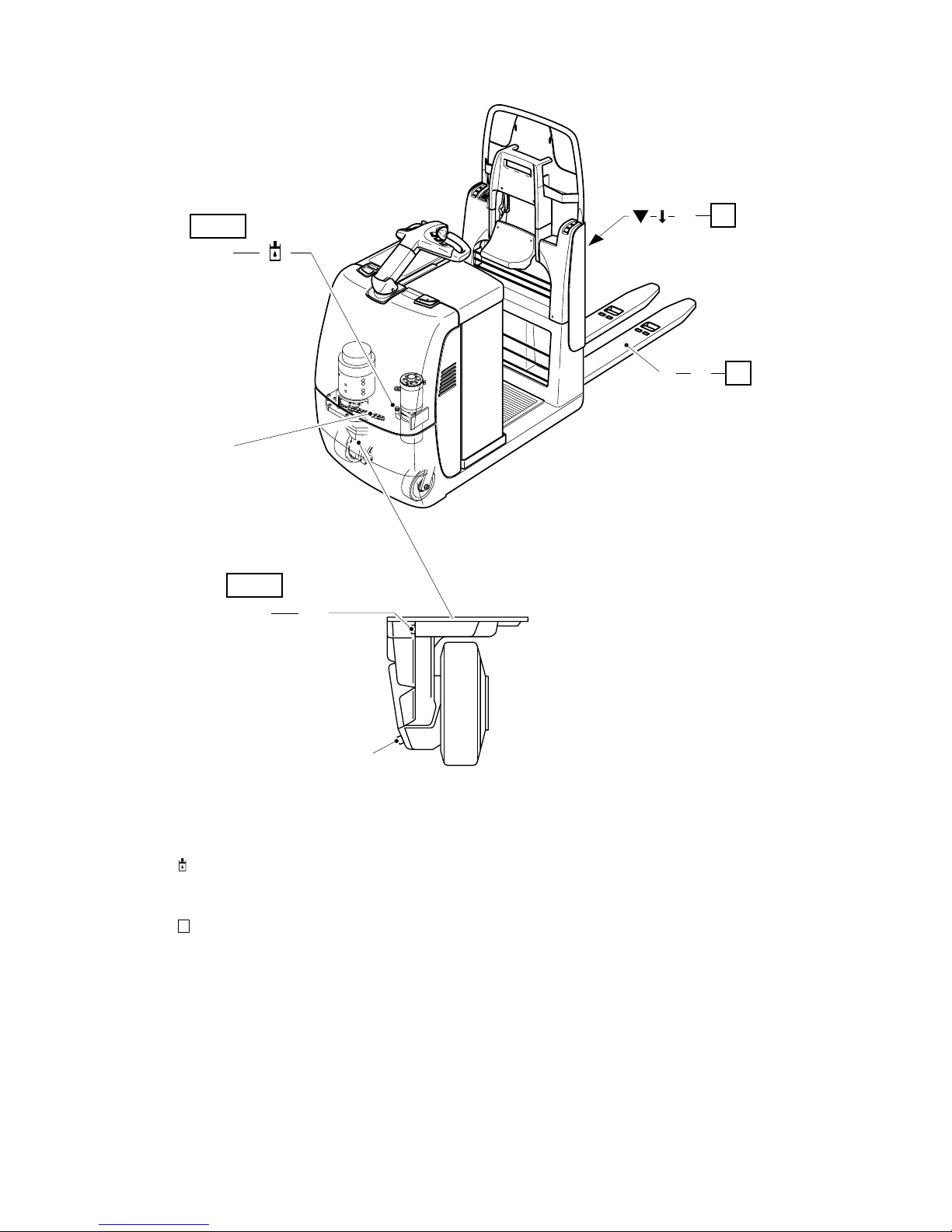
0307.GB
F 6
5 Lubrication schedule ECE 220
g Gliding surfaces
s Grease nipples
Filler plug for hydraulic oil
b Filler plug for gear oil
a Drain plug for gear oil
Cold store usage
1)
Compound for cold store usage 1:1
A + CA0,7 l
1)
G
a
B
1,4 l
B + C
b
1)
s
E
F
F
E
0307.GB
F 6
5 Lubrication schedule ECE 220
g Gliding surfaces
s Grease nipples
Filler plug for hydraulic oil
b Filler plug for gear oil
a Drain plug for gear oil
Cold store usage
1)
Compound for cold store usage 1:1
A + CA0,7 l
1)
G
a
B
1,4 l
B + C
b
1)
s
E
F
F
E
Page 60

F 7
0307.GB
5.1 Fuels, coolants and lubricants
Handling consumption type material: Consumption type material must always be
handled properly. Manufacturer's instructions to be observed.
F
Improper handling is injurious to health, life, and environment. Consumption type materials must be stored in adequate containers. They might be inflammable and, therefore, must not come into contact with hot components or open fire.
When filling in consumption type materials use clean containers only. It is prohibited
to mix consumption type materials of different grades or qualitiies resp., except if mixing is expressively prescribed in these operating instructions.
Avoid spilling. Spilt liquid must be removed immediately using a suitable binding
agent, and the mixture of consumption type material and binding agent is to be disposed of according to the regulations.
Grease Data
Code Order no. Package
quantity
Model Used for
A 50449669 5,0 l H-LP 46,
DIN 51524
Hydraulic System
B 50449961 5,0 l SAE J306
75W-902
Transmission oil
C 29 200 810 5,0 l H-LP 10,
DIN 51524
Transmission,
Hydraulic System
E 29202050 1,0 kg Grease, Polylube
GA 352P
Lubrication
G 29 201 280 0,4 l Chain spray Chains
Code Saponification Dew point
°C
Worked
penetration at
25 °C
NLG1 class Application
temperature °C
E Lithium >220 280 - 310 2 -35/+120
F 7
0307.GB
5.1 Fuels, coolants and lubricants
Handling consumption type material: Consumption type material must always be
handled properly. Manufacturer's instructions to be observed.
F
Improper handling is injurious to health, life, and environment. Consumption type ma-
terials must be stored in adequate containers. They might be inflammable and, there-
fore, must not come into contact with hot components or open fire.
When filling in consumption type materials use clean containers only. It is prohibited
to mix consumption type materials of different grades or qualitiies resp., except if mix-
ing is expressively prescribed in these operating instructions.
Avoid spilling. Spilt liquid must be removed immediately using a suitable binding
agent, and the mixture of consumption type material and binding agent is to be dis-
posed of according to the regulations.
Grease Data
Code Order no. Package
quantity
Model Used for
A 50449669 5,0 l H-LP 46,
DIN 51524
Hydraulic System
B 50449961 5,0 l SAE J306
75W-902
Transmission oil
C 29 200 810 5,0 l H-LP 10,
DIN 51524
Transmission,
Hydraulic System
E 29202050 1,0 kg Grease, Polylube
GA 352P
Lubrication
G 29 201 280 0,4 l Chain spray Chains
Code Saponification Dew point
°C
Worked
penetration at
25 °C
NLG1 class Application
temperature °C
E Lithium >220 280 - 310 2 -35/+120
Page 61

0307.GB
F 8
6 Instructions for the servicing operations
6.1 Preparing the truck for the performance of servicing and maintenance operations
All required safety measures must be taken to prevent any accidents in the course of
the servicing and maintenance operations. The following preparatory operations
must be performed:
– Park the truck and render it safe (refer to chapter E).
– Disconnect the battery plug so that the truck cannot be started by unauthorised per-
sons (refer to chapter D).
F
When work has to be performed under the raised fork or under the jacked up truck,
suitable measures must be taken to prevent any dropping, tilting or slipping of the fork
or truck. When lifting the truck, the instructions contained in chapter “Transportation
and commissioning” have to be observed.
When performing work on the parking brake, the truck must be secured against moving.
6.2 Tightening the wheel screws
The wheel screws of the drive wheel must be retightened in accordance with the servicing intervals indicated in the servicing checklist.
– Position the drive wheel (3) at right angles to the longitudinal axis of the truck.
– Using a socket wrench tighten all wheel bolts (1) through the hole (2) in the skirt in
the order indicated (torque 10 / 150 Nm).
M
Remove the socket wrench from the opening (2) after the wheel nuts have been tightened.
3
2
1
0307.GB
F 8
6 Instructions for the servicing operations
6.1 Preparing the truck for the performance of servicing and maintenance opera-
tions
All required safety measures must be taken to prevent any accidents in the course of
the servicing and maintenance operations. The following preparatory operations
must be performed:
– Park the truck and render it safe (refer to chapter E).
– Disconnect the battery plug so that the truck cannot be started by unauthorised per-
sons (refer to chapter D).
F
When work has to be performed under the raised fork or under the jacked up truck,
suitable measures must be taken to prevent any dropping, tilting or slipping of the fork
or truck. When lifting the truck, the instructions contained in chapter “Transportation
and commissioning” have to be observed.
When performing work on the parking brake, the truck must be secured against mov-
ing.
6.2 Tightening the wheel screws
The wheel screws of the drive wheel must be retightened in accordance with the serv-
icing intervals indicated in the servicing checklist.
– Position the drive wheel (3) at right angles to the longitudinal axis of the truck.
– Using a socket wrench tighten all wheel bolts (1) through the hole (2) in the skirt in
the order indicated (torque 10 / 150 Nm).
M
Remove the socket wrench from the opening (2) after the wheel nuts have been tight-
ened.
3
2
1
Page 62

F 9
0307.GB
6.3 Removing the front hood
– Open battery cover (refer to chapter D).
– Remove the screws (5).
– Lift front hood (4) and put aside.
Installation occurs in the reverse order of steps.
F
Do not drive the truck unless the hoods are closed and locked in the stipulated manner.
4
6
5
F 9
0307.GB
6.3 Removing the front hood
– Open battery cover (refer to chapter D).
– Remove the screws (5).
– Lift front hood (4) and put aside.
Installation occurs in the reverse order of steps.
F
Do not drive the truck unless the hoods are closed and locked in the stipulated man-
ner.
4
6
5
Page 63

0307.GB
F 10
6.4 Checking the electric fuses
– Prepare the truck for the servicing and maintenance operations
(refer to section 6.1).
– Remove the front hood (see section 6.3).
– Referring to the table, check all fuses for correct rating and damage; replace fuses
where required.
– Reinstall the front hood (see section 6.3).
Item Designation Protection of: Value
7 6F1 Battery discharge indicator /
operating hour meter
2 A
8 F1 Entire control circuit 10 A
9 3F6 Steering motor 30 A
10 1F1 Drive motor 300 A
11 2F1 Pump motor 150 A
10 11
9
8
7
Page 64

F 11
0307.GB
6.5 Recommissioning the truck
Recommissioning of the truck following the performance of cleaning or maintenance
work is permitted only after the following operations have been performed:
– Check the horn for proper functioning.
– Check the master switch for correct functioning.
– Check the brake for correct functioning.
– Lubricate truck according to lubrication schedule.
7 Decommissioning the fork lift truck
If the fork lift truck is to be decommissioned for more than two months, it must be
parked in a frost-free and dry location and all measures to be taken before, during and
following decommissioning must be performed as detailed below.
M
During decommissioning, the fork lift truck must be jacked up, ensuring that the
wheels are clear of the ground. Only this measure will ensure that wheels and wheel
bearings do not suffer damage.
If the fork lift truck is to be decommissioned for more than 6 months, additional measures must be discussed with the Service Department of the manufacturer.
7.1 Operations to be performed prior to decommissioning
– Thoroughly clean the fork lift truck.
– Check the brakes for correct function.
– Check the hydraulic oil level and top up if required (refer to chapter F).
– Apply a thin film of oil or grease to all parts not protected by a paint coating.
– Grease the fork lift truck as detailed in the lubrication chart (refer to chapter F).
– Recharge the battery (refer to chapter D).
– Disconnect and clean the battery. Apply pole grease to the battery poles.
Z
In addition to this, all instructions given by the battery supplier must be observed.
– Spray all exposed electrical contacts with a suitable contact spray.
7.2 Measures to be taken during decommissioning
Every 2 months:
– Recharge the battery (refer to chapter D).
M
Battery-operated fork lift trucks:
Regular recharging of the battery is very important; otherwise, exhaustive depletion
of the battery caused by self-discharging would occur. Owing to sulfatisation, this will
result in the destruction of the battery.
F 11
0307.GB
6.5 Recommissioning the truck
Recommissioning of the truck following the performance of cleaning or maintenance
work is permitted only after the following operations have been performed:
– Check the horn for proper functioning.
– Check the master switch for correct functioning.
– Check the brake for correct functioning.
– Lubricate truck according to lubrication schedule.
7 Decommissioning the fork lift truck
If the fork lift truck is to be decommissioned for more than two months, it must be
parked in a frost-free and dry location and all measures to be taken before, during and
following decommissioning must be performed as detailed below.
M
During decommissioning, the fork lift truck must be jacked up, ensuring that the
wheels are clear of the ground. Only this measure will ensure that wheels and wheel
bearings do not suffer damage.
If the fork lift truck is to be decommissioned for more than 6 months, additional meas-
ures must be discussed with the Service Department of the manufacturer.
7.1 Operations to be performed prior to decommissioning
– Thoroughly clean the fork lift truck.
– Check the brakes for correct function.
– Check the hydraulic oil level and top up if required (refer to chapter F).
– Apply a thin film of oil or grease to all parts not protected by a paint coating.
– Grease the fork lift truck as detailed in the lubrication chart (refer to chapter F).
– Recharge the battery (refer to chapter D).
– Disconnect and clean the battery. Apply pole grease to the battery poles.
Z
In addition to this, all instructions given by the battery supplier must be observed.
– Spray all exposed electrical contacts with a suitable contact spray.
7.2 Measures to be taken during decommissioning
Every 2 months:
– Recharge the battery (refer to chapter D).
M
Battery-operated fork lift trucks:
Regular recharging of the battery is very important; otherwise, exhaustive depletion
of the battery caused by self-discharging would occur. Owing to sulfatisation, this will
result in the destruction of the battery.
Page 65

0307.GB
F 12
7.3 Recommissioning the truck
– Thoroughly clean the fork lift truck.
– Lubricate the fork lift truck according to the lubrication chart (refer to chapter F).
– Clean the battery. Grease the pole screws using pole grease and reconnect the
battery.
– Recharge the battery (refer to chapter D).
– Check if the gear oil contains condensed water and change if required.
– Check if the hydraulic oil contains condensed water and change if required.
– Start up the fork lift truck (refer to chapter E).
Z
Battery-operated fork lift trucks:
If switching troubles are experienced in the electric system, spray the exposed contacts with contact spray and remove any oxide layer on the contacts of the operating
controls by repeated operation.
F
Perform several brake tests immediately after recommissioning the truck.
8 Safety checks to be performed at regular intervals and following any untoward
incidents (D: Accident prevention check according to BGV D27)
At least once yearly, or after any untoward incident, the fork lift truck has to be chekked by a qualified inspector. The inspector must assess the condition of the truck from
a standpoint purely concerned with safety aspects, uninfluenced by any company or
economic circumstances. The inspector must be adequately informed and experienced to be able to assess the condition of the fork lift truck and the effectiveness of
the safety installations based on the technical rules and principles governing the inspection of fork lift trucks.
The inspection must comprise a comprehensive check of the technical condition of
the fork lift truck with regard to accident prevention aspects. Apart from this, the fork
lift truck must be thoroughly inspected for damage possibly caused by incorrect use
of the fork lift truck. The inspection results must be recorded in an inspection report
which must be kept available for a period spanning at least the next two inspection
intervals.
The user has to ensure that all defects are eliminated without delay.
Z
The manufacturer has set up a special safety service with specially qualified staff. As
visual proof that the fork lift truck has passed the safety inspection, a plaque is affixed
to it. This plaque indicates in which month of which year the next test will be due.
0307.GB
F 12
7.3 Recommissioning the truck
– Thoroughly clean the fork lift truck.
– Lubricate the fork lift truck according to the lubrication chart (refer to chapter F).
– Clean the battery. Grease the pole screws using pole grease and reconnect the
battery.
– Recharge the battery (refer to chapter D).
– Check if the gear oil contains condensed water and change if required.
– Check if the hydraulic oil contains condensed water and change if required.
– Start up the fork lift truck (refer to chapter E).
Z
Battery-operated fork lift trucks:
If switching troubles are experienced in the electric system, spray the exposed con-
tacts with contact spray and remove any oxide layer on the contacts of the operating
controls by repeated operation.
F
Perform several brake tests immediately after recommissioning the truck.
8 Safety checks to be performed at regular intervals and following any untoward
incidents (D: Accident prevention check according to BGV D27)
At least once yearly, or after any untoward incident, the fork lift truck has to be chek-
ked by a qualified inspector. The inspector must assess the condition of the truck from
a standpoint purely concerned with safety aspects, uninfluenced by any company or
economic circumstances. The inspector must be adequately informed and experi-
enced to be able to assess the condition of the fork lift truck and the effectiveness of
the safety installations based on the technical rules and principles governing the in-
spection of fork lift trucks.
The inspection must comprise a comprehensive check of the technical condition of
the fork lift truck with regard to accident prevention aspects. Apart from this, the fork
lift truck must be thoroughly inspected for damage possibly caused by incorrect use
of the fork lift truck. The inspection results must be recorded in an inspection report
which must be kept available for a period spanning at least the next two inspection
intervals.
The user has to ensure that all defects are eliminated without delay.
Z
The manufacturer has set up a special safety service with specially qualified staff. As
visual proof that the fork lift truck has passed the safety inspection, a plaque is affixed
to it. This plaque indicates in which month of which year the next test will be due.
Page 66

1
0506.GB
Instructions for use
Jungheinrich traction battery
Table of contents
1 Jungheinrich traction battery
with positive tubular plates type EPzS and EPzB.......................................... 2-6
Type plate Jungheinrich traction battery............................................ 7
Instruction for use
Aquamatic/BFS III water refilling system ......................................................8-12
2 Jungheinrich traction battery
Maintenance free traction batteries with positive tubular plates type EPzV
and EPzV-BS
............................................................................................13-17
Type plate Jungheinrich traction battery............................................ 17
Page 67

0506.GB
2
1 Jungheinrich traction battery
with positive tubular plates type EPzS and EPzB
Rating Data
1. Nominal capacity C5: See type plate
2. Nominal voltage: 2,0 V x No of cells
3. Discharge current:: C5/5h
4. Nominal S.G. of electrolyte*
Type EPzS: 1,29 kg/l
Type EPzB: 1,29 kg/l
5. Rated temperature: 30° C
6. Nominal electrolyte level: up to electrolyte level mark „max.“
* Will be reached within the first 10 cycles.
•Pay attention to the operation instruction and fix them close to the battery!
•Work on batteries to be carried out by skilled personnel only!
•Use protective glasses and clothes when working on batteries!
•Pay attention to the accident prevention rules as well as DIN EN 50272-3, DIN
50110-1!
•No smoking!
•Do not expose batteries to naked flames, glowing embers or sparks, as it may
cause the battery to explode!
•Acid splashes in the eyes or on the skin must be washed with water. In case of
accident consult a doctor immediately!
•Clothing contaminated by acid should be washed in water.
•Risk of explosion and fire, avoid short circuits!
•Electrolyte is highly corrosive!
•Batteries and cells are heavy!
•Ensure secure installation! Use only suitable handling equipment e.g. lifting gear
in accordance with VDI 3616.
•Dangerous electrical voltage!
•Caution! Metal parts of the battery are always live. Do not place tools or other metal objects on the battery!
0506.GB
2
1 Jungheinrich traction battery
with positive tubular plates type EPzS and EPzB
Rating Data
1. Nominal capacity C5: See type plate
2. Nominal voltage: 2,0 V x No of cells
3. Discharge current:: C5/5h
4. Nominal S.G. of electrolyte*
Type EPzS: 1,29 kg/l
Type EPzB: 1,29 kg/l
5. Rated temperature: 30° C
6. Nominal electrolyte level: up to electrolyte level mark „max.“
* Will be reached within the first 10 cycles.
•Pay attention to the operation instruction and fix them close to the battery!
•Work on batteries to be carried out by skilled personnel only!
•Use protective glasses and clothes when working on batteries!
•Pay attention to the accident prevention rules as well as DIN EN 50272-3, DIN
50110-1!
•No smoking!
•Do not expose batteries to naked flames, glowing embers or sparks, as it may
cause the battery to explode!
•Acid splashes in the eyes or on the skin must be washed with water. In case of
accident consult a doctor immediately!
•Clothing contaminated by acid should be washed in water.
•Risk of explosion and fire, avoid short circuits!
•Electrolyte is highly corrosive!
•Batteries and cells are heavy!
•Ensure secure installation! Use only suitable handling equipment e.g. lifting gear
in accordance with VDI 3616.
•Dangerous electrical voltage!
•Caution! Metal parts of the battery are always live. Do not place tools or other me-
tal objects on the battery!
Page 68

3
0506.GB
Ignoring the operation instructions, repair with non-original parts or using additives for
the electrolyte will render the warranty void.
For batteries in classes I and II the instructions for maintaining the appropriate
protection class during operation must be complied with (see relevant certificate).
1. Commissioning filled and charged batteries. For commissioning of unfilled
batteries see separate instructions!
The battery should be inspected to ensure it is in perfect physical condition.
The charger cables must be connected to ensure a good contact, taking care that the
polarity is correct. Otherwise battery, vehicle or charger could be damaged.
The specified torque loading for the polscrews of the charger cables and connectors
are:
The level of the electrolyte must be checked. If it is below the antisurge baffle or the
top of the separator it must first be topped up to this height with purified water.
The battery is then charged as in item 2.2.
The electrolyte should be topped up to the specified level with purified water.
2. Operation
DIN EN 50272-3 «Traction batteries for industrial trucks» is the standard which applies to the operation traction batteries in industrial trucks.
2.1 Discharging
Be sure that all breather holes are not sealed or covered.
Electrical connections (e.g. plugs) must only be made or broken in the open circuit
condition.
To achieve the optimum life for the battery, operating discharges of more than 80%
of the rated capacity should be avoided (deep discharge).
This corresponds to an electrolyte specific gravity of 1.13 kg/l at the end of the discharge. Discharged batteries must be recharged immediately and must not be left
discharged. This also applies to partially discharged batteries.
2.2 Charging
Only direct current must be used for charging. All charging procedures in accordance
with DIN 41773 and DIN 41774 are permitted. Only connect the battery assigned to
a charger, suitable for the size of battery, in order to avoid overloading of the electric
cables and contacts, unacceptable gassing and the escape of electrolyte from the
cells.
In the gassing stage the current limits given in DIN EN 50272-3 must not be exceeded. If the charger was not purchased together with the battery it is best to have its
suitability checked by the manufacturers service department. When charging, proper
provision must be made for venting of the charging gases.
steel
M 10 23 ± 1 Nm
3
0506.GB
Ignoring the operation instructions, repair with non-original parts or using additives for
the electrolyte will render the warranty void.
For batteries in classes I and II the instructions for maintaining the appropriate
protection class during operation must be complied with (see relevant certificate).
1. Commissioning filled and charged batteries. For commissioning of unfilled
batteries see separate instructions!
The battery should be inspected to ensure it is in perfect physical condition.
The charger cables must be connected to ensure a good contact, taking care that the
polarity is correct. Otherwise battery, vehicle or charger could be damaged.
The specified torque loading for the polscrews of the charger cables and connectors
are:
The level of the electrolyte must be checked. If it is below the antisurge baffle or the
top of the separator it must first be topped up to this height with purified water.
The battery is then charged as in item 2.2.
The electrolyte should be topped up to the specified level with purified water.
2. Operation
DIN EN 50272-3 «Traction batteries for industrial trucks» is the standard which ap-
plies to the operation traction batteries in industrial trucks.
2.1 Discharging
Be sure that all breather holes are not sealed or covered.
Electrical connections (e.g. plugs) must only be made or broken in the open circuit
condition.
To achieve the optimum life for the battery, operating discharges of more than 80%
of the rated capacity should be avoided (deep discharge).
This corresponds to an electrolyte specific gravity of 1.13 kg/l at the end of the di-
scharge. Discharged batteries must be recharged immediately and must not be left
discharged. This also applies to partially discharged batteries.
2.2 Charging
Only direct current must be used for charging. All charging procedures in accordance
with DIN 41773 and DIN 41774 are permitted. Only connect the battery assigned to
a charger, suitable for the size of battery, in order to avoid overloading of the electric
cables and contacts, unacceptable gassing and the escape of electrolyte from the
cells.
In the gassing stage the current limits given in DIN EN 50272-3 must not be excee-
ded. If the charger was not purchased together with the battery it is best to have its
suitability checked by the manufacturers service department. When charging, proper
provision must be made for venting of the charging gases.
steel
M 10 23 ± 1 Nm
Page 69

0506.GB
4
Battery container lids and the covers of battery compartments must be opened or removed. The vent plugs should stay on the cells and remain closed.
With the charger switched off connect up the battery, ensuring that the polarity is correct. (positive to positive, negative to negative). Now switch on the charger. When
charging the temperature of the electrolyte rises by about 10°C, so charging should
only begin if the electrolyte temperature is below 45°C. The electrolyte temperature
of batteries should be at least +10°C before charging otherwise a full charge will not
be achieved.
A charge is finished when the specific gravity of the electrolyte and the battery voltage
have remained constant for two hours. Special instructions for the operation of batteries in hazardous areas. This concerns batteries which are used in accordance with
EN 50014, DIN VDE 0170/0171 Ex (in areas with a firedamp hazard) or Ex II (in potentially explosive areas). During charging and subsequent gassing the container lids
must be removed or opened so that the explosive mixture of gases loses its flammability due to adequate ventilation. The containers for batteries with plate protection
packs must not be closed until at least half an hour after charging has past.
2.3 Equalising charge
Equalising charges are used to safeguard the life of the battery and to maintain its
capacity. They are necessary after deep discharges, repeated incomplete recharges
and charges to an IU characteristic curve. Equalising charges are carried out following normal charging. The charging current must not exceed 5 A/100 Ah of rated capacity (end of charge - see point 2.2).
Watch the temperature!
2.4 Temperature
An electrolyte temperature of 30°C is specified as the rated temperature. Higher temperatures shorten the life of the battery, lower temperatures reduce the capacity available. 55°C is the upper temperature limit and is not acceptable as an operating temperature.
2.5 Electrolyte
The rated specific gravity (S. G.) of the electrolyte is related to a temperature of 30°C
and the nominal electrolyte level in the cell in fully charged condition. Higher temperatures reduce the specified gravity of the electrolyte, lower temperatures increase it.
The temperature correction factor is -0.0007 kg/l per °C, e.g. an electrolyte specific
gravity of 1.28 kg/l at 45°C corresponds to an S.G. of 1.29 kg/l at 30°C.
The electrolyte must conform to the purity regulations in DIN 43530 part 2.
0506.GB
4
Battery container lids and the covers of battery compartments must be opened or re-
moved. The vent plugs should stay on the cells and remain closed.
With the charger switched off connect up the battery, ensuring that the polarity is cor-
rect. (positive to positive, negative to negative). Now switch on the charger. When
charging the temperature of the electrolyte rises by about 10°C, so charging should
only begin if the electrolyte temperature is below 45°C. The electrolyte temperature
of batteries should be at least +10°C before charging otherwise a full charge will not
be achieved.
A charge is finished when the specific gravity of the electrolyte and the battery voltage
have remained constant for two hours. Special instructions for the operation of batte-
ries in hazardous areas. This concerns batteries which are used in accordance with
EN 50014, DIN VDE 0170/0171 Ex (in areas with a firedamp hazard) or Ex II (in po-
tentially explosive areas). During charging and subsequent gassing the container lids
must be removed or opened so that the explosive mixture of gases loses its flamma-
bility due to adequate ventilation. The containers for batteries with plate protection
packs must not be closed until at least half an hour after charging has past.
2.3 Equalising charge
Equalising charges are used to safeguard the life of the battery and to maintain its
capacity. They are necessary after deep discharges, repeated incomplete recharges
and charges to an IU characteristic curve. Equalising charges are carried out follo-
wing normal charging. The charging current must not exceed 5 A/100 Ah of rated ca-
pacity (end of charge - see point 2.2).
Watch the temperature!
2.4 Temperature
An electrolyte temperature of 30°C is specified as the rated temperature. Higher tem-
peratures shorten the life of the battery, lower temperatures reduce the capacity avai-
lable. 55°C is the upper temperature limit and is not acceptable as an operating tem-
perature.
2.5 Electrolyte
The rated specific gravity (S. G.) of the electrolyte is related to a temperature of 30°C
and the nominal electrolyte level in the cell in fully charged condition. Higher tempe-
ratures reduce the specified gravity of the electrolyte, lower temperatures increase it.
The temperature correction factor is -0.0007 kg/l per °C, e.g. an electrolyte specific
gravity of 1.28 kg/l at 45°C corresponds to an S.G. of 1.29 kg/l at 30°C.
The electrolyte must conform to the purity regulations in DIN 43530 part 2.
Page 70

5
0506.GB
3. Maintenance
3.1 Daily
Charge the battery after every discharge. Towards the end of charge the electrolyte
level should be checked and if necessary topped up to the specified level with purified
water. The electrolyte level must not fall below the anti-surge baffle or the top of the
separator or the electrolyte „min“ level mark.
3.2 Weekly
Visual inspection after recharging for signs of dirt and mechanical damage. If the battery is charged regularly with a IU characteristic curve an equalising charge must be
carried out (see point 2.3).
3.3 Monthly
At the end of the charge the voltages of all cells or bloc batteries should be measured
with the charger switched on, and recorded. After charging has ended the specific
gravity and the temperature of the electrolyte in all cells should be measured and recorded.
If significant changes from earlier measurements or differences between the cells or
bloc batteries are found further testing and maintenance by the service department
should be requested.
3.4 Annually
In accordance with DIN VDE 0117 at least once per year, the insulation resistance of
the truck and the battery must be checked by an electrical specialist.
The tests on the insulation resistance of the battery must be conducted in accordance
with DIN EN 60254-1.
The insulation resistance of the battery thus determined must not be below a value of
50 Ω per Volt of nominal voltage, in compliance with DIN EN 50272-3.
For batteries up to 20 V nominal voltage the minimum value is 1000 Ω.
4. Care of the battery
The battery should always be kept clean and dry to prevent tracking currents. Cleaning must be done in accordance with the ZVEI code of practice «The Cleaning of
Vehicle Traction batteries».
Any liquid in the battery tray must be extracted and disposed of in the prescribed manner. Damage to the insulation of the tray should be repaired after cleaning, to ensure
that the insulation value complies DIN EN 50272-3 and to prevent tray corrosion. If it
is necessary to remove cells it is best to call in our service department for this.
5
0506.GB
3. Maintenance
3.1 Daily
Charge the battery after every discharge. Towards the end of charge the electrolyte
level should be checked and if necessary topped up to the specified level with purified
water. The electrolyte level must not fall below the anti-surge baffle or the top of the
separator or the electrolyte „min“ level mark.
3.2 Weekly
Visual inspection after recharging for signs of dirt and mechanical damage. If the bat-
tery is charged regularly with a IU characteristic curve an equalising charge must be
carried out (see point 2.3).
3.3 Monthly
At the end of the charge the voltages of all cells or bloc batteries should be measured
with the charger switched on, and recorded. After charging has ended the specific
gravity and the temperature of the electrolyte in all cells should be measured and re-
corded.
If significant changes from earlier measurements or differences between the cells or
bloc batteries are found further testing and maintenance by the service department
should be requested.
3.4 Annually
In accordance with DIN VDE 0117 at least once per year, the insulation resistance of
the truck and the battery must be checked by an electrical specialist.
The tests on the insulation resistance of the battery must be conducted in accordance
with DIN EN 60254-1.
The insulation resistance of the battery thus determined must not be below a value of
50 Ω per Volt of nominal voltage, in compliance with DIN EN 50272-3.
For batteries up to 20 V nominal voltage the minimum value is 1000 Ω.
4. Care of the battery
The battery should always be kept clean and dry to prevent tracking currents. Clea-
ning must be done in accordance with the ZVEI code of practice «The Cleaning of
Vehicle Traction batteries».
Any liquid in the battery tray must be extracted and disposed of in the prescribed man-
ner. Damage to the insulation of the tray should be repaired after cleaning, to ensure
that the insulation value complies DIN EN 50272-3 and to prevent tray corrosion. If it
is necessary to remove cells it is best to call in our service department for this.
Page 71

0506.GB
6
5. Storage
If batteries are taken out of service for a lengthy period they should be stored in the
fully charged condition in a dry, frost-free room. To ensure the battery is always ready
for use a choice of charging methods can be made:
1. a monthly equalising charge as in point 2.3
2. float charging at a charging voltage of 2.23 V x the number of cells. The storage
time should be taken into account when considering the life of the battery.
6. Malfunctions
If malfunctions are found on the battery or the charger our service department should
be called in without delay. The measurements taken in point 3.3 will facilitate fault finding and their elimination.
A service contract with us will make it easier to detect and correct faults in good time.
Back to the manufacturer!
Batteries with this sign must be recycled.
Batteries which are not returned for the recycling process must be
disposed of as hazardous waste!
We reserve the right make technical modification.
0506.GB
6
5. Storage
If batteries are taken out of service for a lengthy period they should be stored in the
fully charged condition in a dry, frost-free room. To ensure the battery is always ready
for use a choice of charging methods can be made:
1. a monthly equalising charge as in point 2.3
2. float charging at a charging voltage of 2.23 V x the number of cells. The storage
time should be taken into account when considering the life of the battery.
6. Malfunctions
If malfunctions are found on the battery or the charger our service department should
be called in without delay. The measurements taken in point 3.3 will facilitate fault fin-
ding and their elimination.
A service contract with us will make it easier to detect and correct faults in good time.
Back to the manufacturer!
Batteries with this sign must be recycled.
Batteries which are not returned for the recycling process must be
disposed of as hazardous waste!
We reserve the right make technical modification.
Page 72

7
0506.GB
7.Type plate, Jungheinrich traction battery
* CE mark is only for batteries with a nominal voltage greater than 75 volt.
Item Designation Item Designation
1 Logo 8 Recycling symbol
2 Battery designation 9 Dustbin/material
3 Battery type 10 Nominal battery voltage
4 Battery number 11 Nominal battery capacity
5 Battery tray number 12 Number of battery cells
6 Delivery date 13 Battery weight
7 Battery manufacturer's logo 14 Safety instructions and warnings
Typ
1
Type
Nennspannung
5
Nominal Voltage
Hersteller
9
Manufacturer
Kapazität
6
Capacity
Zellenzahl
7
Number of Cells
Batteriegewicht min/max
8
Battery mass min/max
Serien-Nr.
3
Serial-Nr.
Lieferanten Nr.
4
Supplier No.
Baujahr
2
Year of manufacture
Jungheinrich AG, D-22047 Hamburg, Germany
5
Pb Pb
2/3 6
5
11
13
1
14
4
10
12
7
8
9
7
0506.GB
7.Type plate, Jungheinrich traction battery
* CE mark is only for batteries with a nominal voltage greater than 75 volt.
Item Designation Item Designation
1 Logo 8 Recycling symbol
2 Battery designation 9 Dustbin/material
3 Battery type 10 Nominal battery voltage
4 Battery number 11 Nominal battery capacity
5 Battery tray number 12 Number of battery cells
6 Delivery date 13 Battery weight
7 Battery manufacturer's logo 14 Safety instructions and warnings
Typ
1
Type
Nennspannung
5
Nominal Voltage
Hersteller
9
Manufacturer
Kapazität
6
Capacity
Zellenzahl
7
Number of Cells
Batteriegewicht min/max
8
Battery mass min/max
Serien-Nr.
3
Serial-Nr.
Lieferanten Nr.
4
Supplier No.
Baujahr
2
Year of manufacture
Jungheinrich AG, D-22047 Hamburg, Germany
5
Pb Pb
2/3 6
5
11
13
1
14
4
10
12
7
8
9
Page 73
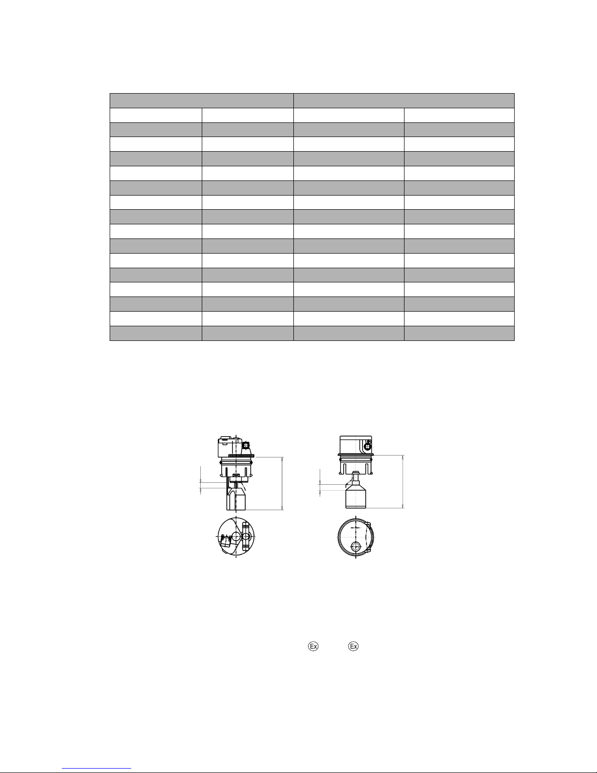
0506.GB
8
Aquamatic/BFS III water refilling system for Jungheinrich traction battery with
EPzS and EPzB cells with tubular positive plates
Aquamatic plug arrangement for the Operating Instructions
* The cell series comprise cells with two to ten (twelve) positive plates, e.g. column
EPzS. 2/120 - 10/600.
These are cells with the positive plate 60Ah. The type designation of a cell is e.g.
2 EPzS 120.
Non-adherence to the operating instructions, repairs carried out with non-original
spare parts, unauthorised interference, and the use of additives for the electrolytes
(alleged improvement agents) will invalidate any claim for warranty.
When using batteries which comply with I and II, it is important to follow the instructions on maintaining the respective protection class during operation (see associated certification).
Cell series* Aquamatic plug type (length)
EPzS EPzB Frötek (yellow) BFS (black)
2/120 – 10/ 600 2/ 42 – 12/ 252 50,5 mm 51,0 mm
2/160 – 10/ 800 2/ 64 – 12/ 384 50,5 mm 51,0 mm
– 2/ 84 – 12/ 504 50,5 mm 51,0 mm
– 2/110 – 12/ 660 50,5 mm 51,0 mm
– 2/130 – 12/ 780 50,5 mm 51,0 mm
– 2/150 – 12/ 900 50,5 mm 51,0 mm
– 2/172 – 12/1032 50,5 mm 51,0 mm
– 2/200 – 12/1200 56,0 mm 56,0 mm
– 2/216 – 12/1296 56,0 mm 56,0 mm
2/180 – 10/900 – 61,0 mm 61,0 mm
2/210 – 10/1050 – 61,0 mm 61,0 mm
2/230 – 10/1150 – 61,0 mm 61,0 mm
2/250 – 10/1250 – 61,0 mm 61,0 mm
2/280 – 10/1400 – 72,0 mm 66,0 mm
2/310 – 10/1550 – 72,0 mm 66,0 mm
stroke
length
stroke
length
Aquamatic plug with
diagnostics hole
Aquamatic plug BFS III with
diagnostics hole
0506.GB
8
Aquamatic/BFS III water refilling system for Jungheinrich traction battery with
EPzS and EPzB cells with tubular positive plates
Aquamatic plug arrangement for the Operating Instructions
* The cell series comprise cells with two to ten (twelve) positive plates, e.g. column
EPzS. 2/120 - 10/600.
These are cells with the positive plate 60Ah. The type designation of a cell is e.g.
2 EPzS 120.
Non-adherence to the operating instructions, repairs carried out with non-original
spare parts, unauthorised interference, and the use of additives for the electrolytes
(alleged improvement agents) will invalidate any claim for warranty.
When using batteries which comply with I and II, it is important to follow the in-
structions on maintaining the respective protection class during operation (see asso-
ciated certification).
Cell series* Aquamatic plug type (length)
EPzS EPzB Frötek (yellow) BFS (black)
2/120 – 10/ 600 2/ 42 – 12/ 252 50,5 mm 51,0 mm
2/160 – 10/ 800 2/ 64 – 12/ 384 50,5 mm 51,0 mm
– 2/ 84 – 12/ 504 50,5 mm 51,0 mm
– 2/110 – 12/ 660 50,5 mm 51,0 mm
– 2/130 – 12/ 780 50,5 mm 51,0 mm
– 2/150 – 12/ 900 50,5 mm 51,0 mm
– 2/172 – 12/1032 50,5 mm 51,0 mm
– 2/200 – 12/1200 56,0 mm 56,0 mm
– 2/216 – 12/1296 56,0 mm 56,0 mm
2/180 – 10/900 – 61,0 mm 61,0 mm
2/210 – 10/1050 – 61,0 mm 61,0 mm
2/230 – 10/1150 – 61,0 mm 61,0 mm
2/250 – 10/1250 – 61,0 mm 61,0 mm
2/280 – 10/1400 – 72,0 mm 66,0 mm
2/310 – 10/1550 – 72,0 mm 66,0 mm
stroke
length
stroke
length
Aquamatic plug with
diagnostics hole
Aquamatic plug BFS III with
diagnostics hole
Page 74

9
0506.GB
Diagrammatic view
Equipment for the
water refilling system
1. Water tank
2. Level switch
3. Discharge point with ball
valve
4. Discharge point with solenoid valve
5. Charger
6. Sealing coupler
7. Closing nipple
8. Ion exchange cartridge with
conductance meter and
solenoid valve
9. Connection for untreated
water
10. Charging lead
1. Design
The Aquamatic/BFS battery water refilling systems are used for automatically adjusting the nominal electrolyte level. Venting holes are provided for letting off the gases
which arise during charging. In addition to the optical level indicator, the plug systems
also have a diagnostics hole for measuring the temperature and the electrolyte density. All battery cells of the design series EPzS; EPzB can be equipped with the Aquamatic/BFS filling systems. The water can be refilled by means of a central sealing
coupler through the hose connections in the individual Aquamatic/BFS plugs.
2. Application
The Aquamatic/BFS battery water refilling system is used in traction batteries for
forklift trucks. The water refilling system is provided with a central water connection
for the water supply. Soft PVC hose is used for this connection and for the hose connections for the individual plugs. The hose ends are put onto the hose connection
sleeves located on the T or < pieces.
3. Function
The quantity of water required in the refilling process is controlled by the valve located
in the plug in combination with the float and the float rods. In the Aquamatic System
the existing water pressure at the valve turns off the water supply and ensures that
the valve closes securely. When the maximum filling level is reached in the BFS system, the float and the float rods through a lever system close the valve with five times
the buoyant force and consequently interrupt the water supply reliably.
at least 3 m
9
0506.GB
Diagrammatic view
Equipment for the
water refilling system
1. Water tank
2. Level switch
3. Discharge point with ball
valve
4. Discharge point with sole-
noid valve
5. Charger
6. Sealing coupler
7. Closing nipple
8. Ion exchange cartridge with
conductance meter and
solenoid valve
9. Connection for untreated
water
10. Charging lead
1. Design
The Aquamatic/BFS battery water refilling systems are used for automatically adjus-
ting the nominal electrolyte level. Venting holes are provided for letting off the gases
which arise during charging. In addition to the optical level indicator, the plug systems
also have a diagnostics hole for measuring the temperature and the electrolyte den-
sity. All battery cells of the design series EPzS; EPzB can be equipped with the Aqua-
matic/BFS filling systems. The water can be refilled by means of a central sealing
coupler through the hose connections in the individual Aquamatic/BFS plugs.
2. Application
The Aquamatic/BFS battery water refilling system is used in traction batteries for
forklift trucks. The water refilling system is provided with a central water connection
for the water supply. Soft PVC hose is used for this connection and for the hose con-
nections for the individual plugs. The hose ends are put onto the hose connection
sleeves located on the T or < pieces.
3. Function
The quantity of water required in the refilling process is controlled by the valve located
in the plug in combination with the float and the float rods. In the Aquamatic System
the existing water pressure at the valve turns off the water supply and ensures that
the valve closes securely. When the maximum filling level is reached in the BFS sys-
tem, the float and the float rods through a lever system close the valve with five times
the buoyant force and consequently interrupt the water supply reliably.
at least 3 m
Page 75

0506.GB
10
4. Filling (manual/automatic)
The batteries should be filled with battery water as soon as possible before the battery
charging comes to an end; this ensures that the refilled water quantity is mixed with
the electrolyte. In normal operation it is usually sufficient to fill once a week.
5. Connection pressure
The water refilling unit is to be operated in such a way that the water pressure in the
water pipe is between 0.3 bars and 1.8 bars. The Aquamatic System has an operating
pressure range of between 0.2 bars and 0.6 bars. The BFS system has an operating
pressure range of 0.3 bars to 1.8 bars. Deviations from the pressure ranges impair
the system's functional reliability. This wide pressure range permits three types of filling.
5.1 Falling water
The height of the tank is chosen to suit whichever water refilling system is used. For
the Aquamatic System the installation height is 2 m to 6 m and for the BFS system
the installation height is 3 m to 18 m over the battery surface.
5.2 Pressurised water
The pressure-reducing valve in the Aquamatic System is set from 0.2 bars to 0.6 bars
and from 0.3 bars to 1.8 bars in the BFS system.
5.3 Water Refill Trolley (serviceMobil)
The submergible pump located in the ServiceMobil's tank generates the necessary
filling pressure. No difference in height is permitted between the standing level of the
ServiceMobil and the standing level of the battery.
6. Filling duration
The length of time needed to fill the batteries depends on the conditions under which
the battery is used, the ambient temperatures and the type of filling and/or the filling
pressure. The filling time is approx. 0.5 to 4 minutes. Where filling is manual, the water feed pipe must be separated from the battery after filling.
7. Water quality
Only refilling water which conforms in quality to DIN 43530 part 4 may be used to fill
the batteries. The refilling unit (tank, pipelines, valves etc.) may not contain any kind
of dirt which could impair the functional reliability of the Aquamatic/BFS plug. For
safety reasons it is recommendable to insert a filter element (optional) with a max.
passage opening of 100 to 300 µm into the battery's main supply pipe.
0506.GB
10
4. Filling (manual/automatic)
The batteries should be filled with battery water as soon as possible before the battery
charging comes to an end; this ensures that the refilled water quantity is mixed with
the electrolyte. In normal operation it is usually sufficient to fill once a week.
5. Connection pressure
The water refilling unit is to be operated in such a way that the water pressure in the
water pipe is between 0.3 bars and 1.8 bars. The Aquamatic System has an operating
pressure range of between 0.2 bars and 0.6 bars. The BFS system has an operating
pressure range of 0.3 bars to 1.8 bars. Deviations from the pressure ranges impair
the system's functional reliability. This wide pressure range permits three types of fil-
ling.
5.1 Falling water
The height of the tank is chosen to suit whichever water refilling system is used. For
the Aquamatic System the installation height is 2 m to 6 m and for the BFS system
the installation height is 3 m to 18 m over the battery surface.
5.2 Pressurised water
The pressure-reducing valve in the Aquamatic System is set from 0.2 bars to 0.6 bars
and from 0.3 bars to 1.8 bars in the BFS system.
5.3 Water Refill Trolley (serviceMobil)
The submergible pump located in the ServiceMobil's tank generates the necessary
filling pressure. No difference in height is permitted between the standing level of the
ServiceMobil and the standing level of the battery.
6. Filling duration
The length of time needed to fill the batteries depends on the conditions under which
the battery is used, the ambient temperatures and the type of filling and/or the filling
pressure. The filling time is approx. 0.5 to 4 minutes. Where filling is manual, the wa-
ter feed pipe must be separated from the battery after filling.
7. Water quality
Only refilling water which conforms in quality to DIN 43530 part 4 may be used to fill
the batteries. The refilling unit (tank, pipelines, valves etc.) may not contain any kind
of dirt which could impair the functional reliability of the Aquamatic/BFS plug. For
safety reasons it is recommendable to insert a filter element (optional) with a max.
passage opening of 100 to 300 µm into the battery's main supply pipe.
Page 76

11
0506.GB
8. Battery hose connections
Hose connections for the individual plugs are laid along the existing electric circuit.
No changes may be made.
9. Operating temperature
The temperature limit for battery operation is set at 55° C. Exceeding this temperature
damages the batteries. The battery filling systems may be operated within a temperature range of > 0° C to a maximum of 55° C.
CAUTION:
Batteries with automatic water refilling systems may only be operated in rooms
with temperatures > 0° C (as there is otherwise a danger that the systems may
freeze).
9.1 Diagnostics hole
To be able to measure the acid density and temperature easily, the water refilling systems must have a diagnostics hole with a 6.5 mm-diameter (Aquamatic plugs) or a
7.5 mm-diameter (BFS plugs).
9.2 Float
Different floats are used depending on the cell design and type.
9.3 Cleaning
The plug systems may only be cleaned with water. No parts of the plugs may come
in contact with soap or fabrics which contain solvents.
10. Accessories
10.1 Flow indicator
To monitor the filling process, a flow indicator can be inserted into the water feed pipe
on the battery side. During the filling process, the paddlewheel is turned by the flowing
water. When the filling process ends, the wheel stops and this indicates the end of
the filling process. (ident no.: 50219542).
10.2 Plug lifter
Only the appertaining special-purpose tool may be used to disassemble the plug systems (plug lifter). The greatest of care must be employed when prising out the plug to
prevent any damage to the plug systems.
11
0506.GB
8. Battery hose connections
Hose connections for the individual plugs are laid along the existing electric circuit.
No changes may be made.
9. Operating temperature
The temperature limit for battery operation is set at 55° C. Exceeding this temperature
damages the batteries. The battery filling systems may be operated within a tempe-
rature range of > 0° C to a maximum of 55° C.
CAUTION:
Batteries with automatic water refilling systems may only be operated in rooms
with temperatures > 0° C (as there is otherwise a danger that the systems may
freeze).
9.1 Diagnostics hole
To be able to measure the acid density and temperature easily, the water refilling sys-
tems must have a diagnostics hole with a 6.5 mm-diameter (Aquamatic plugs) or a
7.5 mm-diameter (BFS plugs).
9.2 Float
Different floats are used depending on the cell design and type.
9.3 Cleaning
The plug systems may only be cleaned with water. No parts of the plugs may come
in contact with soap or fabrics which contain solvents.
10. Accessories
10.1 Flow indicator
To monitor the filling process, a flow indicator can be inserted into the water feed pipe
on the battery side. During the filling process, the paddlewheel is turned by the flowing
water. When the filling process ends, the wheel stops and this indicates the end of
the filling process. (ident no.: 50219542).
10.2 Plug lifter
Only the appertaining special-purpose tool may be used to disassemble the plug sys-
tems (plug lifter). The greatest of care must be employed when prising out the plug to
prevent any damage to the plug systems.
Page 77

0506.GB
12
10.2.1 Clamping ring tool
The clamping ring tool is used to push on a clamping ring to increase the contact pressure of the hose connection on the plugs' hose couplings and to loosen it again.
10.3 Filter element
For safety reasons a filter element (ident no.: 50307282) can be fitted into the battery's main supply pipe for supplying battery water. This filter element has a maximum
passage cross-section of 100 to 300 µm and is designed as a bag filter.
10.4 Sealing coupler
The water is supplied to the water refilling systems (Aquamatic/BFS) through a central supply pipe. This is connected to the water supply system at the battery charging
station by means of a sealing coupler system. On the battery side a closing nipple
(ident no.: 50219538) is mounted and the customer must place a sealing coupler
construction on the water supply side (obtainable under ident. no.: 50219537).
11. Functional data
PS - self-sealing pressure: Aquamatic > 1.2 bars
BFS system none
D - rate of flow in the opened valve when the pressure is 0.1 bars: 350 ml/min
D1 - maximum permissible leakage rate in the closed valve when the pressure is at
0.1 bars: 2 ml/min
T - permissible temperature range: 0° C to a maximum of 65° C
Pa - operating pressure range: 0.2 to 0.6 bars in the Aquamatic system and
operating pressure range: 0.3 to 1.8 bars in the BFS system.
0506.GB
12
10.2.1 Clamping ring tool
The clamping ring tool is used to push on a clamping ring to increase the contact pres-
sure of the hose connection on the plugs' hose couplings and to loosen it again.
10.3 Filter element
For safety reasons a filter element (ident no.: 50307282) can be fitted into the batte-
ry's main supply pipe for supplying battery water. This filter element has a maximum
passage cross-section of 100 to 300 µm and is designed as a bag filter.
10.4 Sealing coupler
The water is supplied to the water refilling systems (Aquamatic/BFS) through a cen-
tral supply pipe. This is connected to the water supply system at the battery charging
station by means of a sealing coupler system. On the battery side a closing nipple
(ident no.: 50219538) is mounted and the customer must place a sealing coupler
construction on the water supply side (obtainable under ident. no.: 50219537).
11. Functional data
PS - self-sealing pressure: Aquamatic > 1.2 bars
BFS system none
D - rate of flow in the opened valve when the pressure is 0.1 bars: 350 ml/min
D1 - maximum permissible leakage rate in the closed valve when the pressure is at
0.1 bars: 2 ml/min
T - permissible temperature range: 0° C to a maximum of 65° C
Pa - operating pressure range: 0.2 to 0.6 bars in the Aquamatic system and
operating pressure range: 0.3 to 1.8 bars in the BFS system.
Page 78

13
0506.GB
2 Jungheinrich traction batterie
Maintenance free Jungheinrich traction batterie with positive tubular plates
type EPzV and EPzV-BS
Rating Data
1. Nominal capacity C5: See type plate
2. Nominal voltage: 2,0 Volt x No of cells
3. Discharge current: C5/5h
4. Rated temperature: 30° C
EPzV batteries are valve-regulated batteries with an immobilised electrolyte and where a water refilling isn’t permitted during the whole battery life. Instead of a vent plug
there are valves used, who will be destroyed when they are opened.
When operating valve-regulated lead-acid batteries the same safety requirements as
for vented cells apply to protect against hazards from electric current, from explosion
of electrolytic gas and in case of the cell container is damaged, from the corrosive
electrolyte.
• Pay attention to the operation instruction and fix them close to the battery!
• Work on batteries to be carried out by skilled personnel only!
• Use protective glasses and clothes when working on batteries!
• Pay attention to the accident prevention rules as well as DIN EN 50272, DIN
50110-1!
• No smoking!
• Do not expose batteries to naked flames, glowing embers or sparks, as it may
cause the battery to explode!
• Acid splashes in the eyes or on the skin must be washed with water. In case of
accident consult a doctor immediately!
• Clothing contaminated by acid should be washed in water.
• Risk of explosion and fire, avoid short circuits!
• Electrolyte is highly corrosive!
• In the normal operation of this batteries a contact with acid isn´t possible. If the
cell containers are damaged, the immobilised electrolyte (gelled sulphuric acid)
is corrosive like the liquid electrolyte.
• Batteries and cells are heavy!
• Ensure secure installation! Use only suitable handling equipment e.g. lifting gear
in accordance with VDI 3616.
• Dangerous electrical voltage!
• Caution! Metal parts of the battery are always live. Do not place tools or other
metal objects on the battery!
13
0506.GB
2 Jungheinrich traction batterie
Maintenance free Jungheinrich traction batterie with positive tubular plates
type EPzV and EPzV-BS
Rating Data
1. Nominal capacity C5: See type plate
2. Nominal voltage: 2,0 Volt x No of cells
3. Discharge current: C5/5h
4. Rated temperature: 30° C
EPzV batteries are valve-regulated batteries with an immobilised electrolyte and whe-
re a water refilling isn’t permitted during the whole battery life. Instead of a vent plug
there are valves used, who will be destroyed when they are opened.
When operating valve-regulated lead-acid batteries the same safety requirements as
for vented cells apply to protect against hazards from electric current, from explosion
of electrolytic gas and in case of the cell container is damaged, from the corrosive
electrolyte.
• Pay attention to the operation instruction and fix them close to the battery!
• Work on batteries to be carried out by skilled personnel only!
• Use protective glasses and clothes when working on batteries!
• Pay attention to the accident prevention rules as well as DIN EN 50272, DIN
50110-1!
• No smoking!
• Do not expose batteries to naked flames, glowing embers or sparks, as it may
cause the battery to explode!
• Acid splashes in the eyes or on the skin must be washed with water. In case of
accident consult a doctor immediately!
• Clothing contaminated by acid should be washed in water.
• Risk of explosion and fire, avoid short circuits!
• Electrolyte is highly corrosive!
• In the normal operation of this batteries a contact with acid isn´t possible. If the
cell containers are damaged, the immobilised electrolyte (gelled sulphuric acid)
is corrosive like the liquid electrolyte.
• Batteries and cells are heavy!
• Ensure secure installation! Use only suitable handling equipment e.g. lifting gear
in accordance with VDI 3616.
• Dangerous electrical voltage!
• Caution! Metal parts of the battery are always live. Do not place tools or other
metal objects on the battery!
Page 79

0506.GB
14
Ignoring the operation instructions, repair with non-original parts and non authorised
interventions will render the warranty void.
For batteries in classes I and II the instructions for maintaining the appropriate
protection class during operation must be complied with (see relevant certificate).
1. Commissioning
The battery should be inspected to ensure it is in perfect physical condition.
The battery end cables must have a good contact to terminals, check that the polarity
is correct.
Otherwise battery, vehicle or charger could be destroyed.
The battery has to be charged according to item 2.2
The specified torque loading for the pole screws of the end cables and connectors
are:
2. Operation
DIN EN 50272-3 «Traction batteries for industrial trucks» is the standard which applies to the operation traction batteries in industrial trucks.
2.1 Discharging
Ventilation openings must not be sealed or covered.
Electrical connections (e.g. plugs) must only be made or broken in the open circuit
condition.
To achieve the optimum life for the battery, operating discharges of more than 60%
of the rated capacity should be avoided (deep discharge).
They reduce the battery life considerable. To measure the state of discharge use only
the battery manufacturer recommended discharge indicators.
Discharged batteries must be recharged immediately and must not be left discharged.
This also applies to partially discharged batteries.
2.2 Charging
Only direct current must be used for charging. Charging procedures according to DIN
41773 and DIN 41774 must only be applied in the manufacturer approved modifications. Therefore only battery manufacturer approved chargers must be used. Only
connect the battery assigned to a charger, suitable for the size of battery, in order to
avoid overloading of the electric cables and contacts and unacceptable gassing of the
cells. EPzV batteries have a low gas emission.
When charging, proper provision must be made for venting of the charging gases.
Battery container lids and the covers of battery compartments must be opened or removed.
steel
M 10 23 ± 1 Nm
0506.GB
14
Ignoring the operation instructions, repair with non-original parts and non authorised
interventions will render the warranty void.
For batteries in classes I and II the instructions for maintaining the appropriate
protection class during operation must be complied with (see relevant certificate).
1. Commissioning
The battery should be inspected to ensure it is in perfect physical condition.
The battery end cables must have a good contact to terminals, check that the polarity
is correct.
Otherwise battery, vehicle or charger could be destroyed.
The battery has to be charged according to item 2.2
The specified torque loading for the pole screws of the end cables and connectors
are:
2. Operation
DIN EN 50272-3 «Traction batteries for industrial trucks» is the standard which ap-
plies to the operation traction batteries in industrial trucks.
2.1 Discharging
Ventilation openings must not be sealed or covered.
Electrical connections (e.g. plugs) must only be made or broken in the open circuit
condition.
To achieve the optimum life for the battery, operating discharges of more than 60%
of the rated capacity should be avoided (deep discharge).
They reduce the battery life considerable. To measure the state of discharge use only
the battery manufacturer recommended discharge indicators.
Discharged batteries must be recharged immediately and must not be left dischar-
ged.
This also applies to partially discharged batteries.
2.2 Charging
Only direct current must be used for charging. Charging procedures according to DIN
41773 and DIN 41774 must only be applied in the manufacturer approved modifica-
tions. Therefore only battery manufacturer approved chargers must be used. Only
connect the battery assigned to a charger, suitable for the size of battery, in order to
avoid overloading of the electric cables and contacts and unacceptable gassing of the
cells. EPzV batteries have a low gas emission.
When charging, proper provision must be made for venting of the charging gases.
Battery container lids and the covers of battery compartments must be opened or re-
moved.
steel
M 10 23 ± 1 Nm
Page 80

15
0506.GB
With the charger switched off connect up the battery, ensuring that the polarity is correct (positive to positive, negative to negative). Now switch on the charger. When
charging the temperature of the battery rises by about 15° C, so charging should only
begin if the battery temperature is below 35° C. The battery temperature should be at
least +15°C before charging otherwise a full charge will not be achieved. Are the temperatures a longer time higher than +40° C or lower than +15° C, so the chargers
need a temperatures regulated voltage.
The correction factor is, in accordance with DIN EN 50272-1, -0,005 V/c and Kelvin.
Special instructions for the operation of batteries in hazardous areas.
This concerns batteries which are used in accordance with EN 50 014, DIN VDE 0170
/ 0171 Ex I (in areas with a firedamp hazard) or Ex II (in potentially explosive areas).
The attention pictograms has to be respected.
2.3 Equalising charge
Equalising charges are used to safeguard the life of the battery and to maintain its
capacity. Equalising charges are carried out following normal charging.
They are necessary after deep discharges and repeated incomplete recharges. For
the equalising charges has to be used only the battery manufacturer prescribed chargers.
Watch the temperature!
2.4 Temperature
A battery temperature of 30°C is specified as the rated temperature. Higher temperatures shorten the life of the battery, lower temperatures reduce the available capacity.
45° C is the upper temperature limit and is not acceptable as an operating temperature.
2.5 Electrolyte
The electrolyte is immobilised in a gel. The density of the electrolyte can not be
measured.
3. Maintenance
Don’t refill water!
3.1 Daily
Charge the battery immediately after every discharge.
15
0506.GB
With the charger switched off connect up the battery, ensuring that the polarity is cor-
rect (positive to positive, negative to negative). Now switch on the charger. When
charging the temperature of the battery rises by about 15° C, so charging should only
begin if the battery temperature is below 35° C. The battery temperature should be at
least +15°C before charging otherwise a full charge will not be achieved. Are the tem-
peratures a longer time higher than +40° C or lower than +15° C, so the chargers
need a temperatures regulated voltage.
The correction factor is, in accordance with DIN EN 50272-1, -0,005 V/c and Kelvin.
Special instructions for the operation of batteries in hazardous areas.
This concerns batteries which are used in accordance with EN 50 014, DIN VDE 0170
/ 0171 Ex I (in areas with a firedamp hazard) or Ex II (in potentially explosive areas).
The attention pictograms has to be respected.
2.3 Equalising charge
Equalising charges are used to safeguard the life of the battery and to maintain its
capacity. Equalising charges are carried out following normal charging.
They are necessary after deep discharges and repeated incomplete recharges. For
the equalising charges has to be used only the battery manufacturer prescribed char-
gers.
Watch the temperature!
2.4 Temperature
A battery temperature of 30°C is specified as the rated temperature. Higher tempera-
tures shorten the life of the battery, lower temperatures reduce the available capacity.
45° C is the upper temperature limit and is not acceptable as an operating tempera-
ture.
2.5 Electrolyte
The electrolyte is immobilised in a gel. The density of the electrolyte can not be
measured.
3. Maintenance
Don’t refill water!
3.1 Daily
Charge the battery immediately after every discharge.
Page 81

0506.GB
16
3.2 Weekly
Visual inspection after recharging for signs of dirt and mechanical damage.
3.3 Quarterly
After the end of the charge and a rest time of 5 h following should be measured and
recorded:
• the voltages of the battery
• the voltages of every cells
If significant changes from earlier measurements or differences between the cells or
bloc batteries are found, further testing and maintenance by the service department
should be requested.
3.4 Annually
In accordance with DIN VDE 0117 at least once per year, the insulation resistance of
the truck and the battery must be checked by an electrical specialist.
The tests on the insulation resistance of the battery must be conducted in accordance
with DIN 43539-1.
The insulation resistance of the battery thus determined must not be below a value of
50 Ω per Volt of nominal voltage, in compliance with DIN EN 50272-3.
For batteries up to 20 V nominal voltage the minimum value is 1000 Ω.
4. Care of the battery
The battery should always be kept clean and dry to prevent tracking currents. Cleaning must be done in accordance with the ZVEI code of practice «The Cleaning of
Vehicle Traction batteries».
Any liquid in the battery tray must be extracted and disposed of in the prescribed manner.
Damage to the insulation of the tray should be repaired after cleaning, to ensure that
the insulation value complies with DIN EN 50272-3 and to prevent tray corrosion. If it
is necessary to remove cells it is best to call our service department for this.
5. Storage
If batteries are taken out of service for a lengthy period they should be stored in the
fully charged condition in a dry, frost-free room.
To ensure the battery is always ready for use a choice of charging methods can be
made:
1.a quarterly full charging like charge as in point 2.2. If any consumer is connected
with, e.g. measure or controlling systems, it can be, that this charging is necessary
every 14 days.
2.float charging at a charging voltage of 2.25 V x the number of cells.
The storage time should be taken into account when considering the life of the battery.
0506.GB
16
3.2 Weekly
Visual inspection after recharging for signs of dirt and mechanical damage.
3.3 Quarterly
After the end of the charge and a rest time of 5 h following should be measured and
recorded:
• the voltages of the battery
• the voltages of every cells
If significant changes from earlier measurements or differences between the cells or
bloc batteries are found, further testing and maintenance by the service department
should be requested.
3.4 Annually
In accordance with DIN VDE 0117 at least once per year, the insulation resistance of
the truck and the battery must be checked by an electrical specialist.
The tests on the insulation resistance of the battery must be conducted in accordance
with DIN 43539-1.
The insulation resistance of the battery thus determined must not be below a value of
50 Ω per Volt of nominal voltage, in compliance with DIN EN 50272-3.
For batteries up to 20 V nominal voltage the minimum value is 1000 Ω.
4. Care of the battery
The battery should always be kept clean and dry to prevent tracking currents. Clea-
ning must be done in accordance with the ZVEI code of practice «The Cleaning of
Vehicle Traction batteries».
Any liquid in the battery tray must be extracted and disposed of in the prescribed man-
ner.
Damage to the insulation of the tray should be repaired after cleaning, to ensure that
the insulation value complies with DIN EN 50272-3 and to prevent tray corrosion. If it
is necessary to remove cells it is best to call our service department for this.
5. Storage
If batteries are taken out of service for a lengthy period they should be stored in the
fully charged condition in a dry, frost-free room.
To ensure the battery is always ready for use a choice of charging methods can be
made:
1.a quarterly full charging like charge as in point 2.2. If any consumer is connected
with, e.g. measure or controlling systems, it can be, that this charging is necessary
every 14 days.
2.float charging at a charging voltage of 2.25 V x the number of cells.
The storage time should be taken into account when considering the life of the batte-
ry.
Page 82

17
0506.GB
6. Malfunctions
If malfunctions are found on the battery or the charger our service department should
be called without delay. The measurements taken in point 3.3 will facilitate fault finding and their elimination.
A service contract with us will make it easier to detect and correct faults in good time.
Back to the manufacturer!
Batteries with this sign must be recycled.
Batteries which are not returned for the recycling process must be
disposed of as hazardous waste!
We reserve the right make technical modification.
7.Type plate, Jungheinrich traction battery
* CE mark is only for batteries with a nominal voltage greater than 75 volt.
Item Designation Item Designation
1 Logo 8 Recycling symbol
2 Battery designation 9 Dustbin/material
3 Battery type 10 Nominal battery voltage
4 Battery number 11 Nominal battery capacity
5 Battery tray number 12 Number of battery cells
6 Delivery date 13 Battery weight
7 Battery manufacturer's logo 14 Safety instructions and warnings
Typ
1
Type
Nennspannung
5
Nominal Voltage
Hersteller
9
Manufacturer
Kapazität
6
Capacity
Zellenzahl
7
Number of Cells
Batteriegewicht min/max
8
Battery mass min/max
Serien-Nr.
3
Serial-Nr.
Lieferanten Nr.
4
Supplier No.
Baujahr
2
Year of manufacture
Jungheinrich AG, D-22047 Hamburg, Germany
5
Pb Pb
2/3 6
5
11
13
1
14
4
10
12
7
8
9
17
0506.GB
6. Malfunctions
If malfunctions are found on the battery or the charger our service department should
be called without delay. The measurements taken in point 3.3 will facilitate fault fin-
ding and their elimination.
A service contract with us will make it easier to detect and correct faults in good time.
Back to the manufacturer!
Batteries with this sign must be recycled.
Batteries which are not returned for the recycling process must be
disposed of as hazardous waste!
We reserve the right make technical modification.
7.Type plate, Jungheinrich traction battery
* CE mark is only for batteries with a nominal voltage greater than 75 volt.
Item Designation Item Designation
1 Logo 8 Recycling symbol
2 Battery designation 9 Dustbin/material
3 Battery type 10 Nominal battery voltage
4 Battery number 11 Nominal battery capacity
5 Battery tray number 12 Number of battery cells
6 Delivery date 13 Battery weight
7 Battery manufacturer's logo 14 Safety instructions and warnings
Typ
1
Type
Nennspannung
5
Nominal Voltage
Hersteller
9
Manufacturer
Kapazität
6
Capacity
Zellenzahl
7
Number of Cells
Batteriegewicht min/max
8
Battery mass min/max
Serien-Nr.
3
Serial-Nr.
Lieferanten Nr.
4
Supplier No.
Baujahr
2
Year of manufacture
Jungheinrich AG, D-22047 Hamburg, Germany
5
Pb Pb
2/3 6
5
11
13
1
14
4
10
12
7
8
9
Page 83

0506.GB
18
0506.GB
18
 Loading...