

Page 1
JUMO TYA 201
709061/8-01-020
709061/8-01-050
709061/8-01-150
709061/8-01-200
709061/8-01-250
709061/8-01-100
709061/8-01-032
Single-Phase SCR Power Controller
B 709061.0
Operating Manual
2012-12-01/00561071
Page 2
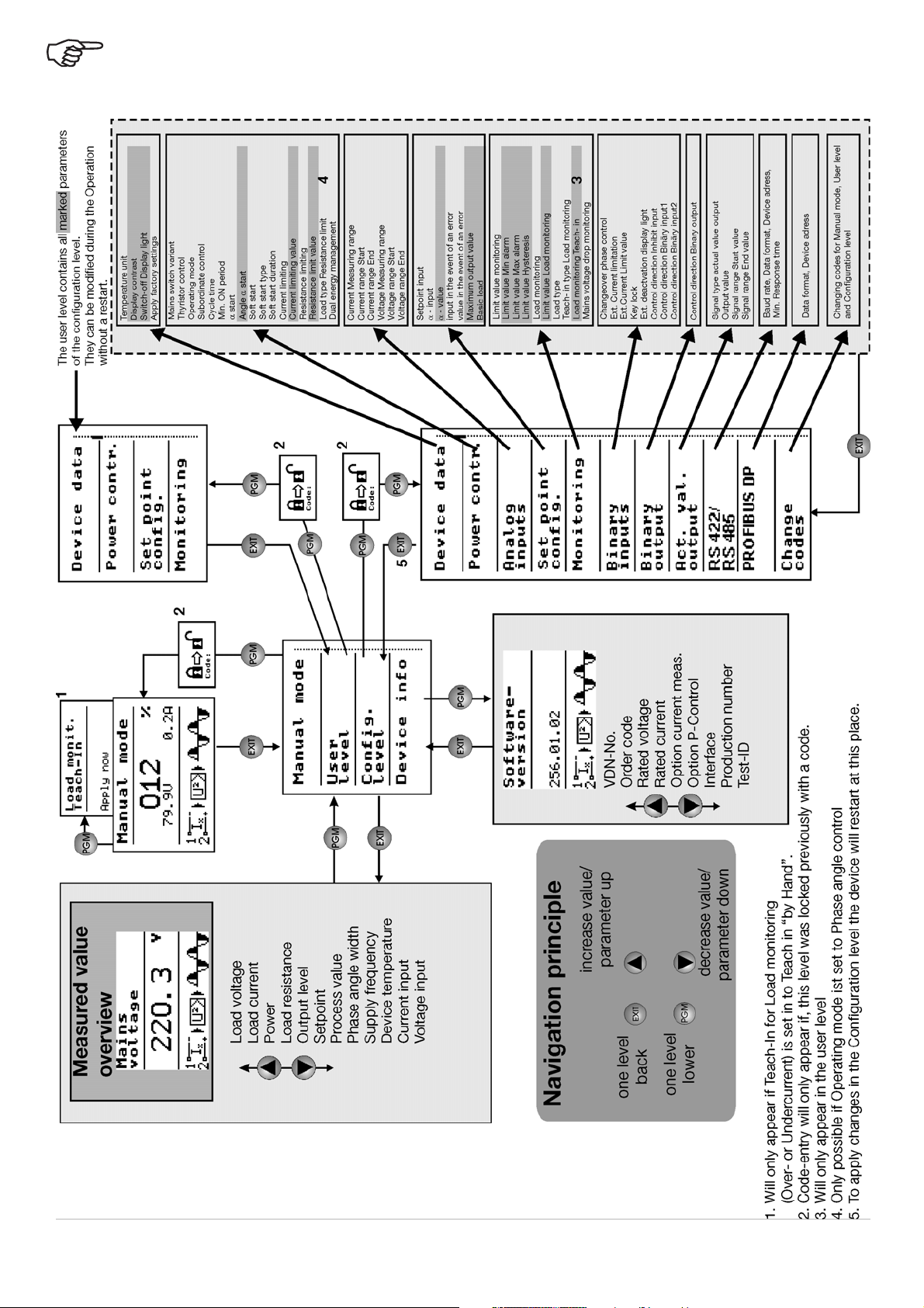
All parameter settings are described in detail in the chapter "Configuration".
This operating overview shows all possible parameters of the device series.
Depending on the order specifications or current configuration, any parameters that are not required are hidden.
Page 3

Inhalt
1 Introduction..................................................................................5
1.1 Preface ........................................................................................................ 5
1.2 Typographical conventions ....................................................................... 6
1.2.1 Warning symbols ................................................................................................. 6
1.2.2 Note signs ............................................................................................................ 7
1.2.3 Performing an action ........................................................................................... 7
1.2.4 Representation .................................................................................................... 7
1.3 Order details ............................................................................................... 8
1.3.1 Scope of delivery ................................................................................................. 9
1.3.2 Accessories ......................................................................................................... 9
1.3.3 General accessories ............................................................................................ 9
1.4 Brief description ....................................................................................... 10
1.5 Standards, approvals, and conformity ................................................... 11
2 Installation..................................................................................13
2.1 Important installation notes .................................................................... 13
2.1.1 Ambient conditions ........................................................................................... 14
2.1.2 Filtering and interference suppression ............................................................ 15
2.1.3 Permissible load current depending
on the ambient temperature and the installation height ................................ 15
2.1.4 Wall mounting with screws (ex works) ............................................................ 17
2.1.5 Mounting on DIN rail (accessories) .................................................................. 20
2.2 Dimensions ............................................................................................... 21
2.2.1 Type 709061/X-0X-020-XXX-XXX-XX-25X ....................................................... 21
2.2.2 Type 709061/X-0X-032-XXX-XXX-XX-25X ....................................................... 21
2.2.3 Type 709061/X-0X-050-XXX-XXX-XX-25X ....................................................... 22
2.2.4 Type 709061/X-0X-100-XXX-XXX-XX-25X ....................................................... 22
2.2.5 Type 709061/X-0X-150-XXX-XXX-XX-25X
Type 709061/X-0X-200-XXX-XXX-XX-25X ....................................................... 23
2.2.6 Type 709061/X-0X-250-XXX-XXX-XX-25X ...................................................... 24
2.2.7 Clearances (all types) ........................................................................................ 24
3 Electrical connection ................................................................25
3.1 Plug-in screw terminals ........................................................................... 25
2012-12-01/00531796 [Thyristor Leistungsschalter TYA201] 1
Page 4

Inhalt
3.1.1 Type 709061/X-0X-20-XXX-XXX-XX-25X ......................................................... 25
3.2 Cable lugs and plug-in screw terminals ................................................ 26
3.2.1 Type 709061/X-0X-032-XXX-XXX-XX-25X ....................................................... 26
3.2.2 Type 709061/X-0X-050-XXX-XXX-XX-25X ....................................................... 27
3.2.3 Type 709061/X-0X-100-XXX-XXX-XX-25X ....................................................... 28
3.2.4 Type 709061/X-0X-150-XXX-XXX-XX-25X
Type 709061/X-0X-200-XXX-XXX-XX-25X ....................................................... 29
3.2.5 Type 709061/X-0X-250-XXX-XXX-XX-25X ....................................................... 30
3.3 Connection diagram ................................................................................ 32
3.3.1 Single-phase operation: phase / N .................................................................. 34
3.3.2 Single-phase operation: phase / phase ........................................................... 35
3.3.3 Star connection with accessible star point (N) ............................................... 36
3.3.4 Open delta connection (six wire connection) ................................................. 37
3.3.5 Free-running economy circuit with purely resistive loads ............................. 38
3.3.6 Master-slave three-phase current economy circuit for resistive loads in star,
delta connection, or transformer loads (resistive-inductive) ........................ 39
4 Operation....................................................................................41
4.1 Display after switching on the device .................................................... 41
4.1.1 Display and control elements ........................................................................... 41
4.1.2 Displaying measured values ............................................................................. 42
4.1.3 Meaning of the displayed measured values .................................................... 43
4.1.4 Display in the configuration level ..................................................................... 44
4.1.5 Display of error messages and special states ................................................ 45
4.2 Operator level ........................................................................................... 46
4.2.1 Device data ........................................................................................................ 46
4.2.2 Power controller ................................................................................................ 46
4.2.3 Setpoint value configuration ............................................................................ 47
4.2.4 Monitoring .......................................................................................................... 48
5 Configuration .............................................................................51
5.1 Configuration level ................................................................................... 51
5.1.1 Device data ........................................................................................................ 52
5.1.2 Power controller ................................................................................................ 52
5.1.3 Analog inputs ..................................................................................................... 58
2 2012-12-01/00531796 [Thyristor Leistungsschalter TYA201]
Page 5

Inhalt
5.1.4 Setpoint value configuration ............................................................................ 59
5.1.5 Monitoring .......................................................................................................... 61
5.1.6 Binary inputs ...................................................................................................... 63
5.1.7 Binary output ...................................................................................................... 65
5.1.8 Actual value output ............................................................................................ 66
5.1.9 RS422/485 .......................................................................................................... 66
5.1.10 PROFIBUS-DP .................................................................................................... 67
5.1.11 Changing codes ................................................................................................. 67
5.2 Configuration example ............................................................................ 68
6 Special device functions...........................................................69
6.1 Detection of load faults ........................................................................... 69
6.1.1 Teach-in .............................................................................................................. 71
6.2 Manual mode ............................................................................................ 72
6.2.1 Default setpoint value in manual mode ........................................................... 72
6.2.2 Configuring the teach-in (prerequisite for teach-in in manual mode) .......... 72
6.2.3 Performing teach-in in manual mode .............................................................. 73
6.3 Default setpoint value via potentiometer .............................................. 74
6.4 Dual energy management ....................................................................... 74
6.5 Subordinate control ................................................................................. 76
6.5.1 Closed control loop without subordinate control ........................................... 76
6.5.2 Closed control loop with subordinate control ................................................ 77
6.6 Resistance limitation (R control) ............................................................ 82
6.7 Current limiting ........................................................................................ 83
6.8 α start ........................................................................................................ 84
6.9 Monitoring of the supply voltage drop ................................................... 84
6.10 Firing-pulse inhibit ................................................................................... 84
6.11 SCR control logic (switch) ....................................................................... 85
7 Setup program...........................................................................87
7.1 Hardware .................................................................................................. 87
7.2 Compatible operating systems ............................................................... 87
7.3 Installation ................................................................................................ 88
2012-12-01/00531796 [Thyristor Leistungsschalter TYA201] 3
Page 6

Inhalt
7.4 Program start ........................................................................................... 90
7.5 Forgotten the code? ................................................................................ 91
7.6 Changing the language of the device texts ........................................... 92
8 Fault messages and alarms......................................................93
8.1 Binary signal for collective fault ............................................................. 97
8.2 Replacing a defective semi-conductor fuse ......................................... 98
8.2.1 Accessories: semi-conductor fuses ................................................................ 99
8.2.2 Semi-conductor fuses type 709061/X-0X-20... ............................................... 99
8.2.3 Semi-conductor fuses type 709061/X-0X-32... ............................................. 100
9 What to do, if ...........................................................................103
10 Technical data..........................................................................105
10.1 Voltage supply, load current ................................................................. 105
10.2 Electrical isolation ................................................................................. 105
10.3 Analog inputs ......................................................................................... 106
10.4 Analog output (actual value output) ..................................................... 106
10.4.1 Display and measuring accuracy ................................................................... 106
10.5 Binary inputs ........................................................................................... 106
10.6 Binary output (fault signal output) ........................................................ 106
10.7 General characteristic data .................................................................. 107
10.8 Approvals/approval marks .................................................................... 109
4 2012-12-01/00531796 [Thyristor Leistungsschalter TYA201]
Page 7

1.1 Preface
1 Introduction
Please read this operating manual before starting up the device.
B
This operating manual is valid from device software version [256.01.05].
Keep the operating manual in a place that is accessible to all users at all times.
Your comments are appreciated and may assist us in improving this operating
manual.
Phone: +49 661 6003-727
Fax: +49 661 6003-508
The power controller produces the power that is needed at the analog input or
in manual mode. Safety systems independent of the power controller must be
installed that safely switch off the following heating process in the event of excess temperatures.
The power controller may only be operated using original JUMO semi-conductor fuses.
In the event of replacement, please check that the correct replacement part
has been used.
All necessary settings are described in this operating manual. Manipulations
not described in the operating manual or expressly forbidden will jeopardize
your warranty rights.
If you have any problems, please contact the nearest subsidiary or the head
office.
Service hotline For technical questions
Phone support in Germany:
Phone: +49 661 6003-9135
Fax: +49 661 6003-881899
E-mail: service@jumo.net
Austria:
Phone: +43 1 610610
Fax: +43 1 6106140
E-mail: info@jumo.at
Switzerland:
Phone: +41 1 928 24 44
Fax: +41 1 928 24 48
E-mail: info@jumo.ch
2012-12-01/00561071 [SCR Power Controller TYA201] 5
Page 8
1 Introduction
E
V
E
When accessing the inner parts of the device and returning device modules,
assemblies, or components, please observe the regulations according to DIN
EN 61340-5-1 and DIN EN 61340-5-2 "Protection of electrostatic sensitive devices from electrostatic phenomena". Use only ESD packaging for transport.
Please note that we cannot accept any liability for damage caused by ESD
(electrostatic discharge).
ESD=Electro Static Discharge
1.2 Typographical conventions
1.2.1 Warning symbols
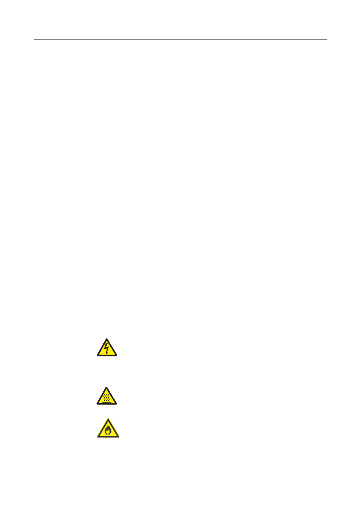
Caution
This symbol is used when danger to personnel may occur if the instructions are disregarded or not followed correctly.
Caution
ESD
Dangerous voltage
Hot
surface,
fire hazard
This symbol is used when damage to devices or data may occur
if the instructions are disregarded or not followed correctly.
This symbol is used if precautions must be taken when handling
components liable to damage through electrostatic discharge.
This symbol is used if dangerous voltages will cause an electric shock
if contact with live parts is made.
This symbol is used if burns can result from touching a hot surface.
Do not install any heat-sensitive components and devices close to
the power controller.
6 2012-12-01/00561071 [SCR Power Switch TYA201]
Page 9

1.2.2 Note signs
v
B
Note:
Reference
Footnote
abc
1 Introduction
This symbol is used to indicate particularly important information.
This symbol refers to further information in other manuals, chapters, or sections.
1
Footnotes are remarks that refer to specific parts of the text. Footnotes consist of two parts:
An identification marking in the text, and the footnote text itself.
The identification markings in the text are arranged as sequential
superscript numbers.
1.2.3 Performing an action
Action
instruction
Vital text
Command sequence
h Plug in the
connector
Config. level r Power controller r
Operating mode
1.2.4 Representation
This symbol indicates that an action to be performed is described. The individual steps are marked by this asterisk.
This text contains important information, and it is vital that you
read it before proceeding.
Small arrows between words are intended
to facilitate faster location of parameters in
the configuration level.
Keys
Keys are displayed as symbols or text.
Key combinations are represented by a plus sign.
2012-12-01/00561071 [SCR Power Controller TYA201] 7
Page 10
1 Introduction
a
UL approval in preparation
b
Load voltage = voltage supply for control electronics
Important information:
Subordinate control loop U
2
, code 100: voltage control
Subordinate control loop I
2
, code 010: enables partial load failure detection, dual energy management, and current limiting
Subordinate control loop P, code 001: enables partial load failure detection, dual energy management, current limiting, free-running
economy circuit, and R control
At a load current of 250 A, observe voltage supply for fan!
v Chapter 3.2.5 "Type 709061/X-0X-250-XXX-XXX-XX-25X"
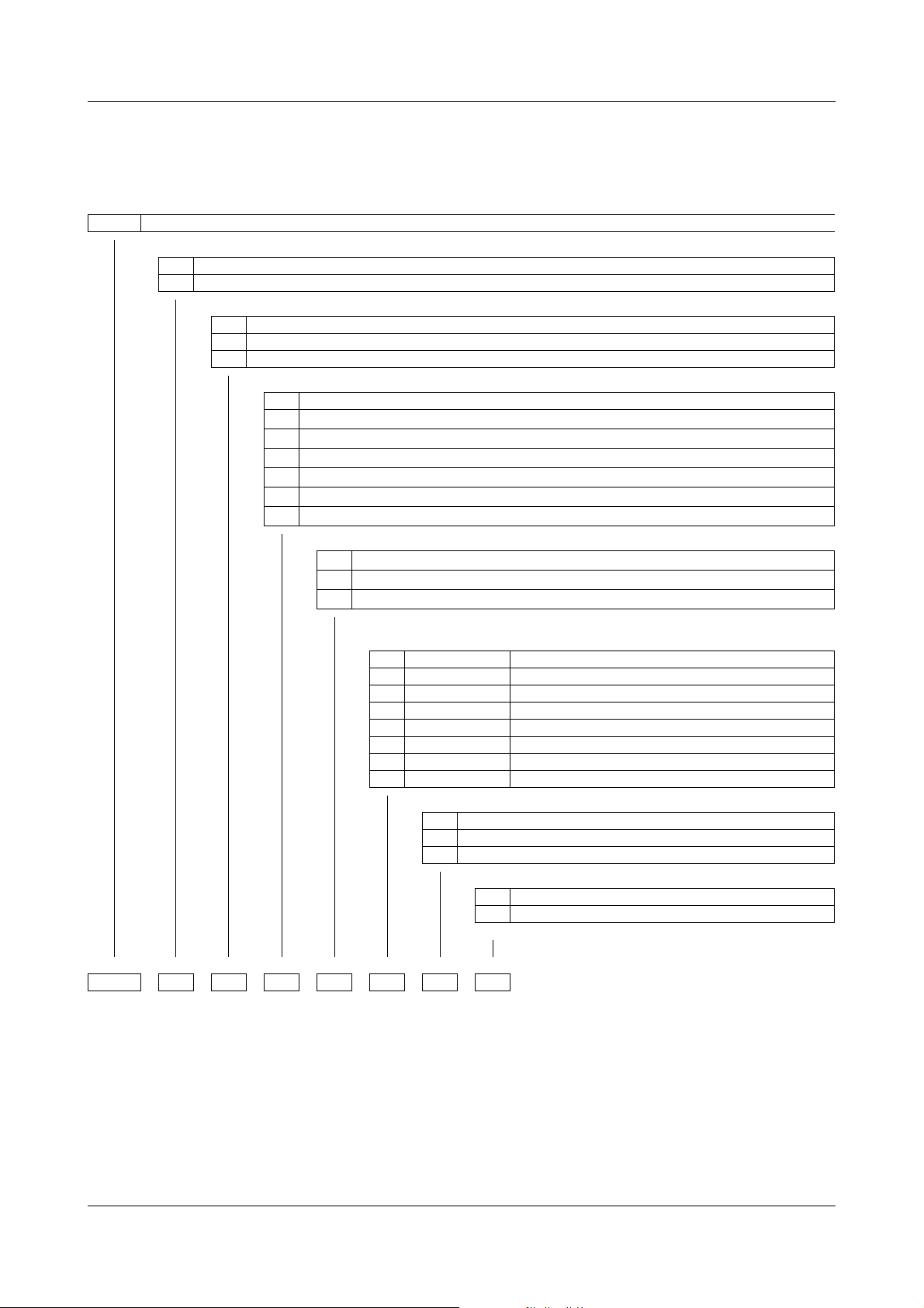
1.3 Order details
The nameplate is affixed to the right-hand side of the case.
(1) Basic type
709061 TYA 201 single-phase SCR power controller
(2) Version
8 Standard with factory settings
9 Customer-specific programming according to specifications
(3) National language of display texts
01 German (set at factory)
02 English
03 French
(4) Load current
020 AC 20 A
032 AC 32 A
050 AC 50 A
100 AC 100 A
150 AC 150 A
200 AC 200 A
250 AC 250 A
(5) Subordinate control loop
100 U, U
010 I, I
001 P (can be set to I, I
a
2
2
(can be set to U, U2)
2
or U, U2)
(6) Load voltage
024 AC24V -20to+15%, 45to63Hz
042 AC42V -20to+15%, 45to63Hz
115 AC 115 V -20 to +15 %, 45 to 63 Hz
230 AC 230 V -20 to +15 %, 45 to 63 Hz
265 AC 265 V -20 to +15 %, 45 to 63 Hz
400 AC 400 V -20 to +15 %, 45 to 63 Hz
460 AC 460 V -20 to +15 %, 45 to 63 Hz
500 AC 500 V -20 to +15 %, 45 to 63 Hz
00 None
54 RS485/422
64 PROFIBUS-DP
(1) (2) (3) (4) (5) (6) (7) (8)
/-----/Order code
709061 / 8 - 01 - 100 - 100 - 400 - 00 / 252 Order example
b
(7) Interface
(8) Extra codes
252
Relay (changeover contact) 3 A
257 Optocoupler
8 2012-12-01/00561071 [SCR Power Switch TYA201]
Page 11
1.3.1 Scope of delivery
1 operating manual B709061.0
1 SCR power controller in the version ordered
1.3.2 Accessories
Article Part no.
Setup program 709061 (TYA 201) 00544869
USB cable A-connector B-connector 3 m 00506252
Mounting set for DIN rail installation:
Type 709061/X-01-20... 00555169
Type 709061/X-01-32... 00555526
1.3.3 General accessories
1 Introduction
Semi-conductor
fuses
A semi-conductor fuse is fitted in the power controller to protect the SCR
module. The "LED Fuse" is lit red in the event of a fault.
v Chapter 8.2 "Replacing a defective semi-conductor fuse"
Article Load current
I
= I
Super fast semi-conductor fuse 40 A I
Super fast semi-conductor fuse 80 A I
Super fast semi-conductor fuse 80 A I
Super fast semi-conductor fuse 160 A I
Super fast semi-conductor fuse 350 A I
Super fast semi-conductor fuse 550 A I
Super fast semi-conductor fuse 550 A I
nom.
= 20 A 00513108
N
= 32 A 00068011
N
= 50 A 00068011
N
= 100 A 00081801
N
= 150 A 00083318
N
= 200 A 00371964
N
= 250 A 00371964
N
N
Part no.
2012-12-01/00561071 [SCR Power Controller TYA201] 9
Page 12

1 Introduction
1.4 Brief description
Device The JUMO TYA 201 represents the consistent development of the JUMO pow-
er controller technology. The microprocessor-controlled power controller
shows all parameters on a display with background lighting and is operated
using 4 keys at the front.
Application SCR power controllers are used where larger resistive and inductive loads
have to be switched (e.g. in industrial kiln construction and plastics processing). The SCR power controller consists of two SCRs connected in anti-parallel, the insulted cooling body, and the control electronics.
Installation All SCR power controllers up to a load current of 32 A can be either clipped to
a 35 mm mounting rail or fitted to the wall on a mounting plate. Devices with a
load current greater than 32 A can only be mounted on the wall.
Operating
modes
Load types All resistive loads through to inductive loads are permitted.
Subordinate
control loop
Standards The SCR power controllers are in accordance with VDE 0160 5.5.1.3 (5/88)
The keypad or setup program is used to select the phase angle control operating mode with adjustable current limiting, burst-firing mode, or half-wave
mode.
In burst-firing mode, the phase angle of the first half-wave can be cut so that
transformer loads can also be operated. In phase control mode, the phase angle specified by the controller is slowly reduced, starting from 180 degrees, in
order to avoid high starting or inrush currents (soft start).
It is possible to specify a base load or, depending on the device type, set current limiting or resistance limitation for the load.
In the case of inductive loads, the nominal inductance may not exceed 1.2
Tesla (at grid overvoltage of 1.45 T).
Depending on the device type, U, U
dinate control loops. Variations in the mains voltage therefore have no effect
on the control-loop regulation during operation.
and VDE 0106 Part 100 (3/83). Grounding is required in conformity with the
regulations of the responsible energy utility company.
2
, I, I2, or P control are available as subor-
Advantages - Teach-in function for the detection of partial load failure
- Network load optimization through dual energy management
- Transmission of the setup data is possible even without voltage supply to
the device (power supply via USB port)
10 2012-12-01/00561071 [SCR Power Switch TYA201]
Page 13
1.5 Standards, approvals, and conformity
Test basis for the device properties is the Low Voltage Directive DIN EN 50178.
Test basis for the EMC Directive is DIN EN 61326-1.
Standard
Electrical connection DIN VDE 0100
Protection type IP20 panel-mount-
ing devices
Climatic ambient conditions Class 3K3
Air temperature and rel. humidity DIN EN 60721-3-3
Storage temperature Class 1K5 DIN EN 60721-3-1
Operating conditions
Pollution degree
Overvoltage category
Test voltages DIN EN 50178
Residual current circuit breaker DIN EN 50178
Electromagnetic compatibility
Emitted interference
Interference resistance
Mechanical tests:
Vibration test 3M2
Toppling test Class 2M1
Labels, identification marking DIN EN 50178, DIN EN 61010-1
DIN EN 60529
DIN EN 50178
2
III
DIN EN 61326-1
Class A- For industrial applications only
Industrial requirements
DIN EN 60068-2-6, DIN EN 60721-3-3
DIN EN 60068-2-31, DIN EN 60721-3-2
1 Introduction
Approvals Standard
submitted UL 508 (Category NRNT)
C22.2 NO. 14-10 Industrial Control Equipment
(Category NRNT7)
Can be used for current circuits with a short-circuit current capacity of
≤ 100 kA (the admissible supply voltage must correspond to the nominal voltage of
the SCR power controller).
For system protection, a fuse up to Class RK5 may be used.
CE conformity Low Voltage Directives 2006/95/EC
Marking Directives 93/68EEC
EMC Directives 2004/108/EC
Conformity Standard
RoHs 2002 / 95 EC
2012-12-01/00561071 [SCR Power Controller TYA201] 11
Page 14

1 Introduction
12 2012-12-01/00561071 [SCR Power Switch TYA201]
Page 15

2.1 Important installation notes
V
2 Installation
Safety regulations
Fuse protection k Fuse protection of the supply lead in accordance with the VDE regulations
k The choice of cable material, the installation, and the electrical connection
of the device must conform to the requirements of VDE 0100 "Regulations
on the Installation of Power Circuits with Nominal Voltages below AC
1000 V" or the appropriate local regulations.
k The electrical connection must only be carried out by qualified personnel.
k An isolating switch should be wired between the voltage supply and the de-
vice to be able to disconnect the device from the voltage supply on all
poles prior to starting internal work.
k Inside the device, safety clearances meet the requirements for double insu-
lation.
When fitting the connecting cable, ensure that the cables are fitted according to regulations and that the safety clearances are maintained.
must be installed when wiring the voltage supply in the power section. The
supply protection can also be achieved by a circuit-breaker in the supply
lead. The circuit-breaker must correspond to the power consumption of the
power controller.
k For UL application, it must be ensured that the fuse for the supply protec-
tion of the control electronics is between 2 A and a maximum of 5 A. This
also applies to the fan connection.
k To protect the power controller in the event of an earth fault, a semi-con-
ductor fuse is installed. In the event of a defect, these may only be replaced
with original JUMO semi-conductor fuses.
v Chapter 8.2 "Replacing a defective semi-conductor fuse"
Wiring Supply voltage and control cables are to be wired isolated from one another.
For supply protection, fuses (e.g. 2 A Neozed) must also be installed in the
control circuit.
PE connection h A direct connection must be provided between the PE conductor of the
power controller and the PE conductor of the supply network. Connection
takes place at the PE connection terminal.
The cross section of the PE conductor must be at least as large as the cross
section of the voltage supply conductors to the power section. In the event
that the protective conductor is not a component of the supply lead or its encasement, the selected conductor cross section may not be less than
2.5 mm
conductor is not protected mechanically).
v See VDE 0100 Part 540
Check h That the data given on the nameplate (rated load voltage, load current) cor-
2
(for mechanical protection) or not less than 4 mm2 (if the protection
responds to the data for the system.
h That, if the economy circuit configuration is used, the rotary electrical field
has clockwise phasing.
2012-12-01/00561071 [SCR Power Controller TYA201] 13
Page 16

2 Installation
h That the configuration of the analog inputs, for example, corresponds to the
h The analog input for the default setpoint value in "Master-slave operation"
wiring.
only needs to be connected to the master. The slave receives its information via the patch cable.
However, the slave power controller can be disconnected separately by
means of its own inhibit input.
Load connection
Phasing The voltage supply of the control electronics and the load voltage
Control inputs The terminal strips for control connections (inputs and outputs) have been laid
h The electronic switch (2 anti-parallel SCRs) is located between the U1 and
U2 terminals.
h Load wiring and cables for control inputs should be routed separately, if
possible.
h Perform connection of supply voltage - SCR power controller - load in ac-
cordance with the wiring diagram and check.
must have the same phase.
out for safe isolation from the voltage supply (SELV). In order not to diminish
this safety isolation, all connected electrical circuits must also have safety isolation. The required auxiliary voltages must be safe extra-low voltages.
2.1.1 Ambient conditions
Incorrect use The device is not suitable for installation in potentially explosive atmospheres.
Mounting site The power controller must be installed in a fire-proof control cabinet.
The cabinet should be vibration-free, free from aggressive media, and free
from dust to prevent the ventilation slots from becoming blocked.
Climatic
conditions
Avoid additional
sources of heat
Power dissipation
- Relative humidity: 5 to 85 % no condensation (3K3 according to EN 60721)
- Ambient temperature range: 0 to 45 °C (3K3 according to EN 60721-3-3)
- Storage temperature range: -30 to 70 °C class 1K5
- Ensure that the ambient temperature at the installation site is not increased
by other sources of heat or heat accumulation.
- Do not mount the power controller too close to the heating process (kiln)
- Avoid direct sunlight.
Occurs as waste heat on the cooling body of the power controller and must be
dissipated at the mounting site (e.g. in the control cabinet) in accordance with
the climatic conditions.
14 2012-12-01/00561071 [SCR Power Controller TYA201]
Page 17
2.1.2 Filtering and interference suppression
45 50 60
75
20
200
T/°C
150
Load current in A
Reduction at a temperature of 45 °C:
2 %/kelvin
70 %
250
100
50
To prevent radio-frequency interference, such as occurs with a soft start in
phase angle control, electrical apparatus and systems must have interference
suppression implemented.
The control electronics of the SCR power controller correspond to the EMC requirements of EN 61326.
However, electrical modules such as SCR power controllers do not have any
purpose by themselves. They provide a function as part of a complete system
or installation.
Where applicable, the entire load circuit of the power controller must also have
suitable interference suppression filters fitted by the system provider.
There are a number of specialist companies that provide appropriate ranges of
filters to deal with any interference problems. Such filters are normally supplied as complete modules that are ready to be connected.
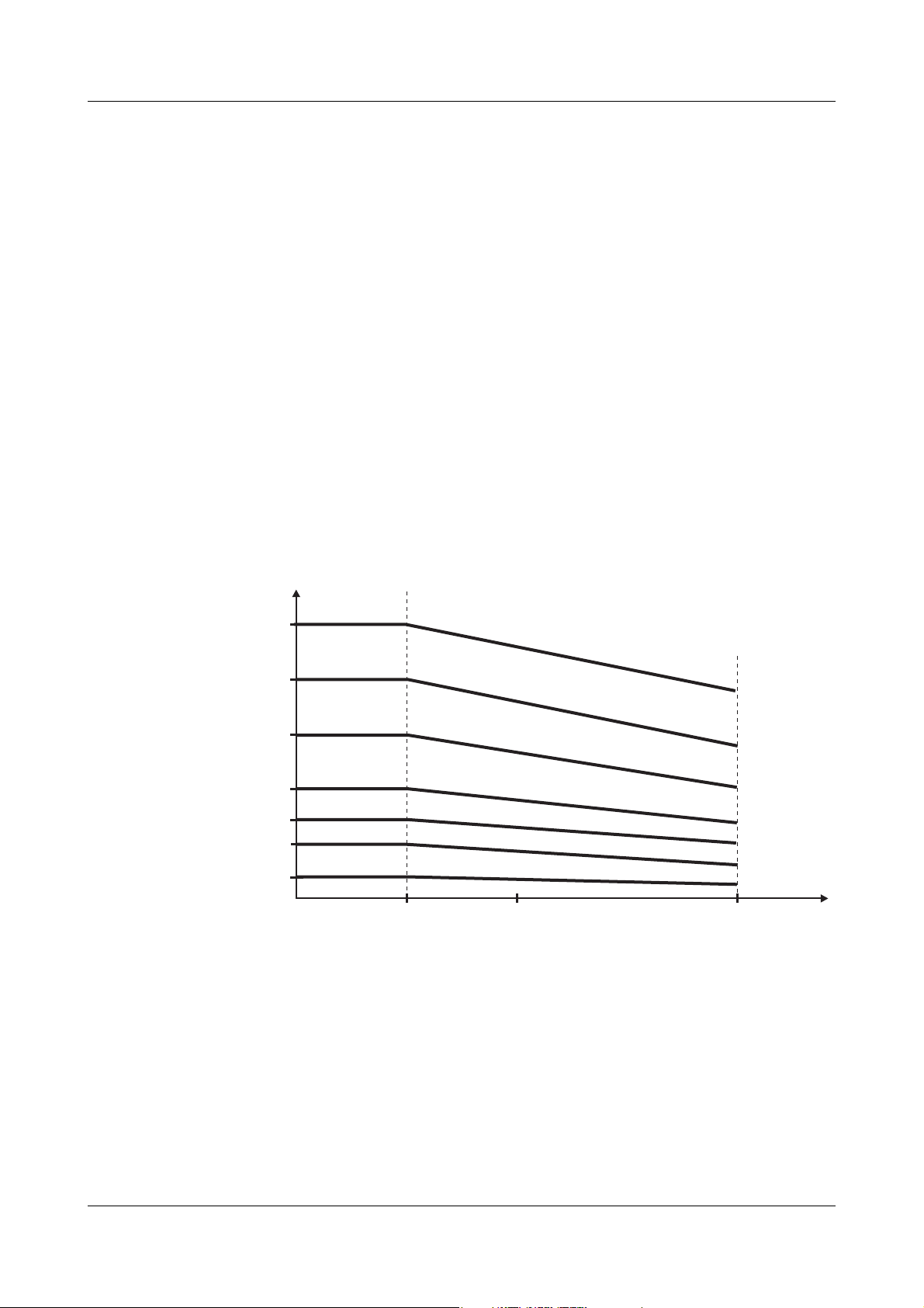
2.1.3 Permissible load current depending on the ambient temperature and the installation height
2 Installation
Ambient temperature
2012-12-01/00561071 [SCR Power Controller TYA201] 15
Page 18
2 Installation
Destruction through overheating:
In the event of operation over a long period at maximum load current, the cooling body and its environment heats up.
For this reason, at ambient temperatures above 45 °C, the maximum load current must be reduced as shown in the image, as the SCR module would otherwise be destroyed.
The device temperature shown on the display may not exceed 100 °C.
At a device temperature of > 100 °C, the message "Attention! High temperature" is displayed.
At a device temperature of > 105 °C, the output level is gradually decreased by
10 °C for each increase in temperature of one degree.
At a device temperature of > 115 °C, the power controller is switched off entirely.
v Chapter 8 "Fault messages and alarms"
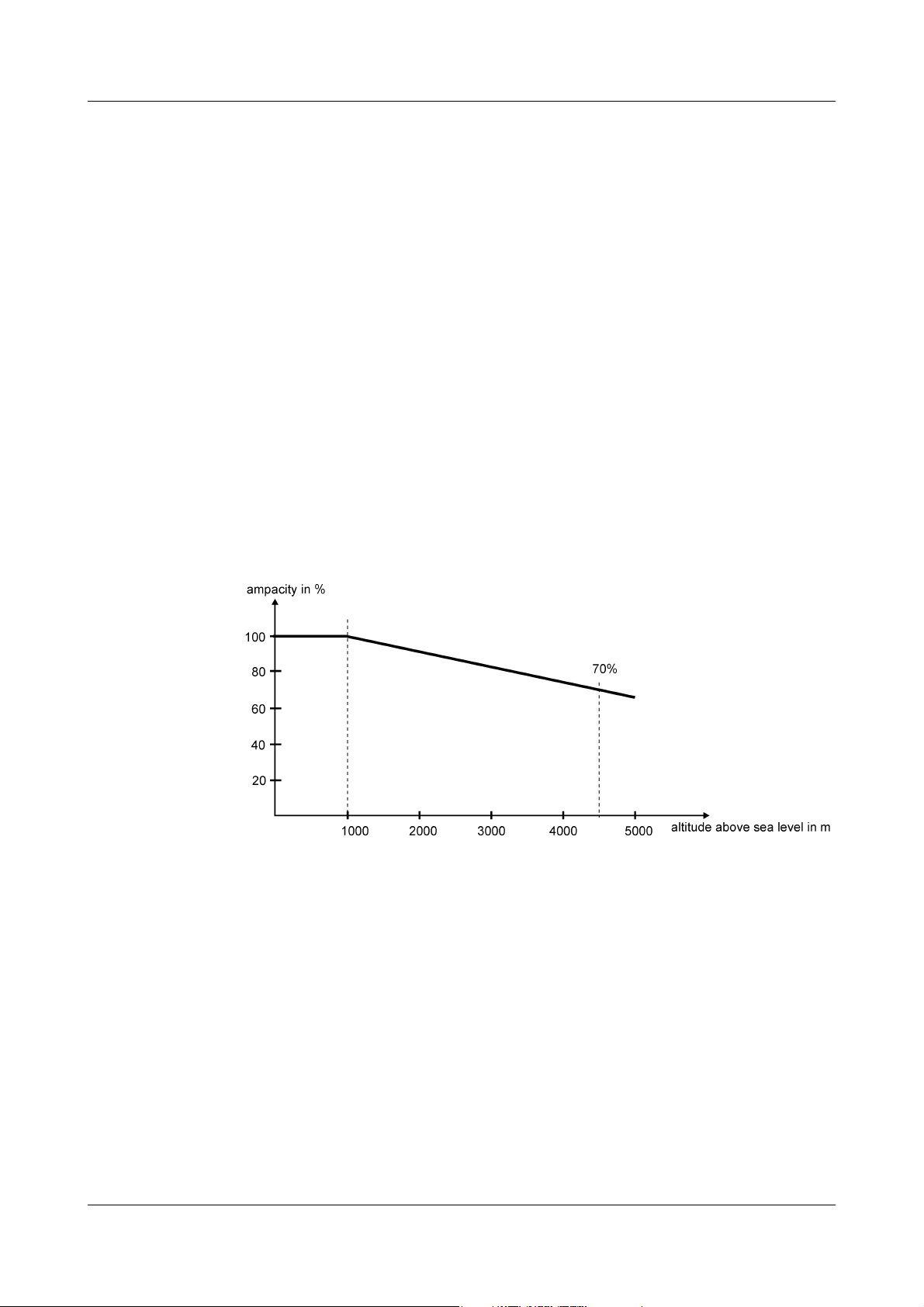
Installation
height
In the case of air cooling, it must be noted that the effectiveness of the cooling
is reduced the higher up the device is installed. As a result, the current carrying
capacity of the SCR power controller decreases with such a cooler as the installation height increases as shown in the image.
16 2012-12-01/00561071 [SCR Power Controller TYA201]
Page 19

2.1.4 Wall mounting with screws (ex works)
TYA201
20A
TYA201
32A
TYA201
50A
Power controllers with a load current between 20 and 50 A are affixed to a fireproof control cabinet wall with 2 screws. The left-hand hole is more easily accessible in the upper section.
Power controllers with a load current between 100 and 250 A are affixed with 4
screws.
2 Installation
2012-12-01/00561071 [SCR Power Controller TYA201] 17
Page 20
2 Installation
TYA201 100A
TYA201 150/200A
18 2012-12-01/00561071 [SCR Power Controller TYA201]
Page 21
2 Installation
TYA201 250A
2012-12-01/00561071 [SCR Power Controller TYA201] 19
Page 22
2 Installation
Hot
surface
The power controller heats up during operation to a maximum of
110 °C, depending on the load.
Ensure that the lamellae of the cooling body are vertically aligned to
allow the heat to be dissipated through natural convection.
Fire hazard:
Do not install any heat-sensitive components or devices close to the
power controller.
Integrated ventilator for 250 A power controller:
The intake air at the ventilation grid of the ventilator may not exceed a maximum supply air temperature of 35 °C. Ensure that the
inlet air for the integrated ventilators can be taken in from below
and escape at the top without obstruction!
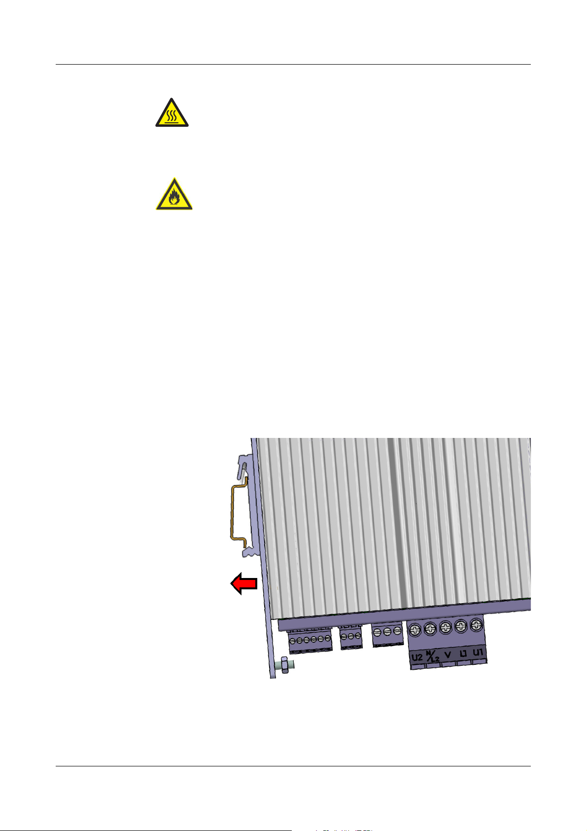
2.1.5 Mounting on DIN rail (accessories)
Power controllers up to 32 A can be affixed to a DIN rail using the corresponding accessories.
v Chapter 1.3.2 "Accessories"
h Hook the spring clip into the DIN rail from above
h Swivel the power controller downward until the lug engages with the DIN
rail with an audible click.
20 2012-12-01/00561071 [SCR Power Controller TYA201]
Page 23
2.2 Dimensions
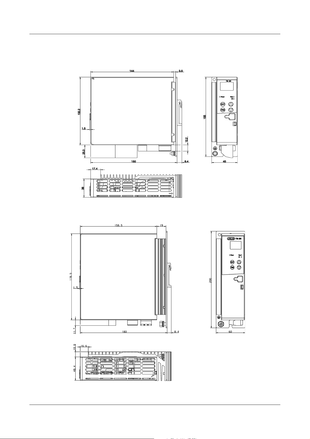
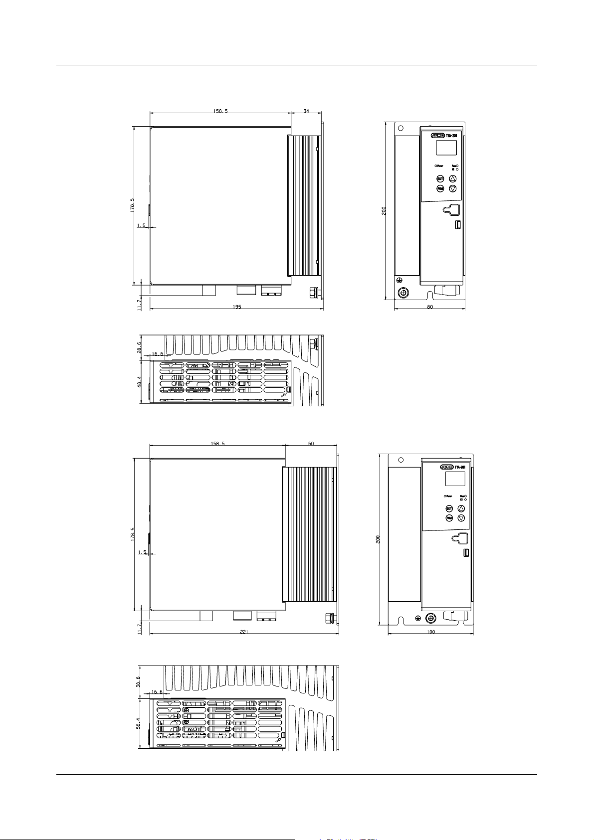
2.2.1 Type 709061/X-0X-020-XXX-XXX-XX-25X
2 Installation
2.2.2 Type 709061/X-0X-032-XXX-XXX-XX-25X
2012-12-01/00561071 [SCR Power Controller TYA201] 21
Page 24
2 Installation
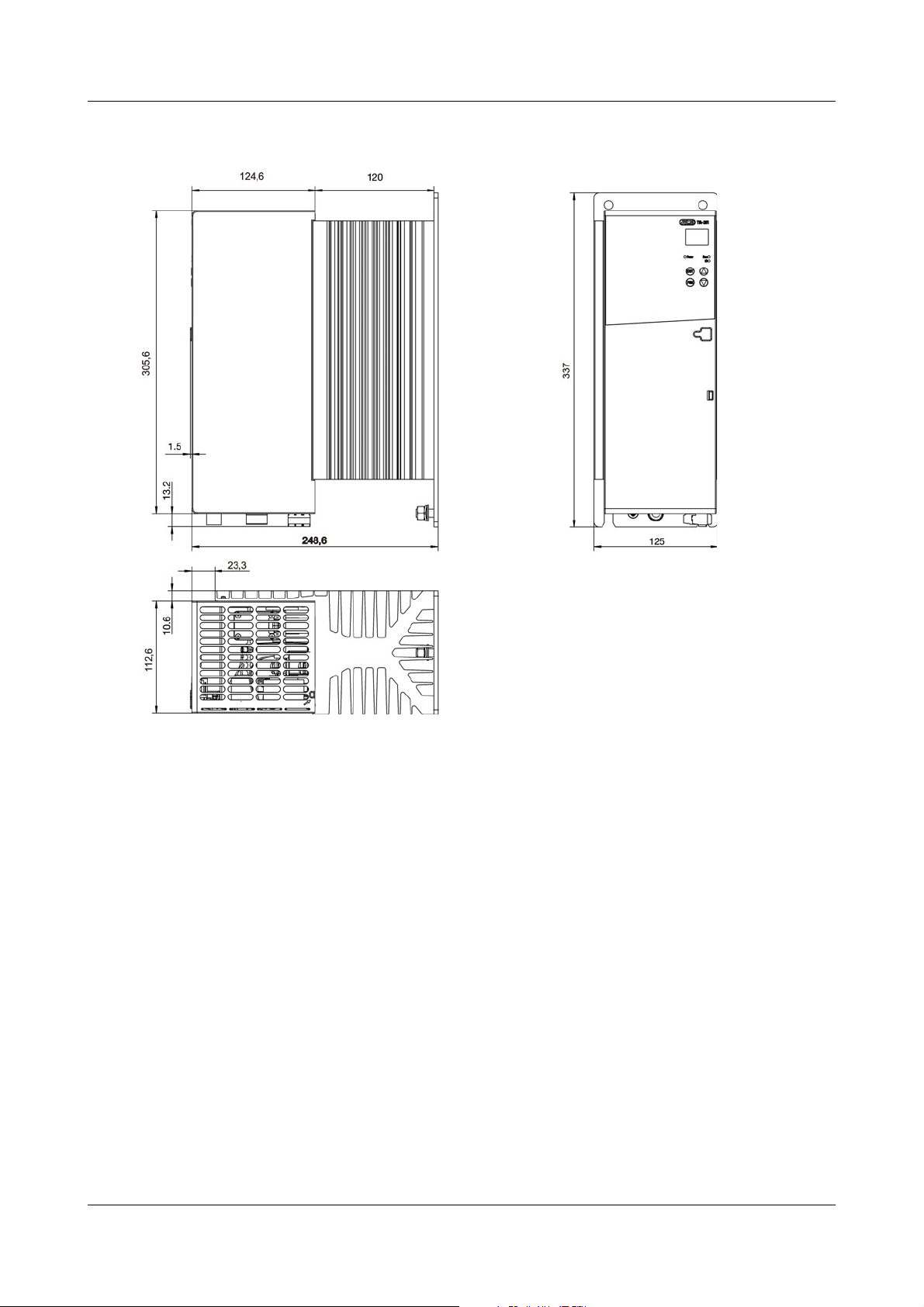
2.2.3 Type 709061/X-0X-050-XXX-XXX-XX-25X
2.2.4 Type 709061/X-0X-100-XXX-XXX-XX-25X
22 2012-12-01/00561071 [SCR Power Controller TYA201]
Page 25
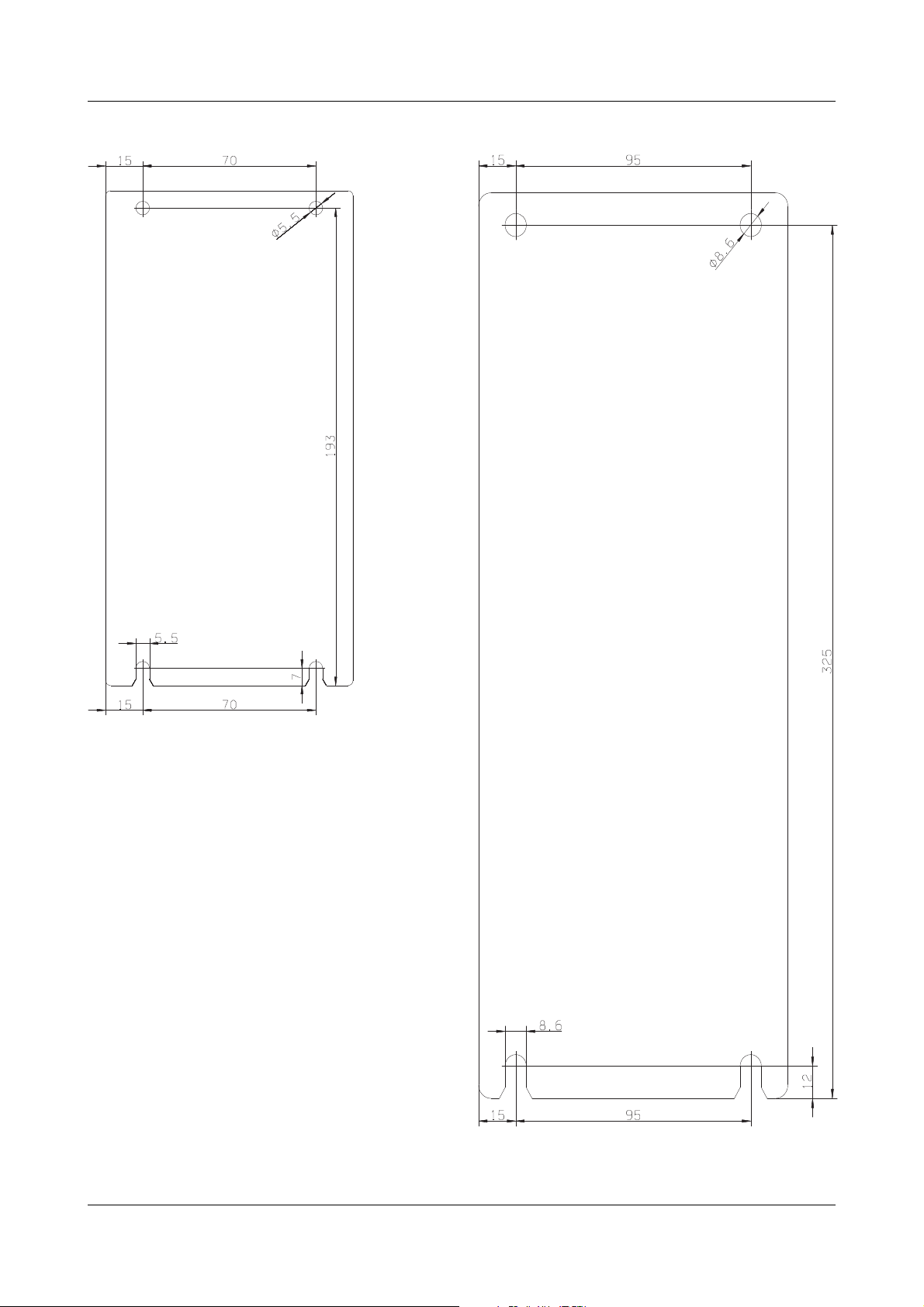
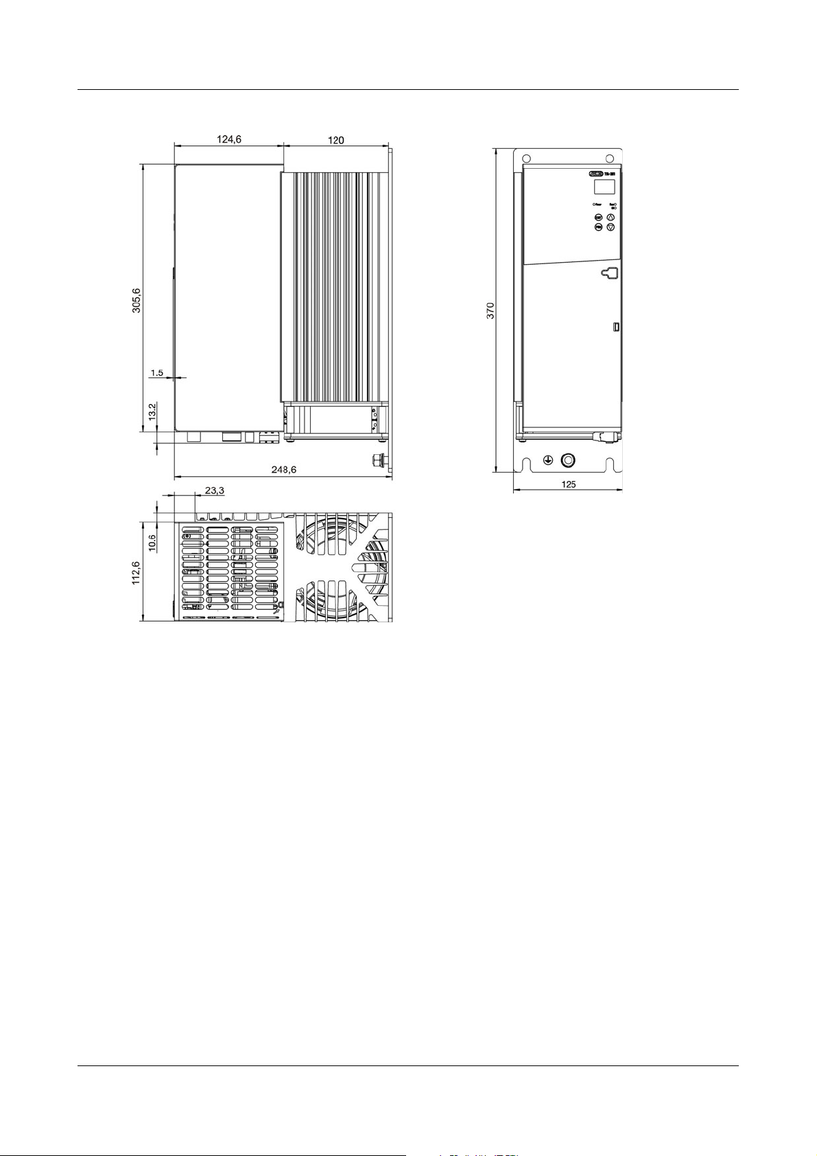
2.2.5 Type 709061/X-0X-150-XXX-XXX-XX-25X Type 709061/X-0X-200-XXX-XXX-XX-25X
2 Installation
2012-12-01/00561071 [SCR Power Controller TYA201] 23
Page 26
2 Installation
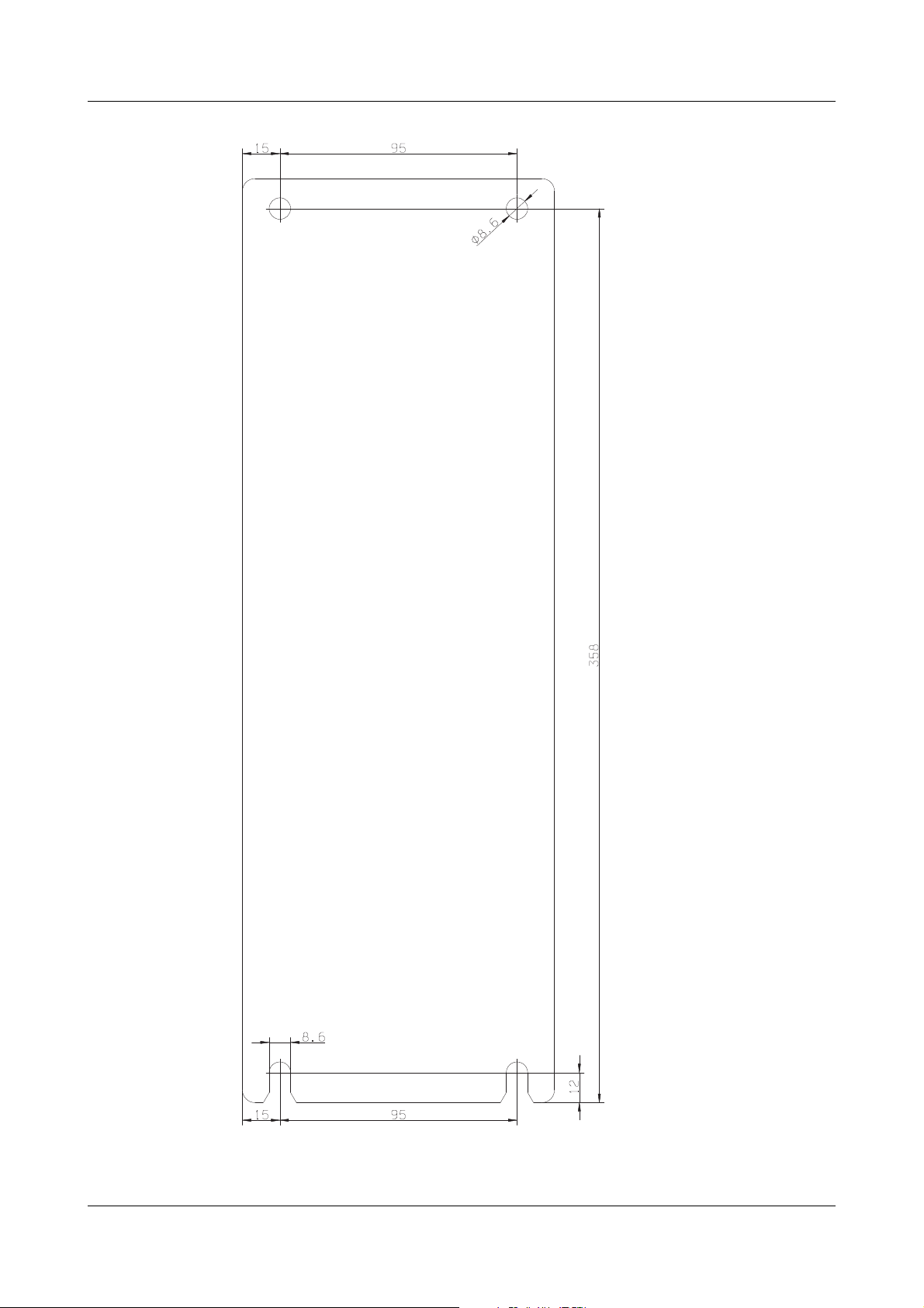
2.2.6 Type 709061/X-0X-250-XXX-XXX-XX-25X
2.2.7 Clearances (all types)
h Allow a clearance of 10 cm from the floor.
h Allow a clearance of 15 cm from the ceiling.
h When fitted next to each other, no spacing between the devices is required.
24 2012-12-01/00561071 [SCR Power Controller TYA201]
Page 27
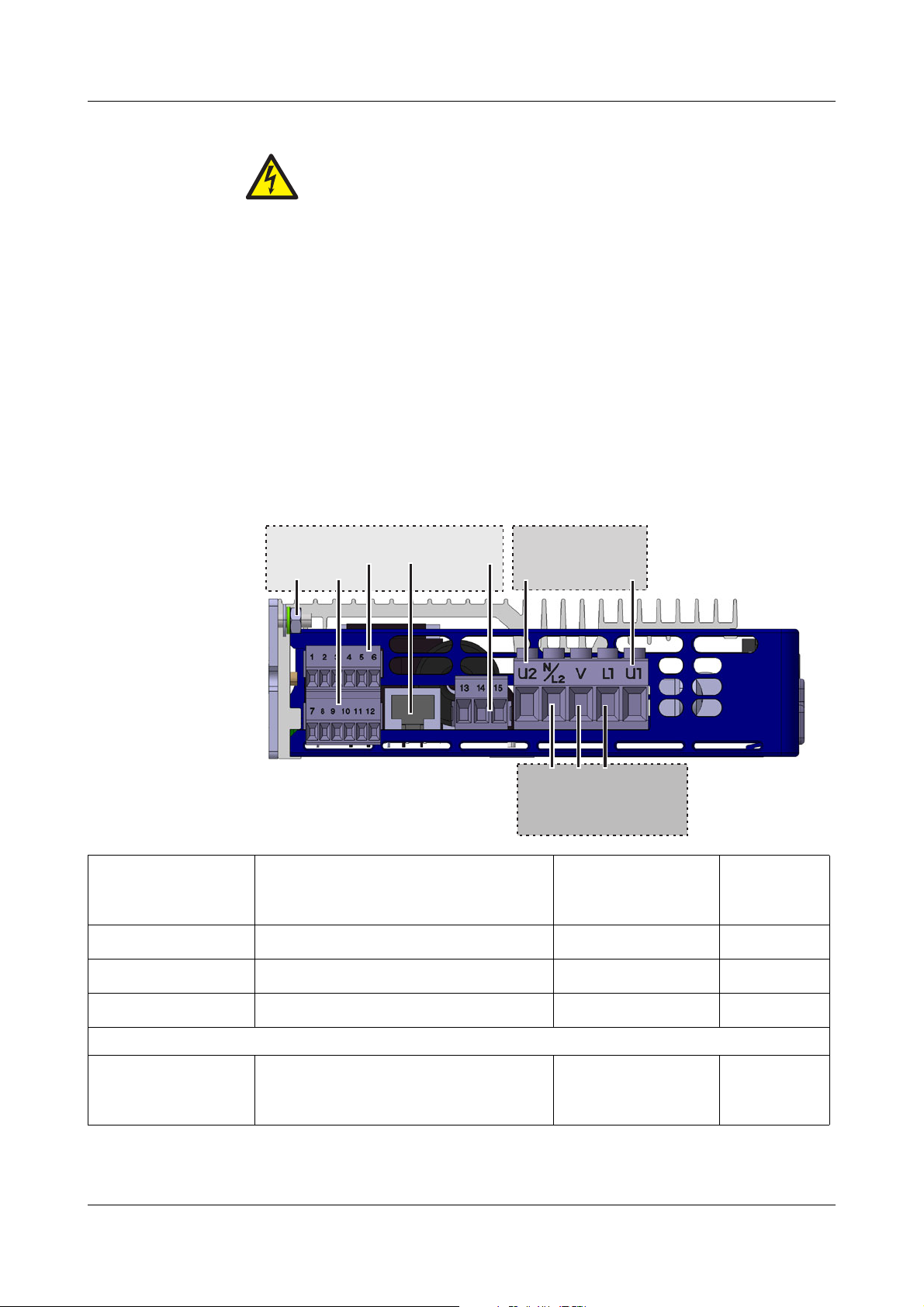
3 Electrical connection
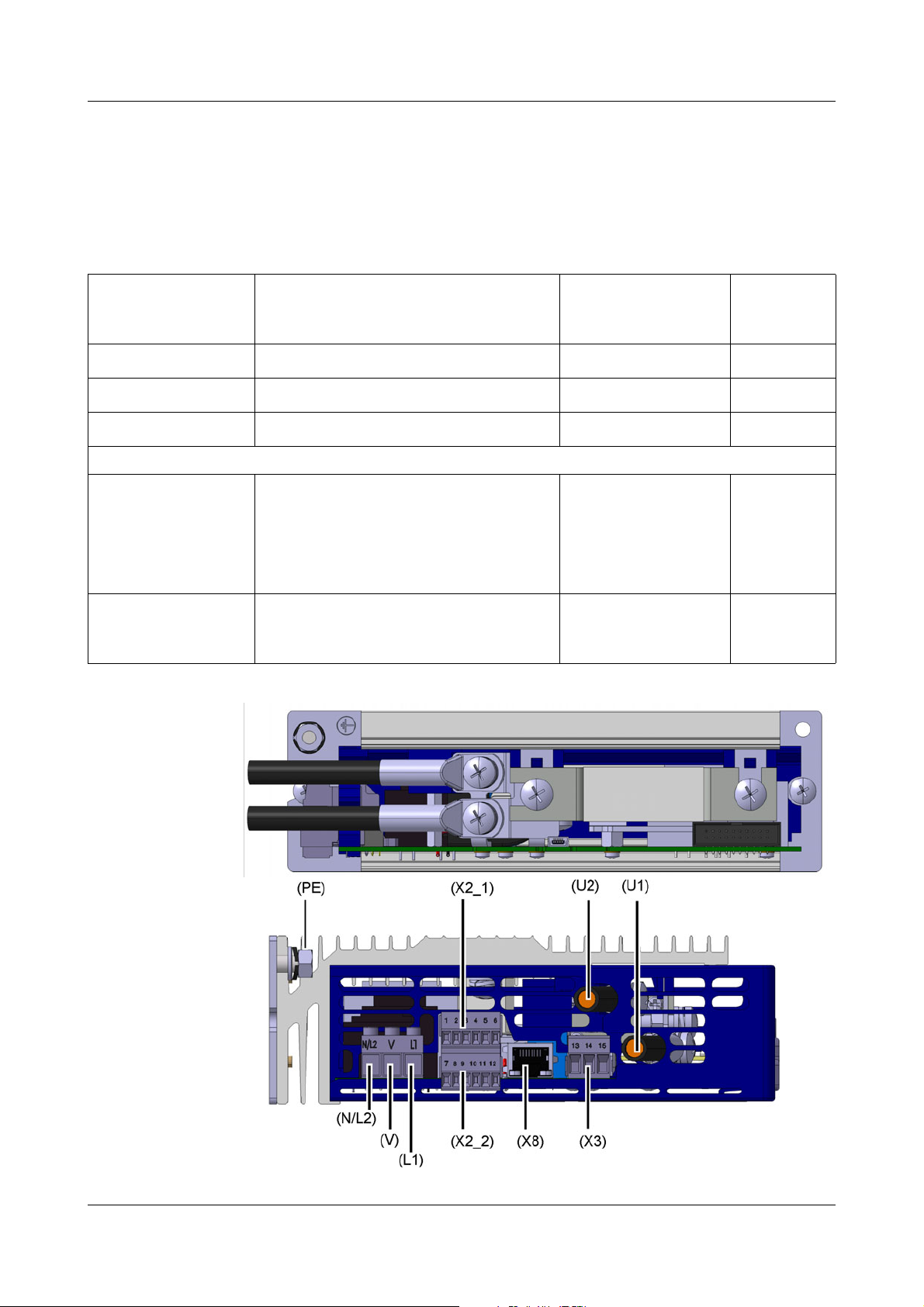
( 2)X2_
(X2_1) (X8) ( )X3
(U1)
(U2)
(N/L2)
(V)
(L1)
(PE)
Voltage supply
lectronicsControl e
Controlsection
Power section
Dangerous
voltage
h Disconnect the system from the voltage supply on all poles.
3.1 Plug-in screw terminals
Tools - Flat-blade screwdriver, blade width 2, 3, and 5 mm
- Ring or open-end wrench, width across flats 7, 10, 13 mm
3.1.1 Type 709061/X-0X-20-XXX-XXX-XX-25X
The device with a load current of 20 A is connected via plug-in screw terminals.
The electrical connection must only be carried out by qualified personnel! Dangerous voltages will cause an electric shock if contact
with live parts is made!
Terminal Version Conductor cross-
X2_1 and X2_2 Slotted screws, blade width 2 mm
X3 Slotted screws, blade width 3 mm
U2, N/L2, V, L1, U1 Slotted screws, blade width 5 mm
For applications according to UL, only 60 °C or 60 °C / 75 °C copper conductors may be used!
Ground terminal PE M4 setscrew with hexagon
2012-12-01/00561071 [SCR Power Controller TYA201] 25
nut
Width across flats 7 mm
section
0.2 to 1.5 mm
0.5 to 2.5 mm
0.5 to 6 mm
2
Cable lug with
hole: 4 mm
Maximum
tightening
torque
2
2
0.25 Nm
0.5 Nm
0.6 Nm
3Nm
Page 28
3 Electrical connection
3.2 Cable lugs and plug-in screw terminals
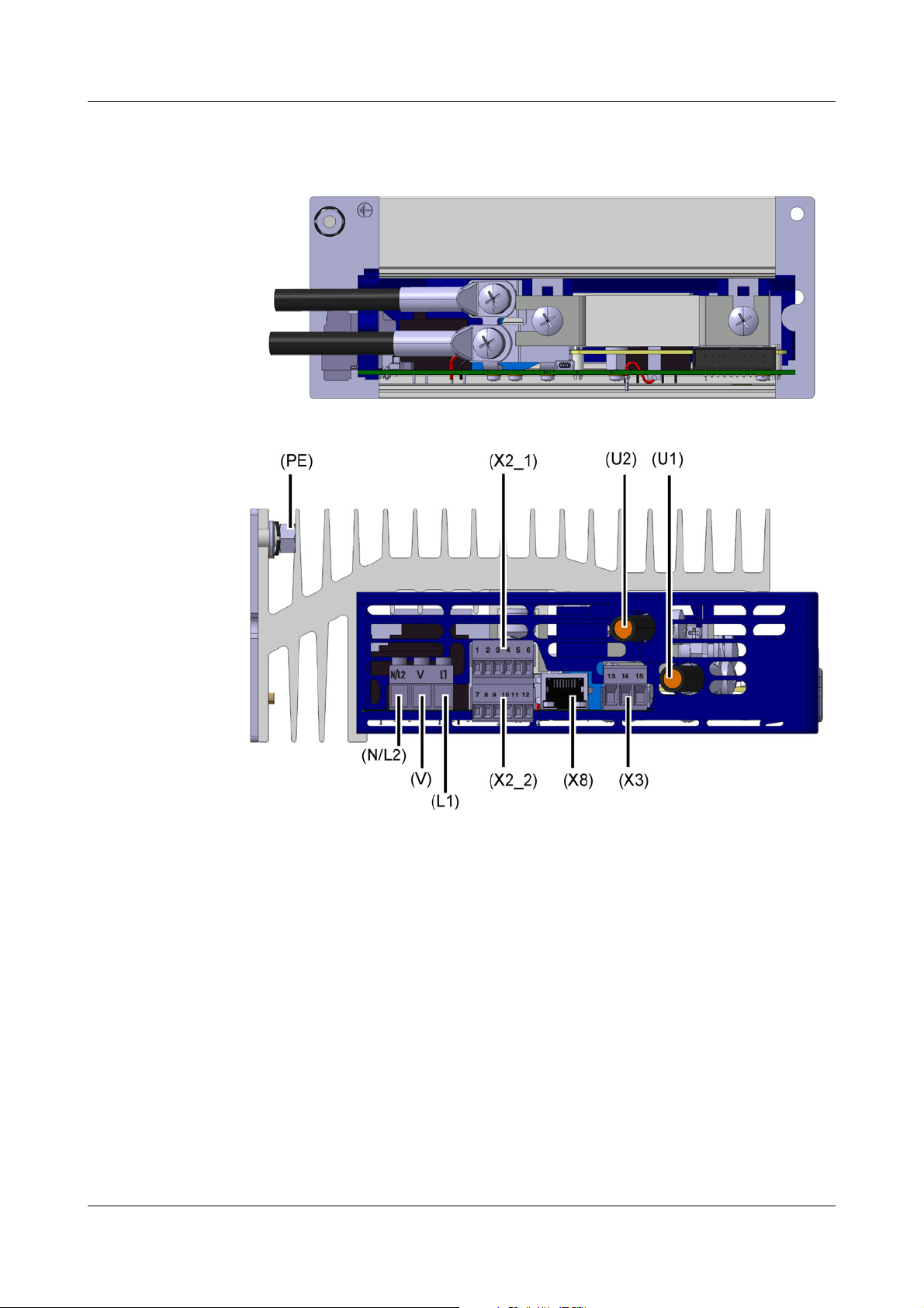
3.2.1 Type 709061/X-0X-032-XXX-XXX-XX-25X
Devices with a load current of 32 A and 50 A are equipped with plug-in screw
terminals in the control section and cable lugs in the power section.
Terminal Version Conductor cross-
section
X2_1 and X2_2 Slotted screws, blade width 2 mm
X3 Slotted screws, blade width 3 mm
U2, U1 M6 recessed head screws
For applications according to UL, only 60 °C or 60 °C / 75 °C copper conductors may be used!
N/L2, V, L1 Slotted screws,
blade width 3 mm
Ground terminal PE M6 setscrew with hexagon
nut
Width across flats 10 mm
0.2 to 1.5 mm
0.5 to 2.5 mm
6 to 25 mm
0.5 to 4 mm
(0.5 to 2.5 mm
ferrule)
(for UL application
AWG 20-12)
Cable lug
hole: 6 mm
2
2
2
2
or
2
with
Maximum
tightening
torque
0.25 Nm
0.5 Nm
5Nm
0.5 Nm
5Nm
26 2012-12-01/00561071 [SCR Power Controller TYA201]
Page 29
3.2.2 Type 709061/X-0X-050-XXX-XXX-XX-25X
3 Electrical connection
2012-12-01/00561071 [SCR Power Controller TYA201] 27
Page 30
3 Electrical connection
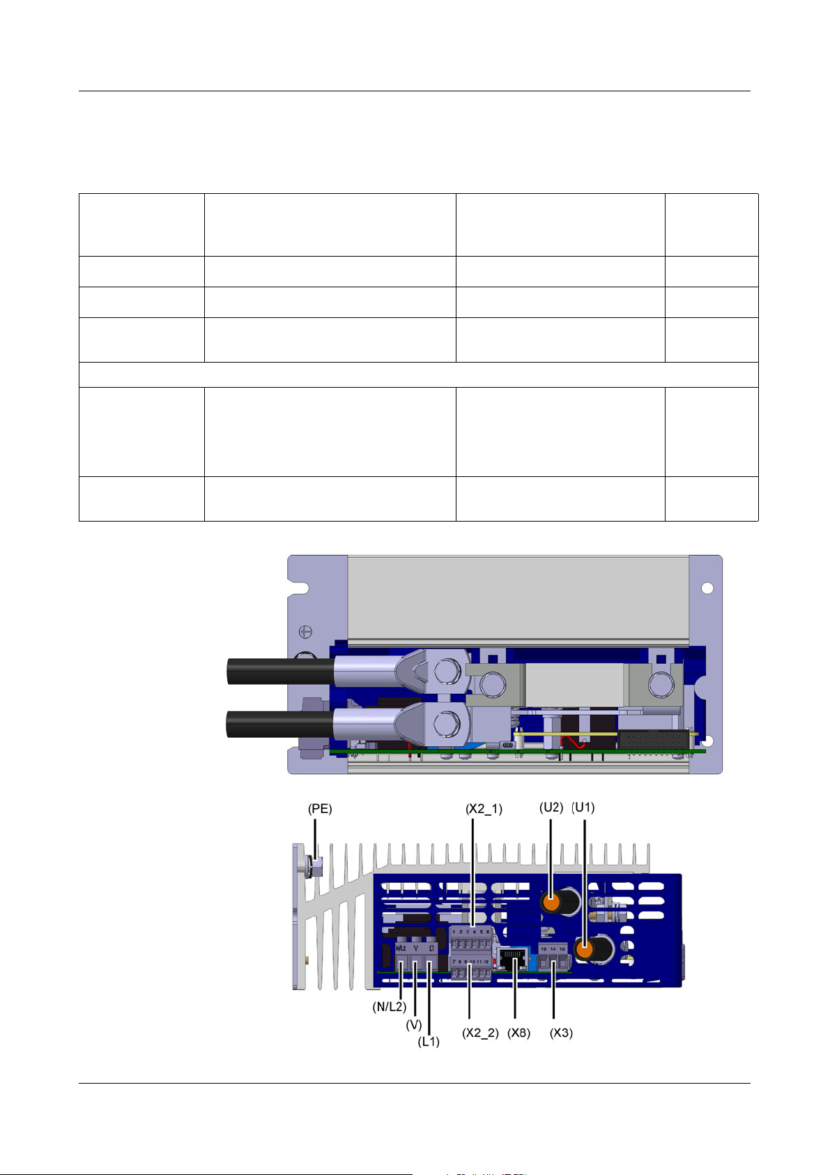
3.2.3 Type 709061/X-0X-100-XXX-XXX-XX-25X
Devices with a load current of 100 A are equipped with plug-in screw terminals
in the control section and cable lugs in the power section.
Terminal Version Conductor cross-section Maximum
tightening
torque
X2_1 and X2_2 Slotted screws, blade width 2 mm
X3 Slotted screws, blade width 3 mm
U2, U1 M6 hexagon screws, width across
0.2 to 1.5 mm
0.5 to 2.5 mm
16 to 50 mm
2
2
2
flats 10 mm
For applications according to UL, only 75 °C copper conductors may be used!
N/L2, V, L1 Slotted screws,
blade width 3 mm
0.5 to 4 mm
(0.5 to 2.5 mm
2
or
(for UL application AWG 20-
12)
Ground terminalPEM6 setscrew with hexagon nut
Width across flats 10 mm
Cable lug
hole: 6 mm
2
with ferrule)
0.25 Nm
0.5 Nm
5Nm
0.5 Nm
5Nm
28 2012-12-01/00561071 [SCR Power Controller TYA201]
Page 31

3 Electrical connection
3.2.4 Type 709061/X-0X-150-XXX-XXX-XX-25X Type 709061/X-0X-200-XXX-XXX-XX-25X
Devices with a load current of 150 A are equipped with plug-in screw terminals
in the control section and cable lugs in the power section.
Terminal Version Conductor cross-section Maximum
tightening
torque
X2_1 and X2_2 Slotted screws, blade width 2 mm
X3 Slotted screws, blade width 3 mm
U2, U1 M8 hexagon screws, width across
0.2 to 1.5 mm
0.5 to 2.5 mm
95 to 150 mm
2
2
2
flats 13 mm
For applications according to UL, only 75 °C copper conductors may be used!
N/L2, V, L1 Slotted screws,
blade width 3 mm
0.5 to 4 mm
(0.5 to 2.5 mm
2
or
(for UL application AWG 20-
12)
Ground terminalPEM8 setscrew with hexagon
nut, width across flats 13 mm
Cable lug
hole: 8 mm
2
with ferrule)
0.25 Nm
0.5 Nm
12 Nm
0.5 Nm
12 Nm
2012-12-01/00561071 [SCR Power Controller TYA201] 29
Page 32

3 Electrical connection
3.2.5 Type 709061/X-0X-250-XXX-XXX-XX-25X
Devices with a load current of 200 to 250 A are equipped with plug-in screw
terminals in the control section and cable lugs in the power section.
Terminal Version Conductor cross-section Maximum
tightening
torque
X2_1 and X2_2 Slotted screws, blade width 2 mm
X3 Slotted screws, blade width 3 mm
U2, U1 M8 hexagon screws, width across
0.2 to 1.5 mm
0.5 to 2.5 mm
95 to 150 mm
2
2
2
flats 13 mm
For applications according to UL, only 75 °C copper conductors may be used!
N/L2, V, L1 Slotted screws,
blade width 3 mm
0.5 to 4 mm
(0.5 to 2.5 mm
2
or
(for UL application AWG 20-
12)
Ground terminalPEM8 setscrew with hexagon
nut, width across flats 13 mm
Fan X14 Slotted screws, blade width 3 mm
Cable lug
hole: 8 mm
0.5 to 2.5 mm
2
Depending on the load voltage, the fan terminal X14 must be supplied with the
voltage specified below.
The lead protection must be between 2 A and a maximum of 5 A.
The fan is temperature-controlled, switches on automatically when the device
temperature reaches 85 °C, and remains in operation until the device temperature falls below 70 °C.
2
with ferrule)
0.25 Nm
0.5 Nm
12 Nm
0.5 Nm
12 Nm
0.5 Nm
Voltage supply
for
fan
Load voltage on the power controller
Tolerances Fan specifica-
tions
Load voltage AC 24 V -20 to +15 %, 45 to 63 Hz AC 24 V / 30 VA
Load voltage AC 42 V -20 to +15 %, 45 to 63 Hz
Load voltage AC 115 V -15 to +6 %, 45 to 63 Hz AC 115 V / 30 VA
Load voltage AC 230 V -15 to +6 %, 45 to 63 Hz AC 230 V / 30 VA
Load voltage AC 265 V
Load voltage AC 400 V
Load voltage AC 460 V
Load voltage AC 500 V
30 2012-12-01/00561071 [SCR Power Controller TYA201]
Page 33

3 Electrical connection
2012-12-01/00561071 [SCR Power Controller TYA201] 31
Page 34

3 Electrical connection
V V
PE PE
U2
U1
N/L2
L1
2
1
+
–
I
x
4
3
+
–
U
x
E
S
A
3
4
5
5kW
External manual
adjustment with
7
8
3,3V
10k
W
11
9
3,3V
10k
W
10
3,3V
10k
W
12
11
+
–
3.3 Connection diagram
Connection for Screw terminals Connection side Device
side
Voltage supply for control electronics
(Corresponds to the max. load voltage
of the ordered device type)
Protective earth PE
L1
N/L2
V
Load connection in the
tion
power sec-
U1
U2
Fan X14 20, 21 (only for load current 250 A)
Control section
Connection for Screw terminal X2_1
Current setpoint input 1
2
Voltage setpoint input (surge proof
up to max. DC +32 V)
Output DC 10 V fixed voltage
3 (GND)
4
5
(max. +10 V, 2 mA)
Ground potential 6 (GND)
Connection for Screw terminal X2_2
Firing-pulse inhibit
Surge proof up to max. DC 32 V
OFF logical "0" = 0 to +0.8 V
ON logical "1" = +2 to 3.3 V
Binary input1
Surge proof up to max. DC 32 V
OFF logical "0" = 0 to +0.8 V
ON logical "1" = +2 to 3.3 V
Binary input2
Surge proof up to max. DC 32 V
OFF logical "0" = 0 to +0.8 V
ON logical "1" = +2 to 3.3 V
GND 7, 11 Ground potential
Analog output
Various internal controller variables can
be output as a standard signal 0(4) to
20 mA, 0(2) to 10 V, 0(1) to 5 V.
8
7 (GND)
9
11 (GND)
10
11 (GND)
12
Connection side Device side
Connection side Device side
v Chapter 10.4 "Analog output (actu-
al value output)"
Master-slave
connection
Connection RJ 45 socket X8
For master-slave operation in
three-phase current economy circuit
32 2012-12-01/00561071 [SCR Power Controller TYA201]
1:1 patch cable
Page 35

3 Electrical connection
13
14
15
E
S
C
Ö
P
Optocoupler
Relay
16
17
19
18
6
7
8
9
2
3
4
5
1
16
17
19
18
(RS422/485 )Modbus
ProfibusDP
Fault signal
output
Connection for Screw terminal X3 Connection side Device side
Relay or optocoupler 13 N/O contact or collector
14 N/C contact
15 pole or emitter
Interfaces
Connection Modbus RS422 RS485 Connection PROFIBUS-DP
Plug-in screw
terminals on
the
bottom of the
case
19 TxD (-) RxD/TxD B(-) SUB-D sock18 TxD (+) RxD/TxD A(+) 8 B(-)
17 RxD (-) - 6 VCC
et 9-pin
(on the front)
16 RxD (+) - 5 GND
3 A(+)
Shielding
2012-12-01/00561071 [SCR Power Controller TYA201] 33
Page 36

3 Electrical connection
3.3.1 Single-phase operation: phase / N
In the case of power controllers with a load current of 250 A, the fan terminal
X14 must also be supplied with the specified voltage!
The lead protection must be between 2 A and a maximum of 5 A.
v Chapter 3.2.5 "Type 709061/X-0X-250-XXX-XXX-XX-25X"
34 2012-12-01/00561071 [SCR Power Controller TYA201]
Page 37

3.3.2 Single-phase operation: phase / phase
3 Electrical connection
In the case of power controllers with a load current of 250 A, the fan terminal
X14 must also be supplied with the specified voltage!
The lead protection must be between 2 A and a maximum of 5 A.
v Chapter 3.2.5 "Type 709061/X-0X-250-XXX-XXX-XX-25X"
2012-12-01/00561071 [SCR Power Controller TYA201] 35
Page 38

3 Electrical connection
3.3.3 Star connection with accessible star point (N)
In the case of power controllers with a load current of 250 A, the fan terminal
X14 must also be supplied with the specified voltage!
The lead protection must be between 2 A and a maximum of 5 A.
v Chapter 3.2.5 "Type 709061/X-0X-250-XXX-XXX-XX-25X"
36 2012-12-01/00561071 [SCR Power Controller TYA201]
Page 39

3 Electrical connection
3.3.4 Open delta connection (six wire connection)
In the case of power controllers with a load current of 250 A, the fan terminal
X14 must also be supplied with the specified voltage!
The lead protection must be between 2 A and a maximum of 5 A.
v Chapter 3.2.5 "Type 709061/X-0X-250-XXX-XXX-XX-25X"
2012-12-01/00561071 [SCR Power Controller TYA201] 37
Page 40

3 Electrical connection
3.3.5 Free-running economy circuit with purely resistive loads
For this electrical circuit, no master-slave connection is necessary.
In the case of power controllers with a load current of 250 A, the fan terminal
X14 must also be supplied with the specified voltage!
The lead protection must be between 2 A and a maximum of 5 A.
v Chapter 3.2.5 "Type 709061/X-0X-250-XXX-XXX-XX-25X"
38 2012-12-01/00561071 [SCR Power Controller TYA201]
Page 41

3 Electrical connection
Advantages The free-running economy circuit has the advantage that, on average, the sup-
ply voltage is subject to less impact stresses (asynchronous switching).
Both power controllers operate independently of each other and control the
required three-phase power precisely.
Even a possible partial load failure will not necessarily have an effect on the
temperature stability of the control loop.
709061/X-XX-XXX-001-XXX-XX-XXX (code 001) is required in the order code
for both power controllers.
3.3.6 Master-slave three-phase current economy circuit for resistive loads in star, delta connection, or transformer loads (resistive-inductive)
Note: The three-phase current economy circuit should be implemented with the TYA
202 type 709062 version, which is available ex works as a fully assembled and
configured unit, and behaves exactly like two single TYA 201 devices in master-slave operation.
However, it is also possible to operate two devices from the TYA 201 series in
master-slave operation. For this, one device is configured as the master and
the other as the slave. As soon as the devices are connected via the patch cable and switched on at the same time, the devices work in sync.
All further configuration steps are only performed on the master device and
the slave device can no longer be operated.
The slave device can be identified as the device on which no measured values
are displayed and "Slave unit" is shown on the display.
Prerequisite To facilitate symmetrical operation, the devices must have the same type key
and the same device software version.
The two devices are connected by means of a patch cable (max. length of
30 cm).
The wiring of two TYA 201 devices is shown in the diagram below.
Operating mode In the standard version, the master-slave economy circuit operates with a U
control. The control electronics of the master power controller assume the actual power control function, and drive the slave power controller in synchronization. This makes it possible to drive transformer loads. In combination with
2
the fixed cycle time and the U
ual load resistances can be achieved.
control, high voltage consistency of the individ-
2
2012-12-01/00561071 [SCR Power Controller TYA201] 39
Page 42

3 Electrical connection
In the case of power controllers with a load current of 250 A, the fan terminal
X14 must also be supplied with the specified voltage!
The lead protection must be between 2 A and a maximum of 5 A.
v Chapter 3.2.5 "Type 709061/X-0X-250-XXX-XXX-XX-25X"
40 2012-12-01/00561071 [SCR Power Controller TYA201]
Page 43

4 Operation
(1)
(2)
(3)
(4)
(5)
(7)
(6)
Observe the
switch-on se-
The voltage supplies to the control electronics and to the power section must
be switched on simultaneously.
quence
Under no circumstances should the voltage supply for the control electronics be switched on before the load voltage! This is particularly important for the operation of transformer loads and resistance loads with
a high temperature coefficient (TC >> 1)!
4.1 Display after switching on the device
Sequence If everything is wired correctly and the voltage supply is switched on, the Pow-
er LED is permanently lit in green.
At the same time, an hourglass appears on the display, after which the supply
voltage is displayed.
Error messages v Chapter 8 "Fault messages and alarms"
4.1.1 Display and control elements
Legend Comment Fig.
1
2
3
4
5 Keys:
The Power LED (green) is permanently lit when the voltage supply is connected.
Flashes at regular intervals if display lighting is switched off.
v Chapter 9 "What to do, if ..."
Display (96 x 64 pixels) with white background lighting. The information line at the bottom of the display shows the current
settings and error messages.
Fuse LED (red) is lit in the event of a defective semi-conductor
fuse
K1 LED (yellow) fault signal display
Increase value / previous parameter
Decrease value / next parameter
Abort / one level back
Programing / one level forward
6
7
USB setup interface
Spring clip to release the plastic case
v Chapter 8.2 "Replacing a defective semi-conductor
fuse"
2012-12-01/00561071 [SCR Power Controller TYA201] 41
Page 44

4 Operation
Designation
Measured value
Info line or error
Using and the current measured values such as currents, voltage
actual values, setpoint value load resistance, device temperature, and power
can be viewed.
This information is also displayed in the diagnosis window of the setup program.
v Chapter 7 "Setup program"
4.1.2 Displaying measured values
Overview of
measured values
Meaning of the
symbols in the
info line
At this level, the designation of the measured value is displayed in the top row,
and the numerical value together with the unit of measurement is displayed in
the middle row.
The info line shows the selected input (with terminal designation), the set subordinate control loop, and the operating mode.
It is also used to display temporary states (e.g. error messages).
v Chapter 8 "Fault messages and alarms"
Input signal Subordinate
control loop
Voltage None Phase angle control
Current U
Interface I
2
2
Operating mode
load output
Soft start in phase angle control
Burst-firing mode
Binary input1 U Burst-firing mode with
α start
Binary input2 I Half-wave control
Input signal incorrectly
configured
42 2012-12-01/00561071 [SCR Power Controller TYA201]
P General logic
Logic
(switch)
Invalid control
configured
Logic with α start
Logic with α default
values
Logic with α start and
α default values
Firing-pulse inhibit
Page 45

4 Operation
4.1.3 Meaning of the displayed measured values
Measured value Meaning Unit
Supply voltage Effective value of the measured supply voltage
(measured between the L1 and N/L2 terminals)
Load voltage
4
Effective value of the measured load voltage
(measured between the V and U2 terminals)
Load current
Power
1, 4
Load
resistance
1, 4
Output level
1, 4
4
Effective value of the measured load current
Measured effective power
Measured effective resistance
Output value of the subordinate control loop
Setpoint value Effective setpoint value for the subordinate control loop (with calculated
base load and max. output level)
Actual value
Phase
control angle
2, 4
3, 4
Measured value as a percentage of the set control variable U2, U, I2, I, or P
Currently output phase control angle
Supply frequency Currently measured supply frequency
Device
Currently measured temperature inside the power controller
temperature
V
V
A
W or
kW
?
%
%
%
°el
Hz
°C or
°F
Current input Measured value of the current input of the power controller
(measured between terminals 1 and 2 on X2_1)
Voltage
input
Measured value of the voltage input of the power controller
(measured between terminals 3 and 4 on X2_1)
1.
Is only displayed if the current transformer is fitted (option I2- / I- or P control)
2.
Is not displayed if the subordinate control loop is switched off
3.
Is only displayed for phase angle control mode
4.
Is only displayed in half-wave control operating mode
mA
V
2012-12-01/00561071 [SCR Power Controller TYA201] 43
Page 46

4 Operation
4.1.4 Display in the configuration level
Scroll bar The entry highlighted in black is selected and contains further parameters.
If there are more than 3 entries in one level, a scroll bar that shows the current
position in the menu appears.
Navigation
Numerical entry
or
selection
Once you have reached the required parameter, the or key can be
used to enter a numerical value or to select a parameter.
h Save the setting using .
If you do not want to apply the value, the entry can be aborted by selecting
.
44 2012-12-01/00561071 [SCR Power Controller TYA201]
Page 47

4.1.5 Display of error messages and special states
4 Operation
Cyclical
display
Examples
The symbols for input, subordinate control loop, and operating mode are displayed alternately with error messages or important information regarding special states in the info line.
v Chapter 8 "Fault messages and alarms"
All parameters for the maximum device extension level are listed in the following tables. Parameters that are not required are hidden depending on the
order details (see nameplate or device information) or the current configuration.
2012-12-01/00561071 [SCR Power Controller TYA201] 45
Page 48

4 Operation
4.2 Operator level
Here you will find the parameters that can be modified during ongoing operation without restarting (resetting) the device.
They can be accessed ex works without a password, but can also be protected with a 4-digit code, if necessary.
v Chapter 5.1.11 "Changing codes"
During ongoing operation, the power controller can be adapted to the plant
and optimized.
h In the measured value overview, press the key
h Select the operator level and press again.
Editing a parameter
4.2.1 Device data
The changes are effective immediately.
Once the correct setting, e.g. for display contrast, has been found, the param-
eter can be stored by pressing .
If you do not want to apply the value, the entry can be aborted by pressing
.
Value range Description
0 to 50 to 100 % 50 % is set ex works.
0000 to 1440 min 0000 minutes are set ex works,
which means the display is not switched off.
k / bold = factory setting
4.2.2 Power controller
Value range Description
0 to 70 to 90 °el 70 °el are set ex works.
If "α start" is set to "No" in the configuration, this window is
not displayed and α start is set to 0 °el.
46 2012-12-01/00561071 [SCR Power Controller TYA201]
Page 49

4 Operation
10 % to max. load
current for the device type +10 %
Current load current
0 to 999.99 Ω
Current resistance
k / bold = factory setting
4.2.3 Setpoint value configuration
Value range Description
0 to 180 °el In logic operation, the phase angle of each sinusoid can
Current limiting:
It is possible to modify the current limit value in phase
angle control mode during operation.
This window is not displayed if "Current limiting" is set to
"no" in the configuration.
Resistance limitation:
Indirect temperature limit for a heating element with positive temperature coefficients
be varied.
This means that excessive electrical impact stresses on
the load can be prevented.
Current load voltage
and current
Current load voltage
Current load voltage
0 to U
of the load voltage,
0 to P
of the power
0 to I
of the max. load current
0 to 100 %
of the output level
0 to U
of the load voltage,
0 to P
of the power
0 to I
of the max. load current
0 to 100 %
of the output level
k / bold = factory setting
nom.
nom.
nom.
nom.
nom.
nom.
to 1.15 U
to 1.15 P
nom.
nom.
In the case of continuous SCR control via the analog input, the maximum actuating variable at the measuring
range end (e.g. 20 mA) can be varied during operation.
The displayed value depends on the "Subordinate control
loop" setting:
2
U
and U: display in V (example: 0 to 230 to 264.5 V)
P: display in W (example: 0 to 4600 to 5290 W)
2
I
and I: Display in A (example: 0 to 20 A)
None: Display in % (example: 0 to 100 %)
In the case of continuous SCR control via the analog in-
put, the base load at the measuring range start (e.g. 0 mA)
can be varied during operation.
The displayed value depends on the "Subordinate control
loop" setting.
2012-12-01/00561071 [SCR Power Controller TYA201] 47
Page 50

4 Operation
4.2.4 Monitoring
Current measured
value
The value to be monitored can be adjusted.
v Chapter 5.1.5 "Monitoring"
The load voltage was used in this example.
Value range Description
0 to 9999.9 The absolute minimum limit value of load voltage, load current, pow-
er, resistance, supply voltage, or device temperature can be monitored.
v Chapter 5.1.5 "Monitoring"
Example:
If the voltage falls below 20 V, an alarm is issued.
0 to 9999.9 The absolute maximum limit value of load voltage, load current, pow-
er, resistance, supply voltage, or device temperature can be monitored.
v Chapter 5.1.5 "Monitoring"
Current measured
value
Current deviation
from teach-in.
I.e. at > 0 %
the load has become
more high-resistance; at < 0 % the
load is more low-resistance.
0 to 1 to
9999.9
0 to 10 to
100 %
Example:
If the voltage exceeds 100 V, an alarm is issued.
The switching differential at the minimum or maximum limit value
Partial load failure or partial load short circuit:
The monitoring value for the percentage modification of the load is
set (undercurrent or overcurrent).
v Chapter 5.1.5 "Monitoring"
By displaying the current deviation from the teach-in value, it is possible to check whether, for example, an output level-dependent resistance modification is present.
k / bold = factory setting
48 2012-12-01/00561071 [SCR Power Controller TYA201]
Page 51

4 Operation
This function is not configured ex works.
This window only appears if the following setting has been
made in the configuration level:
h Press the key to switch to the configuration level
h Set Monitoring
h Press the key
The "Manual teach-in" function is now configured.
h Change to the operator level
teach-in
h Press the key
A screen now appears asking whether the state should be ap-
plied now. If so:
h Press the key to apply the current load state as the OK
status.
A change in the load (load error) will be evaluated by the device
on the basis of this status.
k / bold = factory setting
rTeach-in type load monit. rManual
rMonitoring rLoad monit.
2012-12-01/00561071 [SCR Power Controller TYA201] 49
Page 52

4 Operation
50 2012-12-01/00561071 [SCR Power Controller TYA201]
Page 53

5.1 Configuration level
or PROFIBUS-DP
v Chapter 5.1.1 "Device data"
v Chapter 5.1.2 "Power control-
ler"
v Chapter 5.1.3 "Analog inputs"
etc.
The configuration level contains parameters for configuring the power controller.
If the parameters at this level are modified during operation, the power controller is locked (inhibit) as a result. In this state, it does not provide any power.
When the configuration level is exited, a restart (reset) is performed and the
power controller provides the required power once again.
This level can be locked with a password.
However, no password is set ex works.
All parameters for the maximum device extension level are listed in the following tables. Depending on the device version (see nameplate) or configuration, parameters that are not required are hidden.
The configuration level can be accessed from the overview of measured values by pressing the following keys:
h In the measured value overview, press the key
5 Configuration
Parameter
groups
h Select the configuration level and press .
The parameters are combined in the following groups, which are explained in
detail as sub-chapters in the tables on the following pages.
2012-12-01/00561071 [SCR Power Controller TYA201] 51
Page 54

5 Configuration
5.1.1 Device data
Basic settings for display and temperature unit.
Value/settings Description
Temperature unit
°C Defines the unit for the displayed temperatures, such as the
°F
device temperature.
Display contrast
Switch-off
display lighting
Apply factory settings
0 to 50 to 100 % Bright/dark contrast setting
0000 to 1440 min After the set number of minutes, the background lighting of
Apply now? If the PGM key is pressed, the factory settings are restored.
k / bold = factory setting
5.1.2 Power controller
Settings for the switching behavior of the power controller in the system.
Value/settings Description
Mains switching
variant
Single-phase operation
Free-running
economy circuit
Economy circuit
master
Economy circuit
slave
the display switches off. Power LED (green flashes).
0000 means: lighting is always switched on
v Chapter 3.3.1 "Single-phase operation: phase / N"
or
Chapter 3.3.2 "Single-phase operation: phase /
phase"
Note:
- Check for clockwise phasing
- Only possible with P-control (code 001 in order code)
v Chapter 3.3.5 "Free-running economy circuit with
purely resistive loads"
One device is set as the MASTER and the other as the SLAVE.
This makes a three-phase current economy circuit possible.
v Chapter 3.3.6 "Master-slave three-phase current
economy circuit for resistive loads in star, delta connection, or transformer loads (resistive-inductive)"
v B 709062.0
SCR control Continuous (power
controller)
Logic (switch) Note:
k / bold = factory setting
The power controller provides the power for the load continuously depending on the default setpoint value.
Subordinate control loop cannot be set!
The power controller acts like a switch and provides the power
by either switching ON or OFF.
52 2012-12-01/00561071 [SCR Power Controller TYA201]
Page 55

Operating mode
u
t
a
u
t
a
u
t
(Is displayed in the
measured value level in the info line)
Value/settings Description
Burst-firing
mode
- For slow control loops
- For free-running economy circuit
- Low EMC interference through zero-voltage switching
- No reactive power is generated
5 Configuration
Phase angle
control mode
Half-wave control
- For fast control loops,
such as lighting controls
- No flickering
Note:
Subordinate control loop cannot be set!
The half-wave control operating mode is only possible in single-phase power controller operation. It is a special type of
phase angle control mode used, for example, for vibrating
magnets. In half-wave control, one SCR branch remains permanently locked so that only the positive half-wave is allowed
to pass through.
The specified setpoint value is converted to a phase control
angle of 180 °el. to 0 °el.
In this operating mode, it is not possible to measure either
load voltage or load current, which makes a subordinate control loop impossible.
k / bold = factory setting
2012-12-01/00561071 [SCR Power Controller TYA201] 53
Page 56

5 Configuration
Phase angle α
0 to 20 mA
0 to 10 V
Analog input
Value/settings Description
Subordinate control
loop
U2, U, I2, I, P Note:
The subordinate control loop only appears for:
Power controller r SCR control rContinuous (controller).
Subordinate control loops are used to eliminate or compensate external
disturbances, such as fluctuations in the supply voltage and
changes in load resistance, which would have a negative effect on the control loop.
The U setting is used when the load voltage should be directly
proportional to the default setpoint value.
The I setting is used when the load current should be directly
proportional to the default setpoint value.
The following subordinate control loops have proven advantageous for heating elements that do not have a linear temperature behavior or are subject to aging:
2
U
is used for:
- Positive temperature coefficient, molybdenum disilicide
- If
R ∪ is constant
- Brightness controls
2
I
is used for:
- Negative temperature coefficient (TC)
P is used for:
- Temperature-dependent temperature coefficient
- Free-running economy circuit
- General applications
- SIC load with automatic aging compensation
Switched off The diagram shows how the phase angle is specified via a
standard signal without a subordinate control loop.
54 2012-12-01/00561071 [SCR Power Controller TYA201]
k / bold = factory setting
Page 57

Value/settings Description
u
t
500ms
520
u
t
500ms
520
u
t
u
t
a a
Cycle time Fixed (500 ms)
(For slow heating elements)
5 Configuration
Note:
This setting is only available in burst-firing mode.
For example, for a fixed period of 500 ms, 5 sine waves are
switched on and 20 switched off at an output level of 20 %.
Min. ON period
α start
Fastest possible
(For quick-response
heating elements)
With this setting, the cycle time is variable. At the required output level, the device attempts to find the shortest possible cycle time for entire sine wave cycles. At an output level of 20 %,
this relates to one sine wave ON and four sine waves OFF.
None
3 full sine waves Dependent on the cycle time setting.
At least 3 full sine waves are always let through.
At an output level of 50 % and fastest possible cycle time,
3 sine waves are switched on and 3 switched off.
Note:
Particularly suitable for the control of transformer loads
No Note:
Yes
This setting is available in continuous burst-firing mode and in
logic operation.
No: for resistive load
Yes: for transformer loads
If set to "Yes", the first half-wave of each pulse group is cut
with the set phase control angle α.
Angle α start 0 to 70 to 90 °el Phase control angle for α start
Soft start
2012-12-01/00561071 [SCR Power Controller TYA201] 55
No This setting determines the starting behavior of the power
controller after power ON and is deactivated ex works.
k / bold = factory setting
Page 58

5 Configuration
u
t
Softstartzeit
u
t
Cycle time
Value/settings Description
Yes "Yes" means that a soft start with phase angle control or pulse
groups is performed after power ON.
Soft start type
With phase angle
control
This parameter only appears if soft start is set to "Yes."
Soft start type "With phase angle control" is available in the
phase angle control mode and in the burst-firing mode.
Phase angle control:
Starting from 180°, the phase control angle α is steadily reduced until the correct phase angle for the default setpoint
value is reached.
Burst-firing mode:
Starting from 180°, the phase control angle α is steadily reduced until a full wave has passed through.
This ends the soft start and a switchover to burst-firing mode
is performed.
Note: If the output level is reduced to 0 % for longer than 8
seconds, a soft start is initiated again as soon as the output
level is increased again.
If, during the soft start phase, current limiting is activated, the
soft start duration is extended because the phase control angle cannot be reduced further during current limiting.
With pulse groups This setting is only available in burst-firing operating mode
with a fixed cycle time and with the fastest possible cycle
time.
During the soft start time, the ON/OFF ratio is
increased from 0 to a maximum of 100 %.
Soft start duration 1 to 65535 s Specifies the duration of the soft start.
Note: Due to the system, when current limiting is switched on,
the soft start duration is at least 4 s, even if a shorter duration
is configured as the soft start duration.
k / bold = factory setting
56 2012-12-01/00561071 [SCR Power Controller TYA201]
Page 59

Value/settings Description
Current limiting No No current limiting
Yes The current limiting is implemented via phase angle control. In
this case, the load current is monitored on the basis of the set
current limit value and only the phase control angles that do
cause the current limit value to be exceeded are permitted.
If burst-firing mode is set, the current limiting only operates
during the soft start that is realized via a time-limited phase
angle control.
It is also possible to activate an external current limit value
via a binary input.
v Chapter 5.1.6 "Binary inputs"
5 Configuration
Current limit value 10 % to max. load
current +10 % of the
device type
Resistance limitation
No No limitation through load resistance
Yes The load resistance is monitored to ensure the set resistance
Resistance limit
value
Load type resistance limitation
0 to 999.99 Ω If the load resistance is greater than this value,
Resistive load This setting is to be used for purely resistive load.
Transformer load This setting is only to be used for a resistive load via a trans-
Varies depending on the device type.
For 20 A power controllers, 2 to 22 A can be set.
v Chapter 1.3 "Order details"
Note:
Resistance limitation is only possible in the case
controllers with integrated subordinate control loop P (code
001 in the
limit value is not exceeded.
For phase angle control, the limitation is implemented through
the phase control angle α.
For burst-firing mode, the limitation is implemented through
the ON/OFF ratio of the sine waves.
order code).
of power
v Chapter 6.6 "Resistance limitation (R control)"
limitation is implemented through phase angle control or limitation of the switched sine waves.
Note:
This parameter only appears in the phase angle control operating mode.
former.
Dual energy management
Switched off This parameter only appears with the following settings:
Device1
Device2
Cycle time: fixed (500 ms),
Operating mode: burst-firing mode.
This setting allows 2 devices to be configured in such a way
that they do not simultaneously draw power from the power
supply at small output levels.
This prevents current peaks.
v Chapter 6.4 "Dual energy management"
k / bold = factory setting
2012-12-01/00561071 [SCR Power Controller TYA201] 57
Page 60

5 Configuration
5.1.3 Analog inputs
The power controller has a voltage and a current input.
These inputs (default setpoint value) specify the output to be provided by the
power controller at the load output.
In most cases, this signal is sent as a standard signal from an electronic controller or PLC and is adjusted with these settings.
Value/settings Description
Current measuring
range
0 to 20 mA This setting specifies which current standard signal is con4 to 20 mA
Customer-specific
nected.
1
v Chapter 3.3 "Connection diagram"
Current measuring
range, start
Current measuring
range, end
Voltage measuring
range
Voltage measuring
range, start
Voltage measuring
range, end
0 to 20 mA Note: This parameter only appears if "Customer specific" is
set for the current measuring range (see above)!
0 to 20 mA Note: This parameter only appears if "Customer specific" is
set for the current measuring range (see above)!
0 to 10 V This setting specifies which voltage standard signal is con2 to 10 V
0 to 5 V
1 to 5 V
Customer-specific
0 to 10 V Note: This parameter only appears if "Customer specific" is
0 to 10 V Note: This parameter only appears if "Customer specific" is
k / bold = factory setting
1.
Analog input inverting:
If, for example, the current measuring range start is set to 20 mA and the current measuring range en
to 0 mA, the power controller is switched off at 20 mA and switched on at 0 mA.
nected.
v Chapter 3.3 "Connection diagram"
1
set for the voltage measuring range (see above)!
set for the voltage measuring range (see above)!
58 2012-12-01/00561071 [SCR Power Controller TYA201]
Page 61

5.1.4 Setpoint value configuration
u
t
a
-Vorgabe
Phase angle α
0 to 20 mA
0 to 10 V
Analog input
This setting determines which input specifies the setpoint value, how high the base
load is, and which alternative value should be applied in the event of an error.
Value/settings Description
Setpoint input
Current input This setting specifies which analog input supplies the setpoint
value for the power output.
Note:
Voltage input
These inputs can also be used for logic operation.
v For switching level, see Chapter 10.7 "General char-
Binary input1 Note:
This setting is only available if power controller
rLogic (switch) is set.
Binary input2
Via interface Means that the setpoint value for the power output is provided
In this case, the power controller is controlled in the same way
as a solid-state relay (SSR) via binary input 1 or 2:
Contact: closed
(for control direction set ex works).
via an interface.
5 Configuration
acteristic data"
rSCR control
r100 % and open r0%
α input
This setting is only available power controller rSCR control rLogic (switch) is set.
This setting specifies which signal
should be fixed
.
the α default values should control or whether it
The "α default values" value is a phase angle with which all sine waves are cut to limit
the power.
Not to be confused with the value for α start!
No input No phase angle is specified (full sine waves)
Voltage input or cur-
rent input
This standard signal specifies the phase angle as shown in
the diagram.
Value, adjustable The phase angle is entered as "α default value".
Via interface The phase angle is set via an interface.
α input value
0 to 180 °el This is the phase angle if "Value, adjustable" was set under α
input value.
2012-12-01/00561071 [SCR Power Controller TYA201] 59
Page 62

5 Configuration
Control signal
P
Base load: 680 W
Maximum
Output level: 3680 W
0 mA
20 mA
3000W 0...20mA
Ⳏ
Base load
Input in the event of
an error
Value in the event
of an error
Maximum
actuating variable
Current, voltage, and interface input are monitored for errors
(wire breaks or bus errors). This setting specifies which alternative value the power controller should use if the default setpoint value is incorrect.
The last valid value is used ex works.
Last value
Voltage input or cur-
rent input
If, for example, an error (e.g. wire break) now occurs at the
current input, which is set ex works for the default setpoint
value, the power controller uses the value at the voltage input.
Value, adjustable This means that the "Value in the event of an error" is used.
000.0 This value is used in the event of an error.
0 to U
om.
of the load voltage,
0 to P
P
nom.
of the power
nom.
nom.
to 1.15 U
to 1.15
In the case of continuous SCR control via the analog input,
n-
the maximum actuating variable at the measuring range end
(e.g. 20 mA) can be varied during operation.
Note:
This setting is only available if power controller
rSCR control
rContinuous (power controller) is set.
0 to I
nom.
of the max. load current
0 to 100 %
of the output level
The unit depends on the setting for subordinate control loop
and device type:
2
- U
and U: display in V (example: 0 to 230 to 264.5 V)
- P: display in W (example: 0 to 4600 to 5290 W)
2
- I
and I: display in A (example: 0 to 20 A)
- None: display in % (example: 0 to 100 %)
Base load
0 to U
nom.
of the load voltage,
0 to P
of the power
nom.
Note:
This setting is only available if power controller
rContinuous (power controller) is set.
The unit depends on the setting for subordinate control loop
and device type:
0 to I
nom.
of the max. load current
0 to 100 %
of the output level
- For voltage: 0 to 100 % of the max. load voltage (e.g. 0V)
- For current: 0 to 100 % of the max. load current (e.g.
0A)
- For power: 0 to 100 % of the power (e.g. 0W)
- None: 0 to 100 % of the output level (e.g. 0%)
v Chapter 1.3 "Order details"
k / bold = factory setting
rSCR control
60 2012-12-01/00561071 [SCR Power Controller TYA201]
Page 63

5.1.5 Monitoring
This allows an internal measured value to be monitored for compliance with
limit values.
Depending on the switching behavior, an overrange or underrange is output at
the binary output (option: relay or optocoupler).
Value/settings Description
Limit value monitoring
Switched off No monitoring
Load voltage
Load current
Power (in W)
Power (in kW)
Resistance
Supply voltage
Device temperature
5 Configuration
These measured values can be monitored and are dependent
on the ordered device type.
Min. limit value
alarm
Max. limit value
alarm
Note: (as of software version 256.01.08)
If power controller -> SCR control -> Logic (switch) and Monitoring -> Limit value monitoring -> Load voltage, load current,
power (in W) or power (in kW) is set,
the limit value monitoring only operates in the periods in which
the SCRs have been fired.
If the SCRs block, as a general rule, the min. and max. alarms
are switched off.
0 to 9999.9 The absolute minimum limit value for load voltage, load cur-
rent, power, resistance, supply voltage, or device temperature
can be monitored.
If the measured value falls below this value, an error message
appears at the bottom of the display and the yellow K1 LED
lights up. Depending on the set control direction, the binary
output switches as shown in the diagram.
The unit of the limit value corresponds to the monitored measured value.
0 to 9999.9 The absolute maximum limit value of load voltage, load cur-
rent, power, resistance, supply voltage, or device temperature
can be monitored.
If the measured value exceeds this value, an error message
appears at the bottom of the display and the yellow K1 LED
lights up.
Depending on the set control direction, the binary output
switches as shown in the diagram.
The unit of the limit value corresponds to the monitored measured value.
2012-12-01/00561071 [SCR Power Controller TYA201] 61
Page 64

5 Configuration
Limit value hysteresis
Load monitoring
Limit value load
monitoring
Load type load
monitoring
Teach-in type load
monitoring
0 to 1 to 9999.9 Switching differential at the upper and lower limit of the moni-
toring range
None The load is not monitored.
Undercurrent
Overcurrent
Note:
This parameter is only available if the device type is equipped
with an I, I
surement can therefore be performed.
2
, or P subordinate control loop and current mea-
v Chapter 6.1 "Detection of load faults"
Note:
This setting is only available if load monitoring has been set
to under- or overcurrent.
0 to 10 to 100 % Partial load failure or partial load short circuit:
This setting specifies the percentage by which the load resistance must have decreased or increased for a load error to be
triggered.
Standard Default setting (suitable for most load types)
Infrared radiator
(short-wave)
Automatic, once The teach-in value is automatically determined once after
Especially suitable for short-wave infrared radiators
each power ON.
v Chapter 6.1.1 "Teach-in"
Manual Teach-in can be performed in manual mode or at the opera-
tor level.
v Chapter 6.2.2 "Configuring the teach-in (prerequisite
for teach-in in manual mode)"
Mains voltage drop
monitoring
v Chapter 4.2.4 "Monitoring"
Automatic, cyclical Teach-in is performed cyclically at a time interval of 1 minute.
No No monitoring
Yes
k / bold = factory setting
If the effective values of the analyzed half-waves are more
than 10 % apart, an alarm message is displayed and the binary output for the collective alarm switches depending on the
set control direction.
Immediate firing-pulse inhibit prevents the connected transformer loads from destroying the semi-conductor fuse due to
a DC component.
If there are no further supply voltage drops, the firing-pulse inhibit is removed and the power controller continues operation,
e.g. with a soft start.
62 2012-12-01/00561071 [SCR Power Controller TYA201]
Page 65

5.1.6 Binary inputs
There are 2 binary inputs and one additional binary input for firing-pulse inhibit
available, to which a potential-free contact can be connected.
The following functions can be triggered with binary input 1 and 2:
h
Switch to the configuration level rBinary inputs using the key
Value/settings Description
Changeover, phase
angle control
Switched off No changeover
Binary input1
Binary input2
Ext. binary input1
Ext. binary input2
5 Configuration
Note:
The changeover to phase angle control mode is only possible
if the setting
firing mode has been made in the configuration level.
Changeover is controlled by binary input1
Changeover is controlled by binary input2
Changeover is controlled via an interface
Changeover is controlled via an interface
rPower controller rOperating mode rBurst-
Ext. current limiting
Ext. current limit
value
Note:
This function can only be set if the following
presettings have been made:
Option 1:
Power controller
and
Power controller
Option 2:
Power controller
Power controller
Power controller
If, for example, "Binary input 1" is set here, when the binary input is closed, instead of the current limit value set under
"Power controller
"External current limit value" (further down in the table) be-
comes effective.
Switched off No ext. current limiting
Binary input1
Binary input2
Ext. binary input1
Ext. binary input2
10 % to max. load
current of the
device +10 %
Ext. current limiting is controlled by binary input1
Ext. current limiting is controlled by binary input2
Ext. current limiting is controlled via an interface
Ext. current limiting is controlled via an interface
Note:
This parameter is only available if a binary input is set for ext.
current limiting.
The max. load current varies depending on the device type.
For 20 A power controllers, 2 to 22 A can be set.
rOperating mode rPhase angle control
rCurrent limiting rYes
rOperating mode rPulse groups
rSoft start rYes
rCurrent limiting rYe s
rCurrent limit value" coming into effect, the
v Chapter 1.3 "Order details"
Key lock Switched off No key lock
Binary input1
Binary input2
Ext. binary input1
Ext. binary input2
k / bold = factory setting
Key lock is controlled by binary input1
Key lock is controlled by binary input2
Key lock is controlled via an interface
Key lock is controlled via an interface
2012-12-01/00561071 [SCR Power Controller TYA201] 63
Page 66

5 Configuration
7
8
3,3V
10k
W
Value/settings Description
External switch-off,
display lighting
Switched off
Binary input1
Binary input2
Ext. binary input1
Ext. binary input2
No external switch-off, i.e. the background lighting
behaves according to the configuration in Chapter 5.1.1
Switch-off is controlled by binary input1
Switch-off is controlled by binary input2
Switch-off is controlled via an interface
Switch-off is controlled via an interface
Control direction
inhibit input
Control direction,
binary input1
Control direction,
binary input2
The firing-pulse inhibit can be triggered when the switching
contact is closed or open.
v Chapter 3.3 "Connection diagram"
Open, load ON Ex works:
Open, load OFF
Open, inactive The function for binary input1 can be triggered when the
Open, active
Open, inactive The function for binary input2 can be triggered when the
Open, active
k / bold = factory setting
Inhibit input open, power controller supplies power.
Inhibit input closed, power controller does not supply power.
switching contact is open or closed.
switching contact is open or closed.
64 2012-12-01/00561071 [SCR Power Controller TYA201]
Page 67

5.1.7 Binary output
13
14
15
E
S
C
Ö
P
Optocoupler
Relay
13
14
15
E
S
Optocoupler
Relay
C
Ö
P
13
14
15
E
S
Optocoupler
Relay
C
Ö
P
13
14
15
E
S
C
Ö
P
Optocoupler
Relay
This parameter specifies which control direction the binary output should have. It is
controlled by the multi-input interference signal.
v Chapter 8.1 "Binary signal for collective fault"
Switch to the configuration level rBinary output using the key
h
Value/settings Description
Control direction,
binary output
N/O contact No fault message present:
5 Configuration
14 and 15 pole and N/C contact closed or
13 and 15 optocoupler collector-emitter loop high-impedance
Fault message present:
13 and 15 pole and N/O contact closed or
13 and 15 optocoupler collector-emitter loop low-impedance
N/C contact No fault message present:
13 and 15 pole and N/O contact closed or
13 and 15 optocoupler collector-emitter loop low-impedance
Fault message present:
14 and 15 pole and N/C contact closed or
13 and 15 optocoupler collector-emitter loop high-impedance
k / bold = factory setting
2012-12-01/00561071 [SCR Power Controller TYA201] 65
Page 68

5 Configuration
5.1.8 Actual value output
The actual value output is an analog output at which different internal values
can be output as a standard signal.
Value/settings Description
Signal type, actual
value output
Switched off The actual value output does not issue a signal.
0 to 20 mA
4 to 20 mA
0 to 10 V
2 to 10 V
0 to 5 V
1 to 5 V
This setting specifies the standard signal that should be out-
put at the actual value output.
The actual value output outputs the "Value to be output" in the
form of a current signal.
The actual value output outputs the "Value to be output" in the
form of a voltage signal.
Value to be output
Signal range start
value
Signal range end
value
5.1.9 RS422/485
This setting specifies the value that should be output at the
actual value output.
Load voltage Example:
Load voltage
Load current
Load current
Power (in W)
Power (in kW)
Resistance
Supply voltage
Device temperature
Setpoint value
0 to 9999.9 Lower limit for the "Value to be output"
0 to 9999.9 Upper limit for the "Value to be output"
k / bold = factory setting
2
2
The load voltage can vary between 0 and 500 V depending on
the device type.
As the signal range is set ex works to 0 to 9999.9, the end val-
ue must be adjusted to 500.0 to make use of the full signal
range.
For master-slave switching operation, the following must be
observed:
These measured values are determined in the master branch.
Exception as of software version 256.01.08:
When the power is selected (in W or kW), the three-phase cur-
rent is output on the actual value output.
Note:
Load voltage
2
= load voltage squared
Interface parameters for RS422/485 (see interface description B709061.2)
Value/settings Description
Baud rate
Data format 8-1-none Data bits-stop bits-parity check
Device address
Min. response time 0 to 500 ms
9600
19200
38400
8-1-odd
8-1-even
8-2-none
1 to 255
k / bold = factory setting
66 2012-12-01/00561071 [SCR Power Controller TYA201]
Page 69

5.1.10 PROFIBUS-DP
Interface parameters for PROFIBUS-DB (see separate manual)
Value/settings Description
Device address
1 to 125 If "0" is set as the device address, the bus fault error message
5 Configuration
is not displayed.
Data format
Motorola, Intel
k / bold = factory setting
5.1.11 Changing codes
Here, it is possible to assign passwords (4-digit numeric codes) for manual
mode, operator level, and configuration level to protect them from unau-
thorized access.
Value/settings Description
Code, manual
mode
Code, operator level
Code, config. level
0000 to 9999
0000 to 9999 0000 means: no inhibit
0000 to 9999 0000 means: no inhibit
k / bold = factory setting
0000 means: no inhibit
9999 means: level is hidden
9999 means: level is hidden
2012-12-01/00561071 [SCR Power Controller TYA201] 67
Page 70

5 Configuration
5.2 Configuration example
Requirements Load voltage 400 V
3 heating elements each with 1 kW connected in parallel
Load current: 3000 W/400 V = 7.5 A
Temperature coefficient TC = 1
Operating mode: phase angle control
Subordinate control loop: U
Base load: 0 %; maximum output level 100 %
Default setpoint value via standard signal of 0 to 20 mA.
These requirements are sufficient for the following power controllers:
Device type 709061/8-01-020-100-400-252
2
68 2012-12-01/00561071 [SCR Power Controller TYA201]
Page 71

6 Special device functions
6.1 Detection of load faults
The load monitoring function can detect and signal a load failure, partial load
failure, or a partial load short circuit.
Undercurrent This function is used for one or more heating elements connected in parallel
that are to be monitored for breakage.
Overcurrent This function is used for several heating elements connected in series that are
to be monitored for short circuits.
Function This function does not only take the decreasing or increasing load current into
consideration but also includes the load voltage in the monitoring process.
The correct load ratios of the system are saved during teach-in.
Based on this status, the load changes are continuously monitored irrespective of the required output level. In the event of a breakage or short circuit of a
heating element, the load current increases or decreases. This is detected by
the load monitor and a load fault is signaled.
Limit value A limit value must be entered in the configuration or operator level in % for the
load monitor. This limit value depends upon the number of heating elements
connected in parallel or in series.
Undercurrent
Number of
heating elements
510% -
For heating elements with a high positive or negative temperature coefficient,
a suitable limit value must be determined independently. The % value shown
below (see arrow) can be used as an aid for this.
This value represents the current deviation from the teach-in value. If the value
is > 0 %, the load has become more more high-resistance; if the value is <
0 %, it has become more low-resistance. This window can be accessed via
Operator level
rMonitoring rLimit value load monit.
For heating elements with a temperature coefficient TC ∪ 1 the limit value can
be taken directly from the following tables:
Single-phase
operation
Star connection
with separate
star points without
neutral conductor
Star connection with
common star points
without neutral conductor
Delta connection
-
413% 10 % 3 17 % 13 % 10 %
2 25 % 20 % 12 %
2012-12-01/00561071 [SCR Power Controller TYA201] 69
Page 72

6 Special device functions
N
L1
L3L2L1
L3L2L1
L3L2L1
N
L1
L3L2L1
L
3
L2L1
Number of
heating elements
150%
Example:
2 heating
elements
Overcurrent
Single-phase
operation
Star connection
with separate
star points without
neutral conductor
Star connection with
common star points
without neutral conductor
50 % 21%
The specifications in % refer to load current changes
Number of
heating elements
Single-phase operation
Star connection without
neutral conductor
610% -
Delta connection
Delta connection
-
513%10 %
-
417%10 % 10 %
3 25 % 14 % 13 %
2 50 % 25 % 26 %
Example for 2
heating elements
The specifications in % refer to load current changes
As a general rule, load monitoring does not yet take place during the soft start
phase (which can last for longer due to active current limiting) as the standard
operating range of the load has not yet been reached. Teach-in cannot yet be
performed in this phase either.
70 2012-12-01/00561071 [SCR Power Controller TYA201]
Page 73

6.1.1 Teach-in
6 Special device functions
Depending on the configuration of the parameter "Load monit. teach-in",
teach-in, i.e. determination of the load measured values in the OK status, is either performed once automatically after power ON or automatically and cyclically, repeatedly every minute or manually.
"Manual"
teach-in
For "Manual teach-in", the power controller must be told once after the operating point has been reached that it is now to perform the teach-in.
This is possible in the operator level or in manual mode.
v Chapter 4.2.4 "Monitoring"
v Chapter 6.2.2 "Configuring the teach-in (prerequisite for teach-in in manu-
al mode)"
The teach-in values are then permanently saved. It is not necessary to perform
the teach-in again when the power controller is switched off and on again.
The teach-in can be repeated whenever necessary. The old teach-in values are
then overwritten by the new ones.
The teach-in values are only deleted if the load monitoring teach-in parameter
is explicitly configured to "Manual teach-in" or when the factory setting is applied. The teach-in is not affected by reconfiguration of other parameters.
From software version 256.01.08, the determined teach-in values are also
transferred when the set-up data of one power controller is transferred to another.
If "Manual teach-in" has been configured but no teach-in has been conducted,
the message "Teach-in load monitoring!" appears on the display as a reminder.
Manual teach-in can only be performed on the device itself, not via the setup
program.
To ensure that the load ratios for later operation are recorded precisely, only
perform the teach-in at a load current of at least 20 % of the rated value.
Teach-in
"Automatically
(once)"
"Automatically (once)" means that the teach-in values are temporarily saved
after each power ON. This setting is only suitable for heating elements with a
temperature coefficient of TC ∪ 1.
They are deleted again when the power controller is disconnected from the
supply voltage. When the power is switched on again, the load monitoring
function is inactive until the new teach-in has been performed.
To ensure that the load ratios for later operation are recorded precisely, the
teach-in in phase angle control is not performed until the output level has
reached at least 30 %. (This constraint is not necessary for burst-firing mode
as the current of a fired SCR power controller is always high enough. In this
case, the teach-in is always performed shortly after power ON or – if configured – after completion of the soft start.)
2012-12-01/00561071 [SCR Power Controller TYA201] 71
Page 74

6 Special device functions
Load voltage
Load current
Setpoint value
Teach-in
"Automatic (cyclically)"
"Automatically (cyclically)" means that the teach-in values are temporarily
saved again at intervals of 1 minute. This setting is particularly suitable for SIC
heating elements as in this case the resistance in the load point changes with
time due to aging.
When the power controller is disconnected from the supply voltage, the teachin values detected last are deleted and recalculated once voltage supply has
returned.
6.2 Manual mode
In this case, the setpoint value can be manually preset in % without the need
for external wiring via the analog input.
6.2.1 Default setpoint value in manual mode
Starting Manual mode, as set ex works, can be accessed without entering a code.
h Press the key once (selection menu)
h Press the key again (manual mode)
h Use the or key to increase or decrease the setpoint value
The changes become effective immediately at the load output and are indicated on the display.
The setpoint value for manual mode is not saved in the event of a power failure!
6.2.2 Configuring the teach-in (prerequisite for teach-in in manual mode)
The teach-in function records the current/voltage ratio of a load in the OK status.
This function is not configured ex works.
v Configuration level See "Teach-in type load monitoring" on page 62.
Configuring
"manual"
teach-in
The power controller is in the "Measured value overview" level.
h Press the key
h Config. level
rent
rTeach-in type load monit. rS "manual"
rMonitoring rLoad monitoring rUndercurrent or overcur-
h Press the key
II
h Press the key twice
The device performs a reset.
72 2012-12-01/00561071 [SCR Power Controller TYA201]
Page 75

If the teach-in is being performed for the first time, the message "Teach-in load
monitoring" appears in the bottom line of the display.
6.2.3 Performing teach-in in manual mode
The power controller is in the "Measured value overview" level.
h Press the key twice to return to manual mode.
If the teach-in is being performed for the first time, the message "Teach-in load
monitoring" now appears in the bottom line of the display.
6 Special device functions
Repeating
teach-in
h Press the key and the following message will appear:
h Press the key to apply the current load state as the OK status.
A change in the load (load error) will be evaluated by the device on the basis of
this status.
The teach-in can be repeated any number of times in manual mode.
h Press the key and the following message will appear:
h Press the key to apply the current load state as the OK status.
2012-12-01/00561071 [SCR Power Controller TYA201] 73
Page 76
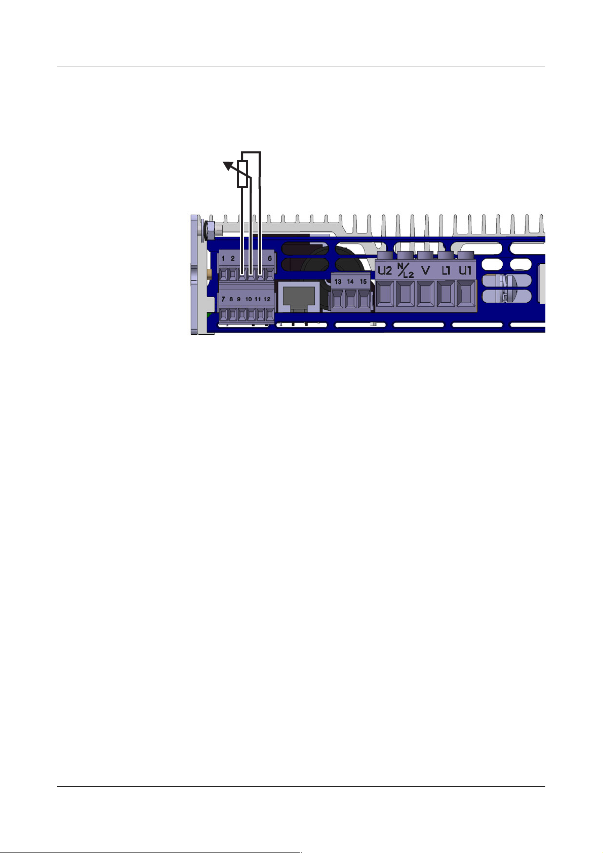
6 Special device functions
A
S
E
6.3 Default setpoint value via potentiometer
For this, a 5 kΩ potentiometer is connected to the voltage input.
It is supplied with DC 10 V at terminal 5 of the power controller.
h Configuration level
10 V
h Configuration level
voltage input
Now the power controller power is preset via the external potentiometer.
6.4 Dual energy management
This allows setpoint values of up to 50 % each to be preset on 2 power controllers without causing current peaks in the network when they are switched
on simultaneously.
No current peaks are caused in the network even if the setpoint values are
asymmetrically distributed, e.g. 30 % and 70 %.
More than
2 power controllers
Prerequisites
If more than 2 power controllers are required in a system, they must be divided
into 2 groups.
The "Dual energy management" parameter (Device1 and Device2) has to be
set in each group.
- Both devices must be connected to the same phase
- The control electronics and the load circuit must have the same phase
- Synchronize both devices by switching them on simultaneously
- Burst-firing mode must be configured
- The cycle time must be set to 500 ms (fixed)
- In each group, one TYA201 power controller must be configured as
Device1 and the other TYA201 power controller as Device2.
rAnalog inputs rSet voltage measuring range 0 to
rSetpoint value config. rDefault setpoint value rSet
74 2012-12-01/00561071 [SCR Power Controller TYA201]
Page 77

6 Special device functions
t
t
Device 1
Output level 20%
Device 2
Output level 60%
I
Thy2
t
I
mains
Sum of all
currentsMains
The power controllers switch on chronologically staggered. Starting from the
dashed lines, the dispersion of power takes place symmetrically to the left and
right (see arrows). For as long as the total output level of the two devices is below 100 %, overlaps of the two device currents in a single phase are prevented. The next power level in the network is not started until the total output
level exceeds 100 %.
If a power controller performs a restart when the configuration level
is exited, it no longer operates synchronously with the others.
All power controllers have to be switched on again simultaneously
via a joint main switch!
2012-12-01/00561071 [SCR Power Controller TYA201] 75
Page 78

6 Special device functions
Controller
Furnace
Sensor
SCR
power unit
Supply
voltage
y
R
x
y
-
w
P
230V
ΔP–
U0–1U,()
2
R
--------------------------
09U,()
2
R
------------------
0,81 P
230 V
•===
6.5 Subordinate control
Subordinate control loops are used to eliminate or compensate for external interference, such as fluctuations in the supply voltage and changes in resistance which would have a negative effect on the control loop.
6.5.1 Closed control loop without subordinate control
Example
Furnace/kiln
control system
The supply voltage is connected to the power controller. The controller derives
the output level y
from the difference between the set value (w) for the fur-
R
nace temperature and the actual value (x) which is acquired by a sensor inside
the furnace. The output level can vary over the range 0 to 100 % and is output
as a standard signal, for example 0 to 10 V. The output level is fed to the power controller.
The task of the power controller is to feed energy to the heating elements in
the furnace, proportional to the controller output level:
- For an SCR power controller using phase angle control, this means that
it alters the firing angle over the range from 180 ° to 0 °, corresponding to a
controller output level of 0 to 100 %.
-If the SCR power controller is using the burst-firing mode, it increases
the duty cycle T from 0 to 100 %, corresponding to a controller output level
of 0 to 100 %.
If the supply voltage drops from AC 230 V to AC 207 V (-10 %) at a controller
output level YR, the power fed to the furnace is reduced by 19 %.
(2)
P
: Power in the load resistance at a supply voltage U of 230 V
230V
ΔP: Power reduction resulting from reduced supply voltage
R: Resistance of the load
This 19 % reduction in the energy being fed in means that the
furnace temperature falls.
Disadvantage: A continuing constant temperature is no longer assured.
76 2012-12-01/00561071 [SCR Power Controller TYA201]
The power controller recognizes the deviation through the relatively slow re-
Page 79

6 Special device functions
Controller
Sensor
Controlled
system
SCR
power controller
Voltage supply
subordinate
control loop
y
R
x
y
w
-
P
Load
U
Load
2
R
--------------
=
(3)
P
Load
U
Load
2
∼
(4)
U
Load
2
input signal of power controller∼
(5)
sponse of the temperature control loop and increases its output level (yR) until
the furnace reaches the original temperature (250 °C) again.
6.5.2 Closed control loop with subordinate control
To avoid power variations caused by supply voltage fluctuations, a subordinate control loop is built into the power controllers. The subordinate control
loop immediately counterbalances any fluctuations in the amount of supplied
power. This means that the power controller always provides a power level at
the output (y) that is proportional to its input signal (y
subordinate control loop is shown in Figure .
). The principle of an
R
A distinction is made between U
most applications. There are however some applications where an I
trol has advantageous control-loop characteristics (requires recording of the
current in the power controller).
The three different types of subordinate control are described in the following
chapters.
2
U
control Considering the power P
by the voltage on the load, U
Equation 3 shows that, for a constant load resistance, the power in this resistance is proportional to U
A power controller with a U
square of the load voltage is proportional to the signal input (e.g. 0 to 20 mA)
to the controller.
2
, I2, and P control loops. U2 control is used in
in a resistive load, we know that it is determined
Load
and the resistance of load, R, as follows:
Load
2
.
Load
2
control will regulate in such a manner that the
2
or P con-
Combining equations 5 and 4, we can see that the power in the load resistance is proportional to the input signal to the power controller.
2012-12-01/00561071 [SCR Power Controller TYA201] 77
Page 80

6 Special device functions
P
Load
input signal of power controller (0 to 20 mA)∼
U
Load
2
R
---------------
Heating elements that have a positive temperature coefficient (TC), i.e. where
the electrical resistance increases with increasing temperature, are usual-
ly driven by a power controller that incorporates a subordinate control (U
control) (Figure 1).
These are resistive materials such as
- Kanthal-Super
-Tungsten
-Molybdenum
- Platinum
- Quartz radiators
Their cold resistance is substantially lower than their resistance when hot (by a
factor of 6 to 16). These heating elements are usually run at temperatures
above 1000 °C.
(6)
2
Figure 1: Heating element with a positive TC
Power controllers need current limiting for the starting phase. The constant
current and the increasing resistance mean that, initially, the power in the heating element increases in proportion to R, since the power P = I
2
· R.
When the current falls below the preset limit value, the automatic current limiting is no longer effective, and the power controller operates with the subordi-
2
nate U
control, i.e. if the resistance continues to increase at a constant voltage level, the power fed to the heating elements is automatically reduced
P
= .
Load
78 2012-12-01/00561071 [SCR Power Controller TYA201]
Page 81

6 Special device functions
This effect supports the complete control loop. As the furnace temperature rises towards the set value, the power fed to the furnace is reduced (at the same
load voltage level). This means that, through the power controller alone, the
approach to the setpoint value is slowed. This damps out any tendency to
overshoot the final temperature.
Other applications for U
2
control are:
- In lighting systems: in this case, the intensity of the lighting is proportional
- Some resistance materials have a TC that is close to 1. These include heat-
2
.
to U
ing elements made from nickel/chrome, constantan, etc. This does not
place any special demands on the SCR power controller (e.g. current limiting). The resistance characteristic for a heating element with a TC ∪ 1 is
shown in Figure 2.
Figure 2: Heating element with TC ∪ 1
2
control Current control (I2 control) is advantageous for heating elements with a nega-
I
tive TC, where the electrical resistance becomes smaller as the temperature
increases (Figure 3).
This behavior is shown by non-metallic materials such as graphite or glass
melts. Molten glass is not usually heated by heating elements but by letting a
current flow through the melt, so that the electrical energy is converted directly
into heat in the molten material. The current is applied through electrodes.
2012-12-01/00561071 [SCR Power Controller TYA201] 79
Page 82

6 Special device functions
R
100 %
u
Up to 4 R
Aging
1050 °C
New
Figure 3: Heating element with a negative TC
Looking at the power equation P = I
same regulatory effect on the power as already described for the U
2
· R, we can see that an I2 control has the
2
control.
This means that, by regulating a constant current while the temperature rises,
the power in the process is automatically reduced as the resistance falls.
P control Power control (P control) is a continuous regulation of the product U · I, the
power. In this case, there is a precise linear relationship between the output
power and the level of the signal input (e.g. 0 to 20 mA) to the SCR power controller.
A typical application of this type of subordinate control is for regulating heating
elements which are subject to long-term aging combined with a temperaturedependent change in resistance, as is the case with silicon carbide elements
(Figure 4).
Figure 4: Resistance changes for silicon carbide
80 2012-12-01/00561071 [SCR Power Controller TYA201]
Page 83

6 Special device functions
R
Old
4
----------
P
New
U
NewINew
•
U
Old
2
----------
2I
Old
• U
OldIOld
• P
Old
====
(12)
Silicon carbide heating elements have a nominal resistance that can alter by a
factor of 4 over the long term. So when dimensioning a system, it is necessary
to provide power controllers that can produce twice the (nominal) power for
the heating elements.
This results in double the current for the SCR power controller.
Which
operating mode
is suitable for
which load?
Old = old state of the heating element R
New
=
New = new condition of the heating element
The relationship is illustrated by the following formula:
P control is also used for free-running economy circuits running off a threephase supply network.
Operating mode Resistive load Inductive
load
TC constant TC positive TC nega-
tive
Longterm aging
Phase angle control XX
Phase angle control
XXX
with
current limiting
Burst-firing mode X
Burst-firing mode with
XX
α start
Burst-firing mode and
XXX
current limiting
Subordinate control
2
U
2
I
XX X
XX
P XX
2012-12-01/00561071 [SCR Power Controller TYA201] 81
Page 84

6 Special device functions
6.6 Resistance limitation (R control)
.
This is only possible in power controllers with current and voltage
measurement that are fitted with subordinate control P (Code 001
in the order code) and only functions for load resistors with positive
temperature coefficient.
In three-phase economy circuits, no direct resistance limitation is
possible because the individual resistance value is not recorded.
However, the limiting function itself can be applied.
Function It operates both in burst-firing mode and phase angle control.
If the current measured value for resistance exceeds the resistance limit, it is
limited by phase angle control or limitation of the switched sine waves.
Limitation of the
power
The resistance limitation parameter can be used to activate a limitation of the
power output depending on the resistance value R when operating molybdenum disilicide heating elements in order to prevent overheating of the heating
element in the upper temperature range. By measuring the resistance of the
heating elements it is possible to assign a precise heating element temperature.
If the load resistance exceeds this value, it is limited by phase angle control or
limitation of the switched sine waves.
This protects the heating element from overheating.
82 2012-12-01/00561071 [SCR Power Controller TYA201]
Page 85

6 Special device functions
6.7 Current limiting
Current limiting is only possible for power controllers with load current
2
measurement, i.e. in the order details, subordinate control I, I
010 in the order code), or P (code 001 in the order code) must be selected.
The current limiting is implemented via phase angle control. It therefore only operates permanently in phase angle control mode.
If burst-firing mode is set, current limiting only operates in the soft
start phase if "With phase angle control" is set as the soft start type.
In three-phase economy circuit, only the current in the strand of the
master power controller is limited to the configured value. As a result
of the economy circuit, significantly greater load currents can flow in
the other two phases.
Function Current limiting prevents overcurrents in the load current circuit. It limits the
load current independently of the load resistance and the setpoint value to the
required current limit value by enlarging the phase control angle, if necessary.
(code
Current limiting is unavoidable for heating elements with a high positive temperature coefficient, such as Kanthal-Super, for example. Without current limiting, the load current would accept inadmissibly high values when such heating
elements are in a cold state.
Factory setting Current limiting is not activated.
If necessary, current limiting must be switched on in the configuration level.
v Chapter 5.1.2 "Power controller"
The current limit value can be set both in the configuration level or in the oper-
ator level. In the operator level, it can be adjusted during operation.
2012-12-01/00561071 [SCR Power Controller TYA201] 83
Page 86

6 Special device functions
u
t
a a
6.8 α start
Factory setting The phase angle of the first half-wave (α start) is not activated.
For transformer loads, the SCR power controllers operate in continuous burstfiring mode and in logic operation with phase angle control of the first halfwave.
The factory setting is an angle of 70 °el. (electrical). This value can be adjusted
at the configuration level or operator level within the range of 0 to 90 °el.
6.9 Monitoring of the supply voltage drop
If the effective values of the analyzed half-waves are more than 10 % apart, an
alarm message is displayed and the binary output for the collective alarm
switches depending on the set control direction.
Immediate firing-pulse inhibit prevents the connected transformer loads from
destroying the semi-conductor fuses due to a DC component.
If there are no further supply voltage drops, the firing-pulse inhibit is removed
and the power controller continues operation, e.g. with a soft start.
Factory setting Monitoring is not activated.
v Chapter 5.1.5 "Monitoring"
6.10 Firing-pulse inhibit
The inhibit function serves to protect the SCR power controller and the connected devices.
Internal The SCR output is locked during:
- Device switch-on (during the startup procedure)
- Reset or restart as a result of changes in the configuration level
- Insufficient or excessive supply voltage
- Master/slave data line interruption
- Master/slave synchronization failure
- Setup of data transfer to the device
- Device temperature greater than 115 °C
- Rotary electrical field error
- Short-term supply drops > 10 % within a half-wave
v Chapter 6.9 "Monitoring of the supply voltage drop"
External Via the "Inhibit" binary input
84 2012-12-01/00561071 [SCR Power Controller TYA201]
v Chapter 3.3 "Connection diagram"
Page 87

6 Special device functions
Alternatively, the SCR output can also be switched off via the PROFIBUS,
RS422/485 interfaces.
6.11 SCR control logic (switch)
Operating mode If the power controller is set to rSCR control rLogic (switch), the power con-
troller operates as an electronic switch.
For as long as the configured binary or analog input is closed, the SCRs are
fired in zero crossing of the supply voltage and are only locked once again
when the binary or analog input is opened.
Transform er
loads
α input The full power is switched by closing the binary input. If this is too high for the
Time behavior If only short pulse packages with a defined number of sine wave cycles should
Example for
supply frequency
of 50 Hz
In the case of transformer loads, the first supply voltage half-wave of each
pulse group must be cut. This can be done by configuring α start and entering
a value.
v Chapter 5.1.2 "Power controller"
The phase control angle for each first half-wave can be selected between 0
and 90 °.
case at hand (e.g. in the case of quick heat-up processes), the output power
can be reduced
v Chapter 5.1.4 "Setpoint value configuration"
be switched, the binary input (control direction "Open inactive") must be controlled via an optocoupler and the following timing must be observed:
by cutting all sine wave cycles (α input).
The power controller requires an internal processing time and does not switch
until the next zero crossing occurs. This results in delay time of 25 to 60 ms
(see arrows) between the binary signal and the switching operation of the sine
wave cycle.
Formula (50 Hz) Binary signal length for n sine wave cycles = (n 20 ms) ±5ms
If the binary signal is, for example, 48 ms long and therefore calculated longer
than for two sine wave cycles, it may be the case that the power controller
switches two or even three sine wave cycles.
Formula (60 Hz) Binary signal length for n sine wave cycles = (n 16.6 ms) ±5ms
2012-12-01/00561071 [SCR Power Controller TYA201] 85
Page 88

6 Special device functions
86 2012-12-01/00561071 [SCR Power Controller TYA201]
Page 89

The setup program enables convenient configuration of all data for the device
on a PC, which can then be transferred to the device.
For configuration of the power controller it is sufficient to insert the
USB cable into the power controller and connect it to the PC.
The configuration data is applied as soon as the device is switched on.
7.1 Hardware
- 500 MB hard disk space
-512MB RAM
7.2 Compatible operating systems
- Microsoft® Windows® 2000/XP/Vista
- Microsoft® Windows® 7 32-bit
- Microsoft® Windows® 7 64-bit
7 Setup program
Users
Software
versions
If several users are managed on the computer, ensure that the user who
will work with the program later is logged in.
The user must have administrator rights for the installation of the software. After installation, the rights can be restricted again.
In the event of non-observance of this information, correct and complete installation cannot be guaranteed!
The software versions of the device and the setup program must be compatible. If this is not the case, an error message will appear!
h After switching on the device, press the key
The device software version is shown in the Device info menu.
h Click "Info" in the menu bar of the setup program
On the device In the setup program
2012-12-01/00561071 [SCR Power Controller TYA201] 87
Page 90

7 Setup program
7.3 Installation
h Install the setup program
Installation
steps
Enter
license number
Display on the PC screen
12
34
56
88 2012-12-01/00561071 [SCR Power Controller TYA201]
Page 91

7 Setup program
Installation
steps
Installation
complete
Launch
setup program
Display on the PC screen
78
9
2012-12-01/00561071 [SCR Power Controller TYA201] 89
Page 92

7 Setup program
7.4 Program start
h Start the setup program via the Windows start menu
h Insert the supplied USB cable in the socket of the power controller and in
one of the PC's sockets
h Click Connect in the menu bar
Diagnosis The diagnosis window appears at the bottom of the screen and shows the de-
vice info and the current measured data. The connection has thus been established.
The power controller supplies no power while setup data is being transferred
"to the device". The device performs a restart after the transmission.
90 2012-12-01/00561071 [SCR Power Controller TYA201]
Page 93

7.5 Forgotten the code?
If you have forgotten your password, you can read out the device data or enter
a new code via the setup program.
7 Setup program
Reading out
setup data
Entering new
codes
h Perform a Data transfer
The read out codes are visible in the Device data menu.
h Enter a new code
h Perform a Data transfer
After the setup data transfer, the device performs a restart and the codes
are activated.
rFrom the device
rTo the devic e
2012-12-01/00561071 [SCR Power Controller TYA201] 91
Page 94

7 Setup program
7.6 Changing the language of the device texts
The language set ex works is specified in the order details. Only one language
can be transmitted to the device with the setup program.
h Connect the device to the PC using the USB cable
h Start the setup program
h Perform a Data transfer
h Edit
h Click Automatic detection and the dialog for the device language will ap-
h Select the desired language
h Continue in the hardware assistant by clicking Continue until it is completed
rExecute hardware and the hardware assistant will start
pear.
The device texts in the selected language have now been transferred in the
setup file.
rFrom the device
h Perform a Data transfer
h Save the setup file and wait until the data transmission has been success-
fully completed
The device now performs a restart and texts will appear on the display in the
desired language.
rTo the devic e
92 2012-12-01/00561071 [SCR Power Controller TYA201]
Page 95

8 Fault messages and alarms
Cyclical
display
The symbols for input, subordinate control, and operating mode are displayed
alternately in the info line together with fault messages or information about
particular statuses.
v Chapter 4.1.2 "Displaying measured values"
Examples
Fault message Cause Remedy
Limit value monit.
Min. value reached
Limit value monit.
Max. value reached
Fault at
connected load
The value has gone below the set limit value for the min. alarm
The set limit value for the max. alarm has
been exceeded
Break or short-circuit of a load resistor.
v Chapter 6.1 "Detection of load
-
-
Replace defective heating elements.
faults"
Malfunction
Blown fuse
(red LED fuse is lit)
Malfunction
SCR breakage
SCR
short circuit
1. Semi-conductor fuse defective
v Chapter 8.2 "Replacing a defec-
tive semi-conductor fuse"
2. No voltage at terminal U1
- Check wiring
- Check the line fuse for the load
circuit
3. The voltage supply for the control electronics L1/N does not have the same
phase as the load circuit U1/U2.
4. SCR in the master power controller defective (only with three-phase economy circuit where nominal voltage < 230 V)
SCR defective The device must be returned to JUMO
Check wiring
The device must be returned to JUMO
for repair.
h Return the device
for repair.
h Return the device
SCR defective
Note:
Monitoring only functions when the load
resistance is so low that at least 10 % of
the power controller nominal current is
flowing.
The device must be returned to JUMO
for repair.
h Return the device
2012-12-01/00561071 [SCR Power Controller TYA201] 93
Page 96

8 Fault messages and alarms
Fault message Cause Remedy
Attention!
High temperature
Limiting active
high temperature
Supply voltage is
too low
Supply voltage is
too high
Temporary
drop in supply
Device temperature is higher than 100 °C
(excess temperature)
Device temperature is higher than 105 °C .
Device is too hot, output level is reduced!
(limited power due to excess temperature)
Supply voltage is not within specified tolerance range
v Chapter 10.1 "Voltage supply, load
current"
Supply voltage is not within specified tolerance range
Chapter 10.1 "Voltage supply, load current"
Dangerous temporary equal proportion for
transformer loads has been detected.
v Chapter 5.1.5 "Monitoring"
- Ensure adequate ventilation or
provide for additional cooling
- Reduce load current
- Use power controller with higher maximum load current
- Ensure adequate ventilation or
provide for additional cooling
- Reduce load current
- Use power controller with higher maximum load current
Check nominal voltage of the device
type
v Chapter 1.3 "Order details"
Check nominal voltage of the device
type
Chapter 1.3 "Order details"
Ensure stable mains supply.
Master-slave
rotary field error
Master-slave
incorrectly wired.
Rotary field detection
failed
Wire break
Current input
Wire break
Voltage input
Malfunction
Bus error
Counterclockwise rotary field has been detected
Wiring fault has been detected
v Chapter 3.3.6 "Master-slave
three-phase current economy
circuit for resistive loads in star,
delta connection, or transformer
loads (resistive-inductive)"
Rotary field detection not possible
- Check connection
v Chapter 3.3 "Connection dia-
gram"
- Eliminate line disturbances
Input current too small for the set measuring range.
- Check wiring for wire breaks and
reverse polarity.
- Check upstream devices (controllers)
Input voltage too small for the set measuring range.
- Check wiring for wire breaks and
reverse polarity.
- Check upstream devices (controllers)
No connection to the Profibus master Check wiring and master device (PLC).
Master-slave
Error in comm.
Error in the data transfer between master
and slave
Is the patch cable plug connected correctly?
94 2012-12-01/00561071 [SCR Power Controller TYA201]
Page 97

8 Fault messages and alarms
Fault message Cause Remedy
Data cable
faulty
Synchronization
failed
M/S incompatible
#0002...0008
Communication between master and slave
interrupted.
Slave device switched off or communication between master and slave interrupted
- Master and slave are incompatible
- Different power controller types
Check the patch cable and replace, if
necessary
Check plug connection of patch cable
or voltage supply
Use same power controller types with
same software versions.
used (max. load current, load voltage and subordinate control loop (if
applicable) do not match)
#0002 Different device software versions Update devices to same device soft-
ware versions
v Service hotline
#0003 VDN numbers of devices do not match Master/slave operation not possible
#0006 Different nominal voltages (device types) of
master and slave device.
#0007 Different nominal currents (device types) of
master and slave device.
#0008 Set subordinate control loop of the master
is not compatible with that of the slave device.
Master/slave operation not possible
v Chapter 1.3 "Order details"
Change subordinate control loops of
both devices to U or U
2
.
Teach-in
load monitoring!
Slave: Limit value
Min. value reached
Slave: Limit value
Max. value reached
Slave: Fault at
connected load
Slave:
Blown fuse
(red LED fuse is lit)
Slave:
SCR breakage
Slave: SCR
short circuit
Reminder that "manual" teach-in has been
configured but not yet executed.
Perform teach-in
v Chapter 6.1 "Detection of load
faults"
The value has gone below the set limit value for the min. alarm at the slave
The set limit value for the max. alarm has
been exceeded at the slave
Break or short-circuit of a load resistor.
Check why the value has gone below
the limit value.
Check why the limit value has been exceeded.
Replace defective heating elements.
v Chapter 6.1 "Detection of load
faults"
1. Semi-conductor fuse defective
v Chapter 8.2 "Replacing a defec-
tive semi-conductor fuse"
2. No voltage at terminal U1
- Check wiring
- Check the line fuse for the load
circuit
SCR defective The device must be returned to JUMO
for repair.
h Return the device
SCR defective The device must be returned to JUMO
for repair.
h Return the device
2012-12-01/00561071 [SCR Power Controller TYA201] 95
Page 98

8 Fault messages and alarms
Fault message Cause Remedy
Slave: Attention!
High temp.
Slave: Limit.
active high temp.
Slave: Supply volt.
too low
Slave: Supply volt.
too high
Slave: Temp.
drop in supply
Device temperature is higher than 100 °C
(excess temperature)
Device temperature is higher than 105 °C.
Device too hot!
Output level is reduced.
(limited power due to excess temperature)
Supply voltage is not within specified tolerance range
v Chapter 10.1 "Voltage supply, load
current"
Supply voltage is not within specified tolerance range
v Chapter 10.1 "Voltage supply, load
current"
Dangerous temporary equal proportion for
transformer loads has been detected.
v Chapter 5.1.5 "Monitoring"
- Ensure adequate ventilation or
provide for additional cooling
- Reduce load current
- Use power controller with higher maximum load current
- Ensure adequate ventilation or
provide for additional cooling
- Reduce load current
- Use power controller with higher maximum load current
Check nominal voltage of the device
type
v Chapter 1.3 "Order details"
Check nominal voltage of the device
type
v Chapter 1.3 "Order details"
Ensure stable mains supply.
Inhibit by
inhibit input
Inhibit by
ext. inhibit
Soft start phase This message appears in the display until
Current limiting
active
Resistance
limitation active
A firing-pulse inhibit has been triggered via
a potential-free contact.
No power from the power controller.
The firing-pulse inhibit has been triggered
via an interface.
the soft start has been completed.
The required output level causes an excessive load current and is therefore limited to
the set value.
The desired output level leads to current/
voltage values that exceed the set load resistance. The output level is limited to the
permissible resistance to prevent overheating.
v Chapter 3.3 "Connection dia-
gram"
Open contact between terminal 7 and
8 at screw terminal X_2.
v Interface manual "Ext. inhibit"
v Chapter 5.1.2 "Power controller"
-> Soft start duration
v Chapter 5.1.2 "Power controller"
"Current limiting" on page 57
v Chapter 5.1.2 "Power controller"
-> Resistance limitation
96 2012-12-01/00561071 [SCR Power Controller TYA201]
Page 99

8 Fault messages and alarms
8.1 Binary signal for collective fault
This signal is used for controlling the binary output and LED K1, and can also
be read out from the power controller via the interfaces.
Using the setup program it is possible to configure which events (alarm and
fault messages) are to be grouped together as a binary signal for a collective
fault.
All fault messages are OR-linked and output as a binary signal for collective
fault on the relay output or optocoupler.
In addition, LED K1 lights up yellow.
This alarm can switch a relay at the binary output.
v Chapter 5.1.7 "Binary output"
2012-12-01/00561071 [SCR Power Controller TYA201] 97
Page 100

8 Fault messages and alarms
A
B
8.2 Replacing a defective semi-conductor fuse
Opening the
case
Caution! Risk of burns!
The device can heat up during operation at the cooling body.
The current device temperature is shown on the display.
v Operating overview (on the first cover page)
h Disconnect the built-in device from the voltage supply (all poles)
v Chapter 3.3 "Connection diagram"
h Check that the device is isolated (green Power LED must not be lit)
h Press spring clip (A) to the right and lever up the plastic case (at the point
marked with an arrow) using a screwdriver (B).
A plug connection separates the display, keys, and interface from the power
section and you will be able to see the semi-conductor fuse.
98 2012-12-01/00561071 [SCR Power Controller TYA201]
 Loading...