

Page 1
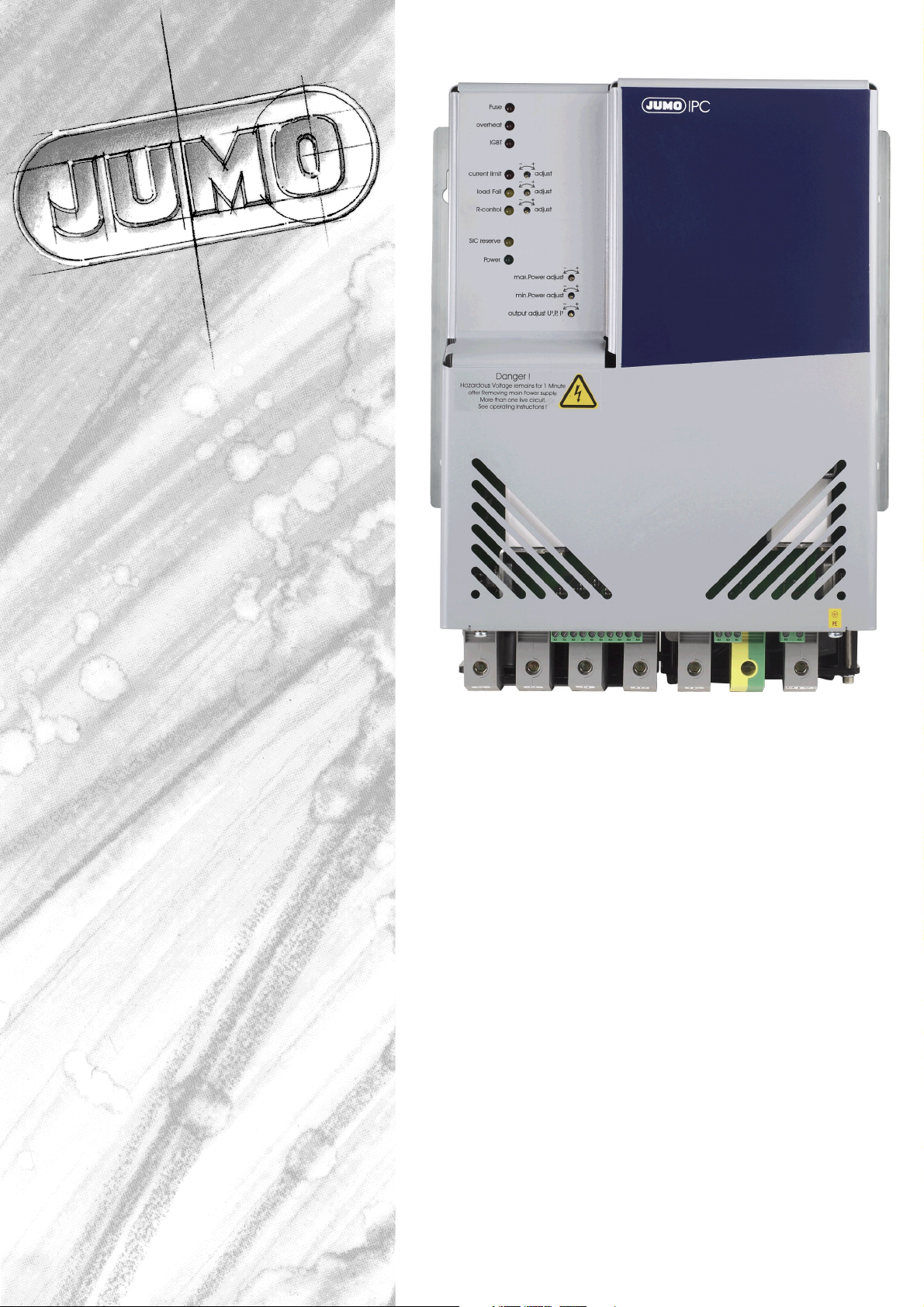
JUMO IGBT-Power Converter
70/100 A with amplitude control
B 70.9050.0.1
Operating Manual
02.08
/00440431
Page 2

Page 3

1 Contents
1 Contents ............................................................................................ 3
2 Introduction ....................................................................................... 5
2.1 Preface .................................................................................................................. 5
2.2 Typographical conventions ................................................................................. 6
2.2.1 Warning signs ........................................................................................................ 6
2.2.2 Note signs .............................................................................................................. 6
2.2.3 Performing an action ........................................................................................... 7
2.3 Order details ......................................................................................................... 8
2.3.1 Standard accessories ............................................................................................ 8
2.3.2 Accessories ........................................................................................................... 9
2.4 Brief description ................................................................................................ 10
2.5 Interpretation of the LEDs ................................................................................ 11
3 Installation ....................................................................................... 13
3.1 Important notes on installation ........................................................................ 13
3.1.1 Correctly wire all components ............................................................................. 13
3.2 Filtering and interference suppression ............................................................ 16
3.3 Ambient conditions ........................................................................................... 18
3.4 Spacings ............................................................................................................. 20
3.4.1 Opening the housing ........................................................................................... 21
4 Electrical connection ...................................................................... 23
4.1 Screw connections in the power section ........................................................ 23
4.1.1 Suitable cables and cross-sections ..................................................................... 25
4.1.2 Electrical isolation ................................................................................................ 26
4.1.3 Use of residual current protection devices .......................................................... 26
4.1.4 Replacing the two semiconductor fuses ............................................................. 26
4.1.5 Wiring of the screw terminals .............................................................................. 28
5 Settings ............................................................................................ 31
5.1 Operating principle ............................................................................................ 31
5.2 Setting switches S101, S103, S104, S105, S106 and X106 ............................ 32
5.3 Subordinate control loop .................................................................................. 33
5.4 Load voltage adjustment .................................................................................. 33
5.5 Control inputs .................................................................................................... 34
5.5.1 Combination of external potentiometer and electronic controller ....................... 35
5.6 Firing pulse inhibit ............................................................................................. 36
5.7 Resistance output .............................................................................................. 36
02.08 [IGBT Power Converter 70/100A] 3
Page 4

5.8 Trimmer settings ................................................................................................ 37
5.8.1 Resistance limiting (R-control) ............................................................................. 37
5.8.2 SIC voltage reserve (SIC reserve) ........................................................................ 38
5.8.3 Control input adjustment (max. Power adjust) .................................................... 38
5.8.4 Setting for maximum power (max. Power adjust) ............................................... 39
5.8.5 Input signal attenuation ....................................................................................... 39
5.9 Setting the base load (min. Power adjust) ...................................................... 39
5.10 Setting the current limit (max. current adjust) ................................................ 40
5.11 Total and partial load failure monitoring (load fail adjust) ............................. 40
5.11.1 Setting the load fault indication ........................................................................... 42
5.12 Safety cut-out in the power section ................................................................. 43
5.13 Adjusting the output level signal (output adjust U2, P , I2 ) ............................ 43
6 Technical data ................................................................................. 45
6.1 Voltage supply .................................................................................................... 45
6.2 Control ................................................................................................................ 45
6.3 Fault signal output ............................................................................................. 45
6.4 General characteristics ..................................................................................... 45
6.5 Choke data ......................................................................................................... 47
6.6 EMC filter ............................................................................................................ 47
7 Troubleshooting .............................................................................. 49
4 [IGBT Power Converter 70/100A] 02.08
Page 5

2.1 Preface
B
A
H
2 Introduction
Please read this operating manual before commissioning the instrument. Keep
the operating manual in a place accessible to all users at all times.
Your comments are appreciated and may assist us in improving this operating
manual.
Phone: +49 661 6003 -727
Fax +49 (0)661 6003-508
The IPC must only be used with the original JUMO choke and an original
JUMO supply filter.
Please check that the chosen supply filter is adequate for the maximum
current drawn from the electrical supply to avoid it being overloaded.
All necessary settings are described in this operating manual.
Manipulations not described in the manual or expressly forbidden will
jeopardise your warranty rights.
Please contact the nearest subsidiary or the head office, should you encounter
problems.
Service hotline For technical questions
Phone support in Germany:
Phone: +49 (0)661 6003-300 or -653 or -899
Fax: +49 661 6003 -881729
E-mail: service@jumo.net
Austria:
Phone: +43 1 610610
Fax: +43 1 6106140
E-mail: info@jumo.at
Switzerland:
Phone: +41 1 928 24 44
Fax: +41 1 928 24 48
E-mail: info@jumo.ch
When accessing the inner parts of the unit and returning controller modules,
E
assemblies or components, please observe the regulations according to DIN
EN 61340-5-1 and DIN EN 61340-5-2 „Protection of electrostatic sensitive
devices“. Only use ESD packaging for transport.
Please note that we cannot accept any liability for damage caused by ESD.
ESD=Electro Static Discharge
02.08 [IGBT Power Converter 70/100A] 5
Page 6

2 Introduction
2.2 Typographical conventions
2.2.1 Warning signs
Danger
This symbol is used when there may be danger to personnel if the
instructions are ignored or not followed correctly!
V
Caution:
This symbol is used when there may be damage to equipment or
A
ESD
data if the instructions are ignored or not followed correctly!
This symbol is used where special care is required when handling
components liable to damage through electrostatic discharge.
E
2.2.2 Note signs
Note
Reference
Footnote
H
v
1
abc
This symbol is used when your special attention is drawn to a
remark.
This symbol refers to further information in other manuals,
chapters or sections.
Footnotes are remarks that refer to specific points in the text.
Footnotes consist of two parts:
A marker in the text and the foot note text itself.
The markers in the text are arranged as continuous superscript
numbers.
6 [IGBT Power Converter 70/100A] 02.08
Page 7

2.2.3 Performing an action
Action
instruction
Vital text
h Plug in the
connector
B
2 Introduction
This symbol indicates that an action to be performed is
described. The individual steps are marked by this asterisk.
This text contains important information, and it is vital that you
read it before going any further.
02.08 [IGBT Power Converter 70/100A] 7
Page 8
2 Introduction
2.3 Order details
The nameplate is glued onto the right panel of the housing.
x
x
x
x
x
(1) Basic version
709050/82
709050/92 Customer-specific version
11 115V AC +15/-20%, 48 ... 63Hz
xx 12 230V AC +15/-20%, 48 ... 63Hz
115 115V AC +15/-20%, 48 ... 63Hz
x 230 230V AC +15/-20%, 48 ... 63Hz
x 400 400V AC +15/-20%, 48 ... 63Hz
x x 020
x x 060
x x 090
x x 120
x x 150
x x 210
x 270
x 380
IGBT power converter 70 or 100A
(max. load voltage 380V) standard version
(2) Voltage supply to the control section
(only for 115V AC in the power section)
(3) Voltage supply to power section
(4) Load voltage
20V DC
60V DC
90V DC
120V DC
150 V DC
210V DC
270V DC
380V DC
xx 070
x
x
xx 100
x x 252 Relay (changeover contact) 3A
x
x
x x 257 Optocoupler Ic
Order code - - - -/
Order example 709050/82 - 12 - 230 - 150 - 100 / 252
2.3.1 Standard accessories
1 Operating Manual
(5) Load current
70A DC
100A DC
(6) Extra code for fault signal output
= 2mA, U
max.
(1) (2) (3) (4) (5) (6)
CEO max.
= 32V
8 [IGBT Power Converter 70/100A] 02.08
Page 9

2.3.2 Accessories
2 Introduction
Choke: L=0.6mH/I
= 100A, protection rating IP 20, as per EN 60 529
N
Dimensions Connection
Height: 208 mm
Width: 200 x 200 mm
Via screw terminals
up to max. 10...50
2
mm
Choke: L=0.6mH/I
= 75A, protection rating IP 20, as per EN 60 529
N
Dimensions Connection cross-
section
Diameter: 155 mm
Height: 135 mm
Diameter of fixing
hole: 10.4 mm
Via screw terminals
up to max. 4...25 mm
2
EMC filter
For voltage supply to power section
Nominal voltage,
nominal current
115V/250V/440V
AC,
I
= 16A
Nom
115V/250V/440V AC,
= 20A
I
Nom
115V/250V/440V
AC,
I
= 32A
Nom
115V/250V/440V
AC,
I
= 63A
Nom
115V/250V/440V
AC,
I
= 100A
Nom
For voltage supply to the control section
115V/250V AC,
= 1A
I
Nom
Dimensions
(L x W x H)
(255 x 60 x 130) mm 0.6 ... 0.8 Nm approx.
(289 x 70 x 140) mm 1.5 ... 1.8 Nm approx. 5.5
(324 x 90 x 160) mm 1.5 ... 1.8 Nm approx.
(380 x 117 x 190) mm 2 ... 2.3 Nm approx.
(445 x 150 x 220) mm 6 ... 8 Nm approx. 26
80 x 45 x 30 mm - approx.
Tightening torque
for
screw terminals
Tightening torque
for screw terminals
max. 6...8 Nm approx.
Tightening torque
for screw terminals
max. 4...4.5 Nm approx.
Weight Sales No.
20kgs
Weight Sales No.
7.5 kgs
Weight Permissibl
4kgs
kgs
9.5kgs
17kgs
kgs
120g
70/00415759
70/00392474
Sales
e ambient
temperatu
No.
re
40°C 70/00399527
40°C 70/00438775
40°C 70/00409831
40°C 70/00409990
40°C 70/00431997
40°C 70/00413620
Semiconductor fuse
2 extra fast semiconductor fuses are installed in the converter, to protect the
IPC in the event of an earth short.
2
The I
t value of the semiconductor fuse must be less than 20000 A2s!
Sales No. 70/00434229
02.08 [IGBT Power Converter 70/100A] 9
Page 10

2 Introduction
2.4 Brief description
Instrument The J IPC is a IGBT power converter for controlling heater loads that
previously required a transformer (either a variable transformer or a
combination of transformer and thyristor power unit).
Its function is that of an electronic transformer with a pulsed DC output.
Advantages It combines the advantages of a conventional variable transformer, such as
amplitude control which is the sinusoidal current loading, with the advantages
of a thyristor power switch, such as current limiting, load monitoring,
subordinate control action, etc.
There is no electrical isolation between the voltage supply and the
A
Application This power converter is employed wherever large resistive loads need to be
load voltage.
switched and no electrical isolation is required between the supply voltage
and the load voltage. Thanks to the amplitude control (the current drawn from
the supply is always sinusoidal), synchronous clock controls (as for burst-firing
operation) and power-factor compensation networks (for the reactive power
resulting from phase-control) are no longer required.
10 [IGBT Power Converter 70/100A] 02.08
Page 11
2 Introduction
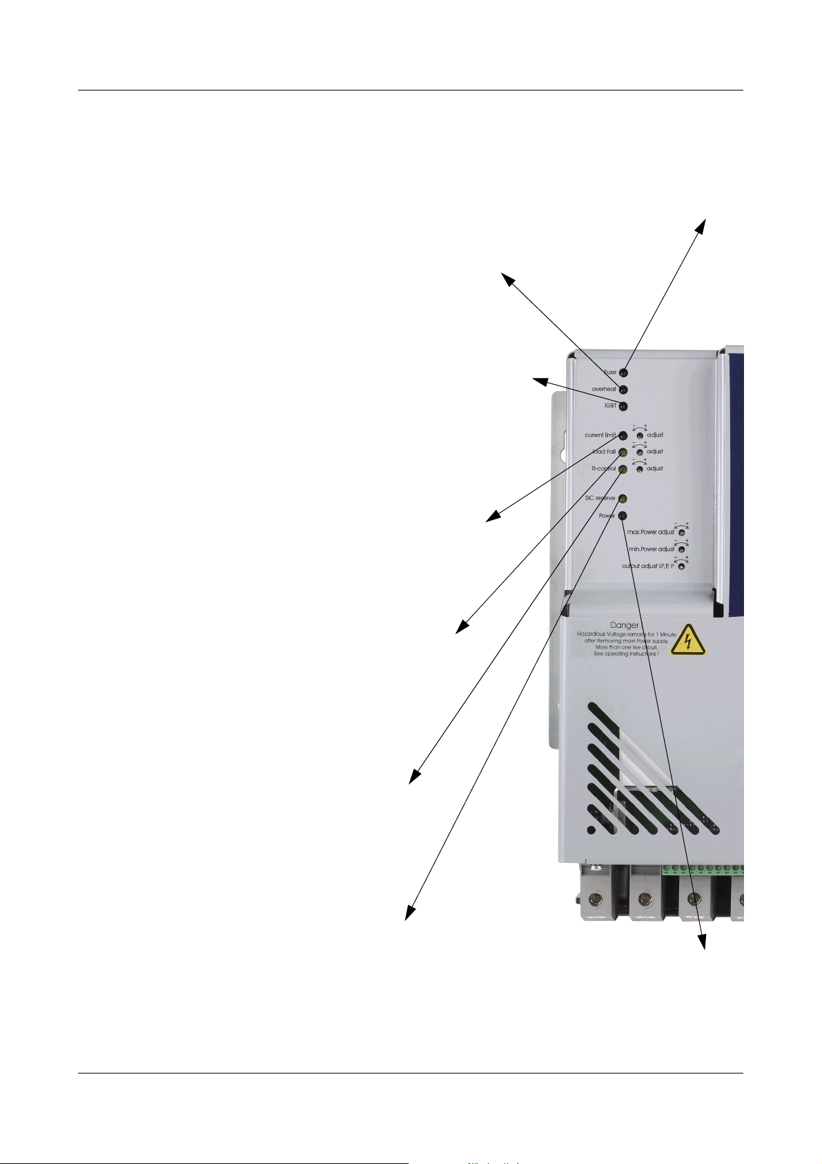
2.5 Interpretation of the LEDs
fuse
Two semiconductor fuses are integrated in the IPC, to protect it in the event of an earth short. If an earth
short occurs, one or both of the semiconductor fuses will trip. Tripping of one or both of the fuses is
indicated by the "Fuse" LED and the drop-out of the fault signal relay.
v Chapter 4.1.4 „Replacing the two semiconductor fuses“
overheat
This LED lights up if the maximum permitted temperature is
exceeded. The fault signal relay drops out at the same time.
The load output remains disconnected until the temperature has
fallen below the limit value again.
v Chapter 3.3 „Ambient conditions“
IGBT
This LED lights up when the electronic safety cut-out of the load circuit
has tripped.
(e.g. because of a wiring fault).
The safety cut-out remains activated until the IPC has been completely
(all-pole) disconnected from the supply and then switched on again.
The fault signal relay drops out at the same time.
v Chapter 5.12 „Safety cut-out in the power section“
current limit
This LED lights up if the converter is working at the current limit.
v Chapter 5.10 „Setting the current limit (max. current
adjust)“
load fail
This LED lights up if a total or partial load failure has been
detected.
The fault signal relay drops out at the same time.
v Chapter 5.11 „Total and partial load failure
monitoring (load fail adjust)“
R-control
This LED lights up if the converter is working at the
resistance limit.
v Chapter 5.8.1 „Resistance limiting (R-
control)“
SIC reserve
This LED lights up when the IPC has reached its
max. load voltage, so there is no longer
automatic compensation for ageing at SIC load.
The fault signal relay drops out at the same time.
v Chapter 5.8.2 „SIC voltage reserve (SIC
reserve)“
This LED indicates that the control section is
connected to the voltage supply.
It does not indicate the status of the power
section!
Power
02.08 [IGBT Power Converter 70/100A] 11
Page 12

2 Introduction
12 [IGBT Power Converter 70/100A] 02.08
Page 13

3.1 Important notes on installation
3 Installation
Safety
regulations
V
k The choice of cable, the installation and the electrical connection of the
instrument must conform to the requirements of VDE 0100 "Regulations on
the Installation of Power Circuits with Nominal Voltages below 1000 V AC"
or the appropriate local regulations.
k The electrical connection must only be carried out by qualified personnel.
k An isolation switch should be wired between the supply and the converter
to be able to disconnect the converter from the voltage supply on all poles
prior to starting internal work.
Caution!
The converter has 2 power supplies (to the control section and to the power
section). Disconnect both supplies (all poles) prior to starting work on the
converter.
Allow 1 minute to elapse after switching off prior to starting work on the
converter, since potentially fatal voltages could be present in the converter
interior and at the terminals.
k Inside the converter, safety gaps meet the requirements for double
insulation.
When installing the connecting cable, ensure that the cables are fitted
according to regulations and that the safety gaps are maintained.
Electrical
supply types
Fuse protection k Fuse protection in accordance with the VDE regulations must be installed
V
The IPC is suitable for operation with TN and TT supply networks.
h Carry out installation in accordance with EN 50178.
for the voltage supply to the power section. The supply protection can also
be achieved by a circuit-breaker in the supply lead. This must be
dimensioned for the power consumption of the power converter and the
rated current of the downstream EMC filter.
k Two semiconductor fuses are incorporated to protect the IPC in the event
of an earth short.
2
(The I
v Chapter 4.1.4 „Replacing the two semiconductor fuses“
k Provide an appropriate control circuit fuse for control section lead
protection. The control section consumes approx. 75 VA.
t value of the semiconductor fuse must be smaller than 20000 A2s)!
3.1.1 Correctly wire all components
EMC filter
The IPC may only be used in conjunction with a suitable filter
A
(accessories). If a different filter is used, it must be of equal or better
characteristics. Otherwise, inductive voltages may be introduced into
the supply network. We decline any liability for damage caused as a
result.
02.08 [IGBT Power Converter 70/100A] 13
Page 14
3 Installation
The EMC filters may only be used for interference suppression of the
H
The earth leakage current of the IPC power converter with a filter wired into the
supply lead is less than 3 mA. If the load conditions result in an earth leakage
current greater than 3.5 mA, a fixed supply connection is required as a
protection against hazardous potentials (also see EN 50178).
Electromagnetic compatibility conforms to the standards and regulations cited
in the technical data.
v Chapter 6 „Technical data“
h Load wiring (thick) and cables for control inputs (thin) should be routed
14 [IGBT Power Converter 70/100A] 02.08
IPC power converter. Other devices, such as controllers, power
supplies etc. must be suppressed, where necessary, with their own
EMC filters. Do not wire these devices in parallel to the IPC power
converter on the load side of the EMC filter.
separately, if possible.
Page 15

3 Installation
Positioning of
the choke
Connection h Check the data given on the nameplate (voltage supply to the control
PE connection/
FB connection
Choke
connection
h The choke should be installed close to the converter.
section, voltage supply to the power section, load voltage and load current)
against the system data.
v Chapter 2.3 „Order details“
h Check the adaptation of the setpoint inputs.
h Check the switch settings.
h Provide a direct connection between the PE of the IPC and the PE of the
supply network. Connect to the PE terminal
of the IPC.
h If necessary, interference emission of the IPC can also be minimised by a
function equipotential bonding. The function equipotential bonding is
connected to the FB terminal of the IPC.
v Chapter 3.1.1 „Correctly wire all components“
h The choke is connected to terminals C and 1C.
Voltage
supply
Load
connection
h Connect the voltage supply to the control section to terminals L1 and N(L2)
(X109).
h Connect the voltage supply of the power section to terminals U and N(V).
An isolation switch should be wired between the supply and the
A
h The load is connected to terminals D and 1D.
h The cable between the load and the IPC should be as short as possible and
not exceed 50 m.
A
converter to be able to disconnect the converter from the voltage
supply on all poles prior to starting internal work!
The connection must only be carried out by qualified personnel!
Use a shielded cable to connect to the load, ensure that the
shielding is connected to earth on both ends.
v Chapter 3.2 „Filtering and interference suppression“
Choosing the suitable cables
v Chapter 4.1.1 „Suitable cables and cross-sections“
Control inputs The terminal strip for control connections (inputs and outputs) have been laid
out for safe isolation from the supply (SELV). To prevent the safe isolation from
being impaired, ensure that all connected current circuits are also safely
isolated. The required auxiliary supplies must be SELV voltages.
02.08 [IGBT Power Converter 70/100A] 15
Page 16

3 Installation
Switch-on
sequence
The voltage supplies to the control section and to the power section must be
switched on simultaneously.
Under no circumstances may the voltage supply to the control
H
section be switched on before the load voltage. This is especially
important when operating resistive loads that have a high hot/cold
resistance ratio.
3.2 Filtering and interference suppression
System Compliance with the EMC standards can only be achieved through additional
EMC measures.
These include:
- a supply filter in the voltage supply
- a shielded cable for the voltage supply (from the supply filter (load) to the
IPC)
- a shielded cable to the load
- Functional equipotential bonding
Compliance with the EMC standards must be tested for the overall system.
Construction To keep interference emission through conducted and radiated interference
below the permissible levels defined in the pertinent EMC standards,
constructive measures must be taken in the installation and wiring stages in
addition to supply input filtering. Poor earth connection or shielding of the
EMC filter will reduce the effectiveness of the interference suppression
measures.
The following points should be noted in order to achieve good configuration
for EMC purposes:
h All metallic components of the converter or cabinet must be well bonded
for HF currents over a large surface area.
h The EMC filter should be installed close to the IPC, if possible, on a
common metal plate. Route cables for control inputs and signal cables as
far apart from each other as possible, and use shielded cables.
h If possible, do not route power cables in the same cable duct as control or
signal cables.
h The cable between the load and the IPC should be as short as possible and
not exceed 50 m.
Earthing The base plate, the supply filter and the shielding of the supply cable must be
earthed to a star point using HF braiding.
Choosing
a suitable
cable
k If the cable between the filter and the IPC is longer than 300 mm, we
recommend to use a shielded cable with the shielding earthed at both
ends. Route cables inside the switch cabinet as close as possible to
grounded surfaces, otherwise they can act as antennae and radiate
interference.
16 [IGBT Power Converter 70/100A] 02.08
Page 17

3 Installation
k To achieve a good shielding effect for the cable, only use cables that have
shielding made with tinned or nickel-plated copper braiding. The coverage
of the shielding should be at least 70%; the lay angle should be 90°.
Screens made of steel braiding are not suitable. Earth the shielding of the
load cable on both ends.
k The shielding of the control inputs must only be earthed at one end (IPC
side). If potential differences exist, install an additional equipotential
bonding conductor.
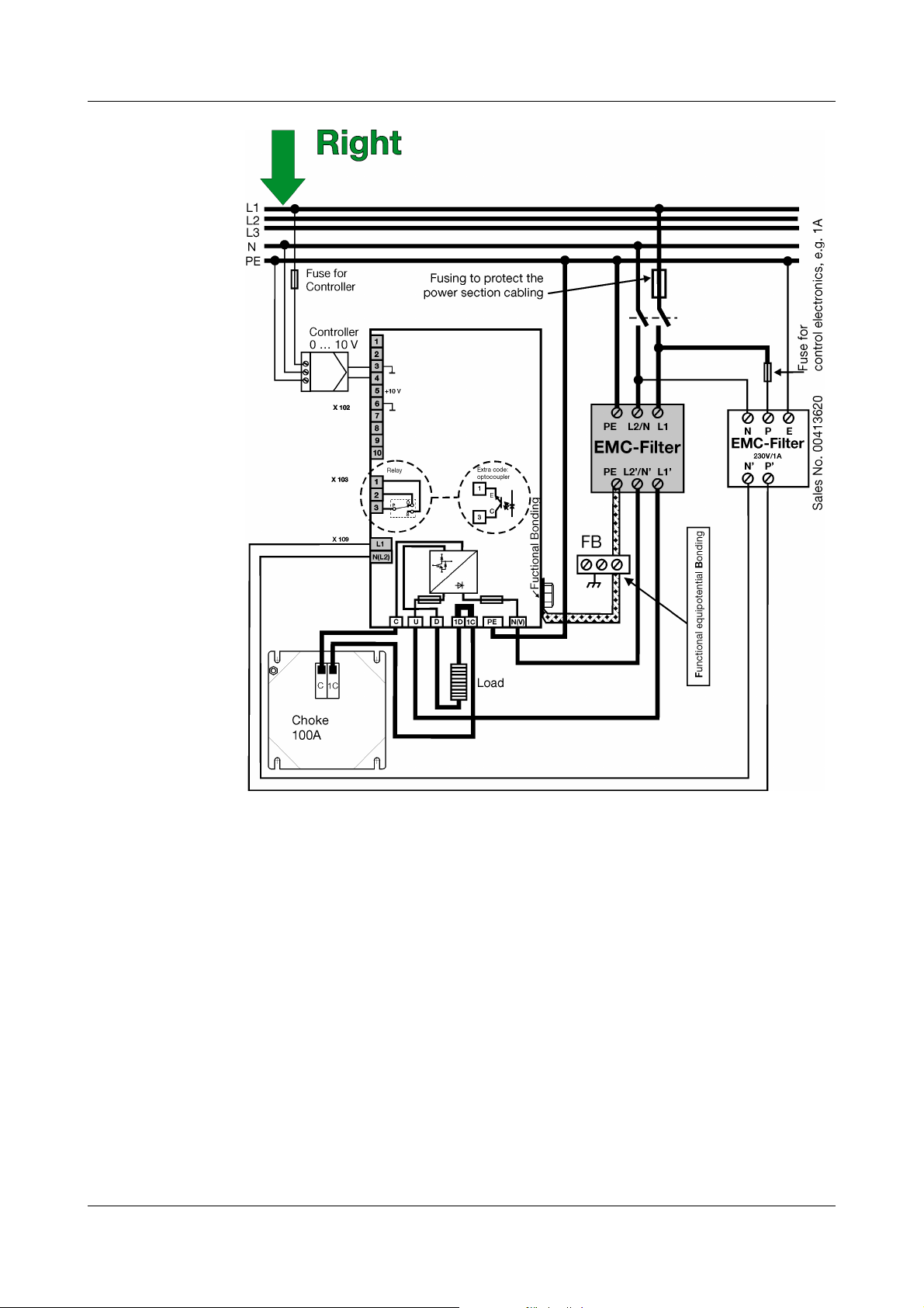
EMV compliant
design
The user/owner is responsible for compliance of the specific application with
the EMC directive. The diagram below illustrates such a design for type
709050/X2-12-400-XXX-100/XXX with a Phase / Phase supply configuration.
02.08 [IGBT Power Converter 70/100A] 17
Page 18

3 Installation
3.3 Ambient conditions
Misuse The instrument is not suitable for use in areas with an explosion hazard (Ex
areas).
Mounting site The installation site should be free from vibration, dust and corrosive media.
Climatic
conditions
Power loss Power loss occurs in the form of thermal discharge at the cooling body of the
- Relative humidity: 5...85 % no condensation (3K3 as per EN 60721)
- Max. air inlet temperature 35°C
- Ambient temperature range: 5 ... 40 °C (3K3 as per EN 60721)
- Storage temperature range: -10...70 °C
power converter and has to be discharged at the place of installation (e.g. in
the switch cabinet) in accordance with the climatic conditions.
Example of the
Molybdenum
Disilicid
heating
elements
IPC type: 709050/82-12-400-150-100/252
Load voltage = 150V
Load current = 100A
Voltage supply to the power section = 400V
Resistive loads and Molybdenum Disilicid heating elements:
Heating element data: Load voltage = 140V; load current = 90A
h Determine the max. load voltage actually taken (e.g. 140 V) and find the
point intersecting with the curve for the voltage supply in the power section.
The Y axis shows the attendant power loss factor of, e.g., 8.5.
The power loss (W) is obtained by multiplying this power loss factor by the
load current (e.g. 90A)
18 [IGBT Power Converter 70/100A] 02.08
Page 19

3 Installation
that flows at max. load voltage (e.g. 140V) through the load resistor
Power loss = 90(A) x power loss factor
Power loss = 90(A) x 8.5 = 765W
Example of the
SIC heating
elements
Wall
fixing
IPC type: 709050/92-12-400-150-100/252
Load voltage = 150V
Load current = 100A
Voltage supply to the power section = 400V
P control, P = 6300W
SIC heating elements
SIC heating element data: new: 70V/90A, old 140V/45A; P = 6300W
h Determine the maximum load voltage actually (e.g. 70V) of the new SIC
heating element and find the point intersecting with the curve for the
voltage supply in the power section. The Y axis shows the attendant power
loss factor of, e.g., 6.8.
The power loss (W) is obtained by multiplying this power loss factor by the
load current (e.g. 90A)
that flows at max. load voltage (e.g. 70V) through the new SIC heating element
Power loss = 90(A) x power loss factor
Power loss = 90(A) x 6.8 = 612W
h Use 4 hexagonal M6 bolts (at least quality 8.8) to fix the converter vertically
on a heat-resistant switch cabinet back panel.
H
The temperature of the air drawn in through the ventilation grille
must not exceed 35° C. Ensure that the inlet air for the built-in
ventilators can be taken in from below and escape at the top
without obstruction!
02.08 [IGBT Power Converter 70/100A] 19
Page 20

3 Installation
V
Dimensions Type 709050/X2...
3.4 Spacings
Caution! Hot cooling body!
The cooling body can reach very high temperatures during
operation!
h Allow a clearance of 10 cm from the floor.
h Allow a clearance of 15 cm from the ceiling.
h When fitted next to each other, no spacing between the units is required.
20 [IGBT Power Converter 70/100A] 02.08
Page 21

3.4.1 Opening the housing
Caution!
V
The converter has 2 power supplies (to the control section and to the power
section). Disconnect both supplies (all poles) prior to starting work on the
converter.
Allow 1 minute to elapse after switching off prior to starting work on the
converter, since potentially fatal voltages could be present in the converter
interior and at the terminals.
Caution! Hot cooling body!
h Disconnect the built-in converter from the voltage supply on all poles
h Wait for 1 minute
h Check that no voltage is present
h Undo the 2 screws from the bottom of the converter
3 Installation
h Swing up the housing cover from the bottom of the converter
02.08 [IGBT Power Converter 70/100A] 21
Page 22

3 Installation
h Lift the cover out of the groove and take it off forward
22 [IGBT Power Converter 70/100A] 02.08
Page 23

4 Electrical connection
V
4.1 Screw connections in the power section
Tool - Screwdriver
- Allen key, width across flats 5 mm
The electrical connection must only be carried out by qualified
personnel!
h Disconnect the system from the electrical supply on all poles.
h Make the connections to the screw terminals in the power section using
cable lugs and cable cross sections from 10 to 50mm
Maximum tightening torque from 6 to 8 Nm.
2
.
02.08 [IGBT Power Converter 70/100A] 23
Page 24

4 Electrical connection
Phase / N The diagram shows the wiring for single-phase operation Phase / N for
type 709050/X2.
I
Phase / Phase The diagram shows the wiring for single-phase operation Phase / Phase for
type 709050/X2.
24 [IGBT Power Converter 70/100A] 02.08
Page 25

4 Electrical connection
4.1.1 Suitable cables and cross-sections
PE conductor The cross-section of the PE conductor must be at least as large as the cross-
section of the voltage supply conductors to the power section. If the
protective earth (PE) conductor is not part of the supply cable or its sheathing,
the chosen conductor must have a cross-section of at least 2.5 mm
2
mechanically protected) or at least 4mm
mechanically protected).
v see VDE 0100 Part 540
Control section The screw terminals for the voltage supply to the control section are laid out
for a conductor cross-section between 0.5mm
conductor cross-section must not be less than 0.5
must correspond to the selected conductor cross-section.
Power consumption is approx. 75 VA.
Power section
The minimum conductor cross-section chosen must be adequate
H
for the maximum conductor current. The electrical connection is
made via screw terminals on the converter. We recommend the use
of a shielded cable to reduce EMC interference emission.
(if the PE conductor is not
2
and 2.5mm2. The minimum
2
mm. Fusing of the cable
2
(if
Calculation
formula
Example
A
I
I
I
Supply
Supply
Supply
v Chapter 3.2 „Filtering and interference suppression“ Choosing
the suitable cables
The cable cross-section in the load and choke circuits must not be
smaller than the cross-section of the supply leads to the power
section!
=
=
=
maximum load power consumption
+ 2A
Voltage supply to power section
3000 W (heater load)
+ 2A =
230V (voltage supply to the power section)
13A + 2A = 15A
02.08 [IGBT Power Converter 70/100A] 25
Page 26

4 Electrical connection
4.1.2 Electrical isolation
The control section, including the inputs and outputs, as well as all operator
controls can be connected to SELV circuits.
The fault signal relay can be connected to SELV or supply potential, without
prejudicing the electrical isolation arrangements of the other inputs and
outputs.
There is no electrical isolation between the voltage supply of the
A
4.1.3 Use of residual current protection devices
The converter is equipped with an internal input rectifier. A short to the housing
can result in a residual DC current that blocks the tripping of the conventional
residual current protection device. For this reason, any RCD used must be an
„all-current sensitive“ version of Type B.
When defining the trip current for the RCD, the leakage currents of the EMC
filter caused by the Y capacitors (<3mA) as well as the capacitive currents
from the cable shielding have to be taken into account.
power section and the load.
Ensure that the metal housing of the oven or combustion chamber
is properly earthed.
v Chapter 3.2 „Filtering and interference suppression“ Installation
must comply with EVC requirements.
See also EN 50178 (VDE 0160):
H
Protection of electrical equipment through residual current
protection devices.
4.1.4 Replacing the two semiconductor fuses
h Disconnect (all poles) the converter from the voltage supply.
h Wait 1 minute to allow hazardous voltages to discharge.
h Check that no voltage is present on the screw terminals.
h Open the housing as described in Chapter 3.4.1 „Opening the housing“.
h Undo 2 screws of the semiconductor fuse, remove fuses from the holder by
turning laterally, and replace with new fuses.
h Tighten the screws with a maximum tightening torque of 20 Nm.
26 [IGBT Power Converter 70/100A] 02.08
Page 27

4 Electrical connection
h Check the cause that led to the semiconductor fuse tripping (e.g. earth
short in the power section).
h Only use original JUMO replacement parts, item No. 70/00434229.
v Chapter 2.3.2 „Accessories“
02.08 [IGBT Power Converter 70/100A] 27
Page 28

4 Electrical connection
4.1.5 Wiring of the screw terminals
Position The following diagram shows the position of the screw connections in the
power section, the screw terminals on the PCB as well as the general
connection arrangement.
Only tighten the green screw terminals in the control section with a
A
tightening torque of 0.5 to 0.6 Nm!
Connection for terminal screw X109 Detail
Voltage supply
Control section
Connection for Screw connections in
Voltage supply to power section U
Protective earth PE
Functional equipotential bonding
v Chapter 3.1.1 „Correctly wire all
components“
28 [IGBT Power Converter 70/100A] 02.08
L1
N (L2)
Detail
the power section
N(V)
FB
Page 29

4 Electrical connection
Choke connection 1C
C
Load connection 1D -
D +
Connection for terminal screw X102 Detail
Current input
(differential input)
12+
Voltage input
(referred to ground)
External manual adjustment
Potentiometer 5 k⍀
Firing pulse inhibit
(inhibit input) I
approx. 1mA
K
3 ground
4+
3 Start (ground)
4 slider
5 end (+10V)
6 ground
7+
(break or make contact)
2
Output level 0 to 10V (U
approx. 2mA
I
max
, P, I2 )
Resistance output 0 to 5 V (R)
approx. 2mA
I
max
10+
6 ground
8 +
6 ground
–
Connection for Screw terminal X103 Detail
Load fault output with relay
contact rating 230V AC/3A
resistive load
1 make contact
2 break contact
3 common
relay drops out at fault
8
+
6
Load fault output with
optocoupler Ic
U
CEO max
= 32 V
max
= 2mA
3 collector
1 emitter
02.08 [IGBT Power Converter 70/100A] 29
Page 30

4 Electrical connection
30 [IGBT Power Converter 70/100A] 02.08
Page 31

5.1 Operating principle
The J IPC can be used wherever a transformer was previously used to
reduce the voltage level.
It functions as an electronic transformer that produces a pulsed DC output.
Block diagram
5 Settings
02.08 [IGBT Power Converter 70/100A] 31
Page 32

5 Settings
5.2 Setting switches S101, S103, S104, S105, S106 and X106
32 [IGBT Power Converter 70/100A] 02.08
Page 33

5.3 Subordinate control loop
Subordinate control loops are primarily used to eliminate or compensate for
external disturbances, such as fluctuations in the supply voltage and
alterations in resistance that have a negative effect on the operation of the
control loop.
2
Factory setting A subordinate U
however, also the P or I
control loop is factory set,
2
control loop is possible.
5 Settings
Control
type
2
U
P 0 1 0 - general application,
2
I
k factory setting
Internal switch S101 Application
S1 S2 S3
1 0 0 - positive TC, Molybdenum Disilicid
0 0 1 - negative TC
5.4 Load voltage adjustment
Switch S101-7 can be used to adjust the load voltage.
If the max. load voltage required is less than 75% of the
load voltage U
If the maximum required load voltage is 75% or more of the nominal load
voltage U
L Nom
as per type code, then S 101-7 must be opened.
L Nom
as per type code, then S 101-7 must be closed.
- R ≈ constant
- brightness controls
required for SIC loads and
automatic compensation for ageing.
Factory setting S101-7 is closed.
02.08 [IGBT Power Converter 70/100A] 33
Page 34

5 Settings
5.5 Control inputs
The internal switches S8, S9 and S104 are used to adapt the converter to the
available control signal (controller output signal).
The voltage and current inputs are separated from one another. The current
inputs (+,-) are arranged as differential inputs, i.e. they can have a maximum
common mode voltage of 7V with respect to the common ground potential (⊥).
If the current and voltage inputs are used at the same time, their effect will be
cumulative.
Control signal Internal switches
Signal start Signal end S8 S9 S104
0 mA 20 mA 0 1 1
4 mA 20 mA 0 0 2
0 V 10 V 0 1 1
2 V 10 V 0 0 2
0 V 5 V 1 1 1
1 V 5 V 1 0 2
k factory setting
Analog
control inputs
The converter can be controlled through the following signals
(continuous power control):
- voltage signal (terminals 3, 4)
- current signal (terminals 1, 2)
-5 kΩ potentiometer (terminals 3, 4, 5)
For this purpose, a 10 V source is provided on terminal 5.
(switch settings are as for a 0 ... 10 V signal)
34 [IGBT Power Converter 70/100A] 02.08
Page 35

5 Settings
5.5.1 Combination of external potentiometer and electronic controller
Controller with
current output
The voltage input (terminals 3, 4) in conjunction with the internal 10 V source
and a 5 kΩ potentiometer is used as a manual control input.
Switch S
a
S
b
Controller with
voltage output
Automatic mode open open
Manual mode closed closed
To prevent unintended oversteering when switching over to the
H
Only the voltage input of the converter is used. Manual operation requires a 5
kΩ potentiometer connected to terminals 3 and 5.
Switch S
Automatic mode Position 1
Manual mode Position 2
manual mode, S
both signals will briefly cumulate.
should be mechanically linked to Sb. Otherwise
a
c
02.08 [IGBT Power Converter 70/100A] 35
Page 36

5 Settings
5.6 Firing pulse inhibit
The firing pulse inhibit function provides a simple way of switching
to high power levels.
In order to be able to disconnect a system from the supply voltage,
V
A
A contact between connections 6 and 7 can be used to switch off the load.
The external contact can be a make or break contact, depending on the
position of S105.
a circuit-breaker or main switch for all-pole disconnection must be
wired into the supply feed!
If the output power is simply removed by inhibiting the firing
pulses, this does not provide electrical isolation from the voltage
supply! The terminals D or 1D may still carry dangerous voltage
from the supply.
External contact Internal switch S 105 Response
Make (a) Position 1 The Load is permanently
Break (b) Position 2 The Load is permanently
k factory setting
Factory setting S105 is in position 1
5.7 Resistance output
When the converter is operating within rated limits, the resistance output has a
voltage of 4 ... 5 V.
switched off when the contact
is closed
switched off when the contact
is open
36 [IGBT Power Converter 70/100A] 02.08
Page 37

5.8 Trimmer settings
The converter has 6 trimmers that can be adjusted by inserting a screwdriver
blade (maximum blade width: 2 mm) through openings in the housing.
current limit adjust
load fail adjust
resistance control adjust
max. Power adjust
min. Power adjust
output adjust P I
5 Settings
2
2
U , ,
5.8.1 Resistance limiting (R-control)
The switch S101-10 can be used to activate a limiting of the output power
depending on the resistance value R when operating Molybdenum Disilicid
heating elements, to avoid overheating of the elements in the upper
temperature range. Direct measurement of the resistance of the elements
allows precise determination of the element temperature. When switch S10110 is closed, the converter limits its output power as soon as the element
resistance (the element temperature) is reached that was set by the trimmer for
„resistance control adjust“. In this manner, the heating element is protected
from overheating. The "R-control" LED signals the active status of the
resistance limiting.
Factory setting The R-control trimmer is not factory-set. An appropriate adjustment must be
carried out on site to set the maximum temperature limit for the heating
element. This can be carried out with the aid of load voltage and current
measurement (resistance measurement) or with the help of a thermal imaging
camera.
A true-rms meter must be used for measuring voltage, power or
A
current, because the load current is pulsating DC.
A meter calibrated for alternating current (AC) and sinusoidal
waveforms will produce false readings!
02.08 [IGBT Power Converter 70/100A] 37
Page 38

5 Settings
The adjustment range of the resistance limiting can be set by the R-control
trimmer between R
= nominal voltage / nominal current
R
Nom
Action Response
Turn „resistance control“
trimmer clockwise
Turn „resistance control“
trimmer counter-clockwise
Factory setting S101-10 is open, R-control is inactive
5.8.2 SIC voltage reserve (SIC reserve)
When SIC heating elements are used, ageing of the elements is automatically
compensated for when P-control is chosen for the subordinate control loop
(Chapter 5.3).
The resistance of the SIC heating element increases with the operational time.
The IPC converter adjusts the load voltage automatically to match the required
power output. As soon as the maximum load voltage from the IPC is no longer
sufficient to produce the required output power for the SIC heating element,
this condition will be signaled by the „SIC reserve“ LED. This indication
appears time delayed after approx. 7 minutes.
The fault signal relay drops out at the same time.
and 10xR
Nom
Nom
.
Limiting at a higher resistance value
(higher temperature)
Limiting at a lower resistance value
(lower temperature)
The SIC reserve display as well as the fault signal function can be activated by
opening the S101-12.
Factory setting S101-12 is closed, and the function is inactive.
5.8.3 Control input adjustment (max. Power adjust)
The „max. Power adjust“ trimmer at the front can be used to adapt the power
output of the converter to the maximum output signal of the controller
connected before.
Action Response
Turn the „max. Power adjust“ trimmer
clockwise
Turn the „max. Power adjust“ trimmer
counter-clockwise
Factory setting The trimmer is adjusted so that a 100% controller output signal produces the
2
maximum load voltage (U
control loop).
control is the factory setting for the subordinate
more power
less power
38 [IGBT Power Converter 70/100A] 02.08
Page 39

Correct
measurement
A
A true-rms meter must be used for measuring voltage, power or
current, because the load current is pulsating DC.
A meter calibrated for alternating current (AC) and sinusoidal
waveforms will produce false readings!
5.8.4 Setting for maximum power (max. Power adjust)
h Apply the maximum controller output signal
h Turn the „max. Power adjust“ trimmer clockwise or counter-clockwise until
the required power is achieved.
h Turning the „max. Power adjust“ trimmer clockwise will increase the
maximum power output.
h Take care that the red „current limit“ LED remains off, otherwise the circuit
is operating in current limiting (current limit), which leaves turning the
trimmer clockwise without effect, as the power output will not increase.
5.8.5 Input signal attenuation
5 Settings
h Turning the „max. Power adjust“ trimmer counter-clockwise will decrease
the maximum power output of the converter.
5.9 Setting the base load (min. Power adjust)
Base load
setting
Example: A heating system is operated with a base load set to 1/3. The remaining 2/3 of
Correct
measurement
Open switch S11 to be able to set a base load.
Turning the „min. Power adjust“ trimmer clockwise will increase the base load
setting.
The settable range covers the complete range from 0 to 100%.
the power are regulated by the controller.
A true-rms meter must be used for measuring voltage, power or
A
current, because the load current is pulsating DC.
A meter calibrated for alternating current (AC) and sinusoidal
waveforms will produce false readings!
Factory setting S101-11 is closed, no base load is set
02.08 [IGBT Power Converter 70/100A] 39
Page 40

5 Settings
5.10 Setting the current limit (max. current adjust)
h The front „max. current adjust“ trimmer can be used to limit the rms value
of the load current over a range of 10 to 100% of the rated converter
current.
1.5 clockwise turns correspond to increasing the response threshold by
approx. 10% of the rated converter current.
Action Response
Correct
measurement
Turn the „max. current
adjust“ trimmer clockwise
Turn the „max. current
adjust“ trimmer counterclockwise
A true-rms meter must be used for measuring voltage, power or
A
current, because the load current is pulsating DC.
A meter calibrated for alternating current (AC) and sinusoidal
waveforms will produce false readings!
The current limit will increase
The current limit will reduce
The red „current limit“ LED is on when current limiting is active.
Factory setting The trimmer is set to the maximum rated current.
H
The activation of the current limit can also be used to operate the
fault signal relay.
For this purpose, open switch S 101/13.
Factory setting: The activated current limit is only indicated by the red
LED ( S 101/13 closed)
v Chapter 5.2 „Setting switches S101, S103, S104, S105, S106 and
X106“
5.11 Total and partial load failure monitoring (load fail adjust)
Total and partial load failure monitoring for different types of load.
The factory setting of the converter is such that the total and partial load failure
states can be detected for resistive loads and loads connected in series. For
short-wave infrared radiators, turn switch S106 to position 2.
Factory setting Switch S106 is in position 1
If the load resistance changes during operation, this will be detected by the
partial load monitoring and indicated through the signal output.
The response threshold can be adjusted by the „load fail adjust“ trimmer on
the front panel (load fail adjust) between 20 and 100% of the rated converter
current.
40 [IGBT Power Converter 70/100A] 02.08
Page 41

The smallest change in resistance that can be detected is 5 % of
H
Factory setting The trimmer is set to approx. 20 %.
The signal output provided is a floating contact or an optocoupler, depending
on the extra code.
Typ e : re lay
709050 / X2 - XX - XXX - XXX - XXX / 252
Typ e :
optocoupler
709050 / X2 - XX - XXX - XXX - XXX / 257
In the case of a load fault, the floating contact drops out, or the collectoremitter path of the optocoupler goes high-resistance.
The signal output is also active if the maximum temperature of the converter is
exceeded (overheat), if the safety cut-out in the power section has been
triggered or if the semiconductor fuse has blown (fuse).
the nominal load resistance.
5 Settings
H
v Chapter „“
Jumper setting Response
k factory setting
H
The functions „SIC voltage reserve exhausted“ or „Current limit
active“ can also be applied to the signal output if they are activated
as described in the following sections:
v Chapter 5.8.2 „SIC voltage reserve (SIC reserve)“
v Chapter 5.10 „Setting the current limit (max. current adjust)“
Underload detection
Overload detection
The total and partial load failure monitoring (underload) also allows
overload monitoring. For this purpose, both jumpers on the pin
strip X106 must be turned through 90°.
v Chapter 5.2 „Setting switches S101, S103, S104, S105, S106
and X106“
02.08 [IGBT Power Converter 70/100A] 41
Page 42

5 Settings
5.11.1 Setting the load fault indication
The partial load setting must be made after the current limit has
H
h Connect the load
h Provide a full control signal (e.g. 20 mA at the control input)
h Adjust the „load fail adjust“ trimmer such that the yellow „load fail“ LED just
extinguishes.
- Turn clockwise = LED lights up
- Turn counter-clockwise = LED extinguishes
h If necessary, continue turning counter-clockwise to reduce the activation
threshold. 1.5 turns of the potentiometer change the load current by
approx. 10% of the converter rated current.
been set. If the current limit setting is changed, this will also affect
the setting of the partial load fault detection.
This must be corrected accordingly, if necessary.
Alternative
setting option:
To simulate a load fail, adjust the „load fail adjust“ trimmer such that the yellow
„load fail“ LED lights up.
The smallest change in resistance that can be detected is 5 % of the
H
nominal load resistance.
42 [IGBT Power Converter 70/100A] 02.08
Page 43

5 Settings
5.12 Safety cut-out in the power section
If there is a fault in the choke or the control electronics, the output voltage is
switched off between terminals D and 1D.
However, terminals D and 1D may still carry dangerous voltage from
A
This state is indicated by the „IGBT“ LED, and the fault signal relay drops out.
This safety cut-out remains activated even when the fault has been remedied.
It can only be reset by disconnecting the voltage supply.
h Switch the device off briefly, and then on again
5.13 Adjusting the output level signal (output adjust U2, P , I2 )
In the factory settings, the output level signal corresponds to the I2 signal at
the output of the converter. It is thus proportional to the power in the load
(R=constant).
the supply. They are not electrically isolated from the supply!
Output adjust
2
, P, I
2
U
However, setting P or U
v Chapter 5.2 „Setting switches S101, S103, S104, S105, S106 and X106“
Power level output Internal switches
2
U
P010
2
I
The output level signal provides a voltage in the range of 0 to 10V
(corresponding to 0 to 100% of the variable being measured). The trimmer
„output adjust U
end value:
Action Response
Tur n „o utput adjust U
clockwise
Tur n „o utput adjust U
counter-clockwise
2
2
instead of the I2 signals is also possible
S4 S5 S6
100
001
, P , I2 “ on the front panel can be used to set the required
2
, P , I2 “ trimmer
2
, P , I2 “ trimmer
End value increases
End value reduces
02.08 [IGBT Power Converter 70/100A] 43
Page 44

5 Settings
44 [IGBT Power Converter 70/100A] 02.08
Page 45

6.1 Voltage supply
6 Technical data
Voltage supply
Power section
Voltage supply
Control section
Power consumption, control section approx. 75 VA
Load voltage U
Load current U
Load type Resistive loads
L rms
L rms
115V AC +15%/-20% 48 ... 63Hz
230V AC +15%/-20% 48 … 63Hz
400V AC +15%/-20% 48 … 63Hz
115V AC +15%/-20% 48 ... 63Hz, (only with 115V AC in the power
section)
230V AC +15%/-20% 48 … 63Hz
20 V DC, 60 V, 90V, 120 V, 150 V, 210 V, 270V, 380V
70, 100A DC
6.2 Control
Control signal 0 (4) … 20mA Ri = 50 Ω
0 (2) … 10V R
0 (1) … 5V R
Manual control through an external 5 kΩ potentiometer
Input signal attenuation Adjustment range 100 to 20%
Base load setting 0 ... 100 %
= 25kΩ
i
= 12kΩ
i
6.3 Fault signal output
Relay (changeover contact)
without contact suppression
Optocoupler output I
150000 switching actions at a contact rating of 3A/230V 50Hz (resistive
load)
Cmax
= 2mA, U
CEOmax
= 32V
6.4 General characteristics
Circuit variants Single-phase operation
Operating modes Amplitude control
Subordinate
control
Current limiting In operation, the load current can be set in the range of 10 … 100% I
Partial load failure 20 ... 100% of nominal current
R-control Adjustment range from R
Power level output As standard: free choice between U
As standard: free choice between U
trimmer on the front panel. This limits the rms-value of the load current.
to 10x R
R
= nominal voltage / nominal current
Nom
adjustable 0 … 5V to 0 … 10V , I
offset deviation: ≤ ± 5%
Nom
2
-, P-, I2 control via internal switches
Nom
2
-, P-, or I2 signal via internal switches,
≈ 2mA,
max
by a
N
02.08 [IGBT Power Converter 70/100A] 45
Page 46

6 Technical data
Power loss P
(W) It occurs in the form of thermal discharge at the cooling body of the power
tot
converter.
v Chapter 3.3 „Ambient conditions“
Control accuracy The regulation will eliminate supply voltage variations within the tolerances range
(+15%/-20%) with an accuracy of
Electrical connection Control leads via plug-in screw terminals for conductor cross-sections from
0.5 to 2.5mm
protection rating IP 20 as per EN 60 529
Protection class Protection class I, with isolated control circuitry for connection to SELV circuits
Permissible ambient
temperature range
Permissible storage
temperature range
Cooling forced convection, maximum inlet air temperature 35°C
Climatic conditions Rel. humidity ≤ 5 to 85 % annual average, no condensation
Installation position vertical
Operating conditions The converter is designed as a built-in device as per EN 50178
Test voltage as per EN 50178
Creepage distances Control section to load circuit ≥ 5.5 mm
Earth leaking current The earth leakage current of the IPC power converter used with an EMC filter in
Housing Metal housing
Weight approx. 17 kgs
5 … 40°C (3K3 as per EN 60721-3-3)
-10 … +70°C (1K3 as per EN 60 721-3-1)
3K3 as per EN 60721
Pollution degree 2, overvoltage category Ü III
Control section to housing ≥ 5.5 mm
The converter can be connected to SELV circuits.
SELV = Separate Extra Low Voltage (safe low voltage)
the supply cable is less than 3 mA (excluding any leakage current in the load).
2
, in the power section via screw terminals 10 to 50mm2.
⫾0.5 %
46 [IGBT Power Converter 70/100A] 02.08
Page 47

6.5 Choke data
6 Technical data
Type Dimensions Connection
cross section
L = 0.6 mH / I
protection IP 20 as per
EN 60529
L = 0.6 mH / I
protection IP 20 as per
EN 60529
= 75A
N
= 100A
N
Choke diameter: 155 mm
Height: 135 mm
Diameter of fixing
hole: 10.4 mm
Height: 208 mm
Width: 200 x 200 mm
4...25 mm
10...50 mm
6.6 EMC filter
For voltage supply to power section
Nominal voltage,
Nominal current
115V/250V/440V AC,
I
= 16A
Nom
115V/250V/440V AC,
I
= 20A
Nom
115V/250V/440V AC,
I
= 32A
Nom
115V/250V/440V AC,
I
= 63A
Nom
115V/250 V/440 V AC,
I
= 100A
Nom
For voltage supply to the control section
115V/250V AC,
I
= 1A
Nom
Dimensions
(length x width x
height)
(255 x 60 x 130) mm 0.25...4 mm
(289 x 70 x 140) mm 0.5...10 mm
(324 x 90 x 160) mm 0.5...10 mm
(380 x 117 x 190) mm 0.5...16 mm
(445 x 150 x 220) mm 10...50 mm
(80 x 45 x 30) mm via
Connection
cross-section
tab connector
6.3 x 0.8mm
Tightening torque
for
screw terminals
2
0.6 ... 0.8 Nm approx. 4
2
1.5 ... 1.8 Nm approx. 5.5
2
1.5 ... 1.8 Nm approx. 9.5
2
2 ... 2.3 Nm approx. 17
2
6 ... 8 Nm approx. 26
- approx. 120 g40°C 70/00413620
Tightening torque
for screw terminals
2
max. 4...4.5 Nm approx.
2
max. 6...8 Nm approx.
Weight Permissible
kgs
kgs
kgs
kgs
kgs
Weig ht Sales
number
70/00392474
7.5 kgs
70/00415759
20 kgs
Sales
ambient
temperature
40°C 70/00399527
40°C 70/00438775
40°C 70/00409831
40°C 70/00409990
40°C 70/00431997
No.
02.08 [IGBT Power Converter 70/100A] 47
Page 48

6 Technical data
48 [IGBT Power Converter 70/100A] 02.08
Page 49

7 Troubleshooting
What is happening? Cause / Remedy Information
Green power LED does
not light up
IPC is not producing any
output power although
green LED
Power is lit and a
setpoint value has been
provided.
- Voltage supply to control section not
connected
- Voltage supply to power section not
connected
- Analog control input not connected
correctly
- Switch positions for control input S 101/8
and 9 or S104 set incorrectly
h Check switch for firing pulse inhibit
S 105
-Load break
- Load short circuit („current-limit“ LED is
lit)
v Chapter 4 „Electrical
connection“
v Chapter 4.1 „Screw
connections in the
power section“
v Chapter 4.1.5
„Wiring of the screw
terminals“
v Chapter 5.5 „Control
inputs“
v Chapter 5.6 „Firing
pulse inhibit“
h Check load and load connections
IPC is not producing any
output power although
green power LED is lit, a
setpoint value is set and
the load fail LED is lit.
-Load break
- Load short circuit („current-limit“ LED is
lit at the same time)
h Check load and load connections
- Safety cut-out in the power section
fuse LED is lit - Semiconductor fuse blown by
earth short in the power section/
h remedy wiring fault or earth short in the
load
IPC is not producing any
output power although
green power LED is lit, a
setpoint value is set and
the overheat LED is lit.
- Switch off caused by overheating
(clogged or faulty fan)
h Check the fan and replace, if necessary
- Insufficient supply of fresh air
- Inlet air temperature > 35°C
h Ensure sufficient ventilation
v Chapter 5.12
„Safety cut-out in
the power section“
v Chapter 4.1.4
„Replacing the two
semiconductor
fuses“
v Chapter 3.3
„Ambient
conditions“
02.08 [IGBT Power Converter 70/100A] 49
Page 50

7 Troubleshooting
What is happening? Cause / Remedy Information
IPC does not produce
full power, although
setpoint is set to 100%
IPC is producing power,
although no setpoint
value is set
- Switch positions for control input S 101/8
and 9 or S104 set incorrectly
- Control input (max. Power adjust) is not
turned clockwise to the stop
h Check adjustment
- Current limiting active (when the red
„current limit“ LED is lit)
h Turn the „max. current adjust“ trimmer
clockwise
- Resistance limiting (R-control) active
h Check switch S 101/10
h Check switch S 103
h Check switch S 101/7
- Check switches S 101/ 8 and 9 or S104
for control input
- Base load setting (max. Power adjust) is
not turned counter-clockwise to the stop
h Check switch S 101/11
v Chapter 5.5 „Control
inputs“
v Chapter 5.8.3
„Control input
adjustment (max.
Power adjust)“
v Chapter 5.10
„Setting the current
limit (max. current
adjust)“
v Chapter 5.2 „Setting
switches S101,
S103, S104, S105,
S106 and X106“
v Chapter 5.5 „Control
inputs“
v Chapter 5.9 „Setting
the base load (min.
Power adjust)“
50 [IGBT Power Converter 70/100A] 02.08
Page 51

7 Troubleshooting
02.08 [IGBT Power Converter 70/100A] 51
Page 52

JUMO GmbH & Co. KG JUMO Instrument Co. Ltd. JUMO Process Control, Inc.
Street address:
Moritz-Juchheim-Straße 1
36039 Fulda, Germany
Delivery address:
Mackenrodtstraße 14
36039 Fulda, Germany
Postal address:
36035 Fulda, Germany
Phone: +49 661 6003-0
Fax: +49 661 6003-607
e-mail: mail@jumo.net
Internet: www.jumo.net
JUMO House
Temple Bank, Riverway
Harlow, Essex CM 20 2 TT, UK
Phone: +44 1279 635533
Fax: +44 1279 635262
e-mail: sales@jumo.co.uk
Internet: www.jumo.co.uk
8 Technology Boulevard
Canastota, NY 13032, USA
Phone: 315-697-JUMO
1-800-554-JUMO
Fax: 315-697-5867
e-mail: info@jumo.us
Internet: www.jumo.us
 Loading...