

Page 1
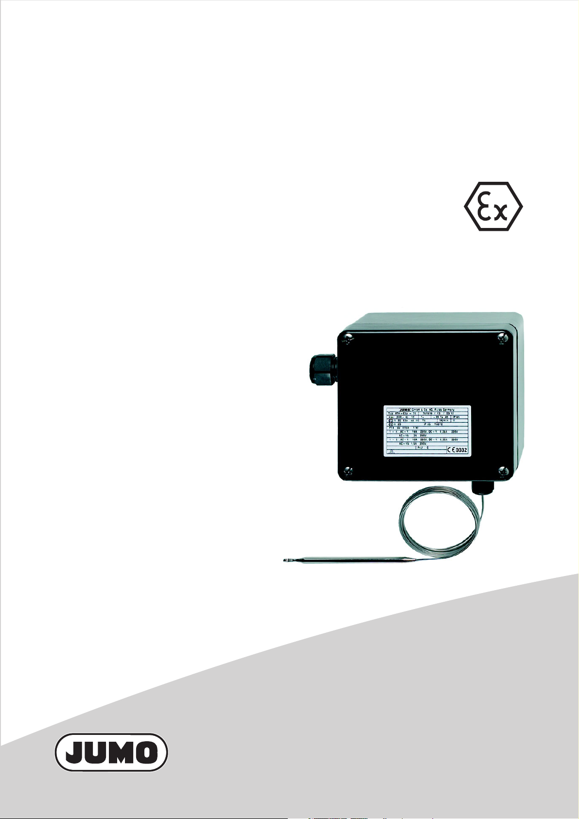
ATH-EXx
Explosion-protected surface-mounted thermostat
for potentially explosive gas atmosphere Zone 1 and
potentially explosive dust atmosphere Zone 21
B 605051.0
Operating Instructions
2011-04-01/00379556
Page 2

Please read these Operating Instructions before commissioning the instrument.
Keep the manual in a place that is accessible to all users at all times. Please
assist us to improve these operating instructions, where necessary. Your suggestions will be appreciated.
Phone+49 661 6003-0
Fax +49 661 6003-607
All necessary settings and, where appropriate, alterations inside the instrument
are described in these operating instructions. If any difficulties should still arise
during commissioning, you are asked not to carry out any unauthorized manipulations on the unit. You could endanger your rights under the instrument warranty! Please contact the nearest subsidiary or the head office in such a case.
Page 3

Contents
Seite
1 Introduction ............................................................................... 5
1.1 Typographical conventions ...................................................................... 5
1.1.1 Warning signs .............................................................................................. 5
1.1.2 Note signs ................................................................................................... 5
1.2 Application ................................................................................................. 6
1.3 Ex marking ................................................................................................. 6
1.4 Safety notes ............................................................................................... 6
2 Instrument identification .......................................................... 7
2.1 Nameplate .................................................................................................. 7
2.2 Type designation ....................................................................................... 8
3 Mounting .................................................................................... 9
3.1 Dimensions ................................................................................................ 9
3.2 Opening the surface-mounting thermostat .......................................... 10
3.3 Fixing the surface-mounting thermostat .............................................. 10
3.4 Capillary / temperature probe / pocket ................................................. 10
3.4.1 General ...................................................................................................... 10
3.4.2 Approved probes and sheaths .................................................................. 10
3.5 Permissible operating conditions at the pocket .................................. 11
3.5.1 Probe mountings 20 and 22 ...................................................................... 11
3.5.2 Probe mountings 10, 15, 21, 60, 65 .......................................................... 14
3.6 Mounting the probe ................................................................................. 14
4 Installation ............................................................................... 15
4.1 Regulations and notes ............................................................................ 15
4.2 Electrical connection .............................................................................. 16
4.3 Connection diagrams ............................................................................. 16
5 Settings .................................................................................... 17
5.1 Limit setting ............................................................................................. 17
5.1.1 TW, STW, TB (code 7) ............................................................................... 17
5.1.2 STB (code 70) ........................................................................................... 17
5.1.3 TB, STB (code 7-F or 70-F) ....................................................................... 18
5.2 Resetting the TB or STB limiter ............................................................. 19
5.3 Self-monitoring (fail-safe) ....................................................................... 19
5.3.1 Response to a fracture of the measuring system ..................................... 19
5.3.2 Response to low temperature ................................................................... 19
6 Instrument description ........................................................... 20
6.1 Technical data ......................................................................................... 20
7 Appendix .................................................................................. 24
Page 4

Page 5
1.1 Typographical conventions
1.1.1 Warning signs
Danger
This symbol is used when there may be danger to personnel if the instructions are ignored or not followed correctly!
Caution
This symbol is used when there may be damage to equipment if the instruc-
tions are ignored or not followed correctly!
1.1.2 Note signs
Note
This symbol is used when your special attention is drawn to a remark.
1 Introduction
Reference
This symbol refers to further information in other chapters or sections.
1
abc
✱ Action
Footnote
Footnotes are remarks that refer to specific points in the text. Footnotes
consist of two parts:
A marker in the text, and the footnote text.
The markers in the text are arranged as continuous superscript numbers.
The footnote text (in smaller typeface) is placed at the bottom of the page and
starts with a superscript number.
This symbol indicates that an action to be performed is described.
The individual steps are marked by this asterisk, e.g.
✱ Select setpoint
5
Page 6
1 Introduction
1.2 Application
Depending on the version, the explosion-protected surface-mounting
thermostat type ATH-EXx can be used as a
■ TW temperature monitor
■ TB temperature limiter
■ STW fail-safe temperature monitor
■ STB break-proof protection temperature limiter
in areas with an explosion hazard caused by gases, vapors or mists, Zone 1 or
in areas with combustible dust or dust/air mixtures, Zone 21.
If this surface-mounting thermostat is used inside the hazardous area, the
relevant regulations for mounting and operating equipment in such an area
must be observed.
Cutting through or kinking the capillary of the surface-mounting thermostat,
type ATH-EXx, will result in permanent failure of the instrument!
Only use the ATH-EXx with TZ 679 in areas that are classified as areas with
low mechanical risk.
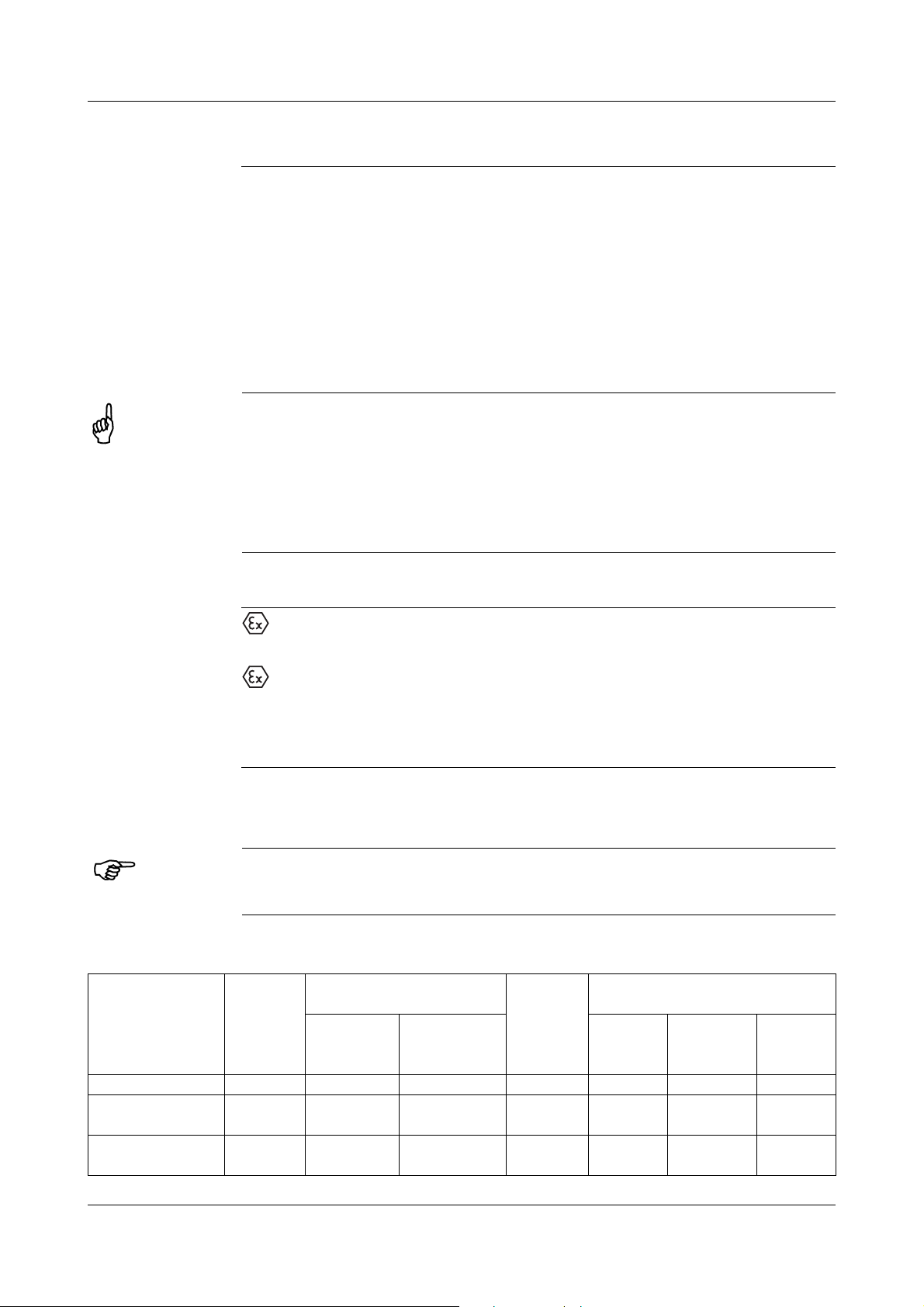
1.3 Ex marking
II 2G Ex ed IIC T5 bzw. T6
for potentially explosive gas atmospheres
II 2D Ex tD A21 IP65 T95°C bzw.T80°C
for potentially explosive dust atmospheres
Test certificate: PTB 03 ATEX 1187
CE marking and No. of notified body: CE 0044.
1.4 Safety notes
Filling liquid may escape in the event of a measuring system fracture. At present there is
no restrictive statement from the health authorities concerning any danger to health over
short periods and at low concentration, e.g. after a fracture of the measuring system.
Physical and toxicological properties of the substances that may escape in the
event of a system fracture.
End of scale°CDanger-
ous
reaction
< +200°C – +355°C 0,6 - 8 V X X X –
+200°C
+350°C
> 350°C
+500°C
– +490°C - - X X X –
– – – ––––
Ignition
Fire and
explosion hazard
Explosion
temp.
°C
% v/v
limit
Water
conta-
mination
Toxicological data
irritant danger to
health
– = no; X = yes
toxic
6
Page 7
2.1 Nameplate
( 4 )
( 3 )
( 2 )
( 1 )
( 5 )
( 6 )
( 8 )
( 9 )
(10)
(11)
( 7 )
( 12 )
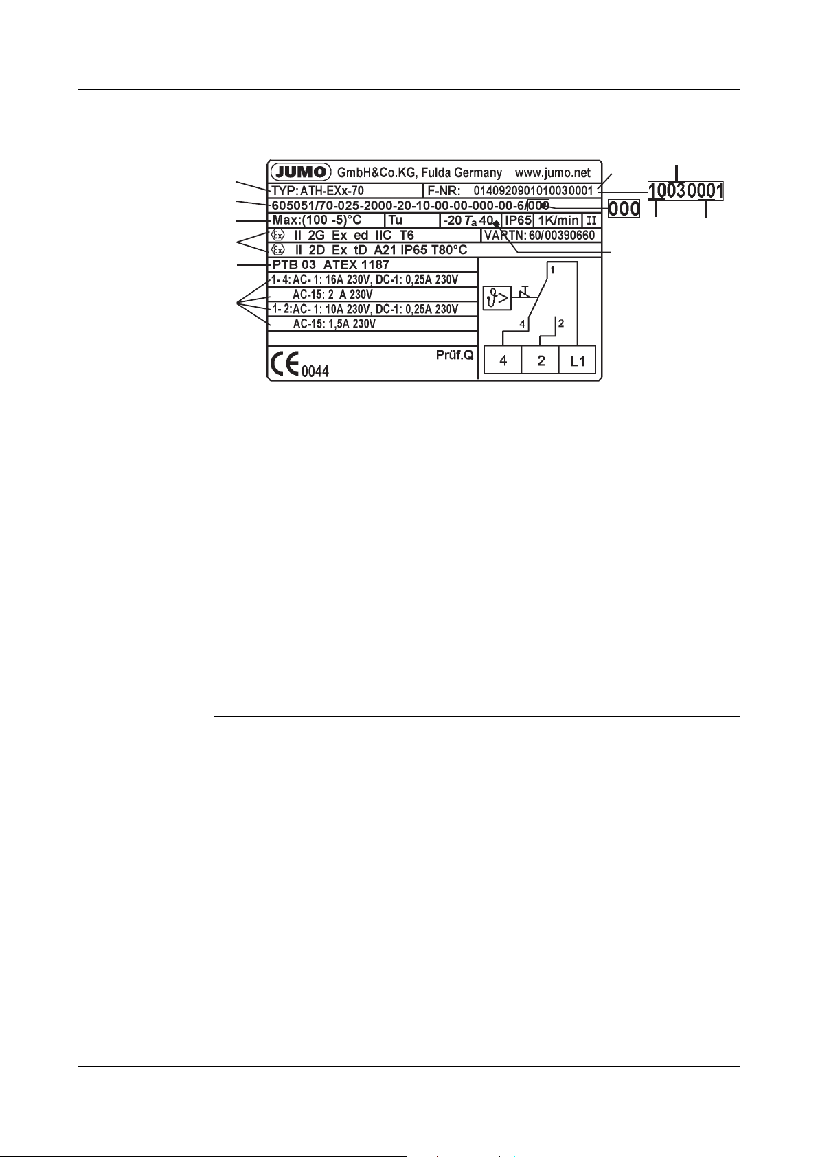
( 1 ) Type ➩ Chapter 2.2 "Type designation", page 8
( 2 ) Type code
( 3 ) Control range or limit value range / ambient temperature at which this
( 4 ) Ex-protection marking
( 5 ) Testing laboratory / certification
2 Instrument identification
thermostat was calibrated (option)
( 6 ) Switching capacity
( 7 ) Permissible ambient temperature
( 8 ) Serial number
( 9 ) Year of production
(10) Week of production
(11) Running serial device number
(12) Extra code
7
Page 8

2 Instrument identification
2.2 Type designation
ATH-EXx- . .- .
ATH Surface-mounting thermostat (with capillary)
ATH-EXx Marking for explosion-protected version
ATH-EXx- ..-. Code number for the function:
2=0Temperature monitor (TW)
with changeover contact.
Limit adjustable within the housing.
7=0Temperature limiter (TB)
with changeover contact and restart lock-out.
Limit adjustable within the housing.
7-F =0Temperature limiter (TB)
with changeover contact and restart lock-out.
Limit is factory-set.
20 =0Fail-safe temperature monitor (STW)
with changeover contact.
Limit adjustable within the housing.
70 =0Break-proof protection temperature limiter (STB)
with change-over contact and restart inhibit.
The limit value can be set by the installing engineer–
before commissioning the plant – within the housing.
70-F =0Break-proof protection temperature limiter (STB)
with change-over contact and restart inhibit.
Limit value set to a fixed value at the factory.
ATH-EXx- . .- .F=0Designation for factory-set limit setting.
Extra code (TZ) 679: Min. operating temperature: -50°C
8
Page 9
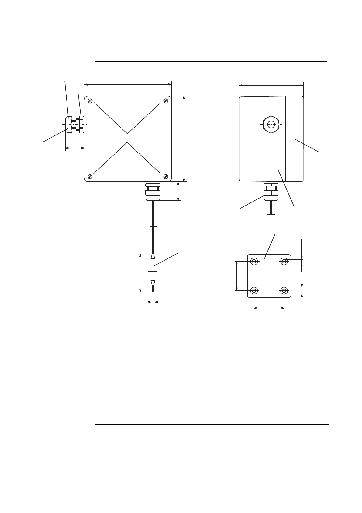
3.1 Dimensions
90
d
122
120
82
6.4
10.4
106
L
29
25
( 1 )
( 2 )
( 1.1 )
( 1.2 )
( 7 )
( 5 )
( 6 )
( 4 )
( 3 )
3 Mounting
(1) Ex cable gland M 20 x 1.5 x 6-12
(1.1) Screw-in thread Tightening torque: 3,75 Nm
(1.2) Compression screw Tightening torque: for cable dia. 06mm=3.5Nm
(2) Cover screws
(3) Cover
(4) Housing base
(5) Drilling diagram
(6) Ex cable gland for sealing the capillary exit
(7) Temperature probe
Tightening torque: for cable dia. 12 mm = 2.5 Nm
9
Page 10
3 Mounting
3.2 Opening the surface-mounting thermostat
✱ Unscrew the 4 cover screws (2)
✱ Remove cover (3) with seal (not visible)
Make sure that the seal is seated correctly when reassembling!
3.3 Fixing the surface-mounting thermostat
Mounting
position
To DIN 16257, NL 0 — NL 90 (other NL on request)
✱ Drill fixing holes according to the drilling diagram.
✱ Use the 4 screws to secure the housing base.
3.4 Capillary / temperature probe / pocket
3.4.1 General
Cutting through or kinking the capillary of the surface-mounting thermostat will
lead to permanent instrument failure!
Minimum permissible bending radius of the capillary is 5 mm.
The temperature probe must be mounted in a JUMO pocket, otherwise the
approval of the surface-mounting thermostat becomes invalid.
The temperature probe must completely immersed in the medium to be
measured.
To ensure their overall accuracy, the thermostats must only be used together
with the pockets supplied by the factory (diameter D = 8, 10 or 15 mm).
Pockets with a diameter D = 10 mm must only be fitted with probes with
diameter d = 8 mm.
Fitting several probes into a common pocket is only permitted with 2 or 3
probes (mounting type "10", diameter d = 6 mm) and 15 x 0.75 mm pockets.
When fitting 2 probes in a common pocket, the factory-supplied spring clip
must be fitted in the pocket.
For operation in air, probe mounting type "10" (without pocket) must be chosen.
3.4.2 Approved probes and sheaths
see current data sheet 606710
10
Page 11

3 Mounting
3.5 Permissible operating conditions at the pocket
3.5.1 Probe mountings 20 and 22
The values given below refer to the maximum loading on the probe mounting
concerned. The maximum pressure which can be sealed depends on the
mounting conditions and may possibly be lower.
3.5.1.1 Steel pockets
Materials Tube: St 35.8 I
Weld-in nipple: 16 Mo 3 (no turned groove)
Loading
Temperature Tube diameter
8 x 0.75 mm or
conical
max. permissible
pressure
100°C 89 bar 72 bar 48 bar
150°C 83 bar 67 bar 45 bar
200°C 78 bar 63 bar 42 bar
300°C 59 bar 47 bar 32 bar
400°C 46 bar 37 bar 25 bar
450°C 24 bar 19 bar 13 bar
With operating temperatures above 420°C, the permissible operating time is
limited to 200,000 hours. TRD 508 must be observed in this respect.
10 x 0.75 mm 15 x 0.75 mm
max. permissi-
ble pressure
max. permissi-
ble pressure
11
Page 12

3 Mounting
Permissible
incident flow
velocity
Temperature: +200°C
Thermal medium:
Tube diameter D:
Permissible incident flow velocity “v” at the maximum permissible
pressure loading and different immersion tube lengths “S”
air (1)
water, oil (2)
08mm
10 mm
15 mm
Permissible incident flow velocity “v” at the maximum permissible
pressure loading and different immersion tube temperatures “t”
12
Page 13

3.5.1.2 Stainless steel pocket
Materials Tube: X 6 CrNiMoTi 17122
Screw-in/weld-in nipple: X 6 CrNiMoTi 17122
Loading
Temperature Tube diameter
3 Mounting
100°C 92 bar 74 bar 50 bar
150°C 88 bar 71 bar 48 bar
200°C 83 bar 67 bar 45 bar
300°C 72 bar 58 bar 39 bar
400°C 67 bar 54 bar 36 bar
Permissible
incident flow
velocity
3.5.1.3 Brass pocket
Material CuZn (nickel-plated)
Loading
on request
Temperature Tube diameter
8 x 0.75 mm or
conical
max. permissible
pressure
10 x 0.75 mm 15 x 0.75 mm
max. permissi-
ble pressure
max. permissi-
ble pressure
Permissible
incident flow
velocity
100°C 50 bar 40 bar 27 bar
150°C 48 bar 39 bar 26 bar
on request
8 x 0.75 mm 10 x 0.75 mm 15 x 0.75 mm
max. permissible
pressure
max. permissi-
ble pressure
max. permissi-
ble pressure
13
Page 14

3 Mounting
( 1 )
( 2 )
3.5.2 Probe mountings 10, 15, 21, 60, 65
Materials Choice of steel, stainless steel or brass
Loading Only for use in unpressurized media.
Probe mounting 15 60, 65 10, 21
Maximum temperature +55°C +200°C
*
depending on the control range
3.6 Mounting the probe
The temperature probe (2) must be immersed in the medium for its entire
length, otherwise there will be appreciable deviations from the switching point.
In the case of probe mountings 20, 21 and 23, the temperature probe is
secured in the pocket by a clamping clip (1).
*
+500°C
*
14
Page 15

4.1 Regulations and notes
In case of electrical connections in a potentially explosive area, it is necessary
to comply with the relevant specifications.
■ The electrical connection must only be carried out by qualified personnel.
■ The choice of cable, the installation and the electrical connection must
conform to the requirements of VDE 0100 “Regulations on the Installation
of Power Circuits with Nominal Voltages below 1000 V” or the appropriate
local regulations.
■ If contact with live parts is possible while working on the instrument, it must
be completely disconnected from the electrical supply.
■ Earth the instrument at the PE terminal to the protective earth conductor.
This cable must have at least the same cross-section as used for the supply
cables. Earthing cables must be wired in a star configuration to a common
earth point that is connected to the protective earth conductor of the
electrical supply. Do not loop earthing cables, i.e. do not run them from one
instrument to another.
4 Installation
■ Apart from faulty installation, incorrect settings on the thermostat can also
affect the proper functioning of the subsequent process or lead to damage.
Setting up must therefore be restricted to qualified personnel. Please
observe the relevant safety regulations for such matters.
15
Page 16

4 Installation
2
4L12
4
1
PE N
12
4
42
L1
N
N
PE
PE
*
1
42
142
(2)
NPE
1
4
2
4L12
4.2 Electrical connection
✱ Open the housing.
➩ "Opening the surface-mounting thermostat", page 9
✱ Pass the connection cable (cable diameter 6 to 12 mm) through the Ex
cable compression gland (1).
➩ "Dimensions", page 8
✱ Make the connection to the terminals (2) in accordance with the connection
diagram.
✱ Fitting type X (no special tools).
✱ The connecting cable must have a fixed installation
✱ Connect the protective earth conductor to the PE terminal.
✱ Position the connecting cable in the housing and tighten the Ex cable com-
pression gland (1), using the tightening torque given below:
➩ "Dimensions", page 8.
Screw-in thread (1.1) into housing = 3.75 Nm
Compression screw (1.2). = 3.50 Nm for 06 mm cable diameter
Compression screw (1.2). = 2.50 Nm for 12 mm cable diameter
Ensure that connection line for operating temperatures up to -50°C
are low-temperature resistant.
4.3 Connection diagrams
TW / STW
TB / STB
16
Page 17

5.1 Limit setting
05
05
°C
( 1 )
5.1.1 TW, STW, TB (code 7)
✱ Open the housing.
➩ "Opening the surface-mounting thermostat", page 9
✱ Set the limit on the setpoint spindle (1).
5 Settings
5.1.2 STB (code 70)
Setting the limit
according to
the scale
Important note for setup and operation!
When the thermostat is used as a safety device for explosion protection in
accordance with EU Directive 94/9/EC Annex II Sec. 1.5, a functional test is
required that conforms to the applicable regulations.
The switching point must be fixed by the installation engineer after thermally
testing individual items, and secured against alteration. Several aspects
must be observed:
- the probe geometry and thermal coupling
- the maximum ambient temperature
- the maximum product temperature
✱ Open the housing.
➩ "Opening the surface-mounting thermostat", page 9
✱ Set the limit on the setpoint spindle (1) against the internal scale.
✱ Secure this setting by sealing the setpoint spindle ( 1 ), for instance with
“red” thread sealing wax, temperature resistant to at least +80°C)
17
Page 18

5 Settings
(A)
(1)
(1)
(2)
Setting the limits according to
specific system
characteristic
✱ Open the housing. ➩ "Opening the surface-mounting thermostat", page 9
✱ Warm up the temperature probe – in the system – to the intended limit
temperature (allow at least 5 minutes for the temperature to equalize), while
using a calibrated reference measuring device to measure and observe the
precise temperature at the temperature probe.
✱ Determine the required switching position (circuit 1-4 opens and circuit 1-2
closes) by rotating the setpoint spindle ( 1 ) from the end of the scale in the
direction of the start of the scale.
✱ Secure this setting by sealing the setpoint spindle ( 1 ), for instance with
“red” thread sealing wax, temperature resistant to at least +80°C.
A = secure the limit setting by sealing the setpoint spindle
with “red” thread sealing wax.
( 2 ) reset arm
5.1.3 TB, STB (code 7-F or 70-F)
Important note for setup and operation!
When the thermostat is used as a safety device for explosion protection in
accordance with EU Directive 94/9/EC Annex II Sec. 1.5, a functional test is
required that conforms to the applicable regulations.
In addition, suitable measures (such as calculation, thermal testing of
individual items) must be used to document that the switching point set by the
manufacturer prevents the temperature exceeding the given limit. The specific
local and operating conditions must be taken into account, such as:
- the probe geometry and thermal coupling
- the maximum ambient temperature
- the maximum product temperature
- The limit setting is fixed at the factory.
- Alteration is not permitted.
18
Page 19

5.2 Resetting the TB or STB limiter
If the temperature at the probe goes above the limit that has been set, the
electrical circuit 1-4 is opened and remains mechanically locked out. When the
critical temperature has fallen to about 9-15% below the set limit, the TB or
STB can be reset manually.
✱ Open the housing.
➩ "Opening the surface-mounting thermostat", page 9
✱ Press the reset arm ( 2 ) in the direction of the arrow.
➩ "( 2 ) reset arm", page 18
5.3 Self-monitoring (fail-safe)
5.3.1 Response to a fracture of the measuring system
On the STW or STB, in the event of a fracture of the measuring system (leakage)
the circuit 1-4 will remain permanently open.
On the STB, the microswitch is also mechanically and permanently locked out.
5 Settings
5.3.2 Response to low temperature
If the probe temperature of approx. -30°C (-60°C for the TZ 679) of the STW
and STB is gone below, the power circuit is opened.
When the temperature rises above the minimum probe temperature, the STW
resets itself automatically. The STB requires a manual reset.
➩ "Resetting the TB or STB limiter", page 19
19
Page 20

6 Instrument description
6.1 Technical data
Ex
marking
Explosion
protection
Explosion
protection type
II 2G Ex ed IIC T5 bzw. T6
for potentially explosive gas atmospheres
II 2D Ex tD A21 IP65 T95°C bzw. T80°C
for potentially explosive dust atmospheres
II 2G Equipment group II, Category 2,
equipment for potentially explosive gas atmospheres
II 2D Equipment group II, Category 2,
equipment for potentially explosive dust atmospheres
Ex General requirements
European Standard EN 60079-0
e Increased safety
European Standard EN 60079-7
d Flameproof enclosure
European Standard EN 60079-1
IIC Gas group
T5 or T6 Temperature class
Te st
certificate
Application in combustible dusts
European Standard EN 61241-0
EN 61241-1
IP65 Protection to EN 60529-IP65
T95°C or T80°C max. permissible surface temperature
(application in combustible dusts)
PTB 03 ATEX 1187
20
Page 21

Permissible
ambient temperature in
operation
Permissible
probe temperature
6 Instrument description
Capillary
°C
max. +40 +40
+55 +55
min. -20 (-50 et TZ 679)
Max operating temperature of the cable screw-connection for the TZ 679:
70°C.
max. limit +15% (+550°C with limit > 450°C)
Thermostat head °C
T6 T5
Permissible storage
temperature
Connecting
cable
Switching differential
in % of control/
limit range
Contact rating
max. +50°C, min. -20°C
max. +50°C, min. -50°C et TZ 679
diameter 6 to 12 mm, conductor cross-section up to 2.5 mm
Thermostats with end of scale
350°C
Switching
action
TW 3 3-5 TW 5 5-9
STW 5 5-7 STW 6 6-11
TB / STB – – – – TB / STB – – – –
Terminals 1-4 (break) Terminals 1-2 (make)
AC1: 230 V +10%, 10 A AC1: 230 V +10%, 5 A
AC15: 230 V +10%, 2 A AC15: 230 V +10%, 0.8 A
Nominal
value
Possible
actual
value
TW, STW
DC1: 230 V +10%, 0.25 A
Thermostats with end of scale
350°C
Switching
action
Nominal
2
Possible
value
actual
value
Terminals 1-4 (break) Terminals 1-2 (make)
AC1: 230 V +10%, 16 A AC1: 230 V +10%, 10 A
AC15: 230 V +10%, 2 A AC15: 230 V +10%, 1.5 A
Fusing required see contact rating
TB, STB
DC1: 230 V +10%, 0.25 A
21
Page 22

6 Instrument description
Enclosure protection
Operating
medium
Time constant
t
0.632
Mode of operation
Operating position (NL)
EN 60 529 - IP 65
Water, oil, air, superheated steam
in water in oil in air / superheated
steam
45 s 60 s 120 s
according to EN 60 730-1
TW,TB: Type 2BL = automatic action with micro-disconnection in
operation, no auxiliary supply required.
STW: Type 2BKL = automatic action with micro-disconnection in
operation, fail-safe.
STB: Type 2BFKL = automatic action with micro-disconnection in
operation, fail-safe, reset only permissible by means of a tool.
To DIN 16257, NL 0 — NL 90 (other NL on request)
Weight approx. 1.2 kg
Capillary and
probe material
Min. bending
radius of the
capillary
End of scale Capillary Probe
up to +200°C copper, Mat. Ref. 2.0090
up to +300°C copper, Mat. Ref. 2.0090
up to +500°C stainless steel,
up to +300°C stainless steel,
5mm
electro-tinned
1.5 mm diameter
electro-tinned
1.5 mm diameter
Mat. Ref. 1.4571
1.5 mm diameter
Mat. Ref. 1.4571
1.5 mm diameter
copper, Mat. Ref. 2.0090
electro-tinned
brazed
stainless steel,
Mat. Ref. 1.4571
brazed
stainless steel,
Mat. Ref. 1.4571
welded
stainless steel,
Mat. Ref. 1.4571
welded
22
Page 23

6 Instrument description
Switching point
accuracy
Mean ambient
temperature
effect
in % of scale span, referred to the limit value at Ta +22°C.
in upper third of scale
TW, TB
at start of scale
in upper third of scale
STW, STB
at start of scale
in % of scale span, referred to the limit value.
A deviation of the ambient temperature at the thermostat head and/or the cap-
illary from the +22°C calibration ambient temperature produces a shift in the
switching point:
higher ambient temperature = lower switching point
lower ambient temperature = higher switching point
Surface-mounting thermostats with end of scale
< +200°C +200°C +350°C > 350°C
TW
TB
STW
STB
TW
TB
+0
-4
+0
-6
+0
-5
+0
-7
%
%
%
%
STW
STB
TW
TB
STW
STB
effect due to the thermostat head, % per °C
0.08%/K 0.17%/K 0.06%/K 0.13%/K 0.14%/K 0.12%/K
effect due to capillary, % per °C per meter
0.047%/K 0.054%/K 0.09%/K 0.11%/K 0.04%/K 0.03%/K
23
Page 24

7 Appendix
24
Page 25

7 Appendix
25
Page 26

7 Appendix
26
Page 27

7 Appendix
27
Page 28

7 Appendix
28
Page 29

7 Appendix
29
Page 30

7 Appendix
30
Page 31

Page 32

JUMO GmbH & Co. KG
Street address:
Moritz-Juchheim-Straße 1
36039 Fulda, Germany
Delivery address:
Mackenrodtstraße 14
36039 Fulda, Germany
Postal address:
36035 Fulda, Germany
Phone: +49 661 6003-0
Fax: +49 661 6003-607
e-mail: mail@jumo.net
Internet: www.jumo.net
JUMO Instrument Co. Ltd.
JUMO House
Temple Bank, Riverway
Harlow, Essex CM20 2TT, UK
Phone: +44 1279 635533
Fax: +44 1279 635262
e-mail: sales@jumo.co.uk
Internet: www.jumo.co.uk
JUMO Process Control, Inc.
8 Technology Boulevard
Canastota, NY 13032, USA
Phone: 315-697-5866
1-800-554-JUMO
Fax: 315-697-5867
e-mail:
Internet: www.jumo.us
info@jumo.us
 Loading...