

Page 1
Series ATH.-SE-..
Surface-mounting thermostats
B 603031.0
Operating Instructions
2013-04-15/00073788
Page 2

Please read these Operating Instructions before commissioning the instrument.
Keep the operating instructions in a place which is accessible to all users at all
times. Please assist us to improve these operating instructions. Your suggestions will be welcome.
Phone +49 661 6003-0
Fax +49 661 6003-607
All necessary settings and, where appropriate, alterations inside the instrument
are described in these operating instructions. If, however, any difficulties should
arise during commissioning, you are asked not to carry out any unauthorized
manipulations on the unit. You could endanger your rights under the instrument
warranty! Please contact the nearest subsidiary or the main factory in such a
case.
Page 3

Contents
Page
1 Introduction ............................................................................... 5
1.1 Typographical conventions ...................................................................... 5
1.1.1 Warning signs .............................................................................................. 5
1.1.2 Note signs ................................................................................................... 5
1.2 Application ................................................................................................. 6
1.3 Marking ...................................................................................................... 6
1.4 Safety notes ............................................................................................... 6
2 Instrument identification .......................................................... 7
2.1 Nameplate (example) ................................................................................ 7
2.2 Type designation ....................................................................................... 7
3 Mounting .................................................................................... 8
3.1 Dimensions ................................................................................................ 8
3.2 Opening the case .................................................................................... 10
3.3 Fixing the surface-mounting thermostat .............................................. 10
3.3.1 Code s (rigid stem) .................................................................................... 10
3.3.2 Code f (with capillary) ................................................................................ 10
3.4 Capillary / temperature probe / sheath ................................................. 11
3.4.1 General ...................................................................................................... 11
3.4.2 Approved process connections ................................................................ 11
3.5 Permissible pressure at the sheath ....................................................... 12
3.5.1 Sheaths 20 and 30 .................................................................................... 12
3.6 Mounting the probe ................................................................................. 13
4 Installation ............................................................................... 14
4.1 Regulations and notes ............................................................................ 14
4.2 Electrical connection .............................................................................. 15
4.2.1 Closing the case ....................................................................................... 16
Page 4

Contents
Page
5 Settings .................................................................................... 18
5.1 Setting the limit value ............................................................................. 18
5.2 Resetting the STB ................................................................................... 19
5.3 Self-monitoring ........................................................................................ 19
5.3.1 Behaviour in the event of a measuring system breakage ......................... 19
5.3.2 Response to low temperature ................................................................... 19
5.4 Using the STW(STB) as STB ................................................................... 19
6 Instrument description ........................................................... 20
6.1 Technical data ......................................................................................... 20
Page 5

1.1 Typographical conventions
1.1.1 Warning signs
1 Introduction
V
Danger
This symbol is used where there may be danger to personnel if the instructions are disregarded or not followed accurately.
Caution
A
1.1.2 Note signs
H
v
1
abc
This symbol is used where there may be damage to equipment if the instructions are disregarded or not followed accurately.
Note
This symbol is used to draw your special attention to a remark.
Reference
This symbol refers to additional information in other chapters or sections.
Footnote
Footnotes are comments which refer to specific parts of the text. Footnotes
consist of two parts:
1) The marking in the text, arranged as continuous superscript numbers.
2) The footnote text, at the bottom of the page and preceded by a superscript
number.
✱ Action
This symbol marks the description of a required action.
The individual steps are indicated by an asterisk, e.g.
✱ Select setpoint
5
Page 6

1 Introduction
1.2 Application
Surface-mounting thermostats Series ATH.-SE-.. are approved for monitoring
installations on steel-hulled ocean-going ships (e.g. steam and boiler plant,
indirect heating systems) as:
❏ Temperature monitor (TW)
❏ Safety temperature monitor STW (STB)
❏ Safety temperature limiter (STB).
The versions comply with DIN EN 14597 and are approved as per the guidelines of the Classification Societies:
- Germanischer Lloyd
- Det Norske Veritas
- Bureau Veritas
- Pressure Equipment Directive 97/23/EC CE0036
(ATH.-SE-20 and ATH.-SE-70 only)
Cutting through or kinking the capillary of the surface-mounting thermostats
A
Type ATH.-SE-.. will lead to permanent failure of the instrument!
1.3 Marking
H
Surface-mounting thermostats Type ATH.-SE-.. are approved as per DIN EN 607302-9.
1.4 Safety notes
In the event of a measuring system breakage, the filling liquid can escape.
H
There is currently no statement by the health authority concerning hazards to
health in the event of short-term exposure and low concentration, e.g. in the
event of a measuring system break.
Physical and toxicological properties of substances which may escape in the
event of a system break:
End of scale Dangerous
reaction
below +200 °C no +355 °C 0.6 - 8 yes yes yes no
+200 °C to +300 °C
6
no +490 °C - - yes yes yes no
Fire/explosion hazard Water
Ignition
temperature
°C
Explosion
limit
% v/v
contami-
nation
Toxicological data
irritant danger to
health
toxic
Page 7
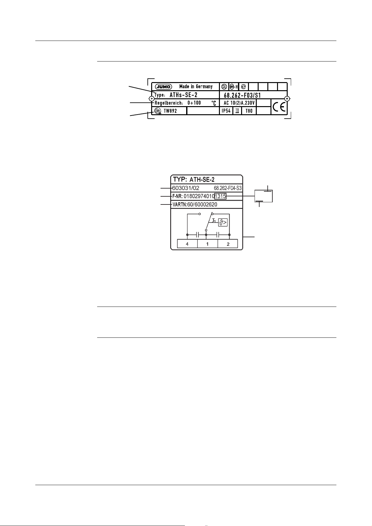
2.1 Nameplate (example)
( 1 )
( 2 )
( 3 )
( 4 )
( 6 )
( 2 )
( 1 )
( 5 )
( 7 )
1315
on the case bottom section:
(1) Type code (see type designation, below)
(2) Control range / contact rating
(3) Approval mark
on the thermostat case (inner section):
2 Instrument identification
( 1 ) Type
( 2 ) Type code
( 4 ) Fabrication number
( 5 ) Year of manufacture
( 6 ) Week of manufacture
( 7 ) Connection diagram
2.2 Type designation
Type code
Basic type
603031 ATH.-SE surface-mounted thermostat with microswitch
Basic type extension
02 ATH.-SE-2 Temperature monitor TW with changeover contact
20 ATH.-SE-20 Safety temperature monitor STW (STB),
70 ATH.-SE-70 Safety temperature limiter STB,
with changeover contact
with N/C contact
Design
1ATHs-SE-.. with rigid shaft
2ATHf-SE-.. with capillary
7
Page 8
3 Mounting
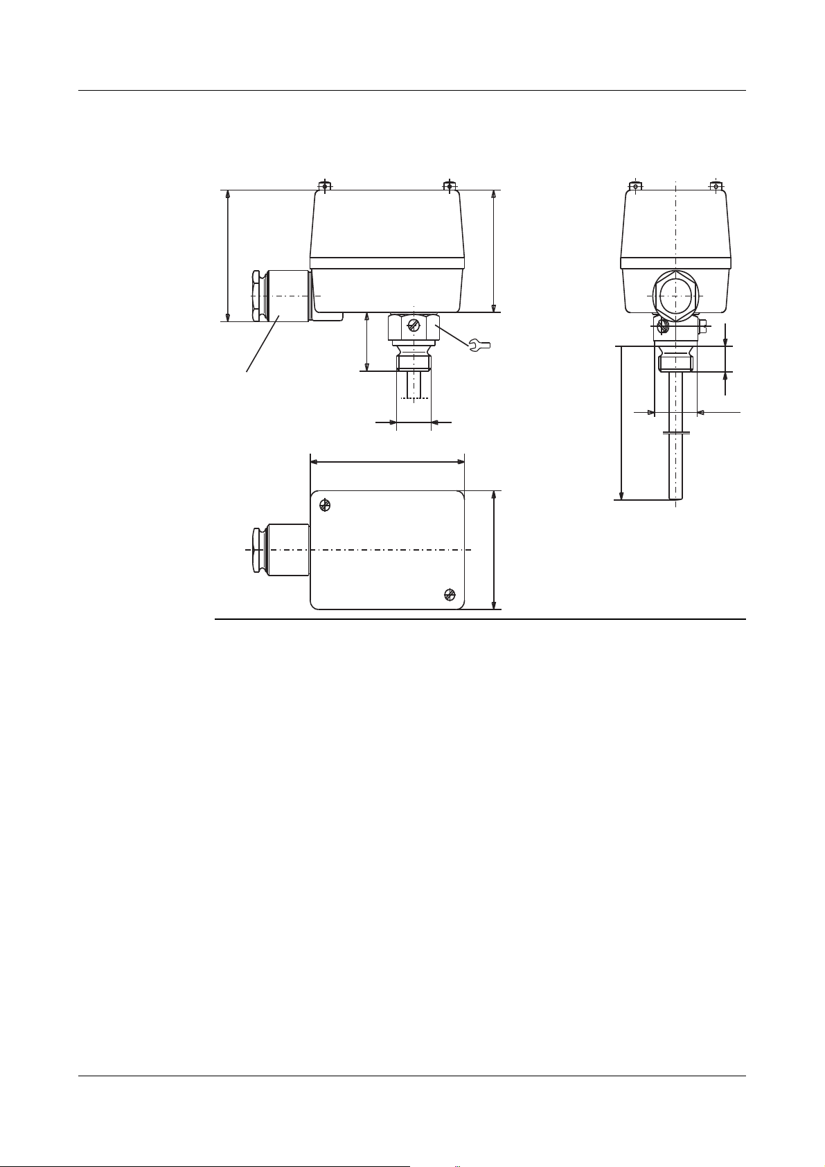
K M24x1,5
M 20x1,5
DIN 89280-Z14
27
70
66
G1/2
33
14
Ø 26
S = max. 200 (150)
67
94
3.1 Dimensions
ATHs-S E-2,
ATHs-SE-20
with
sheath "20"
(up to +150 °C)
8
Page 9

ATHs-SE-2 (20)
K M24x1,5
M 20x1,5
DIN 89280-Z14
70
66
G 1/2
Ø 26
S = max. 200 (150)
Ø 90
~85
14
27
Ø
K M24x1,5
M 20x1,5
DIN 89280-Z14
70
12
66
G1/2
14
G1/2
Ø 26
S = max. 200 (150)
33
67
94
24
27
Ø
with
sheath "30"
(up to +300 °C)
3 Mounting
ATHf-S E -70 ,
with
sheath "20"
(up to +300 °C)
9
Page 10

3 Mounting
( 1 )
( 5 )
( 5 )
3.2 Opening the case
Opening
V
✱ Unscrew the two lead-sealable cheese-head screws ( 5 )
✱ Remove the upper part of the case ( 1 )
Ensure that the gasket is seated correctly when reassembling!
3.3 Fixing the surface-mounting thermostat
Operating
position
3.3.1 Code s (rigid stem)
3.3.2 Code f (with capillary)
unrestricted
(for open-air mounting on request)
The case journal is secured in the enlarged open end of the sheath by two
fixing screws.
by ½" pipe thread on the case journal
10
Page 11

3.4 Capillary / temperature probe / sheath
3.4.1 General
Cutting through or kinking the capillary will lead to permanent failure of the
A
H
instrument!
Minimum permissible bending radius of the capillary is 5 mm.
The temperature probe must be fitted in a JUMO sheath, otherwise the
approval of the surface-mounting thermostat becomes invalid.
The temperature probe must be completely submerged in the medium.
In order to ensure the general accuracy of response, the instruments must only
be used with the sheaths supplied from the factory (diameter D = 8, 10 mm).
Only probes with a diameter d = 8 mm may be fitted in sheaths with a diameter
D = 10 mm.
When the operating medium is air, connection type "10" (without sheath) must
be selected.
3 Mounting
3.4.2 Approved process connections
Te mp er at ur e
probe
Sheaths 20, 30
H
10
refer todata sheet 606710 !
11
Page 12

3 Mounting
3.5 Permissible pressure at the sheath
3.5.1 Sheaths 20 and 30
The following values refer to the maximum pressure of the probe mounting
A
3.5.1.1 Stainless steel sheath
concerned. The maximum pressure which can be sealed depends on the
mounting conditions and may possibly be lower.
Material
Permitted flow
velocities
3.5.1.2 Sheath "20" made of brass
l
Tube and nipple material: X 6 CrNiMoTl 17 122
Temperature Tube diameter
100°C 92bar 74bar
150°C 88bar 71bar
200°C 83bar 67bar
300°C 72bar 58bar
on request
Temperature Tube diameter
8 x 0.75 mm or conical 10 x 0.75 mm
Max. permissible pressure Max. permissible pressure
Sheath "20" tube and nipple material: brass
8 x 0.75 mm 10 x 0.75 mm
Emitted flow
velocities
H
A
12
Max. permissible pressure Max. permissible pressure
100 °C 50 bar 40 bar
150 °C 48 bar 39 bar
on request
The plain cylindrical probe, Form 10 must only be used in pressureless
medium.
Due to the general accuracy of response, the instrument must only be used
with the factory-supplied sheaths.
Page 13

3.6 Mounting the probe
( 1 )
( 2 )
Submerge the sheath and the temperature probe (2) into the medium and
H
ensure that the temperature probe (2) is completely submerged in the medium
because otherwise, greater switching point deviations will occur.
For thermostats with longdistance line (abbreviation
"f"), the temperature probe
is fastened in the sheath by
means of the clamping
piece (1) for connection
types "20".
3 Mounting
13
Page 14

4.1 Regulations and notes
4 Installation
V
❏ The electrical connection must only be made by qualified personnel.
❏ The choice of cable, the installation and the electrical connection must
conform to the requirements of VDE 0100 “Regulations for the installation
of power circuits with nominal voltages below 1000 V”, or the appropriate
local regulations.
❏ If contact with live parts is possible while working on the unit, it must be
completely disconnected from the supply.
❏ Earth the instrument at the PE terminal to the protective conductor. This
cable must have a cross-section that is at least as large as the supply
cables. Earth cables must be run in a star configuration to a common earth
point which is connected to the protective earth of the supply. Do not loop
earth cables, i.e. do not run them from one instrument to another.
❏ Apart from faulty installation, incorrect settings on the thermostat can affect
the proper functioning of the following process or lead to damage. Setting
up must therefore be restricted to qualified personnel. Please observe the
appropriate safety regulations in this respect.
14
Page 15

4.2 Electrical connection
( 4 )
( 5 )
✱ Open the case.
➈ Section 3.2 “Opening the case”, page 10.
✱ Pass the connection cable (cable diameter 10 — 16,5 mm) through the
screw connection (3). Fitting type"X" (no special tools), screw connection
up to 2.5 mm
✱ Remove the protective cover ( 4 ).
✱ Establish the connection to the terminals ( 1 ) in accordance with the appro-
priate connection diagram.
✱ Connect the protective conductor to terminal PE ( 2 ).
✱ Refit the protective cover ( 4 ) and snap it onto the guide lug ( 5 ).
2
conductor cross-section.
4 Installation
15
Page 16

4 Installation
H
( 1 )
( 2 )
( 3 )
( 4 )
( 5 )
( 5 )
Connection
diagrams
TW / STW (STB) STB as N/C contact
4.2.1 Closing the case
✱ Make sure that the plastic gasket in the lower part of the case ( 2 ) is seated
correctly.
On thermostats with code -70, the external reset button ( 3 ) must be located
H
precisely on top of the internal reset button ( 4 ) for the microswitch, since this
is the only way the reset button ( 3 ) can be operated from the outside.
✱ Place the upper part of the case ( 1 ) onto the lower part ( 2 ).
with signal contact
STB
with (N/C) break contact
16
✱ Tighten the lead-sealable cheese-head screws ( 5 ).
Page 17

4 Installation
Cable relief ✱ Turn the screw connection ( 1 ) clockwise until the cable inlet is sealed and
the cable is secured against pulling out. The cable has to be protected
against vibration overload by leaving sufficient extra cable length ( 2 ).
✱ Close the case.
17
Page 18

5 Settings
(1) Top stop
( 2 ) Bottom stop
( 3 ) Set point indicator
( 4 ) Scale division
( 5 ) Set point setter
5.1 Setting the limit value
✱ Open the case.
➈ Section 3.2 “Opening the case”, page 10.
✱ Set the limit value on the set point setter ( 5 ) using a screwdriver.
18
Page 19

5.2 Resetting the STB
After the temperature has fallen below the set limit value (safe temperature
limit) by about 10% of the scale range, the microswitch can be reset.
Action
1. 2. 3.
5 Settings
✱ Unscrew the cap nut
(1).
✱ Press the reset but-
ton (2) until the micro
switch is reset.
✱ Screw the cap nut (1)
back on
5.3 Self-monitoring
5.3.1 Behaviour in the event of a measuring system breakage
On the STB and STW (STB), the circuit stays open permanently in the event of
H
5.3.2 Response to low temperature
H
a measuring system breakage (leakage).
On the STB, the microswitch is additionally locked.
If the probe temperature goes below the minimum value of -10 °C, the circuit is
opened.
After the minimum probe temperature is exceeded, the STB must be manually
reset.
➈ Section 5.2 “Resetting the STB”, page 19.
The TW and STW reset automatically.
5.4 Using the STW(STB) as STB
V
The restart lock as per DIN EN 14597 must be ensured by the subsequent circuit. This circuit must be in accordance with VDE 0116.
19
Page 20

6 Instrument description
6.1 Technical data
Permissible
ambient
temperature
in operation
maximum +80 °C +80 °C
minimum
Capillary Thermostat head with scale limit value
-40 °C -40 °C below +200°C
-20 °C -20 °C >
200 °C to < 350 °C
Permissible
overtemperature safety
Permissible
storage
temperature
Case Cover: aluminium die casting with screws for lead sealing
Connection
cable
Switching
differential
in % of
limit value
range
on the probe during use
max. scale end value +15%
maximum +50 °C, minimum -50 °C
Base: die-cast aluminium, painted
Diameter 10 — 16.5 mm, maximum conductor cross-section 2.5 mm
Code
nominal value possible actual value
S 1
S 2
S 3
only on types 2 and 20
3
6
1.5
2
3-4
6-8
1-2
Max.contact
rating
230 V, 10 (2) A AC, p.f. = 1 (0.6) 230 V, 0.25 A DC
Fusing required see contact rating
Protection IP54 as per EN 60 529, operation under normal conditions
Operating
medium
Time constants
t
0.632
Water, oil, air, superheated steam
in water in oil in air / superheated steam
<
45 sec. < 60 sec. < 120 sec.
TW, STW (STB) with hysteresis 3% and 6%
TW, STW (STB) with hysteresis 1.5%
230 V, 6 (1.2) A AC, p.f. = 1 (0.6)
20
Page 21

6 Instrument description
+0
-5
%
+0
-10
%
Operating
mode
as per EN 60 730-1
TW: Type 2BL = automatic mode
STB, STW (STB): Type 2BK = automatic mode
Operating position
unrestricted (with open-air mounting on request)
Weight approx. 0.65 kg
Capillary and
probe materials
End of scale Capillary Probe
up to +200 °C copper Mat. Ref. 2.0090
up to +300 °C copper Mat. Ref. 2.0090
up to +500 °C stainless steel,
with microswitch disconnection in operation,
which requires no auxiliary energy source.
with microswitch disconnection in operation,
with fail-safe facility.
tin-plated, 1.5 mm dia.
tin-plated, 1.5 mm dia.
1.5 mm dia.
copper Mat. Ref. 2.0090
tin-plated, brazed
stainless steel
Mat. Ref. 1.4571, brazed
stainless steel
Mat. Ref. 1.4571, welded
Minimum
bending radius
Switching point
accuracy
Mean ambient
temperature
influence
5mm
(in % of scale range;
in relation to the set point or limit value at +22 °C ambient temperature)
TW in upper third of scale
at start of scale
± 1.5%
± 1.5%
STB, STW (STB) in upper third of scale
at start of scale
(in % of scale range) in relation to the limit value
There is a displacement of the switching point if the ambient temperature at
the thermostat head and/or the capillary deviates from the +22 °C calibration
ambient temperature.
higher ambient temperature = lower switching point
lower ambient temperature = higher switching point
for temperatures with end of scale:
below +200 °C +200 °C to +350 °C
TW STB/STW (STB) TW STB/STW (STB)
influence on thermostat head, % per °C
0.08 0.17 0.06 0.13
influence on capillary, % per °C per m length
0.047 0.054 0.09 0.11
21
Page 22

Page 23

Page 24

JUMO GmbH & Co. KG JUMO Instrument Co. Ltd. JUMO Process Control, Inc.
Street address:
Moritz-Juchheim-Straße 1
36039 Fulda, Germany
Delivery address:
Mackenrodtstraße 14
36039 Fulda, Germany
Postal address:
36035 Fulda, Germany
Phone: +49 661 6003-0
Fax: +49 661 6003-607
E-mail: mail@jumo.net
Internet: www.jumo.net
JUMO House
Temple Bank, Riverway
Harlow - Essex CM20 2DY, UK
Phone: +44 1279 63 55 33
Fax: +44 1279 63 52 62
E-mail: sales@jumo.co.uk
Internet: www.jumo.co.uk
6733 Myers Road
East Syracuse, NY 13057, USA
Phone: 315-437-5866
1-800-554-5866
Fax: 315-437-5860
E-mail: info.us@jumo.net
Internet: www.jumousa.com
 Loading...