

Page 1
EM type series
Panel-mounting thermostats
B 602026.0
Operating instructions
2013-03-20/00073776
Page 2

Please read this operating manual before starting up the device. Keep the operating manual in a place accessible to all users at all times. Please help us to
improve these instructions where necessary. Your comments are highly appreciated.
Phone +49(0)6 61 - 60 03-7 16
Fax +49(0)6 61 - 60 03-5 04
All necessary settings and required work inside the device are described in this
operating manual. If any difficulties should still arise dur-ing start-up, you are
asked not to carry out any unauthorized manipulations on the unit. You could
endanger your rights under the device warranty! Please contact the nearest
subsidiary or the head office.
Page 3

Inhalt
1 Introduction .................................................................................. 4
1.1 Typographical conventions ......................................................................... 4
1.1.1 Warning signs ................................................................................................. 4
1.1.2 Indicative signs ............................................................................................... 4
1.2 Application .................................................................................................... 5
1.3 Identification ................................................................................................. 5
1.4 Safety information ........................................................................................ 6
2 Identifying the device .................................................................. 7
2.1 Type plate (example) .................................................................................... 7
2.2 Type designation .......................................................................................... 7
3 Installation .................................................................................... 8
3.1 Dimensions ................................................................................................... 8
3.2 Fastening the panel-mounting thermostat ................................................ 9
3.2.1 Fasting the switching head ............................................................................ 9
3.3 Capillary
3.3.1 General information ...................................................................................... 10
3.3.2 Approved process connections ................................................................... 11
3.3.3 Sheath made of steel 22, 23, 32, 41, 42 and 45 .......................................... 11
3.3.4 Sheath made of stainless steel 20, 22, 40 and 41 ....................................... 13
3.3.5 Sheath made of brass 20 and 40 ................................................................. 13
3.3.6 Probe connections 50, 52 and 54 ................................................................ 13
/ temperature probe / sheath ................................................... 10
4 Installation .................................................................................. 15
4.1 Standards and information ........................................................................ 15
4.2 Electrical connection ................................................................................. 15
4.3 Wiring diagrams ......................................................................................... 16
5 Settings ....................................................................................... 17
5.1 Unlocking the safety temperature limiter (STB) ...................................... 17
5.2 Limit value setting ...................................................................................... 18
5.3 Self-monitoring of the STB and STW (STB) ............................................. 18
5.4 Use of the STW (STB) as STB .................................................................... 18
6 Device Description .................................................................... 19
6.1 Technical data ............................................................................................. 19
Page 4

1 Introduction
1.1 Typographical conventions
1.1.1 Warning signs
Danger
V
A
1.1.2 Indicative signs
H
This symbol is used when there may be danger to personnel if the instructions are ignored or not followed correctly!
Caution
This symbol is used where there may be damage to equipment if the instructions are disregarded or not followed accurately!
Note
This symbol is used to draw your special attention to a remark.
Reference
v
1
abc
✱ Handling instructions
This symbol refers to additional information in other chapters or sections.
Footnote
Footnotes are comments that refer to specific parts of the text. Footnotes
consist of two parts:
A marker in the text and the foot note text itself.
The markers in the text are arranged as continuous superscript numbers.
The footnote text is located at the end of the page, in a typeface 2 degrees
smaller than the main text, and is preceded by a superscript number.
This symbol indicates that an action to be performed is described.
The individual steps are indicated by asterisks, for example:
✱ Opening the case
4
Page 5

1.2 Application
DGRL
Thermostats are used to control and monitor thermal processes.
Panel-mounting thermostats operate according to the fluid or gas expansion
principle. The electrical switching element is a micro switch.
The devices of the EM type series are available as safety -temperature monitors
STW and safety temperature limiters STB.
In the event of a malfunction, the STB switches the monitored machine line to
an operational safe status.
Versions as per: DIN EN 14597
STW (STB) Safety temperature monitor
STB Safety temperature limiter
Design test as per:
-DIN EN 14597
- Directive governing pressure systems 97/23/EC
- DVGW Gas equipment directive 90/396/EEC (only type EM-80)
1 Introduction
The declaration of conformity can be found in the internet under:
www.jumo.net ➯ Products ➯ Thermostats ➯ Data sheet 602026
or is available on request.
Bending/kinking or cutting the probe line of the panel-mounting thermostats of
A
the EM type series will lead to a permanent device failure!
1.3 Identification
Depending on the device version:
(for detailed information, see type plate imprint)
5
Page 6

1 Introduction
1.4 Safety information
Filling fluid can emerge in the event of a measuring system break. A hazard to
H
health is excluded as per the present information.
Physical and toxic features of the expansion means, which could emerge in
the event of a measuring system break:
Control range
with
scale limit value
°C
< +200 no +355 0.6 - 8 Yes Yes
ⱖ +200 ≤ +350 no +490 - - Yes Yes
> +350 ≤ +500 no no no no no no no
Hazardous
reaction
1
There is currently no statement by the health authority concerning hazards to
health in the event of short-term exposure and low concentration, e.g. in the
event of a measuring system break.
temperature
Fire and
explosion hazard
Ignition
°C
Explosion
limit
Vol .%
hazardous
to waters
Information about toxicology
irritant
hazardous to
health
1
1
toxic
no
no
6
Page 7
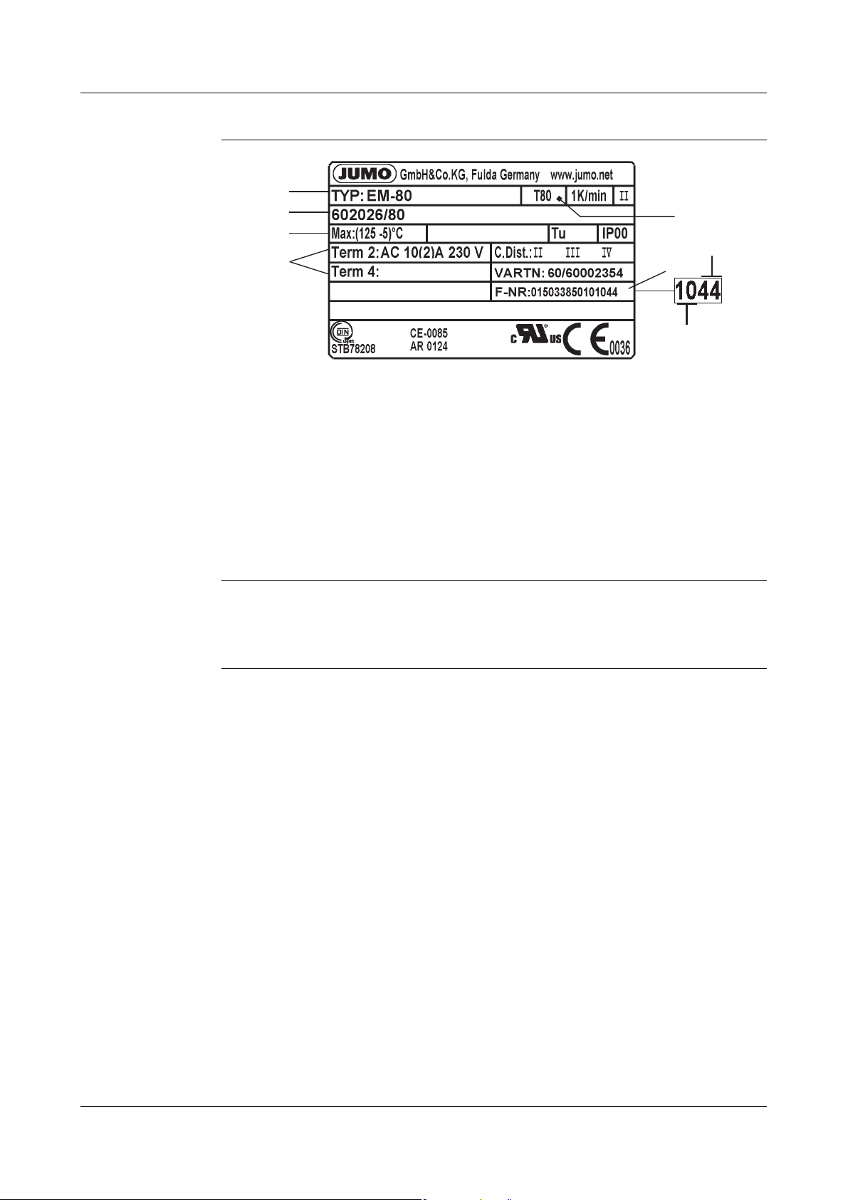
2.1 Type plate (example)
( 5 )
( 3 )
( 7 )
( 8 )
( 4 )
( 2 )
( 1 )
( 6 )
( 1 ) Type
( 2 ) Type code
( 3 ) Control- and limit value range / ambient temperature at which this
thermostat was calibrated (option)
( 4 ) Contact rating
( 5 ) Permissible ambient temperature
( 6 ) Serial number
2 Identifying the device
( 7 ) Week of manufacture
( 8 ) Year of manufacture
2.2 Type designation
Type
designation
EM - .. - .. - .. / .. Panel-mounting thermostat with single-pole
- 20 - E Safety temperature monitor STW (STB) with
- 30 - E Safety temperature monitor STW (STB) with
- 80 Safety temperature limiter STB with N/C con-
micro switch, connection "10" as standard
(plain cylindrical probe)
change-over contact, limit value adjustable
change-over contact, limit value permanently
factory-set
tact and restart lock, limit value permanently
factory-set
/ 707 Temperature compensation on the switching
head
/ 702 Snap switch contacts, gold plated
/ 574 Micro switch with N/C contact,
restart lock and additional signal contact (STB
only)
7
Page 8
3 Installation
2
1
SW10
46
12
15.5
36.5
L
16
6
21
26
29
52
SW13
Ød
Ø 1.5
2
1
6
G
21
16
21
36.5
1.5
L
46
52
2.5
29
Ø
d
Ø
B
38
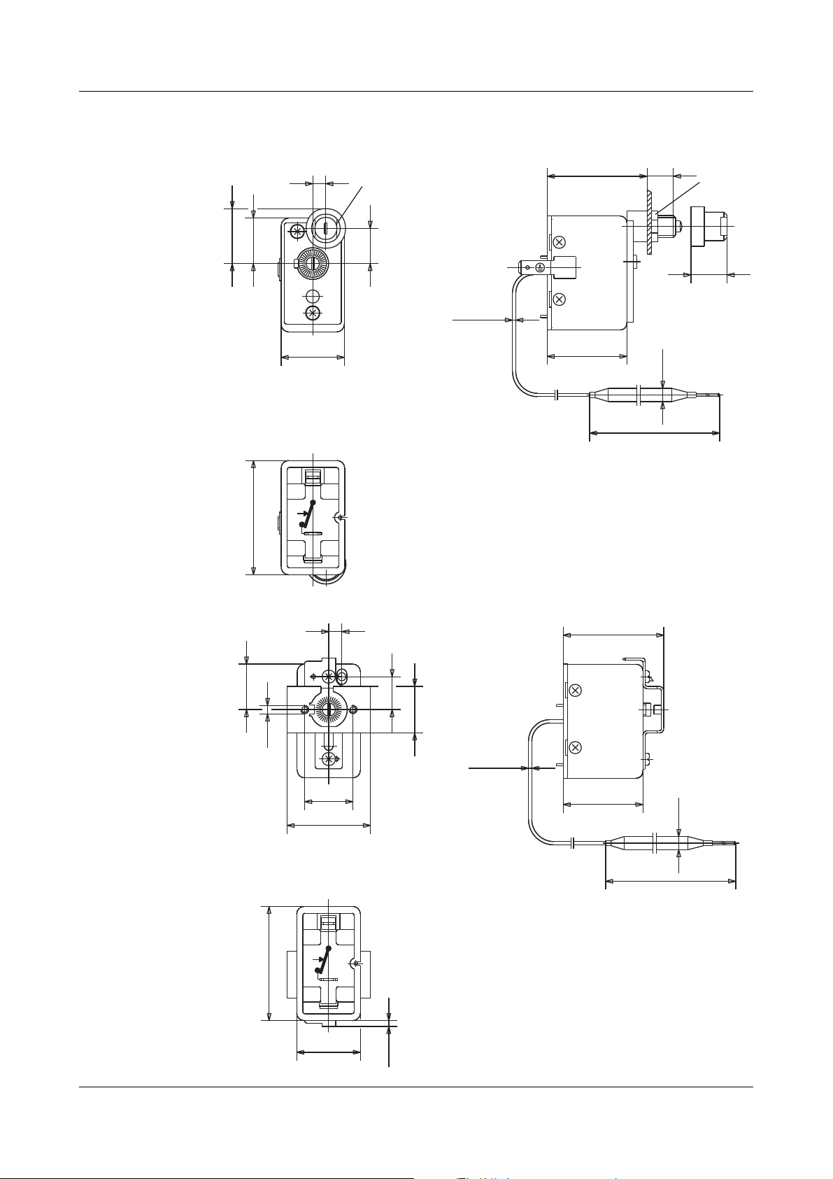
3.1 Dimensions
EM-80
with central
fastening
(as standard)
EM-20-E
EM-30-E
EM-80
with
fastening bridge
704, 705, 706
8
Page 9

3.2 Fastening the panel-mounting thermostat
( 1 )
( 2 )
( 3 )
( 4 )
( 1 )
( 1 )
( 2 )
3 Installation
Operating position
any
3.2.1 Fasting the switching head
Type E M-80
with central
fastening
Central fastening
( 1 ) Cap nut M10 x 1 (width
across flats 10)
( 2 ) Fastening nut M10 x 1
(width across flats 13)
( 3 ) Panel
( 4 ) Restart knob
Type Dimension
(mm)
XY
EM-80 16 6
Type EM-20-E,
EM-30-E,
EM-80
with
fastening bridge
With two M3 screws
(M4, for extra code 704)
on the chassis:
(1) Screw
(2) Panel
Type Dimension
(mm)
XY
EM-20-E,
EM-30-E
EM-80 15 6
Extra code
(all types)
706 (as standard) 3.5 22
704 4.5 28
705 3.5 33
- - - -
Dimension
BG
(mm)
9
Page 10

3 Installation
(B)
(C)
3.3 Capillary / temperature probe / sheath
3.3.1 General information
Bending/kinking or cutting the capillary of the panel-mounting thermostats will
A
lead to a permanent device failure!
The minimum admissible bending radius of the capillary is 5 mm.
The temperature probe must be installed in JUMO sheaths, otherwise, the
approval of the panel-mounting thermostats will become null and void.
Ensure that the temperature probe is completely submerged in the medium to
be measured. Ensure that the temperature probe or the sheath does not make
contact with the container or pipe walls.
Only use the devices in combination with the factory-supplied sheaths (d = 8
mm or d = 10 mm) to ensure the general response accuracy.
The d = 10 mm sheaths must only be used for d = 8 mm probes.
One sheath (15 x 0.75 mm) can be used for 2 or 3 cylindrical probes with a
diameter of d = 6 mm.
When using a sheath for 2 probes, fit the factory-supplied contact pressure
spring into the sheath.
For the operating medium air, select the connection type "10“ (without sheath).
For sheaths 22, 41, 42 and 45 made of material St35.8 I, the admissible service life is limited to 200,000 operating hours at operating temperatures
exceeding +420 °C. Adhere to the TRD 508 for applications
in this range.
10
( B ) Temperature probe
( C ) Immersion tube
Page 11

3.3.2 Approved process connections
3 Installation
Te mp er a tu re
probe
Screwconnections
Sheaths 20, 21, 22, 23, 24, 40, 41, 42
H
10
50, 52, 54, 60, 65
refer to data sheet 606710 !
3.3.3 Sheath made of steel 22, 23, 32, 41, 42 and 45
Material
Tube Screw-in nipples Welding nipples
St 35.8 I Steel 1.0038 Steel 1.5415
Capacity
Temperature Pipe diameter
8 x 0.75 mm or
conical
Maximum admissible pressure
100 °C 89 bar 72 bar 48 bar
150 °C 83 bar 67 bar 45 bar
200 °C 78 bar 63 bar 42 bar
300 °C 59 bar 47 bar 32 bar
350 °C 50 bar 40 bar 27 bar
10 x 0.75 mm 15 x 0.75 mm
max. admissible
operating
temperature
Tube Nipple max. admissible operating temperature*
static load without load
St 35.8 I Screw-in nipples +300 °C
Welding nipples +450 °C
* observe the max. admissible probe temperature of the respective thermostat version.
For operating temperatures > +420 °C: observe the operating life of 200,000 h at a static
load TRD508. Sheath "21" (UO) and "31" (UZO): Use only in pressureless medium.
+530 °C
11
Page 12

3 Installation
permissible
flow
rates
Material: St35.8 I
Temperature: +200 °C
Heat transfer oil:
Pipe diameter Ø:
Permissible flow rate [m/s] at maximum admissible pressure load and different
immersion tube length "S“
Air ( 1 )
water, oil ( 2 )
. . . . . . . . . . . . . .
Immersion tube length
08mm
10 mm
15 mm
( 1 ) Air
( 2 ) Water, oil
[mm]
Permissible flow rate [m/s] at maximum admissible pressure load and different
immersion tube temperature.
Material: St35.8 I
Immersion tube length "s":
Heat transfer oil:
Pipe diameter Ø:
200 mm
Air ( 1 )
water, oil ( 2 )
. . . . . . . . . . . . . .
08mm
10 mm
15 mm
12
Temperature
( 1 ) Air
( 2 ) Water, oil
[°C]
Page 13

3.3.4 Sheath made of stainless steel 20, 22, 40 and 41
Capacity
Material of pipe and nipple: Stainless steel (1.4571)
Pipe diameter Ø
3 Installation
Te mp er at ur e
100°C 92bar 74bar 50bar
150°C 88bar 71bar 48bar
200°C 83bar 67bar 45bar
300°C 72bar 58bar 39bar
400°C 67bar 54bar 36bar
8 x 0.75 mm
or conical
3.3.5 Sheath made of brass 20 and 40
Capacity
Material of pipe and nipple: CuZn, nickel plated
Te mp er at ur e
100°C 50bar 40bar 27bar
8 x 0.75 mm 10 x 0.75 mm 15 x 0.75 mm
10 x 0.75 mm 15 x 0.75 mm
Maximum admissible pressure
Pipe diameter Ø
Maximum admissible pressure
150°C 48bar 39bar 26bar
3.3.6 Probe connections 50, 52 and 54
(probe making directly contact with the medium)
Material of nipple CuZn Steel (1.0038) Stainless steel (1.4571)
Temperature °C 200 300 400
Probe material Ø
Cu-DHP
St35 1.4571
mm
4
5
6
7
8
9
10
Device function
STB, STW (STB)
2 bar
13
Page 14

3 Installation
(1)
(2)
Design 10, 15, 21, 60, 65:
A
H
only use in pressureless medium.
Ensure that the temperature probe (2) is completely submerged in the medium
because otherwise, greater switching point deviations will occur.
For connection types 20, 21 and 22, the temperature probe is fixed in the
sheath with the clamping piece ( 1 ).
14
Page 15

4.1 Standards and information
■ Only allow electricians to carry out the electrical connection.
■ The choice of cable, the installation and the electrical connection of the
device must conform to the requirements of VDE 0100 "Regulations on the
Installation of Power Circuits with Nominal Voltages below 1000 V" and/or
the appropriate local regulations.
■ If contact with live parts is possible while working on the device, it must be
completely isolated from the supply.
■ Earth the device at the PE terminal to the protective earth conductor.
Ensure that this line has at least a cross section identical to that of the supply lines. Earth/ground cables must be routed in a star configuration to a
common earthing point that is connected to the protective earth of the supply installation. Do not loop earth cables, i.e. do not run them from one
device to another.
■ In addition to a faulty installation, also incorrectly set values on the thermostat could impair the orderly function of the following process or lead to
other damage. Restrict the setting to expert personnel. Please adhere to
the safety regulations for this case.
4 Installation
4.2 Electrical connection
■ Terminals and connections are suitable for internal wires
■ The connection is suitable for stationary line
■ Line insertion without strain relief
■ The device corresponds to protection class I.
Capillary tube without protective earth function!
For the probe and the capillary line, the user is
responsible for the required protection against electrical shock.
15
Page 16

4 Installation
( 1 )
2
Plug-in connector
(as standard)
Screwconnection
(extra code 699)
( 1 ) = Tab connector DIN 46 244-A 6.3 x 0.8
( 1 ) Plug-in sleeve 6.3 with connection screw suitable for wires up to 2.5
2
; fitting type "699", without auxiliary means
mm
( 2 ) Terminal strip
4.3 Wiring diagrams
EM-20-E
EM-30-E
16
EM-80 EM-80/574
Page 17

5.1 Unlocking the safety temperature limiter (STB)
5 Settings
EM-80,
with fastening
bridge
704, 705, 706
Once the set limit value is gone below (dangerous temperature) by approx.
10% of the scale range, the micro switch can be unlocked.
EM-80
with central fastening as standard
✱ Actuate the restart knob using a small screwdriver.
✱ Unscrew the cap
✱ Press the restart knob
✱ Screw on the cap again
17
Page 18

5 Settings
°C
(1)
(2)
(3)
5.2 Limit value setting
EM-20-E ( 1 ) Set point value setter
( 2 ) Scale subdivision
( 3 ) Set point value indicator
✱ Adjust the set point value setter via the inter-
nal scale using a screwdriver
EM-30-E
EM-80
The limit value is permanently factory set and sealed. Readjustment is not
admissible.
5.3 Self-monitoring of the STB and STW (STB)
If the measuring system is destroyed, i.e. if the expansion fluid emerges, the
H
pressure in the diaphragm drops and permanently opens the current circuit.
Unlocking is no longer possible.
If the probe has cooled down to a temperature below approx. -20 °C, the current circuit is also opened, however, automatically closes again, when the temperature rises above -10 °C.
5.4 Use of the STW (STB) as STB
V
The restart lock required as per DIN EN 14597 must be ensured by the following switching diagram. This switching diagram must comply with VDE 0116.
18
Page 19

6.1 Technical data
Permissible
ambient temperature
STW (STB)
max. see nameplate
Capillary Switch head
STW (STB)
STW (STB)
STB
STB
STB
extra code
707
6 Device Description
STW (STB)
STB
extra code
707
with scale limit
value /
limit value
min. -20 °C
Permissible
probe
temperature
Permissible
storage
temperature
Case Sheet steel, galvanized
Switching element
max.: Scale limit value / limit value +15%,
(with scale limit value between +90 °C and 120 °C = min. 25 K
min. -35 °C
max. +50 °C, min. -50 °C
Ty pe D es c ri pt i on
EM-20-E, EM-30-E
EM-
80 with N/C contact
EM-
80/574 as N/C contact with additional signal contact
-40 °C
-20 °C
-40 °C
1 1-pin snap switch
with change-over contact
+18 °C 0 °C
< 200 °C
≥
200 °C ≤ 350 °C
>
350 °C ≤ 500 °C
19
Page 20

6 Device Description
maximum
contact rating
Ty pe
EM-
20-E
EM-
30-E
EM-
80
EM-80/574
Contact reliability:
To ensure high switching reliability, we recommend a minimum load of:
- AC/DC 24 V, 100 mA with silver contacts (standard)
- AC/DC 10 V, 5 mA with gold-plated contacts (extra code "702")
Rating surge voltage:
2500 V (via the switching contacts 400 V)
Over-voltage category II
Required fuse rating:
see maximum switching current
Current
Terminal 2 Terminal 4
10(2) A 2(0.4) A
0.25 A 0.25 A DC 230 V +10%
10(2) A
0.25 A DC 230 V +10%
0.1 A
(extra code "702")
10(2) A 2(0.4) A
0.25 A 0.25 A DC 230 V +10%
- -
Voltage
AC 230 V +10%
cos ϕ = 1 (0.6)
AC 230 V +10%
cos ϕ = 1 (0.6)
AC / DC 24 V
AC 230 V +10%
cos ϕ = 1 (0.6)
Switching point
accuracy
(in % from the scale range; referring to the set point or limit value
at T
+22 °C, with increasing temperature)
U
Hysteresis in % Switching point accuracy in %
Typ e
EM-30-E,
EM-80
20-E
EM-
fluid-filled gas-filled
7
- 710
7
- -
in the upper third
of the scale or limit
value
+0 / -8
+0 / -8
at the scale begin-
ning
- -
+ 0 / - 10
20
Page 21

Protection class EN 60 529 - IP 00
Degree of soiling 2
6 Device Description
Operating
medium
Time constant
t
0.632
Function as per EN 60 730-1 and DIN EN 60 730-2-9 and DIN EN 14597
Rated position any
Weight approx. 0.2 kg
Material
of capillary and
probe
Water, oil, air, hot steam
in water in oil in air / hot steam
≤ 45 s ≤ 60 s ≤ 120 s
STW(STB): 2 BKLNP
STB 2 BFHKLNPV
Scale limit value Capillary Sensors
up to +200 °C Copper mat.No.: Cu-DHP
Ø 1.5 mm
Copper, mat.No.: Cu-DHP
hard soldered
minimum
bending radius
of the capillaries
up to +350 °C Copper mat.No.: Cu-DHP
Ø 1.5 mm
up to +500 °C Stainless steel,
Ø 1.5 mm
against surcharge
up to +350 °C Stainless steel,
Ø 1.5 mm
5mm
Stainless steel, mat.No.:
1.4571
hard soldered
Stainless steel, mat.No.:
1.4571
welded
Stainless steel, mat.No.:
1.4571
welded
21
Page 22

6 Device Description
Average
ambient temperature
influence
(in % from the scale range) referring to the limit value.
When the ambient temperature on the switch head and / or the capillary deviates from the calibration ambient temperature +22 °C, a switching point offset
occurs.
Higher ambient temperature = lower switching point
Lower ambient temperature = higher switching point
For temperatures with scale limit value / limit value:
< +200 °C ≥ +200 °C ≤ +350 °C ≥ +400 °C ≤ +500 °C
STW (STB)
Hysteresis in %
77 10
Ambient temperature influence on the switch head in %/K
0.43 0.35 0.24
Ambient temperature influence on the capillary in %/m
0.09 · K · m 0.07 · K · m 0.05 · K · m
STB
Ambient temperature influence on the switch head:
0.35 K/K
Te mp er a tu re
compensation
"707"
Ambient temperature influence on the capillary in K/m
0.07 K/K·m
For detailed information, please refer to the graphical presentation in data
sheet 602026
22
Page 23

Page 24

JUMO GmbH & Co. KG JUMO Instrument Co. Ltd. JUMO Process Control, Inc.
Street address:
Moritz-Juchheim-Straße 1
36039 Fulda, Germany
Delivery address:
Mackenrodtstraße 14
36039 Fulda, Germany
Postal address:
36035 Fulda, Germany
Phone: +49 661 6003-0
Fax: +49 661 6003-607
E-mail: mail@jumo.net
Internet: www.jumo.net
JUMO House
Temple Bank, Riverway
Harlow - Essex CM20 2DY, UK
Phone: +44 1279 63 55 33
Fax: +44 1279 63 52 62
E-mail: sales@jumo.co.uk
Internet: www.jumo.co.uk
6733 Myers Road
East Syracuse, NY 13057, USA
Phone: 315-437-5866
1-800-554-5866
Fax: 315-437-5860
E-mail: info.us@jumo.net
Internet: www.jumousa.com
 Loading...