

Page 1

SC-923
INSTRUCTION MANUAL
1
Page 2

CONTENTS
I. SPECIFICATIONS ........................................................................................ 1
II. SET-UP
1. Installing to the table ............................................................................................................................1
2. Connecting the cords ...........................................................................................................................4
3. Attaching the connecting rod .............................................................................................................12
4. Setting procedure of the machine head ............................................................................................ 13
5. Adjusting the machine head...............................................................................................................14
........................................................................................................ 1
III. FOR THE OPERATOR ............................................................................. 15
1. Operating procedure of the sewing machine ...................................................................................15
2. Operation panel (CP-18) .....................................................................................................................16
3. Operating procedure of the sewing pattern ......................................................................................17
(1) Reverse feed stitching pattern
(2) Overlapped stitching pattern ............................................................................................................ 18
4. One-touch setting
5. Production support function .............................................................................................................. 21
6. Setting of functions of SC-923 ........................................................................................................... 24
7. Function setting list ............................................................................................................................26
8. Detailed explanation of selection of functions ................................................................................. 32
9. Automatic compensation of neutral point of the pedal sensor ......................................................47
10. Selection of the pedal specications ................................................................................................47
11. Stitch alignment for the reverse stitching at the end of sewing (for heavy-weight materials) ....48
12. Input/output function of the hand switch and knee switch ............................................................. 49
13. Use of the hand switch and the knee switch .................................................................................... 50
14. Selecting procedure of the key-lock function ..................................................................................51
15. Initialization of the setting data ..........................................................................................................51
16. External input / output connector ...................................................................................................... 52
17. How to connect the material edge sensor ........................................................................................53
................................................................................................................................19
......................................................................................................... 17
IV. MAINTENANCE ....................................................................................... 54
1. Removing the rear cover ....................................................................................................................54
2. Replacing the fuse ..............................................................................................................................54
(1) PWR PCB
(1) CTL PCB ..........................................................................................................................................55
3. Error codes
........................................................................................................................................ 54
..........................................................................................................................................56
i
Page 3

I. SPECIFICATIONS
Supply voltage Single phase 100 to 120V 3-phase 200 to 240V Single phase 220 to 240V
Frequency 50Hz/60Hz 50Hz/60Hz 50Hz/60Hz
Operating environment
Input 600VA 600VA 600VA
* The electric power is a reference value for the model equipped with the LU-2810ES-7 machine head.
It differs by the selected machine head.
Temperature : 5 to 35˚C
Humidity : 35 to 85%
Temperature : 5 to 35˚C
Humidity : 35 to 85%
Temperature : 5 to 35˚C
Humidity : 35 to 85%
II. SET-UP
The SC-923 can be used with the direct-motor type machine head as a stand-alone control box.
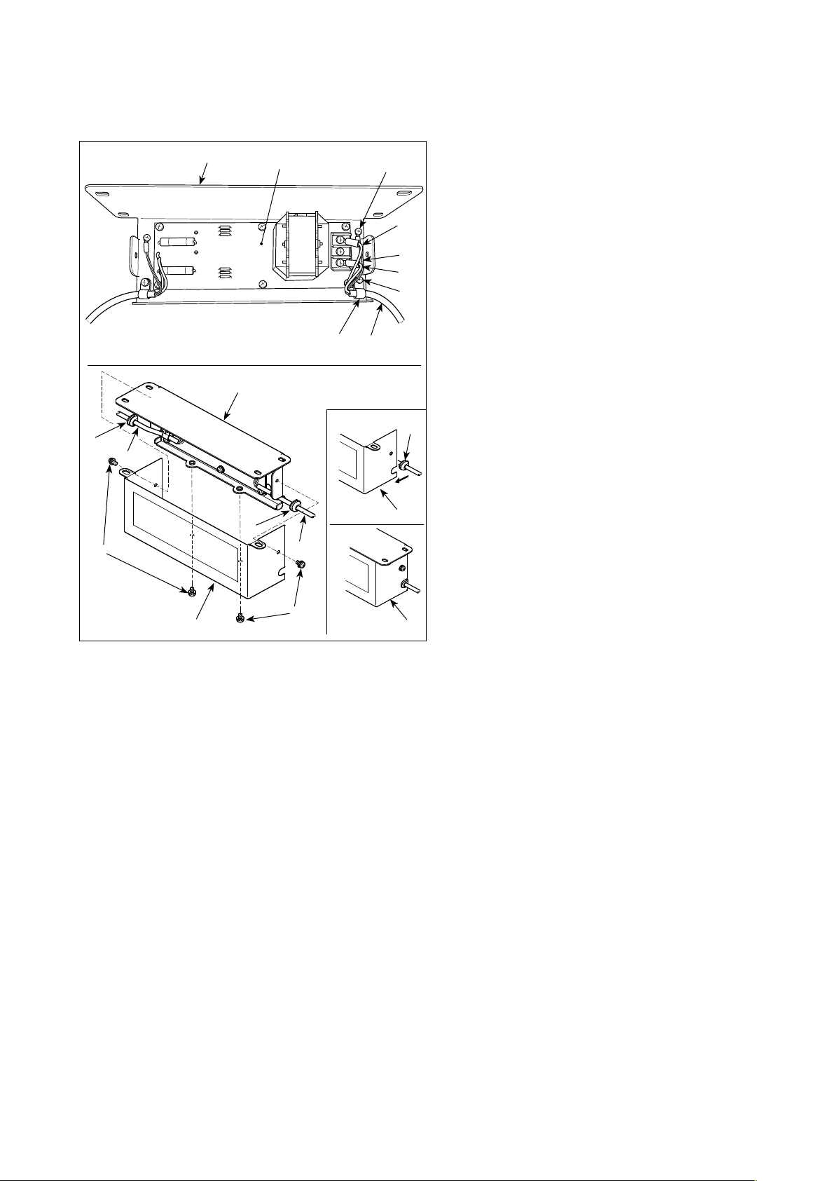
1. Installing to the table
To use the SC-923 with the direct-motor type machine head, install the control box on the table according to
the following instruction.
This describes the procedure for installing the SC-
923 on the table of the LU-2810ES-7 sewing ma-
❶
❷
❸
❹
❶
❾
❻
❺
❼
❽
chine. To use any other machine head, install the
control box on the table referring to the Instruction
Manual for the main body of the relevant sewing ma-
chine. Install the control box suspending plate on the
table with mounting bolts supplied with the unit. At
this time, insert the nuts and washers supplied with
the unit as accessories as shown in the gure so that
the motor unit can be securely xed on the table.
1) Press three bolts
cessories into the motor hanging bolt hole in the
table and x them.
2) Fix suspending plate
the three bolts with plain washer ❷, spring wash-
er ❸ and nut ❹.
3) Fix rubber
washer ❼ and nut ❽.
4) Hang one end of the control box on the threaded
part of rubber on the side which has two bolts.
Then, hang the other end of the control box on
the opposite side.
5) Temporarily x the other threaded part of rubber
with plain washer ❾ and nut . In this case, the
spring washer is not used.
6) Adjusting the installing position of the control box.
Then, securely tighten the nuts.
on the suspending plate with spring
❻
supplied with the unit as ac-
❶
supplied with the unit on
❺
– 1 –
Page 4
< How to install the reactor box >
* For the EU-type models, install the reactor
box that is supplied with the sewing machine.
❽
❾
❼
❸
❸
❽
❷
❶
❺
❶
❹
A
❻
1) Connect the terminals of power cord ❶ of the
SC-923 to reactor-box PCB asm. ❷ and to
reactor box mounting plate ❸.
Connect brown wire A to the rst connector and
blue wire B to the third connector respectively
from the top of terminal block on the reactor box
C
B
PCB asm. using screws. Connect green/yellow
wire C to reactor box mounting plate ❸ with
earth setscrew ❹.
2) Attach cable clip ❺ to the power cord of SC-923.
Attach the power cord together with the cable
clip to reactor box mounting plate ❸ with cable
clip setscrew ❻.
3) Attach cord bushes ❽ to input/output cables ❶
and ❼ of the reactor box. Attach both bushes in
❽
the same manner.
4) Attach reactor box cover to reactor box
mounting plate ❸ with four reactor-box cover
setscrews ❾.
At this time, x cord bushes ❽ attached to input/
output cables ❶ and ❼ in the concave section
on reactor box cover to eliminate a gap between reactor box and cover .
❾
– 2 –
Page 5

< How to install the reactor box to the table >
5 mm
Operator side
Oil pan
(Caution) The reactor box should be installed at the
SC-923
Pass the cable between the
table and the control box.
position at which the box is spaced 5 mm
away from the oil pan.
1) Connect the reactor box input cord to the power switch.
2) Connect SC-923 power cord to reactor box .
3) Secure the cords with staples .
4) Install reactor box
to the table at the location
as shown in the gure using four wood screws
supplied with the unit.
5) Fix input/output cables ❶ and ❼ of reactor
box on the table using cord staples sup-
plied with the unit. At this time, take care not
to allow the input/output cords to intersect with
each other.
– 3 –
Page 6

2. Connecting the cords
WARNING :
• To prevent personal injury caused by abrupt start of the sewing machine, carry out the work after
turning OFF the power switch and a lapse of 5 minutes or more.
• Topreventdamageofdevicecausedbymaloperationandwrongspecications,besuretoconnect
allthecorrespondingconnectorstothespeciedplaces.
• To prevent personal injury caused by maloperation, be sure to lock the connector with lock.
• As for the details of handling respective devices, read carefully the Instruction Manuals supplied
with the devices before handling the devices.
Following connectors are prepared on the SC-923. Connect the connectors coming from the machine head
to the corresponding places so as to t the devices mounted on the machine head.
❷ ❸❼
❶ ❹
CN30 Motor signal connector
❶
❺
❻ ❾
❽
❷ CN36 Machine head solenoid: Provided with solenoids for thread trimming, reverse feed stitching, one-
touch type reverse feed switch.
❸ CN37 Presser foot lifting solenoid (Only for the automatic presser foot lifter type)
❹ CN38 Operation panel: Various kinds of sewing can be programmed. (For details of the operation panel
other than CP-18, refer to the Instruction Manual for the panel to be used.)
❺ CN39 Standing machine pedal : JUKI standard PK70, etc. Sewing machine can be controlled with exter-
nal signals.
❻ CN44 Hand switch: Hand switch other than the touch-back switch.
❼ CN51 Extended input/output connector
❽ CN55 LED lamp (+5 V type): The LED lamp can be connected optionally. (Refer to "III-4. One-touch
setting" p.19 for how to adjust the quantity of light.)
❾ CN58 Extended input connector (for the sensor input, etc.)
CN59 Extended output connector (for the solenoid valve output)
– 4 –
Page 7

1) Pass cords
reverse feed solenoid through table hole A and
route them under the table.
of the thread trimmer solenoid,
❶
❼
A
B
❽ ❹ ❻
❸
❷
❶
❺
2) Loosen screw
open the cover.
3) Connect 14P cord
head to connector ❹ (CN36). Connect 2P con-
nector ❺ to connector ❻ (CN37).
Connect 9P connector
to connector ❽ (CN30) on the PCB.
in cover ❷ with a screwdriver to
B
coming from the machine
❸
coming from the motor
❼
❾
Insert 26P cord
sert 24P cord into connector (CN44). Insert
22P cord into connector (CN58).
– 5 –
into connector (CN59). In-
❾
Page 8

[Connecting the connector for the operation panel]
[Connection of the pedal of standing-work machine]
4) The connector for the operation panel is provided.
Paying attention to the orientation of the connec-
tor , connect it to connector (CN38) located
on the PCB. After connecting, securely lock the
connector.
(Caution) Be sure to turn OFF the power before
connecting the connector.
5) To use the pedal unit with the sewing machine
for standing work, insert PK70 connector into
connector (CN39: 12P) on the PCB.
(Caution) Be sure to turn OFF the power before
connecting the connector.
(Caution) Be sure to securely insert the respective connectors after checking the inserting directions
since all connectors have the inserting directions. (When using a type with lock, insert the con-
nectors until they go to the lock.) The sewing machine is not actuated unless the connectors are
inserted properly. In addition, not only the problem of error warning or the like occurs, but also
the sewing machine and the control box are damaged.
[How to bundle all cords]
6) After inserting the connector, put all cords togeth-
er with cable clip band located on the side of
the box.
(Caution) 1. Fix the cord clamp and the cable clip
band following the attaching proce-
dure.
2. When removing the connector, remove
it from the wire saddle and remove it
while pressing the hook of the cable
[Howtoxcableclipband]
Panel
clip band.
Pull
[How to remove cable clip band]
Panel
Push the hook.
Pushing the
hook portion,
push the band
to remove it.
Push
– 6 –
Page 9

B
❷
7) Close cover
and x the cover by tightening
❷
screw B with a screwdriver.
(Caution) Take care not to allow the cord to be
caught under cover ❷.
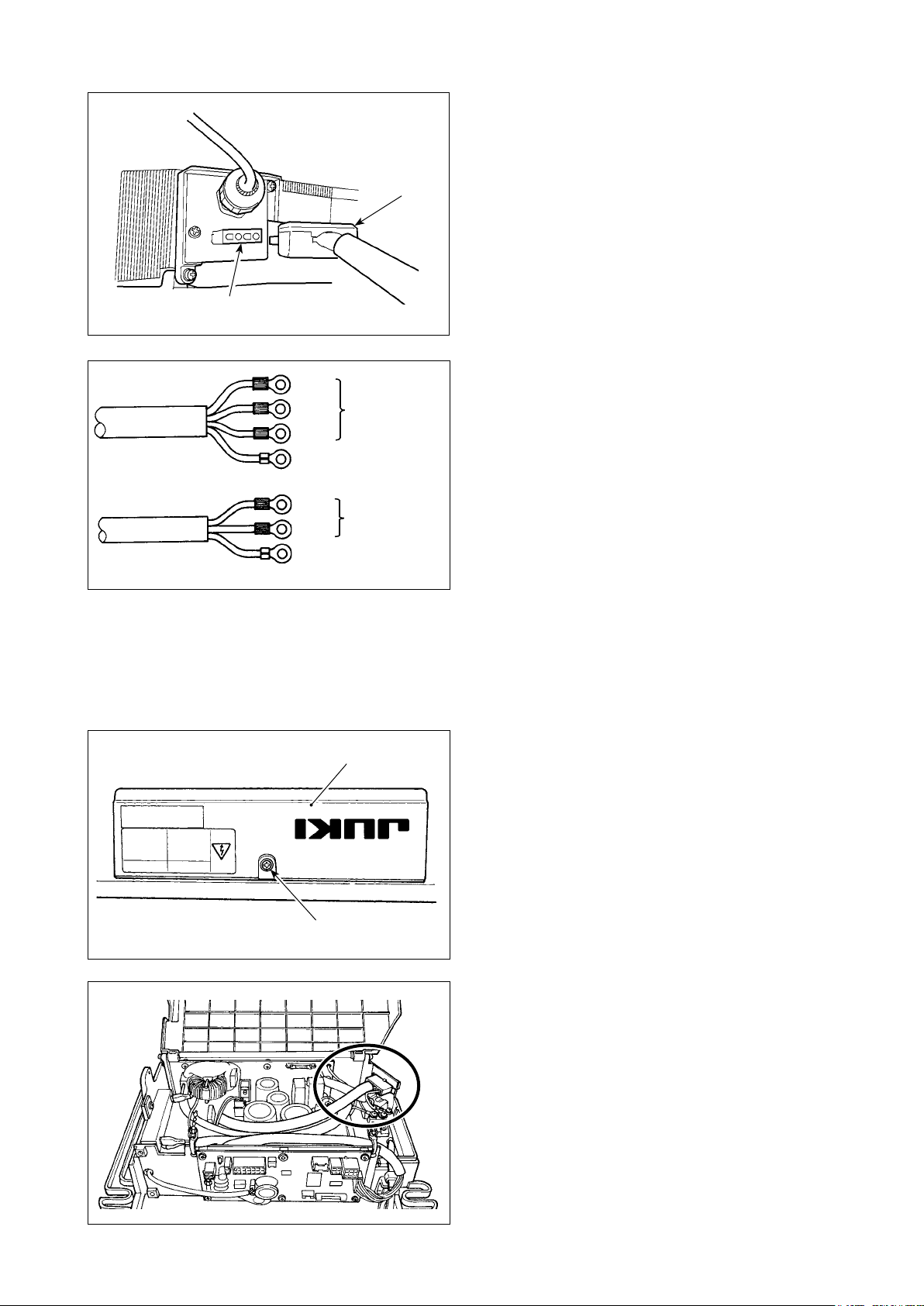
[ForCEspecicationsonly]
8) Connect connector 4P
to connector located
on the side of the box.
9) Connect motor output cord
of the power switch
to connector .
Connect motor output cord to connector locat-
ed on the side of the box.
CE 1ø 230V
Brown
Blue
Green/Yellow
(ground wire)
AC 220V-240V
[Installing power switch]
Connect power supply cord to the power switch.
[CEspecications]
Single phase 230V :
Power supply cords : brown, blue and green/yel-
low (ground wire)
– 7 –
Page 10
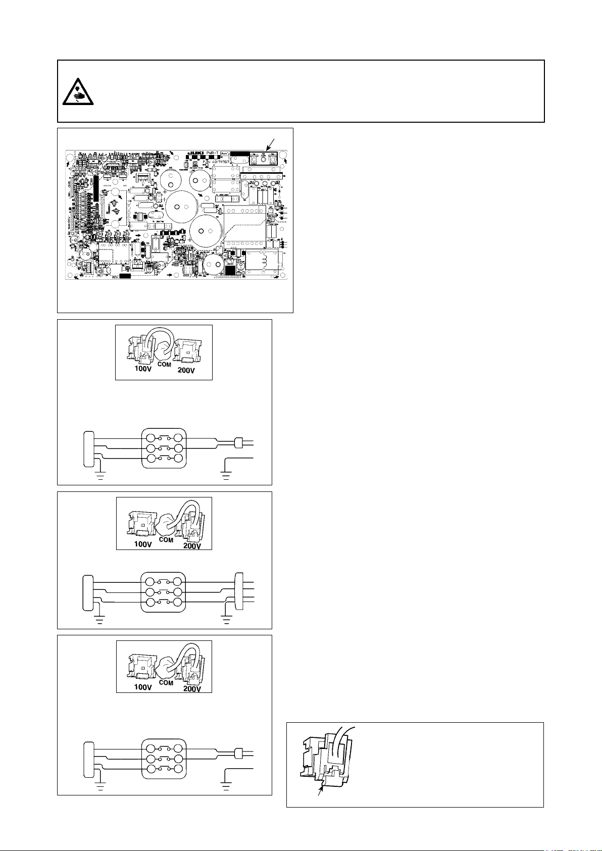
[Changing over the voltage between 100 V and 200 V]
WARNING :
To prevent personal injuries caused by electric shock hazards or abrupt start of the sewing machine,
carry out the work after turning OFF the power switch and a lapse of 5 minutes or more. To prevent
accidents caused by unaccustomed work or electric shock, request the electric expert or engineer of
our dealers when adjusting the electrical components.
* The illustration below shows the PWR-T PCB.
The type of PCB differs by destination.
A
Wiring for the single-phase 100 V
Be sure to connect the wire between 1 and 2.
If it is connected between 1-3 or 2-3, the sewing
machine will be inoperative.
(Box side)
WHITE
BLACK
RED
GREEN/
YELLOW
1
2
3
YELLOW
WHITE
BLACK
GREEN/
(Plug side)
B
Wiring for the 3-phase 200 V
(Box side)
WHITE
BLACK
RED
GREEN/
YELLOW
1
2
3
YELLOW
(Plug side)
WHITE
BLACK
RED
GREEN/
C
Wiring for the single-phase 200 V
Be sure to connect the wire between 1 and 2.
If it is connected between 1-3 or 2-3, the sewing
machine will be inoperative.
(Box side)
WHITE
BLACK
RED
GREEN/
YELLOW
1
2
3
YELLOW
WHITE
BLACK
GREEN/
(Plug side)
❶
By making the following two changes, the SC-923
can be used with three different power supplies, i.e.,
single-phase 100 - 120 V, single-phase 200 to 240 V
and 3-phase 200 to 240 V.
* Only the control box which uses PWR-T PCB can
be changed.
Replacement of the power cords
①
Changing-round of connector ❶ on the PWR
②
PCB
1) Turn OFF the power with the power switch after
checking that the sewing machine has stopped.
2) Draw out the power cord from the power receptacle after checking that the power switch has been
turned OFF. Then wait for 5 minutes or more.
3) Loosen the screws which are used to secure the
rear lid of the control box cover. Carefully open
the rear cover.
4) Changing procedure of the power voltage
(Caution) If the supply power changing is carried out in
a wrong manner, the control box can break.
Be extremely careful when taking the supply
voltage changing procedure.
A. To change over the supply voltage from 200 - 240
V to 100 - 120 V
•
Change the power cord with the JUKI genuine cord
with the part number (M90355800A0). Change
the earth cord with the one with the part number
(M90345800A0).
• Change over supply voltage changeover connector
mounted on the PWR PCB with the connector for 100
V.
•
Connect the crimp style terminal of AC input cord to
the power plug as shown in the gure A.
B, C. To change over the supply voltage from 100 -
120 V to 200 - 240 V
• Change the power cord with the JUKI genuine cord
with the part number (M90175800A0).
• Change over supply voltage changeover connector
mounted on the PWR PCB with the connector for 200
V.
•
Connect the crimp contact of the AC input cord to the
power plug as illustrated in Fig. B for the 3-phase power supply or as illustrated in Fig. C for the single-phase
one.
5) Before closing the rear lid of the cover, ascertain again
that the relevant parts have been correctly changed
without fail.
6) Close the read lid while pressing it, taking care not to
allow the wiring to be caught between the read lid of
the cover and the main body of the control box. Then,
secure the lid with the screws.
(Caution) Be sure to remove the con-
nector while holding its lock-
ingsectionwithyourngers.
Be extremely careful not to
pull the connector forcibly.
Locking section
❶
❶
– 8 –
Page 11
[In case of using the power switch for LA]
Connect motor output cord to connector locat-
ed on the side of the box.
JA 3ø 220V
JA 1ø 120V
Black
Red
White
Green/Yellow
(ground wire)
Black
White
Green/Yellow
(ground wire)
AC 200V-240V
AC 100V-120V
[Installing power switch]
Connect power supply cord to the power switch.
[JAspecications]
3-phase 220 V :
Power supply cords : black, white, red and green/
yellow (ground wire)
Single phase 120V :
Power supply cords : black, white and Green/Yel-
low (ground wire)
When the metallic conduit is used, be sure to change over the power cord section following the steps of pro-
cedure described below.
(Caution) Be sure to carry out this procedure before installing the control box on the machine table.
Place the control box with its frame side down on
①
A
the machine table as illustrated in the sketch.
Loosen screw
②
in underside cover A to open
B
the cover.
B
– 9 –
Change over the cord shown in the red-line circle
③
following the steps of procedure described below.
Page 12

C
D
Remove two screws
④
from the main body of the control box.
D
to remove clamping plate
C
F
F
E
G
Remove connector
⑤
section F with your ngers.
Turn connector
⑥
section.
E
to remove the cord locking
G
while holding its locking
H
D
– 10 –
Loosen nut
⑦
clamping plate D.
to remove the connector from
H
Page 13

I
J
D
Put locknut
⑧
the cord J from inside clamping plate D.
on the power cord and draw out
I
J
I
J
I
D
Install clamping plate
⑨
Pass power cord
⑩
Fix conduit
⑪
plate D placed between the locknuts.
with locknuts I with clamping
K
back to the control box.
D
through conduit K.
J
K
B
A
– 11 –
Close underside cover
⑫
with screw B.
and secure the cover
A
Page 14

10)
Make sure that the power switch is turned OFF
and insert power supply cord coming from the
power switch into the power plug socket.
(Caution) 1. Top end of power supply cord varies in
accordance with destination or supply
voltage. Check again the supply volt-
age and the voltage designated on the
control box when installing the switch.
2. Be sure to prepare power plug
formed to the safety standard.
3. Be sure to connect the ground wire
(green/yellow).
con-
3. Attaching the connecting rod
WARNING :
To protect against possible personal injury due to abrupt start of the machine, be sure to start the
following work after turning the power OFF and a lapse of 5 minutes or more.
❷
❸
B
A
❶
1) Fix connecting rod
to installing hole B of pedal
❶
lever ❷ with nut ❸.
2) Installing connecting rod
to installing hole A
❶
will lengthen the pedal depressing stroke, and the
pedal operation at a medium speed will be easier.
– 12 –
Page 15
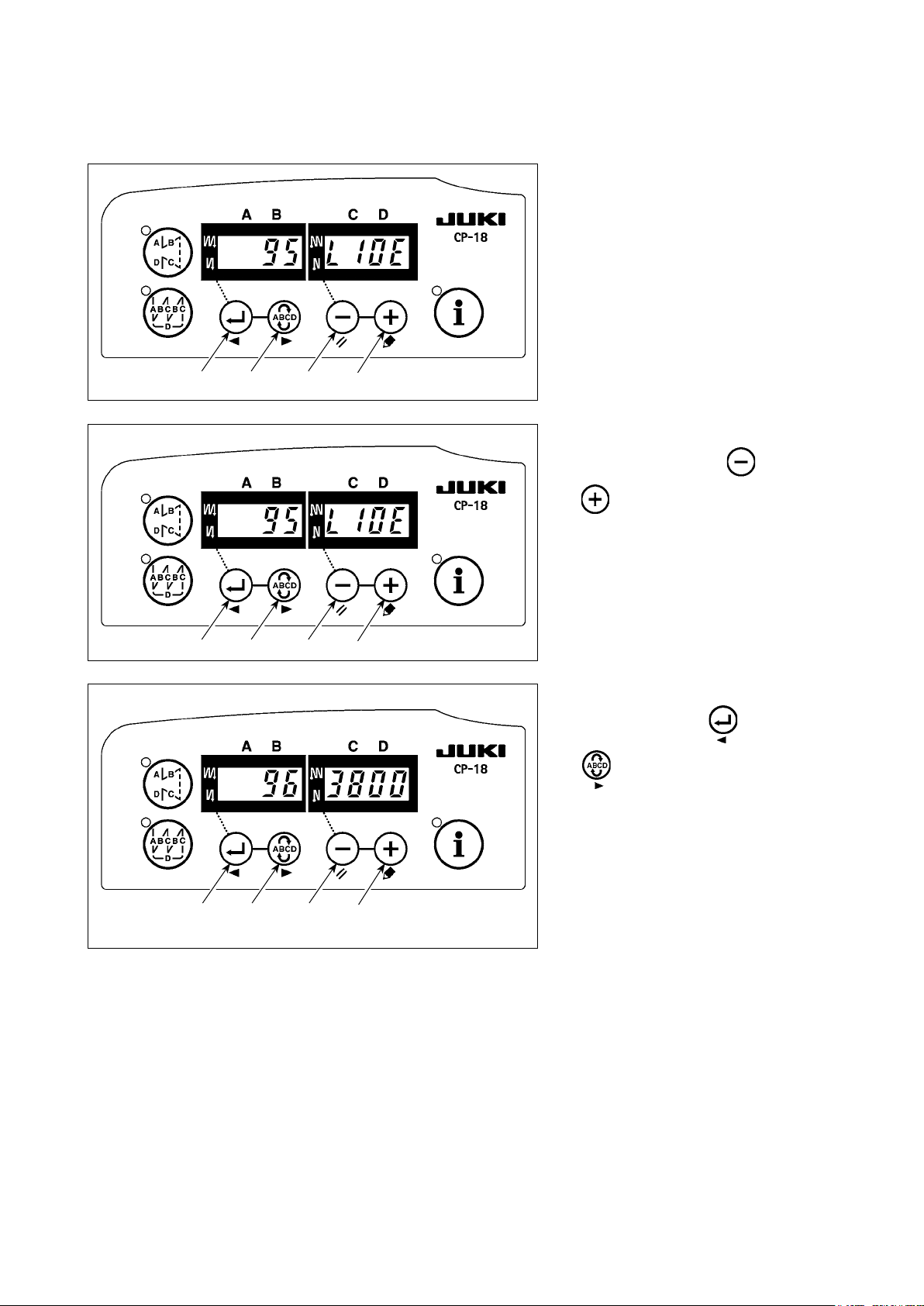
4. Setting procedure of the machine head
(Caution) For the operation panel other than CP-18, refer to the Instruction Manual for the operation panel
to be used for the setting procedure of the machine head.
1) Refer to "III-6. Setting of functions
of SC-923" p.24, and call the
function setting No. 95.
❺❹❸
❺❹❸
❻
❻
2) The type of machine head can be
selected by pressing switch
switch
* Refer to the "List of machine heads"
on the separate sheet or the Instruc-
tion Manual for the machine head of
your sewing machine for the type of
the machine head.
3) After selecting the type of machine
head, by pressing switch
switch
to 94 or 96, and the display automat-
ically changes to the contents of the
setting corresponding with the type
of machine head.
).
❻
), the step proceeds
❹
❸
❺
(
(
❺❹❸
❻
– 13 –
Page 16

5. Adjusting the machine head
(Caution) When the slip between the marker dot on the handwheel and the concave of the cover is exces-
sive after thread trimming, adjust the angle of the machine head by the operation below.
❸
Ⓐ
❺❹
❻
Ⓑ
1) Simultaneously pressing switch
and
❹
power switch.
2) is displayed (Ⓐ) in the indi-
cator and the mode is changed over
to the adjustment mode.
3) Turn the pulley of the machine head
by hand until the main-shaft ref-
erence signal is detected. At this
time, the degree of an angle from
the main-shaft reference signal is
displayed on the indicator Ⓑ. (The
value is the reference value.)
switch ❺, turn ON the
❽
❺❹❸
❻
❼
4) In this state, align marker dot
the pulley with recess ❽ on the pul-
ley cover.
5) Press switch ❻ to nish the
adjustment work. (The value is the
reference value.)
❼
on
❺❹❸
❻
– 14 –
Page 17

III. FOR THE OPERATOR
1. Operating procedure of the sewing machine
1) Press ON button
of the power switch to turn
❶
ON the power.
(Caution) If the power indication LED does not
light up even when turning ON the power
switch, immediately turn OFF the power
switch and check the voltage.
In addition, in such a case as this, re-turn
ON the power switch when 2 to 3 minutes
❷
❶
or more have passed after turning OFF
the power switch.
2) For some machine head installed, the needle bar automatically rotates to its upper position if the needle
bar is not there.
(Caution)WhenthepowertothesewingmachineisturnedONforthersttimeafterinstallation,itmay
require a longer time to get ready for operation since it carries out initialization procedure. In addition, be sure not to place hands or any other article under the needle since the needle bar may
move when the power is turned ON.
3) When depressing front part
of the pedal, the
❸
sewing machine rotates at the number of revolu-
❺
❹
❸
tions in accordance with the depressing amount.
When the pedal is returned to the neutral position, the sewing machine stops.
4) When lightly depressing back part
of the pedal,
❹
the presser goes up. (PFL type only)
5) When strongly depressing back part
of the
❺
pedal, thread trimming is performed.
❻
PFL KFL
Presser foot operation by pedal Enabled Disabled
Pedal depressing depth for
thread trimming
Deep Shallow
6) For some types of the sewing machine heads, it
is possible to program various sewing patterns,
using the operation panel, such as the reverse
feed stitching at sewing start and that at sewing
end. When you use CP-18 ❻ with your sewing
machine, refer to "III-3. Operating procedure of
the sewing pattern" p.17 for details. When
you use any other operation panel with your sewing machine, refer to the Instruction Manual for
the respective operation panel. (The gure given
illustrates the case of the LU-2810ES-7.)
❼
7) For some types of the sewing machine heads, reverse feed is performed by pressing touch-back
switch ❼. (The gure given illustrates the case
of the LU-2810ES-7.)
❷
8) When sewing is completed, press OFF button
of the power switch to turn OFF the power switch
after conrming that the sewing machine has
stopped.
– 15 –
❷
Page 18

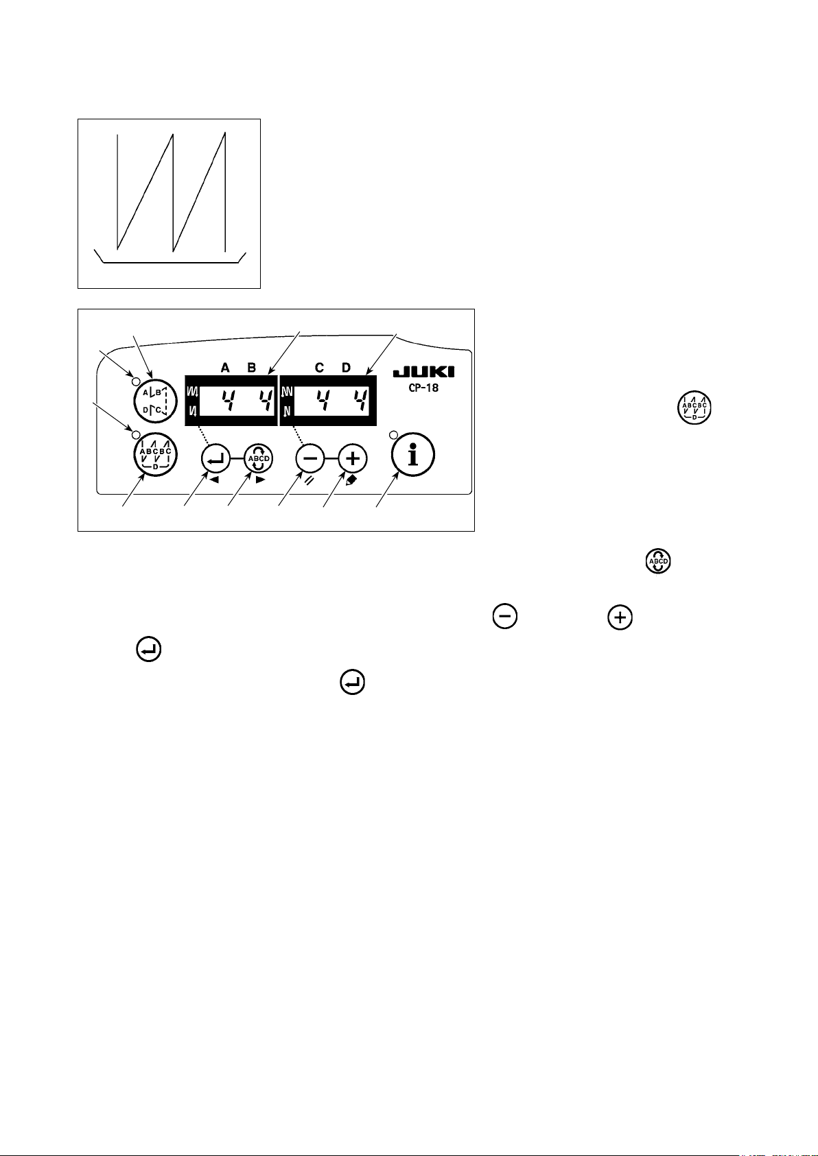
2. Operation panel (CP-18)
❶
❷
Ⓐ
❶
Ⓒ
Ⓓ
❷
switch : Used for changing over effective/ineffective of the reverse feed stitching pattern.
switch : Used for changing over effective/ineffective of the overlapped stitching pattern.
❸
❹
❺ ❻
Ⓑ
❼Ⓔ
❸
❹
* The selected process ashes ON and OFF.
❺
❻
❼
Indicators Ⓐ and Ⓑ : Various pieces of information are displayed.
LED Ⓒ : Lights up when the reverse feed stitching pattern is effective.
LED Ⓓ : Lights up when the overlapped stitching pattern is effective.
LED Ⓔ : Lights up when the production support function is displayed.
Flashes ON and OFF when invoking the one-touch setting.
switch : Used for conrming the contents of setting and for changing over effective/ineffective of
the reverse feed stitching at sewing start.
switch : Used for selecting the process (A, B, C, D) the number of stitches for which is to be
changed.
switch : Used for changing the content of the selected display (ashing section) and for changing
over effective/ineffective of the reverse stitch at sewing end.
switch : Used for changing the content of the selected display (ashing section).
switch : Used to call the production support function or one-touch setting (by keeping the switch
held pressed for one second).
– 16 –
Page 19

3. Operating procedure of the sewing pattern
(Caution) 1. For the operation panel other than CP-18, refer to the Instruction Manual for the operation
panel to be used.
2. For some machine heads, reverse-stitching pattern cannot be used.
(1) Reverse feed stitching pattern
Reverse feed stitching at sewing start and reverse feed stitching at sewing end can be separately pro-
grammed.
[Setting procedure of the reverse feed
stitching]
Ⓒ
❶
Ⓐ
Ⓑ
1) Effective/ineffective of the reverse
feed stitching pattern can be changed
Ⓓ
over by pressing
switch
❶
When the reverse feed stitching
pattern is rendered effective, LED Ⓒ
lights up, the number of stitches of
the reverse feed stitching at sewing
❷
❺❹❸
❻
❼
start is displayed on indicator Ⓐ, and
the number of stitches of the reverse
feed stitching at sewing end is dis-
played on indicator Ⓑ.
Select a process (A, B, C or D) the number of stitches for which is to be changed by using switch
The number which is ashing ON and OFF represents the process which is being set.
Change the number of stitches for the selected process by using switch
Press switch
to conrm the change you have made. (The number of stitches that can be set is 0
❸
❺
and
switch
❻
.
.
.
❹
to 15.)
(Caution) The sewing machine cannot perform sewing when the display of the number of stitches for a
processisashingONandOFF.
2) When the number of reverse feed
Ⓓ
Ⓒ
❶
Ⓐ
Ⓑ
stitches display is not ashing ON
and OFF, every press on
changes over the reverse feed
❸
switch
stitching mode from the "reverse feed
stitching at sewing start," "double
reverse feed stitching at sewing start"
and "no reverse feed stitching at
sewing start."
❷
❺❹❸
❻
❼
In addition, every time switch
is pressed, the reverse feed stitch-
Without reverse
stitching :
Reverse
stitching :
ing feature changes over from the
reverse feed stitching at sewing end
to the double reverse stitch at sewing
Double reverse
stitching :
end, then to no reverse feed stitching
at sewing end, in turn.
❺
– 17 –
Page 20
(2) Overlapped stitching pattern
Overlapped stitching pattern can be programmed.
Ⓓ
Ⓒ
A
C
C
B : Number of stitches of reverse stitching setting .....0 to 15 stitches
C : Number of stitches of normal stitching setting ...... 0 to 15 stitches
D : Number of times of repetition ................................ 1 to 9 times
A : Number of stitches of normal stitching setting.......0 to 15 stitches
(Caution)WhenprocessDissetto5times,thesewingisrepeatedasA→
B→C→B→C.
B
B
D
[Setting procedure of the overlapped
❶
Ⓐ
Ⓑ
stitching]
1) Effective/ineffective of the over-
lapped stitching pattern can be
changed over by pressing
switch ❷.
When the overlapped stitching pat-
tern is rendered effective, LED
Ⓓ
lights up.
❷
❺❹❸
❻
❼
2) Select a process (A, B, C or D) the number of stitches for which is to be changed by using switch
❹
The number which is ashing ON and OFF represents the process which is being set.
3) Change the number of stitches for the selected process by using switch
4) Press switch
setting has been conrmed by pressing
(Caution) The overlapped stitching pattern is carried out under automatic operation mode. Once the pedal
is depressed, the sewing machine will automatically perform sewing of the number of over-
lapped stitches.
to conrm the change you have made. (The sewing machine does not run unless the
❸
switch
❸
.)
❺
and
switch
❻
.
.
– 18 –
Page 21

4. One-touch setting
A part of function setting items can be easily changed in the normal sewing state.
(Caution) For the setting of functions other than those covered in this part, refer to "III-6. Setting of
functions of SC-923" p.24.
[One-touch setting procedure]
Ⓒ
❶
Ⓐ
Ⓑ
1) Keep switch
held pressed
❼
for one second to place the panel in
the function setting mode.
Ⓓ
❷
❻❺❹❸
Ⓔ
❼
2) Change over the item to be set by
using switch
. Then, the set value can be
❹
changed by using
switch
❻
❸
or
switch
switch
.
3) To return to the normal sewing state,
(Caution)Thesettingisconrmedbypressing switch
Thread trimming function ( )
①
❼
.
press switch
❼
.
: Thread trimming operation is not performed (solenoid output prohibition: thread trimmer)
: Thread trimming operation is effective.
One-shot automatic stitching function ( )
②
: One-shot automatic stitching function is ineffective.
: One-shot automatic stitching is effective.
(Caution) This function is rendered effective when the material end sensor function is set. It is not pos-
sible to prohibit the one-shot operation during overlapped sewing operation. The number of
revolution is the value which is set for setting No. 38.
❺
and
Setting of the max. speed of stitch ( )
③
The highest speed of stitch of the machine head is set. The upper limit of the set value differs with the
type of machine head to which the SC is connected.
Setting range : 150 - Max. value [sti/min]
Material end sensor function ( )
④
: Material end sensor function is ineffective.
: Once the material end is detected, the sewing machine stops running after having sewn the number
of stitches set with ⑦ (
).
* This function is rendered effective when the material edge sensor is set with function setting No. 12.
Thread trimming function by material end sensor ( )
⑤
: Automatic thread trimming function after the detection of material end is ineffective.
: Once the material end is detected, the sewing machine performs thread trimming after having sewn
the number of stitches set with ⑦ (
).
* This function is rendered effective when the material edge sensor is set with function setting No. 12.
– 19 –
Page 22

Number of stitches for material end sensor ( )
⑥
The number of stitches to be sewn from the detection of material end to the stop of the sewing machine
Number of stitches that can be set: 0 to 19 (stitches)
(Caution)Ifthenumberofstitchesspeciedisinadequate,thesewingmachinecanfailtostopwithin
the preset number of stitches depending on the number of revolutions of the sewing machine.
Adjustment of the quantity of light of LED lamp ( )
⑦
Used to adjust the quantity of light of LED lamp (optional)
Setting range : 0 to 100%
Optical sensor function ( )
⑧
: Optical sensor function is disabled.
: After the optical sensor input, the sewing machine is stopped after the sewing of the number of
stitches set with ⑫ (
).
* This function is enabled when the optical sensor is set with function setting No. 12.
Optical sensor lter function ( )
⑨
: Optical sensor lter function is disabled.
: After the optical sensor detection, the input is delayed until the sewing machine has completed the
sewing of the number of stitches set with ⑪ (
).
* This function is enabled when the optical sensor is set with function setting No. 12.
Number of stitches for the optical sensor lter ( )
⑩
Used to set the number of stitches for delaying the time at which the optical sensor input status takes
effect.
Setting range: 0 to 99 stitches
* This function is enabled when the optical sensor is set with function setting No. 12.
Number of stitches to stop the optical sensor ( )
⑪
Used to set the number of stitches to be sewn from the optical sensor input to the stop of the sewing ma-
chine.
Setting range: 0 to 99 stitches
* This function is enabled when the optical sensor is set with function setting No. 12.
(Caution) If a small number is set, the sewing machine may not be stopped within the set number of
stitches depending on the number of revolutions of the sewing machine.
Number of times of optical sensor detection ( )
⑫
The sewing machine stops every time the optical sensor input is turned ON and carries out automatic
thread trimming when the set number of times is reached.
Setting range: 1 to 15 times
* This function is enabled when the optical sensor is set with function setting No. 12.
Pedal depressing speed limiting function ( )
⑬
This function limits the pedal depressing speed at the time of the optical sensor input.
0 : The function is disabled.
1 : Fixed at the one-shot speed (function setting No. 38)
2 : Limited to the one-shot speed (function setting No. 38)
3 : When the optical sensor is enabled, the sewing machine runs under the automatic mode upon
depress on the pedal.
* This function is enabled when the optical sensor is set with function setting No. 12.
– 20 –
Page 23

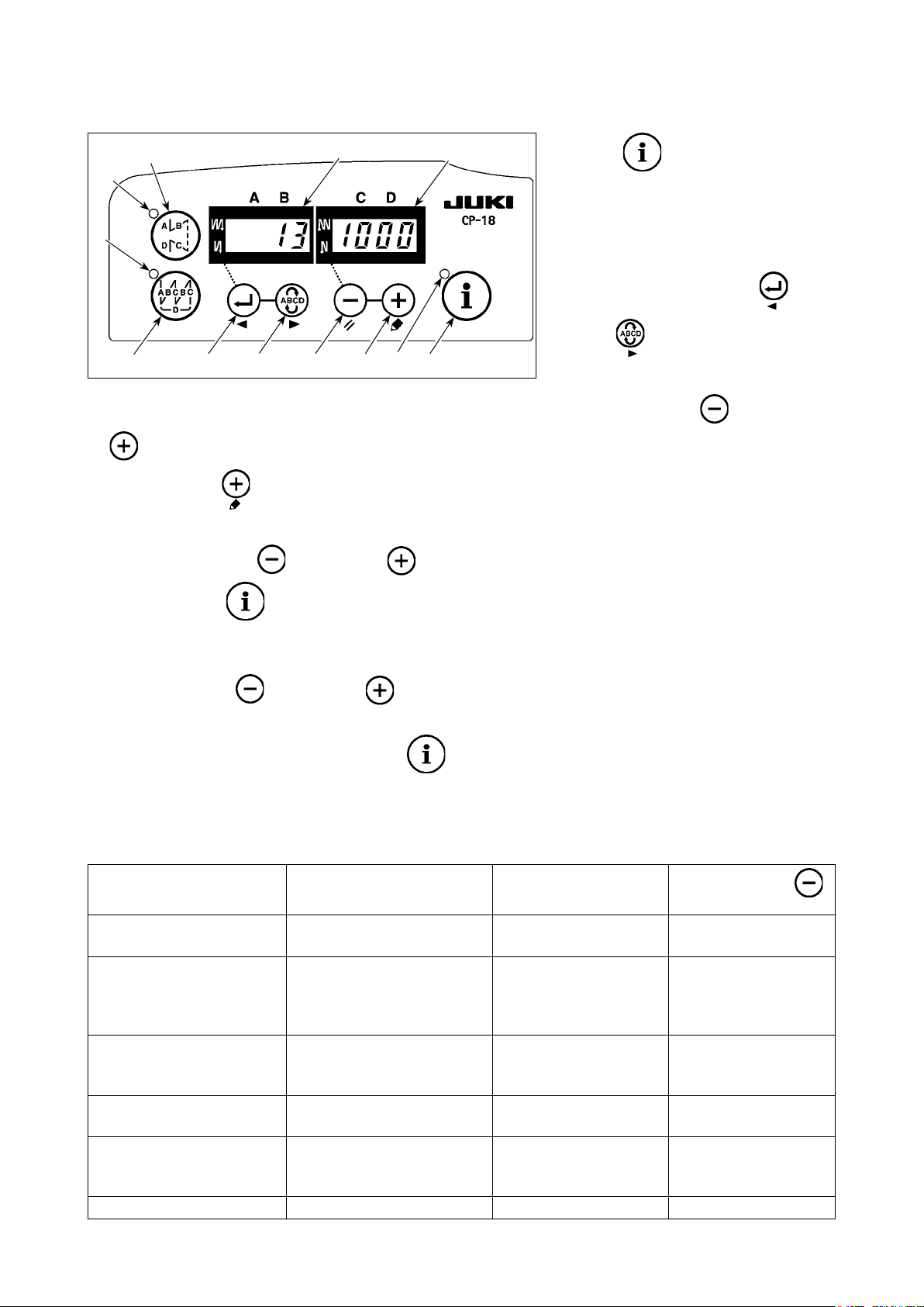
5. Production support function
The production support function consists of three different functions (six different modes) such as the produc-
tion volume management function, operation measuring function and bobbin counter function. Each of them
has its own production support effect. Select the appropriate function (mode) as required.
Production volume management function
■
Target number of pcs. display mode [F100]
Target/actual number of pcs difference display mode [F200]
The target number of pieces, actual number of pieces and the difference between the target and actu-
al number of pieces along with the operation time are displayed to notify the operators of a delay and
advance in real time. Sewing machine operators are allowed to engage sewing while constantly checking
his/her work pace. This helps raise target awareness, thereby increasing productivity. In addition, a delay
in work can be found at an early stage to enable early detection of problems and early implementation of
corrective measures.
Operation measuring function
■
Sewing machine availability rate display mode [F300]
Pitch time display mode [F400]
Average number of revolutions display mode [F500]
Sewing machine availability status is automatically measured and displayed on the control panel. The
data obtained can be used as basic data to perform process analyses, line arrangement and equipment
efciency checkup.
Bobbin counter function
■
Bobbin counter display mode
In order to change bobbins before the current bobbin runs out of thread, the time for replacing the bobbin
is notied.
[To display the production support modes]
❶
Ⓐ
Ⓑ
Ⓒ
Ⓓ
❷
(Caution) F100 to F500 modes have been factory-set to HIDE at
the time of delivery.
The bobbin counter display mode is changed over
between display/hide by setting the bobbin counter
function (function setting No. 6). (It has been facto-
ry-set to ON at the time of shipment.)
❻❺❹❸
❼
Keep
switch
held pressed (one
❼
second) in the normal sewing state to
call the one-touch setting screen.
Then, press
switch
❶
or
switch ❷ on the one-touch setting
screen to display/hide the production
support modes.
Select the mode to be displayed/hidden
by pressing
. ON/OFF of the display can be
❹
switch
changed over by pressing
or
switch
❻
.
❸
or
switch
switch
❺
To return to the normal sewing state,
press
switch
❼
.
– 21 –
Page 24
Sewing can be performed with the production support data displayed on the control panel.
[Basic operation of the production support modes]
is pressed
❼
Ⓒ
❶
Ⓐ
Ⓑ
1) When switch
in the normal sewing state, LED Ⓔ
lights up to enter the production sup-
Ⓓ
port mode.
2) Production support function can be
changed over by pressing switch
❷
❻❺❹❸
Ⓔ
❼
3) Data attached marked with (*1) in Table 1 "Indicator
switch
4) When you keep switch
❻
.
held pressed for two seconds, indicator Ⓑ and LED Ⓔ ash ON and OFF.
❻
or
❸
" can be changed by means of
Ⓐ
switch
❹
.
switch
While they are ashing ON and OFF, data marked with (*2) in Table 1 "Display under modes" can be
changed by pressing
switch
When you press switch
and
❺
, the value marked with (*2) is conrmed and indicator Ⓑ and LED Ⓔ
❼
switch
❻
.
❺
and
stop ashing ON and OFF.
5) The value with a sharp mark (*3) in Table 1 "Display of modes" can be changed only immediately after
resetting by using switch
❺
and
switch
❻
.
6) Refer to the table "Mode resetting operation," for the resetting procedure of data.
7) To return to the normal sewing state, press switch
❼
.
Data to be displayed under the respective modes are as described in the table below.
Table 1: Display of modes
Mode name Indicator
Target number of pcs. display mode [F100]
Target/actual number of pcs.
difference display mode
[F200]
Sewing machine availability
rate display mode [F300]
Pitch time display mode
[F400]
Average number of revolutions display mode [F500]
Bobbin counter display mode bbn Bobbin counter value (*3) -
Actual number of pieces
(Unit : piece)
Difference between target
number of pieces and actual
number of pieces
(d : piece) (*1)
oP-r Sewing machine avail-
Pi-T Pitch time in the previous
ASPd Average number of rev-
Ⓐ
(*1)
Indicator
Target number of pieces
(Unit : piece)
Target pitch time
(Unit : 100 msec) (*2)
ability rate in the previous
sewing (Unit : %)
sewing (Unit : 1 sec)
olutions in the previous
sewing (Unit : sti/min)
Ⓑ
(*2)
Indicator Ⓑ (when
switch ❺ is pressed)
-
-
Display of average
availability rate of sewing machine (Unit : %)
Display of average pitch
time (Unit : 100 msec)
Display of average
number of revolutions
(Unit : sti/min)
– 22 –
Page 25

Table 2: Mode resetting operation
Mode name Switch
Target number
of pcs. display
mode [F100]
Target/actu-
al number of
pcs. difference
display mode
[F200]
Sewing machine
availability rate
display mode
[F300]
Pitch time
display mode
[F400]
Average number of revolutions display
mode [F500]
Bobbin counter
display mode
Resets the actual number of pieces
Resets the difference between target number of pieces and actual number of pieces
Resets the actual number of pieces
Resets the difference between target number of pieces and actual number of pieces
Resets average availability rate of sewing
machine
Resets average pitch time Resets average availability rate of sewing machine.
Resets average number of revolutions of
sewing machine.
Resets the bobbin counter value
(Note that only the bobbin counter is imme-
(held pressed for 2 seconds)
❺
Switch
Resets average availability rate of sewing machine.
Resets average pitch time.
Resets average number of revolutions of sewing
machine.
Resets average pitch time.
Resets average number of revolutions of sewing
machine.
Resets average availability rate of sewing machine.
Resets average pitch time.
Resets average number of revolutions of sewing
machine.
(held pressed for 4 seconds)
❺
-
-
-
diately reset by pressing
switch
❺
.)
[Detailed setting of production volume management function [F101], [F102]]
When switch
three seconds) under the target number of
pcs. display mode [F100] or the target/actual
number of pcs. difference display mode [F200],
the detailed setting of the production volume
management function can be carried out.
The setting state of the number of times of
thread trimming [F101] and that of the target
achievement buzzer [F102] can be changed
over by pressing
.
❹
❷
❶
❺❹❸
❻
❼
Setting of production volume management function
F101 Setting of the number
of times of thread
trimming
F102 Operation to be done
when the target is
achieved
The number of times of thread trimming to be performed during the sewing of one
piece of material is set.
0 : The production volume is counted by pressing the push switch. The production
volume is not counted by thread trimming.
1~ : One is added to the actual number of pieces counter upon completion of the set
number of times of thread trimming.
The operation to be carried out when the actual number of pieces has reached the
target number of pieces is set.
0 : No operation
1 : The buzzer sounds
2 : The sewing machine will not run even if the pedal is depressed.
is held pressed (for
❼
❸
or
switch
switch
The actual number of pieces counter is reset to zero (0) by keeping
held pressed when the sewing machine is forcedly at rest. Then, the operation of the
sewing machine is enabled again.
switch
❺
– 23 –
Page 26

6. Setting of functions of SC-923
Functions can be selected and specied.
(Caution) For the function setting procedure of any operation panel other than CP-18, refer to the Instruc-
tion Manual for the operation panel to be used.
Ⓓ
Ⓓ
Ⓒ
Ⓒ
Ⓒ
❷
❷
❶
❶
❶
ⒷⒶ
1) Turn ON the power with switch
held pressed.
❼
(The item which has been changed
during the previous work is displayed.)
* If the screen display does not
change, re-carry out operation described in step 1).
(Caution)
Be sure to re-turn ON the power
❻❺❹❸
Ⓔ
❼
ⒷⒶ
switch when one or more seconds
have passed after turning it OFF. If
the power switch is re-turned ON
immediately after turning it OFF,
the sewing machine may fail to operate normally. In such a case, be
sure to turn ON the power switch
again properly.
2) To move the setting No. forward,
press switch
setting No. backward, press
. To move the
❹
switch ❸.
❻❺❹❸
Ⓔ
❼
(Caution)
If the setting No. is moved forward
ⒷⒶ
(or backward), the previous (or
subsequent) content of the setting
isconrmed.Becarefulwhenthe
content of a setting is changed
Ⓓ
(when the
touched).
/
switch is
Example) Changing the maximum num-
ber of revolutions (setting No. 96)
Press switch ❸ or switch
❷
❻❺❹❸
Ⓔ
❼
to call setting No. "96."
❹
The current set value is displayed on
indicator Ⓑ.
Press switch
* The content of setting of the setting No. returns to the initial value by pressing switch
to change the set value to "2500".
❺
❺
and
switch ❻ simultaneously.
3) After completion of the changing procedure, press switch
❸
or
switch
to conrm the updated
❹
value.
(Caution) If the power is turned OFF before carrying out this procedure, the changed content is not updat-
ed. When
When
After completion of the operation, the machine is returned to the normal sewing state by turning
OFF the power and re-turning it ON.
switch
switch
is pressed, the display on the panel changes to the previous setting No.
❸
is pressed, the display on the panel changes to the subsequent setting No.
❹
– 24 –
Page 27

❶
ⒷⒶ
In the case the screen shown at the left
is displayed by the operation described
in 1) on the previous page, the screen is
locked by the password.
Refer to the Engineer's Manual for how
to set and reset the password.
❷
❻❺❹❸
❼
– 25 –
Page 28
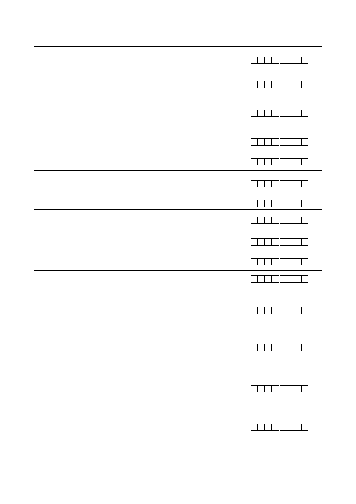
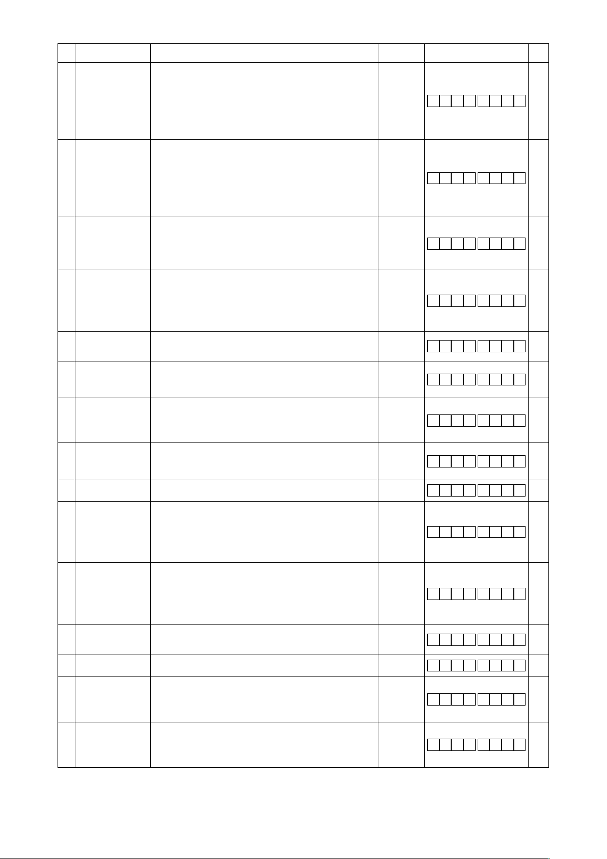
7. Function setting list
No Item Description
1 Soft start function The number of stitches to be sewn at a low speed when the soft-
2 Material end sensor
function
3 Thread trimming
function by material
end sensor
4 Number of stitches
for material end
sensor
6 Bobbin thread
counting function
* 7 Unit of bobbin thread
counting down
* 8 Number of rotation of
reverse feed stitching
9 Thread trimming
prohibiting function
10 Setting of needle bar
stop position when
the sewing machine
stops.
11 Operation
conrmation sound
for operation panel
12 Optional switch
function selection
* 13 Function of
prohibiting start of
the sewing machine
by bobbin thread
counter
14 Sewing counter Counting function of sewing (number of completion of process)
21 Function of neutral
presser lifting
22 Needle up/down
correction switch
changeover function
start function is used at the start of sewing.
0 : The function is not selected.
1 to 9 : The number of stitches to be sewn under the soft-start
mode.
Material end sensor function (to be used only with CP-18).
0 : Material end detection function is not operative.
1 : After detecting material end, the specied number of stitches
(No. 4) will be sewn, and the sewing machine will stop.
Thread trimming function by material end sensor (to be used only
with CP-18).
0 : Automatic thread trimming function after detection of material
end is not operative.
1 : After detecting material end, the specied number of stitches
(No. 4) will be sewn, and the sewing machine will stop and
perform automatic thread trimming.
Number of stitches for material end sensor (to be used only with
CP-18).
Number of stitches from detection of material end to stop of the
sewing machine.
Bobbin thread counting function
0 : Bobbin thread counting function is not operative.
1 : Bobbin thread counting function is operative.
Unit of bobbin thread counting down
0 : 1 Count/10 stitches
1 : 1 Count/15 stitches
2 : 1 Count/20 stitches
3 : 1 Count/thread trimming
Sewing speed of reverse feed stitching 150 to 3,000
Thread trimming prohibiting function (to be used only with CP-18).
0 : Thread trimming is effective.
1 : Thread trimming is prohibited.
(Output of solenoid is prohibited. : Thread trimmer)
Position of needle bar is specied when the sewing machine
stops.
0: The needle bar stops at its lower position.
1: The needle bar stops at its upper position.
Operation conrmation sound for operation panel
0 : Operation conrmation sound is not generated
1 : Operation conrmation sound is generated.
Switching of function of optional switch.
Refer to "III-8. Detailed explanation of selection of functions"
p.32.
Function of prohibiting start of the sewing machine by bobbin
thread counting
0 : When counting is out (0 or less) Function of prohibiting start
of the sewing machine is not operative.
1 : When counting is out (0 or less) Function of prohibiting start
of the sewing machine after thread trimming is operative.
2 : When counting is out (0 or less), the sewing machine stops
once. Function of prohibiting start of the sewing machine
after thread trimming is operative.
0 : Sewing counter function is not operative.
1 : Sewing counter function is operative. (Every time thread
trimming is performed)
2 : With the sewing counting switch input function
Function of needle up/down compensating switch on the
operation panel can be changed.
0 : Needle up/down compensation
1 : Provided with selectable function of automatic presser foot
lifting at neutral position of pedal
2 : Provided with the function of automatic presser foot lifting at
neutral position of pedal when enabled and added with the
function of conducting alternate operation by depressing the
back part of pedal
(This function is disabled when No. 93 Needle up/down switch
additional function setting is "3")
Function of the needle up/down correction switch is changed
over.
0 : Needle up/down compensation
1 : One stitch compensation
Setting
range
0 to 9
(stitches)
0/1
0/1
0 to 19
(stitches)
0/1
0 to 3
(sti/min)
0/1
0/1
0/1
0 to 2
0 to 2
0 to 2
0/1
Indication of function setting
1
2
3
4
6
7
8
6 0 0
9
1 0
1 1
1 2 o P T _
1 3
1 4
2 1
2 2
Ref.
page
32
1
32
0
32
0
32
5
32
1
0
32
0
32
0
32
1
33
0
38
1
38
0
38
0
* Do not change the set values with asterisk (*) mark as they are functions for maintenance. If the standard set value set at the time of
delivery is changed, it is in danger of causing the machine to be broken or the performance to be deteriorated.
If it is necessary to change the set value, please purchase the Engineer’s Manual and follow the instructions.
– 26 –
Page 29

No Item Description
25 Thread trimming
operation after
turning the
handwheel by hand
30 Function of reverse
feed stitching on the
way
31 Number of stitches of
reverse feed stitching
on the way
32 Effective condition of
reverse feed stitching
on the way when the
sewing machine is
stopping.
33 Thread trimming
function by reverse
feed stitching on the
way
* 35 Number of rotation at
a low speed
* 36 Number of rotation of
thread trimming
37 Number of rotation of
soft-start
38 One-shot speed One-shot speed (The max. value depends on the number of
* 39 Pedal stroke at the
start of rotation
* 40 Low speed section of
pedal
* 41 Starting position of
lifting presser foot by
pedal
* 42 Starting position of
lowering presser foot
* 43 Pedal stroke 2 for
starting thread
trimming
* 44 Pedal stroke
for reaching the
maximum number of
rotation
* 45 Compensation of
neutral point of the
pedal
* 48 Pedal stroke 1 for
starting thread
trimming
49 Lowering time of
presser foot
50 Pedal specication Type of pedal sensor is selected.
51 Compensation of
ON timing of reverse
feed stitching at the
start of sewing
52 Compensation
of OFF timing of
reverse feed stitching
at the start of sewing
53 Compensation
of OFF timing of
reverse feed stitching
at the end of sewing
Thread trimming operation after moving the needle away from
its upper or lower position by turning the handwheel by hand is
specied.
0 : Thread trimming operation is carried out after turning the
handwheel by hand
1 : Thread trimming operation is not carried out after turning the
handwheel by hand
Function of reverse feed stitching on the way
0 : Normal one-touch type reverse feed stitching function
1 : Function of reverse feed stitching on the way is operative.
Number of stitches of reverse feed stitching on the way.
Effective condition of reverse feed stitching on the way
0 : Function is not operative when the sewing machine stops.
1 : Function is operative when the sewing machine stops. 0/1
Thread trimming function by reverse feed stitching on the way
0 : Automatic thread trimming function after completion of
reverse feed stitching on the way is not operative.
1 : Automatic thread trimming after completion of reverse feed
stitching on the way is performed.
Lowest speed by pedal
(The MAX value differs by machine head.)
Thread trimming speed
(The MAX value differs by machine head.)
Sewing speed at the start of sewing (soft-start)
(The MAX value differs by machine head.)
rotation of the sewing machine head.)
Position where the sewing machine starts rotating from pedal
neutral position (Pedal stroke)
Position where the sewing machine starts accelerating from pedal
neutral position (Pedal stroke)
Position where the cloth presser starts lifting from pedal neutral
position (Pedal stroke)
Starting position of lowering presser foot
Stroke from the neutral position
Position 2 where the thread trimming starts from pedal neutral
position (When the function of lifting presser foot by pedal is
provided.) (Pedal stroke)
(Effective only when Item No. 50 is set at 1.)
Position where the sewing machine reaches its highest sewing
speed from pedal neutral position (Pedal stroke)
Compensation value of the pedal sensor
Position where thread trimming starts from pedal neutral position
(Standard pedal) (Pedal stroke)
(Effective only when Item No. 50 is set at 0.)
Lowering time of presser foot after the pedal has been depressed.
(Start of rotation of the sewing machine is delayed during this
time.)
0 : KFL
1 : PFL
Refer to "III-10.Selectionofthepedalspecications"p.47.
Compensation of ON starting for reverse feed stitching when
reverse feed stitching at the start of sewing is performed. – 36 to 36
Compensation of OFF releasing for reverse feed stitching when
reverse feed stitching at the start of sewing is performed. – 36 to 36
Compensation of OFF releasing for reverse feed stitching when
reverse feed stitching at the end of sewing is performed. – 36 to 36
Setting
range
0/1
0/1
0 to 19
(stitches)
0/1
150 to MAX
(sti/min)
100 to MAX
(sti/min)
100 to MAX
(sti/min)
150 to MAX
(sti/min)
200 to 1600
200 to 3000
– 900 to
–200
160 to 1600
– 900 to
–200
200 to 4500
–1500 to
1500
– 900 to
–200
0 to 500
(ms)
0/1
(10°)
(10°)
(10°)
Indication of function setting
2 5
3 0
3 1
3 2
3 3
3 5
3 6
3 7
2 0 0
1 7 0
2 0 0
3 8 1 5 0 0
3 9
9 0 0
4 0 1 8 0 0
4 1 – 3 7 0
4 2
3 0 0
4 3 – 6 5 0
4 4 4 4 9 0
4 5
4 8 – 4 3 0
4 9
5 0
5 1
5 2
5 3
1 4 0
2 7
Ref.
page
1
39
0
39
4
39
0
39
0
32
39
0
1
40
40
7
40
8
* Do not change the set values with asterisk (*) mark as they are functions for maintenance. If the standard set value set at the time of
delivery is changed, it is in danger of causing the machine to be broken or the performance to be deteriorated.
If it is necessary to change the set value, please purchase the Engineer’s Manual and follow the instructions.
– 27 –
Page 30

No Item Description
55 Foot lift after thread
trimming
56 Reverse revolution
to lift the needle after
thread trimming
58 Needle bar home
position retaining
function
59 Function of Auto/
Manual change-
over of reverse feed
stitching at the start
of sewing
60 Function of stop
immediately after
reverse feed stitching
at the start of sewing
61 Needle bar home
position retaining
time
64 Change-over speed
of condensation
stitch or EBT (end
back tack)
71 Double reverse feed
stitching function
72 Sewing machine
startup selecting
function
76 One-shot function One-shot operation up to the material end is specied. (to be
87 Function of pedal
curve selection
Function of lifting presser foot at the time of (after) thread trimming
0 : Not provided with the function of automatic lifting of work-
clamp after thread trimming
1 : Provided with the function of lifting presser foot automatically
after thread trimming
Function of reverse revolution to lift the needle at the time of
(after) thread trimming
0 : Not provided with the function of reverse revolution to lift the
needle after thread trimming
1 : Provided with the function of reverse revolution to lift the
needle after thread trimming
Needle bar home position retaining function
0 : Needle bar home position retaining function is disabled
1 : Needle bar home position retaining function is enabled (hold-
ing force is weak.)
2 : Needle bar home position retaining function is enabled (hold-
ing force is medium.)
3 : Needle bar home position retaining function is enabled (hold-
ing force is strong.)
This function can specify the sewing speed of reverse feed stitching at the start of sewing.
0 :
The speed will depend on the manual operation by pedal, etc.
1 : The speed will depend on the specied reverse feed stitching
speed (No. 8).
Function at the time of completion of reverse feed stitching at the
start of sewing
0 : Not provided with the function of temporary stop of the
sewing machine at the time of completion of reverse feed
stitching at the start of sewing
1 : Provided with the function of temporary stop of the sewing
machine at the time of completion of reverse feed stitching at
the start of sewing.
Sets the period of time in which the needle bar is retained at its
home position after the sewing machine has stopped.
0 : The function is disabled (the needle bar home position
retaining function is enabled at all times)
100 - 3000 ms
Initial speed when starting condensation stitch or EBT
Effective/ineffective of double reverse feed stitching is changed
over. (to be used only with CP-18)
0 : Ineffective
1 : Effective
Current limit at the startup of sewing machine is specied.
: No limit to the start-up acceleration
0
1 to 250 : Restricted amount of the start-up acceleration
used only with CP-18)
: One-shot operation is not performed.
0
: One-shot operation is performed.
1
Pedal curve is selected. (Improving pedal inching operation)
1 to 10
Number of rotations
0
–1 to –10
Setting
range
0/1
0/1
0 to 3
0/1
0/1
0 : Disabled
100 to 3000
(ms)
0 to 250
(sti/min)
0/1
0 to 250
0/1
– 10 to 10
Indication of function setting
5 5
5 6
5 8
5 9
6 0
6 1
6 4
7 1
7 2
7 6
8 7
5 0
2 3 7
Ref.
page
40
1
41
1
41
1
41
1
41
0
41
0
1
42
32
0
42
0
Pedal stroke
90 Initial sewing-
machine travel
function
91 Function of
prohibiting
compensation
operation after
turning handwheel by
hand
92 Function of reducing
speed of reverse
feed stitching at the
start of sewing
* Do not change the set values with asterisk (*) mark as they are functions for maintenance. If the standard set value set at the time of
delivery is changed, it is in danger of causing the machine to be broken or the performance to be deteriorated.
If it is necessary to change the set value, please purchase the Engineer’s Manual and follow the instructions.
The function for automatically moving the sewing machine to a
specied position immediately after turning the power ON.
0 : The function is disabled (Find the origin by stepping before
the pedal)
1 : Sewing machine is initially stopped with its needle up
2 : Sewing machine is initially rotated in the reverse direction
and stopped with its needle up
It is effective in combination with the machine head provided with
tension release function.
0 : Tension release function is ineffective.
1 : Tension release function is effective.
Function to reduce speed at the time of completion of reverse
feed stitching at the start of sewing.
0 : Speed is not reduced.
1 : Speed is reduced.
0 to 2
0/1
0/1
9 0
9 1
9 2
42
2
1
42
0
– 28 –
Page 31

No Item Description
93 Function added to
needle up/down
compensating switch
94 Continuous + One-
shot nonstop function
95 Head selection
function
96 Max. number of
rotation setting
103 Needle cooler output
OFF delay time
109 LED lamp dimmer
setting
111 Work-clamp lift start
waiting time
120 Main shaft reference
angle compensation
121 Up position starting
angle compensation
122 DOWN position
starting angle
compensation
124 Setting of energy-
saving function
during standby
128 Energy-saving mode
changeover time
144 Alternate up/down
output cancelling
stitch number setting
146 Alternate up/down
output selection after
thread trimming
147 Alternate up/down
initial output
148 2-pitch (2-stitch
length) output during
reverse feed stitching
at beginning/end of
sewing
149 2-pitch inverted
output during
alternate up/down
output
150 2-pitch initial output Selects the status of the 2-pitch output upon turning the power on
151 Pause and stitch
alignment function
Operation of needle up/down compensating switch is changed
after turning ON the power or thread trimming.
0 : Normal (needle up/down compensating stitching only)
1 : One stitch compensating stitching is performed only when
aforementioned changeover is made. (Upper stop → upper
stop)
2 : Needle-down function operates after thread trimming.
3 : Function of needle-down with operation of 2 plus presser
lowering operation and needle-up with thread trimming oper-
ation is added.
The function that does not stop the sewing machine by combining
continuous stitching with one-shot stitching using the program
sewing function which is available in the IT operation panel.
0 :
Normal (The sewing machine stops when a step is completed.)
1 : The sewing machine does not stop when a step is completed
and proceeds to next step.
Machine head to be used is selected.
(When the machine head is changed, each setting item is
changed to the initial value of the machine head.)
Max. number of rotation of the sewing machine head can be set.
(The MAX value differs by machine head.)
Delay time from the stop of sewing machine to the output OFF is
specied using the needle cooler output function.
Changes the output voltage of the machine head LED (5 V output
in the case 100 % is set)
The time to be elapsed from a depress on the back part of pedal
until the work clamp starts going up.
Main shaft reference angle is compensated. –60 to 60
Angle to detect UP position starting is compensated. –15 to 15
Angle to detect DOWN position starting is compensated.
Setting to reduce the power consumption while the sewing machine is in standby state
0 : Energy-saving mode is ineffective
1 : Energy-saving mode is effective
The time to be elapsed from the start of standby state until the
energy-saving mode is enabled.
Sets the number of stitches to be sewn before the alternate up/
down output is automatically cancelled
0 : Disabled
1 - 30 stitches
Selects the status of the alternate up/down output to be forcibly
output after thread trimming
0 : Output status is remained
1 : OFF is output
2 : ON is output
Sets the status of the alternate up/down output upon turning the
power on to either ON or OFF
0: The previous power-OFF state is restored
1: OFF is output
2: ON is output
Carries out 2-pitch output during reverse feed stitching at the
beginning and end of sewing
0 : The function is in the OFF state
1 : The function is in the ON state
Sets the inverted output of 2-pitch output is carried out or not in
synchronism with alternate up/down output
0 : The function is in the OFF state
1 : The function is in the ON state
between ON and OFF
0 : The previous power-OFF state is restored
1 : OFF is output
2 : ON is output
Temporarily stops at every corner of the sewing pattern at the
beginning and end of sewing and during overlapped stitching
0 : The function is in the OFF state
1 : The function is in the ON state
Setting
range
0 to 3
0/1
150 to MAX
(sti/min)
100 to
2000 (ms)
0 to 100
(%)
0 to
200 (ms)
(°)
(°)
–15 to 15
(°)
0/1
0 to 60
(sec)
0 to 30
(Stitches)
0 to 2
0 to 2
0/1
0/1
0 to 2
0/1
Indication of function setting
9 3
9 4
9 5 L 1 0 E
9 6 3 8 0 0
1 0 3
1 0 9
1 1 1
1 2 0
1 2 1
1 2 2
1 2 4
1 2 8
1 4 4
1 4 6
1 4 7
1 4 8
1 4 9
1 5 0
1 5 1
5 0 0
1 0 0
7 0
Ref.
page
42
0
42
0
43
43
0
43
0
43
0
43
0
43
0
43
0
43
0
43
0
44
0
44
0
44
0
44
0
* Do not change the set values with asterisk (*) mark as they are functions for maintenance. If the standard set value set at the time of
delivery is changed, it is in danger of causing the machine to be broken or the performance to be deteriorated.
If it is necessary to change the set value, please purchase the Engineer’s Manual and follow the instructions.
– 29 –
Page 32
No Item Description
154 Condensation
stitching function
for beginning/end of
sewing
155 Setting of the position
of carrying out
automatic presser
foot lifting at neutral
position of pedal
156 Needle thread
grasping function
158 Condensation
stitching function
during thread
trimming
163 Alternate up/down
speed limitation
enable
164 Standing operation
pedal input high-
speed switch function
167 With/without bobbin
thread remaining
amount detection
168 Bobbin thread
remaining amount
detecting function
173 Thread clamp ON
retaining time
174 Thread tension
changeover function
178 Output of alternating
vertical movement
of walking foot and
presser foot during
reverse feed stitching
at the beginning of
sewing
179 Time limit for needle
bar home position
retaining
185 Tension release ON
retaining function
186 Tension releasing
function for
condensation
stitching with thread
trimming
194 Presser lifter and
thread release
interlocking function
Enabled when the SC-923 is used in combination with the
machine head provided with condensation stitching function for
thread trimming leaving shorter thread on the material
The sewing machine performs condensation stitching at the
beginning and end of sewing
(Condensation stitching is performed instead of automatic reverse
feed stitching.)
0 : The function is in the OFF state
1 : The function is in the ON state
Automatic presser foot lifting at neutral position of pedal is carried
out only when the sewing machine stops with its needle down.
0 : The function of automatic presser foot lifting at neutral posi-
tion of pedal is enabled at all times
1 : The automatic presser foot lifting at neutral position of pedal
is only enabled when the sewing machine stops with its nee-
dle down
(Disabled when No. 93 Needle up/down correction switch adding
function setting is "3")
Enabled when the SC-923 is used in combination with the machine head provided with the needle thread grasping function
Selects the status of the needle thread grasping function
0 : ON/OFF with the operation enabling switch
1 : Disables the needle thread grasping function
2 : Forcibly enables the needle thread grasping function
Enabled when the SC-923 is used in combination with the machine head provided with condensation stitch function for thread
trimming leaving shorter thread on the material
Selects whether or not the condensation stitch for thread trimming
leaving shorter thread on the material is output
0 : The function is in the OFF state
1 : The function is in the ON state
Limits the maximum sewing speed by means of the alternate up/
down amount
Refer to the Engineer's Manual for details.
Runs the sewing machine at a high speed whenever the standing
operation pedal input exists
0 : The function is in the OFF state
1 : The function is in the ON state
Bobbin thread remaining amount detecting device is used.
However, the bobbin thread counter operates normally regardless
of the setting of the bobbin thread remaining amount detection.
0 : The function is in the OFF state
1 : The function is in the ON state
Sets the function of the bobbin thread remaining amount detect-
ing device
Carry out setting referring to the Instruction Manual for the bobbin
thread remaining amount detecting device.
The period of time during which the thread clamp is held in ON
state
Tension release function on one side is turned ON/OFF in conjunction with other output.
0 : Disabled
1 : Turned OFF when alternate up/down output is turned ON,
and turned ON when alternate up/down output is turned OFF
2 : Turned OFF upon alternate up/down output, and turned ON
upon thread trimming
ON signal for the alternating vertical movement of walking foot
and presser foot during reverse feed stitching at the beginning of
sewing is output.
Length of time during which the needle bar is retained at its home
position (No limit when 0 is set)
Length of time during which the tension release control is retained 1 to 10
Operation of the tension releasing mechanism during condensation stitching with thread trimming
0 : Tension releasing mechanism does not operate
1 : Tension releasing mechanism operates
This function actuates the thread releasing mechanism simultaneously with turning ON/OFF of the presser lifter.
This function can be used for the machine head on which the
presser lifter and the thread releasing mechanism do not work
together.
Setting
range
0/1
0/1
0 to 2
0/1
0/1
0/1
0/1
0 to 2
1 to 60
(sec)
0 to 2
0/1
0 to 10
(min)
(min)
0/1
0/1
Indication of function setting
1 5 4 0
1 5 5 0
1 5 6 0
1 5 8 1
1 6 3 0
1 6 4 0
1 6 7 0
1 6 8 0
1 7 3 3
1 7 4 0
1 7 8 0
1 7 9 3
1 8 5 3
1 8 6 0
1 9 4 0
Ref.
page
44
36
44
44
44
41
* Do not change the set values with asterisk (*) mark as they are functions for maintenance. If the standard set value set at the time of
delivery is changed, it is in danger of causing the machine to be broken or the performance to be deteriorated.
If it is necessary to change the set value, please purchase the Engineer’s Manual and follow the instructions.
– 30 –
Page 33
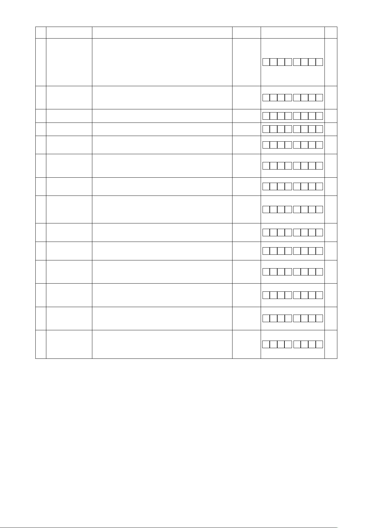
No Item Description
196 Condensation
stitching function
at the beginning of
sewing
197 The number of
condensation
stitches at the
beginning of sewing
235 Optical sensor
function
236 Optical sensor lter
function
237 Number of stitches
for the optical sensor
lter
238 Number of stitches
for stopping the
sewing machine after
optical sensor input
239 Number of times
of optical sensor
detection
242 Pedal depressing
speed limiting
function
247 Optical sensor
thread-trimming
prohibiting function
251 Optical sensor input
logic changeover
252 Correction of reverse
stitching ON at start
(when the number of
stitches is set to one)
253 Correction of reverse
stitching OFF at start
(when the number of
stitches is set to one)
254 Correction of reverse
stitching OFF at end
(when the number of
stitches is set to one)
273 Enable/disable
setting during lift of
presser foot
This function is enabled by combining with the machine head
provided with condensation stitching for shorter-thread remaining
thread trimmer.
Condensation stitching is performed at the beginning of sewing.
0 : Condensation stitching is not carried out
1 : Condensation stitching is carried out
2 : Condensation stitching is carried out when the reverse feed
stitching for the beginning of sewing is disabled. Condensa-
tion stitching is not carried out when it is enabled.
The number of condensation stitches to be sewn at the beginning
of sewing 0 to 19
Uses the optical sensor function
Sets enable/disable of the optical sensor lter function (used in
combination with No. 237)
Sets the number of stitches for ltering the optical sensor input
Sets the number of stitches to be sewn from the optical sensor
input to the stop of the sewing machine 0 to 99
The sewing machine stops every time the optical sensor input is
turned ON and carries out automatic thread trimming when the
set number is reached.
0 : The function is disabled.
1 : Fixed at the one-shot speed
2 : Limited to the one-shot speed
3 : When the optical sensor is enabled, the sewing machine
runs under the automatic mode upon depress on the pedal.
0 : Thread trimming is enabled
1 : Thread trimming is prohibited 0/1
Input logic of the optical sensor
0 : OR input
1 : AND input
The correction angle of the reverse stitching of ON activation,
when the reverse stitching is carried out at the beginning of sewing, is set.
This angle is used in the case A process is set to one stitch.
The correction angle of the reverse stitching of OFF release,
when the reverse stitching is carried out at the beginning of sewing, is set.
This angle is used in the case B process is set to one stitch.
The correction angle of the reverse stitching of OFF release,
when the reverse stitching is carried out at the end of sewing, is
set.
This angle is used in the case D process is set to one stitch.
This function setting number is used for changing over the status,
between enable and disable, of input for rotating the sewing machine while the presser foot is going up.
0 : Input is disabled
1 : Input is enabled
Setting
range
0 to 2
(stitches)
0/1
0/1
0 to 99
(stitches)
(stitches)
1 to 15
(times)
0 to 3
0/1
0 to 36
(10°)
0 to 36
(10°)
0 to 36
(10°)
0/1
Indication of function setting
1 9 6
1 9 7
2 3 5
2 3 6
2 3 7
2 3 8
2 3 9
2 4 2
2 4 7
2 5 1
2 5 2
2 5 3
2 5 4
2 7 3
2 7
Ref.
page
45
0
45
2
46
0
46
0
46
0
46
7
46
1
46
0
46
0
46
0
40
40
7
40
8
1
* Do not change the set values with asterisk (*) mark as they are functions for maintenance. If the standard set value set at the time of
delivery is changed, it is in danger of causing the machine to be broken or the performance to be deteriorated.
If it is necessary to change the set value, please purchase the Engineer’s Manual and follow the instructions.
– 31 –
Page 34

8. Detailed explanation of selection of functions
Selection of the soft-start function (function setting Nos. 1 and 37)
①
The needle thread may fail to interlace with the bobbin thread at the start of sewing when the stitching pitch
(stitch length) is small or a thick needle is used. To solve such problem, this function (called “soft-start”) is
used to limit the sewing speed, thereby assuring successful formation of the starting stitches.
1 1
The sewing speed limited by the soft-start function can be changed. (Function setting No. 37)
3 7 02 0
Material edge sensor function (function setting Nos. 2 to 4, 76)
②
This function is enabled when the material edge sensor is installed on the sewing machine.
Refer to "III-17. How to connect the material edge sensor" p.53 for details.
(Caution) This function is rendered effective only with the CP-18.
Bobbin thread counting function (function setting No. 6)
③
When the control panel is used, the function subtracts from the predetermined value and indicates the used
amount of bobbin thread.
For the details, refer to the instruction manual for the control panel.
6 1
(Caution) If “0” is set, the LCD indication on the control panel will go out and the bobbin thread count-
ing function will be invalid.
0 : The function is not selected.
1 to 9 : The number of stitches to be sewn under the soft-start mode.
Data setting range
100 to MAX sti/min < 10 sti/min >
(The MAX value varies with the machine head.)
0 : Bobbin thread counting function is not operative.
1 : Bobbin thread counting function is operative.
Thread trimming prohibiting function (function setting No. 9)
④
This function turns OFF thread trimming solenoid output when thread trimming is actuated.
(Caution) This function is rendered effective only with the CP-18.
By this function, separate sewing material can be spliced and sewn without trimming thread.
0 : OFF Thread trimming is operative. (Thread can be trimmed.)
9 0
Setting of the needle bar stop position when the sewing machine stops (function setting No. 10)
⑤
1 : ON Thread trimming is inoperative. (Thread can not be trimmed.)
The position of the needle bar when the pedal is in its neutral position is specied.
1 0 0
0 : Down The needle bar stops in the lowest position of its stroke.
1 : Up The needle bar stops in the highest position of its stroke.
(Caution) If the stop position of the needle bar is set to the highest position, the thread trimming action
will be taken after the needle bar comes down once to the lowest position.
Panel operating sound (function setting No. 11)
⑥
Whether the panel operation generates sound or not can be selected.
1 1 1
0 : OFF Operation conrmation sound is not generated
1 : ON Operation conrmation sound is generated.
– 32 –
Page 35
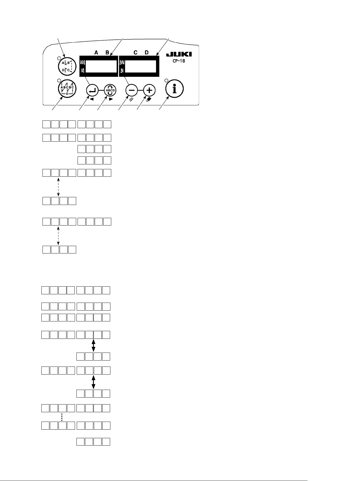
Selection of the optional input/output function (function setting No. 12)
⑦
❶
ⒷⒶ
❷
1 2 TPo _
❺❹❸
❻
Select function setting No. 12 with the operating procedure of function set-
❼
ting procedures 1) through 3).
TP _ nE_ do
Select the items of "End", "in" and "oUT" with keys ❺ and ❻.
_ni _
TUo _
0i 1 ** *
3i 2
0o 1 ** *
3o 2
*
Example) Setting the thread trimming function for the display No. i01 (CN44-4) of the input func-
[When "in" is selected]
The input function setting connector display number is displayed on indicator Ⓐ. Specify the
display number with key ❸ or ❹. Specify the connector pin function corresponding to the
displayed number by means of key ❺ or ❻. Function code and abbreviation are displayed
alternately on indicator Ⓑ. In the case "- - - -" is displayed, the function code and the abbre-
viation are automatically determined according to the selected machine head. (Refer to the
appendix for the relation between display numbers and connector pins assignment.)
[When "oUT" is selected]
The output function setting connector display number is displayed on indicator Ⓐ. Specify
the display number with key ❸ or ❹. Specify the connector pin function corresponding to
the displayed number by means of key ❺ or ❻. Function code and abbreviation are dis-
played alternately on indicator Ⓑ. In the case "- - - -" is displayed, the function code and the
abbreviation are automatically determined according to the selected machine head. (Refer
to the appendix for the relation between display numbers and connector pins assignment.)
tion setting connector.
1 2 TPo _
TPo _
0i 1 on P
0i 1 ST W
Lighting alternately
L 4
0i 1
L 4
H 4
0i 2 on P
TPo _
_ni _
i n
nE d
1. Select function setting No. 12 with the operating procedure of function
setting procedures 1) through 3).
2. Select the item of "in" with keys
3. Select i01 with key
❹
.
4. Select the thread trimming function, "TSW" with keys
5. Determine the thread trimming function, "TSW" with key
6. Set ACTIVE of the signal with keys
and ❻.
❺
❺
and ❻.
and ❻.
❺
❹
.
Set the display to "L" when the signal is "Low" and performing thread
trimming, and set the display to "H" when the signal is "High" and per-
forming thread trimming.
7. Determine the aforementioned function with key
8. Finish the optional input with key
9. Select the item of "End" with keys
.
❹
and ❻ to return to the function set-
❺
❹
.
ting mode.
– 33 –
Page 36

Input function list
Function
code
10 LinH Function of prohibiting de-
11 TinH Function of prohibiting thread
12 LSSW Low speed command input This function works as low speed switch for standing sewing ma-
13 HSSW High speed command input This function works as high speed switch for standing sewing ma-
14 USW Needle lifting function UP stop motion is performed when switch is pressed during DOWN
15 bT Reverse feed stitching switch
16 SoFT Soft start switch input The speed of stitch is limited to the predetermined soft-start speed
17 oSSW One-shot speed command
18 bKoS Backward one-shot speed
19 SFSW Safety switch input Rotation is prohibited.
20 - - -
21 AUbT Automatic reverse feed
22 CUnT Sewing counter input
23 rSW Reverse-rotation needle-up
24 vErT Alternate up/down amount
25 vSW Alternate up/down amount
26 2PiT 2-pitch alternate input 2-pitch output is inverted every time the switch is pressed
27 2PSW 2-pitch momentary switch
Abbre-
viation
0 noP No function (Standard setting)
1 HS Needle up / down compen-
sating stitching
2 bHS Back compensating stitching Reverse feed stitching is performed at low speed while the switch is
3 EbT Function of canceling once
reverse feed stitching at the
end of sewing
4 TSW Thread trimming function This function is actuated as the thread trimming switch.
5 FL Presser foot lifting function This function is actuated as the foot lifter switch.
6 oHS One stitch compensating
stitching
7 SEbT Function of cancel of reverse
feed stitching at start/end
8 PnFL Presser lifting function when
pedal is neutral
9 Ed Material edge sensor input This function works as the input signal of material edge sensor.
pressing front part of pedal
trimming output
input
switch input
command switch input
stitching cancellation/addition
switch
function
conversion panel switch input
conversion knee switch input
input
Function item Remarks
Every time the switch is pressed, normal feed stitching by half stitch
is performed. (Same operation as that of up / down compensating
stitching switch on the panel.)
held pressing. (It is effective only when a constant-dimension sewing
is selected.)
By depressing the back part of the pedal after pressing the switch,
operation of reverse feed stitching is canceled once.
Every time the switch is pressed, one stitch stitching operation is
executed.
By operating the optional switch, ineffective/effective can be alternately changed over.
Every time the switch is pressed, the function whether automatically
lifting the presser foot when the pedal is neutral or not can be selected.
Rotation by pedal is prohibited.
Output of thread trimming is prohibited.
chine.
chine.
stop.
Reverse feed stitching is output as long as the switch is held
pressed.
as long as the switch is held pressed.
This function works as one-shot speed command as long as the
switch is pressed.
Reverse feed stitching is performed in accordance with the one-shot
speed command as long as the switch is held pressed.
Every time the switch is pressed, reverse feed stitching at sewing
start or reverse feed stitching at sewing end is cancelled or added.
Every time the switch is pressed, the sewing counter value is increased.
When the switch is pressed while the sewing machine is at rest with
its needle up, the machine rotates in reverse direction and brakes
to stop at the specied angle. When the switch is pressed while the
sewing machine is at rest with its needle down, the machine rotates
in normal direction and brakes to stop at the specied angle.
Alternate up/down conversion output is inverted every time the
switch is pressed.
Alternate up/down conversion is output as long as the switch is held
pressed
2-pitch is output as long as the switch is held pressed
– 34 –
Page 37

Function
code
28 bbCG Bobbin replacement switch
29 - - -
30 TCSW Thread grasping switch input Thread grasping function is enabled as long as the switch is held
31 ALFL Presser lifter alternate switch
32 CAbT S/EBT 1-time cancellation
33 SToP Stop switch input The sewing machine is stopped and the operation is prohibited as
34 bCGP Bobbin replacement P-switch
35 Tiin Tsw command prohibition
36 USTP Lsw command prohibition/
37 Abin Reverse-feed sewing prohib-
38 FSTP Forced stop switch input Immediately brings the sewing machine into the forced stop state
39 CUSr Custom-output reset input Clears custom outputs 1 to 3
40 LGTS Optical sensor input Operates as the input signal of the optical sensor
41 CTrS Counter reset Fullls the same function as the counter reset switch on the opera-
42 rbob General-purpose remain-
43 TL2 Tension changeover switch
44 ALTC Thread grasping alternate
45 TrMd Thread trimming prohibition
46 bTP Fastening stitch alignment
47 FLTL Presser lifter and thread
48 - -
49 - - -
50 SSTL Tension release changeover
51 SrCd Condensation stitching at the
Abbreviation
Function item Remarks
input
input
input
input
input
needle-up stop input
iting function
ing-amount detection input
input
input
input
changeover input
release interlock changeover
input
inputfor condensation stitching with thread trimming
beginning of sewing change-
over input
Startup of the sewing machine is disabled when the switch is turned
ON for the rst time. (Bobbin replacement) The presser foot is lowered and the normal operation is restored when the switch is turned
ON for the second time.
pressed.
Presser lifter output is inverted every time the switch is pressed.
Reverse feed stitching at the beginning or end of sewing, to be performed after a press on the switch, is cancelled once.
long as the switch is held pressed.
When the switch is turned ON for the rst time, the sewing machine
stops with its needle up, then presser foot goes up and the startup of the sewing machine is disabled. (Bobbin replacement) The
presser foot is lowered and the normal operation is restored when
the switch is turned ON for the second time.
Thread trimming command is prohibited.
Sewing by means of the pedal switch is prohibited.
The sewing machine stops with its needle up during sewing.
Prohibits reverse-feed sewing at the beginning/end of sewing as long
as the switch is held pressed
and prohibits from performing sewing when the switch is pressed
tion panel
Works as the input signal of the bobbin-thread remaining amount
detection sensor
Changes over the thread release state on one side every time the
switch is pressed
Changes over enable/disable of the thread grasping function every
time the switch is pressed
Every time the switch is pressed, the thread trimming prohibition
status is changed over between ON and OFF.
Changes over the status of the fastening stitch alignment between
ON and OFF (Same as the enable/disable changeover of function
setting No. 151)
Changes over the status of the presser lifter and thread release interlock function between ON and OFF
(Same as the enable/disable changeover of function setting No. 194)
-
This Function setting number is used for changing over the tension
releasing function for condensation stitching with thread trimming
between ON/OFF.
(Same as the changeover between operation/no-operation of Function setting No. 186)
This function number is used for changing over the condensation
stitching function at the beginning of sewing between ON/OFF.
(Equivalent to the changeover between 0/1 of function setting No.
196)
– 35 –
Page 38

Output function list
Function
code
10 CooL Needle cooler output Output for needle cooler
11 bUZ
12 LSWo Revolution command output Revolution demanding command state is output.
13 vErT Alternate up/down amount conversion (moni-
14 2PiT 2-pitch output 2-pitch signal is output.
15 bCGo Bobbin replacement monitor output Sewing machine start-up prohibition state during
16 TC Thread grasping enabled state monitor out-
17 CAbT S/EBT 1-time cancellation monitor output One-time cancellation state of the reverse feed
18 SToP Stop state monitor output Sewing machine operation prohibition state is output.
19 AEbo Thread remaining amount detecting device
20 UdET Upper position output Output of needle-up position state
21 ddET Lower position output Output of needle-down position state
22 UPWo Upper position travel state output Monitor output while the needle goes up to its upper
23 HAWo Needle up/down correction operation output Monitor output while the needle up/down correction
24 TSWo Tsw command monitor output Thread trimming command status is output.
25 CUS1 Custom output 1 output Refer to the Engineer's Manual for details.
26 CUS2 Custom output 2 output
27 CUS3 Custom output 3 output Refer to the Engineer's Manual for details.
28 THLD Thread clamp output Output of the thread clamp at the beginning of
29 TL2 Tension increasing state monitor output Monitor output of the OFF state of the thread release
30 TrMd Thread trimming prohibition status monitor
31 bTP Fastening stitch alignment status monitor
32 FLTL Presser lifter and thread release interlock
33 - - -
34 - - -
35 - - -
36 SSTL Monitor output of tension release status for
37 SrCd Monitor output of condensation stitching sta-
Abbre-
viation
0 noP
1 TrM
2 - - -
3 TL Thread release output Output of thread release signal
4 FL Presser lifter output Output of presser lifting signal
5 bT Reverse feed stitching output Output of reverse feed stitching signal
6 EbT EBT cancel monitor output
7 SEbT
8 AUbT
9 SSTA Sewing machine stop state output Sewing machine stop state is output.
No function (Standard setting)
Thread trimming output Output of thread trimming signal
Reverse feed stitching at start/end cancel
monitor output
Sewing start/end cancellation/addition monitor output
Buzzer output
tor) output
put
air-blow output
output
output
status monitor output
condensation stitching with thread trimming
tus at the beginning of sewing
Function item Remarks
State of one time cancel of reverse feed stitching at
end function is output.
State of cancel of reverse feed stitching at start/end
is output.
State of cancel or addition of automatic reverse feed
stitching is output.
It is output when the bobbin counter set value has
been exceeded, an error has occurred or the bobbin
thread remaining amount is detected.
Alternate up/down amount conversion signal is output.
bobbin replacement is output.
Thread grasping enabled state is output.
stitching at the beginning or end of sewing is output.
Air blow output when the thread remaining amount
detecting device is used.
position.
operation is being carried out.
Refer to the Engineer's Manual for details.
sewing which is used in combination with the optical
sensor
function
Monitor output of the thread trimming prohibition
status
Monitor output of the fastening stitch alignment status
Monitor output of the presser lifter and thread release
interlock status
Output for monitoring the status of tension release for
condensation stitching with thread trimming
Output for monitoring the status of condensation
stitching at the beginning of sewing
– 36 –
Page 39

Input function setting connectors Output function setting connector
Con-
nector
No.
CN44
CN58
CN51
CN39
CN36
Pin
Display
No.
No.
4 i01 Machine head switch 1 input
5 i02 Machine head switch 2 input
6 i03 Machine head switch 3 input
7 i04 Machine head switch 4 input
8 i05 Machine head switch 5 input
9 i06 Machine head switch 6 input
10 i07 Machine head switch 7 input
11 i08 Machine head switch 8 input
15 i09 Option 1 input
16 i10 Option 2 input
17 i11 Option 3 input
18 i12 Option 4 input
19 i13 Option 5 input
20 i14 Option 6 input
21 i15 Option 7 input
22 i16 Option 8 input
4 i17 Option 9 input
5 i18 Option 10 input
6 i19 Option 11 input
7 i20 Option 12 input
8 i21 Option 13 input
9 i22 Option 14 input
10 i23 Option 15 input
11 i24 Option 16 input
7 i25 TSW (thread trimming switch input)
11 i26 LSSW (low speed switch)
9 i27 HSSW (high speed switch)
5 i28 FL (presser lifter switch input)
4 i31 FL (presser lifter switch input)
5 i32 bT (reverse feed stitching switch input)
Initial value of function setting
Con-
nector
No.
CN44
CN59
CN51
Pin
Display
No.
15 o01 Machine head LED 1 output
16 o02 Machine head LED 2 output
17 o03 Machine head LED 3 output
18 o04 Machine head LED 4 output
19 o05 Machine head LED 5 output
20 o06 Machine head LED 6 output
21 o07 Machine head LED 7 output
22 o08 Machine head LED 8 output
11 o09 Option 1 output
12 o10 Option 2 output
13 o11 Option 3 output
14 o12 Option 4 output
15 o13 Option 5 output
16 o14 Option 6 output
17 o15 Option 7 output
18 o16 Option 8 output
19 o17 Option 9 output
20 o18 Option 10 output
21 o19 Option 11 output
22 o20 Option 12 output
23 o21 Option 13 output
24 o22 Option 14 output
25 o23 Option 15 output
26 o24 Option 16 output
15 o25 Option 17 output
16 o26 Option 18 output
17 o27 Option 19 output
18 o28 Option 20 output
19 o29 Option 21 output
Initial value of function setting
No.
– 37 –
Page 40
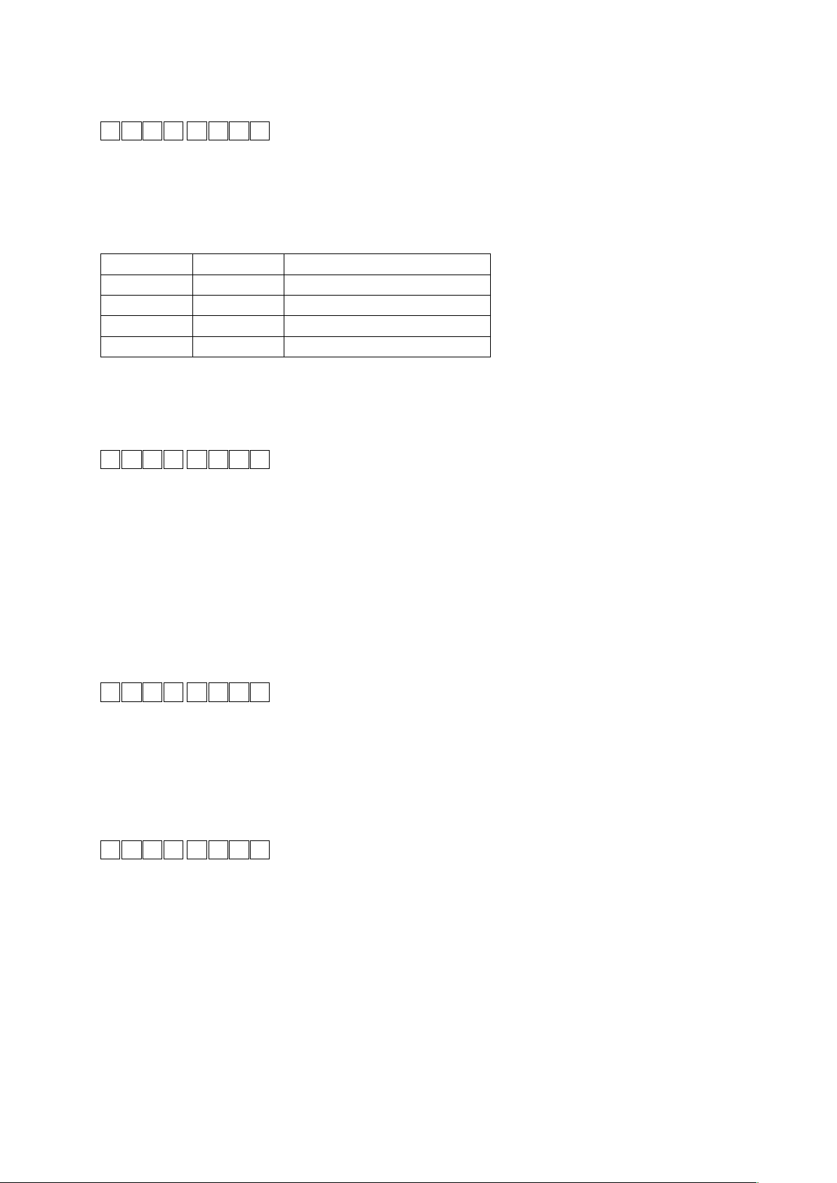
Sewing counting function (function setting No. 14)
⑧
The function counts up every time thread trimming is completed and counts the number of completion of the
sewing process.
1 4 1
0 : OFF Sewing counting function is inoperative.
1 : ON Sewing counting function is operative. (Every time thread trim-
ming is performed)
2 : ON External sewing counter switch input.
(Caution) The sewing counter can only be operative when the CP-180 is used with the sewing machine.
The counter indication changes as shown below according to the combination of setting No. 6 and setting
No. 14.
Setting No. 6 Setting No. 14 Counter
1 1 Bobbin counter
1 0 Bobbin counter
0 1 Sewing counter (only with CP-180)
0 0 Counter function is ineffective.
Neutral automatic presser lifting function (function setting Nos. 21 and 155)
⑨
This function can automatically lift the presser foot when the pedal is in the neutral position.
(Caution) This function is disabled when No. 93 Needle up/down switch additional function setting is "3"
Function of automatic presser foot lifting at neutral position of pedal (function setting No. 21)
0 : Not provided with the function of automatic presser foot lifting at neutral
2 1 0
position of pedal
1 : Provided with selectable function of automatic presser foot lifting at neu-
tral position of pedal
2 : Provided with the function of automatic presser foot lifting at neutral po-
sition of pedal when enabled and added with the function of conducting
alternate operation by depressing the back part of pedal
(Caution) The alternate function is carried out regardless of the set-
ting of No. 155.
Setting of the position of carrying out automatic presser foot lifting at neutral position of pedal (function set-
ting No. 155)
51 5
0 : The function of automatic presser foot lifting at neutral position of pedal
0
is enabled at all times
1 : The automatic presser foot lifting at neutral position of pedal is only en-
abled when the sewing machine stops with its needle down
Needle up/down switch function changeover function (function setting No. 22)
⑩
The needle up/down switch function can be changed over between the needle up/down compensation and
one stitch compensation.
2 2 0
0 : Needle up / down compensating stitching
1 : One stitch compensating stitching
– 38 –
Page 41

Function of reverse feed stitching on the way (function setting Nos. 30 to 33)
⑪
Functions of the limit of number of stitches and thread trimming command can be added to the touch back
switch on the sewing machine head.
Function setting No. 30 Function of reverse feed stitching on the way is selected.
0 : OFF Normal back-tack function
3 0 0
1 : ON Function of reverse feed stitching on the way
Function setting No. 31 Number of stitches performing reverse feed stitching is set.
Setting range : 0 to 19 stitches
3 1 4
Function setting No. 32 Effective condition of reverse feed stitching on the way
3 2 0
0 : OFF
Inoperative when the sewing machine stops. (Reverse feed stitch-
ing on the way functions only when the sewing machine is running.)
1 : ON Operative when the sewing machine stops.
(Reverse feed stitching on the way functions both when the sew-
ing machine is running and stops.)
(Caution)
Either condition is operative when the sewing machine is running.
Function setting No. 33 Thread trimming is performed when reverse feed stitching on the way is completed.
0 : OFF Without thread trimming
3 3 0
1 : ON Thread trimming is executed.
Application
❶
❷
❸
❹
❺
Function setting
No. 30 No. 32 No. 33
0 0 or 1 0 or 1 It works as normal touch-back switch.
1 0 0
1 1 0
1 0 1
1 1 1
When operating touch-back switch at the time of depressing front part of the pedal,
reverse feed stitching as many as the number of stitches specied by the function
setting No. 31 can be performed.
When operating touch-back switch at the time of either stop of the sewing machine or
depressing front part of the pedal, reverse feed stitching as many as the number of
stitches specied by the function setting No. 31 can be performed.
When operating touch-back switch at the time of depressing front part of the pedal,
automatic thread trimming is performed after reverse feed stitching as many as the
number of stitches specied by the function setting No. 31 has been performed.
When operating touch-back switch at the time of either stop of the sewing machine
or depressing front part of the pedal, automatic thread trimming is performed after
reverse feed stitching as many as the number of stitches specied by the function
setting No. 31 has been performed.
Output function
Actions under each setting state
Used as the normal reverse feed stitching touch-back switch.
❶
Used for reinforcing seam (press sewing) of the pleats. (It works only when the sewing machine is running.)
❷
Used for reinforcing seam (press sewing) of the pleats.
❸
(It works either when the sewing machine stops or when the sewing machine is running.)
Used as starting switch for reverse feed stitching at the sewing end.
❹
(Used as the substitute for thread trimming by depressing back part of the pedal. It works only when the sewing
machine is running. It is especially effective when the sewing machine is used as the standing-work machine.)
Used as starting switch for reverse feed stitching at the sewing end.
❺
(Used as the substitute for thread trimming by depressing back part of the pedal. It works either when the sewing
machine stops or when the sewing machine is running. It is especially effective when the sewing machine is used
as the standing-work machine.)
Number of rotation of one-shot stitching (function setting No. 38)
⑫
This function can set, by the pedal operation of one time, the sewing speed of one-shot stitching when the sewing machine continues stitching until completing the number of stitches specied or detecting the material end.
Setting range : 150 to MAX sti/min < 50 sti/min >
3 8 051 0
(Caution) The max. number of rotation of one-shot stitching is limited by the model of the sewing machine head.
– 39 –
Page 42
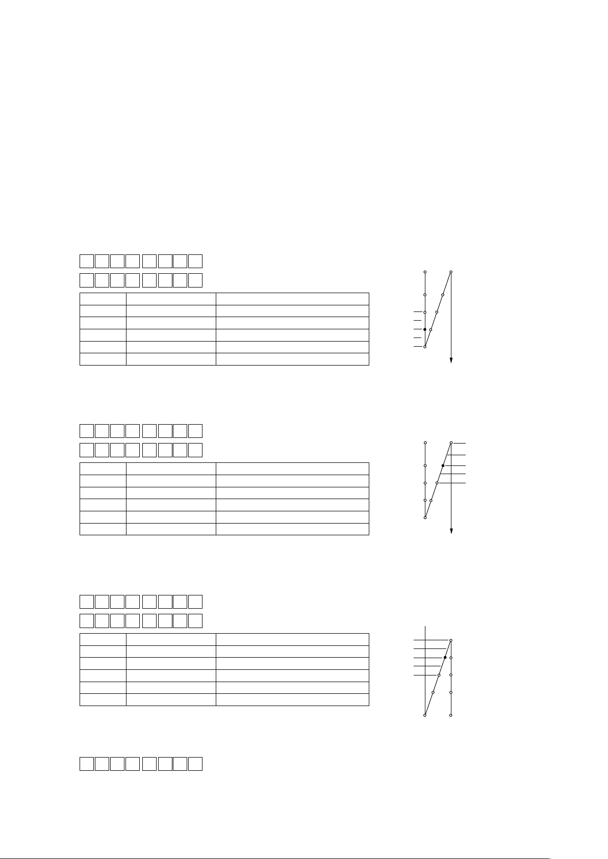
Reverse-feed stitching timing correction (function setting Nos. 51 to 53, 252 to 254)
⑬
This function is used for changing the ON/OFF timing of output of reverse feed stitching for correction in
the case stitches sewn with the forward feed stitching and those sewn with the reverse feed stitching do not
match under the automatic reverse feed stitching.
(Caution) 1. These functions are enabled when the function setting No. 151 Fastening stitch alignment
is set to OFF.
2. In the case the timing of the solenoid cannot be corrected with ease due to a large stitching
pitch, it is recommended to reduce the number of revolutions of reverse feed stitching (No. 8).
3. Also refer "III-11. Stitch alignment for the reverse stitching at the end of sewing (for heavy-
weight materials)" p.48 for the procedure for correcting the ON timing of the reverse
stitching solenoid at the end of sewing.
Compensation of ON-timing or reverse feed stitching at the start of sewing (function setting Nos. 51
❶
and 252)
ON-timing for reverse feed stitching at the start of sewing can be compensated by the unit of angle.
No. 252 is used in the case the number of stitches of A process is set to one stitch.
5 1 2 7
2
5 2 2 7
Set value Compensation angle Number of stitches of compensation
–36 –360° –1
–18 –180° –0.5
0 0° 0
18 180° 0.5
36 360° 1
Compensation of OFF-timing for reverse feed stitching at the start of sewing (function setting Nos. 52
❷
Adjusting range : – 36 to 36 < 1 / 10˚ >
Adjusting range : 0 to 36 < 1 / 10˚ >
–360˚
–180˚
180˚
360˚
* Set the angle with
reference to the
needle entry point
of the previous
stitch.
0˚
and 253)
OFF-timing for reverse feed stitching at the start of sewing can be compensated by the unit of angle.
No. 253 is used in the case the number of stitches of B process is set to one stitch.
5 2 7
2
5 3 7
Set value Compensation angle Number of stitches of compensation
–36 –360° –1
–18 –180° –0.5
0 0° 0
18 180° 0.5
36 360° 1
Compensation of OFF-timing for reverse feed stitching at the end of sewing (function setting Nos. 53
❸
Adjusting range : – 36 to 36 < 1 / 10˚ >
Adjusting range : 0 to 36 < 1 / 10˚ >
360˚
180˚
0˚
–180˚
–360˚
and 254)
OFF-timing for reverse feed stitching at the start of sewing can be compensated by the unit of angle.
No. 254 is used in the case the number of stitches of D process is set to one stitch.
5 3 8
Adjusting range : – 36 to 36 < 1 / 10˚ >
2
5 4 8
Set value Compensation angle Number of stitches of compensation
–36 –360° –1
–18 –180° –0.5
0 0° 0
18 180° 0.5
36 360° 1
Foot lift function after thread trimming (function setting No. 55)
⑭
Adjusting range : 0 to 36 < 1 / 10˚ >
360˚
180˚
0˚
–180˚
–360˚
This function can automatically lift the presser foot after thread trimming.
5 5 1
0 : OFF Function of automatically lifting the presser foot is not provided.
(Presser foot does not automatically go up after thread trimming.)
1 : ON Function of automatically lifting the presser foot is provided.
(Presser foot automatically goes up after thread trimming.)
– 40 –
Page 43

Reverse revolution to lift the needle after thread trimming (function setting No. 56)
⑮
This function is used to make the sewing machine rotate in the reverse direction after thread trimming to lift
the needle bar almost to highest position. Use this function when the needle appears under the presser foot
and it is likely to make scratches on the sewing products of heavy-weight material or the like.
5 6 1
0 : OFF Function of making the sewing machine rotate in the reverse di-
rection to lift the needle after thread trimming is not provided.
1 : ON Function of making the sewing machine rotate in the reverse di-
rection to lift the needle after thread trimming is provided.
(Caution) The needle bar is raised, by rotating the machine in the reverse direction, almost to the high-
est dead point. This may result in slip-off of the needle thread. It is therefore necessary to
adjust the length of thread remaining after thread trimming properly.
Needle bar home position retaining function (function setting Nos. 58, 61 and 179)
⑯
When the needle bar is in its specied position, it is retained at that position by applying a gentle brake.
Needle bar home position retaining function (function setting No. 58)
5 8 1
0 : OFF Needle bar home position retaining is disabled
1 : ON
2 : ON
3 : ON
Needle bar home position retaining is enabled (holding force is weak.)
Needle bar home position retaining is enabled (holding force is medium.)
Needle bar home position retaining is enabled (holding force is strong.)
Needle bar home position retaining time (function setting No. 61)
This function automatically cancels the function No. 58 after the lapse of the set time when the latter is in the
ON state.
This function should be used when you want to turn the sewing machine pulley after the completion of sewing.
6 1 0
0 : Function is disabled The needle bar home position retaining is ena-
bled at all times.
100 - 3000 ms < 100 ms >
Time limit for needle bar home position retaining (function setting No. 179)
The time limit for retention of the needle bar at its home position is set.
7 9 31
0 : The function is disabled (no limit)
1 to 10 min
Change-over function of AUTO / Pedal for sewing speed of the reverse feed stitching at the start of
⑰
sewing (function setting No. 59)
This function selects whether the reverse feed stitching at the start of sewing is performed without a break at
the speed set by the function setting No. 8 or the stitching is performed at the speed by the pedal operation.
5 9 1
0 : Manual The speed is indicated by the pedal operation.
1 : Auto Automatic stitching at the specied speed
(Caution) 1. The max. sewing speed of the reverse feed stitching at the start of sewing is limited to the
speed set by the function setting No. 8 regardless of the pedal.
2. When “0” is selected, stitches of reverse feed stitching may not match those of normal feed
stitching.
Function of stop immediately after the reverse feed stitching at the start of sewing (function set-
⑱
ting No. 60)
This function temporarily stops the sewing machine even when keeping depressing the front part of the pedal
at the time of completion of process of reverse feed stitching at the start of sewing.
It is used when sewing a short length by reverse feed stitching at the start of sewing.
6 0 0
0 : Not provided with the function of temporary stop of the
sewing machine immediately after the reverse feed
stitching at the start of sewing
1 : Provided with the function of temporary stop of the sew-
Stop the sewing machine
temporarily to change
direction of sewing
products.
ing machine immediately after the reverse feed stitching
at the start of sewing
– 41 –
Page 44
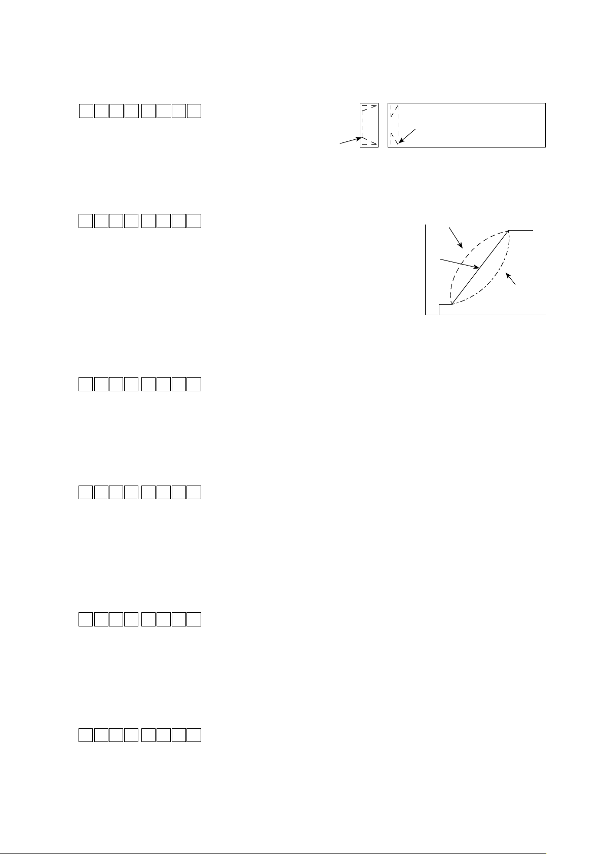
Function of reducing speed of reverse feed stitching at the start of sewing (function setting No. 92)
⑲
Function to reduce speed at the time of completion of reverse feed stitching at the start of sewing : Normal
use depending on the pedal condition (Speed is accelerated to the highest without a break.)
This function is used when temporary stop is used properly. (Cuff and cuff attaching)
9 2 0
1 : Speed is reduced.
Function of pedal curve selection (function setting No. 87)
⑳
0 : Speed is not reduced.
Temporary stop
Sew without stopping
without a break.
This function can perform the selection of the curve of number of rotation of the sewing machine against the
depressing amount of the pedal.
Change to this function when you feel that inching operation is hard or that pedal response is slow.
8 7 0
0 : Number of rotation of the sewing
1 to 10
machine in terms of the depressing
amount of the pedal increases linearly.
– 1 to – 10 : Reaction to intermediate speed in
0
terms of the depressing amount of
the pedal is delayed.
1 to 10 : Reaction to intermediate speed in
terms of the depressing amount of
the pedal is advanced.
(sti/min)
Number of rotation
– 1 to – 10
Pedal stroke (mm)
Initial motion UP stop position move function (function setting No. 90)
Effective/ineffective of automatic return to UP stop position immediately after turning ON the power can be set.
0 :
9 0 2
The function is disabled. (Find the origin by keeping depressing the front
part of the pedal)
1 : Needle-up stop position at the time of startup.
2 : Reverse-rotation needle-up stop position at the time of startup.
Function added to the needle up / down compensating switch (function setting No. 93)
Operation of needle up/down compensating switch is changed after turning ON the power or thread trimming.
9 3 0
0 : Normal (needle up/down compensating stitching only)
1 : One stitch compensating stitching is performed only when aforemen-
tioned changeover is made. (Upper stop → upper stop)
2 : Needle-down function operates after thread trimming.
3 : Function of needle-down with operation of 2 plus presser lowering op-
eration and needle-up with thread trimming operation is added.
Sewing machine startup selecting function (function setting No. 72)
Current limit at the startup of sewing machine is specied.
7 2 32 7
0 : No limit to the start-up acceleration
1 to 250 : Restricted amount of the start-up acceleration
Continuous stitching + one shot stitching nonstop function (function setting No. 94)
This function is used to proceed a step to the next one without stopping the sewing machine at the end of the
step when performing sewing with the continuous sewing and one-shot sewing combined using the programming function of the operation panel IT.
9 4 0
0 : Normal (Stop when a step has completed.)
1 : The sewing machine proceeds to next step without stopping after a
step has completed.
– 42 –
Page 45

Setting of max. number of rotation of the sewing machine head (function setting No. 96)
This function can set the max. number of rotation of the sewing machine head you desire to use.
Upper limit of the set value varies in accordance with the sewing machine head to be connected.
9 6 083 0
Main shaft reference angle compensation (function setting No. 120)
Main shaft reference angle is compensated
21 0 0
UP position starting angle compensation (function setting No. 121)
Angle to detect UP position starting is compensated.
21 1 0
DOWN position starting angle compensation (function setting No. 122)
Angle to detect DOWN position starting is compensated.
21 2 0
Setting of energy saving function during standby (function setting No. 124, 128)
It is possible to reduce power consumption while the sewing machine is in standby state. It should be noted
that the startup of the sewing machine may delay for a moment if this function is set.
Setting of energy saving function during standby (function setting No. 124)
21 4 0
1 : Energy-saving mode is effective.
Energy-saving mode changeover time (function setting No. 128)
This function is used for setting the time to be elapsed from the start of standby-state until the operation
mode is changed over to the energy-saving mode.
21 8 0
150 to Max sti/min < 50 sti/min >
Setting range : – 60 to 60˚ < 1˚ >
Setting range : – 15 to 15˚ < 1˚ >
Setting range : – 15 to 15˚ < 1˚ >
0 : Energy-saving mode is ineffective.
Setting range : 0 to 60 < ms >
Number of stitches setting for automatic cancellation of alternate up/down output (function setting
No. 144)
Alternate up/down output is cancelled when the set number of stitches has been sewn (0: Automatic cancellation is disabled). After the alternate up/down output is output by the set number of stitches, output is turned
OFF. When "0" is set, this function does not work. (However, the number of stitches actually sewn may be
larger than the set one according to the sewing speed.)
41 4 0
1 to 30 stitches
Selection of alternate up/down output after thread trimming (function setting No. 146)
Alternate up/down output is forcibly turned ON or OFF after thread trimming.
When this function is set to disable, the alternate up/down output retains the state before thread trimming.
When the set value is "1," the alternate up/down output is brought into the OFF state. When the set value is
"2," the output is brought into the ON state.
41 6 0
1 : OFF
2 : ON
Selection of alternate up/down initial output (function setting No. 147)
Alternate up/down output is forcibly turned ON or OFF when the power is turned ON.
When this function is set to disable, the alternate up/down output is restored to the state in which the function
has been set before the last turn-OFF of the power.
When the set value is "1," the alternate up/down output is brought into the OFF state. When the set value is
"2," the output is brought into the ON state.
41 7 0
1 : OFF
2 : ON
0 : Automatic cancellation is disabled
0 : Disabled
0 : Disabled
– 43 –
Page 46

2-pitch output during reverse feed stitching at the beginning/end of sewing (function setting No.
148)
2-pitch output is set in the ON state during control of reverse feed stitching at the beginning/end of sewing.
41 8 0
0 : The function is in the OFF state
1 : The function is in the ON state
2-pitch output inversion during alternate up/down output (function setting No. 149)
The 2-pitch output status is output with inverted in synchronism with the alternate up/down output.
2-pitch output is changed over to "OFF" if it is set in the ON state or to "ON" if it is set in the OFF state when
changing over the alternate up/down output.
41 9 0
0: The function is in the OFF state
1: The function is in the ON state
2-pitch initial output selection (function setting No. 150)
2-pitch output is forcibly turned ON or OFF when the power is turned ON.
When this function is set to disable, the 2-pitch output is restored to the state in which the function has been
set before the last turn-OFF of the power.
When the set value is "1," the alternate up/down output is brought into the OFF state. When the set value is
"2," the output is brought into the ON state.
51 0 0
0 : Disabled
1 : OFF
2 : ON
Pause and stitch alignment function (function setting No. 151)
When the reverse feed stitching/multi-layer stitching is specied, the sewing machine temporarily stops at
every corner of the sewing pattern at the beginning and end of sewing and during overlapped stitching.
(Caution) When this function is brought into ON state, functions setting Nos. 51 to 53 are disabled.
51 1 0
0 : The function is in the OFF state
1 : The function is in the ON state
Temporarily
stops at these
points.
Condensation stitching function for beginning/end of sewing (function setting No. 154)
In the case of the sewing machine head provided with the condensation stitching function, the sewing machine performs condensation stitching instead of automatic reverse feed stitching.
This function should be used when you do not want to carry out reverse feed stitching but want to prevent
thread from slipping off the material at the beginning and end of sewing.
51 4 0
0 : The function is in the OFF state
1 : The function is in the ON state
Needle thread grasping function (function setting No. 156)
Selection between enable/disable of the needle thread grasping function
51 6 0
0 : Enable/disable is changed over with the operation enabling switch
1 : The function is disabled
2 : The function is enabled.
Bobbin thread remaining amount detecting function (function setting Nos. 167 and 168)
Enable/disable of the bobbin thread remaining amount detecting function (function setting No. 167)
Enable/disable of the bobbin thread remaining amount detecting function is set in the case the bobbin thread
remaining amount detecting device is used.
61 7 0
0 : Disabled
1 : Enabled
Bobbin thread remaining amount detecting function (function setting No. 168)
Refer to the Instruction Manual for the device for details about the setting.
61 8 0
– 44 –
Page 47
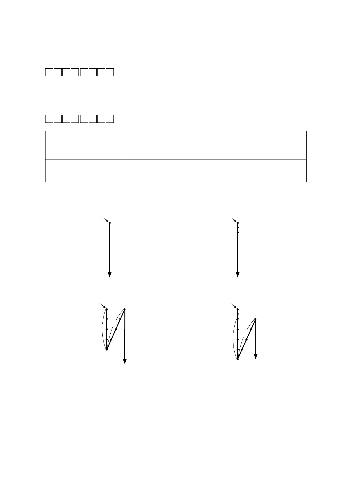
Condensation stitching function at the beginning of sewing (function setting Nos. 196 and 197)
Conditions under which the condensation stitching function for the beginning of sewing is enabled/disabled
are specied. Unraveling and skipping of stitches can be prevented by carrying out condensation stitching at
the beginning of sewing.
Function setting No. 196 Condensation stitching function at the beginning of sewing
0: The function is disabled
91 6 0
1: The function is enabled
2: The function is enabled when the reverse feed stitching at the be-
ginning of sewing is disabled. The function is disabled when the
reverse feed stitching at the beginning of sewing is enabled.
Function setting No. 197 The number of condensation stitches at the beginning of sewing
Setting range: 0 to 19 stitches (Initial value: 2 stitches)
91 7 2
In the case the reverse feed
stitching for the beginning of sewing is not carried out (Example 1)
In the case the reverse feed
stitching for the beginning of sewing is carried out (Example 2)
When the number of reverse feed stitches is set at 0 (zero), the condensation
stitching function for the beginning of sewing does not work at the beginning
of sewing. When it is set at 1 or 2, the condensation stitching function for the
beginning of sewing works.
When the number of reverse feed stitches is set at 0 (zero) or 2, the condensation stitching function does not work at the beginning of sewing. When it is
set at 1, the condensation stitching function for the beginning of sewing works.
(Example 1) In the case the reverse feed stitching function for the beginning of sewing is disabled:
(Set value: 0)
Sewing start position
(Set value: 1 or 2)
Sewing start position
Condensation
stitching
{
(Example 2) In the case the reverse feed stitching function for the beginning of sewing is enabled:
(Set value: 0 or 2) (Set value: 1)
Sewing start position
Sewing start position
Condensation
B
A
stitching
{
B
A
In the case the reverse feed stitching function for the beginning of sewing is enabled, the sewing start
and end positions are not aligned if the set value is 1 (Set value: 1).
In order to align them, change the setting as described below:
• Set the condensation stitching function for the beginning of sewing at 0 (zero) (Set value: 0).
• Taking the number of stitches set by the function setting No. 197 into account, reduce the number of
reverse feed stitches at the beginning of sewing in the zone A or increase it in the zone B.
– 45 –
Page 48

Optical sensor function (function setting Nos. 235 to 239, 242, 247 and 251)
Optical sensor function (function setting No. 235)
Enable this function if it is to be used.
Before enabling this function, assign the optical sensor input with No. 12.
(Caution) This function is enabled only for the CP-18. For the other operation panels, set the optical sen-
sor with the switches on the panel.
32 5 0
0 : Optical sensor function is disabled
1 : Optical sensor function is enabled
Optical sensor lter function (function setting No. 236)
This function lters the optical sensor input.
Use this function in combination with function No. 237: Number of stitches for optical sensor lter.
32 6 0
0 : Optical sensor lter function is disabled
1 : Optical sensor lter function is enabled
Numbers of stitches for optical sensor lter (function setting No. 237)
The number of stitches for which the optical sensor input is ltered is set.
It is used when function No. 236: Number of stitches for optical sensor lter is enabled.
32 7 0
Direction of sewing
0 to 99 stitches
Sensor signal
Sensor input
No. 237
Number of stitches for stopping the sewing machine after optical sensor input (function setting No. 238)
The number of stitches to be sewn from the optical sensor input to the stop of the sewing machine is set.
(Caution)
This function is enabled only for the CP-18. For the other operation panels, set the number of
stitches for stopping the sewing machine after optical sensor input with the switches on the panel.
32 8 7
0 to 99 stitches
Number of times of optical sensor detection (function setting No. 239)
The sewing machine carries out automatic thread trimming when the set number of times the optical sensor
input is turned ON is reached.
32 9 1
1 to 15 times
Pedal depressing speed limiting function (function setting No. 242)
The function limits the sewing speed upon the optical sensor input.
(Caution) This function can be set to "3" only for the CP-18. For the other operation panels, set this func-
tion with the switches on the panel.
42 2 0
0 : The function is disabled.
1 : Fixed at the one-shot speed
2 : Limited to the one-shot speed
3 : When the optical sensor is enabled, the sewing machine runs under the
automatic mode upon depress on the pedal.
Optical sensor thread-trimming prohibiting function (function setting No. 247)
Thread trimming activated by the optical sensor input is prohibited.
(Caution) This function can be set only for the CP-18. For the other operation panels, set this function with
the switches on the panel.
42 7 0
0 : Thread trimming is enabled
1 : Thread trimming is disabled (solenoid output is prohibited)
Optical sensor input logic changeover (function setting No. 251)
In the case two or more optical sensors are used, the input retrieving method is selected.
52 1 0
0 : OR input
1 : AND input
– 46 –
Page 49

9. Automatic compensation of neutral point of the pedal sensor
Whenever the pedal sensor, spring, etc. are replaced, be sure to perform following operation :
❶
ⒷⒶ
1) Pressing switch
, turn ON the
❹
power switch.
2) Compensated value is displayed on
indicator Ⓑ.
(Caution) 1. At this time, the pedal sen-
sor does not work properly
if the pedal is depressed.
Warning sound "blips" and
the correct compensation
❷
❻❺❹❸
❼
value is not displayed.
2. If any display ("-0-" or "-8-
") other than a numeric
value appears on indicator
, refer to the Engineer's
Ⓑ
Manual.
3) Turn OFF the power switch, and turn ON the power switch again to return to the normal mode.
(Caution) Be sure to re-turn ON the power switch when one or more seconds have passed after turning it
OFF. (If the ON-OFF operation is carried out faster than the above, the setting may not change
normally.)
10.Selectionofthepedalspecications
When the pedal sensor has been replaced, change the set value of function setting No. 50 according to the
newly connected pedal specications.
0 : KFL
1 : PFL
(Caution) Pedal sensor with two springs
located at the back part of the
pedal type is PFL, and that
with one spring type is KFL.
Set the pedal sensor to PFL
when lifting the presser foot
by depressing the back part of
the pedal.
❷
❶
ⒷⒶ
❻❺❹❸
❼
– 47 –
Page 50

11. Stitch alignment for the reverse stitching at the end of sewing (for heavy-weight materials)
Particularly in the case of the machine head for heavy-weight materials, stitches are not always aligned in
the section shown in the gure below even if the timing of the reverse feed stitching at the end of sewing is
corrected. In this case, set the following function to align the stitches.
At the timing when the sewing machine starts
①
reverse stitching, the rotating speed of the sewing
EBT section
Speed
Low speed section
①
Time
machine in the section where the sewing machine
is rotated at a low speed can now be changed.
Function setting No. 64
Standard
Machine head LU-2810ES-7 (Heavy-weight
Condition
Pitch 6 mm
Number of stitches 4 stitches
ITEM No. 64 180 sti/min
Stitch pitch is
shortened.
materials)
Misaligned
Example of setting of function No. 64
Machine head LU-2810ES-7 (Heavy-weight
Condition
Pitch 6 mm
Number of stitches 4 stitches
ITEM No. 64 0 sti/min
materials)
– 48 –
Page 51

12. Input/output function of the hand switch and knee switch
❶
ⒷⒶ
❽
ThegureofhandswitchofLU-2810ES-7
is shown above.
❷
❻❺❹❸
❼
For the sewing machine head which is provided with the hand switch or the knee switch, the input/output
function of the switch can be set by pressing the switch during function setting operation.
At this time, the input/output function of the hand switch and the input function of the knee switch can be
changed.
Refer to “III-8. ⑦ Input function list” p.34 and “III-8. ⑦ Output function list” p.36 for the selectable
functions.
A press on the switch enables the input function setting. One more press on the switch enables the output
function setting.
It must be remembered, however, that output function of the switch which is not provided with the output LED
cannot be set.
* Example) To assign the thread trimming function to the BT switch
9 6 083 0
3i 2 b T
3i 2 ST W
Lighting alternately
3i 2 4
1. Turn ON the power switch with switch
2. Press BT switch
3. Press switch
❺
and
❽
.
switch
❻
function.
4. Press switch
❸
and
switch
❹
function.
held pressed.
❼
to display "TSW" thread trimming
to conrm "TSW" thread trimming
– 49 –
Page 52
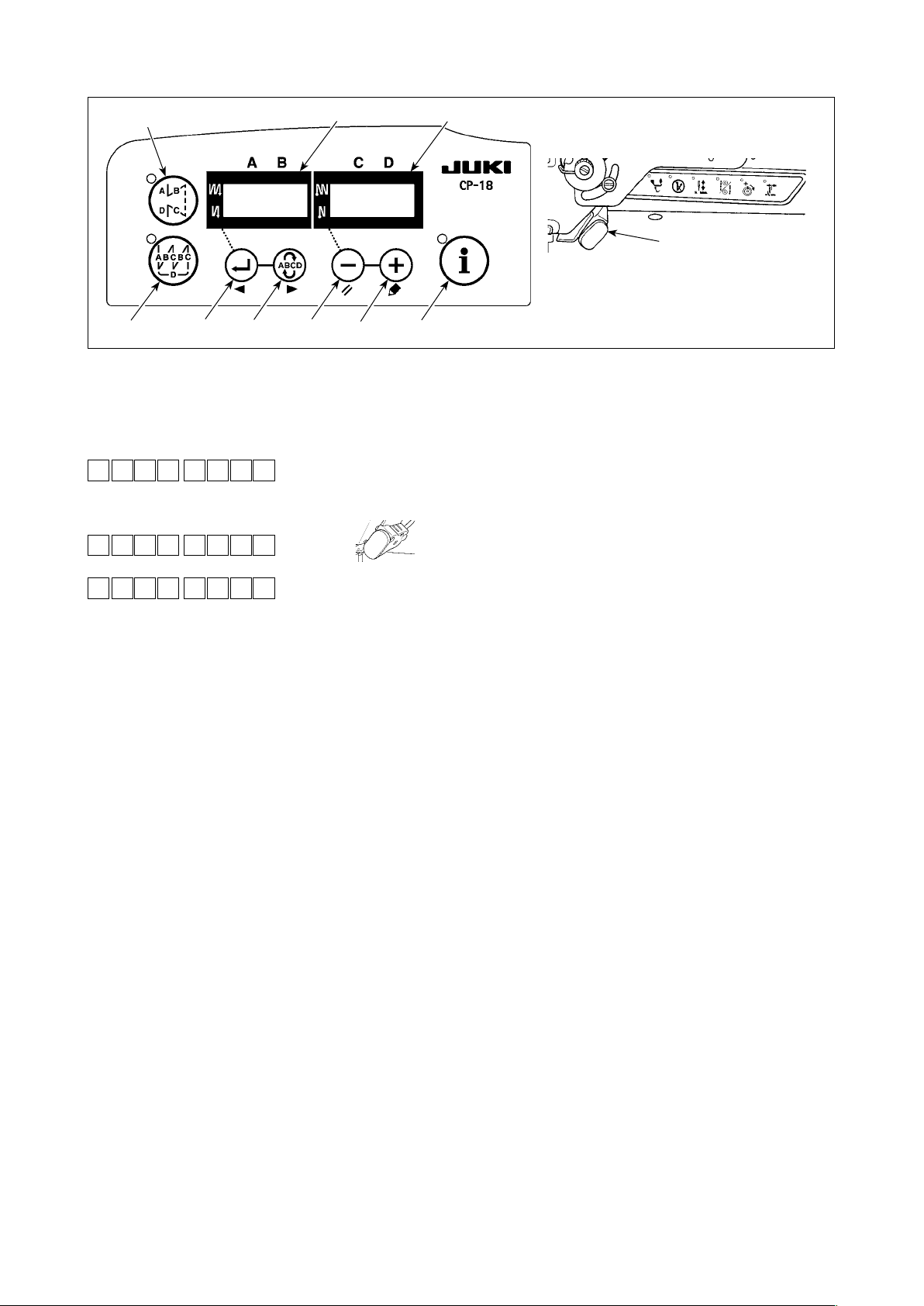
13. Use of the hand switch and the knee switch
❼
ⒷⒶ
❽
ThegureofhandswitchofLU-2810ES-7
is shown above.
"III-4. One-touch
to display "bT oFF".
❽
❶
❷
For the sewing machine head which is provided with the hand switch or the knee switch, enable/disable of
the switch can be selected by pressing the switch during one-touch setting.
* Example) Disabling the BT switch
MAL P o n
b T Fo F
1. Bring the SC-923 into the setting mode referring to
2. Press BT switch
❻❺❹❸
setting" p.19.
MAL P o n
3. Automatically a second later or a press on one of switches
display returns to the previous state.
to ❼, the
❶
– 50 –
Page 53

14. Selecting procedure of the key-lock function
Setting of the number of stitches for a pattern can be prohibited by enabling the key lock function.
❶
ⒷⒶ
1) Turn ON the power switch with
switch ❺ and switch
❻
held
pressed.
2) “KEY LOCK” is displayed on indica-
tors Ⓐ and Ⓑ with a blip to make the
key-lock function effective.
3) The panel returns to the normal oper-
ation after displaying “KEY LOCK” on
❷
❻❺❹❸
❼
the indicators.
4) While the key lock function is effective, “KEY LOCK” is displayed on the indicators when turning the power
ON.
5) When you carry out steps 1) to 3) in repetition, “KEY LOCK” is not displayed when turning the power ON
and the key lock function is rendered ineffective.
• “KEY LOCK” display when turning the power ON
Display appears : The key lock function is effective.
Display does not appear : The key lock function is ineffective.
15. Initialization of the setting data
All contents of function setting of SC-923 can be returned to the standard set values.
❶
❷
(Caution) Do not turn OFF the power on the way of initializing operation. Program of the main unit may be
broken.
❻❺❹❸
ⒷⒶ
❼
4) Turn OFF the power switch and turn ON the power switch after closing the front cover. The machine re-
turns to the normal motion.
(Caution) 1. When you carry out the aforementioned operation, the neutral position correction value for
the pedal sensor is also initialized. It is therefore necessary to carry out automatic correction
of the pedal sensor neutral position before using the sewing machine. (Refer “III-9. Automatic
compensation of neutral point of the pedal sensor” p.47.)
2. When you carry out the aforementioned operation, the machine-head adjustment values are
also initialized. It is therefore necessary to carry out adjustment of the machine head before
using the sewing machine. (Refer “II-5. Adjusting the machine head” p.14.)
3. Even when this operation is performed, the sewing data set by the operation panel cannot be
initialized.
1) Turn ON the POWER switch with
all of switch
and
switch
2) "rS" is displayed on indicator
,
❹
held pressed.
❻
switch
Ⓑ
with
a blip to start initialization.
3) The buzzer sounds after approxi-
mately one second (single sound
three times, “peep”, “peep”, and
“peep”), and the setting data returns
to the standard setting value.
❺
– 51 –
Page 54

16. External input / output connector
A switchable general-purpose input/output is provided at function setting No. 12 for an external output con-
nector ❶ (CN51).
(Caution) When using the connector, note that the engineer who has the electrical knowledge has to work.
❶
Table of assignment of connector and signal
CN51 Signal name No. 12 display No. Input/output Description Electric spec.
1 GND GND
2 GND GND
3 MA Output Rotation signal 360 pulses/rotation DC5V
4 OPI9 i17 Input Option 9 input DC3.3V
5 OPI10 i18 Input Option 10 input DC3.3V
6 OPI11 i19 Input Option 11 input DC3.3V
7 OPI12 i20 Input Option 12 input DC3.3V
8 OPI13 i21 Input Option 13 input DC3.3V
9 OPI14 i22 Input Option 14 input DC3.3V
10 OPI15 i23 Input Option 15 input DC3.3V
11 OPI16 i24 Input Option 16 input DC3.3V
12 +24V Power source
13 +24V Power source
14 +5V Power source
15 OPO17 o25 Output Option 17 output NPN open collector
16 OPO18 o26 Output Option 18 output NPN open collector
17 OPO19 o27 Output Option 19 output NPN open collector
18 OPO20 o28 Output Option 20 output NPN open collector
19 OPO21 o29 Output Option 21 output NPN open collector
20 N.C. Unconnected
21 N.C. Unconnected
22 N.C. Unconnected
[JUKI genuine part No.] • Connector ......Part No. : HK034610220
• Pin contact .....Part No. : HK03464000A
– 52 –
Page 55

17. How to connect the material edge sensor
For SC-923, a commercially available photoelectric sensor can be connected and used as a material end
sensor.
A connection example is shown below.
Pin No. Signal Remarks
2 GND 0V
11 OPI16 Sensor input
13 +24V Power source
(CN51)
❷
(Cable band)
❸
2-wire
system
3-wire
system
❶
1) Connect the material end sensor to the connector
(Molex, 22P).
❶
For 2-wire system, connect 0 V and the sensor
input to pin 2 and pin 11, respectively.
For 3-wire system, connect 0 V, the sensor input,
and 24 V to pin 2, pin 11, and pin 13, respective-
ly.
2) Insert the connector
that was connected in the
❶
step 1 into the connector ❷ (CN51, 22P) of SC-
923.
3) Pass these cables through the cable clamp and
fasten them with the cord of the material end
sensor with the cable band ❸ mounted on the
side face of the box.
4) Connect CN51-11 (display No. i24) to the ma-
terial edge sensor input referring to “III-8. ⑦
Selection of the optional input/output function
(function setting No. 12)” p.33.
(Caution) 1. Be sure to turn OFF the power before
connection.
2. Use a 24 V-ready material end sensor.
3. Refer to
p.19
edge sensor.
"III-4. One-touch setting"
for how to use the material
– 53 –
Page 56

IV. MAINTENANCE
1. Removing the rear cover
WARNING :
To prevent personal injuries caused by electric shock hazards or abrupt start of the sewing machine,
remove the cover after turning OFF the power switch and a lapse of 5 minutes or more. To prevent
personal injuries, when a fuse has blown out, be sure to replace it with a new one with the same
capacity after turning OFF the power switch and removing the cause of the blown-out of the fuse.
1) Press the OFF button of the power switch to turn
OFF the power after conrming that the sewing
machine has stopped.
2) Draw out the power cord coming from the power
plug socket after conrming that the power switch
is turned OFF. Perform the work of step 3) after
conrming that the power has been cut and it has
passed for 5 minutes or more.
❷
3) Loosen setscrew
in cover ❶. Open cover ❶.
❷
❶
❸
4) To close cover
paying attention to the orientation of cable clip
band ❸ mounted on the side face of the box.
, re-tighten setscrew ❷ while
❶
2. Replacing the fuse
(1) PWR PCB
(Caution) The illustration below shows the PWR-T PCB. The type of PCB differs by destination.
1) Remove all the cables
which are connected to
the control box.
2) Remove the connecting
rod.
3) Remove the control box
❶
from the table stand.
❷
4) Holding the glass sec-
tion of fuse ❶, remove
the fuse.
(Caution) There is a risk of electrical shock when removing the fuse. Be sure to remove the fuse after LED
has totally gone out.
❷
5) Be sure to use a fuse with the designated capacity.
: 3.15 A/250 V Time-lag fuse (Power circuit protective fuse)
❶
Part number: KF000000080
6) Install the control box on the table stand. (Refer to
7) Connect all the cables to the control box. (Refer to
8) Fit the connecting rod back in place. (Refer to
“II. SET-UP” p.1.)
“II-2. Connecting the cords” p.4.)
“II-3. Attaching the connecting rod” p.12.)
– 54 –
Page 57

(2) CTL PCB
❸
(Caution) There is a risk of electrical shock when removing the fuse. Be sure to remove the fuse after LED
has totally gone out.
❷
1) Open the cover of the control box.
2) Pick up the glass section of fuse
(Caution) In order to protect against the possibility of electric shock, it is necessary to remove the fuse
after LED ❷ of the PWR PCB has totally gone off.
3) Be sure to use a fuse with the designated capacity.
: 3.15 A/250 V Time-lag fuse (Solenoid power circuit protection fuse)
❸
Part number: KF000000030
4) Close the cover of the control box.
mounted on the CTL PCB with ngers to remove it.
❸
– 55 –
Page 58

3. Error codes
In case of the following, check again before you judge the case as trouble.
Phenomenon Cause Corrective measure
When tilting the sewing machine,
the buzzer beeps and the sewing
machine cannot be operated.
Solenoids for thread trimming
Solenoids for thread trimming,
reverse feed, etc. fail to work. Hand
lamp does not light up.
Even when depressing the pedal
immediately after turning ON the
power, the sewing machine does not
run. When depressing the pedal after
depressing the back part of pedal
once, the sewing machine runs.
The sewing machine does not stop
even when the pedal is returned to
its neutral position.
Stop position of the sewing machine
varies (irregular).
Presser foot does not go up even
when auto-lifter device is attached.
Touch-back switch fails to work. Presser foot is going up by auto-liter
UP position move fails to work when
all lamps on the panel light up.
Sewing machine fails to run. Motor output cord (4P) is disconnect-
When tilting the sewing machine
without turning OFF the power
switch, Action given on the left side is
taken for safety sake.
When the fuse for solenoid power
protection has blown out
Neutral position of the pedal has
varied.
(Neutral position may be shifted
when changing spring pressure of
the pedal or the like.)
When tightening the screw in the
handwheel is forgotten at the time of
adjustment of needle stop position.
Auto-lifter function is OFF. Select “FL ON” by auto-lifter function
Pedal system is set to KFL system. Change the jumper to PFL setting to
Cord of auto-lifter device is not con-
nected to connector (CN37).
device.
Auto-lifter device is not attached.
However, auto-lifter function is ON.
The mode is in the function setting
mode.
The switch on the CTL PCB is
pressed by the bound cords and the
aforementioned mode resulted.
ed.
Connector (CN30) of motor signal
cord is disconnected.
Tilt the sewing machine after turning
OFF the power.
Check the fuse for solenoid power
protection.
Execute the automatic neutral correc-
tion function of the pedal sensor.
Securely tighten the screw in the
handwheel.
selection.
lift the presser foot by depressing the
back part of the pedal.
Connect the cord properly.
Operate the switch after the presser
foot lowered.
Select “FL OFF” when auto-lifter
device is not attached.
Remove the under cover. Bundle
the cables by routing them accord-
ing to the normal routing method as
described in the Instruction Manual.
Connect the cord properly.
Connect the cord properly.
– 56 –
Page 59

In addition, there are the following error codes in this device. These error codes interlock (or limit function)
and inform the problem so that the problem is not enlarged when any problem is discovered. When you re-
quest our service, please conrm the error codes.
❶
ⒷⒶ
[Checking procedure of the error code]
1) Turn ON the power switch with
switch ❸ held pressed.
2) The latest error number is displayed
on indicator Ⓑ with a blip.
3) Contents of previous errors can be
checked by pressing switch ❸ or
❷
(Caution) When switch
❻❺❹❸
is pressed, the previous error
❸
❼
switch
❹
.
(When the conrmation of the con-
tents of previous error advanced to
code of the currently displayed one is displayed.
When
switch
is pressed, the next error code
❹
the last, the warning sound peeps in
single tone two times.)
of the currently displayed one is displayed.
Error code list
No. Description of error detected Cause of occurrence expected Items to be checked
− Media cover open
E000 Execution of data initialization
(This is not the error.)
E007 Overload of motor
E008 Undened machine head is
selected
E009 Solenoid energizing time over
E011(*) Media is not inserted.
E012(*) Read error • Data of media cannot be read. • Turn the power OFF and check the media.
E013(*) Write error • Data of media cannot be written. • Turn the power OFF and check the media.
E014(*) Write protect • Media is in the state of writing prohibition. • Turn the power OFF and check the media.
E015(*) Format error • Formatting cannot be performed. • Turn the power OFF and check the media.
E016(*) External media capacity over • Capacity of media is short. • Turn the power OFF and check the media.
E019(*) File size over • File is too large. • Turn the power OFF and check the media.
E032(*) File interchangeability error • There is no interchangeability of le. • Turn the power OFF and check the media.
E041(*) Sewing recorder error • This error number is displayed in the event
E044(*) Date and time error • This error number is displayed in the event
E053(*) Notication of production sup-
port function initialization (This
is not an error)
* The error number attached with an asterisk (*) is displayed only in the case a fault occurs when the IT panel is connected to
the sewing machine.
• Cover of the slot of media is open. • Close the cover.
• When the machine head is changed.
• When the initialization operation is execut-
ed
• When the machine head is locked.
• When sewing extra-heavy material beyond
the guarantee of the machine head.
• When the motor does not run.
• Motor or driver is broken.
• The machine head that does not support
the SC-923 is selected.
• The predetermined solenoid energizing
time is exceeded.
• Media is not inserted. • Turn the power OFF and check the media.
of a sewing recorder data fault.
of operation/data fault concerning date or
time of day.
• This error number is displayed after the
execution of initialization of the production
support function or upgrading of the program.
• Check whether the thread has been entangled in the motor pulley.
• Check the motor output connector (4P) for
loose connection and disconnection.
• Check whether there is any holdup when turning the motor by hand.
• Check the machine head selection using function setting No. 95.
• Check whether the machine head is locked by
the thread trimmer.
• Check whether the pulley can be turned
smoothly by hand.
• Check whether the data has any fault.
• Check whether the data has any fault.
• Check whether the data has any fault.
– 57 –
Page 60

No. Description of error detected Cause of occurrence expected Items to be checked
E055(*) Production management error
E056(*) Work management error • This error number is displayed in the event
E057(*) Pitch time monitor error • This error number is displayed in the event
E065(*) Network transmission failed • This message is displayed in the case data
E067(*) ID reading failed • This message is displayed in the case data
E071 Disconnection of motor output
connector
E072 Overload of motor at the time
of thread trimming motion
E079 Excessive power of motor • The main motor is applied with an exces-
E204(*) USB insertion
E205(*) Warning of ISS buffer remain-
ing amount
E220 Grease-up warning • When the predetermined number of stitch-
E221 Grease-up error
E302 Fall detection switch failure
(When the safety switch works)
E303 Semicircular plate sensor error
E499 Simplied program data fault
E703(*) Operation panel is connect-
ed to the unexpected sewing
machine. (Error of sewing
machine model)
E704(*) System version mismatch
E730 Encoder failure
E731 Motor hole sensor failure
* The error number attached with an asterisk (*) is displayed only in the case a fault occurs when the IT panel is connected to
the sewing machine.
• This error number is displayed in the event
of production management work management data fault.
of data fault.
of pitch time monitor data fault.
cannot be sent to the personal computer by
way of the network.
in the ID le is broken.
• Disconnection of motor connector • Check the motor output connector for loose
• Same as E007 • Same as E007
sive load.
• This message is displayed in the case the
sewing machine is activated with the USB
thumb drive inserted.
• This message is displayed in the case the
buffer storage for storing the ISS data is
almost full.
If the sewing machine is continuously used
with the buffer storage full, the stored pieces of data will be erased from the earliest
one.
es has been reached.
• When the predetermined number of stitches has been reached and the sewing is not
possible.
• When fall detection switch is input in the
state that the power is turned ON.
• Semicircular plate sensor signal cannot be
detected.
• Command parameter data is out of specied range.
• The operation panel and the sewing
machine model do not match in the initial
communication.
• The system version is different from the
correct one in the initial communication.
• When the motor signal is not properly
inputted.
• Check whether the data has any fault.
• Check whether the data has any fault.
• Check whether the data has any fault.
• Check whether the network has any fault.
• Check whether the data has any fault.
connection and disconnection.
• Check whether the pulley can be turned
smoothly by hand. (When sewing the extra
heavy-weight material thickness of which exceeds the guaranteed value for the machine
head.)
• Remove the USB thumb drive.
• Output the data.
• Replenish the specied places with grease
and reset.
(For the details, refer to the data of the ma-
chine head.)
• Replenish the specied places with grease
and reset.
(For the details, refer to the data of the ma-
chine head.)
• Check whether the machine head is tilted
without turning OFF the power switch (sewing
machine operation is prohibited for safety
sake).
• Check whether the machine head corresponds with the machine type setting.
• Check whether the motor encoder connector
is disconnected.
• Re-enter the relevant simplied program.
• Set the simplied program in disable.
• Connect the operation panel to the correct
model of the sewing machine.
• Re-write the system version to the one that
can be used with the operation panel.
• Check the motor signal connector (CN30) for
loose connection and disconnection.
• Check whether the motor signal cord has broken since the cord is caught in the machine
head.
• Check whether the inserting direction of the
motor encoder connector is wrong.
– 58 –
Page 61

No. Description of error detected Cause of occurrence expected Items to be checked
E733 Inverse rotation of motor
E799 Thread trimming operation
time-out
E808 Solenoid short circuit
E811 Abnormal voltage
E900 Motor driver overload
E902 Main shaft overcurrent
E906 Operation panel transmission
failure
E912 Main shaft out-of-control
E922 Main shaft out-of-control
E924
IPM element error
E942 Faulty EEPROM
E955
Electric current sensor error
E963 IPM temperature abnormality
E977 CPU runaway detection • In the case a program error has occurred in
* The error number attached with an asterisk (*) is displayed only in the case a fault occurs when the IT panel is connected to
the sewing machine.
• This error occurs when the motor is running
at 500 sti/min or more in the opposite
direction of that of rotation indication during
motor is running.
• The thread trimming control operation is not
completed within the predetermined time
(within three seconds).
• Solenoid power does not become normal
voltage.
• When voltage higher than guaranteed one
is inputted.
• 200V has been inputted to SC-923 of 100V
specications.
• JA : 220V is applied to 120V box.
• CE : 400V is applied to 230V box.
• When voltage lower than guaranteed one is
inputted.
• 100V has been inputted to SC-923 of 200V
specications.
• JA : 120V is applied to 220V box
• Inner circuit is broken by the applied overvoltage.
• Same as E007 • Check whether the motor can be turned
• Main motor overcurrent • Check whether the pulley hitches or has a
• Disconnection of operation panel cord
• Operation panel has broken.
• Speed abnormality • Check whether the pulley has a backlash
• Program fault • Check whether there is a source of noise in
• Motor driver overload
• Data cannot be written on the EEPROM. • Turn the power OFF.
• The electric current ows while the machine
is at rest.
• The IPM produces heat. • Check whether the IPM is securely xed.
the CPU
• Check whether the machine head corresponds with the machine type setting.
• Check whether the main-shaft motor encoder
wire is connected incorrectly.
• Check whether the main-shaft motor wire for
power supply is connected incorrectly.
• Check whether the machine head actually
installed is different from the machine head
selection.
• Check whether the machine head cord is
caught in the pulley cover or the like.
• Check whether the applied power voltage is
higher than the rated voltage + (plus) 10% or
more.
• Check whether 100V/200V changeover connector is improperly set.
In the aforementioned cases, POWER PCB is
broken.
• Check whether the voltage is lower than the
rated voltage - (minus) 10% or less.
• Check whether 100V/200V changeover connector is improperly set.
• Check whether fuse or regenerative resistance is broken.
smoothly by hand.
backlash when it is turned by hand.
• Check the operation panel connector (CN38)
for loose connection and disconnection.
• Check whether the operation panel cord has
broken since the cord is caught in the machine head.
when it is turned by hand.
the vicinity.
• Check whether the pulley hitches or has a
backlash when it is turned by hand.
• Check whether the motor can be turned
smoothly by hand.
– 59 –
 Loading...