

Page 1

ENGLISH
SC-910N
INStruCtIoN MaNuaL
i
Page 2

CONTENTS
!
. SPECIFICATIONS ..................................................................................... 1
@
. SET-UP ...................................................................................................... 1
1. Installing M91 small sized motor unit ............................................................................................... 1
2. Installing to the table ..........................................................................................................................2
3. Adjusting the belt (when M91 is used) ..............................................................................................2
4. Adjusting the belt cover (when M91 is used) ...................................................................................3
5. Connecting the cords .........................................................................................................................4
6. Attaching the connecting rod .......................................................................................................... 11
7. Setting procedure of the machine head .........................................................................................12
8. Machine head list ..............................................................................................................................13
9. Adjusting the machine head (DDL-9000A only) .............................................................................14
#
. FOR THE OPERATOR ............................................................................ 15
1. Operating procedure of SC-910N .................................................................................................... 15
2. Explanation of the operation panel .................................................................................................17
3. Operating procedure of the sewing pattern ...................................................................................18
(1) Reverse stitching pattern ..............................................................................................................18
(2) Overlapped stitching pattern ......................................................................................................... 19
(3) Special setting ..............................................................................................................................20
4. Setting for functions of SC-910N .....................................................................................................22
5. Function setting list .......................................................................................................................... 24
6. Detailed explanation of selection of functions ..............................................................................31
7. Automatic compensation of neutral point of the pedal sensor ................................................... 40
8.Selectionofthepedalspecications .............................................................................................. 40
9. Setting of the auto lifter function ....................................................................................................41
10. Connection of the pedal of standing-work machine .....................................................................41
11. External input / output connector ...................................................................................................42
12. Connection of the material end sensor (ED) ..................................................................................42
13. Initialization of the setting data ....................................................................................................... 43
$
. MAINTENANCE ...................................................................................... 44
1. Removing the rear cover .................................................................................................................. 44
2. Replacing the fuse ...........................................................................................................................44
3. Error codes ........................................................................................................................................ 45
i
Page 3
!
. SPECIFICATIONS
Supply voltage Single phase 100 to 120V 3-phase 200 to 240V Single phase 200 to 240V
Frequency 50Hz/60Hz 50Hz/60Hz 50Hz/60Hz
Operating envi-
ronment
Input 350VA 350VA 350VA
@
. SET-UP
SC-910N control box can be used for DD (direct-drive) system machine head and the belt-drive system
machine head by connecting the separately-available small-sized motor unit (M91).
When using the small-sized motor unit, it is necessary to install the motor unit to the control box before in-
stalling the control box to the table.
Install the motor unit to the control box following the instructions below.
Temperature : 0 to 40˚C
Humidity : 90% or less
Temperature : 0 to 40˚C
Humidity : 90% or less
Temperature : 0 to 40˚C
Humidity : 90% or less
ENGLISH
SC-910N control box
A
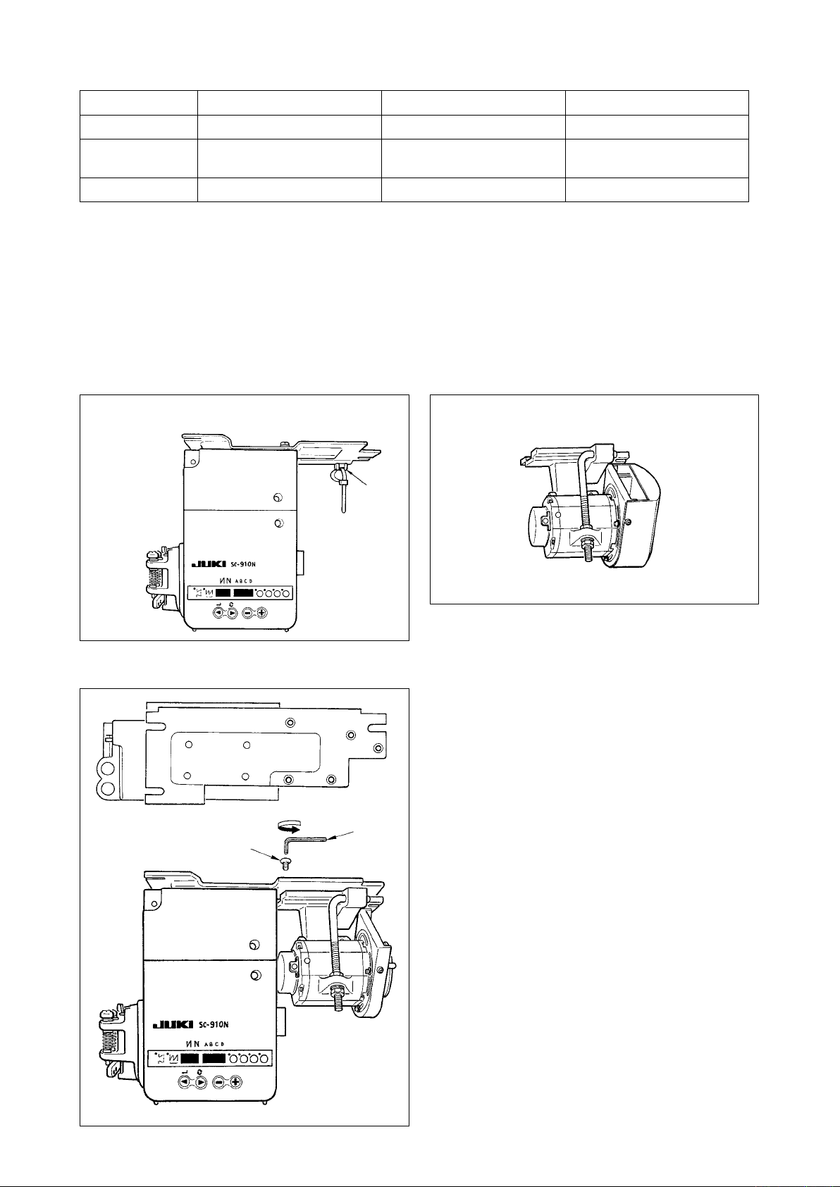
1. Installing M91 small sized motor unit
2
1
M91 small-sized motor unit (separately-available article)
1) Lay down the control box while the rear cover is
placed under the control box.
2) Remove tie-mount A.
3) Adjust the hole section of the installing base of
M91 to the hole section of the installing plate.
4) Temporarily tighten ve places with counter-sunk
screws 1 supplied with the unit as accessories.
5) Securely tighten them with hexagonal wrench
key
(Caution) 1. W h e n tighten i n g t he screw, se-
2. Hexagonal wrench key is attached
3. Be careful that the motor shaft does
supplied with the unit as accessories.
2
curely insert the hexagonal wrench
key into the screw hole section to
tighten.
to M91.
not hit against anything. (If a strong
shock is given to the motor shaft,
there is the possibility that the mo-
tor is damaged.)
– 1 –
Page 4
2. Installing to the table
Plain washer
Spring washer
Hexagonal nat
1) Install the control box to the table with the tting
bolt (asm.) supplied with the unit as accessories.
At this time, insert the nut and washer supplied
with the unit as accessories as shown in the gure so that the control box is securely xed.
2) Set the machine head to the table after installing the control box (or with small-sized motor) to the
table. (Refer to Instruction Manual for the sewing machine.)
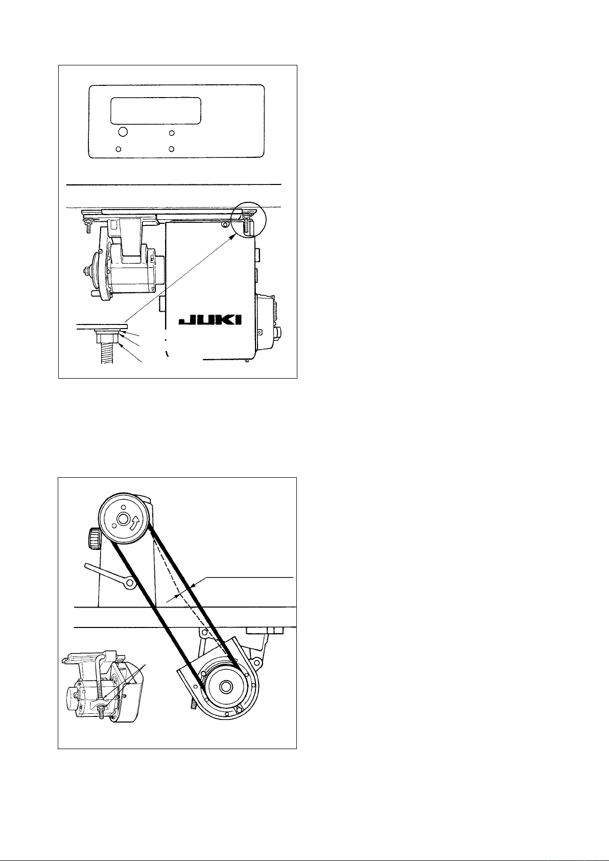
3. Adjusting the belt (when M91 is used)
1) Adjust the belt tension by turning upper and lower
nuts 1of the adjustment bolt and adjusting the
height of the center of the motor so that the belt
sags 15 mm (9.8N) when the center of the belt is
pressed by hand.
(Caution) 1. When the belt tensi o n i s exces-
Approx. 15mm / 9.8N
1
sively low, medium or low speed
rotation becomes uneven, or stop
accuracy is deteriorated. When the
tension is excessively high, dete-
rioration of the motor is advanced.
So, be careful.
– 2 –
Page 5
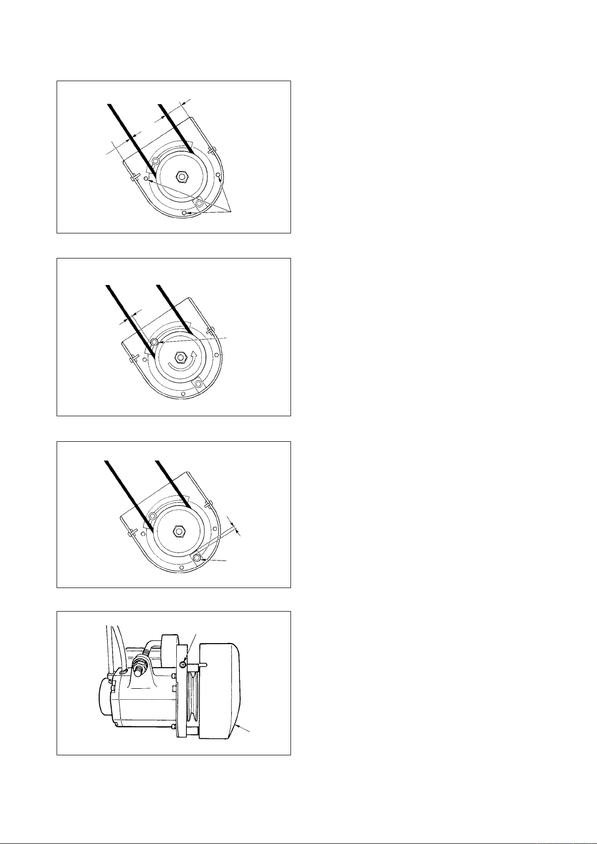
4. Adjusting the belt cover (when M91 is used)
1) Adjusting the clearance of the cover
Loosen cover setscrew 1 and adjust so that the
left and right clearances between the belt cover
and the belt are equal to each other.
(Caution) 1. Perform the adjustment of the cov-
1
2) Adjusting the roll-in prevention pin
Adjust the roll-in prevention pin with the hexago-
nal wrench key supplied with the unit as acces-
sories so that the clearance between the belt and
roll-in prevention pin 2 is approximately 4 mm.
4mm
2
3mm
3
5
(Caution) 1. Be careful of the direction of rota-
2. Perform the adjustment of the cov-
3) Adjusting the off-belt prevention pin
Adjust the off-belt prevention pin with the hexag-
onal wrench key supplied with the unit as acces-
sories so that the clearance between the belt and
off-belt prevention pin 3 is approximately 3 mm.
(Caution) 1. Perform the adjustment of the cov-
4) Installing the belt cover
Adjust the notch section of the pulley outer cover
4
er and insert the outer cover to the inner cover.
er with the hexagonal wrench key
supplied with the unit as accesso-
ries. At this time, be careful that the
screw is not excessively loosened.
ENGLISH
tion of the motor and determine the
position of the pin. (Position shown
in the figure is the installing posi-
tion when the motor rotates in the
direction of the arrow mark.)
er with the hexagonal wrench key
supplied with the unit as accesso-
ries. At this time, be careful that the
screw is not excessively loosened.
er with the hexagonal wrench key
supplied with the unit as accesso-
ries. At this time, be careful that the
screw is not excessively loosened.
to the gap of screw 5 of the pulley inner cov-
4
5) Tighten screw 5 to complete the adjustment of
the cover.
– 3 –
Page 6
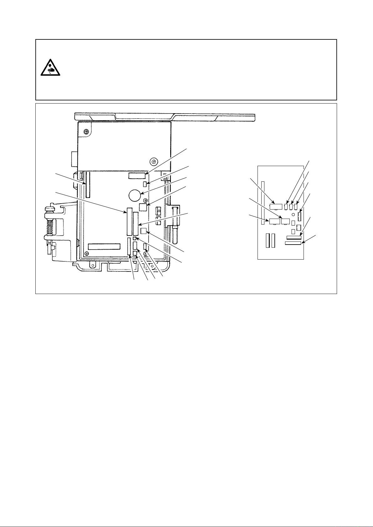
5. Connecting the cords
WARNING :
• To prevent personal injury caused by abrupt start of the sewing machine, carry out the work after
turning OFF the power switch and a lapse of 5 minutes or more.
• To prevent damage of device caused by maloperation and wrong specifications, be sure to
connectallthecorrespondingconnectorstothespeciedplaces.
• To prevent personal injury caused by maloperation, be sure to lock the connector with lock.
• As for the details of handling respective devices, read carefully the Instruction Manuals supplied
with the devices before handling the devices.
7
3
4
5
8
1
6
Optional unit A
2
9
!1
2
1
9
6
7
8
5
!3
3
!2
!0
4
Following connectors are prepared on the front face of SC-910N. Connect the connectors coming from the
machine head to the corresponding places so as to t the devices mounted on the machine head.
CN30 Synchronizer : it detects the needle bar
1
position.
CN35 CP-170 panel : Various kinds of
2
programmed sewing can be executed.
(Refer to the Instruction Manual for each
panel for the details of functions.)
CN31 Machine head connector 4P
3
CN42 External input/output connector : input/
4
output of up/down detection signal, rotation
prohibition signal, etc. is prepared.
CN48 Safety switch (standard) : When tilting the
5
sewing machine without turning the power
OFF, the operation of the sewing machine is
prohibited so as to protect against danger.
Optional switch : by changing over the
internal functions, 6 kinds of functions can
be selected.
CN40 Presser foot lifter solenoid. (For automatic
6
presser foot lifter type only)
CN46
7
CN47 Optional circuit board connection connector
8
Machine head solenid : Thread trimming, reverse-
stitching solenoid, touch-back switch, etc.
: Required when using JUKI standard
bobbin thread remaining amount detection
sensor, etc.
CN39 Motor signal connector
9
CN32 Standing machine pedal : JUKI standard
!0
PK-70, etc. Sewing machine can be
controlled with the external signal.
CN34 IP-110 panel (LCD panel) : Various kinds of
!1
programmed sewing can be executed.
CN45 Material end detection sensor ED-5, etc.
!2
CN43 Fan
!3
* By adding the optional unit A, the following optional
devices of JUKI standard can be connected.
CN128 Left/right needle detection
1
CN127 Thread holding, thread suction, thread
2
drawing
CN122 Needle cooler (bottom fan)
3
CN121 Bobbin thread remaining amount detection
4
CN120 +24V external power source
5
CN123 Needle/bobbin thread remaining amount
6
detection sensor
CN125 External interface I/F D/A Input
7
CN126 Left/right lock SW, LED
8
CN129 Thread holding, thread suction, thread
9
drawing, bobbin thread remaining amount
detection.
– 4 –
Page 7
7
2
3
A
5
6
1
4
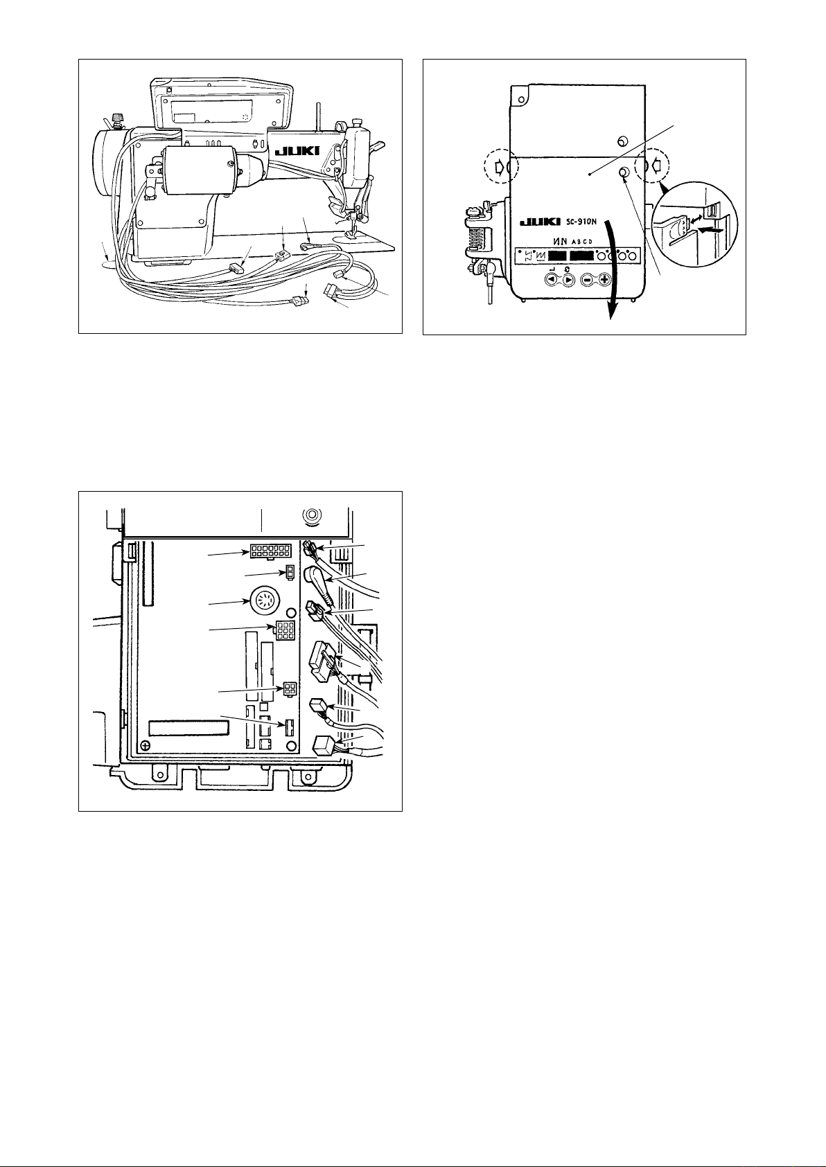
1) P a s s th e co rd s 1 o f t he t h r e a d t ri m m i ng
solenoid, reverse-stitching solenoid, etc., and
the cords of the synchronizer 2, safety switch
, machine head 4P connector 4, motor signal
3
, motor output 6 through hole A in the table to
5
route them down under the machine table.
A
F
D
E
C
B
9
2
3
1
4
5
8
2) Loosen setscrew 8 in front cover 7.
3) Pressing the side of front cover 7 in the direction
of the arrow, open the front cover toward you.
Note : Be sure to open / close the front cover
with your hands.
4) Connect 14P code 1 coming from the machine
head to connector A (CN46).
5) Connect 4P connector coming from the machine
head 4 to connector B (CN31). (It is not necessary in case of DDL-9000A.)
6) Connect 4P connector 3 (safty switch connector) coming from the machine head to connector
(CN48).
C
7) Connect 7P connector 2 coming from the ma-
chine head to connector D (CN30).(It is not nec-
essary in case of DDL-9000A.)
8) Connect connector 5 coming from the machine
head (motor) to connector E (CN39).
9) When the optional AK138 device is attached,
connect 2P connector 9 coming from the AK device to connector F (CN40).
ENGLISH
(Caution) 1.
WhenusingtheAKdevice,setwhethertousetheAK device after conrming how to
select the auto-lifter function. (Refter to “#-9. Setting of the auto lifter function” p. 41.)
2. Be sure to securely insert the respective connectors after checking the inserting di-
rections since all connectors have the inserting directions. (When using a type with
lock, insert the connectors until they go to the lock.) The sewing machine is not actuated unless the connectors are inserted properly. In addition, not only the problem
of error warning or the like occurs, but also the sewing machine and the control box
are damaged.
– 5 –
Page 8
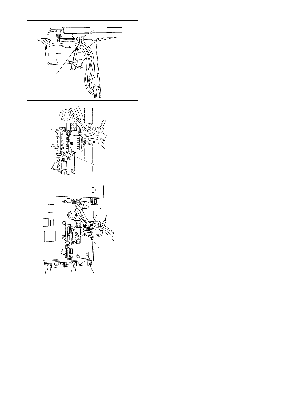
10) Fix all cables coming from the machine head
!0
!1
with cable clip band !0 attached to tie-mount !1.
[ Connection of the connector for CP panel ]
Exclusive connectors are prepared for connection of
the connector for CP-170.
C
Paying attention to the orientation of the connec-
tor, connect it to connector B located on the circuit
board. After connecting, securely lock the connector.
[ Connecting for IP panel ]
The connector for connecting IP-110 is prepared.
B
When connecting, insert the connector until it is
locked to C.
!4
!3
!2
11) After inserting the connector, put all cords to-
gether with cable clip band !2 located on the side
of the box.
At this time, bundle the connectors which are
arranged above the wire saddle to wire saddle
and those which are arranged below the wire
!3
saddle to wire saddle !4.
(Caution) 1. Fix the cord clamp and the cable
clip band following the attaching
procedure.
2. When removing the connector, re-
move it from the wire saddle and
remove it while pressing the hook
of the cable clip band.
– 6 –
Page 9
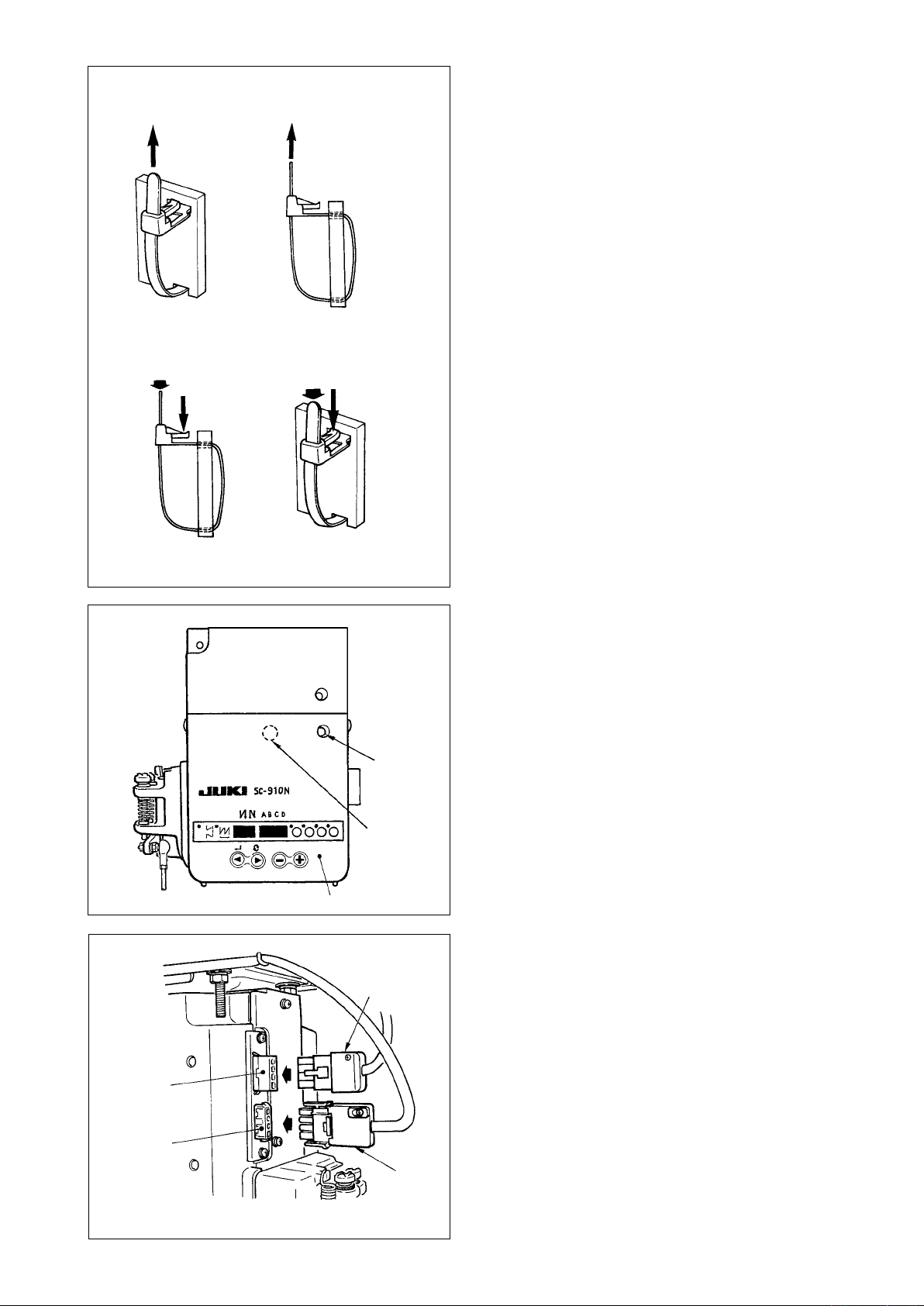
Howtoxcableclipband
Pull
!2
Pull
(Caution) 1. Fix the cable clip band following
the attaching procedure as shown
inthegure.
2. To r emov e the c able c lip b a n d,
pu sh the c able clip band u ntil it
comes off while pressing the hook
of the band following the removing
procedureasshowninthegure.
How to remove cable clip band
Push
Pushing the hook portion, push the band to remove it.
Push
Push the hook.
8
12) Close front cover 7 while paying attention to
pinching of the wire.
Lightly press portion D and insert front cover
7
with “click”.
13) After that, x it with the screw 8.
ENGLISH
G
H
7
D
6
14) Connect motor output cord 6 to connector G
located on the side of the box. Connect connec-
tor 4P !5 of the power switch to connector H.
(Caution) Route the motor output cord from the
front face of the box.
!5
– 7 –
Page 10
[ForCEspecicationsonly]
3
4
1
2
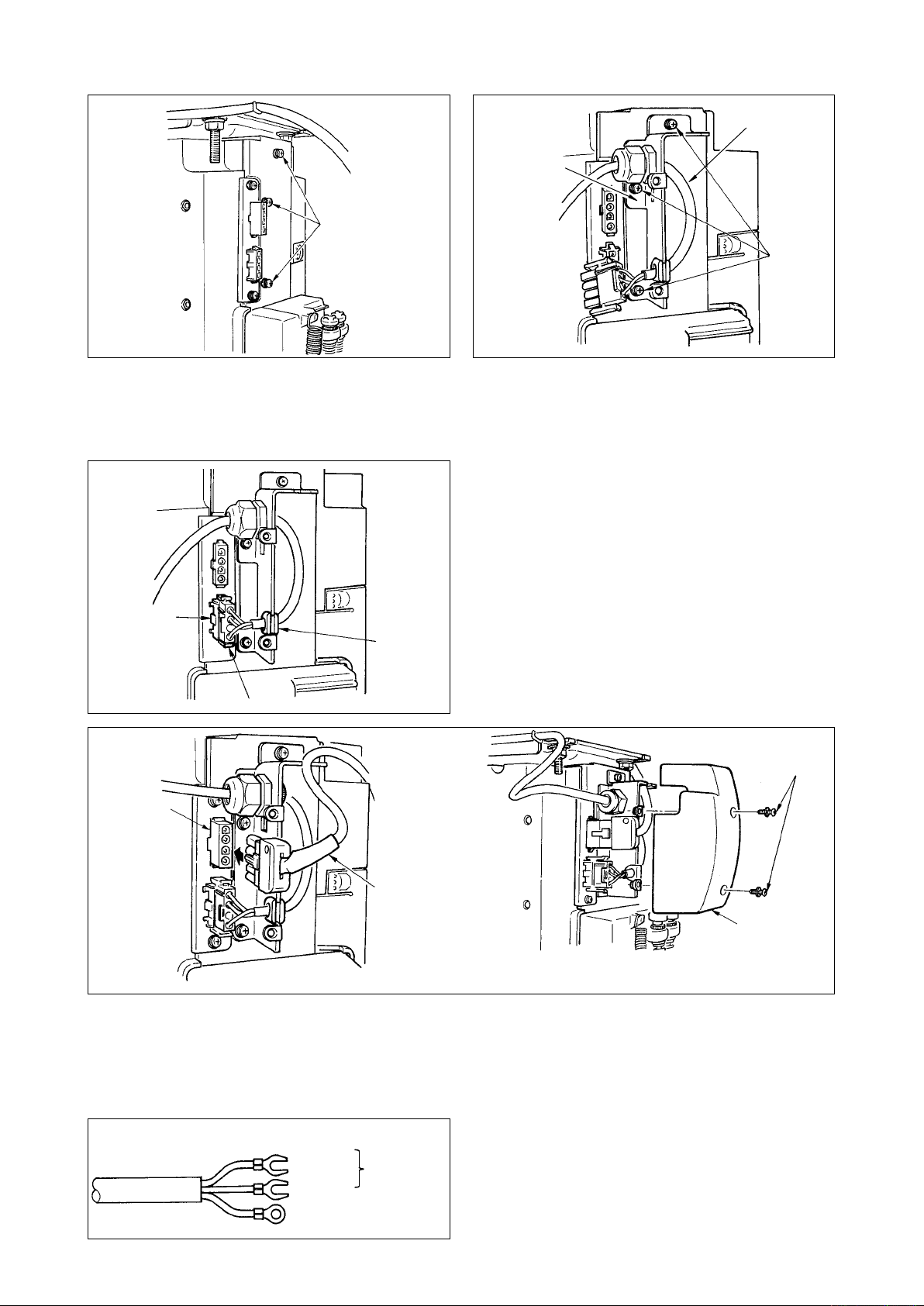
15) Remove three screws 1 located on the side of
the control box.
6
7
5
9
16) Set power source cord set 3 and installing
plate 4 supplied with the unit as accessories as
shown in the gure, and x them to the control
box main unit with three setscrews 2 which have
been removed.
17) Connect connector 5 coming from the power
source cord to lower connector 6 after checking
the direction.
(Caution) When rubber bush 7 is off the install-
ing plate, adjust it to the groove of the
installing plate and insert it.
!1
8
!0
18) Connect motor output cord 8 to connector 9 located on the side of the box.
19) Fix power source cover !0 supplied with the unit using two screws !1 supplied with the unit.
(Caution) At this time, be careful so that the motor output cord is not caught by the power source
cover and so that the cord enters the recess of the power source cover.
CE 1ø 230V
Brown
Blue
Green / Yellow
(ground wire)
AC
220V-240V
20) Installing power switch
Connect power supply cord to the power switch.
[CEspecications]
Single phase 230V : Power supply cords :
Brown, Blue
and green/yellow (ground wire)
– 8 –
,
Page 11
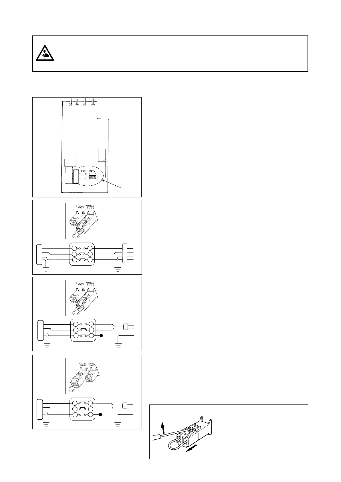
[Power voltage changeover procedure (power voltage setting procedure)]
WARNING :
To prevent personal injuries caused by electric shock hazards or abrupt start of the sewing machine,
carry out the work after turning OFF the power switch and a lapse of 5 minutes or more. To prevent
accidents caused by unaccustomed work or electric shock, request the electric expert or engineer of
our dealers when adjusting the electrical components.
It is adaptable to the voltage of single phase 100V to 120V/3-phase 200V to 240V by changing the voltage
changeover connector mounted on FLT p.c.b.
(Caution) When the changing procedure is wring, the control box will be broken. So, be very careful.
Changing procedure of the changeover connector
1. Turn OFF the power source with the power switch after
conrming that the sewing machine has stopped.
2. Draw out the power cord from the power plug socket after
conrming that the power switch is turned OFF. Then wait
for ve minutes or more.
3. Remove the front cover.
4. Remove three screws xing the rear cover of the control
box and slowly open the rear cover.
¥
.
A
B
C
WHITE
BLACK
RED
GREEN/
YELLOW
WHITE
BLACK
RED
GREEN/
YELLOW
WHITE
BLACK
RED
GREEN/
YELLOW
WHITE
BLACK
RED
GREEN/
YELLOW
WHITE
BLACK
RED
GREEN/
YELLOW
WHITE
BLACK
RED
GREEN/
YELLOW
1
(Plug side)
(Plug side)
(Plug side)
A. In case of using with 3-phase 200V to 240V
• Changing the changeover connector
Connect to 200V the 100/200V changeover connector of
FLT p.c.b. 1.
• Connect the crimp style terminal of AC input cord to the
power plug as shown in the gure.
B. In case of using with single phase 100V to 120V
• Changing the changeover connector
Connect to 100V the 100/200V changeover connector of
FLT p.c.b. 1.
• Connect the crimp style terminal of AC input cord to the
power plug as shown in the gure.
(Caution) Securely perform the insulation treatment to the
red terminal which is not used with insulation tape or
thelike.(Whentheinsulationisinsufcient,thereisa
danger of electric shock or leakage current.)
C. In case of using with single phase 200V to 240V
• Changing the changeover connector
Connect to 200V the 100/200V changeover connector of
FLT p.c.b. 1.
• Connect the crimp style terminal of AC input cord to the
power plug as shown in the gure.
(Caution) Securely perform the insulation treatment to the
red terminal which is not used with insulation tape or
thelike.(Whentheinsulationisinsufcient,thereisa
danger of electric shock or leakage current.)
5. Check that the change has been performed without fail before closing the rear cover.
6. Be careful that the cord is not pinched between the rear
cover and the control box main unit. Close the rear cover
while pressing the lower side of rear cover, and tighten
three screws.
[Point when inserting/drawing out the connector]
When it is difficult to remove the
chang eover connector, insert a
small-sized screwdriver and press in
the direction of the arrow as shown
in the gure, and the connector can
be removed with ease
ENGLISH
– 9 –
Page 12
[In case of using the power switch for LA]
It is necessary to separately purchase the parts below.
JUKI Part No. Description Q'ty Remarks
40012006 Set A for LA 1 For 3-phase 200 to 240V
40012007 Set B for LA 1 For single phase 100 to 120V
In addition, separately prepare the power switch for LA.
1
2
3
15) Remove three screws 1 located on the side
of the control box.
7
5
6
4
9
16) Tighten cover installing ttings 2 to the control
box main unit with three screws 3 which have
been removed in step 15).
17) Connect connector 4 coming from the power
source cord to lower connector 5 after checking
the direction.
(Caution) Adjust rubber bush 6 to the groove of
installing plate and insert it.
18) Pass nut 7 supplied with the power switch for
LA through the power cord and insert the cord
into the conduit (arrow mark).
Securely x it to the installing ttings with nut
7
from both sides.
!1
8
!0
19) Connect motor output cord 8 to connector 9 located on the side of the box.
Fix power source cover !0 supplied with the unit using two screws !1 supplied with the unit.
(Caution) At this time, be careful so that the motor output cord is not caught by the power source
cover and so that the cord enters the recess of the power source cover.
– 10 –
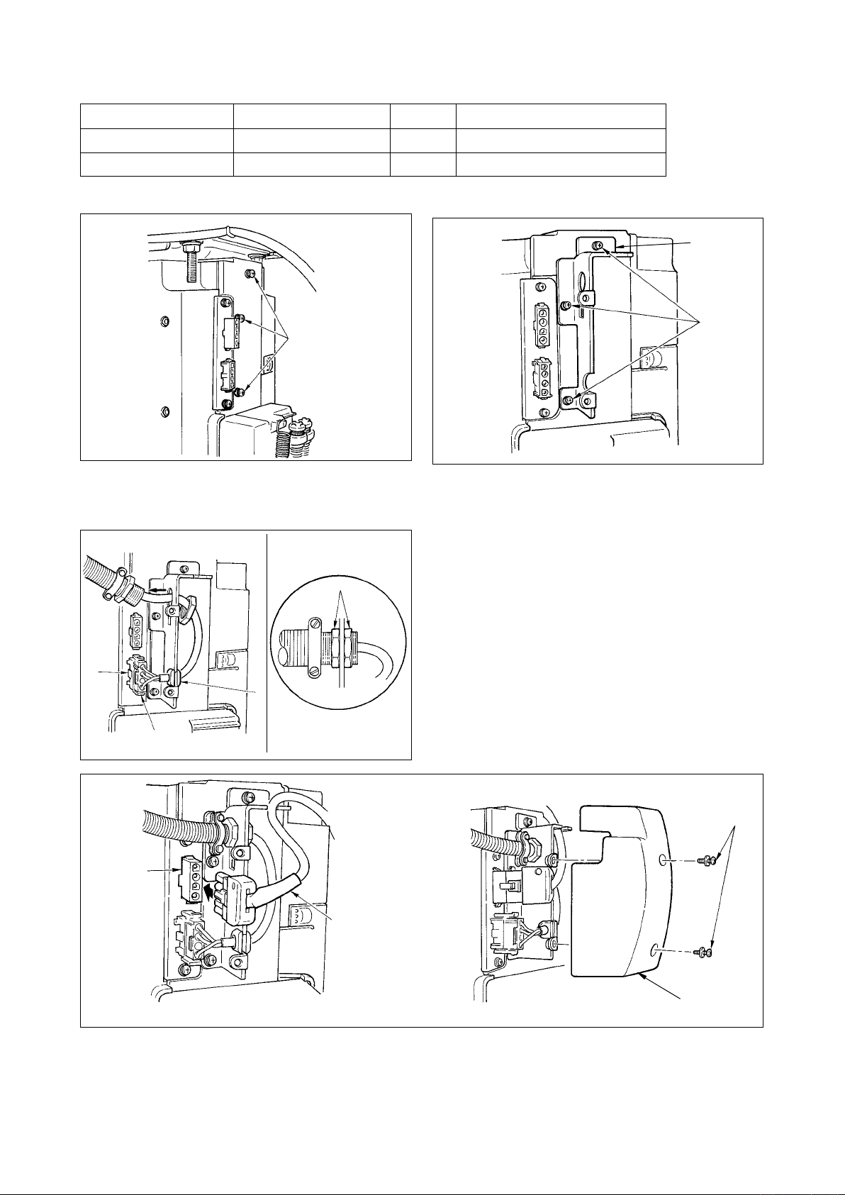
Page 13
JA 3ø 220V
JA 1ø 120V
Black
Red
White
Green / Yellow
(ground wire)
Black
White
Green / Yellow
(ground wire)
AC
200V-240V
AC
100V-120V
@1
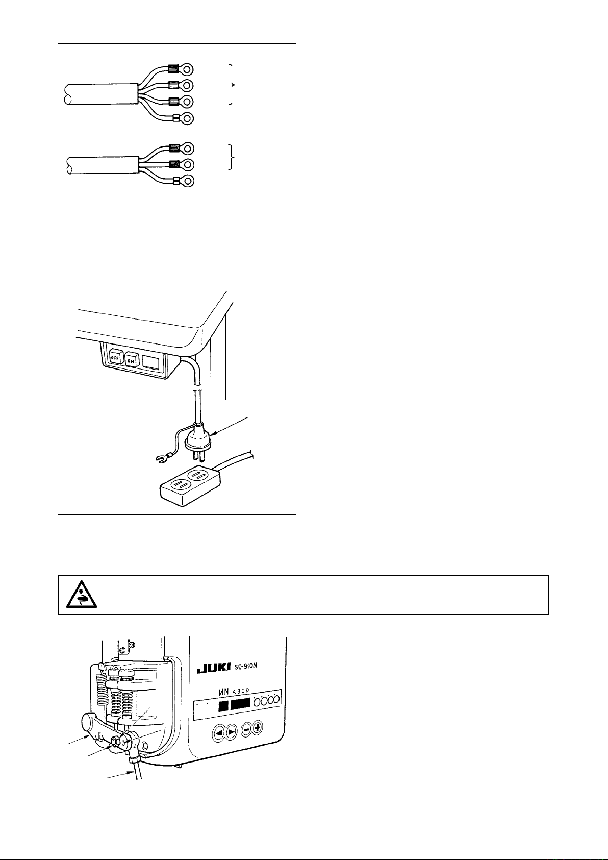
20) Installing power switch
Connect power supply cord to the power switch.
[JA specications]
3-phase 220 V : Power supply c o r d s : b l a c k ,
white, r e d a n d g r e e n / y e l l o w
(ground wire)
Single phase 120V : Power s u p p l y c o r d s : b l a c k ,
white, and green/yellow (ground
wire)
21) Make sure that the power switch is turned OFF
and insert power supply cord @1 coming from the
power switch into the power plug socket. (Illustra-
tion is for the japanese specication 100V type.)
(Caution) 1. Top end of power supply cord
@1
varies in accordance with destina-
tion or supply voltage. Check again
the supply voltage and the voltage
designated on the control box when
installing the switch.
2. P rep a r e t h e p o wer sw i t ch con -
formed to the safety standard.
3. Be sure to connect the ground wire (
green / yellow).
6. Attaching the connecting rod
WARNING :
To protect against possible personal injury due to abrupt start of the machine, be sure to start the
following work after turning the power off and a lapse of 5 minutes or more.
3
A
2
B
1
1) Fix connecting rod 1 to installing hole B of ped-
al lever 2 with nut 3.
2) Installing connecting rod 1 to installing hole A
will lengthen the pedal depressing stroke, and
the pedal operation at a medium speed will be
easier.
– 11 –
Page 14
7. Setting procedure of the machine head
WARNING :
When the machine head other than DDL-9000A is used, the work of items 7, 8 and 9 is not
necessary. The machine head is automatically selected by inserting the machine head connector.
1) Refer to
910N" p.22
"#-4. Setting for functions of SC-
, and call the function setting No. 95.
2) The type of machine head can be selected by
pressing switch 3 ( switch 4).
1
2
3
4
3) After selecting the type of machine head, by
pressing switch 1 ( switch 2), the step
proceeds to 96 or 94, and the display automati-
cally changes to the contents of the setting cor-
responding with the type of machine head.
(Caution) W hen the t y p e of mach i n e head is
changed, the contents which have
been changed b e f o r e r e t u r n t o t h e
standard set values.
– 12 –
Page 15
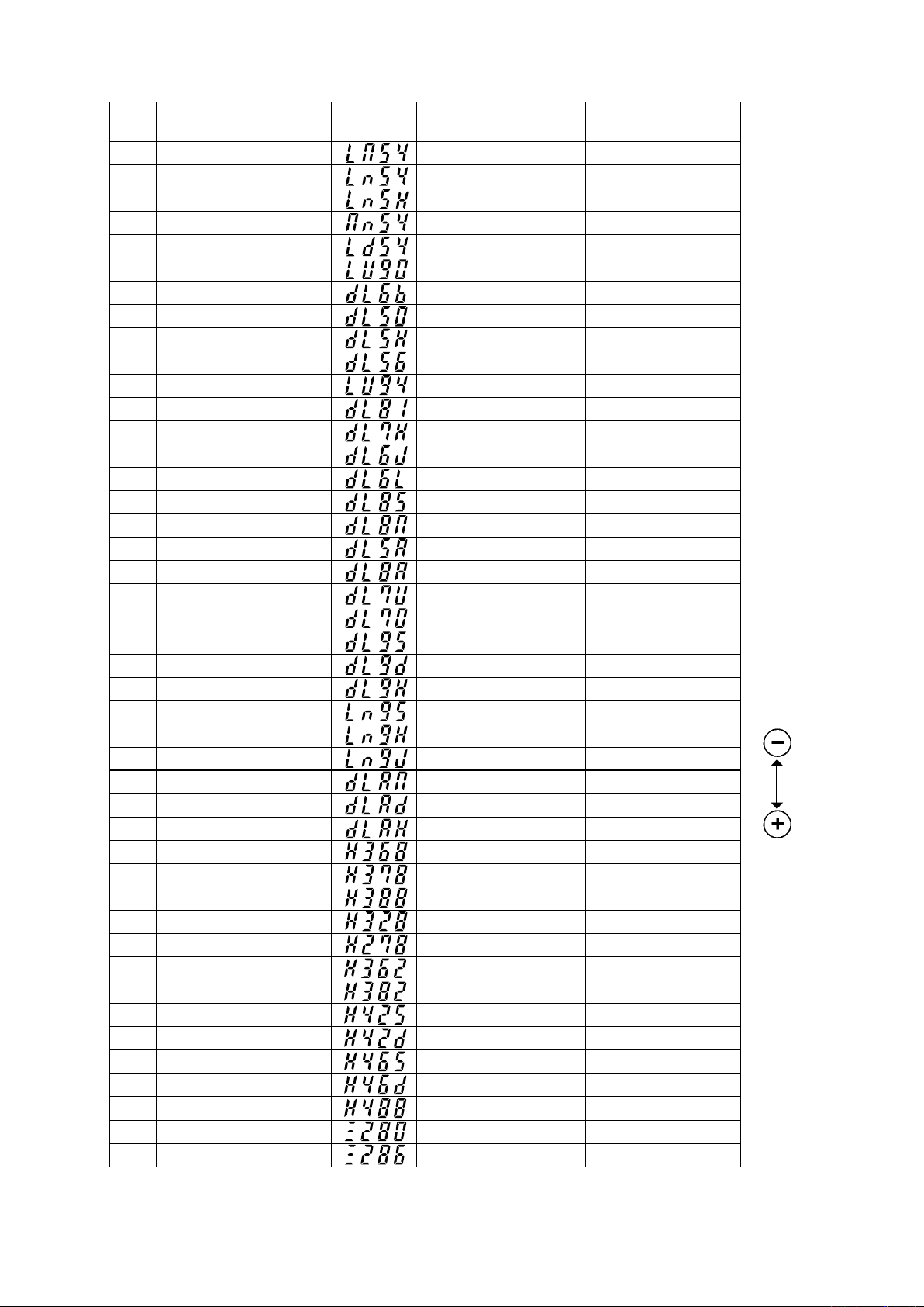
8. Machine head list
No. Machine head
Contents
of display
Number of revolutions at
the time of delivery (rpm)
1 DLM-5400 4000 4500
2 DLN-5410 4000 5000
3 DLN-5410H 3500 4000
4 DMN-5420 4000 5000
5 DLD-5430 4000 4500
6 DLU-5490 4000 4500
7 DDL-5600B 3700 4000
8 DDL-5550, DDL-8700 4000 5000
9 DDL-5550H 3500 4000
10 DDL-5556 4000 4000
11 DLU-5494 3500 4000
12 DDL-5581 4000 5000
13 DDL-5571H 3500 4000
14 DDL-5600J 4000 4000
15 DDL-5600L, U, R 3000 3000
16 DDL-5581S 2000 3500
17 DDL-5581M 4000 4000
18 DDL-5550A 4000 4000
19 DDL-5581A, K 4000 4000
20 DDL-5571U 3500 3500
21 DDL-5700 4000 4000
22 DDL-9000S 4000 5000
23 DDL-9000D 4000 4000
24 DDL-9000H 4000 4500
25 DLN-9010S 4000 5000
26 DLN-9010H 3500 4000
27 DLN-9010J 3500 4000
28
*
DDL-9000A SS/MA/MS
4000 5000
29 DDL-9000A DS 4000 4000
30 DDL-9000A SH 4000 4500
31 LH-3168 3000 3000
32 LH-3178 3000 3000
33 LH-3188 3000 3000
34 LH-3128 3000 3000
35 LH-2178 4000 4000
36 LH-3162 3000 3000
37 LH-3182 3000 3000
38 LH-4128S 3600 4000
39 LH-4128D 3000 3000
40 LH-4168 3200 3200
41 LH-4168D 3000 3000
42 LH-4188 3200 3200
43 LZ-2280 4000 5000
44 LZ-2286 4000 5000
Max. number of
revolutions (rpm)
ENGLISH
Machine head set at the time of delivery
*
– 13 –
Page 16

9. Adjusting the machine head (DDL-9000A only)
WARNING :
When the slip between the white marker dot on the handwheel and the concave of the cover is
excessive after thread trimming, adjust the angle of the machine head by the operation below.
A
1) Simultaneously pressing switch 2 and
switch 3, turn ON the power switch.
2) is displayed (A) in the indicator and the
mode is changed over to the adjustment mode.
2
3
3) Turn the handwheel by hand and angle B is dis-
B
played in the indicator when the reference signal
has been detected.
(The value is the reference value.)
6
4) In this state, align the white dot 5of the hand-
wheel with the concave 6of the pulley cover as
shown in the gure.
5
5) Press switch 4 to finish the adjustment
work.
(The value is the reference value.)
4
– 14 –
Page 17

#
. FOR THE OPERATOR
1. Operating procedure of SC-910N
12
Display of power ON
[When operation panel is not connected]
1) Press ON button 1 of the power switch to turn
ON the power.
(Caution) In case the power indication LED does
not lights up even when turning ON the
power switch,immediately turn OFF the
power and check the voltage.
In addition, in such a case as this, re-
turn ON the power switch when 2 to
3 minutes or more have passed after
turning OFF the power switch.
(When overv o ltage is inp u tted, the
protecting circuit works and re-turning
in the state that the power is not completely turned OFF is not received.)
ENGLISH
A
[When operation panel is connected]
B
When operation panel (CP-170, and IP-110) is not used
LED of the display of reverse stitching or overlapped stitching at
the front cover of control box lights up. (A)
* The power display LED that is built in the machine head
lights up according to the machine head.
When operation panel (CP-170, and IP-110) is used
Power lamp of CP-170 or IP-110 lights up.
Two dots B of the number indicating window at the front cover of
control box light up.
(Caution) When the buzzer continues sounding immedi-
ately after turning ON the power, the cord may
not be properly connected or power voltage may
be not proper. Press OFF button 2 of the power
switch to turn OFF the power.
2) When the needle bar is not in UP position, it automatically turns to the UP position.
(Caution) WhenturningONthepowerforthersttime,thereisthecasewherethetimingisslightly
retarded to perform the initialization work. When turning ON the power, the needle bar
moves. Do not put your hands or things under the needle.
3) When depressing front part 3 of the pedal, the
sewing machine rotates at the number of revolu-
tions in accordance with the depressing amount.
5
4
3
When the pedal is returned to the neutral posi-
tion, the sewing machine stops.
4) When lightly depressing back part 4 of the ped-
al, the presser goes up. (PFL type only)
5) When strongly depressing back part 5 of the
pedal, thread trimming is performed.
(Caution) For KFL a n d PFL types , thread
trimming entering point is different
from each other.
– 15 –
Page 18

6
6) When operation panel 6 is connected, various
sewing patterns such as reverse feed stitching
at sewing start, reverse feed stitching at sewing
end, etc. can be set.
Refer to the Instruction Manual for the operation
panel for the details.
7) When pressing touch-back switch 7, reverse
feed can be performed.
7
2
8
8) When sewing is completed, press OFF button
2
of the power switch to turn OFF the power switch
after confirming that the sewing machine has
stopped.
(Power indication LED 8 built in the machine
head goes out in case of some machine heads.)
– 16 –
Page 19

2. Explanation of the operation panel
7
3
8
4
9
!0
!1
!2
A
1
B
6
1
2
5
/
switch : Used for determining the contents of setting.
When this switch is pressed, ashing stops and the contents of
setting are determined.
2
/
switch : Used for changing the contents of setting.
When this switch is pressed, changeable positions ash on and off.
By pressing the switch, ashing position shifts in the right direction.
ENGLISH
3
switch : Used for changing the contents of the selected display (ashing
section).
When this switch is pressed, the contents of the display decrease.
switch : Used for changing the contents of the selected display (ashing
4
section). When this switch is pressed, the contents of the display
increase.
PATTERN SELECTION display : The selected LED lamp lights up in case of A reverse stitching
5
LED and B overlapped stitching.
REVERSE STITCHING : Rendered effective when reverse stitching pattern is selected.
6
AT START display
REVERSE STITCHING : Rendered effective when reverse stitching pattern is selected.
7
AT END display
NUMBER OF STITCHES display : Number of stitches of reverse stitching or overlapped stitching is
8
“ ” Without reverse stitching display / “
“
” Double reverse stitching display
“ ” Without reverse stitching display / “
“
” Double reverse stitching display
” Reverse stitching display /
” Reverse stitching display /
displayed.
AUTOMATIC : Lights up when the automatic thread trimming by depressing the
9
THREAD TRIMMING display front part of the pedal is selected.
(Lights up when the overlapped stitching is selected.)
THREAD TRIMMING : Lights up when the thread trimming prohibition is selected.
!0
PROHIBITION display Function setting No. 9
ONE-SHOT AUTOMATIC : Lights up when the one-shot automatic stitching is selected.
!1
STITCHING display (Lights up when the overlapped stitching is selected.)(Lights up when the overlapped stitching is selected.)
MATERIAL END SENSOR : Lights up when the material end sensor setting is selected.
!2
display Function setting No. 2
– 17 –
Page 20

3. Operating procedure of the sewing pattern
(1) Reverse stitching pattern
Reverse stitching patterns below can be set by using the operation panel.
Reverse stitching patterns that can be set
Reverse stitching
at start display
A
B
Sewing pattern
Reverse stitching
at end display
Reverse stitching pattern
LED lights Up. LED lights Up.
Overlapped stitching pattern
⇔
1 2 1 2
A
A
D
C
D
C
A
B
B B
DCD
A
BAB
DCD
C
A
DCD
C
A
B
C
BAB
D
C
[ Setting procedure of the reverse stitching ]
1) Hold pressing / switch 2, and press
/ switch 1 to select the reverse stitch-
ing pattern.
(Every time / switch 1 is pressed, re-
verse stitching pattern/overlapped stitching pat-
tern change over alternately.)
6
Flash
2
7
Shift direction
Flash
Contents of reverse
stitching selection
updating with switch
updating with switch
2) Press / switch 2 to make reverse stitch-
ing at start display 6 ash on and off.
Every time / switch 2 is pressed, the
ashing position shifts in the right direction.
(Caution) The sewing machine does not start in
theashingstate.
3) Press switch 4 or switch 3 and select
the reverse stitching pattern. Reverse stitching
4
patterns and displays are as follows.
: Reverse stitching
: Double reverse stitching
3
: Without reverse stitching
2
3 4
4) Press / switch 2 to make reverse stitch-
ing at end display 7 ash on and off, and set the
pattern in the same way as step 3).
– 18 –
Page 21

Flash
8
5) Press / switch 2 to make number of
stitches display 8 ash on and off, and set the
number of stitches for the respective processes
of the stitching.
6) Press switch 4 or switch 3 to change
the number of stitches.
The number of stitches can be changed up to as
many as 15 stitches for the A, B, C, and D pro-
1 2 3 4
cesses respectively.
However, displays are as follows.
10 stitches = A, 11 stitches = b, 12 stitches = c, 13
stitches = d, 14 stitches = E and 15 stitches = F
7) When the setting of all items has been completed,
press / switch 1 to determine the con-
tents of the setting. (Flashing stops.)
(2) Overlapped stitching pattern
Overlapped stitching patterns below can be set by using the operation panel.
ENGLISH
A
B
Reverse stitching pattern
LED lights Up. LED lights Up.
C
B
D
C
Overlapped stitching pattern
⇔
1
2
A : Number of stitches of normal stitching setting
0 to 15 (F) stitches
B : Number of stitches of reverse stitching setting
0 to 15 (F) stitches
C : Number of stitches of normal stitching setting
0 to 15 (F) stitches
D : Number of times of repetition
0 to 9 times
(Caution) When process D is set to 5 times, the sewing is re-
peated as A / B / C / B / C.
[Setting procedure of the overlapped stitching]
1) Hold pressing / switch 2, and press
/ switch 1 to select the overlapped stitching
pattern.
(Every time / switch 1 is pressed, re-
verse stitching pattern/overlapped stitching pattern change over alternately.)
2) The number of stitches for process A becomes in
1
2
ashing state.
3) Every time / switch 2 is pressed, the
Flash
1
2 3 4
ashing position shifts in the right direction and
the display of the process where setting can be
changed ashes on and off.
4) Press switch 4 or switch 3 to change
the number of stitches.
5) When the setting of all processes has been com-
pleted, press / switch 1 to determine
the contents of the setting. (Flashing stops.)
(Caution) When the overlapped stitching is se-
lected, the automatic operation display
ashesonandoff.Itisnotpossibleto
release the automatic operation.
– 19 –
Page 22

(3) Special setting
It is possible to change the set value in the front panel by directly moving to the function setting mode while
the power is turned ON in addition to the normal function setting procedure.
[ Moving procedure to the function setting mode ]
1) Hold pressing / switch 2, and press
switch 4 to move to the function setting
mode.
(Caution) Function setting No. 2 is displayed im-
mediately after the changeover.
2) When returning to the normal mode, press /
1 2 3 4
1 2 3 4
switch 1 and determine the contents of the
setting.
Material end sensor function setting (Function
1
setting No. 2)
It is rendered effective when connecting the op-
tional material end sensor.
It is possible to change the set value with
switch 3 or switch
4
.
0 : Material end sensor function is prohib-
ited.
1 : Material end sensor function is effective.
When "1" is selected, material
end s ensor disp l ay lights u p
when the mode has returned to
the normal one.
Thread trimming operation after material end
2
stop setting (Function setting No. 3)
1 2 3 4
Press / switch 2 to advance to the func-
tion setting No. 3.
It is possible to change the set value with
switch 3 or switch
4
.
0 : Material end stop
1 : Automatic thread trimming after detec-
tion of material end
When "1" is selected, the auto-
matic thread trimming display
lights up when the mode is re-
turned to the normal one.
– 20 –
Page 23

Number of stitches to stop the sewing machine
3
after detection of material end setting (Function
setting No. 4)
Press / switch 2 to advance to the func-
tion setting No. 4.
It is possible to change the set value with
1 2 3 4
1 2 3 4
switch 3 or switch 4.
Specied number of stitches : 0 to 19 stitches
(Caution)Whenthespeciednumberofstitches
is insufficient, there is a case where
the sewing machine cannot stop within
the specified number of stitches de-
pending on the speed of rotation of the
sewing machine.
One-shot automatic stitching setting function
4
(Function setting No. 119)
Press / switch 2 to advance to the func-
tion setting No. 119.
It is possible to change the set value with
switch 3 or switch 4.
0 : Pedal designated speed is prior.
1 : Automatic operation
(Caution) It is rendered effective when the mate-
rial end sensor function is set.
It is not possible to prohibit the one-
shot operation at the time of the overlapped stitching operation.
Speed of rotation is the speed set at
the function setting No. 38.
When "1" is selected, the oneshot automatic stitching display
lights up when the mode is returned to the normal one.
ENGLISH
1 2 3 4
Thread trim ming p rohib ition f unction setting
5
(Function setting No. 9)
Thread trimming operation at normal stitching
and overlapped stitching can be prohibited by se-
lecting the thread trimming prohibition.
It is possible to change the set value with
switch 3 or switch 4.
0 : Thread trimming is effective.
1 : Thread trimming is prohibited.
Wh en " 1" i s se l e c t e d , t he
thread trimming prohibition dis-
play lights up when the mode
is returned to the normal one.
– 21 –
Page 24

4. Setting for functions of SC-910N
Functions can be selected and specied by means of the four setting switches and light emitting diode lo-
cated inside the front cover of the SC-910N.
Speciedvalue
(Caution)
SpeciedNo.
1 3 42
Switch for entering specied value changed
1
and updating setting No. in DOWN direction
Switch for entering specied value changed
2
and updating setting No. in UP direction
Down switch (DOWN)
3
Up switch (UP)
4
• Do not perform switch operations other than those described in the following explanations.
• Be sure to re-turn the power switch ON after one second or more has passed. If the
power is turned ON immediately after turning it OFF, the sewing machine may not
work normally. In this case, turn ON the power again.
WARNING :
To avoid possible personal injuries caused by movement other than that you desired, do not
operate the switches in the procedure other than those required, as described below, to specify the
functions.
How to change over to the function setting mode
1) Turn OFF the power to the unit.
2) Pressing switch 4, turn ON the power to the
unit.
4
3) Indication 5 and 6 will be shown on the screen
display.
(The indication item shows the item, the setting
of which was changed the last time.)
* If the indication fails to change, re-perform the
procedures 1) and 2).
6
5
– 22 –
Page 25

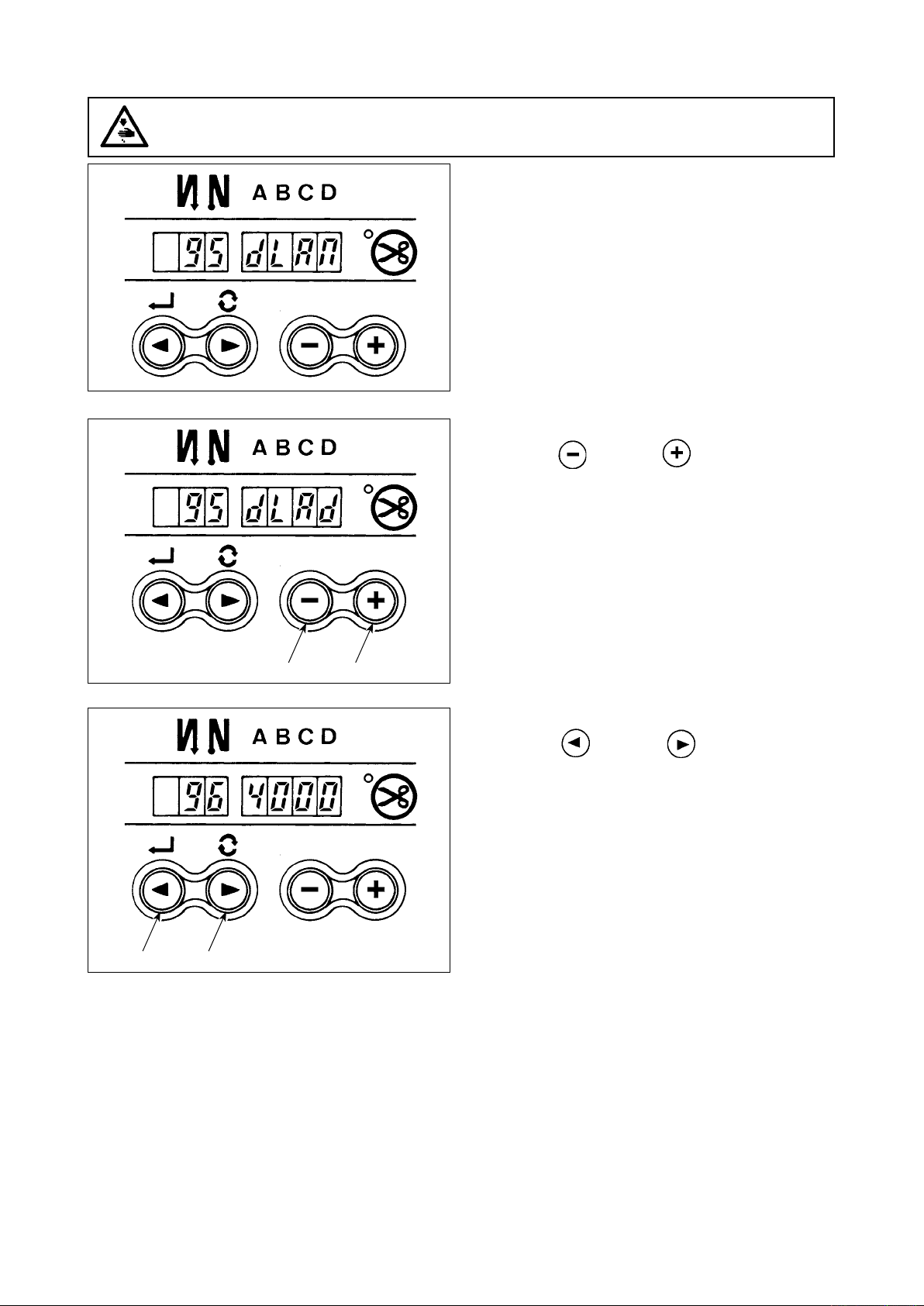
SpeciedNo.
4) When you want to advance the setting No., press
/ switch 2 to advance the setting No.
When you want to return the setting No., press
/ switch 1 to return the setting No.
1 2
5
(Caution) Wh e n
/
sw i t c h 1 (
/
switch 2) is held pressing, the setting
No. will return (will advance) continuously.
When the setting No. is advanced (re-
turned), the contents which are before
by o ne (after b y one) will b e deter-
mined. So, be careful when changing
the contents ( up/down switch
is touched).
EXAMPLE) CHANGING THE FLICKER REDUCING
FUNCTION (SETTING No. 5)
Press / switch 2 several times to adjust set
No. to “5”. Press switch 4 three times to change the
set No. to “3” since the current set value is displayed
on LED 5. (Standard : “0”)
(Caution) Keep pressing switch 4 or
switch 3, and the setting value can be
changed continuously.
ENGLISH
1 2 3 4
5) When the change has been completed, press
5
/ switch 1 or / switch 2 to
specify the changed value.
(Caution) 1. When turning OFF the power before
performing this work, the contents
which have been changed are not
updated.
2. P r e s s
/
sw i t c h 1, an d
screen display will change to the
contents of the setting No. which is
1 2 3 4
3. Press
before by one.
/
switch 2, and screen
display will change to the contents
of next setting No. After completing
the operation, turn OFF the power
and turn ON the power again to re-
turn to the normal operation.
After completing the operation, turn OFF the power and turn ON the power again to return to the normal
operation.
* Simultaneously press switch 3 and switch 4, and the setting contents of set No. will return to
the initial value.
– 23 –
Page 26

5. Function setting list
No
1 Soft start
2 Material end
3
4 Number of
5 Flicker reducing
6 Bobbin thread
7 Unit of bobbin
*
8 Number of
*
9 Thread
10 Setting of
11 Click sound
12 Optinal switch
13 Function of
*
14 Sewing counter Counting function of sewing (number of completion of process)
15
*
*
Do not change the set values with asterisk (*) mark as they are functions for maintenance. If the standard set value set at the
time of delivery is changed, it is in danger of causing the machine to be broken or the performance to be deteriorated.
If it is necessary to change the set value, please purchase the Engineer’s Manual and follow the instructions.
(Descriptions of setting in this list are the standard values at the time of delivery of DDL-9000A.)
However, contents of function setting are subject to change for improvement of function and performance without notice.
Item Description
function
sensor function
Thread trimming
function by
material end
sensor
stitches for
material end
sensor
function
counting
function
thread counting
down
rotation of
reverse feed
stitching
trimming
prohibiting
function
needle bar stop
position when
the sewing
machine stops.
of key switch
mounted on
PSC
function
selection
prohibiting start
of the sewing
machine by
bobbin thread
counter
Number of times
of detection of
run-out of bobbin
thread remaining
amount
The number of stitches to be sewn at a low speed when the softstart function is used at the start of sewing.
0 : Soft-start function is not operative.
Material end sensor function (used in case of without panel).
0 : Material end detection function is not operative.
1 : After de tecting material end, the speci fied number o f
stitches (No. 4) will be sewn, and the sewing machine will
stop.
Thread trimming function by material end sensor (used in case
of without panel).
0 : Automatic thread trimming function after detection of ma-
terial end is not operative.
1 : After de tecting material end, the speci fied number o f
stitches (No. 4) will be sewn, and the sewing machine will
stop and perform automatic thread trimming.
Number of stitches for material end sensor (used in case of without panel).
Number of stitches from detection of material end to stop of the
sewing machine.
Flicker reducing function (If the hand lamp ickers).
0 : Flicker reducing function is not operative.
1 : Less effective / 8 : Highly effective
Bobbin thread counting function
0 : Bobbin thread counting function is not operative.
1 : Bobbin thread counting function is operative.
Unit of bobbin thread counting down
0 : Count/10 stitches
1 : Count/15 stitches
2 : Count/20 stitches
Sewing speed of reverse feed stitching
Thread trimming prohibiting function (used in case of without panel).
0 : Thread trimming prohibiting function is not operative.
1 : Thread trimming is prohibited.
(Output of solenoid is prohibited. : Thread trimmer and wiper)
Position of needle bar is specified when the sewing machine
stops.
0 : Predetermined lowest position
1 : Predetermined highest position
Click sound of key switch mounted on PSC is specied.
0 : Click is not operative.
1 : Click is operative.
Switching of function of optional switch.
0 : No function
1 : Needle up/down compensating stitching
2 : Back compensating stitching
3 : Function of canceling once reverse feed stitching at the
end of sewing
4 : Thread trimming function
5 : Presser foot lifting function
6 : One stitch compensating stitching
7 : Function of simultaneously canceling reverse feed stitch-
ing at the start and end of sewing
8 : Function of neutral presser foot lifting changeover
Function of prohibiting start of the sewing machine by bobbin thread counting
0 : When counting is out (-1 or less) Function of prohibiting
start of the sewing machine is not operative.
1 : When counting is out (-1 or less) Function of prohibiting
start of the sewing machine after thread trimming is op-
erative.
2 : When counting is out (-1 or less), the sewing machine
stops once. Function of prohibiting start of the sewing
machine after thread trimming is operative.
0 : Sewing counter function is not operative.
1 : Sewing counter function is operative.
Number of times of detection of run-out of bobbin thread remaining amount
0 : Function of bobbin thread remaining amount is not
1 to 19 : Number of times during which the signal is not made
operative.
even if run-out of bobbin thread remaining amount is
detected.
Setting range
0 to 9
(Stitches)
0/1
0/1
0 to 19
(Stitches)
0 to 8
0/1
0 to 2
150 to 3,000
(r.p.m.)
0/1
0/1
0/1
0 to 8
0 to 2
0/1
0 to 19
Indication of function setting
1 0
2 0
3 0
4 5
5 0
6 1
7 0
8 1 9 0 0
9 0
1 0 0
1 1 1
1 2 0
1 3 0
1 4 1
1 5 1
Ref. page
31
31
31
31
31
31
32
32
– 24 –
Page 27

No
18 Bird’s nest pre-
vention function
*
19 Needle thread
*
*
*
*
*
release function
at the sewing
start
20 Number of
condensation
stitches
21 Function of
neutral presser
lifting
22 Function of
changeover of
compensating
switch on the
operation panel
function
24 Function of
ne adjustment
of number of
rotation
25 Thread trimming
motion condition
26 Function of
setting the
holding force
after stop
27 Function of
setting the
reaction force at
the time of retry
28 Number of
stitches of
needle thread
release
29 Initial motion
time of backtack
30 Function of
reverse feed
stitching on the
way
31
Number of
stitches of reverse
feed stitching on
the way
32 Effective
condition of
reverse feed
stitching on the
way when the
sewing machine
is stopping.
33 Thread trimming
function by
reverse feed
stitching on the
way
35 Number of
rotation at a low
speed
36 Number of
rotation of
thread trimming
37 Number of
rotation of softstart
Item Description
This function is effective in combination with the machine head
with bird's nest prevention function (optional unit A is necessary).
0 : Bird's nest prevention function is not operative.
1 : Bird's nest prevention function is operative.
2 : Bird's nest prevention function is operative (with thread
release).
This function is effective in combination with the machine head
with bird's nest prevention function (optional unit A is necessary).
0 : Needle thread release function is not operative.
1 : Needle thread release function is operative.
This function is effective in combination with the machine head
with bird's nest prevention function (optional unit A is necessary).
0 : Condensation function is not operative.
1 to 9 : Number of condensation stitches
Function of lifting presser foot when the pedal is in neutral position.
0 : Function of neutral automatic presser lifting is not opera-
tive.
1 : Selection of function of neutral presser lifting.
Function of needle up/down compensating switch on the operation panel can be changed.
0 : Needle up/down compensation
1 : One stitch compensation
Number of rotation can be compensated.
Be sure to normally use this function with "0".
This function sets the thread trimming motion after DOWN position has been off by turning handwheel by hand.
0 : Thread trimming after turning handwheel by hand is permitted.
1 : Thread trimming after turning handwheel by hand is prohib
This function prevents the sewing machine from the reverse rotation after it has stopped.
0 : Initial value
1 : Less effective / 9 : Highly effective
This function sets the magnitude of return force of the needle
bar before the retry motion.
1 : Less return force / 100 : High return force
This function is effective in combination with the machine head
with bird's nest prevention function (optional unit A is necessary).
This function sets the number of stitches grasping thread at the
sewing start.
0 to 30 stitches
This function sets the suction time of initial motion of back-tack
solenoid.
50 ms to 300 ms
Function of reverse feed stitching on the way
0 : Function of reverse stitching on the way is not operative.
1 : Function of reverse feed stitching on the way is operative.
Number of stitches of reverse feed stitching on the way.
Effective condition of reverse feed stitching on the way
0 : Function is not operative when the sewing machine stops.
1 : Function is operative when the sewing machine stops.
Thread trimming function by reverse feed stitching on the way
0 : Automatic thread trimming function after completion of
reverse feed stitching on the way is not operative.
1 : Automatic thread trimming after completion of reverse
feed stitching on the way is performed.
Lowest speed by pedal
Thread trimming speed
Sewing speed at the start of sewing (soft-start)
ited.
Setting range
0 to 2
0/1
0 : Function
OFF
1 to 9
stitches
0/1
0/1
– 1.5% to
1.5%
(0.1 %)
0/1
0 to 9
1 to 100
0 to 30
(Stitches)
50 to 300
(ms)
0/1
0 to 19
(Stitches)
0/1
0/1
20 to 400
(r.p.m.)
20 to 250
(r.p.m.)
150 to 5500
(r.p.m.)
Indication of function setting
1 8 0
1 9 0
2 0 0
2 1 0
2 2 0
2 4 0
2 5 1
2 6 0
2 7 5 0
2 8 1
2 9 2 5 0
3 0 0
3 1 4
3 2 0
3 3 0
3 5 2 0 0
3 6 2 1 0
3 7 8 0 0
Ref. page
32
32
32
33
33
33
33
33
32
34
34
34
34
34
31
*
Do not change the set values with asterisk (*) mark as they are functions for maintenance. If the standard set value set at the
time of delivery is changed, it is in danger of causing the machine to be broken or the performance to be deteriorated.
If it is necessary to change the set value, please purchase the Engineer’s Manual and follow the instructions.
(Descriptions of setting in this list are the standard values at the time of delivery of DDL-9000A.)
However, contents of function setting are subject to change for improvement of function and performance without notice.
– 25 –
Page 28

No
38 One-shot speed One-shot speed (The max. value depends on the number of ro-
39 Pedal stroke
*
40 Low speed
*
41 Starting position
*
42 Starting position
*
43
*
44
*
45
*
46
*
47
*
48
*
49
51 Compensation of
52 Compensation of
53 Compensation of
55
56
57
58
59
Item Description
tation of the sewing machine head.)
at the start of
rotation
section of pedal
of lifting presser
foot by pedal
of lowering
presser foot
Pedal stroke 2 for
starting thread
trimming
Pedal stroke
for reaching the
maximum number
of rotation
Compensation of
neutral point of
the pedal
Auto-lifter
selecting function
Auto-lifter
selecting function
Pedal stroke 1 for
starting thread
trimming
Lowering time of
presser foot
solenoid-on timing
of reverse feed
stitching at the
start of sewing
solenoid-off timing
of reverse feed
stitching at the
start of sewing
solenoid-off timing
of reverse feed
stitching at the
end of sewing
Foot lift after
thread trimming
Reverse
revolution to lift
the needle after
thread trimming
Bobbin thread
remaining amount
detection function
Function
of holding
predetermined
upper/lower
position of the
needle bar
Function of Auto/
Manual changeover of reverse
feed stitching at
the start of sewing
Position where the sewing machine starts rotating from pedal
neutral position (Pedal stroke)
Position where the sewing machine starts accelerating from
pedal neutral position (Pedal stroke)
Position where the cloth presser starts lifting from pedal neutral
position (Pedal stroke)
Starting position of lowering presser foot
Stroke from the neutral position
Position 2 where the thread trimming starts from pedal neutral
position(When the function of lifting presser foot by pedal is pro-
vided.) (Pedal stroke)
Position where the sewing machine reaches its highest sewing
speed from pedal neutral position (Pedal stroke)
Compensation value of the pedal sensor
Auto-lifter selection
0 : Solenoid drive system
1 : Pneumatic drive system
Limitation time of waiting for lifting solenoid type auto-lifter device
Position where thread trimming starts from pedal neutral position
(Standard pedal) (Pedal stroke)
Lowering time of presse r foot after the pedal has been depressed.
(Start of rotation of the sewing machine is delayed during this
time.)
Compensation of starting the solenoid for reverse feed stitching
when reverse feed stitching at the start of sewing is performed.
Compensation of releasing the solenoid for reverse feed stitching when reverse feed stitching at the start of sewing is performed.
Compensation of releasing the solenoid for reverse feed stitching when reverse feed stitching at the end of sewing is performed.
Function of lifting presser foot at the time of (after) thread trimming
0 : Not provided with the function of lifting presser foot after
thread trimming
1 : Provided with the function of lifting presser foot
after thread trimming
Function of reverse revolution to lift the needle at the time of (after) thread trimming
0 : Not provided with the function of reverse revolution to lift
the needle after thread trimming
1 : Provided with the function of reverse revolution to lift the
needle after thread trimming
Function of detecting bobbin thread remaining amount at the
time of (after thread trimming
0 : Not provided with the function of detecting bobbin thread
remaining amount
1 : Provided with the function of detecting bobbin thread re-
maining amount
Function of holding predetermined upper/lower position of the needle bar
0 : Not provided with the function of holding predetermined up-
per/lower position of the needle bar
1 : Provided with the function of holding predetermined upper/
lower position of the needle bar
This function can specify the sewing speed of reverse feed
stitching at the start of sewing.
0 : The speed will depend on the manual operation by pedal, etc.
1 :
The speed will depend on the specied reverse feed stitching speed (No. 8).
automatically
Setting range
200 to MAX
(r.p.m.)
10 to 50
(0.1 mm)
10 to 100
(0.1 mm)
– 60 to –10
(0.1mm)
8 to 50
(0.1 mm)
– 60 to –10
(0.1 mm)
10 to 150
(0.1 mm)
–15 to 15
0/1
10 to 600
(second)
– 60
to – 10
(0.1 mm)
0
to 250
(10 ms)
– 36 to 36
(10°)
– 36 to 36
(10°)
– 36 to 36
(10°)
0/1
0/1
0/1
0/1
0/1
Indication of function setting
3 8 2 5 0 0
3 9 3 0
4 0 6 0
4 1 – 2 1
4 2 1 0
4 3 – 5 1
4 4 1 5 0
4 5 0
4 6 0
4 7 6 0
4 8 – 3 5
4 9 1 4 0
5 1 – 1 8
5 2 – 5
5 3 – 5
5 5 1
5 6 0
5 7 0
5 8 0
5 9 1
Ref. page
35
35
37
35
35
35
36
36
36
36
36
*
Do not change the set values with asterisk (*) mark as they are functions for maintenance. If the standard set value set at the
time of delivery is changed, it is in danger of causing the machine to be broken or the performance to be deteriorated.
If it is necessary to change the set value, please purchase the Engineer’s Manual and follow the instructions.
(Descriptions of setting in this list are the standard values at the time of delivery of DDL-9000A.)
However, contents of function setting are subject to change for improvement of function and performance without notice.
– 26 –
Page 29

No
60
61
64
*
65
*
66
*
67
68
70
71
72
73
75
*
76
84
87
Item Description
Function of stop
immediately after
reverse feed
stitching at the
start of sewing
Function
of starting
prohibition of the
sewing machine
by detection of
bobbin thread
remaining amount
Changeover speed of
condensation
stitch or EBT (end
back tack)
On-timing of
solenoid for
condensation
stitch (when
condensation
stitch is performed
by 1 stitch.)
On-timing of
solenoid for
condensation
stitch (when
condensation
stitch is performed
by 2 stitches.)
Presser foot
lifting solenoid
output duty
setting
Separately
driven needle
changeover
speed-up
function
Function of softdown of presser
foot
Function of
limitation of reacceleration
from reduction of
speed
Function of
limitation of
acceleration at the
start of rotation
Retry function
Rotating direction
of motor
Function to select
the start-up speed
of the sewing
machine
Initial motion suction time of presser
foot lifting solenoid
Function of pedal
curve selection
Function at the time of completion of reverse feed stitching at
the start of sewing
0 : Not provided with the function of temporary stop of the
sewing machine at the time of completion of reverse feed
stitching at the start of sewing
1 : Provided with the function of temporary stop of the sew-
ing machine at the time of completion of reverse feed
stitching at the start of sewing.
Function of starting prohibition of the sewing machine by detection of bobbin thread remaining amount
0 : This function does not stop the sewing machine when
counting is out (-1 or less).
1 : This function stops the sewing machine when counting is
out (-1 or less).
Initial speed when starting condensation stitch or EBT
Starting (compensation) timing of solenoid for compensation
stitch : -1
Compensation value of starting the solenoid when condensation
stitch is performed by 1 stitch.
Starting (compensation) timing of solenoid for condensation
stitch : -2
Compensation value of starting the solenoid when condensation
stitch is performed by 2 stitches.
Duty of presser foot lifting solenoid output
Speed of separately driven needle changeover is set to highspeed.
0 : Standard
1 : High-speed
Presser foot is slowly lowered.
0 : Presser foot is rapidly lowered.
1 : Presser foot is slowly lowered.
Speed limitation is performed at the time of re-acceleration on
the way of
reducing speed of the sewing machine.
It is effective when operating inching sewing.
Speed limitation is performed at the time of start-up of the sewing machine (excluding the start of sewing).
It is effective when operating inching sewing.
This function is used when needle cannot pierce materials .
0 : Normal
1 : Retry function is provided.
Normal rotating direction of motor
0 : Clockwise
1 : Counterclockwise
Starting curve of the sewing machine is selected.
0 : Normal curve
1 : More sharp curve
Suction motion time of presser foot lifting solenoid
Pedal curve is selected. (Improving pedal inching operation)
Number of rotations
Setting range
0/1
0/1
0 to 250
(r.p.m.)
Indication of function setting
6 0 0
6 1 1
6 4 1 8 0
Ref. page
37
36
ENGLISH
– 36 to 0
(10°)
– 36 to 0
(10°)
5 to 40
0/1
0/1
0 to 5
0 to 5
0/1
0/1
0/1
40 to 300
(ms)
2
0
1
0/1/2
6 5 – 1 5
6 6 – 1 5
6 7 2 0
6 8 0
7 0 0
7 1 0
7 2 0
7 3 1
7 5 0
7 6 0
8 4 1 0 0
8 7 0
32
32
37
37
37
37
38
38
38
38
Pedal stroke
*
Do not change the set values with asterisk (*) mark as they are functions for maintenance. If the standard set value set at the
time of delivery is changed, it is in danger of causing the machine to be broken or the performance to be deteriorated.
If it is necessary to change the set value, please purchase the Engineer’s Manual and follow the instructions.
(Descriptions of setting in this list are the standard values at the time of delivery of DDL-9000A.)
However, contents of function setting are subject to change for improvement of function and performance without notice.
Items with mark are displayed when the machine heads of LH-4168, LH-4168D and LH-4188 are selected.
– 27 –
Page 30

No
89
*
90
91
*
92
93
94
95 Head selection
96
100 Number of
*
101 Sewing counter
105 Touch back
106 Presser lifting
107 In-corner
108
109
Item Description
Tension release
function
Initial motion up
stop function
Function of prohibiting
compensation
operation after turning
handwheel by hand
Function of
reducing speed
of reverse feed
stitching at the
start of sewing
Function added to
needle up/down
compensating
switch
Continuous
stitching + oneshot stitching nonstop function
function
Max. number of
rotation setting
stitches of
tension release
motion at the
sewing start
input function
switch needle
up/down
compensating
stitching
function
switch one stitch
compensating
function
sewing one-shot
function
In-corner presser
lifting function
Resewing
function
Setting range
This function is effective in combination with the machine head with
bird's nest prevention function (Optional unit A is necessary).
0 : Motion is prohibited.
1 : Motion of thread draw-out/return solenoid is prohibited.
Automatic UP stop function is set immediately after turning ON the
power.
0 : off
1 : on
It is effective in combination with the machine head provided
with tension release function.
0 : Tension release function is ineffective.
1 : Tension release function is effective.
Function to reduce speed at the time of completion of reverse
feed stitching at the start of sewing.
0 : Speed is not reduced.
1 : Speed is reduced.
Operation of needle up/down compensating switch is changed after
turning ON the power or thread trimming.
0 : Normal (needle up/down compensating stitching only)
1 : One stitch compensating stitching is performed only when aforemen-
tioned changeover is made. (Upper stop / upper stop)
In IP-110 program functions, a function that does not stop the sewing
machine by combining continuous stitching with one-shot stitching
when the step is changed.
0 : Normal (The sewing machine stops when a step is completed.)
1 : The sewing machine does not stop when a step is completed
and proceeds to next step.
Machine head to be used is selected.
* Whe n t he mac hine h ea d i s chang ed, each set tin g i tem is
changed to the initial value of the machine head.
Max. number of rotation of the sewing machine head can be set.
This function is effective in combination with the machine head with
bird's nest prevention function. (Optional unit A is necessary).
This function sets the number of stitches to make the tension release
solenoid actuate at the sewing start.
0 : Tension release motion is prohibited.
1 to 2 stitches : Number of stitches of tension release motion
This function selects the input destination of the sewing counter.
0 : Every time thread trimming is performed, the counter automati-
cally counts up.
1 :
The counter counts up by inputting of the external sewing counter SW
When connecting IP-110 and selecting the corner pattern, this function performs
compensating stitching during sewing in-corner with the touch back switch.
0 : Touch back switch compensating stitching is invalid.
1 : Touch back switch compensating stitching is valid.
* It is possible to set only when LH-4168 or LH-4188 is selected for
the machine head.
When connecting IP-110 and selecting the corner pattern, this function performs compensating stitching during sewing in-corner with the
presser lifting switch.
0 : Presser lifting switch compensating stitching is invalid.
1 : Presser lifting switch compensating stitching is valid.
* It is possible to set only when LH-4168 or LH-4188 is selected for
the machine head.
* When using this function, set the presser lifting switch function
selection (No. 117) to “0” (function invalid).
When connecting IP-110 and selecting the corner pattern, this
function performs one-shot automatic sewing of in-corner sewing.
0 : One-shot automatic sewing of in-corner sewing is invalid.
1 : One-shot automatic sewing of in-corner sewing is valid.
* It is possible to set only when LH-4168 or LH-4188 is se-
lected for the machine head.
When connecting IP-110 and selecting the corner pattern, this
function performs automatic presser lifting after completion of
the in-corner sewing.
0 : Automatic presser lifting after in-corner sewing is invalid.
1 : Automatic presser lifting after in-corner sewing is valid.
* It is possible to set only when LH-4168 or LH-4188 is se-
lected for the machine head.
* This function is valid only when the automatic presser lifting
device (AK) is connected.
When connecting IP-110, this function stops/uses resewing
(resewing from a point on the way).
0 : Resewing function is invalid.
1 : Resewing function is valid.
* It is possible to set only when LH-4168 or LH-4188 is se-
lected for the machine head.
0/1
0/1
0/1
0/1
0/1
0/1
50 to MAX
(rpm)
0 to 9
0/1
0/1
0/1
0/1
0/1
0/1
Indication of function setting
8 9 0
9 0 1
9 1 1
9 2 0
9 3 0
9 4 0
9 5 d L A
9 6 4 0 0 0
1 0 0 0
1 0 1 0
1 0 5 0
1 0 6 1
1 0 7 0
1 0 8 1
1 0 9 1
Ref. page
U
32
38
38
38
39
13
39
32
39
*
Do not change the set values with asterisk (*) mark as they are functions for maintenance. If the standard set value set at the
time of delivery is changed, it is in danger of causing the machine to be broken or the performance to be deteriorated.
If it is necessary to change the set value, please purchase the Engineer’s Manual and follow the instructions.
(Descriptions of setting in this list are the standard values at the time of delivery of DDL-9000A.)
However, contents of function setting are subject to change for improvement of function and performance without notice.
Items with mark are displayed when the machine heads of LH-4168, LH-4168D and LH-4188 are selected.
– 28 –
Page 31

No
110
Separately
driven needle
changeover
function (free
stitching/
overlapped
stitching)
111
Separately
driven needle
changeover
function (corner
pattern)
112
Teaching motion
selection
113
Number of
stitches of
teaching replay
114
Left bobbin thread
counter function
115
Right bobbin
thread counter
function
116
Corner teaching
start switch
selection
Item Description
When selecting reverse stitching pattern/overlapped stitching
pattern, this function stops/uses the separately driven needle
changeover function.
When “0” (invalid) is selected, the separately driven needle
changeover is not possible with reverse stitching pattern/overlapped stitching pattern.
0 : Separately driven needle changeover function (during free
stitching) is invalid.
1 : Separately driven needle changeover function (during free
stitching) is valid.
* It is possible to set only when LH-4168 or LH-4188 is se-
lected for the machine head.
When connecting IP-110 and selecting the corner pattern, this
function stops/uses the separately driven needle changeover
function.
When “0” is selected, it is not possible to optionally perform the
separately driven needle changeover with the corner pattern.
0 : Separately driven needle changeover (during corner pat-
tern) is invalid.
1 : Separately driven needle changeover (during corner pat-
tern) is valid.
* It is possible to set only when LH-4168 or LH-4188 is se-
lected for the machine head.
Selection of the motion when pressing the teaching switch
0 : Normal : teaching motion with teaching + separately driv-
en needle changeover)
1 : Teaching motion with separately driven needle change-
over only (when starting teaching motion, it is not necessary to press the teaching switch.)
2 : Teaching motion in the state of separately driven needle
is prohibited. (Set the state to two-needle state and press
the teaching switch.)
* It is possible to set only when LH-4168 or LH-4188 is se-
lected for the machine head.
This function selects the number of stitches of replay when performing corner teaching (measurement of number of stitches of
separately driven needle sewing).
0 : Number of stitches of replay corresponds to that of mea-
surement.
1 : Number of stitches of replay is that which is subtracted
one stitch from number of stitches of measurement.
* It is possible to set only when LH-4168 or LH-4188 is se-
lected for the machine head.
When connecting IP-110, this function stops/uses left bobbin
thread counter function.
0 : Left bobbin thread counter is stopped.
1 : Left bobbin thread counter is used.
* It is possible to set only when LH-4168 or LH-4188 is se-
lected for the machine head.
When connecting IP-110, this function stops/uses right bobbin
thread counter function.
0 : Right bobbin thread counter is stopped.
1 : Right bobbin thread counter is used.
* It is possible to set only when LH-4168 or LH-4188 is se-
lected for the machine head.
When connecting IP-110, this function selects the switch to start
in-corner sewing in the corner pattern sewing.
0 : No function
1 : Left needle changeover switch
2 : Right needle changeover switch
3 : Teaching switch
4 : Optional switch
5 : Knee switch and presser lifting switch
6 : No function (Do not set.)
* When selecting 1 : Left needle changeover switch, 2 : Right
needle changeover switch or 3 : Teaching switch for in-corner changeover switch, be sure to set No. 111 Separately
driven needle changeover function (corner pattern) to “0”
(function invalid).
* It is possible to set only when LH-4168 or LH-4188 is se-
lected for the machine head.
Setting range
0/1
0/1
0 to 2
0/1
0/1
0/1
0 to 6
Indication of function setting
1 1 0 1
1 1 1 1
1 1 2 0
1 1 3 0
1 1 4 1
1 1 5 1
1 1 6 5
Ref. page
ENGLISH
*
Do not change the set values with asterisk (*) mark as they are functions for maintenance. If the standard set value set at the
time of delivery is changed, it is in danger of causing the machine to be broken or the performance to be deteriorated.
If it is necessary to change the set value, please purchase the Engineer’s Manual and follow the instructions.
(Descriptions of setting in this list are the standard values at the time of delivery of DDL-9000A.)
However, contents of function setting are subject to change for improvement of function and performance without notice.
Items with mark are displayed when the machine heads of LH-4168, LH-4168D and LH-4188 are selected.
– 29 –
Page 32

No
117
118
120 Main shaft
121 Up position
122 DOWN position
Item Description
Presser lifting
switch function
selection
Grease-up error
release
reference angle
compensation
starting angle
compensation
starting angle
compensation
When connecting knee switch, this function selects stop/use of
automatic presser lifting function by knee switch.
0 : Automatic presser lifting by knee switch is stopped
1 : Automatic presser lifting by knee switch is used.
* It is possible to set only when LH-4168 or LH-4188 is se-
lected for the machine head.
* When using this function, set the presser lifting switch one
stitch compensating function (No. 106) to “0” (function invalid).
When grease-up error (E220 or E221) has occurred, the error is
released by setting the value to 1.
0 : Normal state
1 : Grease-up error is released when turning ON the power
next time.
(This function is also released after releasing grease-up
error.)
* When releasing grease-up error, be sure to execute grease-
up.
* It is possible to set only to the machine heads that require
grease-up (LH-4100 and some of LH-3500 series).
Main shaft reference angle is compensated.
Angle to detect UP position starting is compensated.
Angle to detect DOWN position starting is compensated.
Setting range
0/1
0/1
–35 to 35
–15 to 15
–15 to 15
Indication of function setting
1 1 7 0
1 1 8 0
1 2 0 – 2 1
1 2 1 2
1 2 2 0
Ref. page
39
39
39
*
Do not change the set values with asterisk (*) mark as they are functions for maintenance. If the standard set value set at the
time of delivery is changed, it is in danger of causing the machine to be broken or the performance to be deteriorated.
If it is necessary to change the set value, please purchase the Engineer’s Manual and follow the instructions.
(Descriptions of setting in this list are the standard values at the time of delivery of DDL-9000A.)
However, contents of function setting are subject to change for improvement of function and performance without notice.
Items with mark are displayed when the machine heads of LH-4168, LH-4168D and LH-4188 are selected.
– 30 –
Page 33

6. Detailed explanation of selection of functions
Selection of the soft-start function (Function setting No. 1)
1
The needle thread may fail to interlace with the bobbin thread at the start of sewing when the stitching pitch
(stitch length) is small or a thick needle is used. To solve such problem, this function (called “soft-start”) is
used to limit the sewing speed, thereby assuring successful formation of the starting stitches.
0 : The function is not selected.
1
1 to 9 : The number of stitches to be sewn under the soft-start mode.
The sewing speed limited by the soft-start function can be changed. (Function setting No. 37)
Data setting range
3 7
150 to 5,500 rpm <50 rpm>
Material end sensor (ED : optional) function (Function setting No. 2 to 4)
2
This function is possible when the material end sensor (ED) is attached.
As for the details, refer to the instruction manual for the material end sensor.
(Caution) Setting will be invalid when the material end sensor is not attached, or control panel is
Flicker reducing function (Function setting No. 5)
3
The function reduces ickering of the hand lamp at the start of sewing. The higher the set value increases,
the more effective the function will work.
Setting range
5
0 to 8
0 : Flicker reducing function does not work.
to
8 : Flickering is effectively reduced.
(Caution) Themoreeffectivetheickerreducingfunctionworks(themorethesetvalueismade),
0
8 0 0
connected.
0
the lower the start-up speed of the sewing machine will become.
0
ENGLISH
Bobbin thread counting function (Function setting No. 6)
潺
When the control panel is used, the function subtracts from the predetermined value and indicates the used
amount of bobbin thread.
For the details, refer to the instruction manual for the control panel.
(Caution) If “0” is set, the LCD indication on the control panel will go out and the bobbin thread
counting function will be invalid.
Thread trimming prohibiting function (Function setting No. 9)
5
This function turns OFF thread trimming solenoid output and wiper solenoid output when thread trimming
is actuated. [If the control panel is used with the sewing machine, this function will work in accordance with
the function setting on the control panel.]
By this function, separate sewing material can be spliced and sewn without trimming thread.
0 : off Thread trimming is operative. (thread can be trimmed).
9
1 : on Thread trimming is inoperative. (thread can not be trimmed).
Setting of the needle bar stop position when the sewing machine stops (Function setting No. 10)
6
The position of the needle bar when the pedal is in its neutral position is specied.
0 : Down The needle bar stops in the lowest position of its stroke.
1 0
1 : Up The needle bar stops in the highest position of its stroke.
(Caution) If the stop position of the needle bar is set to the highest position, the thread trimming
Sound of click of the key switch mounted on the PSC box (Function setting No. 11)
7
This function selects whether the sound is effective or ineffective when operating the four key switches
mounted on the PSC box.
0 : off The sound of click is ineffective.
1 1
1 : on The sound of click is effective.
0
0
action will be taken after the needle bar comes down once to the lowest position.
1
– 31 –
Page 34

Optional switch function selection (Function setting No. 12) : It is used only when it is combined
8
with the machine head provided with the optional switch.
Functions to be assigned to the optional switch can be selected from the following functions.
0 : No function (Standard setting)
1 2
0
1 : Needle up / down compensating stitching : Every time the switch is
pressed, normal feed stitching by half stitch is performed. (Same operation
as that of up / down compensating stitching switch on the panel.)
2 : Back compensating stitching : Reverse feed stitching is performed at low
speed while the switch is held pressing. (It is effective only when constant
dimension sewing pattern is selected.)
3 : Function of canceling once reverse feed stitching at the end of sewing :
By depressing the back part of the pedal after pressing the switch, operation of reverse feed stitching is canceled once.
4 : Thread trimming function : This function is actuated as the thread trim-
ming switch.
5 : Presser foot lifting function : This function is actuated as the foot lifter switch.
6 : One stitch compensating stitching : Every time the switch is pressed,
one stitch stitching operation is executed.
7 : Function of simultaneously canceling reverse feed stitching at the start
and end of sewing : By operating the optional switch, ineffective/effec-
tive can be alternately changed over.
8 : Function of neutral presser foot lifting changeover : ON/OFF can be
changed over alternately by operating the optional switch.
(Note) Indication 1 of reverse feed stitching at the
start and end of sewing on the operation
panel is the same even when the function is
canceled. So, be careful.
1
Sewing counting function (Function setting No. 14)
9
The function counts up every time thread trimming is completed and counts the number of completion of
the sewing process.
This can be realized together with the IP-110 control panel. Refer to the explanation of the control panel.
1 : on Sewing counting function is operative.
1 4
1
0 : off Sewing counting function is inoperative.
(Indication on the IP-110 control panel will go out as well.)
Bird’s nest prevention function (Function setting No. 18 to 20, 28, 65, 66, 89, 100)
!0
This function prevents the thread from being entangled at the sewing start. This function is used only when
it is combined with the sewing machine head with bird’s nest prevention specications.
(When using this function, the optional unit A is necessary.)
Bird’s nest prevention function (Function setting No. 18)
1
1 8
0
1 : Bird’s nest prevention function is effective.
0 : Bird’s nest prevention function is ineffective.
2 : Bird's nest prevention function is effective.
(Thread release is effective.)
Setting of function setting Nos. 19 to 20, 28, 65, 66, 89 and 100 becomes ineffective.
Needle thread release function at the sewing start (Function setting No. 19)
2
1 9
0
0 : Not provided with needle thread release function at the sewing
start (Normal)
1 : Provided with needle thread release function at the sewing start
Number of condensation stitches at the sewing start (Function setting No. 20)
3
Number of condensation stitches at the sewing end can be set.
2 0
0
Setting range
1 to 9 stitches
0 : Condensation function is ineffective.
– 32 –
Page 35

On-timing of solenoid for condensation stitch (when condensation stitch is performed by 1 stitch.)
4
(Function setting No. 65)
Starting timing of solenoid for condensation of 1 stitch can be corrected by angle at the unit of 10˚.
Adjusting range
– 36 to 0 <1 / 10˚>
On-timing of solenoid for condensation stitch (when condensation stitches are performed by 2 stitches
5
or more.) (Function setting No. 66)
Starting time of solenoid for condensation of 2 stitches or more can be corrected by angle at the unit of 10˚.
Adjusting range
– 36 to 0 <1 / 10˚>
Needle thread release function (Function setting No. 28)
6
This function sets the number of stitches until the clamped needle thread is held after the start of sewing
Setting range : 0 to 30 stitches
Thread draw-out/return solenoid (Function setting No. 89)
7
This function sets whether the motion of draw-out/return solenoid (LZ) is performed or prohibited.
0 : Motion is ineffective.
1 : Function is effective.
Number of stitches of tension release motion at the sewing start (Function setting No. 100)
8
This function sets the number of stitches to make the tension release solenoid actuate at the sewing start.
Setting range : 0 to 9 stitches
6 5
6 6
2 8
8 9
1 0 0
– 1 5
– 1 5
1
0
0
ENGLISH
Neutral automatic presser lifting function (with AK device only) (Functionsetting No. 21)
!1
This function can automatically lift the presser foot when the pedal is in the neutral position.
Automatic lifting time of the pedal depends on the automatic lifting time after thread trimming and when
the presser foot is automatically lowered, it is automatically lifted at the second neutral position after it has
come off the neutral position once.
0 : off Function of neutral automatic presser lifting is not operative.
2 1
1 : on Selection of function of neutral automatic presser lifting
Function of changeover of compensating switch on the operation panel function (Function setting No. 22)
!2
Function of compensation switch on the operation panel of CP-170 or IP-110 can be changed over to needle up / down compensating stitching or one stitch compensating stitching.
0 : Needle up / down compensating stitching
2 2
1 : One stitch compensating stitching
Thread trimming motion condition (Function setting No. 25)
!3
This function makes the thread trimming motion ineffective when depressing the back part of the pedal after DOWN detection position has been off by turning handwheel by hand or the like.
0 : Thread trimming motion is effective.
2 5
1 : Thread trimming motion is prohibited.
Function of setting the holding force after stop (Function setting No. 26)
!4
Function to prevent the increased amount of reverse rotation after stop when the machine has been used for
a long time and the machine head torque has become light. When the set value is increased, the prevention
effect becomes large. However, when the set value is excessively increased, on the contrary, there is a dan-
ger that the machine normally rotates. Adjust the function while checking the motion of the needle bar.
Setting range : 0 to 9
2 6
0
0
1
0
Function of setting the reaction force at the time of retry (Function setting No. 27)
!5
This function changes the magnitude of the reversing force before moving to the retry motion.
Setting range : 1 to 100
2 7
1 : Less reversing force to 100 : More reversing force
5 0
– 33 –
Page 36

Setting of the suction time of the back-tack solenoid (Function setting No. 29)
!6
This function can change the suction time of the back-tack solenoid.
It is effective to decrease the value when the heat is high.
(Caution) When the value is excessively decreased, failure of motion or defective pitch will follow.
Be careful when changing the value.
Setting range : 50 to 300 ms <10 / ms>
2 9
Function of reverse feed stitching on the way (Function setting Nos. 30 to 33)
!7
2 5 0
Functions of the limit of number of stitches and thread trimming command can be added to the touch back
switch on the sewing machine head.
Function setting No. 30 Function of reverse feed stitching on the way is selected.
0 : off Normal back-tack function
3 0
1 : on Function of reverse feed stitching on the way
0
Function setting No. 31 Number of stitches performing reverse feed stitching is set.
Setting range
3 1
0 to 19 stitches
4
Function setting No. 32 Effective condition of reverse feed stitching on the way
3 2
0
0 : off Inoperative when the sewing machine stops. (Reverse feed stitch-
ing on the way functions only when the sewing machine is running.)
1 : on Operative when the sewing machine stops.
(Reverse feed stitching on the way functions both when the sew-
ing machine is running and stops.)
(Caution) Either condition is operative when the sewing machine is running.
Function setting No. 33
0 : off Without thread trimming
3 3
0
Thread trimming is performed when reverse feed stitching on the way is completed.
1 : on Thread trimming is executed.
Actions under each setting state
Application
1
2
3
4
5
Used as the normal reverse feed stitching touch-back switch.
1
Used for reinforcing seam (press sewing) of the pleats. (It works only when the sewing machine is running.)
2
Used for reinforcing seam (press sewing) of the pleats.
3
(It works either when the sewing machine stops or when the sewing machine is running.)
Used as starting switch for reverse feed stitching at the sewing end.
4
(Used as the substitute for thread trimming by depressing back part of the pedal. It works only when the sewing
machine is running. It is especially effective when the sewing machine is used as the standing-work machine.)
Used as starting switch for reverse feed stitching at the sewing end.
5
(Used as the substitute for thread trimming by depressing back part of the pedal. It works either when the sewing
machine stops or when the sewing machine is running. It is especially effective when the sewing machine is used
as the standing-work machine.)
Function setting
No.30 No.32 No.33
0 0 or 1 0 or 1
1 0 0
1 1 0
1 0 1
1 1 1
Output function
It works as normal touch-back switch.
When operating touch-back switch at the time of depressing front part of the
pedal, reverse feed stitching as many as the number of stitches specied by the
function setting No. 31 can be performed.
When operating touch-back switch at the time of either stop of the sewing ma-
chine or depressing front part of the pedal, reverse feed stitching as many as the
number of stitches specied by the function setting No. 31 can be performed.
When operating touch-back switch at the time of depressing front part of the pedal,
automatic thread trimming is performed after reverse feed stitching as many as the
number of stitches specied by the function setting No. 31 has been performed.
When operating touch-back switch at the time of either stop of the sewing ma-
chine or depressing front part of the pedal, automatic thread trimming is per-
formed after reverse feed stitching as many as the number of stitches specied
by the function setting No. 31 has been performed.
– 34 –
Page 37

Number of rotation of one-shot stitching (Function setting No. 38)
!8
This function can set, by the pedal operation of one time, the sewing speed of one-shot stitching when the
sewing machine continues stitching until completing the number of stitches specied or detecting the material end.
Setting range
3 8
200 to MAX. rpm. <50 / rpm>
2 5 0 0
(Caution) 1. Setting of the one-shot stitching is made by the control panel of the CP170.
2. The max. number of rotation of one-shot stitching is limited by the model of the sewing machine head.
Holding time of lifting presser foot (Function setting No. 47)
!9
Solenoid type presser foot lifter (No. 46 0) can adjust the holding time control of lifting presser foot.
This function automatically lowers the presser foot when the time set with the setting No. 47 has passed
after lifting the presser foot.
When the pneumatic type presser foot lifter (No. 46 1) is selected, the holding time control of lifting presser
foot is limitless regardless of the set value.
Setting range
4 7
10 to 600 sec <10 / sec>
Compensation of timing of the solenoid for reverse feed stitching (Function setting No. 51 to 53)
@0
6 0
When the normal and reverse feed stitches are not uniform under the automatic reverse feed stitching action,
this function can change the ON / OFF timing of the solenoid for back tack and compensate the timing.
ENGLISH
Compensation of on-timing of solenoid for reverse feed stitching at the start of sewing (Function set-
1
ting No. 51)
On-timing of solenoid for reverse feed stitching at the start of sewing can be compensated by the unit of angle.
Adjusting range
5 1
– 36 to 36 <1 / 10˚>
Set value
–
–
0 0
18 180
36 360
Compensation of off-timing of solenoid for reverse feed stitching at the start of sewing (Function setting No. 52)
2
36
18
– 1 8
Compensation angle
360
–
–
゜ –
180
゜ –
゜
゜
゜
Number of stitches of compensation
1
0.5
0
0.5
1
–360˚
–180˚
180˚
360˚
* When the point
before 1 stitch is
regardedas0˚,
compensation is
0˚
possibleby360˚(1
stitch) in front and in
the rear.
Off-timing of solenoid for reverse feed stitching at the start of sewing can be compensated by the unit of angle.
Adjusting range
36
18
– 5
Compensation angle
360
–
゜ –
180
–
゜ –
゜
゜
゜
Number of stitches of compensation
1
0.5
0
0.5
1
– 360˚
– 180˚
0˚
180˚
360˚
5 2
– 36 to 36 <1 / 10˚>
Set value
–
–
0 0
18 180
36 360
Compensation of off-timing of solenoid for reverse feed stitching at the end of sewing (Function setting No. 53)
3
Off-timing of solenoid for reverse feed stitching at the start of sewing can be compensated by the unit of angle.
Adjusting range
5 3
– 36 to 36 <1 / 10˚>
Set value
36
–
18
–
0 0
18 180
36 360
– 5
Compensation angle
360
–
–
゜ –
180
゜ –
゜
゜
゜
Number of stitches of compensation
1
0.5
0
0.5
1
–360˚
–180˚
0˚
180˚
360˚
– 35 –
Page 38

Foot lift function after thread trimming (Function setting No. 55)
@1
This function can automatically lift the presser foot after thread trimming. This function is effective only
when it is used in combination with the AK device.
0 : off Function of automatically lifting the presser foot is not provided.
5 5
1
(Presser foot does not automatically go up after thread trimming.)
1 : on Function of automatically lifting the presser foot is provided.
(Presser foot automatically goes up after thread trimming.)
Reverse revolution to lift the needle after thread trimming (Function setting No. 56)
@2
This function is used to make the sewing machine rotate in the reverse direction after thread trimming to
lift the needle bar almost to highest position. Use this function when the needle appears under the presser
foot and it is likely to make scratches on the sewing products of heavy-weight material or the like.
0 : off Function of making the sewing machine rotate in the reverse direc-
5 6
0
tion to lift the needle after thread trimming is not provided.
1 : on Function of making the sewing machine rotate in the reverse direc-
tion to lift the needle after thread trimming is provided.
(Caution) The needle bar is raised, by rotating the machine in the reverse direction, almost to
the highest dead point. This may result in slip-off of the needle thread. It is therefore
necessary to adjust the length of thread remaining after thread trimming properly.
Bobbin thread remaining amount detection function (Function setting No. 57, No. 61)
@3
This function detects the amount of the bobbin thread used and informs of the time of replacement of the
bobbin.
This function is used when the bobbin thread remaining amount detection device (AE) is attached.
As for the details, refer to the instruction manual for the bobbin thread remaining amount detection device.
5 7
0
(Caution) Be sure to set the setting No. 57 to ineffective (“0”) when the AE device is not attached.
(“E43” is displayed, and the sewing machine is not actuated.)
Function of holding predetermined upper / lower position of the needle bar (Function setting No. 58)
@4
When the needle bar is in the upper position or in the lower position, this function holds the needle bar by
applying a brake slightly.
0 : off Not provided with the function of holding predetermined upper/low-
5 8
0
er position of the needle bar
1 : on Provided with the function of holding predetermined upper/lower posi-
tion of the needle bar
Change-over function of AUTO / Pedal for sewing speed of the reverse feed stitching at the start
@5
of sewing (Function setting No. 59)
This function selects whether the reverse feed stitching at the start of sewing is performed without a break
at the speed set by the function setting No. 8 or the stitching is performed at the speed by the pedal opera-
tion.
0 : Manu. The speed is indicated by the pedal operation.
5 9
1 : Auto Automatic stitching at the specied speed
0
(Caution) 1. The max. sewing speed of the reverse feed stitching at the start of sewing is limited
to the speed set by the function setting No. 8 regardless of the pedal.
2. When “0” is selected, stitches of reverse feed stitching may not match those of normal feed stitching.
– 36 –
Page 39

Function of stop immediately after the reverse feed stitching at the start of sewing (Function setting No. 60)
@6
This function temporarily stops the sewing machine even when keeping depressing the front part of the pedal at the
time of completion of process of reverse feed stitching at the start of sewing.
It is used when sewing a short length by reverse feed stitching at the start of sewing.
6 0
0
0 : Not provided with the function of temporary stop of
the sewing machine immediately after the reverse
feed stitching at the start of sewing
1 : Provided with the function of temporary stop of the
sewing machine immediately after the reverse feed
Stop the sewing machine
temporarily to change
direction of sewing products.
stitching at the start of sewing
Presser foot lifting solenoid output duty setting (Function setting No. 67)
@7
Output duty of presser foot lifting solenoid can be changed. When heating is great, it is effective to lessen
the value.
(Caution) When the value is excessively small, malfunction will be caused. So, be careful when
changing the value.
Setting range : 5 to 40% <5%>
6 7
Function of soft-down of presser foot (with AK device only) (Function setting Nos. 70 and 49)
@8
2 0
This function can softly lower the presser foot.
This function can be used when it is necessary to decrease contact noise, cloth defect, or slippage of cloth
at the time of lowering the presser foot.
Note : Change the time of function setting No. 49 together at the time of selecting the function of
soft-downsincethesufcienteffectcannotbeobtainedunlessthetimeoffunctionsetting
No. 49 is set longer when lowering the presser foot by depressing the pedal.
ENGLISH
0 to 250 ms
4 9
1 4 0
10 ms/Step
0 : Function of soft-down of presser foot is not operative. (Presser foot is
7 0
0
rapidly lowered.)
1 : Selection of function of soft-down of presser foot
Function of improving inching operation (Function setting Nos. 71 and 72)
@9
This function improves operability of one-stitch sewing by operating the high-speed switch for the pedal or
sewing machine for standing work.
The more the set value becomes, the more the speed limitation at the start of rotation is remarkably added
and operability of one-stitch sewing is improved.
Function setting No. 71 limits the speed at the time of re-acceleration on the way of reducing speed.
Function setting No. 72 limits acceleration from the stop state.
Note : This function fails to work when turning ON the power or starting sewing immediately after
thread trimming.
0 to 5
7 1
0
7 2
0 to 5
0
Pedal neutral
Function setting No. 72
0
rpm
Depressing pedal
5
Function setting No. 71
0
5
t
– 37 –
Page 40

Function of reducing speed of reverse feed stitching at the start of sewing (Function setting No. 92)
#0
Function to reduce speed at the time of completion of reverse feed stitching at the start of sewing : Normal
use depending on the pedal condition (Speed is accelerated to the highest without a break.)
This function is used when temporary stop is used properly. (Cuff and cuff attaching)
0 : Speed is not reduced.
9 2
0
1 : Speed is reduced.
Temporary stop
Retry function (Function setting No. 73)
#1
Sew without stopping
without a break.
When the retry function is used, if the sewing material is thick and not pierced with needle, this function
makes the needle pierce in the material with ease.
0 : Normal
7 3
1
1 : Retry function is provided.
Function to select the start-up speed of the sewing machine (Function setting No. 76)
#2
This function is selected in the case where the speed of the sewing machine is desired to be more at the
time of start-up. (Time required to start is shortened by approximately 10%.)
0 : Normal curve
7 6
0
1 : More sharp curve
(Caution) If “1” is set, motor may move irregularly. In addition, noise may occur when the sewing
machine is running or noise may increase when the sewing machine is running.
Presser foot lifting solenoid suction time setting (Function setting No. 84)
#3
Suction time of presser foot lifting solenoid can be changed. When heating is great, it is effective to lessen
the value.
(Caution) When the value is excessively small, malfunction will be caused. So, be careful when
changing the value.
Setting range : 40 to 300ms <10/ms>
8 4
Function of pedal curve selection (Function setting No. 87)
#4
1 0 0
This function can perform the selection of the curve of number of rotation of the sewing machine against
the depressing amount of the pedal.
Change to this function when you feel that inching operation is hard or that pedal response is slow.
8 7
0
2
0 : Number o f rotation of t h e sewing machin e i n terms of t h e
depressing amount of the pedal increases linearly.
0
1 : Reaction to intermediate speed in terms of the depressing amount
of the pedal is delayed.
2 : Reaction to intermediate speed in terms of the depressing amount
of the pedal is advanced.
Initial motion UP stop position move function (Function setting No. 90)
#5
Pedal stroke (mm)
Number of rotation (rpm)
Effective/ineffective of automatic return to UP stop position immediately after turning ON the power can be set.
0 : Ineffective
9 0
1 : Effective
1
1
Function added to the needle up / down compensating switch (Function setting No. 93)
#6
One stitch operation can be performed only when the needle up / down compensating switch is pressed at the time
of upper stop immediately after turning ON the power switch or upper stop immediately after thread trimming.
0 : Normal (Only needle up / down compensating stitching operation)
9 3
1 : One stitch compensating stitching operation (upper stop / upper stop)
0
is performed only when aforementioned changeover is made.
– 38 –
Page 41

Continuous stitching + one shot stitching nonstop function (Function setting No. 94)
#7
In IP-110 program functions, this is a function that does not stop the sewing machine at the last of a step
and proceeds to the next step when performing sewing by combining continuous stitching with one shot
stitching.
Select this function when you desire to execute the overlapped stitching of 19 stitches or more.
0 : Normal (Stop when a step has completed.)
9 4
0
1 : The sewing machine proceeds to next step without stopping after a
step has completed.
Setting of max. number of rotation of the sewing machine head (Function setting No. 96)
#8
This function can set the max. number of rotation of the sewing machine head you desire to use.
Upper limit of the set value varies in accordance with the sewing machine head to be connected.
50 to Max. [rpm] <50 / rpm>
9 6
Sewing counter input function (Function setting No. 101)
#9
4 0 0 0
This function can change over the count of the sewing counter displayed on the panel, when connecting
IP-100 panel, whether to the external sewing counter switch input or to the automatic updating by the internal thread trimming count.
0 : Every time thread trimming is performed, the counter automatically
1 0 1
0
counts up.
1 : Every time the sewing counter switch is inputted, the counter counts up.
ENGLISH
Main shaft reference angle compensation (Function setting No. 120)
$0
Main shaft reference angle is compensated
1 2 0
– 2 8
Setting range
– 35 to 35˚ <1 / ˚>
UP position starting angle compensation (Function setting No. 121)
$1
Angle to detect UP position starting is compensated.
1 2 1
0
Setting range
– 15 to 15˚ <1 / ˚>
DOWN position starting angle compensation (Function setting No. 122)
$2
Angle to detect DOWN position starting is compensated.
1 2 2
0
Setting range
– 15 to 15˚ <1 / ˚>
– 39 –
Page 42

7. Automatic compensation of neutral point of the pedal sensor
6
2
Whenever the pedal sensor, spring, etc. are re-
placed, be sure to perform following operation :
1) Pressing switch 2, turn ON the power switch.
2) Indication on the screen will be as illustrated in
. At this time, the value indicated in the 7 seg-
6
ments of four gures is the compensation value.
(Caution) 1. At this time, the pedal sensor does
not work properly if the pedal is
depressed. Do not place the foot or
any object on the pedal. Warning
sound “peeps” and the compensa-
tion value is not displayed.
2. When any thing other than number
is displayed in 7 segment of 4 dig-
its, refer to the Engineer’s Manual.
3) Turn OFF the power switch, and turn ON the
power switch again to return to the normal mode.
8.Selectionofthepedalspecications
KFL • PFL
KFL setting
1
KFL • PFL
PFL setting
When the pedal sensor is changed (KFL / PFL or
PFL / KFL), replace jumper 1 to t the pedal spci-
cations changed.
(Caution) 1. P ed a l s e ns o r w i th tw o sp r ing s
loc a te d at th e b a ck pa r t o f t h e
pe dal type i s PFL, and t hat with
one spring t y p e is KFL. Set t h e
pedal sensor to PFL when lifting
the presser foot by depressing the
back part of the pedal.
2. When changing the jumper, be sure
to do the work after turning OFF
the power. If the jumper is changed
while the power is ON, the setting
does not change.
The main unit may be broken.
– 40 –
Page 43

9. Setting of the auto lifter function
6 5
3
(Caution) 1. To perform re-turning ON of the power, be sure to perform after the time of one sec-
ond or more has passed.
(If ON / OFF operation of the power is performed quickly, setting may be not changed
over well.)
2. Auto-lifter is not actuated unless this function is properly selected.
3. When “FL ON” is selected without installing the auto-lifter device, starting is mo-
mentarily delayed at the start of sewing. In addition, be sure to select “FL OFF” when
the auto-lifter is not installed since the touch-back switch may not work.
When the auto-lifter device (AK) is attached, this
function makes the function of auto-lifter work.
1) Turn ON the power switch while pressing switch
inside the control box.
3
2) LED display is turned to 5, 6(FL ON) with
“beep”, and the function of auto-lifter becomes
effective.
3) Turn OFF the power switch and turn ON the
power switch after closing the front cover. The
machine returns to the normal motion.
4) Repeat the operation 1) to 3), and LED display
is turned to (FL OFF). Then, the function of auto-
lifter does not work.
FL ON : Auto-lifter device becomes effective.
FL OFF : Auto-lifter function does not work.
(Standard at the time of delivery)
Similarly, the presser foot is not automatically
lifted when programmed stitching is completed.
ENGLISH
10. Connection of the pedal of standing-work machine
1) Connect the connector of PK70 to connector 1
(CN32 : 12P) of SC-910N.
2) Tighten the cord of PK70 together with other
cords with cable clip band 2 attached to the
side of the box after passing it through the cable
clamp.
(Caution) Be sure to turn OFF the power before
connecting the connector.
1
2
– 41 –
Page 44

11. External input / output connector
External input/output connector 1 which can take
out the following signals that are convenient when
installing counter or the like outside is prepared.
(Caution) When using the connector, note that
the engineer who has the electrical
knowledge has to work.
1
Table of assignment of connector and signal
CN42 Signal name Input /
output
1 +5V - Power source
2 LS(N)
3 N.C. - –
4 UDET(N) Output “L” is output when needle bar is at LOW position. DC5V
5 DDET(N) Output “L” is output when needle bar is at UP position. DC5V
6 HS(N) Output Rotation signal 45 pulses/rotation DC5V
7 BTD(N) Output “L” is output when the back-tack solenoid works. DC5V
8 TRMD(N) Output “L” is output when the thread trimmer solenoid works. DC5V
9 LSWO(P) Output Rotation request (pedal or the like) monitor signal DC5V
10 S.STATE(N) Output “L” is output when the sewing machine is in the stop state. DC5V
11 LSWINH(N) Input
12 SOFT Input Rotation speed is limited to the soft-speed while “L” signal is
13 SGND - 0V
Output Rotation signal 360 pulses/rotation
Rotation by pedal is prohibited while “L” signal is being inputted.
being inputted.
JUKI genuine part No. Connector : Part No. HK016510130
Pin contact : Part No. HK016540000
Description Electric spec.
DC5V
DC5V, –5mA
DC5V, –5mA
12. Connection of the material end sensor (ED)
1) Connect the connector of material end sensor
(ED) to connector 1(CN45 : 6P) of SC-910N.
2) Tighten the cord of the material end sensor to-
gether with other cords with cable clip band 2
attached to the side of the box after passing it
through the cable clamp.
(Caution) 1. Be sure to turn OFF the power be-
2
1
2. For the use of the material end sen-
– 42 –
fore connecting the connector.
sor, refer to the Instruction Manual
attached to the material end sensor.
Page 45

13. Initialization of the setting data
5
2 4
3
All contents of function setting of SC-910N can be
returned to the standard set values.
1) Pressing all switches 2, 3 and 4 inside the
front cover, turn ON the power switch.
2) LED displays indication 5 with the sound “peep”,
and initialization starts.
3) The buzzer sounds after approximately one sec-
ond (single sound three times, “peep”, “peep”,
and “peep”), and the setting data returns to the
standard setting value.
(Caution) Do not turn OFF the power on the way
of initializing operation. Program of the
main unit may be broken.
4) Turn OFF the power switch and turn ON the
power switch after closing the front cover. The
machine returns to the normal motion.
(Caution) 1. When this operation is performed,
the neutral compensation value of
the pedal sensor becomes “0”. Ac-
cordingly, be sure to execute the
operation of automatic pedal sen-
sor neutral compensation before
using the sewing machine. (Refer
“#-7. Automatic compensation of
neutral point of the pedal sensor” p.
40.)
2. Even when this operation is per-
formed, the sewing data set by the
operation panel cannot be initial-
ized.
ENGLISH
– 43 –
Page 46

$
. MAINTENANCE
1. Removing the rear cover
WARNING :
To prevent personal injuries caused by electric shock hazards or abrupt start of the sewing machine,
remove the cover after turning OFF the power switch and a lapse of 5 minutes or more. To prevent
personal injuries, when a fuse has blown out, be sure to replace it with a new one with the same
capacity after turning OFF the power switch and removing the cause of the blown-out of the fuse.
1) Press the OFF button of the power switch to turn
OFF the power after conrming that the sewing
machine has stopped.
2) Draw out the power cord coming from the power
plug socket after conrming that the power switch
is turned OFF. Perform the work of step 3) after
conrming that the power has been cut and it has
passed for 5 minutes or more.
1
3
3
2
3) Loosen setscrews 2 in front cover 1.
4) Open front cover 1 while pressing latch 3
located on the side face.
2. Replacing the fuse
4
6
5
5) Loosen two screws 5 after loosening screw 4,
and remove rear cover 6. When attaching rear
cover 6, tighten two secrews 4 after lightly en-
tering screw 4, and tighten screw 4 again.
1) Hold the glass section of the fuse 1 and remove
it.
2) Use the fuse of which capacity is specied.
1 : 3.15A/250V time-lag fuse
(Power circuit protection fuse)
Part No. KF000000080
1
– 44 –
Page 47

3. Error codes
In case of the following, check again before you judge the case as trouble.
Phenomenon Cause Corrective measure
When t ilting the s ewing ma chine,
the bu zzer bee ps and th e sewing
machine cannot be operated.
Solenoids for thread trimming
Solenoids for thread trimming,
reverse feed, wiper, etc. fail to work.
Hand lamp does not light up.
Even when depressing the pedal
immediately after turning ON the
power, the sewing machine does not
run. When depressing the pedal after
depressing the back part of pedal
once, the sewing machine runs.
The sewing machine does not stop
even when the pedal is returned to
its neutral position.
Stop position of the sewing machine
varies (irregular).
Presser foot does not go up even
when auto-lifter device is attached.
Touch-back switch fails to work. Presser foot is going up by auto-liter
UP position move fails to work when
all lamps on the panel light up.
Sewing machine fails to run. Motor output cord (4P) is disconnected. Connect the cord properly.
When ti l t ing th e se w i ng ma c h i n e
without turning OFF the power switch,
Action given on the left side is taken
for safety sake.
When the fuse for solenoid power
protection has blown out
Neutral position of the pedal has
varied.
(Neutral position may be shifted when
changing spring pressure of the pedal
or the like.)
When tightening the screw in the
handwheel is forgotten at the time of
adjustment of needle stop position.
Auto-lifter function is OFF. Select “FL ON” by auto-lifter function
Pedal system is set to KFL system
Cord of auto-lifter device is not
connected to connector (CN40).
device.
Auto-lifter device is not attached.
However, auto-lifter function is ON.
The mode is in the function setting mode.
The switch on the CTL p.c.b. is
pressed by the bound cords and the
aforementioned mode resulted.
Connector (CN39) of motor signal cord
is disconnected.
Tilt the sewing machine after turning
OFF the power.
Check the fuse for solenoid power
protection.
Execute the automatic neutral
correction function of the pedal sensor.
Securely tighten the screw in the
handwheel.
selection.
.
Change the jumper to PFL setting to
lift the presser foot by depressing the
back part of the pedal.
Connect the cord properly.
Operate the switch after the presser
foot lowered.
Select “FL OFF” when auto-lifter
device is not attached.
Remove the front cover, and arrange
the cords by the regular binding
procedure described in the Instruction
Manual.
Connect the cord properly.
ENGLISH
– 45 –
Page 48

n addition, there are the following error codes in this device. These error codes interlock (or limit function) and inform
I
the problem so that the problem is not enlarged when any problem is discovered. When you request our service, please
conrm the error codes.
Checking procedure of the error code
2
1) Pressing switch 1 in the control box, turn ON the
power switch.
2) LED becomes display 2 with the sound of “peep” and
the latest error code is displayed.
3) Conrmation of the contents of previous error can
be performed by operating switches 3 or 4. (When
the conrmation of the contents of previous error
advanced to the last, the warning sound peeps in
single tone two times.)
(Caution) When operating switch 3, one before the
existing error code is displayed.
When operating switch 4, one after the ex-
1
3
4
isting error code is displayed.
Error code list
No.
Description of error detected
E000 Execution of data
initialization (This is not
the error.)
E302 Fall detection switch failure
(W h e n the saf e t y switc h
works)
E221 Grease-up error • Greasing warning of LH-41**
E003 Disconnection of
synchronizer connector
E004 Synchronizer lower
position sensor failure
E005 Synchronizer upper
position sensor failure
E906 Operation panel
transmission failure
E007 Overload of motor • When the machine head is locked.
E008 Machin e h ead connec to r
failure (Resistance pack)
E808 Solenoid short circuit • So le n o i d po w e r do e s no t be c o m e
E809 Holding motion failure • Solenoid is not changed over to holding
E810 Solenoid current
abnormality
Cause of occurrence expected Items to be checked
• When the machine head is changed.
• Wh en the i nitia l i zatio n operat i o n is
executed
• When fall detection switch is input in the
state that the power is turned ON.
(Greasing warning after passing the
specied time)
• When position detec tion signa l is not
inpu t f rom the sew ing ma ch ine he ad
synchronizer.
• When the sync hron izer has brok en.
• Disconnection of operation panel cord
• Operation panel has broken.
•
When se w i n g ex t r a - h e a vy mate r i a l
beyond the guarantee of the machine
head.
• When the motor does not run.
• Motor or driver is broken.
• When the machine head connector is not
properly read.
normal voltage.
motion.
• Solenoid rare short-circuit. • Solenoid resistance
• Check whether the machine head is tilted
without turning OFF the power switch (sewing
machine operation is prohibited for safety
sake).
• Check whether the fall detection switch cord
is caught in the sewing machine or the like.
• Check whether the fall detection switch lever
is caught in something.
• Perform greasing and execute the reset
operation.
• Check the synchronizer connector (CN30)
for loose connection and disconnection.
• Check whether the synchronizer cord has
br o ken s ince the c o rd i s caug h t in the
machine head.
• C h e c k th e opera t i o n p a n el co n n e c t o r
(CN3 4, CN3 5) for loo se con necti on and
disconnection.
• Chec k w hether the operation panel cord
has broken since the cord is caught in the
machine head.
• C h e c k wh e th e r th e t hr e a d ha s be e n
entangled in the motor pulley.
• Check the motor output connector (4P) for
loose connection and disconnection.
• Check whether there is any holdup when
turning the motor by hand.
• Check the machine head connector (CN31)
for loose connection and disconnection.
• Check whether the machine head cord is
caught in the pulley cover or the like.
• Check whether the solenoid is abnormally
heated. (CTL circuit board asm. Circuit is
broken.
– 46 –
Page 49

No.
Description of error detected
E811 Overvoltage • When voltage higher than guaranteed
E813 Low voltage • When voltage l ower than guaranteed
E924 Encoder failure • Motor driver has broken.
E944 R i gh t n e e d le c o nt r ol
impossible
(When LH-4168, or 4188
is selected)
E945 L e f t n e e d l e c o n t r o l
impossible
(WhenLH-4168, or 4188 is
selected)
E046 Both-needle lock
(When LH-4168, or 4188
is selected)
E730 Encoder failure • W hen the moto r si gnal is n ot pro perly
E731 Motor hole sensor failure
E303 Woodruff plate sensor error • Woodruff plate sensor signal cannot be
E343 Bo bbin thr ead r ema i nin g
amount sensor unit failure
Cause of occurrence expected Items to be checked
one is inputted.
• 200V has been inputted to SC-910N of
100V specications.
• JA : 220V is applied to 120V box.
• CE : 400V is applied to 230V box.
one is inputted.
• 100V has been inputted to SC-910N of
200V specications.
• JA : 120V is applied to 220V box
• Inner circuit is broken by the applied
overvoltage
• Right needle has shifted from the origin
during holding it.
• Right needle has shifted from the origin
during releasing left needle.
• Right needle has shifted from the origin
during holding it.
• Right needle has shifted from the origin
during releasing left needle.
• Both needles are locked at the time of
turning ON the power. (Needles are in
the lifting position.)
inputted.
detected.
• When the position of the detection bar of
the AE device is shifted from the home
position.
• Check whether the applied power voltage is
higher than the rated voltage + (plus) 10% or
more.
• Chec k whe ther 100 V/20 0 V c h ang e ove r
connector is improperly set.
In the aforementioned cases, POWER p.c.b is
broken.
• Check whether the voltage is lower than the
rated voltage - (minus) 10% or less.
• Che ck wheth er 100 V/200 V c han geove r
connector is improperly set.
• C h e c k wh e t h er fu s e or re ge n e r a tiv e
resistance is broken.
• Chec k whet h e r the right needl e orig i n
sensor is broken.
• Check whether needle bar has shifted from
the holding position by the exterior force.
• Check whether the left needle origin sensor
is broken.
• Check whether needle bar has shifted from
the holding position by the exterior force
• Check whether left-right needl e position
origin sensors are broken.
• Check whether the sensor connectors are
disconnected or loosely connected.
• Check the motor signal connector (CN39)
for loose connection and disconnection.
• Check whether the motor signal cord has
bro k e n si nce the c o r d is caug h t in the
machine head.
• C he c k w h e t he r t he m a ch i n e h e a d
corresponds with the machine type setting.
• Check whether the motor encoder connector
is disconnected.
• Check whether the detection bar of the AE
device has returned to the correct position.
• Check whether the function setting No. 57
has been mistakenly set.
• Check the AE device connectors (CN121,
C N 1 2 3) f o r l o o s e c on n e c t io n a n d
disconnection.
• Che c k wh e ther the A E dev i ce c ord h as
bro k e n si nce the c o r d is caug h t in the
machine head.
– 47 –
 Loading...