


40012146
No.E358-01
ENGINEER’S MANUAL
SC-910/SC-910A
®

PREFACE
This Engineer’s Manual is written for the technical personnel.
Operating instructions for the sewing machine are fairly detailed in the Instruction Manual intended for the maintenance personnel and operators at the apparel factory. And this manual describes the contents and individual
parts which are not described in the Instruction Manual. It is advisable to use the Instruction Manuals for IP-100
and SC-910/SC-910A and the relevant Parts Lists with this Engineer’s Manual when carrying out the maintenance
of this sewing machine.

CONTENTS
1. SPECIFICATION .............................................................................................1
2. OUTLINE ........................................................................................................ 1
(1) Features .........................................................................................................................1
3. CONFIGURATION.......................................................................................... 2
(1) DDL-9000/SC-910 ..........................................................................................................2
(2) DDL-8700/SC-910/M91 ..................................................................................................3
4. EXPLANATION OF CONTROL PANEL......................................................... 4
(1) List of control panels of CP-160 and IP-100 ...............................................................4
(2) Explanation of control panel CP-160 ..........................................................................6
(3) Example of application.................................................................................................7
(4) Explanation of control panel IP-100 ..........................................................................10
1) Information...........................................................................................................................................10
2) Matters that demand special attention regarding the operation panel, IP-100 ....................................19
3) Error Display ........................................................................................................................................20
4) Error code list (Error display in panel) .................................................................................................21
5) Warning list ..........................................................................................................................................23
5. CONTROL BOX (SC-910/SC-910A)............................................................ 24
(1) Connecting the cords .................................................................................................24
(2) Setting for functions...................................................................................................25
(3) Function setting list....................................................................................................27
(4) Detailed explanation of selection of functions ........................................................34
6. CHANGING PROCEDURE OF THE PEDAL TYPE..................................... 48
(1) Parts necessary for change .......................................................................................48
(2) Attaching parts............................................................................................................48
(3) Adjusting pedal depressing pressure.......................................................................48
(4) Change-over procedure of the jumper......................................................................49
(5) Automatic compensation of neutral point of the pedal sensor..............................49
7. CONNECTING PROCEDURE OF JUKI OPTIONAL DEVICE..................... 50
(1) Connection of the bobbin thread remaining amount detection device, AE ..........50
(2) Connection of the material end sensor (ED) ............................................................50
(3) Connection of the pedal of standing-work machine (PK) .......................................51
8. SETTING OF THE AUTO LIFTER FUNCTION ............................................ 51
9. EXTERNAL INPUT / OUTPUT CONNECTOR ............................................. 52
10. INITIALIZATION OF THE SETTING DATA ................................................ 53
11. CONNECTOR CONNECTION DIAGRAM.................................................. 54
(1) Solenoid for machine head ........................................................................................54
(2) Solenoid for lifting presser foot ................................................................................54

12. OPTIONAL CORD ...................................................................................... 55
(1)Relay cord A asm. for the standing sewing machine (Part No. M9701351AA0) ...55
(2)Relay cord A asm. for DC24V (Part No. M9703351AA0) ..........................................56
13. MAINTENANCE.......................................................................................... 57
(1) Replacing the fuse......................................................................................................57
(2) Power voltage changeover procedure .....................................................................58
14. Expansibility .............................................................................................. 59
15. REGARDING ERROR DISPLAY (SC-910/SC-910A)................................. 60
(1) Error code list (SC-910/SC-910A)..............................................................................62
15. BLOCK DIAGRAM ..................................................................................... 63
(1) SC-910/SC-910A block diagram ................................................................................63
(2) IP-100 operation panel block diagram......................................................................64
16. DRAWING OF TABLE ................................................................................ 65
(1) For DDL-8700 ..............................................................................................................65
(2) For DDL-9000 ..............................................................................................................66

– 1 –
1. SPECIFICATIONS
Supply voltage Single phase 100 to 120V 3-phase 200 to 240V Single phase 200 to 240V
Frequency 50 Hz / 60 Hz 50 Hz / 60 Hz 50 Hz / 60 Hz
Operating temperature range Temperature : 0 to 40°C Temperature : 0 to 40°C Temperature : 0 to 40°C
Operating humidity range Humidity : 90% or less Humidity : 90% or less Humidity : 90% or less
Power consumption 650VA 650VA 650VA
2. OUTLINE
(1)Features
1) Voltage changeover function of single phase 100 to 120V/3-phase 200 to 240V is provided.
The control box with voltage changeover function can be used either for single phase 100 to 120V or for 3phase 200 to 240V by replacing the power cord up to the power switch and changing the voltage changeover
connector inside the box.
In addition, it can be used for single phase 200 to 240V.
2) By using IP-100, the sewing management information such as output display, etc. can be displayed.
3) The conventional JUKI optional devices can be used without any adjustment.
However, when AE (bobbin thread remaining amount detection device) is used, it is necessary to separately
purchase the optional circuit board.
4) By using the flash ROM for CPU, the future version-up can be adapted.
5) SC-910 control box can be used for DD (direct-drive) system machine head and drive system machine head
by connecting the small-sized motor unit (M-91).
– 2 –
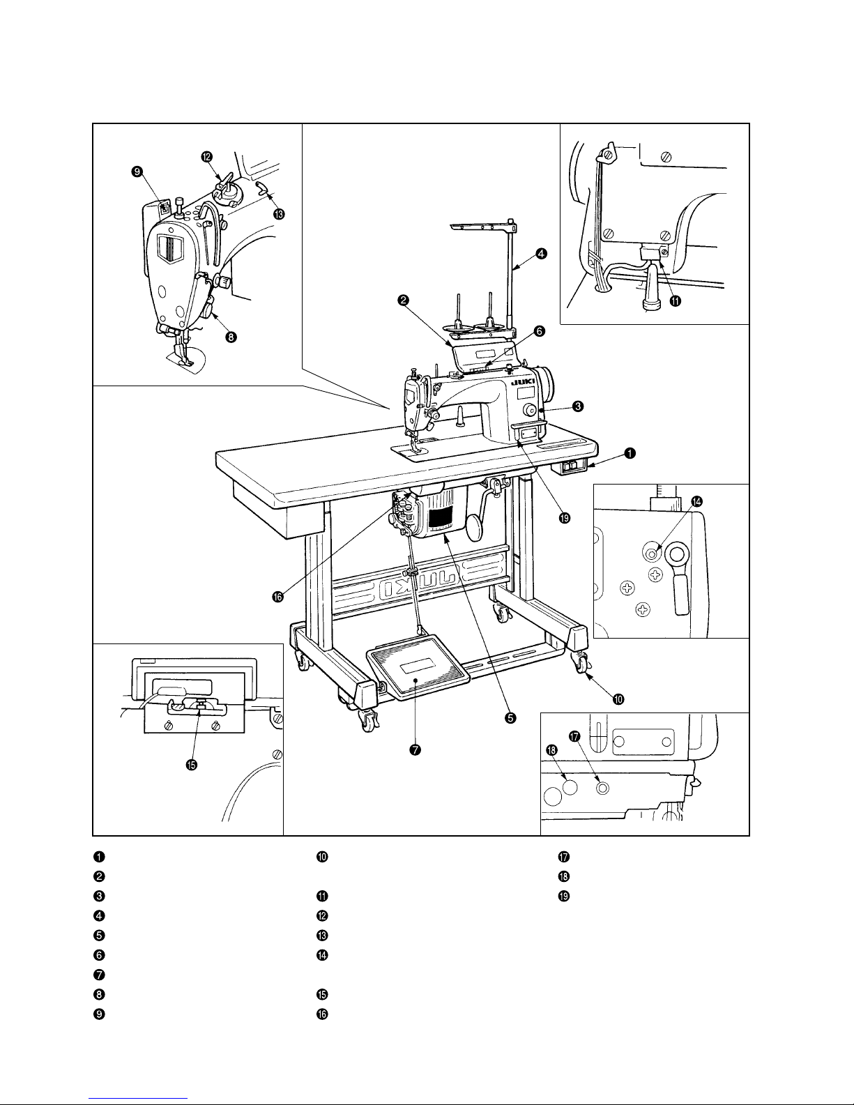
3. CONFIGURATION
(1)DDL-9000/SC-910
Power switch Screw for leveling table Oil inlet
Operation panel and stand (Caster) Air vent
Pulley cover Resistance pack Oil amount indicating
Thread stand Bobbin winder window (SS, SH)
PSC box (SC-910) Thread cutter retainer
Max. speed control knob Thread release changeover
Operation pedal screw
Touch-back switch Micro lifter screw
Wiper device Under cover
DDL-9000
– 3 –
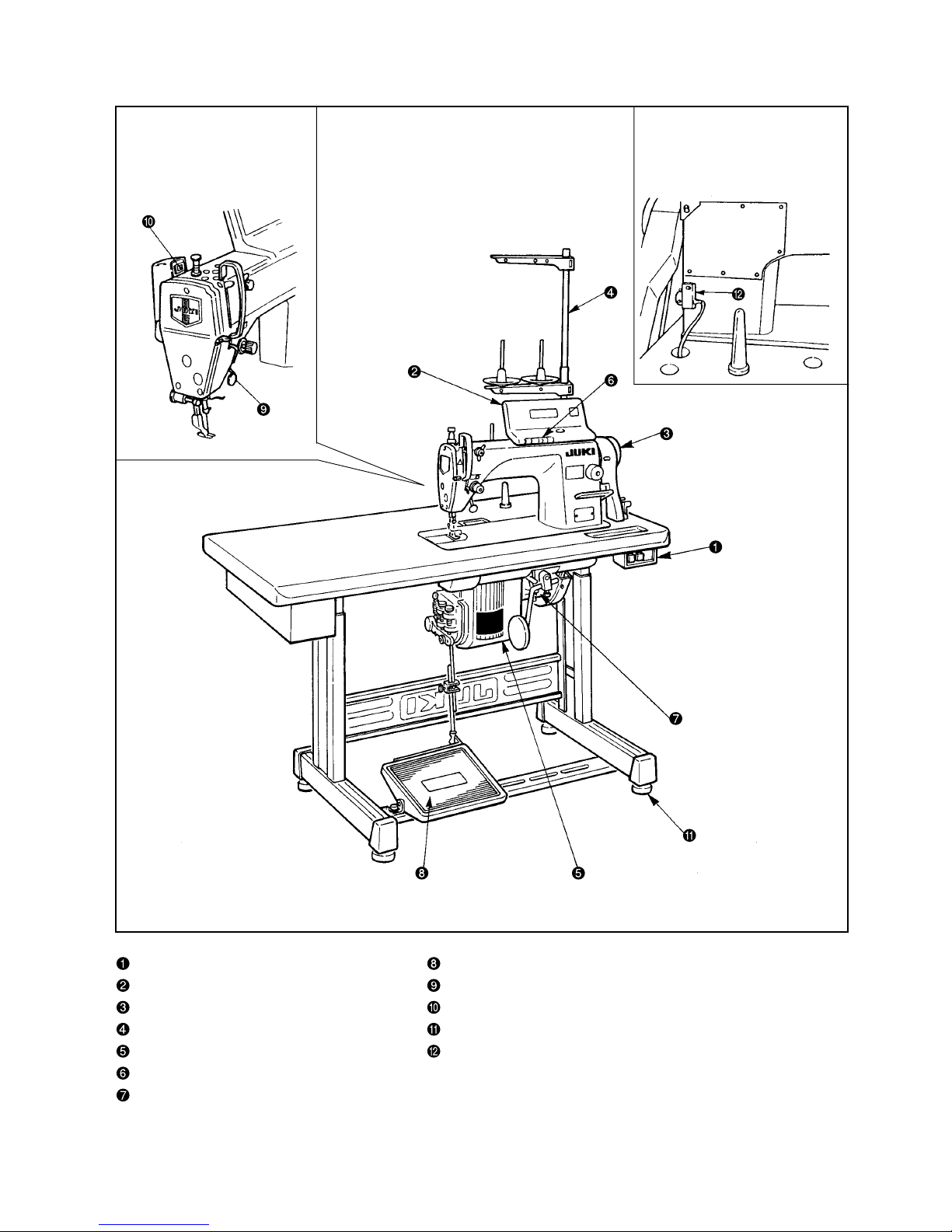
(2)DDL-8700/SC-910/M-91
Power switch Operation pedal
Control panel Touch-back switch
Synchronizer Thread wiping (wiper) device
L-shaped thread stand Screw or caster for level adjustment of table / stand
PSC box (SC-910) Resistor pack
Max. speed control knob
Motor (M-91)
– 4 –
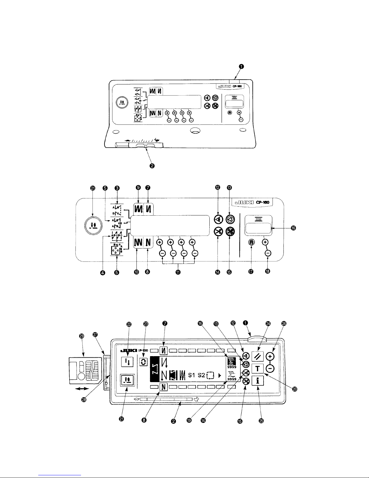
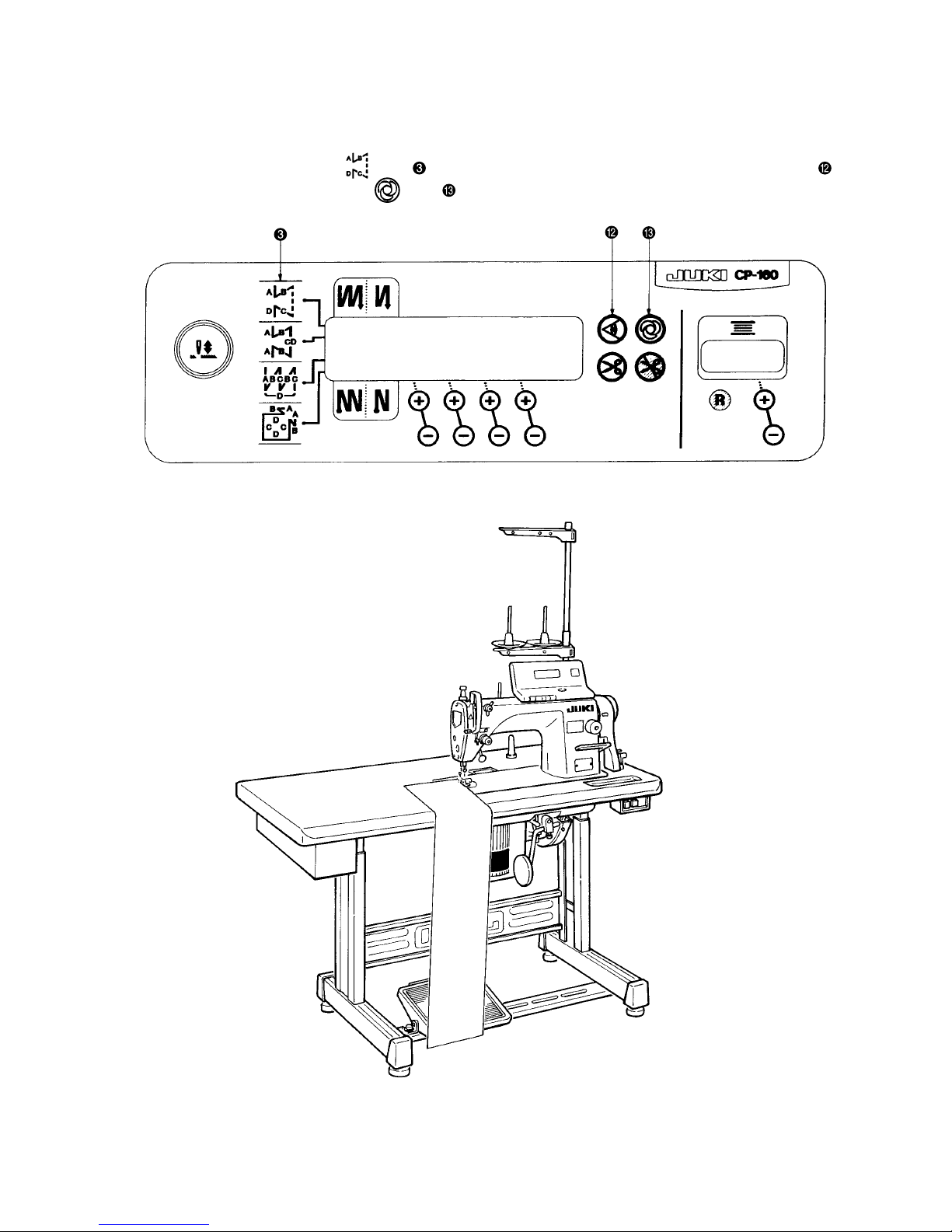
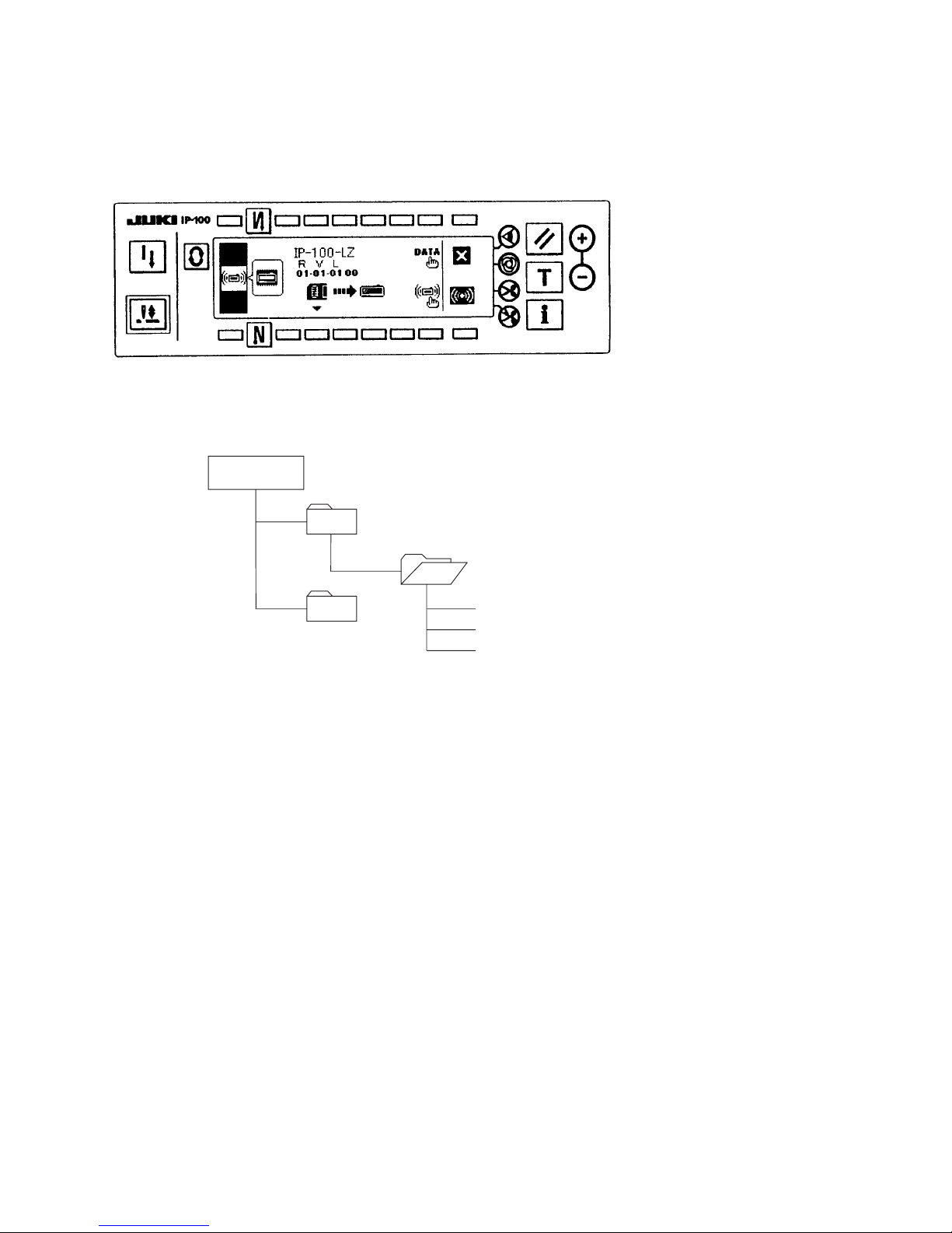
4. EXPLANATION OF CONTROL PANEL
(1) List of control panels of CP-160 and IP-100
CP-160
IP-100
– 5 –
No. Description
Power indication LED : Lights up when the power switch is turned ON.
<<
Max. speed limit variable resister : Maximum speed is limited when this resister is moved in the left
direction ( ).
Reverse stitching pattern switch : Used for specifying the reverse stitching pattern to be sewn.
<
Overlapped stitching pattern switch : Used for specifying the overlapped stitching pattern to be sewn.
<
Constand dimension stitching pattern switch : Used for specifying the constant dimension stitching
pattern to be sewn.
Rectangular stitching pattern switch : Used for specifying the rectangular stitching pattern to be sewn.
<
Automatic reverse stitching at the start of sewing switch : Used for turning ON / OFF the automatic
reverse stitching at the start of sewing.
Automatic reverse stitching at the end of sewing switch : Used for turning ON / OFF the automatic
reverse stitching at the end of sewing.
Automatic double reverse stitching at the start of sewing switch : Used for turning ON / OFF the
automatic double reverse stitching at the start of sewing.
Automatic double reverse stitching at the end of sewing switch : Used for turning ON / OFF the
automatic double reverse stitching at the end of sewing.
Switches for setting the number of stitches : Used for setting the number of stitches to be sewn in
processes A through D.
Material edge sensor ON / OFF switch : Rendered effective when the material edge sensor is
installed on the machine. Used for selecting whether or not the material sensor is used during sewing.
One-shot automatic stitching switch : Start the sewing machine with this switch, and the sewing machine
will run automatically until the material edge is detected or the end of the set number of stitches is reached.
Automatic thread trimming switch : When the material edge is detected, the machine will perform
thread trimming even when keeping depressing the front part of the pedal.
Thread trimming prohibition switch : Used for prohibiting thread trimming at any occasion.
<<
Bobbin thread counter : Indicates the amount of bobbin thread while counting it by subtracting from the set
value. When the bobbin thread remaining amount detecting device is installed on the machine, the counter
<<
indicates the number of times of detecting.
Bobbin counter reset switch : Used for returning the value shown on the bobbin thread counter to
the initial value.
Bobbin thread amount setting switch : Used for setting the amount of bobbin thread.
<
No. of pcs. counter : The indication shown on the counter increases while counting up the number of
finished pieces of garment every time the machine performs thread trimming.
Teaching switch : Used for setting the number of stitches to a value which has been actually sewn.
<
Needle up/down compensating switch : Used when performing needle up / down compensating stitching.
<<
Re-sewing switch : If the bobbin thread runs out before the completion of the operation steps of a
programmed stitching pattern, this switch is used for re-starting stitching from the position where the
<
stitching has been interrupted after replacing the bobbin.
Screen changeover switch : This is the switch to change over the screen.
<
Reset switch : This is the switch to make the value of bobbin thread counter or sewing counter the set value.
<
Information switch : This is the switch to perform various function settings.
<
Counter value setting switch : This is the switch to set the value of bobbin thread counter or No. of pcs. counter.
<
Smart media cover : This is the cover for smart media inserting opening.
<
Smart media slot (Smart media inserting opening) : To set smart media, insert smart media into
smart media slot and push it until it is almost hidden.
Smart media : ( Optional : Part No.HX005750000 )
<
CP160
IP-
100
<<
<
<<
<<
<
<
<
<<
<<
<<
<
<
<
– 6 –
(2) Explanation of control panel CP-160
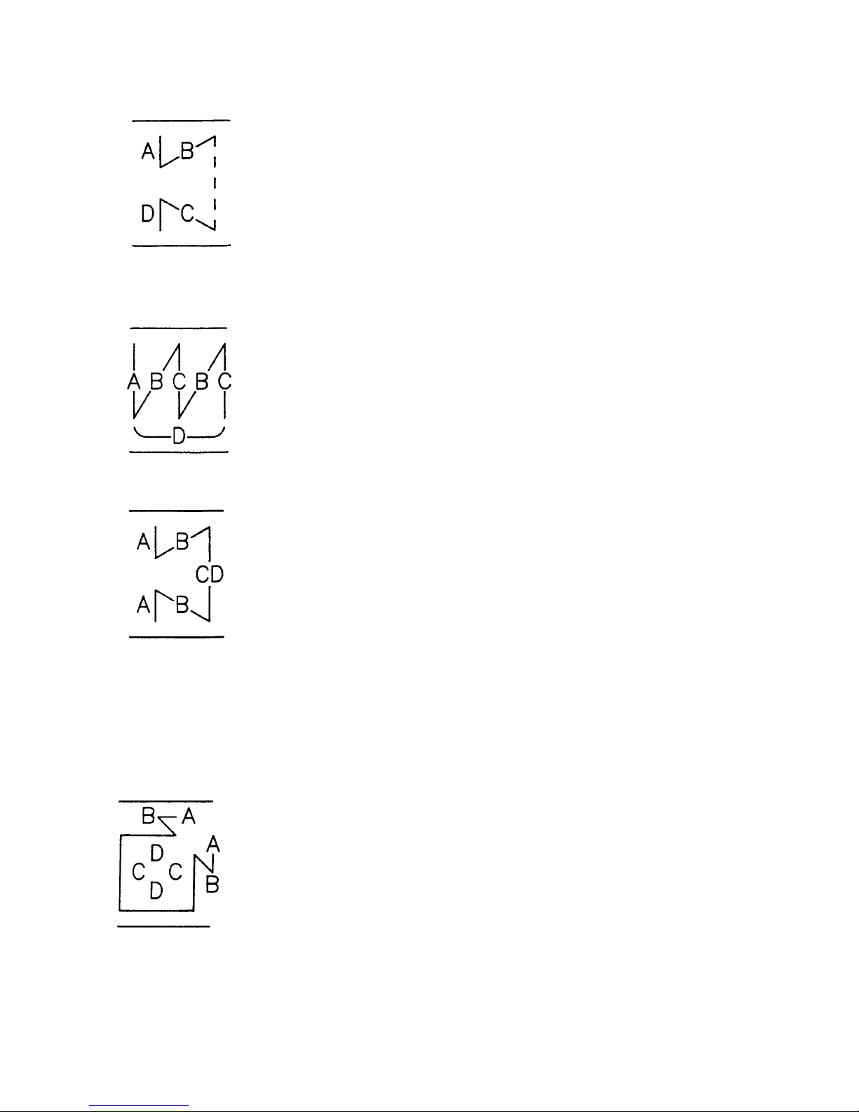
1) Reverse stitching pattern
When the sewing machine performs the free stitching operation, the
machine performs the reverse stitching operation at the start and end of
sewing.
The reverse stitching operation can set the ON and OFF settings.
Furthermore, single and double reverse stitching patterns can be selected.
Setting of number of stitches or other settings can be performed by operating the control panel.
A, B, C and D = 0 to 19 stitches
2) Overlapped stitching pattern
The sewing machine repeats the normal stitching and reverse stitching
by the predetermined time, and performs the line bartacking. Then, the
machine makes the thread trimmer actuate and stop to complete the
overlapped stitching procedure.
Change of the number of stitches or the number of times of repetition can
be performed by operating the control panel.
A, B and C = 0 to 19 stitches
D = 0 to 9 times
3) Constant-dimension stitching pattern
The free stitching process in the reverse stitching pattern becomes the
set value of the number of stitches. The sewing machine will automatically
stop (automatically perform thread trimming if the automatic thread
trimming is selected.) after the machine finishes the predetermined number
of stitches in the process of CD.
If the automatic thread trimming is not selected, operate the touch-back
switch after the machine has automatically stopped. Then, the machine
runs at a low speed (stitch compensation operation). Also, if the pedal is
returned to its neutral position and depressed its front part again, the
sewing can be continued regardless of the setting of number of stitches.
Setting of number of stitches or selection of automatic thread trimming
can be performed by operating the control panel.
A and B = 0 to 19 stitches CD = 0 to 500 stitches
4) Rectangular stitching pattern
There are 4 operation steps in the process of constant-dimension stitching
pattern. At each operation step the sewing machine automatically stops
after sewing the predetermined number of stitches. At this time, if the
touch-back switch is operated, the sewing machine runs at a low speed
(stitch compensation operation). Also, in case of the last operation step, if
the pedal is returned to its neutral position and depressed its front part
again, the sewing can be continued regardless of the setting of number of
stitches. However, if the automatic thread trimming is set, the machine
will perform thread trimming. Setting of number of stitches or selection of
automatic thread trimming can be performed by operating the control panel.
A and B = 0 to 19 stitches C and D = 0 to 99 stitches
– 7 –
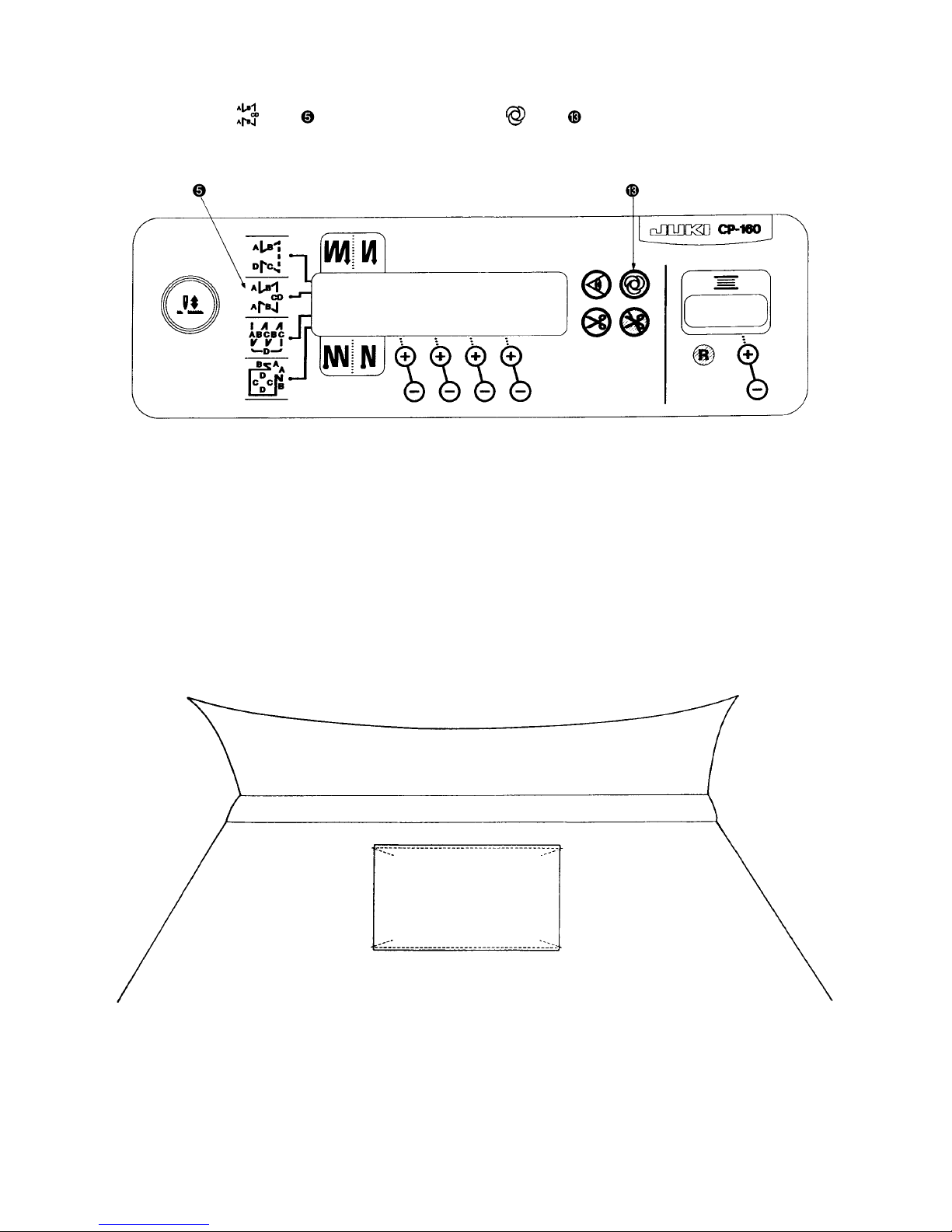
(3) Example of application
1) When the CP-160 is used together with the material end sensor (ED : optional), it can be used as a
small edge-controller.
(Method) Adjust the position to mark of the CP-160, turn ON material end sensor ON/OFF switch of
the CP-160, and turn ON mark of the automatic one-shot stitching.
Caution) Number of rotations of the automatic one-shot stitchig can be changed by the function setting
(No. 38).
– 8 –
2) Label attaching is performed by the automatic one-shot stitching with the CP-160
(Method) Select mark on the CP-160, and turn ON mark of the automatic one-shot stitching.
Explanation) Number of stitches at the section CD can be set up to 500 stitches. If the stitch length is 2 mm, it is
possible to sew approximately 1,000 mm (1 m).
This function can perform the automatic one-shot stitching without using the material end sensor
(ED : optional). Therefore, the sewing machine performs the sewing to the last according to the
sewing pattern even if the label is not located at the end of material when the pedal is depressed
once.
Label
CD
CD
– 9 –
Condition Machine head of DDL-8700H (for thick materials)
Stitch length 4 mm
Number of stitches 4 stitches
ITEM No. 64 “0” rpm
Standard
Condition Machine head of DDL-8700H (for thick materials)
Stitch length 4 mm
Number of stitches 4 stitches
ITEM No. 64 170rpm
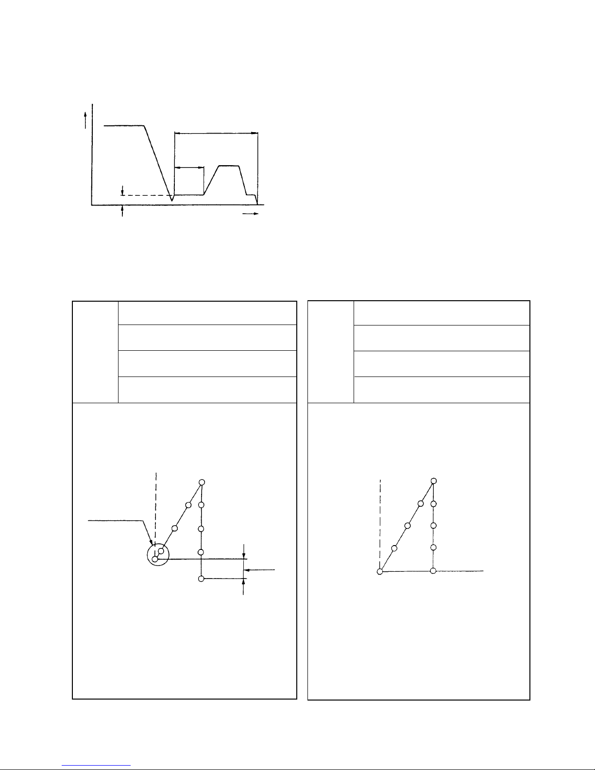
3) Seam joining of the reverse feed stitching at the end of sewing (For thick materials)
Especially some sewing machine heads for thick materials are likely to fail joining the seam at the section of the
following figure even if the timing of reverse feed stitching at the end of sewing is compensated.
1 At the timing to move to the reverse feed stitching action,
the rotating speed at the section where the sewing machine
is rotated at a low speed can be changed.
SC-910 function setting No. 64
(0 to 250 rpm changeable : 200 rpm was fixed in the past.)
Example) Use for reference.
Section of EBT
Section of low
speed
Time
1
Speed
Stitch lenth
becomes small.
Stitch
length
slips off.
– 10 –
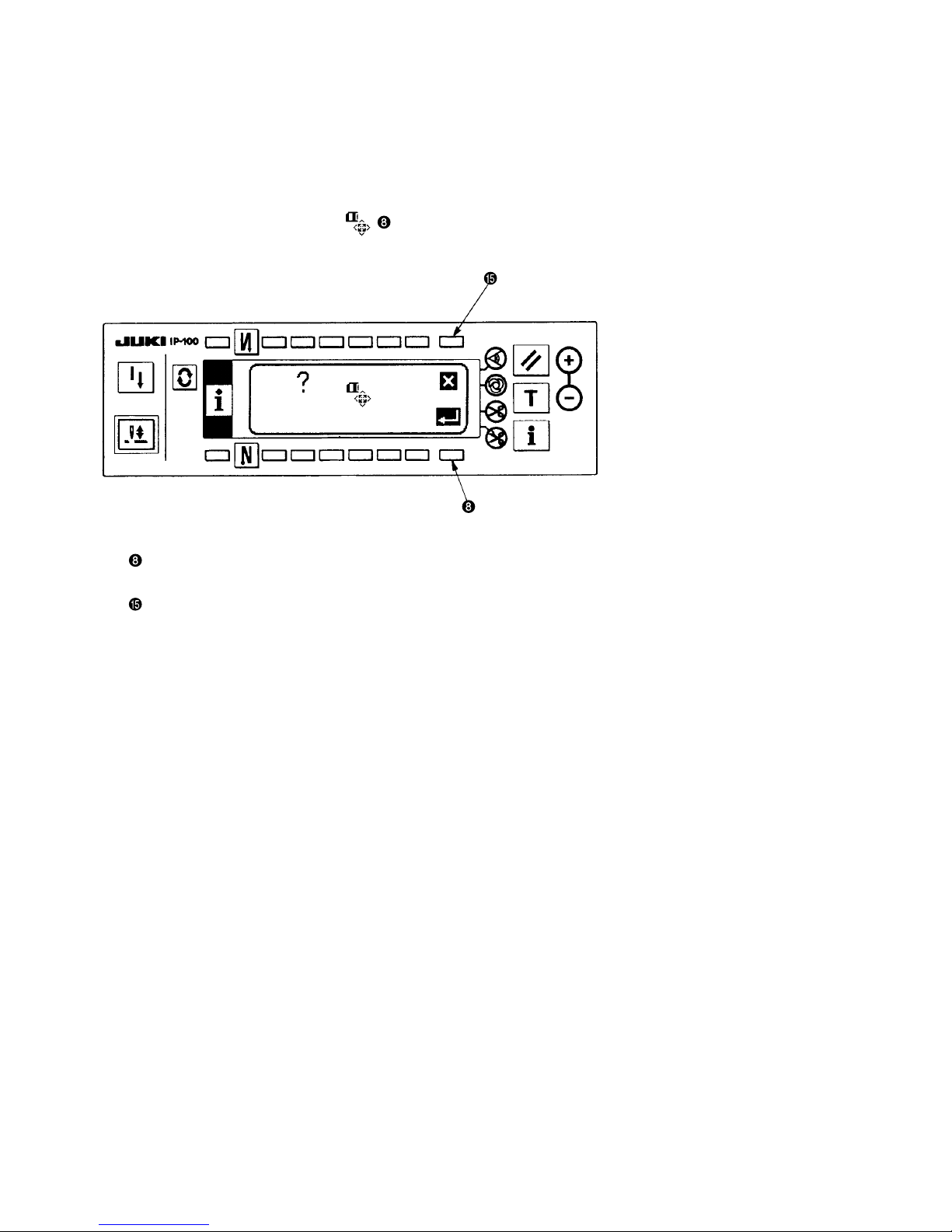
(4)Explanation of control panel IP-100
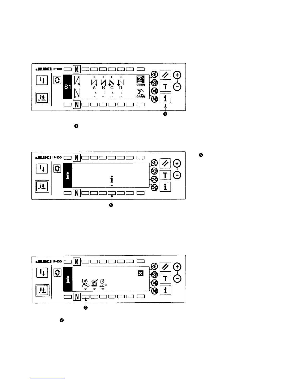
1) Information
Setting and checking of various data can be performed with the information.
For the information, there are the operator level and the maintenance personnel level.
[Operator level]
1) Turn ON the power.
2) Press switch to display the information screen.
Information screen (operator level)
1. Sewing management information
For the sewing management information, there are the maintenance management function, production control
function and working measurement function.
[Maintenance management function]
: Sewing management
information
1) Press to display the maintenance function screen.
– 11 –
Information screen (Maintenance personnel level)
: Ver display
: Function setting
: Sewing management
information
: Communication mode
: Smart media format
[Maintenance personnel level]
1) Turn ON the power. When the needle bar is not in the UP position, turn the handwheel to bring the needle bar
to its UP position.
2) Press switch for approximately three seconds to display the information screen.
3) Press switches , , , and corresponding to the various functions.
2. Ver display
Software version of each CPU is displayed.
Press switch in the information screen (maintenance personnel level).
Ver display screen
Explanation of display
Others
Level
Version
Revision
Kind of CPU
01- 01 01 00
RVL
Panel software
Servo motor software

– 12 –
3. Sewing management information
For the sewing management information, there are the operator level and the maintenance personnel level.
[Operator level]
Press switch in the information screen.
[Maintenance personnel level]
Press switch for approximately three seconds in the information screen.
Pictograph on the left end of the sewing management information is shown in reverse video.
Sewing management information screen (Maintenance personnel level)
4. Operation status screen
The total record of the sewing machine is displayed.
: Total operation time of the sewing machine (hour)
: Total number of times of thread trimming of the sewing machine (number of times)
: Total current-carrying time of the sewing machine (hour)
: Total number of stitches of the sewing machine (1,000 stitches)
: Maintenance function
: Production control function
: Operation measurement
function
: Operation status
: Error record

– 13 –
5. Error record display
Press error record display switch in the sewing management information screen (maintenance personnel
level).
Error record screen
When switch or is pressed, the error record scrolls up or down.
Explanation of display
Error record of approximately 100 cases (depending on the memory capacity) can be stored in memory in the
order of the latest.
6. Communication mode
Uploading and downloading of various data with the sewing machine server utility (hereinafter called SU- 1) or
the smart media can be performed in the communication mode.
For the communication mode, there are the operator level and the maintenance personnel level.
The kind of data which can be handled with the operator level is different from that with the maintenance personnel level.
Kind of data Operation level Download Upload Extension Remarks
of file
Maintenance MSP
All sewing machine personnel
data
Panel Maintenance NG PRG
personnel
Main
Servo motor
Each program data
Communication function table
: Panel
: Smart media
: SU-1
Record No.
Error No.
ime occurred (Unit : time)
– 14 –
Operating procedure
[Maintenance personnel level]
Press communication mode switch for approximately three seconds in the information screen.
ictograph on the left end of the communication screen is shown in reverse video.
Communication screen (Maintenance personnel level)
7. Communication setting
1 Data selection
Press data selection switch in the communication screen.
Data selection screen
Select the data to perform communication, and press set key switch .
2 Communication method selection
Press communication method selection switch in the communication screen.
Communication method selection screen
Kind of selected data
Data selection
Data communication
source
Data
communication
destination
Communication
method selection
Start of
communication

– 15 –
Select the method to perform communication and press set key switch .
Reference : Communication method cannot be selected by downloading of program.
3 Data communication source
4 Data communication destination
Set data communication source and data communication destination in the ten key screen, or "+" or "–
" key.
(Ten key input, or "+" or "-" key input is changed according to the kind of data.)
5 Start of communication
After all settings have been completed, press communication start key switch to start communication.
When the screen returns to the communication setting screen after display of the during communication
screen, communication is completed.
(Caution) Never turn OFF the power during communication.
Motion in case of OFF cannot be guaranteed.
– 16 –
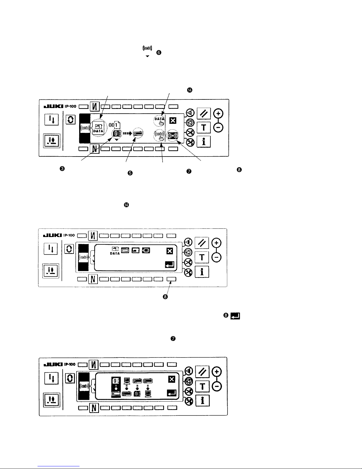
8. All sewing machine data
1. Data such as sewing setting data, adjustment data, etc. which are memorized in the sewing machine can be
stored in one package.
2. It is possible to download the all sewing machine data to the other sewing machines to make the same
setting.
Communication screen (Download of all sewing machine data)
Reference : When downloading the all sewing machine data, it is necessary that the file and the Ver of the sewing
machine have to agree with each other. An error occurs when the file of different Ver is downloaded.
(Caution) It is not possible to store and copy the function setting of the servo motor.
Folder structure of all sewing machine data (* .MSP) file in the smart media
Upload :
Uploading to the smart media is written in the folder of "SC910".
In case there is no folder, the folder of "SC910" is automatically created.
Download :
Downloading from the smart media is read from the folder of "SC910".
Store the copy from other media or the like in the folder of "SC910".
1 Create folder "SC910" in the smart media.
(It is not necessary to create the folder when it already exists.)
2 Copy the file (extension MSP).
Smart media
PROG
SC910
SC00001.EPD
SC00001. MSP
– 17 –
9. Program data
1. When the change of software occurs in the future due to Ver-up or the like, rewriting of the program can be
performed.Rewriting of the program is performed with each CPU.
Communication screen (Download of IP-100 program data)
Folder structure of program (* .PRG) file in the smart media
Download :
Downloading from the smart media is read from the folder of "PROG\SC910".
Store the copy from other media or the like in the folder of "PROG\SC910".
1 Create folder "PROG" in the smart media.
2 Create folder "SC910" in the PROG folder.
(It is not necessary to create the folder when it already exists.)
3 Copy the program file (extension PRG).
Smart media
PROG
SC910
SC910
IP010101.PRG
MT010101.PRG
– 18 –
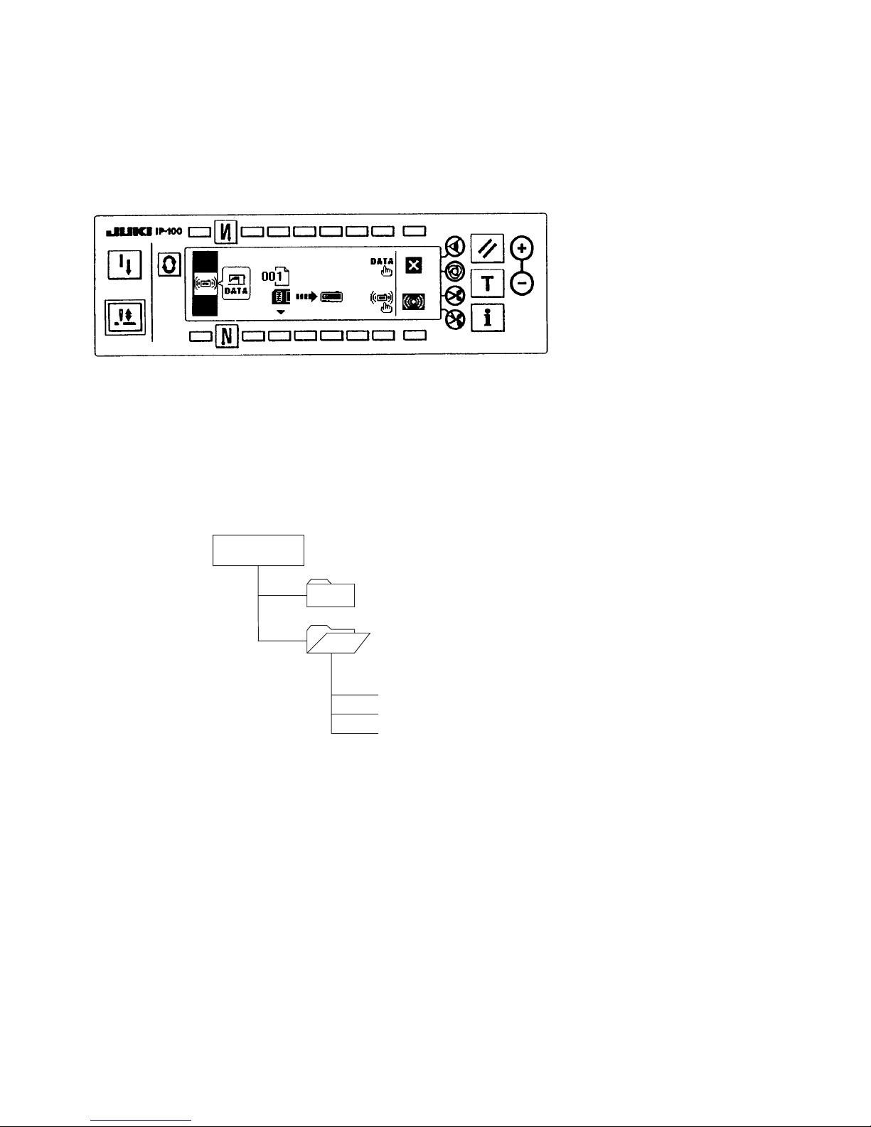
10. Smart media format
Perform formating of the smart media.
The media formated with the personal computer or the like may not be used.
When using the media with IP-100, be sure to perform formating with IP-100.
Press smart media format switch in the information screen (maintenance personnel level)
Smart media format confirmation screen
: Formating is performed.
Confirm again whether formating can be performed before pressing the switch.
: The screen returns to the information screen.
(Caution)When formating is performed, all data stored in the smart media are deleted. Take the backup
of necessary data beforehand.

– 19 –
2) Matters that demand special attention regarding the operation panel, IP-100
1. Kind of IP-100
For the operation panel, IP-100, there are several kinds of types in accordance with the specifications.
Types that can be used for SC-910 are TYPE-B and TYPE-C. The product is TYPE B0A or TYPE C0A which is
indicated on the name plate seal located in the rear of the panel case.
Brackets for installing panel for both types are different from each other.
There is the jumper wire W1 (side of RVR1 variable resistor) on the circuit board. Set the W1 setting to 2-3 for
both types.
Type name plate seal Setting of W1
TYPE B0A 2-3 pin setting (lower side)
TYPE C0A 2-3 pin setting (lower side)
(Caution) When setting is wrong, LCD screen display is not properly performed.
2. Matters that demand special attention when disassembling the operation panel
Operation panel, IP-100 is constructed with precision components.
Leave the action such as disassembling the panel case or the like to our service department since injury by
electric shock or failure of panel will be caused.
If the force more than expected is applied when disassembling the panel case, it may be damaged since it is
made of the plastic molding.
Especially when performing disassembling (opening/closing) the front panel and the rear panel in the state that
the smart media cover attached to the rear case is closed, the small-sized switch mounted on the inside of the
printed circuit board interferes with the smart media cover and may be damaged. So, be careful.
It is necessary to assemble all screws used in the operation panel with tightening torque of 0.56Ncm.
(Excluding screws to fix it on the machine head and to fix the earth wire.)
3. Prohibition of the change of DIP switch setting
Do not perform the changeover of DIP switches since the guarantee of control program and stored data cannot
be performed.
It is not necessary to operate these switches since they are all changeover switches for the production by the
manufacturers.
(Caution) The 4-string DIP switches are not exposed unless the operation panel case is disassembled.
W1
1
2
3
TYPE B0A, C0A

– 20 –
3) Error Display
1. Error display
* Error is informed by means of the panel display, machine head mirror LED blink and control box
buzzer.
Two different kinds of screens of the panel display screen appear due to the difference of the procedures.
1. Error screen disappears when the operator
removes the cause.
Example) The needle position is not in its UP
position.
Make the needle position UP by turning the
handwheel by hand.
2. Remove the cause of error after turning OFF
the power.

– 21 –
4) Error code list (Error display in panel)
There are the following error codes in this device. These error codes interlock (or limit function) and inform the
problem so that the problem is not enlarged when any problem is discovered. When you request our service, please
confirm the error codes.
— UP position detection error when turn- 1.When needle position is not UP position at the 1. Set to UP position by turning handwheel by hand.
ing ON the power time of turning ON the power. 2. Connect synchronizer connector.
— Smart media cover open 1. Lid of smart media slot is open. Close the lid.
E000 EEPROM initialization 1. EEPROM initialization is executed. —
2. Resistor pack is replaced.
E003 Disconnection of synchronizer connector 1. When position detection signal is not inputted from 1. Check the synchronizer connector (CN30) for loose connection and disconnection.
the sewing machine head synchronizer.2.Check whether the synchronizer cord has broken since the cord is caught in the
2. When the synchronizer has broken. machine head or the like.
E005 Synchronizer upper position sensor failure
E007 Overload of motor 1. When the machine head is locked. 1. Check whether the thread has been entangled in the motor pulley.
2. When sewing extra-heavy material beyond the 2. Check the motor output connector (4P) for loose connection and disconnection.
guarantee of the machine head.
3. When the motor does not run.
E008 Undefined machine head When the machine head connector is not properly read. Check the machine head connector (CN31) for loose connection and disconnection.
E011 Smart media not inserted Smart media is not inserted. Return after reset operation.
E012 Read error Data read from smart media is not possible. Return after reset operation.
E013 Write error Data write to smart media is not possible. Return after reset operation.
E014 Write protect Smart media is in write prohibition state. Return after reset operation.
E015 Format error Formatting cannot be performed. Return after reset operation.
E016 External media capacity over Media capacity of smart media is short. Return after reset operation.
E019 File size over File is too big. Return after reset operation.
E021 Access error Abnormality of access of file Return after reset operation.
E302 Fall detection switch failure When fall detection switch is inputted in the state that 1. Check whether the machine head is tilted without turning OFF the power switch (sewing
the power is turned ON. machine operation is prohibited for safety sake).
2. Check whether the fall detection switch cord is caught in the sewing machine or the like
and has broken.
E343 Bobbin thread remaining amount sensor 1. The device is not connected when bobbin thread 1. Check whether the device is connected.
unit trouble remaining detection function is ON. 2. Check whether bobbin thread remaining amount detection connector (CN58) is loosened
2. Failure of position sensor of the device or disconnected.
3. Failure of position solenoid of the device
E730 Motor encoder trouble (AB phase) When the motor signal is not properly inputted. 1. Check the motor signal connector (CN38 and CN39) for loose connection and
disconnection.
2.
Check whether the motor signal cord has broken since the cord is caught in the machine head
or the like.broken since the cord is caught in the machine head or the like.
E733 Reverse rotation of main shaft motor State that the sewing machine is rotating in the Turn OFF the power.
different direction from the normal rotating direction
at 500 rpm or more continues 40 times or more while
motor is running (excluding holding of needle
position).
No. Description of error detected Cause Item to be checked or corrective measure
E004 Synchronizer upper position sensor failure
E731 Motor sensor error (UVW phase)

– 22 –
E810 Solenoid short-circuit When the short-circuited solenoid is desired to be driven. Check whether the solenoid is short-circuited.
E811 Overvoltage 1. When voltage upper than guaranteed one is 1. Check whether the applied power voltage is higher than the rated voltage + (plus)
inputted. 10% or more.
2. When 200V is inputted for 100V setting. 2. Check whether 100V/200V changeover connector is set by mistake.
In the above cases, POWER circuit board has broken.
E813 Low voltage 1. When voltage lower than guaranteed one is 1. Check whether the votage is lower than the rated voltagw - (minus) 10% or less.
inputted. 2. Check whether 100V/200V changeover connector is set by mistake.
2. When 100V is inputted for 200V setting.
E920 GA failure Abnormality of gate array When return is not performed even after turning OFF the power, the possibility of gate
array breakage is large.
E922 Main shaft motor control is impossible. When main shaft motor cannot be controlled. Turn OFF the power.
E924 Motor driver failure Motor driver has broken. Turn OFF the power.
E940 Bird's nest sequence error Bird's nest prevention sequence is not completed. Turn OFF the power.
E941 GA failure Abnormality of gate array When return is not performed even after turning OFF the power, the possibility of gate
array breakage is large.
E942 EEPROM failure Writing is not completed even after the lapse of 10 Turn OFF the power.
[ms] or more.
E944 Left needle is uncontrollable. In case of LH sewing machine with organized split Check whether needle control connectors (CN55 and CN56) are loosened or discon
needle bar mechanism nected.
1. Same error is not detected yet.
2. Home position signal is ON when left needle is
locked.
3. Home position signal is OFF when left needle is
released.
E945 Right needle is uncontrollable. In case of LH sewing machine with organized split Check whether needle control connectors (CN55 and CN56) are loosened or discon
needle bar mechanism nected.
1. Same error is not detected yet.
2. Home position signal is ON when right needle is
locked.
3. Home position signal is OFF when right needle is
released.
No. Description of error detected Cause Item to be checked or corrective measure

– 23 –
5) Warning list
No. Contents and display of warning Corrective measure Remarks
A201 Replacement of oil warning • Press to close warning screen, and Refer to
perform replacement of needle. Then clear Instruction Manual
the value in the clear screen. 6-15-(2) Sewing
•Press to clear the value, and perform management
replacement of needle. information.
A202 Cleaning warning • Press to close warning screen, and Refer to
perform cleaning. Then clear the value in the Instruction Manual
clear screen. 6-15-(2) Sewing
•Press to clear the value, and perform management
cleaning. information.
A203 Replacement of needle warning • Press to close warning screen, and Refer to
perform replacement of oil. Then clear the Instruction Manual
value in the clear screen. 6-15-(2) Sewing
•Press to clear the value, and perform management
replacement of oil. information.

– 24 –
5. CONTROL BOX (SC-910/SC-910A)
(1)Connecting the cords
WARNING :
•To prevent personal injury caused by abrupt start of the sewing machine, carry out the work after turning OFF the
power switch and a lapse of 5 minutes or more.
•To prevent damage of device caused by maloperation and wrong specifications, be sure to connect all the corresponding connectors to the specified places.
•To prevent personal injury caused by maloperation, be sure to lock the connector with lock.
• As for the details of handling respective devices, read carefully the Instruction Manuals supplied
with the devices before handling the devices
Following connectors are prepared on the front face of SC-910. Connect the connectors coming from the machine
head to the corresponding places so as to fit the devices mounted on the machine head.
Optional unit A
IO circuit board A (asm.)
CN30 Synchronizer : it detects the needle bar position.
CN35 CP-160 panel : V arious kinds of programmed sew-
ing can be executed.
(Refer to the Instruction Manual for each
CN33 Not used
CN31 Machine head connector 4P
CN42 External input/output connector : input/output of
up/down detection signal, rotation
prohibition signal, etc. is prepared.
CN48 Safety switch (standard) : When tilting the sewing
machine without turning the power
OFF, the op-
eration of the sewing machine is
prohibited so as
to protect against danger.
Optional switch : by changing over the
internal
functions, 6 kinds of functions can
be selected.
CN40 Presser foot lifter solenoid. (For automatic presser
foot lifter type only)
CN46 Machine head solenid : Thread trimming, reverse-
stitching solenoid, touch-back switch, etc.
CN47 Optional circuit board connection connector : Re-
quired when using JUKI standard bobbin thread
remaining amount detection sensor, etc.
CN38, CN39
Motor signal connector
CN32 Standing machine pedal : JUKI standard PK-70,
etc. Sewing machine can be controlled with the
external signal.
CN34 IP-100 panel (LCD panel) : Various kinds of pro-
grammed sewing can be executed.
CN45 Material end detection sensor ED-4, etc.
CN43 Fan
* By adding the optional unit A, the following optional devices
of JUKI standard can be connected.
CN128 Left/right needle detection
CN127 Thread holding, thread suction, thread drawing
CN122 Needle cooler (bottom fan)
CN121 Bobbin thread remaining amount detection
CN120 +24V external power source
CN123 Needle/bobbin thread remaining amount detec-
tion sensor
CN125 External interface I/F D/A Input
CN126 Left/right lock SW, LED
CN129 Thread holding, thread suction, thread drawing,
bobbin thread remaining amount detection

– 25 –
Specified No.
Specified value
(2) Setting for functions
Functions can be selected and specified by means of the four setting switches and light emitting diode located
inside the front cover of the SC-910/SC-910A.
(Caution) • Do not perform switch operations other than those described in the following explanations.
• Be sure to re-turn the power switch ON after one second or more has passed. If the power is
turned ON immediately after turning it OFF, the sewing machine may not work normally. In
this case, turn ON the power again.
WARNING :
To avoid possible personal injuries caused by movement other than that you desired, do not operate the switches in the
procedure other than those required, as described below, to specify the functions.
How to change over to the function setting modo
1) Turn OFF the power to the unit.
2) Open the front cover.
3) Pressing switch , turn ON the power to the unit.
4) Indication will be shown on the display. (If the
indication fails to change, re-perform the procedures 1) to 3).
Switch for entering specified value changed and
updating setting No. in UP direction
Switch for entering specified value changed and
updating setting No. in DOWN direction
Up switch (UP)
Down switch (DOWN)

– 26 –
5) When you want to advance the setting No., press
switch to advance the setting No.
When you want to return the setting No., press
switch to return the setting No.
(Caution) Keep pressing switch or switch ,
and the setting No. will advance (return) continuously.
When the setting No. is advanced (returned), the contents which are before
by one (after by one) will be etemined.
So be careful when changing the Setting No.
EXAMPLE) CHANGING THE FLICKER REDUC-
ING FUNCTION (SETTING No. 5)
Press switch four times to set the setting No. to “5”.
Press switch five times to change the set No. to “5”
since the current set value is displayed on LED .
(Standard : “0”)
(Caution) Keep pressing switch or switch ,
and the setting vaue can be changed
continuously.
6) When the change has been completed, press
switch or to specify the changed value.
(Caution) 1. When turning OFF the power before
performing this work, the contents
which have been changed are not
updated.
2. Press switch , and screen display
will change to the contents of next
setting No.
3. Press switch , and screen display
will change to the contents of previous setting No.
After completing the operation, turn
OFF the power, and return the front
cover to the original position.
The machine returns to the normal
operation by turning ON the power
again.
Setting No.

– 27 –
(3)Function setting list
No. Item Description Setting range
1 Soft start The number of stitches to be sewn at a low speed when the soft-start 0 to 9 34
function function is used at the start of sewing. (Stitches)
0 : Soft-start function is not operative.
2 Material end Material end sensor function (used in case of without panel). 0/1 34
sensor 0 : Material end detection function is not operative
function 1 : After detecting material end, the specified number of stitches (No. 4) will
be sewn, and the sewing machine will stop.
3 Thread trimming Thread trimming function by material end sensor (used in case of without panel). 0/1 34
function by 0 : Automatic thread trimming function after detection of material end is not
material end operative.
sensor 1 : After detecting material end, the specified number of stitches (No. 4) will
be sewn, and the sewing machine will stop and perform automatic
thread trimming.
4 Number of Number of stitches for material end sensor (used in case of without panel). 0 to 19 34
stitches for Number of stitches from detection of material end to stop of the sewing (Stitches)
material end machine.
sensor
5 Flicker reducing Flicker reducing function (If the hand lamp flickers). 0 to 8 34
function 0 : Flicker reducing function is not operative.
1 : Less effective . 8 : Highly effective
6 Bobbin thread Bobbin thread counting function 0/1 34
counting 0 : Bobbin thread counting function is not operative.
function 1 : Bobbin thread counting function is operative.
7 Unit of bobbin Unit of bobbin thread counting down 0 to 2
thread counting 0 : Count/10 stitches
down 1 : Count/15 stitches
2 : Count/20 stitches
8 Number of Sewing speed of reverse feed stitching 180 to 3000
rotation of (r.p.m)
reverse feed
stitching
9 Thread Thread trimming prohibiting function (used in case of without panel). 0/1 34
trimming 0 :Thread trimming prohibiting function is not operative.
prohibiting 1 : Thread trimming is prohibited.
function (Output of solenoid is prohibited. : Thread trimmer and wiper)
10 Setting of Position of needle bar is specified when the sewing machine stops. 0/1 34
needle bar 0 : Predetermined lowest position
stop position 1 : Predetermined highest position
when the sewing
machine stops.
11 Click sound of Click sound of key switch mounted on PSC is specified. 0/1 34
key switch 0 : Click is not operative.
mounted on 1 : Click is operative.
PSC
12 Optinal switch Switching of function of optional switch. 0 to 8 35
function 0 : No function
selection 1 : Needle up/down compensating stitching
2 : Back compensating stitching
3 : Function of canceling once reverse feed stitching at the end of sewing
4 : Thread trimming function
5 : Presser foot lifting function
6 : One stitch compensating stitching
7 : Function of simultaneously canceling reverse feed stitching at the start
and end of sewing
8 : Neutral presser lifting changeover function
13 Function of Function of prohibiting start of the sewing machine by bobbin thread counting 0 to 2 43
prohibiting 0 : When counting is out (-1 or less) Function of prohibiting start of the
start of the sewing machine is not operative.
sewing 1 : When counting is out (-1 or less) Function of prohibiting start of the
machine by sewing machine is operative.
bobbin thread 2 : When counting is out (-1 or less) Function of forcibly prohibiting start of
counter the sewing machine is operative.
14
Sewing Counting function of sewing (number of completion of process)
0/1
35
counter 0 : Sewing counter function is not operative.
1 : Sewing counter function is operative.
15
Number of times Number of times of detection of run-out of bobbin thread remaining amount
0 to 19
of detection of 0 : Function of bobbin thread remaining amount is not operative.
run-out of 1 to 19 : Number of times during which the signal is not made even if run-out
bobbin thread of bobbin thread remaining amount is detected.
remaining
amount
1
0
2
0
3
0
4
5
5
0
6
1
7
0
8
1900
9
0
10
0
11
1
12
0
13
0
14
0
15
1
Indication of Ref.
function setting page

– 28 –
No. Item Description Setting range
18 Bird’s nest This function is effective in combination with the machine head with bird's nest 0 to 2 35
prevention prevention function (optional unit A is necessary).
function 0 : Bird's nest prevention function is not operative.
1 : Bird's nest prevention function is operative.
2 : Bird's nest prevention function is operative.(with tension release)
19 Needle thread This function is effective in combination with the machine head with bird's nest 0 to 1 35
release prevention function (optional unit A is necessary).
function at the 0 : Needle thread release function is not operative.
sewing start 1 : Needle thread release function is operative.
20 Number of This function is effective in combination with the machine head with bird's nest 0 : Function 35
condensation prevention function (optional unit A is necessary). OFF
stitches 0 : Condensation function is not operative. 1 to 9 stitches
1 to 9 : Number of condensation stitches
21 Function of Function of lifting presser foot when the pedal is in neutral position. 0/1 35
neutral 0 : Function of neutral automatic presser lifting is not operative.
presser lifting 1 : Selection of function of neutral presser lifting.
22 Function of Function of needle up/down compensating switch on the operation panel can 0/1 35
changeover of be changed.
compensating 0 : Needle up/down compensation
switch on the 1 : One stitch compensation
operation
panel function
24 Function of fine Number of rotation can be compensated. -1.5% to 1.5% 43
adjustment of Be sure to normally use this function with "0". (0.1%)
number of
rotation
25 Thread trimming This function sets the thread trimming motion after DOWN position has been 0/1 36
motion condition off by turning handwheel by hand.
0 : Thread trimming after turning handwheel by hand is permitted.
1 : Thread trimming after turning handwheel by hand is prohibited.
26 Function of This function prevents the sewing machine from the reverse rotation after it 0 to 9 36
setting the has stopped.
holding force 0 : Initial value
after stop 1 : Less effective -> 9 : Highly effective
27 Function of This function sets the magnitude of return force of the needle bar before the 1 to 100 36
setting the retry motion.
reaction force 1 : Less return force -> 100 : High return force
at the time of
retry
28 Number of This function is effective in combination with the machine head with bird's nest 0 to 30 36
stitches of prevention function (optional unit A is necessary). (Stitches)
needle thread This function sets the number of stitches grasping thread at the sewing start.
release 0 to 30 stitches
29 Suction time of This function sets the suction motion time of the back-tack solenoid. 50 to 300 36
the first start of 50 ms to 300 ms (ms)
the back
solenoid
30 Function of Function of reverse feed stitching on the way 0/1 37
reverse feed 0 : Function of reverse stitching on the way is not operative.
stitching on 1 : Function of reverse feed stitching on the way is operative.
the way
31 Number of Number of stitches of reverse feed stitching on the way. 0 to 19 37
stitches of (Stitches)
reverse feed
stitching on
the way
32 Effective condition Effective condition of reverse feed stitching on the way 0/1 37
of reverse feed 0 : Function is not operative when the sewing machine stops.
stitching on the 1 : Function is operative when the sewing machine stops.
way when the
sewing machine
is stopping.
33 Thread trimming Thread trimming function by reverse feed stitching on the way 0/1 37
function by 0 : Automatic thread trimming function after completion of reverse feed
reverse feed stitching on the way is not operative.
stitching on 1 : Automatic thread trimming after completion of reverse feed stitching on
the way the way is performed.
35 Number of Lowest speed by pedal 20 to 400 43
rotation at a (r.p.m.)
low speed
36 Number of Thread trimming speed 20 to 250
rotation of (Caution) Do not change the set value. (r.p.m.)
thread When it is changed, the sewing machine is apt to be broken.
trimming
18
1
19
0
20
0
21
0
22
0
24
0
25
1
26
0
27
50
28
1
29
250
30
0
31
4
32
0
33
0
35
200
Indication of Ref.
function setting page
36
210

– 29 –
37 Number of Sewing speed at the start of sewing (soft-start) 150 to 5500 34
rotation of (r.p.m.)
soft-start
38 One-shot One-shot speed (The max. value depends on the number of rotation of the 200 to MAX 37
speed sewing machine head.) (r.p.m.)
39 Pedal stroke at Position where the sewing machine starts rotating from pedal neutral position 1.0 to 5.0 38
the start of (Pedal stroke) (0.1mm)
rotation
40 Low speed Position where the sewing machine starts accelerating from pedal neutral 1.0 to 10.0 38
section of position (0.1mm)
pedal (Pedal stroke)
41 Starting position Position where the cloth presser starts lifting from pedal neutral position
-6.0 to 5.0 38
of lifting presser (Pedal stroke) (0.1mm)
foot by pedal
42 Starting position Starting position of lowering presser foot 0.8 to 5.0 38
of lowering Stroke from the neutral position (0.1mm)
presser foot
43 Pedal stroke 2 Position 2 where the thread trimming starts from pedal neutral position (When
-6.0 to -1.0 38
for starting the function of lifting presser foot by pedal is provided.) (Pedal stroke) (0.1mm)
thread trimming
44 Pedal stroke for Position where the sewing machin reaches its highest sewing speed from 1.0 to 15.0 39
reaching the pedal neutral position (Pedal stroke) (0.1mm)
maximum number
of rotation
45 Compensation Compensation value of the pedal sensor -15 to 15 39
of neutral point
of the pedal
46 Auto-lifter Auto-lifter selection 0/1
selecting 0 : Solenoid drive system
function 1 : Pneumatic drive system
47 Holding time of Limitation time of waiting for lifting solenoid type auto-lifter device 10 to 600 39
lifting auto-lifter (second)
48 Pedal stroke 1 Position where thread trimming starts from pedal neutral position (Standard -6.0 to -1.0 39
for starting pedal) (Pedal stroke) (0.1mm)
thread trimming
49 Lowering time Lowering time of presser foot after the pedal has been depressed. 0 to 250 41
of presser foot (Start of rotation of the sewing machine is delayed during this time.) (10ms)
51 Compensation Compensation of starting the solenoid for reverse feed stitching when reverse -36 to 36 39
of solenoid-on feed stitching at the start of sewing is performed. (10°)
timing of reverse
feed stitching at
the start of sewing
52 Compensation Compensation of releasing the solenoid for reverse feed stitching when reverse -36 to 36 39
of solenoid-off feed stitching at the start of sewing is performed. (10°)
timing of reverse
feed stitching at
the start of sewing
53 Compensation Compensation of releasing the solenoid for reverse feed stitching when reverse -36 to 36 40
of solenoid-off feed stitching at the end of sewing is performed. (10°)
timing of reverse
feed stitching at
the end of sewing
55 Foot lift after Function of lifting presser foot at the time of (after) thread trimming 0/1 40
thread trimming 0 : Not provided with the function of lifting presser foot after thread trimming
1 : Provided with the function of lifting presser foot automatically after thread
trimming
No. Item Description Setting range
37
800
38
2500
39
30
40
60
41
-21
42
10
43
-51
44
150
45
0
46
0
47
60
48
-35
49
140
51
-6
52
-4
53
-9
55
1
Indication of Ref.
function setting page

– 30 –
No. Item Description Setting range
56 Reverse Function of reverse revolution to lift the needle at the time of (after) thread 0/1 40
revolution to lift trimming
the needle after 0 : Not provided with the function of reverse revolution to lift the needle
thread trimming after thread trimming
1 : Provided with the function of reverse revolution to lift the needle after
thread trimming
57 Bobbin thread Function of detecting bobbin thread remaining amount at the time of (after 0/1 40
remaining thread trimming
amount 0 : Not provided with the function of detecting bobbin thread remaining
detection amount
function 1 : Provided with the function of detecting bobbin thread remaining amount
58 Function of Function of holding predetermined upper/lower position of the needle bar 0/1 40
holding 0 : Not provided with the function of holding predetermined upper/lower
predetermined position of the needle bar
upper/lower 1 : Provided with the function of holding predetermined upper/lower position
position of the of the needle bar
needle bar
59 Function of This function can specify the sewing speed of reverse feed stitching at the start 0/1 40
Auto/Manual of sewing.
change-over of 0 : The speed will depend on the manual operation by pedal, etc.
reverse feed 1 : The speed will depend on the specified reverse feed stitching speed
stitching at the (No. 8).
start of sewing
60 Function of stop Function at the time of completion of reverse feed stitching at the start of sewing 0/1 41
immediately 0 : Not provided with the function of temporary stop of the sewing machine
after reverse at the time of completion of reverse feed stitching at the start of sewing
feed stitching at 1 : Provided with the function of temporary stop of the sewing machine at
the start of the time of completion of reverse feed stitching at the start of sewing.
sewing
61
Function of starting
Function of starting prohibition of the sewing machine by detection of bobbin 0/1 40
prohibition of thread remaining amount
the sewing 0 : This function does not stop the sewing machine when counting is out
tmachine by (-1 or less).
detection of 1 : This function stops the sewing machine when counting is out (-1 or less).
bobbin thread
remaining amount
64 Change-over Initial speed when starting condensation stitch or EBT 0 to 250 43
speed of (rpm)
condensation
stitch or EBT
(end back tack)
65 On-timing of Starting (compensation) timing of solenoid for compensation stitch : -1 -36 to 0 35
solenoid for Compensation value of starting the solenoid when condensation stitch is (10°)
condensation performed by 1 stitch.
stitch (when
condensation
stitch is performed
by 1 stitch.)
66 On-timing of Starting (compensation) timing of solenoid for condensation stitch : -2 -36 to 0 35
solenoid for Compensation value of starting the solenoid when condensation stitch is (10°)
condensation performed by 2 stitches.
stitch (when
condensation
stitch is performed
by 2 stitches.)
67 Number of Not used. 0 to 9
times of (Stitches)
drives of airpurge
68 Start-up Not used. 0 to 35
position of (10°)
airpurge
69 Pause Not used. 0 to 35
position of (10°)
airpurge
70 Function of Presser foot is slowly lowered. 0/1 41
soft-down of 0 : Presser foot is rapidly lowered.
presser foot 1 : Presser foot is slowly lowered.
71 Function of Speed limitation is performed at the time of re-acceleration on the way of 0 to 5 41
limitation of re- reducing speed of the sewing machine.
acceleration It is effective when operating inching sewing.
from reduction
of speed
56
0
57
0
58
0
59
1
60
0
61
1
64
180
65
-15
66
-15
67
2
68
27
69
12
70
0
71
0
Indication of Ref.
function setting page

– 31 –
72 Function of Speed limitation is performed at the time of start-up of the sewing machine 0 to 5 41
limitation of (excluding the start of sewing).
acceleration at It is effective when operating inching sewing.
the start of
rotation
73 Retry function This function is used when needle cannot pierce materials . 0/1 41
0 : Normal
1 : Retry function is provided.
75 Rotating Normal rotating direction of motor 0/1 43
direction of 0 : Clockwise
motor 1 : Counterclockwise
76 Function to Starting curve of the sewing machine is selected. 0/1 42
select the start- 0 : Normal curve
up speed of the 1 : More sharp curve
sewing machine
87 Function of Pedal curve is selected. (Improving pedal inching operation) 0/1/2 42
pedal curve
selection
89 Tension Not used 0/1 36
release
function
91 Function of Function of compensating stitching when turning handwheel by hand at the 0/1 43
prohibiting time of completion of constant-dimension stitching
compensation 0 : Function of compensating stitching is effective.
operation after 1 : Function of compensating stitching is prohibited.
turning
handwheel by
hand
92 Function of Function to reduce speed at the time of completion of reverse feed stitching 0/1 41
reducing speed at the start of sewing.
stitching at the 0 : Speed is not reduced.
start of sewing 1 : Speed is reduced.
93 Function added Operation of needle up/down compensating switch is changed after turning 0/1 42
to needle up/ ON the power or thread trimming.
down compen- 0 : Normal (needle up/down compensating stitching only)
sating switch 1 : One stitch compensating stitching is performed only when aforementioned
changeover is made. (Upper stop / upper stop)
94
Continuous In IP-100 program functions, a function that does not stop the sewing machine 0/1 42
stitching + one- by combining continuous stitching with one-shot stitching when the step is
shot stitching changed.
non-stop function 0 : Normal (The sewing machine stops when a step is completed.)
1 : The sewing machine does not stop when a step is completed and
proceeds to next step.
96 Max. number of Max. number of rotation of the sewing machine head can be set. 50 to MAX 42
rotation setting * Setting varies in accordance with resistance pack to be connected. (r.p.m.)
100 Number of Not used 0 to 2 36
stitches of
tension release
motion at the
sewing start
101 Sewing This function selects the input destination of the sewing counter. 0/1 42
counter input 0 : Every time thread trimming is performed, the counter automatically
function counts up.
1 : The counter counts up by inputting of the external sewing counter SW
104 PWM when Not used. (Do not change the set value.) 30 to 200
start of
rotation is
locked
105 Touch back When the IP-100 is connected and a corner pattern is selected, this function 0/1 44
switch 1 needle provides the capability of stitch compensation during in-cornersewing with
compensation the aid of a touch back switch.
function 0: OFF Compensation sewing disabled with the touch back switch
1: ON Compensation sewing enabled with the touch back switch
* Setting is possible only if LH-4168 or LH-4188 is selected for the machine
head.
104
40
87
0
No. Item Description Setting range
76
0
89
0
91
1
92
0
93
0
94
0
96
4000
100
0
101
0
72
0
Indication of Ref.
function setting page
73
0
75
0
Number of rotations
2
0
Pedal stroke
1
105
0

– 32 –
No. Item Description Setting range
106 Presser lifter When the IP-100 is connected and a corner pattern is selected, this function 0/1 44
switch 1 needle provides the capability of stitch compensation during in-corner sewing the
compensation the aid of a presser lifter switch.
function 0: OFF Compensation sewing disabled with the presser lifter switch
1: ON Compensation sewing enabled with the presser lifter switch
* Setting is possible only if LH-4168 or LH-4188 is selected for the machine
head.
* When using this function, it is necessary to set up the presser lifter function
selection (No.117) at 0 (function disabled).
107 In-corner sewing When the IP-100 is connected and a corner pattern is selected, this function 0/1 44
one-shot function is used to perform automatic one-shot sewing for in-corner sewing.
0: OFF Automatic one-shot sewing disabled during in-corner sewing
1: ON Automatic one-shot sewing enabled during in-corner sewing
* Setting is possible only if LH-4168 or LH-4188 is selected for the machine
head.
108 In-corner presser When the IP-100 is connected and a corner pattern is selected, this function 0/1 44
lifter function is used to perform automatic presser rising after the completion of in-corner
sewing.
0: OFF
Automatic presser rising disabled after the completion of in-corner sewing
1: ON
Automatic presser rising enabled after the completion of in-corner sewing
* Setting is possible only if LH-4168 or LH-4188 is selected for the machine head.
* This function is available only if the automatic presser lifter unit (AK) is connected.
109 Re-sewing When the IP-100 is connected, this function is used to stop/start sewing again 0/1 45
function (sewing retried in the middle of operation).
0: OFF Re-sewing function disabled
1: ON Re-sewing function enabled
* Setting is possible only if LH-4168 or LH-4188 is selected for the machine head.
110 Unilateral needle When a reverse or overlapped stitching pattern is selected, this function is 0/1 45
selection function used to stop/start the unilateral needle selection. When 0 (disable) is selected,
(Free stitching/ unilateral needle selection is disabled for the reverse or overlapped stitching
overlapped pattern.
stitching) 0: OFF Unilateral needle selection function (during free stitching) disabled
1: ON Unilateral needle selection function (during free stitching) enabled
* Setting is possible only if LH-4168 or LH-4188 is selected for the machine head.
111 Unilateral needle When the IP-100 is connected and a corner pattern is selected, this function is 0/1 45
selection function used to stop/start the unilateral needle selection. When 0 (disable) is selected,
(Corner pattern) arbitrary unilateral needle selection is disabled for the corner pattern.
0: OFF Unilateral needle selection function (during corner pattern) disabled
1: ON Unilateral needle selection function (during corner pattern) enabled
* Setting is possible only if LH-4168 or LH-4188 is selected for the machine head.
112 Selection of Selection of operation available when the teaching switch is pressed. 0 to 2 45
teaching 0: Normal (Teaching operation is performed under the conditions of teaching
operation + unilateral needle selection.)
1: Teaching operation only by unilateral needle selection (It is unnecessary
to press the teaching switch in order to start up the teaching operation.)
2: Teaching operation disabled in the bilateral needle selection (Press the
teaching switch after the unilateral needle state has been assumed.)
* Setting is possible only if LH-4168 or LH-4188 is selected for the machine head.
113 Number of Selection of the number of reproduced stitches when corner teaching 0/1 46
stitches for (measuring the number of stitches for unilateral needle sewing) is carried out.
teaching replay 0: The number of replay stitches coincides with that of measured stitches.
1: The number of replay stitches is less by 1 than that of measured stitches.
* Setting is possible only if LH-4168 or LH-4188 is selected for the machine head.
114Left bobbin When the IP-100 is connected, this function is used to stop/start the left 0/1 46
thread counter bobbin thread counter.
function 0: OFF Left bobbin thread counter function disabled
1: ON Left bobbin thread counter function enabled
* Setting is possible only if LH-4168 or LH-4188 is selected for the machine head.
115 Right bobbin When the IP-100 is connected, this function is used to stop/start the right 0/1 46
thread counter bobbin thread counter.
function 0: OFF Right bobbin thread counter function disabled
1: ON Right bobbin thread counter function enabled
* Setting is possible only if LH-4168 or LH-4188 is selected for the machine head.
107
0
108
1
109
1
110
1
111
1
112
0
113
0
114
1
115
1
Indication of Ref.
function setting page
106
1

– 33 –
No. Item Description Setting range
116 Selection of When the IP-100 is connected, switch selection is performed to start in-corner 0 to 6 46
corner teaching sewing in the case of corner pattern sewing.
start switch 0: No function
1: Left needle selector switch
2: Right needle selector switch
3: Teaching switch
4: Optional switch
5: Knee switch, presser lifter switch
6: No function (Don’t care.)
* When 1: left needle selector switch, 2: right needle selector switch, or
3: teaching switch is selected for the in-corner selector switch, set No.111
unilateral needle selection function (corner pattern) at 0 (function disabled),
without fail.
* Setting is possible only if LH-4168 or LH-4188 is selected for the machine head.
117 Selection of When the knee switch is connected, selection is performed to stop/start the 0/1 47
presser lifter automatic presser lifter function by means of the knee switch.
switch function 0: OFF The automatic presser lifter is stopped with the knee switch.
1: ON The automatic presser lifter is used with the knee switch.
* Setting is possible only if LH-4168 or LH-4188 is selected for the machine head.
* When using this function, it is necessary to set up the presser lifter switch 1
(No.106) at 0 (function disabled).
118 Grease up error In the case of grease-up error (E220, E221), this error is cleared by setting 0/1 47
reset the setup description at 1.
0: Normal condition
1: Grease-up error reset when the power is turned on for the next time
(After grease-up error has been reset, this function is also canceled.)
* Prior to resetting the grease-up error, grease-up treatment is always needed.
* Setting is possible only for the machine head (part of the LH-4100 or
LH-3500 Series) where grease-up treatments are needed.
116
5
117
0
118
0
Indication of Ref.
function setting page

– 34 –
(4)Detailed explanation of selection of functions
11
11
1
Selection of the soft-start function (Function setting No. 1)
The needle thread may fail to interlace with the bobbin thread at the start of sewing when the stitching pitch
(stitch length) is small or a thick needle is used. To solve such problem, this function (called “soft-start”) is used
to limit the sewing speed, thereby assuring successful formation of the starting stitches.
0 : The function is not selected.
1 to 9 : The number of stitches to be sewn under the soft-start mode.
The sewing speed limited by the soft-start function can be changed. (Function setting No. 37)
Data setting range
150 to 5,500 rpm <50 rpm>
22
22
2
Material end sensor (ED : optional) function (Function setting No. 2 to 4)
This function is possible when the material end sensor (ED) is attached.
As for the details, refer to the instruction manual for the material end sensor.
(Caution) Setting will be invalid when the material end sensor is not attached, or CP-160 or higher class
model is connected.
33
33
3
Flicker reducing function (Function setting No. 5)
The function reduces flickering of the hand lamp at the start of sewing. The higher the set value increases, the
more effective the function will work.
Setting range
0 to 8
0 : Flicker reducing function does not work.
to
8 : Flickering is effectively reduced.
(Caution) The more effective the flicker reducing function works (the more the set value is made), the
lower the start-up speed of the sewing machine will become.
44
44
4
Bobbin thread counting function (Function setting No. 6)
When the control panel (CP-160 or higher class model) is used, the function subtracts from the predetermined
value and indicates the used amount of bobbin thread.
For the details, refer to the instruction manual for the control panel.
(Caution) If “0” is set, the LCD indication on the control panel will go out and the bobbin thread counting
function will be invalid.
55
55
5
Thread trimming prohibiting function (Function setting No. 9)
This function turns OFF thread trimming solenoid output and wiper solenoid output when thread trimming is
actuated. [If the control panel (CP-160 or higher class model) is used with the sewing machine, this function will
work in accordance with the function setting on the control panel.]
By this function, separate sewing material can be spliced and sewn without trimming thread.
0 : off Thread trimming is operative. (thread can be trimmed).
1 : on Thread trimming is inoperative. (thread can not be trimmed).
66
66
6
Setting of the needle bar stop position when the sewing machine stops (Function setting No. 10)
The position of the needle bar when the pedal is in its neutral position is specified.
0 : Down The needle bar stops in the lowest position of its stroke.
1 : Up The needle bar stops in the highest position of its stroke.
(Caution) If the stop position of the needle bar is set to the highest position, the thread trimming action
will be taken after the needle bar comes down once to the lowest position.
77
77
7
Sound of click of the key switch mounted on the PSC box (Function setting No. 11)
This function selects whether the sound is effective or ineffective when operating the four key switches mounted
on the PSC box.
0 : off The sound of click is ineffective.
1 : on The sound of click is effective.
1
0
37
800
5
0
9
0
10
0
11
1

– 35 –
88
88
8
Optional switch function selection (Function setting No. 12) : It is used only when it is combined with the
machine head provided with the optional switch.
Functions to be assigned to the optional switch can be selected from the following functions.
0 : No function (Standard setting)
1 : Needle up / down compensating stitching : Every time the switch is pressed, normal feed
stitching by half stitch is performed. (Same operation as that of up / down compensating
stitching switch on the panel.)
2 : Back compensating stitching : Reverse feed stitching is performed at low speed while
the switch is held pressing. (It is effective only when constant dimension sewing pattern
is selected with the CP-160 or higher class model.)
3 : Function of canceling once reverse feed stitching at the end of sewing : By depressing
the back part of the pedal after pressing the switch, operation of reverse feed stitching is
canceled once.
4 : Thread trimming function : This function is actuated as the thread trimming switch.
5 : Presser foot lifting function : This function is actuated as the foot lifter switch.
6 : One stitch compensating stitching : Every time the switch is pressed, one stitch stitching
operation is executed.
7 : Function of simultaneously canceling reverse feed stitching at the start and end of sewing :
By operating the optional switch, ineffective/effective can be alternately changed over.
8 : Function of neutral presser lifting change-over : By operating the optional switch, ON/
OFF can be changed over alternately.
(Note) Indication of reverse feed stitching at the start and
end of sewing on the operation panel is the same
even when the function is canceled. So, be careful.
99
99
9
Sewing counting function (Function setting No. 14)
The function counts up every time thread trimming is completed and counts the number of completion of the
sewing process.
This can be realized together with the IP-100 control panel. Refer to the explanation of the control panel.
0 : Sewing counter function is not operative.
1 : Sewing counter function is operative.
(Indication on the IP-100 control panel will go out as well.)
00
00
0
Bird’s nest prevention function (Function setting No. 18 to 20, 28, 65, 66, 89, 100)
This function prevents the thread from being entangled at the sewing start.
This function is used only when it is combined with the sewing machine head with bird’s nest prevention specifications.
(When using this function, the optional unit A is necessary.)
1. Bird’s nest prevention function (Function setting No. 18)
0 : Bird’s nest prevention function is ineffective.
1 : Bird’s nest prevention function is effective.
2 : Bird's nest prevention function is operative.(with tension release)
Setting of function setting Nos. 19 to 20, 28, 65, 66, 89 and 100 becomes ineffective.
2. Needle thread release function at the sewing start (Function setting No. 19)
0 : Not provided with needle thread release function at the sewing start (Normal)
1 : Provided with needle thread release function at the sewing start
3. Number of condensation stitches at the sewing start (Function setting No. 20)
Number of condensation stitches at the sewing end can be set.
Setting range
1 to 9 stitches
0 : Condensation function is ineffective.
4. On-timing of solenoid for condensation stitch (when condensation stitch is performed by 1 stitch.)
(Function setting No. 65)
Starting timing of solenoid for condensation of 1 stitch can be corrected by angle at the unit of 10°.
Adjusting range
-36 to 0 <1 / 10°>
5. On-timing of solenoid for condensation stitch (when condensation stitches are performed by 2 stitches or
more.) (Function setting No. 66)
Starting time of solenoid for condensation of 2 stitches or more can be corrected by angle at the unit of 10°.
Adjusting range
-36 to 0 <1 / 10°>
12
0
14
0
18
1
19
0
20
0
65
-15
66
-15

– 36 –
6. Needle thread release function (Function setting No. 28)
This function sets the number of stitches until the clamped needle thread is held after the start of sewing
Setting range : 0 to 30 stitches
7. Thread draw-out/return solenoid (Function setting No. 89)
This function sets whether the motion of draw-out/return solenoid (LZ) is performed or prohibited.
0 : Motion is ineffective.
1 : Function is effective.
8. Number of stitches of tension release motion at the sewing start (Function setting No. 100)
This function sets the number of stitches to make the tension release solenoid actuate at the sewing start.
Setting range : 0 to 2 stitches
!!
!!
!
Neutral automatic presser lifting function (with AK device only) (Functionsetting No. 21)
This function can automatically lift the presser foot when the pedal is in the neutral position.
Automatic lifting time of the pedal depends on the automatic lifting time after thread trimming and when the
presser foot is automatically lowered, it is automatically lifted at the second neutral position after it has come off
the neutral position once.
0 : off Function of neutral automatic presser lifting is not operative.
1 : on Selection of function of neutral automatic presser lifting
@@
@@
@
Function of changeover of compensating switch on the operation panel function (Function setting No. 22)
Function of compensation switch on the operation panel of CP-160 or IP-100 can be changed over to needle up
/ down compensating stitching or one stitch compensating stitching.
0 : Needle up / down compensating stitching
1 : One stitch compensating stitching
##
##
#
Thread trimming motion condition (Function setting No. 25)
This function makes the thread trimming motion ineffective when depressing the back part of the pedal after
DOWN detection position has been off by turning handwheel by hand or the like.
0 : Thread trimming motion is effective.
1 : Thread trimming motion is prohibited.
$$
$$
$
Function of setting the holding force after stop (Function setting No. 26)
Function to prevent the increased amount of reverse rotation after stop when the machine has been used for a
long time and the machine head torque has become light. When the set value is increased, the prevention effect
becomes large. However, when the set value is excessively increased, on the contrary, there is a danger that the
machine normally rotates. Adjust the function while checking the motion of the needle bar.
Setting range : 0 to 9
%%
%%
%
Function of setting the reaction force at the time of retry (Function setting No. 27)
This function changes the magnitude of the reversing force before moving to the retry motion.
Setting range : 1 to 100
1 : Less reversing force to 100 : More reversing force
^^
^^
^
Setting of the suction time of the back-tack solenoid (Function setting No. 29)
This function can change the suction time of the back-tack solenoid.
It is effective to decrease the value when the heat is high.
(Caution) When the value is excessively decreased, failure of motion or defective pitch will follow.
Be careful when changing the value.
Setting range : 50 to 300 ms <10 / ms>
28
1
89
0
100
0
21
0
22
0
25
1
26
0
27
50
29
250

– 37 –
&&
&&
&
Function of reverse feed stitching on the way (Function setting Nos. 30 to 33)
Functions of the limit of number of stitches and thread trimming command can be added to the touch back switch
on the sewing machine head.
Function setting No. 30 Function of reverse feed stitching on the way is selected.
0 : off Normal back-tack function
1 : on Function of reverse feed stitching on the way
Function setting No. 31 Number of stitches performing reverse feed stitching is set.
Setting range
0 to 19 stitches
Function setting No. 32 Effective condition of reverse feed stitching on the way
0 : off Inoperative when the sewing machine stops.
(Reverse feed stitching on the way functions only when the sewing machine is
running.)
1 : on Operative when the sewing machine stops.
(Reverse feed stitching on the way functions both when the sewing machine is
running and stops.)
(Caution) Either condition is operative when the sewing machine is running.
Function setting No. 33 Thread trimming is performed when reverse feed stitching on the way is completed.
0 : off Without thread trimming
1 : on Thread trimming is executed.
30
0
31
4
32
0
33
0
Actions under each setting state
Function setting
No. 30 No. 32 No. 33
100 or 1 0 or 1 It works as normal touch-back switch.
When operating touch-back switch at the time of depressing front part of the
2 100pedal, reverse feed stitching as many as the number of stitches specified by
the function setting No. 31 can be performed.
When operating touch-back switch at the time of either stop of the sewing machine
3 110or depressing front part of the pedal, reverse feed stitching as many as the
number of stitches specified by the function setting No. 31 can be performed.
When operating touch-back switch at the time of depressing front part of the pedal,
4 101automatic thread trimming is performed after reverse feed stitching as many as
the number of stitches specified by the function setting No. 31 has been performed.
When operating touch-back switch at the time of either stop of the sewing machine
or depressing front part of the pedal, automatic thread trimming is performed
after reverse feed stitching as many as the number of stitches specified by the
function setting No. 31 has been performed.
1 Used as the normal reverse feed stitching touch-back switch.
2 Used for reinforcing seam (press sewing) of the pleats. (It works only when the sewing machine is running.)
3 Used for reinforcing seam (press sewing) of the pleats.
(It works either when the sewing machine stops or when the sewing machine is running.)
4 Used as starting switch for reverse feed stitching at the sewing end.
(Used as the substitute for thread trimming by depressing back part of the pedal. It works only when the sewing machine
is running. It is especially effective when the sewing machine is used as the standing-work machine.)
5 Used as starting switch for reverse feed stitching at the sewing end.
(Used as the substitute for thread trimming by depressing back part of the pedal. It works either when the
sewing machine stops or when the sewing machine is running. It is especially effective when the sewing
machine is used as the standing-work machine.)
**
**
*
Number of rotation of one-shot stitching (Function setting No. 38)
This function can set, by the pedal operation of one time, the sewing speed of one-shot stitching when the sewing machine
continues stitching until completing the number of stitches specified or detecting the material end.
Setting range
200 to MAX. rpm. <50 / rpm>
(Caution)1. Setting of the one-shot stitching is made by the control panel of the CP-160 or higher class model.
2. The max. number of rotation of one-shot stitching is limited by the model of the sewing
machine head.
38
2500
5 111
Application
Output function

– 38 –
((
((
(
Adjustment of the pedal stroke (Function setting Nos. 39 to 44 and 48)
1. Pedal stroke at the start of rotation (Function setting No. 39)
Stroke between the pedal in its neutral position and starting position of rotation of the sewing machine can be
adjusted.
Adjusting range
1.0 to 5.0 [mm] <0.1 / mm>
2. Low speed section of the pedal (Function setting No. 40)
Stroke of the low speed section can be adjusted by operating the pedal.
Adjusting range
1.0 to 10.0 [mm] <0.1 / mm>
3. Starting position of lifting presser foot by pedal (Function setting No. 41)
Stroke between the pedal in its neutral position and starting position of lifting presser foot can be adjusted.
(When lifting presser foot by pedal is applied.)
Adjusting range
- 6.0 to 5.0 [mm] <0.1 / mm>
4. Setting of starting position of lowering presser foot (Function setting No. 42)
Stroke between the pedal in its neutral position and starting position of lowering presser foot can be
adjusted.(When the automatic neutral presser foot lifting function is used.)
Adjusting range
0.8 to 5.0 [mm] <0.1 / mm>
5. Pedal stroke 2 for starting thread trimming (Function setting No. 43)
Stroke between the pedal in its neutral position and starting position of thread trimming can be adjusted.
(When the function of lifting presser foot by pedal is provided.)
Adjusting range
-6.0 to -1.0 [mm] <0.1 / mm>
39
30
40
60
41
-21
42
10
43
-51
-7 -6 -5 -4 -3 -2 -1 0 1 2 3 4 5 6 7 8 9 10 11 12 13 14 15
(mm)
No. 48
No. 43 a) b)
No. 41
No. 42
No. 39
No. 40
No. 44
No. 43 No. 48 No. 41 No. 39No. 42 No. 40 No. 44
Start of thread
trimming (PFL)
Start of thread
trimming
(Standard)
Start of lifting
presser foot
(PFL)
(When automatic
neutral presser
foot lifting
function is used.)
Start of lowering
presser foot
Start of rotation
of sewing
machine
Low speed
section
Reaching point
of highest
speed
Low speed
section
Speed in compliance with depressing
amount of pedal
Direction of depressing
back part of pedal
Direction of depressing front part of pedal
Pedal neutral position
Adjustable range

– 39 –
))
))
)
Compensation of neutral point of the pedal (Function setting No. 45)
Compensation value of neutral point of the pedal is indicated. Setting of the compensation value of neutral point
of the pedal is performed by the automatic compensation of neutral position of the pedal function.
Adjusting range
-15 to 15
qq
qq
q
Holding time of lifting presser foot (Function setting No. 47)
Solenoid type presser foot lifter (No. 46 0) can adjust the holding time control of lifting presser foot.
This function automatically lowers the presser foot when the time set with the setting No. 47 has passed after
lifting the presser foot.
When the pneumatic type presser foot lifter (No. 46 1) is selected, the holding time control of lifting presser foot
is limitless regradless of the set value.
Setting range
10 to 600 sec <10 / sec>
ww
ww
w
Compensation of timing of the solenoid for reverse feed stitching (Function setting No. 51 to 53)
When the normal and reverse feed stitches are not uniform under the automatic reverse feed stitching action,
this function can change the ON / OFF timing of the solenoid for back tack and compensate the timing.
1. Compensation of on-timing of solenoid for reverse feed stitching at the start of sewing (Function setting No. 51)
On-timing of solenoid for reverse feed stitching at the start of sewing can be compensated by the unit of
angle.
Adjusting range
-36 to 36 <1 / 10°>
2. Compensation of off-timing of solenoid for reverse feed stitching at the start of sewing (Function setting No. 52)
Off-timing of solenoid for reverse feed stitching at the start of sewing can be compensated by the unit of
angle.
Adjusting range
-36 to 36 <1 / 10°>
45
0
47
60
6. Pedal stroke for reaching the maximum number of rotations (Function setting No. 44)
Stroke between the pedal in its neutral position and the position where the sewing machine reaches at its
highest speed can be adjusted.
Adjusting range
1.0 to 15.0 [mm] <0.1 / mm>
7. Pedal stroke 1 for starting thread trimming (Function setting No. 48)
Stroke between the pedal in its neutral position and starting position of thread trimming can be adjusted.
(Standard type, or when the function of lifting presser foot by knee switch is provided.)
Adjusting range
-6.0 to -1.0 [mm] <0.1 / mm>
44
150
48
-35
Set value Compensation angle Number of sitches of compensation
-36 -360° -1
-18 -180° -0.5
00° 0
18 180° 0.5
36 360° 1
* When the point before 1
stitch is regarded as 0°,
compensation is possible by 360° (1 stitch) in
front and in the rear.
360°
180°
0°
-180°
-360°
51
-6
360°
180°
0°
-180°
-360°
52
-4
Set value Compensation angle Number of sitches of compensation
-36 -360° -1
-18 -180° -0.5
00° 0
18 180° 0.5
36 360° 1

– 40 –
3. Compensation of off-timing of solenoid for reverse feed stitching at the end of sewing (Function setting No. 53)
Off-timing of solenoid for reverse feed stitching at the start of sewing can be compensated by the unit of angle.
Adjusting range
-36 to 36 <1 / 10°>
ee
ee
e
Foot lift function after thread trimming (Function setting No. 55)
This function can automatically lift the presser foot after thread trimming.This function is effective only when it is
used in combination with the AK device.
0 : off Function of automatically lifting the presser foot is not provided.
(Presser foot does not automatically go up after thread trimming.)
1 : on Function of automatically lifting the presser foot is provided.
(Presser foot automatically goes up after thread trimming.)
rr
rr
r
Reverse revolution to lift the needle after thread trimming (Function setting No. 56)
This function is used to make the sewing machine rotate in the reverse direction after thread trimming to lift the
needle bar almost to highest position. Use this function when the needle appears under the presser foot and it is
likely to make scratches on the sewing products of heavy-weight material or the like.
0 : off Function of making the sewing machine rotate in the reverse direction to lift the
needle after thread trimming is not provided.
1 : on Function of making the sewing machine rotate in the reverse direction to lift the
needle after thread trimming is provided.
(Caution) The needle bar is raised, by rotating the machine in the reverse direction, almost to the high-
est dead point. This may result in slip-off of the needle thread. It is therefore necessary to
adjust the length of thread remaining after thread trimming properly.
tt
tt
t
Bobbin thread remaining amount detection function (Function setting No. 57, No. 61)
This function detects the amount of the bobbin thread used and informs of the time of replacement of the bobbin.
This function is used when the bobbin thread remaining amount detection device (AE) is attached.
As for the details, refer to the instruction manual for the bobbin thread remaining amount detection device.
(Caution) Be sure to set the setting No. 57 to ineffective (“0”) when the AE device is not attached.
(“E43” is displayed, and the sewing machine is not actuated.)
yy
yy
y
Function of holding predetermined upper / lower position of the needle bar (Function setting No. 58)
When the needle bar is in the upper position or in the lower position, this function holds the needle bar by
applying a brake slightly.
0 : off Function of holding predetermined upper/lower position of the needle bar is inef-
fective.
1 : on Function of holding predetermined upper/lower position of the needle bar is ef-
fective.
uu
uu
u
Change-over function of AUTO / Pedal for sewing speed of the reverse feed stitching at the start of
sewing (Function setting No. 59)
This function selects whether the reverse feed stitching at the start of sewing is performed without a break at the
speed set by the function setting No. 8 or the stitching is performed at the speed by the pedal operation.
0 : Manu The speed is indicated by the pedal operation.
1 : Auto Automatic stitching at the specified speed
(Caution) 1. The max. sewing speed of the reverse feed stitching at the start of sewing is limited to the
speed set by the function setting No. 8 regardless of the pedal.
2. When “0” is selected, stitches of reverse feed stitching may not match those of normal feed
stitching.
55
1
56
0
57
0
58
0
59
1
360°
180°
0°
-180°
-360°
53
-9
Set value Compensation angle Number of sitches of compensation
-36 -360° -1
-18 -180° -0.5
00° 0
18 180° 0.5
36 360° 1

– 41 –
ii
ii
i
Function of stop immediately after the reverse feed stitching at the start of sewing (Function setting No. 60)
This function temporarily stops the sewing machine even when keeping depressing the front part of the pedal at
the time of completion of process of reverse feed stitching at the start of sewing.
It is used when sewing a short length by reverse feed stitching at the start of sewing.
0 : Not provided with the function of temporary stop
of the sewing machine immediately after the
reverse feed stitching at the start of sewing
1 : Provided with the function of temporary stop of
the sewing machine immediately after the reverse feed stitching at the start of sewing
oo
oo
o
Function of soft-down of presser foot (with AK device only) (Function setting Nos. 70 and 49)
This function can softly lower the presser foot.
This function can be used when it is necessary to decrease contact noise, cloth defect, or slippage of cloth at the
time of lowering the presser foot.
(Caution) Change the time of function setting No. 49 together at the time of selecting the function of soft-
down since the sufficient effect cannot be obtained unless the time of function setting No. 49
is set longer when lowering the presser foot by depressing the pedal.
0 to 250 ms
10 ms/Step
0 : Function of soft-down of presser foot is not operative. (Presser foot is rapidly lowered.)
1 : Selection of function of soft-down of presser foot
pp
pp
p
Function of improving inching operation (Function setting Nos. 71 and 72)
This function improves operability of one-stitch sewing by operating the high-speed switch for the pedal or
sewing machine for standing work.
The more the set value becomes, the more the speed limitation at the start of rotation is remarkably added and
operability of one-stitch sewing is improved.
Function setting No. 71 limits the speed at the time of re-acceleration on the way of reducing speed.
Function setting No. 72 limits acceleration from the stop state.
(Caution) This function fails to work when turning ON the power or starting sewing immediately after
thread trimming.
0 to 5
0 to 5
aa
aa
a
Function of reducing speed of reverse feed stitching at the start of sewing (Function setting No. 92)
Function to reduce speed at the time of completion of reverse feed stitching at the start of sewing : Normal use
depending on the pedal condition (Speed is acceralated to the highest without a break.)
This function is used when temporary stop is used properly. (Cuff and cuff attaching)
0 : Speed is not reduced.
1 : Speed is reduced.
ss
ss
s
Retry function (Function setting No. 73)
When the retry function is used, if the sewing material is thick and not piereced with needle, this function makes
the needle pierce in the material with ease.
0 : Normal
1 : Retry function is provided.
60
0
49
140
70
0
71
0
72
0
92
0
73
0
Stop the sewing machine
temporaily to change direction
of sewing products.
Function setting
No. 72
Function setting
No. 71
rpm
0
5
0
5
Pedal neutral
Depressing pedal
t
Sew without stopping
without a break.
Temporary stop

– 42 –
dd
dd
d
Function to select the start-up speed of the sewing machine (Function setting No. 76)
This function is selected in the case where the speed of the sewing machine is desired to be more at the time of
start-up. (Time required to start is shortened by approximately 10%.)
0 : Normal curve
1 : More sharp curve
(Caution) If “1” is set, motor may move irregularly. In addition, noise may occur when the sewing ma-
chine is running or noise may increase when the sewing machine is running.
ff
ff
f
Function of pedal curve selection (Function setting No. 87)
This function can perform the selection of the curve of number of rotation of the sewing machine against the
depressing amount of the pedal.
Change to this function when you feel that inching operation is hard or that pedal response is slow.
0 : Number of rotation of the sewing machine in
terms of the depressing amount of the pedal
increases linearly.
1 : Reaction to intermediate speed in terms of the
depressing amount of the pedal is delayed.
2 : Reaction to intermediate speed in terms of the
depressing amount of the pedal is advanced.
gg
gg
g
Function added to the needle up / down compensating switch (Function setting No. 93)
One stitch operation can be performed only when the needle up / down compensating switch is pressed at the
time of upper stop immediately after turning ON the power switch or upper stop immediately after thread trimming.
0 : Normal (Only needle up / down compensating stitching operation)
1 : One stitch compensating stitching operation (upper stop . upper stop) is performed
only when aforementioned changeover is made.
hh
hh
h
Continuous stitching + one shot stitching nonstop function (Function setting No. 94)
In IP-100 program functions, this is a function that does not stop the sewing machine at the last of a step and
proceeds to the next step when performing sewing by combining continuous stitching with one shot stitching.
Select this function when you desire to execute the overlapped stitching of 19 stitches or more.
0 : Normal (Stop when a step has completed.)
1 : The sewing machine proceeds to next step without stopping after a step has com-
pleted.
jj
jj
j
Setting of max. number of rotation of the sewing machine head (Function setting No. 96)
his function can set the max. number of rotation of the sewing machine head you desire to use.
Upper limit of the set value varies in accordance with the sewing machine head to be connected.
50 to Max. [rpm] <50 / rpm>
kk
kk
k
Sewing counter input function (Function setting No. 101)
This function can change over the count of the sewing counter displayed on the panel, when connecting IP-100
panel, whether to the external sewing counter switch input or to the automatic updating by the internal thread
trimming count.
0 : Every time thread trimming is performed, the counter automatically counts up.
1 : Every time the sewing counter switch is inputted, the counter counts up.
87
0
93
0
94
0
96
4000
101
0
76
0
Number of rotation (rpm)
Pedal stroke (mm)
0
1
2

– 43 –
ll
ll
l
Function of prohibiting start of the sewing machine by bobbin thread counter
(Function setting No. 13)
When operation panel (CP-160 or higher class model) is used, and when thread trimming is executed after the
predetermined value has been subtracted until the counter value is reached "-"1, this function prohibits start of
sewing machine afterward.
Set this function when there is a possibility of failing to hear the buzzer sound only and making a mistake of the
time of replacement.
(Caution) Reset the bobbin thread counter value when releasing the prohibition operation.
0 : Bobbin thread counter (in csse of -1 or less)
Without function of prohibiting start of sewing machine
1 : Bobbin thread counter (in case of -1 or less)
With function of prohibiting start of sewing machine
2 : Bobbin thread counter (-1 or less)
With function of forcibly prohibiting start of sewing machine
24
0
;;
;;
;
Setting of number of rotations at low speed (Function setting No. 35)
This function sets the lowest speed of sewing machine when pedal is lightly operated.
Adjust when the speed of sewing machine is felt slow.
Setting range : 20 to 400 rpm <5 rpm/step>
zz
zz
z
Setting of change-over speed of condensation stitch/EBT (Function setting No. 64)
This function sets the speed to be limited when performing reverse feed stitch at sewing end or condensation
stitch which is sewn for preventing fray at the end of sewing.
It is effective to change setting when seams at the sewing end are not neatly overlapped.
Setting range : 0 to 250 rpm <5 rpm/step)
xx
xx
x
Rotating direction of motor change-over function (Function setting No. 75)
This function changes over rotating direction of motor.
(Caution) Normally, it is not necessary to change setting since rotating direction of motor automatically
changes over according to the sewing machine.
0 : Clockwise (CW)
1 : Counterclockwise (CCW)
cc
cc
c
Function of prohibiting compensation stitching operation after turning handwheel by hand
(Function setting No. 91)
This function can select Prohibited/Effective of compensating stitch command after needle position detector
signal is OFF once by turning handwheel by hand after stop of sewing machine.
0 : Effective
1 : Prohibited
vv
vv
v
Fine adjustment of number of rotations function (Function setting No. 24)
When rotation is transmitted to the sewing machine by means of V belt, and the number of rotations of machine
head and that of the sewing machine do not rotate in a ratio of 1 to 1 due to the uneven pulley groove or the like
and the max. number of rotations of machine head is not gained, compensation can be added in the range of ±
1.5%.
Setting range : -1.5 to 1.5% <0.1%/step>
35
200
64
180
75
0
91
1
13
0
+ 1.5%
Number of rotations
(rpm)
– 1.5%

– 44 –
bb
bb
b
Touch back switch 1 needle compensation function (Function setting No. 105)
When the IP-100 is connected and a corner pattern is selected in this condition, this function is used to perform
compensation sewing in the middle of in-corner sewing with the use of the touch back switch.
0: off Compensation sewing disabled with the touch back switch
1: on Compensation sewing enabled with the touch back switch
* Setting is possible only if LH-4168 or LH-4188 is selected for the machine head.
nn
nn
n
Presser lifter switch 1 needle compensation function (Function setting No. 106)
When the IP-100 is connected and a corner pattern is selected in this condition, this function is used to perform
compensation sewing in the middle of in-corner sewing with the use of the presser lifter switch.
0: off Compensation sewing disabled with the presser lifter switch
1: on Compensation sewing enabled with the presser lifter switch
* Setting is possible only if LH-4168 or LH-4188 is selected for the machine head.
* When using this function, it is necessary to set up the presser lifter function selection (No.117) at 0 (function
disabled).
mm
mm
m
In-Corner sewing one-shot function (Function setting No. 107)
When the IP-100 is connected and a corner pattern is selected in this condition, this function is used to perform
automatic one-shot sewing in the middle of in-corner sewing.
0: off Automatic one-shot sewing disabled during in-corner sewing
1: on Automatic one-shot sewing enabled during in-corner sewing
* Setting is possible only if LH-4168 or LH-4188 is selected for the machine head.
,,
,,
,
In-corner presser lifter function (Function setting No. 108)
When the IP-100 is connected and a corner pattern is selected in this condition, this function is used to perform
automatic presser rising after the completion of in-corner sewing.
0: off Automatic presser rising disabled after the completion of in-corner sewing
1: on Automatic presser rising enabled after the completion of in-corner sewing
* Setting is possible only if LH-4168 or LH-4188 is selected for the machine head.
* This function is available only if the automatic presser lifter unit (AK) is connected.
105
0
106
1
107
0
108
1

– 45 –
..
..
.
Re-sewing function (Function setting No. 109)
When the IP-100 is connected, this function is used to stop/use the re-sewing function (sewing retried in the
middle of operation).
0: off Re-sewing function disabled
1: on Re-sewing function enabled
* Setting is possible only if LH-4168 or LH-4188 is selected for the machine head.
//
//
/
Unilateral needle selection function (Free stitching/ Overlapped stitching) (Function setting No. 110)
When a reverse or overlapped stitching pattern is selected, this function is used to stop/use the unilateral needle
selection function. When 0 (disable) is selected, unilateral needle selection is disabled for the reverse or overlapped stitching pattern.
0: off Unilateral needle selection function (during free stitching) disabled
1: on Unilateral needle selection function (during free stitching) enabled
* Setting is possible only if LH-4168 or LH-4188 is selected for the machine head.
¡¡
¡¡
¡
Unilateral needle selection function (Corner Pattern) (Function setting No. 111)
When the IP-100 is connected and a corner pattern is selected in this condition, this function is used to stop/use
the unilateral needle selection function. When 0 (disable) is selected, arbitrary unilateral needle selection is
disabled for the corner pattern.
0: off Unilateral needle selection function (during corner pattern) disabled
1: on Unilateral needle selection function (during corner pattern) enabled
* Setting is possible only if LH-4168 or LH-4188 is selected for the machine head.
™™
™™
™
Selection of teaching operation (Function setting No. 112)
When the teaching switch is pressed, the resultant operation is selected.
0: Normal (Teaching operation is performed under the conditions of Teaching + Unilateral
Needle Selection.)
1: Teaching operation only by unilateral needle selection (It is unnecessary to press the
teaching switch in order to start up the teaching operation.)
2: Teaching operation disabled in the bilateral needle selection (Press the teaching switch
after the unilateral needle state has been assumed.)
* Setting is possible only if LH-4168 or LH-4188 is selected for the machine head.
109
1
110
1
111
1
112
0

– 46 –
££
££
£
Number of stitches for teaching replay (Function setting No. 113)
The number of stitches is selected for teaching replay when corner teaching is carried out (measuring the number of stitches for unilateral needle sewing).
0: The number of replay stitches coincides with that of measured stitches.
1: The number of replay stitches is less by 1 than that of measured stitches.
* Setting is possible only if LH-4168 or LH-4188 is selected for the machine head.
¢¢
¢¢
¢
Left Bobbin thread counter function (Function setting No. 114)
When the IP-100 is connected, this function is used to stop/use the left bobbin thread counter.
0: off Left bobbin thread counter function disabled
1: on Left bobbin thread counter function enabled
* Setting is possible only if LH-4168 or LH-4188 is selected for the machine head.
Right bobbin thread counter function (Function setting No. 115)
When the IP-100 is connected, this function is used to stop/use the right bobbin thread counter
0: off Right bobbin thread counter function disabled
1: on Right bobbin thread counter function enabled
* Setting is possible only if LH-4168 or LH-4188 is selected for the machine head.
§§
§§
§
Selection of corner teaching start switch (Function setting No. 116)
When the IP-100 is connected, the switch to start in-corner sewing is selected during corner pattern sewing.
0: No function
1: Left needle selector switch
2: Right needle selector switch
3: Teaching switch
4: Optional switch
5: Knee switch, presser lifter switch
6: No function (Don’t care.)
* When 1: left needle selector switch, 2: right needle selector switch, or 3: teaching switch is selected for the in-
corner selector switch, set No.111 unilateral needle selection function (corner pattern) at 0 (function disabled),
without fail.
* Setting is possible only if LH-4168 or LH-4188 is selected for the machine head.
113
0
114
1
115
1
116
5
55

– 47 –
¶¶
¶¶
¶
Selection of presser lifter switch function (Function setting No. 117)
In the condition when the knee switch is connected, this function is used to select [stop or use] of the automatic
presser lifter function by means of the knee switch.
0: off The automatic presser lifter is stopped with the knee switch.
1: on The automatic presser lifter is used with the knee switch.
*Setting is possible only if LH-4168 or LH-4188 is selected for the machin
*When using this function, it is necessary to set up the presser lifter switch 1 (No.106) at 0 (function disabled).
••
••
•
Grease up error reset (Function setting No. 118)
When a grease-up error (E220, E221) occurs, this error can be reset by setting the setup description at 1.
0: Normal condition
1: Grease-up error reset when the power is turned on for the next time
(After grease-up error has been reset, this function is also canceled.)
*Prior to resetting the grease-up error, grease-up treatment is always needed.
* Setting is possible only for the machine head (part of the LH-4100 or LH-3500 Series) where grease-up treat-
ments are needed.
117
0
118
0

– 48 –
6. CHANGING PROCEDURE OF THE PEDAL TYPE
(1)Parts necessary for change
Part No. Description Q’ty
M4009351000A Spring shaft B 1
M4011351000 Return spring B 2
M4012351000 Return pressure adjusting screw 1
M2010110000 Return pressure adjusting nut 1
1. Loosen return pressure adjusting nut b in the
pedal sensor A asm. (Fig. 1), remove return pressure adjusting screw a, remove return spring A
c
, and replace it with the return spring B. Then,
assemble a and b.
2. On side of pedal sensor B asm., assemble
spring shaft B, return spring B, return pressure
adjusting screw and return pressure adjusting nut
in the same manner as side .
Caution) Apply grease to the shaft sections of
sections and when assembling.
Perform adjustment of the height of spring changed
for the pedal type automatic presser foot lifter (PFL)
Adjust with return pressure adjusting screw d so
that the length of spring on side in Fig. 2 should
be 27 mm and that the length of spring on side in
Fig. 2 should be 28 mm. After the adjustment of
height, tighten return pressure adjusting nut e so
that return pressure adjusting screw d should not
become loose.
(2)Attaching parts
(3)Adjusting pedal depressing pressure
a
b
c
Pedal sensor A asm.
Pedal sensor B asm.
d
e
Perform to stop loosening
with adjusting nut.
Height of screw
(11 mm)
28mm
27mm

– 49 –
When the pedal sensor is changed (KFL → PFL or
PFL → KFL), replace the jumper to fit the pedal
type changed.
(Caution)
1. Type of pedal sensor with two return springs
is PFL, and that of pedal sensor with one is
KFL. Set the pedal sensor to PFL when lifting
the presser foot by depressing the back part
of the pedal.
2. When changing the jumper, be sure to do the
work after turning OFF the power. If the jumper
is changed while the power is ON, the setting
does not change. The main unit may be broken.
(4)Change-over procedure of the jumper
1) Pressing switch , turn ON the power switch.
2) Indication on the screen will be as illustrated in
.
At this time, the value indicated in the 7 segments
of four figures is the compensation value.
(Caution)
At this time, the pedal sensor does not work
properly if the pedal is depressed. Do not
place the foot or any object on the
pedal.Warning sound “peeps” and the compensation value is not displayed.
3) Turn OFF the power switch once, and turn ON
the power switch after closing the front cover to
return to the normal mode.
(5)Automatic compensation of neutral point of the pedal sensor
Whenever the pedal sensor, spring, etc. are replaced, be sure to perform following operation :
KFL • PFL
KFL • PFL
KFL setting PFL setting

– 50 –
When using the AE device, the optional IO p.c.b. is
necessary.
Connect solenoid cord attached to the side of the
AE device to 2P plug (red) attached to the IO
p.c.b.
for use.
(Caution)
Even when connecting to 14P plug from the
machine head, the device does not work. So,
be careful.
7. CONNECTING PROCEDURE OF JUKIOPTIONAL DEVICE
(1)Connection of the bobbin thread remaining amount detection device, AE
1) Connect the connector of material end sensor
(ED) to connector (CN45 : 6P) of SC-910.
2) Tighten the cord of the material end sensor together with other cords with cable clip band
attached to the side of the box after passing it
through the cable clamp.
(Caution)
1. Be sure to turn OFF the power before con-
necting the connector.
2. For the use of the material end sensor, re-
fer to the Instruction Manual attached to
the material end sensor.
(2)Connection of the material end sensor (ED)

– 51 –
1) Connect the connector of PK70 to connector
(CN32 : 12P) of SC-910.
2) Tighten the cord of PK70 together with other cords
with cable clip band attached to the side of the
box after passing it through the cable clamp.
(Caution) Be sure to turn OFF the power before
connecting the connector.
(3)Connection of the pedal of standing-work machine (PK)
When the auto-lifter device (AK) is attached, this function makes the function of auto-lifter work.
1) Turn ON the power switch while pressing switch
inside the control box.
2) LED display is turned to (FL ON) with “beep”,
and the function of auto-lifter becomes effective.
3) Turn OFF the power switch and turn ON the power
switch after closing the front cover. The machine
returns to the normal motion.
4) Repeat the operation 1) to 3), and LED display is
turned to (FL OFF). Then, the function of autolifter does not work.
FL ON : Auto-lifter device becomes effective.
FL OFF : Auto-lifter function does not work.
(Standard at the time of delivery)
Similarly, the presser foot is not automatically
lifted when programmed stitching is completed.
8. SETTING OF THE AUTO LIFTER FUNCTION
(Caution) 1. To perform re-turning ON of the power, be sure to perform after the time of one second or more
has passed.
(If ON / OFF operation of the power is performed quickly, setting may be not changed over
well.)
2. Auto-lifter is not actuated unless this function is properly selected.
3. When “FL ON” is selected without installing the auto-lifter device, starting is momentarily
delayed at the start of sewing. In addition, be sure to select “FL OFF” when the auto-lifter is
not installed since the touch-back switch may not work.

– 52 –
External input/output connector which can take
out the following signals that are convenient when
installing counter or the like outside is prepared.
(Caution) When using the signals, consult engi-
neers who have electrical knowledge.
9. EXTERNAL INPUT / OUTPUT CONNECTOR
Table of assignment of connector and signal
JUKI genuine part No. Connector : Part No. HK016510130
Pin contact: Part No. HK016540000
CN42 Signal name Description Electric spec.
1 +5V — Power source
2 LS (N) Output Rotation signal 360 pulses/rotation DC5V
3 N. C. — —
4 UDET (N) Output “L” is output when needle bar is at LOW position. DC5V
5 DDET (N) Output “L” is output when needle bar is at UP position. DC5V
6 HS (N) Output Rotation signal 45 pulses/rotation DC5V
7 BTD (N) Output “L” is output when the back-tack solenoid works. DC5V
6 TRMD (N) Output “L” is output when the thread trimmer solenoid works. DC5V
9 LSWO (P) Output Rotation request (pedal or the like) monitor signal DC5V
10 S. STATE (N) Output “L” is output when the sewing machine is in the stop state. DC5V
11 LSWINH (N) Input Rotation by pedal is prohibited while “L” signal is being inputted. DC5V, -5mA
12 SOFT Input Rotation speed is limited to the soft-speed while “L” signal is being inputted. DC5V, -5mA
13 SGND — 0V
Input/
output

– 53 –
All contents of function setting of SC-910 can be returned to the standard set values.
1) Pressing all switches , and inside the
front cover, turn ON the power switch.
2) LED displays indication with the sound “peep”,
and initialization starts.
3) The buzzer sounds after approximately one second (single sound three times, “peep”, “peep”, and
“peep”), and the setting data returns to the standard setting value.
(Caution) Do not turn OFF the power on the way
of initializing operation. Program of the
main unit may be broken.
4) Turn OFF the power switch and turn ON the power
switch after closing the front cover. The machine
returns to the normal motion.
(Caution)
1. When this operation is performed, the neu-
tral compensation value of the pedal sensor becomes “0”. Accordingly, be sure to
execute the operation of automatic pedal
sensor neutral compensation before using
the sewing machine. (Refer to 6. - (5).)
2. Even when this operation is performed, the
sewing data set by the operation panel cannot be initialized.
10.INITIALIZATION OF THE SETTING DATA

– 54 –
11. CONNECTOR CONNECTION DIAGRAM
(1) Solenoid for machine head
89101112 13 14
1234567
CN46
TRMD 1
TRM COM 8
BTD 6
BT COM 13
WPD 2
WP COM 9
SUB BTD 7
SUB BT COM 14
UTSD 4
UTS COM 11
BTSW 5
BTSW RIN 12
3
10
TRM (Thread trimming)
Approx. 7.5
Ω
BT (Touch back)
Approx. 6.5 Ω
WP (Wiper)
Approx. 8.5 Ω
BT SW Touch back switch
N. C
(2) Solenoid for lifting presser foot
1
2
FLD 1
FLCOM 2
FL (Presser foot lifter)
Approx. 5.4
Ω
CN40

– 55 –
12. OPTIONAL CORD
(1)Relay cord A asm. for the standing sewing machine
(Part No. M9701351AA0)
1) Wiring diagram of variable pedal PK-70 and -71
o Power section A which is separated by respective signals with different colors comes out from the relay
cord A asm. for the standing sewing machine. Connect switches and variable resistor for speed in
accordance with the wiring diagram.
o Insert to the connector (CN32 : 12P) of standing sewing machine pedal in the PSC box and use it.
oTighten the cord of the PK70 together with other cords with cable clip band attached to the side of the
box after passing it through the cable clamp.
(Caution) Be sure to turn OFF the power before connecting the connector.
Used by variable voltage
between 1 to 2V
(Increasing / decreasing
speed)
Neutral position is 1V ±
0.05V
(Between 3 to 4)
21
12 11
Approx. 1.5m
A
CN32
1
2
3
4
5
6
7
8
9
10
11
12
Brown
Orange
Yellow
Green
Blue
Purple
Gray
White
Light blue
Pink
Black
5V
Variable resistor
for speed
S GND
Switch for
lifting presser foot
S GND
Switch for thread
trimming
S GND
Switch for
high-speed
S GND
Switch for
low-speed
S GND
1
VR (1k
Ω)
2
3

– 56 –
2) Wiring diagram of fixing max. speed
o Insert to the connector (connector CN32) of standing sewing machine pedal in the PSC box and use it.
(Caution) In case of decreasing the speed of switch for high-speed, use the variable resistor for max.
speed limit mounted on the control panel.
(2) Relay cord A asm. for DC24V (Part No. M9703351AA0)
Wiring diagram
o Insert to the yellow connector (CN120 2P) of DC24V in the PSC box and use it.
* Reference for use is approximately one piece of
solenoid valve.
(Up to 100mA)
CN32
1
2
3
4
5
6
7
8
9
10
11
12
Brown
Orange
Yellow
Green
Blue
Perple
Gray
White
Light blue
Pink
Black
CN120
DC24V
GND
1
2
5V
Variable resistor for speed
S GND
Switch for lifting presser foot
S GND
Switch for thread trimming
S GND
Switch for high-speed
S GND
Switch for low-speed
S GND
1
2
Approx. 1.5mm

– 57 –
13.MAINTENANCE
(1)Replacing the fuse
1) Grasp the glass part of fuses , and and
re move them.
2) Use the fuse of which capacity is specified.
: 2A/250Vtime-lag fuse
(regenerative resistance protection fuse)
Part No. KF000000040
: 6.3A/250V time-lag fuse
(solenoid power fuse)
Part No. KF000000030
: 3.15A/250V time-lag fuse
(Power circuit protective fuses)
Part No. KF000000080

– 58 –
(2) Power voltage changeover procedure
Changing procedure of the changeover connector
1. Turn OFF the power source with the power switch
after confirming that the sewing machine has
stopped.
2. Draw out the power cord from the power plug
socket after confirming that the power switch is
turned OFF. Then wait for five minutes or more.
3. Remove the front cover.
4. Remove three screws fixing the rear cover of the
control box and slowly open the rear cover.
A.In case of using with 3-phase 200V to 240V
• Changing the changeover connector
Connect to 200V the 100/200V changeover connector of FLT p.c.b. 1 located on the upper side
of the right side face as observed from the rear
cover side.
• Connect the crimp style terminal of AC input cord
to the power plug as shown in the figure.
B. In case of using with single phase 100V to 120V
• Changing the changeover connector
Connect to 100V the 100/200V changeover connector of FL T p.c.b. located on the upper side
of the right side face as observed from the rear
cover side.
• Connect the crimp style terminal of AC input cord
to the power plug as shown in the figure.
(Caution) Securely perform the insulation treat-
ment to the red terminal which is not
used with insulation tape or the like.
(When the insulation is insufficient,
there is a danger of electric shock or
leakage current.)
C. In case of using with single phase 200V to 240V
• Changing the changeover connector
Connect to 200V the 100/200V changeover connector of FL T p.c.b. located on the upper side
of the right side face as observed from the rear
cover side.
• Connect the crimp style terminal of AC input cord
to the power plug as shown in the figure.
(Caution) Securely perform the insulation treat-
ment to the red terminal which is not
used with insulation tape or the like.
(When the insulation is insufficient,
there is a danger of electric shock or
leakage current.)
5. Check that the change has been performed without fail before closing the rear cover.
6. Be careful that the cord is not pinched between
the rear cover and the control box main unit. Close
the rear cover while pressing the lower side of
rear cover, and tighten three screws.
WARNING :
To prevent personal injuries caused by electric shock hazards or abrupt start of the sewing machine, carry
out the work after turning OFF the power switch and a lapse of 5 minutes or more. To prevent accidents
caused by unaccustomed work or electric shock, request the electric expert or engineer of our dealers when
adjusting the electrical components.
It is adaptable to the voltage of single phase 100V to 120V/3-phase 200V to 240V by changing the voltage changeover
connector mounted on FLT p.c.b.
(Caution) When the changing procedure is wring, the control box will be broken. So, be very careful.
GREEN/
YELLOW
(Plug side)
WHITE
BLACK
RED
WHITE
BLACK
RED
GREEN/
YELLOW
GREEN/
YELLOW
GREEN/
YELLOW
(Plug side)
WHITE
BLACK
RED
WHITE
BLACK
RED
GREEN/
YELLOW
(Plug side)
GREEN/
YELLOW
WHITE
BLACK
RED
WHITE
BLACK
RED

– 59 –
14. Expansibility
If the parts specified below are added, the following models can be used:
No. Item name Item No. Model Remarks
DDL-5556N-7
1 I/O board (asm.) 40006077 LH-4168-7
LH-4188-7
2 EPF Board set 40022484 DLU-5494N-7 ∗
∗ For the DLU-5494N-7, select S (Standard) and procure the IP100C separately.

– 60 –
15. REGARDING ERROR DISPLAY (SC-910/SC-910A)
In case of the following, check again before you judge the case as trouble.
No. Phenomenon Cause Corrective measure
1 When tilting the sewing machine, the When tilting the sewing machine Tilt the sewing machine after turning
buzzer beeps and the sewing without turning OFF the power OFF the power.
machine cannot be operated. switch, Action given on the left side
is taken for safety sake.
2 Solenoids for thread trimming, When the fuse for solenoid power Check the fuse for solenoid power
reverse feed, wiper, etc. fail to work. protection has blown out protection.
Hand lamp does not light up.
3 Even when depressing the pedal Neutral position of the pedal has Execute the automatic neutral
immediately after turning ON the varied. correction function of the pedal sensor.
power, the sewing machine does not (Neutral position may be shifted
run. When depressing the pedal after when changing spring pressure of
depressing the back part of pedal the pedal or the like.)
once, the sewing machine runs.
4 The sewing machine does not stop
even when the pedal is returned to
its neutral position.
5 Stop position of the sewing machine When tightening the screw in the Securely tighten the screw in the
varies (irregular). handwheel is forgotten at the time of handwheel.
adjustment of needle stop position.
6 Presser foot does not go up even Auto-lifter function is OFF. Select “FL ON” by auto-lifter function
when auto-lifter device is attached. selection.
Pedal system is set to KFL system. Change the jumper to PFL setting to
lift the presser foot by depressing the
back part of the pedal.
Cord of auto-lifter device is not Connect the cord properly.
connected to connector (CN40).
7Touch-back switch fails to work. Presser foot is going up by auto-liter Operate the switch after the presser
device. foot lowered.
Auto-lifter device is not attached. Select “FL OFF” when auto-lifter
However, auto-lifter function is ON. device is not attached.
8 UP position move fails to work when The mode is in the function setting Remove the front cover, and arrange
all lamps on the panel light up. mode. the cords by the regular binding
The switch on the CTL p.c.b. is procedure described in the Instruction
pressed by the bound cords and the Manual.
aforementioned mode resulted.
9 Sewing machine fails to run. Motor output cord (4P) is Connect the cord properly.
disconnected.
Connector (CN38,CN39) of motor Connect the cord properly.
signal cord is disconnected.

– 61 –
In addition, there are the following error codes in this device. These error codes interlock (or limit function) and
inform the problem so that the problem is not enlarged when any problem is discovered. When you request our
service, please confirm the error codes.
Checking procedure of the error code
1) Pressing switch in the control box (SC-910/
SC-910A), turn ON the power switch.
2) LED becomes display with the sound of “peep”
and the latest error code is displayed.
3) Confirmation of the contents of previous error can
be performed by operating switches or .
(When the confirmation of the contents of previous error advanced to the last, the warning sound
peeps in single tone two times.)
(Caution) When operating switch , one before
the existing error code is displayed.
When operating switch , one after
the existing error code is displayed.

– 62 –
(1)Error code list (SC-910/SC-910A)
No. Description of error detected Cause of occurrence expected Items to be checked
E000 Execution of data initialization • When the machine head is changed.
(This is not the error.) •
When the initialization operation is executed
E003 Disconnection of synchronizer • When position detection signal is not input • Check the synchronizer connector (CN30)
connector
from the sewing machine head synchronizer.
for loose connection and disconnection.
E004 Synchronizer lower position sensor • When the synchronizer has broken. • Check whether the synchronizer cord has
failure broken since the cord is caught in the
E005 Synchronizer upper position sensor machine head.
failure
E007 Overload of motor • When the machine head is locked. • Check whether the thread has been
entangled in the motor pulley.
• When sewing extra-heavy material beyond • Check the motor output connector (4P)
the guarantee of the machine head. for loose connection and disconnection.
• When the motor does not run.
• Motor or driver is broken. • Check whether there is any holdup when
turning the motor by hand.
E008 Machine head connector failure • When the machine head connector is • Check the machine head connector
(Resistance pack) not properly read.
(CN31) for loose connection and disconnection.
E302 Tilt detection switch • When fall detection switch is input in • Check whether the machine head is tilted
(When the safety switch works) the state that the power is turned ON. without turning OFF the power switch
(sewing machine operation is prohibited
for safety sake).
• Check whether the fall detection switch
cord is caught in the sewing machine
or the like.
• Check whether the fall detection switch
lever is caught in something.
E343 Bobbin thread remaining amount sensor • When the position of the detection bar • Check whether the detection bar of the
unit failure of the AE device is shifted from the AE device has returned to the correct
home position. position.
• Check whether the function setting No. 57
has been mistakenly set.
• Check the AE device connectors (CN121,
CN123) for loose connection and
disconnection.
• Check whether the AE device cord has
broken since the cord is caught in the
machine head.
E730 Encoder failure • When the motor signal is not properly • Check the motor signal connector
inputted. (CN38,CN39) for loose connection and
E731 Motor hole sensor failure disconnection.
• Check whether the motor signal cord has
broken since the cord is caught in the
machine head.
E810 Solenoid short-circuit •
When the short-circuited solenoid is desired
• Check whether the solenoid is short-
to be driven. circuited.
E811 Overvoltage • When voltage higher than guaranteed • Check whether the applied power voltage
one is inputted. is higher than the rated voltage + (plus) 10%
or more.
• 200V has been inputted to SC-910 of • Check whether 100V/200V changeover
100V specifications. connector is improperly set.
• JUS : 220V is applied to the box of 120V. In the aforementioned cases, POWER
• CE : 400V is applied to the box of 230V. p.c.b is broken.
E813 Low voltage • When voltage lower than guaranteed • Check whether the voltage is lower than
one is inputted. the rated voltage - (minus) 10% or less.
• 100V has been inputted to SC-910 of • Check whether 100V/200V changeover
200V specifications. connector is improperly set.
• JUS : 120V is applied to the box of 220V.
•Inner circuit is broken by the applied • Check whether fuse or regenerative
overvoltage resistance is broken.
E906 Communication trouble between • Operation panel cord is disconnected. • Check whether operation panel connectors
operation panels • Operation panel is broken. (CN34 and CN35) are loosened or
disconnected.
• Check whether operation panel cord is
disconnected since the cord is caught
with machine head.
E924 Motor driver failure • Motor driver has broken.

16.BLOCK DIAGRAM
(1) SC-910/SC-910A block diagram
– 63 –
AC INPUT CABLE A ASM.
(1ø 200 to 240V, CE)
POWER SW A
(3ø 200 to 240V)
POWER SW B
(1ø 100 to 120V)
POWER SW C
(1ø 200 to 240V)
4P
4P
4P
4P4P
6P
6P
6P
3P
5P
3P5P
3P
5P
5P
5P
(JS / JE / JME)
FLT_S PCB
CN1
AC INPUT
CN2
DC OUTPUT
CN3
RELAY
POWER
(JPN / JUS)
FLT_T PCB
CN1
AC INPUT
CN2
DC OUTPUT
CN3
RELAY
POWER
T6 - 1
T6 - 2
T6 - 3
T5 - 1
T5 - 2
T5 - 3
4P
4P
PWR PCB
CN12
CN11
CN10
CN13
+5V,+12V
+24V,+33V
OCRS,HEAT
2P
2P
26P
8P
8P
CN140
2P 6P
REGENERATIVE
RESISTANCE A (ASM.)
CN30
SYNCHRONIZER I/F
CN31
RESISTOR PACK
CN43
COOLING FAN POWER
* STOP WHEN HEAD IS
TILTED.
CN48
SAFETY SW
OPTIONSAL SW
CN46
BT, WP, TRM (CON, TL)
BTSW, FG
CN45
ED-3
EDDET, EDN
CN32
PEDAL FOR STANDING WORK
PK70, 71/COMMERCIALLYAVAILABLE PEDAL
CN47
OPTIONAL I/F
1. OUTPUT/INPUT FOR LH-4000
2. OUTPUT FOR DDL-5556
3. OUTPUT/INPUT FOR AE-4
4. D/A INPUT FOR BARDAN
5. OUTPUT FOR NEEDLE COOLER
6. I/F (RS-232C) FOR PC
7. CORRESPONDING TO DIN STANDARD
8. (AEC) I/F FOR AUTOMATIC MACHINE
CN40
AK118
CN42
EXTERNAL
OUTPUT/
INPUT
CN44
POWER I/F
SIGNAL
CN41
POWER
CN39
MOTOR ENCODER
CN38
MOTOR ENCODER
CN34
IP PANEL
CN35
CP-160
CN37
PEDAL I/F
CTL PCB
NEW
OLD
CN39
CN38
SYSTEM PEDAL
MOTOR
HIGH
TORQUE
MOTOR
STANDARD
PC UTILITY SOFTWARE
INITIAL VALUE SETTING
PRODUCTION CONTROL
INFORMATION
RS232C
CN109
CN105
UPSW
CN106RS422
CN34
CN35
BOBBIN THREAD
REMAINING AMOUNT
DETECTION DEVICE (AE-4)
CN126
BARDAN IF
CN122
NEEDLE
COOLER
OUTPUT
CN120
+24V
CN124
RS-232C
CN128
LH-4000
LEFT/RIGHT
NEEDLE POSITION
SENSOR
CN125
LH-4000
LEFT/RIGHT
TEACHING
SW
CN121 • CN123
CN130
CN131
CN129
LH-4000/DDL-5556
LEFT/RIGHT SOL./
SUCTION, HOLD, FEED
CN127
DDL-5556 I/F
CN47
8P2P
6P
2P 2P
11P
10P
10P
10P
8P
2P
6P10P
60P
60P
2P
7P
7P
4P
4P
CN30
CN31
CN43
CN48
4P
4P
CN48
14P
14P
6P
6P
12P
12P
CN45
CN32
8P2P 13P 26P
2P
CN40
CN41
8P
9P
9P
8P
8P
26P
26P
20P
20P
4P
4P
4P
MOTOR OUTPUT
CN121 CN123
SMART MEDIA
IO PCB

(2) IP-100 operation panel block diagram
– 64 –

17.DRAWING OF TABEL
(1) For DDL-8700
– 65 –
Part No. of table : 11156403
100
U-U
S-S
W-W
V-V (1:1)
X-X
Y-Y Z-Z T-T
Y - Y
rubber cushion installing
drawing for reference
X - X
rubber cushion installing
drawing for reference
Installing position of
stopper for drawer
(on the reverse side)
4 x ø 3.4 on the reverse side, depth 20
(Drill a hole at the time of set-up.)
JUKI
logotype
C1.5 to C2.5
(For the hinge side only)
Measure detail drawing (2 : 1)
Style of penmanship : Helvetica Reg. Condensed
Voided letters
2 x ø3.5, depth 4
2 x ø3.5, depth 4
3 x ø13 drilled hole
2 x ø13, depth 10
ø16, depth 30
ø40
± 0.5
drilled hole
2 x ø 3.4 on the reverse side, depth 10
(Drill a hole at the time of set-up.)
2 x ø3.5, depth 10
1200
810
307
50
75
18
ø18 drilled hole
3
25.5
107
47
±1
28
80
80 (72.2)
339.7
±1
52
75.5
±0.1
14 9
68.1
±0.5
90
52.5
195
100
125 40
195
300
480
500
(525)
(591)
(21)5020
40
91
390
10
(244)
181
0
136
(22.5)
22.5
29
125
191
101
29
95
±2
43
33
±1
50.5
±1
21.5
84
21.5
86.5
141
360
70
(140)
195
200
535
27.5
55
17
40
139
14
10
20
–1
+0.5
0
21
+0.5
0
40
27
6
ø26
ø8.5
1
8
17.5
±0.5
23.5
±0.5
19.5
±0.5
1
±0.5
7
11.5
7.5
7.5
0.5
0.8
1
1
0.8
11
120˚
5 x 160 = 800
Thickness : 1.5
Thickness : 0.8
Thickness : 0.5
Thickness : 1.5
R30
R30
R2
R2
R2
R30
R2
C1
C1
R2
R2
R30
R2
R2
R27.5
R2
R2
R30
R30
R2
R2
R30
50
R8
R242.5
R8
R8
R10
R10
R20
R22.5
R8
R8
R
242.
5
12
±1
R18
R22.5
R8
R8
R10
R10
R22.5
R
20
R30
R30
R22.5
R18
110
R6
5-R1
1.2
±0.5
1.2
±0.5
V
V
U
U
Y
Y
Z
Z
X
X
S
W
W
90
S
R8
80
R6
R2
310
T
T

(2) For DDL-9000
– 66 –
Part No. of table : 23642200
100
U-U
S-S
W-W
V-V (1:1)
(3 places)
X-X (2 places) Y-Y(2 places) Z-Z (2 places) T-T
X-X
rubber cushion installing
drawing for reference
Y - Y
rubber cushion installing
drawing for reference
Installing position of
stopper for drawer
(on the reverse side)
4 x ø 3.4 on the reverse side, depth 20
(Drill a hole at the time of set-up.)
JUKI
logotype
C1.5 to C2.5 (For the
hinge side only)
Measure detail drawing (2 : 1)
Style of penmanship : Helvetica Reg. Condensed
Voided letters
3 x ø13 drilled hole
2xø3.5, depth 10
ø40
± 0.5
drilled hole
2 x ø 3.4 on the reverse side, depth 10
(Drill a hole at the time of set-up.)
2 x ø3.5, depth 10
1200
810
296
50
166.5
ø17 drilled hole
80
80 (172.5)
279
±1
52
14 9
68.1
±0.5
125
52.5
154.6
90
40
195300
520
500
(525.4)
(591)
(21)5020
(40)
91
390
10
(244)
181
0
136
(22.5)
22.5
29
125
98
29
43
21.5
84
21.5
86.5
141
360
70
322
535
27.5
55
17
40
139
14
10
20
–1
+0.5
0
21
+0.5
0
40
27
(6)
ø26
ø8.5
1
8
17.5
±0.5
23.5
±0.5
19.5
±0.5
32
±1
7
11.5
7.5
7.5
0.5
0.8
11
0.8
11
120˚
5 x 160 = 800
Thickness : 1.5
Thickness : 0.8
Thickness : 0.5
Thickness : 1.5
R30
R30
R2
R2
R2
C1
C1
R2
R2
R30
R2
R2
R2
40˚
R2
R2
R30
50
R8
R242.5
R10
R10
R
20
R22.5
R8
R8
R2
42.
5
R18
R22.5
R8
R8
R10
R10
R22.5
R20
R30
R30
R22.5
R18
110
R6
5-R1
1.2
±0.5
1.2
±0.5
V
V
U
U
Y
Y
Z
Z
X
X
S
W
W
R27.5
V V
T
T
80
138.5
75
18
S
R27.5
310
QQ
V
V
R
6
18
40˚
9.5
±1
Q-Q
ø26
ø16
R20
R20
Y
Y
40˚
Z
Z
X
X
1
±0.5

®
MARKETING & SALES H.Q.
8-2-1, KOKURYO-CHO,
CHOFU-SHI, TOKYO 182-8655, JAPAN
PHONE : (81)3-3480-2357 • 2358
FAX : (81)3-3430-4909 • 4914
Copyright © 2006 JUKI CORPORATION.
All rights reserved throughout the world.
Please do not hesitate to contact our distributors or agents in your area for further information when necessary.
* The description covered in this engineer's manual is subject to change for improvement of the
commodity without notice.
06 · 07 Printed in Japan (E)
This manual uses environment-friendly soyink.
The environmental management system to promote and conduct
1
the technological and technical research, the development and
design of the products in which the environmental impact is considered,
2
the conservation of the energy and resources, and the recycling, in
the research, development, design, distribution, sale and maintenance service of the industrial sewing machines, household sewing machines and industrial-use robots, etc. and in the sale and
maintenance service of data entry system and in the purchase, distribution and sale of the household commodities including the
healthcare products.
 Loading...