


3C-1
SC-2
mJUKI
CP-30
'CP-ISO
CP-230'CP-330
ENGINEER'S
MANUAL
1..
4-.
gSil^'^SI
caoo
<r £•
^fV
^ 881
No.
1993.12
CP-330
1-47

PREFACE
This
Engineer's
The Instruction Manual for these machines intended for the maintenancepersonnel and operators at an apparel factory contains
operating
Manual when carrying out the maintenance of thesemachines.
Manualiswritten
instructionsindetail.
for
the
technical
Itis
advisabletouse
personnel
the
relevant
who
are
responsible
Instruction
forthe
Manual
service
and
maintenance
and
Parts
list
together
1. Keep your handt away from the ncedlt uAwn the
power twitch it turned ON or while the machine it
operating.
with
ofthe
this
Engineer's
machines.
Z Do not put your fingers into the thresd takf'Up cover
whtle
the
machineisoperattng.
S. It
your
machine it provided with a
guard or any
machine
with
other
anyofthem
protectori. do not operate
removed.
belt
cover, linger
your
CAUTION
3. Be Kite to
the
machine
turn
the power iwiteh OFF
bead
or rcmo«ing the V
belt.
before
tilting
a
TT
6. To achieve tccurity. be ture that the power tupply
earth wire has been connected before operating the
tawing
machine.
TT
f
C31
C. Outing operation, be careful not to allow your or any
penon't
motor
toundhheard
endofwork.
liead or fsarsdt to come
dote
to them. Doingto mey be
when
not
other
hendwheel. V belt, bobbin winder or motoi. Alto, do
not place enything
dangerout.
7. No
not operating. So, do
OFFatthe
dote
to the
the
tewing
forget to turn the power
machine
it
TT
TT
^ %
8.
When
you
move
the
unit
fromacold
power
tothe
unit
after
you
have
9.Incaseof
10.
Whenever
hand.
BEFORE
1.
Never
2.
Confirm
nameplate located under the motor.
3.Besuretoconnect
4.
After
down,
(The
thunder,
you
OPERATION
operate
the
that
the
voltage
settingupthe
and
turn
the
handwheel
should
besureto stopthe
connect/remove
machine
unless
and
the
power
machine,
power
switchONwhile
turn
itsoil
phase
supply
check
counterclockwiseasobserved
place
directlytowarm
confirmed
the
pan
thereisno
unit
and
power
connectororthe
has
been
filled
(single-or3-phase)
earth
wiretoassure
the
directionofmotor
observing
place,
fear
ofdew
remove
the
power
like,
with
oil.
arc
correctbychecking
safety
either
rotation.Tocheck
the
handwheel.
from
the
handwheel
dew
condensation
may
condensation.
plug
from
the
receptacle
besureto
them
turn
against
OFF
the
the
ratings
forasingle-phaseor3-phase
it,
turn
the
handwheelbyhandtobring
side.)
version.
result.
TurnONthe
forextra
power
switch
shownonthe
m
safety.
before
PSC
the
box
needle

CONTENTS
L
GENERAL
(1)
Features
2.
CONHGURATION
3.
EXPLANATION
(1) Control panels of CP-30, -130, -230 and -330 4
(2) Explanation
4.
EXPLANATIONOFTHE
(1)
Howtoset
(2) PSC function setting table 18
(3) Explanationofthe functions 20
1) Specifying the soft-stan function 20
2) Material edge sensor (ED: Optional) function 20
3) Flicker reducing function 21
4) Bobbin thread counting function 21
5) Number of revolutions for reverse stitching 21
6) Thread trimmingprohibitingfunction 21
7) Specification of the needlebarpositionwhenthe sewingmachinestops 21
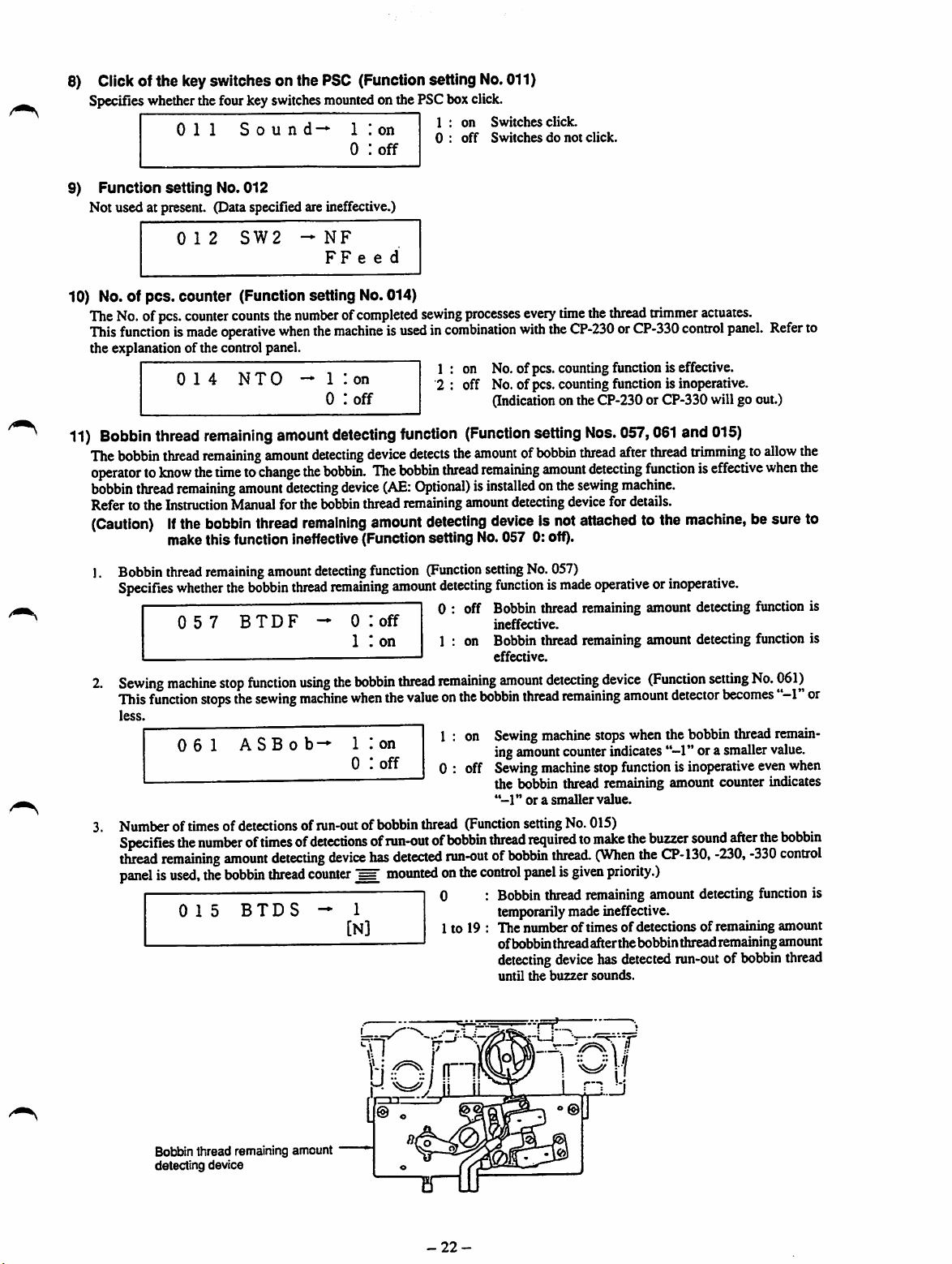
8) Click of the key switches on the PSC 22
9) Function setting No. 012 22
10) No.ofpcs. counter 22
11) Bobbinthreadremaining
OF
THE
CONTROL
of
the control panel 6
PSC
for
functions
BOX
amount
PANEL
detecting
function
12) Preventionof tangle-upthreadat the sewingstart 23
13) Intermediate reverse stitching function 24
14) Number of revolutions at low speed 25
15) Number of revolutions for threadtrimming 25
16) One-shotautomaticstitchingspeed 25
17) Adjustmentofpedal stroke 25
18) Compensation of the neutralpointof the pedal 27
19) Functionofauto-lifter 27
20) Selectionof the presser footliftingfunctionof the pedal(PFLtype) 28
21)
Compensation
22) EBT change-over speed 31
23) Effective diameterof motorpulley 32
24)
Presser
25)
Reverse
26) Needlebar
27) Reverse stitching (for start) function 32
foot
rotation
up/down
ofthe
lifting
timing
function
function
position
for
after
for
turning
thread
raising
retaining
ONthe
trimming
the
needle
function
solenoid
(for
after
thread
for
KFL
reverse
ofPFL
trimming
stitching
type)
28) Auto/manual change-overfunction for overlapping speed 33
29) Direction of rotation of the motor 33
30)
Accumulated
31)
E^PROM
reset
length
oftime
during
which
the
sewing
machineisenergized
32) Monitorof the state of inputsignal 33
33) Hysteresis of troubles 33
34) Communication facility 33
35) PSC box version management 33
(4) Examplesof applications
.'.
1
1
2
4
16
16
22
28
32
32
32
33
33
34
5. EXPLANATION OF ERRORS ANDCORRECTIVE
6. HOWTO CHANGE OVER THE SEWINGMACHINEFROMTHE STANDARD TYPE TO
THE
MACHINE
(1) Partsrequired for the modification 44
(2) How to assemble the parts 44
(3)
Adjusting
WITHANAUTO-UFTER
the
pressure
requiredtodepress
CONTROLLED
the
MEASURES
back
partofthe
BYTHE
pedal
PEDAL
(PFL
TYPE)
(4) Settingfor the functionsof thePSCbox 44
(5)
Automatic
compensation
ofthe
neutral
position
ofthe
pedal
sensor
38
44
44
45

7.
AUTOMATIC
(Only
forthe
8.
HOW
TO CHANGE THE
9. EXPLANATION OF FUSES 47
(1)
Replacing
10. CONNECTOR CONNECTION DIAGRAM 48
11. OPTIONAL CORDS 51
(1)
Junction
(2)
Junction
(3)
Junction
12. HOWTO REPLACETHE CIRCUrrBOARDS - 53
13.
CIRCUIT
14.
BLOCK
15.
BLOCK
16.
BLOCK
PRESSER
sewing
the
fuses
codeA
cordAasm.
cordAasm.
BOARD
MOUNTING
DIAGRAM
DIAGRAM
DIAGRAM
FOOT
machine
SIZE
asm.
for
forthe
for24
(Single
phase
(Single
phase
(3-phasc
LIFTING
equipped
OF MOTOR PULLEY 46
sewing
No.ofpcs.
FUNCTION
withtheAK
machine
counter
for
device)
standing
FROM
work
THE
NEUTRAL
POSITION
Vdc
DIAGRAM
100-120
200-240
200-240
VAC)
VAC)
VAC)
45
47
51
52
52
64
71
72
73

1.
GENERAL
(1)
Features
1) The max.sewing speed control variableresistoris mountedon thecontrolpanel, therebyfacilitating operation.
2) The liquidcrystaldisplaypanelisintroduced astheindicatorofthecontrolpanel. Asa result,numericalcharactersareshown
on the LCD panel in larger size, thereby allowing the operator to read them at a glance.
3) The foot pedal can be operated applyinga light pressure on it whendepressingthe front part or the back part. This helps
achieve easier operation.
4) Material edge sensor (ED), bobbin thread remaining amount detecting device (AH)and foot pedal for standing work are
optionally available.
5)
The
motor is no longer equipped with a mechanical brake.
6) Contactless pedal sensor is introduced, thereby eliminating a contact point.
7)
The
sewing machine controller quickly stops the sewing machine with its needle down.
-1
-

2.
CONFIGURATION
O Power switch
O Control panel
0 Synchronizer
O L-shaped thread stand
0 PSC box
0 Max.sewingspeedcontrolvariable
0 Motor
resistor
O Operationpedal
O
One-touch
(S)
Wiper
0 Standlevelingscrew or caster
typereversefeedswitch
^ Resistorpack(It is not
-2-
equipped
with
theJE type
machine.)

O Power switch
Powerswitch for the motor. PSC and control panel.
9 Control panel
Usedto specifythe automatic reversefeedstitchingfunction, pattemsewingfunction,etc.
® Synchronizer
Incorporatedinthe
sends an input signal to the main circuit board in the PSC box.
O
L-shaped
0 PSC box
thread
Comprisesacircuitrytocontrol
solenoid,
functions.
0
Max.
Allows
0 Motor
Operates
0
Operation
The
presserfootlifter(onlyforthe
0
One-touch
Manually
0
Wiper
Wipes
0
Stand
reverse
sewing
analog
the
pedal
front
and
operatedtomake
the
needle
leveling
Usedtoperform
0
Resistor
Automatically identifies thetypeof
pack
sewing
stand
feed
speed
control
adjustment
sewing
machineathigh
back
parts
type
reverse
thread
screworcaster
adjustmentsothat
(Itisnot
machine
solenoid,
variable
ofthe
of the
feed
switch
the
off
the
equipped
pulley,
the
sewing
etc.),apedal
resistor
maximum
speed,
foot
pedal
sewing
machine
sewing
machine
material
the
stand
with
theJEtype
machine
the
synchronizer
machine
sensortodetect
sewing
speed
medium
are
depressedtocontrol
equipped
perform
after
thread
rests
with
machine.)
head.
detects
and
motor,anoutput
pedal
without
speedorlow
with
AK-85).
reverse
trinuning
responding
securely
the
needle
circuitrytooperate
position,
changing
speed
feed
themotor
responding
the
sewing
stitching.
toa
leveledonthe
position
andapower
wiper
floortominimize
(upordown)
pulley.
toa
signal
speed
andtoactuate
signal
and
the
sewing
the
elements
(thread
circuitrytoactuate
output
from
the
the
output
from
the
PSC
vibration
during
the
PSC
thread
box.
speed,
then
trimming
respective
box.
trimmer,
operation.
-3-

3.
EXPLANATION
(1)
Control
(All
the
CP-30
CP-130
OF
THE
panelsofCP-30,
Indicationsonthe
CONTROL
-ISO, -230
control
PANEL
and
panel
-330
are
Illustrated in
•JUtCI
two
theirONstate
for
the
explanation's
sake.)
CP-230
v\
-i.-.—c
M
rs|g|
:N\j
\!8\}3\SS\SSU®
5|
i<®
SU®
•JUKI
(
nnnn
I
fnnnn
1
OUL'L'
I
1 f
uOOOJ(OOOOJ
nnnn^
CP-130
CP-330
UUKI
CP-330
3I/I/1-.
(\(\j
. , 1<® (s
|»01IS|uoi5Sj>{®
IjS
ran
r?fBIOOOoloO<»0
!^^^0OOu|Ot>uu
H
I
i
©
too
® (D ®
-4-
t
PPO
© o

No.
Power
o
0
e
o
0
0
0
0
0
0
0
0
0
0
0
0
0
0
0
0
0
0 No. of
Indicator
Max.
sewing
Reverse
Overlapped stitching pattern
Constant-dimension
Rectangular
Programmed
Programmed
Combinedstitching patternswitch •
Automatic
Asutomatic
Double
reverse
Double
reverse
Switches
Material
Cne-shot
Automatic
Thread trimming prohibition switch •
Bobbin thread counter •
Bobbin
counter
Bobbin thread amount setting switch •
pcs.
lamp
speed
control
stitching
for
edge
automatic
pattern
stitching
stitching
stitching
reverse
stitching
reverse
stitching
stitching
stitching
setting
the
sensor
stitching
thread
trimming switch • Whenthe
reset
counter•Counts
stitching
0 No.of pcs. counter reset switch •
No.of pcs. counter valuecorrection switch •
0
Step setting switch •
0
0
Numberof stitches/sensor change over switch •
0
Numberof stitches Inputswitch •
0
Teachingswitch •
Feedingdirection change-overswitch •
0
0
Stop-stateselectorswitch •
Presserfoot selectorswitch •
0
Used
0 Liftingtime setting switch •
Needleup/down compensating switch •
0
Re-sewing switch • If
0
programmedstitching pattem. this switchis used for re-starting stitchingafter
replacing
intenrupted.
Explanationofthe
(LED) • Lights up whenthepowerswitchis turnedON.
variable
selector
switch
selector
pattern
pattem
selector
pattem1switch
pattem2switch
(for
start)
(for
end)
(for
start)
sviritch • Usedfor
(for
end)
switch
numberofstitches
CN/CFF
switch•Rendered
switch
Comas
downthe
bobbin thread remainingamountdetectingdevice is installed
on
the
machine,
switch • Usedfor
the
initial
upthe
perfoims thread trimming.
numberoffinished
Used
Used
for
changing
Used
stitching
for
setting
the
Used
for
completion of operationsteps.
Used
Used
for
the
bobbin
thread
thebobbinfromthe
components
resistor
combined.
thread
pedal is held depressed.
numberofstitches
specifying
for
setting
runs
• Movethe variableresistor totheleft( ). and
themax. sewingspeed will belimited.
• Used to selecta reverse stitchingpattern.
switch •
selector
switch
Used
switch
switch
• Whenyoustartthe
sewing machine will run automatically untilthe material
edge is detected or the specified numterof stitches are
Used
retuming
over
specifying
Usedtoselectanoverlapped
switch
• Used to select a constant-dimension
sewing pattem.
• Usedto selecta rectanglestitchingpattem.
• Usedto specifytheprogrammedstitchingpattem1.
• Usedtospecifytheprogianuned
for
sewing
stitching
patterns
• Usedto turn ON/OFFthe
stitchingat the start of sewing.
• Usedto turn ON/OFFthe
stitching at the endofsewing.
turning
at the Stan of sewing.
• Usedfor
at the end of sewing.
• Usedforsettingthe
processes A through D.
effective
installedon the machine. Used for settingwhetheror not
the material edge sensor is used during sewing.
finished.
material
trinnming
for
prohibiting
amountofbobbin
the
counter
indicates
tlw
value.
for
setting
resetting
value
the
set
Used
for
Used
counter.
the
operation
Used
finishessewing whenthe specifiednumber of
stitches is reached or it finishes sewing when the
material edge sensoractuates.
for
inputting
putem.
Used
for
specifying
be
fed
either
the
stop-stateofthe
the
the
lengthoftinte
U»ed
when
stitching. 1 o
out
before
operation
ON/OFFthe
turning
ONA)FFthe
numberofstitches
whenthe
sewing
machine
edgeis
detected,
processevenwhen thefrontpartof thefoot
thread
trimmingatany
threadinsubtracting
the
numberoftimesofdetections.
shown
onthe
the
amountofIrobbtn
pieces
ofgannentseveiy
value
onthe
for
conecting
steps
the
numberofstitches
toa
nonnal
the
ofa
programmed
for
selecting
value
which
the
directioninwhich
directionorreverse
sewing
state
ofthe
presser
during
performing
the
needle
completionofthe
stepwherethe
stitching
stitching
0.0,
automatic
automatic
double
double
material
edgesensoris
withthis
the
machine
bobbin
thread.
time
No.ofpcs.
valueonthe
whether
foraprogrammed
has
been
machineatthe
foot.
which
the
up/down
operation
stitching
pattern.
pattem2.
0
and0with
reversefeed
reversefeed
reversestitching
reversestitching
tobesewnin
switch,
willstartthe
time.
method.
When
thread
counter
the
machine
counter
tozero
No.ofpcs.
sdtching
pattern.
the
sewing
machine
actually
sewn.
the
material
direction.
time
presser
footisraised.
compensating
steps
ofa
has
been
the
the
to
(0).
isto
of
CP-
30
o
o
j
j o
1
!
i
i
i
i
CP-
CP-
130
230
o 0 0
o
0
o o o
o c 0
o
o i
1 ^
! o
! o
c 0 o
c 0 o
o o
o o
o o o
0 o o
0 o o
0
o o
o
o
o o
o o
o o o
o
o 0
o 0
o
CP330
o
0
o
o
o
o
o
o
o
o
o
o
o
o
-5-

(2)
Explanationofthe
1)
Reverse
stitching
control
pattern
panel
(CP-130/-230/-330)
In the stitching mode, the machine performs reverse feed stitching at the start and
endofsewing.
The reverse feed stitching can be set to ON/OFF state. Furthermore, either single re
versestitchingordoublereversestitching (CP-230/-330)canbespecified. The number
of
reverse feed stitches and otherdata on the reverse stitching can be set by operating
the switches on the control panel.
A=B=C=D=0to19stitches
2) Overlapped stitching pattern (CP-130/-230/-330)
The machineperformsnormal feed stitching and reversefeedstitchingby theprede
termined number of times, performs straight line tacking, automatically performs
thread trimming and finishes the sewing.
The numberofstitches and the number of times by which the sewing is repeated can
bechangedby operatingtheswitcheson the controlpanel.
A=B=C=
D=0to9times
A=B=C=0to19stitches
D=0to9times
0to9
0 to 9
stitches
stitches
•
CP-230/-330
CP-130
c:p-130
CP-230
CP-330
3) Constant-dimension sewing pattern (CP-230)
Thefree
the number of stitches. When the specified number of stitches for process CD is
completed,
is specified, the
If theautomaticthreadtrimmingis not
cally
machine will run at low speed (perform compensating stitching).
If
pedal,
stitches.
Thenumber of stitchesandautomaticthread trimmingarespecifiedby operating the
switches on the control panel.
you
A=B=
stop.
return
the
stitching
the
sewing
Now,
the
machine
0 to 19
process
machine
ifyou
foot
pedal
will
stitches,
-6-
ina
reverse
machine
operate
automatically
willautomatically
the
One-touch
toits
neutral
continue
sewing
CD=0to
feed
stitching
stops
perform
speciHed,
type
position,
regardlessofthe
500
stitches
patternisused
(ifthe
automatic
threadtrimming).
the sewingmachine will automati
reverse
stitching
then
depress
specified
the
astheset
thread
switch,
front
number
value
trimming
the
sewing
partofthe
of
of
foot

4) Rectangular
5) Programmed stitching pattern (CP-330)
The
constant-dimension
the
numberofstitches
loweringofpresser
liftingofpresser
< How to set data on a program >
stitching
D
c c
D
pattern (CP-230)
A
A
N
B
sewing
(Max.
500),
foot
and
normal/reverse
footisspecified
The constant-dimension sewingprocess has four operationsteps. The machine auto
matically stops running upon completion of the sewing of the number of stitches
specifiedforeachstep ofoperation. If you operatethe One-touchtype reverse stitch
ingswitchafterthe sewing
(performscompensating stitching). For the last operation step, you can make the
sewingmachinecontinuesewing regardless of the specified number of stitches by
returningthe foot pedalto its neutral position then depressingthe from part of the
pedal. Note thatthe machinewill automaticallyperformthread trimmingif the auto
matic thread triimner is specified.
Thenumberofstitchesand
switches on the control panel.
process
canbeprogrammedasmanyas15
needle
up/down
feed
(for
KFLorPFL
A=B=
0 to 19
stop
mode,
stitching
type),
machine
automatic
stitches,
C=I>= 0 to 99
automatic
canbeseparately
the
time
during
hasstopped,themachinewillrun at low speed
threadtrimming arespecifiedby operatingthe
stitches
operation
thread
specified
which
0 O O
steps.
trimming,
for
the
presser
The
sewing
continuous
the
respective
footisraised
conditions
operation
steps,
operation
can
alsobespecified.
including
lifting/
steps.Ifthe
Example of a pattern
10
4lJl
20
Step 1
10
Steps
Datasettingstatefor step 1
/—
s 1
f
1
LU
Step
1
U
X
Step'
%
20
Steps
EQ>§
-'-(D
Nf
0 0
•JUKI
'v'n'I
kE|
•tc
cooa
uuuu
X
CP-330
-i-Hgte
I s
'-•!
s'U
__W
0 o
Data
programming
illustrated ontheleftas an
(Step 1)
1.
Press
grammedstitchingpattern 1.
2.
Programmed
number
3.
Confirm
of
stitches
4. Setthe
rectionchange-over switch
5. Setthe
Stop-stateselectorswitch
(Caution) Ifthe stop-state of the sewing machine is
6. Setthe
the upperpositionusingPresser foot selector switch 0 .
If
you
footis in the
using
Lifting
which
specified, it will be set to 60 sec.
k
Data
setting
procedureisdescribed
example.
Programmed
ofstitchesanddataon step 1are shownonthe LCD.
thatdataonstep1areshownontheLCD. Thensetthenumber
to20usingNumberofstitchesinput
feeding
stop-state
automatic
dure is not allowed to go forward to the next
position
wanttospecify
the
presser
stitching
stitching
direction
ofthe
sewing
pattern
thread
ofthe
presser
the
highest
positionin particular, setit to adesiredvalue
time
setting
footis in the
range:
0.10
¥
0
panem1switch
1 is
specified
to the
normal
0.
machine
0.
trimming
foot
when
lengthoftime
switch
@ . Ifthe
highest
sec.to99.95
below
direction
tothe
^ ,
the
during
position
sec.
sewing
GD
9»
while
taking
O to select pro
andthe
predetermined
switch
O .
using
Feeding
needle-down
data
setting
machine
which
the
length
oftime
isnotparticularly
thepattern
stop
using
set
to the
proce
step.
stops
presser
during
di
to
^
-7-

(Step 2)
7. Make the LCD indicate step 2 by pressing
of Step settingswitch 0 once.
/•
s
1 n
1 u
L
EQ>s
1
3^
8. Set the number of stitches to 10 using
stitches input switch 0 .
9. As in the data setting procedure for step 1, set the
feeding direction to the normal direction, the stop-state
to the needle-down stop state and the presser foot
position to the upper position.
the+switch
Number
of
Step
steps
m
©
1
1
a
BQ>«
-•-iD
(Step 3)
10. MaketheLCDindicatestep 3 bypressing the+switch
of Step setting switch 0 once.
11
Set the numberofstitches to 20 using
stitches
input
switch
O.
12
As in the data settingprocedure for step 1 and step 2,
set
tb.
feedingdirection to the normal direction, the
stop-statetotheneedle-down stopstateandthepresser
foot position to the upper position.
Number
of
2
¥
o o
/•—
s 1
:>
j
LU
5)
O O
(Step 4)
13. Makethe LCDindicatestep4bypressingthe+switch
of
Step
settmg
switch0once.
Set the number of stitches to 10 using Number of
w
I n
I u
-l-§|kE3
-L|Xi
14.
stitches
Setthe
15.
Feeding
Set the
16
maticthread
input
switch
feeding
direction
stop-state
trimming
O.
direction
tothe
normal
change-over
of the
usingStop-state selectorswitch
switch
sewing
machineto the auto
direction using
0 .
17.
Set the
position
machine
selectorswitch o
Specify
Step
4
©
18.
stitching
0 0
1
r*-
{M'
Dataonanother
sewing
process
^
canbeprogrammed,
taking
the
aforementioned
-8-
stitching
setting procedure.
19. Furthermore,itispossibletospecifythedoublereverse
stitching
start)switch 0 andDoublereversestitching(forend)
switch
(Caution) Ifyou operate the One-touch type reverse
procedure,
of the
presser
stops
totheupper
the
reverse
(for
start)
(forend)
feature
0.
stitchingsvi/itchatthe completionofevery
operation step, the sewing machine will
run at low
stitching).
switch0.This
using
for
position
stitching
switch0and
Double
speed
(perform
programmed
footwhenthe
usingPresserfoot
feature
using
Automatic
completes
reverse
stitching
compensating
stitching
sewing
Reverse
reverse
thedata
pattern
(for
2.

< Teaching
Lithe
been actually sewn.
mode
teaching
>
mode,itispossibletosetthe
g)#
/
1
s
EQ>e
< One-shotautomatic stitching>
The
one-shot
automaticstitchingfunction can be
numberofstitches
(g(g)(i)
1
1
--ill
separately
ina
programmed
setby steps.
stitching patterntothenumberof stitchesthathas
1. In a programmed stitching pattern, press Teaching
switch O to
2.
The
indication
cator changes
machine has entered
3. Depress the front part of the pedal to make the sew
ing machine perform sewing until the last stitch of
the current operation step is reached.
(Caution)
4. Return the foot pedal to its neutral position to make
the sewing machine stop running. Now, the number
of
stitches
trol panel.
5. Proceed to the subsequent step using Step setting
switch O or make the sewing machine perform
thread trimming. This completes the input of the
number of stitches for operation step 1.
specify
shownonthe
to"—T."
the
The
numberofstitches
when
the
sewing
operated
stitching
which
or
switch.
has
been
the
teaching
This shows that the sewing
teaching
using
mode.
numberofstitches
r
mode.
will
notbeinput
machineismanually
the
Compensating
sewnisshownonthe
indi
con
<
/—
j
L-,
< Continuousstitching mode >
In
this
mode,
itis
possibletomake
-|->S
-'4fl
In the programmed stitching pattern process, press
One-shot automatic stitching switch O to specify
the one-shot automatic stitching function.
is shown on the control panel, which shows the
one-shot automatic stitching function has been speci
S
@1
r
1
LU
EQ>g
J.fTl
fied.
In the step where the one-shot automatic stitching
function has been specified, the sewing machine will
automatically continue sewing, once the sewing ma
chinestarts running,until theend ofthe stepis reached.
©
the
sewing
machine
0^^
execute
the
subsequent
step
after
the
completionofthe
In the programmed stitching pattern process, press
Stop-stateselectorswitch
stitching mode.
Aslong as the continuousstitching mode is specified,
you can make the sewing machine execute the subse
quent step after the completionof the current step by
depressing the front part ofthe foot pedal.
Oto
current
step.
specifythecontinuous
<To
operate
the
control
panelincombination
•
When
the
control
panelisusedincombination
predetermined
•
Carefully
numberofstitches
read
the
Instruction
butbyan
Manual
for
with
input
the
the
with
signal
material
material
the
material
ofthe
edge
-9-
edge
material
sensor
sensor
edge
before
>
sensor,
edge
using
the
sensor.
the
sewing
material
process
edge
canbecompleted
sensor.
notbythe

6) Combined stitching pattern
Reverse
^
canbesewn
stitching
pattern,
with
overlapped
combinedasdesired.
stitching
(As
pattern,
programmed
manyaseight
stitching
different
pattern^and
patterns
programmed
canbecombined.)
stitching
panem
Programmed pattern indication
Selected
•JUKI
Combined-stitching
indicator (flashes on and
Executed pattem indication
pattem
Indicationof the programmed pattem
thatisbeing
and
off)
•JUKI
pattern indicator (fights up)
CP-330
ofO
Step
execute
CP-330
No
(flashes
on
Programming
Press
the
mode
for the combined stitching
[Indications shown on the LCD panel go out excluding
a partofthem (only the step No. indication and the
selected
Now, press the keys corresponding to the pattems to
becombinedinthe order of sewing. (Every timeapattem
is
selected,
located on
to the selected
the step No. increasesas
If
you want to execute the same pattem twice continu
ously, press the pattem switch twice.
2
Execution
a. Upoii completion of the programming procedure, press
mode
(^)
key
twicetoselect
pattem
indication stays ON.)]
the
the
sideofthe
pattem
mode
pattern
pattem,
lights up
1,2,3
the
programming
pattem
indicator
which corresponds
and,
at the same time,
and so on.)
program.
" "
the key again, and the machine will enter the
combined program executing mode.
b. Every time the thread trimmer actuates, the machine
proceeds to the subsequent pattem which has been se
lected. (The selected pattem indicator " " flashes
on and
off
to indicate the pattern that is being execut
ed.)
c. To Hnish the combined pattem stitching program, press
anotherpattem selectingkey after thread trimming.
(Caution) If
the
thread
trimmer
completion of a pattern,
proceedtothe
subsequent
actuates
the
machine will
program.
before
Combined stitching
Indicator (lights up)
pattem
Program No.that is
being executed
-10-

7)
Howtouse
the
bobbin
thread
counter
(CP-130A230/-330)
The machine detects the number of stitchesfinished. The preset value on the bobbinthread counter is subtracted in accord
ance with the number of stitches finished (Every time the detectordetects that the sewingmachine has finished 10 stitches,
1 is subtracted from the preset value on the bobbin thread counter.) When the value on the counter becomes a minus value as
" 1 0
-1,"
the buzzer peeps three times to wam the operator that the time to change the bobbin thread has come.
1. Pressbobbin thread counter reset switch O to return
Preset
key
n
u
thevalue indicatedon bobbin thread counter 0 to the
initialvalue (it has beenfactoiy-set to
delivery).
(Caution)
The
bobbin
during
thread
thread
sewing.
trimmer
actuate
In
counter
this
"0"
case,
once.
at the
cannot
make
K
2. Specify an initial value desired using bobbin thread
amountsettingswitch 0 .
(The initial value can be set to 9999 at the maximum.)
<Initial
Preset key
CP-130,
valueonthe
o
-230
bobbin
thread
counter
CP-330
for
reference>
3. Once the initial value is specified properly, start the
sewing machine.
4.
Whenaminus
buzzer peeps three times, replace the bobbin
valueisshownonthe
counter
5. After the bobbin thread has been properly replaced,
press bobbinthreadcounter reset switch O to return
the
valueonthe
value. Now, re-start the sewing machine.
6. If the
remaining
or
the
bobbin
counter indicates a minus value, adjust the initial value
appropriately using the
thread
amount
bobbin
thread
countertothe
amountof bobbinthreadisexcessive
thread
runs
out
before
the
bobbin
"+"
or switchofbobbin
adjusting switch 0 .
time
l>e
and
thread
initial
thread
of
rest
the
the
Thetablebelowgivestheinitialsetting
bobbiniswound
outsideofthe
Thread
Spun Uiread#50
Conon
thread
♦
Actually,
thickness
the
bobbin
ditions.
(Caution)Ifthe
with
thread
bobbin
caseisreached
Lengthofthread
wound
round
#50
the
bobbin
thread
and the sewing
thread
counterinaccordance
bobbin
device,
the
bobbin
tothe
the
bobbin
36
m
31
in
counterisaffected
speed.
thread
counterisusedincombination
thread
amount detecting device. So,be sure to use thedeviceafter
values
forreference
extent
thatthe
Valueonbobbin
counter
1200(stitch length: 3 mm)
10(X)
(stitch length: 3 mm)
Thread
So,
adjust
the initial
with
the
counter
when
pinholeinthe
thread
tension
rate
by the
material
value
operating
indicates
the
100%
of
con
the
If the remaining amount of bobbin thread is excessive
.... Increase the initial value using the'Vswitch.
Iftheremainingamountofbobbin threadis insufHcient
....Decreasetheinitialvalue usingthe switch.
with
the
bobbin
numberofdetections
carefully
thread
remaining
ofthe
bobbin
readingthe Instruction
the bobbin thread remaining amount detecting device.
-11
-
amount
thread
detecting
remaining
Manual
for

8) No.
off
pcs.
Reset
counter
key
(CP-230/-330)
Reset
key
It
u
No/
(+.-)key
The No. of pcs. counter counts up the number of finished
productseverytimethemachineperformsthread trimming.
(0-»l-»2
R
Thevalueon theNo.ofpcs.countercan be modifiedusing
No.ofpcs.
thecontrolpanel. The valueon the No. of pcs. counteris
reset
to"0"by
counter
pressing
-»9999)
value
No.ofpcs.
correction
switchOmounted
counter
reset
switchO'
on
9) Re-sewIng
The
re-sewing
Slept
CP-230
switch
switchisused
(p
gi;
W
V
(CP-330)
when
(g>(^
.a
£
n
n
u
u
Vw/
W
D
Step
Step
2
CP-330
the
bobbin
thread
runs
out
during
the
programmed
The bobbin threadrunsout during the operationsteps
forsewing. 0
Bringthefoot
sewing
foot
pedaltomake
TurnON
A
j
Replace
headand
reverse direction to return the material to the position
where
machine
Depress
5.
position
6.
TurnONre-sewing
Then,
The
sewing
grammed stitching pattern.
» Ifthe needle thread breakswhile the sewing machine is
runninginthe
4
steps
pressing
its
neutral
foot
pedaltoactuate
machineheadandslightly feed the materialin there
verse
enables
thefree
as described in the aforementioned steps 5) and 6).
(Caution)
stitch
pattern
sewing
steps.
pedal
toits
neutral
position to
machine
the
the
direction,
stop.
Now,
depress
the
the
thread
trimmer
re-sewing
the
slightly
sewing
tosewoverthefinished seam. 0
the
O of
next
re-sewing
position.
the
sewing
switch
bobbin
withanew
feedthe
was
interrupted
front
part of the foot
step
2is
switch
stepisindicated
machine
sewing
free
switch
and
machine
mode.
continues
sewing
Then,
the
press
O • O
material
reached.
O at
mode
0 ,
depress
thread
re-sewing
tocontinue
Then,
one,
thread
onthe
toallowthe
pedal
stop
on the
the
sewing
( ®
bring
the
thebackpartofthe
trimmer.
switch0.This
operate
the
back
actuate.
machine
position
control
Toreturntothefirstoperation step
make
partofthe
O
the
machine
inthe
sewing
until
panel.
ofthepro
O)
foot
pedal
Re-thread
sewing
under
control
panel
off
the
stop
O •
after
to
the
the
programmed stitching pattern without
using
re-sewing
switchO,depress the
back part ofthe foot pedal to actuate the
thread
o
oo
trimmer.
panel give the step indication 1.
youcanstart
the
programmed stitching pattern.
This
makes
sewing
fromthefirststep of
the
control
Now,
-12-

10) Needle up/down
83^
compensation
T:
n
n
u
u
'+
switch (CP-130/-230/-33G)
GD
Eveiy
time
needle
up/down
pressed, the needle goes up when it is in its lowest position
or comes down when it is in its highest position. This
compensates the stitch by a
stitch length. However,
run continuously at
held pressed.
Also, note that the needle up/down compensation switch is
rendered ineffective after you have turn the handwheel by
hand.
The thread trimmer is operative only in the case of needle
up/down compensation after the front part of the foot
pedal has been once depressed.
low
compensation
halfofthe
note
that the
speed
evenifyou
switch
predetermined
machine
keep
the switch
O is
does not
11) Key
lock
function (CP-130/-230/-33D)
In
ordertoprevent
by
mistake,
thevalueon thebobbinthreadcountercanbechanged.)
*1'". (]
TTT1
Atcic
the
\
L Vj
the
setting
m
specified
switch
\A
dataonthe
canbe
•JUKI
numberofstitchesorthe
locked.
(Even
CP-330
'I
m
1/1
withthe
setting
stitching
switches
processes
areinthe
After the completionofthe setting of data on the
number of stitches, etc., turn OFF the power to the
machine
Turn ON the powerto the machinewhile simultaneous
lypressing automatic reverse stitching (for end) switch
O and the switchof
switch
O forprocessA with
Key
mark
completes the key-locking of the switches.
(Ifthekeymarkisnotshownonthecontrolpanel,carry
outtheaforementionedsteps 1 through 3 again.)
To release the switches from the key-locked state,
performthe aforementioned steps 1 and 2 .
(The key mark will go out and the switches will be
released h-omthe key-locked state.)
once.
® is
(A,
key-lock
shown
B,C
andD)from
state,the
onthe
pattern
number
fingers.
of stitches
control
being
tobe
panel.
changed
sewn
setting
This
and
:
l\l
+
-13-

12)
^ •
(Caution)Ifthe
ON/OFF
When
material edge sensor becomes effective.
• If
when
the
the
material
the
Manual for
switch
material
sensor
@ofthe
edge
sensor,
edge
sensorisspecified,
detects the material edge.
material
edgesensor is usedin
the
material
material
whichisoptionally
edge
edge
the
sensor
sensor
available,isconnectedtothe
sewing
machine
combination
beforehand.
will
with
automatically
the
control
4
control
panel,
stop
runningorperform
panel,
carefully
/—
<
s
f
in
1
lU
W
the
ON/OFF
read
h
&
switchofthe
thread
trimming
the
Instruction
13)
Automatic
thread
CP-130,
trimming
-230
switch
14) Threadtrimmingprohibition switch
4
@
CP-330
• This switch is used to automaticallyactuate the thread
trimmer
matically
(Ifthe
the thread trimmer will actuate after the sewing machine
completes
• This
• If
in a
process
stopsorwhen
automatic
the
switch
isusedtotemporarily makethe
ming function inoperative.
The
other
performance
affected by this switch.
the
automatic
thread
trimming
specified,
but stop with its needle up.
the
wherethe
the
reverse
automatic
thread
prohibition switch are both
machine
will
sewing
material
stitching
reverse
stitching
of the
sewing
trimming
not
perform
machine
edge
sensorisused.
(forend)is
specified,
(for
end).)
thread
machine
switch^and
thread
trimming
auto
trim
is not
the

15)
One-shot
•
This
make
driving the sewing machine once.
autonnatic stitching switch
switchisused,
the
sewing
machine
inthe
constant-dimension
automatically
stitching
perform
sewing
mode
atthe
orinthe
specified
process
speed
where
until
theendofthe
m
the
material
edge
sensorisspeciHed,
processisreached
only
to
by
CP-130,-230
CP-330
-15-

4.
EXPLANATION
(1) Howtoset
Various
faceofthe
functions
PSC
qDDDCSD
OF
for
functions
canbeselected
box.
<^l
THE
PSC
and
BOX
specified
using
J
the
four
setting
switches
DDL-5550
*
After
the powerto the sewingmachineis turnedON,the model
ofsewing machine used is shown on the
and
liquid
crystal
c ••••
display
12
LCD.
mounted
3 4
onthe
front
(Caution)
1)
Setting
Functions
that
canbespecifiedislarger
User
Service
1. TurnOFF the power to the machine once.
2. Call the user level or service level for the setting of
functions.
<
Howtocall
Pressing the 2 [•]
chine.
<
Howtocall
Pressing
chine.
Then,press the 3 [ITEM]switch.
Never
for
functions
canbesetin
level
level
the
the
the 1 [•)
operate
two
(ITEM
(ITEM
103,105
user
switch,
service
switch,
the
switchesInany
different
No.
No.
and
level
levels,
than
thatinthe
001to006,008to010,012,018to020,030to
007,011,013to015,035,036,039to049,051to054,058,060,062,064to066,075,100
107inaddition
>
turnON thepowerto the ma
level
>
turnONthe
power
i.e.,
user
way
user
level
level.
tothe
items
tothe ma
other
thanthe
and
service
Set
for
functionsineither
accepted
procedure
level.
Inthe
descril>ed
service
level,
level
accordingtosewing
033,037,038,050,055to057,
under
theuser
Switchoperation
Callingthe user level
Callingthe servicelevel
level)
below.
the
numberoffunction
conditions.
059,061
Indicationonthe
ITEM
NO.
001
and
LCD
N-SOFT
items
108)
to
.
•DP
3. Indication shown in the illustration on the right will be
given
onthe
LCD.
(If
the
indication
LCD,re-perform theprocedure fromstep 1 .)
does
not
appear
onthe
DDL-5550
••QD
-16-
ITEM
NO.
001
N-SOFT
,

Then, select the item No. corresponding to the function
you want to specify by pressing the 1 [•] switch or 2
[A]
switch.
(Refer to the function setting table for the description of
items.)
5. Once the item No. corresponding to the function desired
has been selected, press the 4 [SET] switch.
Example)
Function for changing the number of stitches for the
soft-start function (0 to 5)
* For example, the numberofstitches for the soft-start
function is changed to five.
6. The indication shown on the LCD will
change
as illus
trated in the figure on the right. Now, the set value can
be changed.
7.
Press
the2 [•] switchfivetimesto
stitches
for
the
starttoto
five.
change
the
number
(To decrease the number of stitches, press the 1 [•]
switch.)
of
Switch operation
1 2
D
or
Example)
Changingthe numberof
stitches
for
function
the
12
3 4
Cflop:
1 2 3 4
(••••
D
soft-start
Indicationonthe
Selected
item
indicated.
ITEM
001
001
N-SOFT
001
N-SOFT
NO.
No.
is
-»
N-SOFT
LCD
- 0
(N)
- 5
(N)
8. After the completion of data
the
4 [SET] switch to enter
changing
the
modifiedvalue.
procedure,
(Caution) If you omit this procedure, the modified
value
wiil
notbeentered.
9. The
10.
11.
indication
givenontheLCDwill
change
toshowthat
data onthe subsequent functionitem No.can be modified.
Toput
forward
[ITEM] switch to return the indication on the
function
the 1
[T]
After
the
orput backtheitem
setting,
andcalltheitem
switch or 2
[A]
switch.
completionofoperation
No.,
press
LCD
No.
desiredbypressing
described
instep 8 ,
turn OFF the power to the machine, then turn it ON. This
will
return
the
machine
tothe
normal
operation
press
firstthe3
to the
mode.
cnnoQ;,
10
CQDQQ
II
12
3 4
T A
"I"
12
1 2
[©a
•O-
3 4
001
002
ITEM
Selected
indicated.
DDL-SS50
N-SOFT-5
•0
ED
NO.
-
item
No.
(N)
—0:off
Iron
002
ED
is
T7

(2)
•-*shows
PSC
function
the
setting
set
value.
table
(Refertothepagesforrefereitce for details.)
Numberofstitchesforthesoft-staitfunction (See 1)onpage20.)
A
001
Mateiial
edgesensor
N-SOFT
function
— 0
(See2)onpage20.)
002 ED — 0 :
inaierial
edge
1 I
sensor
A
Thieid
tiiimninit
functioninaceonJance
wiA
the
003 EDTRM — 0 : off
A
Numberof
stitches
forthematerialedgesensor(See2)onpage20.)
1 ;
004 ED (N) ^ 5
A
Flickerleducine function (See 3) on page 21.)
005 T-Acc ^ 0
A
Bobbin thread countingfimctitm (See4) on page 21.)
006
A
Unitusedfor
007 Ratio —
Numberofrevolutions
008
A
Thread
trimming
009
A
Stxci&aticoofthe
010
A
CUick
(See 8) on page 22.)
Oil
SW2on the simpliftedpanel (See9) on page 22.)
012
A
Sewing
machine
013 AsCnt — 0 :
No.ofDCS.
counter
014 NTO — 1 : on
Numberoftimesofdetectionsofrun-out
015
SCBob
count-down
ofthe
for
iBveisestitdiing
S-BT
prohibiting
TRMINH
needle
bar
position
NFS
Sound
SW2
stopinaocoidance
(See
10)onpage
BIDS
— 1 : on
bobbin
thread(See4) onpage21.)
—
function
(See
— 0 :
when
the
sewing
—
^
with
the
bobl^
22.)
ofbobim
— 1
0 :
1/10
1/
(SeeS)on
1900
6)on
page
machine
Down
Up
NF
FFeed
thread
counter
thread
1 I
stops
1 I on
0 :
1 I
0
(See
[N]
off
on
(See2)on
on
[N]
1
off
15
page
[spm]
21.)
off
on
(See
off
(See4)on
off
on
:off
11)onpage
[N]
21.)
7)n
page
page
page
20.)
21.)
21.)
22)
Preventionof tangle-upthreadat the sewingstart (See 12)onpage 23.)
018
A
Needlethread releasing(for start) function (See 12)on page 23.)
019
A 1 :
Numberof condensation stitches (See 12) on page 23.)
020
A
Numberof intennediate reverse feed
030
A
Number of inrennediate reverse feed stitches (See 13) on page 24.)
031
A
Conditions
required(omake
the
sewing
machine
032 OBTS ^ 0 :
A
Thread
trimming
13)on page 24.)
BNC
THold
N-CS
OBT
N-OBT
the
intentieditie
isinthesiopstate (See13)on
functioninaecordanoe
with
— 1
0 :
— 0 :
- 1
function
(See 13)on page 24.)
— 0 :
1 I
^ 4
revtne
tUKhing
page
24.)
1 I
die
intenxdiate
:on
off
off
on
[N]
off
on
[N]
function
off
on
tevene
033 OBTT - 0 : off
1 !
A
Ntunberxf
035
revolutions
atlowspeed (See14)onpage25.)
S-Pos
-•
Numberof
036
revolutions
forthread
S-TRM
trimming
—
Numberof revolutionsfor soft start function (See1) on page20.)
A
A
037
One-shot
038
Ftedal
stndtefor
039
automatic
stitching
starting
S-SOFT
speed
S-ASS
the
machine
P-SSP
(See
(See
—
16)on
—
17)on
on
200
[spm]
(SeeIS)onpage25.)
210
[spm]
800
[spm]
page
25.)
2500
[spm]
page
25.)
— 3.0 [mm]
Low-speed
040
opeiaiion
sectionofthe
P-LSA
pedal
(See
17)onpage
— 6.0 [mm]
Presser
foot
lift
staiting
041
Presser
042
foot
descending
positionofthe
P-FLW
starting
P-FLD
pedal
—
positionofthe
(See
—2.1
pedal
17)
page
[mm]
(See
17)onpage
— 1.0 [mm]
effective
stitching
25.)
25.)
wliil
(See
le
5.)
2
-18-

Pedalstroke 2 for making the thread trimmerstart (See 17) onpage25.)
Pedal
043
sMke
044
for
maldng
the
machine
P.TRM2
tcKh
P-MAX
die
largest
—
—5.1
nnmhcrofrevobdioos
[mm]
(See]7)onpige25.)
— 15.0 [mm]
Compensation
Selecticm
Lengthoftinte
ofthe
neutral
pointofthe
045
of auto-lifter (See19)onpage27.)
046
during
047
which
P-ANP
FLScl
the
T-FL
presser
pedal
- 0
— 0 :
footisheld
(See18)onpage27.)
sol
1 I
air
raised
(See
19)onpage
— 60 [sec]
Pedal
stroke
1for
making
the
thread
trimmer
start
(See
17)on
^gth
footis
048
ofdme
desceadittg
049
dufing
P-TRMl
which
thenatton ofthe
(See19)onpage27.)
T-FLWT
—
—3.5
inacfaineispmiiibtted
[mm]
while
-* 140 [msec]
Presser
footlifting
050
A
Compensasioa
(forstin) (See 21) oo page 28.)
051
Compensation
(liorsiart)(Sce21)onpage28.)
052
Condensation
(forend)(See21) on page28.)
053
function
ofthepedal (See20)onpage28.)
PFL
of dielinuogfortuningONthe
T-SON
ofthe
timing
for
turning
OFFthe
T-SOFF
ofthe
liming
for
turning
OFFthe
T-EOFF
— 0 :
1 .'
salenoid
lorrevtne stitdiiiii
^ 3
tidcaotd
(or
vcvenc
—
12
solenoid
forlevene
—
18
off
on
stitching
sdrehing
page
the
27.)
25.)
ptesser
Auto/nanuj]
Sewing
Scwutg
device (See 11)00 page 21) *
Auto/tnanual
EBT
Condensation
is set to 1 (See12)on page23.)
Condensation
isseito2
Directionofrotation
Aocnnndatedlengihoflinie
E2PR0M
Monitor
change-over
059
nBdrineaop
060
inichinc
stop
061
change-over
062
change-over
064
stitching
065
stitching
(See12)on page23.)
066
075
100
reset
ITEM
ofthe
stateofinput
fPO*]
funaioo
for
reverse
aiuhing
SBTO
function
iaane<fitielyaftgtevtrietgtching(fg
-
SBTQ —
fuocooo
usingthe
bobbin
thmd ittBtininc
ASBob
function
for
overlapped
—»
stttching
BTOp -
speed
(See22)onpage31.)
S-Wait
-•
solenoidONdming
T-CSl
solenoidONliitiing
T-CS2
ofthemotor (See29)on page33.)
DM
doing
STO
(See31)onpage33.)
NO. — •
-
when
the
—
when
the
—
—
whicb
(be
sewing
midiinebaxrgiaed
—
101
signal
for
ITEM
7 0
11111111
(for
slot)
(See
27)onpage
Auto
Manu
Stan)
(S«27)ooptef7?)
0 :
off
1 I
on
1 I
on
0 :
off
speed
(See
28)onpage
Auto
Manu
180
[spm]
numberofcondensation
-15
numberofooodensadon
-15
ccw
cw
(See
30)onpage
0 [min]
ResEEP
No.
102
(See
32)on
deteccinc
satcfaes
$titd«s
page
31)
33.)
33.)
33.)
Effective
diameterofmotor
054
Prcsscr
foot
lifting
055
A
Reveiserocationluncticnroriitsing
056
A
BoNnn
thread
remaining
057
A
Predetermined
upper/lower
058
PCDMP
fimction
FLAT
RATRM
amount
BTDF
HPos
pulley
after
the
needle
position
thread
detecting
(See23)on
page
trimming
(See
— 0 :
aiierthiudtiiiiiTiing
— 0 I
funaion
— 0 :
ofthe
needle
bar
— 0 :
32.)
105.0 [mm]
24)onpage
off
1 I
on
(See
25)on
off
1 I
on
(See
11)on
off
1 I
on
(See
26)on
off
1 I
on
page
page
page
31)
31)
21)
32.)
Registered
—
Receiving
ITEM
troublesofITEM
modeof
No.103 (See33)onpage33.)
EG
EXIT
E2PR0M
(Sec34)onpage33.)
NO. — •
105 RxCopy
Transmission
Version
A)
User
*) Thefunctionis renderedeffectivewhentheSC-2 istisedin combination
the sewingmachinewhichisequippedwitha bird's nestpreventiondevice.
(Caution) The function
-
19-
modeofE2PR0M (See34)cnpage 33.)
ITEM
management
Version
level
modelofsewing
NO.
No.of ITEMNo. IPS (See 35)on page33.)
setting
tableisprepared
machine.
107
TxData
for
0
the
with*
DDL-5550

(3)
Explanationofthe
1)
Specifying
1.
Numberofstitches for the soft-start function (Function setting No. 001)
The needlethread mayfailto interlacewiththebobbinthreadatthestartof sewingwhenasmallerstitchlengthor athicker
needleis used. To solvesuchproblem, this
successful formaiion of the starting stitches.
2.
The
Thelimitof
2)
Material
This
functionisrendered
for the material edge sensor for details.
(Caution)
I.
ON/OFF
Selects
the
the
numberofrevolutions for
edge sensor
The
sensorand whenthe
ofthe
either
material
functions
soft-start
sewing
speed
effective
specified
material
the
material
edge
sensor
function (Function
N-SOFT-
the
soft-start (Function setting No. 037)
whilethe
S-SOFT
(ED:
Optional)
data
edge
edge
ON/OFF
soft-start
when
the
willbeineffective
sewing
sensor
(Function
sensorismade
switch
setting
function
function
material
isusedto limitthesewingspeedat thesewingstart,therebyensuring
function
works
(Function
edge
sensor
when
machine
isequipped
setting
operativeorinoperative.
(J)
mountedonthe
No. 001,037)
The soft-start function is not speciHed.
The
numberofstitchestowhich
isalso
changed.
Datasetting range
130 to 2000 [spm] <10/s.p.m.>
setting
(ED)isattached
the
sewing
No.002)
off:
Material edgesensoris
ineffective.)
on : Materialedge sensor is effective.
No.
002to
tothe
machine
with
control
isnot
the controlpanelof
(When
the
panelisgiven
004)
machine.
Refer
equipped
CP-130/-230/-330
priority.)
inoperative.
the
soft-function
tothe
Instruction
with
the
CP-130
or higher class.
control
(Nos.003 and 004 are
works.
Manual
material
edge
panelisused,
Thread
trimming
Selects
either
CP-130/-230/-330
priority.)
Numberofstitches
Specifies
material.
(Caution)Ifthe
functioninaccordance
the
thread
control
forthe
the
numberofstitchestobe
sewing
sewing
s.p.m.,atleast
thatthe
setto1or2.Inthiscase,
without fail in consideration of the sewing speed or lowerthe sewing speed.
trimming
panelisused,
EDTRM^O
material
N]
speedishigh,
machine
stops.
five
sewing
machine
function
the
edge
sewn
-5
For
stitches
with
the
using
automatic
sensor
(Function
until
the
there
example,
are
required
will
not
specify
Afterthe
sewing
004)and
willautomatically performthread
material
the
material
thread
machine
0 to 19
isa
minimum
when
stop
according
the
numberofstitches
material
machine
stop.
edge
sensor
edge
trimming
Automatic
has
been
The
004)thenautomatically
material edge has been detected.
setting
stops
stitches
edge sensor
willsewa
If"1:on"is
(Function
sensor
switch@mountedonthe
thread
detectedisineffective.
machine
sewsapredetermined
No.
004)
after
the
<l/stitch>
numberofstitches
the
tobe
sewing
sewn
machine
until
tothe
numberofstitches
thatis
detects
predetermined
selected
forNo.003,the
trirruning.
setting
made
trimming
material
No.
effectiveorineffective.
function
performs
edge
sensor
required
perform
the
sewing
machine
sufficienttomake
the edge of material, the
numberofstitches
sewing
machine
003)
(When
control
panelisgiven
afterthe materialedge
numberofstitches
threadtrimmingafter the
has
tobe
sewing
specified
detected
ata
stops.
the
sewn
until
speedof4,000
This
ifithas
the
machine
(No.
the
(No.
edge
of
the
means
been
stop
ED
sensor
(Material
edge
sensor)
-20-

3) Flicker reducing function (Function
This
functionisusedtoprevent
the
more
effective
(Caution)
4)
Bobbin
1- This function is used, when the control panel (CP-130 or higher class) is used with the machine, to indicate the remaining
2.
thread
amount of the bobbin thread while subtracting one from a predetermined set value every time the sewing machine finishes a
predeterminednumber of stitches. Referto the explanationof the controlpanel (on page II).
Unit used for count-downofthe bobbin thread (Function setting No. 007)
The imit used for the count-down (subtraction)ofthe bobbin thread counter can be changed.
the
function
0 0 5
The
more
speedofthe
counting
0 0 6 S C B o
the
will
work.
T-Acc-*
the
flicker reducing function works (the larger
sewing
function
hand
lamp
machine
(Function
b—1
setting
from
will t>ecome).
on
0
off
No. 005)
flickering
setting
atthe
stait-up
Data sening range
Oto
8
0 : Flicker reducing function does not work.
8 : Flicker reducing function works most effectively.
Nos.
006,007,013)
(Caution) If
ofthe
the
set
the
bobbin
the
OFF
control
counting
sewing
value
state,
panel
function
machine.
becomes),
thread
the
indicationonthe
willgoout
is inoperative.
The
the
counting
and
larger
the
lower
function is
the
bobbin
value
the
LCDofthe
isset.
start-up
set
to
thread
007
Ratio—
1/10
1/15
1/10 : 1count-down for every 10 stitches
1/15 : 1 count-down for every IS stitches
1/20 : 1 count-down for every 20 stitches
3. Sewingmachine stop functionin accordancewith the bobbinthread counter (Function setting No. 013)
This function is used to stop the sewingmachine when the value shown on the bobbin thread counter becomes "-1" or less.
0 : off Sewing machine stop function is inoperative even when
0
13
A s c
t-
0
off
1
on
1 : on Sewing machine stops when the bobbin thread counter
the
bobbin
value.
indicates
thread
"-1"ora
counter
smaller
indicates
value.
(Caution) Ifthe bobbinthread counter indicate "~1" or a smallervalue during a sewing process, the sewing
machinewill
stop
after
the
completion of the
process
(after
thread
trimming).
5) Number of revolutions for reverse stitching (Function setting No.008)
Specifies thenumberof
end) and overlapped stitching.
008
(Caution) if any value other than the standard
sewn
previously
item
revolutions
S-BT
— 1 9 0 0
one
with
sewn
Nos.
051,052
(sewing
speed)ofthe
[spm]
accuracy.
seambychanging
and
In
this
053
for
howtocompensate
sewing
machine
Data setting range
forreversestitching(forstart),
180to 3000 (spm] <10/s.p.m.>
set
value, the finished seam may not overlap the previously
case,
adjust
the
numberofstitches
so
the
that
seam.
the
finished
for
processesAthrough
seam
neatly
6) Thread trimming prohibiting function (Function setting No.009)
This
function
When
panel is given priority.
isusedto
the
CP-130/-230/-330
0 0 9
temporarily
control
TRMI
prohibit
thread
panelisused,
NH-0
1 '
:
off
on
trimming
the
incaseofjoining
thread
trimming
seams,
prohibiting
0 : off Threadtrimming is effective.
1 : on Thread trimming is prohibited.
(Themachinewill notperformthreadtrimmingbutstops
with its needle up when depressing the back
foot pedal.)
etc.
switch
^
mountedonthe
7) Specification of the needle bar positionwhen the sewing machine stops (Function setting
Specifies
the
stop
010
position
NFS
ofthe
needle
-
bar
when
Down
Up
the
foot
pedal
restinthe
Down
neutral
position.
Theneedlebar stops initslowestposition.
Up : Theneedlebarstopsin itshighestposition.
"-1"ora
reverse
No.
smaller
stitching (for
overlap
the
D. Refer to
control
pan
of the
010)
(Caution) Ifthe upper
to
the
lowest
stop
position Isspecified,the thread trimmer
position.
-21
actuates
-
afterthe needlebar
has
descended
8) Clickof the keyswitches on the PSC (Function setting No.011)
Specifieswhetherthe fourkey
9)
Function
Not used at present. (Data specified are ineffective.)
setting
No. 012
switches
mounted
on the PSCboxclick.
Switches
Switchesdonot
click.
click.
SW2
10) No. of
The
This
the explanation of the control panel.
11)
The
operatortoknow
bobbin
Refer to the InstructionManual for the bobbinthread remaining amountdetectingdevicefor details.
(Caution)Ifthe
1. Bobbin
2.
pcs.
No.ofpcs.
functionismade
Bobbin
bobbin
thread
thread
thread
make this function ineffective (Function setting No.057 0: off).
thread
Specifies
Sewing
machine
This
function
counter (Function setting No.014)
counter
counts
operative
NTO
remaining
remaining
the
timetochange
remaining
amount
bobbin
remaining
whether
stop
stops
the
bobbin
BTDF
function
the
-
NF
F F e
the
numberofcompleted
when
the
machineisusedincombination
-
amount
amount
thread
amount
sewing
detecting
detecting
the
detecting
remaining
detecting
thread
~ 0 : off Bobbinthread
using
machine
device
bobbin.
The
device
amount
function
remaining
the
bobbin
when
sewing
processes
1 ; on No. of pcs. countingfunction is effective.
2 : off No. of pcs. countingfunction is inoperative.
function
detects
bobbin
(AE:
Optional)isinstalledonthe
(Function
the
amountofbobbin
thread
detecting
(Function
amount
detecting
1 : on Bobbin thread remaining amount detecting function is
thread
remaining
the
valueonthe
every
time
the
with
the
(Indicationonthe CP-230 or CP-330 will go out.)
setting
thread
CP-230orCP-330
Nos.
thread
remaining
amount
detecting
sewing
device
Isnot
attached
setting
No.
functionismade
ineffective.
effective.
amount
bobbin
057)
detecting
thread
operativeorinoperative.
remaining
device
remaining
trimmer
057,061
after
thread
actuates.
control
panel.
and
015)
trimmingtoallow
functioniseffective
machine.
to the
machine,
amount detecting function is
(Function
amount
detector
besure to
setting
No.
becomes—1or
Refer
when
061)
to
the
the
A S B 0 b —
3. Number of timesofdetections of
Specifies
thread
panelisused,
the
numberoftimesofdetectionsofrun-outofbobbin
remaining
Bobbin thread remaining amount
detecting device
the
amount
bobbin
detecting
thread
run-out
device
counter
1 : on
0 : off
of bobbinthread
has
detected
run-outofbobbin
mountedonthe
0 : Bobbinthreadremaining amount detecting
1 to 19 :
Sewing
machine
ing
amount
Sewing
machine
the bobbin thread remaining amount counter indicates
"-1"ora
(Function
settingNo.015)
thread
requiredtomake
control
panelisgiven
temporarily madeineffective.
The
numberoftimesofdetectionsofremaining
of
bobbin thread afterthe bobbin threadremainingamount
detecting
until
the
counter
smaller
thread.
device
buzzer
stops
indicates
stop
function
value.
(When
priority.)
has
detected
sounds.
when
the
"-1" or a
is inoperative even
the
buzzer
the
CP-130,
run-outofbobbin
bobbin
sound
-230,
thread
smaller
after
-330
remain
value.
when
the
bobbin
control
function
amount
thread
is
-22-
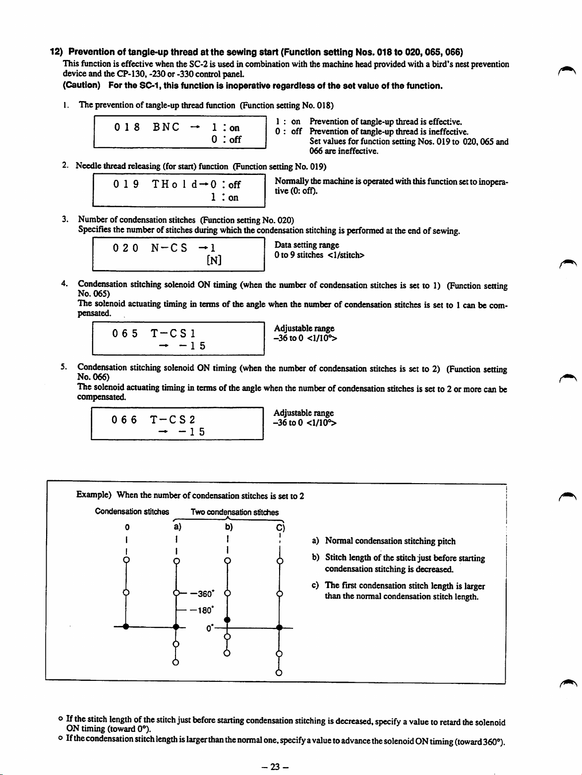
12) Prevention of tangie-up
This function is effectivewhenthe SC-2is used in combination with themachine headprovidedwith a bird's nestprevention
deviceand theCP-130, -230or -330 controlpanel
(Caution) For
the
SC-1,
threadatthe
this
function Is inoperative
sewing
start
(Function
regardlessofthe
setting
set
Nos. 018 to 020,065,066)
value of
the
function.
I. Thepreventionof tangle-up thread
2. Needle
018
thread
0
releasing
19
BNC
(forstart)
THo
1
function
function
d-0
1 I
0
1 !
on
:off
(Function
Icff
on
(Function
settingNo.018)
1 : on Prevention of tangle-up thread is effective.
0 : off Prevention of tangle-up thread is ineffective.
setting
Normally
tive (0: ofO.
3. Numberofcondensation stitches (Function settingNo. 020)
Specifies
4.
Condensation
No. 065)
The solenoidactuating
pensated.
5.
Condensation
No. 066)
The
compensated.
the
020
065
solenoid
066
numberofstitches
N-CS
stitching
stitching
actuating
solenoidONtiming
timing
T-CSl
^-15
solenoidONtiming
timinginterms
T-CS2
- - 1 5
during
which
the
condensation
^1
[N]
(when
Data setting range
0to9
the
numberofcondensation
in tenns of the anglewhenthe
Adjustable range
-36to0
(when
the
numberofcondensation
ofthe
angle
when
Adjustable range
-36to0
Set values for function setting Nos. 019 to 020,065 and
066
are
ineffective.
No.019)
themachineisoperated withthisfunctionsettoinopera
stitchingisperformed
stitches
the
<l/stitch>
number
of condensation stitches is set to 1 can be com
<1/10®>
numberofcondensation
<1/10®>
atthe
stitches
stitches
stitches
endofsewing.
is set to 1)
is set to 2)
is set to 2 or
(Function
(Function
more
setting
setting
canbe
Example) When the numberofcondensation stitches is set to 2
Condensation
o If
the
stitch
ON timing (toward
oIf
the
lengthofthe
condensation
0
1
I
O
stitches
stitch
0®).
stitch
lengthislarger
a)
I
I
Q
9
just
Two
condensation
360*
180'
0*-
before
than
-*•
b)
I
0
starting
the
normal
stitches
C)
I
i
condensation
one,
specifyavaluetoadvance
-23-
a) Normalcondensation stitchingpitch
b) Stitch
c) The first
stitchingisdecreased,
length
ofthestitchjust before
condensation stitching is decreased.
condensation
than the normalcondensationstitchlength.
stitchlengthis larger
specifyavaluetoretard
the
solenoidONtiming
starting
the
solenoid
(toward360®).

13}
Intermediate reverse stitchingfunction (Functionsetting Nos.030to
Thestitch
mountedcmthe
1. Intennediatereversestitching function (Function settingNo.030)
2.
3.
number
limit
and
thread
machine
Numberof intermediate reverse stitches (Function setting No. 031)
Specifies the number of intennediate reversestitches.
Conditions
Selects
state.
requiredtomake
whether
(Caution)
Thread
trimming
Enables
automatic
head.
OBT
N-OBT
the
intermediate
OBTS
The
intermediate
regardlessof the setting of No.032.
functioninaccordance
thread
OBTT
trimming
the
reverse
-0
trimming
—0
command
0
:off
intermediate
stitching
:off
1 I
on
reverse
stitching
with
after
the
:off
functions
reverse
functioniseffectiveorineffective
canbe
0 :
off
1 : on Intermediatereverse stitching function is effective.
Datasetting range
0to19
stitching
0 : off The intermediatereverse stitching functionis ineffective
1 : on The intermediatereverse stitching function is effective
Normal back tacking function
stitches
function
when the sewing machine is in the stop state.
even when the sewing machine is in thestopstate.
functioniseffective
the
intermediate
completionofintermediate
reverse
0 : off Threadtrimmingis not performed.
1 : on Thread trimming function is effective.
added
<l/stitch>
effective
stitching
reverse
tothe
while
033)
one-touch
(Function
while
the
(Function
stitching.
type
setting
the
sewing
sewing
setting
reverse
stitching
No.
032)
machine
switch
isinthestop
machineisrotating
No.
033)
Application
1.
Used
for
2.
Usedasa
specified.
Appli
cation
o
o
e
o
0
0
0
0
0
A
sewing
reinforcement
thread
trimming
Function setting
No.
030
(OBT)
OFF
ON
ON
ON
ON
Usedasthe
Used
for
rotating.) . . u •
Used
for
operatingor not.) . , .
Usedasthe
No.
(OBTS)
ONorOFF
OFF
OFF
one-touch
sewing
reinforcement
sewing
start
operatedbydepressing
Especially
Used
asthe
useful
start
operatedbydepressing
not.
Especially
useful
stitches
switch
for
type
No.
(OBTT)
ONorOFF
OFF
OFF
ON
ON
reverse
032
ON
ON
stitches
reinforcement
switch
when
switch
when
stitches
for
reverse
the
back
the
machineisused
for
reverse
the
back
the
(retaining
the
033
stitches)onpleatsifthe
sewing
machine
The
manual count-down function will not operate.
If the
one-touch
partofthe
stitches
If the
machine
machine
ction setting No. 031.
If
the
partofthe
stitches of the number specifled for function setting No. 031, then
performthe trimming.
If the
machine
machine
ction
setting
stitching
switch
(retaining
(retaining
stitching
partofthe
stitching
partofthe
machineisused
(for
foot
for
(for
foot
thread
tnmmmg
for
standing
type
foot
ofthe
one-touch
one-touch
one-touch
pedal
number
sew
type
foot
restorthe
No.031,
for
normal
type
reverse
pedal
type
reverse
is at rest or the front part of the foot
will
isat
willsew
stitches)
stitches)
end).
(Usedtoactuate
pedal.
Effective
standing
pedal.
work.)
end).
(Usedtoactuate
Effective
for
standing
reverse
specified
reverse
then
for
pleats.
for
pleats.
work.)
reverse
reverse
work
when
Outputfunction
stitching
depressed,
for
stitching
feed
stitches
stitching
depressed,
reverse
stitching
front
partofthe
feed
stitches
perform
stitching.
(Operates
(Operates
the
only
when
the
whether
the
switchisoperated
the
machine
function
switchisoperated
of the
switchisoperated
the
machine
of the number
thread
onlyaslongasthe
whether
thread
the
sewing.machineisin
thread
the
sewing
functionisnot
thread
trimming
with
will
sew
setting
number
will
switchisoperated
foot
pedalisd^ressed,
trimming.
the
trimmer
trimmer
reverse
No.
031.
pedal
depressed,
specifled
with
sew
reverse
specifled
machine
....
whichisnormally
whichisnoimally
machineisoperating
specifled.
function
while
while
machine
is
the
front
feed
the
the
for fun
the
front
feed
the
the
for fun
is
is
,i
operation.
or
-24-
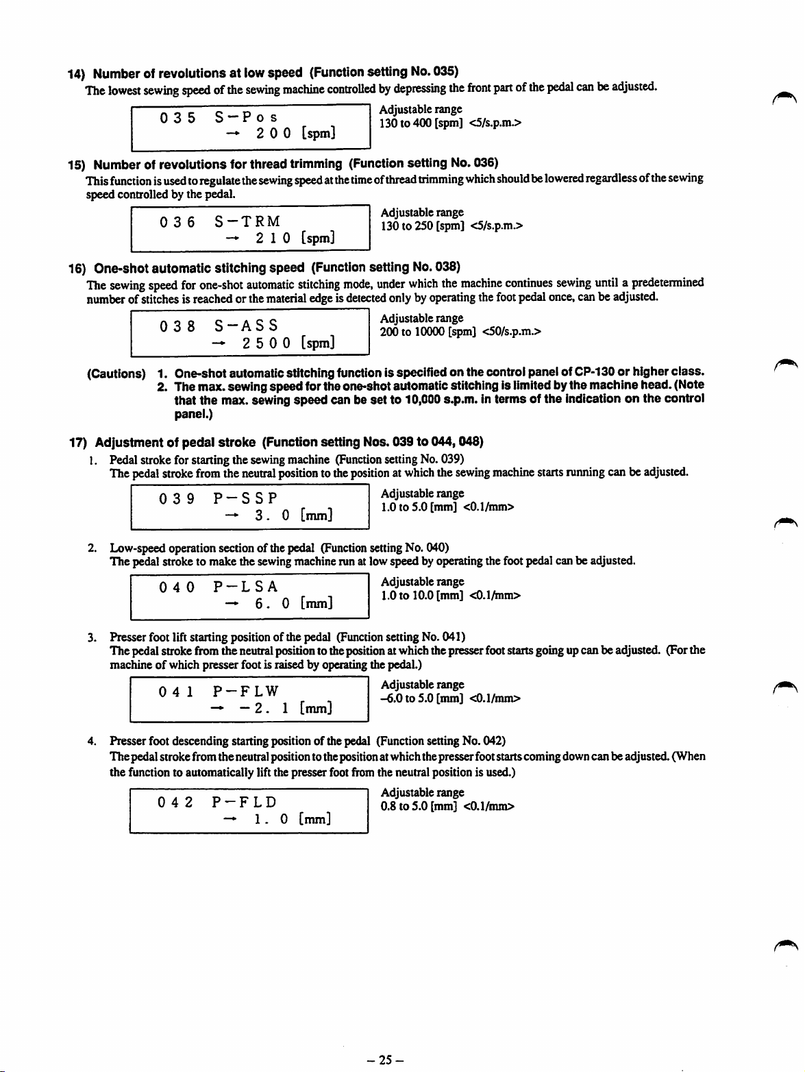
14)
Number
The
ofrevolutions at
lowest
sewing
speedofthe
035
low
speed
sewing
machine
S —
Pos
— 2 0 0 [spm]
(Function
setting
controlledbydepressing
Adjustablerange
130 to 400 [spm] <5/s.p.m.>
No.
035)
the
front
15) Number of revolutions for thread trimming (Function setting No.036)
This
functionisusedtoregulate
speed controlled by the pedal.
0 3 6
S-TRM
— 2
the
sewing
10
speedatthe
[spm]
timeofthread
trimming
Adjustable range
130 to 250 [spm] <5/s.p.mJ>
which
partofthe
pedal
shouldbelowered
canbeadjusted.
regardless
ofthe
sewing
16) One-shot automatic stitching speed (Function setting
The
sewing
speed
for
one-shot
numberofstitchesisreached
038
automatic
orthe
material
S-ASS
— 2 5 0 0
stitching
mode,
edgeisdetected
[spm]
No.
038)
under
which
the
machine
onlyby
operating
Adjustable range
200 to 10000 [spm] <50/s.p.m.>
the
continues
foot
pedal
(Cautions) 1. One-shot automaticstitchingfunctionis specified on the controlpanel of
2. The max. sewing speedfor the one-shot aiJtomaticstitching is limited by the machine head. (Note
that the max. sewing
panel.)
speed
can be set to 10,000s.p.m. in terms of the indication on the control
17) Adjustment of pedal stroke (Function setting Nos. 039 to 044,048)
1. Pedal strokefor startingthe
The
pedal
stroke
from
039
2. Low-speed operationsectionof the pedal
The pedalstroke to make the sewingmachinerun at lowspeed by operatingthe foot pedal canbe adjusted.
040
3. Presser foot lift starting positionof the pedal (Functionsetting No. 041)
Thepedalstrokefromthe neutralposition totheposition atwhichthepresserfootstartsgoingupcan beadjusted. (Forthe
machineofwhich presserfoot is raised by operating the pedal.)
041
—•
sewing
the
neutral
P-SSP
—
3.0
P-LSA
—
6.0
P-FLW
—2 . 1 [mm]
machine
position
[mm]
[nun]
(Function
tothe
positionatwhich
(Function
settingNo.039)
Adjustable range
1.0 to 5.0 [mm] <0.1/mm>
settingNo. 040)
Adjustable range
1.0 to 10.0 [mm] <0.1Anm>
Adjustable range
-6.0
to 5.0
the
[mm]
sewing
<0.1/mm>
machine
once,
starts
sewing
untilapredetermined
canbe
adjusted.
CP-130
running
or higher class.
canbe
adjusted.
Presserfoot descending starting position of the pedal (Function setting No. 042)
The pedal stroke from the neutralpositionto thepositionatwhich thepresser footstartscomingdowncan be adjusted. (When
the function to automatically lift the presser footfromthe neutral position is used.)
042
P-FLD
—1.0
[mm]
Adjustable range
0.8 to
5.0
-25-
[mm] <0.1/inm>

Pedalstroke 2 formakingthe threadtrimmerstart
Thepedalstroke
from
the
neutral
position
(Function
to the
positionatwhich
settingNo.043)
the
thread
trimmer
adjusted. (For the machineof whichpresserfoot is raisedby operatingthe pedal.)
P-TRM2
Adjustable range
-6.0
to 1.0 [mm]
<0.1/mm>
stans
trimming
the
thread
can be
Pedalstrokefor makingthe
The
pedal
stroke
from
P-MAX
Pedal
stroke
1for
making
The
pedal
stroke
adjusted.
-7
-6
No.
No.
No.
•Oar
•n 3
-5
from
(For
the
machineofwhich
P-TRMl
25^
w CO
n>
^
&
I*
3
o _
S.
-4
bT <0
-3 -2
0 CO
Directioninwhich
back part of the pedal
isi
48
43
41
the
the
machine
neutral
the
thread
neutral
5S5
Q. ® '
-n.
CO
the
O C
o g
a
3-
-1
> I
position
reachthe
trimmer
position
presser
(^0-4|)
IIIsS-5
O O p •
—fiS
"88®Q-I1
S=£-
g-"«3CO
£321
o ?
e
£
1
•o z
S.|
I
= -4
0
1
o "4
largest
number
tothe
positionatwhich
start
(Function
tothe
positionatwhich
footisraisedbyoperating
ofrevolutions (Function settingNo.044)
the
max.
sewing
Adjustable range
1.0 to 15.0 [mm]
setting
No.
the
<0.1/mm>
048)
thread
the
standard
Adjustable range
-6.0
to 1.0 [mm]
<0.1/mm>
(^0.3^)
S
3 2
3 o
o
»
a.
m
Low-speed
section
1 2 3 4 5 6 7 8 9
Direction
of the pedal Is
No.
inwhichthe front part
depressed
42
The sewing
depressing
-4
No.
39
No.
40
No.
44
speedisreached
trimmer
stans
hand-lifterorthe
speed
depthofthe
10
canbe
trimming
corresponds to
pedal.
11
12
13
Adjustable
the
knee
the
range
adjusted.
thread
switch.)
o S
o> o
O X
o*
Q.
14
0>
9
5"
CO
<n
0
15
(mm)
canbe
(Caution)
The
set
positionsshownaboveare intended forthe
DDL-5550.
-26-

18) Compensation of the neutral point of the pedal (Function setting No. 045)
Indicates
specifiedusing the functionto automaticallycompensate the neutral positionof the pedal.
Automatic compensation of the
neutral position
the
compensating
0 4 5
of
the pedal
valueof the
P-ANP
- 0
neutral
point
ofthe
pedal.
Adjustable range
-15to15
Compensating
value
ofthe
neutral
pointof the
pedal
is
Pressing4[SET]
a compensating value is indicated on the section on LCD
panel 9
additionally input as a compensating value.
(Caution) If
045
P-ANP
—
2
*♦*
1 2 3
(••0
T A
o
kt
19) Function of auto-lifter (Function setting Nos. 046,047,049)
I. Selectionof the auto-lifter (Function settingNo.046)
Selectseither the solenoid-controlledauto-lifteror the pneumatic auto-lifter.
0 4 6 F L s e 1 — 0 *
Length
oftimeduringwhichthe presser
Forthe
justed.
Forthe
specified.
solenoid
pneumatic
047
typeauto-lifter
auto-lifter
T-FL
(No.
046 0: sol),the
(No.
046 1:air),the
1 I
sol
air
foot
isheldraised
0 : sol Solenoid type (provided with the function to control
the
raised)
Operating voltage: 31 Vdc
1 : air Pneumatic type (not provided with the function to con
trol the lengdi oftime during which the presser foot is held
raised)
Operating voltage:24Vdc
(Function
length
oftime
presser
footis
raised
Adjustable range
600
60 to
sec [10/sec.]
6 0 [sec]
switchO,turnONthe
located
on the left of the switch. Now,the valueis
the
pedal
ing
chine
to
place
rest
lengthoftime during which the presser foot is held
Is held
the
aforementioned
will
not
operate
anything
your
footonit.
(At
the
of attraction) the presser foot
power
depressed
procedure,
properly.Besure
on
the
pedai
time
12Vdc
(At
is
held
switch.
when
the
perform
the
and
time
raised)
Then,
not
when
setting No.047)
during
which
aslongas
thepresserfootisheld
desired
regardless of the
raised
length
canbead
oftime
ma
not
to
3.
Length
of time during
No.
049)
The length of time during which the rotationof the sewing machine is prohibitedafter the presser foot has comes down until
the sewing machine starts rotating can be adjusted.
0 4 9
T-F
which
-*•
the
LWT
14
rotation
of the
0 [msec]
machine
is prohibited
Adjustable range
0 to
200
while
[msec] <10/msec.>
the presserfoot is descending
(Caution) If the specified length of time is insufficient, the sewing machine will start rotating before the
presser
footisfully lowered. This will
-27-
resultinuneven
material feed
and
slip-off of
(Function
the
thread.
setting
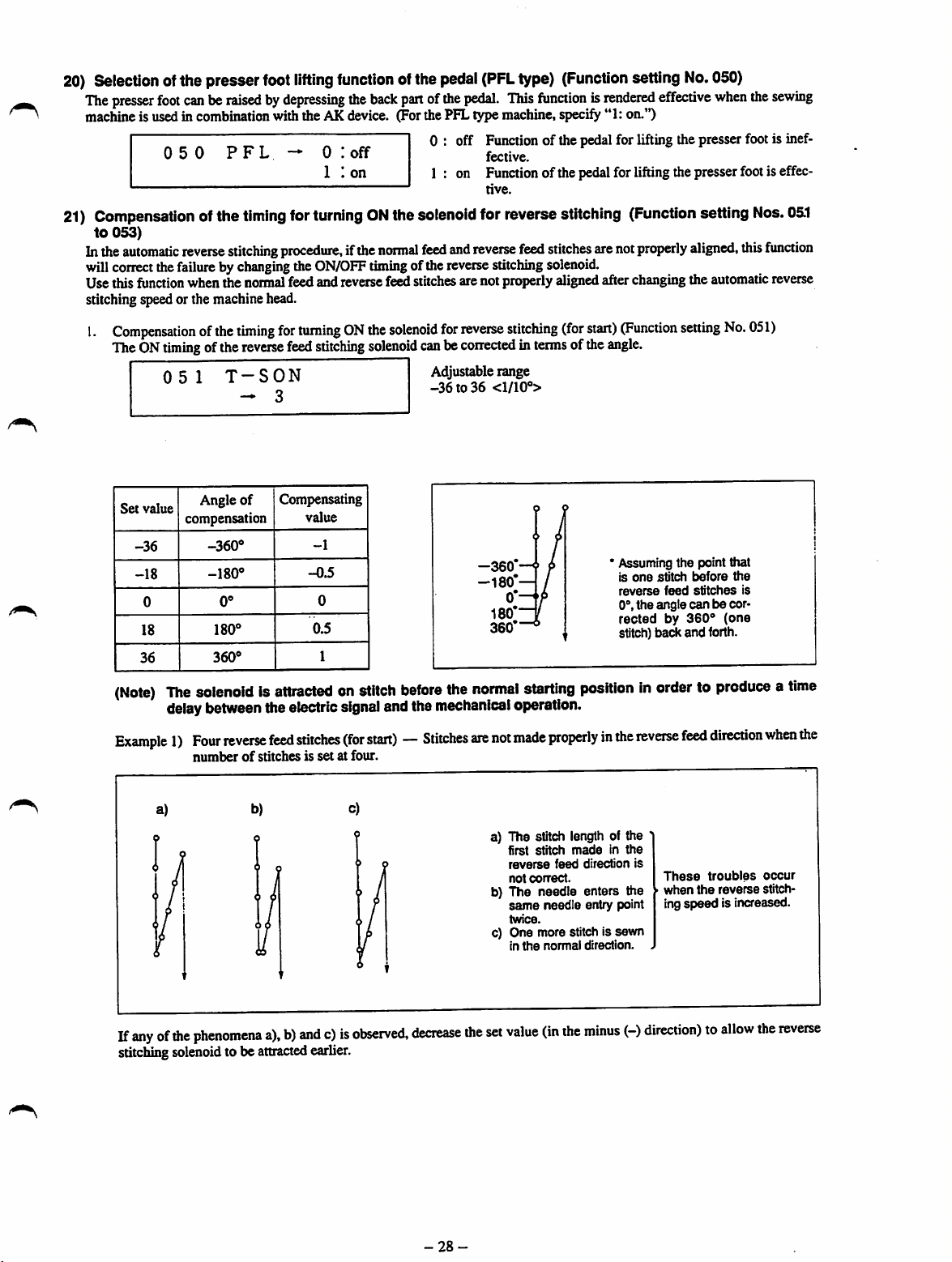
20)
Selection
The
presser
machineis usedin combination with the AK device. (For the PFL type machine, specify "1: on.")
21)
Compensation
to
053)
Inthe
will
correct
Usethis
stitchingspeedor the machinehead.
1.
Compensationofthe
TheONtiming
ofthe presser
foot
050
automatic
the
function
0 5 1
foot
lifting
canberaisedbydepressing
PFL
1
ofthe
timing
00
o
0
reverse
stitching
failurebychanging
whenthe
normal
timing
ofthe
reverse
T-SON
- 3
0 :
1 I
for
turningONthe
procedure,
the
ON/OFF
feedandreversefeedstitches arenotproperlyalignedafterchanging the automatic reverse
for
turningONthe
feed
stitching
function
the
back
off
on
ifthe
normal
timing
solenoid
ofthe
pedal
(PFL
type)
(Function
partofthe
ofthe
solenoid
pedal.
This
functionisrendered
0 : off Functionof the pedal for lifting the presser footis inef
1 : on Functionof thepedalfor liftingthe presser footis effec
solenoid
feed
canbecorrectedinterms
Adjustablerange
-36to36
fective.
tive.
for reversestitching
and
reverse
reverse
for
reverse
feed
stitching
stitching
<1/10°>
stitches
solenoid.
(for
start)
ofthe
arenot
setting
(Function
properly
(Function
angle.
No.
effective
setting
aligned,
setting
050)
when
No.
the
Nos.
this
051)
sewing
05.1
function
Set
value
-36
-18
0
18
36
(Note)
Angle
compensation
-360®
-180®
The
solenoidisattractedonstitch
delay
between
Example1)Four
numberofstitchesissetatfour.
a)
of
0®
360®
reverse
Compensating
theelectric
feed
b)
value
-1
-0.5
0
0.5
1
stitches
signal
before
andthe
(for
start)—Stitches
c)
-360'
-180*—
the
normal
mechanical
axe
not
a) The stitch length of the
b) The needle enters the
c) One more stitch is
starting
operation.
made
properlyinthe
first
stitch
reverse
feed
not
correct.
same
needle
twice.
in
the
normal
' Assuming the point that
is
one
stitch
before
reverse
feed
0°,the angle
rectedby360°
stitch) back and forth.
stitches
can
the
is
be cor
(one
positioninordertoproduceatime
reverse
feed
madeinthe
direction
entry point
sewn
direction.
direction
is
These
troubles
when
the
ingspeed is increased.
reverse
when
occur
stitch
the
If
anyofthe
stitching
phenomena
solenoid
to be
a),b)andc)is
attracted
earlier.
observed,
decrease
-28-
the
set
value
(in
the
minus
(-)
direction)toallow
the
reverse

Example 2)
Four
reversefeed stitches (for start) — Stitches are not made properly in the nonnal feed direction when the
numberofstitchesissetatfour.
a)
O i C 0 9 /
b)
/
00
' 4 i /
o
0
/ 1 9
1
/
These
troubles
a),b)andc)occurwhenthe
O /
c)
(
1 9
K
reverse
plus(+)direction)to allowthe reversestitching
Compensation
The
OFF
0 5 2
Set
value
-36
-18
0
18
36
ofthe
timing
ofthe
T-SOFF
- 1 2
Angle
compensation
-360®
0®
00
7
360®
timing
of
o
O
for
reverse
Compensating
turning
feed
value
-1
-0.5
0
0.5
1
OFF
stitching
the
solenoid
stitching
solenoid
solenoid
canbe
Adjustable range
-36to36<l/10''>
a) The stitch length of the fourth stitch
madeinthe
not
b)
The
entry
c)
One
direction.
speedisdecreased.
correct.
needle
point twice.
more
stitchis
reverse
feed
enters
the
sewninthe
Inthiscase,
to be attracted later.
for
reverse
stitching
correctedinterms
(for
ofthe
start)
direction
same
(Function
angle.
needle
reverse
increase
is
theset
setting
value
No.
(inthe
052)
Example1)Four
a)
If
anyofthe
ing solenoid to be attracted later.
reverse
feed
stitches
(for
numberofstitchesissetatfour.
b)
phenomena
a),b)and
c)is
observed,
start)—Stitches
c)
increase
-29-
are
not
made
properlyinthe
a) The stitch length of the last
stitch
madeinthe
directionisnot
b) The
needle
needle entrypoint
c)
The
numberofstitches
smaller than the specified
value by one. (One stitch is
includedinfree stitches.)
the
set
value
(in
enters
the
reverse
correct.
twice.
plus
the
(+)
reverse
feed
same
is
direction)toallow
feed
These
wften
the
ing
speed
decreased.
direction
troubles
reverse
is
the
reverse
when
occur
stitch
stitch
the

Example 2) Four reverse feed stitches (for start) — The number of stitches made in the normal feed direction is larger
than the specifiedvalue by one when the numberof reverse feed stitchesis set at four.
a)
b)
00
o
o
In this case,decrease the set value (intheminus
3.
Compensation
TheOFF timingof the
053
Set
value
-36
-18
0
18
36
ofthe
timing
reverse
T-EOFF
Angle
of
compensation
-360"
-180"
0"
360"
for
turning
feed
stitching
Compensating
value
-1
-0.5
0
0.5
1
a) The stitch length of
firstof free stitching is not
correct.
b)
The
needle
needle
enters
entry point
(forend)
OFFthe
same
twice at the sewing
c)
One
stitchoffreestitching
is
madeinthe
direction.
(-)
direction)to allow the reverse stitchingsolenoidto be attractedearlier.
solenoid
for
reverse
stitching
solenoid canbe correctedin termsof the angle.
Adjustable range
-36to36
<1/10°>
end.
reverse
the
the
(Function
These
when
ing
troubles
the
speed
setting
occur
reverse
stitch
is increased.
No.053)
Example1)Four
a)
Inthiscase,
reverse
the
specified
decrease
feed
stitches
value
whenAenumberofstitches
b)
thesetvalue(inthe
(for
end)—The
c)
minus
numberofstitches
a)
b)
c)
(-)
direction)toallow
-30-
issetat
madeinthe
four.
The
stitch length of
first
stHch
normal
rrat
The
same
twiceatthe
point of
reverse
The
madeinthe
direction is largerthan
specified value.
madeinthe
feed
correct.
direction
needle
enters
needle
entry point
change-over
the
normal
feed
directions.
numberofstitches
reverse
the
reverse
normal
the
is
the
and
feed
the
stitching
feed
These
when
ing
speed
increased.
solenoid
directionislarger
troubles
the
tobe
reverse
is
attracted
occur
stitch
than
earlier.
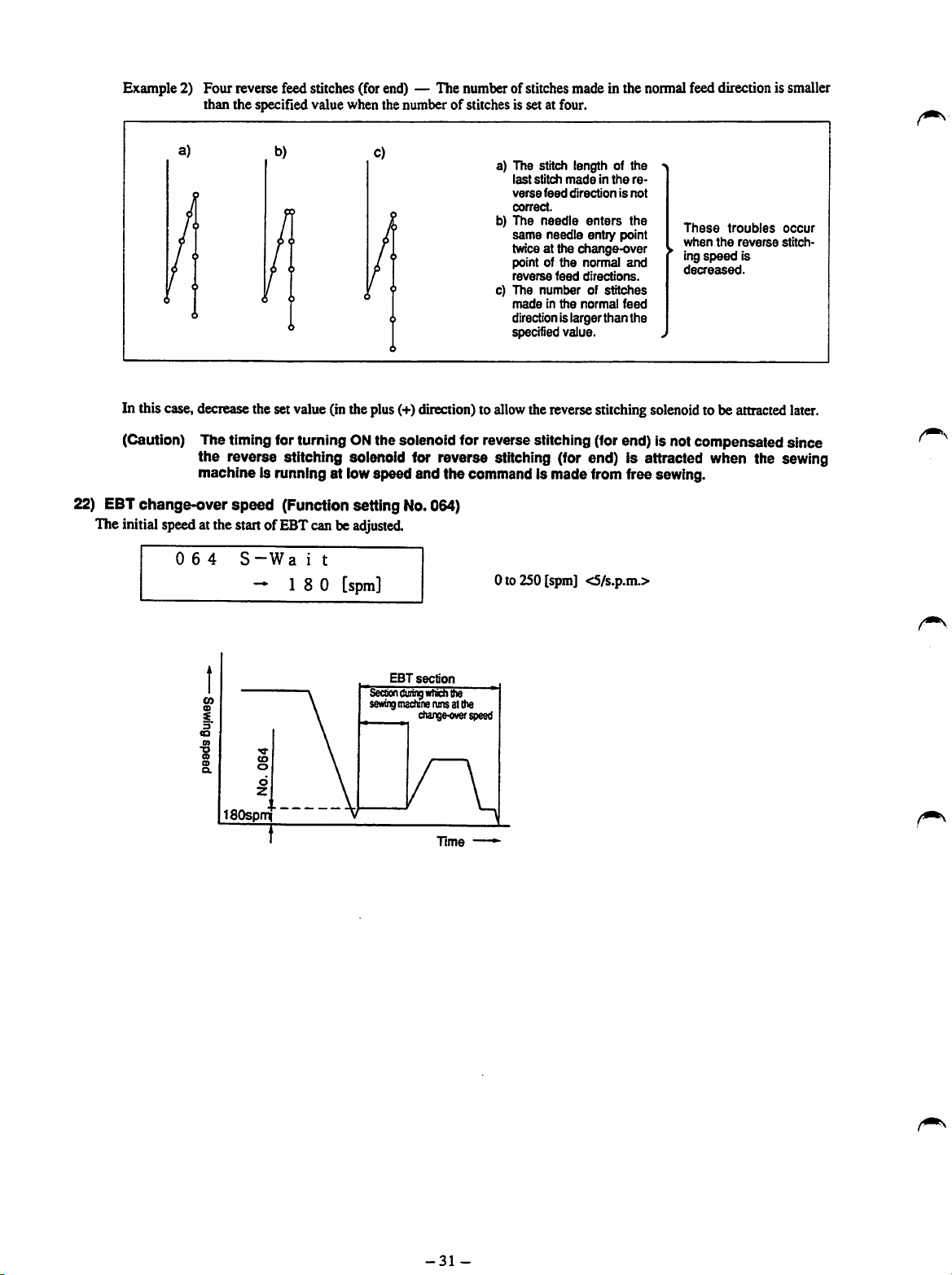
Example 2) Four reverse feed stitches (for end) — The number of stitches made in the normal feed direction is smaller
than the specified value when the numberofstitches is set at four.
In this case,decreasethe set value (inthe plus(+)direction) to
(Caution) The timing for turning ONthe solenoid for reverse stitching (for end) is not compensated since
the
reverse stitching solenoid for reverse stitching (for end) is attracted when the sewing
machine is running at lowspeed and the command is made from free sewing.
22) EBT
changeover
speed
(Function setting No.064)
The initial speedat the startofEBTcan be
0 6 4 S
~W
a i t
18
0
adjusted.
[spm]
a) The stitch length of
last
stitch
verse
correct.
b)
The
same
twice at the
point of
reverse
c) The
madeinthe
directionis larger
specified value.
allow
0to250[spm]
madeinthe
feed
directionisnot
needle
enters
needle
entry point
change-over
the
normal
feed
directions.
numberofstitches
normal
than
thereversestitching
<S/s.p.m.>
the
and
feed
the
the
re
These
when
ing
decreased.
solenoid
troubles
the
speed
reverse
is
occur
stitch
to be attracted later.
ISOspmi
EBT
Section
sewing
section
during
machine
change-over
which
runsatthe
Time
the
speed
-31
-

23) Effective diameter of motor pulley (Function setting No.054)
SpeclHesthe size of motor pulley (effectivediameter)used.
0 5 4
PCDMP
-
10
5 0 [mm]
Data setting range
40.0
to 200.0 [mm]
<0.5/mm>
(Caution)
24) Presser foot
This
machineisusedincombination
(FortheKFLorPFLtype
(Caution)Ifthis
1. Besuretospecifythe
ifthe motor pulley size Is not properlyspecified, maloperation
2. Thenumberengraved onthe motor
effective
(Effective diameter = Outside diameter - 5 mm)
lifting
functionisusedtoautomatically
055
functionIsmade
start of the
trimming.
25)
Reverse
The
Use
(Caution)
rotation
sewing
machineisrotatedinthe
this
functionifthe
0 5 6
Since
the
needle
effective
diameterofthe
function afterthread
liftthe
with
theAKdevice.
machine,
FLAT
setthis
effective
sewing
Besure to
function
needle
RATRM-0
needle
eyelet.
machine
specify
for
raising
reverse
protrudes
barIsraised
So,
properly
under
diameterofmotor
motor
pulley
pulley.
trimming
presser
foot
function
0 :
1 I
off
on
to"1:on.")
when
the
willbemomentarily
"0:
off"
when
the
needle
directiontoraise
the
presser
foottocatch
:
off
1 I
on
near
adjust
the
the
lengthofthread
pulley
whenever
indicatestheoutside diameter. So,besure tospecifythe
(for
KFLorPFL
after
thread
trimming.
0 : off
1 : on
sewing
Automatic
Automatic
machine
retarded
the
machine
after
thread
the
needle
the
0 : off Reverse rotation function for raising the needle after
threadtrimming is ineffective.
1 : on Reverse rotation function for raising the needle after
threadtrimming is effective.
highest
dead
type)
presserfootliftingfunctionis ineffective.
presserfootlifting
Isnot
when
is not
trimming
bar
near
sewing
product
point,
remaining
the
motor
will
result.
(Function
This
functionisrendered
equipped
depressing
equipped
with
(Function
the
highest
dead
when
sewingaheavy-weight
thread
willbelikelytoslip
after
thread
pulley
sizeIschanged,
setting
functioniseffective.
with
No.
effective
theAKdevice,
the
pedal
055)
after
theAKdevice.
setting
No.
056)
point.
off
trimming.
when
thread
material.
from
the
the
the
26)
27)
Needle
When
Reverse
1.
bar
theneedle
up/down
0 5 8
stitching
Auto^pedal-control
Selects
whether
oritis
performedatthe
059
(Caution)1.The
2.
Sewing
The
machine
machine
060
barisin
position
thehighest
HPo
(for
start)
change-over
the
reverse
stitchingisperformedata
sewing
SBTO
highest
function
2.
When
stop
canbetemporarily
setting
the
"Manu"isspecified,
function
SBTQ
retaining
positionorlowestposition,the
s
-^0
function
function
loff
1 I
function
on
(Function
for
reverse
(Function
0 : off
1 : on
setting
stitching
stretchatthe
speed
controlledbythe
Auto
-
Manu
reverse
stitching
No.
008
immediately
stopped
when
off
on
regardless ofthe
after
depressing
Auto :
Manu:Sewing
(for
start)
the
reverse
reverse
the
reverse
0 : off
1 : on
setting
brake
Needle
fective.
Needle
tive.
Nos.
(for
start)
Automatic
speedislimitedtothe
depressing
feed
stitching
stitching
Sewing
afterreverse stitching(forstart) is ineffective.
Sewing
afterreverse stitching(forstart) is effective.
No.
bar
bar
058)
up/down
up/down
position
position
isslightlyactuatedtoretain
059,060)
(Function
sewing
speed
depthofthe
speed
s^ing
specified
No.
for
pedal.
sewingat the specifiedspeed
changes
according
sewing
depthofthe
stitches
(for
start)
(for
start)isfinished.
machine
machine
will
(Function
pedal.
notbe
compensated.
setting
temporary
temporary
the
needleat
retaining
retaining
059)
the
function
tothe
speed
No.
060)
stop
stop
either
function
functioniseffec
setting
pedal
specified
function
function
immediately
immediately
position.
isinef
No.
008
operation.
for
the
-32-

28)
Auto/manual
Selectswhetherthe overlappedstitchingisperformedata stretchat the sewing speed specified for the function setting No.008
or it is performed at the sewing speed controlled by the depressing depth of the pedal.
changeover
function
for
overlapping
speed
(Function
setting
No. 082)
062
29) Direction of rotation of
Specifies the direction of rotationofthe motor.
0 7 5
BTOp
the
DM
motor (Function setting No. 075)
Auto
Manu
-
CCW
CW
Auto : Automatic sewing at the specified speed
Manu : Sewing speed changes according to the pedal operation.
CCW
CW
Counterclockwise
Clockwise
30) Accumulated length of time during which the sewing machine is energized (Function setting No.100)
Indicatestheaccumulated lengthoftime
1 0 0
STO
during
which
the
sewing
machine
isenergized in theunitof minutes.
— * * * [min]
31)
E^PROM
Returns
reset
the
respective
ITEM
(Function
fimctions
No.
1 0 1
setting
tothe
No.
initial
ResEEP
101)
state.
(The
fimctions
returns
from
the
changed
When the item No. 101 is shown on the LCD panel, execute the
function by simultaneously pressing the 3 [ITEM] switch and 4
[SET]switch. (Whilethefunctionisbeingexecuted,the sectionon
the right of the-♦blinks.)
state
tothe
initial
state.)
(Caution)
When
this
operationisperformed,
the
neutral
performautomatic compensation of the neutral position of the pedal.
32)
Monitor
Gives
33) Hysteresis of troubles (Functionsetting
Ifa
34) Communication
Receives/transmits data stored in the
ofthe state of input signal (Functionsetting No.102)
the
trouble
real-time
occurs,
indication
the
descriptionofthe
— E * *
EX
facility
ofthe
stateofinput
I T
(Function setting
trouble
*
PSC
box.
and
signals
No.
103)
the
Nos.
time
35) PSCboxversion management (Function setting
Be
suretocontact
our
V e r s
office
ion
after
checking
* * *
the
version
No.ofyour
position
ofthe
pedal
will
retum
(0/1).
(minute)
£
Description of trouble Time of occurrence
»♦
whenitoccurs
willbestored
inthe
105,107)
No.
108)
PSC
box.
.
TypeofPSC
-
Destination
•
Destination
PPROM
box1:Standard,
code
for
users
codeE:For
data
version
KFL
type4:PFL
EuropeF:For
to "0." So,be sureto
hysteresisoftroubles.
type
export
PPROM
CPU
-33-
masit
version
version

(4)
Examplesofapplications
1) Usedasan
detecting
Procedure)
material
function (ED: Optional).
Set
material
tion ( mark) 0 to the ON state.
edge
control device by
edge
detecting
means
function(<j(
of the CP-130 control panel
mark)
0 to
theONstate.
O 0
Set
and
one-shot
the
material
automatic
edge
stitching
func
ope,'
I A A
ABClIC
V V 1.
«—0—'
f..
(H)
l/l
l\l
N
<
—
B-
1 1 1 (
7^
C<D-s
1
+
1 1
1
—
A-
1 1
1
-
•JUiCI
CP-130
u
(§r
w
Caution)
The
one-shot
automatic
stitching
speed
canbechanged
nrnjlf
using
the
function
setting
No.
038.
-34-
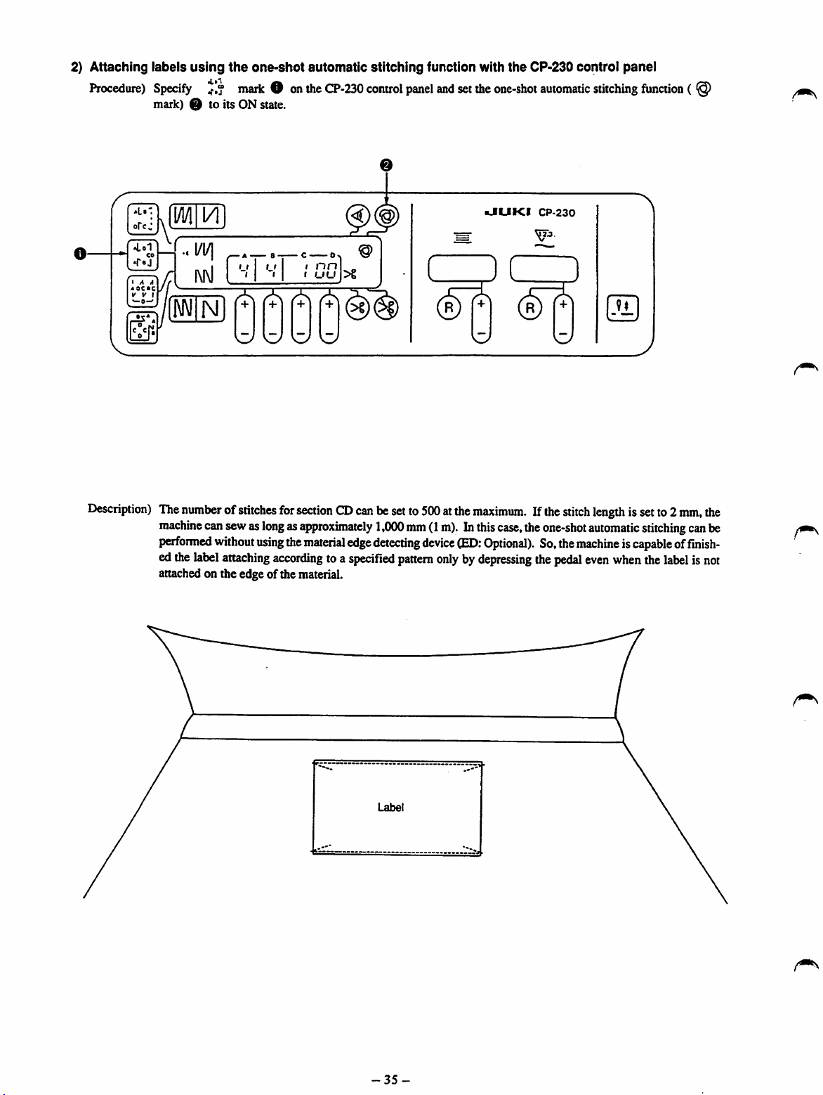
2}
Attaching
Procedure)
labels
using
the
one-shot
Specify
mark) Q to its ON state.
maiicOon
automatic
the
CP-230
stitching
control
function with
panel
and
set
the
one-shot
the
CP-230
automatic
control
stitching
panel
fimction
( @
I A A
AOCaC
V y I
W0-'
Description)
I
nri,^„
I
uu
The
numberofstitches
machine
performed
edthe
attached on the edge of the material.
cansewas
without
label
attaching
for
sectionQDcanbesetto500atthe
longasapproximately
using
the
material
according
toa
©
>6
edge
detecting
specified
1,000mm(1
device
pattern
kJLIKI
maximum.
m).Inthis
(ED:
case,
Optional).
onlybydepressing
CP-230
Ifthe
the
So,the
the
stitch
length
issetto2
one-shot
automatic
machineiscapableoffinish
pedal
even
when
stitching
the
label
mm,
can
is not
the
be
-35-

3) Sewing small
parts
effectively
using
the
CP-330 control panel.
Procedure) Specifycombined stitchingmode ^ O onthe CP-330controlpanel.
Example)
Attachingapocket
processes.)
witha penslitona work
uniform
(Single
unitof the
sewing
machineisused
in four
different
f I A A
«acBC
[CO.
: N
(1) Attaching a pocket
Input
pattern
Ato ^
«mO
—
UUKI
LM
*1—
1 1 1
CP-330
—
c-
it
—
u
I
g)@
>§
^Q(T)(g)
m
tu
--iD
(^(g)
L3
9f
W
(2) Attaching a flap
Input
Bto or |>
(3)
Welting
InputCto
Process
(1)-A•»
Data input sequence)
the flap
f^jilor|>.
sequence)
(2)-B-» (3)-C• (4)
*L»-:
opcj
' aL'". "
ofcj
1 A A
ABCSC
Y V 1
.-o--.
-D
(4) Sewingreinforcementstitchesfor a pen slit
D
InputD to y j .
1 A A
•»
ABCBC
Y Y 1
-36-
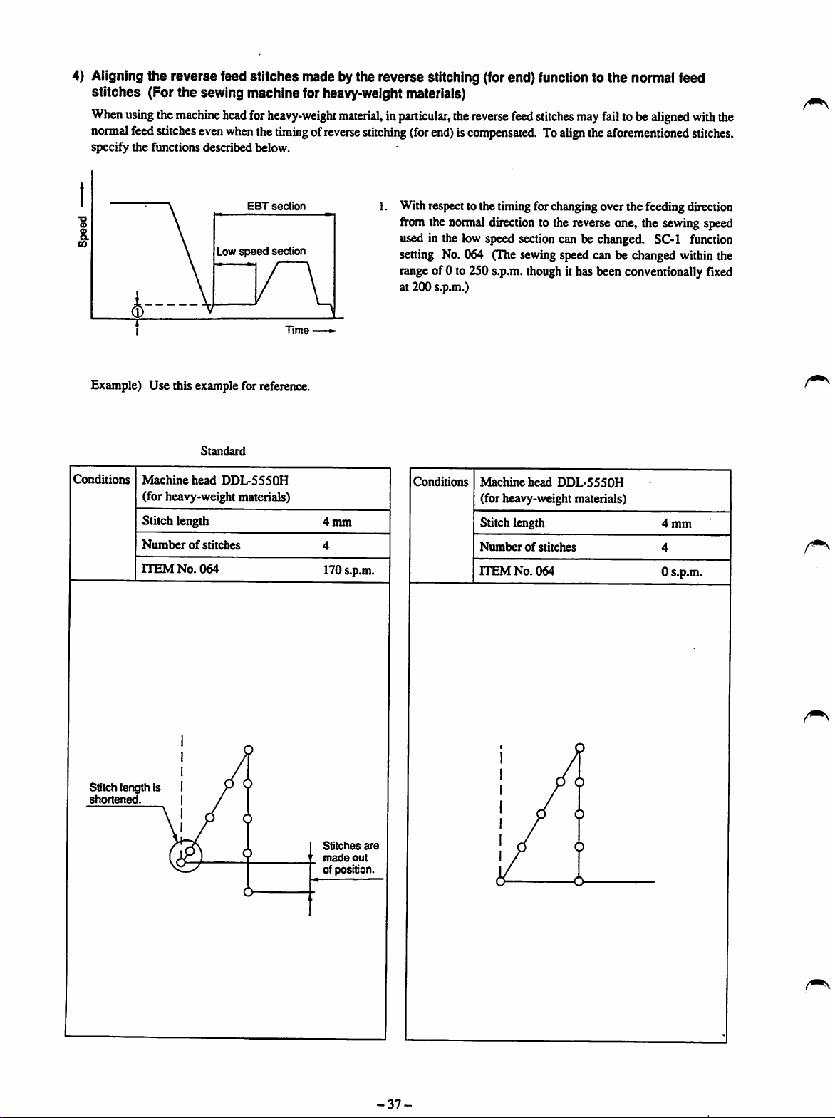
4) Aligning the reverse feed stitches made by the reverse stitching (for end) function to the normal feed
stitches (For the sewing machine for heavy-weightmaterials)
When
using
the
machine
normal
feed
stitches
specify the functions described below.
Example) Use this examplefor reference.
even
Low
Standard
head
when
for
heavy-weight
the
timingofreverse
EBT
section
speed
section
material,inparticular,
stitching
(for
the
reverse
feed
stitches
end)iscompensated.Toalign
may
fail
the
aforementioned
tobe
1. Withrespectto the timingfor changingover the feeding direction
fromthe
normal
direction
to the reverse one, the sewing speed
used in the low speed section can be changed. SC-1 function
setting No. 064 (The sewingspeed can be changed withinthe
rangeof 0 to 250 s.p.m.
at 200 s.p.m.)
though
it has been conventionally fixed
aligned
with
stitches,
the
Conditions
Stitch length Is
shortened.
Machine
head
DDL-5550H
(for heavy-weight materials)
Stitch length
Numberofstitches
rrEMNo.064
4mm
4
170 s.p.m.
Stitches
made
out
of position.
are
Conditions
Machine
(for heavy-weight materials)
Stitch length
Numberofstitches
ITEM
No.
head
064
DDL-5550H
4
mm
4
0 s.p.m.
-37-

5.
EXPLANATION
OF
ERRORS
AND CORRECTIVE
MEASURES
No.
EO
El
Descriptionand components to be checked
InitializationofdataonE
PROM
• Failed input power supply (openphaseofpowersupply)
Check whether the power plug
and receptacle have loosened
or
come
off.
Check the power plug for
failed
contact.
Check whether the power
switch
tenninal
or
come
off.
has
loosened
Corrective
measures
• Tighten the screw mounted in
the plug.
• Re-connect the plug to the re
ceptacle.
Correct the receptacle.
• Tighten the screw inside the
power switch.
E2
Checkwhether the
power
connectorpin has loosened
or
come
off.
Check whether the power
fiise
has
blown.
Motor connector has come off. (Themotor connection signal has not been
input in the nonnal value.)
Check
whether
the
motor
signalconnectorpin has
loosenedorcome
off.
•
Re-connect
Check
for blow-out.
blown out fuse,
new
one.
the
the
fuses
connector.
Fl,F2and
Then,
if
any, with a
replace a
(Only for the machine of 03
and220
V.)
•
-Re-connect
the
connector.
F3
(Caution)
r
-38-
The
errorisnot
storedinmemory
of
the
hysteresis
of
troubles.

No.
Description and components to be checked
Corrective
measures
E3
• V belt has slipped or comeoff. Synchronizerconnectorhascomeoff. (The
motor rotates, however, the upper/lower position detecting signal is not
input)
Checkwhetherthe synchronizer
oUiU(3U
connector
off.
rac
' J
has
loosenedorcome
Checkthe synchronizer for dis
connection.
•Jiumtggj
LJ
TmT
/l/\
)
Check
whether
come
off, loosened or slipped.
(Caution)
1
"1
e •
theVbelt
After
the
has
been
tected,
will
operateasa
clutch
without
trimming
tion.
the
has
error
de
motor
motor
thread
func
• Re-connect
the
synchronizer.
• Replace the synchronizer with
a
new
one.
Check
theVbelt.
(Belt tension: IS mm/kg)
(Caution)
The
troubleIsnot
storedinmemory
of
the
hysteresis
of
troubles.
E4 • The V belt has slipped,comeoff or the lowerpositionsensorhas
(The motor rotates, however, the lower detection signal of the machine
head is not input.)
RefertoE3.
E5 • The V belt has slipped,come offm*the upperposition sensorhas
E6 •
(The motor rotates,
head is not input.)
Failed
communication
however,
with
the
the
uj^r
RefertoE3.
control
detection
panel
(The
signal
sewing
of the
machine
lerhasfailedto communicate withthe controlpanel.)
Checkthe control panelcord for
disconnection.
the panel cord comes in contact
with
the V belt.)
Checkwhether thecontrolpanel
coimectorhas loosened. (Check
whether the control panel con
nector has been securely con
nected
to the machine.)
(Check
failed.
failed.
machine
control
whether
RefertoE3.
RefertoE3.
• Check the control panel cord
and
replaceitwithanew
necessary.
•
Re-connect
the
connector.
one,
if
-39-

No.
Descriptionand components to be checked
E7 • The motorhas locked. (The motorfails to rotate with controlled even when
the
motor
has
been
driven.)
Corrective
measures
Check whether the sewing ma
chine
head
has
locked.
(Is
possibletotumthepulleylightly
by hand?)
Check
whether
the
thread
has
been tangled in thepulley of the
sewing machine.
Check
whether
the
thread
has
beentangledinthemotorpulley
shaft.
Conea
it
chine
•
Remove
the
head.
the
seizureofthe
thread
from
ma
the
pulley.
Remove the pulley and elimi
nate the thread from the pulley.
•
Check
Check
whether
the
thread
has
the
been caught in the hook.
Check
whether
the
proper
amount of oil is supplied to the
hook.
-40-
Properly adjust the amount of
oil supplied to the hook.
hook.

No.
Description and components to be checked
E8 • The pedal connector has come off. (The pedal identification signal has
changed after turning ON the power to the machine.)
Check
whetherthe pedal sensor
connector
has
come
off.
•
Re-connect
Corrective
the
measures
connector.
E9
£10
m
• Failure of the pedal sensor (Coimection signal of the pedal has failed.)
• The solenoid has short-circuited. (Short-circuit signal has been detected
when
actuating the solenoid.)
The
machine
short-circuited.
The
solenoid
improperly wired.
head
solenoid
connector
has
has
been
(Caution)
The
troubleIsnot
storedInmemory
of
the
hysteresis
of
troubles.
• Replace the pedal sensorwith a
new
one.
•
Check
the
resistanceofthe
lenoid.
so
Check the wiring.
Check
The
Ell
transformer
• Overvoltage of thepowersupply (Thesourcevoltage
fuse
exceeds
has
blown.
thenormal
value.)
Check
whether
the
source
volt
Measure the voltage.
age is correct.
-41-
the
fuse
F4.

No.
E12 • Overcurrent of the power supply (The source current exceeds the normal
Description
and
components
to be
checked
• Overcurrentofthe
supply (The source current
exceeds
the
normal
power
value.)
Corrective
measures
E13
E14
Low voltageof the power supply (The source
normal
value.)
Check
age is correct.
Check
fiise
Power
supply
detecting
circuit
has
failed.
(Overvoltage
thepowersupplyaresimultaneously input.)
Check whetherthe regeneration
r*
fuse
E
voltage
is lower than the
•
whether
the
source
Measure
volt
the voltage.
whethertheregenerative : • Check thefuseF6.
has
blown.
and
low
voltage
of
Check
the
fuse
has
blown.
F6.
E20 • Circuit board inside the PSC box has failed. (Failurehas been found during
the
performance
machine.)
E22 • Failed control of the motor rotation (The number ofrevolutions of the motor
is
larger
value or more.)
Fr?3
E24 • MotorDRv
E26
• Solenoidtransistorisdefective.(Short-circuitsignalofthe solenoidtransistor
hasbeendetected whentumingONthe powertothe
input.)
•
Defective
power
supplyofthe
the
power
indicated
•
Failed
+24Vpower
than
power
value.)
checking
that
controlled
element
supply
tothe
machinetofind
procedure
has
failed.
ofthe
solenoid
supply
bythe
motor
(Errorsignal
solenoid
has
been
thatthe
(The
+24Vpower
RefertoE25.
taken
after
turning
control
from
(When
changedatthe
voltageisdefective
-
Check
has
ONthe
power
tothe
circuit
board
bya
specified
machine.)
theDRvelementhasbeen
the
output
voltage
of the
timeoftuming
against
whether
blown.
supply
the
transfer
has
short-circuited.)
ON
the
fuse
Check
the
fuse
F4.
RefertoE25.
-42-

No.
Description and components to be checked
E30 • Openphase of themotorencoder (Motor encoderprovidespulses belowthe
specified value.)
E31 • Openphase of themotor polesensor (A signalotherthan the acceptablein
put signalsofthe pole sensor has been
input)
E33 • Failed reverse rotation of the motor (The motor has rotated in the direction
other
than
the
one controlled.)
E41 • Micro-computerhasfailed. (Themicro-computer has failed to controlthe
peripheral components.)
Corrective
measures
E42
E43 •
•
E^PROM
Failed
(Failed
home
accesstothe
position
of the
memory)
bobbin
thread
remaining
amount
detecting
device [AE-4 or -S]. (The bobbin thread remaining amount detecting
solenoid has failed to retum to its home positionafter the actuation.)
The bobbin thread remaining
amount detecting device has
been removed from the sewing
machine by setting the ITEM
No
057totheONstate.
Check
whether
the bobbin
the
thread
connector
remaining
amount detecting device has
been securely connected.
Solenoidpin has come off.
•
Set
the
ITEM
OFF
state.
of
Connect
the
• Check the solenoid pin for se
cure
connection.
No.
connector.
057tothe
•
Check
whether
dustinthe
bobbin
thereisoil
thread
or
re
maining amount detecting
device.
Checkwhethertfaedetectingbar
has
lowered.
Check
whether
light
-43-
the
sensor
emits
Check whether the detecting
bar can be moved by hand.
Replace the bobbin thread re
maining amount detecting unit.
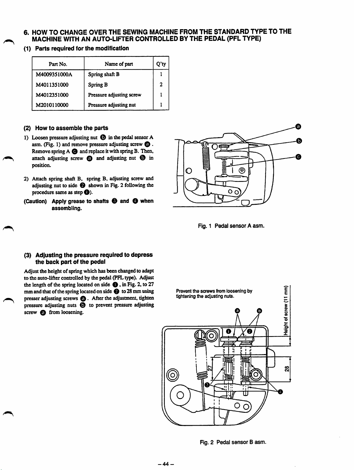
6. HOW TO CHANGE OVER THE SEWING
MACHINE
FROM THE STANDARD TYPE TO THE
MACHINE WITH AN AUTO-LIFTER CONTROLLED BYTHE PEDAL (PFL TYPE)
(1)
Parts
required
for
the
modiflcatfon
Part
No.
M4009351000A
M4011351000
M4012351000
M2010n0000
(2)
Howtoassemble
1)
Loosen
pressure
asm.
(Fig.
1)and
the
adjusting
remove
Removespring A 0 andreplace itwith
attach
adjusting
position.
2) Attach spring shaft B, spring B, adjusting screw and
adjusting
procedure sameas step
(Caution)
Apply
assembling.
screw0and
nuttoside 0
O).
grease to shafts 0 and 0 when
Name of part
Spring shaft B
Spring B
Pressure
Pressure adjusting nut
pressure
adjusting screw
parts
nut O inthe
adjusting
adjusting
pedal
spring
sensor
screw
B. Then,
nut
0 in
showninFig.2following
O •
the
Q'ty
1
2
1
1
A
Fig. 1 Pedal
sensor
Aasm.
(3) Adjusting
the
Adjust the height of spring which has beenchangedto adapt
to the auto-lifter controlled by the pedal (PFLtype). Adjust
thelengthof the springlocatedon side0,inFig.2, to 27
mmandthatofthespring
presseradjustingscrews
pressure
screw 0 from loosening.
adjusting
back
the
pressure
partofthe
located
0.
nuts 0 to
required to
pedal
depress
onside 0 to28mmusing
Afterthe
prevent
adjustment,
pressure
adjusting
tighten
Prevent
the
screws
tightening ttie adjusting nuts.
from loosening by
ZiMi
B
Fig. 2 Pedal
-44-
sensor
Basm.

(4)
Setting
Now,change the standard setting of functionsof the PSCbox to adapt to the PFL type.
Thesettingofthe followingtwofunctionsforthePFLtypemachinearedifferentfromthatforthestandardtype sewingmachine.
Sochangethe settingof thefunctions toadaptto thePFLtypereferringto theexplanation of the functions.
for
the
functionsofthe
PSC
box
1) Selection of
2) Presserfoot iifting function after thread trimming
050
050
0 5 5
0 5 5
the
presser
PFL
PFL
FLAT—
FLAT-
foot iiftingfunction using the pedal
0 :
off
1 !
on
-
1 !
on
Set
the
(ITEM
Set
the
ftmctionto"1:
No.055)
functionto"1:
0 :
0 :
1 !
1
0
off
off
on
:on
:off
(ITEM
No.050)
on.'
on.'
(5) Automaticcompensation of the neutral position of the pedal sensor
When
the
pedal
isinthe
neutral
position,
error
caused
during
assemblyiscorrected.
045
P-ANP
—
***
JL
7.
AUTOMATIC
PRESSER
cnno
FOOT
ntu
SCT
LIFTING
for the sewing machine equipped withthe
This
functionisusedtoautomatically
The
lengthoftime
automatically
ithasonce
Operating
during
ascend
moved
awayfromthe
procedure
after
which
thread
(••••
12
• A
liftthe
pedal
the
presser
foot
trimming.Ifthe
neutral
position.
3 4
ItCM
SO /
/
automatically
presser
P)
FUNCTION
when
itisin
foot
automatically
Pressing 4 [SET] switchO,turn ON the power switch. Then, a
compensatingvalueisindicatedonthe"***" sectiononLCDpanel
O
located
input as a compensating value.
(Caution) If
AK
device)
the
neutral
the
pedal is held
the
aforementioned
not
operate
thing on the pedal
FROM
THE
position.
goesupdependsonthe
comes
down,itwillgoup
1)
TurnONswitchOfor
position,that is located next to
box. [Once the switch is
switch will light up.]
ontheleftofthe
2) Toreleasethis
be
released
out.
function,
from
switch.
properly. Be
NEUTRAL
lengthoftime
lifting
pressswitch O again.Theswitchwill
the
locked
Now,
the
valueisadditionally
depressed
procedure,
and
nottorest
when performing
sure
POSITION
during
which
from
the
neutral
the
presser
foot
the
functionswitches on the
turned
ON,
the
monitor
stateandthe monitor
the
nottoplace
your foot on it.
the
from
machine
(Only
presser
position
the
neutral
LEDofthe
LED
willgo
any
will
foot
after
PSC
-45-

8.
HOW
TO
CHANGE
THE
SIZE
OF
MOTOR
PULLEY
Besureto changethesettingofthe motorpulleysizeonthePSCbox(function settingNO.054)wheneverthemotorpulleysizeis
changed.
Ifthemotorpulleysize isnotproperlyspecified,thecorrectnumberofrevolutions willnotbeobtainedandmaloperationwillresult.
Example) 0 l 10 mm (outside diameter)
diameter)
(1) Access to the service level referring to "4-1. Setting for
functions."
<=>
080 nun (outside
(2) Specify ITEM No. 054 bypressingthe 1 [•] switchor 2
[A]
switch.
(3) Press the 4 [SET] switch so that
changeofdata.
(4) Specify 75.0 [mm] using the 1
(Note)
(5) Press the 4 [SET] switch the enter the specified value.
(Caution) If
The
number
cates
the
obtained
diameter.
you
will
engravedonthe
outside
diameter.
by subtracting 5 [mm]from
(80-5=75mm)
omit
this
procedure,
not
replace
the
the
PSC box accepts a
[T]
switch.
motor pulley Indh
Effective
the
previous
diameter
the
outside
modified value
set
value.
Switch operation
(1)
: Indication on the LCD panel
(••00
1^.
0
DDL-5550
ITEM
NO.
CtDDD
(2)
(3)
(4)
is
(5)
1 2
•
or
(300
T • s«t|
(
DGOO
mm.
T A
•
ITEM
054
054
055
001
NO.
054
PCDMP
-•
105.0
PCDMP
-»
75.0
FLAT
-
N-SOFT
-
PCDMP
[mm]
[mm]
0 :
OFF
1
:0N
(6) TurnOFFthe powerto the
settingofthe motor pulley size is completed.
(7) Re-tumONthepowertothe
machine to the normal operation mode.
machine.
machine.
Nowthe
change
Thiswillretumthe
of the
(6)
(7)
DDL-5550
-46-

9.
EXPLANATION
(1)
Replacing
the
Fuse
OF
fuses
FUSES
I
vjjjjj
Open
the
front
cover.
Fit a
screwdriver
the fuse cap. Turn the cap in the direction of the
ing the screwdriver while lightly pressing the screwdriver
ontoslit O on
anow
us
11
against the slit until the cap comes off.
Use a fuse with a capacity indicated on a label attached on
section
(Caution) Be
© ofthe
suretoreplace
to
the
connector
machine
panel.
the
turned
fuse
OFF.
with
the
power
*
Fuse
F1
F2
F3
F4
F5
F6
Enlarged
/
table
30
220
250V
12A
Main
2S0V
12A
Main
250V
12A
Main
2S0VT
1.6A
Transfornier
250VT
1.6A
Rush-current
prevention
250VT
0.5A
Regeneration
abMrption
viewofsection©(The
F1
250V.
12A
V
Phenomenon
by blown out fuse
Elisindicatedonthe
display.
ElIsindicatedonthe
display.
Elisindicatedonthe
display.
E2S is first indicated on the
display,then E26 replaces
The
machine
energized.
El
3 is
display.
cannot
indicatedonthe
250V
caused
F2
be
12A
250VT
Main
250VT
Main
250VT
H.
Transformer
250VT1.6
Rush-current
prevention
250VT0.5A
Regeneration
absorption
10
I
figure
220V
20A
20A
1.6A
illustrates
F3
250V12A
10
250VT
Main
250VT
Main
250VT3.0
Transformer
A
250VT1.6
Rush-current
prevention
250VT0.5A
Regeneration
absorption
120
20A
20A
the
V
fuse
A
A
for
the
machineof03
F 4
250V.
T1.6A
Phenomenon
by blown out fuse
The
machine
energized.
The
machine
energized.
E25 is first indlcatBd on
display,
The
machine
energized.
El
3 is
display.
caused
cannot
cannot
thenE26 replacesit
cannot
indicated
onthe
250V.
be
be
the
be
and
220Vfor
F5
T1.6A
JE
type of 01
and
220V
—
—
—
250VT1.6A
Transformer
250VT1.6A
Rush-cunent
prevention
250
VT O.SA
Regeneration
absorption
general
export)
F6
250V.
T0.5A
Phenomenon
by blown out
E25 is first imficated on
display,then E26 replacesit.
The
machine
energized.
El
3 is
display.
caused
fuse
—
—
cannot
indicatedonthe
the
be
-47-

10.
CONNECTOR
CONNECTION
DIAGRAM
c.n.n.D
BS232C
D
0 0 0 0
TYPE
W Q
m
S:
e o
£ 5
ii
0
-""s
bra
1
T-
o 0
HTOT
0 0
CN32
o
CN61
0
CN62
0
CN63
0
CN64
0
CNIO
0
CNll
0
CN12
0
CNl
0
CN3
0
CN3
0
CN4
0
CN5
0
CN6
0
CN7
0
CN8
0
CN9
0
CN93
0
CN94
0
TP
14?
2?
10?
2?
6?
4?
2?
8?
16?
10?
4?
4?
5?
20?
12?
6?
2?
2?
(red)
(black)
Synchronizer
Machine
Presserfootliftingsolenoid
Solenoid valve (for SC-2 only)
24 V external output
Bobbinthread
head
solenoid
remaining
(Flyback
resistor
asm.
amountdetecting device
Externalswitchfor No. of pcs. counter(optional)
IPS,production controlsystem(optional)
RS232C
Pedal
sensor
Motor
Resistor pack
Sub-panel(notused at present)
CP-30 control panel
CP-130, -230, -330 control panel
Pedalfor
Material edge sensor(ED: Optional)
sewing
machine
for
standing
woric
(optional)
Lampfor 6 V (JEtype is excluded.)
Lampfor 12V (JE type is excluded.)
isnotrequired.)
(AE:
Optional)
-48-
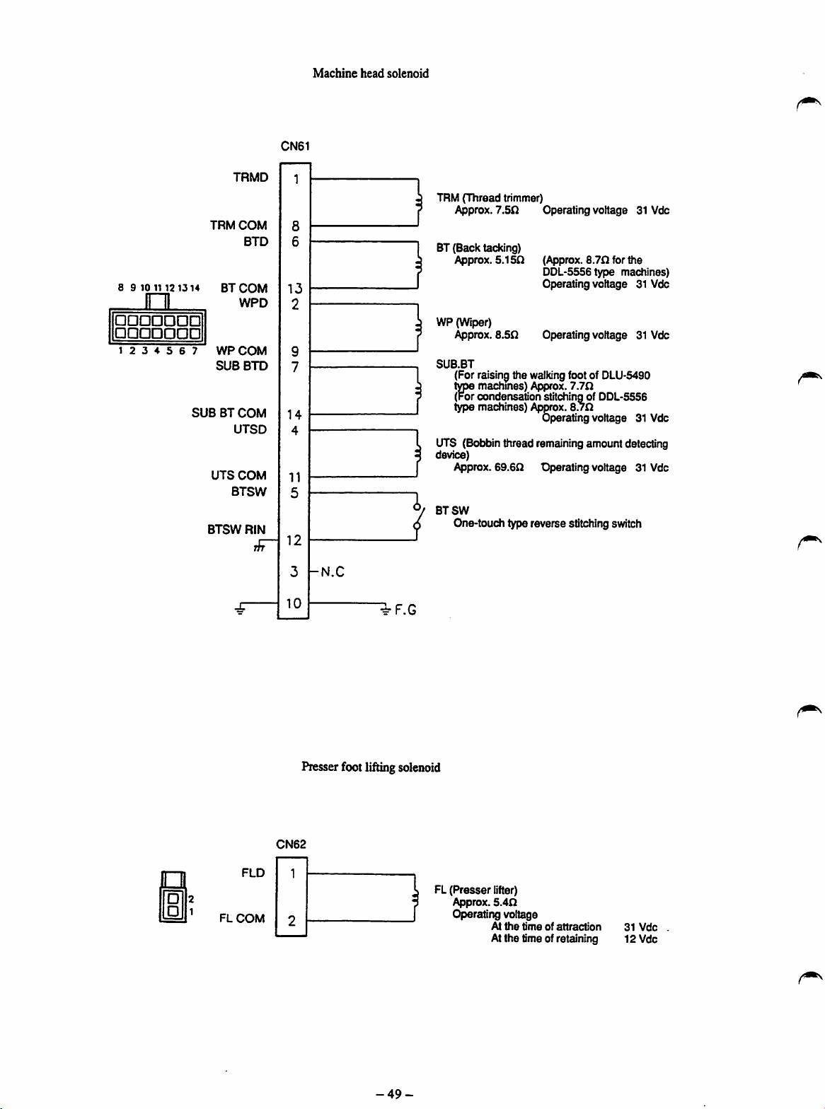
8 9 10 1112
1314
in
•••••••
•••••••
1 2 3 4 5 6 7
TRMD
TRM
COM
BTD
BT
COM
WPD
WPCOM
SUB
BTD
SUBBTCOM
UTSD
UTS
COM
BTSW
BTSW
RIN
r/n
CN61
13
2
14
4
11
5
12
Machine
head
solenoid
1
TRM(Thread trimmer)
Approx.
7.5n
Operating voltage 31 Vdc
BT(Back tacking)
Approx.
5.150
(Approx.
8.70
for
DDL-5556type machines)
the
Operating voltage 31 Vdc
WP (Wiper)
Approx.
8.50
SUB.BT
(For
raising
t^
machines)
(For condensation stitching of DDL-5556
type machines) Approx.
Operating voltage 31 Vdc
the
walking
footof
Af^irox.
7.70
8.70
Operating voltage 31 Vdc
DLU-5430
UTS (Bobbinthread remainingamount detecting
device)
Approx.
69.60
BTSW
Operating voltage 31 Vdc
One-touch type reverse stitchingswitch
3
-N.C
10
^F.G
Presserfoot liftingsolenoid
CN62
•
FLO
FLCOM
FL(Presser
Approx.
Operating voltage
M
Atthe time of retaining
lifter)
5.40
the
timeofattraction
31
Vdc
12
Vdc
-49-

SC-2
solenoid
valve
6 7 8 9
n
•••••
•••••
1 2 3 4 5
CN63
NBN3
COM
(Retains the
needle
thread)
10
NBN3D
(Retains
needle
thread)
NBN2
COM
(Draws
the
needle
thread)
NBN2D
(Draws
the
needle
thread)
NBN1
COM
(Attraction)
the
J77
J79
J78
Solenoid
(Retains
needle
Solenoid
(Draws
needle
Solenoid
valve
the
thread)
Operating voltage
valve
the
thread)
Operating voltage
valve
24Vdc
24Vdc
(Attraction)
NBN1D
(Attraction)
NBNV
+24V
Operating voltage
24Vdc
-50-
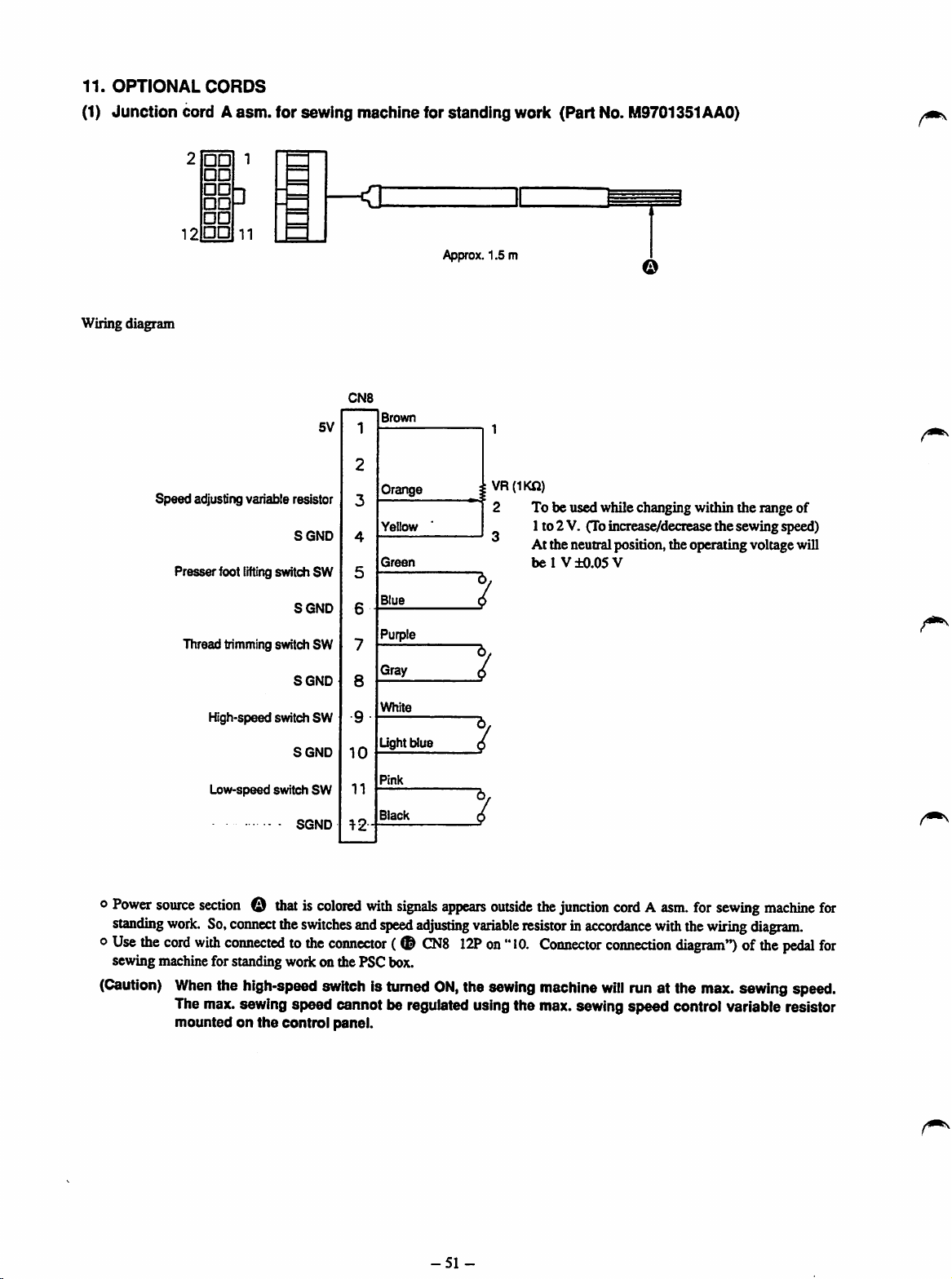
11.
OPTIONAL
(1)
Junction
Wiringdiagram
Speed
CORDS
cord A
12
Presserfoot
Thread trimmingswitch SW
asm.
for sewing
1
••
••
••
••
••
••
adjusting variable resistor
High-speed switch
Low-speed
3
11
lifting
-
-
SGND
switchSW
SGND
SGND
SGND
switch
SGND
SW
SW
5V
machine
^
CN8
Brown
1
2
Orange
3
Yellow
4
Green
5
Blue
6
Purple
7
Gray
8
White
9
Light blue
10
Pink
11
Black
12
for
standing
Approx. 1.5 m
work (Part No. M9701351AAO)
o
1VR(IKO)
2 To be used while changing within the range of
1to 2 V. (Toincreas^deciease the sewing speed)
At the neutral position, the operating voltage will
bel
V±0.05V
C
6/
(j
6.
6/
o
Power
source
sectionothatiscolored
standing
o
Use
sewing
(Caution)
woric
the
cord
machine
When
The
mountedonthe
So,
coimect
with
connectedtothe
forstanding
the
max.
the
switches
woric
high-speed
sewing speed cannot be regulatedusing the max.sewing speed control variable resistor
control
with
signals
and
speed
adjusting
connector(©CN8
onthePSCbox.
switchisturned
panel.
appears
12Pon"
ON,
-51
variable
the
sewing
-
outside
the
junction
resistorinaccordance
10.
Connector
machine
cordAasm.
with
connection
will
runat the
diagram**)ofthe
the
for
wiring
max.
sewing
machine
for
diagram,
pedal
for
sewingspeed.

(2)
Junction cordAasm.lorthe
a
a
a
a
Wiring diagram
CN11
Automatic counting
prohibition
switchSW
SGND
© SW
SGND
White
Black
Red
Blue
No.
ofpcs.
4
4
counter
When the switch is in theONstate, automatic counting
functionof the No. of pcs. counter is prohibited.
Every
on the No. of pcs. counter will increase.
(Part
No.
Approx. 1.5 m
timethis
switch
M9702351AAO)
isturnedON,the value
shown
o
Use
the
cord
with
connectedtothe
of
the
No.ofpcs.
(3)
Junctioncord Aasm.for24
Wiring diagram
o
Use
the
cord
the
PSC
box.
counteronthe
DC
with
connectedtothe
c
[=
24V
GND
connector
PSC
Vdc
CN64
( o
CNl
box.
(When
the
CP-230orCP-330isused
(Part
No.
M9703351AAO)
Approx.
yellow
connector(0CN642Pon
14Pon"
10.
1.5 m
Connector
Use
(UptolOOmA)
"10.
Connector
connection
with
the
the
cord
connection
diagram")
ofthe
machine)
with a solenoid, for
diagram")of24
external
reference.
switch
Vdc
on
-52-

12.
HOW
TO
(1) POL circuit
REPLACE
boardAAasm.
eflODCSn
(S4:2_J)
THE
CIRCUIT
[M8606351AAA]
a
BOARDS
1. Pushtwopoints Q on bothsides of the front coverto
open the front cover.
2. Remove pedal connector O "
(Caution) Be
suretoremove
while
holding
(Removing
the
cord
will
the
the
connector
cause
the
pedal
connector
while holding
imperfect
connector
section.
contact.)
How
dip
to fix
band
the
cable
c n n n n
Removing procedure of the
cable
dip
band
//
3.
Remove
procedureshown in the figureon the left to release the
pedalconnector.
cable
clip
bandOfollowing
the
removing
(Caution) The cable clip band is used repeatedly.
So, do not
or
the
like.
cut
itoffwith a pairof nippers
Attaching procedure •
of
thec^ledip
band
-53-
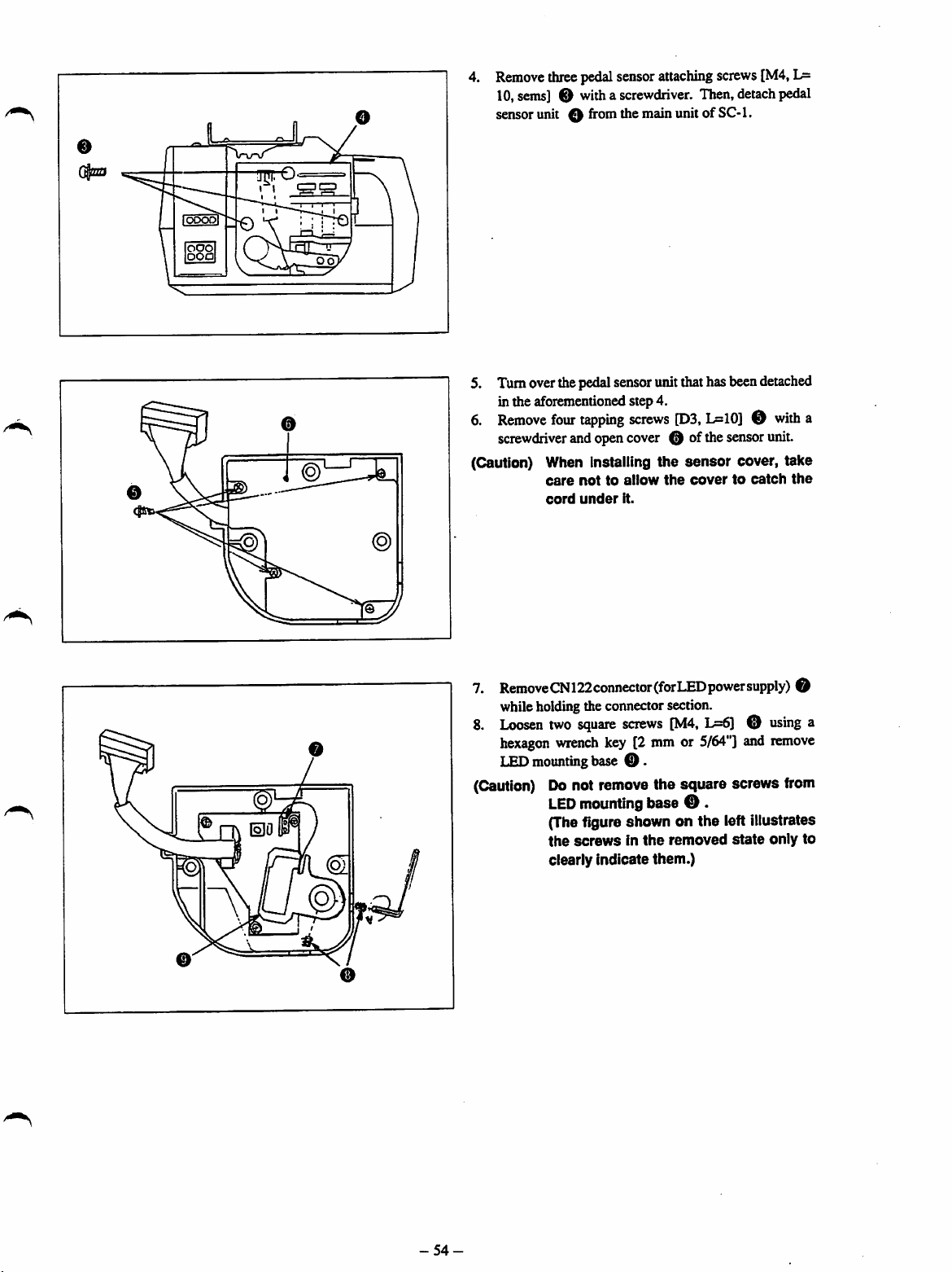
lOOOOl
©
Remove
10,sems] O witha screwdriver. Then, detach pedal
sensor
5. Turnoverthepedalsensorunitthat has beendetached
in the aforementioned step 4.
6.
Remove
screwdriver
(Caution) When Installing the
threepedalsensor
unit 0
from
four
tapping
andopencover 0 ofthesensorunit.
attaching
themainunitof
screws
[D3,
screws
SC-1.
D=10]0with
sensor
care
cord
nottoallow
under
the
covertocatch
It.
[M4,
L=
cover, take
the
a
7.
RemoveCN122connector(forLEDpowersupply)
while holding the connector section.
8.
Loosen
O
hexagon
T.Fn
mounting
two
wrench
square
screws
key [2 mm or
base
0.
[M4,
L=6)0using
5/64"]
and
O
a
remove
(Caution) Do not remove the square screws from
LED
mounting base 0 .
(Thefigure shown on the left illustrates
the
screwsinthe
clearly
indicate
removed
them.)
state
only
to
-54-
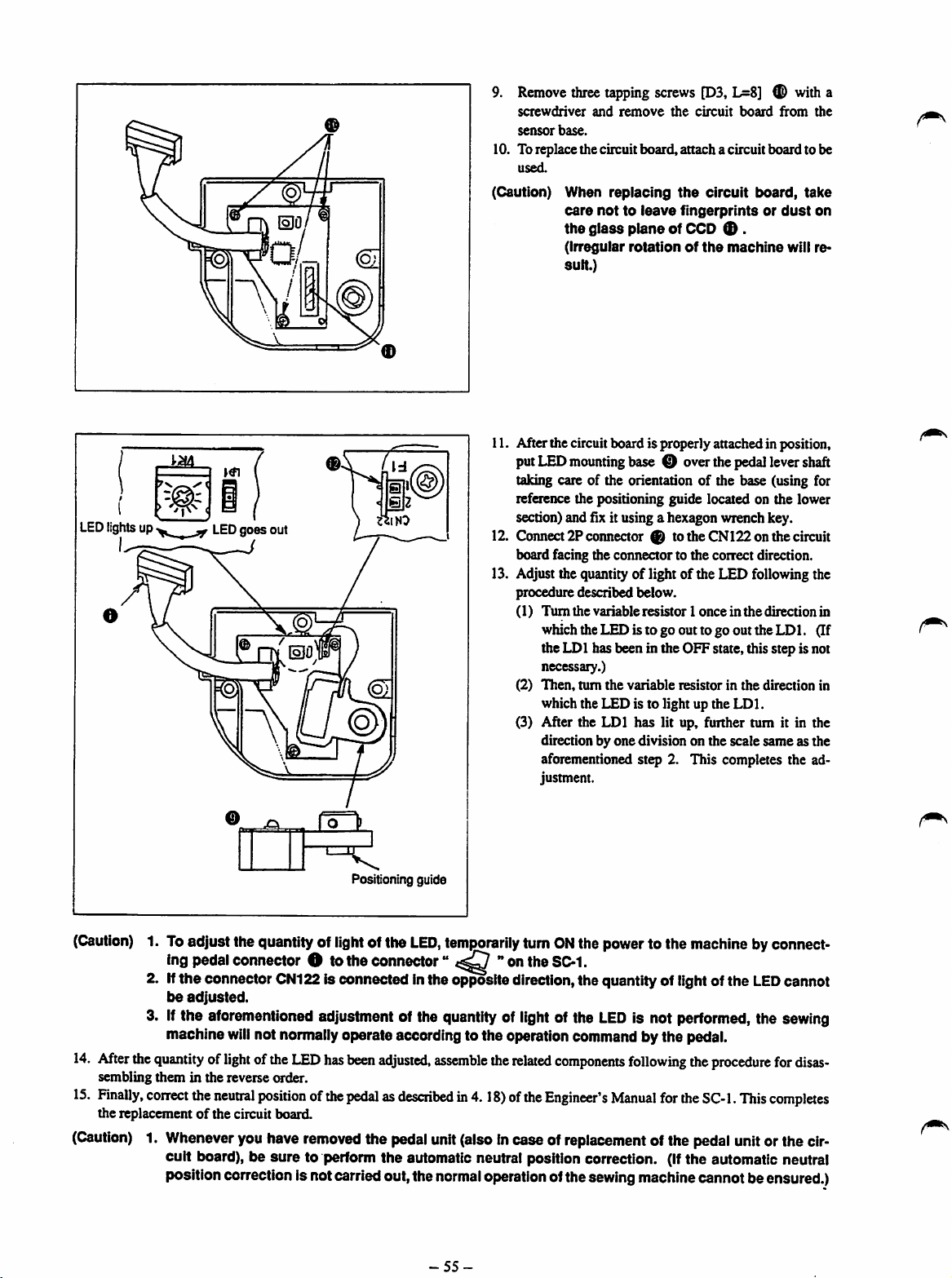
LEDlights up
V
LED
goes
out
9.
Remove
screwdriver
sensor
10. Toreplace the circuit board,attach a circuit board to be
used.
(Caution) When
11. After the circuitboard is properly attachedin position,
putLED
taking care of the orientation of the base (using for
reference the positioning guide located on the lower
section)and fix it using a hexagon wrench key.
12. Connect
board facing the connector to the correct direction.
13. Adjust the quantity of light of the LED following the
procedure described below.
(1)
(2)
(3) After the
three
tapping
and
base.
care
nottoleave
the
glass
(Irregular
suit.)
mounting
2?
connector ® tothe CN122on the circuit
Turn
the variable
which
the
LED
the
LDl
has been in the OFF state, this step is not
necessary.)
Then,
turn
the
which the LED is to light up the
LDl
direction by one division on the scale same as the
aforementionedstep 2. This completes the ad
justment.
screws [D3, L=8] w) with a
remove
replacing
the
circuit
board
the
circuit
fingerprintsordust
plane
of CCD ® .
rotationofthe
base O overthe
resistor1onceinthe
istogoouttogo
variable
resistorinthe
has lit up, further tum it in the
board,
machine
pedal
directionin
out
the
direction in
LDl.
from
the
take
on
will re*
levershaft
LDl.
(If
Positioning guide
(Caution)
1. Toadjust the quantity of
ing pedal connector O to
light
the
ofthe
LED,
connector"
temporarily
**
on the SC-1.
tumONthe
power
to the
2. Iftheconnector ONI22Is connected Inthe opposite direction,the quantity of lightof the
be
adjusted.
3.Ifthe aforementioned adjustmentof the quantity of
machine
14.
After
the
quantityoflight
sembling
15.
Finally,
the replacementofthe circuit board.
them
correct
(Caution)1.Whenever
will
in the reverse order.
the
neutral
youhave
not normallyoperate according to the operation commandby the pedal.
ofthe
LED
has
been
positionofthe
removed
adjusted,
pedalasdescribedin4.18)of
the
pedal
assemble
unit
(alsoincase of
the
light
related
the
of the
LED
components
Engineer's
replacement
is not performed, the
following
Manual
for
ofthe
cuit board), be sure to perform the automatic neutral position correction. (Ifthe automatic neutral
positioncorrectionis notcarriedout,the
normal
-55-
operationofthesewingmachinecannot beensured.)
machine
the
procedure
the
SC-1.
pedal
byconnect
LED
cannot
sewing
for
disas
This
completes
unitorthe cir

(2) Replacing
Push-
the
circuit
aUtuJCSn
fSC-
( )
boardsofthe
JS
re
5
(••••
o)
SC-1
>-Push
1.
Push
two
points
open the front cover.
2. 1)
Remove
2)
Unbind
3)
E)epre~ss
remove
O onboth
pedal
connector O " "•
cableclip band 0 .
the
front
cover.
sides
coverinthe
ofthe
front
cover
direction@and
(Caution) Be sure to detach the pedal connector
while holding
the
connectorsection.
to
ooooo
i
( )
Q^i>fflTOOOOOO
@
I
CDDDD
DJ
IS3II
O)
3. 1)
Remove
asm. 0 while holding the lock tab.
2)
Ronove
and
a
3)
Remove
plateusinga screwdriver.
transformer
connector
connector
screwdriver.
screw
panel
0 fromthe
input
panel
attaching
attaching
change-over
screws
screws
B 0
connector
cord A
A 0
using
installing
-56-

1) DrawconnectorpanelO towardyouuntilitcomes
off. Press lamp power connectors 0 , while
pinching the lack tab with your fingers, away from
you until it comes off. (Refer to ftgurc.)
a
Howtoremove
the
connector
S. 1)
Draw
outAC
input
connector
output
connectorO(4P)
2) Loosen screw ® which is used to retain the FG
using a screwdriver and remove the FG.
(Caution) 1.
The
FGs
have
the
order
as
timeofdelivery.
(S)
DRV.
2.
When
removing
to
drop
the
toothed
® (6?) and
from
connector
been
factory-installed
iliustrated
Motor Power supply
the
below
^
FG,
take
washer.
(p)
motor
installing
at
the
care
not
In
6. 1)
Turn
over
the
SC-1
and
the bottom coverusing a screwdriver.
(Caution) 1.
-57-
The
screws
been
off.
for
designedsothatthey
loosen
the
four
bottom
screws
cover
hardly
in
have
come
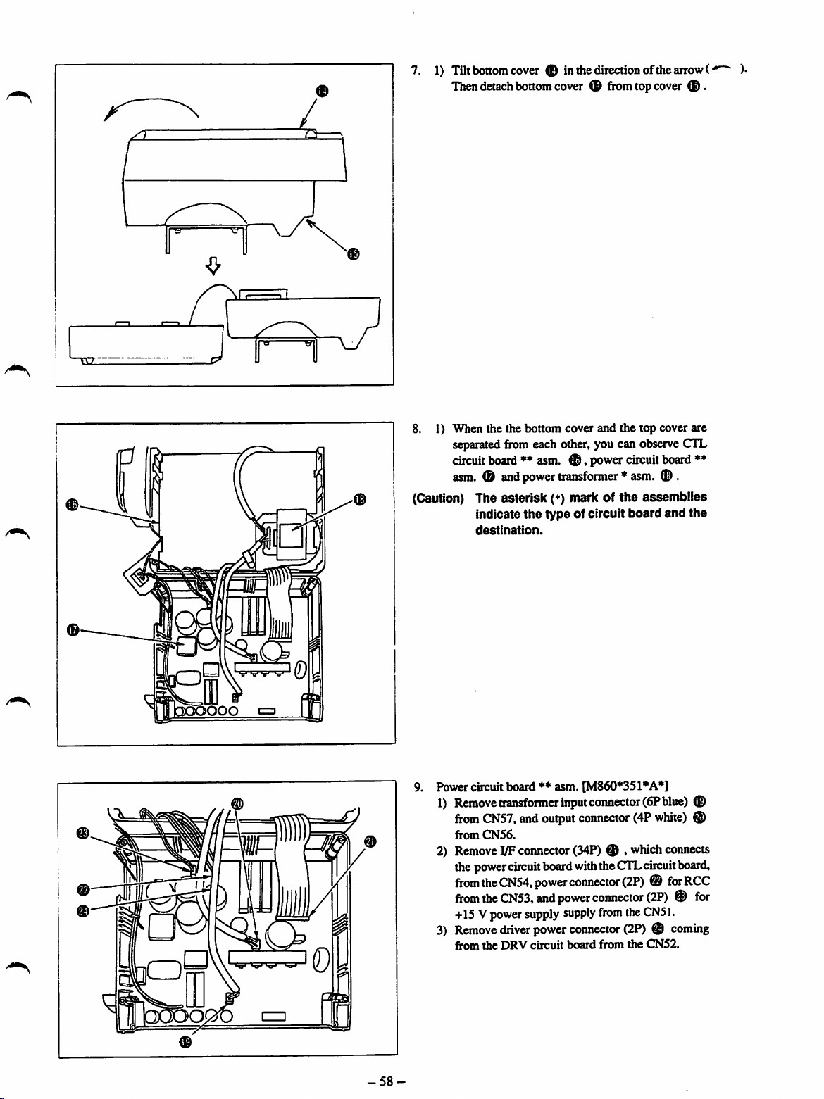
1) Tilt bottomcover (H inthe direction ofthearrow(•
Thendetachbottomcover fromtopcover ® .
8. 1) When the the bottom cover and the top cover are
separatedfrom each other, you can observeCTL
circuitboard** asm.®,powercircuitboard
asm.®and
(Caution) The asterisk (*) mark of
Indicate
destination.
power
transformer*asm.
the
type
of circuit
the
assemblies
board
(D.
and
*♦
the
Power circuit board♦♦asm. [M860*351*A*]
1)
Remove
from
from
•I
2) RemoveUFconnector(34P) ® , whichconnects
thepower
from
I
from
+15Vpower
3)
Remove
from
transformer
CN57,
CN56.
circuit
the
CN54,
the
CN53,
driver
the
DRV
input
and
output
connector
boardwiththeCTLcircuit
power
connector
and
power
supply
supply
power
connector
circuit
board
I
-58-
connector
(4P
(2P)®forRCC
connector
from
the
(2P) ®
from
the
(6?
blue)
white)
board,
(2P)®for
CN51.
coming
CN52.
®
®
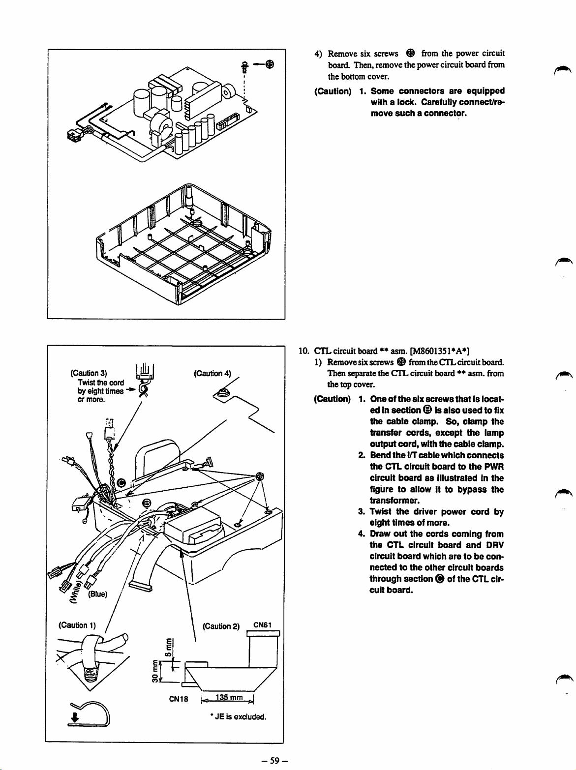
4)
Remove
six
screws
®
from
the
power
board. Then,remove the powercircuit board from
the
bottom
cover.
(Caution) 1.
Some
connectors
with
a lock. Carefully
move
suchaconnector.
are
equipped
connect/re
circuit
(Caution 3)
Twist
by eight times
or
more.
g
(Blue)
(Caution 1)
the
cord
m (Caution 4)
(Caution 2) CN61
I I
10.
CTL
circuit board*♦asm. [M8601351*A*]
1) Removesixscrews® fromtheCTLcircuitboard.
Then separate the
the top cover.
(Caution) 1.
2.
CTL
Oneofthe
edinsection
the
cable
transfer
output
cord,
Bend
the
the
CTL
circuit
circuit
board
circuit board ** asm. from
six
screws
thatislocat
is
also
usedtofix
clamp.
cords,
l/T(»ble
So,
except
vdth
the
which
boardtothe
as
illustrated
clamp
the
cable
connects
figuretoallow ittobypass
transformer.
3. Twist
4. Draw
the
eight
timesofmore.
out
the
the
CTL
circuit
circuit
board
nectedtothe
driver
cords
which
other
power
coming
board
aretobe
circuit
and
through section ® of the
cuit
board.
clamp.
in
cord
boards
CTL
the
lamp
PWR
the
the
by
from
DRV
con
cir
CN18
1^
135mm^
*JEis
excluded.
-59-

2} Raise the CTL circuit board as illustrated in the
figureontheleft. RemoveDRVcircuitboardsignal
connector®
connector ® from the CN120.
3)
Remove
coimect
board from the CN115. Then remove junction
coimector ® which is used to connect the CTL
circuit
CN116.
(Caution) 1. Spaclalattention
fromtheCN119,andpredriverpower
junction
the
board
connector®whichisused
CTL
circuit
board
with
with
theSWcircuit
must
nottoerroneously
CN120.
CN119
and
the
board
CN116.
LCD
circuit
from
be attached
connect
the
the
to
CK)po
//P
cunr
)2f
CMUb
Cti^
11. DRV circuit board*♦asm. [M8602351AA*]
1)
Remove
using a screwdriver.
screws®from
the
DRV
circuit
(Caution) 1. When assembling, be carefui to
attach spacer ® and sheet
together with
circuit
board.
the
screw, to
board
®,
the
-60-

12.
Power
transfoimer asm. [M8502351*AO]
1) Remove screws ® from the power transformer
withascrewdriver.
(Caution)
13. SW circuit board A* asm. [M8607351AA*]
1.
When
assembling,besuretoalign
transformer
positioning
® with projection ®
cover.
guide
on
the
hole
top
1) Removescrews ® fortheSWcircuitboard,using
0
a screwdriver, from display setting device * asm.
0 .
Then,
removeSWcircuit
board*
asm.
®.
When
assembling
the
circuit
boards
after
the
replacement,
follow
14.
LCD
unit A asm. [M8503351AAO]
1) Remove screw ® from the LCD unit with a
screwdriver.
2) Openthethree circuit holders in the directionof the
arrow ( m ), then remove LCD unit A asm. 0 .
(Caution) 1.
the
inx)cedure
Carefully
board
the
break
2. Be
tighten
cult
they
for
disassembling
holder
arrow
ifyou
careful
the
board
are
tapping
opening
in
the
(«>),
since
open
them
nottoexcessively
screws
them
and
LCD
screws.
inthe
for
reverse
the
circuit
direction
they
roughly.
the
SW cir>
unit,
of
may
since
order.
-61
-
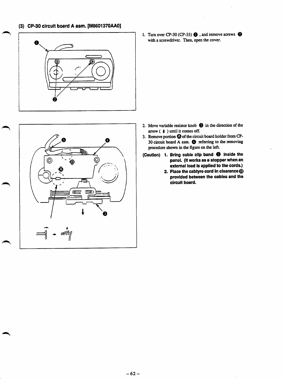
(3) CP-30 circuit
©
boardAasm.
0
[M8601370AA0]
1.
Turn
over
CP-30
(CP-33)
with a screwdriver. Then, open the cover.
2. Move variable resistor knob 0 in the direction of the
anow(
3.
Remove
30circuit board A asm. O referring to the removing
I ) until it comes off.
portion
procedure
shownin thefigureonthe left.
0 ofthe
(Caution)1.Bring
panel. (Itworksasa
external load Is appliedtothe
2. Place the cabtyre cord Inclearance©
provided between
circuit
O , andremove
circuit
board
holder
screws
from
O
CP-
cable clip band 0 insidethe
stopper
the
board.
cables
when an
cords.)
and the
HI - H
-62-
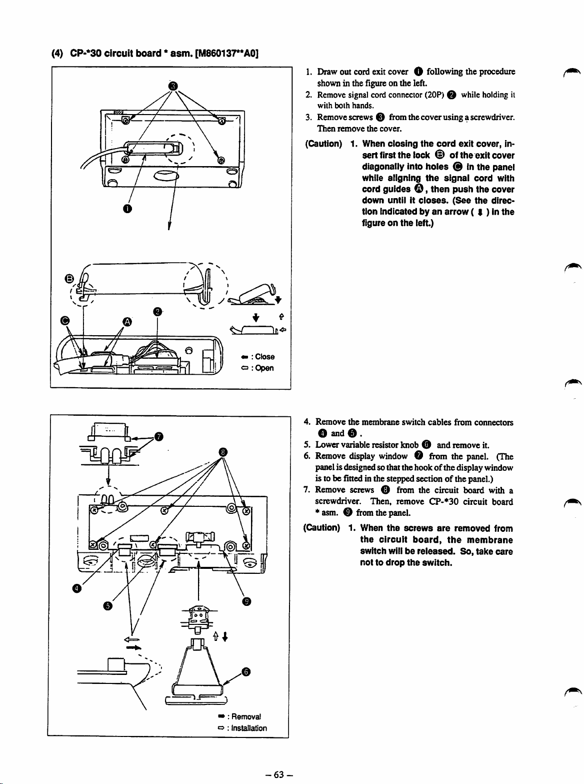
(4) CP-*30
circuit
board*asm.
O
[M86013r*A0]
1.
Draw
outcordexitcover O following the
shown in the figure on the left.
2.
Remove
signal
cord
connector
with
both
hands.
(20P)Owhile
procedure
holding
3. Removescrews0 fromthecoverusinga screwdriver.
Then
remove
the
cover.
(Caution) 1.
When
sert
closing
first
the
lock tD of
the
cord
exit
the
cover,
in
exit cover
diagonallyinto holes 0 in the panel
while
aligning
the
signal
cord
with
cordguidesO,then push the cover
down
until it
tion
indicatedbyan
figureonthe
closes.
left.)
(See
arrow
the
direc
(I)Inthe
it
i
raws?
(OH
^ i
« :
o
Close
:Open
4.
Remove
the
membrane
switch
cables
from
connectors
O and 0 .
5. Lower variableresistorknob 0 and remove it.
6.
Remove
display
window0from
the
panel.
(The
panelisdesignedso that the hook of the displaywindow
is to be fitted in the steppedsection of the panel.)
7. Remove screws 0 from the circuit board with a
screwdriver.
*
asm.0from
(Caution) 1, When
Then,
the
panel.
the
the
circuit
switch
willbereleased.
nottodrop
remove
screws
board,
the
CP-»30
are
switch.
circuit
removed
the
So,
board
from
membrane
take
care
•»:
Removal
o ;
Installation
-63-

13.
CIRCUIT
1) CTL
CTL
circuit
circuit
BOARD
boardAAasm.
boardABasm.
MOUNTING
DIAGRAM
[M8601351AAA]: Excluding
[M8601351AAB]:
JE
JE
lUsDsDsDiU
58B888IiE
B83B9S
•pcmED
Rtt
I
im
00
£3
£21
H P
Bt
an
a:
_
I
,"7:
5'no".
8 :
-iOl jO.iD
f
S!
LL • -•
BS9B
SBBi
rnuiIID
1
-64-

2)
Power
Power
Power
Power
Power
Power
circuit
circuit
circuit
circuit
circuit
circuit
board
board
board
board
board
board
B *
C *
E *
F *
G *
H *
[M8604351BA*] : General export 03 200 to 240 V
asm.
asm.
[M86D5351CA*] :
asm.
[M8604351EA*] :JA03
asm.
[M8605351 FA'] :JA0I
asm.
[M8605351GA*] :JA0I
asm.
[M86053S1HA*] :
General
General
export
01 200to240 V
200
to 240 V
100to120
200
V
to 240 V
export0I100to120
[Note]
The
asterisk
represents the
(*)
type ofsewing
V
machine
A:SC-1
B;S02
controller.
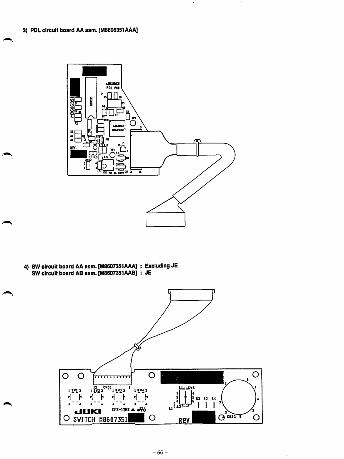
3) PDLcircuit board AAasm.
a
oof=^
• TLITU
wjn
0
[M8606351AAA]
POL
pa
I*«
!=r-—I
VqJ
«« ••70W®' ' *
4)
SW
circuitboardAAasm.
SWcircuit board ABasm.
I SWI 2 1 SW2 2 * I SW3 2 I
•I
3 *
^
O
SWITCH
!>
[M8607351AAA]:Excluding
[M8607351AAB]
i
11111111111
12
CM3I
•!
t"
3~''«
HCl
S""*
CnK-128X•cSUl
: JE
1
S*<
3
H8607351^H
JE
2
O
LtriSVG
CIIS2.
S
-66-

5) DRV
DRV
DRV
circuit
circuit
circuit
boardAAasm.
I
boardABasm.
boardACasm.
[M8602351AAA] : General
[M8602351AABi;JE
[M8602351AAcj:JA
DRV
PCB
-n
O
export
6) CP-30 circuit
lOQOoooaoooL
board
Aasm.
[M8601370AA01
^
l^SOOO-r
jopooDODOQan
GCt1!(~44XABc E
REV,


n =
• =
• =
IqcsI
laal
laal
Isal
laal
•

[M8601373AA0]
asm.
A
board
J
4L
rr
:•
"•
=
i =
1 o
•Eg
I
ci
^"eS
cPU
Z -
'^irrPs
I4« M
P"'s
n y
1=^.-=
9) CP-330 circuit
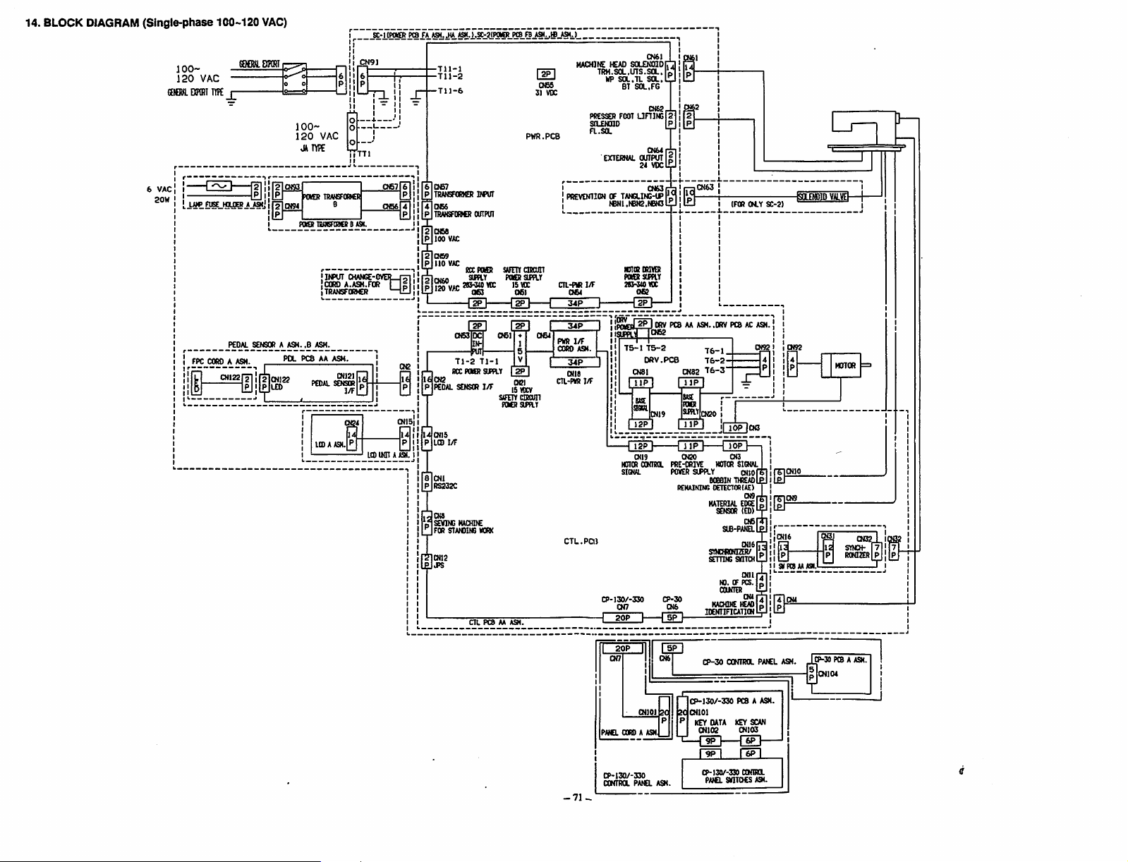
14. BLOCK DIAGRAM
(Single-phase
100-
120
VAC
CEIQVl
DIFCRIirFe
6 VAC
20W
{11
100-120
COeULDKHI
JL
CNI22
y?|!
liljlNLO)
VAC)
Jji!
PO-
100120
JUTYPE
POKER
Fast
PCS
PEDAL SENSOR
VAC
TTTl
TRMEFOKR
nflEFoace
BASK.
•ItfiUT
CHANGE'
CCRO
A.ASH.FOft
TRAN5F0R»CR
AA ASM.
CN12I
1/F
ICDAASM.
P|
SC-KPOBfMBFA
n®|
CN2
(N15i
LtD
(torAASH.
ASH.
JA ASH.).a>2iPOIOLre8.FBJi91i,ffiJS(J_
-711-1
-711-2
r^CN57
^TRANSFORMER
^066
[NTRAKSFIRER
[^068
[m
[^069
IpIiio
V
fajotto
P 120 VAC
rL
ieCN2
pIpeoal
Mcnib
iP
LCD
I
8 CNl
|P
RS232C
JQH
1SEVING
Jfor
|CN12
|J>S
too
VAC
vac
CN53
71-2
RCC
SENSCR
1/F
STATOING
INPUT
OUIPUI
RCCTWER
jiSoV
{in
71-1
POKER
SUPPLY
I/F
HACHDC
KRK
CTL PCS AA ASH.
sAFEncnaflT
061
StfETYtaRCUn
POCRStmr
PWR.PCB
POSSSUEaY
I5WC
061
[1]
iM]
OS]
ISVDCV
MACHINE
TRH.SOL,LnS.SOL.P,a
065
31 VDC
HP
PRESSER
StLEKHO
a.sa
EXTERNAL
! CN63r
PREVENTIONOFTANGLINS-UPf
064
PNR
I/F
COfiO
A9I.
|_^
34P
I
CNI8
CTL-PKHl/F
C7L.Paj
CP-130/-330
—I 20P I
CN51
SOLENOIDO
SOL.LJ
SOL.FG
CN62,
UHING
jPI
CNGAj-i
OUTPUT
24
VDCi^
I
2
|
HEAD
Sa.U
FOOT
BT
TeNl.ieN2.(6N3l
lOICRRIVER
POKER
stmr
ISHMIDC
062
2M0RV
amjTTosR
75-1
WTOR
SIGNAL
CN7
PCSAAASM..DRV
75-2
ORV.PCe
CN8I
USE
sm
CN19
0(19 OBO CN3
OONTRX
PRE-ORIVE
POVER
REMAINING
CP-30
0(6
{"sFl-
OK2
IF
CN63
76-1.
76-2-
CN82
76-3"
TT^
ta
FDKS
SUPIY
,CN20
SIPPLY
eceaiN
MATERIAL
StNEHDNnER/
SEmNG
MACHINE
lOENIinCATIONl
(FOR CM.Y
PCSACASM.
I
lOP
MOTOR
SIGNAL
(MlorSl
THiEAol
OETEa(K(A£)
EDGE
SENSOR
(ED)'
S(fi-PA(£LL
CNlBi;
SKITCHl
CNlll
NO. OF PCS.
OWTER
ICMI
oe,
oer
OUl
CN3
4
P
SC-2)
! !
-KOLEMDID
4
!
"1
I
1
I
I
SKFCSAAASI.
sr
VALVEh
H(nCIR
CN32
SYNCH-
r?!
RONISR P
I !
-71-
20P
PA)B.
CORDAASM
CP-130/-330
CONTRa
oiT
f—1
20 20
PANEL ASM.
5P
p
CP-30
-L.
CP-130/-330
QMOl
P
KEY
CN102 CHI03
CP-l30/-3»
COKTRa PAICL ASH
PCS A ASM.
DATA
KEY
9P1
1^
rgpi
PAICLSHITOCS
ONSa.
SCAN
A».
tP-30
4.
PCSA ASH.
Jo
CNKM
J

15.
BLOCK
DIAGRAM
(Single-phase 200-240
200-
240
VAC
6
VAC
Lii*
FPC
aiRO_A
ASH.
OI133
VAC)
i
r^oiM
IRMEK
CN133
LEO
^OEH TRANSFOMIi
nWCFOaa
P(KR
POKR
IStffiFORNEB0itSI.U
POL
PCBAAASH.
C
CilSN.(SI6UL
IRMSFQRWR
0-
INPUT
'CORO
A.ASK.EOR
jTRANSFORKER
_ASM.
CNI3I
PEDAL SENSOR
I/F
LCD
A ASH.
OUNCE
scrLtEf®
EVCBT
TTTO
Q<2
TIKI
£®
2
P
2
P 330
IPICKAO
P
MO^VAT
PI340
OC
1£|CN3
pIpeoal sensor I/F
Mats
pIlcd
6 CNI
P
RS333C
]CN8
1SEV1IC
I
FOR
)CN13
IJPS
J1«!LL§F::2KS®L^©
Tll-l
Tn-4
Til-6
068
300
VAC
069
VAC
ROC
PCKR
®>3(0
VDCISVDC
VAC
OK
-OEl—[lEI—C
[gp]
063
OC
INPUT
71-2
71-1
ROC
POKR StFPLY
1/F
MACHIIE
STAMllNG
MQRX
aL
PCS AA
ASH..aL
SAFETT
FOERSUPdY
C»1
CNBI
rap]
oei
15
VDC
SAFETY
dROUn
POeRSUYlT
PCS AS ASH.
MACHINE
LED
066
31 VDC
PWR.PC8
CTRCUIT
TRH.SOL.UTS.SOL.
PRESSED
SOLENOID
a.SOL
I CNS3r
I
PREVENTIONOFTANGLING-UP
CTL-PVR
1/F
CN54
34P
I
PHR
1/F
CORD ASM.
CN18
CTL-PH81/F
C7L.PCB
CP-130/-330
CN6I
>CAO
SOLENOIOr,.
HP
Sa.U
SOL.
BT
SOL.FG
063
FOOT
LTniNGlal
EXTERNAL
CNUr,.
OUTPUT
34
VDCr
reNi.terc.NOGlJ^
NOIORDRIfDt
POORSUflT
3«3-340VDC
063
2PJ
DRV
aFpyn063
75-1
76-2
ORV.PCB
CN81
ttSE
SOPL
CK19
CNI9
H01CR
CCNRX
Slow.
CK7
20P
D—mo
'
|P|
§
]CN63
L •
PCSAAASH..OfiV
7^,
76-2-
CN83
76-3'
USE
foa
smr
jQgO
Glpj
•fTTpi—rrppi—
000
PRE-ORIVE
POVER
SIPPLY
eoeeiN
rekainim:
MATERIAL
SKNOiaaiER/
srrnNs
CP-30
06
IDENTIFICATION
IFOR
PCBASASN.
I
!n^
00
MOTOR
thread
oetector(ae)
SENSOR
SIB-PANEL
svitch
NO. OF PCS.
COKTER
MACHINE
SIOUL
auo
019
EDGE
(ED
lEAO
OLY SC-3)
CN3
l;
-fiCLEWDID
VALVD-
MOTOR
STNCH-
R0NI2ER
»PC8AAASI..SVF(BA8A9<
I !
-72-
PAKL
OORD
CP-130/-330
CCNTRa
01101 3C
A ASM
PANa
ASN.
CP-30
CP-130/-330
CNlOl
KEY
DATA
CN^
DP
ripi
CP-I30/-J
PAtCL a
CONTROL
PCB A ASM.
KEY SCAN
SOQNTRCL
ITOCS
PAASL ASH.
A91.
CP-30 PCS A
CN104
ASM.

16.
BLOCK DIAGRAM
(3-phase
200-240
VAC)
£-l(P(KI>
PCSU A9<.,eA JQM.).SC-2(FaKS PCSE8 A9I..EB ASH.)
200-
240
VAC
=^=iii
LAJP
RS.HDLDEJJJWJ i
CORD_A
SK]%E)ratI
PEDAL
ASH.
CNI22
200240
OAIYPE
POKERTRAKSFOnSS
POKER
SENSORAASK^.B
VAC
C
IIUNSFORICR
INPUT CHANGE-0
CORD A.ASH.FOR
TRANSFORHER
ASH.
**
*SM.
CNI2)
PEDAL SENSOR
LCDAASM.K
1/F
C ASK.
LCD
§
(NnAASK.
Tll-I
Tl)-2
Tll-4
T1J-6
6 CN57
PITRANSFORKER
4|CN56
P
TRMISFORNER
2
068
P 200 VAC
CI69
2
p|220
PICHM)
P
aO^VAC
P
PEDAL
I'UaiS
P LCD
I
8 CNl
P
RS232C
cm
p.SEVING
^
FOR
OUTPUT
VAC
RCC
I2PI
RCC
POKER
SENSOR
I/F
HACHIfC
STAAOING
CTL PCS AA ASH.
INPUT
POKR
SAFETY
Pora
™15VK
SUPPLY
I/F
SAFnYdRom
POCR SU>PLT
WKK
[^]
DC)
IS MX
[1E3
oes
31 VDC
PWR.PCB
CIRCUIT
SUPPLY
HACHINE )CAO
TRH.SOL.UTS.SOL.io,
HP
SOL.TL
BT
PtXSSCR
FOOT
SCLENOID
FL.SOL
EXTERNAL
PREVENTIONOFTANGLINS-UP
CIL-PKR
1
PKR
CORD
cms
CIL-PKR
CTL.PCB
34P
I/F
ASH.
1/F
1/F
CP-I30/-330
leNi.reTC.NBNjlf
NOTORmiVER
POKDf
283-3(0
gjpptM
T5-1
HOTCR
SIBUL
CN7
SOLENOIDn
SOL.lU
SOL.FG
Cn6Z
UniNS|2
IP
CN64,.,
OUTPUT
i
2i
VOC'P
CN63,,
'
SUPPLY
VK
i^ORV
PCSAAASH..ORV
1062
T5-2
DftV.PC®
CNSI
IIP
I IHPI
CN19 CN20 CN3
ONTea
CW82
PRE-DRIVE
POKER
SUPPLY
REKAININS
T6-2
T6-3
CK20 t
)«nCIR
BOBBIN
OETECTORIAEI
MATERIAL
SENSOR
SLB-PAIEL
SnOfiOOZR/
SETTIMTSKnCH
10.
COKIER
KIOONE
IDENTIFICAIION
IFOR OM-Y
PCSACASH.
JOP
CH3
lOP
SIGNAL
q(io
THiEAD
019
EDGE
(ED)
CN5
0(16
oai
OF PCS.
CN4
ICAO"
SC-2)
I SKFCSAAAa
ISaEMOlD
VALVtl
MOTOR
0132
SYNCH-
RONIZER
|7
P
-73-
PAtCL
CP-I30/-330
CONTRa
OGRDAASH
PANEL
ASN.
CP-30
CCNTfia
CP-130/-330
CNlOl
KEY
DATA
CN102
CP-I30/-330 COHIRa
PAICLSVITOCS A9<.
PAfCL ASH.
PCS A ASH.
KEYSCAN
CP-30 PCS A ASH.
CN104

To order or for further information,
pieaae
contact:
•JUKI
JUKI
CORPORATION
BUSINESS
1-23-3
SHINJUKU-KU.
PHONE:
FAX:
TELEX
OFRCC
KABUKI-CHO
03(3203)8^.
:J22967.
TOKYO
03(3205)1188.1189.1190
03(3206)9131
232-2301
160.
JARIKN
 Loading...