

Page 1
•JUKI
SWING-TYPE
SEWING
MACHINES
SHIRRING
MO-2400N
ATTACHMENTS
AND
S057-8058
8097.8098
IN8TRUCTI0N
-2500N
SERIES
MANUAL
No.05
BES05730B0A
Page 2
These shirring attachments, S057, S058, S097 and S098 are designed for use with JUKI overedgers and
safety stitchers MO-2400N and -2500N series.
Please read this manual carefully before using these units in order to get the most
outofit and to enjoy
using it for a long time.
1.
MODELS
Swing-type Shirring Attachments for MO-2400N and -2500N series
5057 : Swing-type Shirring Attachment (pedal-operated) for safety stitchers
5097 : Swing-type Shirring Attachment (manually-operated) for safety stitchers
5058 : Swing-type Shirring Attachment (pedal-operated) for overedgers
5098 : Swing-type Shirring Ajtachment (manually-operated) for overedgers
2.
APPLICABLE
SEWING
MACHINES
—--.-^^Attachment
Series
MO-2400N
MO-2500N
3.
SPECIFICATION
Application
~~~~~—
MO-2416N
BD4,
DD4, DD6,
MO-2443N
MO-2516N
BD4, DD4, DD6, DE4,
MO-2543N
To provide shirring partially or continuously on light-weight articles
S057,
DBD6
DBD6
DE4,
S097
DF6,
DF6,
such as ribbed knit, light-weight knit and broadcloth garments.
Sewing speed
Differential
feed
ratio
5,000 through 5,500 s.p.m.
Overedger
-1:3,
Safety stitcher
materials)
Liftofpresser foot
4.
REPLACEMENT
The
gauge
set of a
sewing
Overedger - 5
GAUGE
SETS
mm.
Safety stitcher - 6.5 mm
machine must be changed when a shirring attachment S057, S058, S097 or
S098 isinstalledto the machine Select the most suitable
DH6,
FF6,
RH6
MO-2412N-DF6
MO-2414N-BD6,
MO-2504N-0D6,
MO-2404N-0D6,
DH6,
FF6,
RH6
MO-2512N-DF6
MO-2514N.BD6,
-1:3
gauge
set out of those listed below.
(Adjustable for each type
S058,S098
0F6,
BE6
0F6,
BE6
0H6
0H6
of
(1)
When
installing
•—-..^^Gauge
Nameof parT
Presser
foot
(asm)
Main feed dog
Differential feed dog
Needle
guard
Throat
plate
* Shirring presser ,
plate
Screwofneedle
The
shirring presser plate is replaced only
size
guard
S057
BD4
11879558
11883709
11885704
B4120816
DOBA
Standard
-
and
S097tosafety
DD4
11879657
11883808
11885704
B4120816
DOBA
Standard
-
DD6
11879657 11879657
11883907
11885803
B4120816
DOBA
Standard
-
for
RH6.
stitchers
DE4
11883808
11885704
B4120816
DOBA
R4508H0
EDOO
-
(MO-2416N,
DF6
11983657
11884806
11885902
B4120816
FOCA
R4608H0
FDOO
-
SS-7060610-SP
2516N,
FF6
11880457
11884103 11884103
11885902
B4120816
FOCA
R4612H0
FBOO
2443N,
RH6
11880853
11885902
B4120816
ROA
R4618H0
HBOO
-
♦MAS
0510800A
2543N);
DH6
11973963
11884806 11884806
11885902
R4120816
FOCA
R4608H0
HDOO
-
DBD6
11975950
11885902
B4120816
FOCA
R4608H0
DEOl
-
Page 3
(2)
When
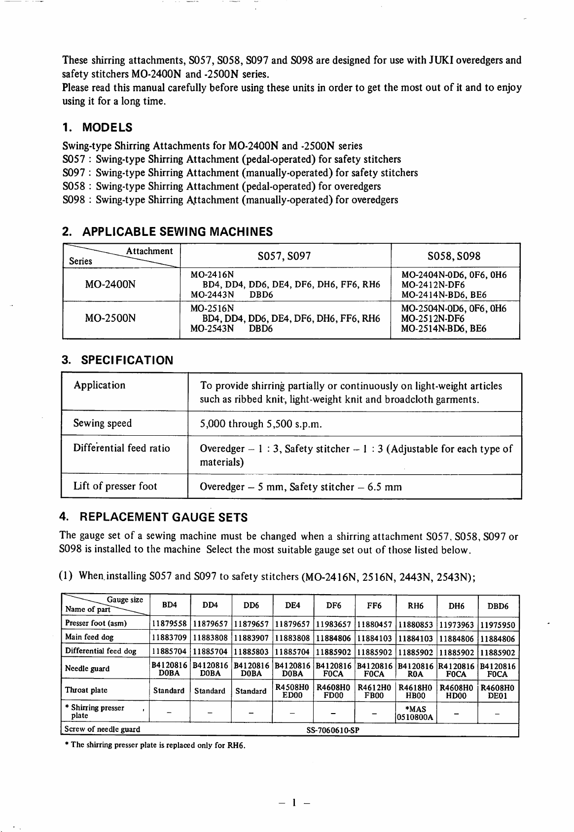
installing S058 and S098 to overedgers (MO-2404N, 2412N, 2414N, 2504N, 2512N, 2514N);
Gauge size
Name
ofparts \
Presser
foot
Main feed dog
Differential
dog
Throat
plate
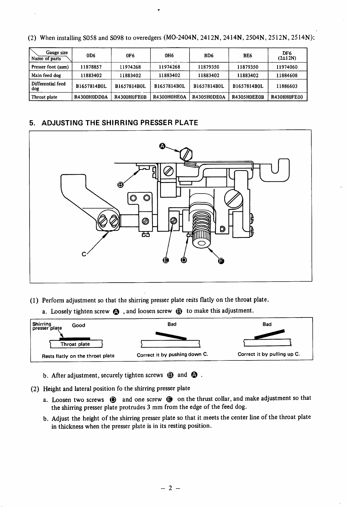
5.
ADJUSTING
(asm)
feed
0D6
11878857
11883402
B1657814B0L
R4300H0DD0A
THE
0F6
11974268
11883402
B1657814B0L
R430OHOFEOB
SHIRRING
11974268
11883402
B1657814B0L
R4300H0HE0A
PRESSER
0H6
PLATE
BD6
11879350
11883402
B1657814B0L
R4305H0DE0A
5
BE6
11879350
11883402
B1657814B0L
R4305H0EE0B
DF6
(2A12N)
11974060
11884608
11886603
R4308H0FE00
lT
(1)
Perform
adjustment
sothat the
shirring
presser
plate
rests
flatly
onthe throat
a. Loosely tighten screw , and loosenscrew (s) to makethis adjustment.
Shirring
presser
Rests
b.
(2)
Height
a.
plate
After
Loosen
the shirring
Adjust
in thickness when
Qood
Throat
plate
flatlyonthe
adjustment,
throat
plate
securely
[ 1
Correct it by pushing
tighten
screws
Bad
and lateral positionfo the shirring presser plate
two
screws
presser
the
heightofthe
(D
and
one
screw
© onthe
plate protrudes 3 mmfrom the
shirring
the
presser plate is in its resting position.
presser
platesothatitmeets
and
down
C.
© .
thrust
edge
of the feed dog.
collar,
the
Correctitby
and
make
center
plate,
Bad
pullingupC.
adjustmentsothat
lineofthe
throat
plate
- 2 -
Page 4

Shirring
presser
3
mm
plate
(3-ro.wfeed dog)
3
mm
(2-ro\A/
Shirring
presser
feed dog)
plate
Throat
Contact
Shirring
plate
presser
without
plate
gap
®
(3) Longitudinal positioning of the shirring presser plate
When
the differential feed dog has completed its
feeding
motion, the top end of the shirring plate
must be about three teeth behind (overedger) or 1 or 2 teeth behind (safety stitcher)ofthe
the differential feed dog as illustrated below.This is the adjustment for the standard pitch shirring.
By changing the longitudinal position of the shirring presser plate, different shirring pitch is
obtained. Adjust the longitudinal position by the typeoffabrics.
3-teeth (overedger)
When
the stitch lengthis
2.2
mm
and
the
differential
feed ratio is
maximum.
Main
feed
dog
Differential
feed
dog
top
of
(4)
Pressure
a.
6.
INSTALLING
of the
The
shirring
standard
presser
pressure
the presser plate is 1.5
THE
SHIRRING
applied
Kg.
Fix the shirring wire (asm) to the
plate
by the
Adjust
top
cover by the two thread tension posts.
the
pressure
WIRE
shirring
(ASM)
presser
plate to the
by knob (9 for the type of
Shirring
wire
(asm)
Thread
workpiece
tension
posts
at the top end of
fabrics.
- 3 -
Page 5

7.
ADJUSTING
THE
LIFTING
AMOUNT
(8057,
3058)
a. Loosen screw
standard
8.
ADJUSTING
lift
<D
and move up or down to adjust the liftofthe shirring presser plate. The
is 3
mm.
Presser
foot
Throat
V=2=^
!5 mm
plate
3
T7"
mm
rc
D
0
THE
MANUAL
LEVER
(S097,
S098)
Adjust
the
protrusion
of the
whenthe manual leverhas
9. CUTTING
When
stalled
S057
toamachine
THE
MACHINE TABLE (Fully-sunken
or
S058
is
in
head
set up on a fully-sunken
type table, modify the
mounting opening in the
table as shown in
right.
the
figure
manual
raised
leverbymeans
of its
locknut
so that
clearanceAis
the shirring presserplate 3 mm abovethe throat plate surface.
iyw"''Xl
3^^Noclearance
^ at point A
•>T
Manual
lever
Manual
Point
lever
A
locknut
type
table)
eliminated
10 10
- 4 -
Page 6

10.
INSTALLING
THE
KNEE
LIFTER
(1) Installthe leverinstalling basemounting plate asillustrated below.
Table
Bolt
Setscrew
Frame
Lever
mounting
base
support
plate
O O
Tl
plate
(Note)
For
table-top
Fix
the
lever
platebythe
For
the
table-top
replace
support
with
the
the
plate
unit.
base
bolt
bolt
and
with
bolt
type
mounting
setscrew.
type
table,
the
supplied
Setscrew
For
fully-sunken
Fix
the
lever
platebythe
base
two
type
mounting
setscrews.
Page 7

(2) Attach the knee lifter to the lever base mounting plate according to the following procedures.
a. Attach lever base O to
the
frame support plate using screws @ and washers o
b. Insert shaft © into lever O , and fasten it by screw © .
c. Insert one endofconnecting rod ® into the holeofthe differential feed contort lever from
inside, and insert
the
other
end into the holeoflever © . Then lock the connecting rod to
the
lever with split pin © .
d. Attach the knee press plate © to rod © and tighten screw © at a convenient height.
Side
viewofA
- 6 -
Page 8

To
order
or for further information,
please
contact;
•JUKI
JUKI
CORPORATION
HEAD
OFFICE
8-2-1
KOKURYO-CHO.
CHOFU-CITY. TOKYO 182. JAPAN
BUSINESS
1-23-3
SHINJUKU-KU. TOKYO 160.
PHONE : 03(3205)1188. 1189. 1190
FAX:03(3203)8260. (3205)9131
TELEX;
OFFICE
KABUKI-CHO
J22967,
232-2301
JAPAN
Please do not hesitate to contact our distributors or agents inyourarea for
*The
description covered in this instruction manual is subject to
commodity
without
notice.
further
information
change
for improvement of
1992.12PrintedinJapan
when
necessary.
the
 Loading...