

Page 1

ENGLISH
Lu-2220N-7
INStructIoN MaNuaL
i
Page 2

CONTENTS
1. SPECIFICATIONS .................................................................................................................... 1
2. INSTALLATION ........................................................................................................................ 1
(1) Attaching the hinge seats and support rubber of the machine head .............................................. 1
(2) Attaching the oil pan ............................................................................................................................1
3. INSTALLING THE WASTE OIL CONTAINER ......................................................................... 2
4. ADJUSTING THE BELT TENSION .......................................................................................... 2
5. INSTALLING THE SYNCHRONIZER SUPPORT ROD ........................................................... 2
6. ATTACHING THE BELT COVER ............................................................................................. 3
7. INSTALLING THE KNEE SWITCH .......................................................................................... 3
8. INSTALLING THE AIR DRIVE UNIT ........................................................................................ 4
(1) Installing the air control unit ............................................................................................................... 4
(2) Connecting the air hose ....................................................................................................................... 5
(3) Adjusting the air pressure ...................................................................................................................6
9. INSTALLING THE THREAD STAND ....................................................................................... 7
10. LUBRICATION ....................................................................................................................... 7
11. ATTACHING THE NEEDLE ...................................................................................................9
12. ATTACHING/REMOVING THE BOBBIN ............................................................................... 9
13. THREADING THE HOOK .................................................................................................... 10
14. INSTALLING THE THREAD GUIDE .................................................................................... 10
(1) Installing the needle thread guide rod .............................................................................................. 10
(2) Installing the bobbin winder thread guide .......................................................................................10
15. WINDING A BOBBIN ........................................................................................................... 11
16. ADJUSTING THE AMOUNT OF OIL IN THE HOOK .......................................................... 11
17. THREADING THE MACHINE HEAD ................................................................................... 12
18. ADJUSTING THE STITCH LENGTH ................................................................................... 13
19. THREAD TENSION ............................................................................................................... 13
(1) Adjusting the length of thread remaining after thread trimming ...................................................13
(2) Adjusting the needle thread tension.................................................................................................13
(3) Adjusting the bobbin thread tension ................................................................................................ 13
20. THREAD TAKE-UP SPRING ............................................................................................... 14
(1) When you want to change the stroke of the spring : ......................................................................14
(2) When you want to change the tension of the spring : ....................................................................14
21. HAND LIFTER / HANDHEBEL ............................................................................................ 14
22. ADJUSTING THE PRESSURE OF THE PRESSER FOOT ................................................ 14
23. NEEDLE-TO-HOOK RELATION .......................................................................................... 15
24. ADJUSTING THE HOOK NEEDLE GUARD ....................................................................... 15
25. ADJUSTING THE BOBBIN CASE OPENING LEVER ........................................................ 16
v
Page 3

26.
ADJUSTING THE THREAD TRIMMING MECHANISM COMPONENTS ...............................16
(1) Positioning the thread trimming cylinder joint ..............................................................................16
(2) Adjusting the position of the feed dog ............................................................................................16
(3)-1. Counter knife
(3)-2. Counter knife (Adjusting the lateral position) ............................................................................. 18
(4) Moving knife (Adjusting the vertical position) ................................................................................ 19
(5) Counter knife (Adjusting the vertical position) ...............................................................................20
(6) Thread guide installing position ....................................................................................................... 20
(7) Adjusting the knife pressure ............................................................................................................ 21
(8)-1. Initial position of the moving knife drive arm and the moving knife ........................................22
(8)-2. Adjusting the clearance between the moving knife drive arm and the moving knife drive arm
stopper .............................................................................................................................................. 23
(8)-3. Installing position of the moving knife return plate ...................................................................23
(9) Adjusting the thread trimming cam timing ...................................................................................... 24
(10) Installing position of the clamp spring .......................................................................................... 25
(11) Adjusting the condensation amount .............................................................................................. 26
(12) Explanation of the solenoid valve .................................................................................................. 27
(Adjusting the travel amount) (Positioning of the counter knife base stopper) ........... 17
27. ADJUSTING THE LIFTING AMOUNT OF THE PRESSER FOOT AND THE WALKING
FOOT ................................................................................................................................... 28
28. SEWING SPEED TABLE ..................................................................................................... 28
(1) Max. sewing speed in accordance with the amount of the alternating vertical movement of the
walking foot and the presser foot ................................................................................................... 28
29. RESETTING THE SAFETY CLUTCH .................................................................................. 28
30. OPERATION SWITCHES .................................................................................................... 29
31. KNEE SWITCH .................................................................................................................... 31
32. CAUTIONS WITH REGARD TO THE SEWING OPERATION ............................................ 31
33. TROUBLES IN SEWING AND CORRECTIVE MEASURES ............................................... 32
vi
Page 4
1. SPECIFICATIONS
Model LU-2220N-7
Applications Car seats, furniture, etc.
Sewing speed Max. 3,500 rpm See “ 28. SEWING SPEED TABLE” on page 28.
Stitch length (max.) Normal feed : 9 mm Reverse feed : 9 mm
Needle SCHMETZ 34 x 35R (Nm 0 to Nm 60)
Hook Vertical-axis, .6-fold hook
Lift of presser foot Hand lifter lever : 9 mm Knee lifter : 6 mm
Lubricating oil JUKI New Defrix Oil No.
Workplace-related noise at sewing speed
Noise
n = 2.500 min- : LPA ≦ 84 dB (A)
Noise measurement according to DIN 45635-48-A-.
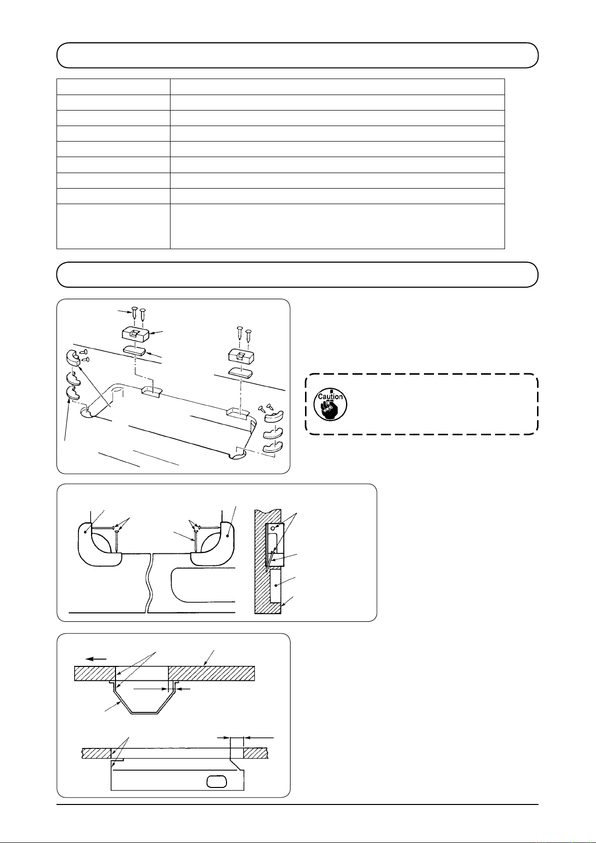
2. INSTALLATION
Nail
Support rubber of
the machine head
Rubber cushion
Support rubber of the
machine head
Nail
Hinge seat
Spacer rubber
Support rubber of the machine head
Nail
A
Small articles
case
(1) Attaching the hinge seats and support
rubber of the machine head
Fix th e hinge seats and th e support ru bbers
supplied with the machine on the table using nails.
When driving nail A, drive it slantingly
so that it does not pass through the
side of the small articles case.
Nail
A
Small articles
case
Top surface of
the machine table
Operator’s side
1
Align
Align
Table
20 mm
(2) Attaching the oil pan
Fix oil pan 1 supplied with the machine on the
table in 8 places with wood screws.
50 mm
− −
Page 5
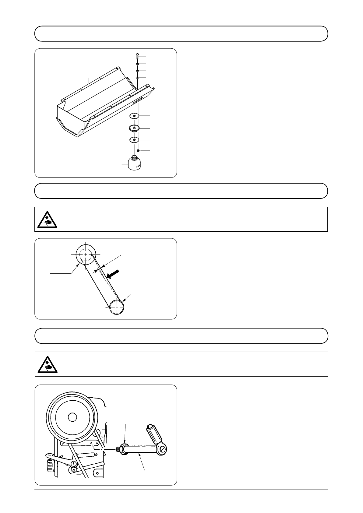
3. INSTALLING THE WASTE OIL CONTAINER
4
5
Oil pan
8
5
2
1
3
6
7
4. ADJUSTING THE BELT TENSION
WARNING :
To avoid possible personal injury due to abrupt start of the machine, turn off the power to the
machine and check to be sure that the motor has totally stopped rotating in prior.
) Attach drain plug 1, oil seal 2 and washer 3 to
the oil pan. Attach packing 5 and washer 8 to
screw 4 and x them with nut 6.
2) After they are xed, screw in waste oil container
into drain plug 1.
7
Adjust the belt tension with the height of the motor so
that the belt sags 5 mm when the center of V belt is
applied with a 9.8N load.
Handwheel
15mm
9.8N
Motor pulley
5. INSTALLING THE SYNCHRONIZER SUPPORT ROD
WARNING :
Turn OFF the power before starting the work so as to prevent accidents caused by abrupt start of
the sewing machine.
) Attach synchronizer support rod 1 to the arm
using attaching nut 2.
2
1
− 2 −
Page 6
6. ATTACHING THE BELT COVER
Notch (upper)
B
4
4
1
2
Notch (lower)
A
3
5
) Fix belt cover (rear) 1 on the arm with screws 2.
2) Fit belt cover (front) 3 to notch (upper) A and
notch (lower) B of the belt cover (rear).
3) Fix belt cover (front) 3 with screws 4 and 5.
4) Fix belt cover auxiliary plate 6 at the position of
0 mm from the rear end with wood screws 7
when there is a clearance of 2.5 mm between the
belt cover and the auxiliary plate.
5) When tilting the machine head, loosen wood
screws 7 and move the belt cover auxiliary plate
in the direction of the arrow until it stops. Then, tilt
the machine head.
6
7
2.5 mm
10 mm
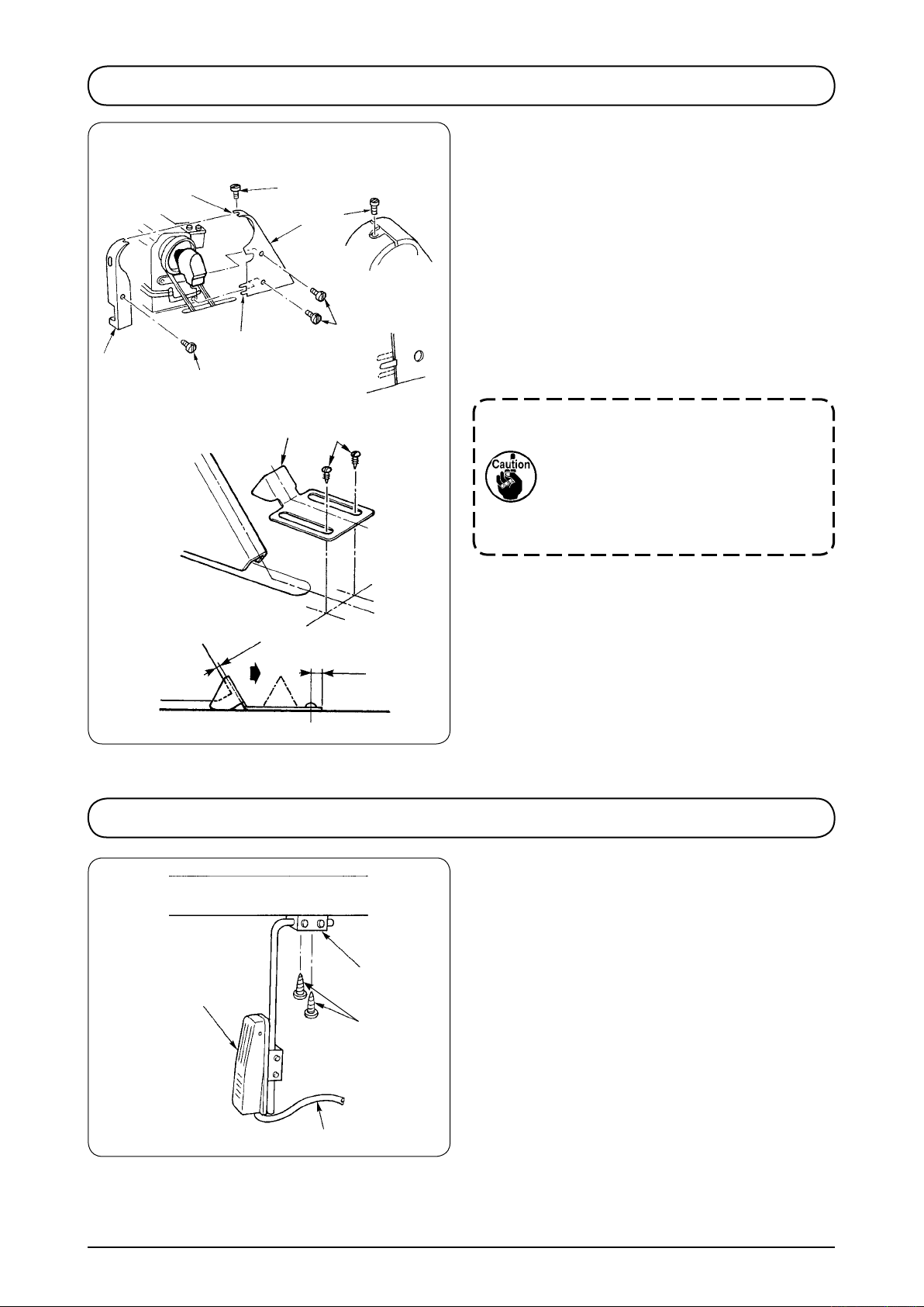
7. INSTALLING THE KNEE SWITCH
2
1
3
Afterattachingthebeltcover,conrm
whether or not the respective cords do
not come in contact with the belt and
the handwheel. Disconnection of the
cords will result when they come in
contact with one another.
) Attach supporting base 2 of knee switch 1 onto
the underside of the table using wooden screws
.
3
2) Fix cord 4 to an appropriate position on the table
using a staple supplied with the machine so as to
prevent the cord from hindering the operation.
4
− 3 −
Page 7
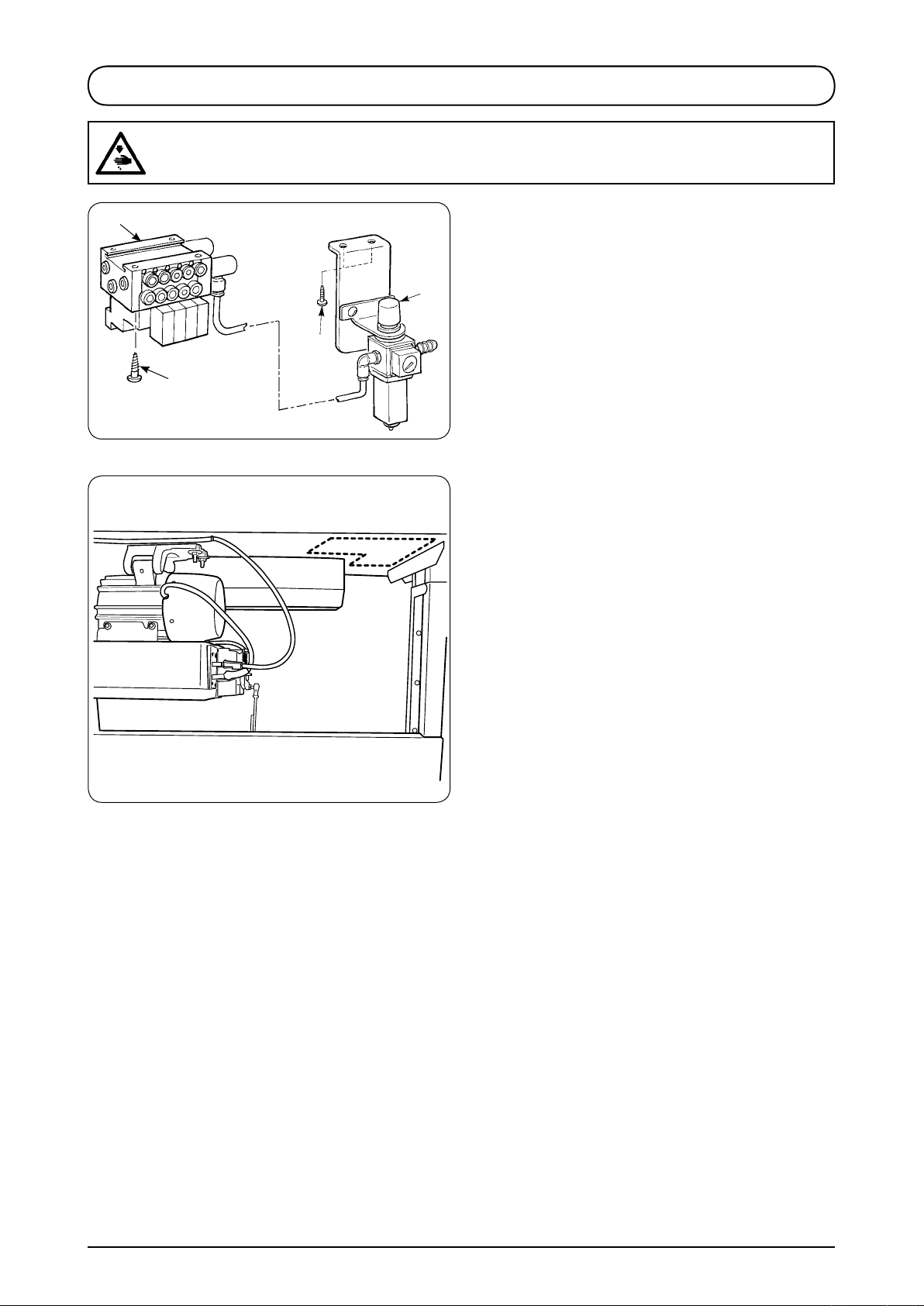
8. INSTALLING THE AIR DRIVE UNIT
WARNING :
Turn OFF the power before starting the work so as to prevent accidents caused by abrupt start of
the sewing machine.
3
4
Rear view of table
2
1
(1) Installing the air control unit
) Install regulator (asm.) 1 on the bottom surface
of the table with wood screw 2 supplied as
accessories.
2) Install air control unit (asm.) 3on the bottom
surface of the table in four places with wood
screws 4 supplied as accessories.
3) Install regulator (asm.) 1 and air control unit
(asm.) 3 in the broken line frame as shown in
the illustration on the left side. Determine the
installing position where it is convenient to the
user.
− 4 −
Page 8
1
2
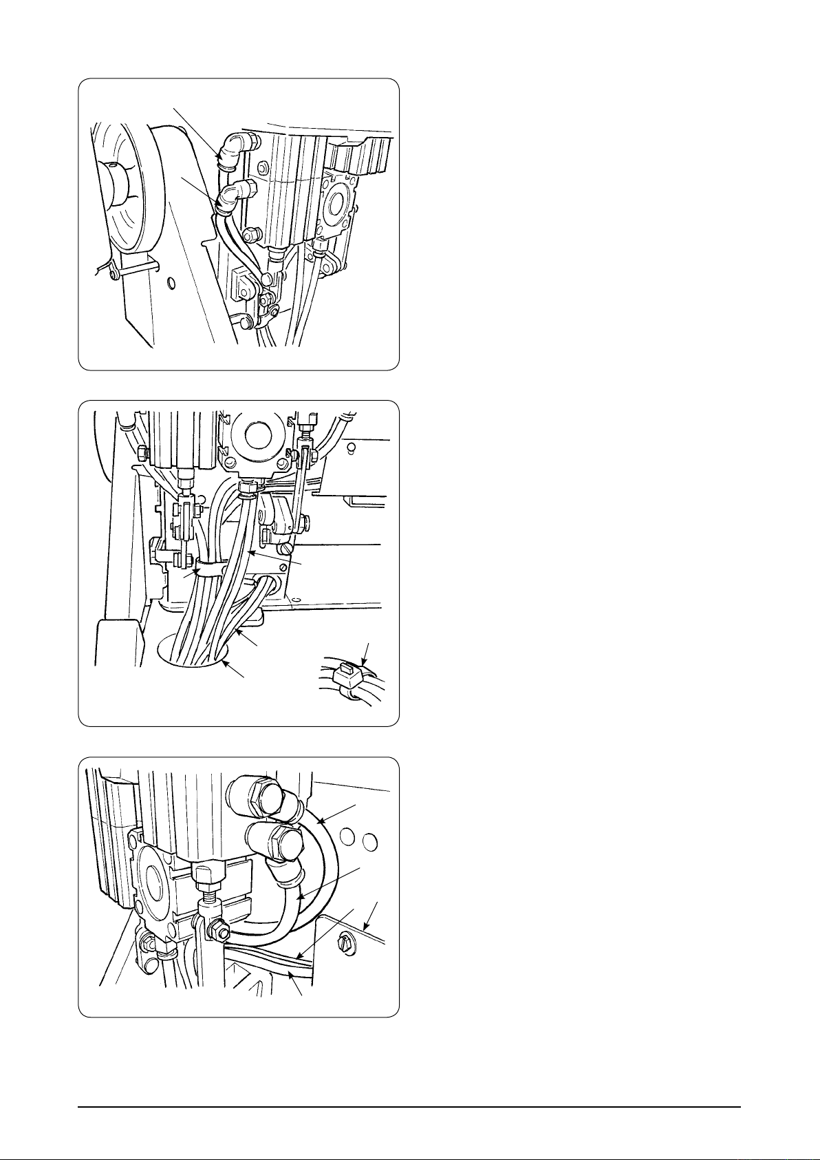
(2) Connecting the air hose
) Connect the air hoses coming from the air control
unit to the air cylinders of the sewing machine
as shown in the illustration. Adjust the seal Nos.
pasted on the hoses to those pasted on the joints,
and connect as described in the list.
Be sure to pass the hoses through hole !0 in the
table.
After connecting them, bundle air hoses 1, 2, 5,
, and C, 6-stage switch cord 6 using cable clip
B
of the machine head.
!1
Directly pass air hoses 7 and 8 through hole !0
in the table.
2) Pass air hoses 3, 4 and 9 coming from the
sewing machine through hole !0 bin the table,
and connect them to the air control unit.
(There are clip bands in the accessories. Use
them to arrange the air hoses if necessary.)
!1
349
!0
78
Clip band
C
B
!2
5
6
− 5 −
Page 9
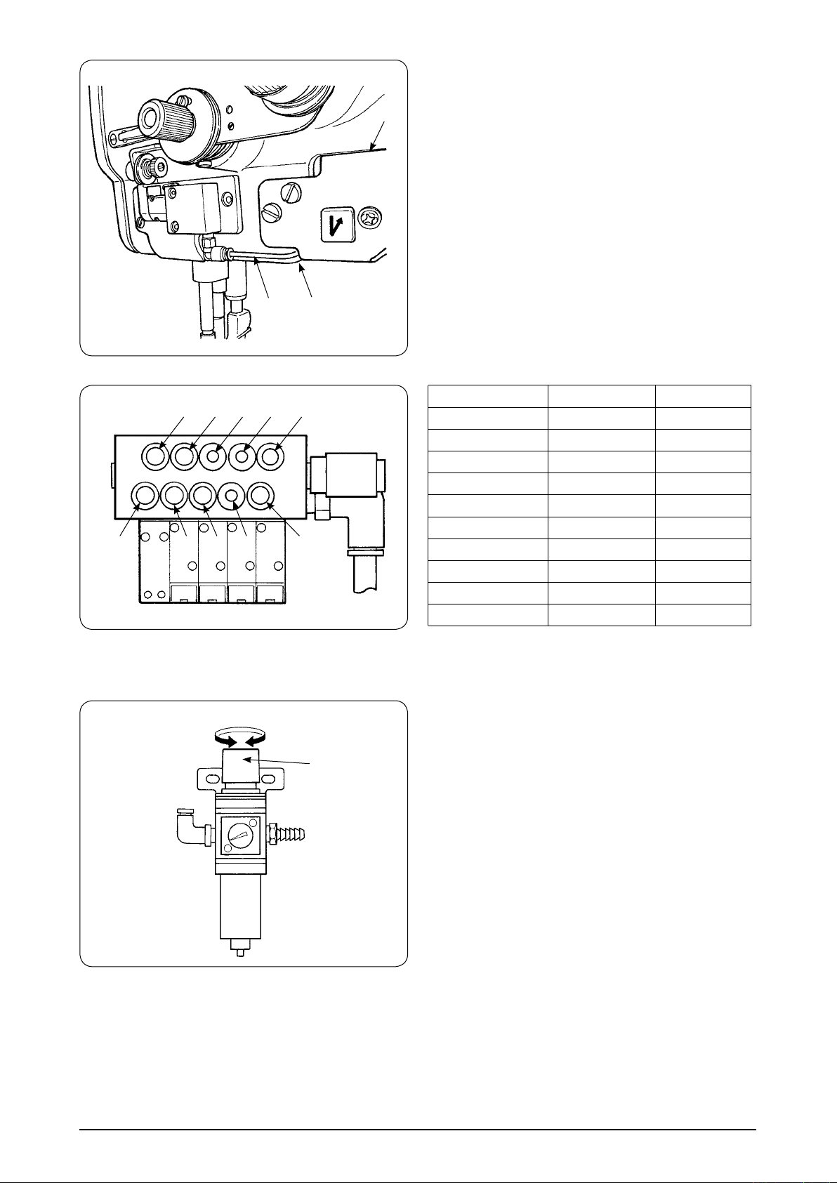
!3
3) Pass air hoses 5 through cord cover !2 the same
as 6-range switch cord 6, pass them through
clearance A between 6-range switch !3 and the
machine arm, and connect them to the joint of air
hoses 5.
C
5
B
8 9 4
Decrease Increase
5
7 3 1
2
A
1
Solenoid valve Cylinder
Condensation
BT
Thread trimming
Thread trimming
Thread clamp
FL
FL
DL
2P
2P
1 1
2 2
3 3
4 4
5 5
7 7
8 8
9 9
B B
C C
(3) Adjusting the air pressure
Adjust the air pressure to 0.4 to 0.5 MPa using air
pressure regulating knob 1 of regulator. Pull knob
up and turn it to properly adjust the operating
1
air pressure. After the adjustment, press the knob
down into the home position.
− 6 −
Page 10
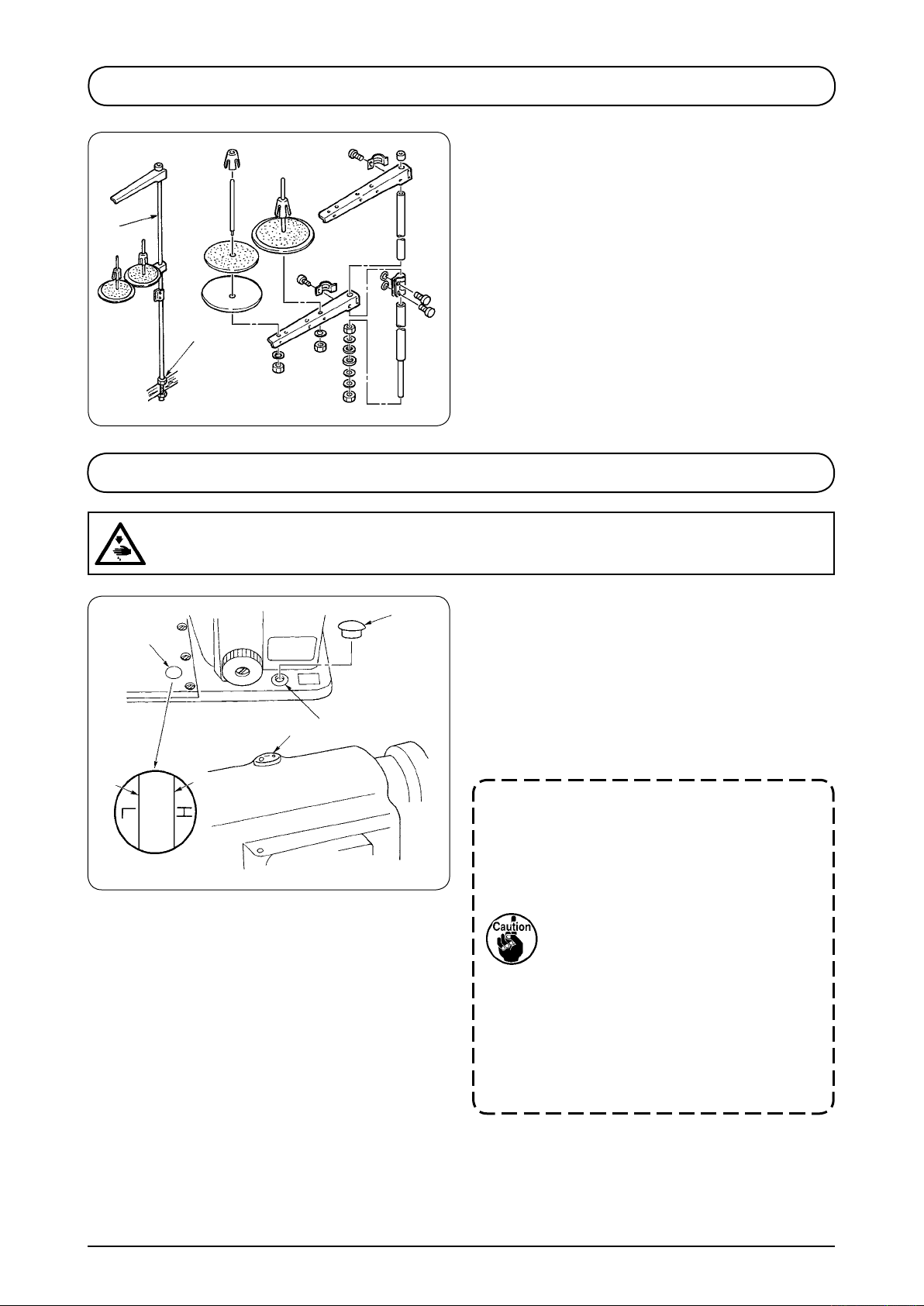
9. INSTALLING THE THREAD STAND
) Assemble the thread stand and set it to the hole
2) Tighten locknut 1 to x the thread stand.
3) When ceiling wiring is possible, pass the power
2
1
10. LUBRICATION
WARNING :
Turn OFF the power before starting the work so as to prevent accidents caused by abrupt start of
the sewing machine.
of the table.
cord through spool rest rod 2.
4
2
3
LU-2220N-7
Oil window
1
5
) Pour the JUKI New Defrix Oil No. into the oil
tank in the bed from lubrication hole 1 until H
level 3 of oil gauge 2 is reached.
2) Add the same lubricating oil as soon as the oil
level has come down to L level 4.
3) After the lubrication, operate the sewing machine
and check that the oil rises up to the oil sight
window.
1. Do not use any lubrication oil other
thanthespeciedtype.Besureto
close cap 5 of the oil hole.
2. When you operate your machine
forthersttimeaftertheset-upor
after an extended period of disuse,
apply two or three drops of oil to
the sections indicated with arrows.
(Refer to Fig. 1 on the next page.)
3. To use the machine that has been
disused for an extended period
of time, run in the machine for
approximately 10 minutes at 1,800
rpm.
− −
In the case where the machine is operated with
¡
the hook lled with normal amount of oil, the
oil level descends from H level to the L level in
approximately 00 hours .
Page 11
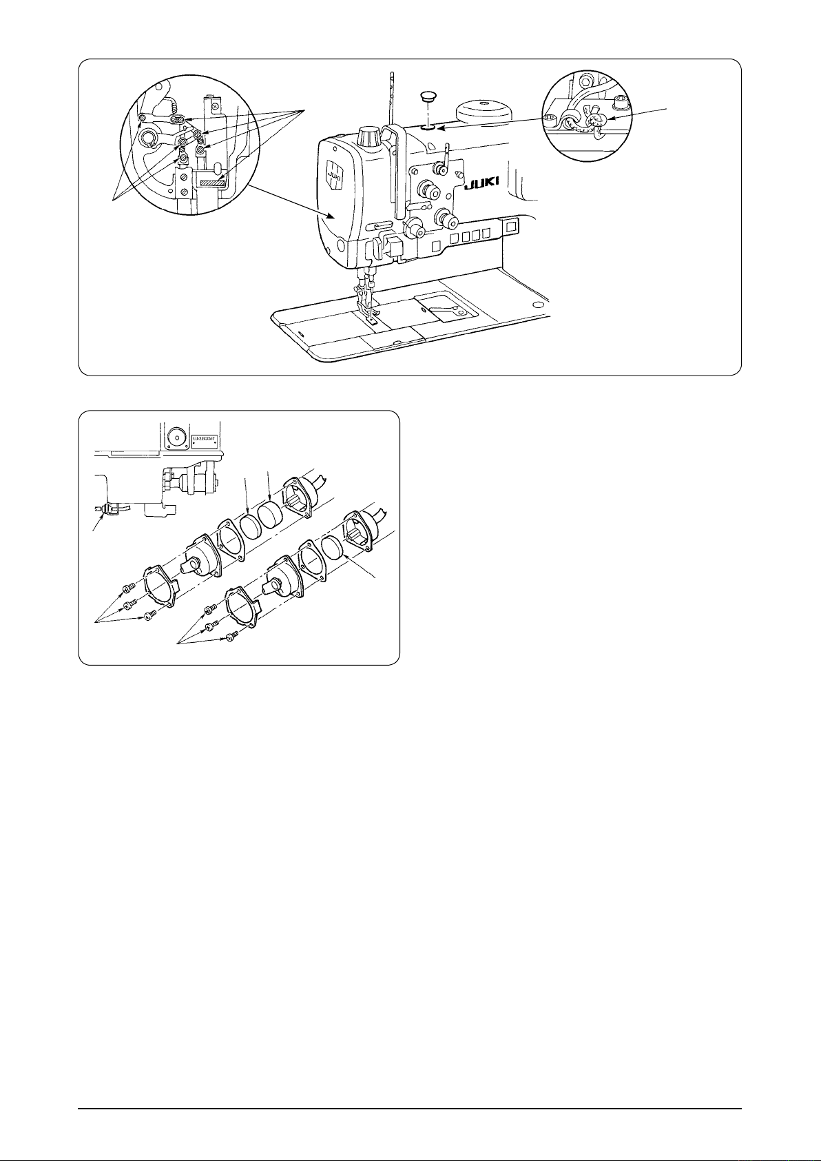
Supply oil
Filter
7
8
Supply oil
Supply oil
Flg.1
[Cleaningthelter]
) Approximately once a month, remove screws 6
from the lter case and clean magnet 7 and lter
element 8 inside the lter.
2) If the lter is clogged with soil, circulation failure
will result.
This will give rise to oil leakage from the upper
portion of the hook driving shaft saddle.
6
7
6
− 8 −
Page 12

11. ATTACHING THE NEEDLE
WARNING :
Turn OFF the power before starting the work so as to prevent accidents caused by abrupt start of
the sewing machine.
Use a SCHMETZ 34 x 35R needle.
) Turn the handwheel to bring the needle bar to the
2
1
Long groove
highest position of its stroke.
2) Loosen needle clamp screw 2, and hold needle
so that the long groove in the needle is facing
1
exactly to the left.
3) Push the needle 1 deep into the needle clamp
hole until it will go no further.
4) Tighten needle clamp screw 2 rmly.
12. ATTACHING/REMOVING THE BOBBIN
WARNING :
Turn OFF the power before starting the work so as to prevent accidents caused by abrupt start of
the sewing machine.
) Lift latch 1 of hook, and take out the bobbin.
2) Put the bobbin into the shaft in the hook correctly
and release the latch.
1
− 9 −
Page 13

13. THREADING THE HOOK
WARNING :
Turn OFF the power before starting the work so as to prevent accidents caused by abrupt start of
the sewing machine.
) Pass the thread through thread path 1 in the
hook and thread hole 2 in the lever, and draw the
thread.
Now, the thread will be brought to the thread hole
via the tension spring.
2
Make sure that the bobbin revolves in the
•
direction of the arrow when you draw the thread.
2
1
14. INSTALLING THE THREAD GUIDE
(1) Installing the needle thread guide rod
1
2
) Install needle thread guide rod 1 with nut 2.
2
1
(2) Installing the bobbin winder thread
guide
) Attach bobbin winder thread guide 1 to the
bobbin winder on the machine arm using screws
.
2
2) Adjust the position of the thread guide referring to
“15. WINDING A BOBBIN”
.
− 0 −
Page 14

15. WINDING A BOBBIN
WARNING :
Turn OFF the power before starting the work so as to prevent accidents caused by abrupt start of
the sewing machine.
A
5
F
D
4
3
G
H
B
C
1
E
2
) Pass the thread in the order, A through H. Then
wind it several turns round the bobbin.
2) Tilt bobbin presser 1.
3) Adjust bobbin thread amount adjustment screw 2
to wind a bobbin about 90% of its capacity.
Turn the screw counterclockwise to increase the
amount of thread to be wound round the bobbin,
or clockwise to decrease it.
4) If the bobbin is wound unevenly, correct it by
moving thread guide 3 of the bobbin winder back
or forth.
Then tighten screws 4.
5) When the bobbin is lled up, the bobbin presser
automatically releases the bobbin and the bobbin
winder stops running.
16. ADJUSTING THE AMOUNT OF OIL IN THE HOOK
WARNING :
Turn OFF the power before starting the work so as to prevent accidents caused by abrupt start of
the sewing machine.
) Adjust the amount of oil in the hook by turning
oil amount adjustment screw 1 mounted on the
hook.
2) Turning the adjustment screw clockwise will
decrease the amount of oil in the hook or
counterclockwise will increase it.
3) Place a piece of paper near the periphery of the
hook, and run the machine for approximately ve
seconds. The proper amount of oil in the hook is
obtained when the oil spots lightly make stripes
on the paper as shown in the gure.
1
A piece of paper
− −
Page 15

17. THREADING THE MACHINE HEAD
WARNING :
Turn OFF the power before starting the work so as to prevent accidents caused by abrupt start of
the sewing machine.
Needle thread
Threading method :
draw the thread to the operator's side.
L
Thread the machine head following the order of A
through to P as shown in the illustration given above.
A
G
B
E
K
M
C
D
F
N
N
P
H
I
J
O
− 2 −
Page 16

18. ADJUSTING THE STITCH LENGTH
Tu r n standard f e e d adjusting di a l 1 or 2P feed
adjusting dial 3 counterclockwise or clockwise so that
3
2
1
the number corresponding to the desired number is
brought to the top of the dial until the marking spot is
reached.
When turning 2P feed adjusting dial
,besuretoconrmthat2Pswitchis
3
OFF.
The scale 3 or less of 2P feed adjusting
dial (place where the dial stops with
the dial stopper) is for adjusting the 2P
feedadjustingdialto"0"point.
The scale 3 or less cannot be used.
For the details of 2P device, refer to
"30.OPERATIONSWITCHES".
19. THREAD TENSION
B
B
A
1
A
2
3
C
D
[Reversefeedstitching]
) Press down reverse feed control lever 2.
2) Reverse feed stitching can be performed as long
as you keep pressing the lever down.
3) Release the lever, and the machine will run in the
normal feed direction.
(1) Adjusting the length of thread
remaining after thread trimming
Turn thread tension nut No.
to shorten the length of thread remaining after
thread trimming. Turn the nut counterclockwise B
to lengthen it.
clockwise A
1
(2) Adjusting the needle thread tension
Turn thread tension nut No. 2
to increase the needle thread tension, or
A
counterclockwise Bto decrease it.
clockwise
2
(3) Adjusting the bobbin thread tension
Turn tension adjustment screw
to increase the bobbin thread tension, or
C
counterclockwise Dto decrease it.
clockwise
3
− 3 −
Page 17

20. THREAD TAKE-UP SPRING
(1) When you want to change the stroke
5
3
1
4
2
IncreaseDecrease
21. HAND LIFTER / HANDHEBEL
of the spring :
) Loosen screw 2 in the stopper, and move
stopper 3 to the right or left to change stroke of
thread take-up spring 1.
2) Move the stopper to the right to increase the
stroke of the thread take-up spring, or the left to
decrease it.
(2) When you want to change the tension
of the spring :
) Loosen nut 4, and move spring stud 5
counterclockwise to increase the tension of the
spring, or clockwise to decrease it.
) When you want to keep the presser foot in the
lifted position, turn hand lifter
the arrow. This makes the presser foot rise 9 mm
and stay at that position.
2) To make the presser foot come down to its home
position, lower the hand lifter.
in the direction of
1
1
22. ADJUSTING THE PRESSURE OF THE PRESSER FOOT
WARNING :
Turn OFF the power before starting the work so as to prevent accidents caused by abrupt start of
the sewing machine.
) Turn presser spring regulating dial 1 clockwise
to increase the pressure of the presser foot, or
counterclockwise to decrease it.
(Be sure to operate the sewing machine with the
pressure of the presser foot minimized as long as
the presser foot securely holds the material.)
1
Decrease
Increase
− 4 −
Page 18

23. NEEDLE-TO-HOOK RELATION
WARNING :
Turn OFF the power before starting the work so as to prevent accidents caused by abrupt start of
the sewing machine.
2
4
1.4 mm
1
2.0 mm
0.02 - 0.1 mm
) Adjust the standard feed adjusting dial to "0".
2) Loosen hook driving shaft set collar clamping screw 3, and turn the handwheel counterclockwise to make
the needle bar ascend by 2.0 mm from the lowest position of its stroke.
3) In the state described in 2), align blade point 1 of the hook with the center of needle 2, and tighten hook
driving shaft set collar clamping screw 3. At this time, a clearance of .4 mm is provided between the blade
point of the hook and the top end of the needle eyelet. (As reference, the handwheel pointer meets the
marker line of the scale L on the handwheel.)
4) Loosen screw 4 in the top face of the bed and screw 5 in the hook driving shaft saddle, and adjust so
that a clearance of 0.02 to 0. mm is provided between the blade point of hook and the needle by moving
the hook driving shaft saddle to the right or left. Once the specied clearance is obtained, securely tighten
screws 4 and 5.
5) Set the standard feed adjusting dial to maximum value, and check that the blade point of the hook does not
come in contact with the needle.
3
5
The operation panel could come in contact with the thread stand when tilting the machine
head. To protect the relevant parts from contact, shift the thread stand to a position at which
the thread stand does not interfere with the control panel.
24. ADJUSTING THE HOOK NEEDLE GUARD
WARNING :
Turn OFF the power before starting the work so as to prevent accidents caused by abrupt start of
the sewing machine.
When a hook has been replaced, be sure to check
1
0.15 - 0.2 mm
2
2
3
the position of the hook needle guard.
As the standard position of the hook needle guard,
hook needle guard 2 must push the side face of
needle 1 to lean the needle by 0.5 to 0.2 mm away
from its straight position. If not, adjust the hook
needle guard by bending it.
) If you want to move the hook needle guard
inwards, turn adjusting screw 3 clockwise.
2) If you want to move the hook needle
guard outwards, turn adjusting screw 3
counterclockwise.
− 5 −
Page 19

25. ADJUSTING THE BOBBIN CASE OPENING LEVER
WARNING :
Turn OFF the power before starting the work so as to prevent accidents caused by abrupt start of
the sewing machine.
) Turn the handwheel to move bobbin case opening
lever 1 in the direction of the arrow A, and
loosen screw 2.
6
C
E
5
A
B
D
3
26.
ADJUSTING THE THREAD TRIMMING MECHANISM COMPONENTS
4
1
E
2
F
0.1 - 0.3 mm
2) Turn the handwheel to move bobbin case opening
lever 1 in the direction of arrow B, and loosen
screw 3.
3) Turn bobbin case 4 in the direction of arrow C
to until bobbin case stopper 5 rests in groove D
on throat plate 6. In this state, adjust so that a
clearance of 0. to 0.3 mm is provided between
top end E of bobbin case opening lever and
protrusion F on the bobbin case when they
approach most. Then, tighten screws 2 and 3.
WARNING :
Turn OFF the power before starting the work so as to prevent accidents caused by abrupt start of
the sewing machine.
(1) Positioning the thread trimming cylinder joint
Th read tr immi ng cylinder 1 and thread trimm ing
cylinder joint 2 have to be assembled as shown in the
gure on the left side.
2
1
7.0 ± 0.5 mm
(2) Adjusting the position of the feed dog
Install the feed dog in terms of the window hole of the
throat plate to the position below on condition that the
standard feed dial : P = 0.
Lateral direction : Clearance between the left and
5.7 ± 0.2 mm
P=0
A
A = B
B
•
right is equal (center of the window hole of throat
plate)
Longitudinal direction : Clearance on the operator
•
side is 5.7 ± 0.2 mm.
− 6 −
Page 20

(3)-1. Counter knife
3
4
9.0 ± 0.5 mm
(Adjusting the travel amount) (Positioning of the counter knife base stopper)
) Turn the handwheel to adjust the thread take-up
lever to the lower dead point, loosen counter knife
base stopper setscrew 4 and counter knife drive
arm clamp screw 2, and adjust the clearance
between thread trimming cylinder joint 3 and
joint stopper 4 to 9.0 ± 0.5 mm.
(At this time, the gauge for adjustment supplied
as accessories can be used.)
2) When the distance between the tip of counter
knife and the groove of machine bed is 3.8 ± 0.
mm, make the counter knife base and counter
1
knife base stopper come in contact a with each
other.
(At this time, gauge for adjustment supplied as
accessories can be used.)
37.8 ± 0.1 mm
Top surface of machine bed
37.8 ± 0.1 mm
Groove section
of slide plate
2
3) Tighten counter knife base stopper setscrew 1
and counter knife drive arm clamp screw 2.
a
Counter knife
Gauge for adjustment supplied as accessories
2.4 mm
43 mm
− −
Thickness : 0.6 mm
29 mm
26.8 mm
37.8 mm
9 mm
Page 21

(3)-2. Counter knife (Adjusting the lateral position)
) Loosen counter knife setscrews 1.
1
2
4
2.4 ± 0.15 mm
Counter knife
base
3
2) Set the feed dial to "0", adjust the thread take-
(Press the manual switch of solenoid valve
3) Keeping the state of 2), move counter knife 2 to
(At this time, the gauge for adjustment supplied
4) Release the manual switch of solenoid valve that
up lever to the lower dead point, and actuate the
solenoid valve by hand to mate the state that the
thread trimming cylinder is drawn.
No. 3 to make the state of lock. Refer to
Explanationofthesolenoidvalve"
"(12)
.)
the right and left. Then adjust the distance from
feed dog 3 to thread guide 4 to 2.4 ± 0.5 mm
and tighten counter knife setscrews 1.
as accessories can be used.)
has been actuated in (3) – 2 – 2). (Refer to
Explanationofthesolenoidvalve"
"(12)
.)
When installing the counter knife,
tighten the screws while pressing the
counter knife to the anti-operator side.
Gauge for adjustment supplied as accessories
2.4 mm
43 mm
Thickness : 0.6 mm
29 mm
26.8 mm
37.8 mm
9 mm
Conrmation:Actuatethesolenoidvalvebyhandtomovethethreadtrimmingaircylinderand
conrmthefollowingsinthestatethatthecounterknifebasecomesincontactwiththecounterknife
base stopper :
Distance between the tip of counter knife and the machine bed is 37.8 ± 0.1 mm.
•
Clearance between the cylinder joint and the joint stopper is 9.0 ± 0.5 mm.
•
Distance from the left end of feed dog to the thread guide is 2.4 ± 0.1 mm.
•
− 8 −
Page 22

(4) Moving knife (Adjusting the vertical position)
) Loosen moving knife drive arm clamping screw 1
1
and moving knife shaft thrust collar setscrew 2
and tighten them again after adjusting the vertical
direction of moving knife 3. When tightening
moving knife drive arm clamping screw 1,
perform the items (), (8), (9) and (0) that are
mentioned later.
0.5 to 0.6 mm
2
Throat plate
3
2) The vertical position of moving knife is the
position where the clearance between the bottom
surface of throat plate (reverse side) and the top
surface of moving knife 3 is 0.5 to 0.6 mm.
(At the time of adjustment, the gauge for
adjustment supplied as accessories can be used.)
Gauge for adjustment supplied as accessories
2.4 mm
43 mm
Thickness : 0.6 mm
− 9 −
29 mm
26.8 mm
37.8 mm
9 mm
Page 23

(5) Counter knife (Adjusting the vertical position)
) Loosen counter knife base clamping screw 1,
1
To align with the
top surface of
moving knife
adjust it to the position where the upper end of
the blade section of counter knife 2 aligns with
the top surface of moving knife 3, and tighten the
screw again. (At this time, be careful of the blade
point of hook. It is safe to work while adjusting the
main shaft angle to the position near L engraved
marker line.)
2
3
(6) Thread guide installing position
To align the top
surface of thread
guide with the top
surface of moving
knife.
3
1
2
) Loosen thread guide setscrews 1 and tighten
them again after adjusting the position of thread
guide 2.
Installing position : The top surface of thread
guide 2 should align with the top surface of
moving knife 3 in the vertical direction and the
thread guide should be xed after fully moving it
to the direction of the arrow mark as shown in the
gure in the longitudinal direction.
− 20 −
Page 24

(7) Adjusting the knife pressure
29.0 to 30.0 mm
1
) Adjust the thread take-up lever to its lower dead
point, and actuate the solenoid valve by hand to
make the state that the thread trimming cylinder
is drawn.
(Press the manual switch of solenoid valve
No. 3 to make the state of lock. Refer to
Explanationofthesolenoidvalve"
"(12)
.)
2) Keeping the state of ), slowly turn the handwheel
by hand, and adjust the distance of R section of
the moving knife and the end of machine bed to
the position of 29 to 30 mm.
(At this time, the gauge for adjustment supplied
as accessories can be used.)
3) Loosen moving knife setscrews 1 and tighten
them again after adjusting the knife pressure.
4) Release the manual switch of solenoid valve that
has been actuated in () – ). (Refer to
Explanationofthesolenoidvalve"
"(12)
.)
*1 : When the knife pressure is low, tighten
moving knife setscrews 1 while lightly
pressing the moving knife to the counter
knife. When the knife pressure is high, worn-
out or damage of the blade section will be
caused . So, adjust the knife pressure as low
as possible.
*2 : When thread cannot be cut even when the
knife pressure is increased, change the height
of moving knife or counter knife within the
range of adjustment and adjust so that the
blade sections meet together. The height of
moving knife and counter knife should be a
clearance of 0.5 to 0.6 mm between the knife
and the bottom surface of throat plate.
Gauge for adjustment supplied as accessories
2.4 mm
43 mm
− 2 −
Thickness : 0.6 mm
29 mm
26.8 mm
37.8 mm
9 mm
Page 25

(8)-1. Initial position of the moving knife drive arm and the moving knife
) Tilt the sewing machine and actuate the solenoid
valve by hand in the state that the thread trimming
cam roller is not entered the cam groove to make
the state that the thread trimming cylinder is
pushed out.
(Press the manual switch of solenoid valve
No. 4 to make the state of lock. Refer to
Explanationofthesolenoidvalve"
2) Loosen moving knife return plate setscrews 1
and remove moving knife return plate 2.
3) Loosen moving knife drive arm stopper nut 3 and
loosen moving knife drive arm stopper screw 4.
4) Loosen moving knife drive arm clamping screw 5.
5) Adjust the clearance between the thread trimming
cam roller and the periphery of thread trimming
cam to 0.05 to 0.5 mm, and adjust moving knife
to the initial position.
6
The initial position of moving knife is the position
where the distance between the top end of
moving knife and the machine bed is 26.8 ± 0.
mm.
(At this time, the gauge for adjustment supplied
as accessories can be used.)
6) Keeping the state of 5), tighten moving knife drive
arm clamping screw 5.
(Tightening torque : 5.9 to 6.9 N•m)
At this time, for the vertical direction of moving
knife drive arm, both ends of the bottom surface
of moving knife drive arm and the lower end of
moving knife shaft align with each other.
1
26.8 ± 0.1 mm
2
3
4
5
Clearance between the
periphery of thread trimming
cam and the thread trimming
cam roller is 0.05 to 0.15 mm.
"(12)
.)
Top surface of machine bed
26.8 ± 0.1 mm
Groove section of slide plate
6
To be continued to (8) – 2 Adjusting the clearance
between the moving knife drive arm and the
moving knife drive arm stopper
Gauge for adjustment supplied as accessories
2.4 mm
43 mm
Thickness : 0.6 mm
29 mm
26.8 mm
37.8 mm
− 22 −
9 mm
Page 26

(8)-2. Adjusting the clearance between the moving knife drive arm and the moving knife
drive arm stopper
) Maintaining the clearance of 0.05 to 0.5 mm
1
2
Clearance between the moving knife
drive arm and the moving knife drive
arm stopper is 0.05 to 0.1 mm.
between the thread trimming cam roller and the
periphery of thread trimming cam, adjust moving
knife drive arm stopper screw 1 to make a
clearance of 0.05 to 0. mm between the moving
knife drive arm and the moving knife drive arm
stopper, and tighten it with moving knife drive arm
stopper nut 2.
To be continued to (8) – 3. Installing position of
the moving knife return plate
(8)-3. Installing position of the moving knife return plate
) Maintaining the clearance of 0.05 to 0. mm
between the moving knife drive arm and the
moving knife drive arm stopper, make the moving
knife return plate come in contact with the return
pin and x it with moving knife return plate
setscrew 1.
2) Release the manual switch of solenoid valve that
has been actuated in (8) – - . (Refer to
1
Moving knife return plate aligns
with the returning pin. (Contact)
Whenthemachinelockhasoccurredduringthreadtrimmingoperation,conrmwhetheror
not the adjustment values of (8)-1 to 3 are proper.
When they are not proper, it is necessary to perform re-adjustment.
Explanationofthesolenoidvalve"
"(12)
.)
− 23 −
Page 27

(9) Adjusting the thread trimming cam timing
Pointer on handwheel
Scale on handwheel
1
Close
contact
) Loosen thread trimming cam setscrews 1 and
tighten them again after adjusting the position of
thread trimming cam 2.
2) The position of thread trimming cam is the
position where thread trimming cam roller 3
comes in contact with R section where it starts
entering the cam groove when the position of
handwheel is at L engraved marker line.
Conrmation:Makesureagainofthepositionof
L engraved marker line and R section where
the roller starts entering the cam groove after
xingthethreadtrimmingcam.
2
3
− 24 −
Page 28

(10) Installing position of the clamp spring
1
43.0 to 43.5 mm
When there is a clearance between the clamp
spring and the moving knife at the initial
position of moving knife, bobbin thread
cannot be clamped after thread trimming.
) When the moving knife is at the initial position,
loosen clamp spring setscrews 1, make the
clamp spring come in contact with the moving
knife and tighten it with clamp screw setscrews 1.
(Tightening torque : 0.2 to 0.3 N•m)
The distance between the clamp spring and the
end of machine bed becomes 43.0 to 43.5 mm.
(At this time, the gauge for adjustment supplied
as accessories can be used.)
At the time of adjustment, be careful of the
contact of the clamp spring and the hook, and the
contact of the clamp spring and the moving knife
when it moves to its forward travel end.
* When using the clamp spring for optional thin
thread, adjust the adjustment value to 43.5
mmandxtheclampspringwhilemaking
it strongly come in contact with the side of
moving knife.
Move of moving
knife
Be careful of the contact of clamp
spring and moving knife when it
moves to its forward travel end.
Gauge for adjustment supplied as accessories
2.4 mm
43 mm
Thickness : 0.6 mm
29 mm
26.8 mm
37.8 mm
* When the position of the clamp spring cannot
be adjusted even clamp spring setscrews 1 are
loosened, loosen clamp spring base setscrews 2
and move clamp spring base 3 to the operator's
side to adjust.
(The position in vertical direction of the clamp
spring base has to be placed to the hook shaft
base. Therefore, tighten the clamp spring base
with setscrews 2 while lightly pressing it in
downward direction.
9 mm
3
2
− 25 −
Page 29

(11) Adjusting the condensation amount
1
3
A
) Loosen lock nut 3 of reverse feed cylinder
knuckle joint 2.
2) Adjust the clearance between the top end of
reverse feed cylinder rod 1 and the end of
reverse feed cylinder knuckle joint 2 referring to
the standard of the table. (It is possible to adjust
by turning rod 1.)
3) After the adjustment, tighten lock nut 3.
Conrmation:
1. Perform the thread trimming sewing in
practice.
2. Conrmthatthecondensationamount(pitch
before one stitch of thread trimming) is proper
( * ) in accordance with the sewing conditions.
2
Dimension A
Condensation
amount
(Standard)
.5 mm .5 mm
2.0 mm 2.0 mm
* The length of thread remaining on the
cloth side is shortened by decreasing the
condensation amount. When the amount is
excessively decreased, however, the cloth is
tore by the seams and the stitch skips. As a
result, thread trimming trouble occurs.
In addition, when the amount is excessively
increased, thread-handling trouble occurs. As
a result, thread trimming trouble occurs.
Condensation amount of 1.5 to 2 mm is
recommended.
− 26 −
Page 30

(12) Explanation of the solenoid valve
8
9 4 2
Condensation
1
BT
2
Thread trimming ON (Cylinder is drawn.)
3
Thread trimming OFF (Cylinder is pushed out.)
4
Thread clamp (Cylinder is pushed out.)
5
AK (Presser foot rises.)
7
AK (Presser foot lowers.)
8
DL (Cylinder is pushed out.)
9
) 2P
B(C
C
BC7 5 3 1
With regard to the switch of solenoid valve (Manual)
) By pressing the switch (green) inside the cover,
the solenoid valve can be actuated by hand.
B
57 3 1
8 9 4
2
2) By turning the switch in the direction of the arrow
mark while pressing it, it is possible to lock.
By turning the switch in the reverse direction of
the arrow mark, it is possible to release the lock.
* WhenturningONthepower,conrmthatall
covers of the solenoid valve are closed.
(Under the state that the manual switch is
locked, the covers are not closed and it is
possible to prevent the malfunction of the
solenoid valve.)
− 2 −
Page 31

27. ADJUSTING THE LIFTING AMOUNT OF THE PRESSER FOOT AND THE WALKING FOOT
1
The lifting amount of the presser foot and the walking
foot is adjusted using dial 1. Turn the dial clockwise
to increase the lifting amount or counterclockwise to
decrease it.
28. SEWING SPEED TABLE
The maximum sewing speed has been specied in accordance with sewing conditions as shown in the table
below. Set the maximum sewing speed appropriately in accordance with the sewing conditions given taking
care not to exceed the corresponding specied value.
(1) Max. sewing speed in accordance with the amount of the alternating vertical
movement of the walking foot and the presser foot
) When stitch length is 6 mm or less, the max. speed
has to be the upper limit value or lower limit value.
4000
3500
3000
2500
2000
1500
1000
500
0
Revolutions per minute (rpm)
1 1.5 2 2.5 3 3.5 4 4.5 5 5.5 6 6.5
Amount of alternate vertical movement
of walking foot and presser foot (mm)
Upper
limit
value
Lower
limit
value
2) When stitch length is more than 6 mm and 9
mm or less
Amount of alternate vertical
movement of walking foot
and presser foot
Revolutions
per minute
to 6.5 mm 2000 rpm
29. RESETTING THE SAFETY CLUTCH
WARNING :
Turn OFF the power before starting the work so as to prevent accidents caused by abrupt start of
the sewing machine.
The safety clutch functions when an excessive load
is applied to the hook or the other components during
sewing.
While the safety clutch if functioning, the hook will
never rotate even if turning the handwheel.
) Reset the safety clutch with the sewing machine
2
1
A
2) Fit screwdriver (medium) 2 supplied with the
3) Holding screwdriver 2 by hand to prevent
4) The resetting procedure completes when the
− 28 −
tilted.
machine as an accessory in hole A in safety
clutch bushing 1.
safety clutch bushing 1 from rotating, turn the
handwheel in the reverse direction of rotation.
handwheel clicks.
Page 32

30. OPERATION SWITCHES
One-touch type reverse feed switch
1
• While the machine is in operation, the machine
performs reverse feed stitching as long as this
switch is held pressed, and resumes normal feed
stitching when the switch is released.
• If this switch is pressed while the machine is at
rest, the feed will be set to the reverse feed state.
31 2 4 6
Alternating vertical movement amount change-over switch
2
If this switch is pressed the amount of the alternating vertical movement of the walking foot and the presser
foot will be maximized. (Lamp above the switch lights up)
Use this switch when a multilayered portion of the sewing product is not smoothly fed.
When performing the alternating vertical movement amount change-over with the knee switch, x the
knee switch supplied with the machine on the table with wood screws and use it. For the wiring, refer to
“INSTRUCTION MANUAL (SUPPLEMENT) for sewing machines for leather and heavy-weight materials”.
Automatic reverse feed stitching cancellation/addition switch
3
• If this switch is pressed when the following automatic reverse feed stitching has been specied, the reverse
stitching will not take place (for once immediately after it is pressed). (Example )
• If this switch is pressed when no automatic reverse feed stitching has been specied, the reverse feed
stitching will take place (once immediately after it is pressed). (Example 2)
5
(The sewing machine does not run.)
If it is released, the feed will return to the normal
feed state.
(Example 1) In the case where both automatic reverse feed stitching for start and that for end have
beenspecied:
A
B
C
D
If the switch is pre ssed befor e st artin g
sewing, the automatic reverse feed stitching for
start (between A and B) will not be carried out.
(Example 2) In the case where neither automatic reverse feed stitching for start nor that for end
havebeenspecied:
C
D
If the switch is pressed during sewing, the
automatic reverse feed stitching for end (between
C and D) will not be carried out.
A
B
A
B
C
D
A
B
If the switch is pre ssed befor e st artin g
sewing, the automatic reverse feed stitching for
start (between A and B) will be carried out.
− 29 −
C
D
If the switch is pressed during sewing, the
automatic reverse feed stitching for end (between
C and D) will be carried out.
Page 33

Needle lifting switch
4
If this switch is pressed, the machine will travel from the needle-down stop position to the needle-up stop
position.
When raising the machine head which has been tilted, do not hold the operation switch to
raise it.
Example
2P feed adjusting dial scale : 6
¡
Standard feed adjusting dial scale : 9
¡
If this switch is pressed, stitch length is changed
¡
over from 9 to 6.
2P switch
5
If this switch is pressed, the stitch length is
changed over to that of the scale on the feed
adjusting dial. (Lamp in the button is lit up.)
Be sure to make the number of 2P feed
adjusting dial less than that of the
standard feed adjusting dial.
OFF ON
\
If this switch is pressed again, stitch length
¡
returns from 6 to 9.
− 30 −
Page 34

ON OFF
Needle thread clamp switch
6
When the needle thread clamp switch is turned
ON, the needle thread clamp motion is performed
at the start of sewing, and when it is turned OFF,
the needle thread clamp motion is not performed.
However, the needle thread clamp device as well
as the presser foot lifting motion does not function
until the thread trimming is performed after turning
ON the power.
In addition, when the presser foot is lifted after
thread trimming motion, the needle thread is
clamped with the needle thread clamp device, but
when the needle thread clamp switch is turned
OFF, the needle thread is released.
Needle thread clamp switch can be set
to effective or ineffective by setting of
the motor.
For the details, refer to the Instruction
Manual (Supplement) for SC-510.
31. KNEE SWITCH
If k n ee sw i t ch 1 is pr e ssed, the am o u nt of the
alternating vertical movement of the walking foot and
the presser foot will be maximized. (Same with the
performance carried out by pressing the alternating
vertical movement amount change-over switch “ ”
1
on the machine head.)
The knee switch can be used as the
presser lifting switch by setting of the
motor. (When the switch is used as
the presser lifting switch, the function
as the alternating vertical movement
amount changeover switch is lost.)
For the details, refer to the Instruction
Manual (Supplement) for SC-510.
32. CAUTIONS WITH REGARD TO THE SEWING OPERATION
. Be sure to perform the sewing operation after conrming that the needle bar position (needle UP stop
position/needle DOWN stop position) when the sewing machine stops is properly positioned.
(For the setting of the designation of needle bar position, refer to the Instruction Manual (supplement) for SC-50.)
2. Perform a trial sewing and conrm the nished state of sewing since the state at the start of sewing is
different from that at the end of sewing in accordance with the sewn product (material and thread).
3.
When using the needle thread clamp device, use it together with the reverse feed stitching at the start of sewing.
4. Be sure to perform the thread trimming motion on the cloth.
− 3 −
Page 35

33. TROUBLES IN SEWING AND CORRECTIVE MEASURES
Troubles Causes Corrective measures
. Thread
breakage
(Thread frays
or is worn out.)
(Needle thread
trails 2 to 3 cm
from the wrong
side of the
fabric.)
2. Stitch skipping
Thread path, needle point, hook
1
blade point or bobbin case resting
groove on the throat plate has
sharp edges or burrs.
Needle thread tension is too high.
2
Bobbin case opening lever
3
provides an excessive clearance at
the bobbin case.
Needle comes in contact with the
4
blade point of hook.
Amount of oil in the hook is too
5
small.
Needle thread tension is too low.
6
Thread take-up spring works
7
excessively or the stroke of the
spring is too small.
Timing between the needle and the
8
hook is excessively advanced or retarded.
Timing between the needle and the
1
hook is excessively advanced or
retarded.
Pressure of the presser foot is too low.
2
The clearance provided between
3
the top end of the needle eyelet and
the blade point of hook is not correct.
Hook needle guard is not functional.
4
Improper type of needle is used.
5
Remove the sharp edges or burrs on the
藺
blade point of hook using a ne emery
paper. Buff up the bobbin case resting
groove on the throat plate.
Decrease the needle thread tension.
藺
Decrease the clearance provided between
藺
the bobbin case opening lever and the
bobbin. Refer to
BOBBIN CASE OPENING LEVER.”
Refer to
藺
RELATION.”
Adjust the amount of oil in the hook
藺
properly. See
AMOUNT OF OIL IN THE HOOK.”
Increase the needle thread tension.
藺
Decrease the tension of the spring and
藺
increase the stroke of the spring.
Refer to
藺
RELATION.”
Refer to
藺
RELATION.”
Tighten the presser spring regulator.
藺
Refer to
藺
RELATION.”
Refer to
藺
NEEDLE GUARD.”
Replace the needle with one which is thicker
藺
than the current needle by one count.
“23. NEEDLE-TO-HOOK
“23. NEEDLE-TO-HOOK
“23. NEEDLE-TO-HOOK
“23. NEEDLE-TO-HOOK
“24. ADJUSTING THE HOOK
“25. ADJUSTING THE
“16. ADJUSTING THE
3. Loose stitches
Bobbin thread does not pass through
1
the tension spring of the inner hook.
Thread path has been poorly
2
nished.
Bobbin fails to move smoothly.
3
Bobbin case opening lever provides
4
too much clearance at the bobbin.
Needle thread tension is too low.
5
Bobbin thread tension is too low.
6
Bobbin has been wound too tightly.
7
Thread is thick.
8
Thread supplying amount of thread
9
take-up lever is excessively large.
− 32 −
Thread the bobbin thread correctly.
藺
Remove rough parts with a ne emery
藺
paper or buff it up.
Replace the bobbin or hook with a new
藺
one.
Refer to
藺
CASE OPENING LEVER.”
Increase the needle thread tension.
藺
Increase the bobbin thread tension.
藺
Decrease the tension applied to the bobbin
藺
winder.
Replace the feed dog with one for thick
藺
thread.
Remove the pre-tension of needle thread
藺
clamp device.
Increase the needle count.
藺
Move the thread take-up thread guide to
藺
the right side to decrease the supplying
amount by the thread take-up lever.
“25. ADJUSTING THE BOBBIN
Page 36

Troubles Causes Corrective measures
4. Thread slips off
the needle eyelet
simultaneously with
thread trimming.
5. Thread slips off the
needle eyelet at the
start of sewing.
6. Defective sharpness
at the time of thread
trimming.
Thread tension given by the
1
tension controller No. 1 is too
high.
Thread tension given by the
1
tension controller No. 1 is too
high.
Clamp spring has improper
2
shape.
Bobbin thread tension is too low.
3
The blades of moving knife and
1
counter knife have been
improperly adjusted.
The knives have blunt blades.
2
Needle thread tension is too low.
3
Bobbin thread tension is too low.
4
Decrease the thread tension given by the
藺
tension controller No. 1.
Decrease the thread tension given by the
藺
tension controller No. 1.
Replace the clamp spring with a new one
藺
or correct the current one.
Increase the bobbin thread tension.
藺
Refer to
藺
THREAD TRIMMING MECHANISM
COMPONENTS”
Replace the moving knife and counter
藺
knife with new ones, or correct the current
ones.
Increase the needle thread tension.
藺
Increase the bobbin thread tension.
藺
“26. ADJUSTING THE
.
7. Thread is not
trimmed.
8. Thread breaks at the
start of sewing after
thread trimming.
9. Stitch skipping occurs
at the start of sewing
after thread trimming.
Initial position of the moving
1
knife has been improperly
adjusted.
Bobbin thread tension is too low.
2
Position of the thread guide is
3
improper.
Torque at the time of cutting
4
thick thread is insufficient.
The needle thread is caught in
1
the hook.
Bobbin thread is not clamped
1
after thread trimming.
Position of the thread guide is
2
not proper.
Number of revolutions is too fast
3
and needle thread cannot catch
bobbin thread.
Bobbin thread tension is too low.
4
Refer to “Adjusting the initial position of
藺
the knife” in the Engineer’s Manual.
Increase the bobbin thread tension.
藺
Refer to
藺
position.”
When using thick thread equivalent to #4
藺
or #5, delay the UP stop position.
Refer to "Function No. 112" of the
Instruction Manual for SC-510.
Shorten the length of thread remaining
藺
on the needle after thread trimming.
Refer to
Check again the installing position of
藺
clamp spring.
When thread is thin,replace theclamp
藺
spring with one for thin thread.
Refer to
藺
position.”
Increase the number of stitches of soft
藺
start at the setting of motor.
Refer to "Instruction Manual for SC-510".
Increase the bobbin thread tension.
藺
“26. (6) Thread guide installing
“19. THREAD TENSION.”
“26. (6) Thread guide installing
− 33 −
 Loading...