

Page 1
CYLINDER-BED, 1-NEEDLE, UNISON-FEED lOCKSTITCH
MACHINE (WITH
A VERTICAl-AXIS tiOOK)
1
®
I
I
----
NOTE : Read safety instructions carefully and understand them
before using your
Retain this Instruction Manual for future reference.
LS-341
N.
No.02
29176906
Page 2
---------
IMPORTANT SAFETY INSTRUCTIONS
----
Congratulations on
To
get the most
correctly.
Please read
Please remember
this
1. Observe the basic safety measures, including, but
2.
Read all the instructions, including, but not limited
keep
this
3.
Use the machine after
4.
All safety devices must be in position when the machine is ready
specified
5.
This machine shall be operated
6.
For
your
7.
For the following, turn
7-1
For threading needle(s), looper, spreader etc. and replacing bobbin.
7-2 For replacing part(s)
guide etc.
7-3
For repair work.
When leaving the working place
7-4
7-5 When using
8.
If you should allow oil, grease, etc. used with the machine and devices
swallow any
9.
Tampering with the live parts and devices, regardless
10.
Repair, remodeling and adjustment
personnel. Only
11. General maintenance and inspection
12. Repair and maintenance
the audit and guidance
Whenever you
13. Before making repair and maintenance
the
air
compressor
residual air
are
only
personnel.
14. Periodically clean the machine
your
purchase
out
of
the many
Instruction Manual carefully before use.
to
keep
this
Instruction Manual so that
it
safety devices
personal protection, we recommend that you wear safety glasses.
off
clutch motors
of
such liquid by mistake, immediately wash the contacted areas and consult a medical doctor.
spare parts designated by JUKI can
of
find a failure
has
pressure after disconnecting the air comp1ressor from the machine has
adjustments
and
of
a JUKI machine.
functions
manual in a safe place.
has been ascertained that
is
not allowed.
by
the power switch
of
needle,
without
works
of electrical components shall be conducted by qualified electric technicians
specially skilled personnel.
of
any
to
be detached from the machine and the compressed air
performance
throughout
of
this
machine and operate it in safety, it
We
hope you will enjoy the use
not
limited
to
this
you
may read
appropriately-traine~d
presse1r
or
works
of
foot, throat plate, looper, spreader, feed dog,
when the
applying brake, it has
must
works
electrical components, immediately stop the machine.
works
checks
the period
it
at anytime when necessary.
it
conforms
or
disconnect the power plug
working
of
only
be done by appropriately trained technicians
be
have
to
be done
on the machine equipped with pneumatic parts such as an air cylinder,
done
of
to
Instruction Manual before you use the machine. In addition,
operators.
place
to
whether the machine is powered, is prohibited.
used
for
by
by
appropriately
use.
is
necessary
of
your
the following ones, whenever you use the machine.
with safety rules/standards valid in
for
work
or in operation. The operation without the
of
the machine from
is
unattended.
be
waited until the
to
come
repairs.
appropriately trained personnel.
iru
trained
motor
stopped totally.
contact with
supply
to
be expelled. Exceptions
technicians
machine
th1~
neeoHe
has
to
to
use
this
machine
for
a long time.
your
country.
receptacle.
guard, folder, cloth
~rour
eyes
or
skin
or
specially skilled
or
under
be
cult
off. Existing
to
<Or
specially
skilled
or
this
15. Grounding the machine
in an environment that is free from
16. An appropriate power plug has
to
a grounded receptacle.
17. The machine is
18. Remodel
measures. JUKI assumes
or
only
modify
is
always necessawy
to
allowed
the machine in accordance with the safety rules/standards while taking all the effective safety
to
be
n.o
responsibility
19. Warning hints are marked with the
Danger of injury to operator
A
Items requiring special attention
&
strong
be attached
u·sed
two
noise sources such as high-frequency welder.
for
the purpose intended. Other used are not allowed.
shown symbols.
for
the
no1rmal
to
the machine by electric technicians. Power plug has
for
damag1e
or
service staff
operation
caused by remodeling
of
the machine. The machine has
or
modification
to
to
be
of
the machine.
be operated
connected
-j-
Page 3
-----FOR
1.
Keep
yourr
hands away from needle when you
machine is in operation.
2.
During operation, be careful
come close
do
not
3
..
Do
not
removed.
4.
Before tilting the mach
attached
5.
Before tilting the machine
confirm
and
6.
Tilt the machine head after removing the
7.
When having tilted the machine head, wipe
lbed
support
8.
"fo ensure safety, never operate the machine with the ground wire
removed.
9.
When inserting/removing the power plug,
advance.
10. In time
t:he
receptacle
·11.
If the machine is suddenly moved from a cold place
may be observed. In
(~onfirmed
12. lrurn OFF the power
13. Do
not
to
the thread take-up, handwheel, V-belt, bobbin winder and motor. Also,
place anything close
operate
of
allow the power cord
yom
to
your
machine head.
that the
and hinge area, and then raise up the machine head.
thunder and
so
as
that there is no danger
SAFE
machine with
nne
head, be sure
or
motor
to
to
of
~ightening,
ensure safety.
this
case,
the machine in
OPERATION---------
not
to
allow
to
them.
the~
removnng the V belt, be sure to
the sewing machine stops.
stop
turn
of
to
trail
tum
ON
your
or
any other person's head
finger guard, belt cover and any other protectors
to
confirm that the head support bar is
hook
for
the knee lifter.
out
oil on the bed underside, the
the
your
ON
water
the
on
the floor.
work
the
drops
event
power
power
switch
and disconnect the power plug from
to
a warm place, dew condensation
to
in the machine.
of
a power failure.
the power
tum
OFF the power switch
has
the
machine
switch
for
to
or
while
or
hands
pro_perly
top
the power
be turned OFF in
after
your
the
to
face
of
supply
have
-n-
Page 4
[!. SETTING UP THE SEWING MACHINE
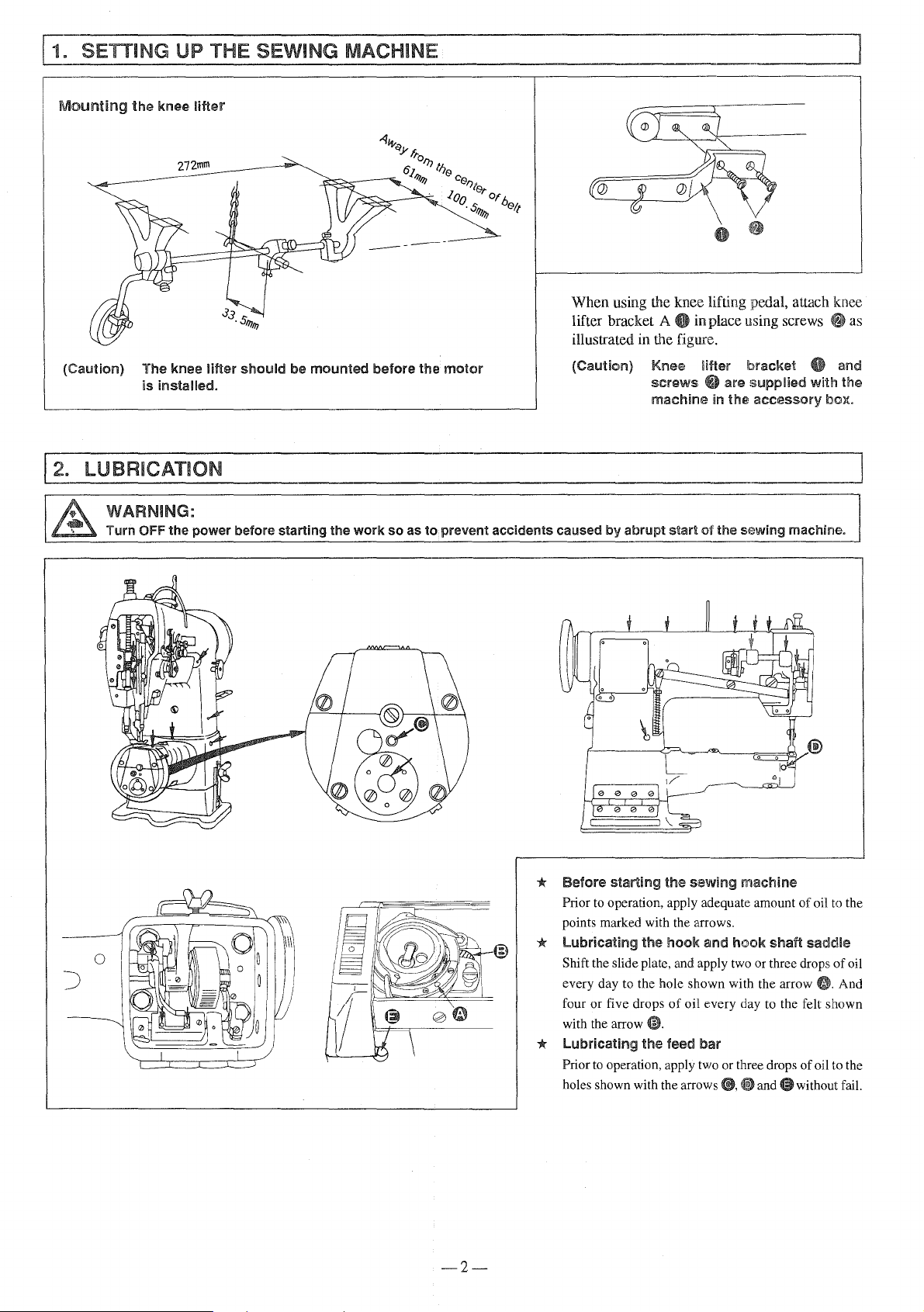
Mounting
(Caution)
j2.
LUBRICATION
the
WARNING:
Turn OFF
knee
The knee
is
installed.
the
power
lifter
lifter
should
before
be
mounted
starting
the
before
work
so
as
the
to
motor
prevent
accidents
When using the knee liifting pedal, attach knee
lifter bracket A
8 in place using screws as
illustrated in the figure.
(Caution)
caused
by
Knee
screws
machine
abrupt
start
iifler
~~
in
ol
the
bracket
are
supplied
the
accessory
sewing
8 and
with
machine.
the
box.
*
*
*
-2-
Before
Prior
points marked with the arrows.
Lubricating
Shift the slide plate, and apply two or three drops
every day to the hole shown with the arrow And
four or five drops
with the arrow
Lubricating
Prior
holes shown with the arrows
starting the sewing
to
operation, apply adequate amount
the
hook
of
oil every day to the felt shown
and
machine
hook
4D.
the
feed
bar
to
operation, apply two or three drops
(i,
(g
and@
of
shaft
without fail.
oil
saddle
of
oil to the
to
of
the
oil
Page 5
j3,
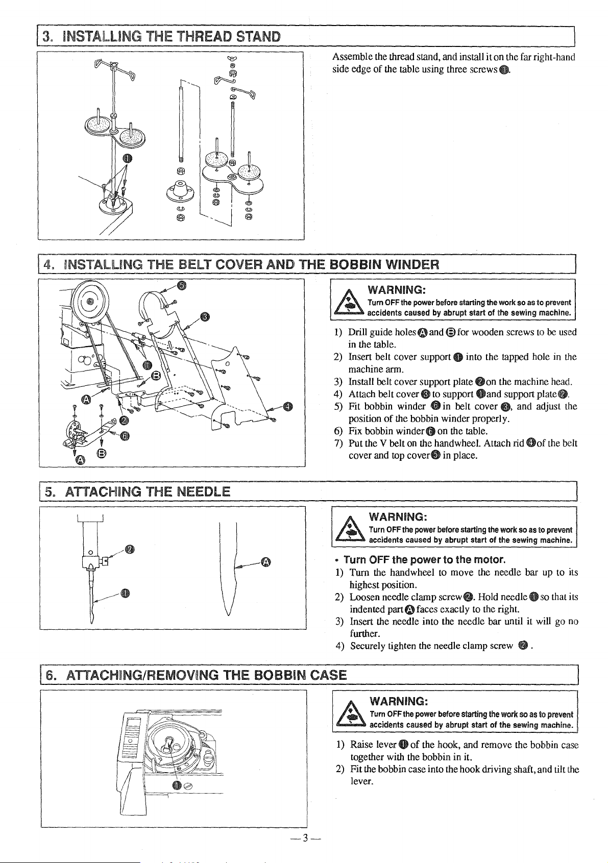
INSTALLING
THE
THREAD
STAND
!4.
~NSTALUNG
THE BELT COVER AND THE BOBBIN WINDER
Assembk
side edge
the thread stand, and install it on the far right-hand
of
the table using three screws
WARNING:
Turn
OFF
accidents caused by abrupt start
1)
Drill guide
in the table.
2) Insert belt cover support
machine arm.
3) Install belt cover support plate
4) Attach belt
5) Fit bobbin winder 8 in belt cover
position
6) Fix bobbin
7) Put the V belt
cover and top
the power before starting the work so as
holeseand@for
of
wooden screws
0 into the tapped hole in the
f)
on the machine head.
cover@! to support
of
the bobbin winder properly.
winder@ on the table.
on
the hand wheel. Attach rid
cover8
in place.
Oand
Q.
to
the sewing machine.
support plate
@!,
prevent
to
be used
f).
and adjust the
Gof
the belt
ATTACHING THE NEEDLE
~
5.
-
__Q_]B;/-8
'-tlr
:....--~
~~·
[s.
ATTACHING/REMOVING THE BOBBIN CASE
.A
• Turn OFF the
1)
2) Loosen needle clamp screw
3)
4) Securely tighten the needle clamp screw
~----------------------------------,
WARNING:
Turn
OFF
accidents caused by abrupt start
Turn the handwheel
highest position.
indented
Insert the needle into the needle bar until it will go no
further.
the power before starting the work so as to prevent
power
part(i.) faces exactly to the right.
to
the motor.
to
move the needle bar up to its
of
the sewing machine.
f).
Hold needle 0 so that its
@.
WARNING:
Turn
OFF
the power before starting the work so as
of
accidents caused by abrupt start
1)
Raise lever 0
together with the bobbin in it.
2) Fit the bobbin case into the hook driving shaft, and tilt the
lever.
of
the hook, and remove the bobbin case
the sewing machine.
to
prevent
-3-
Page 6

11.
WINDING A BOBBIN
Is.
PLACING A BOBBIN IN
TH~
BOBBIN CASE
1)
Route the thread in the order
winding it round the bobbin several times.
bobbin
2) Set
with the belt.
3) Adjust
round the bobbin so that the bobbin is wound with thread
about 80%
incn·--ase
counterclockwise to decrease it.
4)
If
thread is wound unevenly round the bobbin, move
winder tension adjuster base
thread is evenly wound round the bobbin.
5) The moment the bobbin has been wound up, the bobbin
presser is released, and the bobbin winder
automatically.
presserOdown
screw8to
of
its capacity.
the amount
adjust the amount
of
thread wound round the bobbin, or
of~,@
to
bring the winder in contact
Tum
the screw clockwise
0
to
the right or left so that
of
thread to
and
@before
be
wound
will stop
to
WARNING:
Turn
OFF
the
power
before
starting
the
work
so
as
to
prevent
accidents
1)
Hold a bobbin so that the end
the bobbin is directed
case.
2) Pass the thread in threading slit
it under the tension spring and draw
(Caution)
caused
by
to
As
long
as
the
the
bobbin
tion ~ makes
case,
@.
abrupt start
the right and put it into the bobbin
bobbin
the
of
the
sewing
machine.
of
the thread wound round
4itin the bobbin case, route
it out from notch
is
pulling
b<>bbin
correctly
the
rotate
thread
in
placed in
in direc-
direction
8.
19.
THREADING THE MACHINE HEAD
WARNING:
Turn
OFF
the power before starting the
Thread the
in
the
machine
order
as
illustrated
of 0 through
~.
in
the
work
figure
so
as
to
prevent accidents caused
by
abrupt start
of
the sewing machine.
-4-
Page 7

!10. ADJUSTING
THE
STITCH LENGTH
!11. THREAD TENSION
Tum stitch length dial 8 counterclockwise or clockwise
bring the desired value
is aligned with
the pin.
to
the top
of
the dial so that the value
* Reverse feed stitching
1)
Push down feed
2) The machine performs reverse feed stitching as long
the lever is held depressed.
3) The moment you release
the normal stitching mode.
leverfj.
the lever, the machine resumed
* Adjusting the needle thread tension
Tum tension nut No. 2 8 clockwise
crease
(toward@) to decrease it.
the needle thread tension, or counterclockwise
(toward~)
to in-
* Adjusting the bobbin thread tension
Tum tension
the bobbin thread tension,
@)
to decrease it.
screw@
clockwise (toward@) to increase
or
counterclockwise (toward
to
as
@.
THREAD TAKE-UP SPRING
* To change the stroke
1)
Loosen screw@ in the stopper, and move stopper8lto
right
or
left.
2) Move the stopper
thread take-up spring, or to the left to decrease it.
* To change the
spring
Loosen
increase the tension
it. Fit a screwdriver in
tum it until the desired tension is provided.
nutO.
~ension
Tum spring shaft 0 counterclockwise to
of
thread take-up spring 8
to
the right to increase the stroke
of
the thread take-up
of
the spring,
the groove in the spring shaft and
or
clockwise to decrease
of
the
the
--5-
Page 8

113. ADJUSTING THE PRESSURE OF THE PRESSER FOOT
@.
ADJUSTING THE PRESSER FOOT
r----
J!\ND
,
Adjust the pressure
type
of
material to
spring regulator: 25 mm)
1) Turn pressure spring regulator
increase the pressure
wise (toward@) to decrease
2) After lhe adjustment, securely tighten
lator
..
of
the presser foot in accordance wilh the
be
used. (Standard height
Oclockwise
of
the presser foot,
it.
THE WALKING FOOT :
* Operating height
presser
The operating height
foot has been adjusted to the marker
the top feed crank. A better
adjusting
presser foot.
""
o Highest position
o Lowest position
foot
the operating height
Loosen nut
boss accordingly.
of
the walking
of
the walking foot and the presser
result may be obtained by
of
G.
and change the position
-> The stroke is
---J>
The stroke is minimized.@
of
the pressure
(toward~)
or
counterclock-
nut@
of
ffoot
and the
of"
1/8" engraved on
the walking foot and the
of
the cam rod
maximized.~
to
the regu-
l
* Alternate vertical
and presser foot
The alternate vertical strokes
presser foot are normally equaL
1)
Loosen screw 8
2) Bring
~
the thread take-up lever to its highest position,
and lower the presser bar lifting lever.
Move
top feed crank
of
the presser foot,
motions
of
the top feed crank.
@to
or
to the
of
the walking foot
of
the walking foot and
left~
to increase the stroke
right@
to increase it.
-6-
Page 9

[
15.
HEIGHT OF THE FEED
DOG
j16.
NEEDLE-TO-HOOK RELATIONSHIP
WARNING:
Turn
OFf
the power before starting the
work
0
so
as
-0.05mm
to
Feed dog
the surface
to be adjusted according the sewing conditions or after the
feed dog is replaced, follow the procedure described below.
1) Maximize the feed dog height.
2)
3)
4)
prevent accidents caused by abrupt start
Adjust lhe timing between the needle and the hook following
the procedure described below.
I) Set
2) Turn the hand wheel to bring the neeqle bar to the lowest
* Det,ermine the height
3) The standard height
Ohas
been factory-adjusted
of
throat plate@. When the feed dog height needs
Loosen screw 8
Adjust the feed dog height comparatively higher than the
standard height, and temporarily
Now, adjust the height
securely tighten the screw 0
1tbe
feed regulating dial to "3".
position
screwO.
of
in
the feed dog.
of
the feed dog appropriately, and
its stroke, and loosen needle bar connection
of
of
the needle bar is obtained when a
distance
needle eyelet and blade point 0
needle ascends 2.4 mm from the lowest position
stroke.
(The lowest position
of
1.
7 mm is provided between the
of
the needle bar
reference)
Distance from the bottom face
the bottom end
*
Det1ermine
4) Loosen
@and
5)
In the state described in 3), loosen screw 8
driving shaft saddle and move the hook driving shaft
saddle to the right or left until a clearance
is provided between the blade point
screw@
loosen screws
of
the needle bar: 55.2 mm
the
position
in the gear cover@, remove gear cover
of
Oand
fi. After the adjustment, securely tighten the screw.
6) Then, align the blade point
the needle, and tighten screw e
7) Tum the handwheel clockwise and alternately tighten
screws(!) little by little.
(Never tighten either screw only.)
of
to
jut
outl
mm from
fix
it
at that position.
in
the feed dog.
of
the sewing machine.
the needle bar.
LOp
end
of
of
the hook when the
of
for
of
the needle bar frame to
the
hook
(i)in the large bevel gear.
in
the hook
of 0 to
0.05
of
the hook and needle
the hook with the center
in
the gear.
the
its
mm
of
-7-·
Page 10

117.
ADJUSTING THE NEEDLE GUARD OF THE HOOK
the
-
work
so
as
to
_
prevent
I
accidents
After replacing the hook, be sure to confirm the position
needle guard. The standard position
obtained when needle
the side face
adjust
ingly.
1) To bend the needle guard inward, apply a screwdriver
2) To bed the needle guard outward, apply a screwdriver
caused
the position
the outside
the inside
WARNING:
Turn
OFF the
power
before
starting
j_
[
__________
USTING THE BOBBIN CASE OPENING
WARNING:
Tt~m_Off
the
power
before
starting
the
work
so
as
to
prevent
accidents
1)
2)
caused
Tum
the handwheel in its normal rotational direction to
bring bobbin case opening lever
tion.
Tum
bobbin case @ in the direction
stopper8comes
0.
3) Loosen
ment plate and move bobbin case opening lever adjustment plate
clearance
bobbin case opening lever
the bobbin case.
screw8in
--
by
abmpt
start
of
the
sewing
of
guard@lightly
of
needle as illustrated in the figure.
of
the needle guard
of
the needle guard.
of
the needle guard.
by
abmpt
start
in contact with the groove in throat plate
the bobbin case opening lever adjust-
8 in the direction
of
0.1 to 0.15 mm is provided between the
comes in contact with
by
.
of
the
sewing
4~to
of
the arrow so that a
and protruding section
machine.
the needle guard is
bending it accord-
-·--
machine.
its back end posi-
of
arrow @ until
J
of
the
If
not,
to
to
J
:
of
OJ.
ADJUSTING THE
LONGITUDINAl
POSITION OF THE NEEDLE BAR FRAME ]
* Adjusting the relationship between the top
feed rod and presser bar
1) Set the feed regulating dial to its minimum value.
2) Loosen clamping screw in
arm, and adjust the clearance between the top feed rod and
the presser bar to 7.5 mm.
(Caution) Take care
frame@.
not
* Adjusting the relationship between the feed
and the needle bar
dog
1)
Set
the feed regulating dial to its minimum value.
2) Loosen clamping screw in the feed rock
3) Adjust
comes
(slightly closer
the position
to the center
of
of
to the operator).
the needle bar frame rear
to
allow
any
play in needle bar
shaft crank.
the feed dog so that the needle
the
needle hole in the feed dog
-8-
Page 11

!20. SAFETY MECHANISM
WARNING:
Turn
OFF
accidents caused by abrupt start
If
the thread is
operation, the safety
is in
lower sprocket only.
* How
1)
Remove
2) Pressing
direction opposite to its normal rotational direction.
the power before starting the work so as
caught
in the hook while the sewing machine
mechanism
to
reset
the
thread
caught
in the hook.
push
button
8,
strongly
of
the sewing machine.
actuates to idle the
tum
the pulley in the
* Safety load
Tum
adjustment
incre-ase the safety load,
wise) to decrease it.
screw@
in
direction~
or
in direction
@(counterclock-
(clockwise) to
to
prevent
!21.
REPLACING THE TIMING BELT
.
-""-
I~
v
(D
\l
1\
,--
~
""'
~I
G)
-
-
G)
~
WARNING:
Turn
OFF
the power before starting the work so as to prevent
accidents caused by abrupt start
* How
1) Loosen
2)
3)
4)
* How
1) Installation is carried
2)
to
remove
screwOin
rear bushing (2), screw
clamping screws
0in
the
feed lever
Remove
bushingO.
Draw
timing
Remove
from the side
main shaft rear bushing.
To
driving shaft,
up
engraved on the hook driving shaft thrust
marker
ing
sproclk:ete.
handwheel
feed lever
belt
the timing belt from the
to
install
adjust the timing between the main shaft
to its
highest
line~)
(D.
In this state, insert the timing belt into lower
the
timing
the
hand
Oin
0 in the feed
shaft
8,
shaft
fi)until a clearance
8 to
come
off
window
tum
engraved
and pull
the
timing
out
the hand wheel to bring the thread take-
dead
belt
wheel,
the main shaft rear bushing,
lever
in the written order.
a11d
pull
is provided.
out
belt
analogously in reverse order.
point
and
on
hook
of
the sewing machine.
screws@in
shaft arm and screw
out
lower
it from the hole in the
the
driving
main shaft
main shaft rear
enough
sprocket, draw it
screw
to allow
and
the hook
No. 1
collar®
shaft rear bush-
G)
with
-9-
Page 12

@_i
1.
MOTOR PULLEY AND V
Use an M type V belt.
B!LT
2. The following table show the relationship between the motor pulley,
belt length and the rotational speed
of
the sewing machine.
_]
Rotational speed
of
sewing machine
Frequency
50Hz
2000 s.p.m
60Hz
The
effective
When
above.
your
diameter
machine
cr!
the
motor
pulley
uses a single-phase
is 5 mm
motor,
smail0r
apply the
IN SEWING AND CORRECTIVE
F--·
Trouble
-----~---
l.
Thread breakage
I
.
CD
The
thread path, needle point, blade point
I (Thread frays or hook or the stopper groove in the throat plate has
wears out.)
(Needle thread remains
to
3 em on the wrong ®
2
of
the cloth.) tension while it has an <:xcessively small stroke.
side
2. Stitch skipping
3. Loose stitches
(isolated idling
loop)
scratches.
The
1<2)
Q)
®
@
(J)
(j)
<2)
Q)
®
@
®
(J)
@
needle thread tension
The
clearance in the bobbin case opening lever is 0
too large.
The
needle comes in contact with the blade point
the hook.
The
needle thread tension is too low. 0
The
thread take-up spring has an excessively high 0
The
timing between the needle and hook too early 0
or too late.
The
clearance between the needle and the blade 0
point
The
timing between the needle and hook
or too late.
The
presser foot pressure is too low. 0
The
height
The
needle guard
The
size
Defective needle thread path.
The
hook has scratches.
(j)
The
<2)
Q)
®
@
®
thread path is
The
bobbin fails
The
clearance in the bobbin case opening lever is
too large.
The
bobbin thtead tension
The
bobbin thtead
the bobbin.
The
forked part
case is
Cause j
is
too high.
of
the hook
of
not
is
too large.
of
the needle bar is inadequate.
of
the hook does not function.
the needle is wrong.
poody
to
of
threaded.
finished.
rotate smoothly.
is
too low.
has
been
wound too tight round
the
t<ension
spring
of
of
the
is
too early 0
the bobbin
Outside diameter
of
motor
I
I
0115 mm
095mm
~-
than
'lhe
out,ide
belt
which
is i inch
-,.---···-------------·
Remove the scratches
I o 1
using a fine emery paper.
in the throat plate.
Adjust the needle thread tension properly.
0
Decrease the clearance in the bobbin case opening
lever. Refer
opening lever".
I o
of
Refer
Adjust the needle thread tension properly.
Decrease the tension
increase the stroke
Refer
Refer
Refer
Tighten the pressure spring regulator.
Refer
0
Refer to "17. Adjusting the needle guard
0
hook".
Replace the needle by one which
0
See "9. Threading the machine head".
0
Remove the scratches
0
using a fine emery paper.
Grind it using a fine emery paper, or
0
0 Replace the bobbin, or replace the hook.
See "18. Adjusting the bobbin case opening lever".
0
0 Properly adjust the bobbin thread tension.
Decrease the bobbin thread winding tension.
0
Correctly thread the bobbin case.
0
diameter.
than
Corrective
on
the blade point
Buff
to
"18. Adjusting the bobbin case
to
"16. Needl<Ho-hook relationship".
of
the thread take-up spring, and
of
the spring.
to
"16. Needle-to-hook relationship".
-
to
"16. Needle-to-hook relationship".
to
"16. Needle-to-hook relationship".
to
"16. Needle-to-hook relationship".
on
the blade point
Size
of
V belt
M57
lVI56
those
meas~nas
up the stopper groove
is
in the table
of
the hook
of
one count thicker.
of
the hook
buff
it up.
l
--~---
the
-10-
Page 13

MEMO
-------
-----------------
·-----------------------------·-----··-------
·--
·-------
--·---
Page 14

To order
or
for further information, please
contact:
JUKI
INTERNATIONAL SALES DIVISION
8-2-1, KOKURYO-CHO,
CHOFU-SHI, TOKYO
PHONE: 03 (3430)
FAX.
TElEX
CORPORATION
182, JAPAN
4001-5
03(3430) 4909·4914·4984
: J22967
L.
___
Please do not hesitate to contact our distributors or agents
*The
description covered in this instruction manual is subject
commodity without notice.
_
in
your area for further information when necessary.
to
change for improvement
96 • 04 Printed
in
Japan
of
the
(F)
 Loading...