

Page 1
BE98OOT0BOA
No.
00
V -
Model
HIGH
CYLINDER
LOCKSTITCH
INDUSTRIAL
INSTRUCTION
LK-980
SPEED,
t
BED
UUKU
1-NEEDLE
BARTACKING
SEWING
MACHINE
SERIES
Book
:V
ISmsu
-r
TOKYO
JUKI
INDUSTRIAL
CO.,
LTD.
Page 2

Page 3
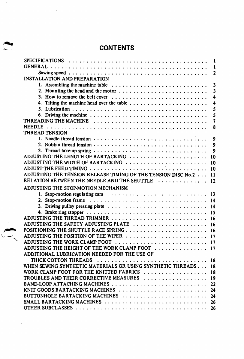
CONTENTS
SPECIFICATIONS
GENERAL
Sewing
INSTALLATION
THREADING
NEEDLE
THREAD
ADJUSTING
ADJUSTING
ADJUST
ADJUSTING
RELATION
ADJUSTING
speed
AND
1. Assembling
2.
Mounting
3.
Howtoremove
4. Tilting
5.
6. Driving
1.
2.
3.
1.
2.
the
Lubrication
the
THE
TENSION
Needle
thread
Bobbin
thread
Thread
take-up spring 9
THE
LENGTHOFBARTACKING
THE
WIDTHOFBARTACKING
THE
FEED
THE
TENSION
BETWEEN
THE
STOP-MOTION
Stop-motion
Stop-motion
PREPARATION
the
machine
the
head
machine
the
table 3
and
the
motor
belt
cover
head
over the table 4
machine 5
MACHINE
tension
tension
TIMING
THE
RELEASE
NEEDLE
TIMINGOFTHE
AND
THE
MECHANISM
SHUTTLE
TENSION
DISC
regulating cam 13
frame
3. Driving pulley pressing plate 14
4. Brake ring
ADJUSTING
ADJUSTING
POSITIONING
ADJUSTING
ADJUSTING
ADJUSTING
ADDITIONAL
THICK
WHEN
WORK
TROUBLES
BAND-LOOP
KNIT
BUTTONHOLE
SMALL
OTHER
COTTON
SEWING
CLAMP
GOODS
BARTACKING
SUBCLASSES
stopper
THE
THREAD
THE
SAFETY ADJUSTING PLATE 16
THE
THE
POSITIONOFTHE
THE
WORK
THE
HEIGHTOFTHE
LUBRICATION
SYNTHETIC
FOOT
AND
THEIR
ATTACHING
BARTACKING
BARTACKING
SHUTTLE
CLAMP
THREADS
FOR
CORRECTIVE
MACHINES
TRIMMER
RACE
FOOT
NEEDED
MATERIALS
THE
KNITTED
MACHINES
MACHINES
MACHINES
SPRING
WIPER
WORK
CLAMP
FOR
THE
OR
USING
FABRICS
MEASURES
FOOT
USE
OF
SYNTHETIC
THREADS
No.2
. . . 11
...
1
1
2
3
4
5
7
8
9
9
10
10
10
12
14
15
16
16
I?
17
17
IS
18
18
19
22
24
24
26
26
Page 4
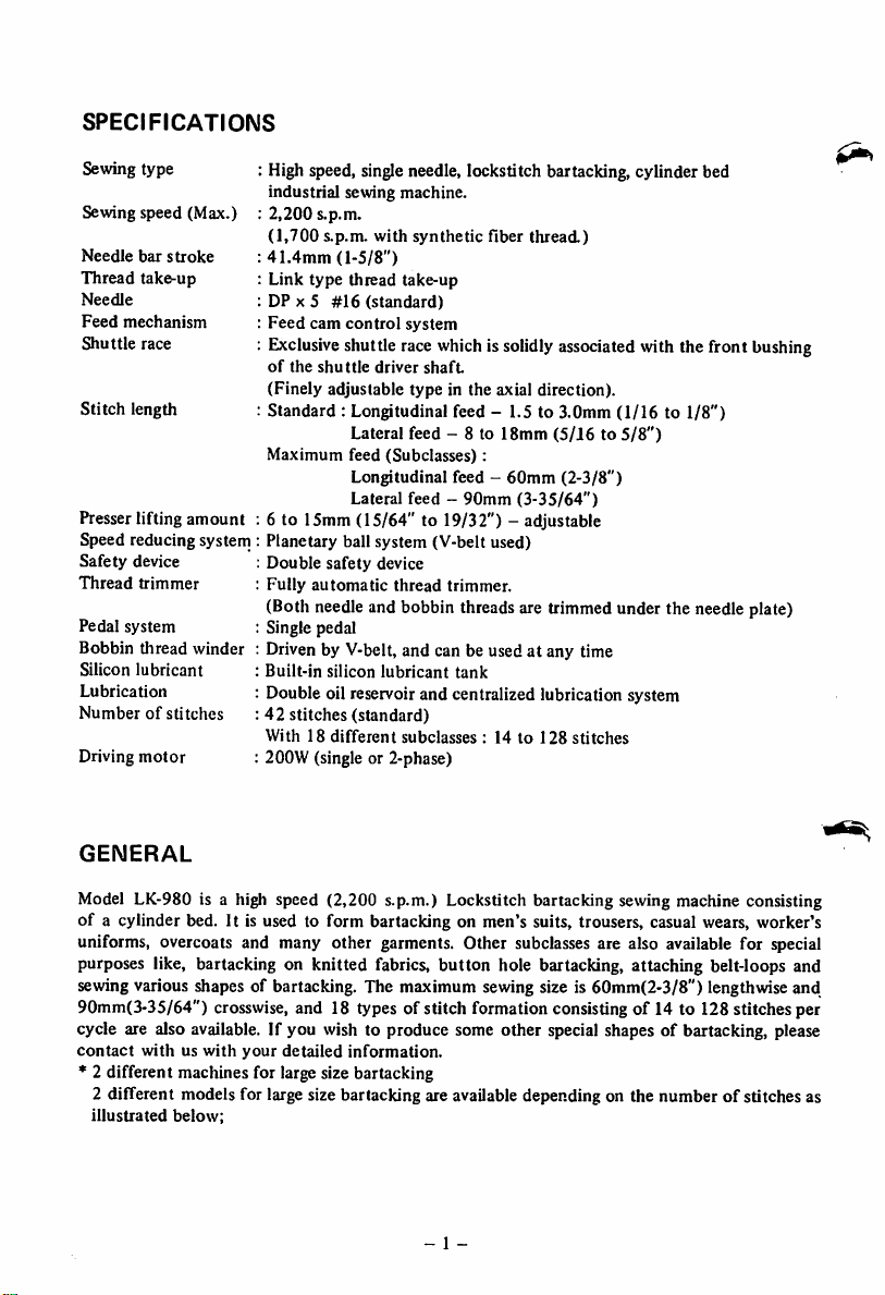
SPECIFICATIONS
Sewing
type
Sewing speed (Max.)
Needle
bar
stroke
Thread
take-up
Needle
Feed
mechanism
Shuttle
race
Stitch
length
device
trimmer
system
thread
lubricant
motor
amount
winder
Presser lifting
Speed reducing system
Safety
Thread
Pedal
Bobbin
Silicon
Lubrication
Numberofstitches
Driving
: High speed, single needle, lockstitch bartacking, cylinder bed
industrial sewing machine.
:
2,200
s.p.m.
(1,700
s.p.m.
with
:
41.4mm
: Link
: DP X 5
:
Feed
:
Exclusive
of
the
(1-5/8")
type
thread take-up
#16
(standard)
cam
control
system
shuttle race whichis solidly associated with the front bushing
shuttle
driver
synthetic
shaft
fiber
thread.)
(Finely adjustable type in the axial direction).
: Standard : Longitudinal feed - 1.5 to 3.0mm (1/16 to
Maximum feed
Lateral feed - 8 to
Longitudinal feed -
Lateral feed -
(Subclasses):
90mm
18mm
60mm
(3-35/64")
(5/J6to5/8")
(2-3/8")
1/8")
: 6 to 15mm (15/64" to 19/32") - adjustable
:
Planetary
:
Double
:
Fully
ball system (V-belt used)
safety
device
automatic
thread
trimmer.
(Both needleand bobbin threads are trimmed under the needle plate)
: Single pedal
: Driven by V-belt, and can be used at any time
:
Built-in
silicon
lubricant
tank
: Double oil reservoir and centralized lubrication system
:42stitches
With18different
(standard)
subclasses
: 14to128
stitches
: 200W (single or 2-phase)
GENERAL
Model LK-980 is a high speed (2,200 s.p.m.) Lockstitch bartacking sewing machine consisting
of a cylinder bed. It is used to form bartacking on men's suits, trousers, casual wears, worker's
uniforms, overcoats and many other garments. Other subclasses are also available for special
purposes like, bartacking on knitted fabrics, button hole bartacking, attaching belt-loops and
sewingvarious shapes of bartacking. The maximum sewing size is 60mm(2-3/8") lengthwiseand
90mm(3-35/64")
crosswise,
and 18 types of stitch formation consisting of 14 to 128 stitches per
cycle are also available. If you wish to produce some other special shapes of bartacking, please
contact
withuswith
your
detailed
information.
* 2 different machines for large size bartacking
2 different models for large size bartacking are availabledependingon the number of stitches as
illustrated
below;
- 1 -
Page 5
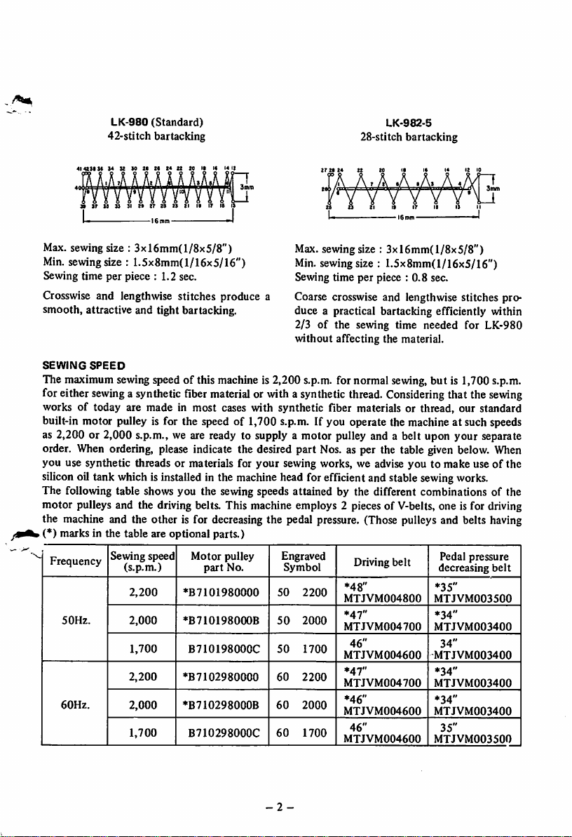
LK-980
(Standard)
42-stitch bartacking
272924
28-stitch
22
LK-982-5
bartacking
i6mtn
Max. sewing size :
Min. sewing size :
3xl6mm(l/8x5/8")
1.5x8mm(l/16x5/16")
Sewing time per piece : 1.2 sec.
Crosswise and lengthwise stitches produce a
smooth, attractive and tight bartacking.
Max. sewing size :
Min.sewingsize : 1.5x8mm(I/16x5/16")
Sewing time per piece : 0.8 sec.
Coarse crosswise and lengthwise stitches pro
duce a practical bartacking efficiently within
IGtnrn
3xl6mm(l/8x5/8")
2/3 of the sewing time needed for LK-980
without affecting the material.
SEWING
SPEED
The maximum sewing speed of this machine is 2,200 s.p.m. for normal sewing,but is 1,700 s.p.m.
for either
sewing
a synthetic fibermaterial or with a syntheticthread.
Considering
that the
sewing
works of today are made in most cases with synthetic fiber materials or thread, our standard
built-in motor pulley is for the speed of 1,700 s.p.m. If you operate the machine at such speeds
as 2,200 or 2,000 s.p.m., we are ready to supply a motor pulley and a belt upon your separate
When
order.
ordering, please indicate the desired part Nos. as per the table given below.
you use synthetic threads or materials for
your
sewing works, we advise you to make useofthe
When
siliconoil tank whichisinstalledin the machinehead for efficient and stable sewingworks.
The following table shows you the sewing speeds attained by the different combinations of the
motor pulleys and the driving belts. This machine employs 2 pieces of V-belts, one is for driving
the machine and the other is for decreasingthe pedal pressure. (Those pulleys and belts having
.(*) marks in the table are optional parts.)
Frequency
50Hz.
60Hz.
Sewing speed
(s.p.m.)
2,200
2,000
1,700
2,200
2,000
1,700
Motor
pulley
part
No.
♦B7101980000
»B7101980(K)B
B710198000C
♦B7102980000
♦B710298000B
B710298000C
Engraved
50
50
50
60
60
60
Symbol
2200
2000
1700
2200
2000
1700
Driving
belt
*48"
MTJVM004800
*47"
MTJVM004700
46"
MTJVM004600
*47"
MTJVM004700
*46"
MTJVM004600
46"
MTJVM004600
Pedal pressure
decreasing
*35"
MTJVM003500
*34"
MTJVM003400
34"
MTJVM003400
*34"
MTJVM003400
*34"
MTJVM003400
35"
MTJVM003500
belt
-2-
Page 6
INSTALLATION
AND
PREPARATION
1. Assembling
Paste
the
installation
Make
the installation holes with spot
the
attached
holes.
machine table
pattern
paperonthe
surfaceoftable
facing
first, and then attach the
installing base,spoolholderbase,headsupport and tension
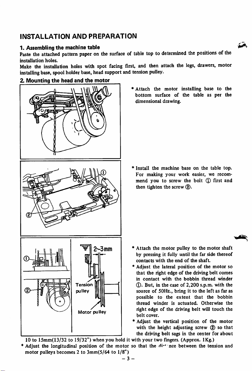
2.
Mounting
the
head
and
the
motor
* Attach the
bottom
dimensional drawing.
* Install
For
mend
then tighten the screw@.
toptodetermined
pulley.
motor
surface
the
making
you
machine
to screw the
installing base to the
of
the
base
your
work
the
positionsofthe
legs,
drawers,
table as
on the table
easier, we recom
bolt
® first and
motor
per
the
top.
z-^omm
* Attach the
motor
pulley to the
motor
by pressing it fully until the far side thereof
Tension
pulley
Motor
pulley
contacts
* Adjust
that
in
®.
sourceof50Hz., bring it to the
possible
thread
right edge of the driving
belt
* Adjust
with
the
the
endofthe
lateral position of
shaft.
the
the right edge of the driving
contact
with
the
bobbin
thread
But, in the case of 2,200 s.p.m. with the
left
to
the
extent
that
winderisactuated.
cover.
the
vertical
positionofthe
belt
the
Otherwise
will
with the height adjusting screw (D so
the driving belt sags in the center for
10 to 15mm(13/32 to 19/32") when you hold it with your two fingers. (Approx. IKg.)
Adjust the longitudinal positionofthe
motorsothat
the Hi-' nee between the tension and
motor pulleys becomes 2 to 3mm(5/64 to 1/8")
-
3-
motor
belt
as far as
touch
shaft
so
comes
winder
bobbin
the
the
motor
that
about
Page 7
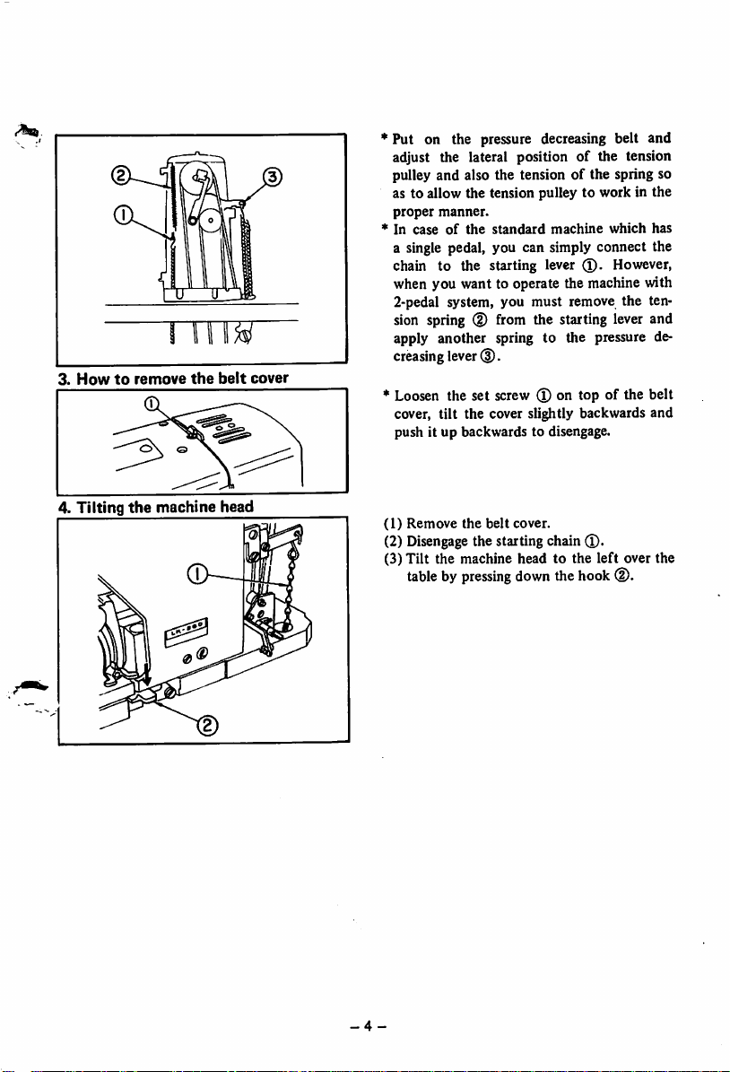
3.
Howtoremove
4.
Tilting
the
the
machine
belt
head
cover
* Put on the pressure decreasing belt and
adjust the lateral position of the tension
pulley and also the tension of the spring so
as to allow the tension pulley to work in the
proper
manner.
* In
caseofthe
standard
machine
which
has
a single pedal, you can simply connect the
chain to the starting lever However,
when you want to operate the machine with
2-pedal system, you must remove the ten
sion spring (D from the starting lever and
apply another spring to the pressure de
creasing
lever
d).
* Loosen the set screw (D on top of the belt
cover,
tilt
the cover slightly backwards and
push it up backwards to disengage.
(1)
Remove
(2)
Disengage
(3)
Tilt
tablebypressing
the
belt
cover.
the starting chain d).
the
machine
headtothe
down
thehook(D.
left
over
the
-4
-
Page 8
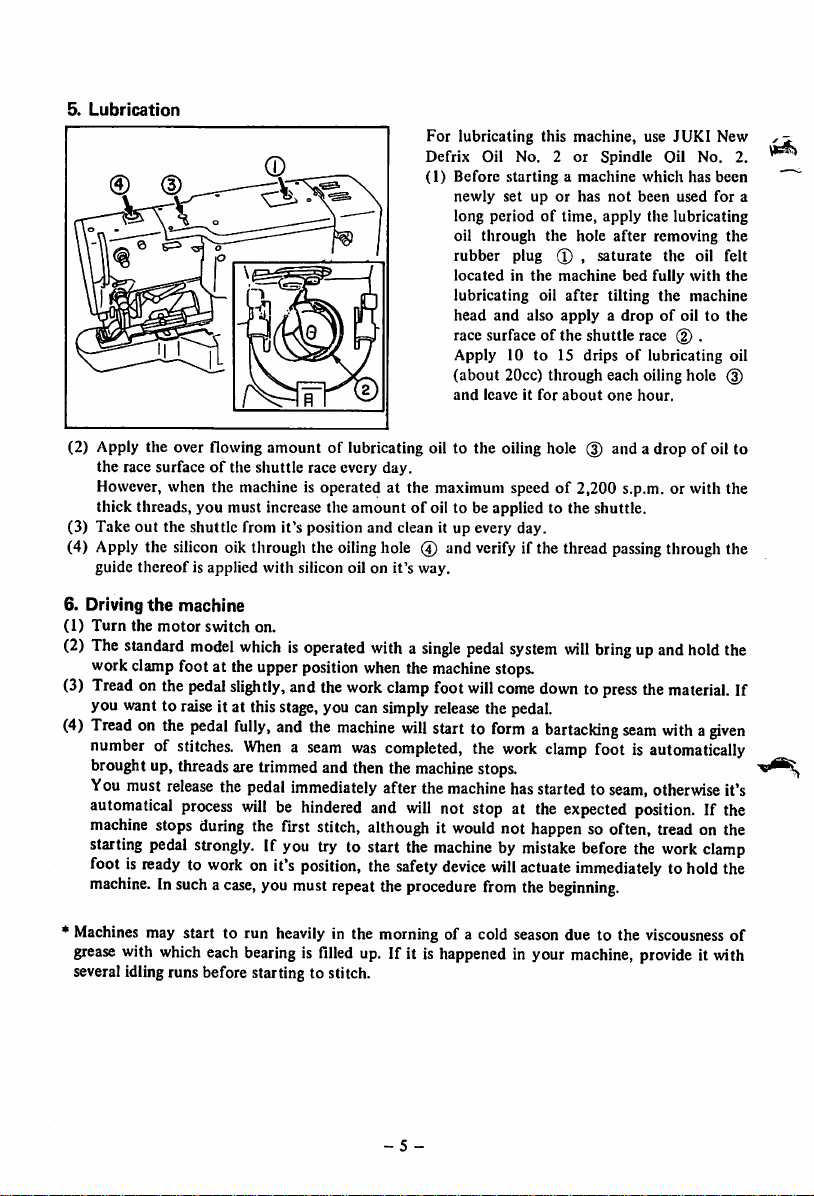
5.
Lubrication
For
lubricating this
Defrix
Oil No. 2
(1) Before
(2) Apply the over flowing amount of lubricating oil to the oiling hole (5) and a drop of oil to
the
race surfaceofthe
However, when the machine is operated at the maximum speed of 2,200 s.p.m. or with the
thick threads, you must increase the
out
(3) Take
(4) Apply the silicon oik through the oilinghole 0 and verify if the thread passingthrough the
guide
the shuttle from it's position and clean it up every day.
thereof
is applied
shuttle
with
race every
silicon oil on
day.
amountofoil to be applied to the shuttle.
it's
way.
startingamachine
newly
set uporhas
long
periodoftime,
through
oil
rubber
locatedinthe
lubricating oil
head
and
race
surfaceofthe
Apply
10 to 15 dripsoflubricating oil
(about
20cc)
and
leaveitfor
machine,
or
Spindle
apply
the
plug
hole
(l) ,
saturate
machine
after
also
applyadropofoil to
shuttle
through
about
use
which has
not
been
the lubricating
after
bed
fully
tilting
race
each
oiling
one
hour.
JUKI
Oil No. 2.
used
removing
the
oil
with
the
machine
(2) .
hole
New
been
for
the
felt
the
the
(3)
a
6. Driving
(1)
(2)
(3)
(^)
*
Machines
grease
several idling runs before starting to stitch.
the
machine
Turn
the
motor
switch
The
standard
work
Tread
you want to raise it at this stage, you cansimply
Treadonthe
model
clamp
footat theupper
on the
pedal
pedal
numberofstitches.
broughtup, threadsare
Youmust
automatical
machine
starting
foot is
release
process
stops
pedal
readytowork
machine.Insuchacase,
may start to run heavily in the morning of a cold season due to the viscousness of
with
which
on.
whichisoperated
slightly,
andthe
fully,
and
Whenaseam
trimmed
the
pedal
immediately
willbehindered
during
the first stitch,
strongly.Ifyou
on it's
you
must
each
bearingisfilled
position
work
the
machine
and then the
try to start the
position,
repeat
withasingle
when
the
machine
clamp
foot
release
will
was
starttoformabartacking
completed,
machine
after the
and
machine
will
not stop at the
althoughitwould
machinebymistake
the
safety
the
up. If it is
- 5 -
device
procedure
happened
pedal
stops.
will
come
the pedal.
the
stops.
not
will
from
system
will
downtopress
work
clamp
hasstarted to
expected
happen
actuate
the
beginning.
in your
machine,
bringupand
seam
foot is
seam,
hold
the
material.
withagiven
automatically
otherwise
position.
If the
so often, tread on the
before
the
work
clamp
immediatelytohold
provide
it with
the
If
it's
the
Page 9
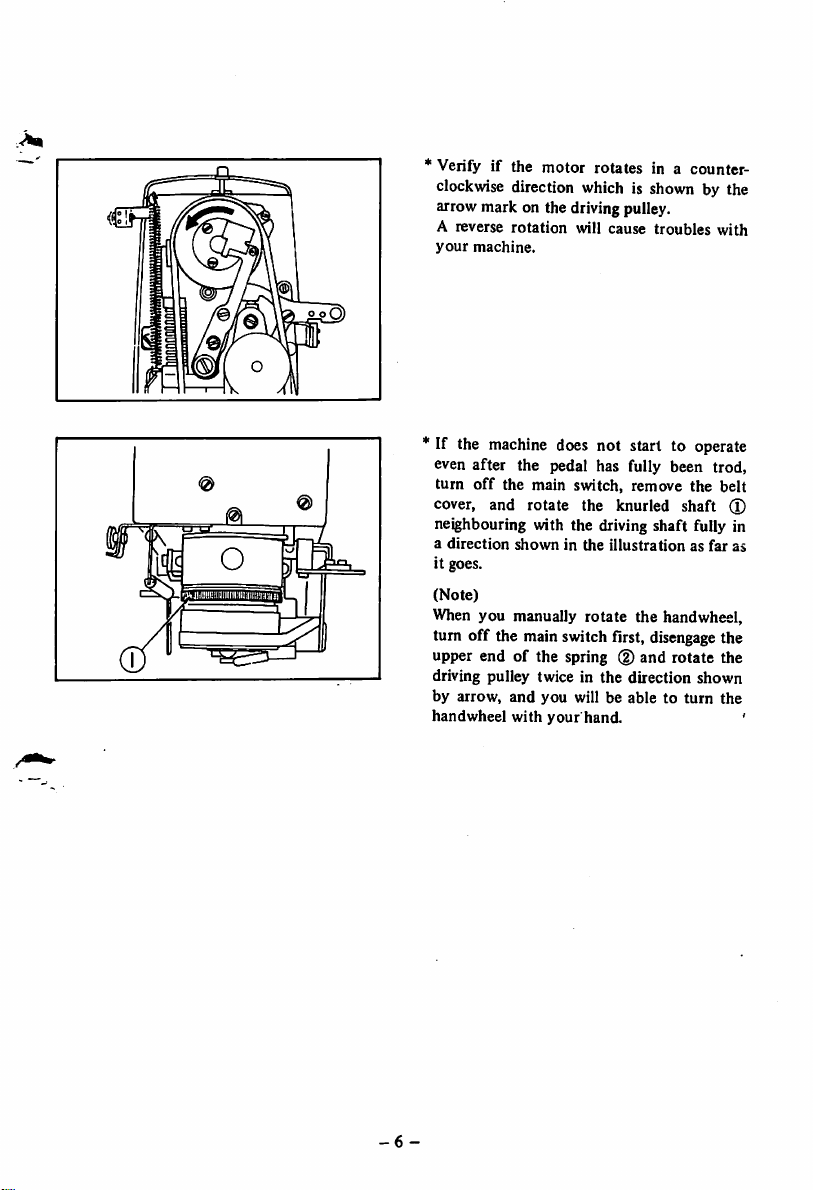
* Verify if the motor rotates in a counter
clockwise
direction
which
is shown by the
arrow mark on the driving pulley.
A reverse
your
machine.
rotation
will cause troubles
with
"If the
machine
does not start to operate
even after the pedal has fully been trod,
turn
off
cover, and
the main switch, remove
rotate
the knurled shaft
the
neighbouring with the driving shaft fully in
a
direction
it goes.
(Note)
showninthe
illustrationasfar
When you manually rotate the handwheel,
turn off the main switch first,
disengage
upper end of the spring (2)and rotate the
driving pulley twice in the direction shown
by arrow,
handwheel
and
with
you
your
will be
hand.
abletoturn
belt
(X)
as
the
the
'
-6-
Page 10
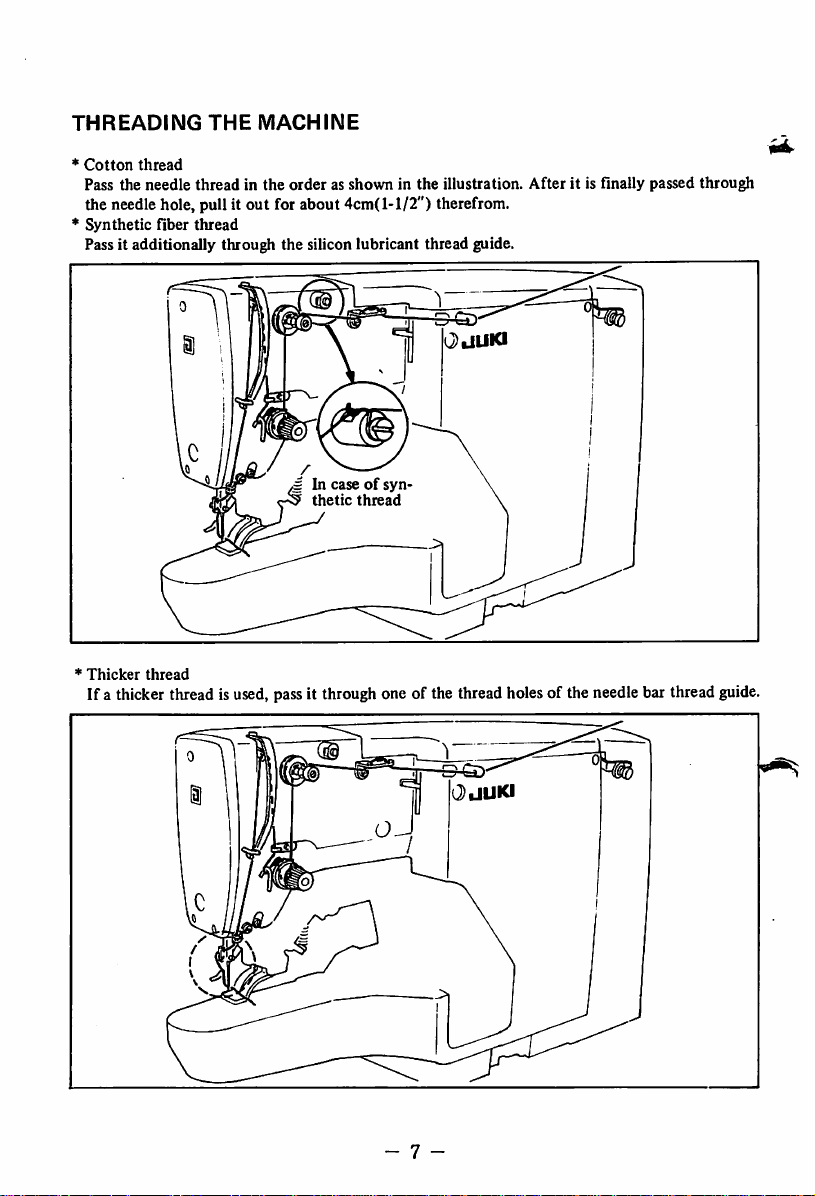
THREADING
*
Cotton
thread
Pass the
needle
THE
MACHINE
threadinthe
orderasshowninthe
illustration.
After
it is finally passed
the needlehole, pull it out for about 4cm(1-1/2") therefrom.
*
Synthetic
fiber
thread
Passit additionally through the silicon lubricant thread guide.
OldUKI
g In
caseofsyn
thetic
thread
*
Thicker
thread
If a thicker thread is used, passit throughone of the thread holesof the needlebar thread
through
guide.
- 7 -
Page 11

NEEDLE
iitnumi
*
Needles
Very light weight
material
Synthetic
material
Medium heavy weight
material
Heavy weight
material
(Note)
and
Sewing-cloth
fiber
For
sewing a very
material
> 1
#11
#14
SUPER
#16
#18
thick
material
lor?
Needle
(DPx5)
(DP
X 5
needle)
(DPX5)
(DP
X 5)
like denim, a subclass
*
Howtoattach
o DP X 5, No. 16 is
machine.
needle clamping
Insert
the
needle
the
standard
the
hole
needle
needle
fully
on the needle bar by
for
into
facing the long groove thereof towards you
and clamp
the
needle with a screw,
o If the needle thread forms such faulty
stitchesasshown
maybeeffectivetosolve
in the
above
illustration, it
themtoturn
needle slightly to the left,
o When you are going to sew a synthetic fiber
material
a
Needle hole guide
D2426-282-C00
B2426-280-000
B2426-280-000
B
2426-280-000
SUPER
(standard)
(standard)
(standard)
withasynthetic
needle.
Made-up goods
Knittedortricot
Men's
Men's
Working wears
overcoats
machine
LK-984-50 is available.
fiber thread,
and
ladies'
and
ladies'
and
attach
wears
suits
suits
this
the
the
• Winding
the
bobbin
@
thread
spindle.
(2)
Pass
around
direction
(3)
Push
the
starttowind.
wound
(4)
Normally
of
it's
(5)Ifthe
the
the
threadasillustrated
the
bobbin
shownbythe
the
bobbin
bobbin,
and
up, it will
the
capacity.
bobbiniswound
nut
(I) and turn the bobbin adjusting
screw (D clockwise.
(6)Ifthe
(7) Do
the
bobbin
the
not
threadisnot
bobbin,
winder
not
forget to
machine
attach
adjust
before
the
be guided properly to the
wheel and
wind
the
the
bobbin.
* Use genuine JUKI bobbin case and bobbin, or bobbin may idle or slip
-
8-
several
arrow
winder
trip
the
bobbin
As
soonasthe
automatically
bobbiniswound
too
wound
the
positionofthe
base
(3).
attach
the
driving it. If
belt
cover,
the
bobbin
mechanism
outofbobbin case.
and
wind
turnsinthe
mark.
latch
towards
thread
bobbin
stop.
about
much,
loosen
evenly
around
belt
cover to
you
belt
will
winder
may
fail to
it
will
is
80%
do
not
Page 12

THREAD
TENSION
No.1thiead
disc
\
Arm
thiead
guide
A
.Thread
No.2thread
tension
spring
take-up
disc
L
tension
1.
Needle
thread
tension
(1)
Thread
o This is mainly used
tension disc No. 1
of
the
thread
for
leftonthe
adjusting
needle
the
after
length
ming.
The
needle
thread
o
tension varies
depending
on its quality. Adjust the length of needle
thread
whichisleftonthe
trimmed by turning the tension disc
that
the
thread
but
can
does
not
becomesasshort
not
slip
outofthe needle.
get a satisfactory result from this
needle
afteritis
No.l
as possible
(If
adjustment, try to adjust it with the tension
disc
No.
2 as
(2)
o
This
needle
creases
2.
o Pull
on
Thread
disc
Bobbin
the
the
described
tension
No.2isused
thread
the
tension.
thread
bobbin
bobbin
disc
tension.
tension
thread
case for
later.)
No.2
about
for
adjusting
Oockwise
through
2.5cm(l")
turn
the
put the bobbin case into the shuttle race
ring.
o
The
bobbin
thread
by
turning
Clockwise
counterclockwise
the thread
turn
tension can be
tension
will
increase
turn
will
decrease
screw
the
adjusted
d).
tension
it.
trim
so
you
the
in
hole
and
and
Thread
spring
3.
Thread
The
normal
take-up
stroke
spring
of
the
thread take-up
spring is 6 to 8mm(15/64 to 5/16") and the
tensionatthe
oToadjust
(X)
and
starting
point
the
stroke,
rotate
the tension controller as
is 30to50g.
loosen
sembly to left or right,
o To
adjust
the
tension,
insert
the
screw
driver
into
the
small
tension
creaseorcounterclockwise
tension.
o
Synthetic
needle, if the
stroke
must
lessen
-9
-
post
and
turnitclockwise to in
flber
thread
thread
and
high tension. In this case,
the
tensionofthe
groove on
to
may
slip
take-up spring has large
spring.
the
set
bladeofa
decrease
outofthe
screw
the
the
you
Page 13

ADJUSTING
THE
LENGTH
OF
BARTACKING
Loosen the wing nut 0 to clamp the cross
wise feed regulator and move it downwards
for producing longer bartackings or upwards
for
shorter
after
bartackings.
adjustment
Ti^ten
the wing
nut
ADJUSTING
ADJUSTING
t ^
7—IOhuh
THE
THE
kfJli
Ul 1
WIDTH
FEED
f
V
/f
OF
BARTACKING
TIMING
1/
Loosen the lock
nut
0 on the feed regulator
and turn the adjusting knob ® counterclock
wise
for producing wider bartackings or clock
wise for narrow bartackings. Tighten the lock
nut 0 securely after
o A
cloth
feed
when
the
height of 7 to 10mm(9/32 to 25/64") above
the
top
o
o If
surfaceofthe
Better
thread
height is closer to 7mm(9/32").
loose
stitchisformed
thread,
it is
changing the said height closer to 10mm
(25/64").
adjustment
motion
mustbecompleted
needle
has
come
downtothe
throat
with
plate,
synthetic
this
tensionisobtainedasthe
effectivetosolve
said
fiber
trouble
by
-
10-
Page 14

ADJUSTING
DISC
No.2
Needle
thread
Too
long
Length is
form
Too
Thread
the
not
short
is snapped on
way
and
jumps
uni
THE
up
TENSION
Tension
release
Pushitup
Push it up
Pushitdown
Pushitdown
RELEASE
lever
TIMING
OF
THE
TENSION
(1) Position of the tension release latch trip
ping
segment
Adjust the position of the tension release
latch tripping segment (f) so that the
pointed end of the tension
release
latch
stays on top of (2) at the time of stop
motion.
(2) If the tension release timing at the tension
disc No.2 is incorrect, the length of thread
leftonthe
too
the
needle
short
or the thread may slip
needleatthe
startofbartacking.
after
trimming may be
out
The
vertical position of the tension release
lever (D must be properly adjusted by
loosening
tension
moment
the
hinge
disc
No.2isreleased
when the
screw
® so that the
top
endofthe thread
at
the
take-up leverhas gone up to coincide with
the engraved mark (5)after completion of
the
last
stitchofa bartacking.
Adjust the height of the tension release
lever in the following way in order to
obtain an ideal length of remaining thread
at
the
needle
after
trimming;
of
* Adjust the position of the pointedend of the
tension
release
latch ® by meansof the adjusting
screw(j) so that the said pointed end of ® is brought closerto but not into contact withthe
surface of feed cam ® during running.
-11-
Page 15

RELATION
Height of . Position of
«edleb^
BETWEEN
KbSl
ing
Upper indi
^
eating
Lower
gating
Needle
qm
line
indi
tin^
bar
THE
sewing
h^k
i>1
kCt
0.3~0.5
NEEDLE
AND
THE
SHUTTLE
Adjust the positionsofthe needle and the
shuttle in the following way; Switch
machine,
tread
on the
starting
pedal
the driving pulley manually until
bar
comes
down
to its
bottom
dead
* Howtoadjust
(1) Loosen
the
the
heightofthe
needle bar
clamp
and
the
point.
needle
screw.
off
rotate
needle
the
bar
(2) Bring the upper marking line on the
needle
bottom
bushing.
(3)
Tighten
*
Howtoadjust
bartothe
surface
the
same
of
needle bar
the
positionofthe
levelasthatofthe
the
needle
clamp
screw.
shuttle
bar
lower
(1) Rotate the driving pulley further until the
lower marking line on
the
agrees to
bushing.
bottom
the
needle bar
surfaceofthe
lower
(2) At this stage, loosen the shuttle driver
clamp
screw,
adjust
the
positionofthe
shuttle
point
so as to
meet
with
the
center
line of the needle and tighten the clamp
screw.
No
clearance
the needle
driver,
driver
to
because
actuates
prevent
and
it from being
(3) Loosen the shuttle race clamp screw
the
to
front
the
receive
mustbeleft
edgeofthe
front
edgeofthe
the
bent.
between
needle
said
and
©.
(4) Adjust the longitudinal position of the
shuttle
racebyturning
the
shuttle
race
adjusting shaft (D so that the clearance
between
becomes
0.00394").
(5) Tighten the clamp screw
the
0.05
needle
to
and
0.1mm
the
(T).
shuttle
(0.00197
point
to
*
Howtotake
out
the
shuttle
Disengage a pair of shuttle race latches ®
towards
them
and
Do it carefully
floor.
-12-
towards
shuttle
left
and
right respectively by pulling
you,
and
the
are
taken
nottodrop
out
shuttle
from
the
race
the
ring
positions.
shuttleonthe
Page 16

ADJUSTING
Stop-motion
lever
tension
spring
THE
STOP-MOTION
Driving-pulley
Stop-motion
cam
MECHANISM
1.
Stop-motion
While
the
wheel,
the
the
starting pedal. Disconnect the stop-
motion
anchor
and
rotating the driving pulley (D 2 to 3 turns
in
the
normal
Tread
on the pedal for
so astolet
cam coincide with the top edge of the
stop-motion
regulating
machineisoperatedbythe
safety
device
lever
tension
lower
the
direction.
cam
workstolock
spring (T)
work
clamp
starting
"A"
pointofthe
hook.
hand-
up
from
its
foot
by
the
machine
stop-motion
Stop-motion
Stop-motion notch
screw
Stop-motion
hook
Stop-motion
roller
regulating cam
By keeping this
motion
regulating cam idly in the direction
shown
by the
point
"B"
with the
camatthis
-
13
condition,
arrow
in figure
of the cam comes
stop-motion
position
roller and fix the
with
the
turn
cam
the stop-
until
into
set
the
contact
screw.
Page 17

1-1.
Stop-motion cam
Stop-motion
The timing to let the roller
the
stop-motion
cam
notch
after
drop
the last
and rest in
stitch
sewn is determined by the positionofthe
2nd
/ ^
screw. / -—s.
1st
screw
stop-motion
Provide the stop-motion notch with a proper
position by moving it up or down, according
to
the
notch.
sewing speeds as listed below, when
the last stitch is sewn and the top edge of
the
(Note)
Stop-motion
hook
In caseof1,700
s.p.m.
stop-motion
motion
cam.
Position of
At
1,700
At
2,000
At
2,200
s.p.m.
s.p.m. Between the 1st and the
s.p.m.
the
stop-motion
hook
touches the stop-
hook
Centerofthe
2nd
screws.
Centerofthe
2nd
screw.
1st screw.
The degreeofstop-motion shock depends also on the position of the stop-motion notch.
If the sewing machine carries an excessive rotational torque to reduce its sewing speed especially
in a cold season, shift the
the
counteraction.
notch
position counterclockwise along the circumference to increase
2.
Stop-motion
frame
Adjust the position of the roller shaft (f) on
No.2marking
No.1marking
line
line
the regulating cam so
surface of the brake ring and the 2nd
marking
coincide
speed
line on the stop-motion hook (D
with
running.
each
that
the circumferential
otheratthe
timeoflow-
3. Driving pulley pressing plate
At the
moment
the
stop-motion
circumferential
the driving clutch must be engaged to drive
the
machine.
ing the position of the driving pulley pressing
plate (J) by means of the adjusting screw (6).
Use a
spanner
for this adjustment. Tighten the nut in such a
wayasto
20 mm
tightened. Please note
runs
too
runs
too
heavier.
(Note)
Ensure always
and
brake
-
14
-
when
the
hook
surfaceofthe
Obtain
such
(9 x 10) in
turn
the
(25/32")
endofthe
after
fast, it will make
slow, it will
cork
that
the slow speed
ring ®
make
1st
marking
line
(5) coincides with
brake
ring (4),
functionbyadjust
the
accessory
spanner
it has been
that,
much
the
don't
further
properly
if the machine
noise and if it
starting
cork
ring (D
rotate during
box
pedal
is
on
the
Page 18

operationofthe driving pulley (§) while the
machine is suspended.
since it causes wearing
tion gear if the slow speed cork ring (g) and
Readjust
accidentsofthe
the
screw (6)
reduc
brake cork ring @ are rotating.
4.
Brake
ring
stopper
Adjust the brake ring stopper © so that the
0.3mm
brake cylinder
tionby0.3mm
run.
(Q)
moves in the arrow direc
when
the
machine
starts
Make sure that the screw (g) is firmly clamp
ing the brake ring stopper
(Note)
®.
For disassemblyand assembly of the slow speed cork ring (5) to lubricate greasereplace should be
done in the following order:
1.
Remove
the
driving
pulley
pressing
plate
(T)
and the
driving
pulley
(g)
and
remove
the C ring
(D with the tool (§) and the slow speed cork ring (5) is removed.
2.
Reinstall
after
couple
the
applying
the
slow speed
previously
grease,
usedclutch spring bracket
give
grease
ring
to the end
and
main
shaft
cork
(small)
(S)
surface
of the mainshaft thrust
thrust
washer
to the newslowspeedcork ring
washer
with
the
main
shaft.
® and
3. Replacealwaysthe C ring (D with new one and install it in the followingway:
1)
Widen
the C ring open enough to be inserted in the main shaft by means of a tool and place
if from the position
positionofthe C ring during operationofthe machine).
(g)
to (g). (If the C ring is widened too largebe careful to avoidoff-
2) Push the C ring from position (g) to the groove © of the main shaft in the direction of
arrow
3)
Asertain
(<-)byusing 2
whether the C ring fits into the
screw
drivers.
groove
© by
pulling
hard the slowspeed cork
ring (D by hand towards the directionofarrow (-»).
to
/i-C-Q
Page 19

ADJUSTING
THE
®(S)
THREAD
TRIMMER
At
the
timeofstop-motion,
between the rear end of the movingknife (l)
and the edge of the needle hole located on the
needle
holeguidemustbe 1.5mm(l/16").
Loosen
the
screw (3)
ing the moving knife.
and
adjust
the
clearance
it by position
ADJUSTING
ADJUSTING
Whilethe presser foot is raised at the time of
stop motion, move the safety adjusting plate
® in the arrow direction until it comes in
contact
with the safety plate (2)
_^,^^learance
^ (1/64") when the presser foot is brought
down. Fix the safety adjusting plate at such
a position.
between
THE
PLATE
0.3mtn
them
SAFETY
becomes
and
also the
0.3mm
POSITIONING
RACE
SPRING
THE
SHUTTLE
5
a
Lateral
position:
The center line of the groove must coin
cide
with
the
needle
center.
Longitudinal position:
The corner (g) must coincide with the rear
endofthe
needle.
—16—
Page 20

ADJUSTING
THE
POSITION
0
OF
THE
WIPER
* When you adjust
the
heightofthe
loosen the screw ® on the wiper installing-
plate
and adjust
the
heightofthe
wiper,
wiper
installing plate vertically along the adjust
able
screw
hole.
*
The
o
clearance
thatofthe
when
centerofthe
To
check
shaft
(page. 13) in
the
needle
dead
point
* During this adjustment, you
not
to allow it to hit either the work clamp
footorthe
between
needle
the
wiper has swung
needle.
this
clearance,
has
the tipofwiper and
mustbel.Smm(l/16")
rotate
the
normal
come
downtothe
at the time of stop-motion.
needle.
down
the
direction
must
be careful
to the
knurled
until
bottom
ADJUSTING
ADJUSTING
THE
WORK
26th
stitch
'
(42-stitch
largebartack-^
in^
18th
stitch
(28-stitch
large bartack-
in^
THE
HEIGHT
CLAMP
OF
FOOT
* In case of the 42-stitch bartacking: the 26th
stitch
mustbelocatedonthe-
work
clamp
foot
and
right wings).
(on the joining lineofleft
* In case of the 28-stitch bartacking; the 18th
stitch
work
mustbelocated
clamp
foot (on the
on
and right wings)
* Adjust it by moving the roller shaft
the
THE
direction
fllustration.
WORK
CLAMP
shownbyarrow
FOOT
The adjustment in the height of work clamp
foot ranges from 6mm( 15/64") to 15mm
(19/32") depending on the thickness of
materials.
centerofthe
the
centerofthe
joining
lineofleft
(T)
markonthe
in
17
-
Page 21

ADDITIONAL
COTTON
When a
thicker
not
enough to form well tightened stitches.
LUBRICATION
THREADS
thread
than
No.30orNo.20
NEEDED
are used, the
FOR
lubrication
THE
USE
to the
OF
shuttle
THICK
race
may
be
In such a case, we recommend you to lubricate the shuttle race manually 3 or 4 times a day in
ordertolessen
the
rotational
load from the
shuttle
andtoproduceabetter
sewing condition.
WHEN
THE
USING
SYNTHETIC
SYNTHETIC
MATERIALS
THREADS
OR
SEWING
We advise you to operate the machine in the following way when you use synthetic threads or
sew
chemicalorsynthetic
1) Replace the motor pulley with a special pulley for sewing synthetic materials.
sewing speed is 1,700 s.p.m.)
2) Use
the
silicon
lubricant
materials;
tank
additionally.
(Maximum,
Refer to the paragraph under the "Threading the machine".
3) Use a SUPER needle for
4) Lessen the
WORK
stroke
CLAMP
synthetic
from the thread take-up spring.
FOOT
FOR
fiber thread.
THE
KNITTED
FABRICS
The following optional work clamp feet are available for bartacking on the very light weight
materials, light weight materials or knitted fabrics;
Workclamp foot for the knitted fabrics (Right) B2551-280-00B
Work clamp foot for the knitted fabrics (Left) B2552-280-00B
Feed plate for the knitted fabrics B2519-280-008
-
18
Page 22

TROUBLES
No.
Troubles
1.
Needle
slips
outatthe
startofsewing.
2.
Thread
is
snapped
often
or
synthetic
thread
is
ravelling.
3.
Synthetic
threadisbrok
enorlorms
loose
stitches
at
the
start
sewing.
thread
very
AND
THEIR
Some
1.
the
2.
Needle
shortonthe
CORRECTIONS
Causes
stitches
start
of stitching.
threadisleft
thread trimming.
3.
Bobbin
threadistoo
4. Material is rippled.
5.
Tension
disc
high tension.
1.
Shuttleorshuttle
spring
has
surface.
scratchedonit's
2. Shuttle race spring has a
scratchonthe
3. Needle hole guide is bruised.
4. Needle hits the work clamp
foot.
5.
Mbrous
dust
grooveofshuttle
6.
Clearance
shuttle
shuttleistoo
7.
Thread
small.
between
driver
take-up
8. Stroke of the thread take-up
spring is too big.
1.
Duetothe
heatoffriction.
2. Timing of feed is
of
correct.
are
skipped
too
needle
after
short.
No.1has
driver
surface.
staysinthe
race.
the
and
the
small.
strokeistoo
not
Corrections
at
Adjust
the
needle
0.1mm
Referto"Needle
a
"Adjusting the tension release timing
of
Lessen
Increase
counter
clearance
and
the
shuttleto0.05mm
(0.00197"to0.039").
the
tension
disc
the
bobbin
the
clearance
knife
and
guide.
Refer to "Work clamp foot for the
knitted
fabrics".
too
Increase
the
strokeoftlic
take-up spring or decrease the tension
from
the
tension
disc
Poli.sh tho.se surfaces by meansofoil
stonesorbuffs.
Remove such scratch by buffing or
replace
it.
Polish it up with buffs, or replace it.
Refer to "Adjusting the work clamp
foot".
Take
out
the
shuttle
dust
from
the
shuttle
Bend
the
shuttle
driver
the clearance to 0.3 to
to
1/32")
Move the arm thread guide A to the
left.
Referto"Needle
Lessen
the
stroke.
Refer to "when sewing synthetic
materials or using synthetic threads."
Refer to "Adjusting the feed timing."
between
thread
No.2".
thread
between
the
needle
No.
and
race.
so astomake
0.5mm(l/64"
thread
the
tension"
tension.
hole
thread
1.
remove
tension."
the
and
any
to
,
19
-
Page 23

No.
Troubles
4.
Needleisbrok
en frequently.
5.
Threads
not
trimmed.
are
Causes
1. Needle is
2. Needle
foot.
hits
not
straight.
the
3. Timingoffeed is
correct
work
not
clamp
Replace
Refer to
foot.
Refer to "Adjusting the feed timing".
Corrections
the
needle.
"Adjusting
the
work
4. Wiper hooks the needle. Adjust the heightofwiper.
5.
Needleistoo
6.
Positionofthe
driverisnot
fine.
shuttle
correct.
1. Height of the counter knife
is
not
correct.
2.
Bladeofcounter
not
sharp.
3.
Differenceoflevel
the
needle
the
counter
knife
hole
guide
knifeisnot
between
and
Select a suitable needle according
the
typeofmaterial
Referto"Motionsofthe
the
shuttle".
Raise the blade edgeofcounter
0.5mm(0.0197")
level
is
Sharpen
the
knife.
Adjust it to 0.1 to 0.15mm(0.0039"
to
0.0059")
from the installation
enough.
4. Positionofthe moving knife
is
not
correct.
5.
Positionofthe
spring is
6.
The
last
not
stitch
shuttle
correct.
skips.
race
Refer to
trimmer."
Refer to "positioning the shuttle race
spring".
Referto"motionsofthe
the
shuttle
"Adjusting
race."
the
thread
needle
needle
clamp
to
and
knife by
and
Thread
ing length is
not
adequate.
6.
Stitches
very
trimm
often.
skip
1. Tension release timing
tension
disc
shuttle
and
No.2isnot
needle
are
not
between
the
shuttleistoo
properly
the
not
correct.
1.
Motionsofthe
the
synchronized.
2.
Clearance
needle
much.
3. Timingoffeed is
of
and
correct.
-20-
Refer to "Adjusting the tension release
timing of the tension disc No.2".
Referto"Relation
needle
and
Refertothe
the
shuttle
above.
betweenofthe
race."
Refer to "Adjusting the feed timing."
Page 24

No.
Troubles
7.
Needle
thread
comes
out
the
bottom
surfaceofthe
material.
8. Work clamp
foot
does
go
up.
9.
Machine
not
start.
not
does
Causes
4. Needle is
not
S. Material is rippled.
6. Bobbin thread is
1.
Needle
of
2.
thread
enough.
Tension
release
is
outoffunction.
3. Thread length
ming is
too
1. Positionofthe stop-motion
is
not
correct
2.
The
forceofinertiaisnot
enough.
3. Safety adjusting plate is
positioned
incorrectly.
4. Motor is running in the
reverse
direction.
5.
Motor
does
1.
The
forceofinertiaisnot
enough.
2. Clutch slips at the high
speed
operation.
3. Starting pedal is
early.
4. Positionofthe safety
adjusting plate is
5. Position of the stop-motion
hookisnot
correct.
6. Push down slide plate does
not
return
smoothly.
straight.
too
tensionisnot
mechanism
after
long.
not
run.
trod
not
tight.
trim
too
correct.
Correction
Replace the needle.
Refer to "Work clamp foot for the
knitted
fabric."
Lessen the bobbin thread tension. Keep
the
counter
knife
away
from
the
mating surface of the needle hole guide.
Adjust
the
Verifyifthe
tensionofthe
tension
release
needle
mechanism
thread.
is working during operation.
Refer to "Adjusting the tension release
timingofthe tension disc
Trytoidleitonce.
No.2".
Movethe stop-motion regulating cam
slightlytoit's
rotational
direction.
Refer to "Adjusting the safety adjust
ing plate".
Correct
it.
(normal
directionisshown
by arrow mark on the pulley.)
Motor must keep running continuously.
Movethe stop-motion regulating cam
slightly to
it's
rotational direction.
Refer to "Driving pulley pressing
plate".
Starting
pedal
work
clamp
mustbetrod
foot
has
come
after
the
downtoit's
position.
Refer to "Adjusting the safety adjusting
plate".
Refer to "Adjusting the stop-motion
mechanism."
Correct
it.
-21
Page 25

No.
10.
Stop-motion
makes
much
Troubles
too
noise.
Causes
1.
The
forceofinertiaistoo
great
2. Driving belt is
too
tight.
Correction
Move the stop-motion regulating cam
slightly in
rotation.
Adjust
it's
reverse
the
positionofthe
direction
motor
of
so
that the driving belt has proper tight
ness. (The
about
them with
belt
sags at the center for
10mm(13/32") when you hold
your
two fingers.)
BAND-LOOP
These
machines
trousers,
jeanpantsetc. but it can be
for producingseams
^ax.
sewing
standard
sewing size : 14mm(35/64")
ATTACHING
are
specially
similar
to bartacking.
LK-984-10
(21
stitches)
size:I4mm(35/64")
MACHINES
designed
practically
Min. sewing size : 6mm( 15/64")
In order to attach the band-loops firmly, this
model
is designed to form
more
stitches
the both ends of a loop than the central part
thereof.
for
on
attaching
band-loopstomen's
used
also
for
attaching
LK-982-20
various
3 2 I
(28
trousers,
cords,
stitches)
Max.sewing size : 16mm(5/8")
Standard sewingsize : 14mm(35/64")
Min. sewing size : 7mm(9/32")
To reinforce the band-loops, this model forms
more
stitches
evenly
than
thatofother
and also is capable of attaching wider loops
forjean pants ski'ing pants etc.
The
following
parts are to be used for
a size of 14 to 16mm(35/64 to 5/8").
D2519-L2A-F00 Feed plate
D2551-L2A-FOO Workclamp foot
working
labels
model
sewing
and
-22-
Page 26

LK-982-30
(28
stitches)
LK-984-40
(42
stitches)
—©a—
Max. sewing size : 25mm(63/64")
Standard sewing size : 25mm(63/64")
Min. sewing size : 13mm(33/64")
This model is used for sewing longer stitches
than
thatofmodel
-tK
—
LK-9
29m
82-20.
—<P—
O a
?
Max. sewing size : 35mm(1-3/8")
Standard sewing size : 25mm(63/64")
Min. sewing size : 18mm(45/64")
This model is used for
attaching
larger band-
loops securely.
The following parts are to be used for sewing
a size of 25 to
D2519-L4A-R00
D2551-L4A-R00
35mm(63/64
Feed
Work
to 1-3/8")
plate
clamp
foot
* In addition to the above 4 models for band-loop attaching machines, the following models, of
which the work clamp foot is operated with the pedal system, are also available;
LK-984P-10
LK-982P-20
*
Needles
UseDPX 5
No.14to
No.16needles
and DP x 5 No.18 to No.21 needles for jean pants and working wears etc.
LK-982P-30
LK-984P-40
for
such
soft
materialsasmen's
trousers
and
knitted
For
sewing synthetic
fabrics
materials with synthetic threads, we recommend you to make use of the SUPER needles and
also silicon
*
Dimensionsofthe
lubricant
table
for
efficient
sewing works.
Refer to the separate demensional drawing of table for setting up the machine head thereoj
m
*
Notes
for
The
ed
installation
band-loop
from
the
attaching
sideofthe
machineisoperat
machine
head.
Apply the attached pedal connecting rod,
and
you
will
easily.
operate
-
23
-
the
machine
more
Page 27

KNIT
GOODS
BARTACKING
MACHINES
These machines are designed to be used
for
forming bartackings on
the
knitted
materials,
but
they are also capable of producing fine and stable bartacking on light weight materials.
LK-984-6
Max.
sewingsize : 3 x 8mm(l/8 x 5/16")
(21
stitches)
Standard sewingsize : 2 x 6.5mm(5/64 x 1/4")
Min. sewingsize : 1.3 x 4mm(3/64 x 5/32")
Time saving bartacking with coarse stitches.
*
Needles
Use DP X5, No. 11 needles.
BUTTONHOLE
These machines are
BARTACKING
designed
for bartacking the tail of eyelet buttonholes of men's suits, over
MACHINES
LK-982-3
Max. sewing size : 3 x
Standard sewing size : 2 x
Min. sewingsize : 1.3 x 4mm(3/64 x 5/32")
Fine and smooth bartacking is formed with
lengthwise
stitches.
(28
1524222018
10 12 14
252321
8mm(l/8x5/16")
stitches)
6.5mm(5/64x1/4")
coats, raincoats, etc. In order not only to reinforce the physical strength of the buttonholes but
to increase visualeffect, these modelsemploy a specialsystem to start to bartack either from the
gathered
closed.
end or the side of the buttonhole? automatically so that thebuttonholeis
The
gathered
LK-984-4
20 2117 15 13 II 9
width
canbeadjusted
(21
stitches)
between
the
range
of0 to
4mm(0
LK-982-1
2724222018 16 14 12 10 8
(28
to5/32").
stitches)
steadily
kept
25
23
:
8mm
Max. sewing size : 3 x
8mm(l/8
x 5/16")
Standard sewingsize : 2.5 x 8mm(3/32 x 5/16")
Min. sewing size : 1.3 x 4mm(3/64 x 5/32")
Stitch is coarse,
formed
withinashort
but
bartacking is efficiently
time.
Max.sewingsize : 3 x 8mm(l/8 x 9/32")
Standard sewingsize : 2.5 x 8mm(3/32 x 5/16")
Min.
sewing
This bartacking consists of many lengthwise
stitches
and
9 17 5 13
size: 1.3x 4mm(3/64 x 5/32")
forms
smooth
and
fine
seams.
In addition to the standard buttonhole bartacking machines equipped with the single pedal
system,
available;
the
following
LK-984P-4
models
which
has 2
-
pedals
24
-
to control the
LK-982P-1
work
clamp
foot, are
also
Page 28

Procedure
for
operation
1) Place the eyelet buttonhole part under the work clamp foot, bring the work clamp foot
down and match the
buttonhole
exactly with the center
partofthe work clamp foot.
2) After the position of the first stitch was determined, tread on the starting pedal. Then, the
work clamp foot will be automatically closed together the slit of the
3)
machine
The
will
machine
starttorun.
will be
automatically
stopped
after
a sewing cycle has
2.
Adjusting
foot
When
you
of the
work
want
clamp
the
to lessen
buttonhole
been
performed.
openingofwork
the
gathering
foot
depending
on the size
and the
clamp
width
of buttonholes, loosen the hinge screw (1)and
move the work clamp foot regulator @ to the
0
0
direction
On
the gathering
foot
As this regulator assembly is
posed to
securely tighten
3.
If the pressing force of the work clamp
not
ping
shownbythe
the
other
hand,ifyou
width,
regulator (2) to the reverse direction.
the
operating
Adjusting
work
clamp
enoughtoprevent
outofthe position,
the
the
foot
pressing
arrow
wanttoincrease
move
the
vibration,
hinge screw.
forceofthe
the
material
take
mark.
work
repeatedly
out
the
clamp
you
foot
from
pressure
ex
must
slip
spring (3) regulating shaft from it's position
by pushing upwards and move (2) regulating
nuts (2) slightly upwards as shown by the
arrow
mark.
is
4. Detaching
the
work
clamp
When you take out the work clamp
remove the pressure spring by pushing
upward,
pull
out
the
block
fixed by a snap ring, remove the
of
the work clamp
you can
detach
5.
Adjusting
connecting
When
the
nearest
positiontoyou,
work
the
the
work
rod
clamp
foot
connecting rod, and
work
clamp
clamp
foot
has
loosen
which sets the stop-motion frame connecting
plate
and
adjust
the said
platesothat
work clamp foot driver lever stationing latch
(2) and the
hookofthe
work
bearing backet ® are engaged with ejiph
other.
-
25
shaft
foot
foot
cotter
foot
come
the
clamp
foo'f
which is
pin
assembly.
to the
screw
the
foot
Page 29

SMALL
BARTACKING
MACHINES
This machine is suitable to produce bartackings on mens' suits, overcoats etc. where fine appear
anceisrequired.
LK-984-11
20
9 17
Max. sewing size : 3 x
Standard sewing size : 2.5 x 8mm(3/32 x
Standard sewingsize : 2.5 x 8mm(3/32 x 5/16") Standard sewing size : 2.5 x 8mm(3/32 x 5/16")
Min. sewing size : 1.5 x
For
making small bartacking on various goods.
*
Needles
: DP x 5, No. 16
OTHER
Many
SUBCLASSES
other
subclass machines are involved in LK-980 series depending on their sewing shapes and
have been practically used by our
to introduce all those models in this instruction book. Therefore, please do
inquire us
Two
about
examples
LK-984-8
Label sewing machine
(21
stitches)
IS
13
II
9
-8mm
8mm(l/8x5/16")
4inm(l/16x5/32")
customers
your
specific applications which you can
are
shown
below;
(21
stitches)
LK-982.2
28
2724222018 16 14 12 10 8
2S2321 19 17 IS 13 II 9
L-
Max. sewing size : 3 x
Min. sewing size : 1.5 x
(28
stitches)
8mm
8mm(l/8x5/16")
4mm(l/16x5/32")
For making smooth and fine bartacking.
*
for
Needles:
labour
DP x 1or5, No. 16
saving purposes. We are
not
find herein.
LK-984-12(42
sUtches)
Crescent shape sewing machine
J
not
in a position
not
hesitate to
^ Movingdirection
iZ 15 (4 15 « 17
(•
Moving direction
MM57M5S54S5
92
5l5025ttrM
Max. sewing size : 0 x 34mm
(Ox
Standard sewing size : 0 x
Min.
sewingsize : 0 x 24mm(0 x 15/16")
Needles
: DP x 5, No. 14
1-11/32")
34mm
(Ox
1-11/32")
Applications : sewing various kinds of
labels,
etc.
19
37
-lOmm
Standard
sewing size : 7 x
10mm
(9/32x25/64")
Needles : DP x 5, No. 11
Applications : attaching cords and strapsto
ladies'
under
-
26
-
17
garment.
7 mm
2mm
Page 30

MEMO
i,
Page 31

Page 32

TOKYO
JUKI
II I 'II II.I:
IIIlllloll I'lllllll
l,|.,I.1
IIII.NIIlllll.lilillll
""iiiininiijiiiiiHiniiiuiiiiiiiiiuoiiiiuiiiiiiiiillli
r.TiPrinted in Japan(T)
 Loading...