

Page 1
mJUICI
m
HIGH
SPEED,
SINGLE
NEEDLE,
ENGINEERING
LOCKSTITCH
INDUSTRIAL
SEWING
MANUAL
I •
Gl
H • UUKI
BARTACKING
MACHINE
TOKYO
JUKI
INDOSTRIAl
CO..
LTD
Page 2
•A
Page 3
MODEL
LK-280
CONTENTS
ENGINEERS
MANUAL
(STANDARD
(CORRECTIVE
(I)
(II)Thread
ADJUSTING
Thread
MEASURES
slippage
breakage
(III)Inadequate
(IV)
Needle
( V
)Cautions
(VI)
Inadequate
(CAUTIONS
(HOWTOTIGHTEN
(ADJUSTING
(I)
Adjusting
(II)
Adjusting
(III)
(IV)
Adjusting
Adjusting
breakage
ON
DISMANTLING
METHODOFVARIOUS
FIGURES) 1
FOR
thread
on sewing
thread
THE
RATTLE)
the
starting
the
pedal
the
thread
the
position
FAULTY
STITCHES)
trimming
synthetic
tension
OF PARTS) 22
DEVICES)
and
pressure
trimming
of
materials
stopping
decreasing
device
the
stop-motion
with
unit
synthetic
lever
thread
7 '
7
11
16
18
19
20
23
24
24
34
39
42
(V)
Adjusting
(VI)
Adjusting
(VII)
(VIII)
(IX)
(X)
(XI)
Adjusting
Adjusting
Adjusting
Adjusting
Adjusting
(XII) Adjustment
(XIII)
(XIV)
(MANUAL
AO-10
ENGINERS
Dismantling
Notable
FOR
REMODELLING
UNIT
(ONE
MANUAL
the
thread
the
feed
the
shuttle
the
height
the
height
the
safety
the
bobbin
of
the
the
places
PEDAL
AO-11 64
on assembling and
FOR
tension
release
components 44
race
of
the
of
work clamp
the
wiper
foot
device
thread
winder
V-belt
silicon
oil
tank
disassembling
THE
SUBCLASSES)
LK-280) 60
42
46
47
47
48
49
50
50
51
53
Page 4
LK-280
ENGINEERS
MANUAL
(STANDARD
ADJUSTING FIGURES).
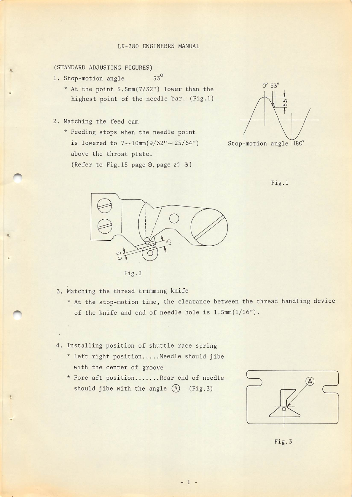
1. Stop-motion angle
* At
the
2.
Matching
highest
*
Feeding
is
above
(Refer
point
point
the
stops
lowered
the
to
5.5mm(7/32")
feed
to
throat
Fig.15
53°
lower
of
the
needle
cam
when
7—10mm(9/32"'~-25/64")
the
needle
plate.
page9,page
bar.
point
20
than
3)
the
(Fig.l)
Stop-motion
0-
53
angle
Fig.l
Fig.2
3.
Matching
* At
4.
Installing
*
*
of
Left
with
Fore
the
the
stop-motion
the
knife
right
the
aft
thread
and
position
position
center
position
trimming
time,
end
of
of
groove
the
of
needle
shuttle
Needle
Rear
knife
should jibe with the angle @ (Fig.3)
clearance
hole
race
spring
should
end
of
needle
between
is
1.5mm(l/i6").
jibe
the
thread
handling
Fig.3
device
- 1 -
Page 5
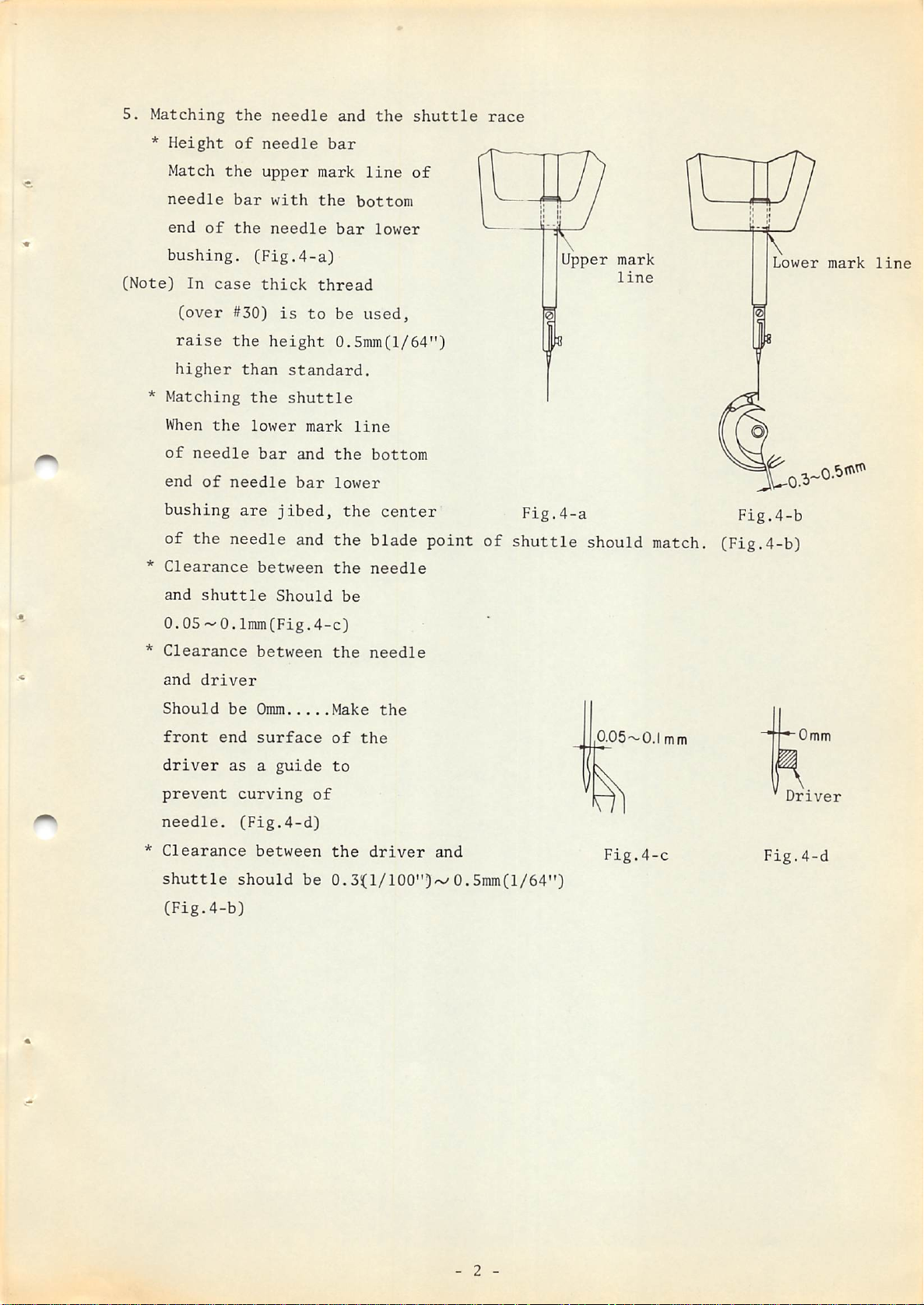
5.
Matching
*
Height
the
of
needle
needle
and
bar
the
shuttle
race
Match
needle
end
bushing.
(Note]
In
(over
raise
higher
*
Matching
When
of
end
bushing
of the needle
*
Clearance
and
of
case
the
needle
of
shuttle
the
bar
the
CFig.4-a)
#30)
the
thgin
the
lower
needle
are
upper
with
needle
thick
is
height
standard.
shuttle
bar
bar
jibed,
and
between
Should
mark
the
bar
line
bottom
lower
thread
to
be
used,
0.5mra(l/64")
mark
and
line
the
lower
the
bottom
center
the blade point
the
needle
be
of
of
Upper
Fig.4-a
shuttle
mark
line
Lower
Fig.4-b
should match. (Fig.4-b)
mark
line
0.050.
*
Clearance
and
Should
front
driver
prevent
needle.
*
Clearance
shuttle
(Fig.4-b)
lmm(Fig.4-c)
driver
be
end
as
curving
(Fig.4-d)
should
between
Omm
surface
a
guide
between
the
Make
of
the
to
of
the
be
0.3i(l/100"]-^
needle
the
driver
and
0.5mm(l/64")
0.05~0.l
Fig.4-c
mm
•Omm
Driver
Fig.4-d
- 2 -
Page 6
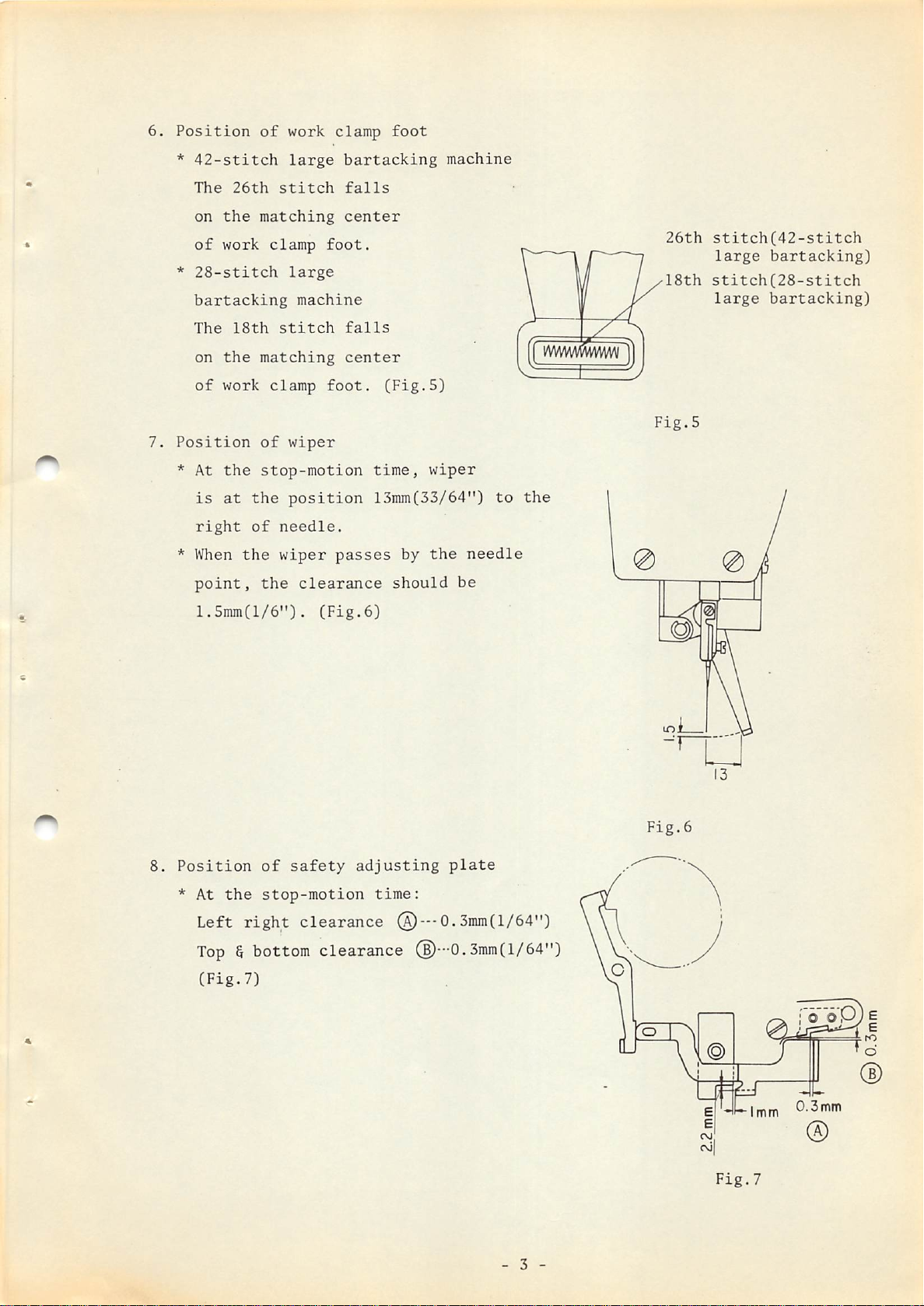
6.
7.
Position
*
42-stitch
The
on
the
of
work
*
28-stitch
bartacking
The
on
the
of
work
Position
26th
matching
18th
matching
of
of
stitch
clamp
stitch
clamp
work
large
large
machine
wiper
clamp
bartacking
falls
center
foot.
falls
center
foot.
foot
(Fig.5)
machine
mmviSww
26th
18th
Fig.5
stitch(42-stitch
large
stitch(28-stitch
large
bartacking)
bartacking)
8.
* At
* When
Position
* At
the
stop-motion
is
at
the
right
of
the
point,
1.5inm(l/6").
the
of
the
stop-motion
position
needle.
wiper
clearance
(Fig.6)
safety
time,
13inm(33/64")
passes
should
adjusting
time:
by
wiper
the
be
plate
to
needle
the
O
Fig.6
Left
right
Top&bottom
(Fig.7)
clearance ® —0.3nim(l/64")
clearance
®—0.3mm(l/64")
- 3 -
Fig.
0.3mm
©
7
Page 7
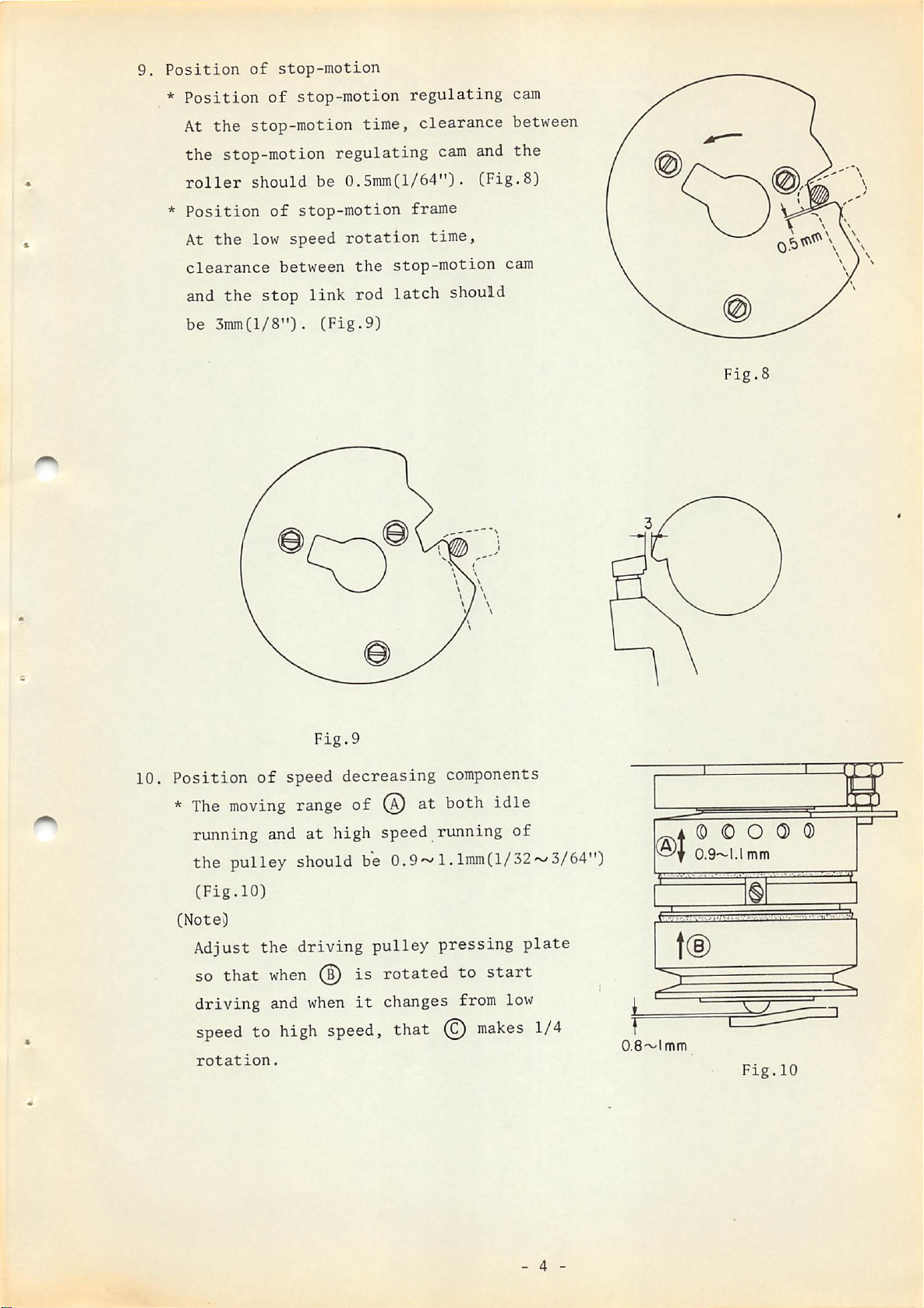
9.
Position
*
Position
At
the
of
stop-motion
of
stop-motion
stop-motion
time,
regulating
clearance
cam
between
the stop-motion
roller
*
Position
At
clearance
and
be
should
of
the
low
the
stop
3inmCl/8").
regulating
be
stop-motion
speed
between
link
(Fig.9)
cam
0.5mmCl/64")•
frame
rotation
the
rod
time,
stop-motion
latch
and
(Fig-S)
should
the
cam
Fig.
8
10.
Fig.9
Position
*
The
running and
of
moving
speed
range
at
the pulley should be
(Fig.10)
(Note)
Adjust
so
driving
speed
rotation.
that
to
the
when
and
driving
when
high
speed,
decreasing
components
of ® at both idle
high speed running
0.9*^
pulley
is
rotated
it
changes from low
1.lmm(l/32'^^3/64")
pressing
to
start
that ©
makes
of
plate
1/4
A © 0 O 0)
0.9-1.1
mm
.
...
Fig.10
Q)
-
_J
'
IT
- 4 -
Page 8
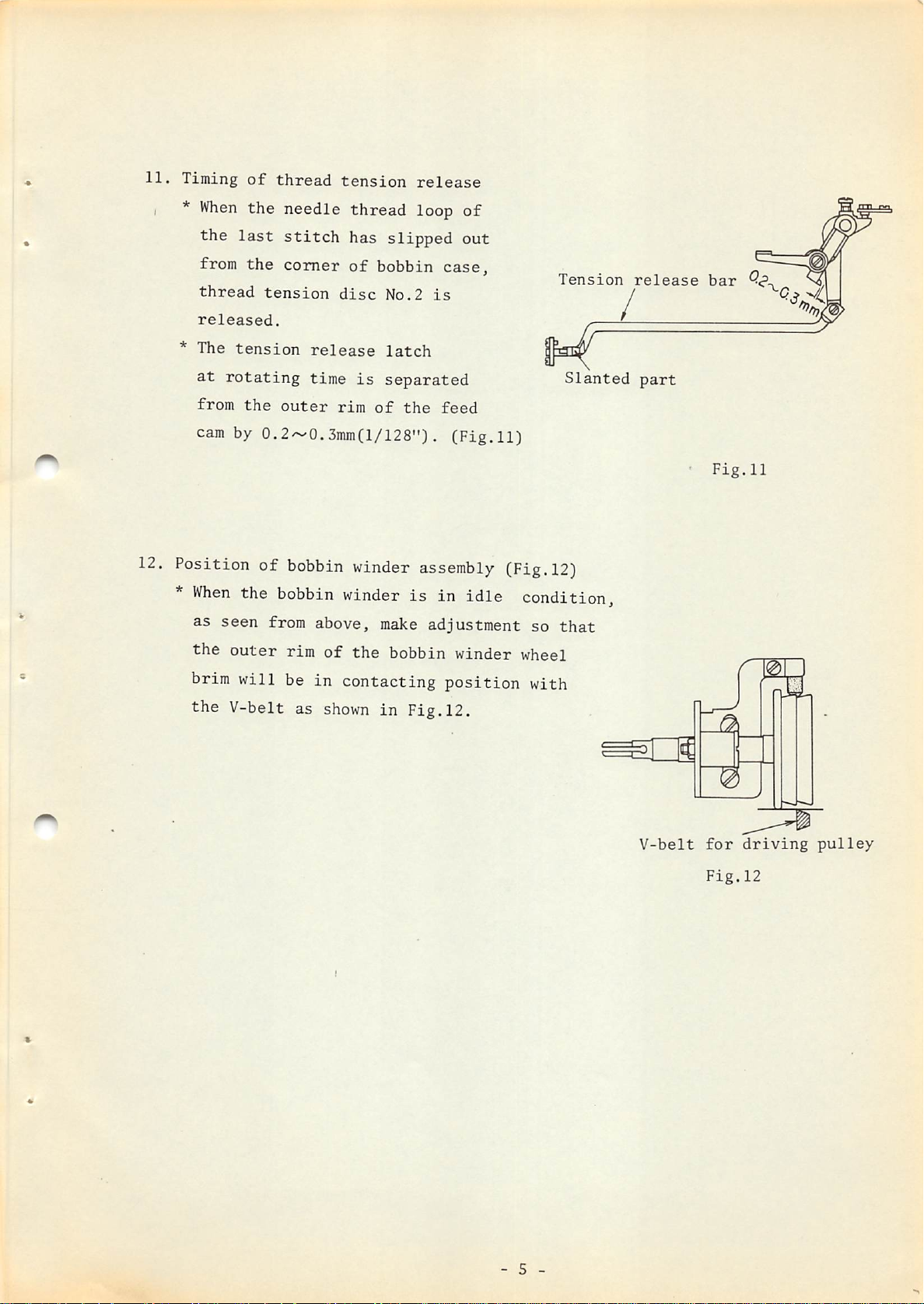
11.
I *
Timing
When
the
of
the
last
thread
needle
stitch
tension
thread
has
release
loop
slipped
of
out
*
12.
Position of
*
brim
the
from
thread
released.
The
at
rotating
from
cam
When
as
seen
the
the
comer
tension
tension
the
outer
by 0.
bobbin
the
bobbin winder
from
outer
will
V-belt as
rim
be in contacting
of
bobbin
disc
release
time
is
rim
of
3mmCl/128")
winder
above,
of
the
shown
in
No.2
latch
separated
is
the
. (Fig.11)
assembly
is
in
make
adjustment
bobbin
Fig.12.
case,
feed
idle
winder
position
Tension
(Fig.12)
condition
so
that
wheel
with
Slanted
/
release
part
•
bar
Fig.11
V-belt
- 5 -
for
Fig.12
driving
pulley
Page 9
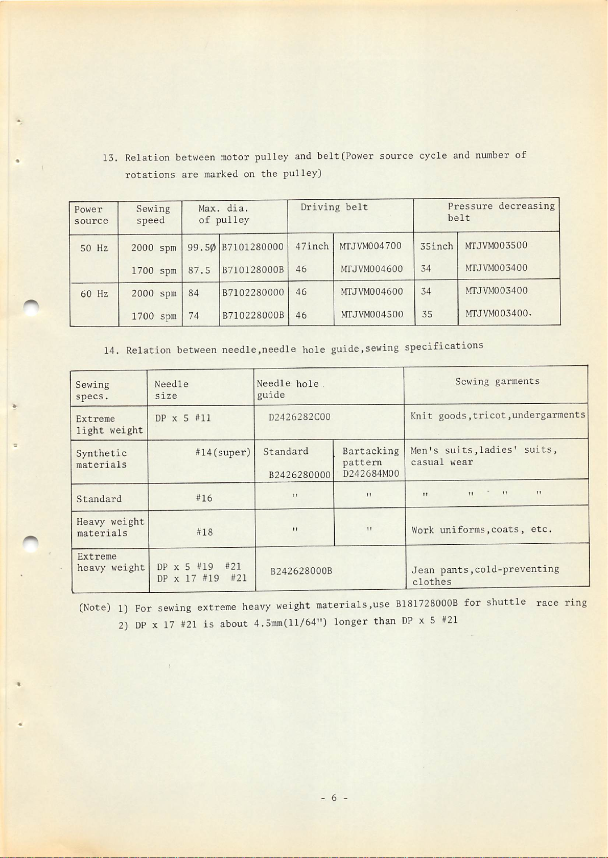
13. Relation between motor
rotations
are
marked
pulley
on
the
and belt(Power source cycle and
pulley)
number
o£
Power
source
50
Hz
60
Hz
14. Relation
Sewing
specs.
Extreme
light
Synthetic
materials
Standard
weight
Sewing
speed
2000
1700
2000
1700
spm
spm
spm
spm
between
Needle
size
DP X 5
Max.
of
pulley
99.50
87.5
84
74
B7101280000
B710128000B
B7102280000
B710228000B
needle,needle hole guide,sewing specifications
#11
#14(super)
#16
dia.
Needle
guide
D2426282C00
Standard
B2426280000
Driving
47inch
46
46
46
hole
r r
belt
MTJVM004700
MrJVM004600
MTJVM004600
OTJVM004500
.
Bartacking
pattern
D242684M00
Pressure
belt
35inch
34
34
35
Knit
Men's
casual
f T
II II
m'JVM003500
MTJVM003400
OTJVM003400
NfrJVM003400.
Sewing
goods,tricot,undergarments
suits,ladies'
wear
decreasing
garments
suits,
•• It
Heavy
materials
Extreme
heavy
weight
weight
(Note)1)For
2)
DPX17
DP X 5
DP X
17
sewing
#21isabout
#18
#19 #21
#19 #21
extreme
ft
B242628000B
heavy
weight
4.5mm(ll/64")
II
materials,use
longer
- 6 -
than
Work
uniforms,coats,
Jean
pants,cold-preventing
clothes
B181728000B
DP
x 5
for
#21
shuttle
etc.
race
ring
Page 10
(CORRECTIVE
MEASURES
FOR
FAULTY
STITCHES)
This
symptoms
breakage
(I)
Thread
*
*
*
1)
chapter
such
and
slippage
Faulty
needle
any
sewing
Principal
*
Stitches
*
Inadequate
*
Inadequate
*
Bobbin
Corrective
Prevent
*
Verify
If
not,
will
as
thread
inadequate
stitching
thread
shape
reasons
skip
length
adjustment
thread
measures
the
if
the
adjust
treat
on
slippage,thread
thread
symptoms
slips
is
at
is
out
formed.
the
first
of
the
too
short.
of
skip-stitching
shuttle
according
the
trimming.
from
trimmed
the
race
to
corrective
This
the
needle
stitch.
needle
thread
of
the
and
the
the
standard
measures
breakage,
is
a
faulty
at
thread.
take-up
first
needle
stitch.
on
skip-stitching,
condition
first
are
or
spring.
in
correcting
faulty
second
correct
procedure.
stitching
needle
by which
stitch
relationship.
the
before
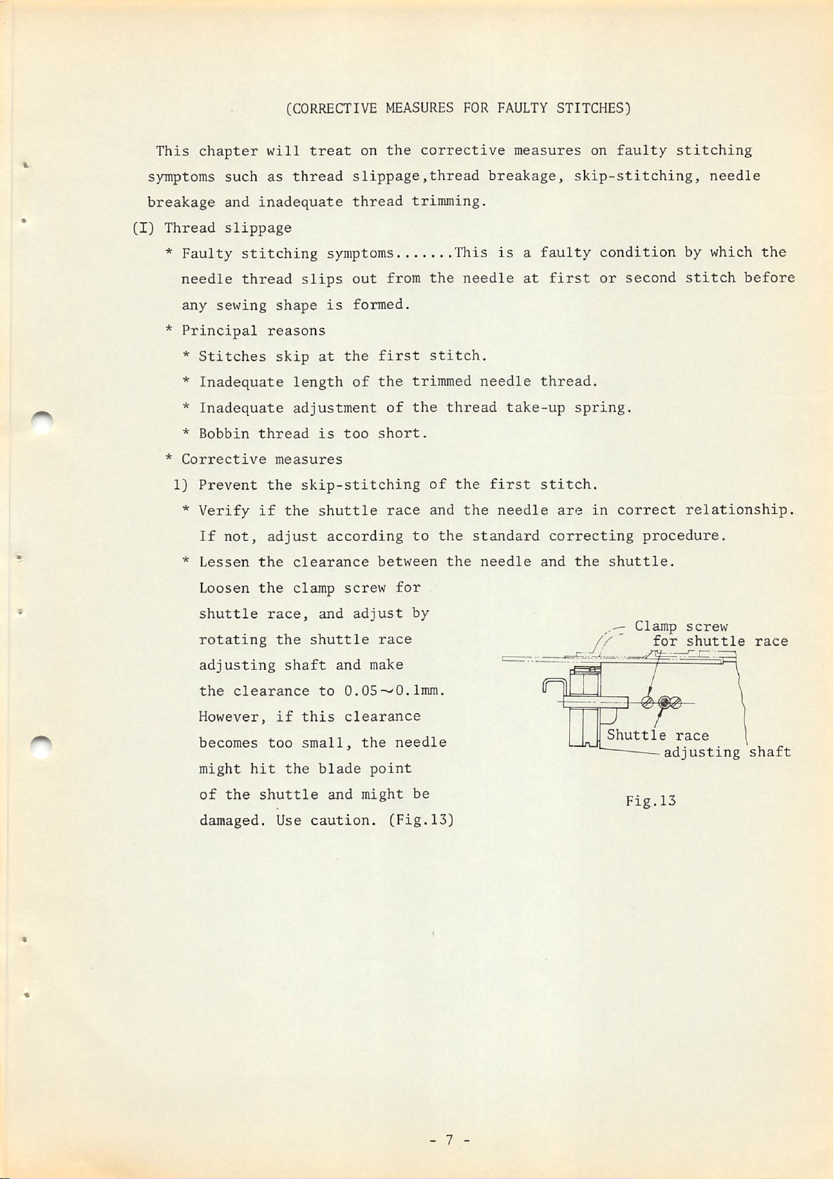
*
Lessen
Loosen
shuttle
rotating
adjusting
the
However,
becomes
might
of
damaged.
clearance
hit
the
the
the
race,
the
shaft
if
too
the
shuttle
Use
clearance
clamp
and
shuttle
to
this
small,
blade
and
caution.
between
screw
adjust
and
O-OS-^O.1mm.
clearance
race
make
the
point
might
for
needle
(Fig.13)
by
be
the
needle
and
the
shuttle.
.-j
n
Shuttle
Clamp
for
Fig.13
screw
shuttle
race
adjusting
race
shaft
- 7 -
Page 11
*
Inadequate
rotation
of
the
shuttle.
When
lap
it
Also,
the
surface
Watch
*
Prevent
sewing
To
prevent
would be
work clamp
and
the
a
convex
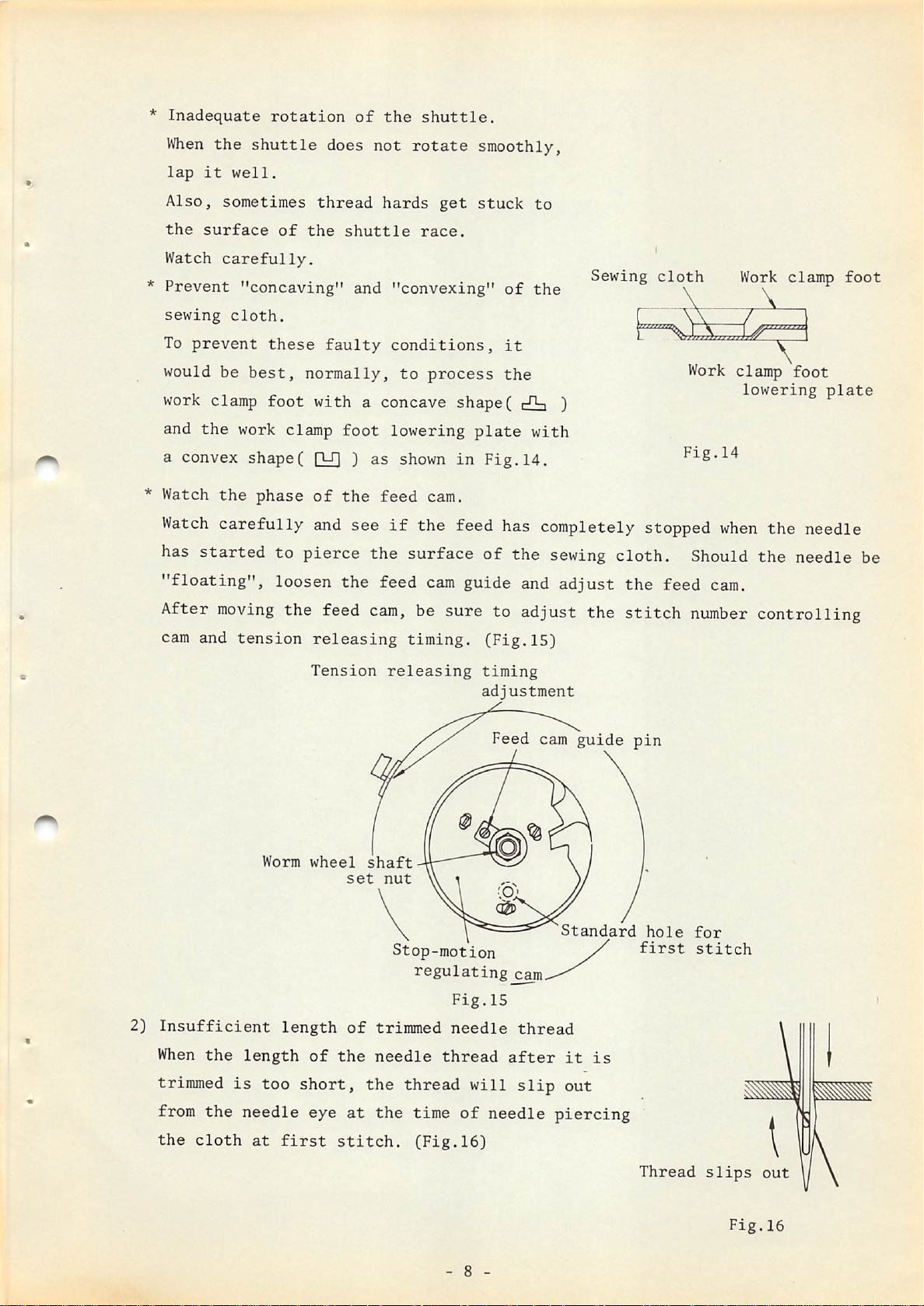
* Watch
Watch
has
started
"floating",
the
shuttle
well.
sometimes
of
carefully.
"concaving"
cloth.
these
best,
foot
work clamp
shapeC Q£| )
the
phase
carefully
to
loosen
does
thread
the
shuttle
and
faulty
normally,
with
a concave
foot
of
the
and
see
pierce
the
not
rotate
hards
race.
"convexing"
conditions,
to
process
lowering
as
shown
feed
the
feed
cam.
if
the feed has completely stopped
surface
cam
smoothly,
get
stuck
shape(
plate
in
Fig.14.
of
guide and
of
it
the
the
to
the
cHa
with
Sewing
)
sewing
adjust
cloth.
the
cloth
feed
Work
Fig.14
when
Should
cam.
Work
clamp
lowering
the needle
the
clamp
foot
foot
plate
needle be
After
cam and
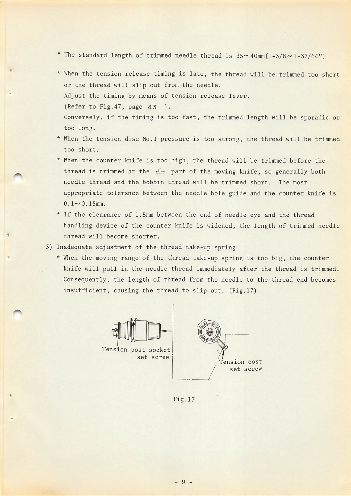
2)
Insufficient
When
moving
tension
the
Worm
length
the feed
releasing
Tension
wheel
length
of
the
cam,
shaft
set
of
nut
trimmed
needle
be sure to adjust the
timing.
releasing
Stop-motion
regulating
Fig.15
needle
thread
(Fig.15)
timing
adjustment
Feed cam
cam
thread
after
guide
Standard
it
is
stitch
pin
hole
first
number
for
stitch
controlling
trimmed
from
the
the
cloth
is
too
needle
at
short,
first
eye
the
at
stitch.
the
thread
time
(Fig.16}
- 8 -
will
of
slip
needle
out
piercing
Thread
slips
Fig.16
Page 12
*
The
standard length
of
trimmed
needle thread
is
35'-40mmCl-3/8'-l-37/64")
* When
or
the
Adjust
(Refer
Conversely,
too
long.
* When
too
short.
* When
thread
needle
appropriate
0.1^0.
*
If
the
handling
thread
the
tension
thread
the
to
the
tension
the
counter
is
thread
ISmm.
clearance
device
will
will
timing
Fig.47,
if
the
trimmed
and
tolerance
become
release
by
page
disc
knife
at
the
of
of
slip
means
timing
No.l
the
bobbin
between
l.Smm
the
shorter.
timing
out
of
4-3
is
pressure
is
too
c£]ii
between
counter
from
tension
).
too
high,
part
thread
the
is
the
fast,
knife
late,
needle.
is
the
of
will
needle
the
is
the
release
the
too
thread
the
be
hole
end
widened,
thread
lever.
trimmed
strong,
moving
trimmed
guide
of
needle
will
will
length
the
be
knife,
short.
and
eye
the
thread
trimmed
so
the
and
length
be
trimmed
will
generally
The
counter
the
of
be
sporadic
will
before
most
thread
trimmed
too
be
both
knife
short
or
trimmed
the
is
needle
3)
Inadequate
*
adjustment
When
knife
Consequently,
insufficient,
the
will
moving
pull
the
causing
Tension
range
in
the
length
post
of
set
the
of
needle
the
socket
screw
thread
the
of
thread
thread
thread
thread
Fig.17
take-up
take-up
immediately
from
to
slip
spring
the
out.
.'Tension
spring
needle
(Fig.17)
set
is
after
to
post
screw
too
the
the
big,
thread
thread
the
counter
is
end
trimmed.
becomes
- 9 -
Page 13
*
When
the
moving
range
of
the
thread
take-up
spring
is
too
big,
loosen
the
*
(Note)
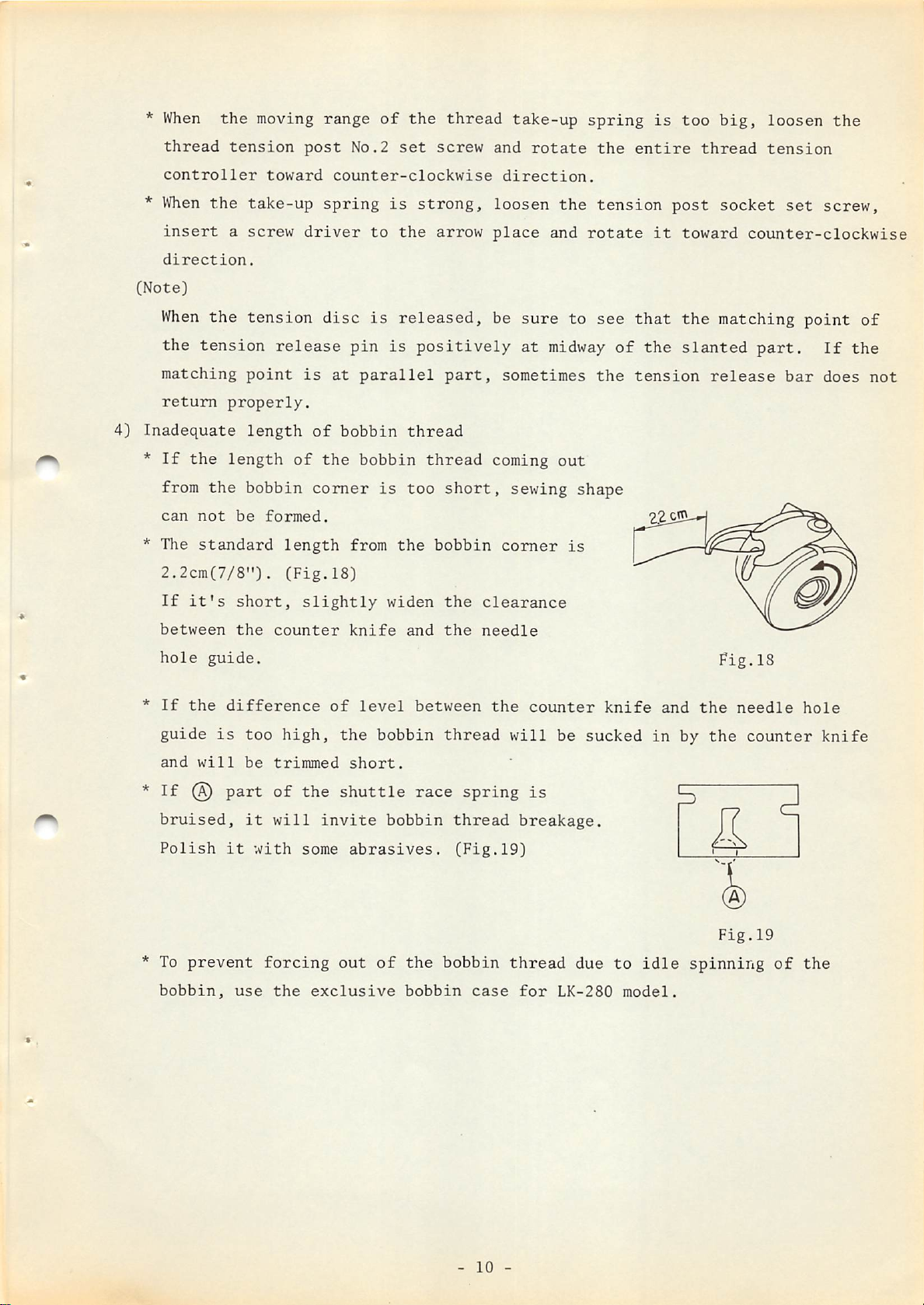
4)
Inadequate
*
*
thread
controller
When
insert
direction.
When
the
tension
the
a
the
tension
matching
return
If
from
can
The
2.2cm(7/8").
If
properly.
the
length
the
not
standard
it's
be
short,
toward
take-up
screw
tension
release
point
length
of
bobbin
formed.
length
(Fig.18)
post
No.2
counter-clockwise
spring
driver
disc
to
is
pin
is
at
parallel
of
bobbin
the
bobbin
comer
from
slightly
set
is
strong,
the
released,
is
positively
thread
is
too
the
widen
screw
arrow
part,
thread
short,
bobbin
the
and
rotate
direction.
loosen
place
be
sure
at
sometimes
coming
sewing
comer
clearance
the
and
rotate
to
midway
out
shape
is
the
entire
tension
see
that
of
the
tension
it
the
thread
post
toward
the
slanted
tension
socket
set
counter-clockwise
matching
part.
release
bar
screw,
point
If
does
of
the
not
between
hole
*
If
guide
and
*
If
bruised,
Polish
* To
bobbin,
guide.
the
difference
is
will
@
part
it
prevent
the
too
be
it
use
counter
high,
trimmed
of
will
with
forcing
the
of
the
the
shuttle
invite
some
out
exclusive
knife
level
and
bobbin
short.
bobbin
abrasives.
of
the
bobbin
the
between
thread
race
thread
(Fig.19)
bobbin
needle
the
spring
case
counter
will
be
is
breakage.
thread
for
LK-280
knife
sucked
due
to
model.
in
idle
and
by
spinning
Pig.18
the
the
Fig.19
needle
counter
of
hole
knife
the
-
10
-
Page 14
(II)
(A)
Thread
Thread
*
Faulty
*
Principle
breakage
breakage
condition
reasons
during
stitching
Here,
the
*
Shuttle
*
Thread
*
Bruise
*
Too
*
Bruise
*
Needle
*
Bruise
operation
it
bobbin
small
means
thread
is
bites
of
the
clearance
of
the
hits
of
the
the
bruised
into
driver
needle
the
needle
breaking
in
the
the
between
work
middle
shuttle
hole
clamp
of
the
guide
foot
the
of
needle
stitching
driver
thread
and
and
operation.
the
shuttle
*
Corrective
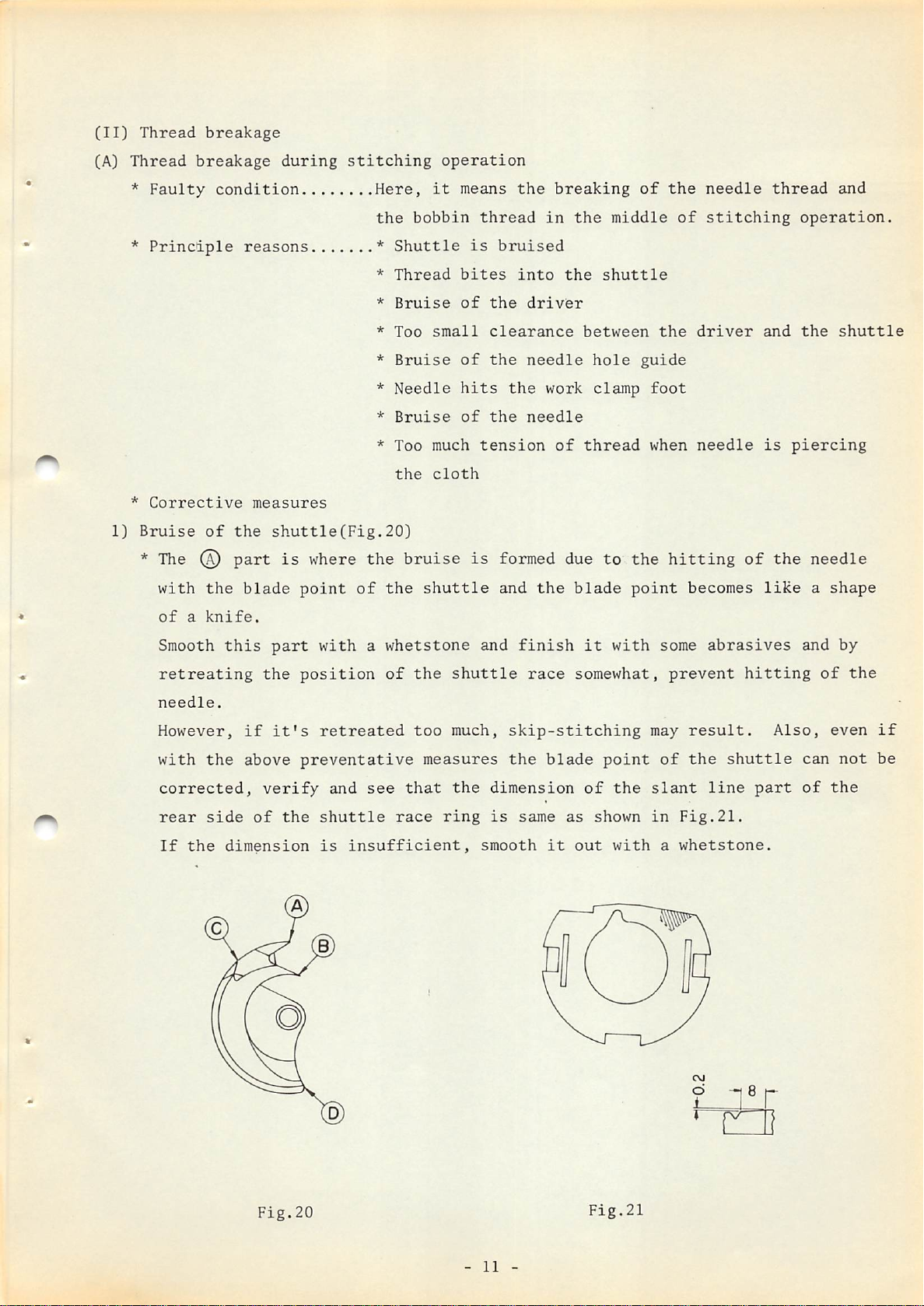
1)
Bruise
* The (a)
of
with
of
a
the
knife.
Smooth
retreating
needle.
However,
with
the
corrected,
rear
side
If
the
measures
the
shuttle(Fig.20}
part
blade
this
part
the
if
it's
above
verify
of
dimension
is
where
point
with
position
retreated
preventative
and
the
shuttle
is
* Too much
the
the
bruise
of
the
a
whetstone
of
the
too
see
that
race
insufficient,
tension
cloth
is
shuttle
and
shuttle
much,
measures
the
ring
smooth
of
formed due
and
the
finish
race
skip-stitching
the
blade
dimension
is
same
it
thread
to
blade
it
with
somewhat,
point
of
the
as
shown
out
with
when
the
point
may
slant
in
needle
hitting
becomes
some
prevent
result.
of
the
Fig.21.
a
whetstone.
is
of
like
abrasives
hitting
shuttle
line
part
piercing
the
and
Also,
can
of
needle
a
shape
by
of
the
even
not
the
if
be
Fig.20
-
11
-
Fig.21
CM
d
1
Page 15
*
The
(D
part is
the
place
where
bruise
is
formed
when
the
needle
becomes
curved
or
broken.
This
be
*
is
given.
The
© part is the place
exchanged
This
does
to
stitch.
*
The
(d)
out
of
happen
careful.
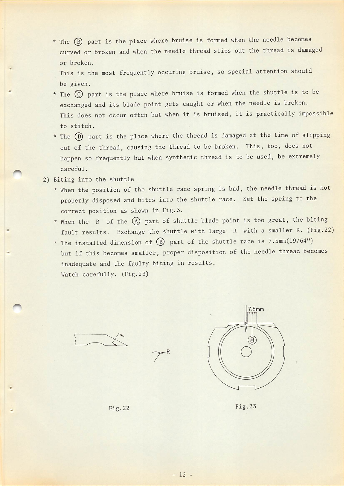
2)
Biting
*
into
When
the position of the shuttle race spring
properly disposed
correct
or
broken and
the
most
and
not
part
the
thread,
its
occur
is
when
frequently occuring bruise, so special
blade point gets
often
the place
causing
so frequently but
the
shuttle
and
position
as shown
the
needle
where
but
where
when
bruise is
when
the thread is
the
thread
synthetic thread
bites into the
in
Fig.3.
thread
caught
it
is
to
shuttle
slips
out
the
thread
attention
formed
or
bruised,
be broken.
when
when
damaged
is
is
bad, the needle thread
the shuttle is to
the needle is broken.
it
is
practically
at the time of slipping
This,
to be used, be extremely
too,
race. Set the spring to the
is
damaged
should
impossible
does not
is
be
not
*
When
fault
*
The
but
inadequate
Watch
the R of the ® part of shuttle blade point
results.
installed
if
this
carefully.
dimension
becomes
and
the
Exchange
smaller,
faulty
(Fig.23)
the
shuttle
with large R with a smaller
of ® part of the shuttle race
proper
biting
disposition
in
results.
of
is
too great, the biting
is
7.Smm(19/64")
the
needle
7.5mtn
thread
R.
(Fig.22)
becomes
Fig.22
-
12
-
Fig.23
Page 16
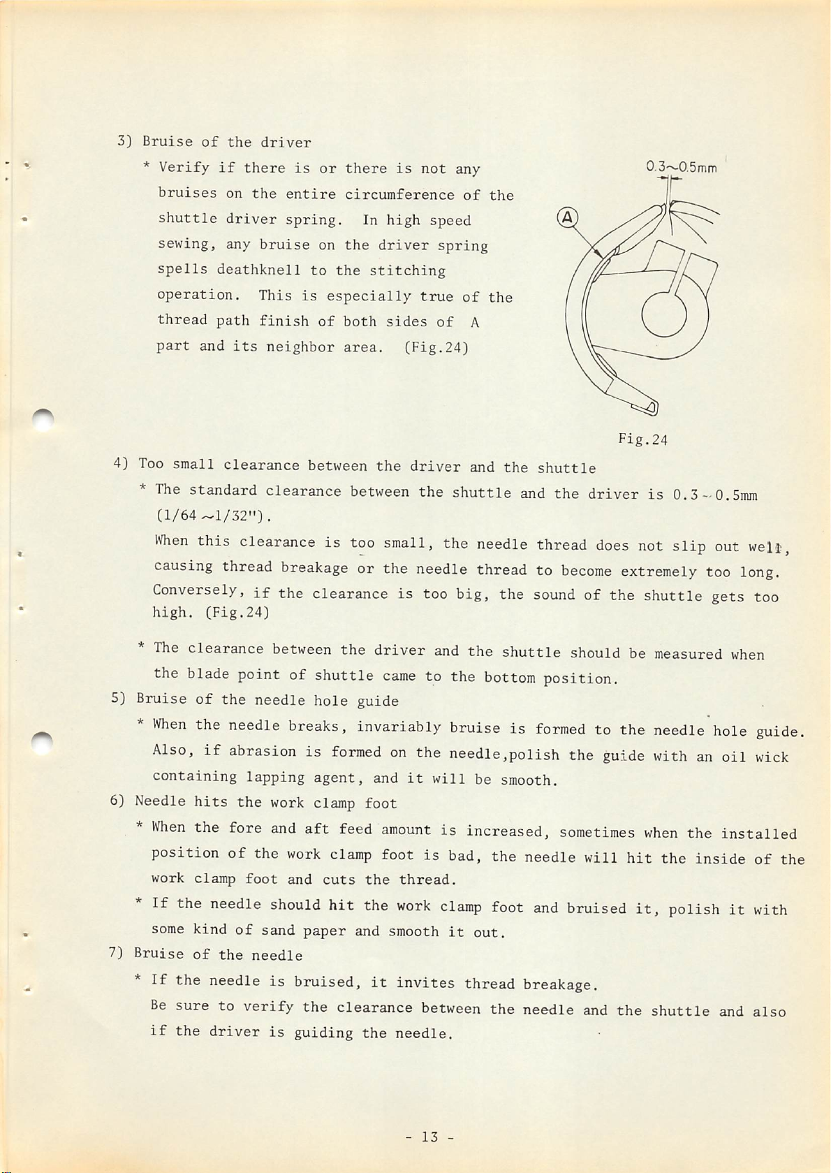
3)
Bruise
*
Verify
of
if
the
driver
there
is
or
there
is
not
any
0.3~0.5mm
4) Too
*
Conversely,
high.
bruises
shuttle
sewing,
spells
operation.
thread
part
small
The
(1/64^1/32").
When
causing
on
driver
any
deathknell
path
and
clearance
standard
this
thread
(Fig.24)
the
entire
spring.
bruise
This
finish
its
neighbor
clearance
clearance
breakage
if
the clearance is too big, the
on
to
the
is
especially
of
both
area.
between
is
circumference
In
high
the
driver
stitching
true
sides
(Fig.24)
the
driver
between
too
the
small,
speed
spring
of
shuttle
the
of
of
the
A
and
needle
the
the
or the needle thread to
shuttle
and
thread
sound
Fig.24
the
driver
does
become
is
0.3-0.5mm
not
slip
extremely
too
of the shuttle gets too
out
welit,
long.
*
The
the blade point of shuttle
5) Bruise
*
When
Also,
containing
6) Needle
When
position
work
If
some
7)
Bruise
*
If
Be
if
clearance between
of
the needle
the
needle
if
abrasion is
lapping
hits
the
the fore
of
clamp
foot
the needle
kind
of
of
the
breaks, invariably bruise is
work
and
the
work
and
should
sand
needle
hole
formed
agent,
clamp
aft
clamp
cuts
hit
paper
the
feed
the needle is bruised,
sure
the
to
verify
driver
is
the
clearance between the needle and
guiding
driver
came
guide
on
and
foot
amount
foot
the
the
and smooth
it
the
and
the
shuttle
to the
bottom
the needle,polish the guide with
it
will
is
thread.
work
be
is
increased,
bad,
clamp
it
out.
smooth.
the
foot
invites thread breakage.
needle.
position.
formed
sometimes
needle
and
bruised
should be measured
to the
needle
an
will
when
hit
it,
the
the
the
polish
shuttle
inside
when
hole
oil
guide.
wick
installed
of
it
with
and
also
the
-
13
-
Page 17
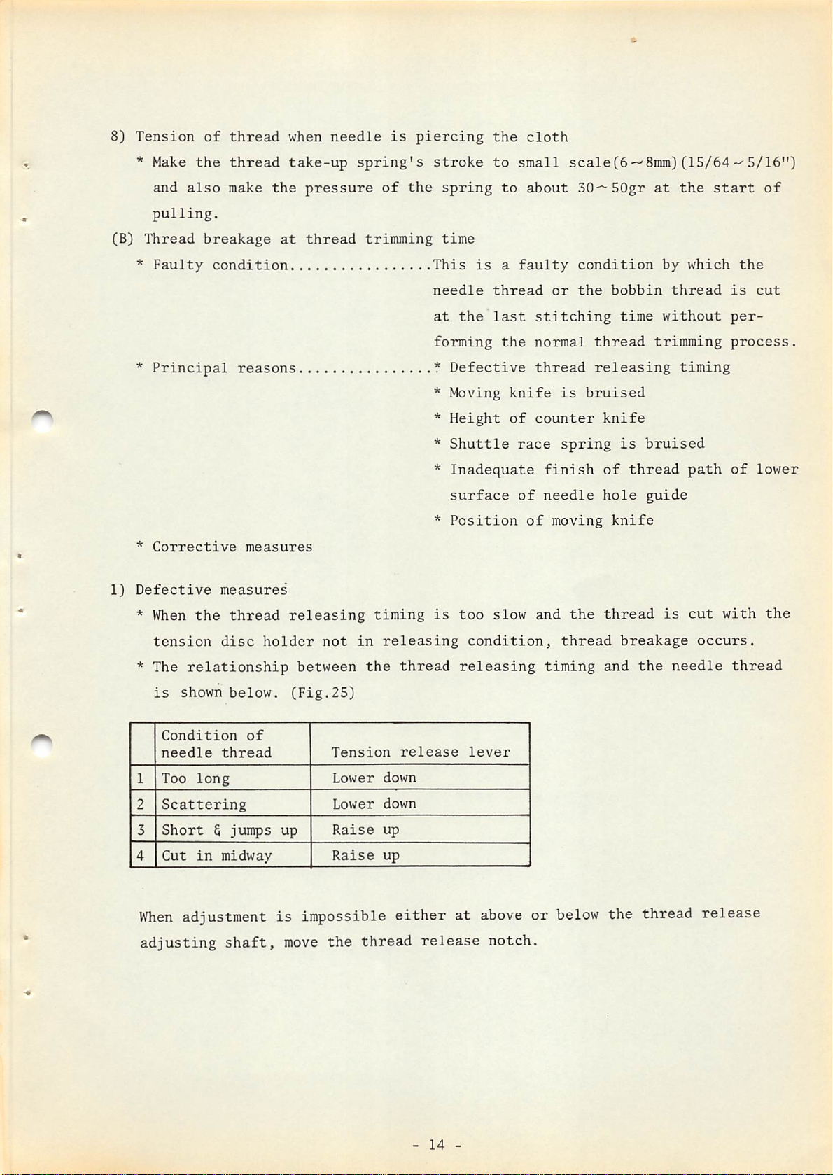
8)
Tension
of
thread
when
needle
is
piercing
the
cloth
(B)
* Make
and
pulling.
Thread
*
Faulty
*
Principal
*
Corrective
the
also
breakage
condition
thread
make
reasons
measures
take-up
the
at
pressure
thread
spring's
of
trimming
the
stroke
spring
time
This
needle
at
is
the
forming
*
Defective
*
Moving
*
Height
*
Shuttle
*
Inadequate
surface
*
Position
to
to
a
thread
last
the
knife
of
small
about
faulty
stitching
normal
thread
counter
race
finish
of
needle
of
scale(6-^8mm)(15/64-^5/16")
30—50gr
condition
or
the
is
bruised
spring
moving
bobbin
thread
releasing
knife
of
hole
knife
time
is
thread
at
the
by
thread
without
trimming
timing
bruised
guide
start
which
path
of
the
is
cut
per
process.
of
lower
1)
Defective
*
When
tension
* The
is
shown
Condition
needle
1
Too
2
Scattering
3
Short
4
Cut
When
adjustment
adjusting
measures
the
thread
disc
relationship
below.
of
thread
long
§
jumps
in
midway
shaft,
releasing
holder
(Fig.
up
is
move
not
in
between
25)
Tension
Lower
Lower
Raise
Raise
impossible
the
thread
timing
releasing
the
down
down
up
up
either
thread
release
release
is
at
too
slow
condition,
releasing
lever
and
thread
timing
the
above or below the
notch.
thread
breakage
and
is
the
needle
thread
cut
occurs.
release
with
thread
the
-
14
-
Page 18
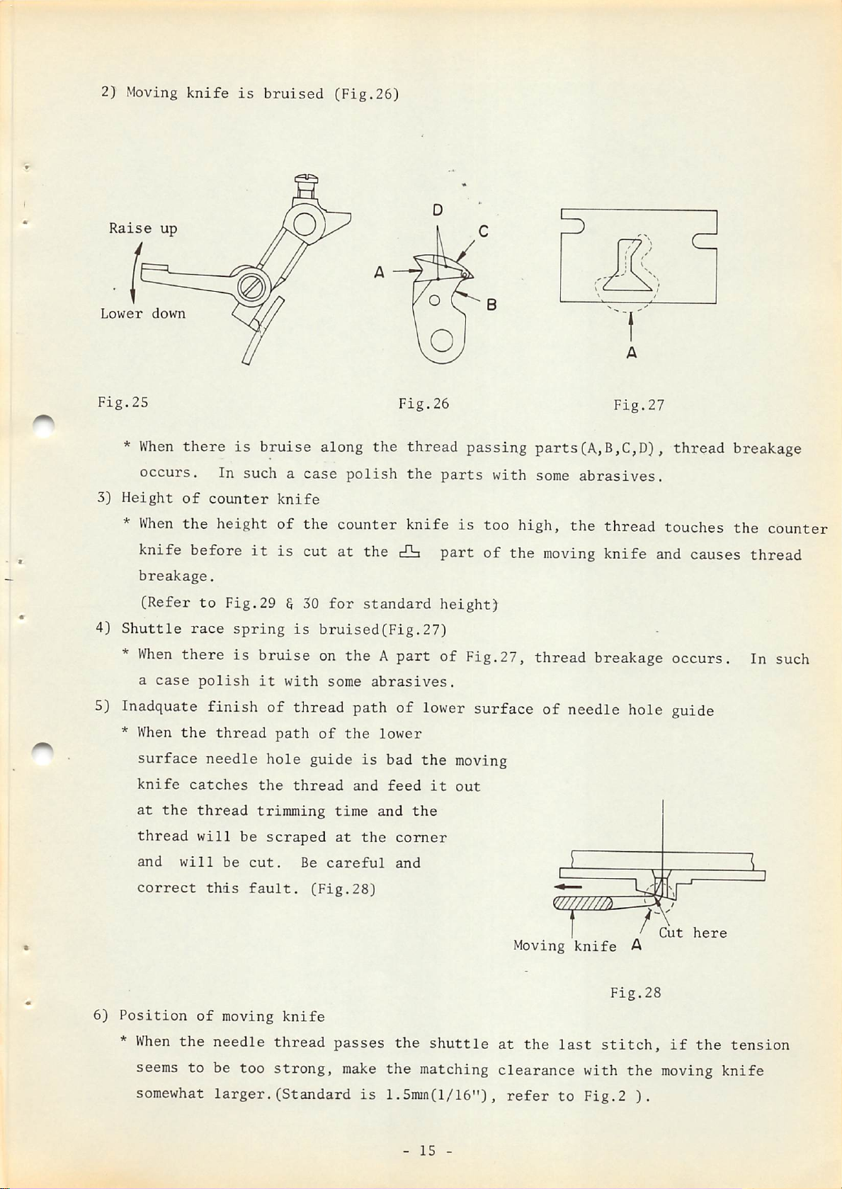
2) Moving
knife
is
bruised
(Fig.26)
Raise
Lower
Fig.25
*
3)
Height
*
4}
Shuttle
up
down
When
When
occurs.
there
of
the
In
counter
height
knife before
breakage.
(Refer
to
race
Fig.29
is
bruise
suchacase
knife
of
it
is
6 30
spring
is
along
the
cut
for
bruised(Fig.27)
the
polish
counter
at
the
standard
Fig.26
thread
the
knife
cO=t
passing
parts
is
part
height)
with
too
of
5
parts(A,B,C,D),
some
high,
the
abrasives.
the
moving
5
Fig.27
thread
thread
touches
knife and causes thread
breakage
the
counter
*
When
a
there
case
5) Inadquate
*
6)
When
surface
knife
at
thread
and
correct
Position
*
When
the
the
will
the
polish
finish
thread
needle
catches
thread
will
be
this
of
moving
needle
is
bruise
it
with
on
theApart
some
abrasives.
of Fig.27,
thread
breakage occurs. In such
of thread path of lower surface of needle hole guide
hole
the
trimming
be
scraped
cut.
fault.
path
of
guide
thread
Be
(Fig.28)
the
and
time
at
careful
is
the
lower
bad
feed
and
comer
and
the
the
it
moving
out
(^777777m
T '
knife
thread
passes
the
shuttle
Moving
at
the
knife
last
A
Fig.28
stitch,
v
f
J V
Cut
I—'
if
here
the
'
tension
seems
somewhat
to
be
too
strong,
larger.(Standard
make
is
the
matching
1.5mm(l/16"),
-
15
-
clearance
refer
to
with
Fig.2
the
).
moving
knife
Page 19
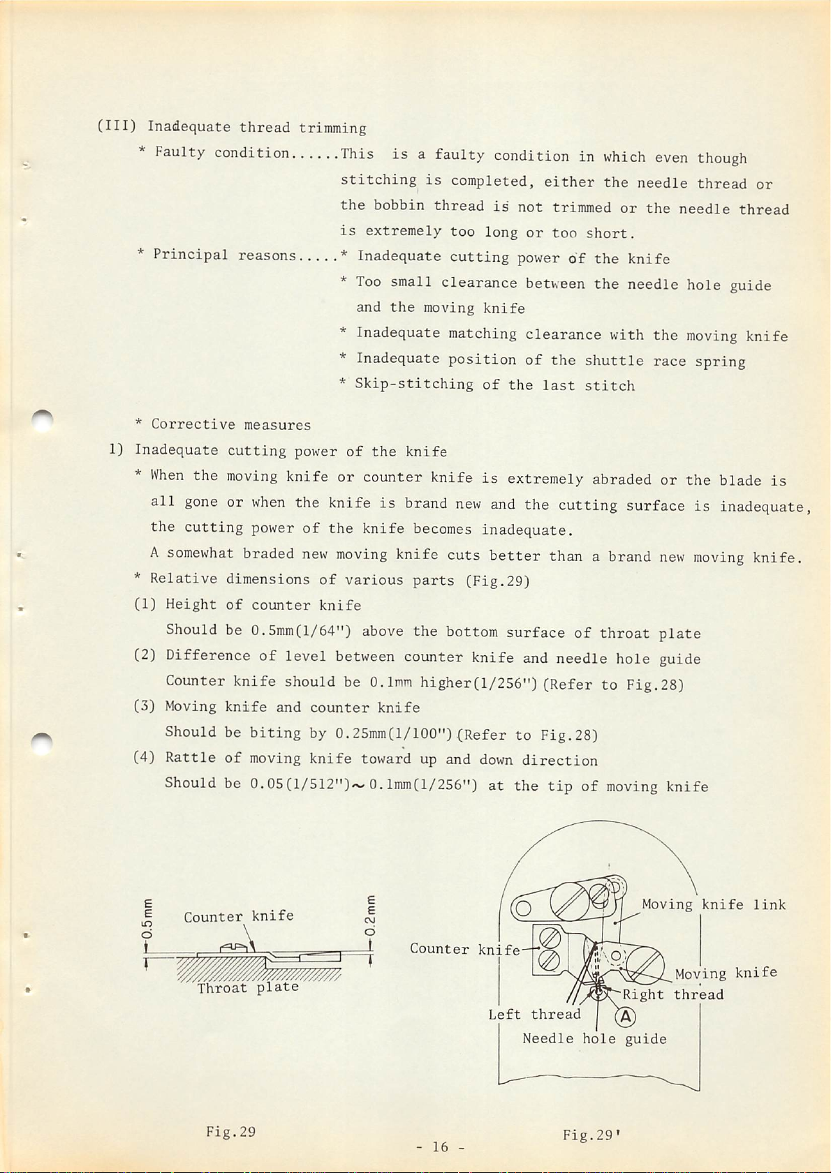
(Ill)
Inadequate
thread
trimming
Faulty condition
*
Principal
*
Corrective
1) Inadequate
*
When
all
the
A
the
gone
cutting
somewhat
This
stitching
the
is
is
bobbin
extremely
reasons * Inadequate
*
Too
small clearance between
and
the
* Inadequate matching
* Inadequate
*
Skip-stitching
measures
cutting
moving
or
when
power
braded
power
of
the
knife
knife or counter knife
the knife is brand
of
the
knife
new
moving
knife cuts
a faulty condition in
is
completed,
thread
too
cutting
moving
position
new
becomes
is
long
knife
of
is
and
inadequate.
better
either
not
trimmed
or
too
power
of
clearance
of
the
the
last
extremely abraded or
the cutting surface is inadequate,
than a brand
which
the
or
short.
the
the
with
shuttle
stitch
even
needle
the
though
thread
needle
or
thread
knife
needle hole guide
the
race
new
moving
spring
the
moving
knife
blade
knife.
is
*
Relative
(1)
Height
Should be 0.5mm(l/64")
(2) Difference
Counter
(3)
Moving
Should be
(4)
Rattle
dimensions
of
counter
of
level
knife
knife
should be
and
biting
of
moving
of
various
knife
above
between counter knife and needle hole guide
0.1mm
counter
knife
by 0.2Smm(l/lQ0")(Refer
knife
toward up and
Should be 0. OS(l/512")'^-> 0. lmm(l/256")
Counter
Throat
knife
plate
parts
the bottom surface
(Fig.29)
of
throat
higher(1/256") (Refer to Fig,28)
to
Fig.28)
Counter
down
knife
at
Left
direction
the
tip
thread
of
moving
Moving
•Right
plate
knife
Moving
thread
knife
link
knife
Needle
Fig.29
-
16
-
Fig.29»
hole
guide
Page 20
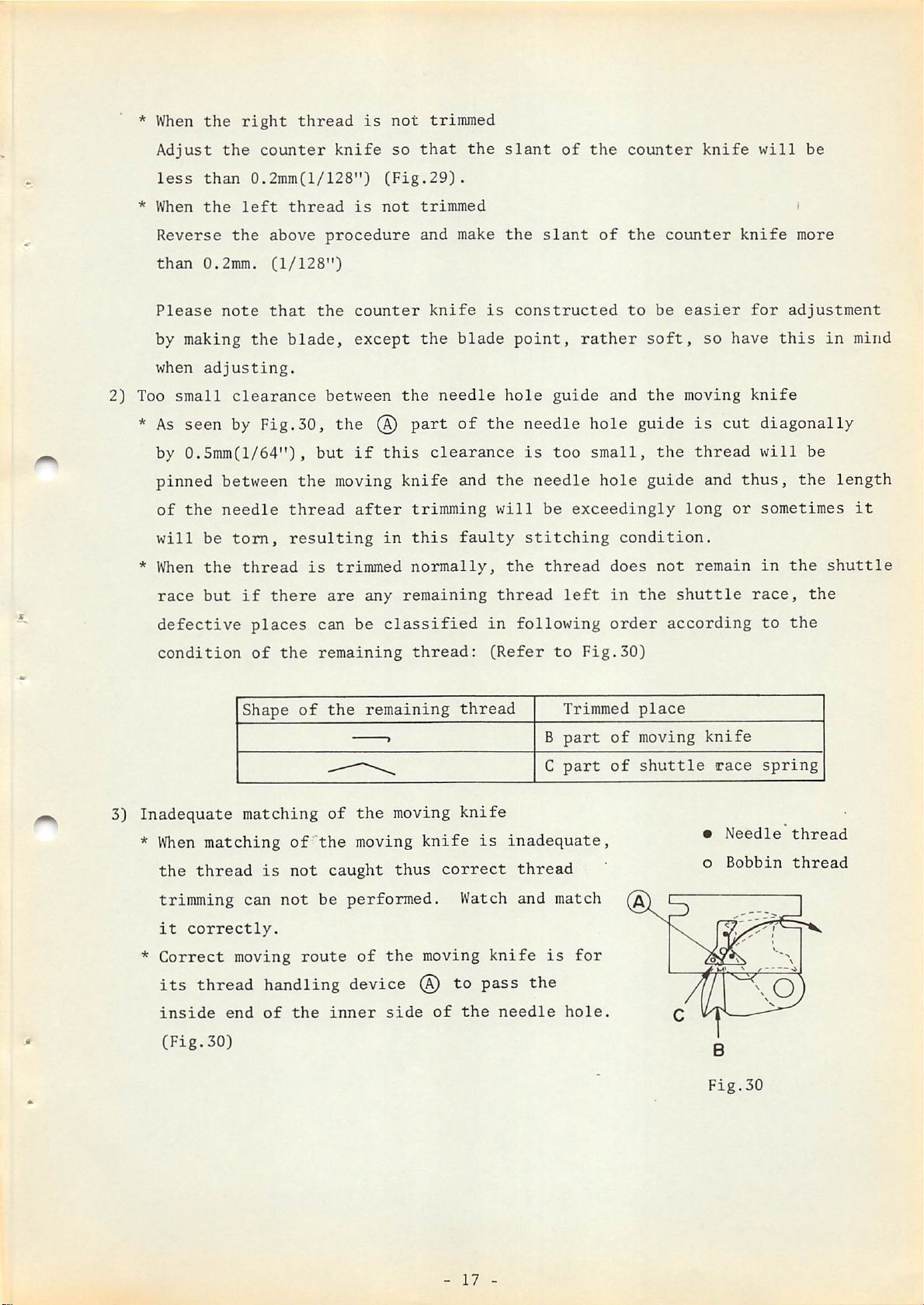
* When
the
right
thread
is
not
trimmed
*
2) Too
*
* When
Adjust
less
When
Reverse
than
Please
by
when
small
As
by
pinned
of
will
race
the
than
the
0.2mm(l/128")
left
the
0.2mm.
note
making
adjusting.
the
clearance
seen by Fig.30,
0.5mm(l/64"),
between
the
needle
be
torn,
the
thread
but
if
counter
thread
above
(1/128")
that
blade,
the
thread
resulting
there
knife
procedure
the
between
the
but
moving
is
trimmed
are
so
(Fig.29).
is
not
counter
except
@
if
this
after
in
any
that
trimmed
and
make
knife
the
blade
the
needle
part
of
clearance
knife
trimming
this
normally,
and
faulty
remaining
the
slant
the
is
point,
hole
of
slant
constructed
rather
guide
the
of
counter
the
to
and
the needle hole guide
is
too
small,
the
will
stitching
the
thread
needle
be
thread
hole
exceedingly
condition.
does
left
in
be
soft,
the
the
guide
not
the
knife
counter
easier
so
moving
is
thread
and
long
remain
shuttle
will
knife
for
have
knife
cut
diagonally
will
thus,
or
sometimes
in
race,
be
more
adjustment
this
in
be
the
the
shuttle
the
mind
length
it
3)
Inadequate
*
*
defective
condition
When
matching
the
thread
trimming
it
correctly.
Correct
its
thread
inside
(Fig.30)
places
of
Shape
matching
is
can
moving
the
of
of
not
not
route
can
remaining
the
of
"the
caught
be
handling device ®
end
of
the
inner
be
classified
thread:
remaining
»
^
the
moving
moving
thus
performed.
of
the
side
thread
knife
knife
correct
Watch
moving
to
of
the
in
following
(Refer
is
inadequate,
thread
and
knife
pass
needle
B
C
is
the
to
Fig.30)
Trimmed
part
part
match
for
hole.
order
place
of
moving
of
shuttle
according
knife
race
•
Needle
o
Bobbin
to
the
spring
thread
thread
-
17
-
Fig.30
Page 21

4)
Inadequate
position
of
the
shuttle
race
spring
5)
Skip-stitching
* When
ly.
Needle
*
*
* When
in
the
caught
Adjust
Faulty
Principal
the
the
case
proper
the
by
the
breakage
condition
position
of
inadequate
position
of
the
stitches
the
knife
needle
reasons....*
of
of
last
skip
and
and
the
shuttle
matching
the
shuttle
stitch
at
the
thus
the
shuttle.
This
means
operation
Insufficient
*
Inadequate
last
the
race
thread
the
timing
is
of
the
race
stitch,
(Fig.4)
needle
guide
bad,
moving
spring.
the
will
breaks
of
of
the
not
front
feed
same
knife
(Fig.3)
needle
be
in
faulty
occurs.
thread
trimmed.
the
surface
does
middle
of
condition
Adjust
not
of
sewing
the
driver
it
get
as
to
*
Corrective
1)
Insufficient
* As shown
the
shuttle
Therefore,
2j
Inadequate
*
When
and
adjust
The
point
in
driver,
to
timing
the
cloth
thus
needle
the
standard
has
measures
guide
Fig.4-d,
the
cause
adjust
feed
adjustment
come
*
*
*
of
front
unless
needle
needle
so
that
of
feed
feed
movement does
starts
timing.
down
to
Bruise
Needle
Inadequate
may
breakage.
on
hits
surface
the
be
curved
the
needle
needle
assembling
of
needle
not
to
"flow",
is
to
needle
match so
7'^10mm(9/32'^
the
the
when
will
25/64")
hole
work
driver
is
stop
breakage
that
guide
clamp
of
guided
it
pierces
be
guided
before
the
above
foot
moving
at
the
by means
the
occurs.
feeding
the
knife
front
the
needle
stops
throat
cloth
Refer
end
and
of
the
pierces
to
when
plate.
surface
hits
driver.
the
Fig.15
the
of
the
cloth
and
needle
-
18
-
Page 22

3)
Needle
* A
hole
needle,
guide
once
broken,
sometimes
bruises
inside
suface
of
the
needle
hole
4)
Hits
*
5)
Inadequate
guide
the
point
The
bruise
with
Also,
are
please
use
the
If
the
foot,
when
extreme
or
due
needle
will
needle
so
a
new
as
there
available
refer
correct
work
needle
needle
changing
caution.
assembling
to
hole
be
caught
hole
easily,
one.
depending
to
ones.
clamp
hits
breakage
are
the
the
guide.
is
heat-treated
but
many
page
foot
the
stitch
curving
of
Unless
again
in
by
case
kinds
on
the
6 No.14 and
work
occurs,
of
clamp
size,
moving
the
this
the
harder
it
of
usage,
so
apply
knife
needle
bruise
bruise
is
bruised
needle
when
causing
than
hole
piercing
is
smoothly
needle
the
needle
toagreater
guide
in
the
cloth,
removed,
breakage.
and
so
it
degree,
combination
Moving
connecting
may
the
needle
should
exchange
with
knife
bruise
not
it
needles
link
(V)
1)
* When
if
the
knife
and
will
needle
knife
CFig.31)
Cautions
Extreme
materials
Thread
removing
installation
connecting
the
needle
hit
the
to
will
on sewing
caution
with
breakage
moving
be
broken
be
should
synthetic
the
knife
link
is
dropped,
bruised.
synthetic
due
to
components,
of
the
is
knife
or
the
be
exercised
thread
heat
moving
forgotten
the
causing
moving
Be
careful.
materials
as
needle
the
for
under:
with
sewing
synthetic
synthetic
Fig.31
thread
or
mixed
synthetic
Due
to
the
to
should
cause
be
the
taken:
resistance
cloth
to
of
be
the
cut
cJoth
or
stick
at
-
19
piercing
by
melting,
-
time,
following
the
needle
corrective
gets
over-heated
measures
Page 23

*
Change
to a
pulley
for
synthetic
materials(SOHz
B710128000B,
60Hz
B710228000B).
Sewing speed
*
Use
silicon
machine", page 5 and No,7, page 4)
*
Use
super needle for
*
If
a fine needle
effective.
2)
To
prevent the thread
*
During
thread
3) Thread
*
When
the
For
the
guideAtoward
releasing
thread
feed.
adjustment,
adjustmentsothat
4) Bruise on the
*
In
sewing
should
oil
be
lubricant.(Refer to
synthetic
is
used, piercing resistance will be less
from
sewing,ifthe
left
at
start
releasing
occurs
refer to
the
shuttle
synthetic
driver
materials,
1,700
s.p.m.
splitting
thread
and
of sewing
at
the
chapter
feed
stops
spring
INSTRUCTION
materials.
finely
should
make
the
the
start of
on
near
bruise
is
BOOKon"How
split
thread
finely
take-up
sewing,
"Matching
the
10mmC25/64")
liable
the
to
and
or
breaks,
lever
adjust
feed
cam"
rangetobe
be
formedonthe
to thread the
will be
move
stroke
the
timing
and
more
the
bigger.
of
make
effective.
tail
frame
end
of
the
thread
carefully.
5)
Smooth
To
following
*
*
*
* Needle
* Needle
(VI) Inadequate
*
1)
Adjust
out
enable
Shuttle
Shuttle
Shuttle
In
case
the
the
the
parts:
driver
race
hole
bar
thread
of
timing
slipping
When
this
thread
thread
spring
spring
guide
thread
inadequate
guide B1405280000
tension
of
out
happens,
path
to
pass
thread
feed
side
of
the
smooth
smoothly,
B1813280000
B1818280000
B1815280000
B2426280000
tension
shuttle
this out
smooth
out
driver
with
the
spring,
buff, etc.
thread
path
so
watch
of
the
Within
the
effective.
the
range
describedonthe
timingoffeedsothat
Then,
the thread tension
the
chapteron"Matching
feed
-
stops
20
will
-
nearer
become
the
better.
the
feed
7mmC9/32")
cam",
rangetobe
adjust
Page 24
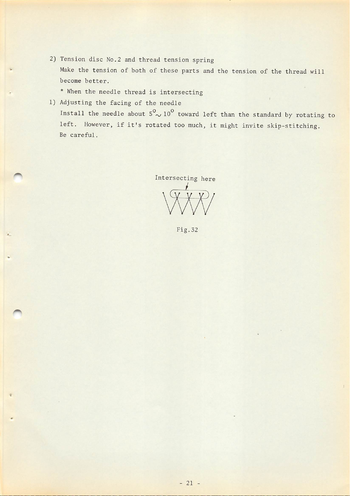
2) Tension
disc
No.2 and
thread
tension
spring
Make
become
*
1)
Adjusting
Install
left.
Be
When
careful.
the
tension
better.
the
the
the
However,
needle
facing
needle
of
thread
if
both
of
about
it's
of
these
is
intersecting
the
needle
10°
rotated
Intersecting
parts
toward
too
much,
Fig.32
and
left
here
it
the
than
might
tension
the
invite
of
the
standard
skip-stitching.
thread
by
rotating to
will
-
21
-
Page 25
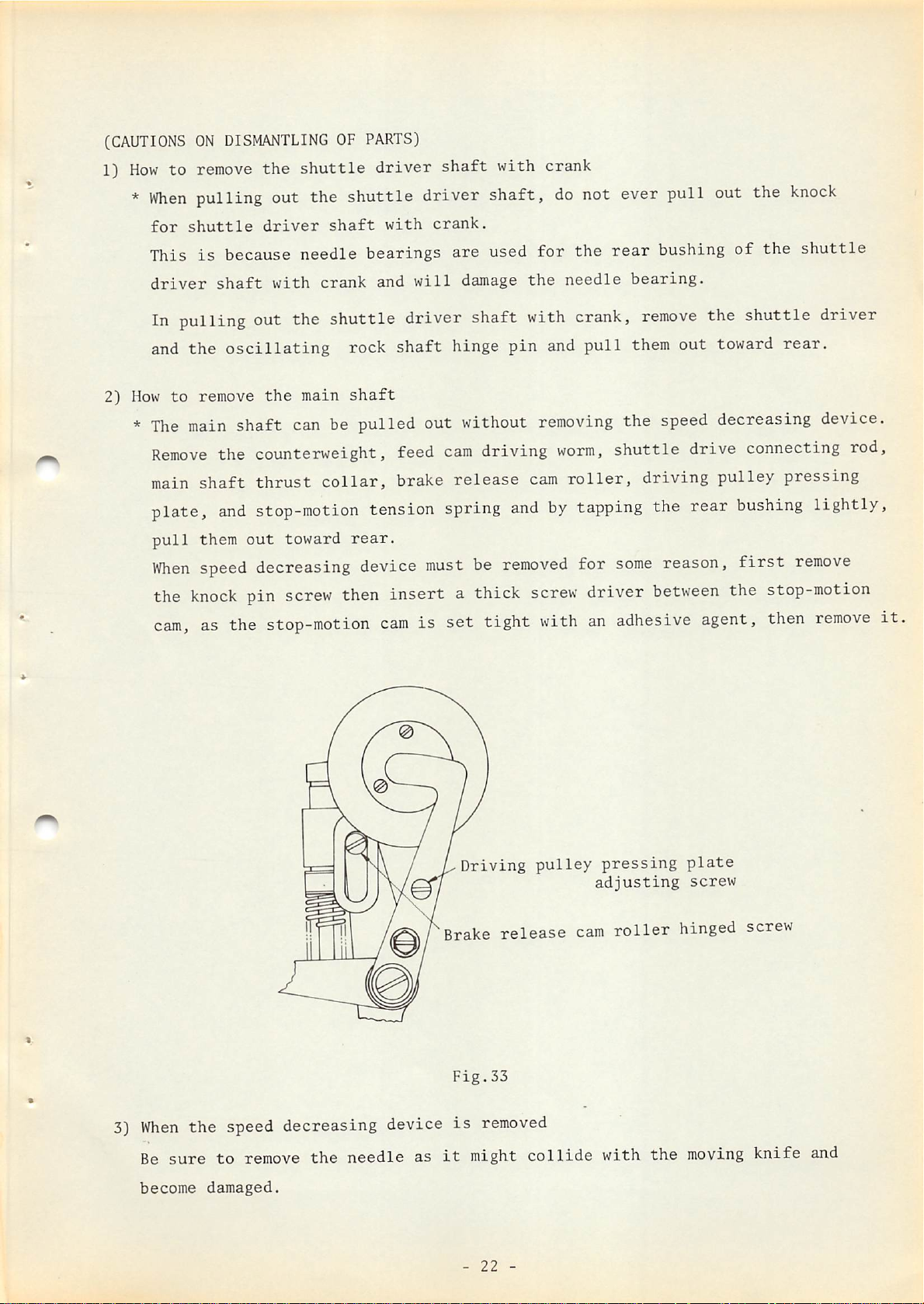
(CAUTIONSONDISMANTLINGOFPARTS)
1}
Howtoremove
*
When
pulling out the shuttle driver shaft,
for
shuttle
the
driver
shuttle
shaft
driver
with
shaft
crank.
with crank
do
not ever pull out the
knock
2)
This
driver
is
because needle bearings are used
shaft
with
crank
and
will
damage
for
the
the
needle
In pulling out the shuttle driver shaft with crank,
and
the
How
*
The
Remove
main
plate,
pull
When
the
cam,
oscillating
to
remove
main
the
shaft
can
the counterweight, feed
shaft
them
speed
knock
thrust
and
stop-motion
out
toward
decreasing device
pin
screw
as the stop-motion
main
rock
shaft
shaft
hinge
be pulled out without
cam
driving
collar,
tension
rear.
brake
must
release
spring
be
then insert a thick
cam
is
set
tight
pin
and
removing
worm,
cam
and
by
removed
screw
with
roller,
tapping
for
rear
bushing
bearing.
pull
remove
them
the
speed
shuttle
the shuttle driver
out toward
decreasing device.
drive connecting rod,
driving pulley pressing
the
rear
some
driver
an
adhesive agent, then
reason,
between
the stop-motion
of
the
rear.
bushing
first
shuttle
lightly,
remove
remove
it
3)
When
Be
sure
become
the
speed decreasing device
to
remove
damaged.
the
needle
as
Driving
Brake
Fig.33
is
it
might
-
removed
22
pulley
release
collide
-
pressing
adjusting
cam
with
roller
plate
screw
hinged screw
the
moving
knife
and
Page 26

(HOWTOTIGHTEN
1)
How
to
eliminate
THE
RATTLE)
the
rattle
of
the
Feed
main
cam
0
shaft
2)
*
When
the
direction
greatly
thrust
toward
* Most
* After
tension
How
to eliminate the
wheel
*
When
tension
of
the
To
eliminate
affected.
collar
the
appropriate
tightening
releasing
rattle
releasing
main
Main
shaft
thrust
machine becomes
of
the
main
shaft,
To
tighten
toward the
arrow
direction.
rattle
the
rattle,
timing.
rattle
is
formed
shaft.
this
on the feed
timing
rattle,
collar
Fig.34
old
arrow
(Fig.34)
toward
of feed
will
remove
and
rattle
the feed
and
eliminate
direction
the
main
re-adjust
cam
cam
be
greatly
the
begins
and
while
shaft
the feed
driving
driving
affected
to
be formed toward
the tension releasing timing
this
rattle,
rotating
direction
cam,
worm
worm
and
parts,
just
move
the feed
should
stitch
feed
in
the
the
the
shaft
will
the
main
cam
be 0.01'^0.04mm.
regulating
cam
driving
feed and
case
shaft
strongly
cam
the
of
the
be
and
worm
rattle
driving
Then,
*
the
between
shaft
worm
of
be
cover
and
rotate
of
the
loosen
worm.
press
the
arrow
will
the
eliminated.
direction
the
will
move
main
the
down
feed
main
not
shaft
top
2
become
toward
(Fig.35)
surface
screws
the
cam
shaft
and
of
feed
driving
so
that
and
wrong.
the
the
of
cam
rear
rattle
the
the
worm
the
the
frame
feed
shaft
toward
relation
feed
Then,
bushing
will
-
23
cam
and
cam
the
-
r1
1
—
0
Fig.35
X
w
])
J
Page 27
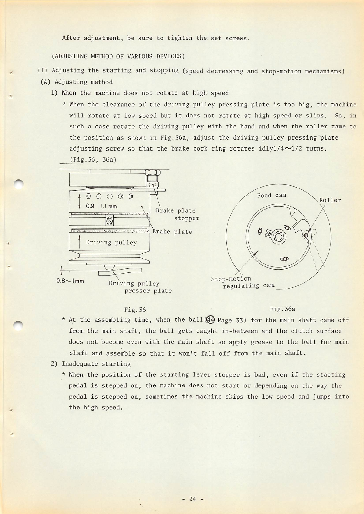
After
adjustment,
be
sure
to
tighten
the:
set
screws.
(ADJUSTING
(I)
Adjusting
(A)
1)
Adjusting
When
*
When
will
suchacase
the
adjusting
(Fig.36,
i:
METHOD
the
method
the
the
rotate
position
(D
9 I.I
machine
OF
starting
does
clearance
at
low
rotate
as
screw
36a)
O O O 0
mm
VARIOUS
and
not
of
speed
the
shown
so
that
X Brake
DEVICES)
stopping
rotate
the
driving
but
driving
in
Fig.36a,
the
brake
Brake
(speed
at
it
does
pulley
plate
stopper
plate
decreasing
high
pulley
not
adjust
cork
speed
with
ring
pressing
rotate
the
the
driving
rotates
and
at
hand
stop-motion
plate
high
is
speed
and
when
pulley
idlyl/4^1/2
Feed
cam
too
or
the
pressing
mechanisms)
big,
the
slips.
roller
plate
turns.
Roller
machine
So,
in
came
to
0.8'^'
*
2)
Inadequate
*
I
imm
At
flrrom
does
shaft
When
pedal
pedal
the
the
high
Driving
pulley
Driving
assembling
the
not
the
is
is
main
become
and
shaft,
assemble
starting
position
stepped
stepped
speed.
pulley
presser
Fig.36
time,
even
so
of
on,
on,
plate
when
the
ball
with
the
that
it
the
starting
the
machine
sometimes
Stop-motion
regulating
the ball(@Page
gets
main
won't
the
caught
shaft
lever
does
machine
fall
so
off
stopper
not
in-between
start
skips
33)
apply
from
for the
grease
the
is
bad,
or
depending
the
cam.
Fig.36a
and
main
low
main
the
to
even
speed
clutch
the
shaft.
if
on
shaft
ball
the
the
and
came
surface
for
starting
way
jumps
off
main
the
into
-
24
-
Page 28

Adjust
the
position
of
the
starting
lever
stopper
so
that
at
the
low
speed
sewing,
the
stop-motion
to
function
clearance
regulating
effectively.
between
cam
roller
(Fig.37)
the
stop-motion
comes
to
lmm(
Starting
regulating
3/64'*)
lever
cam
to
enable
stopper
and
the
the
stopper
* When
so
the
clearance
the
roller
they
might
or
make a "bump-bump"
make
(Fig.38)
the
is
big
catch
clearance
between
at
each
the
stop-motion
other
noise
to
O.Smm.(1/64")
Fig.37
the
stop-motion
at
starting
sometimes,
time,
time
Stop-motion
regulating
latch
cam
groove
and
Fig.38
-
25
-
•Fig.
Stop-motion
38»
cam
Page 29

*
If
an
unusual
torque
should
bear
on
the
machine
during
running, the
machine
might
speed
machine.
3)
When
*
When
the brake clutch
stop
running
running.
the
machine
the floating
when
Adjust
does not run
the
the
amount(rise)
becomes
inadequate
So, adjust the brake plate stopper so
running
amount
brake cork ring fore
idly
stop-motion
When
of driving
machine
If
the
or at
of
all
high
parts
speed
even.
and
whenitreaches the
time.
the
brake
is
brake
cork
and
af
running
cork ring
ring
stop-motion
at
low
running
And,
aft
extreme
is
speed.
is
too far
low
speed
machinesothat
at
low
of the
running
speed
brake
and
that
is to
no
unusual
plate is
slips.
the floating
comesto1.5mmCl/16")
after
so
that
observed to be stopping
time, the
that,
as
shown
the stop-motion latch begins to rotate
outer
worn
rim
of the stop-motion
brake
is perfectly functioning
out to be adjusted,
be
switched
torque
too
big, the biting of
amount
and
make
over
is
borne
at
either
the floating
to
by
in Fig.38', adjust the
cam
at the
momentarily
at the
start
and
exchange
it
with a
high
the
idle
the
new
one.CFig.36,
*
In
height
*
Whem
will
case the
oil
not
brake
of
the spring to
and
grease
enter
into
to driving clutch also in
(Note)
*
slipping
Do
not use thinner or trichlorothane as they
brake
When
driving clutch
In such a
the
main
sound.
cork.
the returning
does
case,
shaft
and
the driving belt is too strong,
the
tension
Generation of unusual noise
*
When
the clearance of the pulley pressing plate
of
the
Fig.38')
spring
etc. are sticking to the
is
8mmC5/16")
low
speed, so
too
which
weak,
case
it
or exchange
wipe
if
too will
them
brake
off
slip,
it
with a
cork
with alcohol. This holds
oily matter sticks to
impede
power
not separate
either
of the spring for the the
and
the
machine
exchange
the
spring
or
main
will not rotate at
insert
adjust the strength of the spring. Also,
sometimes
belt.
the spring will not return,
is
too narrow, the driving
so either adjust the
new
one.
ring
it
might
it,
it
produces
slip
the function of the
shaft is
weak,
low
a washer
into
if
the hole
the tension of
so
true
the
speed.
adjust
and
of
a
t
clutch
bearing
will
at high speed,
will
to
slip
generate
enter
during
refer
out.
at
low speed running, causing the
As a
idle
to 1) of
result,
running.
this
-
the
Therefore,
chapter
26
-
ball
and
will-be
when
make
outer
bruised
the
proper adjustment.
ring
and
machine
inside
unusual
is
to
the
be
noise
run
Page 30

*
Unusual
When
of
like
To
the
*
The
*
The
correct
the
cork
a
squeaky
cause
cause
noise
surface
this
is
of
of
from
of
small
sound
this
this
unusual
the
cork
the
and
generates.
sound
sound
cork
when
at
at
sound,
of
the
starting
starting
stopping
remove
clutch
is
time
time
the
is
oscillating,
stopped,
is
is
723
cork
and
sometimes
38
of
rof
with
the
Fig.39-1.
Fig.39-1.
a
sand
contacting
an
unusual
paper
make
area
noise
the
contacting
* Even
the
Use
grease
* Even though
timing
main
stop-motion
bruised
refer
5)
Generation
*
If
the
pulley
refer
and
is
big
surface
if
dust
gets
ball
will
of
lithium
the
is
such
shaft
is
cam
and
the
to
page 26 3) and make
of
unusual
floating
and
at
to para.3) of
make
proper adjustment. This
and in
wider.
into
be
bruised.
group
stop-motion
that
the
trying
to
is
interlocked
sound
of
heat
amount
high speed
this
this
case
the
grease
So
consistency
hook
brake
rotate
speed
proper
of
the
running,
chapter on
refer
or
be
careful
is
caught
plate
at
to
is
low
the
decreasing
adjustment.
brake
is
this
"When
also
to
the above
the
quality
when
No.2
biting
speed,
assembling.
for
this
in
the
into
it
hook and thus
device
not
uniform
unusual
heat
the machine does not run
happens
when
para,
of
grease
purpose.
stop-motion
the
cork,
can
not
rotate
the
ball
becomes
at
both
generates.
the
oscillation
on "Unusual
has
loud.
idle
become
cam,
then
even
because
bearing
In such a
running
In such a
noise
if
will
at
of
from
inferior,
the
if
the
the
be
case,
of
the
case,
low
speed"
the cork
the cork"
and
*
If
hard
generates
very
capacity
*
How
Refer
6)
Stop-motion
correct
too
much
grease(high
also.
lightly
of
to
apply
to
the
sound
this
defect.
grease
consistency
In such a
to
the
the
driving
grease
following
is
is
outer
big
poured
ring
ring
chapter
(Fig.39)
into
the
number)
case,
apply grease
inside
long holeCS
on "Assembling
ball
is
the
bearing
used
ball
places).
for
at
assembling
of
lithium
decreasing
time,
group consistency
the
unusual
bearing and apply about 1/5
the
speed
decreasing
unit".
speed
heat
or
No.2
of
-
27
-
Page 31

* When
the
clearance
between
the
stop-motion
lever
and
the
stop
ring
rod
latch
is
small,
by
the
ring
*
Correct
cam
so
stop-motion
*
Also,
into
para.3)
adjustment.
the
stop
stop-motion
rod
latch
stop-motion
that,
at
at
the
low speed
above on
link
and
and
the
at
the
the
same
end
of
step,
"When
Stop-motion
rod
latch
generates
stop-motion
timing
last
stitch,
time
sewing,
thus
the
into
hits
sound,
lever
can be
the
as
obtained
the
it
passes
high
generating
machine does
goes
action
the
stop-motion
so
to
stop
ring
the
speed
adjust
14mm(9/16").
by
adjusting
stop
running
rod
lever
the
clearance
latch
ring
suddenly
the
rod
shock sound. In such a
not
run
at
low
speed"
Stop-motion
cam
by
the
stop-motion
cam
part
latch.
stops
case,
and make
shock
between
enters
without
refer
produced
the
stop
regulating
into
entering
to
the
proper
Stop-motion latch
Fig.39
Stop-motion
lever
-
28
-
Page 32

(B)
Assembling
the
speed
decreasing
unit
This
of
chapter
parts,
refer
treats
to
only
the
the
parts
assembling
list
for
order,
LK-280
and
so
for
the
construction
names,
construction
diagram.
etc,
that
grease
to
ring.
grease
much
that
balls
Cautions
all
and
grease
carefully.
there
Assembling
ordei
1.
2.
3.
1.
Note
Apply
Refer
thrust
Apply
capacity
2.
If
N)
CO
3.
too
so
watch
Verify
in
the
on
parts
to
Fig.39-1
the
are
needle
to8long
set
the
is
are
or
inside
assembling
concentric.
bearing
for
inserting
holes
balls.
applied,
no
dust
and
outside
to
heat
or
parts
about
foreign
rings.
the
will
1/5
generate,
matter
1.
2.
Cautions
Verify
the
If
something
with
balls
new
that
and
ones.
on
dismantling
there
inside
is
wrong,
are
no
and
exchange
bruises
outside
on
rings.
them
1.
Put
the
2.
3.
pushing
clipped
Watch
Verify
through
lower
in-between
out
that
the
for
end
push
the
all
shaft)
parts
on
top
of
in(2) . ( ^
byaplier).
balls
which
are
the
base
and
and
@
may
jump
concentric.(Pass
may
out.
by
be
them
1.
By
pushing
(T)
and by gouging between
Q) and (y) , with a screw
2.
remove
Watch
jump
out
out.
©•
for
the
balls
driver
which
might
Page 33
♦
•>
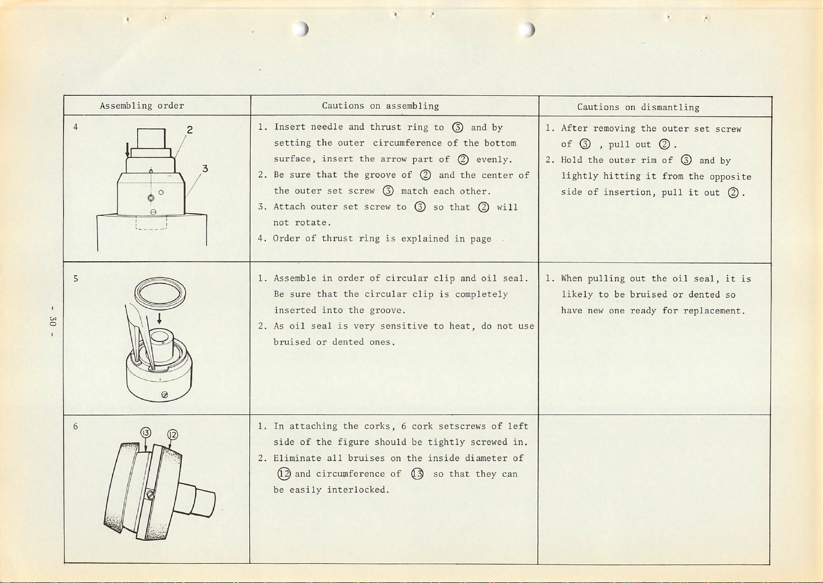
Assembling
C/l
o
order
1.
Insert
setting
surface,
2.
Be
sure
the
outer
3. Attach
not
rotate.
4.
Order
1.
Assemble
Be
sure
inserted
2.
As
oil
bruised
Cautions
needle
the
insert
that
outer
of
thrust
in
that
into
seal
or
set
dented
on
and
thrust
outer
circumference
the arrow
the
groove
screw
set
screw to © so
ring
order
is
the
the
very
of
circular
groove.
sensitive
ones.
assembling
ring
part
of
© and
match
is
explained
circular
clip
to
@ and by
of
of
^ evenly.
each
that
in
clip
is
completely
to
heat,
the
the
other.
page
and
bottom
center
©
will
oil
do
not
seal.
of
use
Cautions
1.
After
of
removing
© )
2. Hold the
lightly
side
of
1.
When
pulling
likely
have
new
on
poll
outer
hitting
insertion,
out
to
be
bruised
one
ready
dismantling
the
outer
out © .
rim
of
it
from
pull
the
for
set
© and by
the
it
out
oil
seal,
or
dented
replacement.
screw
opposite
©.
it
so
is
1.
In
2.
attaching
side
Eliminate
and
be
easily
of
the
corks,
the
figure
all
bruises
circumference
interlocked.
should
on
of
6
the
cork
be
setscrews
tightly
inside
so
that
screwed
diameter
they
of
left
in.
of
can
Page 34

Assembling
Cautions
on
assembling
Cautions
on
dismantling
1. Apply grease
2.
Assemble
inserted to the hole of
3.
Apply
of 0
plenty of grease to 3 places of the
(figu^®
to
the
so that the
shows
needle.
f£b
part of 0 will be
0.
the
back
of 0 •
4. After assembling, verify that 0
1.
2.
Insert
Apply
the
cDa
part
of
©
grease to the needle.
to
side)
and
moves
the
holeof© -
groove
3 holes
smoothly,
1.
When
2.
® is to
caught
sure
Be
means
shaft.
to the
that
sure to verify that
of the spring
it
be
inserted, ® is liable to
hinged
is
part of the shaft, so
concentric.
and
10
returns
smoothly
balls inside the
be
be
by
main
Page 35

HOW
TO
*
REFILL
Refill
THE GREASE
the
grease
at
least
once
in2years.
* Use
* How
NAMES
ESSO
SHELL
grease
to
Remove
up
the holes with grease
grease.
Repeat
speed
OF GREASE TO BE USED
kerosene
kerosene
decreasing
of
refill
@
(Fig.54).
this
lithium
and
after
process
device.
Listan
Albania
family
removing
of
consistency
the
spring
and
push in hard with
3 times and about 2
2.
Beacon
2
CC
No.2.
and
of
balls in
screw
grease
the
for
will
main
refilling
be
refilled
shaft,
the
fill
into
the
-
32
-
Page 36
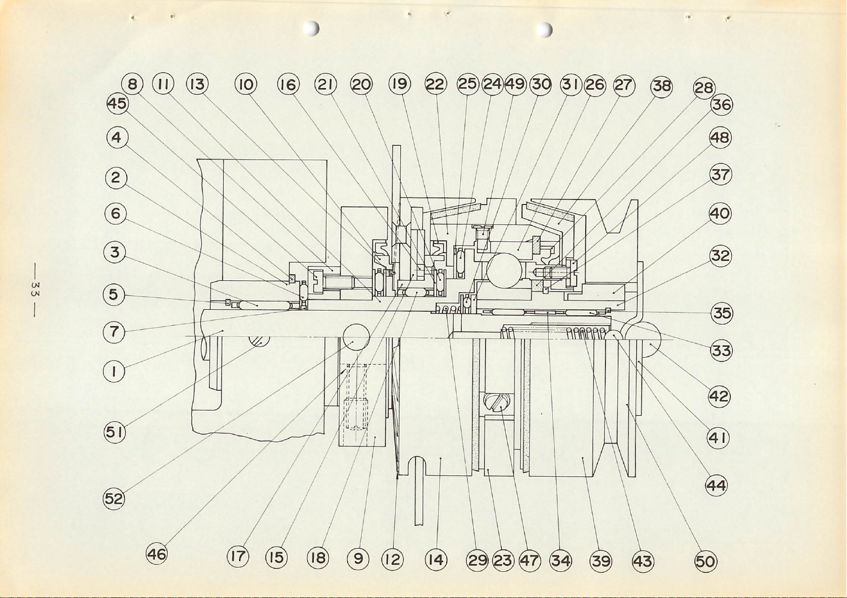
w
Ui
Page 37
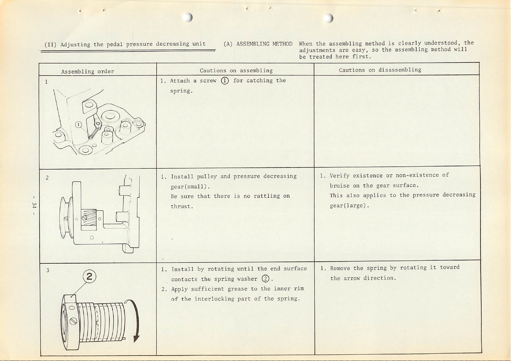
(II)
Adjusting the pedal pressure decreasing
— -
unit
(A)
ASSEMBLING
METHOD
When
the assembling
adjustments
be
treated
are
here
easy,
first.
method
so
is
clearly
the
assembling method
understood, the
will
Assembling
order
1.
Attachascrew
spring.
1.
Install
gear(small).
Be
sure
thrust.
Cautions
pulley
that
on
assembling
^ for catching the
and
there
pressure
is
no
decreasing
rattling
on
1.
Verify
bruise
This
gear(large).
Cautions
existence
on
also
on
disassembling
the
gear
applies
or
non-existence
surface.
to
the
pressure
of
decreasing
1.
Install
by
rotating
until
contacts the spring washer (2).
2. Apply
of
sufficient
the
interlocking
grease
part
to
tUJdd.
of
the
the
the
end
inner
surface
spring.
rim
1.
Remove
the
arrow
the
spring
direction.
by
rotating
it
toward
Page 38

on
Assembling
4 (2
order
1.
Assembling
sketch.
2. After
matching
by the figure,
the
arrow
3.
Apply
rim
sufficient
of
Cautions
in
the
direction.
except
on
assembling
order
the
end
assemble
grease
the
as
shown
by
the
above
of spring with ^ as
by
rotating @
to
the
gear
wheel
outer
part.
toward
and
inner
shown
1.
When
decreasing
it
Cautions
removing
toward
on
dismantling
the
gear(large),
the
arrow
pressure
direction
rotate
also
1.
Set
it
Knock
pin
2.
3.
and
insert
Hammer
Remove
pin
of
to
in
scratch
knock
.
as
.
from
shown
pins
in
to2places.
the
hole
the
above
part
of
sketch
knock
1.
To
pull
out
the
screw
pull
direction
and
it
out
the
knock
out
pin,
by
tapping @ lightly,
toward
of
the
first
loosen
the
arrow.
pull
the
reverse
Page 39

V F
Assembling
o^
order
1.
2.
1.
2.
Wind
lever(rear
R
part
toward
Verify
Adjust
position,
rotate
time
toward
to
such
sketch.
After
the
tightening
incorrect.
the
and
the
if
as
idly
position
the
Cautions
c£h
part
side
set
it
arrow
the
lever
follows:
the
pressure
and
adjust
the
arrow
adjustment,
is
on
assembling
which
in
the
to
the
direction.
moves
When 8
decreasing
direction
of
No.9-B
tighten
inadequate,
is
caulked
figure),
lever
smoothly.
comes
7
and
or
to
catch
by
push-opening
to
gear(large)will
8
at
so
that
C,
as
shown
the
9
the
phase
the
it
No.9-A
the
same
2
screw.
becomes
to
comes
in
the
the
If
Cautions
on
dismantling
3.
Rotate
and
decreasing gearClarge)
touching
means
re-adjustment
the
verify
the
pulley
if
it
with the hand.
9
toward
is
No.9-B and C
must
be
stopped
is
are
made.
the
normal
when
rotating
If
defective,
direction
the pressure
idl>^
it
is
wiggling,
so
by
it
Page 40

CB)
ADJUSTING
1)
When
[i)
METHODS
the
work
Verification
The
correct
clamp
of
foot does not
phase
phase under
of
the
work
various
condition as
parts
properly
shown
Phase
of
various
parts
[ii) If
[iii)
in Fig.41 should be as
there
do
not operate
with hexagonal
is
no
is
given,
carefully.
Verification
When
lifting
clearance,
and
return
is a
clearance.
gear
returning
lever
the
sometimes
properly.
clearance
properly,
holes
If
noise
of
work
spring
is
too
reaction
the
work clamp
shown
between©
so loosen
and
adjust
too
much
will
emanate, so watch
clamp
of
the
weak
or
of
in Fig.40.
so
thrust
foot
lifting
work clamp
there
the
lever
foot
does
and
the
that
is
® ,
screw
rattle
a
is
not
there
lever
foot
dull
they
^
Work
clamp
foot
^ lowering shaft
^ Decreasing
Cy
Decreasing
©
clutch
latch
inner
sleeve
^ Decreasing outer
Cy
sleeve
Fig.41
Work
lifting
Work
lifting
clamp
Work
lifting
clamp
lever,
foot
lever
clamp
foot
foot
lever
guide
returning
plate
Fig.40
spring
-
37
-
Page 41

2) When
(i)
In
*
noise
case
Verify
generates
of
gear
the
respective
noise
(
thrust
rattle
of
large
and
small
gears.
When
*
Also,
generates.
(ii)
In
*
Verify
If
3)
Other
* Following 3
of
Ci) Large
* Diameter
new
(ii)
Unusual
*
When
the
thrust
when
case
of
that
this
malfunctions
these
relationship
malfunctions
gear.
of
one.
condition
the
inside
rattle
dust
or
foreign
So
watch
tearing
all
components conform
carefully.
noise
is
malfunctions
is
Abrasion
shaft.
of
of
If
clutch
diameter
is
big,
matter
inadequate,
can be
very
slight.
interlocking
it
becomes
spring
became
gear
noise
is
stuck
to
tKe
a
tearing
considered
part
less
over
18.9^orwhen
generates.
on
the
relationship
noise
but
it
of
spring.
than
19.2
gear
emanates.
is
opined
exchange
the
surface,
of
No.Q-A'vC.
that
spring
gear
occurrence
it
with
power
noise
a
is
weakened,
exchange
it
with
a new
one.
-
38
-
Page 42

(Ill)
1)
Adjusting
Matching
the
the
moving
thread
trimming
knife
device
* The
*
correct
At
the stop-motion time, the clearance
and
the
When
this
position
end
of
position
screw and by moving
the
correct
position.
Thread
connecting
the
of
the
needle
is
incorrect,
the
(Fig.42)
trimming
moving
hole
thread
screw
0
0
knife
should
is
as
between
be
1,5mm(l/16").
follows:
the
loosen the thread trimming
trimming
lever
lever(small)
Thread
Moving
trimming
knife
tail
back and
link
end
of the
lever
forth
lever(small)
moving
knife
connecting
adjust
to
2)
How
The
last
or
when
too
small
decreasing
device
to
adjust
correct
stitch
thread
or
are
the
thread
movement
but
if
the
trimming
for
any
device
dimensionally
and
of the
moving
is
other
verify
trimming
moving
knife
not
reason
if
correct.
Fig.42
device
knife is
activates
performed
if
unusual
all
the
due
related
performed
between
to
the
stroke
defect
occurs,
components
between
the
low
of
of
215°~'357°
speed
the
remove
the
sewing
moving
the
thread
of the
area
knife
speed
trimming
is
-
39
-
Page 43
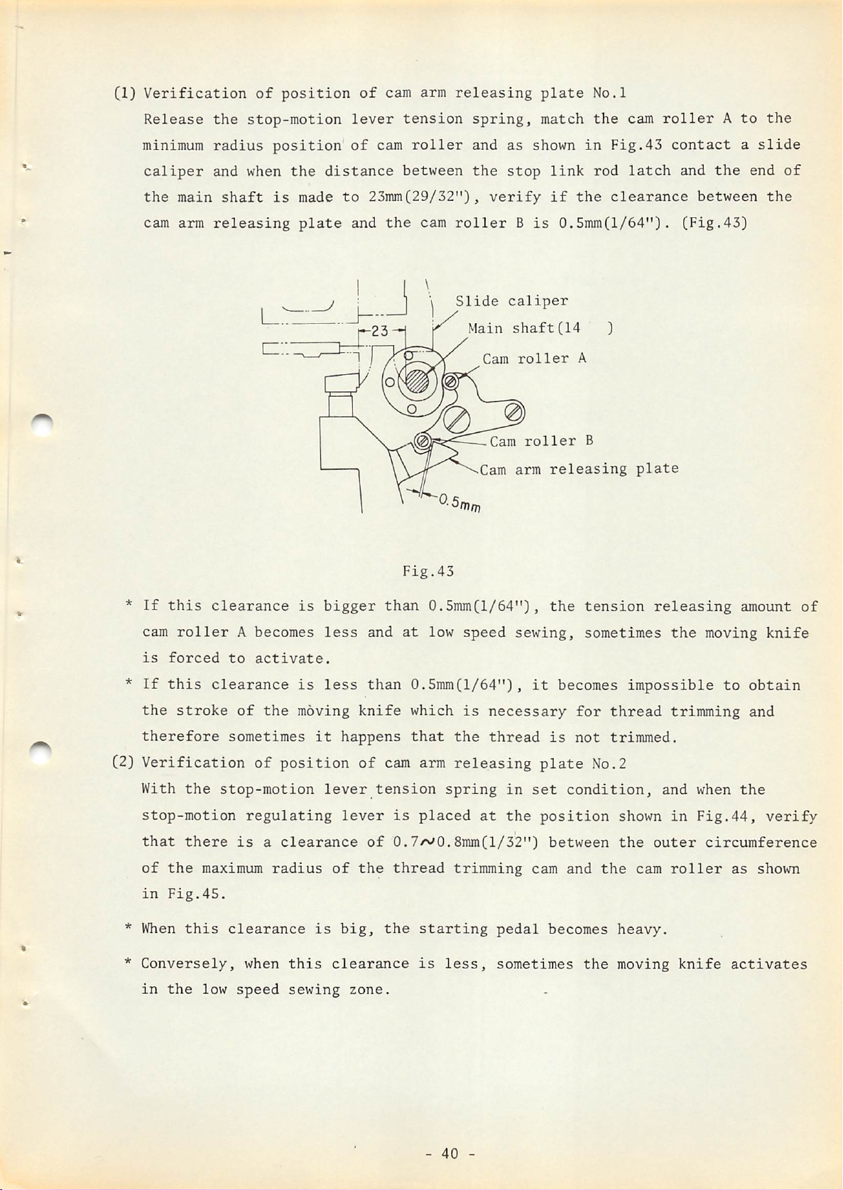
(1)
Verification
of
position
of
cam arm
releasing
plate
No.l
Release
minimum
caliper
the
main
cam arm
the
stop-motion
radius
and when
shaft
releasing
l:
position
the
is
made
plate
lever
of
distance
to
23mm(29/32"),
and
cam
the
tension
roller
between
cam
m
spring,
and
the
roller
Slide
Main
Cam
Cam
as
stop
verify
B
caliper
shaft(14
Cam
arm
match
shown
link
if
is
0.5mm(l/64")•
roller
roller
releasing
in
the
A
B
the
Fig.43
rod
clearance
cam
latch
plate
roller
contact
and
(Fig.43)
A
the
between
to
a
slide
end
the
of
the
*
If
cam
is
*
If
this
the
therefore
(2)
Verification
With
stop-motion
that
of
the
in
*
When
*
Conversely,
this
roller
forced
stroke
the
there
Fig.45.
this
clearance
A becomes
to
clearance
of
sometimes
stop-motion
regulating
is
maximum
clearance
when
activate.
the
of
position
a
clearance
radius
is
is
moving
it
is
this
bigger
less
less
and
than
knife
happens
of
lever
lever
of
of
the
big,
clearance
Fig.43
than
0.5mmCl/64"),
at
low
speed
0.5mm(l/64")^
which
that
cam
arm
tension
is
placed
0.7w0.8mm(l/32")
thread
the
starting
is
is
the
releasing
spring
trimming
less,
sewing,
necessary
thread
in
at
the
pedal
sometimes
the
it
becomes
is
plate
set
condition,
position
between
cam
and
becomes
tension
sometimes
impossible
for
thread
not
trimmed.
No.2
shown
the
the
heavy.
the
moving
releasing
the
trimming
and
in
outer
cam
roller
moving
to
when
Fig.44,
circumference
as
knife
activates
amount
knife
obtain
and
the
verify
shown
of
in
the
low
speed
sewing
zone.
-
40
-
Page 44

0.7'^0.8mm
Fig.44
All
of
above
to
prevent
to
inadvertant
The
cam
arm
and adhesive agent
take
it
out.
related
dimensions
malfunctions
inadequate dimensions, exchange
releasing
Also,
to
when
plate
produce
emergency measure must be
latch
This
purely
from 3mmCl/8")
is
an emergency measure
as
an
emergency
to
measure
are
carefully
but
should any
is
set
to the stop-motion lever by screw,
correct
the
knife
taken,
activates
adjust
4mmC5/32"), as
to
prevent
only.
Fig.45
checked
malfunctions
the
dimensions, so
within
the
clearance
shown
the
in
Fig.46.
knife
Stop-motion
from moving
at
the
occur
in
time
the
of
assembling
open market due
stop-motion lever(B26012800AO)
it
is
the
low
between
regulating
roller
knock
very
difficult
speed zone and an
the
but
shaft
stop
consider
lever
link
nut
pins
to
rod
this
Fig.46
-
41
-
Page 45

C3)
Verfication
*
Verify
When
this
if
of
tension
the
spring
tension
is
spring
spring
not
set
for
knife
for
knife
properly
driving
driving
or
worn
out
rod
rod
is
and
functioning
the
necessary
normally.
spring
CIV)
pressure
it
is
trimming
Therefore,
Adjusting
* As
shown
of
low
latch
When
trimming,
action
Therefore,
* The
regulating
shaft
of
impossible
becomes
the
in
speed
should
this
of
position
to
right
4.53kg
to
inadequate.
it
is
very
position
Fig.46,
sewing
be
3mm(l/8").
relative
inadequate
the
safety
verify
of
the
lever
roller
and
+
0.5kg(overall
obtain
important
of
the
correct
zone,
position
movement
device,
the
correct
stop-motion
shaft
left
within
normal
the
stop-motion
the
is
etc.
length
function
to
verify
position
clearance
wrong,
of
speed
occur.
position
lever
nut
and
the
area
99mm(3-S7/64"))
of
the
the
condition
lever
of
the
between
such
malfunctions
decreasing
of
this
can be
move
of
adjusted
the
the
moving
stop-motion
the
stop-motion
components
stop-motion
by
stop-motion
long
groove.
can
knife
of
the
lever
as
inadequate
and
lever.
loosening
regulating
If
not
be
and
tension
at
cam
inadequate
it's
obtained,
thread
spring.
the
time
and
the
stop
thread
stop-motion
roller
moved
(V)
toward
cam
and
When
Adjusting
*
The
standard
so
that
of
the
However,
hole
screw
the
the
you
the
when
bobbin.the
on
the
and
arrow
do
when
adjust
direction,
stop
link
this,
thread
adjustment
the
last
the
upper
by
rod
leave
the
tension
is
stitch
No.2
tension
following
left
side
raising
the
clearance
latch
becomes
stop-motion
release
for
the
needle
disc
phenomenon
of
the
the
tension
thread
thread
will
cam
between
wider.
lever
tension
loop
be
occurs,
cover,
release
tension
has
released.
insert
loosen
lever
the
stop-motion
spring
release
slipped
a
the
up
lever
screw
tension
and
in
out
driver
down.
regulating
the
set
to
be
from
release
(Fig.47)
condition,
set
the
from
comer
the
hinge
-
42
-
Page 46

The
standard
length
of
the
needle
thread
is
35~40mm(l-3/8"-«^l-37/64")
No.
1
2
3
4
Condition
needle
Too
thread
long
Disarranged
Jumps
short
Breaks
up
length
in
midway
Tension
Tension
of
in
Tension
Raise
Lower
release
release
release
hinge
it
it
lever
latch
Tension
Lower
Lower
Raise
Raise
lever
screw
release
it
it
it
it
Tension
tripping
lever
release
segment
link
Fig.47
Tension
Adjusting
for
tension
release
screw,
release
leverfAQ.
latch
\
Outer
Fig.48
-
43
rim
of
feed
-
cam
Page 47

* Adjust
the
end
of
the
tension
release
latch
by
means
of
the
tension
release
(VI)
latch
a
end
*
If
release
Adjusting
1)
Adjusting
*
If
shorter
adjusting
clearance
and
the
the
adjustment can not be
lever,
the
the
screw so
of
0.2~0.3mmCl/I28"'v
feed
adjust
feed
bartacking
the hinge nut
and
if
it's
that
cam.
components
is
(Fig.48)
by means
length
loosened and
lowered
during the running of the machine,
made
of
down,
1/100")between
within
tension
raised
it
the
adjusting
release
up, the bartacking length
will
become
the
link
longer.
tension
area
tripping
(Fig.49)
of
there
release
the
tension
segment.
will
will
latch
become
be
2)
Adjusting
*
Loosen
spanner
of
If
and
the
bartacking
the feed regulator
into the
the
bartack.
it's
rotated
if
it's
rotated
thickness
hexagonal
zoward
left
toward
Fig.49
knob
nut
and
patt of the
direction,
right,
it
by
inserting a double face
feed
the
becomes
Feed
knob
L/
Feed
knob
Longer
Hinge
regulator
bartacking
thinner.
regulator
nut
regulator
nut
knob,
adjust the
thickness
(Fig.50)
14mm(9/16")
thickness
becomes
thicker
-
44
-
Fig.50
Page 48

*
When
3)
Adjusting
*
With
the
the
adjustment
the
left
large
bartacking
is
and
completed,
right
indicating
machine
be
of
sure
to
tighten
linesCFig.51)
42
stitches,
the
the
26th
knob
stitch
nut.
comes
to
the
center
that
matching
(For
*
If
driving
feed
adjust.
*
The
joint
will
of
the
bartacking
they
across
standard
is
be
Feed
Feed
driving
the
stitches,
matching
with
point
each
machine
are
not
matched
stud(left)
connecting
concentric
S0mm(l-31/32")
small
across
driving
across
stud(left)
and
if
connecting
so
of
other.
of
with
set
screw
driving
between
but
it's
connecting
studCleft)
set
rotate
the
work
28
stitches,
each
and by
stud(left),
the
please
shortened,
screw
the
clamp
other,
inserting
shuttle
note
the
machine
foot
18th
loosen
rotate
that
stitches
to
stitch
a
driver
if
and
the
bar
it's
the
the
is
feed
into
it
shaft
will
26th
stitch
center
the
center)
across
the
to
right
with
lengthened,
become
and
of
the
connecting
open
and
crank
the
big.
verify
needle
hole
left
and
stitches
(Fig.51)
of
and
the
are
the
ball
4)
Adjusting
* Be
work
sure
to
clamp
the
Feed
fore
verify
foot
across
and
that
or
the
driving
Fig.51
aft
the
feed
arm
indicating
needle
plate.
Work
clamp
base
lines(Fig.52)
is
dropping
foot
set
screw
Shuttle
with
uniformly
mounting
crank
driver
shaft
concentric
without
hitting
Fig.52
the
Feed
plate
set
screw
A
-
45
-
Page 49
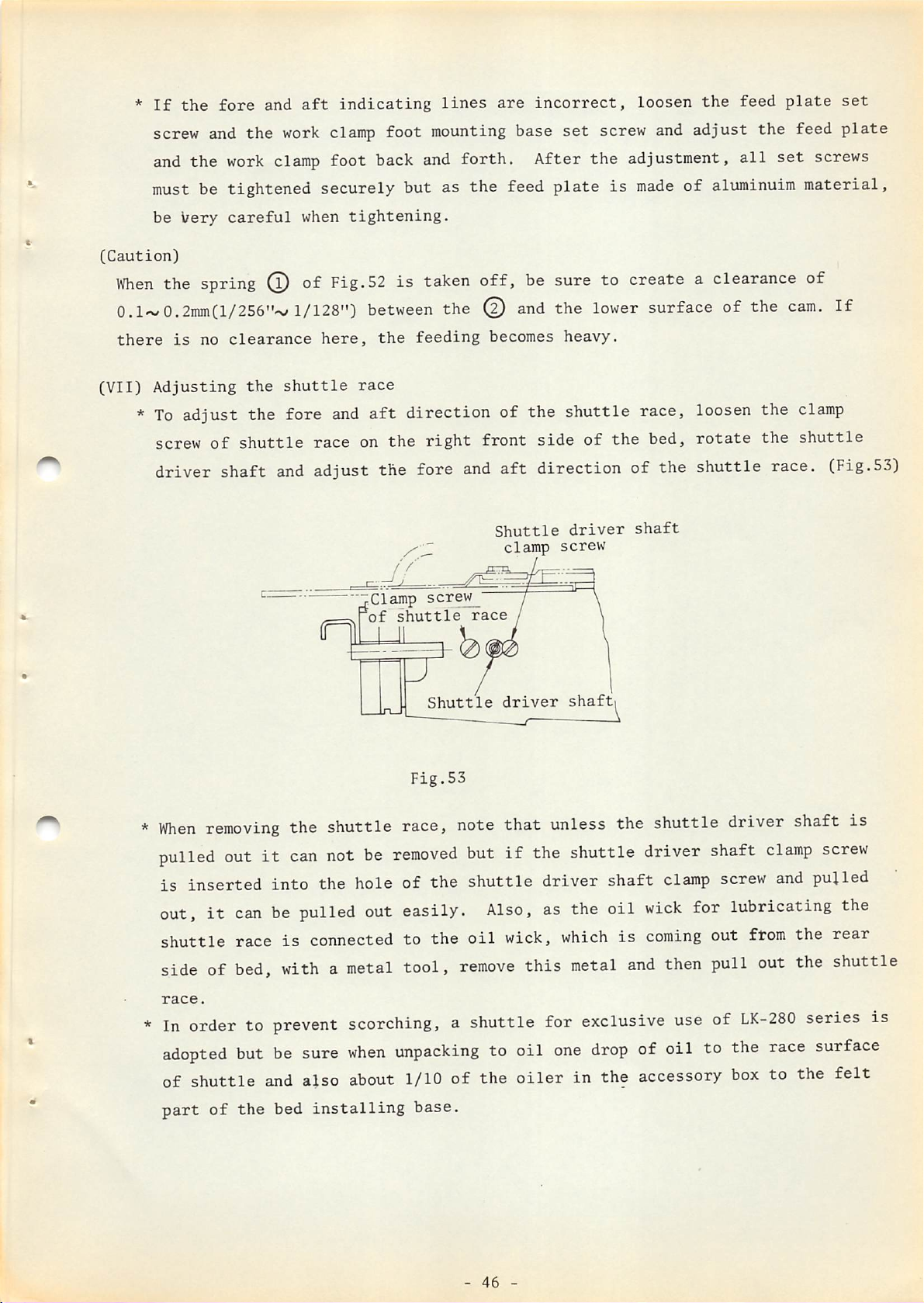
*
If
the
fore
and
aft
indicating
lines
are
incorrect,
loosen
the
feed
plate
set
screw and
must be tightened
[Caution)
When
and
the
be
Very
the spring
the
work
work clamp
careful
when
(l)
of Fig.52 is taken off, be sure to create a clearance of
0.1'S'0.2inm(l/256"'N/1/128")
there
(VII)
is
no
Adjusting
*
To
adjust the fore
screw
of
driver shaft
clearance
the
shuttle
shuttle
and
race
adjust the fore
clamp
foot
back and
securely
tightening.
between
here,
and
the
race
aft
on
foot mounting base
but as
the @
feeding
forth.
the
After
feed
and
becomes
direction of the
the
right
and
front
aft
Shuttle
clamp
side
direction of the shuttle race. (Fig.53)
set
the
plate
the
lower
heavy.
shuttle
of
driver
screw
screw and
adjustment,
is
made
adjust
of
surface of the
race, loosen the
the
bed,
shaft
all
aluminuim
rotate
the
set
the
feed
screws
material,
cam.
If
clamp
shuttle
plate
*
When
pulled
is
out,
shuttle
side of
race.
*
In
"jClamp
,rof
scre^
shuttle" race / \
n
lJ
Shuttle
Fig.53
removing
out
inserted into the hole of the
it
can
race
bed,
order
the shuttle race, note that unless the shuttle driver shaft is
it
can
not
be
removed
be
pulled
is
withametal
to
prevent
connected to
out
easily.
tool,
scorching,
the
7
driver
but
if
the shuttle driver shaft
shuttle
Also,
oil
remove
driver shaft
as
wick,
this
a shuttle for
shaftj
the oil
which
metal
exclusive
clamp
clamp
wick
is
coming
and
then pull out the shuttle
use
screw
and
for lubricating the
out
from
of
LK-280
screw
pulled
the
rear
series is
adopted
of
part
but
shuttle
of
the
be
sure
when
and
also about 1/10
bed
installing
unpacking
of
base.
-
to oil
the
46
oiler
-
one
drop
of oil to
in the accessory
the
box
race
to the
surface
felt
Page 50

(VIII)
Adjusting
*
The
the
height
height of the
work
of
clamp
the
work clamp
foot can be adjusted
foot
from
6^15inm(15/64'vl9/32") so
adjust
*
To
and
*
To
condition
pressure
the
make
rotate
height
this
adjustment, loosen
the
in
stud.
adjust the height, stop the
(stop
decreasing pedal) and
the
because the height of
tfork
\
clamp
fork
foot
stud
consonance with
(Fig.54)
motor when
the
lowering
set
the
work
nut
the
work
machine
work clamp
in
this
clamp
the
sewing
materials.
clamp foot lowering fork
with the
condition
work
foot
has gone up by
it
can be
clamp
foot in raised up
easily
foot can be observed while
stud
set
stepping
adjusted
adjusting.
on
nut
the
(IX)
Screw
2
Adjusting
* The
standard
the
height
position
13mm(33/64") away from
point
* To
screw
moving
within
*
In
careful
the
of
the
adjust
of
the
the
the
adjusting
of
needle.
needle,
the
wiper
wiper
area
the
hitting
height
of
for
of
the
of
the
the
of
installing
installing
the
long
height
against
applying
Fig.54
wiper
the
needle
clearance
the
wiper,
plate
groove.
of
the
the
grease
wiper
should
at
should
loosen
plate
up
wiper,
work clamp
the
and
and
be
be
for
stop
adjust
down
extremely
motion time and when
be
1.5mm(l/16")•
the
foot
by
or
the
wiper
Wiper
to
be
(Fig.55)
installing
set
about
it
screw
passes
plate
the
-
47
-
Fig.55
Page 51

(X)
Adjusting
the
safety
device
* The
correct
When
the
toward
andaclearance
plate
At
so
safety
left
and
this
that
adjustment
Stop-motion
Stop-motion
adjustment
stop-motion
and as a
of
the
work clamp
time,
there
make
will
driving
latch
of
the
activates,
result
Imm
and
2.2mmC3/64"
foot
adjustment
beaclearance
plate.
lever
lever-*
r!--
(Fig.56)
/
Work
lowering
ii
slide
safety
device
is
the stop-motion
the
safety
lowering
by
loosening
plate
and
slide
of
0.3mm(l/64")
is
5/64")
plate.
the
ySafety adjusting plate
clamp
foot\Work
\ /safety
plate
\
as
follows:
lever
pushed
is
safety
between
clamp
driving
out
toward
created
adjustment
foot
between
the
lifting
adjustment
gg-j-
lever
plate
safety
plate
screw
is
right
lever
pushed
direction
the
set
plate
safety
screw
and
Clearance between
This
clearance
can
the
not
decreasing device, so
First
and
the
Consequently, the
Next, step
between
rod
If
come
clamp
of
all
step
while stepping
pressure
latch
this
off
foot,
decreasing
on
the
the
stop-motion
is
2.5'v4mm(3/32'*'5/32")
clearance
and even
there
on
on
work
starting
is
during
is
work
be
seen
verify
Fig.56
clamp
by
as
Safety
foot
the
lowering
it
is
obstructed
following method:
plate
plate
by
and
the
the pressure decreasing pedal, raise
the pedal turn
pedal.
clamp
foot will
pedal
cam and
too
big,
the
a danger
cam
rising
of
off
the
motor
remain
and
at thid instant verify
the
stop
CPig*57)
and
latch
of
the
starting
link
will
work
of
in raised
the
switch
safety
pedal
up
and
up
position.
2.5~4mm
plate
pressure
the
work
after
if
the clearance
that release
clamp
foot
machine.
After
plate
In
the
verification,
to
the
suchacase,
standard
adjusted
exchange
adjust
the
the
safety
figure.
-
48
-
safety
adjusting
plate.
Fig.57
Page 52

(XI)
Adjusting
*
When
bend
In
the
the
the
the
bobbin
bobbin
bobbin
reverse
thread
winder
case,
thread
base
bend
is
winder
not
toward
it
toward
wound
uniformly
the
arrow
the
direction.
opposite
and
direction
leaning
to
of
one
side(Fig.58},
the
arrow
and
adjust
*
amount
arrow
The
to
standard
is
direction
wind
Bobbin
more
it
Fig.58
amount
than
and
evenly.
winder
of
this,
if
wound
it's
base
screw
less
thread
the
than
is
bobbin
this,
80%
of
winder
reverse
the
Bobbin
adjusting
Fig.59
bobbin
adjusting
this
winder
diameter
screw
action.
screw
but
toward
(Fig.59)
if
the
the
*
Bobbin
In
has
Therefore,
only.
case
order
adopted
*
*
to
boost
a
to
Bobbin
Bobbin
and
special
prevent
bobbin
up
case
the
sewing
dimension
sewing
B18282800A0
B1827280000
efficiency
bobbin
case
malfunctions,
of
and
be
synthetic
bobbin,
sure
to
thread,
use
genuine
LICt-280
JUKI
series
parts
-
49
-
Page 53

CXII)
Adjustment
*
First,
of
adjust
the
the
V-belt
tension
of
the
driving
pulley
side
by moving
the
slide
base
*
CXIIIj
*
up and
decreasing
Be
belt
Dismantling
down
side
sure
to
is
somewhat loose
Whenanoil
open
the
cover
felt
and suck out only
In so doing, be
pulled
So,
do
out,
not
it
ever
and
after
by
adjust
the
other
on
can
moving
so
silicon
than
top
of
careful
not
pull
this
that
that
than
oil
silicon
the
the
for
be
adjust
the
pressure
the
tension
the
belt
tank
oil
frame
long
felt
if
the
re-inserted
out.
the tension of the
decreasing
of
the
of
the
driving
is
poured
withascrew
inside,
long,
again.
which
thin
unit
pedal
into
driver,
felt
belt
frame up and
pressure
pulley
the
silicon
take
is
sticking
inside
of
the pedal pressure
down.
decreasing
side.
oil
tank
out
the
cylindrical
out,
with a
the
silicon
pipe
side
by
error,
rag.
is
-
50
-
Page 54
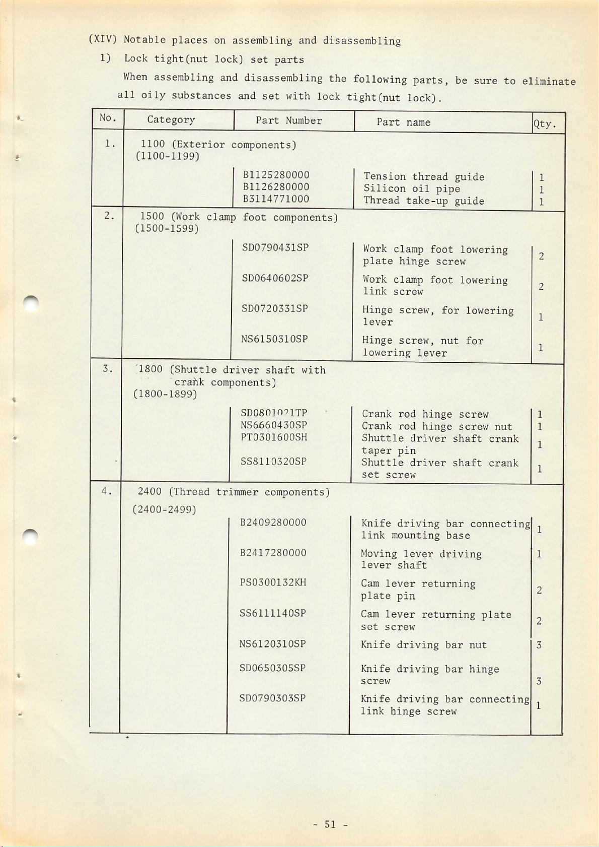
(XIV)
1}
Notable
Lock
tight(nut
places
on assembling and disassembling
lock)
set
parts
No.
3.
When
all
1.
2.
assembling
oily
1100
(1100-1199)
1500 (Work clamp
(1500-1599)
'1800
(1800-1899)
substances and
Category
(Exterior
(Shuttle
crahk
components)
and
disassembling the following
set
Part
with lock
Number
tight(nut
components)
B1125280000
B1126280000
B3114771000
foot
components)
SD0790431SP
SD0640602SP
SD0720331SP
NS6150310SP
driver
shaft
with
parts,
lock).
Part
name
Tension
Silicon
Thread
Work
plate
Work clamp
link
Hinge
lever
Hinge
lowering
thread
oil
take-up
clamp
hinge
screw
screw,
screw,
foot
foot
lever
be sure to eliminate
guide
pipe
guide
lowering
screw
lowering
for
lowering
nut
for
Qty.
1
1
1
2
2
1
1
SDOamo^lTP
NS6660430SP
PT0301600SH
•
4.
2400
(Thread
SS8110320SP
trimmer
components)
Crank
Crank
Shuttle
taper
Shuttle
set
screw
rod
rod
pin
hinge
hinge
driver
driver
screw
screw
shaft
shaft
nut
crank
crank
1
1
1
1
(2400-2499)
B2409280000
B2417280000
PS0300132KH
SS6111140SP
NS6120310SP
SD0650305SP
SD0790303SP
Knife
link
Moving
lever
Cam
lever
plate
Cam
lever
set
screw
Knife
Knife
screw
Knife
link
driving
mounting
lever
shaft
returning
pin
returning
driving
driving
driving
hinge
bar
base
driving
bar
bar
bar
screw
connecting
plate
nut
hinge
connecting
1
1
2
2
3
3
1
-
51
-
Page 55

5.
2500 (Feed
components)
(2500-2599)
6.
2600
(Stop-motion
components)
(2600-2699)
3000
(Pedal
unit
(3000-3099)
2) Grease applying
When
assemblingordisassembling
B2618280000
NS6150440SP
NS6150310SP
pressure
components)
B3023280000
SD0640324TP
places
SS6110620TP
mechanism
B2602280000
decreasing
the
following
Work
lever
clamp foot
set
Stop-motion
shaft
Stop-motion
shaft
Pressure
nut(large)
Pressure
nut(small)
Pin,
for
stopper
Stop-motion
plate
hinge
parts,
screw
lever
lever
spring
spring
lever
screw
be
sure
lifting
installing
installing
adjusting
adjusting
driving
to
apply
grease
(lithium
No.
1.
2.
group,
Category
1200 (Main
consistency
shaft,
components)
speed
(1200-1299)
B12**280010
2500 (Feed components)
No.2).
Part
Refer
number
decreasing
to
page
Part
Speed
ing
for
name
decreaS"
assembly
applying
Frictional
except
2cc
from
every
grease.
Remarks
to
main
2
cork
be
years
surface
surface
applied
shaft
(2500-2599)
B2534280000
3.
•
2600
(2600-2699)
(Stop-motion
components)
machanism
B26162800A0
B2618280000
Ball
connection
Stop-motion
regulating
lever
Stop-motion
regulating
lever
joint
shaft
Apply
on
left
carrier
Tip
of
condition
Outer
lever
from
felt
rim
shaft
side
bar
of
the
of
the
hole
feed
-
52
-
Page 56
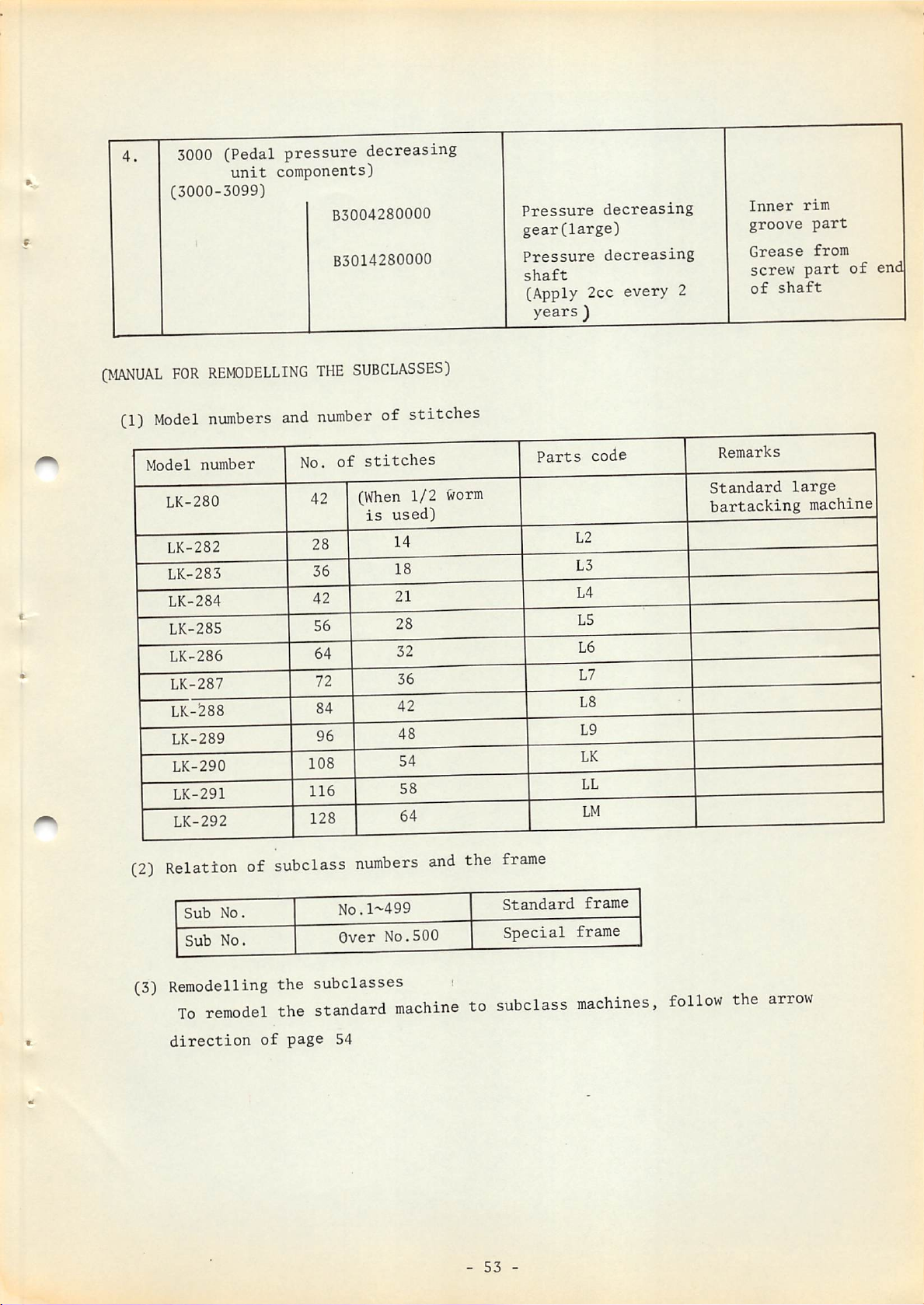
4.
3000
(3000-3099)
(Pedal
unit
pressure
components)
B3004280000
B3014280000
decreasing
Pressure
gear(large)
Pressure
shaft
decreasing
decreasing
(Apply 2cc every 2
years
)
Inner
groove
Grease
screw
of
shaft
rim
part
from
part
of
enc
(MANUAL
(1)
FOR
Model
Model
LK-280
LK-282
LK-283
LK-284
LK-285
LK-286
LK-287
LK-288
LK-289
LK-290
LK-291
LK-292
REMODELLING
numbers
number
and
THE
number
No.
SUBCLASSES)
of stitches
of
stitches
(When
1/2
Worm
is
used)
Parts
code
Remarks
Standard
bartacking
large
machine
(2)
Relation
Sub
Sub
(3) Remodelling
To
direction
of
No.
No.
remodel
of
subclass
the
subclasses
the
standard
page
54
numbers
N0.1M99
Over
No.500
and
the
frame
Standard
Special
i
machinetosubclass
-
53
-
frame
frame
machines,
follow
the
arrow
Page 57

REMODELLING
Exchanging
Feed
cam
Feed
plate
Work
clamp
Work
clamp
WI'lHIN
Part
foot(right)
foot(left)
SAME
STITCH
Blank
part
available
••
" '•
NUMBER
Remarks
Refertousage
of
blank
REMODELLINGBYCOMBINING
NUMBER, USED
Exchanging
Feed
Feed
Work
Work
Stop-motion
cam
Tension
tripping
"
cam
plate
clamp
clamp
Part
foot(TighC)
foot(left)
release
segment
regulating
link
1/2
WORM
Blank
part
available
"
Even
within
same
stitch
No.
tliere
are2kinds
of
worms
used:
partial
non-partial
worm
Number
changes
presence
partial
non-partial
worm
Remarks
or
with
of
or
Refertousage
of
blank
"
Refertostopmotion
regulating
cam
Ex.96--
stitches
48--
96
46
1--2ea.
2--1ea.
Feed
Feed
Work
Work
Stop-motion
cam
Tension
Feed
Feed
wheel
SAME
Exchanging
STITCH
cam
plate
clamp
clamp
cam
cam
Part
foot(right)
foot(left)
release
driving
driving
regulating
link
worm
worm
CHANGEOFNUMBER
Remarks
Blank
parts
available
" -
•1
Exclusive
available
depending
number
stitches
Exclusive
segment
available
depending
number
stitches
Exchange
depending
on
stitches
number"
"
cam
on
of
on
of
it
of
OF STITCHES
Refertousage
of
blank
"
Refertostop-
motion
regulating
cam
Refer
to
to
cam
wheel
"
tension
tripping
feed
worm
driving
release
segment
Refer
driving
feed
worm
and
cam
IREMODELLINGOFSUBCLASSESI
IN
Part
Needle
Shuttle
Needle
Needle
guide
CASE
name
hole
race
bar
bar
IN CASE SEWING
Condition:
from
standard
Remodelling
and
aft
sewing
sizetoover
6mm
Remodelling
and
aft
sewing
sizetoover
70inm
Remodelling
the
bigger
Remodelling
the
direction
the
direction
to
size
SIZEISCOMBINED
machine
fore
of
fore
of
make
-5+
Part
name
Work
clamp
mounting
for
large
Feed
plate
spring
Feed
across
connecting
rod(set)
Feed
across
driving
Feed
plate
spring
Work
clamp
foot
hook(right)
Work
clamp
foot
hook(left)
base
arm
size
foot
Part
No.
1)2S36L9SB00
D2S461.9SBOO
D2524L7VVOO
D2530L7W00
DS2545L4BB00
D2542L9SBOO
D2543284K00
CHANGINGOFSIZEOFNEEDLEISCOMBINED
Part
guide
thread
ring
No.
D2426282COO
B2426280000
B242628000B
E1817280000
B181728000B
B1401L7VV0O
B1405L7VVOO
Size
DP-17
Over
#11
#14,
#11
Over
of
needle
#18
#19
#18
#19
Over
#19
Remarks
Standard
Standard
Extreme
weight
Canton
of
over
sheets
heavy
material
material
10
thick
Page 58

(4)
Relation
No.
of
between
stitches
the
stop-motion
Part
No.
stop-motion
regulating
of
cam
cam and number
(When
1/2
is
used)
worm
of
stitches
Part
motion
cam
No.
of
regulating
stop-
(5)
For
For
For
For
stitches
For
stitches
For
stitches
For
Relation
tension
No.
(1/2
28
stitches
36
stitches
42
stitches
56,64
72,84
96,108,116
128
stitches
release
of
stitches
worm
used)
between
D2612282A00
B2612280000
D2612L7VV00
feed
link
tripping
Part
cam
No.
driving
segment
of
worm
worm,
with
For
For
For
For
For
For
For
feed
Part
wheel
14
stitches
18
stitches
21
stitches
28,32
36,42
48,54,58
64
stitches
cam
the
number
No.
stitches
stitches
driving
of
worm
stitches
of
stitches
worm
D2612284D00
D2612L5RU00
wheel
Part
tensioi;
link
and
No.
tripping
segment
of
release
28
36
42
56
64
72
84
96
108
116'
128
(14)
D2205282AOO
D2204282AOO
D2304282A00
(18)
(21)
(28)
B2205280000 B2204280000
D2205L5RUOO
D2204L5RU00
B2304280000
(32)
(36)
(42)
D2205L7VV00
D2204L7VV00
'
(48)
'
(54)
(58)
(64)
-
55
-
Page 59

(6)
i)
How
Part
In
to
numbers
case
use
the
the
blank
of
blank
stitching
feed
plate
work clamp
size
is
and
foot
within
blank
work^clamp
and blank feed
the
range
foot
plate
of
(vertical)60mm(2-3/18")
x
(crosswise)90mm(3-35/64"),
D-2551-L9SBV0
Large
clamp
right
Usage:
blank
foot
with
knurling
For
heavy
large'
work
tool
stitching
Large
clamp
knurling
weight
D-2552-L9SBV0
blank
foot
materials
-.size
use
tool
work
with
with
the
following
Large
left
clamp
right
Usage:For
blanks:
D-2551-L9SBW0
blank
foot
work
without
knurling
light
stitching
attached
clamp
foot
tool
weight
size
to
the
to
D-2552-L9SBW0
Large
clamp
left
material
to
be
backside
prevent
blank
foot
work
without
knurling
with
used
whencGnis
of
work
skip-stitching
tool
large
Large
joined,
Usage:
Large
work clamp
with
knurling
For
heavy
large
blank
stitching
feed
D-2551-L9SBX0
foot,
right
tool
weight
materials
size
D-2519-L9SBY0
plate
by
and
left
with
using
right
D-2551-L9SBY0
Large
joined,
Usage:
1.
work clamp
without
For
light
large
and
left
When
the
blanks
used,
parts
it
is
in
combination
D2S36L9SBA0...Work
D2560L9SBOO...Work
foot,
knurling
weight
stitching
joined
CAUTIONS
necessary
base
slide
on
D2S61L9SB00. . .Work-jclamp
slide
SS-1110640-TP.
2.
"Select
foot
mounting
center
at
nearly
clamp
the
of
foot.
the
the
" "
position
base
sewing
center
right
tool
materials
size
together.
ON
USAGE
this
to
:
clamp
for
clamp
plate
plate
of
set
screw
shape
of
and
by
using
page
use
foot
large
foot(right)
foot
Set
the
work clamp
can
the
blank
left
with
are
the
mounting
size
(left)
screw
so
that
be
right
to
be
following
(2)
the
placed
work
-
56
-
Page 60

In
case
the
stitching size is
within
the
50inmCl-31/32"), use the following blanks :
range(vertical)18inmC45/64")x(crosswise)
B-2551-280-0V0
Blank
foot
knurling
Usage
work
clamp
with
right
tool
: For heavy weight
small
stitching
B-2551-280-0X0
Blank work clamp
tool
and
left
and
foot
right
B-2552-280-0V0
Blank
with
tool
work
left
materials
size
with
right
foot
joined
clamp
knurling
with
knurling
together
foot
B-2551-280-0W0
Blank
foot
knurling
Usage
work
without
tool
: For
used
backside
clamp
right
light
wheniis
prevent
B-2551-280-0Y0
Blank work clamp
tool
and
left
together
B-2552-280-0W0
Blank
foot
knurling
weight
attached
of
work
skip-stitching
foot
without
and
right
work
without
tool
materials
clamp
foot
foot
knurling
joined
clamp
to
left
to be
the
to
Usage: For heavy weight
Blank
right
feed
and
left
B-2519-280-0Y0
plate
materials
foot
joined
with
together
Usage:
CAUTIONS ON OPERATION
1.
2.
For
light
Use
attached
clamp
and
the
to
foot
left
foot
standard
(B-2536-280-0A0)
blanks
Select
foot
the
are
the
mounting
center
to
position
of
weight materials with
the
and
be
base
the
used
joined
feed
when
used.
set
sewing
backside
mounting
all
of
the
screw so
of
with
right
together
of
the
work clamp
shape
work
base
that
can
above
placed at nearly the center of the blank
work
3.
When
right
one
the
off
clamp
.foot
installing
other
and
using
don't
foot.
the
blank
joined
part
installing
use
with
together,
only and cut
part
or
this
part.
left
use
and
either
off
shave
cDa
be
it
-
57
-
Page 61

ii)
Howtoprocess
By
referring
the
work clamp
to Table
1,
set
foot
the
work clamp
foot
mounting base to
the
either
screw
direction
Standard
mounting
Oscillating
foot
holes
of
mounting
of
A,B,C
the
sewing
work clamp
base
work
clamp
base
of
the
size.
foot
work clamp
TABLE
Fore
of
sewing
O-lBram
0-24mm
24-42nim
42-60mm
S)
@ ©C
and
foot
plate,
1
aft
direction
size
(23/32")
(61/64")
(61/64"-l-21/32")
(l-21/32"-2-3/8")
according
Set
foot
Fig.60)
to
the
position
mounting
B
A
B
C
fore
of
base(refer
and
work
aft
clamp
to
@
Attach
Process
@
surface
©
Drive
surface
@
To
it
surface.
@
Also,
is
clamp
preventing
all
the needle
of
the
the
machine
of
the
process the
liran
larger
as
shown
made
on
the
foot,
skip-stitching.
respective blanks.
by
shortening
work clamp
foot
in this condition
work
shape
than
in Fig.61,
lower
it
will
clamp
this
be
foot.
of the needle
needle
if
surface
very
effective
Fig.60
it
so
and
set
and
drop
drop
mark
a protrusion
of
the
work
in
that
it
it.
make
needle
part of the
and
makeafacing
will barely contact the
drop
marks
work
clamp
If, Work
r?
on
foot, process
of
30*^onthe
/
•0.4
Feed
the
clamp
T
plate
upper
upper
upper
foot
-
58
-
Fig.61
Page 62

iii)
@
Processing
As
there
the
sewing
the
feed
plate
are2kindsofshapesofthe
specifications
and
Cloth
process
A
shape
feed
it.
plate,
Work
foot
selectitin
clamp
Cloth
accordance
B
shape
Work
with
clamp
foot
Shape
Note
Cloth
Special
of
feed
thickness
features
plate
Feed
The
of
the
larger
clamp
Heavy
\
7
plate
needle
feed
by
foot.
weight
1^
drop
plate
0.2mm
0.2
hole
should
than
material
mm
shape
the
be
work
A
f
Feed
plate
The groove shape
plate
than
the
The
clamp
small
Trimmed
No
should
the
work
outer
foot
as
Light
thread
bobbing
be
outer
clamp
shape
should
possible.
weight
of
.
mm
of
1mm
shape
foot.
of
be as
material
is
cloth.
feed
larger
of
the
short.
work
-
59
-
Page 63

AO-10
(1) Cautions on assembling and disassembling
1)
UNIT
When
(ONE
the
PEDAL
machine
FOR
head
LK-280)
is to
be
installed
on
the table for
AO-10
unit,
do
not
use nut and washer of the
the bed base, as the lever
surface of the table, acts as a
the
top
of
the
table.
2)
When
lifting
it
installing the
stud to the hole at the
with
the
stop
ring.(Fig.61)
work
furthest
instaUing
substitute
clamp,foot
end
adjusting
rear
screw of the 3 screws
base
which
for the nut. So,
lifting
of the
Safety
chain, insert the
work
clamp
Work
clamp
Stop
plate-
Work clamp
is
attached to the
screw
foot
lifting
foot
lifting
ring
foot
lifting
for
work
lever
chain
installing
bottom
this
in
clamp
lever
and
from
foot
set
3)
When
hinge
installing
screws
and by screwing
The
hinge
lever,
so do
Starting
A , B to
screws
not
the
starting
starting
into
the
A
and
mix them
connecting
Fig.61
connecting
starting
lever's
connecting
bar,
hole
B are temporarily
up.(Fig,62)
bar
I
insert
and
bar
set
the connecting
pedal
lever's
and firmly
hole, respectively,
tighten
bar
the
to the respective holes of the
set
nut.
Fig.62
-
60
-
Page 64

4) Be
left
sure
and
to
right
carefully
and
up
adjust
and
down
the
position
clearance
of
of
0.3mm(l/64")
the
safety
O.Sinin
of
adjusting
plateCFig.61).
direction
broken,
5)
Adjusting
Adjust
the
spring
grease
so
the
to
becomes
be
careful.
the
spring
spring
retainer
the
rim
If
the
larger,
switching
roller
area
clearance
the
switching
cam
base
of
the
•Spring
Spring
of
safety
cam
either
will
roller
switching
m
retainer
0.3nun
adjusting
up
move
base.
of
the
plate
and
down
smoothly.
(Fig.63)
cam
roller
horizontal
may
or
left
Also,
base
be
and
apply
right
sufficient
so
that
6) The
is
to
roller
be
7) As shown
stud
AO-10
the
direction.
part
is
LK-280 model and
used,
in
of
to
Work
base
so
Fig.64,
the
be
purchased,
clamp
set
hinge
be
very
work clamp
stop-motion
adjust
lifting
screw
careful
regulating
install
so
}
Fig.63
nut(NS-6110530-SP)
when
lifting
assembling
returning
lever
the
work clamp
that
the
starting
Starting
of
is
the
or
disassembling.
spring
AO-10.
lifting
lever
goes
lever
place
is
attached
So,
when
returning
up
toward
for
only
lock
to
spring
the
tight
the
the
to
arrow
Fig.64
8) AO-10
pedal
uses
plate
a
pedal
adjusting
plate
plate
for
lockstitching
by
sliding
-
61
but,
its
hole,
-
as
one
shown
by
in
one.
Fig.65,
Also,
set
the
the
pedal
Page 65

plate
So,
stopper
adjust
by
screw
the
is
pedal
attached
plate
to
support
the
pedal
arm
set
plate
screw
and
so
pedal
that
plate
at
stop-motion
support
arm,
Pedal
bushing
(2)
1) The
position
(l/64--S/64").(Fig.66)
D
Order
AO-8
goes
Pedal
L-@—>
of
order
unit
up
at
the
clearance
stopper
Fig.65 Fig.66
operation
of
operation
and
operates
the
same
Pe^l
Cn=)
Pedal
screw
adjusting
of
the
time
of
of
in
with
the
pedal
plate
machine
the
machine and
the
order
the
plate
as
stop-motion
stopper
1.S-2mm
shown
the
pedal
in
of
screw
Pedal
is
Fig.67.
the
machine.
comes
to
1.5--2iTim
(Stop-motion)
Pedal
stopper
same as
screw
the
The work clamp
previous
foot
m
(3)
Adjustments
1) At
lever's
to
the
stop-motion
long
hole
l.S--2mm(l/16--S/64")
(Fig.69)
to
adjust
part
to
time,
this
the
and
as
When
the
machine
Fig.67
clearance
the
starting
shown
clearance.
-
in
62
stops
between
lever
Fig.68.
This
-
First
(Work
nut
comes
the
hinge
Turn
locks
step
clamp
the
of
pedal
foot
down)
stop-motion
screw
chain
up
should
at
each
Second
(Machine
regulating
be
adjusting
half
m
step
of
pedal
starts)
matched
nut
turn.
Page 66

Stop-motion
0
regulating
1.5-2mm
II
lever
Starting
hinge
lever
screw
2)
When
the pedal
not
go
up,
turn
Also,
friction
be
3)
When
smooth.
the
when
of
work
the above causes,
cam
smoothly and
it
up
and
down.
4)
When
the machine
operation,
on
strongly,
up
without
the
starting
Fig.68
is
stepped
the
chain
the
work clamp
work clamp
clamp
if
if
not,
is
work
the
clamp
machine
the
on
adjusting
foot
one step
foot
lifting
lifting
up
nut(Fig.69)
lever
foot does not go up
the spring switching
then
started
will
machine,
foot
adjust
and
will
start.
if
the pedal
stop
pull
the
When
the
Chain
Fig.69
and
down
lever's
and
to
right.
movement
components so
at
the
stop-motion time,
roller
spring
is
moving
switching cam(Fig.63) by
is
returned in the midst of pedal
going up. But
the
work clamp
safety
plate
adjusting
the
work
is
that
bad,
the
nut-"'^
clamp
lessen
movement
verify,
the spring switching
if
the
pedal
foot
is
to
be
strongly
toward
foot does
the
will
besides
moving
is
stepped
raised
the
arrow
direction.(Fig.70)
Safety
adjusting
plate
I
Fig.70
-
63
Safety
-
plate
Page 67

ENGINEERS
MANUAL
OF
AO-11
set
digest
Pedal
AO-11
sideways
(1)
Cautions
As a
the
connecting
To
connecting
bar
connecting
stud
is
a
unit
the
INSTRUCTION
basic
pedal
install
composed
on
the
table
on
assembling
step,
connecting
lever
bar
the
and
pedal
stud
of
and
BOOK
install
bar
the
connecting
retainer
components.(Fig.72)
bar
retainer
models
to
on AO-10
and
disassembling
the
in
place
pedal
so
LK-284-10, LK-282-20,
which
AO-10
AO-10
thoroughly,
unit
of
pedal
connecting
bar
stud
that
there
(Note)
This
unit
sideways
lever
bar
set
will
is a
Pedal
is
installed.
on
stud,
stud
retainer.(Fig.71)
screw,
be no
view
from
connecting
244mm
LK-284-40
the
table
install
install
friction
etc.
Please
and
by
the
pedal
the
pedal
of
pedal
the
backsideofthe
Pedal
connecting
lever
which
read
and
exchanging
connecting
/
are
table
bar
9
Pedal
Fig.71
connecting
Fig.72
bar
529mm
stud
retainer
-
64
-
Page 68
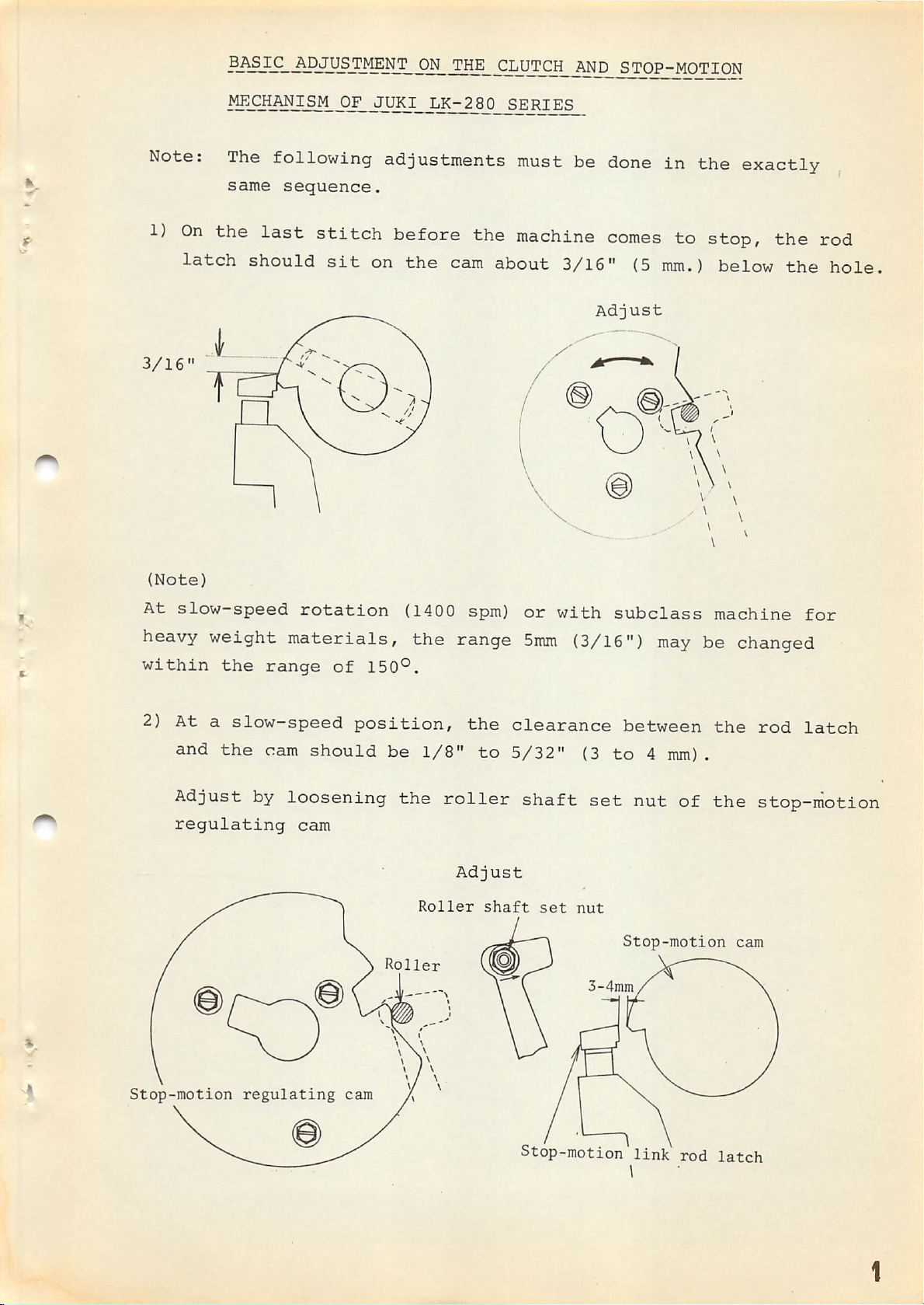
BASK;_j^pjUSTMENTONTHE
CLUTCH
jUSJD
STOP-MOTION
Note:
1)
3/16"
(Note)
On
latch
The
same
the
following adjustments must be
sequence.
last
should
stitch
sit
before the
on
the
cam
machine
about
3/16"
Adjust
done
comes
(5
in
the
exactly
to stop, the rod
mm.)
below
the
hole
At
slow-speed
heavy weight
within
2)
At
and
the
a
slow-speed
the
Adjust by
regulating
rotation
materials,
range
cam
of
should
loosening
cam
(1400
the
150®.
position,
be
the
Roller
Roller
1/8"
roller
spm)
range
the
to
Adjust
shaft
or
with
5mm
clearance
5/32"
(3/16")
shaft
set
nut
(3
set
3-4mm
subclass
to
may
between
4 mm).
nut
of
Stop-motion
machine
be changed
the
rod
the
stop-motion
cam
for
latch
Stop-motion
regulating
cam
Stop-motion
link
rod
latch
Page 69
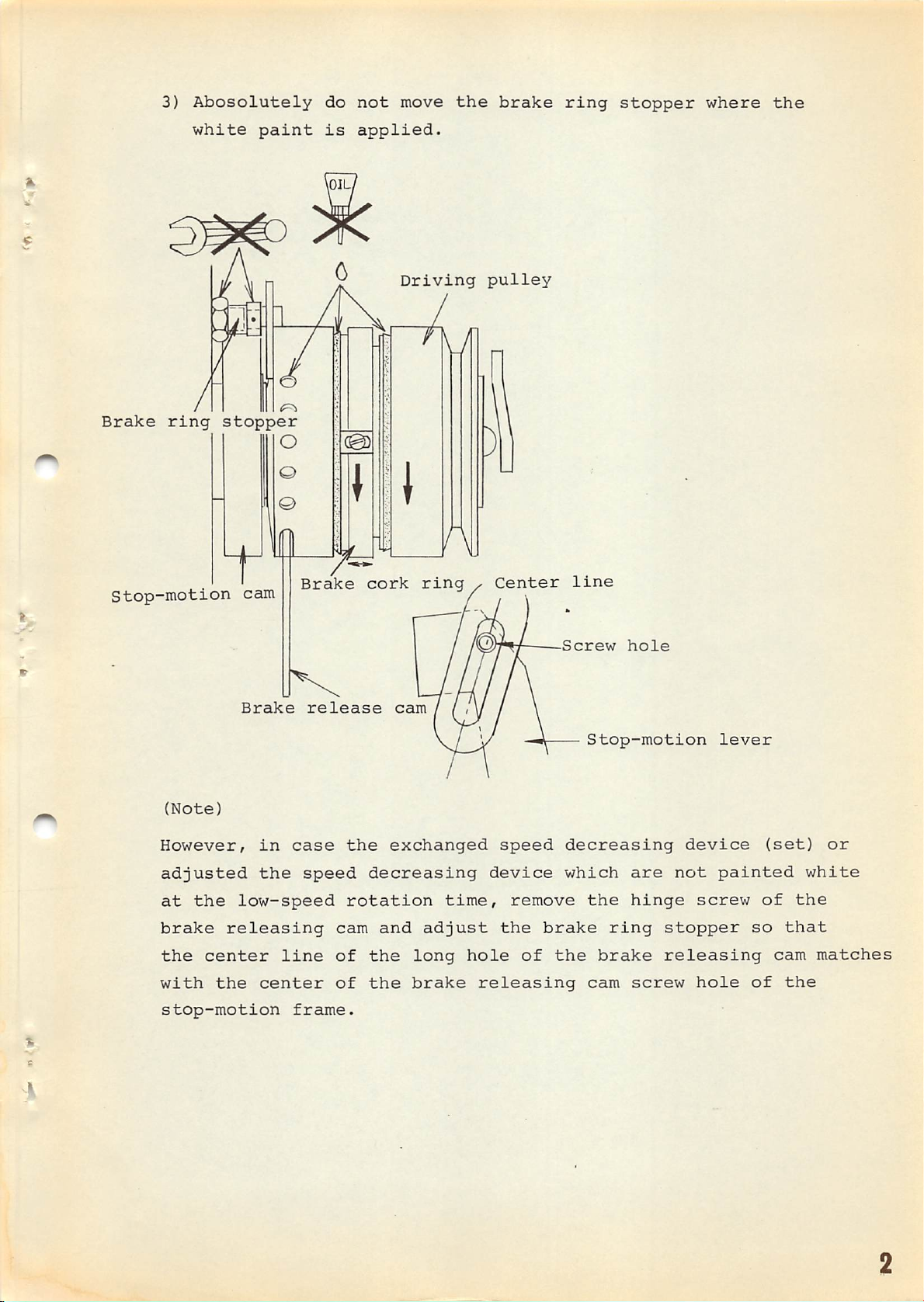
3)
Abosolutely
do
not
move
the
brake
ring
stopper
where
the
Brake
ring
white
paint
stopper
is
applied.
Driving
O
O
©
HI
pulley
Stop-motion
(Note)
However/
adjusted
at
the
brake
the
with
stop-motion
low-speed
releasing
center
the
cam
Brake
in
the
center
Brake
case
speed
line
frame.
release
cork
the
decreasing
rotation
cam
of
the
of
the
ring
cam
exchanged
and
adjust
long
brake
time,
hole
/
Center
speed
device
remove
the
releasing
brake
of
line
Screw
Stop-motion
decreasing
which
the
ring
the
brake
cam
hole
are
hinge
screw
lever
device
not
painted
screw
stopper
releasing
hole
so
of
(set)
of
cam
or
white
the
that
matches
the
Page 70

4)
The
clutch should
the
rod
latch
comes
be
engaged
off
the
for the
cam.
slow
The
brake cork
speed
just
ring
after
(the
middle
slow
Stop-motion
ring)
speed.
is
link
rod
Stop-motion
During
'pulley
stationary
latch
cam
this
is
running
Adjustment should be done as
whenever
interval,
follows:
idly.
^
When
the
machine
the
stop-motion
is
at
its
link
rod
latch
stop-motion
adjust
each
so
other.
5) Before
it
runs
driving
half
rotation
is
placed
cam, move
that
the
the
machine goes from
idly
pulley).
(the
(180
on
the
brake
brake
The
to
the
ring
proper
200
outer
brake
cork
degrees).
circumference
cork
and
the
ring
ring
the
cork
slow speed
rotates
length
of
fore
part
counter
idling
part
and
barely
to
the
is
of
the
aft
and
touch
high speed,
to
the
about
one
Page 71
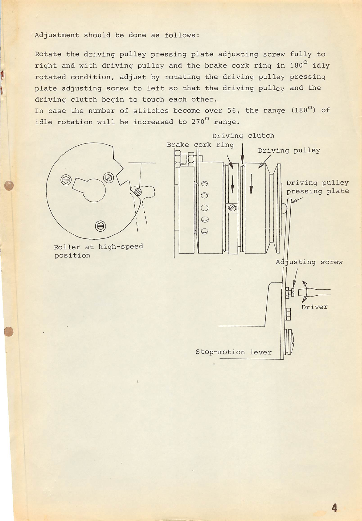
Adjustment
should
be
done
as
follows:
Rotate
right
rotated
plate
driving
In
case
idle
the
and with
condition,
adjusting
clutch
the
rotation
driving
number
will
pulley
driving
adjust
screw
begin
of
be
pressing
pulley
by
to
left
to
touch
stitches
increased
and
rotating
so
that
each
become
to
Brake
plate
the
brake cork
the
the
other.
over
270°
cork
adjusting
driving
driving
56,
range.
Driving
ring
1
ring
the
clutch
I
screw
pulley
pulley
range
Driving
\
in
Driving
pressing
fully
180°
pressing
and
the
(180°)
pulley
to
i^ly
of
pulley
plate
Roller
position
at
high-speed
Stop-motion
lever
Adjusting
screw
Driver
Page 72

•''If
n-.
.•k'l
- •
'.
.A-
'
A'
»♦■
 Loading...