

JUKI LH-4100 Instruction Manual

ENGLISH

CONTENTS
1. SPECIFICATIONS ........................................................................................................... 1
2. NAME OF EACH COMPONENT .................................................................................... 2
3. INSTALLATION ............................................................................................................... 3
3-1. Installing the bottom cover .................................................................................................................................. 3
3-2. Opening and closing of the control box (SC-910) .............................................................................................4
3-3. Adjusting the height of the knee lifter ................................................................................................................4
3-4. Installation of thread stand .................................................................................................................................. 5
3-5. Caution when installing the panel ...................................................................................................................... 5
3-6. Connecting the cord ............................................................................................................................................. 6
3-7. Managing the cord ................................................................................................................................................ 8
3-8. Adjusting the knee lifter detection seat (asm.) ................................................................................................ 10
4. PREPARATION OF THE SEWING MACHINE ............................................................. 11
4-1. Lubrication .......................................................................................................................................................... 11
4-2.Cleaningthelter ...............................................................................................................................................
4-3. Adjusting the amount of oil in the hook .......................................................................................................... 13
4-4. Attaching the needles ........................................................................................................................................13
4-5. How to take out the bobbin case ...................................................................................................................... 14
4-6. Inserting a bobbin in a bobbin case .................................................................................................................14
4-7. Threading the machine head ............................................................................................................................. 15
4-8. Thread tension .................................................................................................................................................... 16
4-9. Thread take-up spring ........................................................................................................................................ 16
4-10. Adjusting the stitch length ..............................................................................................................................17
4-11. Winding the bobbin thread ..............................................................................................................................18
4-12. Adjusting the needle stop position ................................................................................................................. 19
4-13. Pedal pressure and pedal stroke .................................................................................................................... 20
4-14. Adjustment of the pedal ................................................................................................................................... 20
12
5. OPARATION OF THE SEWING MACHINE .................................................................. 21
5-1. Pedal operation ................................................................................................................................................... 21
5-2. Hand lifter ............................................................................................................................................................ 22
5-3. Adjusting the pressure of the presser foot ...................................................................................................... 22
5-4. Thread tension release changeover when using the knee lifter ....................................................................23
5-5. Separately driven needle changeover switch (for LH-4168-7 and 4188-7) .................................................... 24
5-6. One-touch reverse feed switch lever (for touch-back) ................................................................................... 25
6. MAINTENANCE ............................................................................................................ 25
6-1. Changing procedure to bottom feed and the adjustment (LH-4128 without thread trimmer only)............. 25
6-2. Changing procedure to needle feed (for LH-4128 only) ................................................................................. 27
6-3. Adjusting the inner hook guide ......................................................................................................................... 28
6-4. Needle-to-hook relation ..................................................................................................................................... 29
6-5. Adjusting the height and the inclination of the feed dog ...............................................................................32
6-6. Adjusting the presser foot ................................................................................................................................. 32
6-7. Move (adjustment) of the hook shaft saddle when replacing the gauge ......................................................33
6-8. Lubricating route when changing the needle gauge size ............................................................................... 33
6-9. Adjusting the thread presser spring ................................................................................................................. 33
6-10. Adjusting the position of the moving knife .................................................................................................... 34
6-11. Replacing the bobbin thread slack preventer spring (for LH-4168-7 and 4188-7) ......................................35
6-12. Adjusting the hook needle guard .................................................................................................................... 35
6-13. Stop of the needle bars and angle of corners for corners stitching (for LH-4168-7 and 4188-7) ...............36
6-14. Caution when installing the gauge to the bed slide ...................................................................................... 36
6-15. Position of the wiper ........................................................................................................................................37
6-16.Replenishinggreasetothespeciedplaces(forLH-4168-7and4188-7) ...................................................
37
7. STITCH-TO-ANGLE TABLE BY GAUGE(PITCH AND mm CONVERSION TABLE) .. 39
8. GAUGE SETS ............................................................................................................... 40
9. TROUBLES AND CORRECTIVE MEASURES ............................................................ 45
iv

1. SPECIFICATIONS
Model name
Application
Hook
Thread trimmer
Separately
driven needle
bar mechanism
Max. sewing
speed
Needle
Gauge size
Lift of presser
foot
Lubrication
Noise
LH-4128
For light- and
medium-weight
materials
S type : standard, F type : foundation, G type : jeans
Small hook
Not provided
Not provided
4,000 rpm *
DP x 5 #9 to #16 (For S type), DP x 5 #9 to #11 (For F type), DP x 5 #16 to #22 (G type)
1/8" to 1-1/2"
3.2 to 38.1 mm
12 mm by knee lifter, 5.5 mm by hand lifter lever, 9 mm by knee lifter with wiper
Workplace-related
noise at sewing
speed
n = 4,000 min–1 :
Lpa
according to DIN
84 dB(A)
≦
Noise
measurement
45635-48-A-1.
LH-4128-7
(with automatic
thread trimmer)
For light-, medium-
and heavy-weight
materials
Small hook
Provided
Not provided
4,000 rpm *
5/32" to 1-1/4"
4 to 31.8 mm
New Defrix Oil No. 1
Workplace-related
noise at sewing
speed
n = 4,000 min–1 :
Lpa
according to DIN
84 dB(A)
≦
Noise
measurement
45635-48-A-1.
LH-4168-7
(with automatic thread
trimmer incorporating
corner stitching)
For light-, medium-
and heavy-weight
materials
Small hook
Provided
Provided
3,200 rpm
5/32" to 1"
4 to 25.4 mm
Workplace-related
noise at sewing
speed
n = 3,200 min–1 :
Lpa
according to DIN
84 dB(A)
≦
Noise
measurement
45635-48-A-1.
LH-4188-7
(with automatic thread
trimmer incorporating
corner stitching)
For medium- and
heavy-weight
materials
Large hook
Provided
Provided
3,200 rpm
5/32" to 1"
4 to 25.4 mm
Workplace-related
noise at sewing
speed
n = 2,700 min–1 :
Lpa
according to DIN
84 dB(A)
≦
Noise
measurement
45635-48-A-1.
* 3,500 rpm when the stitch length exceeds 4 mm.
– 1 –
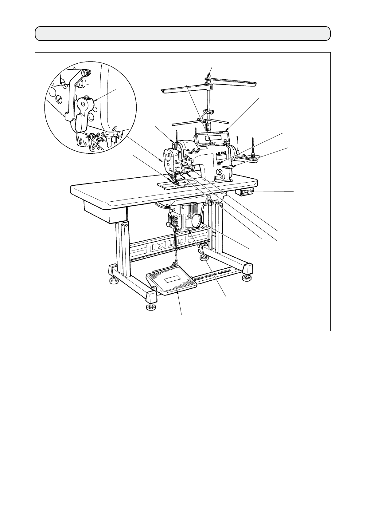
2. NAME OF EACH COMPONENT
!2
!5
3
2
!1
7
!0
9
!3
!4
8
4
1
Separately driven needle
1
changeover switch
Thread take-up cover
2
Finger guard
3
Thread tension controller
4
Control box
5
Pedal
6
Knee lifter lever
7
Power switch
8
Hand switch
9
Operation panel
!0
6
5
Bobbin winder
!1
Thread stand
!2
Oil supply opening
!3
Reverse feed control lever
!4
Hand lifter lever
!5
– 2 –
3. INSTALLATION
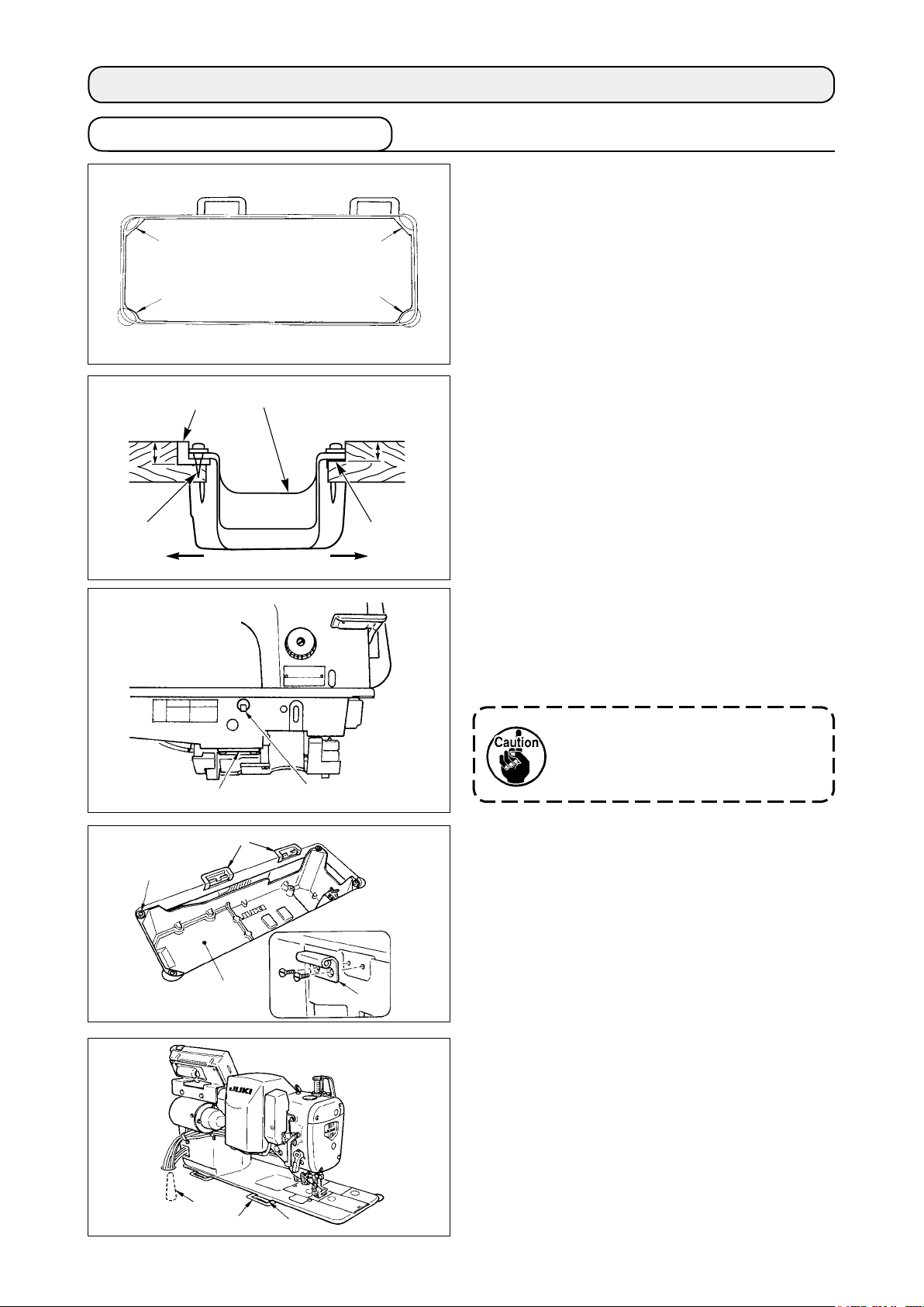
3-1. Installing the bottom cover
1) The bottom cover should rest on the four
corners of the machine table groove.
23.5 mm
2
3
1
1
A
4
B
3
1
19.5 mm
3
2) Fix two head support rubber seats
1
front side A to the protruding section of the
machine table using nails 2. Fix two machine
head cushion seats 3 on hinge side B using
a rubber-based adhesive, Then place bottom
cover 4 on the xed seats.
3) Remove air vent cap
attached to the
5
machine bed. (Be sure to attach cap 5 when
transporting the machine head in the state
that the machine head is removed from the
machine table.)
on the
8
C
4
7
5
6
If the sewing machine is operated
without removing air vent cap 5,
oil leakage from gear box portion
may occur.
C
4) Fit hinge
to the machine main body with
6
screws.
Fit the machine head to table rubber hinges
and place it on head cushions 8 on the
7
four corners.
5) In case the AK-device is not provided, attach
head support rod
to the machine table.
9
9
7
6
– 3 –
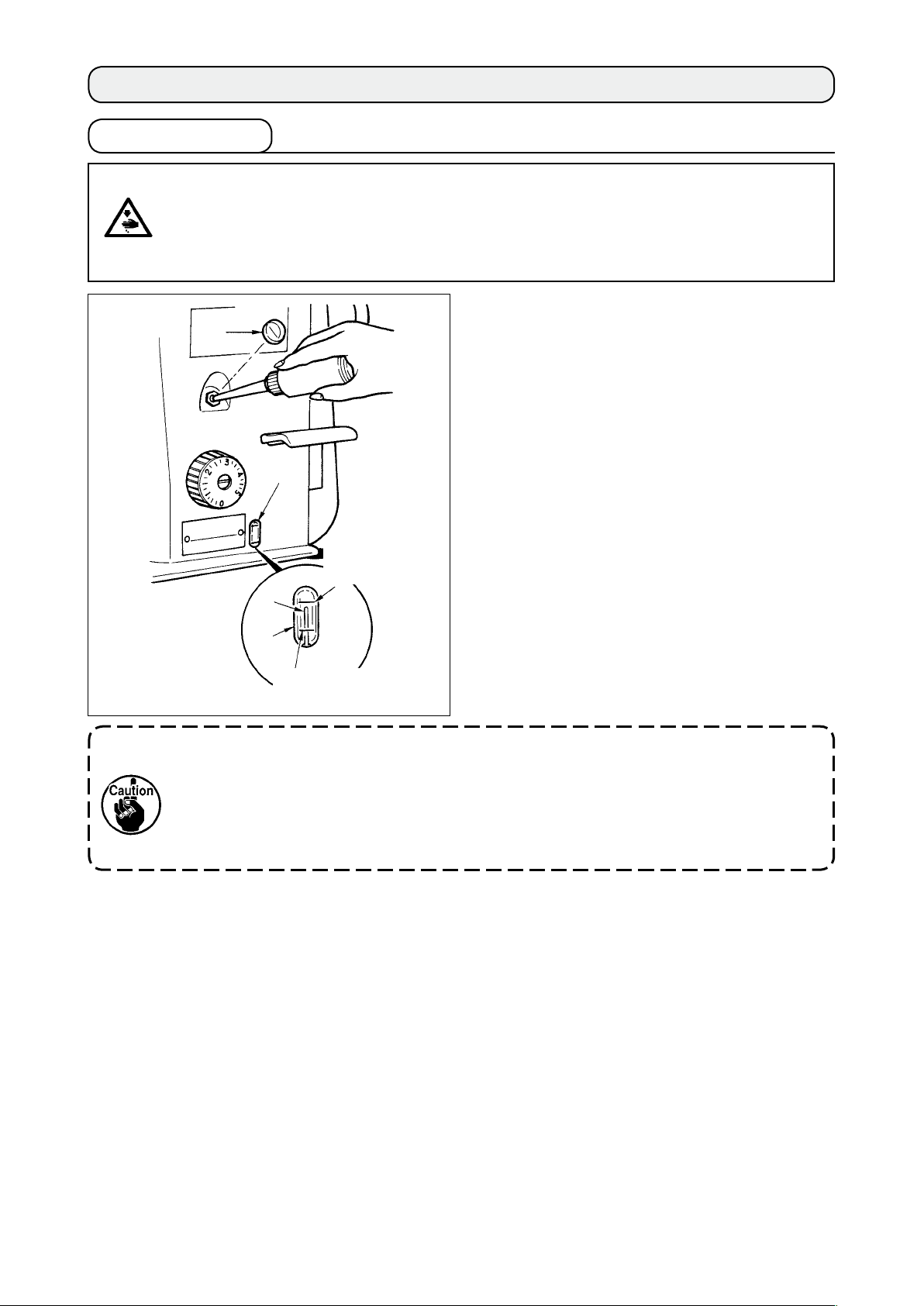
3-2. Opening and closing of the control box (SC-910)
2
1
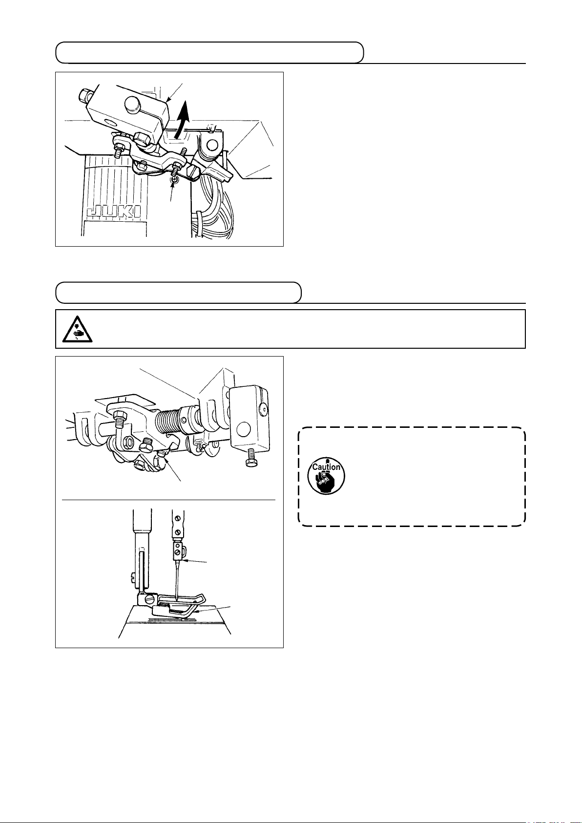
3-3. Adjusting the height of the knee lifter
WARNING :
Turn OFF the power before starting the work so as to prevent accidents caused by abrupt start of
the sewing machine.
When opening and closing the control box, move
th e knee lifter co mp onents 2 to the po sition
where screw hole 1 can be observed and perform
the work.
For the connection of the cords and setting of the
control box, refer to the Instruction Manual for
SC-910 together with this Instruction Manual.
1
2
3
1) The standard height of the presser foot lifted
using the knee lifter is 12 mm.
2) You can adjust the presser foot lift up to 13
mm using knee lifter adjust screw
1
.
D o no t o p e r a te t h e s ew i n g
mach i ne i n th e stat e th at the
presser foot 3 is lifted by 12 mm
or more since the needle bar 2
comes in contact with the presser
foot 3.
– 4 –
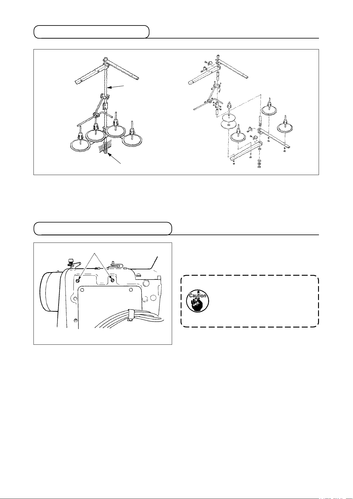
3-4. Installation of thread stand
2
1
Assemble the thread stand, set it up on the machine table using the installation hole in the table and
tighten nut
When you use power supplied by the overhead power line, pass the power supply cord through hollow
spool rest rod
gently.
1
2
.
3-5. Caution when installing the panel
1
Use washers, toothed lock washers, and screws
mounted on the machine head when installing
1
the panel.
The screws attached to the panel
may d amag e th e screw hole s
since the pitch of the screws is
different from that of the machine
head.
– 5 –
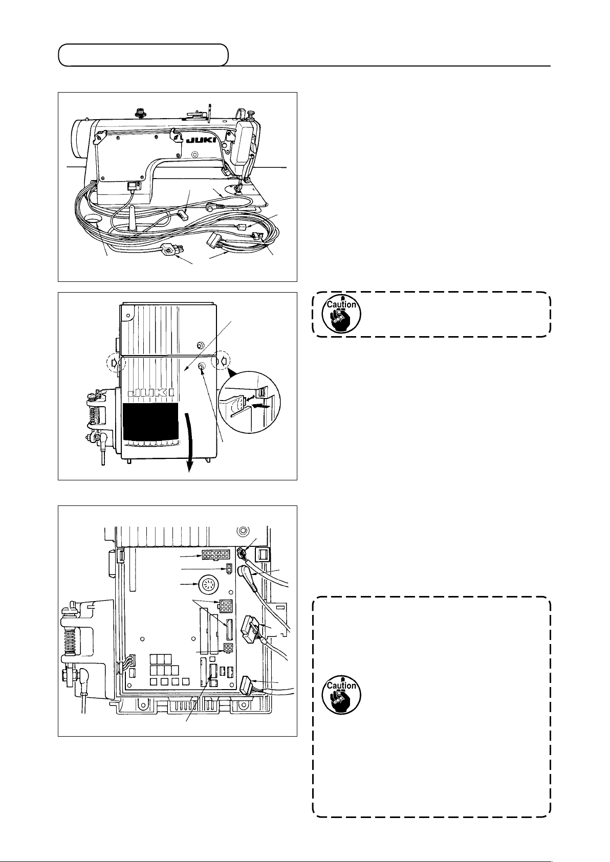
3-6. Connecting the cord
(1) LH-4128,4128-7,4168-7,4188-7
2
5
4
1) Pass the cords
of the thread trimming
笊
solenoid, reverse-stitching solenoid, etc.,
and the cords of the synchronizer 笆, safety
switch 笳, machine head 4P connector 笘,
motor signal 笙, motor output 笞through hole
A in the table to route them down under the
machine table.
2) Loosen setscrew
A
6
1
3
3) Pressing the side of front cover
direction of the arrow, open the front cover
in front cover
!2
!5
in the
!5
.
toward you.
Be sure to open / close the front
!5
4) Connect 14P code
machine head to connector
cover with your hands.
coming from the
1
(CN46).
7
5) Connect 4P connector coming from the
machine head
6) Connect 4P connector
to connector 笨 (CN31).
笘
(safty switch
笳
connector) coming from the machine head to
!2
connector
(CN48).
笶
7) Connect 7P connector
machine head to connector
8) Connect connector
笙
machine head to connector
coming from the
笆
(CN30).
筐
coming from the
(CN38, CN39).
筺
(Connect 8P connector to CN38 and in case
7
!0
@0
!1
!9
2
3
of 9Pconnector, connect to CN39.)
9) When the optional AK125 device is attached,
connect 2P connector
device to connector
coming from the AK
筴
(CN40).
筧
Be su re to secur ely inser t t he
r e s p e c t i v e connectors af ter
8
1
9
4
5
checking the inserting directions
sin ce all con nec tor s h ave the
inserting directions. (When using a
type with lock, insert the connectors
until they go to the lock.)
The sewing machine is not actuated
$5
unless the connectors are inserted
properly. In addition, not only the
problem of error warning or the
like occurs, but also the sewing
machine and the control box are
damaged.
– 6 –

(2) 4168-7,4188-7
Optional unit A
@3
@6
#2
@5
#0
#1
@4
@2
@1
In addition to “3-6. (1)”, connect the cords below.
1) Pass separately driven needle changeover switch cord
and separately driven needle sensor cord @3 through hole A in the table to route them down
@2
, separately driven needle solenoid cord
@1
under the machine table.
2) Connect 10P connector
Connect 8P connector @2 coming from the machine head to connector @5 (CN129).
3)
Connect 6P connector @3 coming from the machine head to connector @6 (CN128).
4)
Remove the cord extending from #2 (COM) from #0 (BNC) and connect it to #1 (LH).
5)
@1
ing from the machine head to connector @4 (CN125).
com
$4
$2
$3
$0
Remove setscrew $0 located on the left-hand
6)
side of the power switch, and place the point
of earth cord (asm.)
lifter detecting sensor plate (asm.)
coming from knee
$3
$2
setscrew. Then tighten the setscrew.
When the earth cord has not been
connected, malfunction will be
caused.
7) Connect knee lifter detection sensor
connector
– 7 –
to connector $5 (CN32).
$4
to the
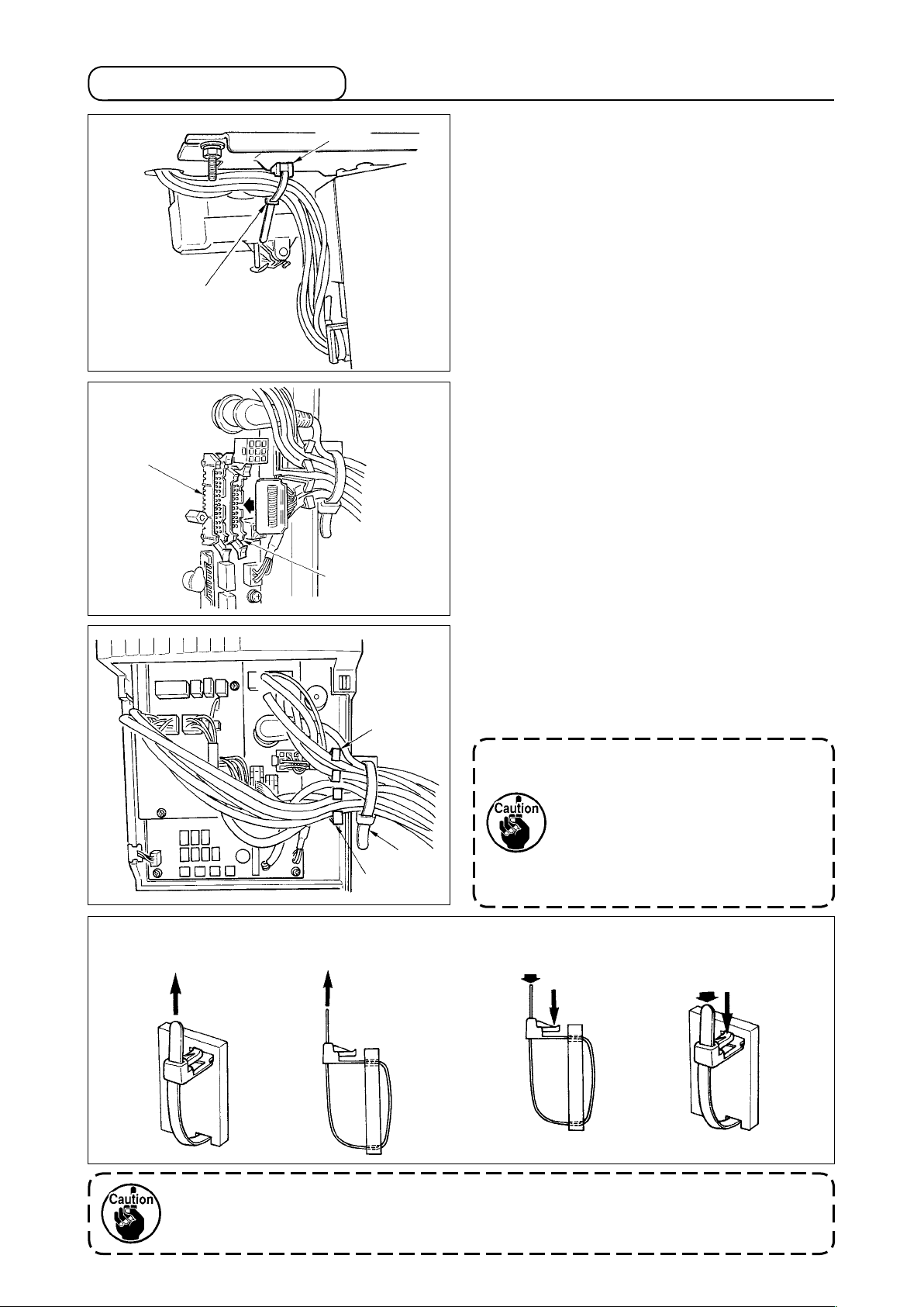
3-7. Managing the cord
B
@3
A
!4
@5
1) Fix all cables coming from the machine head
with cable clip band
.
綏
attached to tie-mount
絽
[Connection of the connector for CP panel]
Exclusive connectors are prepared for connection
of the connector for CP-160.
Paying attenti o n t o the o r i e n t ation of th e
connector, connect it to connector
located on
笋
the circuit board. After connecting, securely lock
the connector.
[Connecting for IP panel]
The connector for connecting IP-100 and IP-110
are prepared.
When connecting, insert the connector until it is
locked to
筬
.
2) After inserting the connector, put all cords
together with cable clip band
located on
!3
the side of the box. At this time, bundle the
cords (connector CN46) of thread trimming
solenoid, reverse feed solenoid, etc., AK
cord (connector CN40) and motor signal cord
(connector CN39) to wire saddle
, bundle
@5
detector cord (connector CN30) above wire
saddle
(connector CN32) between wire saddles
and
, knee lifter detection sensor cord
@5
and other cords to wire saddle
@6
@6
@5
.
1. Fix the cord clamp and the
cable clip band following the
attaching procedure.
2. When removing the connector,
!3
@6
remove it from the wire saddle
and remove it while pressing
the hook of the cable clip band.
Howtoxcableclipband
Pull
筍
Pull
How to remove cable clip band
Push
Push
Pushing the hook portion, push the band to remove it.
Push the hook.
1. Fixthecableclipbandfollowingtheattachingprocedureasshowninthegure.
2. To remove the cable clip band, push the cable clip band until it comes off while pressing
thehookofthebandfollowingtheremovingprocedureasshowninthegure.
– 8 –
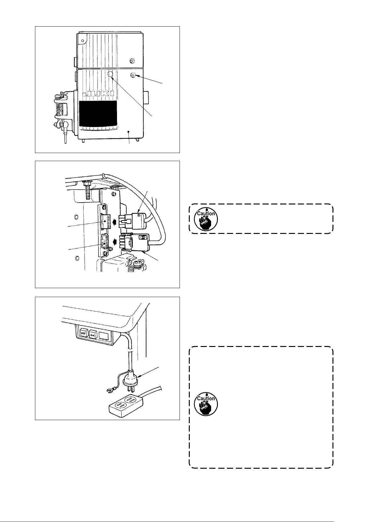
筌
絽
笄
3) Close front cover
while paying attention to
筌
pinching of the wire.
Lightly press portion 絽 and insert front cover
with “click”.
筌
4) After that, x it with the screw
笄
.
筅
筥
笞
筵
5) Connect motor output cord
to connector
笞
located on the side of the box.
6) Connect connector 4P
to connector
筥
.
of the power switch
筵
Route the motor output cord from
the front face of the box.
7) Make sure that the power switch is turned
OFF and insert power supply cord
coming
筰
from the power switch into the power plug
socket. (Illustration is for the japanese
specication 100V type.)
筅
筰
1. Top end of power supply cord
varies in accordance with
destination or supply voltage.
Check again the supply voltage
and the voltage designated on
the control box when installing
the switch.
2. Prepare the power switch
conformed to the safety
standard.
3. Be sure to connect the ground
wire (green / yellow).
– 9 –
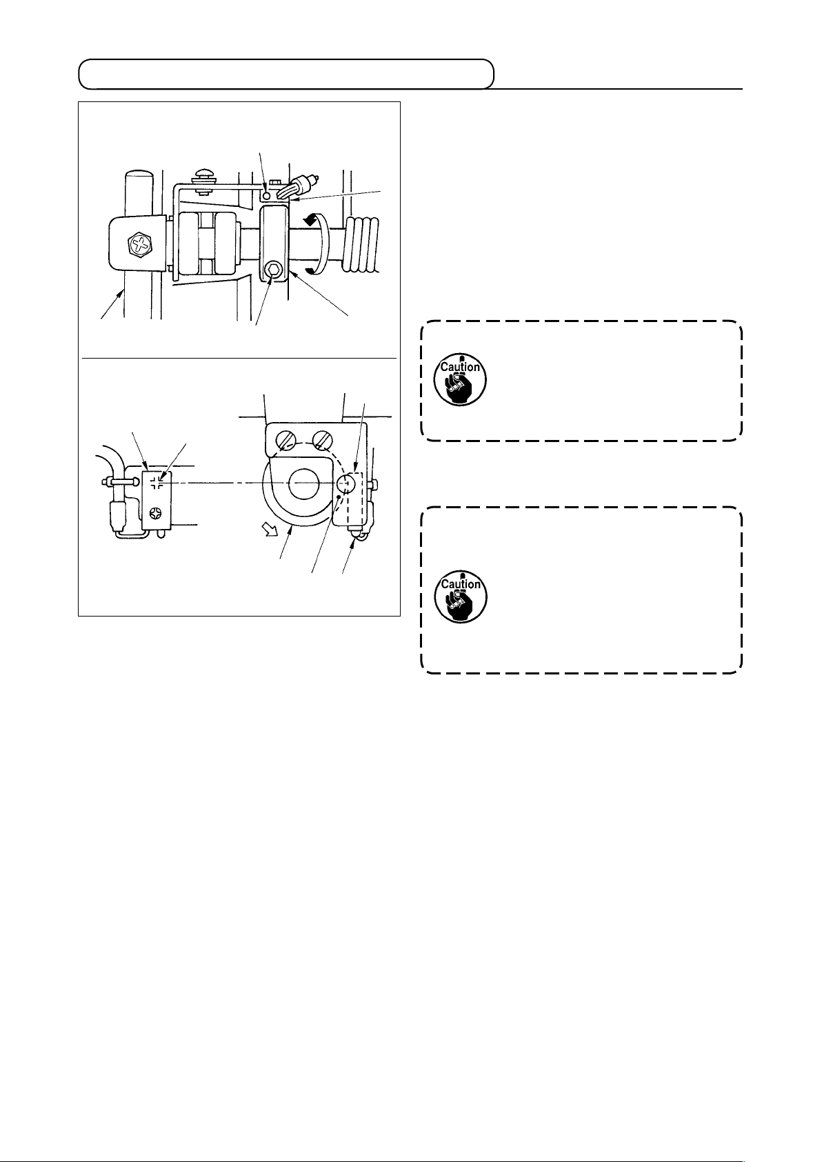
3-8. Adjusting the knee lifter detection seat (asm.)
1) Turn ON the power.
Conditions : LED starts lighting at presser
foot lift of 5 mm.
7
3
Detection section
LED
!3
To align
edges
4
3
3
2) Press knee p
foot by 5 mm from the top surface of throat
plate.
3) Turn knee lifter detection seat (asm.)
direction of the arrow and x it at the position
where LED of knee lifter detection sensor
starts lighting with setscrew
align the edge of detection seat (asm.)
with that of knee lifter detection sensor
Whe n t he edges of k nee li fter
4) Conrm that LED goes out when knee pad
plate
ad plate
and lift
7
the presser
4
. At this time,
!3
det ecti on s enso r 3 a nd k nee
lifter detection seat (asm.) 4 are
not aligned, detection trouble will
be caused.
is released.
7
in the
3
4
.
3
4
Magnet
* For explanation, the figure above omits knee pad
plate and the like.
LED
It is adjus ted s o that the kn ee
lifting motion is detected when
presser f oot is lifted by 5 mm.
When using it with the lift amount
of less tha n 5 mm, r edu ce the
standard adjustment value and
re-adjust according to step 3).
5) When the magnet of knee lifter detection seat
(asm.)
comes near the detection section
4
(+ mark section) of knee lifter detection
sensor
, it detects that knee lifting has been
3
performed and LED lights up.
– 10 –
4. PREPARATION OF THE SEWING MACHINE
4-1. Lubrication
WARNING :
1. Do not connect the power plug until the lubrication has been completed so as to prevent
accidents due to abrupt start of the sewing machine,
2. Topreventtheoccurrenceofaninammationorrash,immediatelywashtherelatedportionsif
oil adheres to your eyes or other parts of your body.
3. If oil is mistakenly swallowed, diarrhea or vomitting may occur. Put oil in a place where children
cannot reach.
Fill the oil tank with oil for hook lubrication before
1
2
Upper engraved
marker line
3
2
Lower engraved
marker line
operating the sewing machine.
1) Remove oil hole cap 1 and fill the oil tank
with JUKI New Defrix Oil No. 1 using the oiler
supplied with the machine.
2) Fill the oil tank with the oil until the top end
of oil amount indicating rod 3 aligns with
the upper engraved marker line of oil amont
indicating window 2.
If the oil is lled excessively, it will leak from
the air vent hole in the oil tank or proper
lubrication will be not perform ed. So, be
careful.
3) When you operate the sewing machine, rell
oil if the top end of oil amount indicating rod
comes down to the lower engraved marker
3
line of oil amount indicating window
2
.
• When you use a new sewing machine or a sewing machine after an extended period
of disuse, use the sewing machine after performing break-in at 3,000 rpm or less.
• For the oil for hook lubrication, purchase JUKI New Defrix Oil No. 1 (Part No. :
MDFRX1600C0).
• Do not use again the oil gathered in the bottom cover since it will cause the trouble
of lubrication.
– 11 –
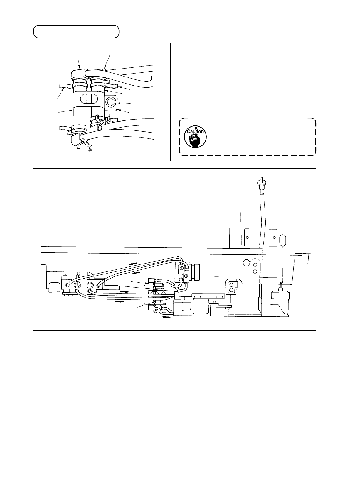
4-2.Cleaningthelter
8
9
!0
!0
9
8
7
6
Periodically clean filter sections
and 5 (2
4
places) (approximately once in three months).
1) Loosen setscrews
of oil tube holder 6
7
and remove and remove the lter from the
machine bed.
2) Loosen pipe stopper
and joint
!0
.
, and remove tube 9
8
3) After removing dust adhered to the net section
of joint
, return the lter to its home position.
!0
Whentheltersclogwithdustor
the like, trouble of lubrication
occurs and trouble of the sewing
machine will be caused.
Lubrication to hook
Circulation
4
5
Lubrication
– 12 –
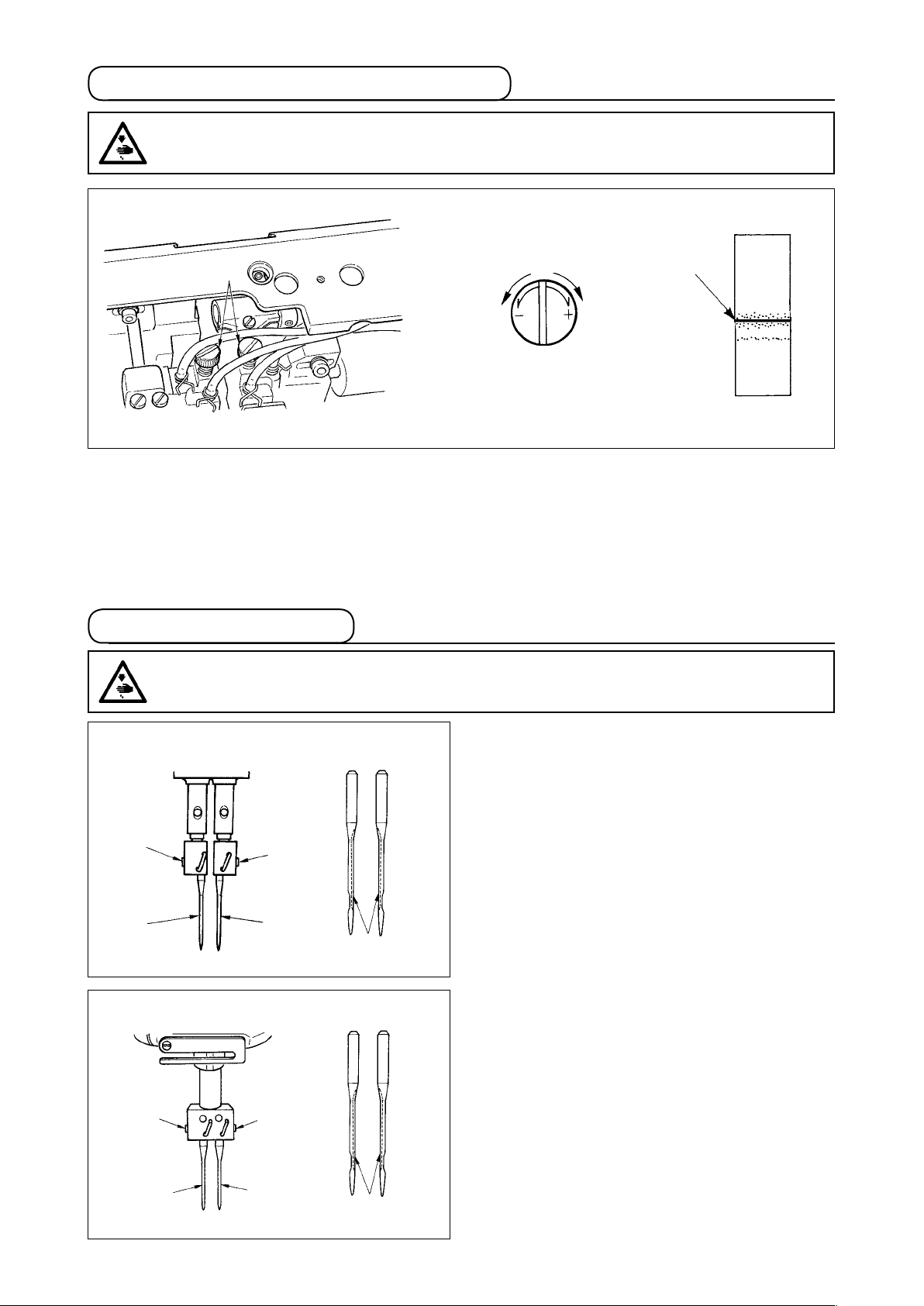
4-3. Adjusting the amount of oil in the hook
WARNING :
Turn OFF the power before starting the work so as to prevent accidents caused by abrupt start of
the sewing machine.
1
Oil amoun t
decreases
Oil splashes
Oil amount
increases
Adjust the amount oil using adjusting screw 1. Turn screw 1 clockwise to increase the amount of oil
in the hook or counterclockwise to decrease it. Measure the amount of oil in ve seconds. When the
amount of oil is excessively decreased, break-down will be caused. So, be careful.
4-4. Attaching the needles
WARNING :
Turn OFF the power before starting the work so as to prevent accidents caused by abrupt start of
the sewing machine.
LH-4168-7, 4188-7
2
1
LH-4128, 4128-7
2
2
1
2
3
Switch "off" the motor.
Use DPx5 needles.
1) Turn the handwheel until the needle bar has
come up to the highest point of its stroke.
2) Loosen needle clamp screws 2 and pick up
two needles 1 in the way that their grooves
are facing outwards.
3
3) Insert the needles into the needle clamp as
far as they will go.
4) Tighten needle clamp screws 2 rmly.
1
1
3
– 13 –
 Loading...