

JUKI DDL-9000C-S Series, DDL-9000C-F Series, DDL-9000C Series, DDL-9000C-SMS, DDL-9000C-FMS Engineer's Manual
...Page 1

Direct-drive, High-speed, Sewing system
with Automatic Thread Trimmer
DDL-9000C Series
(DDL-9000C-F, S Series)
ENGINEER’S MANUAL
40177390
No. E424-00
Page 2

PREFACE
This Engineer’s Manual is written for the technical personnel who are responsible for the service and mainte-
nance of the machine.
The Instruction Manual for these machines intended for the maintenance personnel and operators at an
apparel factory contains operating instruction in detail. And this manual describes “Standard Adjustment”,
“Adjustment Procedures”, “Results of Improper Adjustment”, and other important information which are not
covered in the Instruction Manual.
When carrying out the maintenance work on the sewing machine, be sure to refer also to the Instruction
Manual and the Parts List. Further, refer to Engineer’s Manual.
In addition, for the motor for the sewing machine with thread trimmer, refer to the separate Instruction Manual
or This manual gives the “Standard Adjustment” on the former page under which the most basic adjustment
value is described, and on the latter page “Results of Improper Adjustment” under which stitching errors and
troubles arising from mechanical failures and “How to adjust” are described.
Page 3

TO ENSURE SAFE USE OF YOUR SEWING MACHINE
Adjustment :
It means replacement of parts,
disassembly, and repair assembly.
For the sewing machine, automatic machine and ancillary devices (hereinafter collectively referred to as
"machine"), it is inevitable to conduct sewing work near moving parts of the machine. This means that there
is always a possibility of unintentionally coming in contact with the moving parts. Operators who actually
operate the machine and maintenance personnel who are involved in maintenance and repair of the machine
are strongly recommended to carefully read to fully understand the following
engineer's manual before using/maintaining the machine. The content of the
Safety precautions
Safety precautions
of this
of this
engineer's manual includes items which are not contained in the specications of your product.
The risk indications are classied into the following three different categories to help understand the meaning
of the labels of this engineer's manual and the product. Be sure to fully understand the following description
and strictly observe the instructions.
(I) Explanation of risk levels
DANGER :
This indication is given where there is an immediate danger of death or serous injury if the person in charge or any third
party mishandles the machine or does not avoid the dangerous situation when operating or maintaining the machine.
WARNING :
This indication is given where there is a potentiality for death or serious injury if the person in charge or any third party
mishandles the machine or does not avoid the dangerous situation when operating or maintaining the machine.
CAUTION :
This indication is given where there is a danger of medium to minor injury if the person in charge or any third par ty
mishandles the machine or does not avoid the dangerous situation when operating or maintaining the machine.
Items requiring special attention
(II)
Explanation of pictorial warning indications and warning labels
Be aware that holding the sewing
machine during operation can
hurt your hands.
There is a risk of entanglement
in the belt resulting in injury.
There is a risk of injury if you
touch the button carrier.
The correct direction is indicated.
Connection of a earth cable is
indicated.
Pictorial warning indication
There is a risk of injury if contacting a moving section.
There is a risk of electrical shock if
contacting a high-voltage section.
There is a risk of a burn if contacting a high-temperature section.
Be aware that eye deciency can
be caused by looking directly at
the laser beam.
There is a risk of contact between
your head and the sewing machine.
indication
Pictorial warning
Indication label
❶
❸
❷
❶
❷
• There is the possibility that slight to serious injury or death may be caused.
❶
• There is the possibility that injury may be caused by touching moving part.
• To perform sewing work with safety guard.
❷
Warning label
• To perform sewing work with safety cover.
• To perform sewing work with safety protection device.
• Be sure to turn the power OFF before carrying out "machine-head threading,"
❸
"needle changing," "bobbin changing" or "oiling and cleaning.
danger label
Electrical-shock
i
❸
Page 4

SAFETY PRECAUTIONS
Accident means "to cause
personal injury or death or
damage to property."
DANGER
1.
When it is necessary to open the control box containing electrical parts, be sure to turn the power off and
wait for ve minutes or more before opening the cover in order to prevent accident leading to electrical
shock.
CAUTION
Basic precaution
1. Be sure to read the engineer's manual and other explanatory documents supplied with accessories of
the machine before using the machine. Carefully keep the engineer's manual and the explanatory documents at hand for quick reference.
2. The content of this section includes items which are not contained in the specications of your product.
3. Be sure to wear safety goggles to protect against accident caused by needle breakage.
4. Those who use a heart pacer have to use the machine after consultation with a medical specialist.
5. Turn OFF the power before starting the work in order to protect against accident that can result in personal injury.
If it is inevitable to carry out work with the power ON, utmost care should be taken to prevent from de-
pressing the foot pedal or pressing the start switch by mistake.
6. Make sure, after the completion of replacement work, that neither connectors nor cables are damaged,
slipped off or loosened in order to protect against accident that can result in personal injury.
Safety devices and warning labels
1. Be sure to operate the machine after verifying that safety device(s) is correctly installed in place and
works normally in order to prevent accident caused by lack of the device(s).
2. If any of the safety devices is removed, be sure to replace it and verify that it works normally in order to
prevent accident that can result in personal injury or death.
3. Be sure to keep the warning labels adhered on the machine clearly visible in order to prevent accident
that can result in personal injury or death. If any of the labels has stained or come unstuck, be sure to
change it with a new one.
Application and modication
1.
Never use the machine for any application other than its intended one and in any manner other than that
prescribed in the engineer's manual in order to prevent accident that can result in personal injury or death.
JUKI assumes no responsibility for damages or personal injury or death resulting from the use of the
machine for any application other than the intended one.
2.
Never modify and alter the machine in order to prevent accident that can result in personal injury or death.
JUKI assumes no responsibility for damages or personal injury or death resulting from the machine
which has been modied or altered.
Education and training
1. In order to prevent accident resulting from unfamiliarity with the machine, the machine has to be used
only by the operator who has been trained/educated by the employer with respect to the machine operation and how to operate the machine with safety to acquire adequate knowledge and operation skill. To
ensure the above, the employer has to establish an education/training plan for the operators and educate/train them beforehand.
Items for which the power to the machine has to be turned off
Turning the power off: Turning the power switch off, then removing the power plug from the outlet. This
applies to the following.
1. Be sure to immediately turn the power off if any abnormality or failure is found or in the case of power
failure in order to protect against accident that can result in personal injury or death.
2. To protect against accident resulting from abrupt start of the machine, be sure to carry out the following operations after turning the power off. For the machine incorporating a clutch motor, in particular,
be sure to carry out the following operations after turning the power off and verifying that the machine
stops completely.
2-1. For example, threading the parts such as the needle, looper, spreader etc. which have to be thread-
ed, or changing the bobbin.
2-2. For example, changing or adjusting all component parts of the machine.
2-3. For example, when inspecting, repairing or cleaning the machine or leaving the machine.
3. Be sure to remove the power plug by holding the plug section instead of the cord section in order to pre-
vent electrical-shock, earth-leakage or re accident.
4. Be sure to turn the power off whenever the machine is left unattended between works.
5. Be sure to turn the power off in the case of power failure in order to prevent accident resulting of break-
age of electrical components.
PRECAUTIONS TO BE TAKEN IN VARIOUS OPERATION STAGES
ii
Page 5

Transportation
1. Be sure to lift and move the machine in a safe manner taking the machine weight in consideration. Refer
to the text of the engineer's manual for the mass of the machine.
2. Be sure to take sufcient safety measures to prevent falling or dropping before lifting or moving the
machine in order to protect against accident that can result in personal injury or death.
3. Once the machine has been unpacked, never re-pack it for transportation to protect the machine against
breakage resulting from unexpected accident or dropping.
Unpacking
1. Be sure to unpack the machine in the prescribed order in order to prevent accident that can result in
personal injury or death. In the case the machine is crated, in particular, be sure to carefully check nails.
The nails have to be removed.
2. Be sure to check the machine for the position of its center of gravity and take it out from the package
carefully in order to prevent accident that can result in personal injury or death.
Installation
(I) Table and table stand
1.
Be sure to use JUKI genuine table and table stand in order to prevent accident that can result in personal
injury or death. If it is inevitable to use a table and table stand which are not JUKI genuine ones, select the
table and table stand which are able to support the machine weight and reaction force during operation.
2. If casters are tted to the table stand, be sure to use the casters with a locking mechanism and lock
them to secure the machine during the operation, maintenance, inspection and repair in order to prevent
accident that can result in personal injury or death.
(II) Cable and wiring
1.
Be sure to prevent an extra force from being applied to the cable during the use in order to prevent electri-
cal-shock, earth-leakage or re accident. In addition, if it is necessary to cable near the operating section
such as the V-belt, be sure to provide a space of 30 mm or more between the operating section and the cable.
2. Be sure to avoid starburst connection in order to prevent electrical-shock, earth-leakage or re accident.
3. Be sure to securely connect the connectors in order to prevent electrical-shock, earth-leakage or re
accident. In addition, be sure to remove the connector while holding its connector section.
(III) Grounding
1. Be sure to have an electrical expert install an appropriate power plug in order to prevent accident caused
by earth-leakage or dielectric strength voltage fault. In addition, be sure to connect the power plug to the
grounded outlet without exceptions.
2. Be sure to ground the earth cable in order to prevent accident caused by earth leakage.
(IV) Motor
1. Be sure to use the specied rated motor (JUKI genuine product) in order to prevent accident caused by
burnout.
2. If a commercially available clutch motor is used with the machine, be sure to select one with an entan-
glement preventive pulley cover in order to protect against being entangled by the V-belt.
Before operation
1. Be sure to make sure that the connectors and cables are free from damage, dropout and looseness be-
fore turning the power on in order to prevent accident resulting in personal injury or death.
2. Never put your hand into the moving sections of the machine in order to prevent accident that can result
in personal injury or death.
In addition, check to be sure that the direction of rotation of the pulley agrees with the arrow shown on
pulley.
3. If the table stand with casters is used, be sure to secure the table stand by locking the casters or with
adjusters, if provided, in order to protect against accident caused by abrupt start of the machine.
During operation
1. Be sure not to put your ngers, hair or clothing close to the moving sections such as the handwheel,
hand pulley and motor or place something near those sections while the machine is in operation in order
to prevent accident caused by entanglement that can result in personal injury or death.
2. Be sure not to place your ngers near the surround area of the needle or inside the thread take-up lever
cover when turning the power on or while the machine is in operation in order to prevent accident that
can result in personal injury or death.
3. The machine runs at a high speed. Never bring your hands near the moving sections such as looper,
spreader, needle bar, hook and cloth trimming knife during operation in order to protect your hands
against injury. In addition, be sure to turn the power off and check to be sure that the machine completely stops before changing the thread.
4. Be careful not to allow your ngers or any other parts of your body to be caught between the machine
and table when removing the machine from or replacing it on the table in order to prevent accident that
can result in personal injury or death.
5.
Be sure to turn the power off and check to be sure that the machine and motor completely stop before removing the belt cover and V-belt in order to prevent accident caused by abrupt start of the machine or motor.
6.
If a servomotor is used with the machine, the motor does not produce noise while the machine is at rest.
Be sure not to forget to turn the power off in order to prevent accident caused by abrupt start of the motor.
7. Never use the machine with the cooling opening of the motor power box shielded in order to prevent re
accident by overheat.
iii
Page 6

Lubrication
1. Be sure to use JUKI genuine oil and JUKI genuine grease to the parts to be lubricated.
2. If the oil adheres on your eye or body, be sure to immediately wash it off in order to prevent inamma-
tion or irritation.
3. If the oil is swallowed unintentionally, be sure to immediately consult a medical doctor in order to pre-
vent diarrhea or vomiting.
Maintenance
1. In prevention of accident caused by unfamiliarity with the machine, repair and adjustment has to be car-
ried out by a service technician who is thoroughly familiar with the machine within the scope dened in
the engineer's manual. Be sure to use JUKI genuine parts when replacing any of the machine parts. JUKI
assumes no responsibility for any accident caused by improper repair or adjustment or the use of any
part other than JUKI genuine one.
2. In prevention of accident caused by unfamiliarity with the machine or electrical-shock accident, be sure
to ask an electrical technician of your company or JUKI or distributor in your area for repair and maintenance (including wiring) of electrical components.
3. When carrying out repair or maintenance of the machine which uses air-driven parts such as an air cyl-
inder, be sure to remove the air supply pipe to expel air remaining in the machine beforehand, in order to
prevent accident caused by abrupt start of the air-driven parts.
4. Be sure to check that screws and nuts are free from looseness after completion of repair, adjustment
and part replacement.
5. Be sure to periodically clean up the machine during its duration of use. Be sure to turn the power off
and verify that the machine and motor stop completely before cleaning the machine in order to prevent
accident caused by abrupt start of the machine or motor.
6. Be sure to turn the power off and verify that the machine and motor stop completely before carrying out
maintenance, inspection or repair of the machine. (For the machine with a clutch motor, the motor will
keep running for a while by inertia even after turning the power off. So, be careful.)
7. If the machine cannot be normally operated after repair or adjustment, immediately stop operation and
contact JUKI or the distributor in your area for repair in order to prevent accident that can result in personal injury or death.
8. If the fuse has blown, be sure to turn the power off and eliminate the cause of blowing of the fuse and
replace the blown fuse with a new one in order to prevent accident that can result in personal injury or
death.
9. Be sure to periodically clean up the air vent of the fan and inspect the area around the wiring in order to
prevent re accident of the motor.
10. In order to prevent accidents resulting in personal injury or death, adjustments have to be carried out
within the instructions described in this Engineer's Manual and in the Instruction Manual by the personnel who have been well trained by the employer with respect to the latest knowledge and safety for the
machine.
11. Make sure that water is contained in cylinders and pipes, then remove water from them in order to pre-
vent accidents due to a malfunction of the machine.
Operating environment
1. Be sure to use the machine under the environment which is not affected by strong noise source (electro-
magnetic waves) such as a high-frequency welder in order to prevent accident caused by malfunction of
the machine.
2. Never operate the machine in any place where the voltage uctuates by more than "rated voltage ±10 %"
in order to prevent accident caused by malfunction of the machine.
3. Be sure to verify that the air-driven device such as an air cylinder operates at the specied air pressure
before using it in order to prevent accident caused by malfunction of the machine.
4. To use the machine with safety, be sure to use it under the environment which satises the following
conditions:
Ambient temperature during operation 5°C to 35°C
Relative humidity during operation 35 % to 85 %
5. Dew condensation can occur if bringing the machine suddenly from a cold environment to a warm one.
So, be sure to turn the power on after having waited for a sufcient period of time until there is no sign
of water droplet in order to prevent accident caused by breakage or malfunction of the electrical components.
6. Be sure to stop operation when lightning ashes for the sake of safety and remove the power plug in
order to prevent accident caused by breakage or malfunction of the electrical components.
7. Depending on the radio wave signal condition, the machine may generate noise in the TV or radio. If this
occurs, use the TV or radio with kept well away from the machine.
8. In order to ensure the work environment, local laws and regulations in the country where the sewing
machine is installed shall be followed.
In the case the noise control is necessary, an ear protector or other protective gear should be worn according to the applicable laws and regulations.
9. Disposal of products and packages and treatment of used lubricating oil should be carried out properly
according to the relevant laws of the country in which the sewing machine is used.
iv
Page 7

PRECAUTIONS TO BE TAKEN IN VARIOUS OPERATION STAGES
MECHANICAL COMPONENTS
CAUTION
Transportation
1. Be sure to lift this machine with four or more workers and use a carriage for moving it in order to prevent personal injury.
2. Be sure to take sufcient safety measures to prevent falling or dropping before lifting or moving the
machine in order to protect against accident that can result in personal injury or death.
3. Installation is described in the Instruction Manual. Be sure to fully understand the description before
putting the machine into operation.
Replacement of parts
1. In prevention of accident that can result in personal injury, be sure to carry out disassembly/assembly
work within the specied range given in this Engineer's Manual and in the Instruction Manual.
2. Turn OFF the power before starting the work in order to protect against accident that can result in personal injury.
If it is inevitable to carry out work with the power ON, utmost care should be taken to prevent from de-
pressing the foot pedal or pressing the start switch by mistake.
3. Be sure to carry out replacement work after having installed the machine in a stable state in order to
protect against accident that can result in personal injury.
In addition, be sure to select appropriate tools.
4. In prevention of accident that can result in personal injury, make sure, after the completion of adjustment work, that neither screws nor nuts are loosened or come in contact with other parts.
5. Be sure to use JUKI genuine parts when replacing any of the machine parts.
JUKI assumes no responsibility for any accident caused by any part other than JUKI genuine one.
In addition, in the event you cannot replace parts within the specied range, immediately stop the replacement work and ask JUKI or distributor in your area for replacement of the parts.
Adjustment
1. Be sure to adjust according to the instructions given in this Engineer's Manual and in the Instruction
Manual in order to protect against accident that can result in personal injury.
2. Be sure to carry out replacement work after having installed the machine in a stable state in order to
protect against accident that can result in personal injury.
In addition, be sure to select appropriate tools.
3. In prevention of accident that can result in personal injury, make sure, after the completion of adjustment work, that neither screws nor nuts are loosened or come in contact with other parts.
4. Turn OFF the power before starting the work in order to protect against accident that can result in personal injury.
If it is inevitable to carry out work with the power ON, utmost care should be taken to prevent from de-
pressing the foot pedal or pressing the start switch by mistake.
5. In prevention of accident that can result in personal injury or entanglement accident, be sure to ensure
safety at the time of test run. In addition, be sure to take care not to allow hair or cloths to come in contact with the machine belt.
Disassembly/assembly
1. In prevention of accident that can result in personal injury, be sure to carry out disassembly/assembly
work within the specied range given in this Engineer's Manual and in the Instruction Manual.
2. Be sure to carry out replacement work after having installed the machine in a stable state in order to
protect against accident that can result in personal injury.
In addition, be sure to select appropriate tools.
3. In prevention of accident that can result in personal injury, make sure, after the completion of adjustment work, that neither screws nor nuts are loosened or come in contact with other parts.
4. In prevention of accident that can result in personal injury, be sure to tighten screws and nuts in assembly work with a specied torque, if specied, or with an appropriate torque, if not specied.
After the completion of assembly work, be sure to check that screws and nuts are not loosened before
starting test run.
5. In prevention of accident that can result in personal injury, be sure to check whether the direction of
rotation is correct at the time of test run.
6. In prevention of accident that can result in personal injury or entanglement accident, be sure to ensure
safety at the time of test run. In addition, be sure to take care not to allow hair or cloths to come in contact with the machine belt.
v
Page 8

PRECAUTIONS TO BE TAKEN IN VARIOUS OPERATION STAGES
ELECTRICAL COMPONENTS
CAUTION
Transportation
1. Be sure to lift this machine with four or more workers and use a carriage for moving it in order to prevent personal injury.
2. Be sure to take sufcient safety measures to prevent falling or dropping before lifting or moving the
machine in order to protect against accident that can result in personal injury or death.
3. Installation is described in the Instruction Manual. Be sure to fully understand the description before
putting the machine into operation.
Replacement of parts
1. In prevention of accident caused by unfamiliarity with the machine or electrical-shock accident, be sure
to ask an electrical technician of your company or JUKI or distributor in your area for replacement of
electrical components.
2. When it is necessary to open the control box containing electrical parts, be sure to turn the power off
and wait for ve minutes or more before opening the cover in order to prevent accident caused by unfamiliarity with the machine or electrical-shock accident. In addition, do not carry out replacement work
with wet hands in order to prevent electrical-shock accident.
3. Be sure to replace parts according to the instructions given in this Engineer's Manual and in the Instruction Manual in order to protect against accident that can result in personal injury.
4. Be sure to carry out replacement work after having installed the machine in a stable state in order to
protect against accident that can result in personal injury.
In addition, be sure to select appropriate tools.
5. Make sure, after the completion of replacement work, that there is no loose soldering, no contact with
other parts, inadequate contact between connectors and receptacles, and loose screws/nuts in order to
protect against accident that can result in personal injury.
6. Make sure, after the completion of replacement work, that neither connectors nor cables are damaged,
slipped off or loosened in order to protect against accident that can result in personal injury.
It should be remembered that some parts have been factory-insulated with tubes or tapes, or oated
above the PWB for safety's sake. In addition, internal wiring has been factory-routed or -clamped in such
a way that it does not come close to high-voltage parts. Be sure to re-place those parts as they are at the
time of delivery.
7. Be sure to use JUKI genuine parts when replacing any of the machine parts.
JUKI assumes no responsibility for any accident caused by any part other than JUKI genuine one.
In addition, in the event you cannot replace parts within the specied range, immediately stop the replacement work and ask JUKI or distributor in your area for replacement of the parts.
8. If the fuse has blown, be sure to turn the power off and eliminate the cause of blowing of the fuse and
replace the blown fuse with a new one in order to prevent accident that can result in personal injury or
death.
Adjustment
1. In prevention of accident caused by unfamiliarity with the machine or electrical-shock accident, be sure
to ask an electrical technician of your company or JUKI or distributor in your area for adjustment of
electrical components.
2. When it is necessary to open the control box containing electrical parts, be sure to turn the power off
and wait for ve minutes or more before opening the cover in order to prevent accident caused by unfamiliarity with the machine or electrical-shock accident. In addition, do not carry out adjustment work
with wet hands in order to prevent electrical-shock accident.
3. In prevention of accident that can result in personal injury, adjust adjustment variable resistor or the like
installed on PWB within the specied range given in this Engineer's Manual and in the Instruction Manual.
4. Be sure to carry out replacement work after having installed the machine in a stable state in order to
protect against accident that can result in personal injury.
In addition, be sure to select appropriate tools.
5. In prevention of accident that can result in personal injury, make sure, after the completion of adjustment work, that neither screws nor nuts are loosened or come in contact with other parts.
6. Make sure, after the completion of replacement work, that neither connectors nor cables are damaged,
slipped off or loosened in order to protect against accident that can result in personal injury.
7. In prevention of accident that can result in personal injury or entanglement accident, be sure to ensure
safety at the time of test run. In addition, be sure to take care not to allow hair or cloths to come in contact with the machine belt.
Disassembly/assembly
1. In prevention of accident that can result in personal injury, be sure to carry out disassembly/assembly
work within the specied range given in this Engineer's Manual and in the Instruction Manual.
vi
Page 9

2. In prevention of accident caused by unfamiliarity with the machine or electrical-shock accident, be sure
to ask an electrical technician of your company or JUKI or distributor in your area for disassembly/assembly of electrical components.
3. When it is necessary to open the control box containing electrical parts, be sure to turn the power off
and wait for ve minutes or more before opening the cover in order to prevent accident caused by unfamiliarity with the machine or electrical-shock accident. In addition, do not carry out disassembly/assembly work with wet hands in order to prevent electrical-shock accident.
4. Be sure to carry out replacement work after having installed the machine in a stable state in order to
protect against accident that can result in personal injury.
In addition, be sure to select appropriate tools.
5. In prevention of accident that can result in personal injury, be sure to tighten screws and nuts in assembly work with a specied torque, if specied, or with an appropriate torque, if not specied.
After the completion of assembly work, be sure to check that screws and nuts are not loosened before
starting test run.
6. In prevention of accident that can result in personal injury, make sure, after the completion of adjustment work, that neither screws nor nuts are loosened or come in contact with other parts.
7. Make sure, after the completion of replacement work, that neither connectors nor cables are damaged,
slipped off or loosened in order to protect against accident that can result in personal injury.
It should be remembered that some parts have been factory-insulated with tubes or tapes, or oated
above the PWB for safety's sake. In addition, internal wiring has been factory-routed or -clamped in such
a way that it does not come close to high-voltage parts. Be sure to re-place those parts as they are at the
time of delivery.
8. In prevention of accident that can result in personal injury, be sure to check whether the direction of
rotation is correct at the time of test run.
9. In prevention of accident that can result in personal injury or entanglement accident, be sure to ensure
safety at the time of test run. In addition, be sure to take care not to allow hair or cloths to come in contact with the machine belt.
vii
Page 10

PRECAUTIONS TO BE TAKEN SO AS TO USE THE DDL-9000C
SERIES MORE SAFELY
1. To avoid personal injury, never put your ngers under the needle when you turn ON the
power switch or operate the sewing machine.
2. To avoid personal injury, never put your ngers into the thread take-up cover while the sewing machine is in operation.
3. To avoid personal injury, turn OFF the power switch when you tilt the machine head.
4. To prevent possible personal injury caused by being caught in the machine, keep your ngers, head and clothes away from the handwheel and the thread take-up while the sewing
machine is in operation. In addition, place nothing around it.
5. To avoid personal injury, never operate the sewing machine with the nger guard removed.
6. To avoid personal injury, be careful not to allow your ngers in the machine when tilting the
machine head.
7. Be sure to mount the machine head support bar on the machine table so that its height
from the table surface becomes 63 to 68 mm. For the sewing machine provided with the
AK device, be sure to mount the support bar on the table so that its height from the table
surface becomes 33 to 38 mm.
1. For the safety, never operate the sewing machine with the ground wire for the power supply
removed.
2. Be sure to turn OFF the power switch in prior when connecting/disconnecting the power
plug.
3. When thunders occurs, stop the work for the safety and disconnect the power plug.
4. When the sewing machine is suddenly moved from a cold place to a warm place, there is a
case where dew condensation may occur. Turn ON the power after there is no worry of the
drop of water.
5. To prevent res, periodically draw out the power plug from the plug socket and clean the
root of the pins and the space between pins.
6. The hook rotates at a high speed while the machine is in operation. To prevent possible
injury to hands, be sure to keep your hands away from the vicinity of the hook during operation. In addition, be sure to turn OFF the power to the machine when replacing the bobbin.
7. The motor does not produce noise while the machine is at rest.
To avoid possible accidents due to abrupt start of the machine, be sure to turn OFF the
power to the machine.
8. Be careful of handling this product so as not to pour water or oil, shock by dropping, and
the like since this product is a precision instrument.
9. When tilting the sewing machine, secure the section marked with the down-pointing arrow
(⇩) to prevent the table from shifting.
10. When tilting or raising the sewing machine, hold the upper section of sewing machine with
both hands and carefully tilt/raise the sewing machine while taking care not to allow your
ngers and other parts of your body to be caught under the machine.
* When tilting/raising the sewing machine, neither push the operation panel nor put hands
on it.
⇩
viii
Page 11

11. For the purpose of protecting the operation panel, do not wipe it with a cloth dampened
with thinner or the like which contains volatile constituent, wet cloth or hard cloth.
12. Never lower the needle bar when the picker is brought close to the bobbin. The picker may
be damaged by the needle, causing a stitching failure.
13. When the sewing machine is used for the rst time after
delivery or after an extended time of disuse, remove rubber plug from the frame cover and apply a few drops of oil
to the needle bar. If the sewing machine is used with no oil
added to the needle bar, the needle bar may be seized due
to abrasion of the needle bar or intrusion of dust.
CAUTION BEFORE OPERATION
CAUTION :
To avoid malfunction and damage of the machine, conrm the following.
• Clean the sewing machine thoroughly before using it for the rst time.
• Remove all dust collected on the sewing machine during the transportation.
• Conrm that the voltage and phase are correct.
• Conrm that the power plug is properly connected.
• Never use the sewing machine in the state where the voltage type is different from the designated one.
• The direction of rotation of the sewing machine is counterclockwise as observed from the handwheel
side. Be careful not to rotate it in reverse direction.
• Do not tilt the machine head toward this side since oil leakage or parts breakage occurs.
• A safety switch is installed so that the sewing machine cannot be operated with the machine head
tilted.
• When operating the sewing machine, turn ON the power switch after properly setting the head on the
table.
• Before starting a test run, remove the bobbin case and the needle thread from the machine.
• Operate the handwheel after the sewing machine has totally stopped.
ix
Page 12

SAFETY DEVICES AND WARNING LABELS
Warning label against
pinching
This is the caution label to
protect ngers, etc. from
being caught between the
thread take-up lever and
the thread take-up lever
cover.
Thread take-up lever
cover
This is a cover for preventing contact between
the human body and the
thread take-up lever.
Finger guard
This is a cover for
preventing contact
between ngers
and the needle.
Pulley cover
This is a cover for
preventing entanglement of hands, hair
and clothes by the
hand pulley.
Warning label
against pinching
This is the caution
label to protect ngers, etc. from being
caught between the
bed and table during
maintenance.
Warning label
The label gives the minimum
precautions to be taken
when operating the sewing
machine.
Electrical-shock
danger label
In order to protect
against electrical
shock, safety
precautions to
be taken to avoid
danger are written on this label.
(EU type)
(Refer to
the warning label
on page i.)
(Refer to
"Electrical-shock
danger
label" on
page i.)
This is a switch for disconnecting the
power unit of the sewing machine from
the power supply.
This switch is used for disconnecting the power unit of the
sewing machine from the power
supply. It is also used as the
emergency stop switch.
Use the IEC60204-1-compliant power
switch with rated current of 20 A or more
and short-circuit breaking capacity of 120
A or more, which has the operating section in red against the yellow background.
Temperature warning label
This label warns that there is a risk
of a burn due to contact with the
high-temperature parts of the device.
Power switch
Power switch (EU type)
Selection of the power switch
CAUTION
In addition, be aware that the safety devices such as the "eye protection cover" and "nger guard" are
sometimes omitted in the sketches, illustrations and gures included in the Instruction Manual for the
explanation's sake.
In the practical use, never remove those safety devices.
x
Page 13

CONTENTS
1. Specications ............................................................................................ 1
2. Name of each component ......................................................................... 2
3. Standard adjustment ................................................................................. 4
(1) Feed dog height and gradient .................................................................................. 4
(2) Adjusting the needle and the hook .......................................................................... 6
(3) Operating timing of the feed ..................................................................................... 8
1)DDL-9000C-F type ...........................................................................................................................8
2)DDL-9000C-S type ..........................................................................................................................9
(4) Bobbin insertion ...................................................................................................... 10
(5) Adjustment of inner hook presser position .......................................................... 12
(6) Lubrication ............................................................................................................... 14
1) Method of lubrication ....................................................................................................................14
2) Method of lubrication to the oil tank ...........................................................................................16
3) Method of oil drainage from the oil tank ......................................................................................16
4) Cleaning of the oil lter ................................................................................................................18
5) Adjusting the amount of oil in the hook ......................................................................................20
6) Hook oil adjustment procedures ..................................................................................................20
7) Essentials for hook oil adjustments ............................................................................................20
8) Replacement of the hook shaft oil wick .......................................................................................20
(7) Various origin adjustments ................................................................................... 22
1) Z-phase adjustment of a main motor ...........................................................................................22
2) Adjustment of the origin of a presser lifter motor ......................................................................26
3) Pitch motor adjustment .................................................................................................................28
4) Vertical feed motor adjustment ....................................................................................................30
5) Vertical feed link adjustment ........................................................................................................32
6) Adjustment of forward reverse stitches (correction function) ..................................................34
7) Adjustment of active tension (only the DDL-9000C-F) ...............................................................36
(8) Adjusting the needle thread presser device ......................................................... 40
1) Needle thread presser device .......................................................................................................40
2) Adjusting the remaining length of needle thread .......................................................................42
3) Length of needle thread remaining at the needle .......................................................................42
4) Response to problems occurring at the beginning of sewing ..................................................44
5) Response to problems occurring at the beginning of sewing ..................................................48
(9) Adjusting the thread trimming unit ........................................................................ 52
1) Adjustment of the thread trimming cam position .......................................................................52
2) Adjustment of the thread trimming link stopper screw ..............................................................52
3) Adjustment of the thread trimming cam position .......................................................................54
4) Adjusting the knife unit .................................................................................................................56
4) Adjusting the knife unit .................................................................................................................58
5)Adjustment of thread trimming speed ........................................................................................58
4) Adjusting the knife unit .................................................................................................................59
6) Adjustment of rise of the second thread tension disc ...............................................................60
7) Adjustment of the picker ...............................................................................................................62
8) Adjustment of the driven part stopper ........................................................................................64
9) Adjustment of the driven part stopper .........................................................................................66
10) Installed length of the thread trimmer connector bar (asm.) ...................................................66
11) Protrusion of the thread trimming shaft and stopper position ...............................................68
(10) Adjustment of thrust values of an upper shaft ................................................... 70
(11) Adjustment of external parts ................................................................................ 72
1) Adjustment of the pulley cover .....................................................................................................72
xi
Page 14

2) Clearance of the hand wheel ........................................................................................................72
3) Adjustment of the bobbin winder unit ........................................................................................74
4.Control panel .......................................................................................... 76
(1) Names and functions of the panel keys ................................................................ 76
1) DDL-9000C-S ..................................................................................................................................76
2) DDL-9000C-F ..................................................................................................................................77
(2) To use the functions of the serviceperson level ................................................. 78
1) DDL-9000C-S ..................................................................................................................................78
2) DDL-9000C-F ..................................................................................................................................79
(3) External interface .................................................................................................... 80
1)USB ..................................................................................................................................................80
(4) Communication function ........................................................................................ 81
1) How to use the communication function (DDL-9000C-S) ..........................................................81
2) How to use the communication function (DDL-9000F-F) ...........................................................82
3)
List of communication data formats .................................................................................... 85
(5) Function of formatting the USB device ................................................................. 86
1) DDL-9000C-S ..................................................................................................................................86
2) DDL-9000C-F ..................................................................................................................................87
(6) Check program ........................................................................................................ 88
1) Function of the check program(DDL-9000C-S) ........................................................................88
2) Use a check program function.(DDL-9000C-S) ........................................................................89
3) Function of the check program(DDL-9000C-F) ........................................................................92
4) Use a check program function.(DDL-9000C-F) ........................................................................93
(7) Initialization of data ................................................................................................. 95
1)DDL-9000C-S .................................................................................................................................95
2)DDL-9000C-F .................................................................................................................................96
(8) Brightness adjustment of a panel .......................................................................... 97
(9) Hand switch setting ................................................................................................. 97
(10)Key customization .................................................................................................. 98
1) Assignable data..............................................................................................................................98
2) How to assign a function to a key ................................................................................................99
(11) Setting the key-lock and the password ............................................................. 101
5.Data list ................................................................................................. 103
(1) List of pattern functions ....................................................................................... 103
1) Setting items under the pattern sewing mode .........................................................................103
2) Setting items for the polygonal-shape stitching steps ............................................................104
(2) List of memory switch data .................................................................................. 105
1) Level 1 ...........................................................................................................................................105
2) Level 2 .......................................................................................................................................... 111
(3) Details of a memory switch .................................................................................. 114
(4) List of errors .......................................................................................................... 118
6. Electrical component and the like ..................................................... 122
(1) Construction of a control box and how to remove a board .............................. 122
1) Construction of a control box ....................................................................................................122
2) How to remove the CTL board assembly ..................................................................................122
3) How to remove the PWR board assembly .................................................................................122
(2) Various boards....................................................................................................... 123
1) FLT-T board assembly ................................................................................................................123
2) FLT-S board assembly ................................................................................................................123
xii
Page 15

3) PWR board assembly /PWR -CE board assembly ....................................................................124
4) CTL board assembly /CTL -D board assembly .........................................................................125
5) INT board assembly ....................................................................................................................126
(3) Optional input-output connector ......................................................................... 127
1) How to set an optional input-output function(DDL-9000C-S
2) How to set an optional input-output function(DDL-9000C-F
3) Position where an optional input-output connector is placed ................................................131
) ............................................... 127
) ............................................... 130
7. Maintenance ........................................................................................... 136
(1) Oil quantity check.................................................................................................. 136
(2) Cleaning ................................................................................................................. 136
(3) Application of appropriate grease .......................................................................138
1) Needle bar lower bushing and presser bar bushing ................................................................138
2) Feed bar mechanism ...................................................................................................................138
3) Face plate mechanism .................................................................................................................140
4) Inside a gear box ..........................................................................................................................142
(4) Application of appropriate grease .......................................................................144
(5) Thread take-up lever mechanism......................................................................... 146
(6) Replacement of the motor .................................................................................... 148
(7) Replacement of the timing belt ............................................................................ 148
(8) Replacing the fuse ................................................................................................. 150
(9) Changing the voltage 100V/200V ......................................................................... 150
(10) How to remove a panel ....................................................................................... 152
8. Screws for attachment and positions of external parts .................... 154
9. Dry hook ................................................................................................. 155
10. Connection diagram of the head and electrical component ........... 156
(1) Digital type ............................................................................................................. 156
(2) Full digital type ...................................................................................................... 157
11. Troubles and corrective measures ..................................................... 158
(1) Mechanical components ....................................................................................... 158
(2) Sewing performance ............................................................................................. 163
12.Drawing of table ................................................................................. 180
xiii
Page 16

Page 17

1. Specications
Model DDL-9000C-SMS DDL-9000C-SSH DDL-9000C-FMS DDL-9000C-FSH
Semi-dry for stan-
Item
dard materials
(Digital type)
No.
1 Max. sewing speed 5000sti/min
2 Max. stitch length Difference of stitch length 5 mm
3 Needle bar stroke 30.7mm 35mm 30.7mm 35mm
4 Take-up lever stroke 110mm 113mm 110mm 113mm
5
Thread trimming method
6
Lower bobbin winder unit
7
Needle thread nipper
unit(NB type
)
8 Horizontal feed control Electronic control
9 Vertical feed control Electronic control
10
Feed locus
11
Needle thread tension
12 Presser foot pressure
13 Number of patterns Sewing pattern : 99 patterns
(For the polygonal shape sewing, as many as 10 patterns can be registered.)
14
NFC
Data com-
munication
USB
LAN
Lubrication
system
15
Plate (needle bar) Grease lubrication Oil wick lubrication Grease lubrication Oil wick lubrication
Hook Plunger pump type
Gearbox
Oil supply
16
Plate (needle bar) Grease lubrication +
Special surface
processing
Hook With oil tank (capacity: 150 ml)
Oil to be
used
17
Plate (needle bar)
JUKI Grease A
(Part No.: 40006323)
Hook
Gearbox
18 Lifting amount of
presser
19 Needle
Auto:1st step 5.0mm
DB×1(#11)#9~18
1738 (Nm75) Nm65
DP×5(#11)#9~18
134(Nm75) Nm65
20
From needle to
Dimensions
machine arm (width)
From needle to
machine arm (high)
Bed size 178mm×517mm
21
Machine head drive Compact AC servomotor:400W
22 Machine head weight 40.5kg
23 Power consumption 520VA
24 Working temperature
Temperature: 5 °C to 35°C, humidity: 35% to 85% (No dew condensation permissible)
and humidity
25 Supply voltage and
frequency
26
Noise
SMS ;- Equivalent continuous emission sound pressure level (LpA) at the workstation:
A-weighted value of 81.5 dBA ; (Includes KpA = 2.5 dBA) ; according to ISO 10821- C.6.2
-ISO 11204 GR2 at 5,000 sti/min.
SSH ;- Equivalent continuous emission sound pressure level (LpA) at the workstation:
A-weighted value of 77.5 dBA ; (Includes KpA = 2.5 dBA) ; according to ISO 10821- C.6.2
-ISO 11204 GR2 at 4,500 sti/min.
*1:Stitch length
*2:Stitch length
0.00~4.00:5,000sti/min,
0.00~4.00:4,500sti/min,
*3:JUKI New Defrix Oil No. 1 or JUKI Machine Oil 7 (equivalent to ISO VG7)
*4:It's adjusted by a panel
Minute-quantity lubrication for heavy-weight
materials
(Digital type)
*1
4500sti/min
*2
Semi-dry
for standard
materials
(Full digital type)
5000sti/min
*1
Minute-quantity lubrication for heavy-weight
materials
(Full digital type)
4500sti/min
Double-edged rotary type
Built-in the machine head (with bobbin thread holding plate)
Electromagnetic
4 kinds
Spring type Active tension
Spring type
Electronic control
Cycle sewing pattern : 9 patterns
Custom-pitch pattern 20 patterns
Condensation custom pattern 9 patterns
With
With
Without With
Grease lubrication+Special surface processing
Oil wick lubrication Grease lubrication +
Oil wick lubrication
Special surface pro-
cessing
or
7
*3
JUKI Grease A
No.1
(Part No.: 40006323)
No.1 or 7
*3
JUKI Grease A (product No.: 40006323)
By hand:5.5mm、By knee:15mm
(*4:
DB×1(#21)#20~23
to
110
1738 (Nm130)Nm125
DP×5(#21)#20~23
to
134(Nm130) Nm125
110
0.1~8.5mm)2nd step 8.5mm
DB×1(#11)#9~18
to
160
1738(Nm75)Nm65
to
DP×5(#11)#9~18
to
134(Nm75)Nm65
160
to
8.5~13.5mm
(*4:
DB×1(#21)#20~23
110
1738 (Nm130)Nm125
DP×5(#21)#20~23
134(Nm130)Nm125
110
303mm
137mm
that is directly connected to the main shaft(direct-drive system
Rated voltage ±10%, 50/60Hz
stitch length
stitch length
4.05~5.00:4,000sti/min
4.05~5.00:4,000sti/min
– 1 –
No.1
)
or 7 *3
*2
)
to
160
to
160
Page 18

2. Name of each component
❹
❽
❷
❾
❼
❸
❶
❺
Power switch
❶
Operation Panel
❷
Pulley cover
❸
Thread stand
❹
Control box (SC-950, SC-951)
❺
Operation pedal
❻
One-touch type reverse feed button
❼
Needle thread presser device
❽
Bobbin winder unit
❾
LED hand light
Oil ller port
❻
Reverse feed lever
Minute adjustable presser lifting screw
(only for DDL-9000C-S)
Hand wheel
Take-up lever cover
Finger guard
Under cover
1st thread tension
2nd thread tension
Knee lifter
Power switch (For CE)
– 2 –
Page 19

Power switch
❶
This switch turns on and off the power to the head unit motor, electric components, and operation panel.
Operation panel
❷
It allows you to adjust the automatic reverse feed stitching speed and a head sewing speed and set a
feed pitch and so on.
Pulley cover
❸
This cover protects the machine head motor.
Thread stand
❹
Control box Control box (Fll digital type SC-950, Digital type SC-951)
❺
The box contains the circuit that controls the head unit and motor, the output circuit that operates each
output (the thread trimming solenoid, back solenoid, wiper solenoid, etc.), the pedal sensor that detects
the pedal operation, and the power circuit that performs each function.
Operation pedal
❻
This pedal allows users to conduct machine speed control, thread trimming, presser lifting motion (only
for AK-154), and more by depressing the front or back part of the pedal.
One-touch type reverse feed button
❼
This button allows users to conduct reverse stitching.
Needle thread presser device
❽
This device is able to tuck the needle thread on the wrong side of material under control of the signal
from the control box.
Bobbin winder unit
❾
This unit is integrated into the head unit.
LED hand light
This is the LED hand light installed on the bottom of the arm jaw. The light illuminates the area sur-
rounding the needle entry. Its brightness can be adjusted with the hand switch. It should be adjusted to
match the sewing item and/or to your preference.
Oil ller port
This port is used for lubrication to the hook.
Feed lever
This lever allows users to conduct reverse stitching.
Minute adjustable presser lifting screw (only for DDL-9000C-S)
Hand wheel
Take-up lever cover
This cover prevents users from touching the take-up lever.
Finger guard
This guard prevents users (mainly thumb and ngers) from touching the needle.
Under cover
1st thread tension
2nd thread tension
Knee lifter
Power switch (for CE)
– 3 –
Page 20

3. Standard adjustment
(1) Feed dog height and gradient
WARNING :
Be sure to turn the power OFF before the following work in order to prevent personal injury due to
unintentional starting of the sewing machine.
Standard adjustment
a
②
❶ ❷
①
❹
❸
b
Medel DDL-9000C-FMS/SMS DDL-9000C-FSH/SSH
Seam speci-
cation
Depends on
the destination
Needle plate B119012I0B
Opereter side (b)
Counter op-
erator side (a)
Timing marker
dot position
on the horizontal feed
bar shaft
Engraved
marker dot
position on
the horizontal
feed bar shaft
For general
export
Four φ1.6
a
Medium-weight materials S type Heavy-weight materials H type
AA GG BB EE AA GG BB EE
For Chine For Europe For Japan For general
export
B1109552000
Four φ1.9
(
b
B119012I0B
Four φ1.6
1.0±0.05 1.3±0.05
1.0±0.1
) (
① ②
11028008
Four φ1.9
40089605
Four
Standard feed dog height (panel setting value : 0
For Chine For
φ2.6
11062007
Threeφ2.6
1.3±0.1
DDL-9000C-FMS/SMS : 1mm
DDL-9000C-FSH/SSH:1.3mm
Europe
)
For
Japan
40089605
Four
φ2.6
)
– 4 –
Page 21

Adjustment Procedure
Results of Improper Adjustment
1. Set the panel setting value at 0.
2. After adjustments, rmly tighten the screws that have been loos-
ened.
(Screw tightening should be done under the condition that the
setscrews ❷ is pushed against the horizontal feed bracket shaft
❶.)
(Cautions)1. In regard to the locus of standard feeding, the
throat plate and the feed dog rise almost horizon-
tally when the throat plate rises.
2. The direction of the horizontal feed bracket shaft
❶ should be adjusted on the right side (operator
side).
3. If there is rattle in the horizontal feed bracket shaft
❶, this can be a cause of unusual sound and im-
proper linearity.
4. When you have changed the stitch pitch, the feed
dog height, and the feed timing, run the sewing
machine at low speed to make sure that nothing
interferes with each other before the actual sew-
ing (a gap with 0.5 mm or more).
5. There may be the cases where the feed amount of
the operation panel and the actual sewing pitch
are different from each other in case of the use in
the state other than the standard delivery or mate-
rial used. Compensate the pitch in accordance
with the sewing product.
◦ If the gradient of the feed dog is
adjusted for either shaft only, the
feed dog height may be changed.
Adjustments are needed for both
shafts in all cases.
◦ According to the shaft adjusting
position, the position of feed dog
motion may be shifted.
In such a case, loosen the tight-
ening screw ❸ of the horizontal
feed arm ❹ to adjust the position
of motion.
◦ According to the result of feed
dog height or gradient adjust-
ments, there is possibility of inter-
ference with the thread trimmer
unit.
◦ When the feed dog height is
set above the standard level,
the feeding power is improved.
Instead, there can be problems
of presser jumping at high speed
and aws in light materials.
– 5 –
Page 22

(2) Adjusting the needle and the hook
WARNING :
Be sure to turn the power OFF before the following work in order to prevent personal injury due to
unintentional starting of the sewing machine.
Standard adjustment
❶
C
D
A
B
0.04 to 0.1mm
❹
❺
A
❷
❻
❸
B
Lubricated hook K
Part No. : 23621303
– 6 –
Page 23

Adjustment Procedure
1. Turn the ywheel until the needle bar ❷ comes to its lowest
position, and loosen the needle bar connecting setscrew ❶.
2. Determine the needle bar height.
Adjust the engraved marker line (marker line A for the DB
needle and marker line B for the DA needle) of the needle bar
❷ to the lower end of the needle bar lower metal ❸ and tighten
the needle bar connecting setscrew ❶. (Be careful not to tighten
the needle bar connecting setscrew ❶ too much.)
3. Determine the mounting position of the hook ❺.
Turn the three hook setscrews in the direction of ywheel
forward revolutions to raise the needle bar ❷. In this direction, adjust the engraved marker line (marker line C for the DB
needle and marker line D for the DA needle) to the lower end of
the needle bar lower metal ❸.
4. In this state, adjust the blade point ❺ of the inner hook to the
center of the needle ❹ so that a clearance of 0.04 to 0.1mm
(goal value) is secured between the needle ❹ and the hook ❺.
Since then, rmly tighten the three hook setscrews.
(Cautions) The needle bar ❸ of the DDL-9000C-FMS becomes
black because a special coating is applied to the
needle bar ❸. When it is difcult for you to check a
marker line, make the room brighter using a light and
check it.
<Information about the dry hook>
Use the following part number.
The hook part numbers come in two types according to the specications.
22890206 (without the needle guard)
22890404 (with the needle guard)
22890305 (22890206 with special surface treatment)
(Cautions) The dry hook (RP hook) tends to collect thread
chips and material dust. This can cause malfunction
or defective stitches. Periodic cleaning is required.
<Lubricated hook K: Available separately>
This is a hard blade point hook with a needle holder applicable
to needle size #9 (#65).
Where a thin needle has to be used for reasons of sewing pro-
cesses, this type of hook is applicable to the prevention of stitch
skipping and needle breakage.
About the needle bar
Amount
Specications Part No.
DDL-9000C-SMS,FMS 22886904 1.8mm φ 1.64
DDL-9000C-SMS,FMS 22887004 1.8mm φ 2.02
DDL-9000C-SMS,FMS 40086602 1.8mm φ 1.64
DDL-9000C-SMS,FMS 40086604 1.8mm φ 2.02
DDL-9000C-SSH,FSH 40061767 2.3mm φ 2.04
of looper
return
Needle shank
Results of Improper Adjustment
◦ If this clearance is too small, the
blade point of the hook ❺ may be
damaged.
Too much clearance may give rise
to stitch skipping.
◦ When you use a dry hook, buy
and mount the parts that stop the
hook oil quantity.
Refer to "3.-(6)-5) Adjusting the
amount of oil in the hook".
– 7 –
Page 24

(3) Operating timing of the feed
(Caution) When you have changed the stitch length, feed dog height or feed timing, run the sew-
ing machine at a low speed to make sure that the gauge does not interfere with the
changed part.
1)DDL-9000C-F type
Timing between the needle and feed can be
adjusted on the operation panel.
[How to adjust]
1. Display the sewing data edit screen by
pressing ❶.
❶
2. Display "S049 Feed timing" by pressing
❷.
❷
Needle
Standard : 0
❺
3. Change the feed timing by pressing ten
keys and +/- keys ❸.
(+ : To advance; - : To retard)
4. Conrm your entry by pressing ❹.
5. Display the sewing screen by pressing
❺.
❹❸
To advance :
Adjust with the + key
To retard:
Adjust with the - key
(Caution) 1. The feed timing differs with the set value. (Image gure as observed from the face plate
side)
2. The stitch length changes by adjusting the feed timing. Carry out adjustment while actually
carrying out sewing for the purpose of checking the stitch length.
– 8 –
Page 25

2)DDL-9000C-S type
❺
Timing between the needle and feed can be
adjusted on the operation panel.
[How to adjust]
1) Display the sewing data edit screen by
pressing ❺.
❻
❷❶
2) Display "S049" by pressing
❶.
3) Change the feed timing by pressing
❷.
(+ : To advance; - : To retard)
4) Conrm your entry by pressing ❻.
Then, the sewing screen is displayed.
○ When the timing is fast,
1. Since the motion in horizontal direction is reduced at the beginning of feeding, the material cloth is fed
assuredly by the effect of creep reduction.
2. The feeding force is reduced around the end of feeding because the feed dog lowers faster.
○ When the timing is slow,
1. The motion becomes moderate at the beginning of feeding, thus making the material cloth biting
worse.
2. The light-weight materials tend to be less damaged.
3. The material cloth is fed assuredly at the end of feeding. Thanks to the leading effect, puckering tends
to be improved.
– 9 –
Page 26

(4) Bobbin insertion
WARNING :
Be sure to turn the power OFF before the following work in order to prevent personal injury due to
unintentional starting of the sewing machine.
Standard adjustment
A
B
C
1) Bobbin case with idling prevention spring
(Drawing is for 40000264.)
(1)
o For the bobbin case with idling prevention spring
❷
Change the
height.
Ear
0.3±0.2mm
(2)
Bobbin revolution
❶
(3)
(4)
– 10 –
Page 27

Adjustment Procedure
Results of Improper Adjustment
1. Hold the bobbin so that it turns to the right and insert it in the
bobbin case. (See Drawing.)
2. Pass the thread through the threading port A of the bobbin
case. When the thread is pulled in the direction of B, it can be
pulled toward the threading port C passing beneath the thread
tension spring.
3. Examine if the bobbin turns in the direction of the arrow when
the bobbin thread is pulled.
About the standard part numbers(DDL-9000C-□□)
Part name S type H type
Bobbin case D1837555BAAA 40000264
Bobbin case with idling
prevention spring
Bobbin 40091141
1) Bobbin case with idling prevention spring
The DDL-9000C Series employs the bobbin case with an idling prevention spring.
Adjustments of idling prevention spring tension can be carried out in the procedures below.
If bobbin idling occurs, increase the idling prevention spring tension
When the bobbin runs idle
D1837555BOBA 11038700
B9117012000
(Made of aluminum)
(Made of iron)
→
Increase the tension of the idle-prevention spring.
◦ If the direction of clockwise
winding is adopted, variation is
lessened possibly caused by a
change in the amount of bobbin
thread.
When the thread is not well tightened
* Adjustment of idling prevention spring tension
(1) Insert an old needle as illustrated and remove the spring by lifting it up.
(Suggestion: Use the thumb to prevent the spring from popping out.)
(2) The spring tension can be changed by changing the height of the arch-shaped section of the spring.
(Make sure not to permit the free end of the spring to come out of the bobbin case.)
(3) Firstly, set the ear ❶ and insert the needle. Then, settle the ear ❷ is the state that the center part of
the spring is lifted.
(4) When a bobbin case with an idling prevention spring is used, it should be inserted in the winding
direction as illustrated.
(Unevenness in sewing at high or low speed)
When sewing seems to be too tight
at low speed:
When sewing seems to be too
weak at low speed:
→
Decrease the tension of the idle-prevention spring.
Adjust the bobbin thread tension and the idling
→
prevention spring tension to be strengthened.
Adjust the bobbin thread tension and the idling
→
prevention spring tension to be weakened.
* If there is a problem of bobbin idling or uneven sewing at high or low speed, use of a bobbin case with
an idling prevention spring is effective.
– 11 –
Page 28

(5) Adjustment of inner hook presser position
WARNING :
Be sure to turn the power OFF before the following work in order to prevent personal injury due to
unintentional starting of the sewing machine.
Standard adjustment
❷
❶
Inner hook
❶
* As seen from above, after
removing the throat plate
About the standard part numbers
Part name S type (Semi-dry) H type (Micro-quantity lubrication)
Inner hook presser 40174351 40174353
Needle entry
– 12 –
Page 29

Adjustment Procedure
Results of Improper Adjustment
1. The front and rear positions of the inner hook presser ❶ can be
adjusted by means of the setscrew ❷.
[Standard adjusting value]
Fasten the needle entry section by means of the setscrew ❷ so
that it is located closer to the shoulder section toward the front
side from the center of the embossed part in the inner hook
presser ❶.
◦ If the embossed part of the inner
hook presser ❶ has any aw, this
can be a cause of thread break-
age or uneven sewing.
In such a case, the damaged part
shall be replaced with a new one.
◦ If the inner hook presser ❶ is
positioned inadequately, an
extra tension is exerted when the
thread comes out of the em-
bossed part. This can be a cause
of shrinkage errors.
– 13 –
Page 30

(6) Lubrication
WARNING :
Be sure to turn the power OFF before the following work in order to prevent personal injury due to
unintentional starting of the sewing machine.
1) Method of lubrication
Standard adjustment
H type (Micro-quantity lubrication)
❶
❻
❹
Float
❷
❸
❼
❺
S type (Semi-dry)
❻
❹
Float
❷
❸
❺
– 14 –
Page 31

Adjustment Procedure
1) Method of lubrication
1. H type (Specication for minute-quantity lubrication)
Face plate needle
bar lubrication :
Minute-quantity lubrication by the oil wick
Results of Improper Adjustment
❶
Hook ❷ : Forced lubrication by the plunger pump
Quantity of oil can be adjusted by the hook
oil adjusting screw ❹.
Lubricant can be fed to the oil tank ❺
through the arm lubrication hole ❺.
❸
2. S type (Specication for semi-dry items)
Face plate needle
bar lubrication :
Hook ❷ : Forced lubrication by the plunger pump
Lubrication by grease sealed in the needle
bar lower metal
Quantity of oil can be adjusted by the hook
oil adjusting screw ❹.
Lubricant can be fed to the oil tank ❺
through the arm lubrication hole ❺.
❼
❸
– 15 –
Page 32
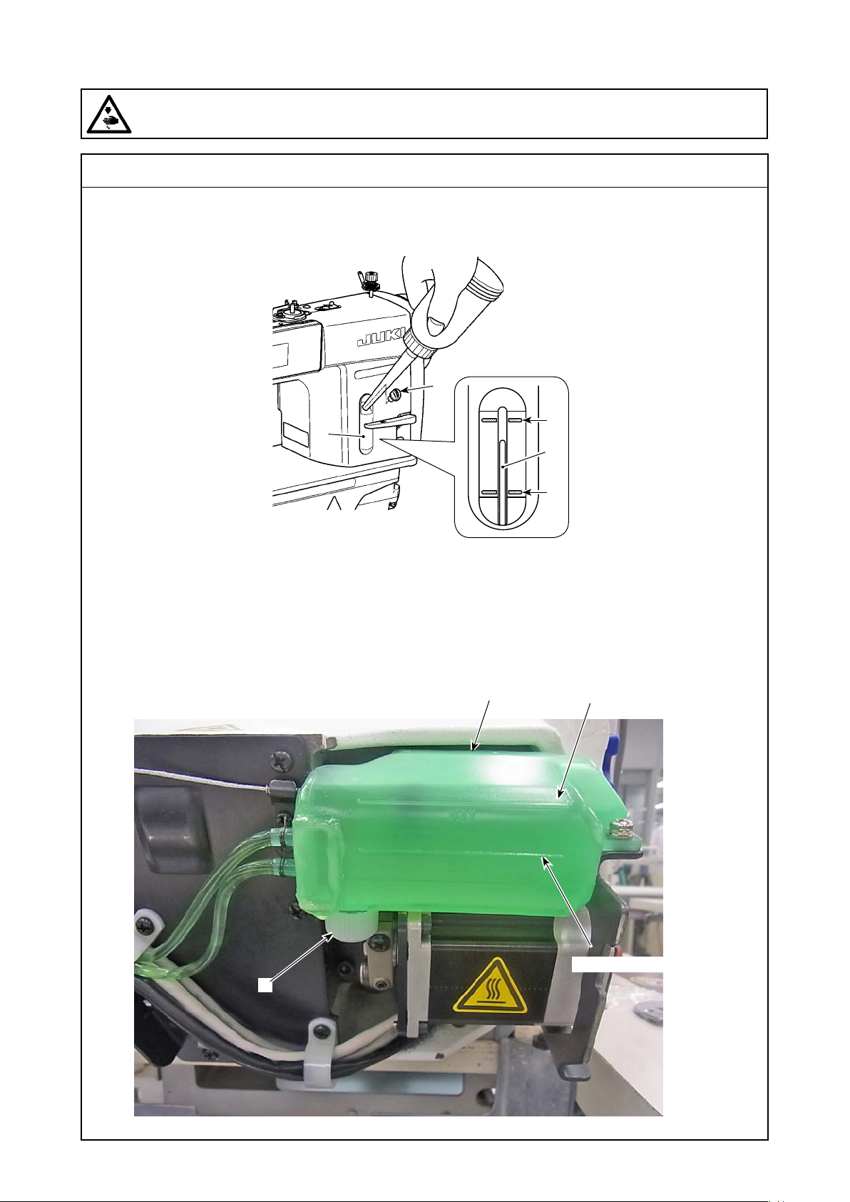
(6) Lubrication
WARNING :
Be sure to turn the power OFF before the following work in order to prevent personal injury due to
unintentional starting of the sewing machine.
Standard adjustment
2) Method of lubrication to the oil tank
❶
❷
3) Method of oil drainage from the oil tank
❺
A
❸
B
Engraved marker line MAX
❹
Engraved marker line MIN
– 16 –
Page 33

Adjustment Procedure
2) Method of lubrication to the oil tank
Fill the oil tank with oil for hook lubrication before operating the
sewing machine.
1. Remove oil hole cap ❶ and ll the oil tank with JUKI NEW DE-
FRIX OIL No.1 (part number : MDFRX1600C0) or JUKI CORPORATION GENUINE OIL 7 (part number : 40102087) using
the oiler supplied with the machine.
2. Fill the oil tank with the oil until the top end of oil amount indi-
cating rod ❸ comes between the upper engraved marker line
A and the lower engraved marker line B of oil amount indicating window ❷.
If the oil is lled excessively, it will leak from the air vent hole in
the oil tank or proper lubrication will be not performed. In addi-
tion, when the oil is vigorously lled, it may overow from the oil
hole. So, be careful.
3. When you operate the sewing machine, rell oil if the top end
of oil amount indicating rod ❸ comes down to the lower engraved marker line B of oil amount indicating window ❷.
(Cautions)1. When you use a new sewing machine or a sewing
machine after an extended period of disuse, use
the sewing machine after performing break-in at
2,000 sti/min or less.
2. For the oil for hook lubrication, purchase JUKI
NEW DEFRIX OIL No. 1 (part number : MDFRX1600C0) or JUKI CORPORATION GENUINE
OIL 7 (part number : 40102087).
3. Be sure to lubricate clean oil.
4. Do not operate the machine with the oil hole cap
❶ removed. Never remove cap ❶ from the oil inlet
in any case other than oiling. In addition, take care
not to lose it.
Results of Improper Adjustment
◦ If too much oil is replenished,
there will be oil leakage from the
air relief hole of the oil tank ❺. In
addition, there can be possibility
of failure in adequate lubrication.
◦ Violent lubrication can result in
overow from the lubrication hole.
3) Method of oil drainage from the oil tank
When carrying the sewing machine or during maintenance ser-
vicing, it is possible to remove the lubricant from the oil tank.
1. Let the sewing machine fall down.
2. Insert the oil pan in the undercover.
3. Turn the oil drain screw ❹ of the oil tank ❺ to drain oil.
4. A maximum of 200ml of oil (to the MAX line) is contained in the
oil tank ❺.
(Cautions)1. Be careful not to forget to tighten the oil drain
screw ❹. Otherwise, this can be a cause of oil
leakage.
2. Do not tighten the oil drain screw ❹ too much.
Otherwise, this can be a cause of oil leakage as a
result of breakage.
– 17 –
◦ Lubricant shall be removed,
without fail, when transporting the
sewing machine.
◦ Due to vibration during transpor-
tation, oil leakage may be caused
through the air relief hole located
on top of the oil tank ❺.
Page 34
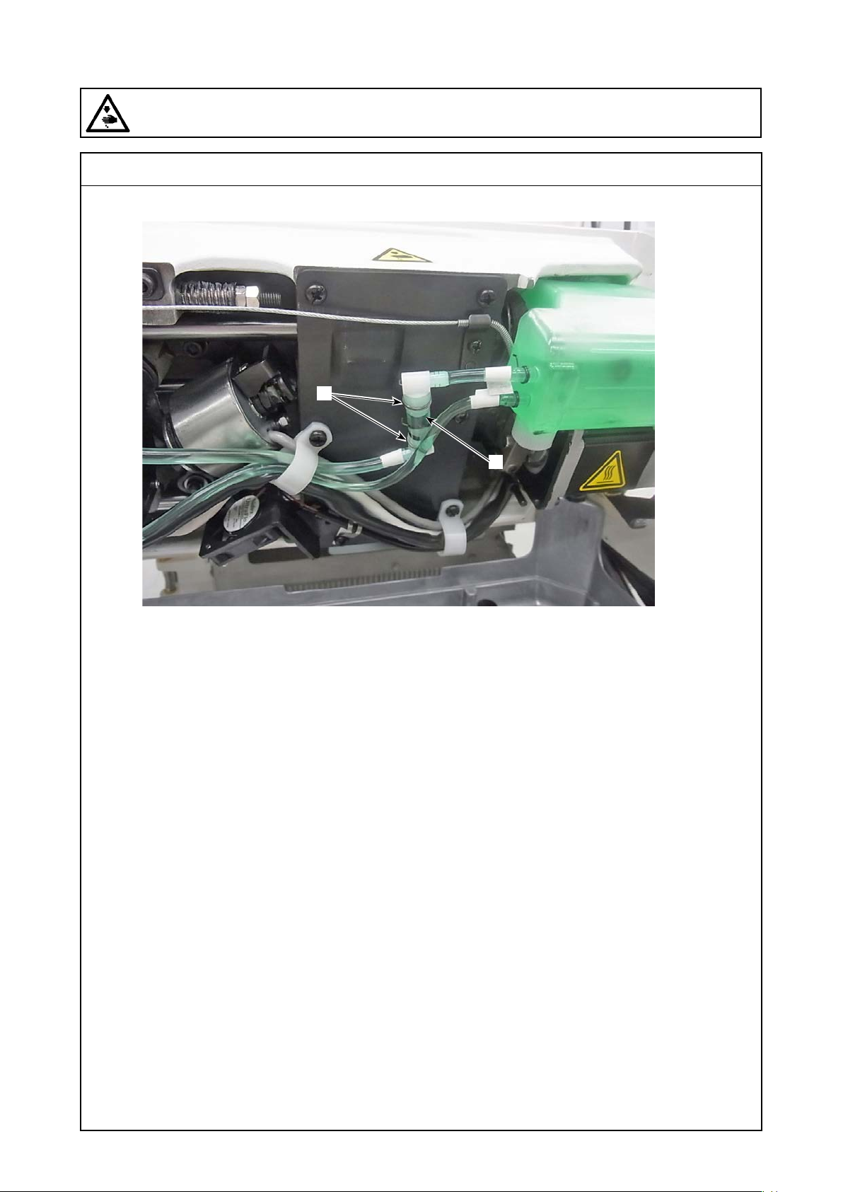
(6) Lubrication
WARNING :
Be sure to turn the power OFF before the following work in order to prevent personal injury due to
unintentional starting of the sewing machine.
4) Cleaning of the oil lter
Standard adjustment
❶
❷
– 18 –
Page 35

Adjustment Procedure
4) Cleaning of the oil lter
Clean the oil lter ❶ periodically (approximately once every three
months).
1. Let the sewing machine fall down.
2. Remove the pipe stop ❶ and then the thread waste attached to
the oil lter ❷.
* Be careful that a lubrication pipe and so on are not damaged at
the time of maintenance of a lter.
Results of Improper Adjustment
◦ If there is clogging in the oil lter
❶, smooth lubrication cannot be
maintained from the lubrication
hole.
– 19 –
Page 36
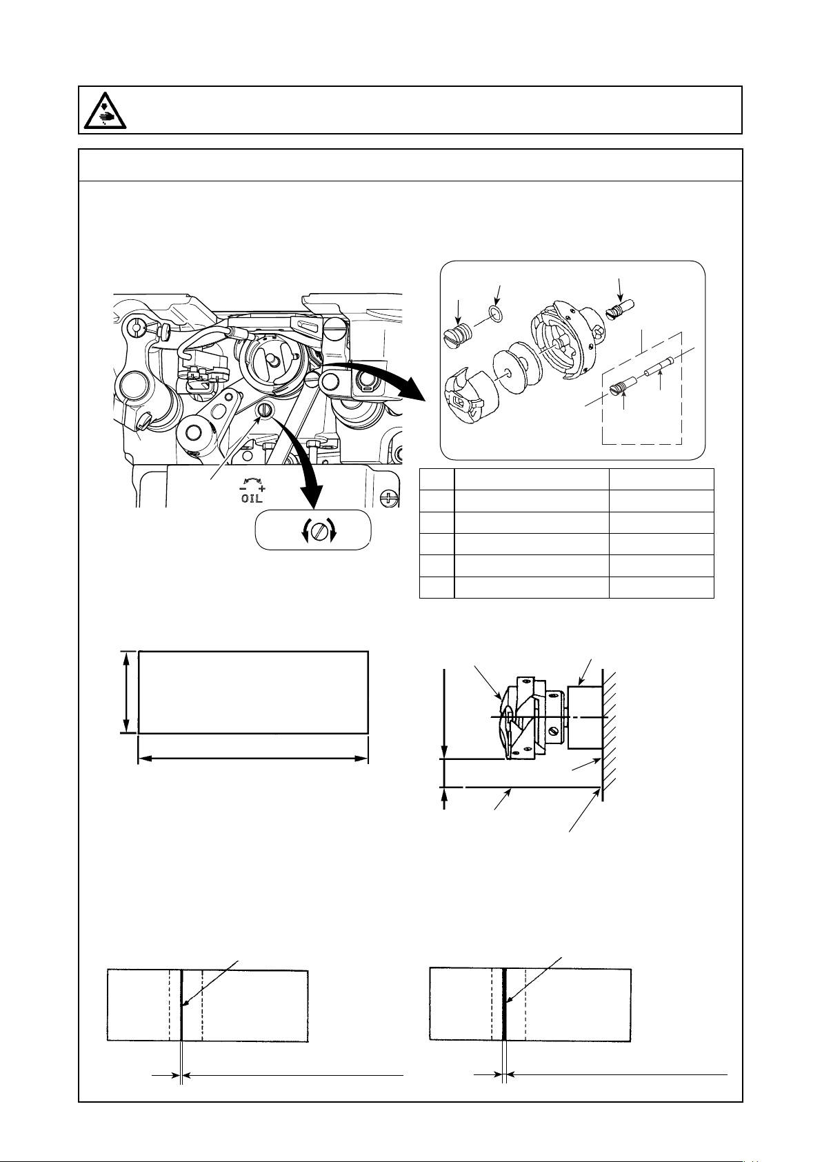
(6) Lubrication
WARNING :
Be sure to turn the power OFF before the following work in order to prevent personal injury due to
unintentional starting of the sewing machine.
Standard adjustment
5) Adjusting the amount of oil in the hook
6) Hook oil adjustment procedures
7) Essentials for hook oil adjustments
8) Replacement of the hook shaft oil wick
❶
Less
Oil quantity (trace) checking paper
Much
❻
❺
DESCRIPTION Part No.
❷
OIL SEAL SCREW ASM.
❸
SET SCREW
❹
OIL WICK
❺
FRONT SCREW
❻
RUBBER RING
Oil quantity (trace) checking paper
Hook
Lower shaft front metal
❷
❷
❹
❸
22916555
22916506
11015906
11079506
RO036080200
Approx. 25mm
Approx. 70mm
* Unnecessary to worry about the quality of paper.
Oil quantity (small)
Oil sprinkles from the hook
• DDL-9000C-SMS : 0.5 to 1mm
• DDL-9000C-SSH : 1 to 3mm
3 to 10mm
Bed
Oil trace checking paper
To be applied to the bed wall.
* Apply the oil quantity (trace) checking paper to hooks
lower side and check it from a distance of 3 to 10mm.
Oil quantity (large)
Oil sprinkles from the hook
• DDL-9000C-SMS : 1 to 1.5mm
• DDL-9000C-SSH : 2 to 4mm
– 20 –
Page 37

Adjustment Procedure
Results of Improper Adjustment
5) Adjusting the amount of oil in the hook
Tighten (turn clockwise) oil amount adjustment screw ❶ to increase the
amount of oil in the hook, or loosen (turn counterclockwise) to decrease it.
(Caution)
[When using RP hook (hook for dry head) for DDL-9000C-SMS type]
1. Remove hook driving shaft oil wick setscrew ❷ and
attach hook driving shaft stopper screw ❸ (part
number : 11079506) and rubber ring ❹ (part number :
RO036080200).
2. Loosen oil amount adjustment screw ❶ up to the minimum so as to reduce the oil amount in the hook. However, do not completely stop the oil and be careful not
to allow oil adjustment screw ❶ to come off.
3. Never drain the oil in the oil tank even when RP hook
(hook for dry head) is used.
6) Hook oil adjustment procedures
1. Tighten the hook oil quantity adjusting screw ❶ to obtain the maximum
oil rate and operate the machine for about 30 seconds.
2. Loosen the oil adjusting screw by two turns and check the quantity of oil.
In this case, give 30 seconds of idling to the sewing machine and measure
the quantity of oil at the intervals of 5 seconds (about 35 seconds in total).
3. According to the quantity of oil secured at that time, determine
the amount of turning for the hook oil quantity adjusting screw ❶.
Give 30 seconds of idling to the sewing machine after re-adjustment and measure the quantity of oil at the intervals of 5 seconds.
4. Adjust the screw position in the procedures of 2. to 3. above until
an adequate quantity of oil has been attained.
(Caution) When the hook is replaced or in the case of the head
(including the heads in a new state) not used for a long
time, it takes about 10 to 20 seconds (4,000sti/min) until
the oil begins to appear from the hook.
The machine stays in the state of causing seizure.
Therefore, use the machine after running-in operation at
2,000sti/min or below.
7) Essentials for hook oil adjustments
1. When the quantity of hook oil is adjusted from excessive oiling
condition to reducing condition (loosening the screw), it is possible to carry out stable adjustments.
2. Check the oil quantity about three times to conrm the stability.
3. If the quantity of oil is too much before adjustments, operate the
machine continuously for about one minute so that the oil attached
to the hook and remaining in the oil path can be ung off completely.
8) Replacement of the hook shaft oil wick
Oil wick ❹ is a consumable item. Periodic replacement is recommended for the stabilization of hook oil quantity.
1. Remove the hook.
2. Remove the set screw ❸.
(Caution) Make sure not to hurt the tip hole of the set screw ❸.
3. Enter a new Oil wick ❹ to the inner part of the set screw ❸ and
then get it around the hook shaft.
◦ When you use an dry hook, buy
and mount the hook driving shaft
stopper screw ❺ and O-ring ❻
that stop the hook oil quantity.
◦ By feeding very much oil, let the
oil prevalent around the hook and
through the lubrication route as a
whole so that the oil path can be
stabilized.
<When the quantity of hook oil is too much>
◦ Too much oil can stain the materi-
als to be sewn.
◦ Oil consumption in the oil tank is
increased.
<When the quantity of hook oil is too less>
◦ The lubrication route tends to be af-
fected easily by factors such as dust.
It is, therefore, necessary to check the
condition of oil quantity periodically.
◦ Under rigorous conditions (operation
at high speed or continuous operation), pay attention to the possible
occurrence of problems such as hook
seizure and thread breakage by heat.
◦ If a contaminated oil is used, lter
clogging occurs earlier and this can
be a cause of unstable oil quantity.
– 21 –
Page 38
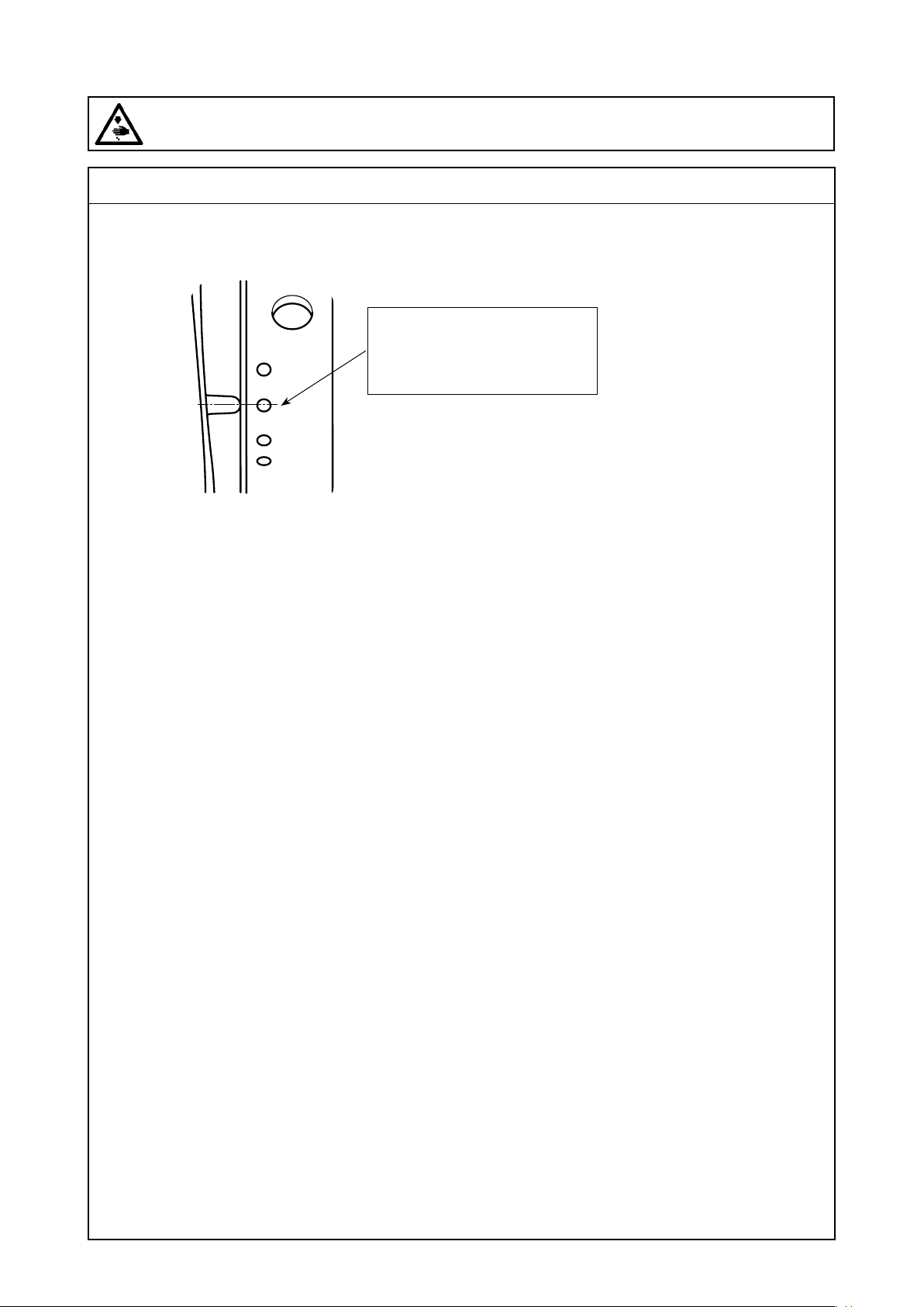
(7) Various origin adjustments
WARNING :
Be sure to turn the power OFF before the following work in order to prevent personal injury due to
unintentional starting of the sewing machine.
Standard adjustment
1) Z-phase adjustment of a main motor
Turn a handwheel one revolution,
align one marker line with the
other marker line, and press the
❺ button to x it.
– 22 –
Page 39
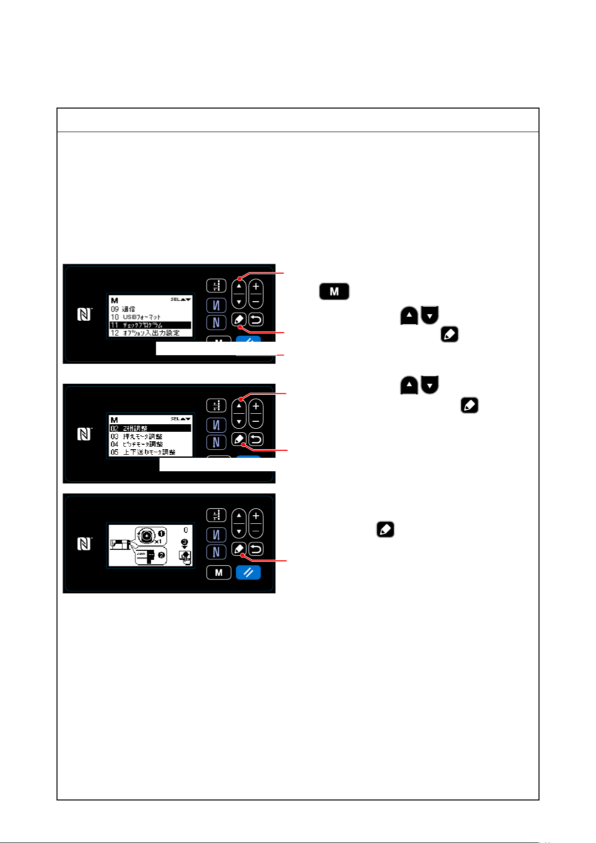
Adjustment Procedure
1) Z-phase adjustment of a main motor
* When you implement an origin adjustment of various motors, be sure to start with adjustment of a
main motor (Z-phase adjustment).
It is because the phase of various motors is decided by the angle of the main motor.
* For adjustment of various motors, refer to the Section "11 Check program."
The procedure conforms to 1) Z-phase adjustment of a main motor.
1)-1. DDL-9000C-S
1. Turn on the sewing machine while pressing the
❶
❾.
2. After pressing the ❶ to select the "11
画面をご支給ください
❺
❾
❶
Check program," press the ❺ to display the
check program selection screen.
3. After pressing the ❶ to select the "02
Z-phase adjustment," press the ❺ to dis-
play the Z-phase adjustment screen.
画面をご支給ください
❺
4. Turn a handwheel one revolution and align
one marker line with the other marker line. By
pressing the ❺, the current screen returns
to the check program election screen after the
❺
adjusted contents are xed.
– 23 –
Page 40
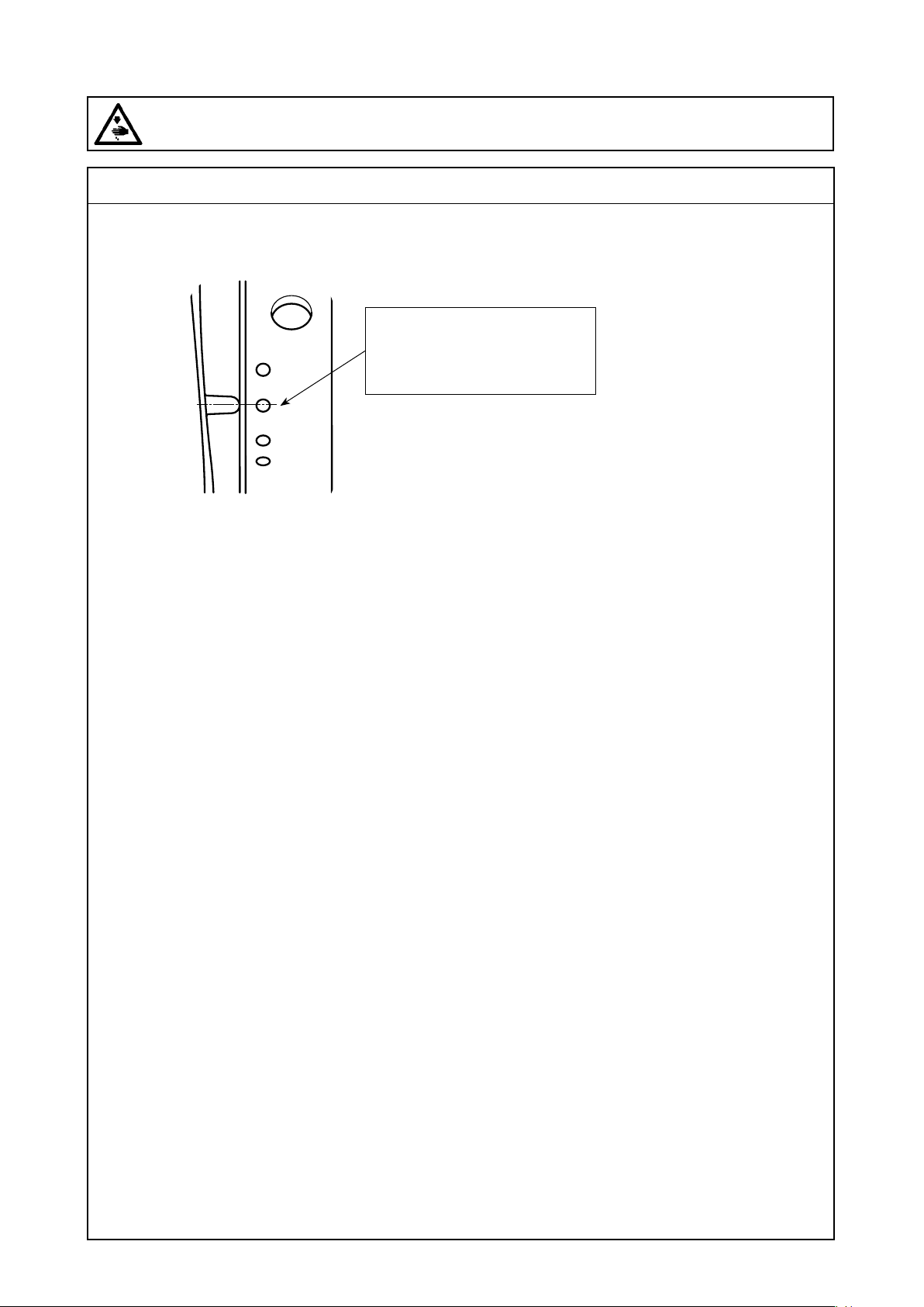
(7) Various origin adjustments
WARNING :
Be sure to turn the power OFF before the following work in order to prevent personal injury due to
unintentional starting of the sewing machine.
Standard adjustment
1) Z-phase adjustment of a main motor
Turn a handwheel one revolution,
align one marker line with the
other marker line, and press the
❺ button to x it.
– 24 –
Page 41
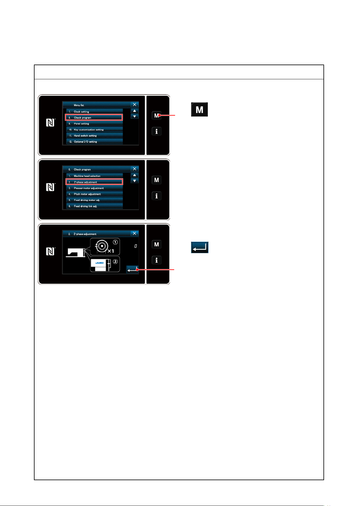
1)-2. DDL-9000C-F
Adjustment Procedure
1. Turn on the sewing machine while pressing the
❶
Press the check program key to display the
2. Press the Z-phase adjustment key to display the
3. Turn a ywheel one revolution, align one marker
❸
❶.
check program selection screen.
Z-phase adjustment screen.
line with the other marker line, and press the
❸ to x it.
– 25 –
Page 42
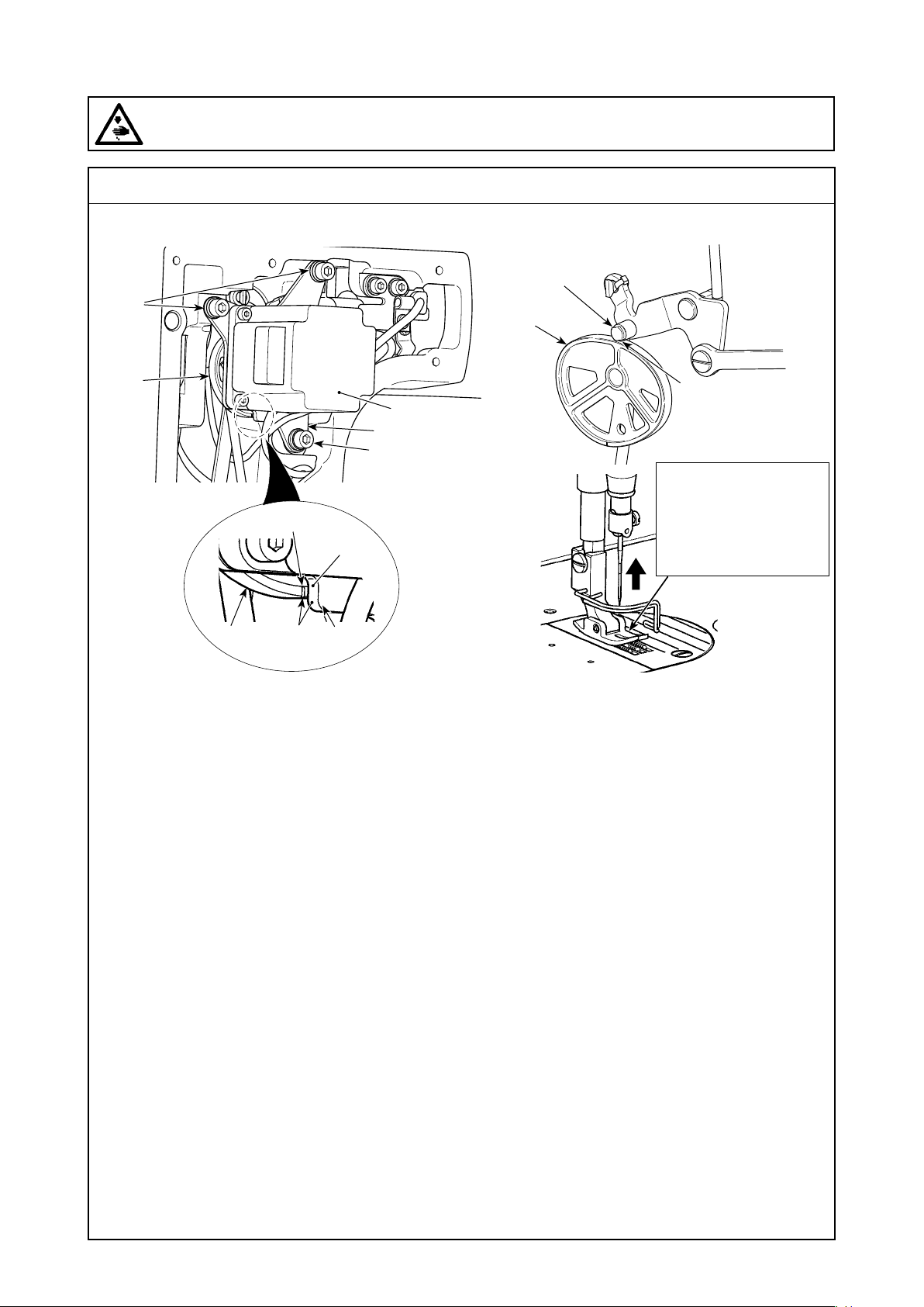
(7) Various origin adjustments
WARNING :
Be sure to turn the power OFF before the following work in order to prevent personal injury due to
unintentional starting of the sewing machine.
Standard adjustment
2) Adjustment of the origin of a presser lifter motor
A
Collinear
❾
B
❾
Light-contact state
If the cam roller is
raised, the problem that
the presser foot sole
fails to come in contact
with the throat plate can
occur.
There is a marker line on the surface of cam .
Adjust so that marker line A on the cam and end face B of motor xing plate ❾ are collinear to each other.
* Do not disassemble the cam and the motor since their origin positions have been factory-
adjusted appropriately at the time of delivery.
Securely tighten three presser motor asm. setscrews while bringing cam roller and cam into light contact with each other.
– 26 –
Page 43
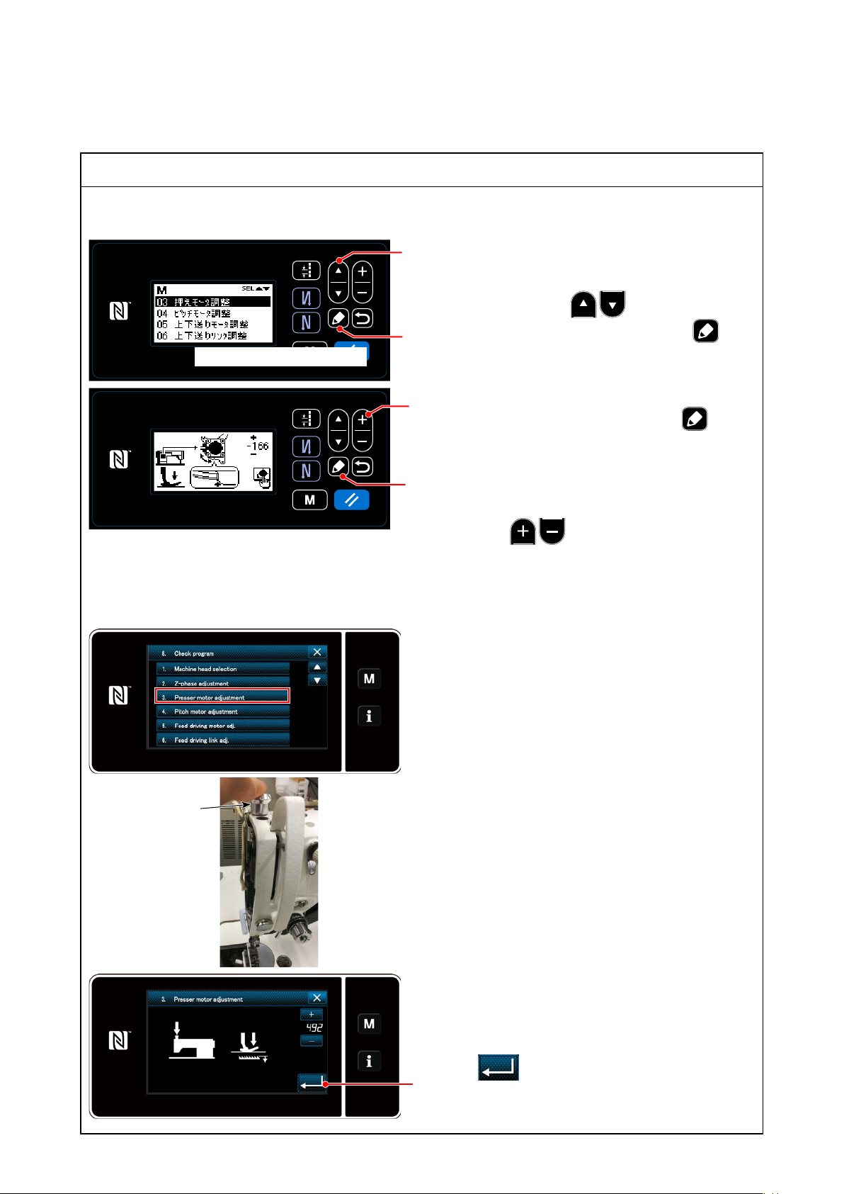
Adjustment Procedure
2) Adjustment of the origin of a presser lifter motor
2)-1. DDL-9000C-S
画面をご支給ください
2)-2. DDL-9000F-S
❶
1. Just like the 1. of 1)-1, open the check program
list screen.
2. After pressing the ❶ to select the "03
❺
Presser motor adjustment," press the ❺ to
display the Presser motor adjustment screen.
3.
Align one marker line on the cam with the other
marker line and keep the presser foot in contact
❷
with the throat plate. By pressing the ❺, the
current screen returns to the check program elec-
tion screen after the adjusted contents are xed.
* When marker lines of a cam are not aligned
❺
with each other, adjust a cam slightly by press-
ing the ❷.
* For detailed adjustment method and so on,
refer to the AK-154 Instruction Manual.
1. Just like the 1. of 1)-2, open the check program
list screen.
2. Make sure that the presser bar moves freely up
and down, and press the presser bar cap ❶ in
the upper part in a state where the presser foot
has been attached.
❶
3. By pressing the presser motor adjustment key
in a state where the presser bar cap ❶ in the
upper part has been pressed, the presser lifter
motor origin adjustment screen is displayed.
4. In a state where one marker line on the cam
aligns with the other marker line and the cam is
in contact with the presser throat plate, press
the ❸ to x it.
❷
– 27 –
Page 44
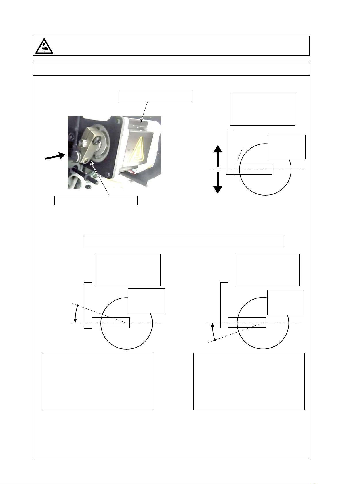
(7) Various origin adjustments
WARNING :
Be sure to turn the power OFF before the following work in order to prevent personal injury due to
unintentional starting of the sewing machine.
Standard adjustment
3) Pitch motor adjustment
Horizontal feed pulse motor
A direction
Horizontal feed pulse motor link
(Caution) When the horizontal feed motor link is
positioned at 90 degrees, the horizontal feed
amount is zeroed.
Fragmentary view taken in the A direction of an arrow (conceptual drawing)
Figure 2
Conceptual drawing
of input to a horizontal
feed pulse motor
0 Origin
+ Pitch
− Pitch
Figure 1
Conceptual drawing of
the origin of a horizontal
feed pulse motor
90°
Conceptual drawing
of input to a horizontal
feed pulse motor
Horizontal
feed pulse
motor
Figure 3
0 Origin
To nally 90 °
When it has got in a slight forward feed
motion,
The horizontal feed link is as shown in the
Figure 2 and is slightly upward from the
position of 90 degrees. Correct the position
by a minus one pulse and conrm the feed
by 0 degrees.
+
−
Horizontal
feed pulse
motor
Horizontal
feed pulse
motor
To nally 90 °
+
0 Origin
−
When it has got in a slight forward feed
motion,
The horizontal feed link is as shown in the
Figure 3 and is slightly upward from the
position of 90 degrees. Correct the position
by a minus one pulse and conrm the feed
by 0 degrees.
– 28 –
Page 45
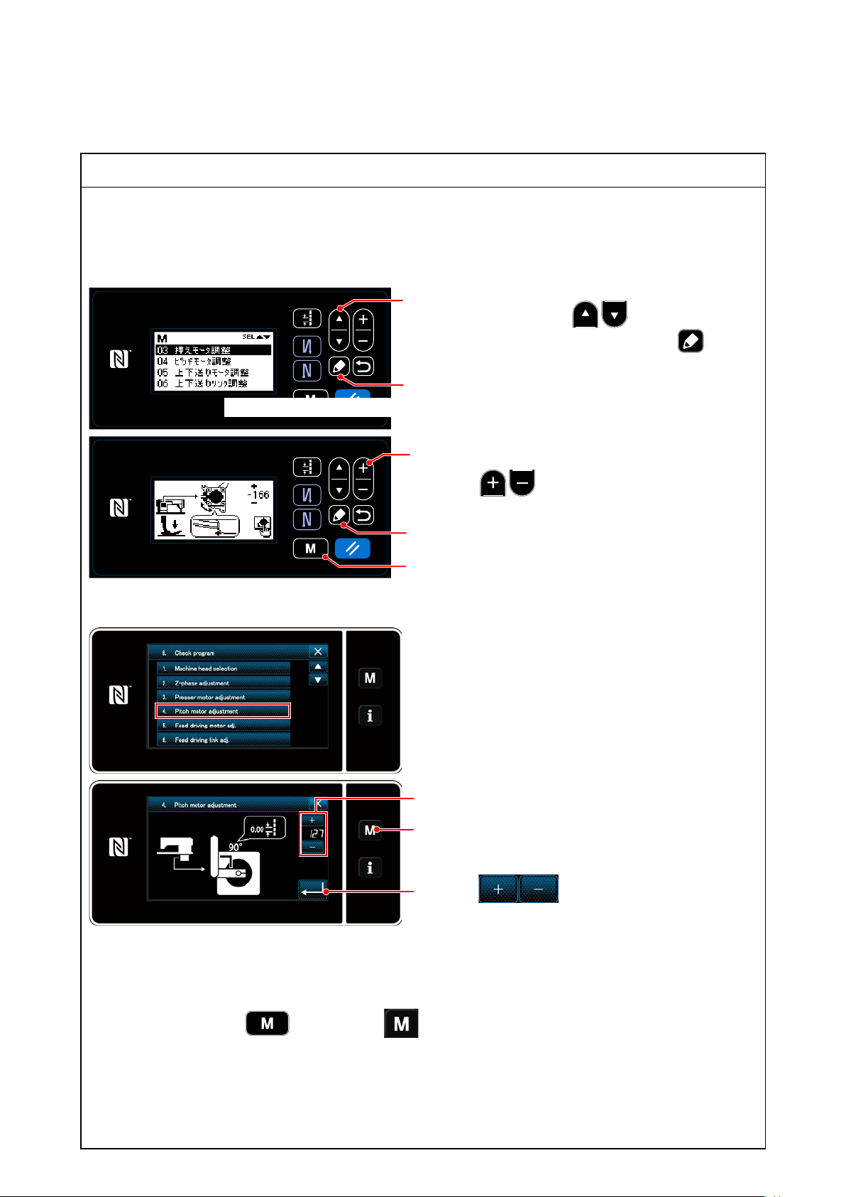
Adjustment Procedure
3) Pitch motor adjustment
* The pitch motor adjustment is helpful to adjust the origin of a horizontal motor that controls the horizon-
tal feed motion.
3)-1. DDL-9000C-S
3)-2. DDL-9000F-S
画面をご支給ください
1. Just like the 1. of 1)-1, open the check program
❶
list screen.
2. After pressing the ❶ to select the "03
Pitch motor adjustment," press the ❺ to
display the Presser motor adjustment screen.
3. Conrmation of a horizontal feed motor link
❺
* When the horizontal feed motor link is po-
sitioned at 90 degrees, the horizontal feed
amount is zeroed.
❷
Correct the feed amount by one pulse by pressing
the ❷ according to the feed direction.
4. Turn on the sewing machine again and set the
❺
❾
pitch to 0.0mm, and make sure that the feed
(amount) is a zero when the sewing machine
runs at low speed.
* The feed (amount) is not a zero, perform opera-
tion again from ①.
1. Just like the 1. of 1)-2, open the check program
list screen.
2. After pressing the "Pitch motor adjustment key"
to display the Pitch motor adjustment screen.
3. Conrmation of a horizontal feed motor link
❷
* When the horizontal feed motor link is po-
sitioned at 90 degrees, the horizontal feed
❶
amount is zeroed.
Correct the feed amount by one pulse by pressing
the ❷ according to the feed direction.
⇒ When you have performed the inching operation (200 rotations) again after correction, conrm that the
feed amount is zero. (This is a repeated operation.)
(Caution) When you have replaced the horizontal feed motor because of a trouble and the like, the
motor itself does not recognize its origin. Be sure to enter "11 Check program" while
pressing the ❾ (S type) or ❶ (F type), and turn on the sewing machine.
* When the origin is deviating largely such as after replacement of a motor, x a horizontal
feed motor link at approximately 90 degrees by hand. Then, turn a handwheel by hand,
make sure of the position where that paper is not fed, and operate it.
When you turn on the sewing machine and get into the feed motion in the state of zeroed
feed amount and with the inching operation, make an adjustment of the origin again in
accordance with the above procedure 1.
– 29 –
Page 46
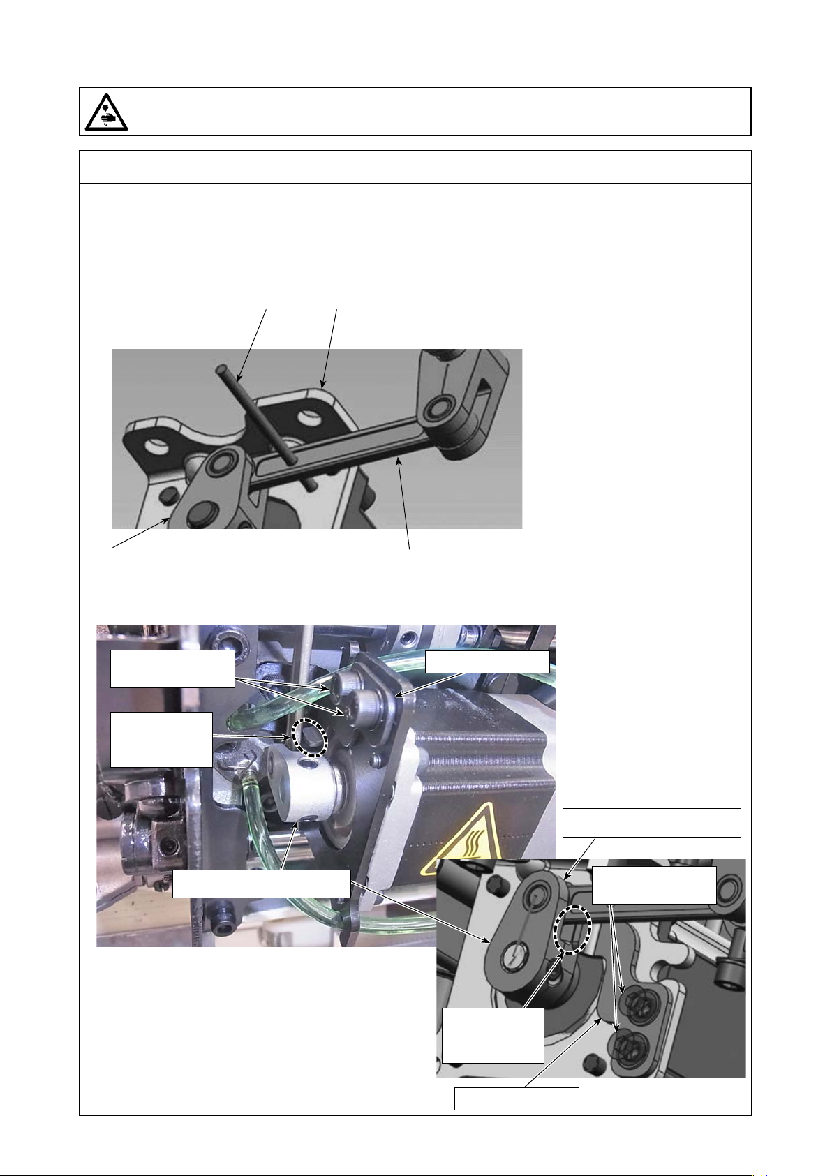
(7) Various origin adjustments
WARNING :
Be sure to turn the power OFF before the following work in order to prevent personal injury due to
unintentional starting of the sewing machine.
Standard adjustment
4) Vertical feed motor adjustment
Round bar of φ 3
Upper and lower motor link
Vertical feed pulse motor base
Upper and lower connection link
4-3) Vertical feed motor link stopper adjustment
Feeder bar stopper
adjustment screw
Feeder bar stopper
(Caution) Make the hole on
the side of the upper and
lower connection link co-
incide with the hole of the
origin (a reference pin) of a
motor base.
* Recommended referenced
pin with a round bar
of φ 3
0
-0.05
Part number : 12108106
(Caution) φ3丸棒が入らない場
合は 入 るように削って
ください。
Parallel
assembly with
a gap of 0.2mm
Upper and lower motor link
In a state where the hole of the origin (a reference pin)
coincides with each other, fasten the upper and lower
motor link and the side of the feeder bar stopper with
feeder bar stopper adjustment screws while keeping 0.2
mm distance between them.
* Fasten the tip section of a feeder bar stopper in par-
allel with the side of the upper and lower motor link.
Upper and lower motor link
Feeder bar stopper
adjustment screw
Parallel
assembly with
a gap of 0.2mm
Feeder bar stopper
– 30 –
Page 47
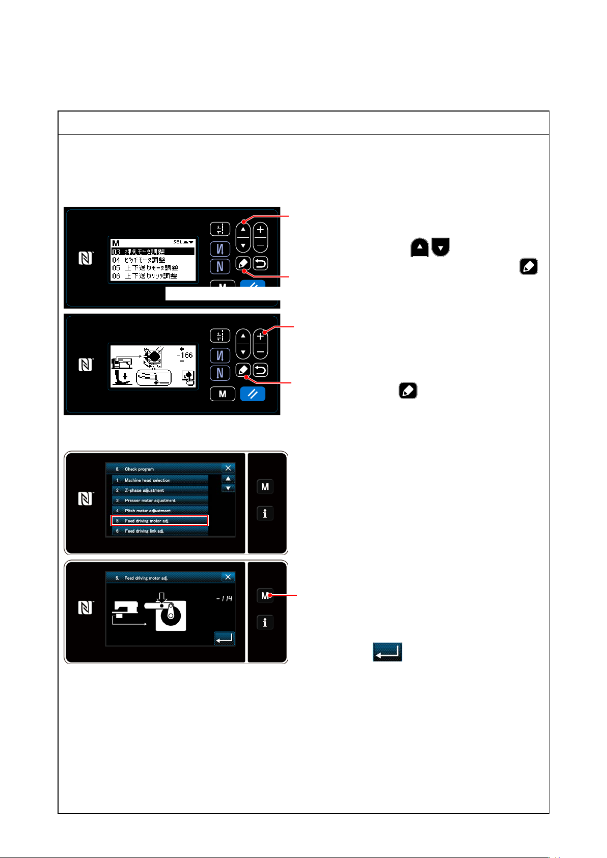
Adjustment Procedure
4) Vertical feed motor adjustment
* The vertical feed motor adjustment is helpful to adjust the origin of the vertical feed motor adjustment
that controls the vertical feed motion.
4)-1. DDL-9000C-S
1. Just like the 1. of 1)-1, open the check program
❶
list screen.
2. After pressing the ❶ to select the "05
Vertical feed motor adjustment," press the
❺
画面をご支給ください
❷
❺
❺ to display the Presser motor adjustment
screen.
3. Make the hole (of the origin) on the side of the
upper and lower connection link coincide with
the hole of a motor base.
* The state of coinciding with each other shall
become the origin of the horizontal feed motor.
4.
By pressing the ❺, the current screen re-
turns to the check program election screen after
the adjusted contents are xed.
4)-2. DDL-9000F-S
4-3) Vertical feed motor link stopper adjustment
* The vertical feed motor link stopper serves as a regulated part that prevents damage of parts such as
the thread trimmer by lowering a feeder bar when maintenance work such as replacement of a feed
dog is performed at the time of power-off.
When you have implemented an adjustment of the origin, be sure to make this adjustment.
1. Just like the 1. of 1)-2, open the check program
list screen.
2. After pressing the "Vertical feed motor adjust-
ment key" to display the Vertical feed motor
adjustment screen.
3. Make the hole (of the origin) on the side of the
❶
upper and lower connection link coincide with
the hole of a motor base.
* The state of coinciding with each other shall
become the origin of the horizontal feed motor.
4. Press the ❸ to x it.
– 31 –
Page 48
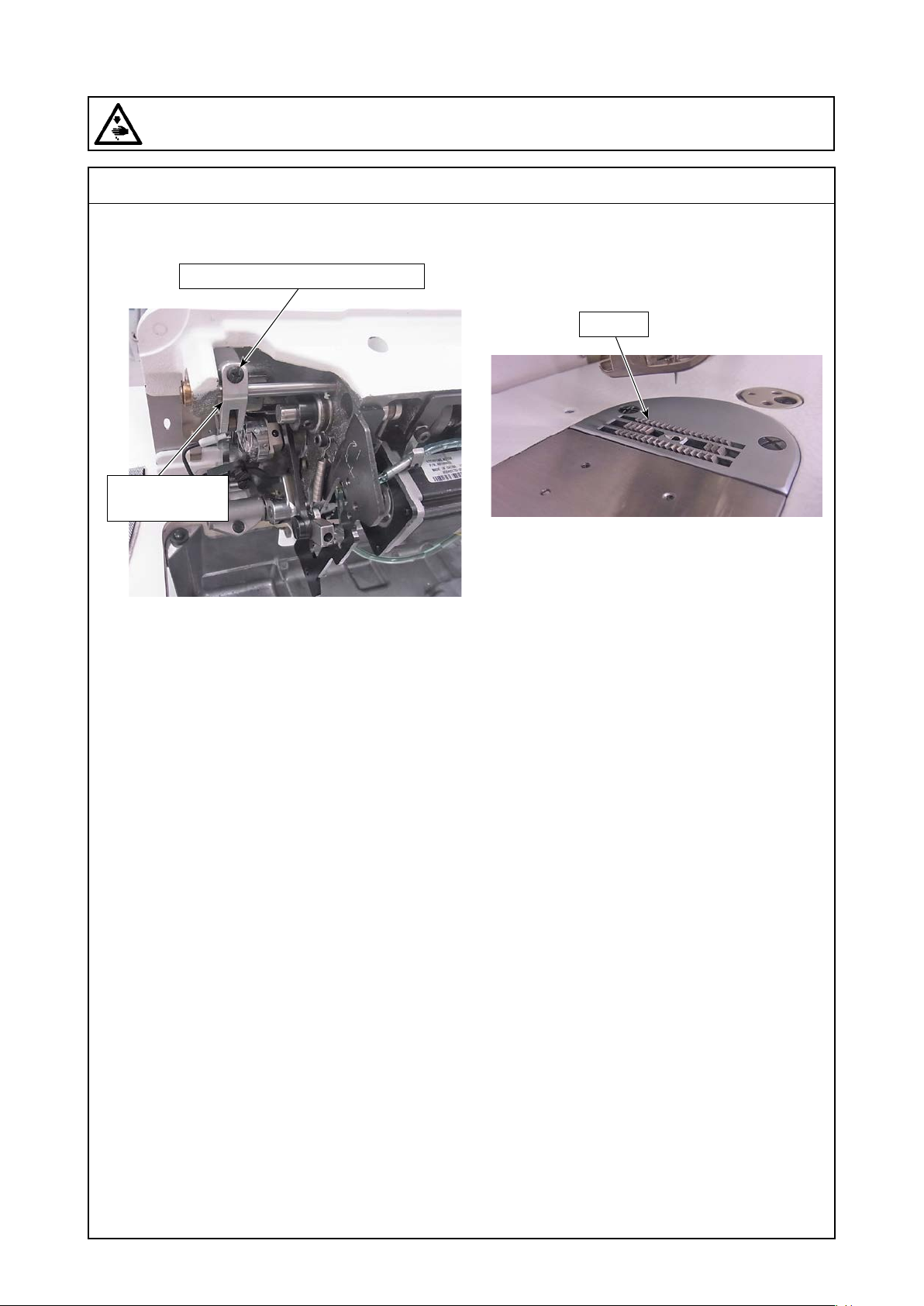
(7) Various origin adjustments
WARNING :
Be sure to turn the power OFF before the following work in order to prevent personal injury due to
unintentional starting of the sewing machine.
5) Vertical feed link adjustment
Upper and lower link arm setscrew
Upper and lower
link arm
Standard adjustment
Feed dog
It is the height of a feed dog from the surface of
a throat plate.
* Remove the presser and do not apply the
presser pressure.
– 32 –
Page 49
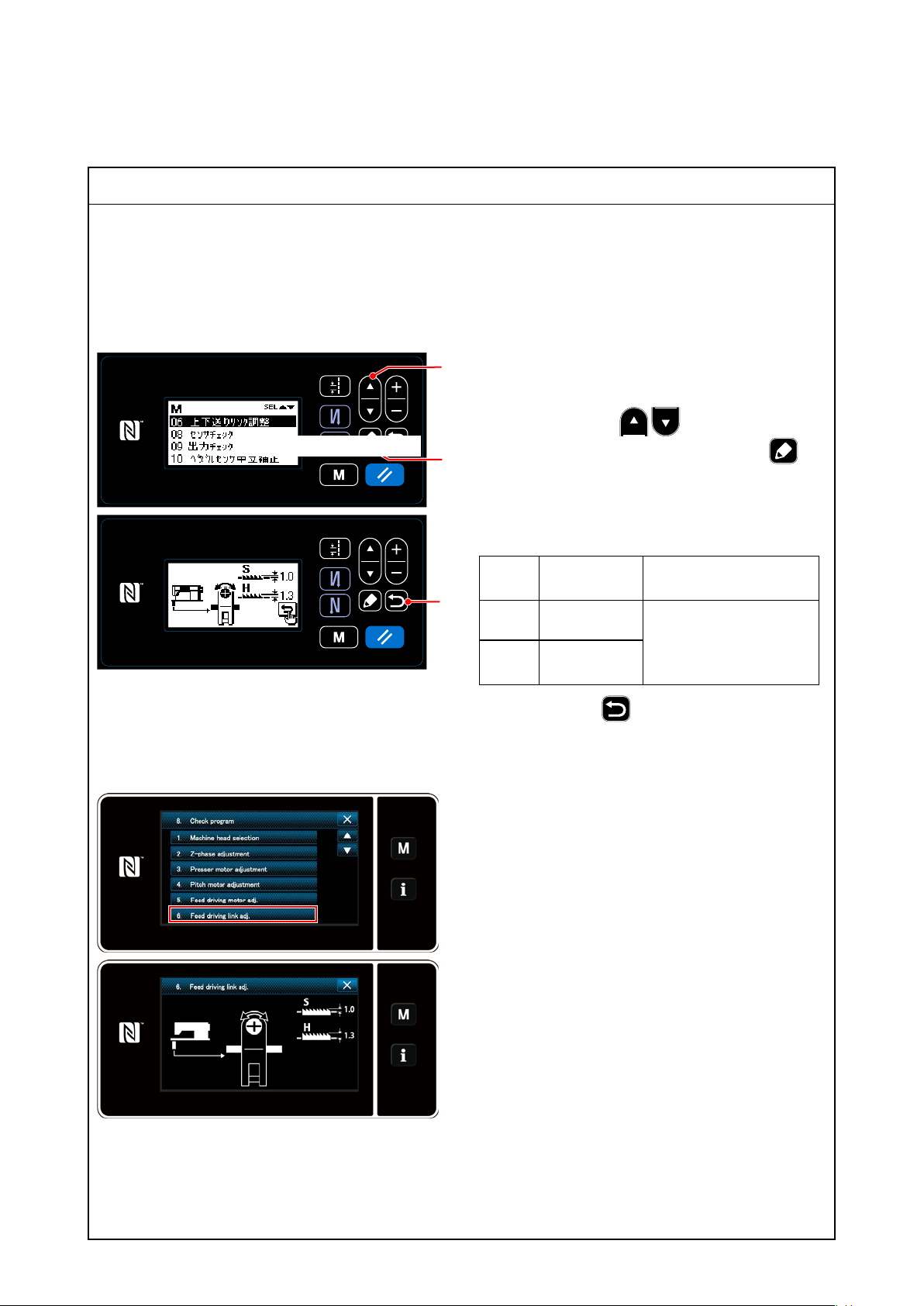
Adjustment Procedure
5) Vertical feed link adjustment
* The vertical feed link adjustment is helpful to adjust the height of a feed dog at a maximum by produc-
ing the biggest possible uctuations in the vertical feed motor.
* Assemble a feed dog in a state of no presser pressure.
* The feed locus motion considering the presser pressure is seen in the actual sewing process.
5)-1. DDL-9000C-S
❶
1. Just like the 1. of 1)-1, open the check program
list screen.
2. After pressing the ❶ to select the "06
画面をご支給ください
❺
❻
Vertical feed link adjustment," press the
❺ to display the Vertical feed link adjustment
screen.
3. If the height of a feed dog is decided, tighten the
upper and lower link arm setscrew.
type 1.0
S
H type 1.3
Height of a
feed dog
mm
mm
The value for assembly
is available when a value
displayed on the operation panel is 0.
Remark
5)-2. DDL-9000F-S
4.
By pressing the
turns to the check program election screen after
the adjusted contents are xed.
1. Just like the 1. of 1)-2, open the check program
list screen.
2. After pressing the "Vertical feed link adjustment
key" to display the Vertical feed motor adjust-
ment screen.
3. Conrmation of the upper and lower motor link
4. If the height of a feed dog is decided, tighten the
upper and lower link arm setscrew.
❻
, the current screen re-
– 33 –
Page 50
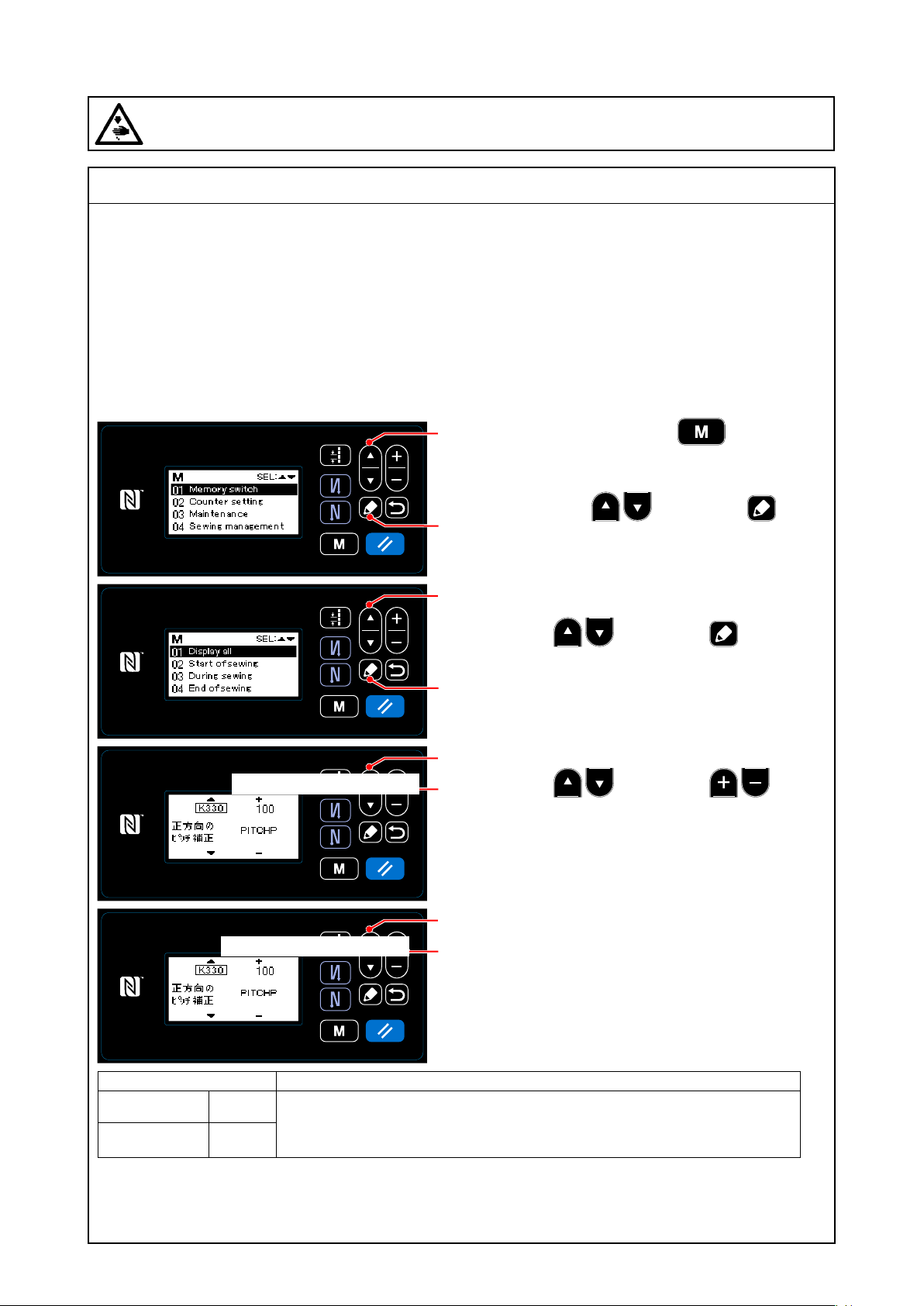
(7) Various origin adjustments
WARNING :
Be sure to turn the power OFF before the following work in order to prevent personal injury due to
unintentional starting of the sewing machine.
Standard adjustment
6) Adjustment of forward reverse stitches (correction function)
After adjustments described from the above 1) through 5) are completed, check a numerical scale dis-
played on the operation panel and an actual needle-entry. When you set a numerical value to 3 on the
operation panel, put paper under the presser and check a needle-entry pitch with an inching motion (It is
driven at 200 rotations.) . When the needle-entry pitch is more or less than 3 of the numerical scale, make
an adjustment to correct the pitch.
* Even if you have made a pulse motor adjustment, variation in the sewing machines occurs because
of quality of a gauge and so on.
6)-1. DDL-9000C-S
画面をご支給ください
1. When you hold down the ❾ for six sec-
❶
onds, a mode screen is displayed.
2. After selection of the "01 Memory switch" by
pressing the ❶, press the ❺n to
❺
❶
❺
❶
❷
display the memory switch classication selec-
tion screen.
3. After selection of the "01 Display All" by press-
ing the ❶, press the ❺ to display
the memory switch settings screen.
4. After selection of the K330 and K331 by press-
ing the ❶, press the ❷ to
perform a pitch correction.
❶
画面をご支給ください
Correction Remarks
Forward pitch K330
Reverse pitch K331
* After adjustment, there may be a gap in the display of a scale and in a needle-entry, depending on the
sewing products.
In this case, adjust it with the scale displayed on the panel.
* The pitch is corrected considering the present value as 100%.
* Aim at 100% adjustment of the pitch against forward reverse 100% and a
numerical value displayed on the operation panel.
❷
– 34 –
Page 51
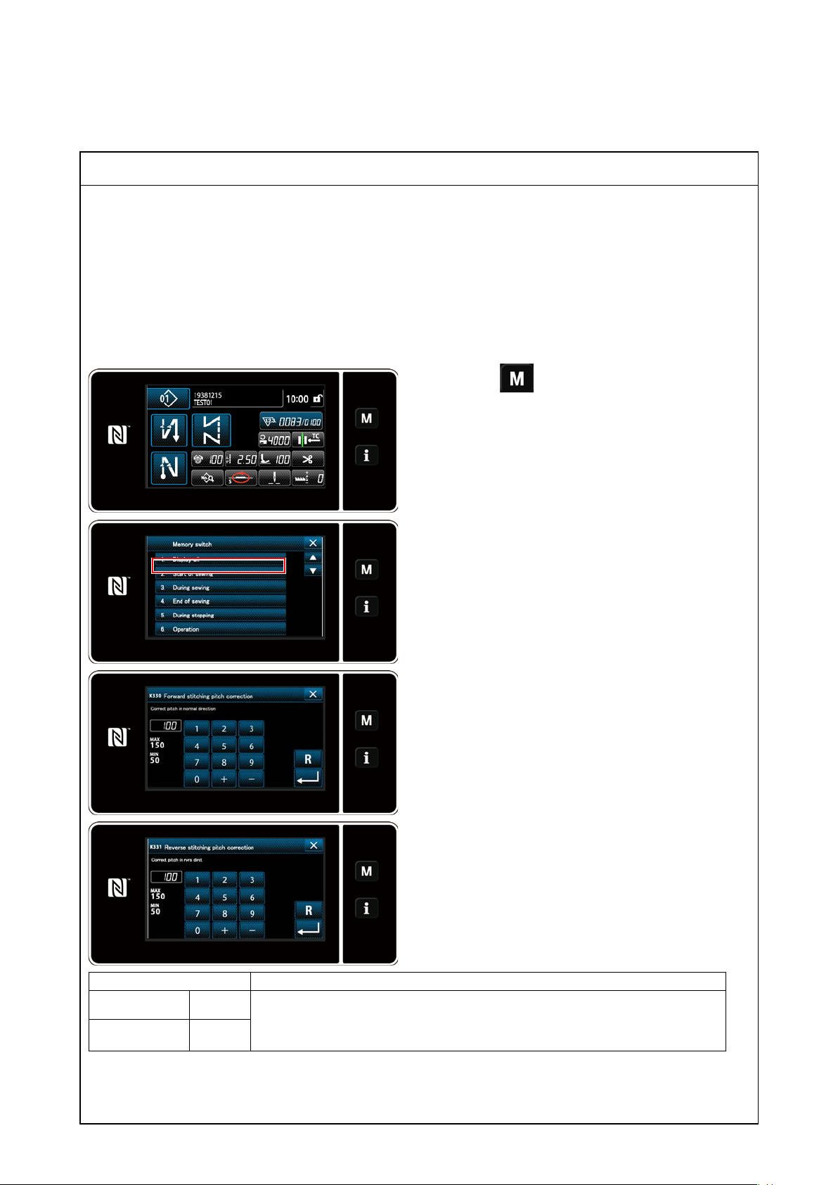
Adjustment Procedure
6)-2. DDL-9000F-S
1. Press ❾ on the sewing screen to display
the mode screen.
2. After selection of the "01 Memory switch", and
selection of the "1. Display All".
3. After selection of the "K330 Forword stitching
pitch correction" and "K331 Reverse stitching
pitch correction" to perform a pitch correction.
* After adjustment, there may be a gap in the dis-
play of a scale and in a needle-entry, depending
on the sewing products.
In this case, adjust it with the scale displayed
on the panel
Correction Remarks
Forward pitch K330
Reverse pitch K331
* The pitch is corrected considering the present value as 100%.
* Aim at 100% adjustment of the pitch against forward reverse 100% and a
numerical value displayed on the operation panel.
– 35 –
Page 52
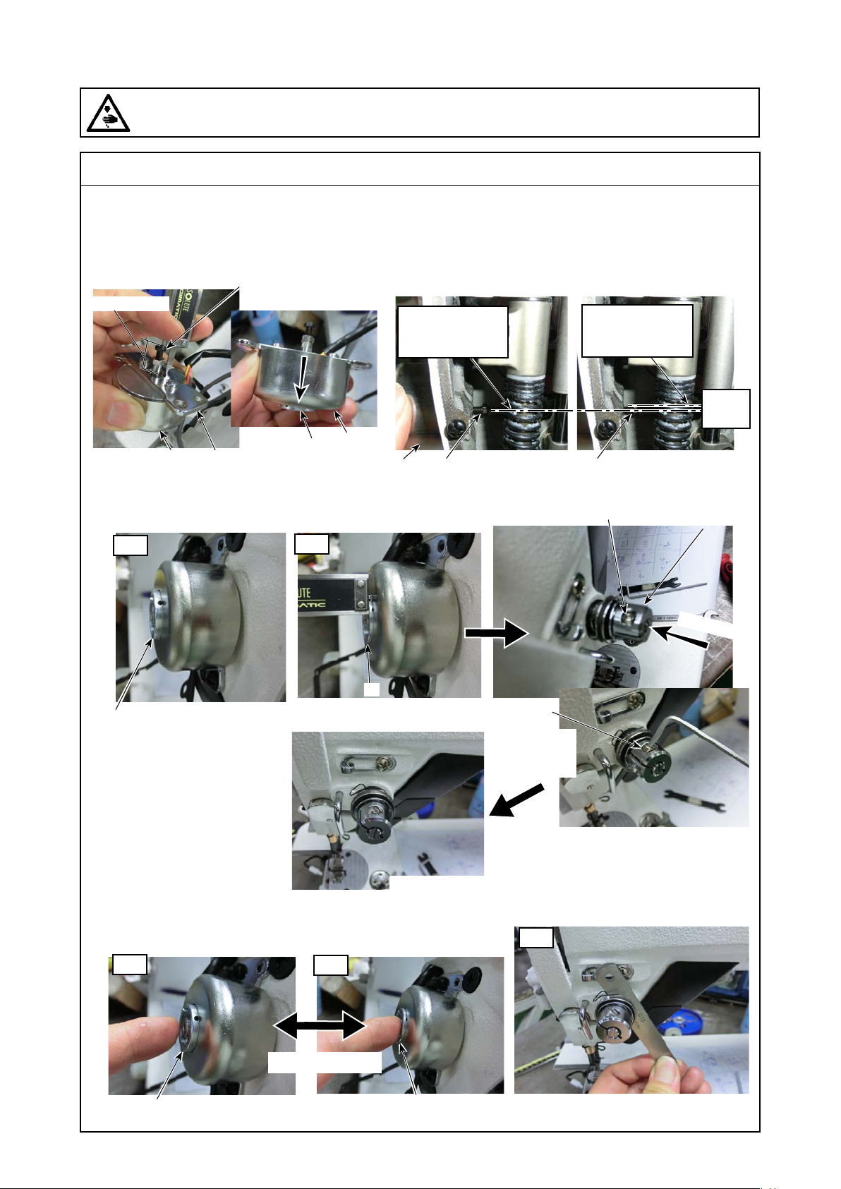
(7) Various origin adjustments
WARNING :
Be sure to turn the power OFF before the following work in order to prevent personal injury due to
unintentional starting of the sewing machine.
Standard adjustment
7) Adjustment of active tension (only the DDL-9000C-F)
❸
19±0.1mm
OK
The shaft center
is in alignment.
❶
❶
❹
❷
❶
❸ ❸
NG
The shaft center is
out of alignment.
Thread
tension
❷
OFF
ON
❷
Set the height of a convex
portion to 1.5 ± 0.1 mm.
<Completion>
❺
* Attach it in
the right
direction.
❺
❻
Press lightly
OFF
❷
ON
To return smoothly
❷
– 36 –
OFF
To have a gap of 1 mm or more in
the (thread tension) disk
Page 53

Adjustment Procedure
7) Adjustment of active tension (only the DDL-9000C-F)
1. Assembly
Assemble the active tension in the following way.
1). Sub assembly
Attach the screw (M4) ❸ to the plunger ❷ of the AT solenoid ❶.
At this time, keep 19 ± 0.1 mm from the upper surface of the
xed plate ❹ to the upper portion of the screw ❸ and a nut
torque of 25± 5kgcm.
(Cautions)1. Put the plunger ❷ in a state of being lowered.
2. Use the plunger ❷ that falls under its own
weight. Do not use a torque plunger.
2). Complete assembly
○ Positioning of the solenoid
Align the shaft center of the thread tension with that of the AT
solenoid ❶ at the time of attachment of the AT solenoid ❶.
(After assembling the thread tension, attach the AT solenoid ❶.
Check the shaft center instead of the surface portion.)
(Cautions)When the shaft center is out of alignment, the shaft
becomes worse at the time of pressurization with the
AT solenoid ❶ and the regular value becomes dif-
cult to come out.
○ Relation between the plunger and the (thread tension) disk.
Put the convex portion of the plunger ❷ in a state where it
comes out of the surface of the AT solenoid ❶ by 1.5 ± 0.1 mm.
Loosen the thread tension cap setscrew ❺ to press the thread
tension cap ❻ lightly.
Tighten the thread tension cap setscrew ❺.
Results of Improper Adjustment
(Cautions) 1. Position the thread tension cap setscrew ❺ in
the right direction. When it is positioned on the
left side, there is a possibility that it interferes
with thread.
2. After assembly, press the plunger ❷ to make
sure that the thread tension disk does not move
(not revolve).
3). Conrmation of assembly quality
Make sure that the plunger ❷ returns smoothly at the time of
pressing it lightly.
When the plunger ❷ is OFF, make sure that there is a gap of 1
mm or more in the (thread tension) disk.
If the gap is not 1 mm or more, it becomes necessary to adjust
19±0.1mm as an assembly value.
– 37 –
Page 54
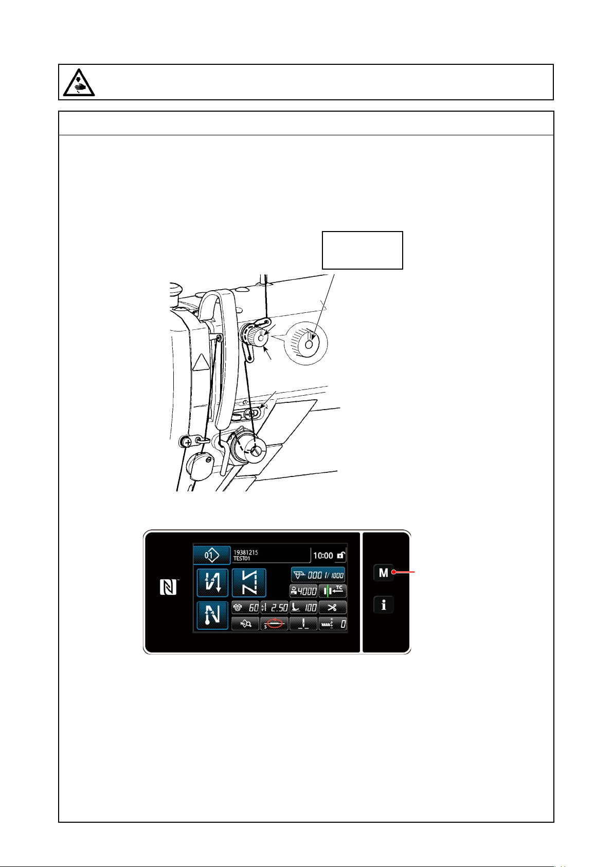
(7) Various origin adjustments
WARNING :
Be sure to turn the power OFF before the following work in order to prevent personal injury due to
unintentional starting of the sewing machine.
Standard adjustment
7) Adjustment of active tension (only the DDL-9000C-F)
(Cautions) Be sure to take a measure to prevent variation between the sewing machines.
2. Correction for tension
1) Conrmation of the current state
The screw ❶ and
the nut ❷ are on
the same plane.
❷
❶
❹
* The Gunze span #60 is used for thread.
* Let the thread take-up spring and the
thread guide through.
❾
* Set the thread tension on the panel to 60.
– 38 –
Page 55
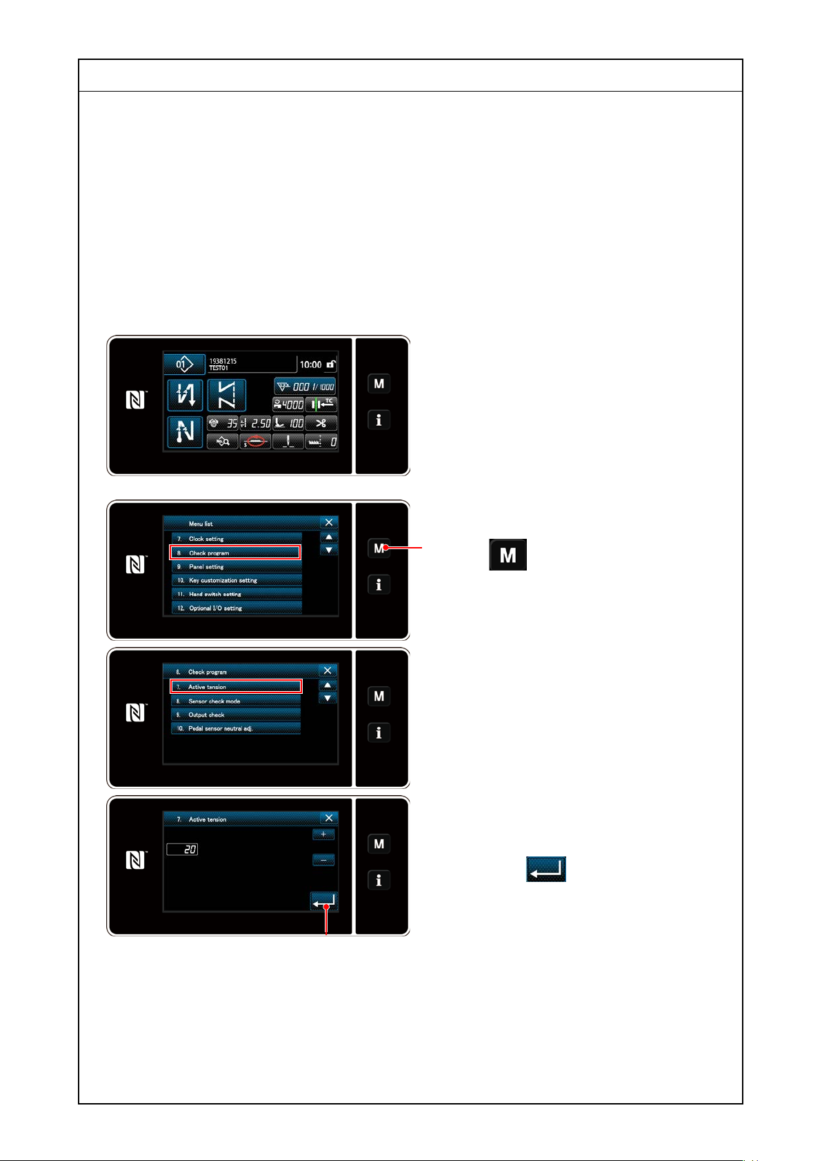
Adjustment Procedure
2. Correction for tension
1). Conrmation of the current state
1. Check the tension of the span #60 at the time of setting the numerical vale on the panel to 60.
* The Gunze span #60 is used for thread.
* Let the thread take-up spring and the thread guide through.
Conditions at the time of checking the tension (The running of a sewing machine is unnecessary. When
the presser foot is lifted and then lowered, tension is applied.)
(1). To release the pre-tension load (It is possible to do it if a screw ❶ tip aligns with a nut ❸.)
(2). To pull the thread fast (about 10 cm/s) because the tension meter is shaken too much when the thread
pulling speed at the time of measuring tension is in conformity with the standard
(3). To close the (thread tension) disk for active tension (When time has passed, it is released.)
2. As a result of the above check, 60 grams of
tension were applied at 35 of the numerical
value on the panel.
A correction value becomes, therefore, a
minus 25 (35 minus 60 is a minus 25).
* Correction is unnecessary for 60g.
2). Correction method
1. Turn on the sewing machine and hold down
❾
the ❾.
2. Select the "8. Check program" to display the
check program list screen.
3. Select the "7. Active tension."
4. The corrected default value for the active
tension is 20.
Then, enter the expression, 20-25 =-5, and
press the ❺ to x it.
❺
5. By the above procedure, the tension 60 is
applied at the time of 60 displayed on the
panel.
– 39 –
Page 56
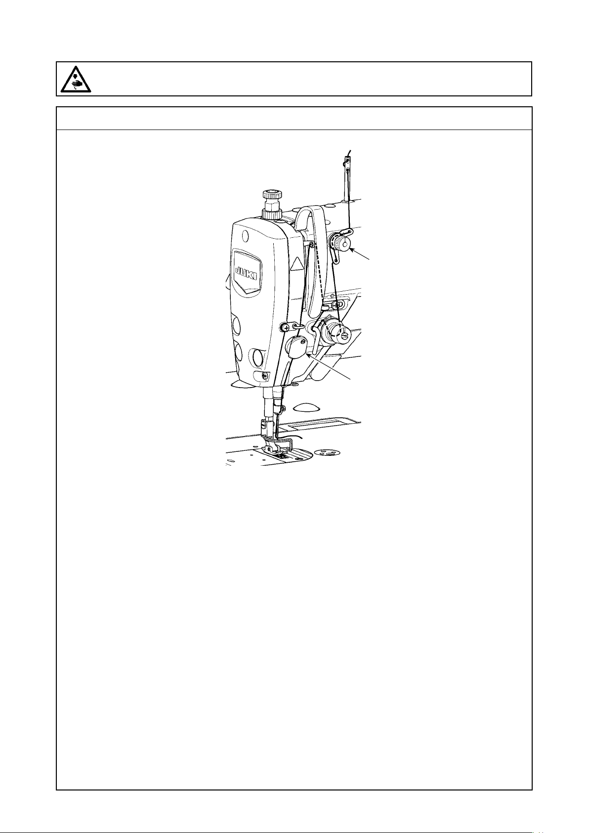
(8) Adjusting the needle thread presser device
WARNING :
Be sure to turn the power OFF before the following work in order to prevent personal injury due to
unintentional starting of the sewing machine.
Standard adjustment
1) Needle thread presser device
❷
❶
– 40 –
Page 57
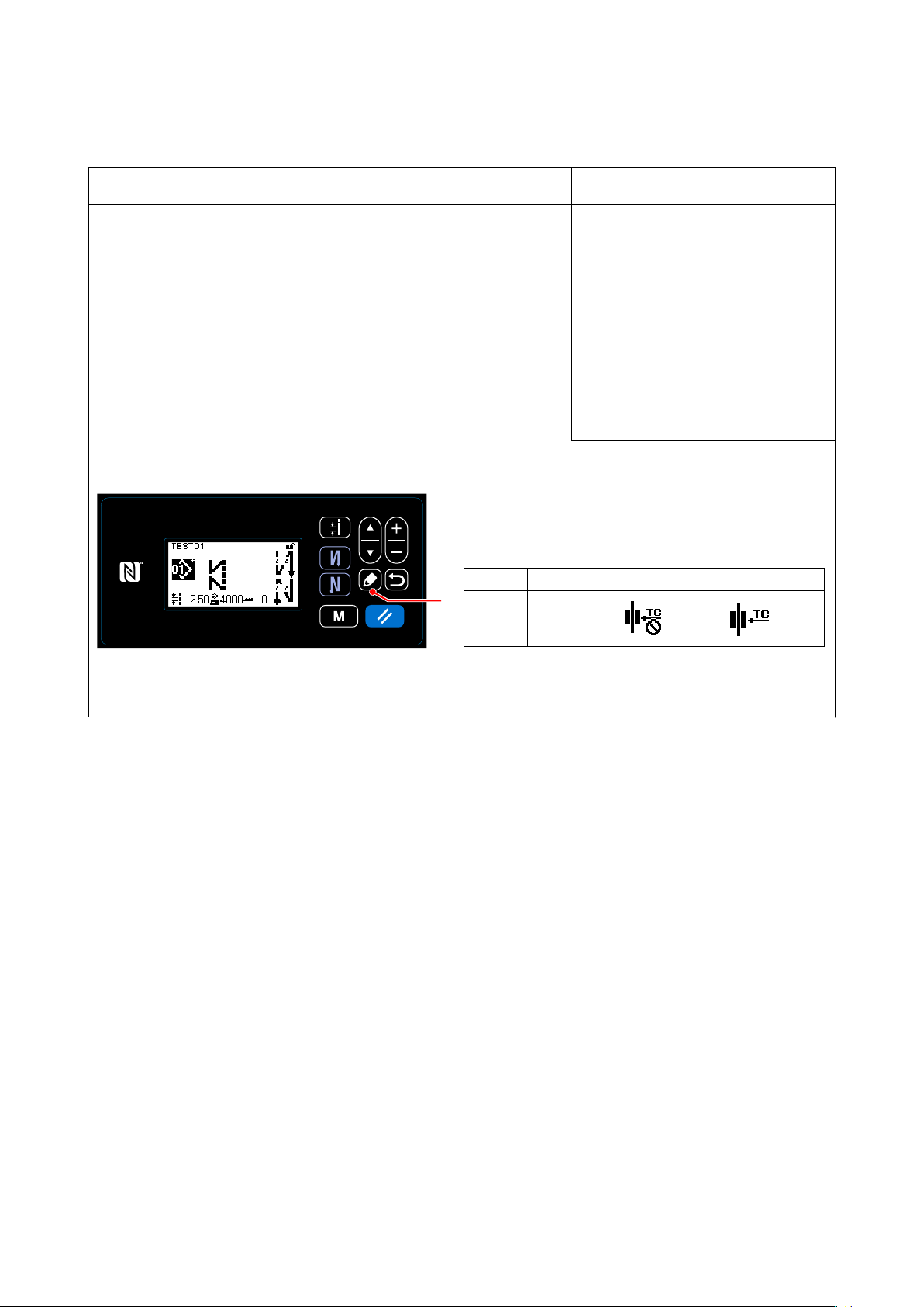
Adjustment Procedure
Results of Improper Adjustment
1) Adjusting the needle thread presser device
The needle thread presser device is able to tuck the needle thread
on the wrong side of material as in the case of the conventional wiper
device.
[Feature]
• By operating the needle thread presser device ❶ and reducing the
needle thread supply from the thread take-up, it is possible to lessen
so-called “bird’s nest phenomenon” of the cloth lining.
• Operability around the needle entry point is improved.
• Applicability of various kinds of attachments designed for use around
the needle entry point is improved.
1)-1. DDL-9000C-S
●How to set up the needle thread presser device
Press the ❺ button on the sewing screen at the time of
selection of free stitching, constant-dimension sewing,
and multi-layer stitching to display a sewing pattern
edit screen.
No.
❺
S042
Item Input range
Needle
thread
presser
◦ In the case the memory switch
"U056 Reverse-rotation needle-up
after thread trimming" is enabled,
the length of needle thread be-
comes longer. So, in this case,
the needle thread presser device
should be set to "OFF".
:OFF/ :ON
1)-2. DDL-9000C-F
●How to set up the needle thread presser device
– 41 –
Page 58
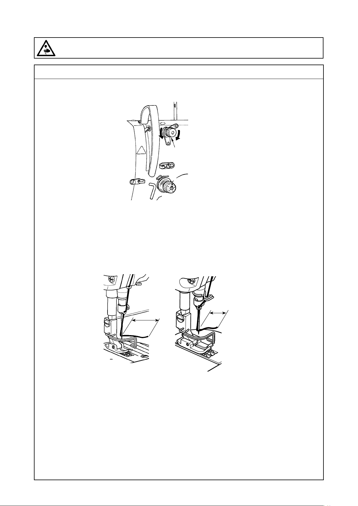
(8) Adjusting the needle thread presser device
WARNING :
Be sure to turn the power OFF before the following work in order to prevent personal injury due to
unintentional starting of the sewing machine.
Standard adjustment
2) Adjusting the remaining length of needle thread
B
A
❷
3) Length of needle thread remaining at the needle
[S type] [H type]
c
c = 35 to 45mm
c
– 42 –
Page 59
Adjustment Procedure
2) Adjusting the remaining length of needle thread]
Adjust the length of needle thread remaining at the needle to 35 to 45 mm (for both the S and H types) by
turning thread tension No. 1 nut ②.
1) Turn thread tension No. 1 nut ② clockwise (in direction A), to shorten the thread length remaining on the
needle after thread trimming or counterclockwise (in direction B), to lengthen the thread length.
3) Length of needle thread remaining at the needle
The needle thread length C dimensions of the S type and H type is 35 to 45mm.
* So-called "bird's nest phenomenon" is reduced by shortening the length of needle thread remain-
ing at the needle. In this case, however, the needle thread is likely to slip off the needle eyelet. To
reduce slip-off of the needle thread, sewing speed at the beginning of sewing should be reduced.
[Memory switch]
• U286 Sewing speed during thread presser operation : Reduce (Factory-adjusted to 300 sti/min at the time
of shipment)
• U293 Sewing speed resetting angle when the thread presser operates (340 degrees preset at the time
of factory shipment)
Enlarge the U286 speed range.
No. Item Setting range
Sewing speed during thread presser operation
U286
This memory switch is used for setting the speed to be employed when the thread presser operates.
Sewing speed resetting angle when the thread presser
U293
operates
This memory switch is used for setting the angle at which the
sewing speed employed when the thread presser operates is
reset.
* The setting is enabled when the thread presser operates.
100 to 3000 300 sti/min
0 to 720 340 Degree
Factory-
adjusted
Unit
– 43 –
Page 60
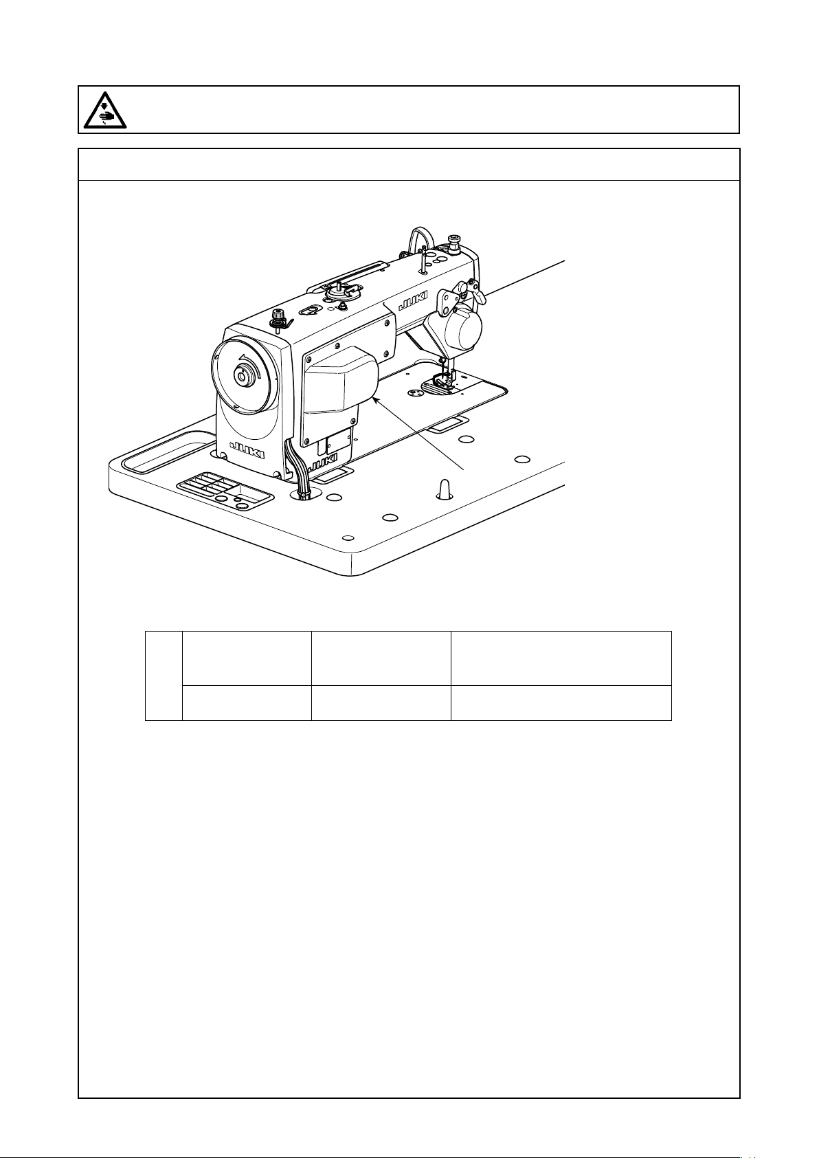
(8) Adjusting the needle thread presser device
WARNING :
Be sure to turn the power OFF before the following work in order to prevent personal injury due to
unintentional starting of the sewing machine.
Standard adjustment
4) Response to problems occurring at the beginning of sewing
Auto-lifter device (AK) ❹
DDL-9000C-S AK-154
❹
DDL-9000C-F Active presser device Standard
❹
It depends on specication
(An optional device is acceptable.)
– 44 –
Page 61
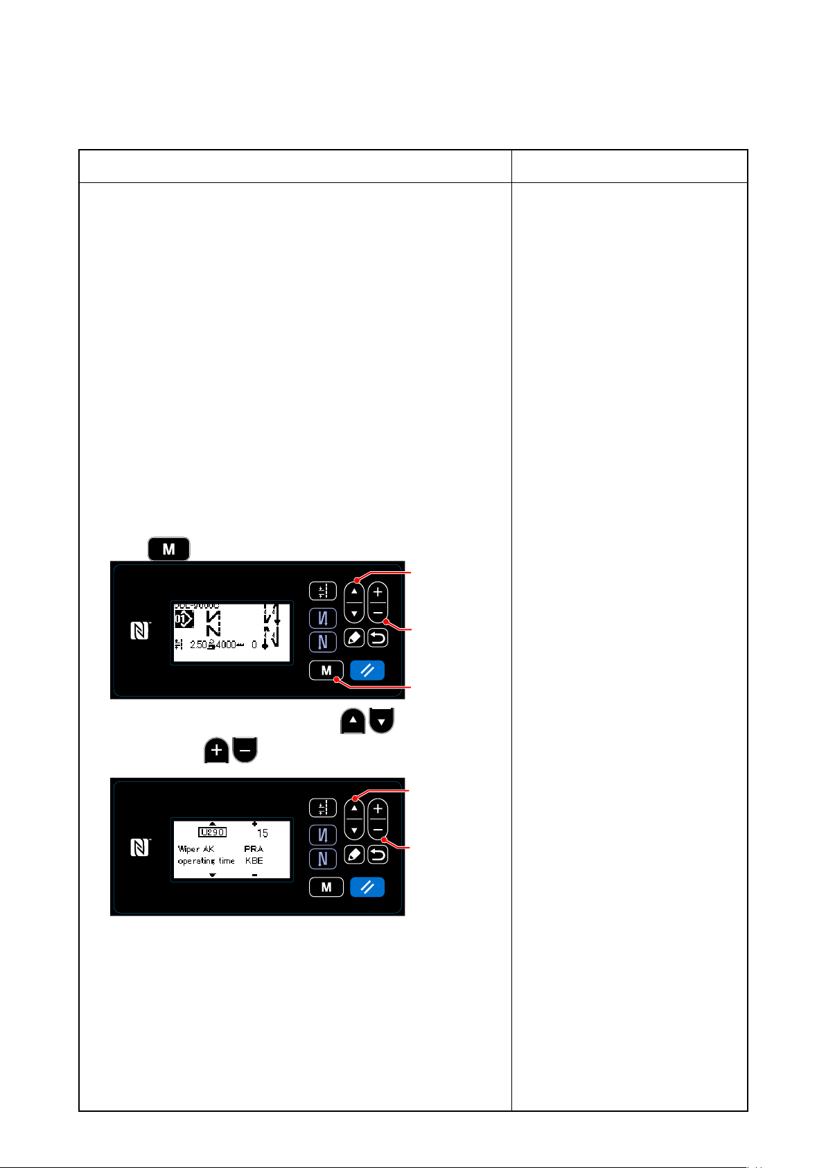
Adjustment Procedure
Results of Improper Adjustment
4) Response to problems occurring at the beginning of
sewing
• In the case needle thread breakage occurs when using a thin thread
or fragile thread
• In the case needle thread is not tucked on the wrong side of material
• In the case needle thread breakage occurs when starting sewing
from the material end (such as sewing the material with needle thread
tucked on the undersurface of material)
If any of the aforementioned problems occurs, the assist function which
works to reduce the presser foot pressure at the beginning of sewing
can be set by using the auto-lifter device ❹ (AK-154)
* The AK-154 ❹ can be optionally installed. (Part number: 40174617)
4)-1. DDL-9000C-S
When installing the auto-lifter device ❹ (AK), the function of auto-lifter
is actuated.
1) Turn ON the power switch.
2) Press ❾.
❶
❷
3) Move the cursor to ”U290” by pressing ❶. Input the lifting
time using with ❷.
❾
❶
❷
◦ The AK-154 device ❹ is exclusive
for the DDL-9000C-S.
◦ In the case the AK-154 ❹ is not
used, the presser foot pressure
should be reduced to allow the nee-
dle thread to be released smoothly.
(The recommended presser foot
pressure is 30 N (3 kg) or less.)
Adjust the presser foot pressure
and the sewing speed appropri-
ately to prevent insufcient feed
efciency due to jumping or other
faults of the presser foot. Conrm
the adjustment result by actually
sewing the material.
◦ If the adjustment value of the op-
erating time of the AK-154 ❹ is
increased while the presser foot
pressure is high, the operating
noise will become larger. Adjust the
adjustment value of the operating
time of the AK-154 and the pressure
foot pressure while visually check-
ing the needle thread.
Factory-set value : 20
Adjustable range : 0 to 50
The longer the lifting time is increased, the higher the presser foot
sole is brought up above the throat plate.
(Caution) The amount of uplift of the presser foot above the
throat plate varies according to the material thick-
ness of the item to be sewn and the presser foot
pressure. Be sure to check the actual condition
before starting sewing.
– 45 –
Page 62

(8) Adjusting the needle thread presser device
WARNING :
Be sure to turn the power OFF before the following work in order to prevent personal injury due to
unintentional starting of the sewing machine.
Standard adjustment
4) Response to problems occurring at the beginning of sewing
– 46 –
Page 63
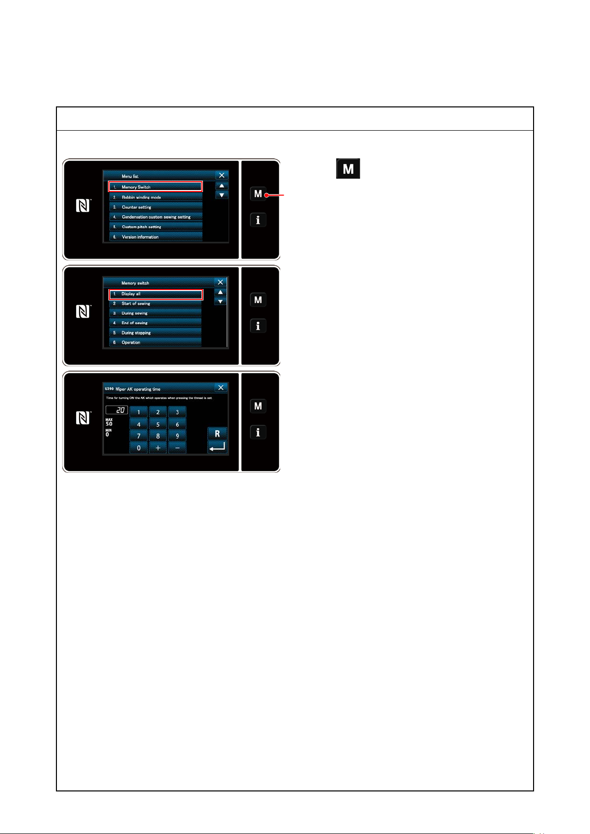
4)-1. DDL-9000C-S
Adjustment Procedure
1. Press ❶on the sewing screen to display the
mode screen.
❶
2. Select the "1. Memory switch".
The "memory switch type selection screen" is dis-
played. Select the "1. Display all".
2. Select the "U290 Wiper AK operating time".
Input the lifting time.
– 47 –
Page 64
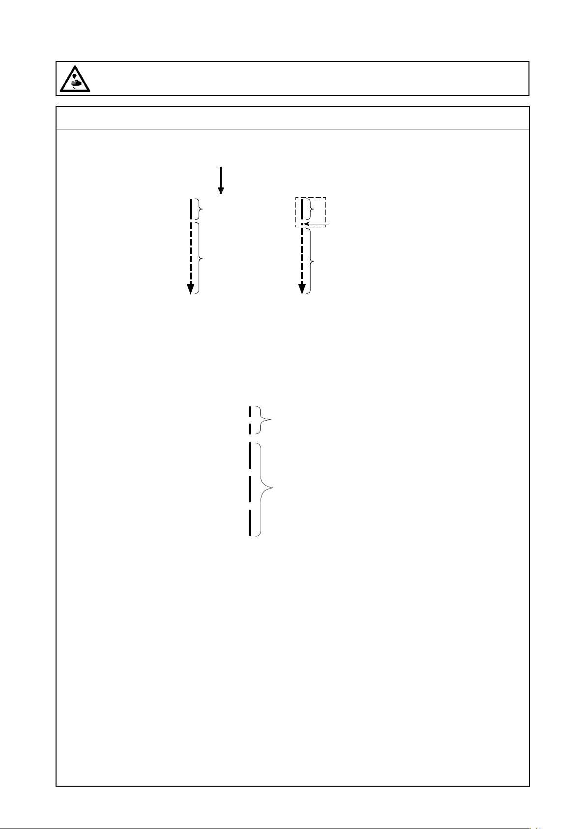
(8) Adjusting the needle thread presser device
WARNING :
Be sure to turn the power OFF before the following work in order to prevent personal injury due to
unintentional starting of the sewing machine.
Standard adjustment
5) Response to problems occurring at the beginning of sewing
Condensation
A
B
A>B A>B
A : Stitch pitch of the rst stitch
B : Normal stitch pitch
[How to adjust condensation pitch]
Custom condensation (CC)
A
Condensation
or
B
Sewing
pitch
Condensation
pitch
– 48 –
Page 65
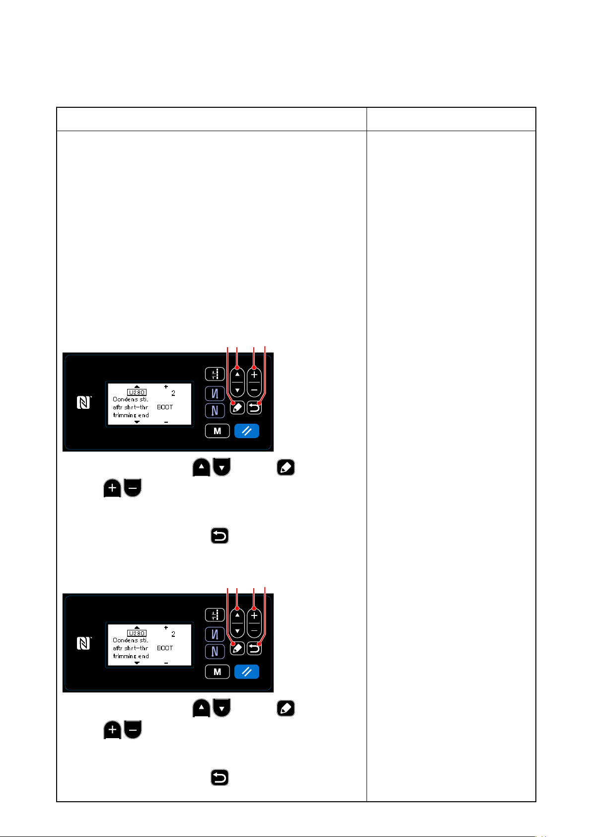
Adjustment Procedure
Results of Improper Adjustment
5) Response to problems occurring at the beginning of
sewing
(Caution) With respect to the memory switch settings, a sewing
speed of 250 sti/min is recommended for "U286 Sewing
speed during thread presser operation", and an angle
of 720 degrees is recommended for "U292 Soft-start
resetting angel when the thread presser operates".
In the case of carrying out shorter-thread remaining thread trimming
(when condensation is placed in ON), set values of the condensation
pitch and the number of stitches are adjustable. Adjust those set values
appropriately according to the item to be sewn.
5)-1. DDL-9000C-S
[Setting the number of condensation stitches]
❷❶❺ ❻
◦ So-called "bird's nest phenomenon"
is reduced by increasing the pitch
of the rst stitch at the beginning of
sewing.
1) Select "U280" by pressing ❶. Press ❺.
2) Press ❷ and enter the number of condensation stitches
at the end of sewing for shorter-thread remaining thread trimming.
(Factory-set value: 2)
3) Conrm your entry by pressing ❻. Then, the sewing screen is
displayed.
[Setting the condensation pitch]
❷❶❺ ❻
1) Select "U281" by pressing ❶. Press ❺.
2) Press ❷ and enter the condensation pitch at the end of
sewing for shorter-thread remaining thread trimming.
(Factory-set value: S type 0.3; H type 0.5)
3) Conrm your entry by pressing ❻. Then, the sewing screen is
displayed.
◦ If the condensation pitch is de-
creased, the phenomenon where
the needle enters the same needle
entry point will likely to occur, result-
ing in unstable formation of thread
loop at the time of thread trimming.
As a result, thread trimming fault is
likely to occur. It is therefore nec-
essary to adjust the condensation
pitch carefully. (The needle entry
phenomenon differs according to
the material to be sewn and the
needle count, the pitch should be
increased if thread trimming failure
occurs.)
– 49 –
Page 66
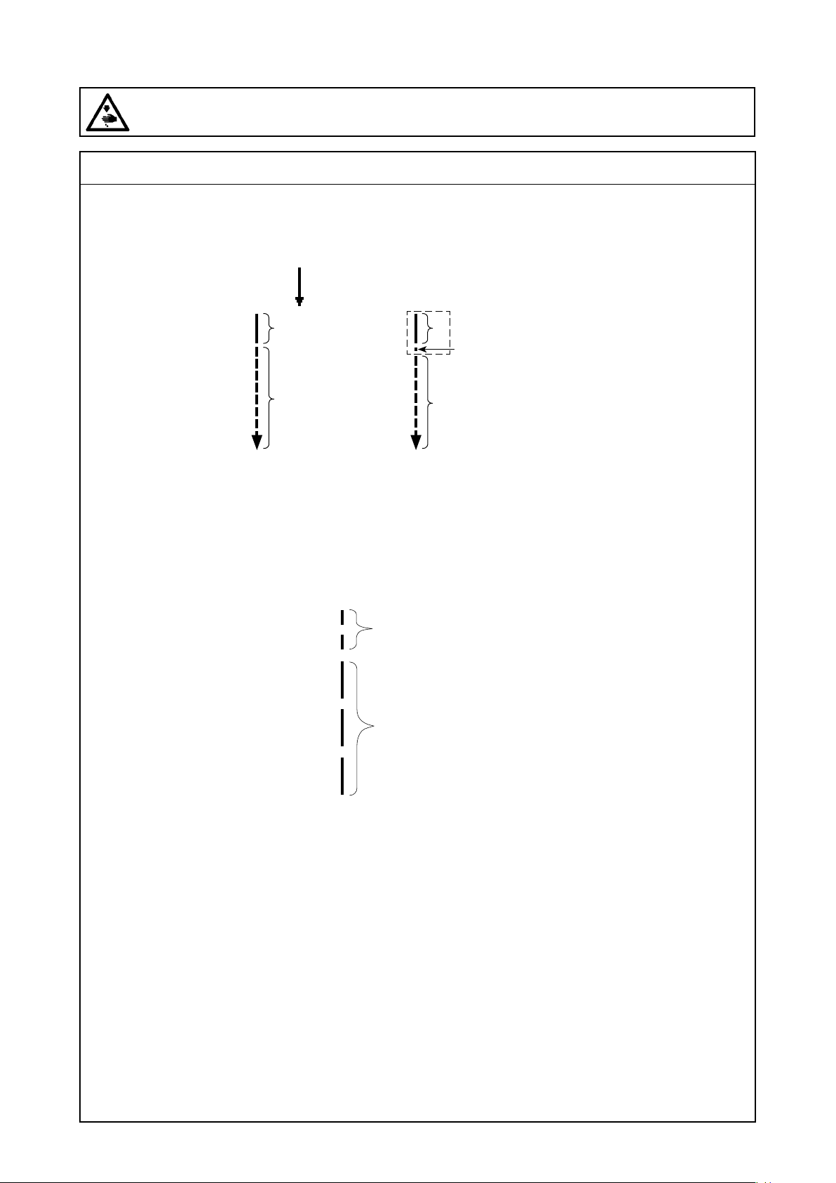
(8) Adjusting the needle thread presser device
WARNING :
Be sure to turn the power OFF before the following work in order to prevent personal injury due to
unintentional starting of the sewing machine.
Standard adjustment
5) Response to problems occurring at the beginning of sewing
Condensation
A
B
A>B A>B
A : Stitch pitch of the rst stitch
B : Normal stitch pitch
[How to adjust condensation pitch]
Custom condensation (CC)
A
Condensation
or
B
Sewing
pitch
Condensation
pitch
– 50 –
Page 67
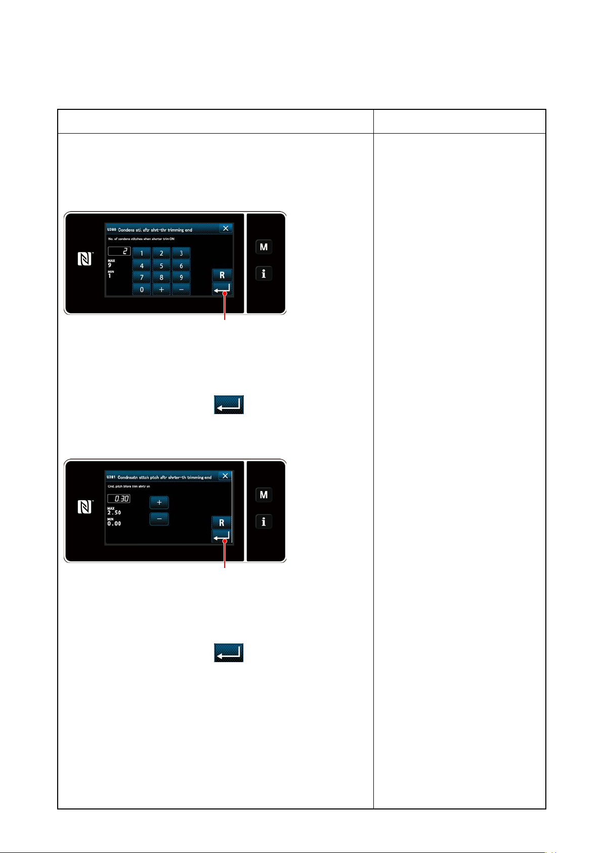
Adjustment Procedure
5) Response to problems occurring at the beginning of
sewing
5)-2. DDL-9000C-F
[Setting the number of condensation stitches]
❶
1. Select "U280 Number of end condensation stitches for shorter-
thread remaining thread trimming" from "1. Display all".
2. Set the number of stitches.
(Factory-set value: 2)
3. Conrm your entry by pressing ❶. Then, the sewing screen
is displayed.
Results of Improper Adjustment
[Setting the condensation pitch]
❶
1. Select "U281 End condensation pitch for shorter-thread remaining
thread trimming" from "1. Display all".
2. Set the number of stitches.
(Factory-set value 0.3; H type 0.5)
3. Conrm your entry by pressing ❶. Then, the sewing screen
is displayed.
◦ If the condensation pitch is de-
creased, the phenomenon where
the needle enters the same needle
entry point will likely to occur, result-
ing in unstable formation of thread
loop at the time of thread trimming.
As a result, thread trimming fault is
likely to occur. It is therefore nec-
essary to adjust the condensation
pitch carefully. (The needle entry
phenomenon differs according to
the material to be sewn and the
needle count, the pitch should be
increased if thread trimming failure
occurs.)
– 51 –
Page 68
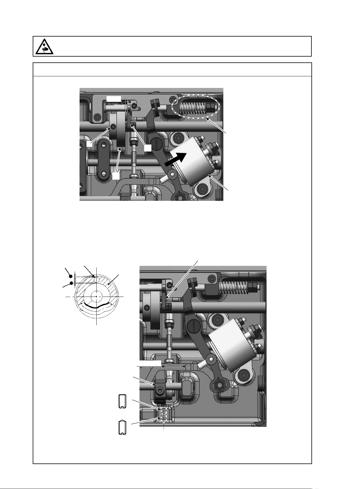
(9) Adjusting the thread trimming unit
WARNING :
Be sure to turn the power OFF before the following work in order to prevent personal injury due to
unintentional starting of the sewing machine.
Standard adjustment
1) Adjustment of the thread trimming cam position
2mm
❹
❷
❸
❺
❶
2) Adjustment of the thread trimming link stopper screw
❸
Outside
Inside
❾
The screw tip is at.
G
16.5mm
❽
❻
The screw tip is pointed.
❼
– 52 –
Page 69

Adjustment Procedure
1) Adjustment of the thread trimming cam position
1. Assume the condition such that the thread trimming solenoid ❶ is
attracted by hand.
2. Loosen and adjust the thread trimming cam setscrew ❹ so that
the gap length becomes 2mm between the thread trimming cam
❷ and the cam follower ❸.
3. After adjustment, tighten two thread trimming cam setscrews ❹.
(Caution) After adjustment, make conrmation according to
[3.-(9)-3) Standard timing for the thread trimming
cam].
4. Apply exclusive grease (JUKI grease A) to the stopper spring part
❺.
Results of Improper Adjustment
2) Adjustment of the thread trimming link stopper screw
1. Turn the hand wheel and adjust the thread trimming roller ❺ to the
inlet section of the thread trimming cam groove.
2. Loosen the thread trimming link stopper setscrew B ❼.
3. Move the thread trimming link stopper setscrew A ❻ and adjust the
clearance to be uniform between the thread trimming roller ❺ and
the thread trimming cam groove on both inside and outside.
4. Tighten the thread trimming link stopper setscrew B ❼.
In this case, make sure that the thread trimming link stopper set-
screw A ❻ does not move.
5. Try to move the cam follower ❸ to the right and left and conrm
that the thread trimming roller ❺ enters smoothly without touching
the thread trimming cam groove.
6. The thread trimming connecting rod bracket ❽ shall be positioned
16.5 mm away from a machining surface.
○ Be careful about the distance of
16.5 mm because it inuences the
thread trimming motion.
– 53 –
Page 70
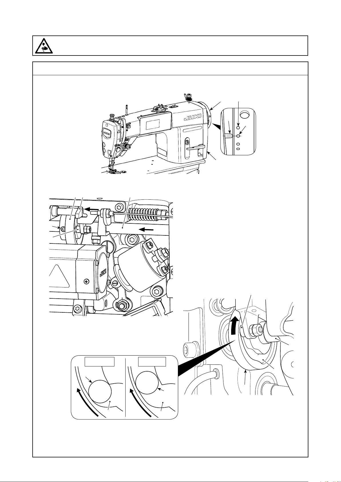
(9) Adjusting the thread trimming unit
WARNING :
Be sure to turn the power OFF before the following work in order to prevent personal injury due to
unintentional starting of the sewing machine.
Standard adjustment
3) Adjustment of the thread trimming cam position
❻
B′
❼
A
B
❺
❶ ❹❸
E
D
❷
Illustration as observed from D (right side face)
Correct (F) Wrong (G)
❷
C
C
❷
❹
C
❸
❷
Turn thread trimming cam ❸ in the direction
of arrow until the outer periphery of thread
trimming cam groove C comes in contact with
roller ❷ and stops. At this position, x thread
trimming cam setscrew ❼.
– 54 –
Page 71

Adjustment Procedure
3) Adjustment of the thread trimming cam position
1. For checking of the thread trimming cam timing
The purpose of the adjustment of the thread trimming cam is to align
marker line A on pulley cover ❺ with green marker dot B on handwheel ❻.
1. Tilt the sewing machine head. (In the case of H type model, use
white marker dot B´.)
2. Turn handwheel ❻ by hand in the normal direction of rotation until
the thread take-up lever goes up slightly below the upper dead
point. Press cam follower ❶ with ngers to the left (in direction of
arrow E) to t roller ❷ to in groove C in thread trimming cam ❸.
3. In this state, turn handwheel ❻ in the direction which is opposite to
the normal direction of rotation until handwheel ❻ will go no further.
(If the handwheel is turned further, it reaches the position at which
cam follower ❶ starts moving.)
At this time, marker line A on pulley cover ❺ aligns with green
marker dot B on handwheel ❻.
Results of Improper Adjustment
◦ In the case of using a high-count
lament thread, thread loop forma-
tion may be unstable. If faulty loop
spreading occurs in this state, cor-
rect the thread trimming cam timing
by aligning the marker line on the
pulley cover with the red marker
dot, instead of the green marker
dot, on the handwheel.
2. Adjustment of the thread trimming cam timing
1. Tilt the sewing machine head.
2. Loosen the screws No.1 and No. 2 of thread trimming cam setscrew
❼ in the written order.
3. Align marker line A on pulley cover ❺ with green marker dot B
on handwheel ❻. (In the case of H type model, use white marker
dot B´.)
4. Pressing cam follower ❶ to the left (in the direction of arrow E),
engage thread trimming cam ❸ with roller ❷. Then, turn only thread
trimming cam ❸ with ngers in the direction which is opposite to the
normal direction of rotation of feed driving shaft ❹ until it will go no
further without turning feed driving shaft ❹. At this position, tighten
the screws No. 1 and No. 2 of thread trimming cam setscrew ❼
in the written order while pressing thread trimming cam ❸ against
roller ❷.
◦ The alignment point between
thread trimming cam ❸ and roller
❷ is position (F) from which cam
follower ❶ starts moving. Position
(G) at which you feel that thread
trimming cam ❸ comes in contact
with roller ❷ for the rst time during
adjustment is not the correct align-
ment position.
* Be sure to correct the thread trim-
ming cam timing carefully since it
largely affects the loop spreading
timing.
– 55 –
Page 72
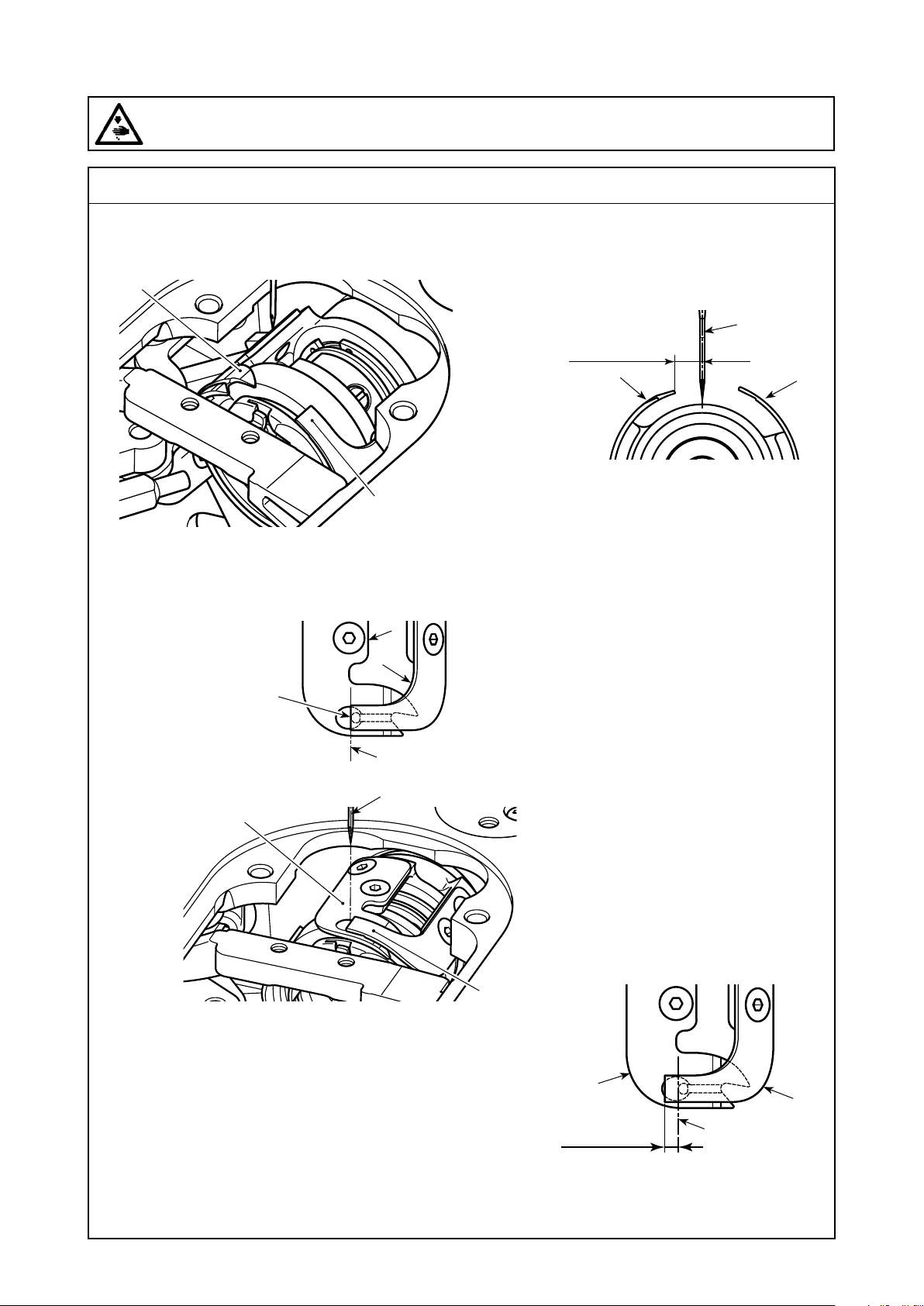
(9) Adjusting the thread trimming unit
WARNING :
Be sure to turn the power OFF before the following work in order to prevent personal injury due to
unintentional starting of the sewing machine.
Standard adjustment
4) Adjusting the knife unit
1. For checking the knife unit
❶
❷
The distance from center of
needle A to the tip of loop
spreading knife ❶
S type : 5.5 to 6.5 mm
H type : 5.0 to 6.0 mm
❶
A
❷
Standby state of the knife
Far end of the hole in
loop spreading knife
aligns with the tip of
❶
thread trimming knife ❷
❶
Fig.1
❶
❷
A
A
❷
Fig.2
Aligning state of salient portion of loop
spreading knife and thread trimming knife
– 56 –
❶
2.5 to 3mm
State of engagement of knife
A
Fig.3
❷
Page 73

Adjustment Procedure
4) Adjusting the knife unit
1. For checking the knife unit
1. Check to make sure that the power switch is in the OFF state.
Remove the gauge (presser foot, throat plate and feed dog) from
around the needle.
2. In the standby state of loop spreading knife ❶, the distance from
center of needle A to the tip of loop spreading knife ❶ is 5.5 to 6.5
mm. (H type: 5.0 to 6.0 mm)(Refer to Fig.1)
Results of Improper Adjustment
◦ Be aware that, if the distance be-
tween loop spreading knife ❶ and
center of needle A is reduced,
thread loop is likely to interfere with
loop spreading knife ❶.
* Refer to "3.-(9)-4)-2. Adjustment of
the knife unit" for how to adjust it.
3. The purpose of adjustment of the aligning position of loop spread-
ing knife ❶ and thread trimming knife ❷ (far end of the hole in
loop spreading knife ❶ and the tip of thread trimming knife ❷) is
to align the aforementioned aligning position with center of needle
A. (Refer to Fig.2)
4. The amount of engagement between loop spreading knife ❶ and
thread trimming knife ❷ is 2.5 to 3 mm as measured from center
of needle A. (Refer to Fig.3)
◦ Be aware that, if the aligning posi-
tion of the loop spreading knife and
the thread trimming knife does not
align with center of needle A, the
length of thread remaining on the
material after thread trimming will
be longer.
◦ Be aware that, if the amount of
engagement between them is insuf-
cient, faulty thread trimming can
occur.
Refer to "3.-(9)-4)-2. Adjustment of
the knife unit" for how to adjust it.
◦ The needle thread may be trimmed
excessively short in the case thread
such as lament thread which is
likely to cause unstable thread
loop formation is used or thread
trimming is carried out at a posi-
tion where there is no material. If
the aforementioned phenomenon
occurs, it should be corrected by
carrying out the below-stated pro-
cedure.
1. Make the thread take-up spring
stroke larger than the standard
value.
2. Make the pitch for thread trim-
ming during condensation stitch
larger than the standard pitch.
3. Turn OFF the condensation
stitch operation when carrying
out thread trimming at a position
where there is no material.
– 57 –
Page 74
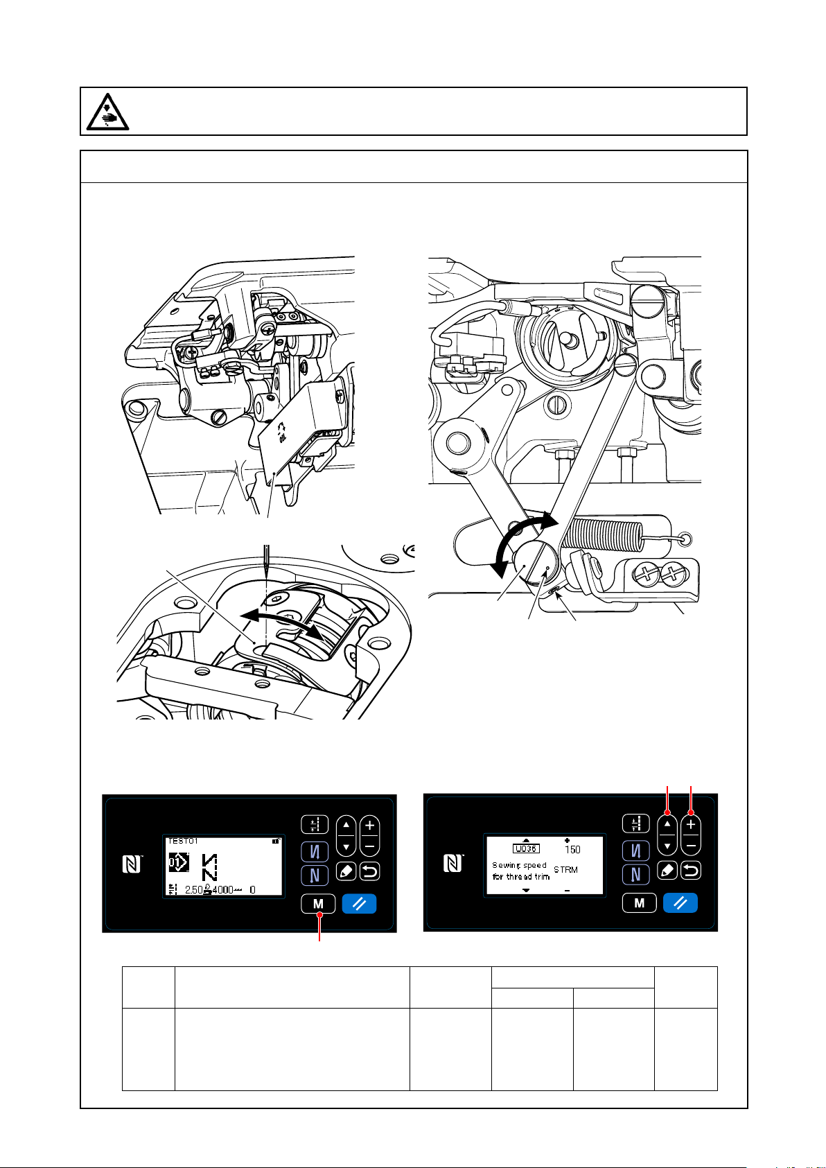
(9) Adjusting the thread trimming unit
WARNING :
Be sure to turn the power OFF before the following work in order to prevent personal injury due to
unintentional starting of the sewing machine.
Standard adjustment
4) Adjusting the knife unit
2. Adjustment of the knife unit
❺
❹
5)Adjustment of thread trimming speed
❻
❸A
❶ ❷
Memory switch
No.
❾
Item
U036 Speed during thread trimming
The maximum number of revolutions
during thread trimming differs with
the machine head.
Setting
150 to Max.
of thread
trimming
– 58 –
range
Initial value
S type H type
Unit
300 220 sti/min
Page 75
Adjustment Procedure
4) Adjusting the knife unit
2. Adjustment of the knife unit
1. Check to make sure that the power switch is in the OFF state.
Remove the gauge (presser foot, throat plate and feed dog) from
around the needle.
2. Tilt the sewing machine head.
3. Remove protective cover ❶.
4. Loosen loop spreading knife eccentric pin setscrews ❸ (two
pieces). Turn loop spreading knife eccentric pin ❷ with a at-blade
screwdriver to nely adjust the rotational-direction position of loop
spreading knife ❹.
5. After the adjustment, tighten loop spreading knife eccentric pin
setscrews ❸ (two pieces).
6. Attach protective cover ❶ back in place.
Results of Improper Adjustment
◦ Position of marker dot A on loop
spreading knife eccentric pin ❷
should be adjusted only from the
operator's side.
5)Adjustment of thread trimming speed
The thread trimming speed has been adjusted to 300 sti/min at the
time of shipment. This means that the high-speed thread trimming has
been selected. (In the case of H type model, thread trimming speed
has been factory set to 220 sti/min.)
Depending on the type of thread to be used, the thread trimming speed
should be increased. On the other hand, in the case of using fragile
thread (such as a high-count lament type thread or cotton thread),
the thread trimming speed should be decreased to reduce damage
to the thread.
Thread trimming speed should be adjusted when appropriate accord-
ing to the sewing process.
[How to adjust]
1) Press ❾.
2) Press ❶ to align the cursor on "U036". Input a thread
trimming speed with ❷.
– 59 –
Page 76
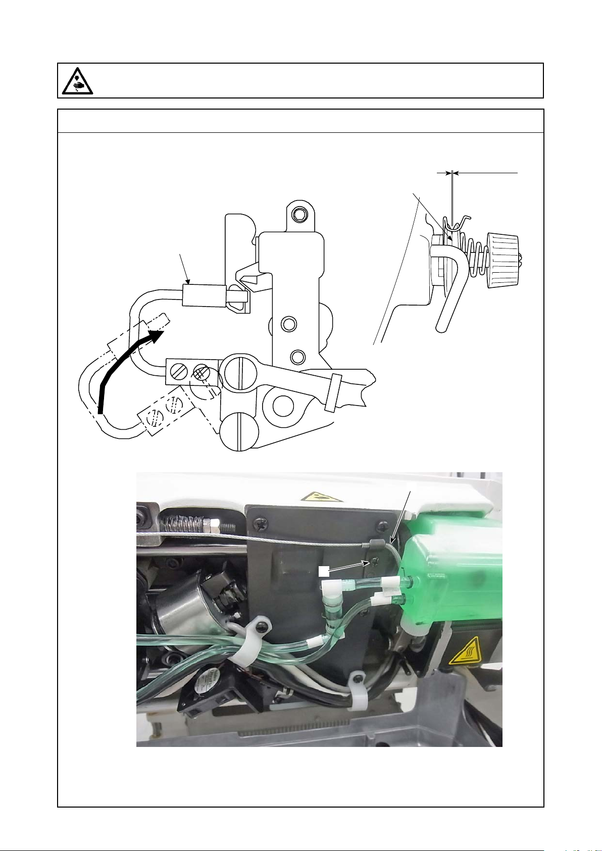
(9) Adjusting the thread trimming unit
WARNING :
Be sure to turn the power OFF before the following work in order to prevent personal injury due to
unintentional starting of the sewing machine.
Standard adjustment
6) Adjustment of rise of the second thread tension disc
❶
0.5 to 1mm
❹
❷
❸
– 60 –
Page 77

Adjustment Procedure
1. How to check the amount of rise of the second thread tension disc
(1) Set the thread take-up lever slightly in front of the upper
dead point.
(2) Raise the presser.
(3) The standard amount of the rise of the second thread ten-
sion disc ❹ is 0.5 to 1mm when the picker ❶ is pushed
toward the bobbin case side.
2. How to adjust the amount of rise of the second thread tension disc
<When increasing the amount of rise>
Loosen the thread tension release wire xing screw ❷ and move
the thread tension release wire ❸ to the right.
<When decreasing the amount of rise>
Loosen the thread tension release wire xing screw ❷ and move
the thread tension release wire ❸ to the left.
(Caution) After adjustments, tighten the thread tension release
wire xing screw ❷ assuredly.
Results of Improper Adjustment
◦ If the amount of rise of the second
thread tension disc ❹ is too small,
the needle thread length becomes
short at the time of thread trimming
and this can be a cause of thread
entanglement and needle thread
castoff errors at the beginning of
sewing.
– 61 –
Page 78
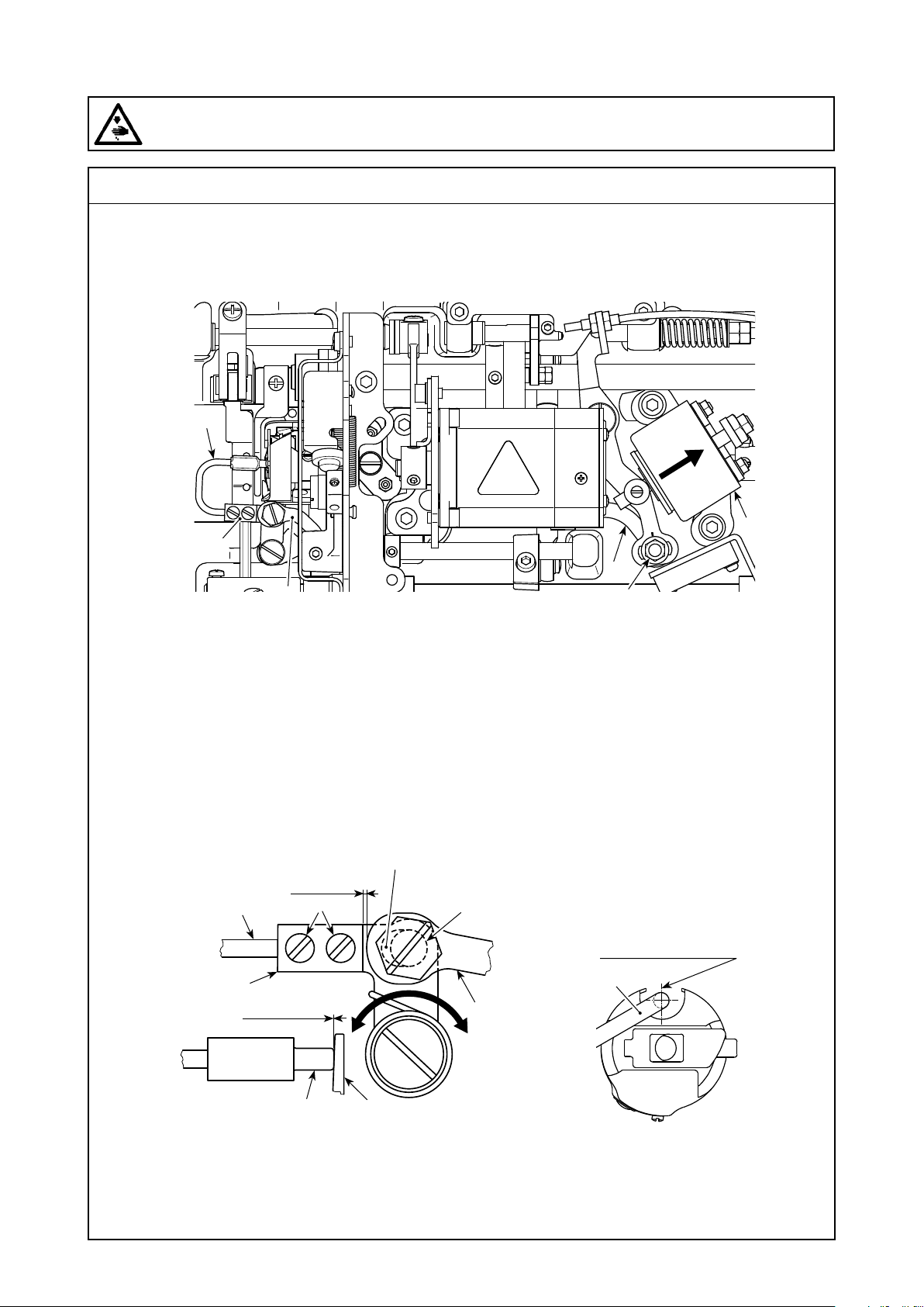
(9) Adjusting the thread trimming unit
WARNING :
Be sure to turn the power OFF before the following work in order to prevent personal injury due to
unintentional starting of the sewing machine.
Standard adjustment
7) Adjustment of the picker
❻
❹
❸
❶
❸
❷
Once the standard adjustment is carried out
correctly, there is a slot-shape space in picker
link ❸ to allow the picker to make a necessary
returning action (damper function).
(0.5 mm)
❻
❹
0 to 0.3 mm
❼
To be in contact
❸
❺❻
In the standard
adjustment state of
the picker, the center
of picker ❻ is almost
aligned with the
center of U-shape
section of bobbin
case.
❻
– 62 –
Page 79

Adjustment Procedure
The picker device is used in order to stabilize idling of the bobbin at
the time of thread trimming.
(Caution) When it is necessary to check how the picker ❻ is
adjusted, install the bobbin case and bobbin ❺ in the
hook rst, then check the picker.
1. Checking the standard adjustment
1. Check to make sure that the power switch is in the "OFF" state. Tilt
the sewing machine.
2. Bring thread trimming solenoid ❶ in the pull-in state by hand.
3. In this state, the standard adjustment value of the clearance between
picker link ❸ and picker arm ❹ is 0.5 mm. At this time, a clearance
of 0 to 0.3 mm is provided between bobbin ❺ and picker ❻.
2. Standard adjustment
1. Loosen picker link pin nut ❷ (9 mm). Carry out adjustment by mov-
ing picker link ❸ to the right and left.
2. After the adjustment, tighten picker link pin nut ❷.
3. Standard adjustment (Adjustment at the tip position)
1. Loosen picker setscrews ❼ (two pieces). Adjust the position of
picker ❻.
2. After the adjustment, tighten picker setscrews ❼ (two pieces).
Results of Improper Adjustment
◦ If there is no clearance between
bobbin ❺ and the tip of picker ❻,
picker ❻ strongly press bobbin
❺. As a result, the bobbin fails to
supply a required length of bob-
bin thread at the time of thread
trimming. In this case, the bobbin
thread is likely to be trimmed short
and thread slip-off at the beginning
of sewing is likely to occur.
◦ If there is an excessively large
clearance between bobbin ❺ and
the tip of picker ❻, thread required
for thread trimming may slip off the
tip of picker and the length of needle
thread remaining at the needle tip
after thread trimming will be short.
In addition, bobbin ❺ is likely to
idle frequently at the time of thread
trimming causing problems at the
beginning of sewing.
– 63 –
Page 80
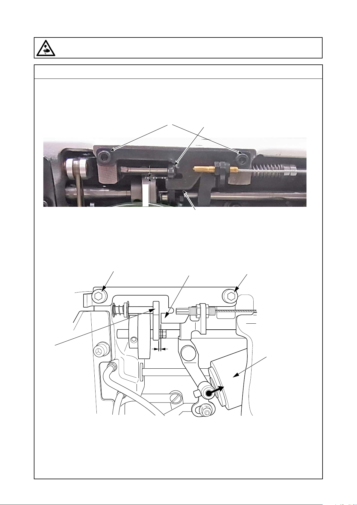
(9) Adjusting the thread trimming unit
WARNING :
Be sure to turn the power OFF before the following work in order to prevent personal injury due to
unintentional starting of the sewing machine.
Standard adjustment
8) Adjustment of the driven part stopper
❸
0.3mm
❸
❷
❶
❷
❸
❶
1mm
❹
– 64 –
Page 81

Adjustment Procedure
The driven part stopper ❷ is a safety device so that interference is
prevented between the needle and the moving knife even though
the roller comes off the thread trimming cam when any unexpected
problem (such as a service interruption) occurs.
1. In the state that the thread trimming device is not in action, adjust
two driven part stopper setscrews ❸ so that the gap length becomes 0.3mm between the notch ❶ of the camʼs driven part and
the camʼs driven part stopper ❷.
2. Adjust two driven part stopper setscrews ❸ so that the gap length
becomes 1mm between the notch ❶ of the camʼs driven part and
the camʼs driven part stopper ❷ when the thread trimming solenoid
❹ is moved in the direction of the arrow.
Results of Improper Adjustment
– 65 –
Page 82
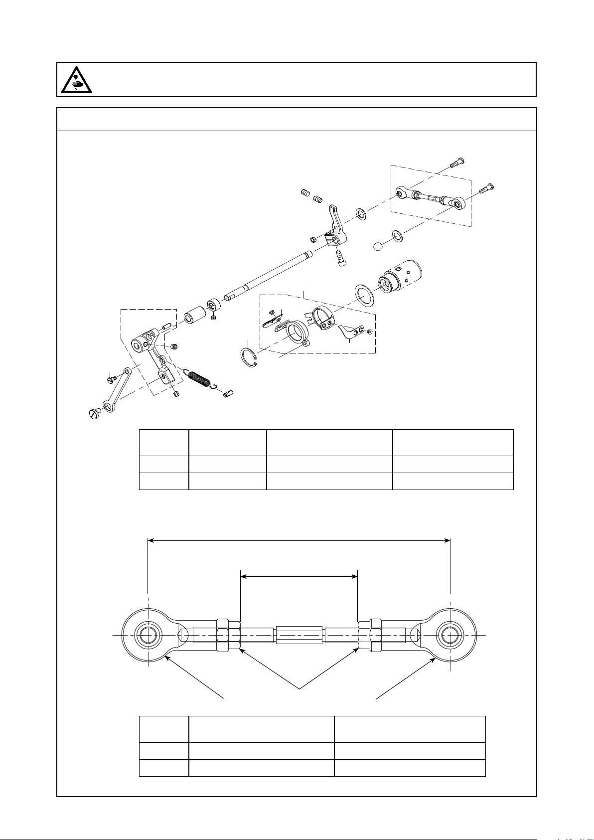
(9) Adjusting the thread trimming unit
WARNING :
Be sure to turn the power OFF before the following work in order to prevent personal injury due to
unintentional starting of the sewing machine.
Standard adjustment
9) Adjustment of the driven part stopper
❷
❺
❹
Ⓐ
Ⓐ
❶
❸
Knife unit ❶
Part No.
S type 40172485 40172487 40172486
H type 40174319 40172487 40172486
Handling device knife ❷
Part No.
Thread trimmer knife ❸
10) Installed length of the thread trimmer connector bar (asm.)
H type:101.5±0.2mm(S type:99.7±0.2mm
H type:Reference value = 39.5mm)
(
S type:Reference value = 37.7mm
(
❽
Connecting rod (asm.) R
Part No.
S type 40174398 99.7±0.2mm
❼
Connecting rod (asm.) R
)
)
❽
dimension
Part No.
H type 40174323
101.5±0.2mm
– 66 –
Page 83

Adjustment Procedure
9) Adjustment of the driven part stopper
[Method of replacement]
1. Let the sewing machine fall down.
2. Remove the needle, hook, and the inner hook presser.
3. Remove the moving knife link stepped screw ❹.
* Apply the LOCKTITE 243 on a screw at the time of recombination.
4. Remove the C ring ❺.
5. Remove the female unit ❶ from the metal.
Results of Improper Adjustment
10) Installed length of the thread trimmer connector
bar (asm.)
1. Install two rod ends ❽ so that they cross each other at right angles.
Then, x then with the nuts ❼.
2. In order to avoid loosening by mistake at the time of shipment,
“white paint” is applied to the nuts ❼.
3. Loosen the nuts ❼ when removing the thread trimmer connector
bar (asm.) (40086708) without drawing out the lower shaft. When
the nuts are loosened, the respective subsidiary parts are disas-
sembled and the thread trimmer connector bar can be taken out.
4. After disassembly, reassemble the parts so that the standard adjust-
ing values can be secured.
◦ If the two rod ends ❻ are not
crossed at right angles, the ob-
tained torque is the value for thread
trimming.
◦ If the center-to-center distance
(99.5±0.4mm) deviates from the
standard value, the initial position
of the moving knife is changed and
this can be a cause of thread trim-
ming failure.
– 67 –
Page 84
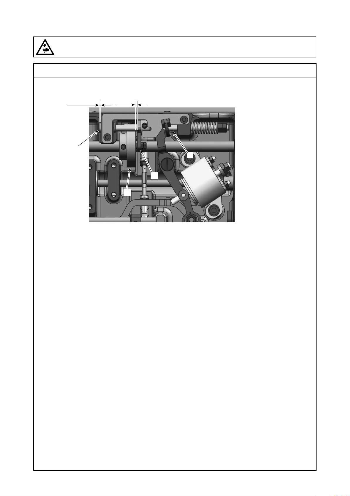
(9) Adjusting the thread trimming unit
WARNING :
Be sure to turn the power OFF before the following work in order to prevent personal injury due to
unintentional starting of the sewing machine.
Standard adjustment
11) Protrusion of the thread trimming shaft and stopper position
1 to 2mm
2mm
❾
❼
❸
– 68 –
Page 85

Adjustment Procedure
11)Protrusion of the thread trimming shaft and stop-
per position
1. When the thread trimmer solenoid is pulled, the amount of protru-
sion is 1mm to 2mm between the tip ❾ of the thread trimming shaft
and the end plane of the bed.
(Caution) Conrm that a clearance is secured between the cam
follower piece ❼ and the end plane of the thread
trimming cam ❸ to 2mm. (Refer to 3.-(9)-1).)
Results of Improper Adjustment
◦ If the amount of protrusion is too
small, the action sound of the
thread trimmer becomes large.
◦ If the amount of protrusion is too
large, the amount of picker action
becomes small and the lost motion
of bobbin may occur.
(If the amount of protrusion is too
excessive, short cutting of the
needle thread may arise. This is
because the needle thread is dis-
engaged from the picker.)
– 69 –
Page 86
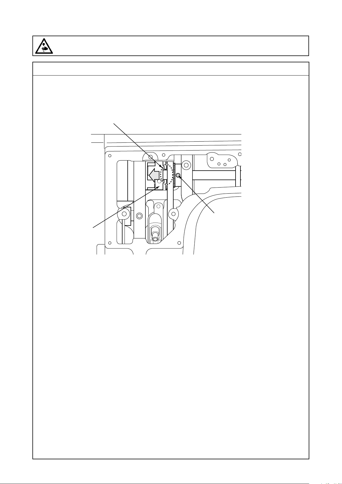
(10) Adjustment of thrust values of an upper shaft
WARNING :
Be sure to turn the power OFF before the following work in order to prevent personal injury due to
unintentional starting of the sewing machine.
Standard adjustment
A
B
❷
❶
– 70 –
Page 87

Adjustment Procedure
1. After everything has been installed for the upper shaft, remove
rattles from bearings (pressurizing).
(1) Assemble all parts for the upper shaft.
(2) Loosen two setscrews ❶ of the upper sprocket.
(3) Enter the tip of a tapered minus screwdriver into the coupling ❹
slot until it stops. (Part A)
* If the screwdriver tip is not inserted fully in the slot, the ange
part of the upper sprocket is deformed or destroyed.
(4) Lightly turn the screwdriver to move the coupling ❹ toward B in
the direction of the arrow.
* The torque to turn the screwdriver is 7kgf•cm. (Light turning is
sufcient.) If it is turned too strong, the ange part of the upper
sprocket is deformed or destroyed.
(5) Tighten the setscrew ❶ of the upper sprocket.
(6) Turn the upper shaft by 90 degress In regard to the second
screw, follow the same procedures as (3) to (5) above.
Results of Improper Adjustment
– 71 –
Page 88
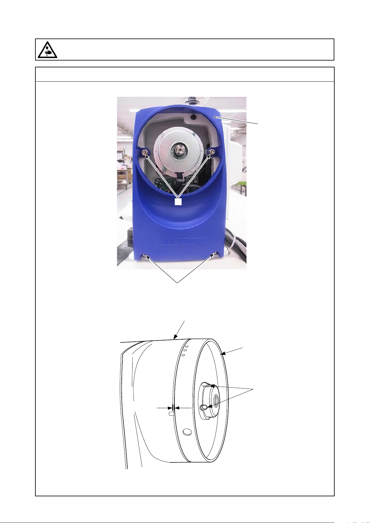
1mm
(11) Adjustment of external parts
WARNING :
Be sure to turn the power OFF before the following work in order to prevent personal injury due to
unintentional starting of the sewing machine.
Standard adjustment
1) Adjustment of the pulley cover
❸
❷
2) Clearance of the hand wheel
❷
❸
❶
❹
– 72 –
Page 89

Adjustment Procedure
1) Adjustment of the pulley cover
[Method of replacement]
1. Remove the hand wheel ❶.
2. Remove four pulley cover setscrews ❷.
(Cautions)1. At the time of re-assembly, the pulley cover ❸
should be kept raised.
2. At the time of re-assembly, handle the pulley
cover ❸ carefully not to pinch cables and others.
Results of Improper Adjustment
2) Clearance of the hand wheel
1. The clearance is 1mm between the hand wheel ❶ and the pulley
cover ❸.
For adjustments, loosen the hand wheel setscrews ❹ (2 pcs.)
◦ If a clearance is too much, this can
be a possible cause of entangle-
ment of the thread from the thread
stand.
– 73 –
Page 90
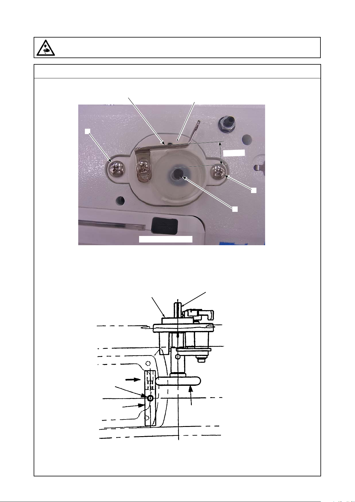
Adjustment of external parts
(11)
WARNING :
Be sure to turn the power OFF before the following work in order to prevent personal injury due to
unintentional starting of the sewing machine.
Standard adjustment
3) Adjustment of the bobbin winder unit
❻
❶
❷
14
mm
❶
❼
Operator side
In the state of OFF, the standard distance of the bobbin winder
lever ❻ is 14mm from the bobbin winder shaft ❼.
❷
❼
❺
❹
❸
– 74 –
Page 91
Adjustment Procedure
In regard to adjustments of the bobbin winder amount and winder
imbalance, refer to the relevant instruction manual.
In this manual, descriptions are provided in regard to problems of
winder shaft revolution errors.
1. Replacement of the bobbin friction wheel
(1) Remove two bobbin winder unit setscrews ❶.
(2) Take out the bobbin winder unit ❷.
(3) Conrm if there is extreme wearing out in the rubber section of the
bobbin winder friction wheel ❸.
If the amount of wearing out seems to be too much, replace the
worn-out section with a new one.
Bobbin winder friction wheel ❸
Part No. 26261503
2. Adjustment of the bobbin winder driver wheel position
(1) Remove the window plate (including the AK unit) from the rear
side of the arm.
(2) Loosen the bobbin winder driver wheel setscrews ❺ (2 pcs.) of
the bobbin winder driver wheel ❹.
(3) Mount the bobbin winder unit ❷ on the arm.
(4) Turn ON the bobbin winder lever ❻ and let the head ❶ coincide
with the bobbin winder lever ❻.
At that time, the head ❶ of the bobbin winder unit setscrew shall
be made to coincide with the bobbin winder lever ❻.
(5) Lightly make the bobbin winder driver wheel ❹ lightly contact with
the bobbin winder friction wheel ❸ and tighten two bobbin winder
driver wheel setscrews ❺.
(Cautions) 1. When the bobbin winder lever ❻ is turned OFF,
turn the hand wheel by hand and conrm that the
bobbin winder shaft ❼ does not turn.
2. Never apply grease or such an oily component to
the rubber section of the bobbin winder friction
wheel ❸. Otherwise, this can be a cause of fric-
tion.
Results of Improper Adjustment
◦ If the hand wheel is turned in the
state of OFF, this can be a cause
of abnormal abrasion.
– 75 –
Page 92
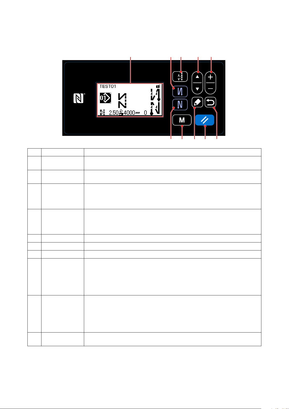
4.Control panel
(1) Names and functions of the panel keys
1) DDL-9000C-S
Switch/display Description
Item selection key This key is used for changing over the screen display or for displaying the edit screen.
❶
Refer to the explanation of each screen for details.
Data change key This key is used for changing the currently-displayed pattern number or for changing the
❷
numeric value shown on the counter. Refer to the explanation of each screen for details.
Reverse feed
❸
stitching (at start)
key
Reverse feed
❹
stitching (at end)
key
Edit key This key is used for displaying the edit screen, item section screen or details screen.
❺
Return key This key is used for returning the screen to the previous one.
❻
Pitch key This key is used for displaying the pitch entry screen.
❼
Reset key This key is used for resetting the error, for resetting the counter and for initial setting of
❽
Mode key This key is used for displaying the mode screen.
❾
Liquid crystal dis-
play section
This key is used for selecting whether or not the reverse feed stitching is performed at the
beginning of sewing.
The reverse feed stitching (at start) edit screen is displayed by keeping this key held
pressed for one second.
This key is used for selecting whether or not the reverse feed stitching is performed at the
end of sewing.
The reverse feed stitching (at end) edit screen is displayed by keeping this key held
pressed for one second.
the feed.
The operation panel is placed in the simple-lock state by keeping this key held pressed
for one second. The panel is released from the lock state by operating this key in the
same manner again.
Refer to "8-7-1. Simple lock" in instruction manual.
・The user level is displayed by operating this key in the normal manner.
・The serviceperson level 1 is displayed by keeping the key held pressed for three sec-
onds.
・The serviceperson level 2 is displayed by keeping the key held pressed for six sec-
onds.
Each screen is displayed on this LCD.
* Conrmation of data
Change in the pattern number is conrmed at the moment Data change key ❷ is pressed.
For the setting items of the memory switch and pattern number, the setting is changed by pressing Data
change key ❷ and conrmed by pressing Return key ❻.
The new setting of data of a setting item is also conrmed by selecting other setting item with Item selection
key ❶ after making a change.
❶ ❷❼
❻❹❸❾ ❽❺
– 76 –
Page 93
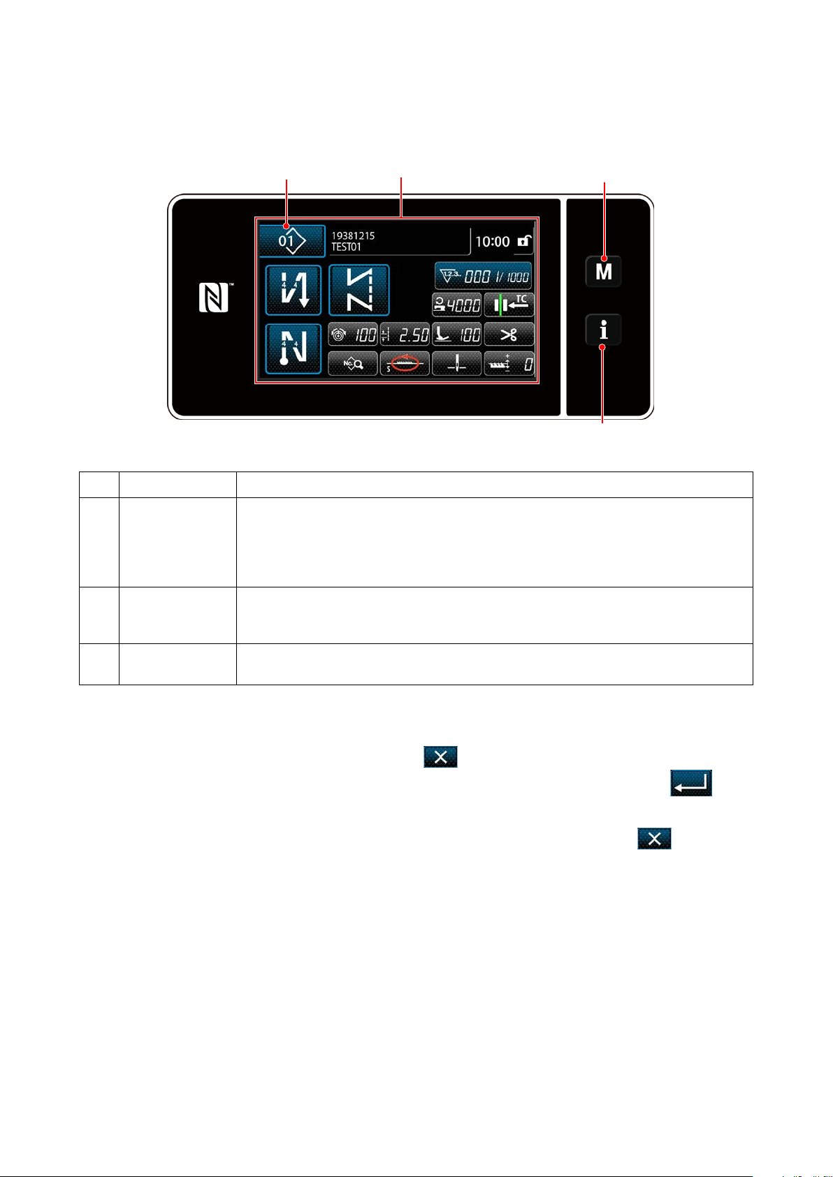
2) DDL-9000C-F
❹
Switch/display Description
Mode key This switch is used for displaying the menu screen.
❶
・The user level is displayed by operating this key in the normal manner.
・The serviceperson level 1 is displayed by keeping the key held pressed for three sec-
onds.
・The serviceperson level 2 is displayed by keeping the key held pressed for six seconds.
Information key This switch is used for displaying the information screen.
❷
・The user level is displayed by operating this key in the normal manner.
・The serviceperson level is displayed by keeping the key held pressed for three seconds.
Touch panel
❸
section
Each screen will be displayed. Press the key in the screen to operate the panel.
❸
❶
❷
* Conrmation of data
To change the pattern number, press Sewing pattern No. button ❹.
Select the sewing pattern you want to use. Then, press to conrm your choice.
For the setting items of the Memory switch or sewing pattern, change the target data and press to
conrm the change.
After the setting data on the number of stitches of reverse-feed stitching or the number of stitches of
multi-layer stitching has been changed, the changed setting data is conrmed by pressing .
– 77 –
Page 94
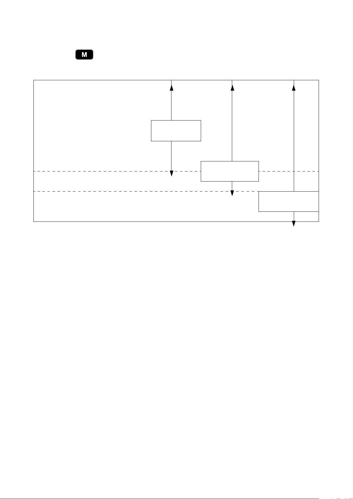
(2) To use the functions of the serviceperson level
1) DDL-9000C-S
By pressing ❾ button on the sewing screen for three seconds to display a mode screen for the
servisperson level 1 or for six seconds to display a mode screen for the servisperson level 2 respectively.
The function that can be used differs depending on the levels as follows.
01 Memory switch
02 Counter setting
03 Maintenance
04 Cycle pattern management
05 Custom pitch management
06 Condensation custom management
07 Ver. display
08 Contrast setting
09 Communication
10 USB format
11 Check program
It can be used
at the operator
level.
It can be used at the
serviceperson level 1.
12 Optional input/output settings
13 Data initialization
14 Function restrict setting
It can be used at the
serviceperson level 2.
– 78 –
Page 95
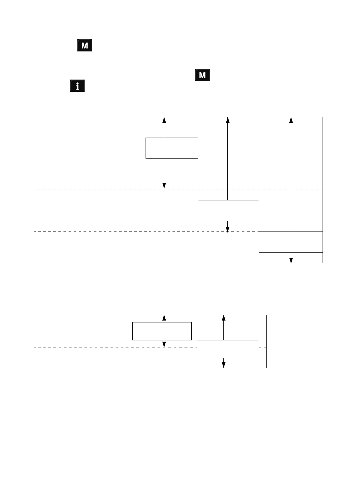
2) DDL-9000C-F
By pressing ❶on the sewing screen for three seconds to display a mode screen for the ser-
visperson level 1 or for six seconds to display a mode screen for the servisperson level 2 respective-
ly.
On the sewing screen for the switched level, press the ❶ again to display the mode screen and
press the ❷ to display the information screen respectively.
The function that can be used differs depending on the levels as follows.
【Mode screen】
01 Memory switch
02 Bobbin winding mode
03 Counter setting
04
Condensation custom management
05 Custom pitch management
06 Ver. display
07 Time setting
08 Check program
09 Panel setting
10 Key customize setting
11 At-hand switch setting
12 Optional input/output settings
13 Data initialization
14 Function restrict setting
【Information screen】
It can be used at
the operator level.
It can be used at the
serviceperson
level 1.
It can be used at the
serviceperson
level 2.
01 Data communication
02 Production control
03 USB formatting
It can be used at the
operator level.
It can be used at the
serviceperson level.
– 79 –
Page 96
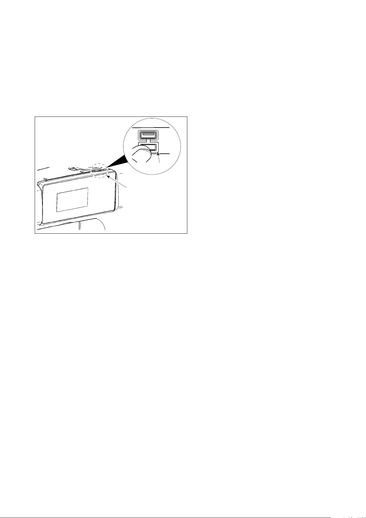
(3) External interface
1)USB
Sewing data, custom pitch data and condensation custom data can be copied on a commercially-available
USB thumb drive.
Refer to "4-4. Communication function" for details of how to copy the sewing data on a USB thumb drive.
① Position of the USB connector
1. USB thumb drive insertion position
The USB connector is provided on top ❶ of
the operation panel.
To use a USB thumb drive, remove connector
cover ❷ and insert the USB thumb drive into
❷
❶
the USB connector.
* In the case a USB thumb drive is not used,
the USB connector should be protected with
connector cover ❷ without exceptions.
If dust or the like enters the USB connector, a
failure can be caused.
② Precautions to be taken when handling USB devices
• Do not connect to the USB connection terminal other than the USB memory.
It may cause failure.
• Do not leave the USB device or USB cable connected to the USB port while the sewing machine is
in operation. The machine vibration can damage the port section resulting in loss of data stored on the
USB device or breakage of the USB device or sewing machine.
• Do not insert/remove a USB device during reading a program or sewing data.
It may cause data breakage or malfunction.
• Never forcefully insert a USB thumb drive into the USB connector while carefully checking the orientation of the USB thumb drive. Forceful insertion of the USB thumb drive can cause failure.
• JUKI does not compensate for loss of data stored on the USB device caused by using it with this sewing
machine.
• In principle, connect only one USB thumb drive to the operation panel. When two or more devices/
media are connected/inserted, the machine will only recognize one of them. Refer to the USB specications.
• Do not turn the power OFF while the data on the USB ash drive is being accessed.
③ USB specications
• Conform to USB 1.1 standard
• Applicable devices *
• Format supported ������ FAT 12, FAT 16, FAT 32
• Applicable medium size �� 4.1MB ~ (2TB)
• Consumption current ���� The rated consumption current of the applicable USB devices is 500 mA at
*1: JUKI does not guarantee operation of all applicable devices. Some device may not operate due to a
compatibility problem.
1 ����
USB memory
the maximum.
– 80 –
Page 97
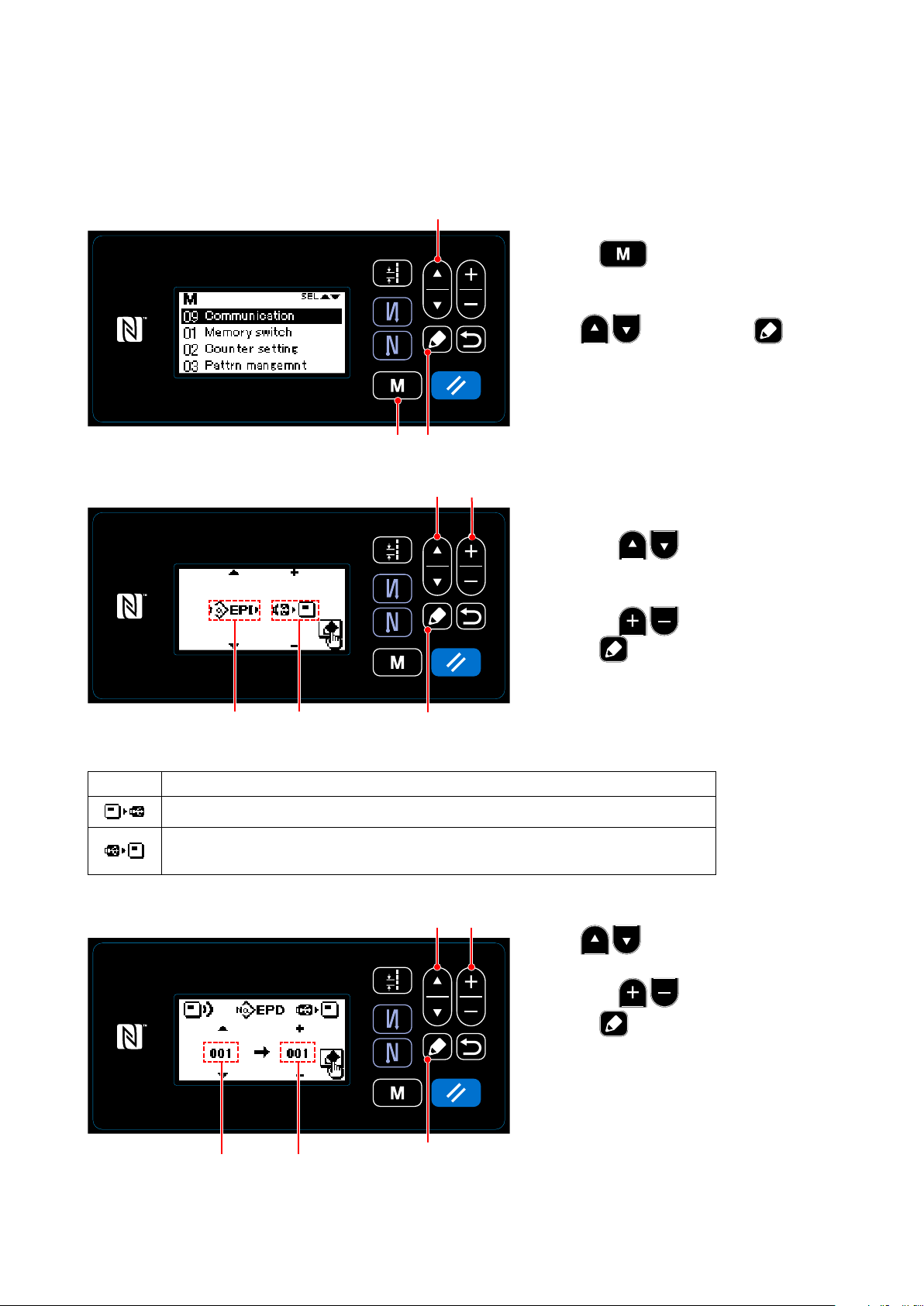
(4) Communication function
Data can be input/output by means of a USB thumb drive.
1) How to use the communication function (DDL-9000C-S)
① Selecting the communication function
❶
1. Press ❾on the sewing screen to
display the mode screen.
2. Select "09 Communication" by press-
ing ❶. Then, press ❺ to
display the communication data/direction
selection screen.
❾
❺
② Selecting the communication data and communication direction
A
Display
Data stored on the operation panel is written to the USB thumb drive.
Data stored on the USB thumb drive is written to the operation panel.
(If you have selected a program data, you can select only this direction.)
③ Selecting the target data number
B
Communication direction
❶
❺
❶ ❷
❷
1. Select the communication data A by
pressing ❶. (Refer to "4.(4)-3
List of communication data formats".)
2. Select the communication data B by
pressing ❷.
3. Press ❺ Data stored on the USB
thumb drive is written to the operation
panel.
1. Select the source data No. C by press-
ing ❶.
2. Select the destination data number D by
pressing ❷.
3. Press ❺to display the during-com-
munication screen and write the data.
After the completion of writing, the cur-
rent screen returns to the communica-
tion data number selection screen.
C
D
❺
– 81 –
* If the "POWER OFF" screen prompt is
displayed after the completion of writing,
turn the power OFF.
Page 98
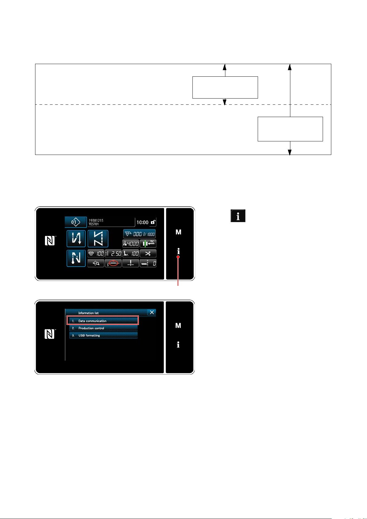
2) How to use the communication function (DDL-9000F-F)
It is possible to enter the input and output of data using a USB memory.
Depending on the level on the information screen, transmitted and received data differs as follows.
01 EPD Data transmission / reception
02 CC Data transmission / reception
03 CP Data transmission / reception
04 Memory switch data transmission / reception
05 All sewing machine data transmission / reception
06 PANEL program rewriting
07 SC soft rewriting
① Display the data communication list screen.
It can be used at the
operator level.
It can be used at the
serviceperson level 1.
1. Press ❶on sewing screen.
The "information screen" is displayed.
❶
2. Select "1. Data communication" on the
"information screen".
The "data communication list screen" is
displayed.
– 82 –
Page 99
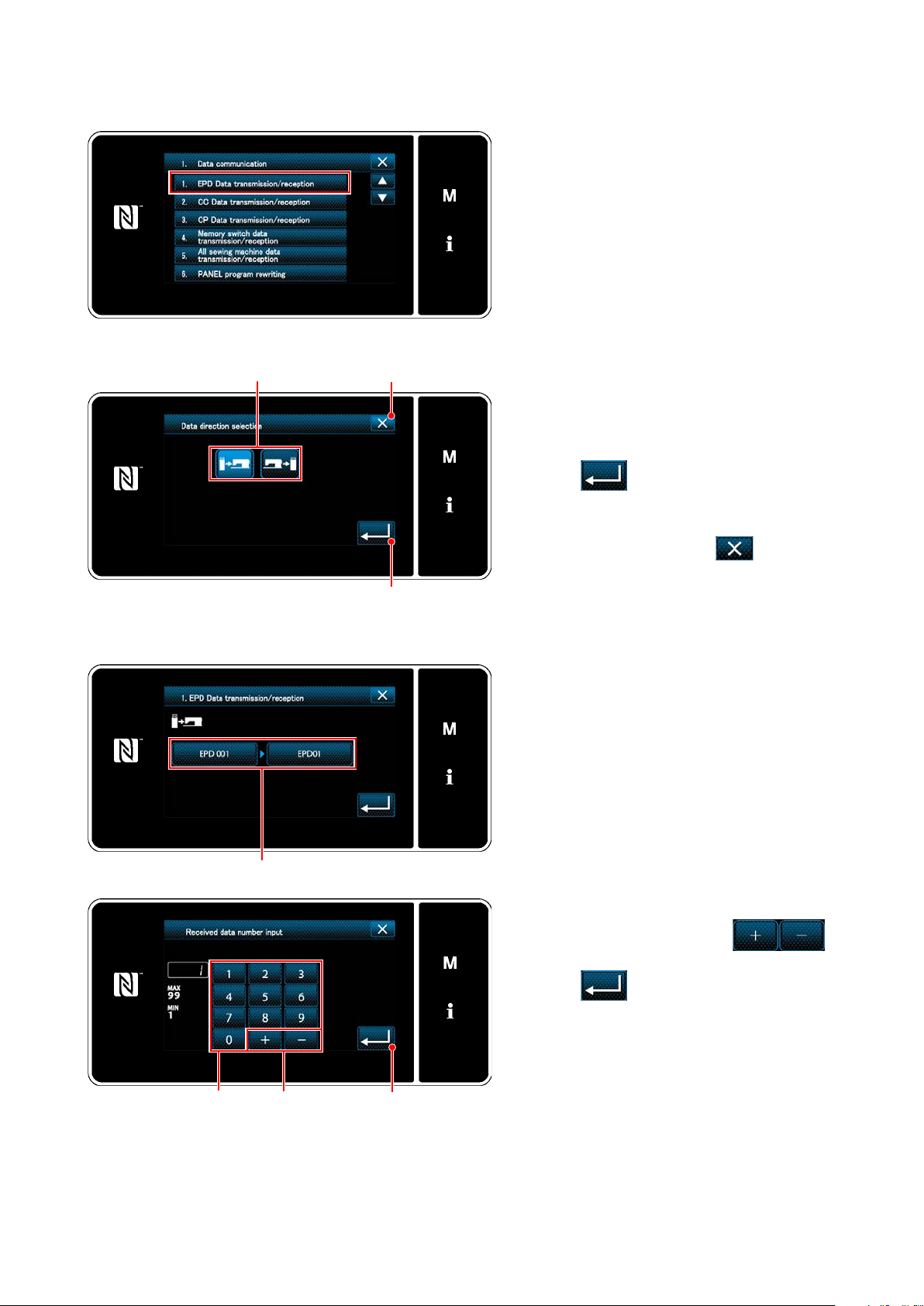
2)-2. When communication data is other than program data
② Selecting the data format used for communication
③ Selecting the communication direction
❶ ❸
❷
1. Select the transmitting/receiving data
format and press the selected data format
button.
For example, select "1. EPD data transmis-
sion/receipt".
The "data direction selection screen" is
displayed.
1. Select the communication direction. Press
button ❶ to put the communication direc-
tion in the selected state.
Press ❷ to conrm the setting.
The "data transmission/receipt preparation
screen" is displayed.
Cancel the operation with ❸. The cur-
rent screen returns to the previous screen.
④ Setting the data number and starting communication
❹
1. Press data number button❹.
The "data number input screen" is dis-
played.
2. Enter the source/destination data number
with numeric keypad ❺ and
❻.
Press ❼ to conrm the setting.
The "data transmission/receipt preparation
screen" is displayed.
❺
❻
❼
– 83 –
Page 100
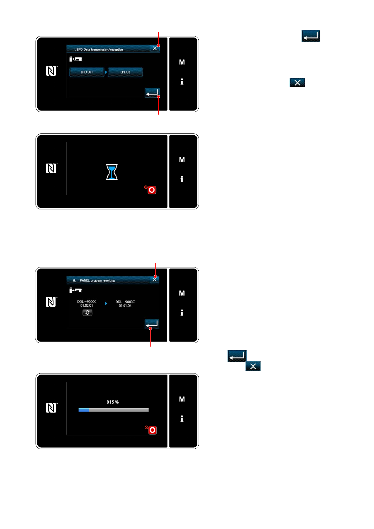
❽
❾
3.Conrm the numeric value with ❾ to
start communication.
"During communication" screen is dis-
played while the communication is being
carried out.
Cancel the operation with ❽. The cur-
rent screen returns to the previous screen.
* If the destination number you have
entered has already been registered,
the "overwrite conrmation message"
screen will be displayed.
4. While a program is being written, the
screen of such a situation is displayed.
2)-2. When communication data is program data
② Select the program to rewrite, and start communication.
❽
❾
1. After selection of data to communicate, the
program rewriting preparation screen is
displayed.
Press the program research key to change
program data that is being saved in the
USB memory.
2. After selection of the program data, press
the ❾ to start communication.
Press the ❽ to cancel operation,
and the current screen returns to the last
screen.
3. While a program is being written, the
screen of such a situation is displayed.
After such a writing of a program is com-
pleted, the screen giving you instructions
to turn off the sewing machine is displayed.
Turn off the machine.
4. When you turn on the sewing machine
again, the written program is executed.
– 84 –
 Loading...