

Page 1

DDL-8100B-7 Series
INSTRUCTION MANUAL
Page 2

CONTENTS
I. SPECIFICATIONS ........................................................................................ 1
II. SET-UP ........................................................................................................ 3
1. Installation ..........................................................................................................................................3
2. Installing the pedal sensor ................................................................................................................ 4
3. Connecting the connector .................................................................................................................4
4. How to install the power plug ...........................................................................................................5
5. Attaching the connecting rod ...........................................................................................................5
6. Winding the bobbin thread ................................................................................................................ 6
7. Adjusting the height of the knee lifter ..............................................................................................7
8. Installing the thread stand ................................................................................................................7
9. Lubrication .......................................................................................................................................... 8
10. Adjusting the amount of oil (oil splashes) .......................................................................................8
11. Attaching the needle ........................................................................................................................ 10
12. Setting the bobbin into the bobbin case ........................................................................................ 11
13. Adjusting the stitch length .............................................................................................................. 11
14. Presser foot pressure ...................................................................................................................... 11
15. Hand lifter ......................................................................................................................................... 11
16. Adjusting the height of the presser bar ......................................................................................... 12
17. Threading the machine head ..........................................................................................................12
18. Thread tension .................................................................................................................................13
19. Thread take-up spring .....................................................................................................................13
20. Adjusting the thread take-up stroke ...............................................................................................13
21. Needle-to-hook relationship ............................................................................................................14
22. Height of the feed dog .....................................................................................................................14
23. Tilt of the feed dog ...........................................................................................................................15
24. Adjusting the feed timing ................................................................................................................ 15
25. Cunter knife ......................................................................................................................................16
26. Pedal pressure and pedal stroke .................................................................................................... 16
27. Adjustment of the pedal ..................................................................................................................17
28. Marker dots on the handwheel .......................................................................................................17
III. FOR THE OPERATOR ............................................................................. 18
1. Operating procedure of the sewing machine ................................................................................ 18
2. Operation panel built in the machine head .................................................................................... 19
3. Operating procedure of the sewing pattern .................................................................................. 20
4. Setting of functions .........................................................................................................................22
5. Digital types operation ....................................................................................................................23
6. User Parameter & Technician Parameter .......................................................................................23
7. Details of setting of the main functions ......................................................................................... 26
8. Stitch balance of back-tacking for lockstitch machine ................................................................ 29
9. Error code list ................................................................................................................................... 32
i
Page 3

I. SPECIFICATIONS
Supply voltage Single phase 220V
Frequency 50Hz/60Hz
Operating environment
Input 210VA
Max. sewing speed 4,000 sti/min
Thread trimming speed 210 sti/min
Stitch length 5 mm
Presser foot lift (by knee lifter) 13 mm
Needle DB x 1 (#14) #14 to 18
Lubricating oil JUKI MACHINE OIL #7
Temperature : 5 to 35˚C
Humidity 35 - 85 % or less
– 1 –
Page 4
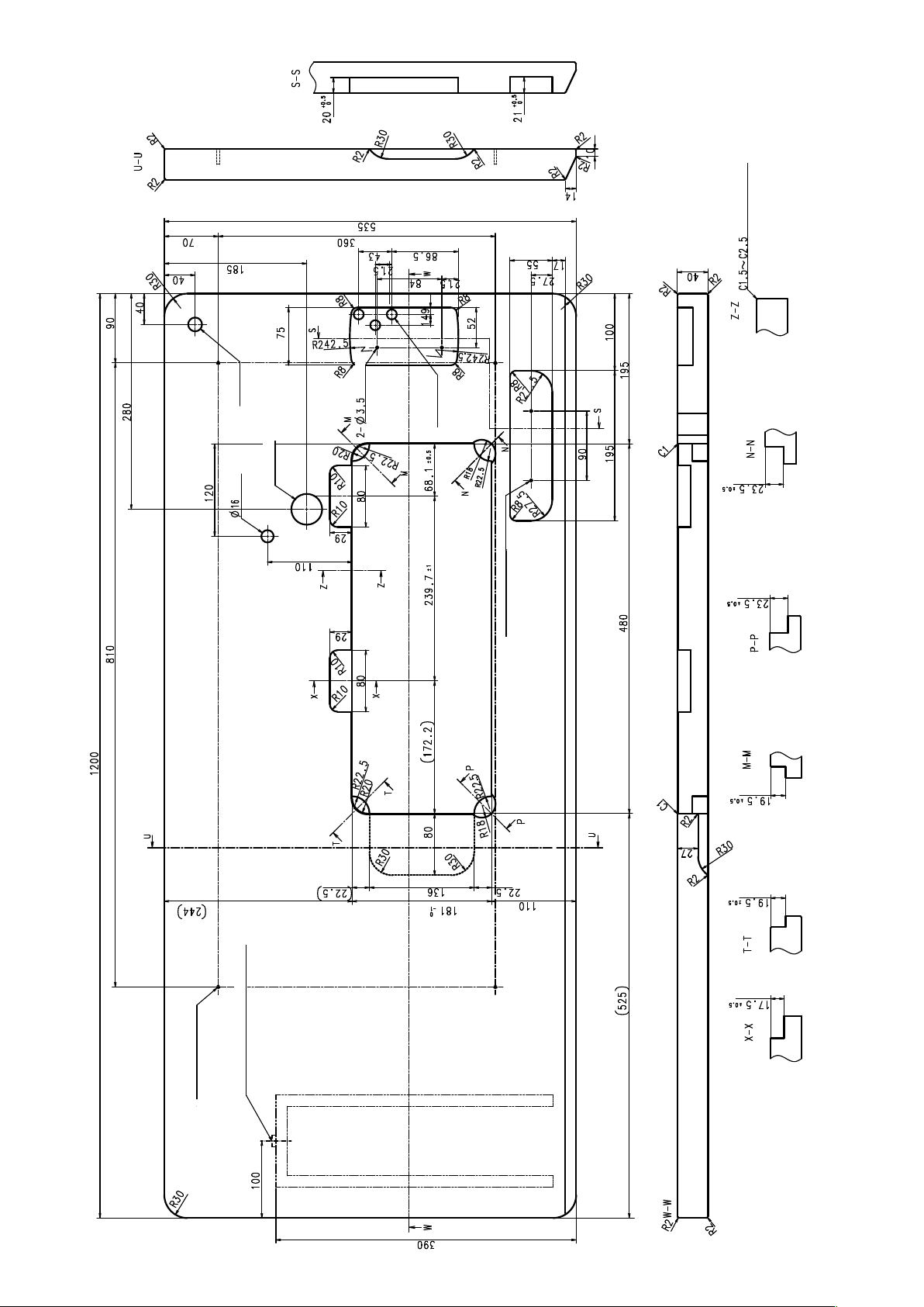
DRAWING OF TABLE
(Hinge side only)
ϕ18 Drilled hole
Drilled hole
0.5
±
40±0.5通し穴
ϕ40
depth 30
depth 10
3-ϕ13
Drilled hole
2-ø3.5 bottom surface, depth 10
Installing position of drawer stopper
(on the reverse side)
4-ϕ3.4 bottom surface, depth 20
(Drill a hole at the time of set-up.)
– 2 –
Page 5
II. SET-UP
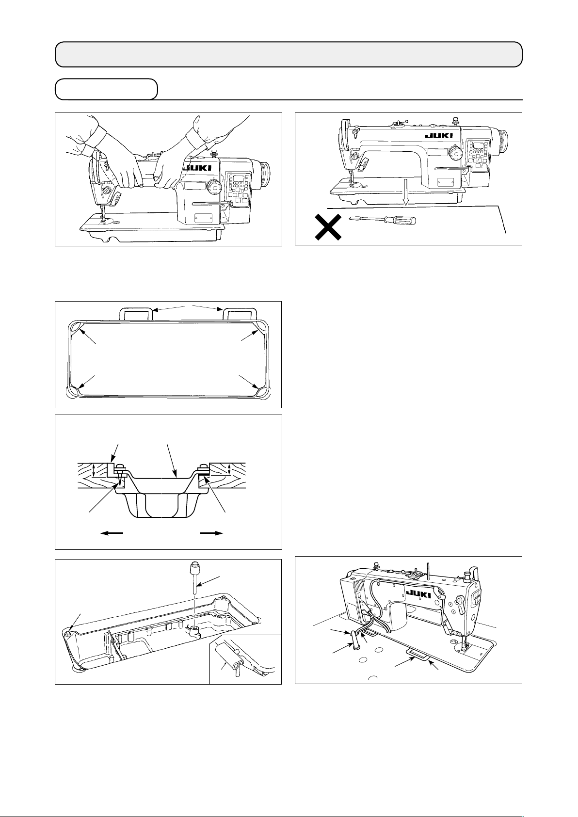
1. Installation
1) Carry the sewing machine with two persons as
shown in the gure above.
(Caution) Do not hold the handwheel.
❽
❸
❶
23.5mm
❷
❶
❹
A
B
❸
❶
19.5mm
❸
2) Do not put protruding articles such as the screw-
driver and the like at the location where the
sewing machine is placed.
3) Adjust so that the oil pan is supported at the four
corners of the table. Mount rubber hinge seat ❽
on the table and x it on the table with a nail.
4
) Two rubber seats ❶ for supporting the head por-
tion on the operator side A are xed on the extended portion of the table by hitting the nail ❷ ,
and the other two rubber cushion seats ❸ on the
hinge side B are xed by using a rubber-based
adhesive. Then, oil pan ❹ is placed.
❻
❾
❼
❽
❼
5) Fit knee lifter pressing rod ❻. Fit hinge ❼ into the opening in the machine bed, and t the machine head
to table rubber hinge ❽ before placing the machine head on cushions ❾ on the four corners.
6) Securely attach head support rod to the table until it goes no further.
* Be sure to install the machine head support bar supplied with the unit.
7) Draw out cable of the control box through cable draw-out hole to route it to the underside of the
sewing machine table.
– 3 –
Page 6
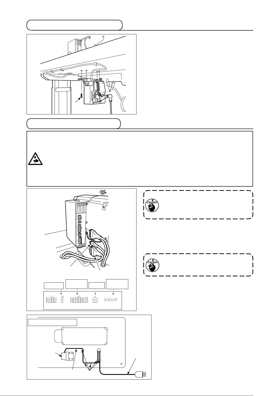
2. Installing the pedal sensor
❶
3. Connecting the connector
WARNING :
• To protect against personal injury resulting from abrupt start of the sewing machine, be sure to turn the
power OFF, unplug the machine and wait for ve minutes or more before installing the pedal sensor.
• To prevent damage of device caused by maloperation and wrong specications, be sure to connect
all the corresponding connectors to the specied places. (If any of the connectors is inserted into a
wrong connector, not only the device corresponding to the connector can break but also it can start
abruptly, inviting the risk of personal injury.)
• To prevent personal injury caused by maloperation, be sure to lock the connector with lock.
• As for the details of handling respective devices, read carefully the Instruction Manuals supplied
with the devices before handling the devices.
The explanation applies to the case the pedal sensor
is installed on the table for the DDL-8100B-7.
1) Install the pedal sensor to the table with mounting
screws ❶ supplied with the unit. It is necessary
to install the pedal sensor at such a position that
the connecting rod is perpendicular to the table.
2) After the completion of installation of the pedal
sensor on the table, place the sewing machine
head on the table.
❶
Connector connection diagram
Auto-lifter
Underside of the table
Solenoid &
LED/TB unit
Pedal
❷
Do not insert the power plug into the wall
outlet.
Check to be sure that the power switch is
turned OFF.
1) Connect pedal sensor cable ❶ and AC input
cable ❷ supplied with the unit to the control box.
Refer to the connector connection diagram for
connecting ports of the cables.
Be sure to fully insert the connectors into
the corresponding ports until they are
locked.
AC power
supply input
2) Fix the pedal cable and AC input cable
with a staple.
Pedal sensor
Pedal sensor cable
AC cable
Staples
– 4 –
Page 7
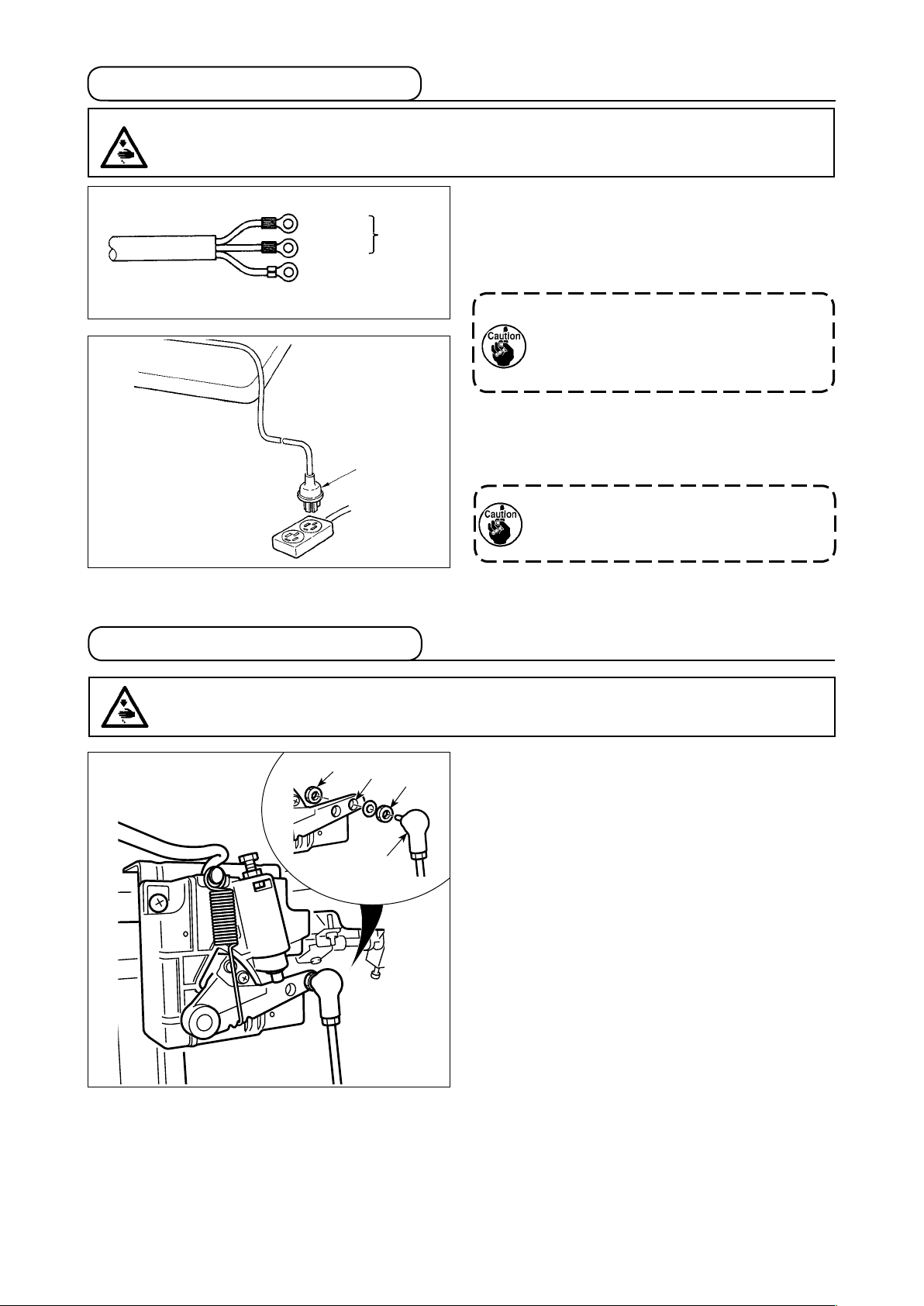
4. How to install the power plug
WARNING :
1. Be sure to attach the ground wire (green/yellow) to the specied location (on the ground side).
2. Take care not to allow terminals to come in contact with each other.
1ø 220V to 240V
Blue
Brown
Green / Yellow
(ground wire)
❶
5. Attaching the connecting rod
AC
220V to
240V
1) Connect the power cord to the power plug.
As shown in the gure, connect the brown and
blue wires to the power supply side and the
green/yellow one to the grounding side.
1. Be sure to prepare the power plug ❶
which conforms to the safety standard.
2. Be sure to connect the ground lead
(green/yellow) to the grounding side.
2) Check that the power switch is in the OFF state.
Then, insert the power plug coming from the pow-
er switch into the plug receptacle.
In prior to the connection of the power plug,
re-check the supply voltage specication
indicated on the control box.
WARNING :
To protect against possible personal injury due to abrupt start of the machine, be sure to start the
following work after turning the power off and a lapse of 5 minutes or more.
❸
❹
❸
❶
Fix connecting rod ❶ to installing hole B of pedal
lever ❷ with nut ❸.
– 5 –
Page 8
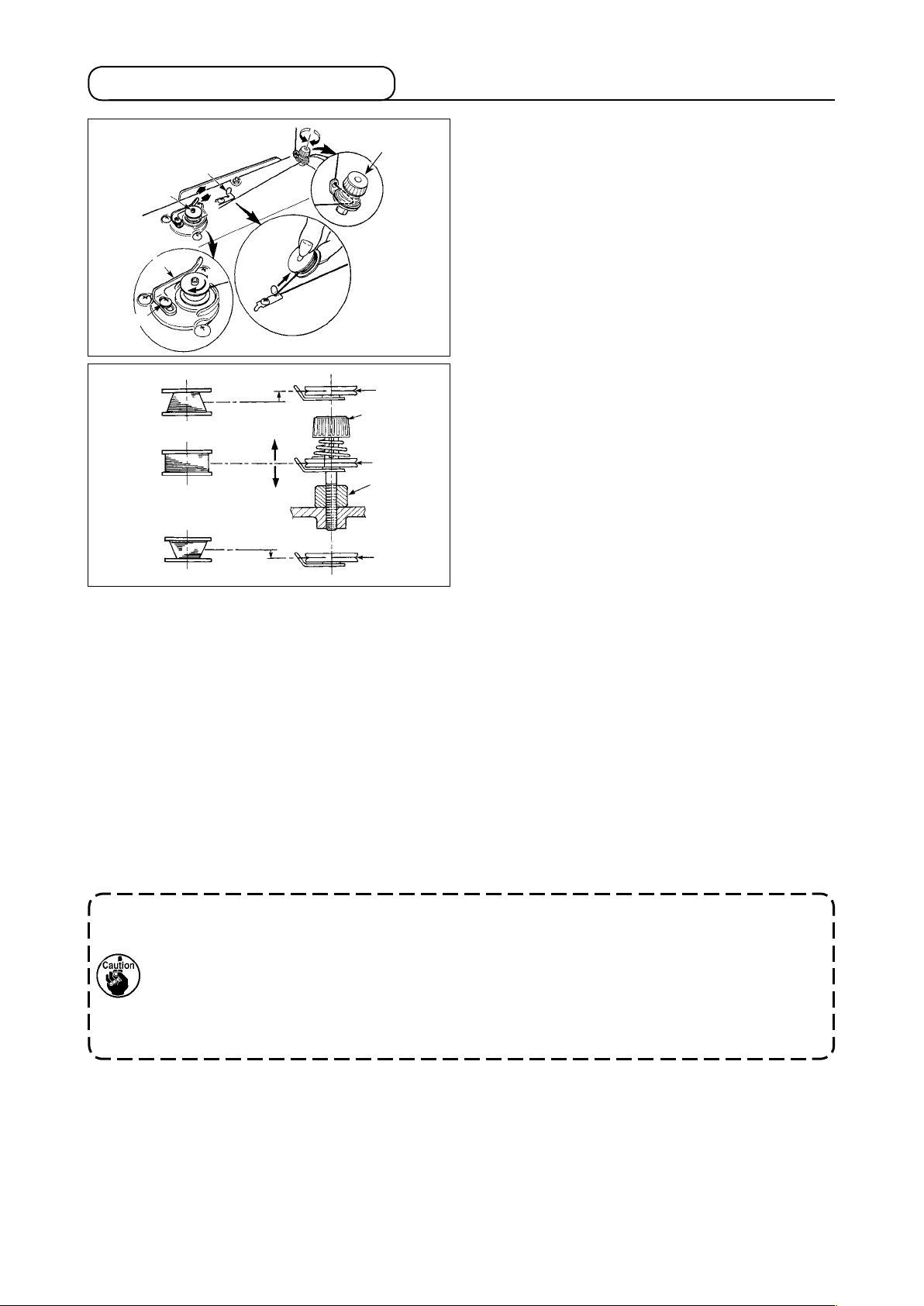
6. Winding the bobbin thread
1) Insert the bobbin deep into the bobbin winder
❽
❸
B
❶
❷
❹
A
C
❻
❼
D
❻
❺
E
❻
6) In case that the bobbin thread is not wound evenly on the bobbin, remove the handwheel, loosen screw
❺ and adjust the height of bobbin thread tension ❽.
• It is the standard that the center of the bobbin is as high as the center of thread tension disk ❻.
• Adjust the position of thread tension disk ❻ to the direction of D when the winding amount of the bobbin
thread on the lower part of the bobbin is excessive and to the direction E when the winding amount of the
bobbin thread on the upper part of the bobbin is excessive.
After the adjustment, tighten screw ❺.
7) To adjust the tension of the bobbin winder, turn the thread tension nut ❼.
spindle ❶ until it will go no further.
2) Pass the bobbin thread pulled out from the
spool rested on the right side of the thread stand
following the order as shown in the gure on the
left. Then, wind clockwise the end of the bobbin
thread on the bobbin several times.
(In case of the aluminum bobbin, after winding
clockwise the end of the bobbin thread, wind
counterclockwise the thread coming from the
bobbin thread tension several times to wind the
bobbin thread with ease.)
3) Press the bobbin winder trip latch ❷ in the direc-
tion of A and start the sewing machine. The bob-
bin rotates in the direction of C and the bobbin
thread is wound up. The bobbin winder spindle ❶
automatically as soon as the winding is nished.
4) Remove the bobbin and cut the bobbin thread
with the thread cut retainer ❸.
5) When adjusting the winding amount of the bobbin
thread, loosen setscrew ❹ and move bobbin
winding lever ❷ to the direction of A or B. Then
tighten setscrew ❹.
To the direction of A : Decrease
To the direction of B : Increase
1. When winding the bobbin thread, start the winding in the state that the thread between the
bobbin and thread tension disk ❻ is tense.
2. When winding the bobbin thread in the state that sewing is not performed, remove the needle
thread from the thread path of thread take-up and remove the bobbin from the hook.
3. There is the possibility that the thread pulled out from the thread stand is loosened due to
the inuence (direction) of the wind and may be entangled in the handwheel. Be careful of the
direction of the wind.
– 6 –
Page 9
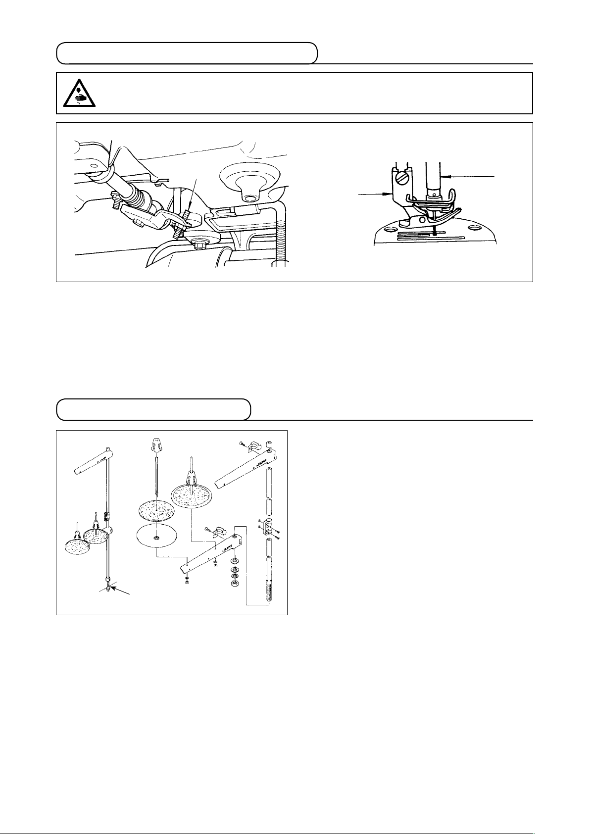
7. Adjusting the height of the knee lifter
WARNING :
Be sure to turn the power OFF before the following work in order to prevent personal injury due to
unintentional starting of the sewing machine.
❶
❸
❷
1) The standard height of the presser foot lifted using the knee lifter is 10 mm.
2) You can adjust the presser foot lift up to 13 mm using knee lifter adjust screw ❶.
3) When you have adjusted the presser foot lift to over 10 mm, be sure that the bottom end of needle bar ❷
in its lowest position does not hit presser foot ❸.
8. Installing the thread stand
1) Assemble the thread stand unit, and insert it in
the hole in the machine table.
2) Tighten nut ❶.
❶
– 7 –
Page 10
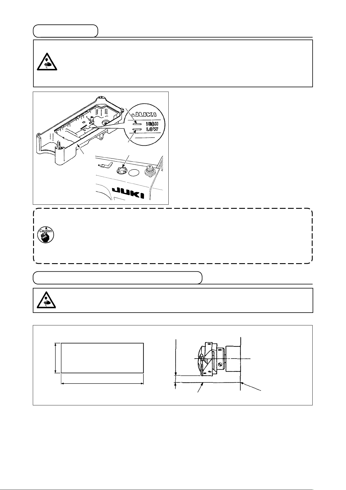
9. Lubrication
WARNING :
1. Do not connect the power plug until the lubrication has been completed so as to prevent
accidents due to abrupt start of the sewing machine,
2. To prevent the occurrence of an inammation or rash, immediately wash the related portions if
oil adheres to your eyes or other parts of your body.
3. If oil is mistakenly swallowed, diarrhea or vomitting may occur. Put oil in a place where children
cannot reach.
❶
1) Before starting the sewing machine, ll oil pan ❶
A
with JUKI MACHINE OIL #7 up to HIGH mark A.
2) Add oil before the oil surface comes down to
reach the LOW mark B.
3) When you operate the machine after lubrication,
you will see splashing oil through oil sight window
B
❷
❷ if the lubrication is adequate.
4) Note that the amount of the splashing oil is unre-
lated to the amount of the lubricating oil.
1. When you use a new sewing machine or a sewing machine after an extended period of disuse,
use the sewing machine after performing break-in at 2,000 sti/min or less.
2. For the oil lubrication, purchase JUKI NEW DEFRIX OIL No. 1 (Part No. : MDFRX1600C0) or
JUKI MACHINE OIL #7 (Part No. : MML007600CA).
3. Be sure to lubricate clean oil.
4. When the oil surface is lower than the LOW mark, the oiling may be inconsistent. To prevent
inconsistent oiling, add oil before the oil surface comes down to reach the LOW mark.
10. Adjusting the amount of oil (oil splashes)
WARNING :
Be extremely careful about the operation of the machine since the amount of oil has to be checked
by turning the hook at a high speed.
(1) Conrmation of the amount of oil in the hook
Amount of oil (oil splashes) conrmation paper
①
25 mm
70 mm
Oil splashes conrmation paper
Position to conrm the amount of oil (oil splashes)
②
3 - 10 mm
Closely fit the
paper against the
wall surface of the
bed.
* When carrying out the procedure described below in 2, remove the slide plate and take extreme caution
not to allow your ngers to come in contact with the hook.
1) If the machine has not been sufciently warmed up for operation, make the machine run idle for approxi-
mately three minutes. (Moderate intermittent operation)
2) Place the amount of oil (oil spots) conrmation paper under the hook immediately after the machine stops
running.
3) Conrm the height of the oil surface in the oil reservoir is within the range between “HIGH” and “LOW”.
4) Conrmation of the amount of oil should be completed in ve seconds. (Check the period of time with a
watch.)
– 8 –
Page 11
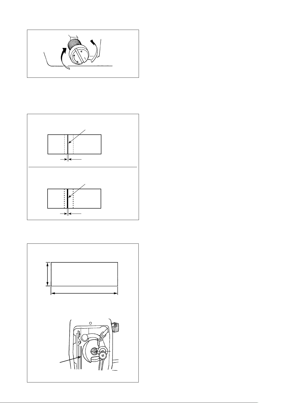
(2) Adjusting the amount of oil (oil spots) in the hook
1) Turning the oil amount adjustment screw attached
on the hook driving shaft front bushing in the “+”
direction (in direction A) will increase the amount of
oil (oil spots) in the hook, or in the “–” direction (in
B
A
direction B) will decrease it.
2) After the amount of oil in the hook has been prop-
erly adjusted with the oil amount adjustment screw,
make the sewing machine run idle for approximate-
ly 30 seconds to check the amount of oil in the
hook.
(3) Sample showing the appropriate amount of oil in the hook
Appropriate amount of oil (small)
Splashes of oil from the hook
should be nely adjusted in accordance with sewing
processes.
Be careful not to excessively increase/decrease the
amount of oil in the hook. (If the amount of oil is too
small, the hook will be seized (the hook will be hot).
1) The amount of oil shown in the samples on the left
1 mm
If the amount of oil is too much, the sewing product
may be stained with oil.)
Appropriate amount of oil (large)
Splashes of oil from the hook
2) Adjust the amount of oil in the hook so that the
oil amount (oil splashes) should not change while
checking the oil amount three times (on the three
sheets of paper).
2 mm
(4) Conrmation of the amount of oil supplied to the face plate parts
Amount of oil (oil splashes) conrmation paper
①
25 mm
70 mm
Position to conrm the amount of oil
②
(oil splashes)
Oil splashes
conrmation paper
* When carrying out the work described below in
2), remove the face plate and take extreme cau-
tion not to allow your ngers to come in contact
with the thread take-up lever.
1) If the machine has not been sufciently warmed
up for operation, make the machine run idle for
approximately three minutes. (Moderate intermit-
tent operation)
2) Place the amount of oil (oil spots) conrmation
paper under the hook immediately after the ma-
chine stops running.
3) Conrm the height of the oil surface in the oil
reservoir is within the range between “HIGH” and
“LOW”.
4) The time required for the conrmation of the
amount of oil (oil splashes) should be completed
in ten seconds. (Measure the period of time with
a watch.)
– 9 –
Page 12

(5) Adjusting the amount of oil supplied to the face plate parts
1) Adjust the amount of oil supplied to the thread
take-up and needle bar crank ❷ by turning adjust
pin ❶.
C
maximum
B
❶
minimum
A
2) The minimum amount of oil is reached when
marker dot A is brought close to needle bar
❷
crank ❷ by turning the adjust pin in direction B.
3) The maximum amount of oil is reached when
marker dot A is brought to the position just
❶
opposite from the needle bar crank by turning the
adjust pin in direction C.
(6) Sample showing the appropriate amount of oil supplied to the face plate parts
Appropriate amount of oil (small)
S
plashes of oil from the thread take-up lever
1 mm
Appropriate amount of oil (large)
S
plashes of oil from the thread take-up lever
2 mm
11. Attaching the needle
WARNING :
Be sure to turn the power OFF before the following work in order to prevent personal injury due to
unintentional starting of the sewing machine.
1) The state given in the gure shows the appropri-
ate amount of oil (oil splashes). It is necessary to
nely adjust the amount of oil in accordance with
the sewing processes. However, do not excessively increase/decrease the amount of oil in the
hook. (If the amount of oil is too small, the hook
will be seized (the hook will be hot). If the amount
of oil is too much, the sewing product may be
stained with oil.)
2) Adjust the amount of oil in the hook so that the
oil amount (oil splashes) should not change while
checking the oil amount three times (on the three
sheets of paper).
Use the specied needle for the machine. Use the
proper needle in accordance with the thickness of
D
B
thread used and the kinds of the materials.
1) Turn the handwheel until the needle bar reaches
the highest point of its stroke.
❶
C
A
❷
2) Loosen screw ❷, and hold needle ❶ with its
indented part A facing exactly to the right in
direction B.
3) Insert the needle fully into the hole in the needle
bar in the direction of the arrow until the end of
hole is reached.
4) Securely tighten screw ❷.
5) Check that long groove C of the needle is facing exactly to the left in direction D.
When polyester lament thread is used, if the indented part of the needle is tilted toward operator's
side, the loop of thread becomes unstable. As a result, hangnail of thread or thread breakage may
occur. For the thread that such phenomenon is likely to occur, it is effective to attach the needle
with its indented part slightly slanting on the rear side.
– 10 –
Page 13

12. Setting the bobbin into the bobbin case
A
B
C
13. Adjusting the stitch length
A
❶
1) Pass the thread through thread slit A, and pull
the thread in direction C. By so doing, the thread
will pass under the tension spring and come out
from notch B.
2) Check that the bobbin rotates in the direction of
the arrow when thread is pulled.
* The dial calibration is in millimeters.
1) Turn stitch length dial ❶ in the direction of the
arrow, and align the desired number to marker
dot A on the machine arm.
14. Presser foot pressure
B
29 to 32 mm
A
❶
❶
15. Hand lifter
1) Loosen nut ❷. As you turn presser spring regulator ❶ clockwise (in direction A), the presser foot
pressure will be increased.
2) As you turn the presser spring regulator counter-clockwise (in direction B), the pressure will be
decreased.
3) After adjustment, tighten nut ❷.
The standard value of the pressure regulating thumb
screw is 29 to 32 mm.
1) The presser foot is lifted by moving the lever
upward.
2) The presser foot is lowered by moving the lever
downward.
– 11 –
Page 14

16. Adjusting the height of the presser bar
WARNING :
Be sure to turn the power OFF before the following work in order to prevent personal injury due to
unintentional starting of the sewing machine.
❶
17. Threading the machine head
WARNING :
Be sure to turn the power OFF before the following work in order to prevent personal injury due to
unintentional starting of the sewing machine.
1) Loosen setscrew ❶, and adjust the presser bar
height or the angle of the presser foot.
2) After adjustment, securely tighten the setscrew
❶.
– 12 –
Page 15

18. Thread tension
❶
B
A
❷
C
D
19. Thread take-up spring
❶
❷
A
B
❸
❸
E
❶
❺
F
❹
(1) Adjusting the needle thread tension
1) The length of thread remaining at the needle tip
after thread trimming is shortened by turning tension regulating nut No. 1 ❶ clockwise in direction
A.
2) It is lengthened by turning the nut counterclockwise in direction B.
3) The needle thread tension is increased by turning
tension regulating nut No. 2 ❷ clockwise in direction C.
4) It is decreased by turning the nut counterclockwise in direction D.
(2) Adjusting the bobbin thread tension
1) The bobbin thread tension is increased by turning
tension regulating screw ❸ clockwise in direction
E.
2) It is decreased by turning the screw counterclockwise in direction F.
(1) Changing the stroke of thread take-up spring ❶
1) Loosen setscrew ❷.
2) As you turn tension post ❸ clockwise (in direction A), the stroke of the thread take-up spring
will be increased.
3) As you turn the knob counterclockwise (in direction B), the stroke will be decreased.
(2) Changing the pressure of thread take-up
spring ❶
1) Loosen setscrew ❷, and remove thread tension
❸.
2) Loosen setscrew ❹.
3) As you turn tension post ❸ clockwise (in direction A), the pressure will be increased.
4) As you turn the tension post counterclockwise (in
direction B), the pressure will be decreased.
20. Adjusting the thread take-up stroke
WARNING :
Be sure to turn the power OFF before the following work in order to prevent personal injury due to
unintentional starting of the sewing machine.
BA
❶
C
1) When sewing heavy-weight materials, move
thread guide ❶ to the left (in direction A) to
increase the length of thread pulled out by the
thread take-up.
2) When sewing light-weight materials, move thread
guide ❶ to the right (in direction B) to decrease
the length of thread pulled out by the thread takeup.
3) Normally, thread guide ❶ is positioned in a way
that marker line C is aligned with the center of
the screw.
– 13 –
Page 16

21. Needle-to-hook relationship
WARNING :
Be sure to turn the power OFF before the following work in order to prevent personal injury due to
unintentional starting of the sewing machine.
❶
❹
❸
A
❷
❺
B
A
B
0.04 to 0.1 mm
a
(1) Adjust the timing between the needle and the
hook as follows :
1) Turn the handwheel to bright the needle bar
down to the lowest point of its stroke, and loosen
setscrew ❶.
(Adjusting the needle bar height)
2) Align marker line A on needle bar ❷ with the
bottom end of needle bar lower bushing ❸, then
tighten setscrew ❶.
(Adjusting position of the hook a)
3) Loosen the three hook setscrews, turn the
handwheel and align marker line B on ascending
needle bar ❷ with the bottom end of needle bar
lower bushing ❸.
4) After making the adjustments mentioned in the
above steps, align hook blade point ❺ with the
center of needle ❹. Provide a clearance of 0.04
mm to 0.1 mm (reference value) between the
needle and the hook, then securely tighten setscrews in the hook.
If the clearance between the blade point of hook and the needle is smaller than the specied
value, the blade point of hook will be damaged. If the clearance is larger, stitch skipping will
result.
22. Height of the feed dog
WARNING :
Be sure to turn the power OFF before the following work in order to prevent personal injury due to
unintentional starting of the sewing machine.
To adjust the height of the feed dog :
① Loosen screw ❷ of crank ❶.
❶
0.75 to 0.85 mm
❷
② Move the feed bar up or down to make adjust-
ment.
③ Securely tighten screw ❷.
If the clamping pressure is insufcient,
the motion of the forked portion becomes
heavy.
– 14 –
Page 17

23. Tilt of the feed dog
WARNING :
Be sure to turn the power OFF before the following work in order to prevent personal injury due to
unintentional starting of the sewing machine.
B
A
❶
Front up
a
Front down
c
b
Standard
Throat plate
d
b
c
a
d
1) The standard tilt (horizontal) of the feed dog is
obtained when marker dot A on the feed bar
shaft is aligned with marker dot B on feed rocker
❶.
2) To tilt the feed dog with its front up in order to
prevent puckering, loosen the setscrew, and
turn the feed bar shaft 90˚ in the direction of the
arrow, using a screwdriver.
3) To tilt the feed dog with its front down in order to
prevent uneven material feed, turn the feed bar
shaft 90˚ in the opposite direction from the arrow.
Whenever the feed dog tilt is adjusted,
the feed dog height will be changed. So,
it is necessary to check the height after
tilt adjustment.
24. Adjusting the feed timing
WARNING :
Be sure to turn the power OFF before the following work in order to prevent personal injury due to
unintentional starting of the sewing machine.
❶
❶
❶
Standard feed timing
Advanced feed timing
Delayed feed timing
1) Loosen screws ❷ and ❸ in feed eccentric cam
❶, move the feed eccentric cam in the direction
of the arrow or opposite direction of the arrow,
and rmly tighten the screws.
2)
For the standard adjustment, adjust so that the
top surface of feed dog and the top end of needle
eyelet are ush with the top surface of throat plate
when the feed dog descends below the throat
plate.
3) To advance the feed timing in order to prevent
uneven material feed, move the feed eccentric
cam in the direction of the arrow.
4) To delay the feed timing in order to increase
stitch tightness, move the feed eccentric cam in
the opposite direction from the arrow.
Be careful not to move the feed eccentric
cam too far, or else needle breakage may
result.
– 15 –
Page 18

25. Cunter knife
WARNING :
Be sure to turn the power OFF before the following work in order to prevent personal injury due to
unintentional starting of the sewing machine.
When sharpening again the knife blade, extra special care must be taken on the handling of the
knife.
If the knife does not cut thread sharply, immediately
re-sharpen counter knife ❶ as illustrated in Fig. A and
re-install it properly.
1) If the mounting position of the counter knife is
moved in direction A from the standard mounting
position, the thread length after thread trimming
will be increased accordingly.
2) If the mounting position is moved in direction B,
the thread length will be decreased accordingly.
Fig A
❶
Moving knife
a
Standard : 4.0mm
c
a
b
c
B
Center of needle
b
❶
A
[DDL-8100B-7R]
Fig A
❶
Oil Stone
❷
❸
❶
❹
* In the case the thread cannot be trimmed sharply, re-sharpen counter knife ❶ as illustrated in Fig. A be-
fore the knife has become dull and re-place it correctly.
1) Loosen setscrew ❷ of bobbin case opening lever ❶, and remove the bobbin case opening lever.
2) Loosen setscrew ❹, and remove counter knife ❸.
3) To install the counter knife, follow the above procedure in reverse order.
4) When attaching the bobbin case opening lever, tighten the setscrew while pressing the lever in direction A.
26. Pedal pressure and pedal stroke
WARNING :
Be sure to turn the power OFF before the following work in order to prevent personal injury due to
unintentional starting of the sewing machine.
For General Application
B
C
A
Adjust the force required to operate the foot pedal
Spring A : Downward force adjustment
Bolt B : Heeling back force adjustment
Hole C : Pedal stroke adjustment
– 16 –
Page 19

27. Adjustment of the pedal
WARNING :
Be sure to turn the power OFF before the following work in order to prevent personal injury due to
unintentional starting of the sewing machine.
❶
❶
(1) Installing the connecting rod
1) Move pedal ❸ to the right or left as illustrated
by the arrows so that motor control lever ❶ and
connecting rod ❷ are straightened.
(2) Adjusting the pedal angle
❶
1) The pedal tilt can be freely adjusted by changing
the length of the connecting rod.
2) Loosen adjust screw ❹, and adjust the length of
❶
connecting rod ❺.
28. Marker dots on the handwheel
(Blue)
❶
❷
(White)
❸
❹
❺
(Green)
(Red)
❶
The upper stop position of the needle bar is reached
when marker dot ❶ on the cover is aligned with white
marker dot ❸ on the handwheel.
The operating timing of the thread trimming cam is
when marker dot ❶ on the cover is aligned with red
marker dot ❺ on the handwheel.
– 17 –
Page 20

III. FOR THE OPERATOR
1. Operating procedure of the sewing machine
❶
1) Press ON button ❶ of the power switch to turn
ON the power.
The power switch is in its ON state when the "I"
mark is pressed. It is in its OFF state when the
"○" mark is pressed.
If the power indicator LED on the panel does
not light up after having turned ON the power
switch, immediately turn OFF the power switch
and check the supply voltage. In addition, in
such a case as this, re-turn ON the power
switch when 2 to 3 minutes or more have
passed after turning OFF the power switch.
2) When the needle bar is not in UP position, it
automatically turns to the UP position.
When turning ON the power, the needle bar moves.
Do not put your hands or things under the needle.
❸
❹
3) The pedal is operated in the following four steps:
a. The machine runs at low sewing speed when you
❷
lightly depress the front part of the pedal. ❷
b.
The machine runs at high sewing speed when
you further depress the front part of the pedal. ❷
(If the automatic reverse feed stitching has been
preset, the machine runs at high speed after it
completes reverse feed stitching.)
c. The machine stops (with its needle up or down) when you reset the pedal to its original position.
d. The machine trims threads when you fully depress the back part of the pedal. ❹
* When the auto-lifer (AK device) is used, one more operating switch is provided between the sewing ma-
chine stop switch and thread trimming switch. The presser foot goes up when you lightly depress the back
part of the pedal ❸, and if you further depress the back part ❹, the thread trimmer is actuated.
When starting sewing from the state that the presser foot has been lifted with the Auto-lifter and you depress the back part of the pedal, the presser foot only comes down.
❼
❺
4) Reverse feed stitching at the beginning of sewing,
reverse feed stitching at the end of sewing and
various sewing patterns can be set on built-in panel
❺
of the machine head.
5) When one-touch type reverse feed switch ❻ is
pressed, the sewing machine performs reverse
feed stitching. The quantity of light of the LED
can be adjusted by turning control knob ❼.
❻
6) When sewing is completed, press OFF button ❶ of the power switch to turn OFF the power switch after
conrming that the sewing machine has stopped.
In the case the machine is not used for a long time, remove the power plug from the plug receptacle.
– 18 –
Page 21

2. Operation panel built in the machine head
Display section
Ⓐ
Ⓑ
ⒹⒸ
Ⓔ
Ⓕ
❶
Ⓖ
❷
Ⓗ
❸
Ⓘ
❹
Ⓙ
❺
Ⓟ
Ⓚ
❻
Ⓛ
❼
Ⓜ
❽
Ⓝ
❾
Ⓞ
Ⓠ
Used to change over the automatic reverse
❶
❷
❸
❹
❺
❻
❼
feed stitching at the beginning of sewing between enable and disable
Used to change over the automatic reverse
feed stitching at the end of sewing between
enable and disable
Used to change over the automatic double
reverse feed stitching at the beginning of
sewing between enable and disable
Used to change over the automatic double
reverse feed stitching at the end of sewing
between enable and disable
Used to change over the reverse feed stitching pattern between enable and disable
Used to change over the overlapped stitching
pattern between enable and disable
❽
Used to change over the constant-dimension
stitching pattern between enable and disable
❾
Used to change the contents displayed on
the display section
Used to change over the needle bar stop
position at the time of stopping sewing be-
tween up and down
Used to carry out compensating stitching in
half-stitch steps
Used to change over the thread trimming
operation between enable and disable
Used to change over the auto-lifter function,
while the pedal is in its neutral position,
between enable and disable
Used to change over the auto-lifter function
after thread trimming between enable and
disable
Used to change over the soft-start function
between enable and disable
Used to change over the one-shot automatic
stitching between enable and disable
Used to change over the operation mode to
the function setting mode
*1
*1
Used to conrm the settings changed under
*1
The status of switches and is changed over by keeping them held pressed for three seconds.
the function setting mode
– 19 –
Page 22

3. Operating procedure of the sewing pattern
Refer to the Instruction Manual for each operation panel for how to operate sewing patterns using
other operation panel than the built-in panel of the machine head.
(1) Reverse feed stitching pattern
Reverse feed stitching at sewing start and reverse feed stitching at sewing end can be separately pro-
grammed.
Ⓐ
[Setting procedure of the reverse feed stitching]
1) Effective/ineffective of the reverse feed stitching
pattern can be changed over by pressing
switch ❺.
When the reverse feed stitching pattern is en-
❶
❷
Ⓚ
❻
❼
abled, LED Ⓙ lights up and the display section
❸
❹
Ⓙ
❺
❽
❾
Ⓞ
Ⓐ shows the number of reverse feed stitches at
the beginning of sewing and that at the end of
sewing.
Use and switches to change the num-
ber of stitches for the target process (A, B, C or
D). (The number of stitches that can be set is 0 to
15.)
The numbers of stitches for processes A, B, C
and D are displayed on display section Ⓐ from
left to right in the order from A to D.
2) Enable/disable of the reverse feed stitching at
the beginning of sewing is set by pressing
switch ❶.
Enable/disable of the reverse feed stitching at the end of sewing is set by pressing switch ❷.
Enable/disable of the double reverse feed stitching at the beginning of sewing is set by pressing
switch ❸.
Enable/disable of the double reverse feed stitching at the end of sewing is set by pressing switch ❹.
(2) Overlapped stitching pattern
Overlapped stitching pattern can be programmed.
A
B
C
B
D
C
1) Effective/ineffective of the overlapped stitching pattern can be changed over by pressing switch ❻.
When the overlapped stitching pattern is rendered effective, LED Ⓚ lights up.
2) Press and switches to change the number of stitches for target process (A, B, C or D).
A : Number of stitches of normal stitching setting
0 to 15 stitches
B : Number of stitches of reverse stitching setting
0 to 15 stitches
C : Number of stitches of normal stitching setting
0 to 15 stitches
D : Number of times of repetition
0 to 15 times
When process D is set to 5 times, the sewing is repeated
as A → B → C → B → C.
– 20 –
Page 23

(3) Constant-dimension stitching pattern
The constant-dimension stitching pattern can be set.
[How to set the constant-dimension stitching]
* Straight stitching
1) Enable/disable of the constant-dimension stitching pattern can be changed over by pressing switch
.
When the constant-dimension stitching pattern is enabled, LED Ⓞ lights up.
Immediately after the constant-dimension stitching is enabled, the numbers of reverse feed stitching pro-
cesses (A, B, C and D) are displayed on the display section Ⓐ.
2) When switch is pressed, the content shown on display section is changed over to the number of
stitches for the constant-dimension stitching.
The number of stitches (0 to 99) for the constant-dimension stitching can be selected by pressing
switch .
* Others
1) Enable/disable of each stitching pattern can be changed over by pressing switch ❼, switch
❽ or switch ❾.
Immediately after one of the stitching patterns is enabled, the numbers of reverse feed stitching process-
es (A, B, C and D) are displayed on the display section Ⓐ.
2) When switch is pressed, the display section Ⓐ changes its display to the number of stitches for
the constant-dimension stitching process (EF) is displayed.
The number of stitches for the process (EF) can be set by pressing switch .
3) Then, the content shown on display section Ⓐ is changed over to the number of stitches for the con-
stant-dimension stitching process (GH) by pressing switch .
The number of stitches (0 to 99) for the process (GH) can be set by pressing switch .
4) When switch is pressed, the content shown on display section Ⓐ is changed over to the num-
bers of stitches for the reverse feed stitching processes (A, B, C and D).
– 21 –
Page 24

4. Setting of functions
Functions can be selected and specied.
Refer to the Instruction Manual for each operation panel for how to operate sewing patterns using
other operation panel than the built-in panel of the machine head.
Ⓐ
1) Press switch .
The content on display section Ⓐ is changed
over to display function setting number (P-**).
(The display item which was previously changed
is displayed unless the power has not been
turned off after the previous change.)
* If the screen display does not change, re-carry
out operation described in step 1).
Be sure to re-turn ON the power switch when
ten or more seconds have passed after turn-
ing it OFF. If the power switch is re-turned ON
immediately after turning it OFF, the sewing
machine may fail to operate normally. In such
a case, be sure to turn ON the power switch
again properly.
2) To change the function setting number press switch and change it to a desired one.
3) After having changed the function setting number to a desired one, press switch to display the
set value of the selected function setting No.
4) Press switch to change the set value.
5) Press switch to conrm the set value.
Example) To change the setting No. P-01 "the maximum number of revolutions":
Press switch to change over to the setting number display.
Press switch to select setting number P-01. Press switch to conrm the number.
The current set value (maximum number of revolutions) of function setting number P-01 is displayed.
Change the maximum number of revolutions with switch and conrm the set value.
Then, conrm the setting with switch .
– 22 –
Page 25

5. Digital types operation
(1) Comparison Table of LCD Display Fonts and Actual Fonts
Arabic Numerals:
Actual 0 1 2 3 4 5 6 7 8 9
Display
(2) Digital Display on the Key Board
English Alphabet
Actual A B C D E F G H I J K L M
Display
Actual N O P Q R S T U V W X Y Z
Display
6. User Parameter & Technician Parameter
Parame-
ter code
P01
P02
p03
p04
P05
P06
P07
P08
P09
P10 Automatic end
Parameter function Range/ unit Default Key Description
Maximum sewing
speed (sti/min)
Speed curve adjust-
ment(%)
Needle UP/ DOWN
Start back-tacking
speed (sti/min)
End back-tacking
speed (sti/min)
Bar-tacking speed
(sti/min)
Soft start speed (sti/
min)
Stitch numbers for
soft start(sls)
Automatic con-
stant-stitch sewing
speed (sti/min)
back-tacking sew-
ing(can invalidate
the stitch correction
function)
100 to 4000 3500
1 to100% 80
uP / DN DN
200 to 3200 1900
200 to 3200 1900
200 to 3200 1900
200 to 1500 800
0 to 99 Stitch-es4
200 to 4000 3500
ON / OFF ON The Stitch-Correction is valid in sewing stop.
Maximum speed of machine sewing
The lager the value, the faster to increase
speed
Up: Needle stops at up position
Dn: Needle stops at down position
Start Back-Tacking speed adjustment
End Back-Tacking speed adjustment
Repeat Bar-Tacking speed adjustment
Soft Start speed adjustment
Soft Start stitches setting (one unit = half
stitch)
Constant-Stitch sewing speed [034.SMP] is
set at A(or when one shot signal is active)
Note : Valid only when the【0.11.RVM】must
set on B
ON : Invalid (Constant-Stitch sewing, it can
automatic continue action as CD func-
tion)
OFF : Valid (Can’t continue execute CD func-
tion)
– 23 –
Page 26

Parame-
ter code
P11 Back-Tacking mode
P12 Start Back-Tacking
P13 Mode selection at
P14 Soft start ON / OFF ON Add with full-function operation panel is valid.
P15 Setting stitches A of
P16 Setting stitches B of
P17 Setting turns of
P18 Stitch balance for
P19 Stitch balance for
P20 Mode selection for
P21 End Back-Tacking
P22 Setting stitches C of
P23 Setting stitches D of
P24 Setting turns of End
P25 Stitch balance for
P26 Stitch balance for
P27 Adding 1 stitch to
P28 Mode selection for
Parameter function Range/ unit Default Key Description
J / B J Press Back-Tacking switch by hand:
selection
mode selection
the end of Start
Back-Tacking
Start Back-Tacking
Start Back-Tacking
Start Back-Tacking
Start Back-Tacking
1
Start Back-Tacking
2
End Back-Tacking
function selection
End Back-Tacking
End Back-Tacking
Back-Tacking
End Back-Tacking 3
End Back-Tacking 4
C segment of End
Back-Tacking
Bar-Tacking
A / M A Start Back-Tacking, reverse solenoid action:
CON / STP CON CON : At the end of Start Back-Tacking,
1 to 15 Stitches Reserve Invalid,setting by front shortcut key
1 to 15 Stitches Reserve Invalid,setting by front shortcut key
1 to 4 Times Reserve Invalid,setting by front shortcut key
0 to 31 6
0 to 31 9
A/M
ON / OFF Reserve Invalid,setting by front shortcut key
1 to 15 Stitches Reserve Invalid,setting by front shortcut key
1 to 15 Stitches Reserve Invalid,setting by front shortcut key
1 to 4 Times Reserve Invalid,setting by front shortcut key
0 to 31 12
ON / OFF ON Adding 1 Stitch to C Segment of End
A/M A Bar-Tacking, reverse solenoid action:
M End Back-Tacking, reverse solenoid action:
12
J : It will activate when machine is stopped
or running
B : It will activate only the machine is run-
ning
A : One shot to pedal, it will automatic
execute Start Back-Tacking.
M : Pedal-controlled and motor can stop
arbitrarily
machine continues sewing if pedal
pressed or START signal on ( standing
operation)
STP : At the end of Start Back-Tacking, ma-
chine stops
ON : Soft start function is turn on.
OFF: Soft start function is turn off.
① 0→15 The action gradually delay
② 16→31 The action gradually advance
③ The action of 0 delay than 16
A: Pedal full heeling ,it will automatic ex-
ecute end Back-Tacking
M: Pedal-controlled and motor can stop
arbitrarily
① 0→15 The action gradually delay
② 16→31 The action gradually advance
③ The action of 0 delay than 16
Back-Tacking
ON : Valid OFF : Invalid
A : One shot to pedal, it will automatic
execute Bar-Tacking.
M : Pedal-controlled and motor can stop
arbitrarily
– 24 –
Page 27

Parame-
ter code
P29 Bar-Tacking func-
P30 Setting stitches of
P31 Setting turns of
P32 Stitch balance for
P33 Stitch Balance for
P34 Mode selection for
P35 Constant-Stitch
P36 Setting stitches for
P37 Wiper function Se-
P38 Trimmer function
P39 Presser foot UP /
P40 Presser Foot UP /
P41 Display the sewing
P42 Sewing speed dis-
P43 Setting direction of
Parameter function Range/ unit Default Key Description
tion Selection
Bar-Tacking
Bar-Tacking
Bar-Tacking 5
Bar-Tacking 6
Constant-Stitch
sewing
sewing function se-
lection
section P1 of Con-
stant-Stitch Sewing
lection or thread
clamp pressure
setting
selection
Down at intermedi-
ate stop
Down after trimming
nished quantity
play
motor rotation
ON / OFF Reserve Invalid,setting by front shortcut key
1 to 99 Stitches Reserve Invalid,setting by front shortcut key
1 to 15 Stitches Reserve Invalid,setting by front shortcut key
0 to 31 12
0 to 31 12
A / M M A : One shot to pedal, it will automatic
ON / OFF Reserve Invalid,setting by front shortcut key
1 to 250 Stitch-esReserve Invalid,setting by front shortcut key
0 to –11 1 0 : No Action
ON / OFF ON ON : Trimmer Valid
UP / DN DN UP : Presser foot goes up automatically
UP / DN DN UP : Presser foot goes up automatically
0 to 9999 0 Counting the nished-sewing quantity
0 Displaying the current sewing speed (the
CW / CCW CCW CW : Clockwise
① 0→15 The action gradually delay
② 16→31 The action gradually advance
③ The action of 0 delay than 16
execute Constant-Stitch
M : Pedal-controlled and motor can stop
arbitrarily
1 : Wiper Action
2-11 : Thread Clamp action and the pressure
gradually increased)
OFF : Trimmer Invalid
DN : Presser foot keeps down (Controlled
by heeling pedal)
DN : Presser foot keeps down (Controlled
by heeling pedal)
speed only for reference)
CCW : Counter Clockwise (Viewed from
motor shaft side)
– 25 –
Page 28

7. Details of setting of the main functions
1. In following parameter operation key, it will display corresponding speed value.
2. In following function, after value changed, press key to save the value, otherwise they
will lost after turning power off.
(1) How to set【Maximum Sewing Speed
Press or key to get
Press Key to enter Tech-
nician Parameter
parameter code P01 press
to enter [parameter value]
】
Press , key to adjust
①
the Maximum Sewing Speed
After adjustment press key
②
to save value.
(2) How to set 【Start Back-Tacking Speed
Press or key to get
Press Key to enter Tech-
nician Parameter
parameter code P04 press
to enter [parameter value]
】
Press , key to adjust
①
the Start Back-Tacking Speed
After adjustment press key
②
to save value.
– 26 –
Page 29

(3) How to set【End Back-Tacking Speed
】
Press or key to get
Press Key to enter
Technician Parameter
parameter code P05 press
to enter [parameter value]
(4) How to set【Bar-Tacking Speed
】
Press , key to adjust
①
End Back-Tacking speed
After adjustment press key
②
to save value.
Press Key to enter
Technician Parameter
Press or key to get
parameter code P06 press
to enter [parameter value]
Press , key to adjust
①
the Bar-Tacking Speed
After adjustment press key
②
to save value.
– 27 –
Page 30

(5) How to set【Constant-Stitch Sewing Speed
】
Press or key to get
Press Key to enter
Technician Parameter
parameter code P09 press
to enter [parameter value]
(6) How to adjust【Acceleration Factor】of Straight Sewing
Press , key to adjust
①
Constant-Stitch Sewing speed
After adjustment press key
②
to save value.
Press Key to enter Tech-
nician Parameter
Press or key to get
parameter code P02 press
to enter [parameter value]
Press , key to adjust
①
Acceleration Factor
After adjustment press
②
key to save value.
if adjust value too low, it will
・
inuence the max. speed.
The relation between acceleration curve slope PSL setting value and maximum sewing speed:
Each machine head to the parameter【001.H】maximum sewing speed’s requirement is different, so setting
PSL slope of curve in below ☆ symbol it will inuence the maximum speed.
High
Speed
Low
Speed
heeling pedal
Larger factor
Neutral
Whole-
Speed up curve
Smaller
factor
Start
Speed up
Max stroke
High
Speed
PSL
10% 20% 30% 40% 50% 60% 70% 80% 90% 100%
1000
2000
3000
4000
Acceleration factor for Max. speed
If can not get Max. Speed with improper adjusument
※
– 28 –
Page 31

8. Stitch balance of back-tacking for lockstitch machine
(1) How to balance stitches for 【Start Back-Tacking
Factory defaults of balance stitches for P-18.BT1 and P-19.BT2 are different because of different
types of machine head.
Press Key to enter
Technician Parameter
Press or key to get
parameter code P-18, P-19 press
to enter [parameter value]
】
Press , key to adjust P-18,
①
P-19 balance stitches properly
After adjustment press key
②
to save value.
Example: Step 1: Setting stitch number for Start Back-Tacking A and B=3
Step 2: Sewing the pattern in normal speed
Step 3: If unbalanced situation is appeared please correct it as below:
Suggestion: Select the balance stitches for Section A before selecting for B
Start point
A
B
Start point
A
B
Case 1 : Longer A and shorter B
Adjustment : Please adjust [P-18. BT1] value
suitably.
15⇒14
⇒30⇒
Case 2 : Shorter A and normal B
Adjustment : Please adjust [P-18. BT1] value
suitably.
⇒・・・1⇒0⇒16⇒17⇒・・・
31
31⇒30⇒⇒⇒⇒17⇒16⇒0⇒1⇒⇒⇒⇒⇒14⇒15
Start point
A
B
Case 3 : Normal A and longer B
Adjustment : Please adjust [P-19. BT2] value
suitably.
15⇒14
⇒30⇒
⇒・・・⇒1⇒0⇒16⇒17⇒・・・
31
Start point
Case 4 : Normal A and shorter B
A
B
Adjustment : Please adjust [P-19. BT2] value
suitably.
31⇒30⇒⇒⇒⇒17⇒16⇒0⇒1⇒⇒⇒⇒⇒14⇒15
– 29 –
Page 32

(2) How to balance stitches for 【End Back-Tacking
Factory defaults of balance stitches for P-25.BT3 and P-26.BT4 are different because of different
types of machine head.
】
Press Key to enter
Technician Parameter
Press or key to get
parameter code P-25, P-26 press
to enter [parameter value]
Press , key to adjust P-25,
①
P-26 balance stitches properly
After adjustment press key to
②
save value.
Example: Step 1: Setting stitch number for End Back-Tacking C and D=3
Step 2: Sewing the pattern in normal speed
Step 3: If unbalanced situation is appeared please correct it as below:
Suggestion: Select the balance stitches for Section C before selecting for D
C
D
Start point
Case 1 : Longer C and shorter D
Adjustment : Please adjust [P-25. BT3] value
suitably.
15⇒14
⇒30⇒
⇒・・・1⇒0⇒16⇒17⇒・・・
31
Start point
C
Start point
Start point
C
C
C
D
Case 2 : Shorter C and normal D
Adjustment : Please adjust [P-25. BT3] value
suitably.
31⇒30⇒⇒⇒⇒17⇒16⇒0⇒1⇒⇒⇒⇒⇒14⇒15
C
D
Case 3 : Normal C and longer D
Adjustment : Please adjust [P-26. BT4] value
suitably.
31⇒30⇒⇒⇒⇒17⇒16⇒0⇒1⇒⇒⇒⇒⇒14⇒15
Case 4 : Normal C and shorter D
D
Adjustment : Please adjust [P-26. BT4] value
suitably.
15⇒14
⇒30⇒
⇒・・・1⇒0⇒16⇒17⇒・・・
31
– 30 –
Page 33

(3) How to balance stitches for 【Bar Tacking
Factory defaults of balance stitches for P-32.BT5 and P-33.BT6 are different because of different
types of machine head.
】
Press Key to enter
Technician Parameter
Press or key to get
parameter code P-32, P-33 press
to enter [parameter value]
Press , key to adjust P-32,
①
P-33 balance stitches properly
After adjustment press key to
②
save value.
Example: Step 1 : Setting stitch number for Bar-Tacking A=B= 4 and turns of Bar-Tacking D=4
Step 2 : Sewing the pattern in normal speed
Step 3 : If unbalanced situation is appeared please correct it as below:
Suggestion : Select the balance stitches for Section A(1.3) before selecting for B(2.4)
Start point
A
B
A
B
Case 1 : Longer A and shorter B
Adjustment : Please adjust [P-32. BT5] value
suitably.
15⇒ 14⇒ ・・・1 ⇒ 0 ⇒ 16⇒ 17⇒
・・・⇒ 30 ⇒ 31
D
Start point
Start point
Start point
B
A
B
A
Case 2 : Shorter A and normal B
Adjustment : Please adjust [P-32. BT5] value
suitably.
31⇒ 30⇒ ・・・17⇒ 16⇒ 0 ⇒ 1 ⇒
D
A
B
D
A
B
D
B
A
B
A
・・・⇒ 14 ⇒ 15
Case 3 : Normal A and longer B
Adjustment : Please adjust [P-33. BT6] value
suitably.
15⇒ 14・・・⇒ 1 ⇒ 0 ⇒ 16⇒ 17⇒
・・・⇒ 30 ⇒ 31
Case 4 : Normal A and shorter B
Adjustment : Please adjust [P-33. BT6] value
suitably.
31⇒ 30⇒ ・・・17⇒ 16⇒ 0 ⇒ 1 ⇒
・・・⇒ 14 ⇒ 15
– 31 –
Page 34

9. Error code list
Error Code Problem STATUS / MEASUREMENT
E1 Power Module is faulty.
Abnormal over current or voltage.
Resistor is damaged or F1 fuse is blown.
E2
E3 Operation Box linked to CPU interface had com-
E5 Faulty connection of the pedal sensor Check whether the pedal sensor connector is securely
E7 a) Bad connection at the motor connector.
E8 Manual Back-Tacking lasts for 15 sec. System will be shut down until the power resets on.
E9 Synchronizer signal error. Please check the positioning signal or the condition of
E11 Auto Needle Up is malfunction as power on. Motor still can run, but it automatically starts the clutch
E12 Power is turned on without the synchronizer
E13 Overheat Protection f or Power Module Please check the connection between power module
E14 Encoder signal error. Please check the encoder signal or change the encoder.
1)When power on, detected main voltage too
low
2)Connect the wrong voltage, too low.
munication error.
b) Synchronizer signal error
c) Machine locked or object stuck in the motor
pulley.
d) Sewing material is too thick.
e) Module output is abnormal.
signal.
System will be shut down until the power resets on.
Please check the power board in detail.
Motor and machine will be shutting down. Please check
the AC power. (Too low)
Please check the main pc board.
Motor and machine will be shutting down. Please check
the operation box.
connected.
System will be shut down until the power resets on.
Please check the motor connectors, synchronizer situa-
tion and machine situation.
pulley.
mode. All constant-stitch sewing pattern and trimmer /
wiper function is invalid. Please check the synchronizer.
Motor still can run, but it automatically starts the clutch
mode. All constant-stitch sewing pattern and trimmer /
wiper function is invalid. Please check the synchronizer.
and heat sink.
E15 Abnormal over current protection for Power
Module.
E16 Trimmer switch error. Please check the trimmer switch whether turn in the
E17 Machine head switch error. Please check if the machine head whether raised or if the
System will be shut down until the power resets on. Please
check the power board in detail.
correct position.
machine head switch is damaged.
– 32 –
 Loading...