

Page 1

INMARSAT FleetBroadband FB500/FB250
Maritime Satellite Communication Terminal
INSTRUCTION
MANUAL
JUE
-
501/JUE-251
Page 2

Page 3

ABOUT YOUR SAFETY
CAUTIONS AGAINST HIGH VOLTAGE
Radio and radar devices are operated by high voltages of anywhere from a few hundred volts up to
many hundreds of thousands of volts. Although there is no danger with normal use, it is very
dangerous if contact is made with the internal parts of these devices. (Only specialists should attempt
any maintenance, troubleshooting, or adjustments.)
There is a very high risk of death by even a few thousand volts, in some cases you can be fatally
electrocuted by just a few hundred volts. To circumvent accidents, you should avoid contact with the
internal parts of these devices at all costs. If contact is inevitable as in the case of emergency, you
must switch off the devices and ground a terminal in order to discharge the capacitors. After making
certain that all the electricity is discharged, only then can you insert your hand into the device.
Wearing cotton gloves and putting your free hand in your pocket, in order not to use both hands
simultaneously, is also a very good method of shock prevention. Quite often, an injury occurs by
secondary factors, therefore it is necessary to choose a sturdy and level working surface. If someone
is electrocuted it is necessary to thoroughly disinfect the affected area and seek medical attention as
soon as possible.
CAUTIONS CONCERNING TREATMENT OF
ELECTROCUTION VICTIMS
When you find an electrocution victim, you must first switch off the machinery and ground all circuits.
If you are unable to cut off the machinery, move the victim away from it using a non-conductive
material such as dry boards or clothing.
When someone is electrocuted, and the electrical current reaches the breathing synapses of the central
nervous system inside the brain, breathing stops. If the victim’s condition is stable, he or she can be
administered artificial respiration. An electrocution victim becomes very pale, and their pulse can be
very weak or even stop, consequently losing consciousness and becoming stiff. Administration of
first aid is critical in this situation.
7ZPSC0427
Page 4

FIRST AID
☆Note points for first aid
Unless there is impending danger leave the victim where he or she is, then begin artificial respiration.
Once you begin artificial respiration, you must continue without losing rhythm.
(1) Make contacts with the victim cautiously, there is a risk that you may get electrocuted.
(2) Switch off the machinery and then move the victim away slowly if you must.
(3) Inform someone immediately (a hospital or doctor, dial emergency numbers, etc.).
(4) Lay the victim on his or her back and loosen any constructive clothing (a tie, or belt).
(5) (a) Check the victim’s pulse.
(b) Check for a heartbeat by pressing your ear against the victim’s chest.
(c) Check if the victim is breathing by putting the back of your hand or face near the
victim’s face.
(d) Check the pupils of the eyes.
(6) Open the victim’s mouth and remove any artificial dentifrice, food or chewing gum. Leave
the mouth opened and flatten the tongue with a towel or by putting something into the mouth
to prevent the victim’s tongue from obstructing the throat (If he or she is clenching their teeth
and it is difficult to open the mouth, use a spoon or the like to pry open the mouth).
(7) Continually wipe the mouth to prevent the accumulation of saliva.
Page 5

☆If the victim has a pulse but is not breathing
(1)Place the victim’s head facing backward (place something under the neck like a pillow).
(2)Point the chin upward to widen the trachea.
(3)Pinch the victim’s nose, take a deep breath, then put your mouth over the victim’s mouth and exhale
completely, making sure that your mouth completely covers the victim’s mouth. Then remove
your mouth. Repeat this routine 10 to 15 times per minute (holding the nostrils).
(4)Pay attention to the victim to notice if he or she starts to breath. If breathing returns, stop
resuscitation.
(5)If it is impossible to open the victim’s mouth, put something like a plastic straw or vinyl tube into
one of the nostrils then blow air in while covering the mouth and the other nostril.
(6)Occasionally, when the victim comes back to consciousness, they immediately try to stand up.
Prevent this and keep them in a laying position. Give them something warm to drink and be sure
that they rest (do not give them any alcohol).
Administering artificial respiration by raising the head.
1 Raise the back of head, and then
place one hand on the forehead and place
the other hand under the neck. (1)
Most victims open their mouth when
doing this, making “mouth to mouth”
resuscitation easier.
2 Cover the victim’s mouth by opening
your mouth widely, then push your cheek
against the victim’s nose, (2) or pinch the
victim’s nose to prevent air from leaking
out of it. (3)
3 Completely exhale into the lungs.
Exhale into the lungs until the chest is
inflated.
You have to blow as rapidly as possible
the first 10 times.
“Mouth to mouth” artificial respiration
Figure 1
Page 6

☆If the victim has no pulse and is not breathing
If the victim has no pulse, his or her pupils are dilated, and if you cannot detect a heartbeat, the heart
may have stopped; beginning artificial respiration is critical.
(1) Put both hands on the diaphragm, with hands on top it and keeping both arms straight each other (If
your elbows are bent; you cannot push with as much power). Press the diaphragm with your body
weight until the chest sinks about 2 cm (about 50 times per minute).
(2) If administering first aid when alone:
Perform the heart massage about 15 times then administer artificial respiration by blowing in twice.
Repeat this routine.
If administering first aid with two people:
One person performs the heart massage 15 times, and the other person blows air in twice. Repeat this
routine (Heart massage and “mouth to mouth” resuscitation used together).
(3) Constantly check the pupils and the pulse, if the pupils become normal and the pulse steadies, keep
him in a laying position and give him something warm to drink, be sure that he rests (do not give him
any alcohol). In any case you have to entrust any major decision making to a doctor. Having
understanding people around is essential to the victim’s recovery from the mental shock of
electrocution.
1 2
3 4
Figure 2 Heart massage in combination with artificial respiration.
Page 7

v
PREFACE
Thank you for purchasing the JRC Inmarsat FleetBroadband Mobile Earth Station, the
JUE-501/JUE-251.
The JUE-501/JUE-251 is an Inmarsat digital satellite communication terminal for Voice (4kbps Voice),
Audio (64kbps 3.1kHz Audio), (*)UDI/RDI, maximum 432kbps(JUE-501)
or 284kbps(JUE-251)
Standard IP service, 8kbps, 16kbps, 32kbps,64kbps, 128kbps and (*)256kbps
Streaming IP service and
Short Message Service (SMS).
(*) is available only for JUE-501.
The JUE-501/JUE-251 is packaged and shipped under strict quality control with inspection criteria to
deliver the equipment with highest quality, performance, and reliability needed to meet our customer’s
requirements and satisfaction.
JRC believes that you will use this equipment satisfactorily for a long time.
• Please read this manual carefully and carry out proper operation.
This Manual describes a function and specification based on BDE-App 01.31.
• Please do not lose this useful manual, as you will have to refer to it from time to time.
• Network service is managed by Inmarsat co. or other network service providers. Network service
may be changed or terminated without prior notice due to the circumstances of the network service
providers.
JUE-501/JUE-251 is manufactured in consideration of effects on environment.
Page 8

vi
BEFORE OPERATION
(1) About this instruction manual
Before operating this equipment, read the manual carefully to ensure correct instruction.
This book is useful for troubleshooting, too.
(2) Concerning the symbols
This manual uses the following symbols to explain the correct operation and to help prevent
injury or damage to property.
The symbols and descriptions are as follows. Understand them before proceeding with this
manual.
Indicates danger that, if ignored, will
result in serious injury or even death.
Indicates warning that, if ignored,
may result in serious injury or even
death.
Indicates caution that, if ignored,
may result in injury or damage to
property.
Examples of symbols
The symbol indicates caution (including DANGER and WARNING).
The illustration inside the symbol specifies the content of the caution
more accurately. (This example warns of possible electrical shock.)
The symbol indicates that performing an action is prohibited.
The illustration inside the symbol specifies the content of the prohibited
operation. (In this example disassembly is prohibited.)
The ● symbol indicates operations that must be performed.
The illustration inside the ● symbol specifies obligatory instructions. (In
this example unplugging is obligatory.)
(3) Concerning warning labels
Warning labels are posted on the equipment.
Do not remove, damage or modify.
* Windows Internet Explorer is a registered trademark of Microsoft Corporation.
Firefox is a registered trademark of Mozilla Foundation.
DANGER
WARNING
CAUTION
Page 9

vii
Concerning warning label
Warning labels are put on the JUE-501/JUE-251 ADE and BDE.
Do not take off, destroy, or modify these labels.
<Warning Label of JUE-501 ADE>
(The illustration of upper part shows the safety
Procedure for removing Radome from ADE.)
<Warning Label of JUE-251 ADE>
Note 1)
Note 3)
Note 1)
Note 3)
Page 10

viii
<Warning Label of JUE-501 BDE>
<Warning Label of JUE-251 BDE>
Notes
1) This mark means this equipment clears the directive of Restricting the use of Hazardous Substances
(RoHS).
2) This mark, International Mobile Equipment Identity (IMEI) is an unique number used to identify an
individual mobile equipment to a GSM or UMTS network.
3) This mark means the attestation number which means safe, high-quality product and suits EU instruction
(Free circulation was permitted in the EU signatory).
4) This mark means this equipment clears the technical standard, agreement, proof and attestation number
issued by Telecom Engineering Center Foundation in Japan.
Note 1)
Note 2)
Note 3)
Note 1)
Note 2)
Note 3)
Note 4)
Note 4)
Page 11

ix
BEFORE USING
• JRC is indemnified for any damages from incorrect operation, malfunction, and other troubles except
as outlined in the product warranty and by limitation of law.
• Some functions of JUE-501/JUE-251 may not work correctly owing to the hardware and software
version of equipment connected to JUE-501/JUE-251. Please confirm that whether your equipment is
connectable or not to the dealer or agent.
• Your communication data are transmitted via the Inmarsat systems, therefore, there is a possibility
that some errors may occur.
We strongly recommend important data be backed up to ensure safety and protection from loss.
Usually, digital scrambling of the Inmarsat system protects your communication data privacy.
However we caution you to understand that your communication data might be intercepted by special
technology and unauthorized access to the communication theory.
There are some additional and optional functions of the JUE-501/JUE-251 that shall be released in the
near future for evaluation.
• Specifications of the JUE-501/JUE-251 and its accessories may change without notice, for
improvement.
• Some functions may not be supported by a product version.
Please contact JRC for more information.
Page 12

x
DANGER
WARNING
DURING OPERATION
Do not touch any internal parts with your hands or tools.
It may cause fire, electrical shock or malfunction.
Please do not bring the power supply code close to the heat apparatus.
The coating of the code may relieved, and it causes a fire and the electric shock.
Keep out of the area within a radius of described below from your ADE
respectively, while transmitting. It transmits microwave and strong microwave
may cause injury.
[JUE-501]
Radiation Level
Distance
10W/m2
1.3m
25W/m2
0.8m
100W/m2
0.4m
In case of approach within a radius of 1.3meters by necessity, turn off the
JUE-501 and stop transmitting.
[JUE-251]
Radiation Level
Distance
10W/m2
0.6m
25W/m2
0.2m
100W/m2
0.1m
In case of approach within a radius of 0.6meters by necessity, turn off the
JUE-251 and stop transmitting.
If an external matter, such as metal fragments, water, liquid, etc., infringes into
your JUE-501/JUE-251, turn off the power and contact the dealer or agent you
purchased the equipment from. Continuous operation may cause fire, electrical
shock or malfunction.
Page 13

xi
WARNING
Install the JUE-501/JUE-251 correctly in accordance with the installation manual.
Inappropriate installation may cause incorrect operation; fire, electrical shock, or
malfunction. The JUE-501/JUE-251 should be installed by the trained
technician or engineer. The installation should be requested to the purchasing
dealer, JRC agent or one of the JRC branches.
Install ADE-BDE coaxial cable correctly in accordance with the Installation
manual. Especially waterproof should be treated correctly in accordance
with the installation manual. Inappropriate installation may cause incorrect
operation, fire, electric shock or malfunction. The installation has to be
carried out under the supervision of trained technician or field engineer.
Use the specified power supply voltage only (+21VDC to +31VDC), otherwise
trouble, fire, or electric shock or malfunction may occur.
Do not troubleshoot or repair the internal equipment of the JUE-501/JUE-251 by
yourself. Any electrical work by any person other than our trained maintenance
staff may cause fire or abnormal operation of this equipment or electrical shock
for you. This equipment meets the technical standard of the Ministry of Internal
affairs and Communications.
Do not adjust the internal circuit without a calibrated measuring instrument or
exchange the parts because the internal circuit has been adjusted finely to
specifications. If the equipment works abnormally, please contact the purchasing
dealer.
Do not remove, destroy, or modify warning labels.
It may cause poor hazard prevention.
Page 14

xii
CAUTION
Before using, read this instruction manual.
Incorrect operation may cause improper working operation or malfunction.
When a fault has been detected, refer to the “Appendix N. Trouble shooting and
FAQ”. If it is not improved, turn OFF and ON the power switch of main unit to
reboot. Still it persists, stop operation and contact the dealer you purchased from.
<<Above Deck Equipment>>
Do not deliver mechanical shock and/or force, because each unit of your ADE is a
precision instrument. Unwanted shock and force may cause malfunction.
Do not paint the radome. Painting of the radome may cause a decrease of the
communication quality.
<<Below Deck Equipment>>
Do not mount the Handset near CRT device or other devices; otherwise
performance of the devices may be affected by the Handset’s magnetic field.
Do not set/remove the SIM card during power switch is turned on.
It may cause malfunction.
Do not set/remove the ADE-BDE cable during power switch is turned on.
It may cause malfunction.
Do not remove the power supply cable before the power source disconnecting
process is completed. It may cause malfunction.
<<Coaxial Cable and the other cables>>
Take care not to damage the connectors and the corrosion resistant sheath of
cable. Otherwise, a trouble may occur.
Do not pull the cable by gripping connector plug only.
Otherwise, a trouble may occur.
Page 15

xiii
Emergency Calling
(1) About 505 Emergency Calling
Inmarsat has introduced 505 Emergency Calling for the FBB terminals.
In a time of distress, a seafarer need only dial "505" and press either the offhook ( ) or # key- selected for
its similarity to "SOS" - to immediately contact a Maritime Rescue Co-ordination Centre (MRCC).
Please note that 505 Emergency Calling is NOT GMDSS compliant. 505 Emergency Calling can not be used
if other phone or fax is used. Finish using phone and fax before dialing “505”.
Page 16

xiv
This page is remained as a blank.
Page 17

Inmarsat FleetBroadband JUE-501/JUE-251 Instruction Manual
Contents
PREFACE ...................................................................................................... v
BEFORE OPERATION ................................................................................ vi
BEFORE USING .......................................................................................... ix
DURING OPERATION ................................................................................. x
Emergency Calling ...................................................................................... xiii
1. The Inmarsat Service systems .............................................................. 1-1
1.1 Outline ................................................................................................ 1-1
1.1.1 Coverage area ................................................................................ 1-1
1.1.2 The Inmarsat FleetBroadband System .......................................... 1-2
1.2 The Inmarsat Fleet Broadband services ............................................. 1-3
1.3 Important reminder for using JUE-501/JUE-251 .............................. 1-4
1.4 Emergency Calling ............................................................................. 1-5
1.4.1 505 Emergency Calling ................................................................. 1-5
2. Introduction of the JUE-501/JUE-251 ................................................. 2-1
2.1 Outline ................................................................................................ 2-1
2.2 Features .............................................................................................. 2-2
2.3 Cable connection system diagram and components List ................. 2-3
2.3.1 Cable connection system diagram ................................................ 2-3
2.3.2 Components list .......................................................................... 2-4
2.4 Dimensional drawing (JUE-501/JUE-251 standard components) ..... 2-6
2.4.1 ADE (Above Deck Equipment)JUE-501[GSC-511] .................... 2-6
2.4.2 ADE (Above Deck Equipment)JUE-251[GSC-251] .................... 2-7
2.4.3 BDE (Below Deck Equipment) JUE-501 [GSC-512] .................. 2-8
2.4.4 BDE (Below Deck Equipment) JUE-251 [GSC-252] .................. 2-9
2.4.5 Handset [NQW-267] ................................................................. 2-10
2.4.6 Junction Board [CQD-2243] ..................................................... 2-11
2.4.7 Coaxial cable [CFQ-3922A5/5984A3] ....................................... 2-12
3. Appearance .......................................................................................... 3-1
3.1 ADE ................................................................................................... 3-1
3.2 BDE .................................................................................................... 3-2
3.3 ADE—BDE connecting cable ......................................................... 3-5
3.4 Handset .............................................................................................. 3-6
3.4.1 LCD/LED section ......................................................................... 3-7
3.4.2 Functional button section ............................................................ 3-12
3.4.3 Alpha-Numeric button section .................................................... 3-12
Page 18

3.5 Communication terminals ................................................................ 3-13
3.5.1 Terminal requirements ................................................................ 3-13
3.5.2 Usage environment ..................................................................... 3-14
3.6 Handset menu ................................................................................... 3-14
4. Getting started ...................................................................................... 4-1
4.1 Connecting terminals and power on .................................................. 4-2
4.1.1 Connecting terminals with cables ................................................. 4-2
4.1.2 Setting/removing SIM card ........................................................... 4-4
4.1.3 Power ON ...................................................................................... 4-6
4.1.4 Screen display of Handset ........................................................... . 4-8
4.2 Initial setting for communication ................................................... 4-10
4.2.1 Mode setting of Guest and Admin .............................................. 4-11
4.2.2 Setting outgoing service type ...................................................... 4-12
4.2.3 Setting incoming service type ..................................................... 4-13
4.2.4 Setting satellite search ................................................................. 4-14
5. How to use the Telephone/FA X ........................................................... 5-1
5.1 Handset .............................................................................................. 5-6
5.1.1 Making/ Answering an outside call ............................................... 5-6
5.1.2 Using Phonebook (Speed dial) ...................................................... 5-7
5.1.3 Using Outgoing/Incoming Calls List menu .................................. 5-8
5.1.4 Adjusting voice volume, backlight brightness, and ringer volume
........................................................................................................... 5-10
5.1.5 Adjusting ringer volume/pattern/voice volume/backlight brightness
(Admin user only).............................................................................. 5-11
5.1.6 Calling Internal Phone ................................................................ 5-13
5.1.7 Forwarding a call from Handset to terminal telephone .............. 5-14
5.1.8 Handling Call Waiting................................................................. 5-16
5.1.9 Holding on the line ...................................................................... 5-17
5.1.10 Rejecting Incoming/Outgoing call (call barring) ...................... 5-18
5.1.11 Displaying voice mail service number ...................................... 5-19
5.1.12 Using a Secret Code .................................................................. 5-20
5.1.13 Entry, change and deletion of Phonebook ........................... 5-22
5.1.14 Displaying Call Log .................................................................. 5-25
5.1.15 Restricting Outgoing Call (Admin user only) ......................... 5-28
5.1.16 Setting Call-Sound for Incoming Call (Admin user only) ........ 5-29
5.2 Using telephone/FAX with TEL port ............................................... 5-30
5.2.1 Dial-up procedure ....................................................................... 5-30
5.2.2 Calling Internal Phone ................................................................ 5-33
5.2.3 Forwarding a call to the other terminals ..................................... 5-34
Page 19

5.2.4 Handling Call Waiting ................................................................ 5-35
5.2.5 Holding on the line ..................................................................... 5-35
6 Web Menu System ................................................................................ 6-1
6.1 Connect Your PC to JUE-501/JUE-251 ............................................. 6-2
6.2 Web Screen ........................................................................................ 6-6
6.3 Login/Logout ..................................................................................... 6-9
6.4 Menus for all Users .......................................................................... 6-11
6.4.1 Dashboard (Dashboard Screen) ....................................................... 6-11
6.4.2 Connect to the Internet (Data Connection Screen) ............................ 6-15
6.4.3 SMS Menus ................................................................................ 6-17
6.4.3.1 SMS New Message (New Message Screen) ................................ 6-18
6.4.3.2 SMS Inbox (Inbox Screen) ........................................................ 6-19
6.4.3.3 SMS Sent box (Sent Screen) ..................................................... 6-20
6.4.3.4 SMS Draft box (Draft Screen) ................................................... 6-21
6.4.3.5 SMS Setting (Setting Screen) .................................................... 6-22
6.4.4 Phonebook (Phonebook Screen) ...................................................... 6-23
6.4.5 Call Log Menus .......................................................................... 6-24
6.4.5.1 Check Call Log (Call Log Screen) .............................................. 6-24
6.4.5.2 Set Call Charge Rate (Call Charge Screen) ................................. 6-26
6.4.6 System Log Menus ..................................................................... 6-27
6.4.6.1 Check Alarmpack (Alarmpack Screen) ....................................... 6-27
6.4.6.2 Check Event Log (Event Log Screen) ........................................ 6-32
6.4.6.3 Check ADE (ADE Monitor Screen) ............................................ 6-34
6.5 Menus for Admin Users ................................................................... 6-35
6.5.1 Set Basic Information (Terminal Screen) ........................................ 6-35
6.5.2 Tel ephony Menus ....................................................................... 6-37
6.5.2.1 Set up Port (Telephony Screen) .................................................. 6-37
6.5.2.2 Set Auto Answering the Telephone (PBX Screen) .................... 6-39
6.5.2.3 Set Telephone Supplementary Service (Supplementary Screen) . 6-40
6.5.3 Port Menus .................................................................................. 6-42
6.5.3.1 Set Handset (Handset Screen) .................................................... 6-42
6.5.3.2 Set MSN and ISDN Service Type (ISDN Screen) ..................... 6-43
6.5.3.3 Set User LAN and EXT WAN (Ethernet Screen) ...................... 6-44
6.5.3.4 Set Input/Output Signal (I/O Screen) ........................................ 6-46
6.5.3.5 Set Option Button and Buzzer (Option Screen) ......................... 6-47
6.5.4 User Control Menus.................................................................... 6-48
6.5.4.1 Register Users (User Registration Screen) ................................... 6-48
6.5.4.2 Register Devices (Device Registration Screen) ............................ 6-50
6.5.4.3 Restrict User Connection (Usage Restriction Screen) .................. 6-51
6.5.5 Network Menus .......................................................................... 6-52
Page 20

6.5.5.1 Set WAN Profile (WAN Profile Screen) ...................................... 6-53
6.5.5.2 Set Packet Filter (Packet Filter Screen) ....................................... 6-61
6.5.5.3 Set Permanent Connection (Always Activate Screen) .................. 6-64
6.5.5.4 Establish Remote Connection (Remote Activate Screen) ............ 6-66
6.5.5.5 Set LAN Group (LAN Group Screen) ......................................... 6-68
6.5.5.6 Further Settings for User LAN (LAN Screen) ........................... 6-70
6.5.5.7 Use Static IP Address (Static DHCP Screen) ............................... 6-72
6.5.5.8 Set Routing Table (Routing Table Screen) ................................... 6-74
6.5.5.9 Coexistence with Other WAN (WAN Selector Screen) ............... 6-75
6.5.5.10 Set PPPoE Server (PPPoE Screen) ...................................... 6-76
6.5.6 Disconnect Automatically by Time (Auto Disconnect Screen) ......... 6-77
6.5.7 Configure SIM (SIM Screen) ......................................................... 6-78
6.5.8 File Export/Import (Export / Import Screen) .................................... 6-80
6.5.9 Reset to Factory Default (Factory Default Screen) ........................... 6-80
6.5.10 Update Software (Software Update Screen) .................................... 6-81
6.5.11 Perform Diagnostic Test (Diagnostic Screen) ................................ 6-82
7. Handset Menu System ......................................................................... 7-1
TOP menu ................................................................................................... 7-3
7.1. Status menu ....................................................................................... 7-4
7.1.1 RX (Reception) menu ................................................................... 7-5
7.1.2 TX (Transmission) menu .............................................................. 7-5
7.1.3 Position status display ................................................................... 7-6
7.1.4 Product menu ................................................................................ 7-7
7.1.5 Unit Info menu .............................................................................. 7-8
7.1.6 ID menu ...................................................................................... 7-12
7.2 SMS menu ........................................................................................ 7-13
7.2.1 New Msg menu ...................................................................................................................................................... 7-15
7.2.2 Inbox menu ................................................................................. 7-17
7.2.3 Sent menu .................................................................................... 7-18
7.2.4 Draft menu .................................................................................. 7-19
7.2.5 Setting menu ............................................................................... 7-20
7.3 Satellite menu ................................................................................... 7-21
7.3.1 Satellite selection ........................................................................ 7-21
7.3.2 Spot Beam ID display ................................................................. 7-21
7.4 Phonebook (Speed dial) menu ......................................................... 7-22
7.4.1 Editing the Phonebook address ................................................... 7-23
7.5 Redial menu ..................................................................................... 7-24
7.6 Internal menu ................................................................................... 7-25
7.7 Call Log (Communication history) menu ........................................ 7-26
7.7.1 Call Log list menu ....................................................................... 7-27
Page 21

7.7.2 Call Log authentication and deletion .......................................... 7-29
7.7.3 Setting telecom rates ................................................................... 7-30
7.8 Alarmpack menu ............................................................................ 7-31
7.8.1 Unit selection menu for Alarm Pack ........................................... 7-32
7.9 Admin menu ..................................................................................... 7-35
7.9.1 Terminal menu ............................................................................ 7-36
7.9.1.1 Delivery setting ...................................................................... 7-37
7.9.1.2 Local Time setting ................................................................ 7-38
7.9.1.3 Tracking setting ...................................................................... 7-39
7.9.1.4 GPS Input setting .................................................................... 7-40
7.9.1.5 VDR Output setting ................................................................ 7-41
7.9.1.6 WRF setting ............................................................................ 7-42
7.9.1.7 Panel LED setting ................................................................... 7-43
7.9.1.8 Ether LED setting ................................................................... 7-43
7.9.1.9 Block. Ind. setting ................................................................... 7-44
7.9.2 Telephony menu .......................................................................... 7-45
7.9.2.1 Telephony setting ................................................................... 7-46
7.9.2.2 PBX setting ............................................................................. 7-49
7.9.2.3 Suppl. setting .......................................................................... 7-50
7.9.3 Port menu .................................................................................... 7-52
7.9.3.1 Handset advanced setting ....................................................... 7-53
7.9.3.2 ISDN MSN setting ................................................................. 7-54
7.9.3.3 Ethernet (User LAN / EXT WAN)setting .............................. 7-55
7.9.3.4 I/O setting ............................................................................... 7-57
7.9.3.5 Option setting ......................................................................... 7-58
7.9.4 User Cont. menu ......................................................................... 7-59
7.9.4.1 User Reg. setting .................................................................... 7-60
7.9.4.2 Usage Rest. setting ................................................................. 7-63
7.9.5 Auto Dcn. (Auto disconnection) menu ....................................... 7-65
7.9.5.1 Max Time setting ................................................................... 7-66
7.9.5.2 Idle Time setting .................................................................... 7-67
7.9.6 SIM menu .................................................................................... 7-68
7.9.6.1 PIN Mode setting .................................................................... 7-69
7.9.6.2 Change PIN setting ................................................................. 7-71
7.9.6.3 Facility setting ........................................................................ 7-72
7.9.6.4 Secondary SIM setting ........................................................... 7-73
7.9.7 Default menu ............................................................................... 7-74
7.9.7.1 Alarmpack .............................................................................. 7-75
7.9.7.2 Flash ....................................................................................... 7-75
7.10 Other screen ................................................................................... 7-76
Page 22

8. Using ISDN port .................................................................................. 8-1
9. Maintenance ......................................................................................... 9-1
10. After-sales service ............................................................................ 10-1
11. Specification ..................................................................................... 11-1
(APPENDIX)
A Handset menu tree ............................................................................... A-1
B Web menu tree ..................................................................................... B-1
C Junction Board ..................................................................................... C-1
D Software updating procedure .............................................................. D-1
E Return to the factory default ................................................................. E-1
F Default value list (BDE-App 01.00) ..................................................... F-1
G JUE-501/251 VPN setting ................................................................... G-1
H How to connect PPPoE Connection .................................................. H-1
I How to connect Bridge Connection ........................................................ I-1
J Multi-Voice Service ............................................................................... J-1
K FB LaunchPad Installation Procedure ................................................. K-1
L Use FB LaunchPad ............................................................................... L-1
M TCP Accelerator Installation Procedure ............................................ M-1
N Trouble shooting and FAQ .................................................................. N-1
O Cause Code ......................................................................................... O-1
P Front Panel LED lamps ......................................................................... P-1
Q Quick Chart ......................................................................................... Q-1
R Glossary ............................................................................................... R-1
S JRC Network ........................................................................................ S-1
T Declaration on toxic & Hazardous substances or elements of Electronic
Information Products ........................................................................... T-1
Page 23

1. The Inmarsat Service Systems
2. Introduction of the JUE-501/JUE-251
3. Appearance
4. Getting Started
5. How to use the Telephone / FAX
6. Web Menu System
7. Handset Menu System
8. Using ISDN port
9. Maintenance
10. After-sales service
11. Specification
1
2
3
4
5
6
7
8
9
10
11
APPENDIX
Page 24

Page 25

1. Inmarsat Service systems
1-1
Chapter1 The Inmarsat Service Systems
1. Inmarsat Service systems
1.1 Outline
1.1.1 Coverage area
The Inmarsat Satellites cover the earth’s surface except at the high latitude areas near the North
Pole and the South Pole.
Inmarsat terminals are available for any type of vehicle or ship, and are capable of communicating
day and night.
The Inmarsat coverage map displays the area of three satellite regions
・Europe, Middle East, Africa (EMEA) Ocean Region
・Asia-Pacific (APAC) Ocean Region
・Americas (AMER)Ocean Region
A geostationary satellite is placed on each Ocean Region (excluded spare satellites).
The adjacent Ocean Regions have overlapped area of satellite regions. Suitable Ocean Region
(satellite region) is automatically selected when JUE-501/JUE-251 positions in overlapped area.
Overlap Ocean Region
Fig.1.1.1 The coverage areas of Ocean Region
Europe, Middle
East, and Africa
(EMEA) Ocean
Region
Asia-Pacific
(APAC) Ocean
Region
America (AMER)
Ocean Region
Page 26

1. Inmarsat Service systems
1-2
1.1.2 The Inmarsat FleetBroadband System
The Inmarsat network system consists of NCS, NOC, SCC, TT&C, and SAS.
Functions of each facility are as follows:
1) Network Coordination Station (NCS)
The NCS assigns communication channels between the Mobile Earth Stations (MES) and Satellite
Access Station (SAS).
2) Network Operation Center (NOC)
The NOC located at the INMARSAT headquarters in London U.K., coordinates communication
lines of the network 24 hours a day, 365 days a year. The NOC maintains contact via dedicated
satellite and terrestrial links with the NCSs and SASs in all Ocean regions.
The NOC performs the following:
・Coordination with the Satellite Control Center (SCC) for operation of satellites.
・Coordination with NCS and/or SAS for system operation.
・Collection of any status data in operation .
・Coordination of any test of satellite’s performance.
3) Satellite Control Center (SCC)
The SCC controls the positioning of the satellites above the equator.
4) Tracking Telemetry and Control Center (TT&C)
The TT&C supplies data on the status of the Inmarsat satellites to SCC.
5) Satellite Access Station (SAS)
The SASs located in Fucino (Italy), Burum (Holland) and Hawaii (America) which are the gateway
systems operating inter-working with public network (including telephone and Internet).
Page 27
1. Inmarsat Service systems
1-3
Chapter1 The Inmarsat Service Systems
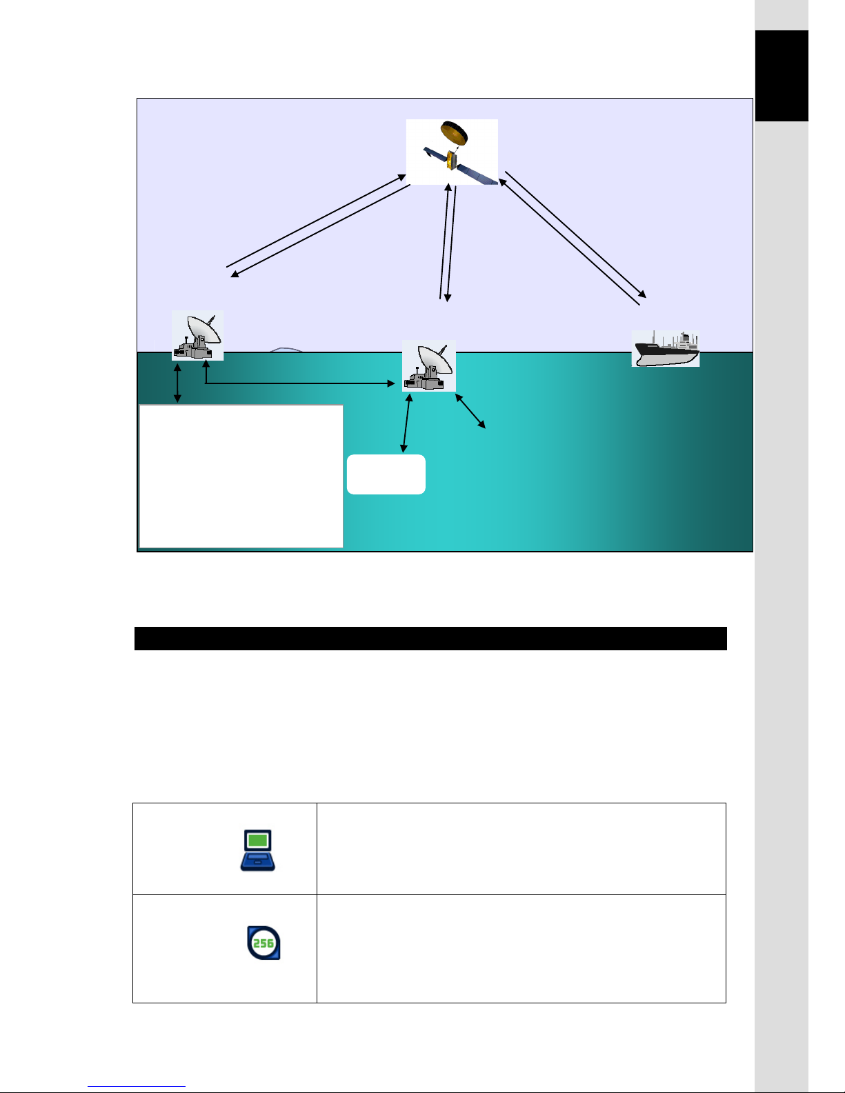
Fig.1.1.2 The Inmarsat FleetBroadband service Network
1.2 The Inmarsat FleetBroadband services
Inmarsat FleetBroadband provides service shown below.
Packet Switched service (PS), Circuit Switched service (CS), and Short Message Service (SMS)
can be used simultaneously.
JUE-501/JUE-251 supports a maximum of 11 PS connections and one CS connection at the
same time.
Packet switched service (PS)
Standard IP
• Internet and intranet access at speed up to 432kbps over a
shared channel for FB500. (Up to 284kbps for FB250.)
• Charged by data amount
Streaming IP
•
Internet
and intranet access at guaranteed data rates on
demand up to 256kbps (8, 16, 32, 64, 128 and 256kbps) for
FB500. (Up to 128kbps for FB250)
• Charged by connection time.
1) Network Coordination Station (NCS)
Inmarsat Satellite
5) Satellite Access Station (SAS)
Internet
Inmarsat headquarter
2) Network Operation Center (NOC)
3) Satellite Control Center (SCC)
4) Tracking Telemetry and
Control Center (TT&C)
International / Internal
Public network
Mobile Earth
Station (MES)
Page 28

1. Inmarsat Service systems
1-4
Circuit switched service (CS)
4kbps Voice
•
Low cost voice service equal to Inmarsat mini-M
voice
• Charged by connection time
64kbps 3.1kHz Audio
•
High quality voice service to use FAX and
analogue modem.
• Charged by connection time
ISDN UDI /RDI *
)
data
(Only for FB500)
•
ISDN 64k/56kbps data service for ISDN video
phone, etc.
• Charged by connection time
*
)
UDI = Unrestricted Digital Information
RDI = Restricted Digital Information
Short Message Service (SMS)
Short Message Service
•
Send and receive text messages up to 160 characters.
• Charged by message.
1.3 Important reminder for using JUE-501/JUE-251
NOTE
• Communication failure due to MCA wireless system interference could occur at the coast
of Japan urban area.
• 64kbps 3.1kHz Audio service is not available when satellite elevation angle (EL) value is
less than 20 degrees for the JUE-251.
• Although 8k, 16k, 32k, 64k, 128kbps Streaming IP service and CS service can be used in
the same time, use of 256kbps Streaming IP and simultaneous CS service is not possible.
• The service available to you is depending on the contract. Some of the services described
in this manual may not work for your SIM card.
• Network service is managed by Inmarsat co. or other network service providers. Network
service may be changed or terminated without prior notice due to the circumstances of the
network service providers.
Page 29

1. Inmarsat Service systems
1-5
Chapter1 The Inmarsat Service Systems
1.4 Emergency Calling
1.4.1 505 Emergency Calling
Inmarsat has introduced 505 Emergency Calling for the FBB terminals.
In a time of distress, a seafarer need only dial "505" and press either the offhook ( ) or # key-
selected for its similarity to "SOS" - to immediately contact a Maritime Rescue Co-ordination Centre
(MRCC).
Please note that 505 Emergency Calling is NOT GMDSS compliant. 505 Emergency Calling can not
be used if other phone or fax is used. Finish using phone and fax before dialing "505".
Page 30

1. Inmarsat Service systems
1-6
This page is remained as a blank.
Page 31

2. Introduction of JUE-501/JUE-251
2-1
Chapter 2 Introduction of the JUE-501/JUE-251
2. Introduction of the JUE-501/JUE-251
2.1 Outline
The JUE-501/JUE-251 Mobile Earth Station (MES) is composed of Above Deck Equipment (ADE)
and Below Deck Equipment (BDE).
The ADE consists of Antenna Assembly, Above Deck Unit and Radome, while the BDE consists of
Main Unit (MU) and Handset.
JUE-501/JUE-251 is an Inmarsat digital satellite communication terminal for voice service (4kbps
Voice), G3FAX and legacy analogue modem service (64kbps 3.1kHz Audio), (*)UDI/RDI
, maximum
432kbps(JUE-501) or 284kbps(JUE-251) Standard IP service, 8kbps, 16kbps, 32kbps,64kbps, 128kbps
and (*)256kbps
Streaming IP service and Short Message Service (SMS).
[(*) is available only for JUE-501.]
JUE-501/JUE-251 is shipped with strict quality control and inspection to provide the high quality for
consumers. JRC would like to believe you to make long use of the terminal with your satisfaction.
Network service is managed by Inmarsat co. or other network service providers. Network service may
be changed or terminated without prior notice due to the circumstances of the network service
providers.
If your JUE-501/JUE-251 has trouble or problem in your operation, please contact the dealer or agent
you purchased from.
Page 32

2. Introduction of JUE-501/JUE-251
2-2
2.2 Features
Meeting the latest FleetBroadband SDM
The JUE-501 meets the latest Inmarsat FleetBroadband FB500 technical requirements (SDM) and
JUE-251 also meets the latest Inmarsat FleetBroadband FB250 technical requirements (SDM). They
are suitable solutions for satellite communications equipment for any type of vessel, navigating the
world’s oceans.
High quality and low communication cost
The JUE-501/JUE-251 provides following services using Broadband Global Area Network (BGAN)
offered from Inmarsat.
-Low cost global voice service: 4kbps Voice
-G3FAX and legacy analogue modem service using 64kbps 3.1kHz Audio service
( unavailable for
the JUE-251 when satellite elevation angle (EL) value is less than 20 degrees)
-Standard IP service at speed up to 432kbps over a shared channel
(Up to 284kbps for JUE-251)
-Streaming IP service (8k, 16k, 32k, 64k, 128k, and 256kbps) (Up to 128kbps for JUE-251)
-UDI/RDI service (unavailable for JUE-251)
-SMS (maximum number of characters are 160)
* The service available to you is depending on the contract.
Stylish, Light weight, Space-saving, and Gyro-less
The JUE-501/JUE-251 can be installed on vessels of all sizes due to the compact and lightweight
design of the ADE. The adoption of an active and Gyro-less antenna structure makes this unit a
perfect fit for small vessels.
With the use of a single coaxial cable as the control line between the ADE and BDE the installation of
the JUE-501/JUE-251 is simple and easy.
The Rewindless antenna produces uninterrupted communication during course change.
Adaptive to various networks
The JUE-501/JUE-251 has multiple Interfaces including Ethernet, ISDN, 2TEL ports (maximum 6 TEL
ports)*, and Handset as standard equipment. An output port for WRF (Wide-band Radio Frequency)
is also provided.
*Standard equipment provides 2 telephones, and 4 more telephones can be connected when
connecting Junction Board (JB), as optional equipment.
Self-diagnosis system
The built-in self-diagnosis system continually monitors the status of the JUE-501/JUE-251 and
indicates the warnings if any errors are detected.
Page 33

2. Introduction of JUE-501/JUE-251
2-3
Chapter 2 Introduction of the JUE-501/JUE-251
2.3 Cable connection diagram and components List
2.3.1 Cable connection diagram
INMARSAT FB500 JUE-501
Interconnection Diagram
*: YARD SUPPLY
GSC-512
WRF
21-31V DC
J901
ABOVE DECK
EQUIPMENT (ADE)
CFQ-3922A
W1: Coaxial Cable
(JRC SUPPLY)
Earth Plate
(Attachment)
Earth Cable
7ZCSC0266
GYRO IF
Power Supply Unit
NBD-904
+
-
DC24V
OUT
E
AC IN
U V
0.6/1kV DPYC-2.5
*
RX_A
7ZCSC0244
Signal Cable 3m
(Attached to GYRO I/F BOX)
TB3
(to BDE)
RD1
RD2
SD1
SD2
NM-
GND
12345
6
TB11
(GYRO)
250V MPYC-7
250V MPYC-4
123
4
123
4
S1S2S3
COM
R1
S1S2S3
R2
STEP SYNC
SYNCHRO
SIGNAL
STEP
SIGNAL
5
123
BLK
WHT
TB1
(POWER)
+24V
GND
FG
RED Power Cable 5m
(Attached to
GYRO I/F BOX)
GYRO I/F BOX
NQA-2066A
RED
BRN
ORN
YEL
BLU
ORN
YEL
BRN
RED
BLU
RED
BLK
WHT
a
NMEA GYRO
(4.8K/38.4K bps,
THS, HDT, VHW)
250V TTYCS-1
*
250V TTYCS-1
*
External GPS
(4.8K/38.4K bps, GGA/ZDA/GSA)
BLK
RED
ADE
7ZCSC0222B 5m
Power Supply Cable
(JRC SUPPLY)
RED
BLK
GRN
TEL1
(Attached with Handset)
TEL2
ISDN
Handset
1m
HANDSET
NQW-267
(Attached to FAX)
FAX Power Cable
a) 2.4m, b) 1.7m
FACSIMILE
0.6/1kV DPYC-2.5
*
*1
Ship's Power
AC100/220V
EMC FILTER
TRANSFORMER
or
Ship's Power
AC100/220V
250V
TTYCS-1
*
Modular Cable
3m
(JRC SUPPLY)
(Attached to TEL)
[*1]
Ship's power AC220V :
Ship's power AC110/115V :
Ship's power AC100V :
TRANSFORMER (DD-118564)
TRANSFORMER (DD-118525)
EMC FILTER (RSHN-2003)
a) FAX-2820
b) FAX-2840
NQW-132B
TEL(1st)
TEL Cable 5m
*
*
0.6/1kV DPYC-1.5 or
[SMA J]
[RJ-11]
[RJ-11]
[RJ-45]
(Attachment)
7ZCSC0212
Coaxial Cable 0.5m
(JRC SUPPLY)
FAX Cable
a) 3m, b) 1.5m
a) (JRC SUPPLY)
b) (Attached to FAX)
(ChartCo SUPPLY)
ChartCo
Receiver
TA
ETH1
[RJ-45]
ETH4
ETH3
ETH2
[RJ-45]
[RJ-45]
[RJ-45]
EXT WAN
JRC LAN
[RJ-45]
[RJ-45]
VDB1
GSC-511
TIP3
RING3
FG
TEL3
TIP4
RING4
FG
TEL4
TIP5
RING5
FG
TEL5
TIP6
RING6
FG
TEL6
RX_B
TX_A
TX_B
GND
OP1
OP1D1
OP1D2
12V
GND
FG
OP2
OP2D1
OP2D2
12V
GND
FG
VOUT
NC
I/02
NO
COM
ACK
12345
6
a
RED
BLK
BLK1
RED1
BLK2
RED2
BLK3
RED3
250V
TTYCS-4
*
PC/HUB
PC/HUB
PC/HUB
JRC LAN
(RMS)
Cat-5 LAN Cable
*
*
*
*
EXT WAN
(another sat-com)
*
Voice Distress
Button
NQE-3301
231
456
BLK1
RED1
BLK2
RED2
BLK3
RED3
RED
BLK
L2
L1
RED
BLK
L2
L1
TEL JB
NQE-3058C
TEL JB
NQE-3058C
CQD-2243
MAIN UNIT JB
2625242322212019181716151413121110
9876543
2
1
J2
J3
RMT1
Remote
Power
Control
RMT2
GND
VOUT
NC
I/01
NO
COM
ACK
GPS_A
GPS_B
FG
GPS IN
BUZZ
SYNC
VDB2
RX_B
RX_A
12V
GND
GND
242322212019181716151413121110
987654321
1
2
250V MPYC-2
*
Remote
Power Switch
Cat-5 LAN Cable
Cat-5 LAN Cable
Cat-5 LAN Cable
Cat-5 LAN Cable
(YARD SUPPLY)
Earth Plate
RED1
BLK1
RED2
BLK2
*
250V
TTYCS-1Q
250V TTYCS-1Q
RED1
BLK1
RED2
BLK2
RED1
BLK1
RED2
BLK2
D1
G
TB1
EXT BUZ
G
NCE-6824A
D2
12V
GND
TB2
D1
D2
12V
GND
TB3
TB4
*
RED1
BLK1
RED2
BLK2
D1
G
TB1
EXT BUZ
G
NCE-6824A
D2
12V
GND
TB2
D1
D2
12V
GND
TB3
TB4
RED
BLK
250V TTYCS-1
*
(Attached to TEL)
RED
BLK
L2
L1
TEL JB/NQE-3058C
NQW-132B
TEL(3rd)
TEL Cable 5m
250V TTYCS-1RED
BLK
*
(Attached to TEL)
NQW-132B
TEL(4th)
TEL Cable 5m
RED
BLK
L2
L1
TEL JB/NQE-3058C
NQW-132B
TEL(5th)
RED
BLK
250V TTYCS-1
*
(Attached to TEL)
TEL Cable 5m
RED
BLK
L2
L1
TEL JB/NQE-3058C
NQW-132B
TEL(6th)
250V TTYCS-1
RED
BLK
*
(Attached to TEL)
TEL Cable 5m
RED
BLK
L2
L1
TEL JB/NQE-3058C
RED1
BLK1
RED2
BLK2
250V
TTYCS-1Q
*
250V TTYCS-1Q
RED1
BLK1
RED2
BLK2
RED1
BLK1
RED2
BLK2
D1
G
TB1
EXT BUZ
G
NCE-6824A
D2
12V
GND
TB2
D1
D2
12V
GND
TB3
TB4
*
RED1
BLK1
RED2
BLK2
D1
G
TB1
EXT BUZ
G
D2
12V
GND
TB2
D1
D2
12V
GND
TB3
TB4
NCE-6824A
LAN Cable 5m
PC
(JRC SUPPLY)
(OWNER SUPPLY)
Voice
Distress
Button
NQE-3301
(JRC SUPPLY)
MVVS-20/0.18x6-
8.5P-(8) 5m
YEL
GRN
RED
BLK
WHT
BRN
1.SYNC(BRN)
◆
◆
: Pin No.
2.BUZZ(WHT)
3. RXA(YEL)
4.RXB(GEN)
5.+12V(RED)
6.GND(BLK)
23478
9
TB1
EMC filter is only for FAX-2820
Fig. 2.3.1 Cable connection diagram (JUE-501)
Page 34

2. Introduction of JUE-501/JUE-251
2-4
2.3.2 Components list
Table 2.3.2 Components list
Name of equipment Typ e Q’ty
Standard
Components
ADE
JUE-501 GSC-511 1
JUE-251 GSC-251 1
BDE
JUE-501 GSC-512 1
JUE-251 GSC-252 1
Handset NQW-267 1
PSU cable
(between EXT PSU and BDE main unit)
7ZCSC0222B 1
Instruction Manual 7ZPSC0427 1
Installation Manual 7ZPSC0429 1
Quick Reference Guide 7ZPSC0431 1
CD-ROM 7ZPSC0433 1
S
upplied parts for
ADE installation
JUE-501 MPXP34916 1
JUE-251 MPXP34915 1
Supplied parts for BDE installation 7ZXSC2502 1
Spare fuse for BDE 7ZXSC0008 3
Inspection result 1
Option
Coaxial cable
(between ADE and BDE)
JUE-501 CFQ-3922A5* (50m) 1
JUE-251 CFQ-5924A3** (30m) 1
Relay cable (between CFQ-3922A/3923A
and BDE main unit)
7ZCSC0212 1
Relay connector
(In case of connecting
CFQ-3922A/3923A cable to JUE-251 ADE)
NJ-TNCP
(JRC : 5JAAE01753)
1
Junction Board CQD-2243 1
Telephone NQW-132B 1
Facsimile (brother FAX-2820)
7EZSC0060
1
Facsimile (brother FAX-2840)
5HPCD00003
1
Power transformer for Facsimile
(For AC100V)
DD-118525 1
Power transformer for Facsimile
(For AC110V/115V)
DD-118564 1
EMC Filter for facsimile
(For AC230V direct coupling)
RSHN-2003
(for FAX-2820)
1
External Power supply Unit (EXT PSU) NBD-904 1
Telephone Junction Box (TEL JB) NQE-3058C 2
Handset extension cable 7ZCSC0291 1
GYRO I/F Box NQA-2066A*** 1
Page 35

2. Introduction of JUE-501/JUE-251
2-5
Chapter 2 Introduction of the JUE-501/JUE-251
External Buzzer NCE-6824A Max 4
Voice Distress Button NQE-3301 Max 2
Wall mount adapter for VDB 7ZZSC0095 Max 2
Instruction Manual (Japanese) 7ZPSC0428 1
Installation Manual (Japanese) 7ZPSC0430 1
Quick Reference Guide (Japanese) 7ZPSC0432 1
*CFQ-3922A series (15m to 45m, 5m interval、5D)、CFQ-3923Aseries (70m and 100m、10D)are available as options.
**CFQ-5924A15 (15m), CFQ-3922A series (35m to 50m, 5m interval, 5D) and CFQ-3923A series (70m and 100m、10D)are
available as options.
***SYNC/STEP GYRO requires GYRO I/F BOX.
Page 36

2. Introduction of JUE-501/JUE-251
2-6
2.4 Dimensional drawing (JUE-501/JUE-251 standard components)
2.4.1 ADE (Above Deck Equipment) JUE-501[GSC-511]
Fig. 2.4.1 Appearance of JUE-501 ADE (GSC-511)
Unit: mm
Mass: Approx.20kg
Page 37

2. Introduction of JUE-501/JUE-251
2-7
Chapter 2 Introduction of the JUE-501/JUE-251
2.4.2 ADE (Above Deck Equipment) JUE-251[GSC-251]
Fig. 2.4.2 Appearance of JUE-251 ADE (GSC-251)
Unit: mm
Mass: Approx.4.7kg
Page 38

2. Introduction of JUE-501/JUE-251
2-8
2.4.3 BDE (Below Deck Equipment) JUE-501[GSC-512]
Fig. 2.4.3 Appearance of JUE-501 BDE (GSC-512)
Unit: mm
Mass: approx. 4.5kg
Page 39

2. Introduction of JUE-501/JUE-251
2-9
Chapter 2 Introduction of the JUE-501/JUE-251
2.4.4 BDE (Below Deck Equipment) JUE-251[GSC-252]
Fig. 2.4.4 Appearance of JUE-251 BDE (GSC-252)
Unit: mm
Mass: approx. 4.5kg
Page 40

2. Introduction of JUE-501/JUE-251
2-10
2.4.5 Handset [NQW-267]
t
4-Mounting holes
Fig. 2.4.5 Handset
Unit: mm
Mass. approx. 0.5kg
Page 41

2. Introduction of JUE-501/JUE-251
2-11
Chapter 2 Introduction of the JUE-501/JUE-251
2.4.6 Junction Board [CQD-2243]
Intentionally Blank.
Fig.k2.4.6 Junction Board
Fig. 2.4.6 Appearance of Junction Board (CQD-2243)
Unit: mm
Mass: approx. 2.5 kg
Page 42

2. Introduction of JUE-501/JUE-251
2-12
2.4.7 Coaxial cable [CFQ-3922A5/CFQ-5924A3]
Typ e Length
Connector
Dia.
Cable
Dia.
Mass
Minimum
bending radius
Remarks
CFQ-3922A5 50m±0.5m 30mm 15mm 12.5kg or less 100mm
Standard for JUE-501
With N connector
CFQ-5924A3 30m±1.0m 22mm 8mm 2.5kg or less 50mm
Standard for JUE-251
With TNC connector
Concerning cable length option, please refer to [Tabl e 2.3.2 Components list].
Fig. 2.4.7 Coaxial cable
mm
mm
Standard cable for
JUE-501
Mass:12.5kg
Standard cable for
JUE-251
Mass:2.5kg
CFQ-5924A3
CFQ-3922A5
Page 43

3. Appearance
3-1
Chapter 3 Appearance
3. Appearance
In this section, the composition of the JUE-501/JUE-251 and terminal equipments are explained.
1) Above Deck Equipment (ADE): Antenna unit and radome (Antenna Cover)
2) Blow Deck Equipment (BDE): Main unit
3) Coaxial cable: A Cable connects ADE to BDE
4) Handset: Handset and cradle
5) Terminal equipments: Accessories used for communication (user supplied PC, FAX, and
telephone)
3.1 ADE
Radome covers the antenna equipments, which is composed of:
a) Low Noise Amplifier (LNA)
b) Above Deck Unit (ADU) contains GPS circuit.
c) Rotary joint
d) Antenna pedestal
All signals (and power) pass through a single coaxial cable, which connects the ADE and BDE.
Fig. 3.1 ADE
GSC-511 for JUE-501
GSC-251 for JUE-251
Page 44

3. Appearance
3-2
3.2 BDE
Main unit
Main unit appearance
Fig. 3.2a Main unit appearance
Fig 3.2b Main unit front view
Front view
Front view
Rear view
1. Power Switch
3. LEDs
2. SIM Card slot
4. Handset port
Page 45

3. Appearance
3-3
Chapter 3 Appearance
1 Power Switch
Turns power on and off.
2 SIM card slot
Mounts a SIM card.
3 LEDs
Indicates the communication/apparatus status. READY LED, ALARM LED and COMM LED lit in
the same way as LEDs on the Handset, except at the time of startup. Main unit has two more LEDs
(ANT. LED and SMS LED) on its front panel and indicates antenna status and new-SMS-receiving
status. The meanings and sequence of the LEDs are described in [Appendix P Front Panel LED lamps].
4 Handset port (12-PIN Modular Cable)
Connects with Handset unit.
Offered service: 4kbps Voice and SMS
5 TEL 1/2 ports (RJ-11 type 6-PIN Modular Cable)
Connects the analog equipment, terminal telephones, and facsimile to the main unit.
Offered services: 4kbps Voice and 64kbps 3.1kHz Audio
6 Antenna cable connector
Connects with the coaxial cable from the antenna (ADE).
7 ISDN port (RJ-45 type 8-PIN Modular Cable for ISDN)
Connects with equipment, which has an ISDN interface.
Offered services: 4kbps Voice, 64kbps 3.1kHz Audio, UDI, and RDI
Rear view
Fig. 3.2c Main unit rear view
7. ISDN Port
11. User LAN port
15. Earth
8. WRF connector
10. JRC LAN port
5. TEL1/2 port
6. Antenna cable
connector
14. DC Power connector
12. FUSE
9. Ext WAN port
13. VDB port
Page 46

3. Appearance
3-4
8 WRF connector
Connects with Wide-band Radio Frequency (WRF) communication equipment such as Chartco etc.
9 Ext WAN port (RJ-45 type 8-PIN Modular Cable for Ethernet)
Connects with External WAN such as ESV.
10 JRC LAN port (RJ-45 type 8-PIN Modular Cable for Ethernet)
Connects with JRC LAN. It creates additional value like remote maintenance or status monitor by
connecting JRC products other than FBB.
11 User LAN port × 4 (RJ-45 type 8-PIN Modular Cable for Ethernet)
Connects with user device such as user PC.
Offered services: Standard IP, Streaming IP, and SMS.
A maximum total capacity of 32 W PoE ( Power over Ethernet ) is available on User LAN.
12 Fuse
Melt down when over current are detected.
Replacement procedure: Loosen the folder head to counterclockwise direction with slotted
screwdriver, and pull out the folder when it is ejected. Replace the fuse to new one and set it in the
folder. Insert the folder and tighten it clockwise direction until folder is securely locked in place.
13 VDB port
Connects with Voice Distress Button (VDB).
14 DC power connector
Connects with the cable which supplies the power source to the main unit.
15 Earth
PoE LED:
Lit in green when power is supplied.
Lit in orange when PoE is failed.
(power supplying beyond 32 W)
Link LED:
Bright when the link with the
connected terminal has been
established. (It shines in orange for
10Base-T and it shines in green for
100Base-T.)
Page 47

3. Appearance
3-5
Chapter 3 Appearance
Fig. 3.3 ADE-BDE connecting cable
3.3 ADE - BDE connecting cable
*This cable can be connected to ADE and BDE in either direction.
50m (standard) for JUE-501
30m (standard) for JUE-251
Page 48

3. Appearance
3-6
3.4 Handset
The Handset consists of main body and cradle (Handset rest)
The Handset is fixed on the cradle by a strong magnet.
Do not mount the Handset near CRT device or other devices;
otherwise performance of the
devices may be affected by the Handset’s magnetic field.
Fig 3.4a Handset and cradle
Handset operation side consists of three sections:
3.4.1. LCD / LED section
LCD screen displays JUE-501/JUE-251 user
information.
LEDs indicate communication/apparatus status.
3.4.2. Functional button section
Buttons in this section control basic functions of the
JUE-501/JUE-251.
3.4. 3. Alpha-Numeric button section
Numeric mode is used to enter number sequences like
phone numbers. Alpha mode is used to enter letters.
These two modes are switched by pressing Aa
button of the Function section.
Fig. 3.4b Section of Handset
Handset fixed on cradle
Front view
(Operation side)
Cradle
Inside view
(Receiver side)
LCD/LED
section
Functional
button section
Alpha-numeric
button section
CAUTION
Page 49

3. Appearance
3-7
Chapter 3 Appearance
3.4.1 LCD/LED section
Functions of the LCD screens of the Handset.
Common items for all screens are:
1 [Operational button] Displays operatable keys: , or
2 [Enter mode] Displays which key enter mode is accepted, Aa (alphabet mode), or nothing
(numeric mode) is displayed. (Only in SMS editing mode, aA is displayed)
Displays every status: , expect for Enter mode
3 [Each status] Displays every status : , , , , , or
4 [Condition of reception] Displays style icon
5 [Connecting IP service] Displays style icon
6 [Selected satellite] Displays E143.5 etc.
7 [Current time] Displays UTC/LT, or communicating time.
8 [Status of equipment] Displays CS PS READY, COMM (OUT), etc.
Fig. 3.4.1a Explanation of LCD section
Fig. 3.4.1b LCD section
12-digit
4 lines
Aa
APAC E143.5
10:55 UTC
CS PS READY
8
6
7
1 2 3 4 5
R
R
Page 50

3. Appearance
3-8
Table 3.4.1 Explanation of items displayed on screens
Displayed items Contents
1 Operational button
Displays when the scrolling-up/down or switching-left/right is available.
Scroll the screen when up/down is displayed, with buttons.
Switch the screen when left/right is displayed, with buttons.
2 Input mode
1) Displays Aa or aA mark when alphabet input mode.
2) Displays when FAX is out of service.
3) Displayes when the incoming call is not answered
These Aa and aA icons are :
• Displaying the terminal is in the alphabet input mode. If these icons are not
displayed, numeric input mode only available.
(Except in SMS menu, aA is displayed as lower case letter mode and
Aa is displayed as upper case letter mode.)
This icon is :
• Displaying FAX is out of service. This icon is displayed when satellite elevation
angle (EL) value of JUE-251 is less than 20 degrees.
3 Each status
1) Displays when Phonebook menu is selecting.
2) Displays when Outgoing Calls List menu is selecting.
3) Displays when Incoming Calls List menu is selecting.
4) Displays when call is on hold.
5) Displays when SMS message is arrived.
6) Displays when the storage volume of SMS message is FULL.
This icon is :
• Displaying the storage volume on SIM card for SMS message is full. To send
and receive new message, please delete unnecessary messages.
This icon is :
• Not displayed even new message is received, when another icons ( , ,
, and ) are need to be displayed in this area.
• Disappeared when Inbox menu (refer to [8.2.2 Inbox menu](p8-15)) is selected
and [Inbox list view screen] is once opened, regardless of the newly arrived
message is read or not.
• Disappeared when Power OFF with displaying it, and ON afterwards.
• Kept displaying even the new message is read, when it is executed by an
external access such as PC.
R
R
R
R
Page 51

3. Appearance
3-9
Chapter 3 Appearance
4 Condition of
reception
1)Displays a bar graph of signal reception level by seven (7) grades. It blinks
when antenna was hidden from satellite by obstructions.
Number of bars
Communication
0 Impossible (no reception)
1 Possible to communicate but unstable
2 Possible to communicate but unstable
3
Possible to communicate stably
4 Possible to communicate stably
5 Possible to communicate stably
6 Possible to communicate stably
5 Connecting IP
service
1)Displays an icon which shows connecting IP service .
Icon style IP service type
Standard IP service only.
Streaming IP service only.
Both of above IP services.
6 Selected
Satellite
Displays selected satellite /communicating terminals.
• Satellite (Displays when CS communication is not used)
It displayed in units of 0.1 degree, and in the range of W180.0 to
E180.0
7 Current time
Display is changed between UTC (Universal Time coordinated) and LT (Local Time).
If you set the time difference, the display is switched to LT automatically.
Refer to [7.9.1.2 Local Time setting](p7-38).
Page 52

3. Appearance
3-10
8 Status of equipment
Displays the status of equipment. Normally, this area displays
below contents under waiting communication or under transmitting.
Status of
equipment
Displayed txt. Contents
Normal nnn/NNN
Displays the used amount (nnn) and total
capacity (NNN) of input characters of SMS
Abnormal ADE? ADE is abnormal condition
Abnormal SIM? SIM is abnormal condition
Normal SIM LOCK
The availabl
e SIM is limited by Facility
Lock function (Sec. 6.5.7), and the terminal
is locked.
Abnormal POSITION?
GPS does not receive the radio wave from
satellite. It is not always failure.
The other factors including blocking can be
considered.
Normal HEADING?
GYRO of Sync/Step requires Heading value
Abnormal GYRO?
GYRO is abnormal condition.
Normal COMM (OUT)
Called from the ship.
Normal COMM (IN)
Called from the land.
Normal SAT SEARCH
Searching Satellite.
Normal REGISTERING
It is displayed from the Satellite search is
completed and until
READY status is
started.
Abnormal SEARCH NG
Satellite search has been failed.
Normal CS PS READY
Communication is possible.
(Circuit switch service and Packet switch
service are available)
Normal CS READY
Communication is possible.
(Circuit switch service only available)
Normal PS READY
Communication is possible.
(Packet switch service only available)
Normal NOT READY
Communication is impossible.
The items in this
table are arranged in
displaying priority.
Displayed only in
SMS menu
Page 53

3. Appearance
3-11
Chapter 3 Appearance
Fig. 3.4.1c Indication of LEDs
Lighting of LEDs
LEDs on the Handset are lit in the same way as the main unit, except just after the startup.
READY ALARM COMM
Ready lamp: displays communication status
(available/non-available)
Green light:
All communication services are
available.
Blinking Green: No service is available
(starting system, calibrating cable, searching
satellite or registering SIM).
Orange light: Registration failure or SIM card
is not inserted.
Blinking Orange:
・ Starting system with initialization.
・ After power switch is turned off, until the
power is run out completely.
(No light: power switch is OFF)
ALARM lamp: indicates failure alert
Red light: Failure has occurred in the system.
(No light: The status is normal)
COMM lamp: indicates communication starting.
Green light: In CS service communication
(No light: In PS service communication,
or no CS service communication is on the way
now.)
Page 54

3. Appearance
3-12
Fig. 3.4.2 Functional button
section
Fig. 3.4.3
Alpha-numeric button section
3.4.2 Functional button section
This section describes function buttons except those for entering characters.
Buttons and its function
GH
3.4.3 Alpha-numeric button section
Buttons and usage
Enters # and also scrolls the screen to the right direction.
Enters* and also scrolls the screen to the left direction.
Enters numerical/alphabetical
characters and symbols.
Aa
ST ATU S
W
0.,-
Switching button Switches enter mode, between alphabets and numbers.
SMS button Reads, creates, sends, and deletes Short Message Service(SMS).
Status button Makes direct access to STATUS menu.
OK
OK button Registers entered contents.
Scroll up button
Scrolls up the screen / makes direct access to Outgoing Calls List menu.
MENU
Menu button Makes direct access to TOP Menu.
Satellite button Makes direct access to Satellite menu.
Phonebook button Makes direct access to Phonebook menu.
CLR
Off Hook(Call starting)button Makes a call and receives a call.
Clear button Clears (cancels) the entry immediately before.
On Hook(Call finishing)button Hangs up the call.
Scroll down button
Scrolls down the screen/makes direct access to Incomming Calls List menu.
6MNO
#
3DEF
3DEF
W
9XYZ
2ABC
8TUV
5JKL
0.,-
1
P
7QRS
4GHI
This button has no function.
This button adjusts the
voice volume and the
screen brightness
of the
Handset.
SMS
FN button.
This button is used for call
waiting and call holding.
Page 55

3. Appearance
3-13
Chapter 3 Appearance
3.5 Communication terminals
3.5.1 Terminal requirements
*Series connection (of terminal telephone and FAX) is not available on one port.
Fig. 3.5.1 Terminal requirements
RJ-11
TEL
cable
RJ-11
TEL
cable
* When five or more devices are connected to Ethernet
Port
TEL2 /TEL1 Port
RJ-45
Ethernet
cable
NOTE
JUE-501/JUE-251 recognizes the type of Ethernet
cable (cross or straight) automatically.
A maximum of total 32W PoE (Power over
Ethernet) is available on User LAN.
RJ-45
ISDN
cable
Terminal
Adapter
NOTE
Service type of TEL1/2 port must be set properly
according to the connected terminal (telephone or
FAX).
(Refer to p4-12 for Service type modification).
RJ-45
HUB
Ethernet
cable
Ethernet
cable
RJ-45
Ethernet
cable
RJ-45
Ethernet
cable
E xt WA N
Port
JRC LAN
Port
User LAN
Port
Handset
ESV
etc
VDR
ISDN
Port
Page 56

3. Appearance
3-14
3.5.2 Usage environment
Table 3.5.2 Usage environment
PC
OS
Microsoft Windows XP/ Vista/ 7
Interface
Ethernet
ISDN Terminal
Equipment
Switch type
Euro ISDN, INS
Coding type of voice
A-law, μ-law
Interface
RJ-45 (S/T interface)
3.6 Handset menu
On the JUE-501/JUE-251, various menu screens can be displayed and set, from Handset.
Guest User
*1)
cannot utilize the menus of Admin User
*2)
.
*1)
Guest User: General user
*2)
Admin User:User who is authorized to make settings of the JUE-501/JUE-251.
Handset menu
For more detail, refer to [7. Handset Menu System](p7-1).
Displays JUE-501/JUE-251 status and of communication status(For all user)
Changes JUE-501/JUE-251 status and communication status (For Admin user only)
Fig. 3.6 Handset menus (Classified by user authority)
Redial
(Displays Redial
number list and makes a
call with it)
Status
(Displays internal status
for carry out
communication)
Internal
(Make an internal call)
Alarmpack
(Displays detailed
Information of JUE-501/
251 and Alarm history)
Satellite
(Selects satellite, and
displays spot beam No.)
Phonebook
(Registers Speed Dial
Number to the Handset and
terminal telephone)
Port
(Setup each port)
Terminal
(Setups the basic
operation of BDE)
Admin
(Displays menu list for
the ADMIN user)
User Cont.
(Registers users and
restricts them)
Auto Dcn.
(Sets automatic
disconnection of
communication)
Telephony
(Setup the telephony
including auto answer and
supplementary service)
SIM menu
(Sets SIM card-use
operation)
SMS
(Reads/creates/sends/
deletes SMS)
Default
(Resets to the factory
default)
Call Log
(Displays Call logging
history)
Page 57

4-1
Chapter4 Getting Started
4. Getting started
4. Getting started
In Section 4.1, connecting the Handset and terminal devices to Main unit, and installing SIM card
are described; and initial setting for communication is described in Section 4.2.
NOTE
JUE-501/JUE-251 has two types of satellite tracking mode, Signal tracking mode and Gyro tracking
mode.
Press MENU+3 button (Satellite menu) on the Handset. [3.Heading
] is displayed when the
JUE-501/JUE-251 is set as Gyro tracking mode.
You can use Web browser or LaunchPad for the Packet switching service (Standard/Streaming IP
communication).
About Web browser
JUE-501/JUE-251 is accessible by Web browser on your PC. Functional adjustment of
JUE-501/JUE-251 as well as fundamental services like displaying the status/setting of
JUE-501/JUE-251, connecting/disconnecting Standard/Streaming IP service, and
sending/receiving SMS can be made by Web browser.
About the LaunchPad
LaunchPad is the application software manufactured by Inmarsat for handling Mobile Earth
Station (MES). Fundamental services are also available by using LaunchPad.
About the TCP accelerator (TCP PEP)
TCP accelerator (TCP PEP) is PC application software which improves the performance of TCP
applications (transfer rate) over FleetBroadband network.
Install TCP accelerator (TCP PEP) to your PC using attached CD-ROM if necessary.
NOTE
• Refer to [Chapter 6 Web Menu System](p6-1) of this manual to control BDE by Web browser.
• JUE-501/JUE-251 supports Microsoft Internet Explorer 7, Mozilla Firefox
3.6 and their later
version.
NOTE
•
Refer to [Appendix K] and [Appendix L] of this manual to install and to use the LaunchPad.
• LaunchPad
version 5.0.4 or later supports the Windows XP/Vista/7 32bit.
NOTE
• If using TCP accelerator
is not made by Inmarsat, or depending on the type of application,
transfer rate may not be improved.
• The TCP accelerator version2 or later supports the Windows XP/Vista/7 32bit and Windows 7
64bit.
Page 58

4-2
4. Getting started
TEL
FAX
PC(s) connected
with Ethernet port
Terminal
Adapter
Handset
Ext WAN
VDR
4.1 Connecting terminals and power on
4.1.1 Connecting terminals with cables
(Connection is
depending on the
Terminal Adaptor)
NOTE
• The JUE-501/251 recognizes Ethernet cable type (cross or straight) automatically.
• Service type of TEL1/2 port must be set properly according to the connected terminal
(telephone or FAX). (Refer to p4-12 for Service type modification).
• A maximum of total 32W PoE (Power over Ethernet) is available on User LAN.
Fig.4.1.1 The Cable connection of each terminal
Page 59

4-3
Chapter4 Getting Started
4. Getting started
Connecting terminal telephone and FAX to TEL1/2port
Connect terminal telephone/FAX to TEL1 and TEL2 port with 2 wire, 6-PIN modular cable (RJ-11
type).
Connecting Handset to Handset port
Connect adapter of Handset to Handset port.(12-PIN modular cable)
Connecting PC to User LAN port
Connect your PC to User LAN port with Ethernet cable.
Connecting VDR to JRC LAN port
Connect VDR (produced by JRC) to JRC LAN port with Ethernet cable if needed.
Connecting external WAN to Ext WAN port
Connect external WAN to Ext WAN port with Ethernet cable if needed.
Connecting terminal adapter to ISDN port
Connect terminal adapter to ISDN port with ISDN cable.
(Subsequent connection depends on the type of terminal adapter)
Page 60

4-4
4. Getting started
4.1.2 Setting/removing SIM card
Please make sure that SIM card is inserted correctly before turning on the power every time.
Do not set/remove the SIM card during power switch is turned on.
SIM card setting procedure (Before power switch is turned on)
1)
Remove the SIM card protector by unscrewing cross-head screws on front
panel.
2) Insert your SIM card with the metal side down. Push it in until you
hear the SIM card slot make a click sound.
3) Fasten the SIM card by sliding the black knob.
4) Restore the SIM card protector by driving the screws in.
NOTE
・ JUE-501/JUE-251 will not work without a valid SIM
card, which is furnished from the
Distribution Partner.
・ Make sure that power switch is correctly turned off, before you set/remove the SIM card
to/from main unit.
CAUTION
Page 61

4-5
Chapter4 Getting Started
4. Getting started
SIM card removing procedure (After power is turned off)
1) Remove the SIM card protector by unscrewing cross-head screws on front panel.
2) Loosen the SIM card by sliding the black knob.
3) Push the SIM card and then it comes out. Remove the SIM card.
4) Restore the SIM card protector by driving the screws in.
Page 62

4-6
4. Getting started
4.1.3 Power ON
Before turning on the power, check the following;
• Check the obstacles between antenna and satellite.
• Check that SIM card is correctly set.
• Check that the breaker of inboard power supply is turned on.
• Check that the coaxial cable from ADE is connected to BDE, certainly.
• Check that the Handset is connected to BDE, certainly.
Power ON
Turn the “POWER” switch of the main unit to “ON”.
The READY LED on the front panel will light up in green and start blinking. After a while, the
ANTENNA lamp will start blinking and then both lamps will stop blinking and light green.
Although there is nothing wrong with JUE-501/JUE-251, turning on the switch makes some noise
on ADE.
Power OFF
Turn the “POWER” switch to “OFF”.
Then, the READY lamp begins blinking in orange color, while the power source disconnecting
process is carried out. After, the power source disconnecting process is completed, the power
supply is turned off.
Do not remove the power supply cable before the power source disconnecting process is
completed.
Fig.4.1.3a Power switch and LEDs of Main unit
Power Switch
CAUTION
LEDs
Page 63

4-7
Chapter4 Getting Started
4. Getting started
Satellite Search (acquisition) function works automatically
When JUE-501/JUE-251 is turned on, the system automatically calculates the satellite position by
measuring ship's position by GPS (built-in), and then automatically turns the antenna towards the
satellite.
After acquiring the satellite, the JUE-501/JUE-251 automatically controls the antenna angle to
maximize receiving signal strength.
LCD screen of Handset displays “CS PS READY” when communication is available.
NOTE
If the communication fails although LCD screen shows [CS PS READY], low level of receiving
signal strength is suspected. Try the communication again after a while.
Initialization of the unit may take more than 5 minutes to complete. During this time, "CS PS
READY" may not be displayed on the screen. It is not abnormal status (the JUE-501/JUE-251 is
executing the initialization, satellite search, and registering to the network).
NOTE
Please confirm that the GPS you are using reports proper position. (Refer to [7.1.3 Position status
display],p7-6).
Contact the purchasing dealer, JRC agent or one of the JRC branches with confirming above
matter, when the satellite search function does not work.
”SEARCH NG” is displayed in status column of Handset screen, when automatic satellite search
function is failed. In this case, carry out satellite acquisition again manually after checking that
there is no obstacle between the antenna and the satellite (refer to [4.2.3. Setting satellite search])
(p4-14). If satellite search was not executed manually, JUE-501/JUE-251 will restart satellite
search automatically after 10 minutes.
Fig. 4.1.3b SEARCH NG status of Idle screen
APAC E143.5
14:03 UTC
SEARCH NG
Page 64

4-8
4. Getting started
Communication available status
APAC E143.5
14:03 UTC
CS PS READY
4.1.4 Screen display of Handset
Go to chapter 4.2 for initial
setting.
Turn on JUE-501/JUE-251 by pushing power
switch off Main unit.
If Gyro is being selected for tracking, refer to
Appendix C.3.
Initializing
Initialize
ON
[READY] lamp lit.
(Refer to [3.4.1. LCD/LED section] (p3-11).
* Antenna bars display communication status
0 : Impossible to communicate (no reception)
1 to 2:Possible to communicate but unstable
3 to 6:
Possible to stable communicate
A LED of Main unit starts blinking.
About 90 seconds later, initializing is started
and blinking [Initialize] text is displayed.
It takes about 1 minute until satellite
searching is started.
Satellite searching
[SAT SEARCH] text is displayed on the
lowest, [Status] line. Satellite search is
started.
Satellite search is terminated and then
[REGISTERING] text is displayed.
Registering to Inmarsat network is started.
APAC E143.5
14:03 UTC
SAT SEARCH
Registering to network
APAC E143.5
14:03 UTC
REGISTERING
Registering is terminated and [CS PS
READY] text is displayed.
Various services are available.
Page 65

4-9
Chapter4 Getting Started
4. Getting started
(Screen transition when power switch is turned off)
Fig.4.1.4b Screen transition when Power switch is turned off
NOTE
Carry out available countermeasure referring to [7.10.Other screen: TX alarm screen] (p7-77), when
JUE-501/JUE-251 displays the below screen during communication.
These screens indicate a failure has occurred on the communication system of the JUE-501/JUE-251.
Fig. 4.1.4c TX alarm screen
Power-off screen
Power OFF
Turn off the power switch.
Quitting operation is on the way in the
JUE-501/JUE-251. Characters on the
screen blink.
Screen and all LEDs are turned off.
Operation is completed.
TX Alarm
OK : Reset
T
OFF
Blinking
Page 66

4-10
4. Getting started
Go to Chapter8 (p8-1)
Using ISDN port
4.2 Initial setting for communication
Setting flow
Fig. 4.2a Setting flow
NOTE
Following screen pops-up for a moment and returns to previous action
/screen when wrong
operation/entering is carried out from Handset.
Fig. 4.2b Setting error screen
Error
Handset
Go to Chapter5 (p5-1)
How to use the telephone/FAX
Go to Chapter6 Web Menu System (p6-1)
Ethernet port
ISDN port
Mode setting of Guest and Admin (Chapter 4.2.1, p4-11)
GGoo ttoo SSuubbsseeccttiioonn 66..44..22 CCoonnnneecctt ttoo tth
h
ee
IInntteerrnneett ((pp66--1155)
)
Page 67

4-11
Chapter4 Getting Started
4. Getting started
4.2.1 Mode setting of Guest and Admin
Guest user can perform the daily operation of the JUE-501/JUE-251.
Admin user can access additional functions like setup of the JUE-501/JUE-251 and information control.
When power switch is pressed only, the user logs in as a Guest user.
To operate the Admin user-limited menu described [5.1.5 Adjusting Handset], [6.5 Menus for Admin
Users (Web)] or [7.9Admin menu (Handset)] of this Manual, Log-in with secret code of Admin user is
required.
Fig. 4.2.1 Mode setting of Guest/Admin user
NOTE
* Return to Idle screen by pressing CLR button several times or pressing (On-hook) button
once to quit Admin user mode.
!
Error
Error screen
APAC E143.5
14:03 UTC
READY
1 Status
2 SMS
READY
8 Alarmpack
9 Admin
READY
Secret Code?
OCEAN
Secret Code?
****
READY
1 Terminal
2 Telephony
Admin menu screen
This screen is displayed soon, when the secret code
is authenticated.
You have free access to Admin menu after this
screen is displayed.
Idle screen
Press MENU button, then TOP menu opens.
Secret code setting screen
Enter 4-digit Secret code. The entered characters are
hidden by ****.
TOP menu screen
Press button to move the cursor, and select [9 Admin].
Then press OK button.
Error screen
This message is displayed soon after the secret code is entered wrongly,
and the screen returns to Top menu.
NOTE
Initial secret code of Admin is “0001”.
Page 68

4-12
4. Getting started
4.2.2 Setting outgoing service type
In this section, setting the outgoing service types for TEL ports and ISDN port is explained.
The service type set here is used as the default for making a call on the port. Select the outgoing service
type for each port by following the terminal device (telephone or FAX) being connected to each port.
Open [9 Admin] menu by the sequence of [4.2.1] screen. Select [2 Telephony] menu, then
[
Telephony menu] screen will open. Select [1 Telephony], and open [Telephony setting item
selection] screen.
Select the port you want to set from [TEL1] ~ [TEL6] or [ISDN] and open [TEL
menu] (or [ISDN menu]) screen. Then, select [3 Out Type] and choose outgoing service type from
[Voice], [Fax] and [Audio]. Press OK button and the screen returns to [TEL menu] (or [ISDN menu] )
screen. The contents of each service type are explained below.
Regardless of setting here, Voice call can be made by adding * on the head of dialing sequence, and
Fax/Audio call can be made by add ** on the head of dialing sequence. Refer to [5.2.1 Dial-up
procedure for forced setting of service type](p5-30).
Service type setting screen
Select [Vo i ce ] / [Fax] / [Audio]
and press OK button.
TEL menu screen
Select [3 Out Type] and press OK button.
Telephony menu screen
Select [1Telephony] and press OK
button.
APAC E143.5
14:03 UTC
READY
Top menu screen
Select [9 Admin] and press OK button.
Admin menu screen
Select [2 Telephony] and press OK button.
8 Alarmp
ack
9 Admin
READY
2 Telephony
3 Port
000m00s
Idle screen
Press MENU button, then TOP menu opens.
Enter the
Secret code.
1 Telephony
2 PBX
2 TEL1
3 TEL2
READY
3 Out Type
4 In Type
Voice
Fax
Audio
Fig.4.2.2 Setting service type menu
Telephony setting item selection screen
Select the TEL port you want to set and press OK
Vo i ce
4kbps Voice service (for telephone).
Fax
64kbps 3.1kHz Audio service for Fax. (Internal call is unavailable.)
Audio
64kbps 3.1kHz Audio service for high quality phone. (Internal call is available.)
1 Terminal
2 Telephony
Page 69

4-13
Chapter4 Getting Started
4. Getting started
4.2.3 Setting incoming service type
In this section, setting the incoming service types for TEL ports and ISDN port is explained.
The service type set here is used for ring indication of receiving calls on the port. Select the incoming
service type for each port by following the terminal device (telephone or FAX) being connected to each
port.
Open [9 Admin] menu by the sequence of [4.2.1] screen. Select [2 Telephony] menu, then
[
Telephony menu] screen will open. Select [1 Telephony], and open [Telephony setting item
selection] screen.
Select the port you want to set from [TEL1] ~ [TEL6] or [ISDN] and open [TEL
menu] (or [ISDN menu]) screen. Then, select [4In Type] and choose incoming service type from
[Voice], [Fax], [Audio], [Voice/Fax] and [Voice/Audio]. Press OK button and the screen returns to
[TEL menu] (or [ISDN menu] ) screen. The contents of each service type are explained below (same
with those of outgoing).
Service type setting screen
Select [Voice] / [Fax] / [Audio]
and press OK button.
TEL menu screen
Select [4 In Type] and press OK button.
Telephony menu screen
Select [1Telephony] and press OK
button.
APAC E143.5
14:03 UTC
READY
Top menu screen
Select [9 Admin] and press OK button.
Admin menu screen
Select [2 Telephony] and press OK button.
8 Alarmpack
9 Admin
READY
2 Telephony
3 Port
000m00s
Idle screen
Press MENU button, then TOP menu opens.
Enter the
Secret code.
1 Telephony
2 PBX
2 TEL1
3 TEL2
READY
3 Out Type
4 In Type
Voice
Fax
Audio
Fig.4.2.2 Setting service type menu
Telephony setting item selection screen
Select the TEL port you want to set and press OK
Vo i ce
4kbps Voice service (for telephone).
Fax
64kbps 3.1kHz Audio service for Fax. (Internal call is unavailable.)
Audio
64kbps 3.1kHz Audio service for high quality phone. (Internal call is available.)
Voice/Fax
Both of 4kbps Voice service and 64kbps 3.1kHz Audio service for Fax.
Voice/Audio
Both of 4kbps Voice service and 64kbps 3.1kHz Audio service for high quality phone.
1 Terminal
2 Telephony
Page 70

4-14
4. Getting started
4.2.4 Setting satellite search
In this section, setting of Satellite search is explained. Select [3 Satellite] from [Top menu], and select
[1 Satellite] from displayed [Satellite] menu screen.
Current setting is displayed with * mark on its line head. To change it, move the cursor by ___
buttons, and press OK button (by selecting [Auto], suitable satellite is automatically chosen).
JUE-501/JUE-251 automatically acquires the satellite which is suitable for communication from
the ship and which has high-elevation. However, the acquisition may fail because of a blocking
due to affection of an antenna and a blockage. In this case, Handset shows “SEARCH NG” at
the lowest line of the Handset screen or the antenna icon starts blinking at the top line. Select
available satellite which is able to communicate and is not blocked.
Fig. 4.2.3b SEARCH NG status of Idle screen
Fig. 4.2.3a Flow of Satellite selection
* Although there is nothing wrong with JUE-501/JUE-251, selecting satellite makes some noise
on ADE.
3 Satellite
4 Phonebook
READY
1 Satellite
2 Spot Beam
Satellite display
OK
OK
OK
Auto
*AMER W98.0
APAC E143.5
EMEA E25.0
Select with a cursor, and press OK button.
Then the screen is returned to Top menu.
APAC E143.5
14:03 UTC
SEARCH NG
* Handset will display the suitable satellites from the operating satellites.
AMER W98.0 (Americas satellite)
APAC E143.5 (APAC satellite)
EMEA E25.0 (EMEA satellite)
Page 71

5. How to use the Telephone/FAX
5-1
Chapter5 How to use the Telephone/FAX
5. How to use the Telephone / FAX
In chapter 5.1(p5-6), the telephone functions with Handset listed below are explained.
(The capped number of each function is the chapter No.)
In chapter 5.2(p5-30), functions of TEL/FAX using the TEL ports are explained.
(The capped number of each function is the chapter No.)
5.1.1 Making / Answering an outside call
5.1.2 Using Phonebook (Speed Dial)
5.1.3 Using Outgoing/Incoming Calls List
menu
5.1.4 Adjusting voice volume and brightness
5.1.5 Adjusting ringer volume/pattern,
and voice volume (Admin user only)
5.1.6 Calling Internal Phone
5.1.7 Forwarding a call from Handset to
terminal telephone
5.1.9 Holding on the line
5.1.10 Rejecting Incoming/Outgoing call
(call barring)
5.1.11 Displaying voice mail service number
5.1.12 Using a Secret Code
5.1.13 Entry, change and deletion of Phone
Book
5.1.14 Displaying Call Log
5.1.15 Restricting Outgoing Call
5.1.16 Setting Call-Sound for Incoming Call
5.2.1 Dial-up procedure
5.2.2 Calling Internal Phone
5.2.3 Forwarding a call to the other terminals
5.2.4 Handling Call Waiting
5.2.5 Holding on the line
Page 72

5. How to use the telephone/FAX
5-2
■ Regular calling 00 Country Code Area Code Subscriber’s number
Example) Placing a call to +81-422-45-9xxx, in Japan→0081422459xxx
■ Speed Dialing Speed Dialing number (2 digits or 3 digits)
Example) Calling by a Speed Dial number 005 →05
Calling by a Speed Dial number 083 →83
Calling by a Speed Dial number 128 →128
■ Redial calling 00 (Last dialed number stored in each port is redialed)
■ Secret Code calling
Secret Code 00 Country Code Area Code Subscriber’s number
Example) Placing a call with secret code 4321, to +81-422-45-9xxx in Japan. → 43210081422459xxx
Dial-up procedure of the JUE-501/JUE-251
The telephone number dialed last is memorized in main unit. Redialing of telephone is simple.
Refer to the procedure below.
Table 5a. Dial-up procedure of the JUE-501/JUE-251
Dial-up procedure of the JUE-501/JUE-251 (from terminal telephone/Handset)
Page 73

5. How to use the Telephone/FAX
5-3
Chapter5 How to use the Telephone/FAX
Dial-up procedure for forced setting of service type
Just adding or on the head of dialing sequence, user can easily set the service type (Voice or
FAX) to each port, regardless of setup made at [6.5.2.1 Set up Port (p6-37)].
This is temporary setting, and available only for the transmission.
Only Voice service can be available on the Handset.
Table 5b. Dial-up procedure of the JUE-501/JUE-251, for forced setting of each service type
Using Voice service (4kbps Voice) temporarily
■ Regular calling 00 Country Code Area Code Subscriber’s number
■ Speed Dialing Speed Dialing number
■ Redial calling 00
■ Secret Code calling Secret Code 00 Country Code Area Code Subscriber’s number
Using FAX service (3.1kHz FAX) temporarily
■ Regular calling 00 Country Code Area Code Subscriber’s number
■ Speed Dialing Speed Dialing number
■ Redial calling 00
■ Secret Code calling Secret Code 00 Country Code Area Code Subscriber’s number
Page 74

5. How to use the telephone/FAX
5-4
Dial-up procedure for number display and non-display
In this menu, user sets whether notifying or not-notifying their number to the recipient by just adding
1+ or 2+ on the head of dialing sequence.
This is a temporary setting, and available only for the transmission.
Table 5c. Dial-up procedure for number display and non-display
Displaying number
■ Regular calling 1 00 Country Code Area Code Subscriber’s number
■ Speed Dialing 1 Speed Dialing number
■ Redial calling 1 00
■ Regular calling with forced service type of Voice (4kbps Voice)
1 00 Country Code Area Code Subscriber’s number
■ Secret Code calling Secret Code 1 00 Country Code Area Code Subscriber’s number
■ Secret Code calling with forced service type of FAX (3.1kHz FAX)
Secret Code 1 00 Country Code Area Code Subscriber’s number
Not displaying number
■ Regular calling 2 00 Country Code Area Code Subscriber’s number
■ Speed Dialing 2 Speed Dialing number
■ Redial calling 2 00
■ Regular calling with forced service type of Voice (4kbps Voice)
2 00 Country Code Area Code Subscriber’s number
■ Secret Code calling Secret Code 2 00 Country Code Area Code Subscriber’s number
■ Secret Code calling with forced service type of FAX (3.1kHz FAX)
Secret Code 2 00 Country Code Area Code Subscriber’s number
Page 75

5. How to use the Telephone/FAX
5-5
Chapter5 How to use the Telephone/FAX
To display and/or set the status of JUE-500
Press a direct button
(Refer to [7 Handset, Top menu] (p7-3)).
To display/set the status of JUE-501/JUE-251
Press a direct button
(Refer to [7 Handset, Top menu] (p7-3)).
Before using Handset
You can operate the JUE-501/JUE-251 with the Handset both on-hooked and off-hooked to the cradle.
1. Off-hook the Handset from the cradle (Off-hook mode)
2. On-hook the Handset on the cradle(On-hook mode)
In this Chapter, operations based on the On-hook mode are explained.
Making a call on Handset without Secret Code is not available, when the Secret code setting is turned
on.
To make a call
Enter phone number and # (refer to p5-2 for detail).
*You can hear Dial tone.
APAC E143.5
14:03 UTC
CS PS READY
To make a call
Enter phone number and #
(Refer to p5-2 for detail).
Fig. 5a Operation on Off-hook mode
Fig. 5b Operation on On-hook mode
(On communication screen of outside line)
(Idle screen)
HDST-Voice
15m21s
COMM(OUT)
Page 76

5. How to use the telephone/FAX
5-6
5.1 Handset
5.1.1 Making/ Answering an outside call
Making an outside call
Hook off the Handset and press the number followed by # button.
When the party answers the call, [On Communication screen for outside call] is displayed. Enjoy
your conversation with the party.
Return Handset to the cradle when the telephone call ends. [Disconnection screen] is displayed for
15 seconds with Cause Code and duration of communication. After the call has been completed,
the display returns to [Idle screen].
Fig.5.1.1a Flow of making a call
Answering the phone
If the JUE-501/JUE-251 receives a call from outside, ring tone will
sound and the screen changes to [Arrival screen for outside call].
Take up the Handset from the cradle, then you can talk with the party.
The screen will change to [On communication screen for outside
call]. After the disconnection, return the Handset to the cradle.
Fig.5.1.1b Arrival screen for outside call
NOTE
Voice of landside might be distorted or interrupted if the JUE-501/JUE-251
is used under a
remarkably noisy environment, for example, in a small and high-speed ship.
Ring
814220000000
COMM(IN)
■Dial-up procedure 00 Country Code Area Code Subscriber’s Number #
Example) Placing a call to +81422-45-9xxx in Japan→0081422459xxx#
Idle screen
[Idle screen] is displayed when Handset is placed on the cradle, and
[Dial-waiting screen] is displayed when Handset is off-hooked.
In dialing, do not forget to press # in the end.
Dial-up screen
If the total digit of telephone number exceeds 12 digits, first
several digits are not displayed.
On Communication screen for outside call
Elapsed time of communication is continually shown
until the call is disconnected.
“m” stands for minute(s), “s” stands for second(s).
Communication terminated screen
Return the Handset to the cradle. The total duration is
displayed on the right of the first line, and the Cause
Code is displayed on the second line.
*Cause Code: 4-digit code. Identities the cause of
disconnection (refer to [Appendix O Cause Code])
After 15 seconds, the screen
returns to [Idle screen]
APAC E143.5
14:03 UTC
0012345678#
READY
HDST-Voice
1m21s
COMM(OUT)
1m25s
Code:0010
Page 77

5. How to use the Telephone/FAX
5-7
Chapter5 How to use the Telephone/FAX
5.1.2 Using Phonebook (Speed dial)
Register the phone numbers before the Phonebook (Speed dial) is used.
Refer to [5.1.13 Entry, change and deletion of Phonebook](p5-22).
To make a call with Speed dial from Handset
Press button in Idle screen.
[Phonebook address screen] is displayed.
Scroll the screen with buttons, select the address with the cursor and press OK button.
(It is also available by below mentioned Quick procedure for Speed dialing).
Example) Placing a call to Mr. SMITH, who has been registered in Phonebook No.006.
Fig.5.1.2 Flow of using Phonebook (Speed Dial)
Quick procedure for Speed dialing
■ Speed Dialing
Speed Dialing number
Example) Placing a call to Speed Dialing No.001→01
Placing a call to Speed Dialing No.018→18
Placing a call to Speed Dialing No.113→11 3
Dial-up screen
Mr. SMITH’s telephone number is displayed.
Phonebook address display screen
No.006 screen is displayed. Press OK button.
Idle screen
Press button.
APAC E143.5
14:03 UTC
READY
001
JRC
READY
006
SMITH
READY
34
567890123456
Phonebook address display screen
Scroll down the screen to No.006 with buttons.
On communication screen
The line is connected to Mr. SMITH.
HDST-
Voice
1m21s
COMM(OUT)
Page 78

5. How to use the telephone/FAX
5-8
Outgoing Calls List screen
Select the desired dial number by pressing
▲▼
buttons,
and then press OK (when you want to display the beginning
of telephone number, press # button 2 times).
5.1.3 Using Outgoing/Incoming Calls List menu
Outgoing/Incoming Calls List menu displays the calls number of the last 50 calls.
Outgoing Calls List
Example) To display 0081-422-45-9xxx with the Outgoing Calls List, press ▲ button, and scroll
through the screen with ▲▼ buttons. Place a call to the number. by pressing OK button.
Press ▲ buttons with the display on [Idle screen], the screen will change to [Outgoing Calls List
screen].
Press ▲▼ buttons until desired dial number is displayed.
Fig.5.1.3 Flow of using Outgoing Calls List menu
APAC E143.5
14:03 UTC
READY
01
00001122
READY
26
008142245951
CS PS READY
Dial-up screen
Dial-up starts. When dial-
up terminates, whole
number is displayed.
On communication screen
The line is connected.
Idle screen
Display Outgoing Calls List pressing ▲ buttons.
0081422459x
xx
HDST-Voice
0m00s
COMM(OUT)
R
R
Page 79

5. How to use the Telephone/FAX
5-9
Chapter5 How to use the Telephone/FAX
Incoming Calls List
Select the desired dial number by pressing
▲▼
buttons,
and then press OK (when you want to display the beginning
of telephone number, press # button 2 times).
Incoming Calls List
Example) To display 0081-422-45-9xxx with the Incoming Calls List, press ▼ button, and scroll
through the screen with ▲▼ buttons. Then place a call to the number by pressing OK
button.
Press ▼ button with the display on [Idle screen], the screen will change to [Incoming Calls List
screen]. [Incoming Calls List icon] will appear at the upper part of the Handset screen.
Press ▲▼ buttons until desired dial number is displayed. When the call was a missed call, it has *
mark at the beginning of the displayed number.
When there were some missed calls [missed call icon] will appear at the upper part of the Handset
screen. The icon will continue to be displayed until the Incoming Calls List has been confirmed. (On
some screen of input mode, the missed call icon won’t be displayed because input mode icon has a
priority over the missed call icon.)
On Communication screen
The line is connected.
Fig.5.1.3.2 Flow of using Incoming Calls List
R
APAC E143.5
14:03 UTC
READY
01
* 00001122
READY
26
008142245951
CS PS READY
0081422459x
xx
Dial-up screen
Dial-up starts. When dial-
up terminates, whole
number is displayed.
R
R
HDST-
VOICE
0m00s
COMM(SND)
Idle screen
Display Incoming Calls List pressing ▼ buttons.
Page 80

5. How to use the telephone/FAX
5-10
5.1.4 Adjusting voice volume, backlight brightness, and ringer volume
Quick adjustment of voice volume (Handset status: Off- hook mode)
To adjust the voice volume, press buttons on the left side of the Handset, during the
communication.
Fig.5.1.4a Quick adjustment of voice volume using buttons
Quick adjustment of backlight brightness (Handset status: On- hook/Off-hook mode)
To adjust the brightness of the screen, press buttons on the left side of the Handset. Both
modes are available, On-hook mode (placing the Handset on the cradle, or pick up the Handset and
operating a Menu button) or Off-hook mode.
Quick adjustment of ringer volume (Handset status: On- hook mode)
To adjust the ringer volume, press buttons on the left side of the Handset, while it is ringing.
Fig.5.1.4b Quick adjustment of backlight brightness and ringer volume using buttons
These adjustments are only temporary. To make permanent adjustments, please refer to the [5.1.5
Adjusting ringer volume/pattern/voice volume/backlight brightness (Admin user only)](p5-10).
Voice volume adjustment is possible only in Off-hook mode.
button
button
Brightness adjustment of the screen is available only in On-hook mode.
Ringer volume adjustment is also possible while it is ringing only in On-hook mode.
Page 81

5. How to use the Telephone/FAX
5-11
Chapter5 How to use the Telephone/FAX
5.1.5 Adjusting ringer volume /pattern/voice volume/backlight brightness (Admin user only)
Adjusting the ringer volume
Ringer volume can be adjusted from the menu of the Handset.
Refer to below flow chart, open the menu screens and start the setup.
Fig.5.1.5a Flow of setting ringer volume
Selecting the ringer type
The pattern of ringer tone can be selected from six types, in the same way as above.
Fig.5.1.5b Flow of setting pattern of Ring Type
APAC E143.5
14:03 UTC
READY
8 Alarmpack
9 Admin
2 Telephony
3 Port
READY
3 Ring Type
4 Ring Vol.
READY
Handset menu screen
Select [3 Ring Type].
1
2
3
4
5
6
Ring Tone menu screen
Select the pattern of ringer tone from six
types, and press OK button.
Then the screen is returned to previous one.
Idle screen
Press MENU button.
Top menu screen
Select [9 Admin] and press OK button.
Admin menu screen
Select [3 Port] and press OK button.
Port menu screen
Select [1 Handset] and press OK button.
Handset menu screen
Select [4 Ring Vol.] and press OK button.
Ringer volume menu screen
Select the volume level of ringer tone from 1
to 3, and press OK button.
1 Handset
2 ISDN
READY
3 Ring Type
4 Ring Vol.
3
2
1
Enter the
Secret code.
1 Terminal
2 Telephony
Page 82

5. How to use the telephone/FAX
5-12
Admin menu screen
Select [3 Port] and press OK button.
Adjusting the voice volume and the backlight brightness by the buttons of Handset
Voice volume can be adjusted using the buttons on the left side of Handset (refer to [5.1.4
Adjusting voice volume and the backlight brightness](p5-10)).
To change the default voice volume, follow the way shown below.
Setting voice volume from Handset screen
Fig.5.1.5c Flow of setting voice volume
Setting backlight brightness (in Port Menu screen)
Fig.5.1.5d Flow of setting backlight brightness
Idle screen
Press MENU button.
Back light menu screen
Select the Brightness from four levels and press
OK button.
Then the screen is returned to previous one.
Handset menu screen
Select [1 Back Light] and press OK button.
Port menu screen
Select [1 Handset] and press OK button.
1 Handset
2 ISDN
1 Back Light
2 Dimmer
READY
4
…3
Voice Vol. setting screen
Select the type and press OK button.
The screen is returned to previous one.
APAC E143.5
14:03 UTC
READY
8 Alarmpack
9 Admin
READY
2 Telephony
3 Port
000m00s
Top menu screen
Select [9 Admin] and press OK button.
Port menu screen
Select [1 Handset] and press OK button.
Handset menu screen
Select [5 Voice Vol.] and press OK button.
1 Handset
2 ISDN
READY
4 Ring Vol.
5 Voice Vol.
3
2
1
Enter the
Secret code.
1 Terminal
2 Telephony
Page 83

5. How to use the Telephone/FAX
5-13
Chapter5 How to use the Telephone/FAX
5.1.6 Calling Internal Phone
Hook off the Handset and press # and the extension number listed in table below.
Table 5.1.6 Allocated Extension Number
Device Allocated number
Handset 000
TEL1~TEL6 001~006
All TEL ports and Handset 099
ISDN (Set PBX-MSN. Refer to p6-43.) 401
IPTEL1 ~ IPTEL9
(Release software at end of 2013 will support)
501~509
All 999
When the party answers the call, [On Communication screen for Internal Phone] is displayed.
Return Handset to the cradle when the telephone call ends. [Disconnection screen] is displayed for
15 seconds with Cause Code and duration of communication. After the call has been completed,
the display returns to [Idle screen].
Fig.5.1.6a Flow of making a call
Answering the Internal call
If the Handset receives an internal call, ring tone will sound and the
screen changes to [Arrival screen for internal call].
Take up the Handset from the cradle, then you can talk with the party.
The screen will change to [On communication screen for internal
call]. After the disconnection, return the Handset to the cradle.
Fig.5.1.6b Arrival screen for internal call
APAC E143.5
14:03 UTC
READY
Ring
TEL1
COMM(IN)
*Cause Code: 4-digit code. Identities the cause of
disconnection (refer to [Appendix O Cause Code])
After 15 seconds, the screen
returns to [Idle screen]
Idle screen
[Idle screen] is displayed when Handset is placed on the cradle, and
[Dial-waiting screen] is displayed when Handset is off-hooked.
Dial-up screen
Enter the extension number.
On Communication screen for Internal call
The device you are connecting is displayed on the second line
until the call is disconnected..
Communication terminated screen
Return the Handset to the cradle.
The screen returns to [Idle screen] after 15 seconds.
CS PS READY
#001
Internal
TEL1
COMM(OUT)
Page 84

5. How to use the telephone/FAX
5-14
5.1.7 Forwarding a call from Handset to terminal telephone
JUE-501/JUE-251 has two ways to pass a call to the terminal telephones which connected to BDE.
One is Quick Forwarding and another is Announced Forwarding.
* Quick Forwarding is unavailable when Multi-Voice Function is enabled. In that case, use
Announced Forwarding. About Multi-Voice Function, refer to Appendix J.
To forward a call to outside call automatically, refer to [6.5.2.3 Set Telephone Supplementary Service
(p6-40)] or [7.9.2.3 Suppl. setting (p7-50)].
Quick Forwarding
Quick Forwarding forwards an outside call to local terminals connected to the BDE without any
talk on internal call.
To use Quick Forwarding, press * * and the extension number during the communication. Press
the On hook button ( ) or place the Handset on the cradle, after you heard the beep tone.
Extension numbers of the JUE-501/JUE-251 are designated as follows.
Table 5.1.9 Allocated Extension Number
Device Allocated number
Handset 000
TEL1~TEL6 001~006
All TEL ports and Handset 099
ISDN (Set PBX-MN. Refer to p6-43.) 401
IPTEL1~IPTEL9
(Release software at end of 2013 will support)
501~509
All 999
Example) Terminal telephone connected with TEL port 1…..* * +001+[On-hook]
To cancel forwarding mode, press * *+* * *.
Forwarding mode will be cancelled and return to [on communication status]
On communication screen
Press * * and the extension number(to be transferred).
Press * * 001 to transfer to the terminal telephone connected with
TEL 1 port.
Press * * 401 to transfer the telephone connected with ISDN port.
Press the On hook button ( ) or place the Handset on the cradle,
after you heard the beep tone.
The specified terminal and Handset will ring the same time. To cancel
forwarding, take the call on Handset again.
Forwarding
TEL1
COMM(OUT)
Idle screen (after the call is picked up by destination)
Ring tone sound stops when the forwarded destination picks up the call.
The screen will back to the Idle screen.
HDST-Voice
12m29s
COMM(OUT)
APAC E143.5
14:03 UTC
CS PS READY
Page 85

5. How to use the Telephone/FAX
5-15
Chapter5 How to use the Telephone/FAX
Announced Forwarding
Announced Forwarding forwards an outside call to local terminals connected to the BDE after a talk
on internal call. The outside caller will wait until your conversation will end hearing the
suspension tone.
To use Announced Forwarding, press 0 * and the extension number during the communication. The
specified terminal will ring and you can talk with the forwarding destination on internal call. Press
the On hook button ( ) or place the Handset on the cradle after your internal call finished.
Then the forwarding destination and the outside caller will start talking.
Extension numbers of the JUE-501/JUE-251 are designated as follows.
Table 5.1.9b Allocated Extension Number
Device Allocated number
Handset 000
TEL1~TEL6 001~006
All TEL ports and Handset 099
ISDN (Set PBX-MSN. Refer to p6-43.) 401
IPTEL1~IPTEL9
(Release software at end of 2013 will support)
501~509
All 999
Example) Terminal telephone connected with TEL port 1….. 0 * +001→ internal call→ [On-hook]
To cancel forwarding mode, press * *+* * *.
Forwarding mode will be cancelled and return to [on communication status]
On communication screen
Press 0 * and the extension number(to be transferred).
Press 0 * 001 to transfer to the terminal telephone connected with
TEL port 1.
Press 0 * 401 to transfer the telephone connected with ISDN port.
Internal
TEL1
COMM(OUT)
Idle screen
The specified terminal will start communication with the outside call
.
The screen backs to the idle screen.
HDST-Voice
12m29s
COMM(OUT)
APAC E143.5
14:03 UTC
CS PS READY
On communication screen for Internal call
The specified terminal will ring and on communication screen for
internal call will be displayed after your party takes the phone. Press
the On hook button ( ) or place the Handset on the cradle, after
your internal call finished.
Page 86

5. How to use the telephone/FAX
5-16
5.1.8 Handling Call Waiting
You may hear a call waiting Indication during talking on the phone. The call waiting Indication tone
is two beeps every three seconds. To handle call waiting with Handset, use FN (Function) button on
right side of Handset. Enable / disable call waiting is performed by Web setting (refer to [6.5.2.3 Set
Telephone Supplementary Service (p6-40)]).
Follow the procedure below as desired.
Clear the current call, and accept the waiting call.
Press FN 1 #, during the call waiting indication is ringing.
Hold the current call, and accept the waiting call.
Press FN 2 #, during the call waiting indication is ringing.
To exchange the held call for the active call, press FN 2 #.
To clear the active call and back to the held call, press FN 1 #.
Ignore the waiting call.
Just ignore the waiting call indication (take no action).
Reject the waiting call.
Press FN 0 #.
Fig.5.1.7 FN button
NOTE
The BGAN system supports only one Call Waiting at the same time.
FN button
These functions have not been supported yet.
A new version supporting them will be released at the end of March 2014.
Page 87

5. How to use the Telephone/FAX
5-17
Chapter5 How to use the Telephone/FAX
5.1.9 Holding on the line
To hold a call on with Handset, use FN (Function) button on right side of Handset.
Follow the procedure below as desired.
Place a call on hold.
Press FN 2 #, during the call is active.
Place the existing call on hold and establish a new call.
Press FN and dial the second phone number followed by #.
Example) Establishing new call to +81422-45-9xxx in Japan
→FN 0081422459xxx #
Exchange held call for active call.
Press FN 2 #.
Clear the active call and back to the held call.
Press FN 1 #.
Clear the holding call (if no waiting call exists).
Press FN 0 #.
Fig.5.1.8 FN button
FN button
These functions have not been supported yet.
A new version supporting them will be released at the end of March 2014.
Page 88

5. How to use the telephone/FAX
5-18
5.1.10 Rejecting Incoming/Outgoing call (call barring)
To reject Incoming/Outgoing call, you need to setup call barring function. It can be set by Web
interface also (refer to [6.5.2.3 Set Telephone Supplementary Service (p6-40)]).
Fig.5.1.10 Flow of setting Call Barring
MENU Meaning
AllOutCall Setting for All Outgoing Call.
OutExHC
Setting for Outgoing call Except
for Home Country.
AllInCall Setting for All Incoming Call.
InExHC
Setting for Incoming call Except
for Home Country.
APAC E143.5
14:03 UTC
READY
8 Alarmpack
9 Admin
READY
2 Telephony
3 Port
2 PBX
3 Suppl.
READY
Idle screen
Press MENU button.
Press CLR
button repeatedly
to return to Idle
screen.
Barring setting screen
Select [Enable/Disable] and press OK
button. (“Enable” denies the calls.)
Barring menu screen
Select service you want and press OK button.
Telephony menu screen
Select [3 Suppl.] and press OK button.
Top menu screen
Select [9 Admin] and press OK button.
Admin menu screen
Select [2 Telephony] and press OK button.
3 Waiting
4 Barring
Enter the
Secret code.
Return to idle screen by pressing CLR
button several times or pressing
button once.
Suppl. menu screen
Select [4 Barring] and press OK button.
1 Voice
2 Audio
1 AllOutCall
2 OutExHC
3 AllIncall
4 InExHC
Enable
Disable
Barring service menu screen
Select menu you want and press OK button.
1 Terminal
2 Telephony
Page 89

5. How to use the Telephone/FAX
5-19
Chapter5 How to use the Telephone/FAX
5.1.11 Displaying voice mail service number
You may get notification of voice mail by SMS. Then check your voice mail service number and dial
the number. You can get message from the service center. The number can be checked by Web
interface also (refer to [6.5.2.3 Set Telephone Supplementary Service (p6-40)]).
Fig.5.1.11 Flow of displaying Voice Mail service number
APAC E143.5
14:03 UTC
READY
8 Alarmpack
9 Admin
READY
2 Telephony
3 Port
2 PBX
3 Suppl.
READY
Idle screen
Press MENU button.
Press CLR
button repeatedly
to return to Idle
screen.
Voice Mail number displaying screen
Confirm the Voice Mail service number.
Telephony menu screen
Select [3 Suppl.] and press OK button.
Top menu screen
Select [9 Admin] and press OK button.
Admin menu screen
Select [2 Telephony] and press OK button.
1 Voice Mail
2 Forwarding
Enter the
Secret code.
Return to idle screen by pressing CLR
button several times or pressing
button once.
Suppl. menu screen
Select [1 Voice Mail] and press OK button.
Address:
1234567890123
■Dial-up procedure 00 Voice Mail service Number #
Example) Placing a call to 1234567890123 →001234567890123#
1 Terminal
2 Telephony
Page 90

5. How to use the telephone/FAX
5-20
5.1.12 Using a Secret Code
Setup procedure
Enable the Secret Code to use Secret Code
To use the Secret Code, port setting is required.
Carry out below procedure.
(Repeat the same procedure for other telephones if Secret Code setup is required for them.)
Fig.5.1.8a Flow of setting the Secret Code
APAC E143.5
14:03 UTC
READY
8 Alarmpack
9 Admin
READY
2 Telephony
3 Port
1 Telephony
2 PBX
NOTE
Once the Secret Code is set on a telephone terminal, making a call without entering Secret Code is
impossible.(Only receiving a call is possible).
To make it possible, unlock the setting.
Idle screen
Press MENU button.
Press CLR
button repeatedly
to return to Idle
screen.
Secret Code setting screen
Select [Enable/Disable] and press OK button.
“Enable” requests secret code.
Example) Handset menu screen
Select [Secret Code] and press OK button.
Telephony menu screen
Select [1 Telephony] and press OK button.
Top menu screen
Select [9 Admin] and press OK button.
Admin menu screen
Select [2 Telephony] and press OK button.
1 Handset
2 TEL1
1 Secret Code
2 Voice Vol.
Enter the
Secret code.
Return to idle screen by pressing CLR
button several times or pressing
button once.
Enable
Disable
Telephony setting item selection screen
Select the port requiring secret code
and press OK button.
1 Terminal
2 Telephony
Page 91

5. How to use the Telephone/FAX
5-21
Chapter5 How to use the Telephone/FAX
■ Regular Secret Code calling
Secret Code 00 Country Code Area Code Subscriber’s number
Example) Placing a call with secret code 4321, to +81-422-45-9xxx in Japan. → 43210081422459xxx
■ Secret Code calling with forced service type of Voice service (4kbps Voice)
Secret Code 00 Country Code Area Code Subscriber’s number
■ Secret Code calling with forced service type of FAX (3.1kHz Audio FAX)
Secret Code 00 Country Code Area Code Subscriber’s number
■ Number displaying Secret Code calling with forced service type of FAX (3.1kHz Audio FAX)
Secret Code 1 00 Country Code Area Code Subscriber’s number
■ Non-number displaying Secret Code calling with forced service type of FAX (3.1kHz Audio FAX)
. Secret Code 2 00 Country Code Area Code Subscriber’s number
Secret Code calling
*If you have not set up the Secret Code, open previous page and set it up.
Page 92

5. How to use the telephone/FAX
5-22
APAC E143.5
14:03 UTC
READY
5.1.13 Entry, change and deletion of Phonebook
■ Telephone number entry
Calling procedure with Speed Dial number is explained at [5.1.2 Using Phonebook (Speed Dial)](p5-7).
Maximum 200 Speed Dial numbers can be registered though the practically registerable number is
defined by your SIM card. The procedures of registration , changing, deleting methods are described
below.
Example) Entering a phone number to Speed Dial No.025.
(Name) JOHN (Phone Number) 012345678901234
Fig.5.1.13a Flow of telephone number registration to Phonebook
Phonebook number editing screen
Entered phone number is displayed. If the number
exceeds 12-digit, [Dial?] is disappeared and figures
are displayed as two lines.
Phonebooklist display screen (registered)
The registered name and number is stored.
001
JRC
READY
025
No Data
READY
Edit
Delete
READY
Phonebook List display screen
No.001 is displayed. Enter 0 2 5 to jump to
No.025, or press keys .
Phonebook address editing screen (unedited)
Enter the person’s name into the line, where the
cursor is placed.
Phonebook number editing screen (unedited)
Enter the phone number into the line, where the
cursor is placed.
Idle screen
Press button.
Phonebook list display screen
No.025 with the data empty is shown. Press MENU
button.
Edit or delete of Phonebook
Select [Edit] and press OK button.
Phonebook address editing screen (edited)
Entered name is displayed.
Press OK button.
Address?
READY
Address?
JOHN
READY
Dial?
012
345678901234
025
JOHN
Enter the
Secret code of
Admin u ser.
1 Terminal
2 Telephony
Page 93

5. How to use the Telephone/FAX
5-23
Chapter5 How to use the Telephone/FAX
■Changing party name and telephone number
Example) Speed Dial number: 015, person’s name: TOMMY, phone number: 0123456789.
Change the phone number to 9876543210.
Fig.5.1.13b Flow of changing telephone number and name on Phonebook
APAC E143.5
14:03 UTC
Idle screen
Press button to open [Phonebook list display screen].
The procedure between this screen a
nd [Phonebook operation
selecting screen] is the same as [Telephone number entry](p5-21).
Display abbreviation No.015 and press MENU button, then go to
[Phone Book operation selecting screen].
Phonebook operation selecting screen
Select [Edit], and press OK.
Phonebook phone number editing screen (unedited)
Rewrite the number to the new one. If the number
exceeds 12-digit, [Dial?] is disappeared and figures are
displayed as two lines.
Edit
Delete
Phonebook address editing screen
Add no changes to this screen. Press OK to open the
next screen.
Phonebook phone number editing screen (edited)
Press OK when rewriting is finished.
Phonebook list display screen
Display is changed to [Phonebook list display
screen]. Press or button to check the
newly registered number is already stored.
001
JRC
015
TOMMY
Address?
TOMMY
READY
Dial?
0123456789
9876543210
READY
015
TOMMY
Enter the
Secret code of
Admin u ser.
1 Terminal
2 Telephony
Page 94

5. How to use the telephone/FAX
5-24
■Deleting data
Example) Deleting Speed Dial No.008, company’s name “RRC”.
Phonebook operation selecting screen
Select [Delete] and press [OK] button
Fig.5.1.13c Flow of deleting data on Phonebook
008
RRC
APAC E143.5
14:03 UTC
Idle screen
Press button and go to [Phonebook list display screen].
The procedure between this screen and [Phonebook operation
selecting screen] is the same as [Telephone number
entry](p5-22).
Display abbreviation No.008 once and press MENU
button.
Edit
Delete
008
No Data
Phonebook list display screen
The phone number in No.008 is already deleted.
The word [No Data] is shown in [No.008].
001
JRC
008
RRC
Enter the
Secret code of
Admin u ser.
1 Terminal
2 Telephony
Page 95

5. How to use the Telephone/FAX
5-25
Chapter5 How to use the Telephone/FAX
5.1.14 Displaying Call Log
Call Log is displayed in eight service types Vo i ce, Fax, Audio, UDI, RDI, SMS, Standard and
Streaming IP for JUE-501 and six service types Voice, Fax, Audio, SMS, Standard and Streaming IP for
JUE-251. They are divided into three kinds of screens, Both (outgoing and incoming), Out (outgoing
only), and In (incoming only).
* [4 UDI] and [5 RDI] menus are not displayed for JUE-251.
* [Out] and [In] call log displays maximum 100 data on Handset, respectively.
[Both] call log stores latest 100 data of above both directions.
* Calls are classified into three transmission types, Both (outgoing and incoming transmission), Out
(outgoing only), and In (incoming only), except [7. Standard] and [8. Streaming].
To check the contents, follow the instruction shown in next page.
1. Voice Making and receiving a call from/to Handset or terminal telephone connected
to TEL or ISDN port
2. Fax Sending and receiving a facsimile from/to the fax connected to TEL or ISDN
port
3.Audio Using 3.1kHz Audio service on the terminal connected to ISDN or TEL port
4. UDI Using UDI service on the terminal connected to ISDN port
5. RDI Using RDI service on the terminal connected to ISDN port
6. SMS
Sending and receiving a SMS from/to the PC connected to Ethernet or
Handset port
7. Standard Using Standard IP service on the PC connected to User LAN port
8. Streaming Using Streaming IP service on the PC connected to User LAN port
Page 96

5. How to use the telephone/FAX
5-26
APAC E143.5
14:03 UTC
READY
6 Internal
7 Call Log
READY
1 Voice
2 Fax
3 Audio
4 UDI
5 RDI
6 SMS
7 Standard
8 Streaming
9 Charge Set
Idle screen
Press MENU.
Top menu screen
Select [7 Call Log], then press OK.
Call Log menu screen
Select the communication type, and press OK.
Select either one from 1 to 8, then the screen changes to
the next.
*[4 UDI] and [5 RDI] menus are not displayed for
JUE-251.
*[7 Standard] and [8 Streaming] have no directions for
transmission
, so they not go through the
[Communication menu screen].
Call Log menu screen
Display the Call-Log and select the one you want to
confirm (Day/Month/Year of each call is shown).
1 Both
2 Out(12)
3 In(89)
018 Handset
24/DEC/2011
CS PS READY
018 Handset
23:59:59
CS PS READY
01/DEC/2011
23:59:59
001 TEL1
01/JAN/2012
002 TEL2
31/DEC/2011
Call Log detailed information screen
Search for the information you want to check by
pressing .
(The contents are explained in detail in the next page)
Communication menu screen
Select the menu from [1 Both,] [2 Out] and [3 In] and
press OK.
[Out] and [In] show the total log number.
Call Log menu screen/detailed screen
To check the outgoing/incoming time of the call,
display “detailed screen” pressing either of .
buttons. Press OK to go to the next
[Both/Out/In detailed information screen].
Fig.5.1.14a Flow of displaying Call Log (for JUE-501)
Page 97

5. How to use the Telephone/FAX
5-27
Chapter5 How to use the Telephone/FAX
Call Log detailed information screen (Voice/Fax/Audio/UDI/RDI services are selected)
Fig.5.1.14b Call Log detailed information screen
(Voice/Fax/Audio/UDI/RDI services are selected)
* User's name is displayed only when Secret Code is required for the transmission.
When Secret Code is not used, it displays [GUEST].
The contents of Call Log detailed information screen are difference depending on the service.
Refer to [7.7 Call Log (Communication history) menu] (p7-26).
Start Time:
01/JAN/2012
End Time:
01/JAN/2012
012345678901
23456789
Sat:
APAC E143.5
240m59s
JRC
Charge:
109.66USD
Out
0A1F
…. Communication starting
Day/Month/Year
…. Communication starting
Hour:Minute:Second (UTC)
…. Communication ending
Day/Month/Year
…. Communication ending
Hour:Minute:Second (UTC)
…...Party’s phone number
(max. 20-digit)
….Used satellite
….Communication time
….User’s name
….Communication Charge
Calculated by the settings of [Sect.6.4.5.2 Set Call Charge Rate]
….Out(outgoing) or In(incoming)
….Cause Code (4-digit)
Start Time:
21:47:30
End Time:
22:48:31
Page 98

5. How to use the telephone/FAX
5-28
5.1.15 Restricting Outgoing Call
Admin user can control originating a call from the terminal connecting to the port. This function can be
set by Web interface also (refer to [6.5.2.1 Set up Ports (p6-37)]).
Setting Function
Enable Originating a call is permitted.
Allowed Num
Originating a call only to the allowed
number (maximum 4) is permitted.
Phonebook
Originating a call only to the number
registered in phonebook is permitted.
Disable Originating a call is prohibited.
If this function is set to Disable, busy tone is heard when you Off-hook the Handset. Dialing is
unavailable.
To set the Out (Outgoing) Call “Enable” on Handset port:
Fig 5.1.15 Out Call setting method
APAC E143.5
14:03 UTC
READY
8 Alarmpack
9 Admin
READY
2 Telephony
3 Port
1 Telephony
2 PBX
Idle screen
Press MENU button.
Press CLR
button repeatedly
to return to Idle
screen.
Out Call setting screen
Select item and press OK button. If you
sele
ct AllowedNum, list of allowed
number will appear. You can edit it by
pressing MENU.
Handset menu screen
Select [3 Out Call] and press OK button.
Telephony menu screen
Select [1 Telephony] and press OK button.
Top menu screen
Select [9 Admin] and press OK button.
Admin menu screen
Select [2 Telephony] and press OK button.
1 Handset
2 TEL1
3 Out Call
4 In Call.
Enter the
Secret code.
Return to idle screen by pressing CLR
button several times or pressing
button once.
Telephony setting item selection menu screen
Select [1 Handset] and press OK button.
Enable
AllowedNum
Phonebook
Disable
1 Terminal
2 Telephony
Page 99

5. How to use the Telephone/FAX
5-29
Chapter5 How to use the Telephone/FAX
5.1.16 Setting Call-Sound for Incoming Call
User can set to ring or not to ring a terminal connected to the main unit, when a call arrived. Also, by
selecting the time, user can set the time (seconds) to call up the terminal after the call arriving. This
function can be set by Web interface also (refer to [6.5.2.3 Set Telephone Supplementary Service
(p6-40)]).
Setting Function
Enable Rings when a call is arrived on JUE-501/JUE-251 main unit.
After 5s Rings after 5 seconds later since a call has arrived on JUE-501/JUE-251
main unit.
After 10s Rings after 10 seconds later since a call has arrived on JUE-501/JUE-251
main unit.
After 20s Rings after 20 seconds later a call has arrived on JUE-501/JUE-251 main
unit.
Disable Not sounds
To set the In (Incoming) Call "Enable" on Handset port:
Fig 5.1.16 In Call setting method
8 Alarmpack
9 Admin
READY
2 Telephony
3 Port
1 Telephony
2 PBX
Press CLR
button repeatedly
to return to Idle
screen.
In Call setting screen
Select and press OK button.
Handset menu screen
Select [4 In Call] and press OK button.
Telephony menu screen
Select [1 Telephony] and press OK button.
Top menu screen
Select [9 Admin] and press OK button.
Admin menu screen
Select [2 Telephony] and press OK button.
1 Handset
2 TEL1
3 Out Call
4 In Call
Enter the
Secret code.
Return to idle screen by pressing CLR
button s
everal times or pressing
button once.
Telephony setting item selection menu screen
Select [1 Handset] and press OK button.
Enable
After 5s
After 10s
After 20s
Disable
Page 100

5. How to use the telephone/FAX
5-30
5.2 Using telephone/FAX with TEL port
5.2.1 Dial-up procedure
The telephone number dialed last is memorized in MES. Redialing of telephone is simple.
Also, both of the telephone and FAX connected to TEL ports can utilize the abbreviation number of
Phonebook. Refer to the procedure below.
Table 5.2.1a. Dial-up procedure of the JUE-501/JUE-251
Dial-up procedure of the JUE-501/JUE-251 (Available from terminal telephone)
■ Regular calling 00 Country Code Area Code Subscriber’s number
Example) Placing a call to +81-422-45-9xxx, in Japan→0081422459xxx
■ Speed Dialing Speed Dialing number (2 digits or 3 digits)
Example) Calling by a Speed Dialing number 05 →05
Calling by a Speed Dial number 083 →83
Calling by a Speed Dial number 128 →128
■ Redial calling 00 (Last dialed number which is stored in each port is redialed)
■ Secret Code calling Secret Code 00 Country Code Area Code Subscriber’s number
Example) Placing a call with secret code 4321, to +81-422-45-9111 in Japan. →43210081422459xxx
 Loading...