

Page 1

MF/HF RADIO EQUIPMENTMF/HF RADIO EQUIPMENT
INSTRUCTIONINSTRUCTION
MANUALMANUAL
JSS-2250/2500JSS-2250/2500
2250N/2500N2250N/2500N
Page 2

.
Page 3

CAUTIONS AGAINST HIGH VOLTAGE
Radio and radar devices are operated by high voltages of anywhere from a few hundred volts up to
many hundreds of thousands of volts. Although there is no danger with normal use, it is very
dangerous if contact is made with the internal parts of these devices. (Only specialists should attempt
any maintenance, checking or adjusting.)
There is a very high risk of death by even a few thousand volts, in some cases you can be fatally
electrocuted by just a few hundred volts. To prevent accidents, you should avoid contact with the
internal parts of these devices at all costs. If contact is inevitable as in the case of an emergency, you
must switch off the devices and ground a terminal in order to discharge the capacitors. After making
certain that all the electricity is discharged, only then can you insert your hand into the device. Wearing
cotton gloves and putting your left hand in your pocket, in order not to use both hands simultaneously,
are also very good methods of shock prevention.
Quite often, an injury occurs by secondary factors, therefore it is necessary to choose a sturdy and
level working surface. If someone is electrocuted it is necessary to thoroughly disinfect the affected
area and seek medical attention as soon as possible.
When you find an electrocution victim, you must first switch off the machinery and ground all circuits. If
you are unable to cut off the machinery, move the victim away from it using a non-conductive material
such as dry boards or clothing.
When someone is electrocuted, and the electrical current reaches the breathing synapses of the
central nervous system inside the brain, breathing stops. If the victim's condition is stable, he or she
can be administered artificial respiration. An electrocution victim becomes very pale, and their pulse
can be very weak or even stop, consequently losing consciousness and becoming stiff.
Administration of first aid is critical in this situation.
Cautions concerning treatment of
electrocution victims
Page 4

First aid
☆Note points for first aid
Unless there is impending danger leave the victim where he or she is, then begin artificial respiration.
Once you begin artificial respiration, you must continue without losing rhythm.
(1) Make contact with the victim cautiously, there is a risk that you may get electrocuted.
(2) Switch off the machinery and then move the victim away slowly if you must.
(3) Inform someone immediately (a hospital or doctor, dial emergency numbers, etc.).
(4) Lay the victim on his or her back and loosen any constrictive clothing (a tie, or belt).
(5) (a) Check the victim's pulse.
(b) Check for a heartbeat by pressing your ear against the victim's chest.
(c) Check if the victim is breathing by putting the back of your hand or face near the victim's face.
(d) Check the pupils of the eyes.
(6) Open the victim's mouth and remove any artificial teeth, cigarette or chewing gum. Leave the
mouth opened and flatten the tongue with a towel or by putting something into the mouth to
prevent the victim's tongue from obstructing the throat. (If he or she is clenching the teeth and it is
difficult to open the mouth, use a spoon or the like to pry open the mouth.)
(7) Continually wipe the mouth to prevent the accumulation of saliva.
Page 5

☆If the victim has a pulse but is not breathing
(“Mouth to mouth” resuscitation) Figure 1
(1) Place the victim’s head facing backward (place something under the neck like a pillow).
(2) Point the chin upward to widen the trachea.
(3) Pinch the victim’s nose, take a deep breath, then put your mouth over the victim’s mouth and
exhale completely, making sure that your mouth completely covers the victim’s mouth. Then
remove your mouth. Repeat this routine 10 to 15 times per minute (holding the nostrils).
(4) Pay attention to the victim to notice if he or she starts to breath. If breathing returns, stop
resuscitation.
(5) If it is impossible to open the victim’s mouth, put something like a plastic straw or vinyl tube into
one of the nostrils then blow air in while covering the mouth and the other nostril.
(6) Occasionally, when the victim comes back to consciousness, they immediately try to stand up.
Prevent this and keep them in a laying position. Give them something warm to drink and be sure
that they rest (do not give them any alcohol).
Administering artificial respiration by raising the head.
① (1) Raise the back of head, then place one
hand on the forehead and place the other
hand under the neck. →①
Most victims open their mouth when this is
done, making “mouth to mouth”
resuscitation easier.
② (2) Cover the victim’s mouth by opening your
mouth widely, then push your cheek
against the victim’s nose, →②
or pinch the victim’s nose to prevent air
from leaking out of it. →③
③ (3) Completely exhale into the lungs.
Exhale into the lungs until the chest
inflates.
You have to blow as rapidly as possible for
the first 10 times.
“Mouse to mouse” artificial respiration
Figure 1
Page 6

☆If the victim has no pulse and is not breathing
(Heart massage in combination with artificial respiration.) Figure 2
If the victim has no pulse, his or her pupils are dilated, and if you cannot detect a heartbeat, the heart
may have stopped, beginning artificial respiration is critical.
(1) Put both hands on the diaphragm, with hands on top of each other keeping both arms straight (If
your elbows are bent, you cannot push with as much power). Press the diaphragm with your body
weight until the chest sinks about 2 cm (about 50 times per minute).
(2) If administering first aid when alone:
Perform the heart massage about 15 times then blow in twice. Repeat this routine.
If administering first aid with two people:
One person performs the heart massage 5 times, and the other person blows air in once. Repeat
this routine (Heart massage and “mouth to mouth” resuscitation used together).
(3) Constantly check the pupils and the pulse, if the pupils become normal and the pulse steadies,
keep them in a laying position and give them something warm to drink, be sure that they rest (do
not give them any alcohol). In any case you have to entrust major decision making to a doctor.
Having understanding people around is essential to the victim’s recovery from the mental shock of
electrocution.
① ②
③ ④
(Heart massage in combination with artificial respiration.) Figure 2
Page 7

v
Preface
Thank you for choosing the Model JRC JSS-2250/2500 (JSS-2250N/2500N) MF/HF radio equipment.
The radio equipment can be used as a Global Maritime Distress and Safety System (GMDSS) radio
device, compliant with international regulations, that provides emergency communications and
standard communications capabilities for small and large ships.
● Please read this instruction manual thoroughly before using the MF/HF radio equipment, and use
it in accordance with the instructions contained herein.
● Please keep this manual available for future reference. Please refer to it if any difficulties are
encountered when using the equipment.
Page 8

vi
Before operation
Concerning the symbols
This manual uses the following symbols to explain correct operation and to prevent
injury or damage to property.
The symbols and descriptions are as follows. Understand them before proceeding with
this manual.
WARNING
Indicates a warning that, if ignored, may result in
serious injury or even death.
CAUTION
Indicates a caution that, if ignored, may result in
injury or damage to property.
Examples of symbols
The Δ symbol indicates caution (including DANGER and WARNING).
The illustration inside the Δ symbol specifies the content of the caution
more accurately. (This example warns of possible electrical shock.)
The ; symbol indicates that performing an action is prohibited. The
illustration inside the ; symbol specifies the contents of the prohibited
operation. (In this example disassembly is prohibited.)
The z symbol indicates operations that must be performed. The
illustration inside the z symbol specifies obligatory instructions. (In this
example unplugging is the obligatory instruction.)
Concerning the WARNING labels
The WARNING labels are put on the NTD-2250/2500 Transceiver, NBD-2250/2500
Power supply, NFC-2250/2500 Antenna tuner, and NBB-714/724 Battery charger.
Do not take off, destroy, or modify the labels.
NTD-2250/2500 Transceiver (Upper view)
Page 9

vii
NBD-2250/2500 Power supply (Upper view)
NFC-2250/2500 Antenna tuner
NBB-714/724 Battery charger
Page 10
viii
Handling precautions
WARNING
Do not open the equipment to inspect or repair internal circuits. Inspection or
repairs by anyone other than a specialized technician may result in fire, electrical
shock, or malfunction.
If internal inspection or repair is necessary, contact our service center or agents.
Do not disassemble or customize this unit.
Doing so may cause fire, electrical shock, or malfunction.
Do not get this equipment wet or spill any liquids on or near this equipment.
Doing so may cause electrical shock, or equipment malfunction.
Do not touch any of the areas with warning labels.
Doing so may cause electrical shock.
Do not use voltage other than that specified.
Doing so may cause fire, electrical shock, or malfunction.
Do not remove protective covers on the high voltage terminals.
Doing so may cause electrical shock.
Do not insert anything flammable into the equipment.
Doing so may cause fire, electrical shock, or malfunction.
If a distress call is received, make sure to inform the ship's captain or officer in
charge.
Doing so may save the lives of the crews and passengers on the ship in distress.
This equipment is used for both distress communication and routine communication.
Contact JRC or our agent if any problem is observed in this unit during routine
operation or inspection.
Page 11

ix
CAUTION
Do not use this equipment anyplace other than specified.
Doing so may cause failure or malfunction.
Do not turn the trimmer resistors or the trimmer capacitors on the PCB unit.
Doing so may cause failure or malfunction.
Do not install the equipment in a place near water or in one with excessive
humidity, steam, dust, or soot.
Doing so may cause fire, electrical shock, or malfunction.
Do not test the distress call.
Doing so may inconvenience local shipping and rescue centers.
Do not turn off the equipment when at sea because the SOLAS Convention
requires keeping watch on distress and safety frequencies at all times. Always
listen to 2187.5 kHz, and 8414.5 kHz, and one or more of the following
frequencies; 4207.5 kHz, 6312.0 kHz, 12577.0 kHz, or 16804.5 kHz. In class B
mode, it is necessary to keep watch only on 2187.5 kHz.
When completely turning off the power to the equipment, turn off the breakers
on the power supply.
To operate DSC functions of the equipment, the ID numbers assigned to the ship
must be registered in advance. If registration is necessary, contact our service
center or agents.
To install this equipment, contact our service center or agents.
Special knowledge on selecting the place where the antenna is to be mounted
and setting the ID number (MMSI) assigned to the ship is required in addition to
installing the equipment.
When sending a distress call, follow the instructions of the ship's captain or
officer in charge.
If a false distress call is transmitted accidentally, follow the instructions below:
1. Press the CANCEL key on the controller (when appropriate, follow the
commands on screen) and terminate the transmission of the distress call.
2. Report the false distress call to a nearby RCC (Rescue Coordination Center).
(In Japan, inform the nearest Japan Coast Guard.)
Information to be reported:
The date/time, location, and reason why the false distress call was transmitted.
Also report the ship's name, type, nationality, and ID number as well as the unit
model name and manufacture number/date, if possible.
3. Report the false distress call to nearby ships using 2182.0 kHz or another
frequency for distress and safety purposes on the radiotelephone.
4. If any acknowledgements to the distress call are received, inform the ships of
the false distress call.
To turn off an alarm or clear a display such as a received DSC message, do not
press the DISTRESS key. Doing so may cause a false distress call.
(Press the CANCEL key to turn off the alarm and delete the message.)
When sending a drobose call, do NOT press the DISTRESS key. Doing so
may cause a false distress call.
(Drobose calls can be sent via the [Call] button displayed on the screen.)
Page 12
x
CAUTION
A distress acknowledgement or a distress relay call can be transmitted from a
received distress message stored in the log, but when sending such a call,
follow the instructions of the ship's captain or officer in charge.
Received distress message logs are automatically deleted after 48 hours to
avoid accidental resending or other misoperation. Accordingly, if such messages
cannot be read, it is not a malfunction.
The received distress message logs are cleared when turning off the power by
such as the breaker on the power supply. Due to the SOLAS Convention
(keeping watch on distress and safety frequencies at all times), do not turn off
the equipment when at sea.
The time in the 7.1 Date & time menu means the present time, and is different
from the time in the 7.2 POS/TIME menu that means the time when the
position information is valid.
The time in the 7.2 POS/TIME menu means the time when the position
information is valid, and is different from the present time mentioned in the 7.1
Date & time menu.
When replacing fuses, always use fuses of the same type.
The batteries, except for sealed lead-acid batteries that require no equalization,
should be carried out the equalizing charge at least every six months
The thermal head of the NKG-91 printer may be very hot after printing. Do not
touch the thermal head of the printer. Make sure the thermal head is cool
before replacing the paper or cleaning the thermal head.
The paper used in the NKG-91 printer is heat sensitive. Take the following
precautions when using this paper.
・ Store the paper away from heat, humidity, or heat sources.
・ Do not rub the paper with any hard objects.
・ Do not place the paper near organic solvents.
・ Do not allow the paper to come in contact with polyvinyl chloride film, erasers,
or adhesive tape for long periods of time.
・ Keep the paper away from freshly copied diazo type or wet process copy
paper.
The print head of the NKG-800 printer may be very hot after printing. Do not
touch the print head of the printer. Make sure the print head is cool before
replacing the paper or cleaning the print head.
Do not use the NKG-800 printer if there is no ink ribbon cartridge or paper. Do not
twist the ink ribbon when installing the ink ribbon cartridge.
Before opening and closing the cover of the NKG-800 printer, turn off the printer.
Wait more than 2 seconds after turning the printer off before turning it back on
again so it can initialize correctly.
Be sure to unmount the USB flash memory before removing it from the NDZ227 Data terminal at work.
Page 13
xi
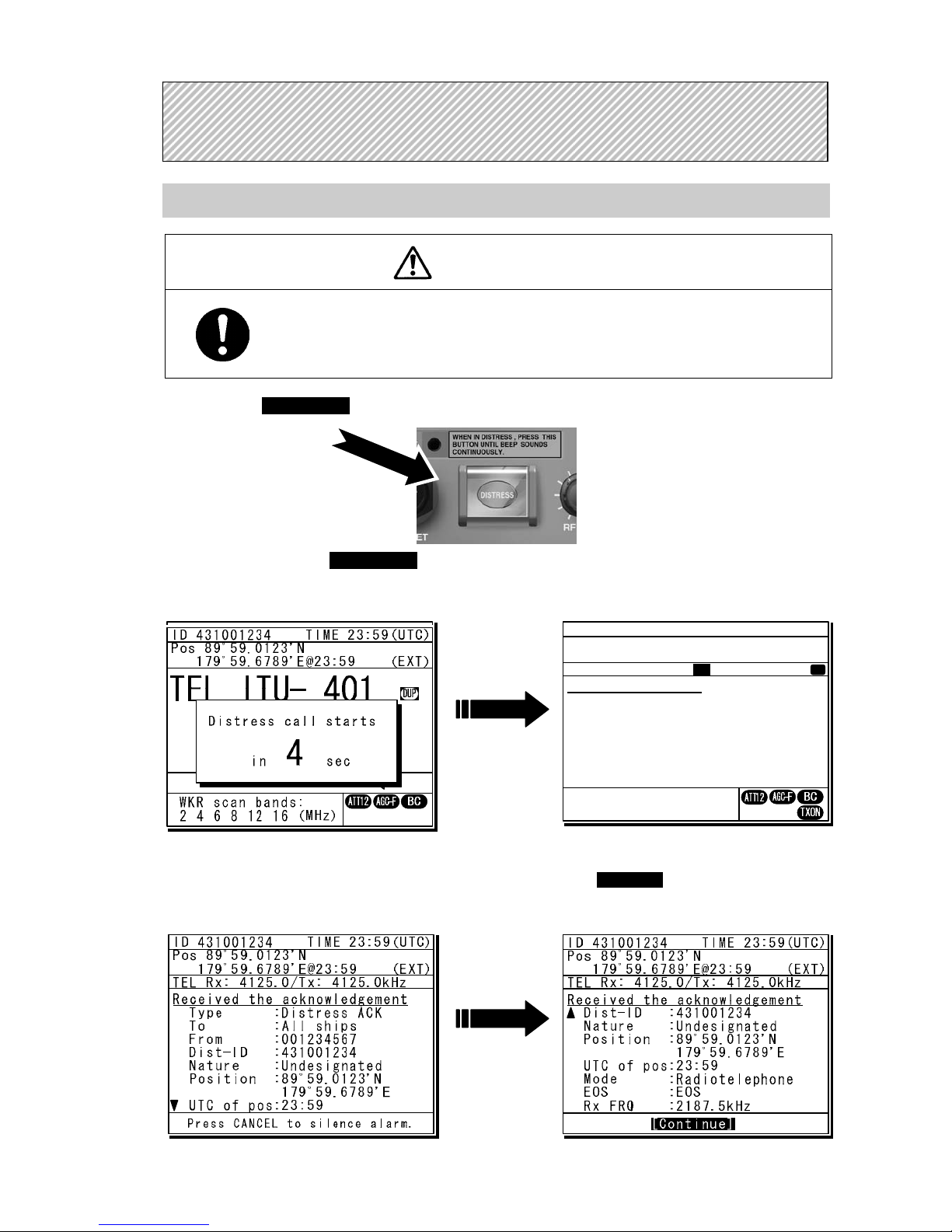
Sending a Distress Call (Distress Alert)
CAUTION
When sending a distress call, follow the instructions of the ship's captain or officer in
charge.
1
1
1
.
.
.
Open the DISTRESS key cover on the NCM-2150 MF/HF CONTROLLER.
2
2
2
.
.
.
Press and hold the DISTRESS key for 4 seconds to send the distress call.
When the countdown is finished the screen below on the right is displayed, and after tuning the
antenna to the frequency, the distress call is transmitted.
3
3
3
.
.
.
After sending the distress call, wait for an acknowledgement.
The radiotelephone can be used to communicate even while waiting for an acknowledgement. The screen
below is displayed when an acknowledgement is received. Press the CANCEL key or ENT to cancel the
alarm, and then select Continue with the jog dial and press ENT. Unless an acknowledgement is received or
the distress call is cancelled manually, the equipment repeats the distress call every 3.5 to 4.5 minutes.
D
D
D
I
I
I
S
S
S
T
T
T
R
R
R
E
E
E
S
S
S
S
S
S
C
C
C
A
A
A
L
L
L
L
L
L
S
S
S
ID 431001234 TIME 23:59(UTC)
Pos 89゚59.0123'N
179゚59.6789'E@23:59 (EXT)
DSC Rx: 2177.0/Tx: 2177.0kHz
3)Editing a distress msg
Format :Distress
Self-ID :431001234
Nature :Undesignated
Position : 89゚59.0123'N
179゚59.6789'E
UTC of pos :23:59
Comm type :Radiotelephone
EOS :EOS
[Return] [Tips] [Cancel]
Distress call starts
in sec
4
ID 431001234 TIME 23:59(UTC)
Pos 89゚59.0123'N
179゚59.6789'E@23:59 (EXT)
DSC Rx: 2187.5/Tx: 2187.5kHz
Distress calling
Stage :Transmitting
Next :-- Call-F:2187.5/4207.5/6312.0
(kHz) 8414.5/12577.0/16804.5
[MoreInfo]
WKR scan bands:
2 4 6 8 12 16 (MHz)
Tx
T
Page 14

xii
4
4
4
.
.
.
After receiving acknowledgement, use the radiotelephone to request rescue.
First, the responding station calls by radiotelephone. Communicate the following information to that station.
z Say "MAYDAY".
z Say "This is (name of your ship)".
z Tell the station the ship's Maritime Mobile Service Identity (MMSI) number, call sign, ship's position,
nature of distress, and rescue requests.
If time permits, enter the nature of the distress or the mode (Radiotelephone or FEC) as follows,
just before sending the distress call. (For more details, see 4.5.3.)
1) Open menu 3. Editing a distress msg.
2) Press ENT in the screen displayed at right
and select the nature of the distress.
3) Press ENT to confirm the selection.
The nature of the distress is set. If the position
and time (UTC) are not displayed automatically
for any reason, input them manually at this time.
4) Press and hold the DISTRESS key for 4
seconds to send the distress call.
The rest of the procedure is the same as
described above.
Terminating a Distress Call
CAUTION
If a false distress call is transmitted accidentally, follow the instructions below:
1. Press the CANCEL key on the controller (when appropriate, follow the commands on
screen) and terminate the transmission of the distress call.
2. Report the false distress call to a nearby RCC (Rescue Coordination Center).
(In Japan, inform the nearest Japan Coast Guard.)
Information to be reported:
The date/time, location, and reason why the false distress call was transmitted. Also
report the ship's name, type, nationality, ID number as well as the unit model name and
manufacture number/date, if possible.
3. Report the false distress call to nearby ships using 2182.0 kHz or another frequency for
distress and safety purposes on the radiotelephone.
4. If any acknowledgements to the distress call are received, inform the ships of the false
distress call.
Press the CANCEL key on the NCM-2150 MF/HF CONTROLLER.
If the CANCEL key is pressed during transmission of the distress call, the screen immediately returns to
the status display.
If the CANCEL key is pressed in the interval between automatic resending of the distress call, the screen
shown below is displayed. Select Break with the jog dial and press ENT to return to the status display.
Note
ID 431001234 TIME 23:59(UTC)
Pos 89゚59.0123'N
179゚59.6789'E@23:59 (EXT)
TEL Rx: 8291.0/Tx: 8291.0kHz
Distress calling
Stage :Waiting for ACK
Next :Resends 0.2min later
Call-F:2187.5/4207.5/6312.0
(kHz) 8414.5/12577.0/16804.5
[MoreInfo]
[MoreInfo]
WKR scan bands:
2 4 6 8 12 16 (MHz)
- Attention Now continuing the
distress call mode.
Break this mode?
[Continue] [Break]
[Continue]
ID 431001234 TIME 23:59(UTC)
Pos 89゚59.0123'N
179゚59.6789'E@23:59 (EXT)
DSC Rx: 2177.0/Tx: 2177.0kHz
3)Editing a distress msg
Nature :[Undesignated ]
Position :[NE]
[ 89゚59.0123'N]
[179゚59.6789'E]
UTC of pos :[23:59]
Mode :[Radiotelephone]
Attempt type:[Multi-FRQ ]
Tx bands :[2/4/6/8/12/16]
[Preview] [Tips] [Cancel]
Nature
Page 15

xiii
Receiving a Distress Call
WARNING
If a distress call is received, make sure to inform the ship's captain or officer in charge.
Doing so may save the lives of the crew and passengers on the ship in distress.
1
1
1
.
.
.
When a distress call is received, the distress message is displayed.
The ALM lamp starts blinking, and an alarm gradually grows louder.
2
2
2
.
.
.
Press the CANCEL key to stop the alarm and then move the cursor to "Accept" after
scrolling by the jog dial and press ENT.
Because the specified communicate mode and the distress frequency of the frequency band received message are set,
keep watch under such a condition. Keep watch for five minutes or more, and executes the report to the coast station etc.
as appropriate
3
3
3
.
.
.
To respond to the distress call and coordinate with the coast station, select acknowledge
(ACK) from the menu in 4. DSC logs and send it. After sending it, communicate with the
ship in distress via the radiotelephone as follows.
z Say "MAYDAY".
z Repeat the identity (MMSI) of the ship in distress 3 times
z Say, "This is".
z Repeat the identity (MMSI) of your ship 3 times
z Say "RECEIVED MAYDAY".
ID 431001234 TIME 23:59(UTC)
Pos 89゚59.0123'N
179゚59.6789'E@23:59 (EXT)
TEL Rx: 4100.0/Tx: 4100.0kHz
Received distress message
Type :Distress
From :431022222
Nature :Man overboard
Position :90゚00.0000'N
180゚00.0000'E
UTC of pos:23:57
Mode :Radiotelephone
EOS :EOS
Press CANCEL to silence alarm.
TEL
2182.0
2182.0
RX kHz
TX kHz
WKR scan bands:
2 4 6 8 12 16 (MHz)
ID 431001234 TIME 23:59(UTC)
Pos 89゚59.0123'N
179゚59.6789'E@23:59 (EXT)
SIG
ID 431001234 TIME 23:59(UTC)
Pos 89゚59.0123'N
179゚59.6789'E@23:59 (EXT)
TEL Rx: 4100.0/Tx: 4100.0kHz
[Accept] [Cancel]
Received distress message
Position :90゚00.0000'N
180゚00.0000'E
UTC of pos:23:57
Mode :Radiotelephone
EOS :EOS
Rx FRQ :2187.5/----.-/
----.-/----.-/
-----.-/-----.-kHz
[Accept]
Page 16

xiv
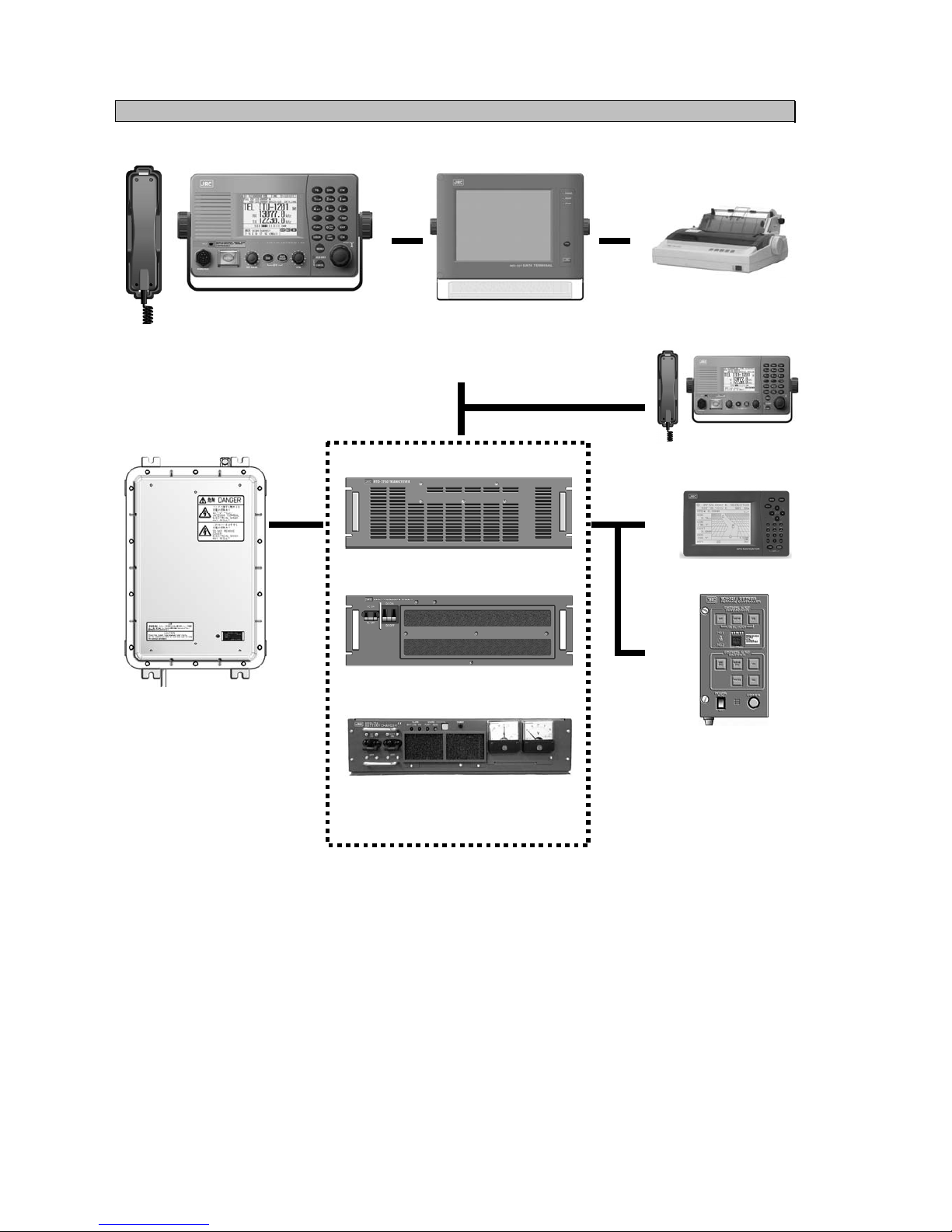
Equipment exterior
● JSS-2250/2500 (JSS-2250N/2500N) 250W/500W MF/HF Radio Equipment
Note: According to the composition, the model variants are as follows.
- JSS-2250 :250W Radiotelephone/ DSC
- JSS-2250N :250W Radiotelephone/ DSC & NBDP
- JSS-2500 :500W Radiotelephone/ DSC
- JSS-2500N :500W Radiotelephone/ DSC & NBDP
In this document, unless otherwise specified, “JSS-2250/2500” may include “JSS-2250N/2500N”.
NTD-2250/2500 Transceiver
NBD-2250/2500 Power supply NFC-2250/2500 Antenna tuner
NCM-2150 MF/HF Controller/NQW-261 Handset
Page 17

xv
NDZ-227 Data terminal / NDF-369 Keyboard
NKG-800 Printer
Page 18

xvi
● DPU-414 Printer
● NKG-91 Printer
● NBB-714 Battery charger (10A)
● NBB-724 Battery charger
● NCH-321A Distress Message Controller (DMC)
Page 19

Contents
Preface ......................................................................................................... v
Before operation ......................................................................................... vi
Handling precautions ................................................................................. viii
DISTRESS CALLS ....................................................................................... xi
Equipment exterior ..................................................................................... xiv
Glossary of terms ....................................................................................... xxi
1. EQUIPMENT OVERVIEW ........................................................................ 1-1
1.1 Functions ................................................................................................................... 1-1
1.2 Features ..................................................................................................................... 1-1
1.3 Basic configuration .................................................................................................... 1-2
1.3.1 DSC model (JSS-2250/2500) ................................................................................ 1-2
1.3.1.1 Standard components .................................................................................. 1-2
1.3.1.2 Options ........................................................................................................... 1-2
1.3.2 DSC/NBDP model (JSS-2250N/2500N) ................................................................ 1-3
1.3.2.1 Standard components .................................................................................. 1-3
1.3.2.2 Options ........................................................................................................... 1-3
1.3.3 System configuration ........................................................................................... 1-4
1.4 External dimensions .................................................................................................. 1-5
1.5 Block diagram ............................................................................................................ 1-12
1.5.1 DSC model (JSS-2250/2500) ................................................................................ 1-12
1.5.2 DSC/NBDP model (JSS-2250N/2500N) ................................................................ 1-13
2. NAMES AND FUNCTIONS ...................................................................... 2-1
2.1 Controller (NCM-2150) .............................................................................................. 2-1
2.2 Controller’s display ...................................................................................................... 2-3
2.2.1 Status display ....................................................................................................... 2-3
2.2.2 Function screen and key operations .................................................................... 2-4
2.2.3 Menu screen ........................................................................................................ 2-5
2.2.4 DSC message receiving screen .......................................................................... 2-5
2.3 Data terminal(NDZ-227) ......................................................................................... 2-6
2.4 Display of data terminal ............................................................................................... 2-7
2.4.1 Regular screen ..................................................................................................... 2-7
2.4.2 Telex communication screen ................................................................................ 2-8
2.4.3 Message file edit screen ...................................................................................... 2-9
3. INSTALLATION ........................................................................................ 3-1
Page 20

4. OPERATION ............................................................................................ 4-1
4.1 Operation overview ................................................................................................... 4-1
4.1.1 Operation of the controller .................................................................................... 4-1
4.1.2 Operation of the data terminal ............................................................................. 4-3
4.2 Basic communications procedure ............................................................................. 4-5
4.2.1 Turning on the power .......................................................................................... 4-5
4.2.2 Turning off the power/ Putting into sleep mode ................................................... 4-6
4.2.3 Communicating in radiotelephone mode ............................................................ 4-7
4.2.4 Communicating in CW mode .............................................................................. 4-9
4.2.5 Receiving AM broadcasts .................................................................................... 4-11
4.2.6 Communicating in telex mode (TLX) ................................................................... 4-12
4.2.6.1 ARQ mode operation ................................................................................... 4-12
4.2.6.2 CFEC mode operation ................................................................................. 4-15
4.2.6.3 SFEC mode operation ................................................................................. 4-19
4.2.6.4 Editing telex messages ................................................................................ 4-21
4.3 Setting the radio ........................................................................................................ 4-24
4.3.1 Setting the communication frequencies .............................................................. 4-24
4.3.2 Setting the communication channels .................................................................. 4-25
4.3.3 Setting the automatic gain control (AGC) ........................................................... 4-29
4.3.4 Setting the noise reduction (NR) ......................................................................... 4-29
4.3.5 Setting the attenuation (ATT) .............................................................................. 4-30
4.3.6 Setting the clarifier ............................................................................................... 4-30
4.3.7 Setting the squelch level ..................................................................................... 4-31
4.3.8 Setting the CW bandwidth ................................................................................... 4-31
4.3.9 Scanning the Rx frequencies .............................................................................. 4-32
4.3.10 Reducing the Tx power ....................................................................................... 4-34
4.3.11 Setting the antenna tuning power ....................................................................... 4-34
4.3.12 Setting the Auto Tune Start (ATS) function .......................................................... 4-34
4.4 Basic DSC operations ................................................................................................. 4-35
4.4.1 Routine calls to an individual station ................................................................... 4-35
4.4.2 Routine calls to a group of ships ......................................................................... 4-38
4.4.3 Receiving routine calls ........................................................................................ 4-40
4.5 Emergency calls (DSC safety/urgency/distress calls) ................................................ 4-44
4.5.1 Safety calls .......................................................................................................... 4-44
4.5.1.1 Individual calls ............................................................................................. 4-44
4.5.1.2 Area calls ..................................................................................................... 4-46
4.5.1.3 Other features of the safety calls (position request/test) ............................... 4-48
4.5.1.4 Receiving safety calls .................................................................................. 4-52
4.5.2 Urgency calls ....................................................................................................... 4-55
4.5.2.1 Individual calls ............................................................................................. 4-55
4.5.2.2 Area calls ..................................................................................................... 4-56
4.5.2.3 Special calls (medical transport/neutral ship) .............................................. 4-58
4.5.2.4 Receiving urgenc
y calls
............................................................................... 4-58
4.5.3 Distress calls ....................................................................................................... 4-60
4.5.3.1 Quick distress calls ...................................................................................... 4-60
4.5.3.2 Distress calls from the menu ....................................................................... 4-63
Page 21

4.5.3.3 Receiving distress calls ................................................................................ 4-66
4.5.3.4 Acknowledging a received distress call ........................................................ 4-67
4.5.4 Distress relay calls on behalf of someone else .................................................... 4-68
4.5.4.1 Coast station calls ........................................................................................ 4-68
4.5.4.2 Area calls ...................................................................................................... 4-71
4.5.4.3 Receiving drobose calls ............................................................................... 4-73
4.5.5 Distress relay calls ............................................................................................... 4-74
4.5.5.1 Sending distress relay calls .......................................................................... 4-74
4.5.5.2 Receiving distress relay calls ....................................................................... 4-76
4.6 DSC call log ............................................................................................................... 4-78
4.6.1 Received distress messages ............................................................................... 4-78
4.6.2 Received other messages ................................................................................... 4-79
4.7 Display of telex communication logs ......................................................................... 4-80
4.8 USB memory operation ............................................................................................. 4-81
4.9 Popup screens ........................................................................................................... 4-82
5. SETTINGS & REGISTRATIONS .............................................................. 5-1
5.1 Date and time settings ............................................................................................... 5-1
5.2 Own ship position and time settings .......................................................................... 5-3
5.3 Controller settings ...................................................................................................... 5-4
5.3.1 LCD adjustment ................................................................................................... 5-4
5.3.2 Sound settings ..................................................................................................... 5-4
5.3.3 User key assignments .......................................................................................... 5-5
5.3.4 Selecting Tx meters ............................................................................................. 5-6
5.3.5 Transferring user channel data to another controller ........................................... 5-7
5.4 Registering user channels ......................................................................................... 5-8
5.5 Advanced settings for DSC/WKR .............................................................................. 5-10
5.5.1 Automatic acknowledgement ............................................................................... 5-10
5.5.2 Setting DSC watch frequency .............................................................................. 5-11
5.5.3 Disabling receiving alarms for routine and safety calls ........................................ 5-11
5.5.4 Using medical/neutral settings for urgency calls .................................................. 5-11
5.5.5 Registering the ship's group ID ............................................................................ 5-11
5.6 Setting connections for options ................................................................................. 5-12
5.7 Setting of data terminal .............................................................................................. 5-13
5.7.1 LCD adjustment ................................................................................................... 5-13
5.7.2 Registering station list .......................................................................................... 5-15
5.8 Setting telex mode ..................................................................................................... 5-17
6. MAINTENANCE & INSPECTION ............................................................. 6-1
6.1 General maintenance & inspection ............................................................................ 6-1
6.2 Self diagnosis inspection ........................................................................................... 6-2
6.3 System alarm indication ............................................................................................ 6-5
6.3.1 Alarm list .............................................................................................................. 6-6
6.3.2 Viewing the alarm history ..................................................................................... 6-9
6.4 Software version ........................................................................................................ 6-10
6.5 Troubleshooting ......................................................................................................... 6-11
6.5.1 Procedures for locating malfunctions ................................................................... 6-11
Page 22

6.5.2 Guide to locating faults ........................................................................................ 6-12
6.5.3 Consumables ...................................................................................................... 6-13
6.5.4 Repair units/parts ................................................................................................ 6-13
6.5.5 Regular replacement parts .................................................................................. 6-14
7. AFTER-SALES SERVICE ....................................................................... 7-1
8. DISPOSAL ............................................................................................... 8-1
9. SPECIFICATIONS ................................................................................... 9-1
9.1 JSS-2250/2500 MF/HF Radio Equipment ................................................................ 9-1
9.2 Options ...................................................................................................................... 9-5
9.3 Peripheral interfaces ................................................................................................. 9-7
10. OPTIONS OPERATION ......................................................................... 10-1
10.1 Battery charger (NBB-714) ....................................................................................... 10-1
10.2 Battery charger (NBB-724) ....................................................................................... 10-3
10.3 Printer (NKG-91) ....................................................................................................... 10-5
10.4 Printer (NKG-800) ..................................................................................................... 10-6
10.5 Operations using a SELCALL unit ............................................................................ 10-9
11. Appendix ............................................................................................... 11-1
11.1 Frequencies for distress and safety calls .................................................................. 11-1
11.2 National DSC frequencies for routine calls ............................................................... 11-2
11.3 International DSC frequencies for routine calls ........................................................ 11-2
11.4 ITU channel list (TEL/CW/TLX) ................................................................................ 11-3
11.5 Guide to MF/HF operation ........................................................................................ 11-22
Declaration on toxic & hazardous substances or elements
Page 23

xxi
Glossary of terms
This section defines general and DSC terms related to this equipment.
● General terms
AMVER
Automated Mutual-assistance Vessel
Rescue System
System that informs another ship of position
of distress ship operated in the United States.
ARQ
Automatic Repeat reQuest
When communicating interactive in the telex
mode, this ARQ is used.
CFEC
Collective Forward Error Correction
When broadcasting in the telex mode, this
CFEC is used.
DSC
Digital Selective Calling device
Used in routine calls, safety and urgency
calls, and distress calls for rescue requests.
GMDSS
Global Maritime Distress and Safety System.
GPS
Global Positioning system
IMO
International Maritime Organization
ITU
International Telecommunication Union
Establishes conventions and regulations for
all electrical wired and radio, land, sea, air,
and space communications. It contains
internal organizations such as ITU-R and
ITU-T.
ITU-R
The International Telecommunications Union
(ITU) radio communications department.
JASREP
Japanese Ship Reporting System
Ship position reporting system operated in
Japan.
LT
Local time
MF/HF
Medium frequencies and high frequencies
(300 kHz to 30 MHz)
MMSI
Maritime Mobile Service Identity
The 9-digit Maritime Mobile Service Identity
number assigned to each ship and coast
station.
NBDP
Narrow Band Direct Printing
It is a generic name of the device used to
communicate in the telex mode.
NMEA
Maritime equipment transmission standard
established by the National Marine
Electronics Association.
PTT
Push to talk
RCC
Rescue Co-ordinate Center
RMS
Remote Maintenance System
Transmits ship equipment information
temporarily stored in the VDR via Inmarsat to
land, for use in maintenance and
management of radio equipment.
RR
Radio Regulations
International regulations for radio transmission
established by the treaty of the ITU.
SELCAL Number(Selective Calling Number)
Selective Calling Number by NBDP.
It is the numbers of four digits (coast station)
or five digits (Ship station) used when the
other party is specified in the telex mode.
Page 24

xxii
SFEC
Selective Forward Error Correction
When broadcasting to a specific group in the
telex mode, this SFEC is used.
SOLAS Convention
International Convention for Safety of Life at
Sea
The international convention applies to all
ships engaged on international voyages. A
safety certificate is issued if the conditions of
this convention are satisfied.
SQL
Squelch
A function that acts to suppress the audio
output of a receiver in the absence of a radio
signal of sufficient strength.
UTC
Universal Time Coordinated
VOL (Volume)
Speaker volume
WRC
World Radiocommunication Conference
WKR
Watch Keeping Receiver
The WKR is the receiver dedicated to
monitoring the distress and safety
frequencies.
● DSC terms
Address
General term for Maritime Mobile Serive
Identity number (MMSI).
This equipment uses To/From to distinguish
between the sender and receiver. It also
means the Self-ID (own ship MMSI) and
Dist-ID (MMSI of a ship in distress).
Category
Message code indicating priority of the call.
Priority levels are listed below.
・ Routine… General calls for routine work
・ Safety…
Calls for safety communications
・ Urgency…
Calls for urgent communications
・ Distress…
Calls for distress communications
EOS (End Of Sequence)
Termination code appended to call
messages.
Other codes are listed below.
・ ACK RQ… Acknowledgement request
・ ACK BQ… Acknowledgement responding
to the ACK RQ
ECC (Error Check Character)
Error check code appended to the end of call
messages.
This is not normally displayed, but if an error
occurs on a message, an ECC error is
displayed.
Mode
Message code indicating communication
mode after a DSC call.
This equipment is fixed to radiotelephone.
Radiotelephone (TEL) or ARQ and FEC
(TLX) can be used.
Nature of Distress
Message code indicating the type of distress
when a distress call is issued.
Codes are listed below.
・ Fire… Fire, explosion
・ Flooding… Flooding
・ Collision… Collision
・ Grounding… Grounding
・ Listing… Risk of ship capsizing
・ Sinking… Sinking
・ Disabled… Ship inoperable/adrift
・ Undesignated… Undesignated distress
・ Abandoning… Abandoning ship
・ Piracy attack… Piracy/robbery attack
・ Man overboard… Man overboard
Polling
Polling is a feature for routine calling.
It is used, for example, to confirm whether a
ship is within radio range when a coast
station requests navigational information of
the ship.
Reason
Message code indicating reason for negative
acknowledgement response.
Codes are listed below.
・ No reason… No reason
・ Congestion… Maritime information
exchange center
congested
Page 25

xxiii
・ Busy… Busy
・ Queue… Queued
・ Barred… Station barred
・ No operator… No operator
・ Temp no oper…
Temporarily no operator
・ EQP disabled… Equipment disabled
・ Unable FRQ… Indicated frequency
cannot be used
・ Unable mode…
Indicated mode cannot
be used
Rx FRQ
Received frequency of the call
Subject
Message code clarifying communication
contents when sending an urgency call to all
ships.
When sailing in dangerous waters, such as
in areas of political instability, these call
messages are used with the following
information.
・ Neutral ship: In accordance with ITU
resolution 18 (Mob-83), inform all ships
that own ship is of neutral nationality.
・ Medical TRANSP: Inform all ships
that own ship is performing medical
transportation, and is protected under the
1949 Geneva Convention.
Topic
Message codes in an acknowledged message
After sending an individual call, "Unable to
comply" is displayed when the responding
station cannot comply.
Type
Message code indicating the type of the call.
Codes are listed below.
・ Individual call… Individual call message
・ Individual ACK… Acknowledgement of
individual call message
・
Individual NACK… Negative acknowledgement
of individual call message
・ Group call… Group call message
・ GEO area call… Area call message
・ All ships call… Call to all ships
・ Distress… Distress call message
・ Distress ACK… Acknowledgement of
distress call message
・ Distress relay… Distress relay message
・
Distress relay ACK
… Acknowledgement of
distress relay message
・
Distress relay GEO
… Area call of distress
relay message
Intent
Message code indicating specific content.
Indicates the type of the call for a specific
purpose, not for radiotelephone
communication.
・ Polling… Polling
・ Position RQ… Ship position request
・ Ship position…
Ship position notification
・ Test… Safety test call
Work FRQ
Message code indicating communication
frequency after a DSC call.
Page 26

xxiv
Page 27

Equipment Overview
1-1
1. EQUIPMENT OVERVIEW
1.1 Functions
This equipment includes MF/HF transceiver, Class-A DSC and DSC watch keeping receiver required
as the Global Maritime Distress and Safety System (GMDSS). It is designed as a separated
transceiver and small, lightweight controller(s) for easy installation not only in SOLAS Convention
ships such as international passenger ships and freight ships of 300 tons or more, but also
non-conventional ships of less than 300 tons.
As for the main communication function, in addition to the communications of radiotelephone with the
handset and the Morse communication with the CW keyer, calling by digital selective calling (DSC) for
a general or distress communication are possible. Furthermore, if the data terminal is connected to the
controller, the telex communication in the ARQ or FEC mode using the NBDP is available.
1.2 Features
● Compliant with the ITU Radio Regulations (RR), the IMO performance standards, and the ITU-R
recommendations.
● Contains all channels specified in the ITU Radio Regulations (RR).
● The separately designed controller and main unit enable easy installation in limited or difficult
spaces.
● A semi-transmissive LCD with a wide viewing angle is easily viewable even in direct light or when
backlit and allows it to be installed in a variety of positions.
● The backlights of the LCD and operation keys are fully adjustable, preventing interference with
night watch keeping.
● When in distress, the DSC can send a distress message with the expanded position data accurate
up to 1/10000 of a minute for both latitude and longitude to make search and rescue operations by
the RCC easier.
● High-quality stable operation is possible by using DSP technology on a transceiver with a
DSC/WKR modem.
● The DSC operates in Class A mode suitable for all areas, and in Class B mode limited to ships
navigating in A1 and A2 areas.
● An advanced digital audio amplifier with a built-in loud speaker provides a maximum of 5 W of
clear audio.
● The maintenance and the check can be easily done at daily or the regular services, because a
special function key was prepared for the DSC safety test calling and the self-diagnosis.
● It is possible to operate on the screen with the character color and the background color
corresponding to the favor because the data terminal for the telex communication by NBDP
adopted the color liquid crystal display of the wide viewing angle in high brightness.
● Besides printers and GPS, other peripherals such as the remote maintenance system (RMS) can
be connected to the equipment.
Page 28

Equipment Overview
1-2
1.3 Basic configuration
1.3.1 DSC model (JSS-2250/2500)
11..33..11..11
Standard components
No. Description Model Qty Notes
1 Transceiver
NTD-2250/2500
1 For 250W and 500W respectively
2 Power supply
NBD-2250/2500
1 For 250W and 500W respectively
3 MF/HF controller NCM-2150 1
3-1 Controller cable 7ZCJD0343 1 5m
3-2 Handset NQW-261 1 Includes the cradle
4 Antenna tuner NFC-2250/2500 1 For 250W and 500W respectively
5 Instruction manual 7ZPJD0535 1 This manual
11..33..11..22
Options
No. Description Model Notes
1 Battery charger NBB-724 22A
2 Battery charger NBB-714 10A *For maintenance-free sealed battery only
3 Joint box JQD-69C For both RX and WKR
4 Junction box NQD-2253
5 Coaxial connector M-P-7, M-A-JJ For RG-12/UY and RG-10/UY
6 MF/HF controller NCM-2150 One additional controller available.
6-1 Controller cable 7ZCJD0343 5m
6-2 Handset NQW-261 Waterproof type (IP66 equivalent)
6-3 Flush mounting bracket MPBC42957
6-4 Mounting bracket MPBX44354
6-5 Connection box NQD-2250
For extension and expansion of the controller
7 Printer NKG-800
Desktop type
7-1 Printer connection cable 6ZCSC00407
7-2 Printer power cable 6JNKD00100B
7-3 Printer paper 5ZPCM00006
7-4 Ink ribbon (SP-16051) 5ZZCM00003
8 Printer NKG-91
Wall mount or
flush mount type
8-1 Printer connection cable 7ZCJD0254A
8-2 Printer paper 7ZPJD0384
8-3 Wall mounting bracket MPBP31446
9 Printer DPU-414
Desktop type
9-1 Printer connection cable 7ZCJD0254A
9-2 Printer power cable 7ZCJD0257C
9-3 Printer paper 6ZCAF00252A
10
Distress message controller
NCH-321A
Page 29

Equipment Overview
1-3
1.3.2 DSC/NBDP model (JSS-2250N/2500N)
11..33..22..11
Standard components
No. Description Model Qty Notes
1 Transceiver
NTD-2250/2500
1 For 250W and 500W respectively
2 Power supply
NBD-2250/2500
1 For 250W and 500W respectively
3 MF/HF controller NCM-2150 1
3-1 Controller cable 7ZCJD0343 1 5m
3-2 Handset NQW-261 1 Includes the cradle
4 Antenna tuner NFC-2250/2500 1 For 250W and 500W respectively
5 Data terminal NDZ-227 1
NBDP option
5-1 DTE cable 7ZCJD0388 1
5-2 DTE power cable 7ZCJD0419 1
5-3 Keyboard NDF-369 1
6 Printer NKG-800 1
6-1 Printer connection cable 7ZCSC0205A 1
6-2 Printer power cable 6JNKD00100B 1
7 Instruction manual 7ZPJD0535 1 This manual
11..33..22..22
Options
No. Description Model Notes
1 Battery charger NBB-724 22A
2 Battery charger NBB-714 10A *For maintenance-free sealed battery only
3 Joint box JQD-69C For both RX and WKR
4 Junction box NQD-2253
5 Coaxial connector M-P-7, M-A-JJ For RG-12/UY and RG-10/UY
6 MF/HF controller NCM-2150 One additional controller available.
6-1 Controller cable 7ZCJD0343 5m
6-2 Handset NQW-261 Waterproof type (IP66 equivalent)
6-3 Flush mounting bracket MPBC42957
6-4 Mounting bracket MPBX44354
6-5 Connection box NQD-2250
For extension and expansion of the controller
7 Data terminal NDZ-227
For expansion of the controller
7-1 DTE cable 7ZCJD0388
7-2 DTE power cable 7ZCJD0419
7-3 Keyboard NDF-369
7-4 Mounting bracket MPBP31721
7-5 USB memory UDG4-1GAR-JRC Hagiwara Sys-Com / 1GB
8 Printer NKG-800
Desktop type
8-1 Printer connection cable 7ZCSC0205A
8-2 Printer power cable 6JNKD00100B
8-3 Printer paper 5ZPCM00006
8-4 Ink ribbon (SP-16051) 5ZZCM00003
9 Printer NKG-91
Wall mount or
flush mount type
9-1 Printer connection cable 7ZCJD0254A
9-2 Printer paper 7ZPJD0384
9-3 Wall mounting bracket MPBP31446
10 Printer DPU-414
Desktop type
10-1 Printer connection cable 7ZCJD0254A
10-2 Printer power cable 7ZCJD0257C
10-3 Printer paper 6ZCAF00252A
11
Distress message controller
NCH-321A
Page 30
Equipment Overview
1-4
1.3.3 System configuration
NCH-321A DMC
GPS
NTD-2250/2500 Transceiver
Expansion Controller
* The equipment can also be
connected to the VDR
server to use the remote
maintenance system.
NFC-2250/2500
Antenna Tuner
NCM-2150 MF/HF Controller
NQW-261 Handset
NKG-800 Printer
NDZ-227 Data terminal
NDF-369 Keyboard
(DSC/NBDP model only)
NBD-2250/2500 Power supply
NBB-724 Battery charger
Page 31

Equipment Overview
1-5
1.4 External dimensions
Below are the external dimensions of each unit.
(1) Transceiver (NTD-2250/2500)
(2) Power Supply (NBD-2250/2500)
Unit: mm
Weight: Approx. 15 kg/ 17 kg
Unit: mm
Weight: Approx. 15 kg/ 18 kg
Note) This figure shows the NTD-2250.
Incase of the NTD-2500, 3 fans are
mounted on the back.
Page 32

Equipment Overview
1-6
(3) MF/HF Controller (NCM-2150)
(4) Handset (NQW-261)
(5) Connection box (NQD-2250)
Unit: mm
Weight: Approx. 0.5 kg
Unit: mm
Weight: Approx. 1.3 kg
Mounting
hole
Unit: mm
Weight: Approx. 0.6 kg
Page 33

Equipment Overview
1-7
(6) Antenna Tuner (NFC-2250/2500)
(7) Junction Box (NQD-2253)
Unit: mm
Weight: Approx. 1.2 kg
Unit: mm
Weight: Approx. 10 kg/ 10 kg
Page 34

Equipment Overview
1-8
(8) Data Terminal (NDZ-227)
(9) Keyboard (NDF-369)
Unit: mm
Weight: Approx. 0.4 kg
Unit: mm
Weight: Approx. 4.6 kg
Page 35

Equipment Overview
1-9
(10) Printer (NKG-800)
● Desktop type
(11) Printer (DPU-414)
● Desktop type
Unit: mm
Weight: Approx. 3.7 kg
Unit: mm
Weight: Approx. 0.6 kg
Page 36

Equipment Overview
1-10
(12) Printer (NKG-91)
● Wall mount type
● Flash mount type
Unit: mm
Weight: Approx. 1.5 kg
Unit: mm
Weight: Approx. 0.8 kg
Page 37

Equipment Overview
1-11
(13) Battery Charger (NBB-714)
(14) Battery Charger (NBB-724)
Unit: mm
Weight: Approx. 12 kg
Unit: mm
Weight: Approx. 8.6 kg
Page 38

Equipment Overview
1-12
1.5 Block diagram
1.5.1 DSC model (JSS-2250/2500)
24V DC
200Ah
GPS
AME
RMS
(VDR)
DPYC-16
TTYCS- 1
MPYCS- 7
TTYCS- 1
TTYCS- 4
100V/220V AC
50/60Hz 1φ
NCH-321A
DMC
DPYC-25
RG-12/UY
RX/WKR ANT
TX
ANT
M-P-7
Tx antenna
Rx/WKR
antenna
TTYCS- 4
DPYC-2.5
7ZCJD
0343
(5m)
NQD-2250
Connection
box
NFC-2250/2500
Antenna tuner
TX ANT
Lead wire
TH-19/1.2
NCM-2150
MF/HF Controller
NQW-261
Handset
JQD-69C
Joint box
NQD-2250
Connection
box
Expansion controller
7ZCJD0254A
TTYCS- 4
DPYC-2.5
NKG-91
Printer
6.5V DC
NTD-2250/2500
Transceiver
NBD-2250/2500
Power supply
NBB-724
Battery charger
7ZCJD
0426
M-P-7
TTYCYS-4
NQD-2253
Junction
box
RG-10/UY
M-P-7/M-P-5
M-A-JJ
Page 39

Equipment Overview
1-13
1.5.2 DSC/NBDP model (JSS-2250N/2500N)
RG-12/UY
7ZCJD
0426
M-P-7
M-P-7
Tx antenna
Rx/WKR
antenna
TTYCS- 4
DPYC-2.5
7ZCJD
0343
(5m)
NQD-2250
Connection
box
NFC-2250/2500
Antenna tuner
TX ANT
TTYCYS-4
Lead wire
TH-19/1.2
NQD-2253
Junction
box
NCM-2150
MF/HF Controller
NQW-261
Handset
JQD-69C
Joint box
RG-10/UY
M-P-7/M-P-5
M-A-JJ
NDZ-227
Data terminal
NDF-369
Keyboard
NKG-800
Printer
NQD-2250
Connection
box
Expansion controller
7ZCJD0419
6JNKD00100B
7ZCJD0388
7ZCSC0205A
TTYCS- 4
DPYC-2.5
GPS
AME
RMS
(VDR)
TTYCS- 1
MPYCS- 7
TTYCS- 1
TTYCS- 4
NCH-321A
DMC
NTD-2250/2500
Transceiver
NBD-2250/2500
Power supply
NBB-724
Battery charger
RX/WKR ANT
TX
ANT
24V DC
200Ah
DPYC-16
100V/220V AC
50/60Hz 1φ
DPYC-25
Page 40

Equipment Overview
1-14
Page 41

Names and Functions
2-1
2. NAMES AND FUNCTIONS
2.1 Controller (NCM-2150)
The controller parts and their functions are described below.
1. Internal loud speaker
2. Jack for telegraph in continuous wave (CW) mode
3. Black and white liquid crystal display unit
4. Numeric keypad (10-key) and function keys
In addition to entering numeric values, when combined with the
FUNC key, the keys have the following functions.
・ TEL ··· Displays the status display in TEL mode.
・ DSC ··· Displays the status display in DSC mode.
・ CW ··· Displays the status display in CW mode.
・ 1CLAR ··· Displays the setting screen for the clarifier.
・ 2SCAN ··· Displays the scan menu.
・ 3NR ··· Displays the setting screen for noise reduction.
・ 4AT T ··· Displays the setting screen for attenuation.
・ 5AGC ···
Displays the setting screen for automatic gain control.
・ 6SP ··· Turns speaker on or off.
・ 7PRN ··· Prints the specified screen.
・ 8TEST ··· Displays the self-diagnosis menu.
・ 9 ··· Switches Tx power between high and low.
・ 0 ··· Displays the DSC test call menu.
・ FUNC ··· Enables functions assigned to number keys.
PWR
RDC
TEST
CALL
1
4
5
14 6 7 8 9 10 11 12 13
2
3
15
16
Page 42

Names and Functions
2-2
・ ENT ····· Enter key.
・ USER ····· User defined key. Register a frequently used menu and use this key to open it
quickly.
・ ····· Tunes the antenna.
・ CH ····· Sets the communication channel input mode (user channel, ITU channel, or free
frequency).
5. Jog dial
- On the status display, rotating the jog dial changes the channel or Rx frequency.
- On a menu or popup screen, rotating the jog dial moves the cursor position or screen
contents. When selecting a button or an item on the screen, rotate the jog dial until the
cursor is on it and then press the jog dial.
Press the jog dial to obtain access rights from another controller.
6. Handset connector
7. DISTRESS key (Under a clear cover with spring)
When in distress, sends a DSC distress call when pressed and held for 4 seconds.
8. RF GAIN control
Adjusts sensitivity level.
RF GAIN is set to maximum just after DSC or TLX mode is set, regardless of the
position of the control.
9. DIM (Dimmer) key
Adjusts dimmer level (Max → Typ → Min → Off) of the LCD display and key switches.
Additionally used to put into sleep mode by pressing it in combination with the key at the
same time (a confirmation screen is displayed).
・ The adjusted dimmer level is not saved. When the controller is powered off
and on again, the dimmer level is always set to Typ (default).
・ If a DSC message is received, the dimmer adjustment cycle becomes "Max →
Typ → Typ → Typ" while the receiving alarm is activated.
10. PWR/CONT (Power/Contrast) key
Turns on the equipment or changes the controller from sleep mode to standby. Once turned on,
this key is also used to adjust the LCD contrast.
11. VOL (Volume) control
Adjusts volume of built-in loud speaker.
12. ALM/WKR (Alarm/Watchkeeping receiver) lamp
Lights up red on any malfunction detected in the equipment or after sending a DSC distress call,
or blinks red on receiving a DSC call. Lights green to indicate the DSC watchkeeping receiver is
operating while the equipment is in sleep mode.
13. CANCEL key
Cancels menus or stops alarms.
14. MENU key
Displays menu list.
15. Handset
When using in radiotelephone mode, press and hold the PTT key to talk.
16. Cradle (for handset)
ANT
TUNE
Note
Note
Note
PWR
CONT
Page 43

Names and Functions
2-3
2.2 Controller’s display
The LCD screen on the controller changes according to current conditions. This section
describes the status display, FUNC menu, main menu, and DSC message receiving
screens.
2.4.1 Status display
1. Occupied mark. Indicates another controller
has the access rights.
2. Indicates the ship's MMSI.
3. Indicates the ship's position and that time.
4. Indicates the communication mode and
channel.
5. Indicates the receiver is scanning.
6. Indicates Tx power reduction state (incase
of MED or LOW).
7. Indicates the following conditions if Tx
frequency is not tuned.
z Not tuned : Blinks
z Tuning : Lights
z Tuned : Off
8. When in reception or standby, indicates
strength of received signal (S meter), or
when in transmission, indicates strength of
transmitted signal in one of the pre-set
units shown below.
z Tx power (PWR)
z Antenna current (Ia)
z PA voltage (Vc)
z PA current (Ic)
z Key information (KEY)
Note: When transmitting in ARQ mode, KEY
is displayed regardless of the above
mentioned setting.
9. Indicates the frequency (band) the DSC
watch keeping receiver is monitoring for
distress and safety calls.
10. Indicates the equipment is running on DC
power.
11. Indicates current time as follows:
z Universal time coordinated : UTC
z Local time : LT
12. Indicates the source of the ship's position
information as follows.
z External device (e.g. GPS) : EXT
z Manual input : MAN
z No input : OFFLINE
13. Indicates the user channel in use is
transmitted at the band power level
because the channel power is not
registered.
14. Indicates channel or frequency is duplex
for communicating with a coast station.
15. Indicates the reception frequency.
16. Indicates the transmission frequency. TX
mark is highlighted when transmitting.
17. Indicates the built-in loud speaker is on or
off. indicates the squelch is on.
18. Indicates the reception status (attenuation,
AGC, noise reduction) and transmission
status (PA power).
TEL ITU-1201
13077.0
12230.0
RX kHz
TX kHz
TX
WKR scan bands:
2 4 6 8 12 16 (MHz)
ID 431001234 TIME 23:59(UTC)
Pos 89゚59.0123'N
179゚59.6789'E@23:59 (EXT)
SIG
*
10
12
14
16
17
6
5
4
3
2
1
11
8
15
18
7
13
9
Page 44
Names and Functions
2-4
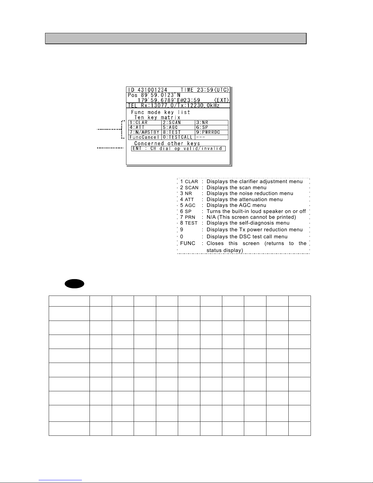
2.4.2 Function screen and key operations
The functions assigned to the number keys are temporarily enabled by pressing the FUNC
key in the status display or pressing and holding the FUNC key and then pressing the
number key.
1. Indicates the enabled number key and its
function when the FUNC key is pressed in
the status display. Pressing the number
keys here operates the function for that
key as shown at the right.
1
CLAR : Displays the clarifier adjustment menu
2
SCAN : Displays the scan menu
3
NR : Displays the noise reduction menu
4
ATT : Displays the attenuation menu
5
AGC : Displays the AGC menu
6
SP : Turns the built-in loud speaker on or off
7
PRN : N/A (This screen cannot be printed)
8
TEST : Displays the self-diagnosis menu
9 : Displays the Tx power reduction menu
0 : Displays the DSC test call menu
FUNC : Closes this screen (returns to the
status display)
2. Indicates that pressing ENT enables or disables the use of the jog dial to change the frequency
and channel in the status display.
In the following situations the function assigned to the function key cannot be used.
Equipment
status
1
CLAR 2SCAN 3NR 4ATT 5AGC 6SP 7PRN 8TEST 9
WR
DC
0
TEST
CALL
DSC mode
●
●
In status display
while inputting
frequency
● ● ● ● ● ● ● ● ● ●
While tuning
antenna or
transmitting
● ● ● ● ● ● ● ● ● ●
While printing
● ● ● ● ● ● ● ● ● ●
During
self-diagnosis
● ● ● ● ● ● ● ● ● ●
While
scanning
●
●
●
While waiting for
DSC
acknowledgement
● ● ●
● ●
●
While just
received DSC
message is
displa
y
ed
● ● ● ● ●
While alarm
screen is
displayed
● ● ● ● ● ● ● ● ● ●
1
2
Note
PWR
RDC
TEST
CALL
Page 45

Names and Functions
2-5
2.4.3 Menu screen
1. Indicates the current menu name.
2. Indicates the menu content. The cursor line
or position is highlighted. Select items with
the jog dial and press ENT to confirm.
3. Indicates the main radio information the
same as the status display. Also indicates
the following marks in the frequency
information area according to the
conditions.
T : Performing the antenna tuning
(Blinking means “Not tuned”.)
M : Tx power is Medium.
L : Tx power is low.
2.4.4 DSC message receiving screen
1. Indicates the received message category.
(Routine, Safety, Urgency, Distress)
2. Shows the received message. The example
above shows the following contents.
¾ Type : Individual call to own ship
¾ From : The caller's MMSI is
123456789.
¾ Mode : Radiotelephone is
requested as a subsequent
communication type.
¾
Work FRQ
: Indicates the proposed
working channel
¾ EOS : Acknowledgement
requested
¾ Rx FRQ : The received frequency of
this call
3. Indicates message handling menu for
received message. The example above
shows the following.
z [Accept]
Select to agree to the call, and start
radiotelephone communications
immediately.
z [Unable]
Select to not agree to the call, and
reply to the call as "unable to comply".
z [NewCH]
Select to agree to the call except on
the proposed channel, and reply to
the call with a new channel proposal.
z [Cancel]
Return to the previous screen.
・ When [Unable] or [NewCH] is selected, an editing screen appears.
・ In the case of the position request, test, and polling calls, if the Auto ACK setting
is on and acknowledged automatically, the receiving screen is not displayed. Also,
when the Auto ACK setting is off, the above receiving screen is displayed and
[Send ACK] appears for sending the acknowledgement.
・ If the receiving error is occurred, the screen shows “Detected ECC error” and any
asterisks at the places of the error characters.
3
1
2
1
2
3
Note
Page 46

Names and Functions
2-6
2.3 Data terminal(NDZ-227)
This section describes the name of each part in the data terminal and the function.
1. Color liquid crystal display (LCD) unit
2. POWER lamp
This lamp lights to green while operating the
data terminal, and blinks during the sleep.
3. READY lamp
This lamp lights to green while serial communications are being normally done. And, when
abnormality occurs, it turns off.
4. COMM lamp
This lamp lights to green while communicating in ARQ or FEC mode.
5. DIM (Dimmer) key
This key adjusts the brightness of the LCD screen and the lamp by four stages (high, middle, low,
and off).
6. Connector for the USB memory with the water-proof rubber cap
Pull out the rubber cap and connect the USB memory.
7. Keyboard
7
1
2
5
6
3
4
Page 47
Names and Functions
2-7
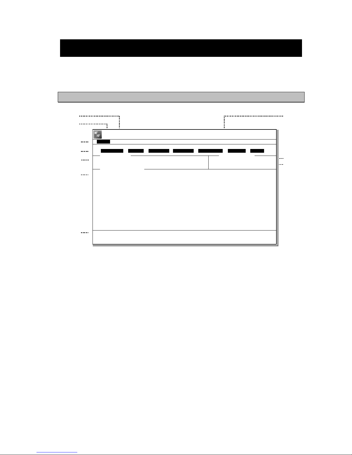
2.4 Display of data terminal
The content displayed on the LCD screen in the data terminal is different according to the
situation. This section describes a regular screen, the telex communication screen, and the
message file edit screen.
2.4.5 Regular screen
1. Indicates the Tx and Rx frequencies.
2. Indicates the communication mode.
3. Indicates the main menu.
When pressing the Enter key, indicates
the drop-down menu of the main menu
pointed by the cursor.
※Telex mode only.
4. Indicates the conditions of the telex
communication.
※Telex mode only.
5. Indicates the scanning information in telex
mode. When restarting scanning after
sending a DSC Auto-ACK or powering
off/on, indicates “Running now” instead of
the detail information.
※Telex mode only.
6. Indicates the operation result such as the
self-diagnosis.
7. Indicates the guide according to the
cursor position. Moreover, the locating
faults are displayed if any errors occur.
z Information: MEM : Internal memory
z Information: KBD :Keyboard control
z Information: PRN : Printer
z Information: USB :USB Memory
8. Indicates that the connected USB memory
is available. Additionally, “ACS” is shown
if some time is needed to mount the USB
memory.
9. Indicates the antenna tuning condition.
z READY :Tuned
z NOT READY : Not tuned
10. Indicates the power reduction setting.
2
1
8
3
4
5
6
9
7
10
[TLX] Tx= 2174.5kHz/Rx= 2174.5kHz USB
File Tune Connect Service System Help
STATUS INFO
ST-BY
[No scanning] TUNER :[READY]
Tx.POWER :[HIGH]
Move the cursor to the item you want with ↑, ↓, →, ← then press Enter.
File manager.
Information:MEM KBD PRN USB (Press the <Alt>+I if you want to know detail.)
File
Free sig. ST-BY
Calling
Receive
Rephasing Repeat Traf
Scanning info
Tuner/Tx.POWER
Last status message
Page 48

Names and Functions
2-8
2.4.6 Telex communication screen
1. Indicates the operating condition of the
telex communication from the left of each
segment as follows.
1) In the autotelex mode, when the free
channel signal of the coast station is
detected, indicates the “Free Sig”.
2) Indicates the communication mode
(ARQ/CFEC/SFEC).
※ Indicates “ST-BY” in the standby
condition.
3) Indicates “Calling” at the master
station, and “Called” at the slave
station.
4) Indicates “Send” at the information
sending station, and “Receive” at the
information receiving station.
5) Indicates "Phasing" while calling and
connecting the communication
channel and “Rephasing” while
reconnecting the channel after the
channel is disconnected due to the
channel condition in ARQ mode.
6) Indicates “Repeat” in ARQ mode if
requested to send the each block or
the control signal again.
7) Indicates “Traf” while sending or
receiving information and “RQ” while
sending or receiving RQ signal.
2. Indicates the telex message or the name
of the executed function key.
3. Indicates the usable function keys guide.
Each meaning is as follows.
z F2 WRU : Requests the answer-
back code to the
corresponding station.
z F3 Hereis : Sends the answerback
code of own station.
z F4 TMS : Sends the date and the
time information.
z F5 Over : Exchange the sending
and the receiving
condition.
z F6 POLL : Acquires the sending
right if the corresponding station (sending)
tries to finish the
communication in ARQ
mode.
※ It is available only when the
corresponding station is using the
modem made of our company.
z F8 F.Send : Sends a message file.
z F10 Stop : Finishes the telex
communication.
1
2
3
[TLX] Tx= 2174.5kHz/Rx= 2174.5kHz USB
TELEX Terminal Window
ARQ
Message start...
F2 WRU | F3 Hereis | F4 TMS | F5 Over | F8 F.Send | F10 Stop
Free sig. ARQ
Calling
Send
Rephasing Repeat Traf
Page 49

Names and Functions
2-9
2.4.7 Message file edit screen
1. Indicates the state of the edit screen as
follows.
z Editing telex file : File name
z Line :Line position of cursor
z Column :Row position of cursor
z Size :Capacity of file
z
Insert On/Overwrite :Input mode (insert/overwrite)
2. The message file is edited here.
3. The list of the function key is displayed by the
following content separately for two groups.
z Group 1
・ F1 :Insert On/Off
・ F2 :Ins_Line
・ F3 :Block
・ F4 :Del_Word
・ F5 :Del_Line
・ F6 :
・ F7 :Quit
・ F8 :Save As
・ F9 :Save & Quit
・ F10 : - Others -
z Group 2
・ F1 :Max Column
・ F2 :Set Tab
・ F3 :Undo_Char
・ F4 :Undo_Word
・ F5 :Undo_Line
・ F6 :Merge File
・ F7 :Find
・ F8 :Print out
・
F9 :Find
/Re
place
・ F10 : - Others -
1
2
3
[TLX] Tx= 2174.5kHz/Rx= 2174.5kHz USB
Editing telex file:001.TLX Line: 1 Column: 1 Size: 0 Insert On
[End of File]
F1:Insert Off F2:Ins_Line F3:Block F4:Del_Word F5:Del_Line
F7:Quit F8:Save As F9:Save & Quit F10: - Others -
MF
HF
Page 50

Installation
3-1
3. INSTALLATION
CAUTION
To install this equipment, contact our service center or agents.
Special knowledge on selecting the place where the antenna is to be mounted and
setting the ID number (MMSI) assigned to the ship is required in addition to
installing the equipment.
Page 51

Operation
4-1
4. OPERATION
This chapter describes basic operations of the controller and the data terminal,
radiotelephone communications, telex communications, DSC calling procedures, and
other radio functions.
4.1 Operation overview
4.1.1 Operation of the controller
Basically, the controller is operated for other than the telex communication with the numeric
keypad (10key), the MENU key, and jog dial. The following is an overview of their operation.
z When two controllers are connected, only one controller having the access right can operate
the radiotelephone, except for sending a distress call, changing audio volume, and changing
display conditions. (Unless otherwise mentioned, the instructions below are for the controller
with the access rights.)
z To obtain the access right at a controller without access rights, press ENT to get the access
right unless the other controller is being operated (PTT/KEY ON or menu operations).
z The DISTRESS key is always available even if the controller does not have the access
right. (The DISTRESS key has the highest priority.)
z On the status display, the communication frequency or channel can be set by using the
number keys or by rotating the jog dial.
z Pressing the TEL , DSC , or CW keys changes the communication mode and returns
the menu display to the status display. When this is done, channel input modes changes to
the free frequency mode. Additionally, setting to the AM mode to listen to the radiobroadcast,
or to the DATA mode to communicate with another ship using the intership fax are available.
z When the communication mode is set to TEL or CW, pressing the same communication mode
key turns the PA on and off. (When the PA is on, TXON appears.)
z All functions can be accessed using the MENU key, jog dial, and the dedicated
keys/controls. (See the menu tree on the next page.) Additionally, screens indicated by
"Printable" in the menu tree can be printed from a printer connected to the controller or the
data terminal by pressing and holding the FUNC key and then pressing the 7PRN key.
z Pressing or pressing and holding the FUNC (function) key and a number key allows rapid
access to that function.
z There are two ways to access main menu items. After pressing the MENU key to display
the main menu, use either the jog dial to move the cursor to the desired item and press ENT
to select it, or select the item by pressing the respective number key. (Ex: For Self diagnosis
(6.1.1 Transceiver), press MENU Î 6SP Î 1CLAR Î 1CLAR )
z Any menu can be assigned to the USER key to quickly open it with a single touch of a
button.
z Normally the key is always enabled.
z The CH key's channel input mode can be changed to a User channel, ITU channel, or to a
free frequency. This key is only enabled when the status display is displayed.
z Pressing the CANCEL key in any menu moves the display up one level in the hierarchy
(or to the status display). The same results can be achieved by selecting "0. Back" when
available on-screen. Further, pressing the CANCEL key on an input line will clear the
entered data.
z Pressing the MENU key in any menu opens the main menu. Also, pressing MENU
while in the main menu returns to the status display.
z If no operations are done for 10 minutes while a menu is open, the screen automatically
returns to the status display.
z Dialog boxes (popup screens) are opened when necessary and operations can be done in
the dialog box.
ANT
TUNE
Page 52

Operation
4-2
Menu tree
Main Menu Hierarchical Menu 1 Hierarchical Menu 2 Shortcut Key Note
1. DSC non-distress call FUNC - 0
2. DSC drobose call
3. Editing a distress msg
4. DSC logs 4.1 Received distress (Received message screen) Printable
4.2 Received others (Received message screen) Printable
5. Radio operation
5.1 User channel list (index) 5.1 User channel list (table)
Printable
5.2 ITU channel list (index) 5.2 ITU channel list (table) Printable
5.3 Mode
5.4 Receiver 5.4.1 Auto gain control FUNC - 5
5.4.2 Noise reduction FUNC - 3
5.4.3 Attenuation FUNC - 4
5.4.4 Clarifier FUNC - 1
5.4.5 Squelch
5.4.6 CW bandwidth
5.4.7 Scan FUNC - 2
5.5 Transmitter 5.5.1 Power FUNC - 9
5.5.2 Tune power
5.5.3 Auto tune start
6. Maintenance 6.1 Self diagnosis 6.1.1 Transceiver
- ATU
- PA
- TRX
- WKR MODEM
FUNC - 8
Printable
6.1.2 Controller/DTE Printable
6.1.3 Transceiver log Printable
6.1.4 Controller/DTE log Printable
6.1.5 DSC/NBDP loop Printable
6.1.6 Printout
6.2 Alarm information Alarm history Printable
6.3 Software version Printable
7. Setup 7.1 Date & time 7.1.1 Date
7.1.2 Present time
7.1.3 Display form
7.2 POS/TIME 7.2.1 Own position
7.2.2 UTC of position
7.3 My controller 7.3.1 LCD adjustment
1. Contrast
2. Dimmer
3. Screen saver
7.3.2 Sound
1. Operation
2. Notification level
3. Sidetone
FUNC - 6
(SP)
7.3.3 User key assign
7.3.4 Tx meter
7.3.5 Data transfer
7.4 User channels (index) 7.4 User channels (table) Printable
7.5 DSC/WKR condition 7.5.1 Automatic ACK
1. Test call
2. Position RQ call
3. Polling call
7.5.2 WKR scanning FRQ
7.5.3 Safety/Routine alarm
7.5.4 Medical/Neutral use
7.5.5 Group-ID
7.6 Option
7.6.1 Connection Printable
7.6.2 Data out
7.6.3 Baudrate
7.6.4 Flow control
7.6.5 Print direction
Page 53

Operation
4-3
4.1.2 Operation of the data terminal
Basically, the every function concerning the telex mode such as ARQ/FEC communication or
scanning can be operated from the data terminal.
● To connect and install the data terminal, setup the 7.6 Option menu of the controller.
● To set the communicate mode to the telex mode, press the Enter key of the keyboard.
Additionally, that operation acquires the access right if the controller connected to that data
terminal does not have the access right.
● Every function of the data terminal can be operated from the main menu displayed on a
regular screen, excluding the screen of communication modes other than the telex, telex
communicating screen, the telex file editing screen.
● Because the short-cut key to the table of next page is allocated in each item of the main
menu or the drop down menu, it is possible to execute it easily according to few procedures.
● The guide of the item shown with the cursor is basically displayed under the screen in the
data terminal.
● While displaying the menu screen on the controller, the data terminal cannot be operated
temporally. Similarly, the controller cannot be operated during the telex communication
except the operations of TEL DSC CW and DISTRESS keys.
● Besides the telex communication in ARQ/FEC mode, the data terminal has other functions
such as editing telex messages and the station list, setup of the radio condition, or setup of
the display color of the screen.
● The communication using ARQ mode can be started with a specific radio station by inputting
the selcal number (ID) and the work frequency.
● The communication using CFEC mode can be started as the broadcasting by inputting the
work frequency.
● The communication using SFEC mode can be started as the broadcasting for a selected
group by inputting the selcal number (group ID) and work frequency.
● The telex communication channel can be set by specifying ARQ or FEC in the DSC message.
In this case, the telex communication may be started without inputting 9 digits selcal number
(ID) and work frequency because those have been already set by the DSC calling.
● Up to 20 stations can be registered in the station list.
● The self-diagnosis of the data terminal is executed from the controller as well as other units.
● The controller outputs the printing data from the printer connected to the data terminal.
● The condition of the data terminal such as the startup or the sleep is synchronized to the
controller connected or the system.
● When the data terminal detects any error(s) concerning to the internal flash memory, the
keyboard, the printer or the connected USB memory, immediately shows the popup screen
and the Information is displayed on the bottom line on the screen until the error is fixed.
Page 54

Operation
4-4
Menu tree in data terminal
Main Menu
Short-cut
Key
Drop-down Key
Short-cut
Key
Remarks
File F Edit new file N
Edit existing file E
Rename file R
Delete file D
Copy file C
Initialize USB I
Remove USB U
Tune T Frequency list F Printable
ITU channel set C
Tx/Rx frequency set Q
Tx tune U
Scanning start (stop) S
Connect C ARQ A
CALL C Option
AUTOTELEX T Option
CFEC F
SFEC S
Service S Call logging history C Printable
Station list S Printable
Station database D Printable
Destination list L Option
Sunspot number N
MUF calculation M
Clear status window R
System Y Config C
Scan speed S
NBDP setup N
Help H Software version
Page 55

Operation
4-5
4.2 Basic communications procedure
The following describes basic radio communication procedures.
4.2.1 Turning on the power
CAUTION
Do not turn off the equipment when at sea because the SOLAS Convention
requires keeping watch on distress and safety frequencies at all times.
Always listen to 2187.5 kHz and 8414.5 kHz, and one or more of the following
frequencies; 4207.5 kHz, 6312.0 kHz, 12577.0 kHz, or 16804.5 kHz.
In class B mode, it is necessary to keep watch only on 2187.5 kHz.
■ Procedure ■
Make sure the equipment is connected to a
power source and turn on the breakers on the
power supply.
¾ The controller, transceiver and data terminal
start the internal check.
¾ After the check is finished correctly, the status
display appears and becomes receiving
condition (standby) on the reception frequency
showing.
- When turning on the controller or the
equipment in sleep mode, press
key for one second.
- Pressing key for 6 seconds
makes the system reset to restart.
- When two controllers are connected,
and one controller is turned on from
sleep mode, the status display is
displayed immediately without
checking operations.
- The start screen of the data terminal
is as shown at right.
- If errors are detected during the
operation check, the message is
displayed. Please inform JRC or our
agent of the error contents.
Note
PWR
CONT
PWR
CONT
Page 56

Operation
4-6
4.2.2 Turning off the power/ Putting into sleep mode
CAUTION
When completely turning off the power to the equipment, turn off the breakers
on the power supply.
■ Procedure ■
Press the key and DIM key
simultaneously.
After that, the power-off process is activated
according to the controllers' status.
z When using only one controller
Select the desired item below on the
popup screen shown at right
⋅ [OK]: Turns off the power. (Puts into
sleep (energy saving) mode.)
⋅ [Cancel]: Returns to the previous
screen.
z When using two controllers
On a controller with access rights, select
the desired item below on the popup
screen shown at right
⋅ [EQP]: Turns off the power. (Puts into
sleep (energy saving) mode.)
⋅ [CTRL]: Puts the controller into sleep
mode and gives access rights
to another controller.
⋅ [Cancel]: Returns to the previous screen.
On a controller without access rights,
select the desired item below on the
displayed popup screen at right
⋅ [OK]: Puts one controller into sleep
mode.
⋅ [Cancel]: Returns to the previous screen.
¾ In sleep mode, the equipment changes to the following statuses.
⋅ If all the equipment goes to sleep, the ALM lamp lights green to indicate
the DSC watch keeping receiver is on and operating.
⋅ The POWER lamp blinks in the data terminal.
⋅ If a distress or urgent DSC message is received, the equipment
automatically turns on and sounds an alarm.
¾ Turn off both the AC and DC breakers if turning off the power at the
NBD-2250/2500 Power supply.
Note
PWR
CONT
TEL ITU-1201
13077.0
12230.0
RX kHz
TX kHz
WKR scan bands:
2 4 6 8 12 16 (MHz)
ID 431001234 TIME 23:59(UTC)
Pos 89゚59.0123'N
179゚59.6789'E@23:59 (EXT)
SIG
OK to sleep the
MF/HF equipment?
[ OK ] [Cancel][ OK ]
TEL ITU-1201
13077.0
12230.0
RX kHz
TX kHz
WKR scan bands:
2 4 6 8 12 16 (MHz)
ID 431001234 TIME 23:59(UTC)
Pos 89゚59.0123'N
179゚59.6789'E@23:59 (EXT)
SIG
OK to sleep this
controller?
[ OK ] [Cancel][ OK ]
Page 57

Operation
4-7
4.2.3 Communicating in radiotelephone mode
Use the handset to communicate in radiotelephone mode.
■ Procedure ■
1
1
1
.
.
.
When operating on a controller without
access rights (OCC is displayed), press the
jog dial to obtain the access rights.
Unless the controller with access rights is being
used, the access rights are acquired and the OCC
display on the screen disappears.
2
2
2
.
.
.
Press the TEL key.
¾ The communication mode is set to TEL.
¾ Pressing the TEL key again turns the
power to the PA on and off.
¾ If the power to the PA is on, TXON is
displayed as shown at right.
3
3
3
.
.
.
Set the frequency for making calls in
radiotelephone mode.
-
The frequency is set on the receiving
status in the status display. For
details, see "4.3.1 Setting the
communication frequencies" and
"4.3.2 Setting the communication
channels".
- See the frequency for making calls
in the appendix "11.4 ITU channel
list (TEL/CW/TLX)".
4
4
4
.
.
.
Adjust the volume of the loudspeaker by
turning the volume control.
5
5
5
.
.
.
Turn the RF GAIN control to an appropriate
reception level.
TEL ITU-1201
13077.0
12230.0
RX kHz
TX kHz
WKR scan bands:
2 4 6 8 12 16 (MHz)
ID 431001234 TIME 23:59(UTC)
Pos 89゚59.0123'N
179゚59.6789'E@23:59 (EXT)
SIG
Note
Page 58

Operation
4-8
6
6
6
.
.
.
Press the key to tune the antenna.
- TUNE blinks if the transmission
frequency is not tuned.
- Even if TUNE is not displayed,
tune the antenna before making a
call.
- TUNE lights during tuning. It goes
out after tuning.
7
7
7
.
.
.
Lift the handset from the cradle.
8
8
8
.
.
.
Press the PTT key to talk.
The TX and TXON marks appear on the
screen to show the equipment is transmitting.
Releasing the PTT key returns it to receiving.
Pressing the PTT key turns on the power
to the PA automatically.
9
9
9
.
.
.
When finished communicating, return the
handset to the cradle.
■ Making a radiotelephone call ■
1
1
1
.
.
.
Set a frequency the station to be called is monitoring.
2
2
2
.
.
.
Lift the handset from the cradle.
3
3
3
.
.
.
Press the PTT key, check that TX and TXON are displayed and make a call as
described below.
z Say the name of the station being called ... Repeat 3 times.
z Say "This is..."
z Say own ship name ... Repeat 3 times.
z If necessary, indicate your working frequency.
z "over"
4
4
4
.
.
.
Release the PTT key to listen.
5
5
5
.
.
.
Start communicating according to the response. When changing frequencies, make
sure that no other stations are using the indicated working channel.
- When transmitting from your own station, always press the PTT key while talking.
- On a simplex channel, always say "over" just before releasing the PTT key.
- Always say "out" when terminating communications.
Note
ANT
TUNE
Note
Note
Page 59

Operation
4-9
4.2.4 Communicating in CW mode
Use a CW keyer to communicate in CW mode.
■ Procedure ■
1
1
1
.
.
.
When operating on a controller without
access rights (OCC is displayed), press the
jog dial to obtain the access rights.
Unless the controller with access rights is being
used, the access rights are acquired and the OCC
display on the screen disappears.
2
2
2
.
.
.
Press the CW key.
¾ The communication mode is set to CW.
¾ Pressing the CW key again turns the
power to the PA on and off.
¾ If the power to the PA is on, TXON is
displayed as shown at right.
3
3
3
.
.
.
Set the frequency for making calls in CW
mode.
-
The frequency is set on the receiving
status in the status display. For
details, see "4.3.1 Setting the
communication frequencies" and
"4.3.2 Setting the communication
channels".
- See the frequency for making calls
in the appendix "11.4 ITU channel
list (TEL/CW/TLX)".
4
4
4
.
.
.
Adjust the volume of the loudspeaker by
turning the volume control.
5
5
5
.
.
.
Turn the RF GAIN control to an appropriate
reception level.
Note
Page 60

Operation
4-10
6
6
6
.
.
.
Press the key to tune the antenna.
- TUNE blinks if the transmission
frequency is not tuned.
- Even if TUNE is not displayed,
tune the antenna before making a
call.
- TUNE lights during tuning. It goes
out after tuning.
7
7
7
.
.
.
Communicate in CW mode using the CW
keyer connected to the KEY jack on the
controller as shown in the figure to the right.
The TX and TXON marks appear on the
screen to show the equipment is transmitting.
- After keying on, turns on the PA
power automatically.
- For the sidetone setting, see "5.3.2
Sound settings".
Note
Note
ANT
TUNE
Page 61

Operation
4-11
4.2.5 Receiving AM broadcasts
It is possible to listen to the radio in AM mode.
■ Procedure ■
1
1
1
.
.
.
When operating on a controller without
access rights (OCC is displayed), press the
jog dial to obtain the access rights.
Unless the controller with access rights is
being used, the access rights are acquired
and the OCC display on the screen
disappears.
2
2
2
.
.
.
Press the MENU key, and through
hierarchical menus, select 5. Radio
operation.
3
3
3
.
.
.
Move the cursor to 3. Mode, and press
ENT.
Move the cursor to the right as shown in the
figure at right to select a communication mode.
4
4
4
.
.
.
Turn the jog dial to select AM, and press
ENT.
The communication mode is set to AM.
5
5
5
.
.
.
Press the MENU key twice to return to the
status display and then input an AM
broadcast frequency using the numeric keys.
Then press ENT to receive the broadcast.
- Adjust the reception level and
volume by turning the VOL and RF
GAIN knobs according to the
reception conditions.
- The AM mode is for reception only so a
transmission frequency is not shown.
Additionally, if AM is selected during
blinking “T” (ATU does not tuned), the
condition remains even after changing
to the AM mode.
ID 431001234 TIME 23:59(UTC)
Pos 89゚59.0123'N
179゚59.6789'E@23:59 (EXT)
AM Rx:13077.0/Tx:-----.-kHz
5)Radio operation
1.User channel list
2.ITU channel list
3.Mode :AM
4.Receiver
5.Transmitter
0.Back
4.Receiver
Note
Page 62

Operation
4-12
4.2.6 Communicating in telex mode (TLX)
When communicating in the telex mode, the data terminal is used. In the telex communication,
the ARQ (Automatic Repeat reQuest) mode and FEC (Forward Error Correction) mode are
available to communicate between two stations and to broadcast respectively. Additionally in the
FEC mode, there are two modes of the CFEC (Collective Forward Error Correction) mode for
unspecified receivers and SFEC (Selective Forward Error Correction) mode for specified
receivers, which are selectable according to the purpose.
44..22..66..11
ARQ mode operation
To start the ARQ communication, make a call of the station by inputting the SELCAL number (4
digits for the coast station, 5 digits for the ship station or 9 digits) and the work frequency. After
initiating the call, when receiving the response from the called station and the communication
channel is established, the ARQ communication will be available.
■ Procedure ■
1
1
1
.
.
.
If displaying the message of "Press Enter key to get the access right in the NBDP
mode…" on the data terminal, press Enter key on the keyboard.
The operation of the data
terminal becomes possible in
the telex mode, except when
the controller is used.
2
2
2
.
.
.
On the main menu and the dropdown menu, select Connect Î ARQ with Enter key.
¾ The registered station list is
displayed.
¾ When selecting [Manual] on
this station list, the ID and
frequency or ITU channel
can be input manually.
[TEL] Tx= 2174.5kHz/Rx= 2174.5kHz USB
File Tune Connect Service System Help
STATUS INFO
[No scanning] TUNER :[READY]
Tx.POWER :[HIGH]
Press Enter key to get the access right in the NBDP mode...
Scanning info
Tuner/Tx.POWER
Last status message
Station selection
No. Station Name ID Location F.Sig
1 Station 01 004310123 N33゚45' E138゚12' DOTDOT [Select]
2 Station 02 004311234 N37゚22' E135゚51' DOTDOT [Manual]
3 Station 03 431012345 [Cancel]
4
5
6
7
8
9
10 ↓
1 Station 01 004310123 N33゚45' E138゚12' DOTDOT
Page 63

Operation
4-13
3
3
3
.
.
.
Select the station to be called with the cursor, and press Enter key.
¾ The frequency list of the selected
radio station is displayed.
¾ If the position of the station is
registered, the MUF (maximum
usable frequency) is displayed in the
lowest line as a reference to select
the frequency. Also, the MUF can be
calculated by the menu of Service Î
MUF calculation.
4
4
4
.
.
.
Select the work frequency with the cursor, and press Enter key.
¾ The selected frequency is set and the
antenna is tuned to the frequency.
¾ The message as shown at right is
displayed to confirm that the channel
is busy.
5
5
5
.
.
.
Select Yes and press Enter key to start the call at the selected frequency.
Calling of the station is started
with the ARQ mode.
6
6
6
.
.
.
When receiving the periodic reply from the called station and the communication
channel is established, the ARQ communication will be available.
¾ The screen as shown at
right is displayed.
¾ If receiving no response
within one minute, the
calling will be ceased
automatically. In this case,
the same call is inhibited
for about one minute.
Frequency list
Name : [Station 01 ] ID : [004310123] Loc : [N33゚45' E138゚12']
No. Tx.F Rx.F No. Tx.F Rx.F
1 4202.5 4202.5 11 22354.5 22354.5 [Set]
2 4205.0 4205.0 12 25193.0 25193.0 [Print]
3 6300.5 6300.5 13 25208.0 25208.0 [Cancel]
4 6303.0 6303.5 14
5 8396.5 8396.5 15
6 8399.0 8399.0 16
7 12560.0 12560.0 17
8 16785.0 16785.0 18
9 18893.0 18893.0 19
10 22352.0 22352.0 20
MUF: 9MHz, Range: 2537Miles, Sunspot: 14
1 4202.5 4202.5
Page 64

Operation
4-14
7
7
7
.
.
.
The characters typed with the keyboard can be transmitted in sequence. And all of the
characters displayed on the screen are printed out on the printer.
¾ In the ARQ mode, it is
possible to alternate the
information sending station
(ISS) and the information
receiving station (IRS).
¾ While “Send” is displayed on
the segment that shows the
operation status, the own
station is ISS and able to
send a message.
¾ After sending a message,
send “+?” to give the sending
right to the IRS.
¾ While the condition is IRS, the
sending right can be acquired
by pressing F5 Over without
waiting for “+?” from ISS.
Further, refer to the chapter 2
for other function keys.
¾ Besides alphabets and the
figures, following signs can
be input from the keyboard.
- ? : ( ) . , ‘ = / +
Note: As the alphabets, capital
letters only are available.
8
8
8
.
.
.
To finish the communication, press F10 Stop key.
¾ When receiving the reply to the
request for the end of
communication, returns to the
standby condition.
¾ F10 Stop is always available
while communicating regardless
of ISS/ IRS. Note that if
pressing the F10 key during
IRS condition, the station
becomes ISS temporally to
send the end of communication.
¾ When pressing the F10 Stop
key during sending a message,
the sending message buffer is
cleared at once and initiates
the end of communication
process.
¾ When POLL is set at IRS and
the end of communication is
requested by ISS, the IRS can
acquire the sending right
without ending the
communication.
When receiving the ARQ call from another station during standby condition, the
operation under the communication is basically similar.
Note
[TLX] Tx= 2174.5kHz/Rx= 2174.5kHz USB
File Tune Connect Service System Help
STATUS INFO
ST-BY
[No scanning] TUNER :[READY]
Tx.POWER :[HIGH]
ARQ: 20 AUG,2010 17:15
Station:[Station 01] ID:[004310123] Loc:[N33゚45'E138゚12']
*Waiting for transmitter ready
*Received TX-READY signal
Move the cursor to the item you want with ↑, ↓, →, ← then press Enter.
File manager.
File
Free sig. ST-BY
Calling
Receive
Rephasing Repeat Traf
Scanning info
Tuner/Tx.POWER
Last status message
[TLX] Tx= 2174.5kHz/Rx= 2174.5kHz USB
TELEX Terminal Window
ARQ
Message start...
THE QUICK BROWN FOX JUMPS OVER THE LAZY DOG 1234567890.
THE QUICK BROWN FOX JUMPS OVER THE LAZY DOG 1234567890.
THE QUICK BROWN FOX JUMPS OVER THE LAZY DOG 1234567890.
THE QUICK BROWN FOX JUMPS OVER THE LAZY DOG 1234567890.
END OF TEST
F2 WRU | F3 Hereis | F4 TMS | F5 Over | F8 F.Send | F10 Stop
Free sig. ARQ
Calling
Send
Rephasing Repeat Traf
Page 65

Operation
4-15
44..22..66..22
CFEC mode operation
(1) Sending with CFEC
Messages can be sent as a broadcast on the selected work frequency using the CFEC mode.
■ Procedure ■
1
1
1
.
.
.
If displaying the message of "Press Enter key to get the access right in the NBDP
mode…" on the data terminal, press Enter key on the keyboard.
The operation of the data
terminal becomes possible in
the telex mode, except when
the controller is used.
2
2
2
.
.
.
On the main menu and the dropdown menu, select Connect Î CFEC with Enter key.
¾ Input the frequency or ITU
channel on the screen as
shown at right.
¾ To input the frequency, press
Enter key to move the cursor to
the right.
¾ To input the ITU channel, select
the ITU channel button and press
Enter key to display the specific
screen as shown at right. Then
press Enter key to move the
cursor to the right.
3
3
3
.
.
.
Input the work frequency or ITU channel, and press Enter key.
¾ The selected frequency is set and the
antenna is tuned to the frequency.
¾ The message as shown at right is
displayed to confirm that the channel
is busy.
Page 66

Operation
4-16
4
4
4
.
.
.
Select Yes and press Enter key to start the call at the selected frequency.
Sending the phasing signal is
started with the CFEC mode.
5
5
5
.
.
.
After sending the phasing signal for about 15 seconds, the message sending using
the CFEC mode will be available.
The screen as shown at right
is displayed.
6
6
6
.
.
.
The characters typed with the keyboard can be transmitted in sequence. And all of the
characters displayed on the screen are printed out on the printer.
¾ Refer to the chapter 2 for the
function key.
¾ Besides alphabets and the
figures, following signs can
be input from the keyboard.
- ? : ( ) . , ‘ = / +
Note: Only the capital letter
can be used for the
alphabet.
[TLX] Tx= 2174.5kHz/Rx= 2174.5kHz USB
TELEX Terminal Window
ARQ
Message start...
F3 Hereis | F4 TMS | F8 F.Send | F10 Stop
Free sig. CFEC
Calling
Send
Rephasing Repeat RQ
[TLX] Tx= 2174.5kHz/Rx= 2174.5kHz USB
File Tune Connect Service System Help
STATUS INFO
ST-BY
[No scanning] TUNER :[READY]
Tx.POWER :[HIGH]
CFEC: 20 AUG,2010 17:15
*Waiting for transmitter ready
*Received TX-READY signal
F10 Stop
Free sig. CFEC
Calling
Send
Phasing Repeat RQ
Scanning info
Tuner/Tx.POWER
Last status message
[TLX] Tx= 2174.5kHz/Rx= 2174.5kHz USB
TELEX Terminal Window
ARQ
Message start...
THE QUICK BROWN FOX JUMPS OVER THE LAZY DOG 1234567890.
THE QUICK BROWN FOX JUMPS OVER THE LAZY DOG 1234567890.
THE QUICK BROWN FOX JUMPS OVER THE LAZY DOG 1234567890.
THE QUICK BROWN FOX JUMPS OVER THE LAZY DOG 1234567890.
END OF TEST
F3 Hereis | F4 TMS | F8 F.Send | F10 Stop
Free sig. CFEC
Calling
Send
Rephasing Repeat Traf
Page 67

Operation
4-17
7
7
7
.
.
.
To finish the communication, press F10 Stop key.
¾ After sending the end of
communication for about five
seconds, returns to the
standby condition.
¾ When pressing the F10 Stop
key during sending a
message, the sending
message buffer is cleared at
once and initiates the end of
communication process.
(2) Receiving CFEC broadcasting
CFEC broadcasting messages can be received on the selected work frequency.
■ Procedure ■
1
1
1
.
.
.
If displaying the message of "Press Enter key to get the access right in the NBDP
mode…" on the data terminal, press Enter key on the keyboard.
The operation of the data
terminal becomes possible in
the telex mode, except when
the controller is used.
2
2
2
.
.
.
On the main menu and the dropdown menu, select Tune Î Tx/Rx frequency set with
Enter key.
¾ The screen as shown at right
is displayed.
¾ To input the frequency, press
Enter key to move the cursor
to the right.
¾ To select the frequency from
the frequency list, select
Tune Î Frequency list and
open the frequency list of
either one of radio stations.
Page 68

Operation
4-18
3
3
3
.
.
.
Input the reception frequency of the CFEC broadcasting, and press Enter key.
The antenna is tuned to the frequency
and the message as shown at right is
displayed.
The transmission frequency is set simultaneously by the above procedure, but in
this case the frequency is meaningless. So selecting Yes and pressing Enter
would be right.
4
4
4
.
.
.
When receiving the phasing signal, initiates the CFEC receiving condition.
The segment of the operation
status shows receiving the
phasing signal.
5
5
5
.
.
.
When receiving the message start code (the carriage return and the line feed),
initiates the message reception.
¾ All of the characters displayed
on the screen are printed out
on the printer.
¾ If detected the character error,
the error correction with the
time-diversity is performed,
but upon the channel quality,
the error would be beyond the
capacity and the error code
(asterisk) would be displayed.
¾ To finish the reception, press
F10 Stop key. Note that, if
receiving the phasing signal
continuously, the CFEC
receiving would be restarted
just after finishing.
- If the "Collective FEC receiving” setting (System Î NBDP setup) is off,
neither the CFEC broadcasting nor the SFEC broadcasting are received.
- Receiving the CFEC broadcasting can be started even if on the way of the
message because the phasing signal would be interrupted for every 100
characters. Afterwards, the reception of the message starts as soon as
detecting the message start code (the carriage return and the line feed).
Note
Note
[TLX] Tx= 2174.5kHz/Rx= 2174.5kHz USB
File Tune Connect Service System Help
STATUS INFO
ST-BY
[No scanning] TUNER :[READY]
Tx.POWER :[HIGH]
F10 Stop
Free sig. CFEC
Calling
Send
Phasing Repeat RQ
Scanning info
Tuner/Tx.POWER
Last status message
[TLX] Tx= 2174.5kHz/Rx= 2174.5kHz USB
TELEX Terminal Window
ARQ
Message start...
F10 Stop
Free sig. CFEC
Calling
Receive
Rephasing Repeat RQ
Page 69

Operation
4-19
44..22..66..33
SFEC mode operation
Messages can be sent to the specific stations as a broadcast on the selected work frequency
using the SFEC mode. Additionally, regarding the SFEC reception, refer to the previous section
because it is similar to the CFEC reception.
■ Procedure ■
1
1
1
.
.
.
If displaying the message of "Press Enter key to get the access right in the NBDP
mode…" on the data terminal, press Enter key on the keyboard.
The operation of the data
terminal becomes possible in
the telex mode, except when
the controller is used.
2
2
2
.
.
.
On the main menu and the dropdown menu, select Connect Î SFEC with Enter key.
¾ The registered station list is
displayed.
¾ When selecting [Manual] on
this station list, the ID and
frequency or ITU channel
can be input manually.
3
3
3
.
.
.
Select the station to be called with the cursor, and press Enter key.
¾ The frequency list of the selected
radio station is displayed.
¾ If the position of the station is
registered, the MUF (maximum
usable frequency) is displayed in
the lowest line as a reference to
select the frequency. Also, the
MUF can be calculated by the
menu of Service Î MUF
calculation.
Page 70

Operation
4-20
4
4
4
.
.
.
Select the work frequency with the cursor, and press Enter key.
¾ The selected frequency is set and the
antenna is tuned to the frequency.
¾ The message as shown at right is
displayed to confirm that the channel
is busy.
5
5
5
.
.
.
Select Yes and press Enter key to start the call at the selected frequency.
¾ The SFEC broadcasting is
started.
¾ First, the phasing signal same
with CFEC mode is sent.
6
6
6
.
.
.
After sending the phasing signal followed by the SELCAL number, the message
sending using the SFEC mode will be available.
The screen as shown at right
is displayed.
The following procedure is the same as the CFEC mode.
Note
[TLX] Tx= 2174.5kHz/Rx= 2174.5kHz USB
TELEX Terminal Window
ARQ
Message start...
F3 Hereis | F4 TMS | F8 F.Send | F10 Stop
Free sig. SFEC
Calling
Send
Rephasing Repeat RQ
[TLX] Tx= 2174.5kHz/Rx= 2174.5kHz USB
File Tune Connect Service System Help
STATUS INFO
ST-BY
[No scanning] TUNER :[READY]
Tx.POWER :[HIGH]
SFEC: 20 AUG,2010 17:15
Station:[Station 01] ID:[004310123] Loc:[N33゚45'E138゚12']
*Waiting for transmitter ready
*Received TX-READY signal
F10 Stop
Free sig. SFEC
Calling
Send
Phasing Repeat RQ
Scanning info
Tuner/Tx.POWER
Last status message
Page 71

Operation
4-21
44..22..66..44
Editing telex messages
When communicating in the telex mode, the message file can be sent, which is prepared
beforehand as follows.
■ Procedure ■
1
1
1
.
.
.
If displaying the message of "Press Enter key to get the access right in the NBDP
mode…" on the data terminal, press Enter key on the keyboard.
The operation of the data
terminal becomes possible in the
telex mode, except when the
controller is used.
2
2
2
.
.
.
On the main menu and the dropdown menu, select File Î Edit new file with Enter key.
¾ The editing screen is
displayed as shown at right.
¾ To edit an existing file, select
File Î Edit existing file.
3
3
3
.
.
.
Make the message with the keyboard.
¾ Besides alphabets and the figures, following signs can be input from the keyboard.
- ? : ( ) . , ‘ = / +
¾ Only the capital letter can be used for the alphabet.
¾ When the number of characters for each line becomes more than 70 or a specified number,
line feed is automatically inserted.
¾ When pressing the Tab key, inserts the space of the number set by F2 Set tab is inserted.
4
4
4
.
.
.
Press F9 (Save & Quit) key when saving the message the file and finishing editing.
After closing the editing screen, returns to the regular screen.
Page 72

Operation
4-22
- The function keys available for the edit screen and the content are as follows.
● Group 1
・ F1 : Insert On/Off ··············· Sets the input condition to the insert mode by
pressing it while Insert On is displayed. And sets the
input condition to the overwrite mode by pressing it
while Insert Off is displayed. Current conditions are
indicated on the upper-right corner of the screen.
・ F2 : Ins_Line ····················· Add a line to the line of the cursor position.
・ F3 : Block ·························· Indicates the following block menu.
・ Top-marker of block:
Specifies the cursor position for a starting point
of the block.
・ Bottom-marker of block:
Specifies the cursor position for a ending point
of the block.
・ Remove markers:
Releases the specification of the block.
・ Copy Block:
Copies and pastes the character string specified
in the block onto the cursor position.
・ Move block:
Moves the character string specified in the block
to the line position of the cursor.
・ Delete block:
Deletes the character string specified in the
block.
・ Go to the block:
Moves the cursor to the starting point of the
block.
・ F4 : Del_Word ···················· Deletes the word at the cursor position.
・ F5 : Del_Line ····················· Deletes the line at the cursor position.
・ F6 :( N/A)
・ F7 : Quit ···························· Finishes editing without saving the message file.
・ F8 : Save As ······················ Saves the message file with the new name.
・ F9 : Save & Quit ················ Saves the message file by overwriting and finishes
editing.
・ F10 : - Others -
····················
Assigns the group 2 to the function keys.
● Group 2
・ F1 : Max Column ················ Specifies the column width of a line.
・ F2 : Set Tab ······················· Specifies the tab position on the edit screen.
・ F3 : Undo_Char ················· Insert the character erased at the end to the cursor
position.
・ F4 : Undo_Word ················· Insert the word erased with F4 Del_Word to the
cursor position.
・ F5 : Undo_Line ·················· Insert the line erased with F5 Del_Line to the line of
the cursor position.
・ F6 : Merge File ·················· Selects an existing message file to merge to the
message file under the edit.
・ F7 : Find ··························· Searches a specified character string.
・ F8 : Print_out ····················· Prints the message file under the edit.
・ F9 : Find/Replace ··············· Searches a specified character string and replaces it
with another character string.
・ F10 : - Others - ···················· Assigns the group 1 to the function keys.
Note
Page 73

Operation
4-23
- Besides editing messages mentioned above, the following items in the file
menu concerning to the message files are available.
・ Rename file ·········· Changes the name of the file saved in flash
ROM(C:) or USB memory (A:) .
・ Delete file ············· Deletes the file saved in the flash ROM (C:) or the
USB memory (A:) .
・ Copy file ··············· Copies a file (32kB or less) saved in the flash
ROM (C:) or the USB memory (A:) to another
folder or drive.
・ Initialize USB ········ Formats the attached USB memory (A:) .
・ Remove USB ········· Unmounts the USB drive (A:) to remove the
attached USB memory.
- The maximum size of the message file is 8192 bytes.
- The maximum number of the message files saved in the TEXT folder is one
hundred.
- When naming or renaming a filename, the space character is unavailable for
the character string.
Page 74

Operation
4-24
4.3 Setting the radio
This section describes how to set the communication frequencies and how to use the receiver
and transceiver functions.
4.3.1 Setting the communication frequencies
Use the free frequency input mode to input the communication frequencies directly.
■ Procedure ■
1
1
1
.
.
.
In the status display, use the numeric keypad
to input the frequency.
- When 1 is input using the numeric
keypad, it appears on the far right as
shown in the screen on the right.
- In the user/ITU channel input mode,
press the CH key once or twice to
hide the channel display.
2
2
2
.
.
.
Input numbers to the 0.1 kHz place and
press ENT.
The transmission frequency input mode opens as
shown in the screen at right.
For a simplex frequency, press ENT to
automatically input the same frequency
as the reception frequency to complete
communication frequency settings.
3
3
3
.
.
.
Input the transmission frequency in the
same way as the reception frequency.
4
4
4
.
.
.
Input numbers to the 0.1 kHz place and
press ENT.
The communication frequency settings are
complete.
- The reception frequency can be changed on the 0.1 kHz scale by the jog dial.
For simplex frequencies, the transmission frequency is changed at once.
- The above operation is unavailable in the telex mode. The telex frequency is
set with the menu of the data terminal, as Tune Î Tx/Rx frequency set.
TEL
.1
2331.5
RX kHz
TX kHz
WKR scan bands:
2 4 6 8 12 16 (MHz)
ID 431001234 TIME 23:59(UTC)
Pos 89゚59.0123'N
179゚59.6789'E@23:59 (EXT)
SIG
Note
Note
TEL
12345.6
12012.3
RX kHz
TX kHz
WKR scan bands:
2 4 6 8 12 16 (MHz)
ID 431001234 TIME 23:59(UTC)
Pos 89゚59.0123'N
179゚59.6789'E@23:59 (EXT)
SIG
Note
Page 75

Operation
4-25
4.3.2 Setting the communication channels
Besides the free frequencies described previously, ITU channel mode and user channel modes
can also be set. The ITU channel mode is mode for using channels based on the international
standard and is built-in to the equipment. The user channel mode is the mode for using channels
on pre-registered frequencies. These modes can be used according to the operations.
(1) Selecting a frequency and channel input mode
■ Procedure ■
1
1
1
.
.
.
Set the screen of the status display.
The status display at right shows free frequency
mode.
2
2
2
.
.
.
Press the CH key.
As shown below, each time the CH key is pressed the mode changes in order from the
free frequency mode, ITU channel mode, to the user channel mode.
(Free frequency mode)
(ITU channel mode) (User channel mode)
- CH operation changes communication modes and frequencies as follows.
¾ ITU channel mode: The communication mode of free frequency mode
and the previous (or lowest) ITU channel number
¾ User channel mode: The previous user channel number
¾ Free frequency mode: The communication mode of User channel mode
and the previous frequency.
- The above operation is unavailable in the telex mode.
- If the communication mode is changed by pressing the TEL , DSC , or
CW keys, the free frequency input mode is set.
Note
TEL
2331.5
2331.5
RX kHz
TX kHz
WKR scan bands:
2 4 6 8 12 16 (MHz)
ID 431001234 TIME 23:59(UTC)
Pos 89゚59.0123'N
179゚59.6789'E@23:59 (EXT)
SIG
TEL ITU-1201
13077.0
12230.0
RX kHz
TX kHz
WKR scan bands:
2 4 6 8 12 16 (MHz)
ID 431001234 TIME 23:59(UTC)
Pos 89゚59.0123'N
179゚59.6789'E@23:59 (EXT)
SIG
TEL
2331.5
2331.5
RX kHz
TX kHz
WKR scan bands:
2 4 6 8 12 16 (MHz)
ID 431001234 TIME 23:59(UTC)
Pos 89゚59.0123'N
179゚59.6789'E@23:59 (EXT)
SIG
CH CH
CH
Page 76

Operation
4-26
(2) Setting the ITU channels
■ Procedure ■
1
1
1
.
.
.
After setting the TEL or CW communication
modes, pressing the CH key opens the
status display for the ITU channel mode.
2
2
2
.
.
.
Input the channel by using the numeric
keypad.
When 4 is input using the numeric
keypad, it appears on the far right
as shown in the screen on the right.
3
3
3
.
.
.
Input the rest of the digits and press ENT.
The input ITU channel frequency is displayed
and the settings are complete.
- See the appendix "11.4 ITU channel list (TEL/CW/TLX)" for a list of
pre-installed ITU channels and their frequencies.
- Besides doing settings with the numeric keypad, settings can also be done with
the jog dial.
- The above operation is unavailable in the telex mode. The ITU channel in the
telex mode is set with the controller menu 5.2 ITU channel list, or the data
terminal menu operation, as Tune Î ITU channel set.
Note
Note
TEL ITU- 4
13077.0
12230.0
RX kHz
TX kHz
WKR scan bands:
2 4 6 8 12 16 (MHz)
ID 431001234 TIME 23:59(UTC)
Pos 89゚59.0123'N
179゚59.6789'E@23:59 (EXT)
SIG
Page 77
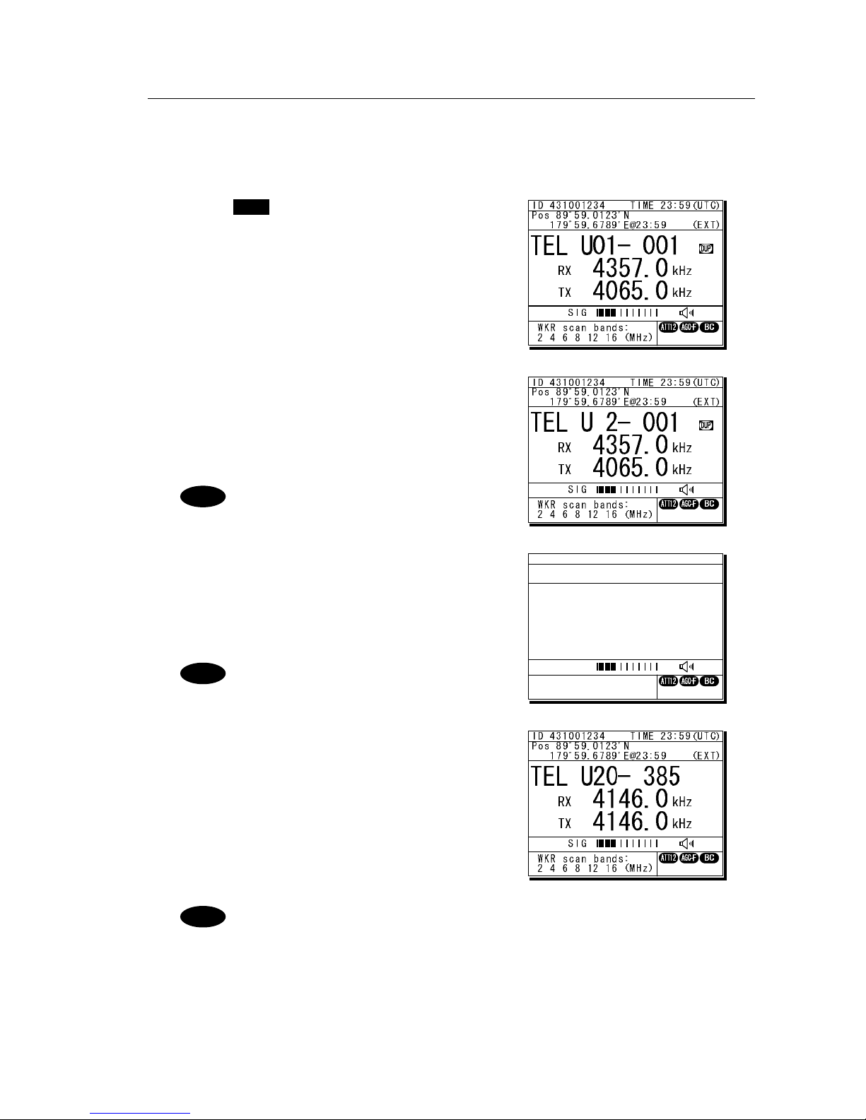
Operation
4-27
(3) Setting user channels
A total of 20 groups with 20 channels set to each group (i.e. 400 channels) can be registered on
the equipment. This section explains how to set channels that are already registered.
■ Procedure ■
1
1
1
.
.
.
Use the CH key to open the user channel
mode status display.
2
2
2
.
.
.
Pressing ENT causes the channel group
number to blink so a channel group can be
input.
Use the numeric keypad or jog dial to input the
number of a registered group.
When 2 is input using the numeric
keypad, it appears on the far right
as shown in the screen on the right.
3
3
3
.
.
.
After inputting a group number, pressing ENT
causes the channel number to blink so a user
channel can be input.
Use the numeric keypad or jog dial to input the
number of a registered channel.
When 3 is input using the numeric
keypad, it appears on the far right
as shown in the screen on the right.
4
4
4
.
.
.
Input the rest of the digits and press ENT.
¾ The input user channel frequency is
displayed and the settings are complete.
¾ The group name is displayed for 3 seconds
after the settings are done.
- Channels can be set directly in the status display by using the numeric keypad
or the jog dial without setting a channel group. After inputting with the numeric
keypad, press ENT.
- See "5.4 Registering user channels" for how to register frequencies to user
channels.
- The user channel of the telex mode is set with the menu of the data terminal,
as Tune Î Frequency list.
Note
Note
Note
TEL U20- 3
4357.0
4065.0
RX kHz
TX kHz
WKR scan bands:
2 4 6 8 12 16 (MHz)
ID 431001234 TIME 23:59(UTC)
Pos 89゚59.0123'N
179゚59.6789'E@23:59 (EXT)
SIG
Page 78

Operation
4-28
(4) Using channel lists
Besides the procedure above, user channels (except the telex mode) and ITU channels can also
be set from the channel lists (5.1 User channel list or 5.2 ITU channel list). This section explains
how to set channels that are already registered from the user channel list.
■ Procedure ■
1
1
1
.
.
.
Press the MENU key, and through
hierarchical menus, select 5. Radio
operation.
2
2
2
.
.
.
Select 1. User channel list and press ENT.
The user channel list index (group list) as
shown at right is displayed.
3
3
3
.
.
.
Select the intended channel group and press
ENT.
The user channel list as shown at right is
displayed.
4
4
4
.
.
.
Select the channel to set and press ENT.
The user channel settings are complete, the
status display is displayed.
TEL U01- 001
4357.0
4065.0
RX kHz
TX kHz
WKR scan bands:
2 4 6 8 12 16 (MHz)
ID 431001234 TIME 23:59(UTC)
Pos 89゚59.0123'N
179゚59.6789'E@23:59 (EXT)
SIG
5) Radio operation
1.User channel list
2.ITU channel list
3.Mode :TEL
4.Receiver
5.Transmitter
0.Back
5.1)User channel list (index)
No CH group name Type
01 JRC Tokyo TEL
02
03
04
05
06
07
08
Pacific ABC CW
5.1)User channel list (table)
Name: JRC Tokyo
Type: TEL
CHNo Rx[kHz] Tx[kHz] Mode
001 4357.0 4065.0 TEL
002
003
004
005
006
4360.0
4363.0
4366.0
4369.0
4372.0
4068.0
4071.0
4074.0
4077.0
4080.0
TEL
TEL
TEL
TEL
TEL
Page 79
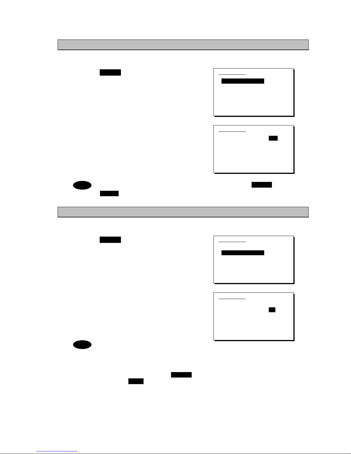
Operation
4-29
4.3.3 Setting the automatic gain control (AGC)
■ Procedure ■
1
1
1
.
.
.
Press the MENU key, and through
hierarchical menus, select 5.4 Receiver.
2
2
2
.
.
.
Select 1. Auto gain control and press ENT,
when the cursor moves to the right use the jog
dial to select Slow, Fast, or OFF.
After selecting and pressing ENT, the
settings are complete.
The same settings can be done by pressing and holding the FUNC key and the
5AGC key at the same time.
4.3.4 Setting the noise reduction (NR)
■ Procedure ■
1
1
1
.
.
.
Press the MENU key, and through
hierarchical menus, after 5.4 Receiver
appears, move the cursor to 2. Noise
reduction.
2
2
2
.
.
.
Press ENT to move the cursor to the right,
then use the jog dial to select NR1, NR2,
BC, or OFF.
After selecting and pressing ENT, the
settings are complete.
- The various settings are shown below.
・ NR1: Noise reduction (low)
・ NR2: Noise reduction (high)
・ BC: Beat canceller
- The same settings can be done by
pressing and holding the FUNC key
and the 3NR key at the same time.
- This function is invalid in the DSC mode
or the telex mode. Moreover, the beat
canceller becomes invalid in CW mode.
5.4)Receiver
1.Auto gain control :Slow
2.Noise reduction :OFF
3.Attenuation :OFF
4.Clarifier :+000Hz
5.Squelch :OFF
6.CW bandwidth :Narrow
7.Scan
0.Back
5.4)Receiver
1.Auto gain control :Fast
2.Noise reduction :OFF
3.Attenuation :OFF
4.Clarifier :+000Hz
5.Squelch :OFF
6.CW bandwidth :Narrow
7.Scan
0.Back
5.4)Receiver
1.Auto gain control :Slow
2.Noise reduction :OFF
3.Attenuation :OFF
4.Clarifier :+000Hz
5.Squelch :OFF
6.CW bandwidth :Narrow
7.Scan
0.Back
5.4)Receiver
1.Auto gain control :Slow
2.Noise reduction :NR1
3.Attenuation :OFF
4.Clarifier :+000Hz
5.Squelch :OFF
6.CW bandwidth :Narrow
7.Scan
0.Back
Note
Note
Page 80

Operation
4-30
4.3.5 Setting the attenuation (ATT)
■ Procedure ■
1
1
1
.
.
.
Press the MENU key, and through
hierarchical menus, after 5.4 Receiver
appears, move the cursor to 3.
Attenuation.
2
2
2
.
.
.
Press ENT to move the cursor to the right,
then use the jog dial to select 6dB, 12dB,
18dB, or OFF.
After selecting and pressing ENT, the
settings are complete.
The same settings can be done by pressing and holding the FUNC key and the
4ATT key at the same time.
4.3.6 Setting the clarifier
■ Procedure ■
1
1
1
.
.
.
Press the MENU key, and through
hierarchical menus, after 5.4 Receiver
appears, move the cursor to 4. Clarifier.
2
2
2
.
.
.
Press ENT to move the cursor to the right, then
use the jog dial or numeric keypad to select a
value in the range of -200 to +200 Hz.
After inputting and pressing ENT, the settings
are complete.
- When using the numeric keypad,
input "+" with the 1CLAR key and
"-" with the 2SCAN k ey.
- Pressing and holding the FUNC
key and the 1CLAR key at the
same time opens a popup screen. The
same settings can be done here.
- This function is invalid in the DSC
mode or the telex mode.
5.4)Receiver
1.Auto gain control :Slow
2.Noise reduction :OFF
3.Attenuation :OFF
4.Clarifier :+000Hz
5.Squelch :OFF
6.CW bandwidth :Narrow
7.Scan
0.Back
5.4)Receiver
1.Auto gain control :Slow
2.Noise reduction :OFF
3.Attenuation :6dB
4.Clarifier :+000Hz
5.Squelch :OFF
6.CW bandwidth :Narrow
7.Scan
0.Back
5.4)Receiver
1.Auto gain control :Slow
2.Noise reduction :OFF
3.Attenuation :OFF
4.Clarifier :+000Hz
5.Squelch :OFF
6.CW bandwidth :Narrow
7.Scan
0.Back
5.4)Receiver
1.Auto gain control :Slow
2.Noise reduction :OFF
3.Attenuation :OFF
4.Clarifier :+008Hz
5.Squelch :OFF
6.CW bandwidth :Narrow
7.Scan
0.Back
Note
Note
Page 81

Operation
4-31
4.3.7 Setting the squelch level
■ Procedure ■
1
1
1
.
.
.
Press the MENU key, and through
hierarchical menus, after 5.4 Receiver
appears, move the cursor to 5. Squelch.
2
2
2
.
.
.
Press ENT to move the cursor to the right,
then use the jog dial or numeric keypad to
input a value in the range of 000 to 100.
After inputting and pressing ENT, the settings
are complete.
- Setting the value to 000 automatically
displays it as OFF.
- This function is invalid in the DSC
mode or the telex mode.
4.3.8 Setting the CW bandwidth
■ Procedure ■
1
1
1
.
.
.
Press the MENU key, and through
hierarchical menus, after 5.4 Receiver
appears, move the cursor to 6. CW
bandwidth.
2
2
2
.
.
.
Press ENT to move the cursor to the right,
then use the jog dial to select Wide or
Narrow.
After inputting and pressing ENT, the settings
are complete.
- Setting the value to 000 automatically
displays it as OFF.
- This function is enabled in CW mode
only.
5.4)Receiver
1.Auto gain control :Slow
2.Noise reduction :OFF
3.Attenuation :OFF
4.Clarifier :+000Hz
5.Squelch :OFF
6.CW bandwidth :Narrow
7.Scan
0.Back
5.4)Receiver
1.Auto gain control :Slow
2.Noise reduction :OFF
3.Attenuation :OFF
4.Clarifier :+000Hz
5.Squelch :012
6.CW bandwidth :Narrow
7.Scan
0.Back
Note
5.4)Receiver
1.Auto gain control :Slow
2.Noise reduction :OFF
3.Attenuation :OFF
4.Clarifier :+000Hz
5.Squelch :OFF
6.CW bandwidth :Narrow
7.Scan
0.Back
5.4)Receiver
1.Auto gain control :Slow
2.Noise reduction :OFF
3.Attenuation :OFF
4.Clarifier :+000Hz
5.Squelch :OFF
6.CW bandwidth :Narrow
7.Scan
0.Back
Note
Page 82

Operation
4-32
4.3.9 Scanning the Rx frequencies
(1) Scanning of channels in TEL/DSC/CW mode
The scanning of channels in the TEL/DSC/CW mode is started with the controller.
■ Procedure ■
1
1
1
.
.
.
Press the MENU key, and through
hierarchical menus, after 5.4 Receiver
appears, move the cursor to 7. Scan.
2
2
2
.
.
.
Press ENT to confirm the selection.
The group list as shown at right is displayed.
- The previous scan can be restarted
by pressing and holding the
FUNC key and then pressing the
2SCAN key on the status display.
- If the user channel is not registered,
scan cannot be done so the screen
shown at right is not displayed.
3
3
3
.
.
.
Select the channel group to scan with the
cursor and press ENT.
The popup screen as shown at right is displayed.
If the popup screen shown at right
is displayed during scanning, Stop
appears instead of Execute.
4
4
4
.
.
.
1. Select Execute and press ENT, the screen
at right is displayed and scanning starts.
¾ To confirm the channel lists registered in a
channel group, select 2. User channel list
and press ENT.
¾ To change the scanning speed, select 3.
Scan speed (sec) and press ENT. The setting
range is 0.3 to 9.9 seconds, the same as
TEL/DSC/CW.
- Scanning can be done regardless of the squelch being set to open or close.
When pushing PTT or keying the CW keyer or when squelch is closed and
opens, scanning stops momentarily. In this case the scanning can be restarted
by pressing ENT.
- To stop scanning, press the CANCEL key.
- When scanning to receive routine DSC calls, set the scan speed to 0.3
seconds within 6 channels.
Note: If too many channels are being scanned, it may not catch the reception.
5.4)Receiver
1.Auto gain control :Slow
2.Noise reduction :OFF
3.Attenuation :OFF
4.Clarifier :+000Hz
5.Squelch :OFF
6.CW bandwidth :Narrow
7.Scan
0.Back
5.4.7)Scan
No CH group name Type
01 JRC Tokyo TEL
02
03
04
05
06
07
08
Pacific ABC CW
1. Execute
2. User channel list
3. Scan speed (sec)
TEL DSC CW
3.0 0.3 3.0
Note
Note
Note
5.4.7)Scan
No CH group name Type
01 JRC Tokyo TEL
02
03
04
05
06
07
08
Pacific ABC CW
Page 83

Operation
4-33
(2) Scanning of channels in telex mode
The scanning of channels in the telex mode is started with the data terminal.
■ Procedure ■
1
1
1
.
.
.
If displaying the message of "Press Enter key to get the access right in the NBDP
mode…" on the data terminal, press Enter key on the keyboard.
The operation of the data
terminal becomes possible in
the telex mode, except when
the controller is used.
2
2
2
.
.
.
On the main menu and the dropdown menu, select Tune Î Scanning start with Enter
key.
The registered station list is
displayed.
3
3
3
.
.
.
Select the radio station having the channel group to be scanned with the cursor, and
press Enter key.
The antenna is tuned to the
every frequency registered in
the selected radio station. The
screen at right is displayed
while tuning the antenna.
4
4
4
.
.
.
After completing the antenna tuning, scanning starts.
¾ The screen as shown at right
is displayed while scanning.
¾ When receiving a call by the
ARQ or FEC mode, scanning
stops and the communication
starts. After finishing the
communication, scanning
restarts automatically.
¾ The scanning speed can be
changed with the menu on the
regular screen, as System Î
Scan speed.
¾ When breaking the scanning,
select Tune Î
Scanning stop.
Station selection
No. Station Name ID Location F.Sig
1 Station 01 004310123 N33゚45' E138゚12' DOTDOT [Select]
2 Station 02 004311234 N37゚22' E135゚51' DOTDOT [Cancel]
3 Station 03 431012345
4
5
6
7
8
9
10 ↓
1 Station 01 004310123 N33゚45' E138゚12' DOTDOT
Page 84

Operation
4-34
4.3.10 Reducing the Tx power
■ Procedure ■
1
1
1
.
.
.
Press the MENU key, and through
hierarchical menus, select 5.5
Transmitter.
2
2
2
.
.
.
1. Select Power and press ENT to move
the cursor to the right, then use the jog dial
to select Medium or Low.
After selecting and pressing ENT, the
settings are complete.
- The same settings can be done by pressing and holding the FUNC key and
the 9 key at the same time.
- When the Tx power is reduced, MED LOW (status display) or M L
(menu screen) is displayed.
4.3.11 Setting the antenna tuning power
■ Procedure ■
On the 5.5 Transmitter menu mentioned above, select the 2. Tune power and press ENT
to move the cursor to the right, then select a value from 0 to 3 with the jog dial.
¾ The antenna tune output grows larger by about 5W step.
¾ The factory default setting is 0 (Normal).
¾ After selecting and pressing ENT, the settings are complete.
4.3.12 Setting the Auto Tune Start (ATS) function
■ Procedure ■
On the 5.5 Transmitter menu mentioned above, select the 3. Auto tune start and press
ENT to move the cursor to the right, then set to ON or OFF with the jog dial.
¾ After setting to ON, when pressing the PTT key under the following condition in TEL mode,
the antenna tuner starts tuning automatically.
- When the Tx frequency is untuned, or
- When the PA power is not turned on, i.e. the TXON is not displayed.
¾ This ATS setting data is saved in the controller. Therefore if two controllers are connected,
this function can be set to the controllers respectively.
Note
PWR
RDC
5.5)Transmitter
1.Power :High
2.Tune power :Normal
3.Auto tune start :ON
0.Back
5.5)Transmitter
1.Power :Low
2.Tune power :Normal
3.Auto tune start :ON
0.Back
Page 85

Operation
4-35
4.4 Basic DSC operations
When calling stations, the DSC is also available for a routine, safety, urgency, or a distress call.
This section explains basics of how to use the DSC to make routine calls.
4.4.1 Routine calls to an individual station
For radiotelephone or telex communication, a DSC routine call to the station to be called can be
made as follows.
■ Procedure ■
1
1
1
.
.
.
Press MENU key, and through
hierarchical menus, select 1. DSC
non-distress call.
The screen at right is an example for a call
specified the TEL mode. If required, the
communicate mode can be changed to
either of TEL/ ARQ/ FEC with the Call
type.
2
2
2
.
.
.
Select Address and press ENT to move
the cursor to the right and input the
station’s 9-digit MMSI.
3
3
3
.
.
.
To change the call frequency, select
Calling FRQ and press ENT to move the
cursor to the right, then input the Tx and
Rx frequencies with the numeric keypad.
- When 2 is input using the numeric
keypad, it appears on the far right as
shown in the screen on the right.
- Press ENT for every setting of the
Tx and Rx frequencies.
4
4
4
.
.
.
Select Working FRQ and press ENT to
move the cursor to the right and input
the working frequency (radiotelephone
frequency) with the numeric keypad.
- When 2 is input using the numeric
keypad, it appears on the far right
as shown in the screen on the
right.
- Press ENT for every setting of the
Tx and Rx frequencies.
1)DSC non-distress call
Call type :[RTN/Indv/TEL ]
Address :[ ]
Calling FRQ:[Tx 2177.0kHz]
:[Rx 2177.0kHz]
Working FRQ:[Tx . kHz]
[Rx . kHz]
[Call] [Preview] [Cancel]
1)DSC non-distress call
Call type :[RTN/Indv/TEL ]
Address :[0 ]
Calling FRQ:[Tx 2177.0kHz]
:[Rx 2177.0kHz]
Working FRQ:[Tx . kHz]
[Rx . kHz]
[Call] [Preview] [Cancel]
1)DSC non-distress call
Call type :[RTN/Indv/TEL ]
Address :[431123456]
Calling FRQ:[Tx .2kHz]
:[Rx . ]
Working FRQ:[Tx . kHz]
[Rx . kHz]
[Call] [Preview] [Cancel]
1)DSC non-distress call
Call type :[RTN/Indv/TEL ]
Address :[431123456]
Calling FRQ:[Tx 2169.0kHz]
:[Rx 2169.0kHz]
Working FRQ:[Tx .2kHz]
[Rx . kHz]
[Call] [Preview] [Cancel]
Note
Note
Page 86

Operation
4-36
5
5
5
.
.
.
When input is complete, the cursor
moves to Call.
Check the settings before making routine
calls.
Select Preview and press ENT before
calling to display the details of the
message as shown at right (bottom).
6
6
6
.
.
.
Select Call and press ENT to start the
procedure for making a routine individual
call.
¾ The sending procedure screen as shown at
right is displayed.
¾ After that the status is shown at Stage. Here
it is checking if the channel is free.
7
7
7
.
.
.
When a free channel is confirmed, the
antenna is tuned, and a DSC message is
sent.
8
8
8
.
.
.
After the DSC message is sent, wait for
acknowledgement.
9
9
9
.
.
.
Acknowledgement is received.
¾ The ALM lamp starts blinking, and the call
alarm gradually grows louder.
¾ The radiotelephone frequency is set and the
antenna is tuned automatically.
1)DSC non-distress call
Call type :[RTN/Indv/TEL ]
Address :[431123456]
Calling FRQ:[Tx 2169.0kHz]
:[Rx 2169.0kHz]
Working FRQ:[Tx 2065.0kHz]
[Rx 2065.0kHz]
[Call] [Preview] [Cancel]
Note
1)DSC non-distress call
Format :Individual
Address :431123456
Category :Routine
Self-ID :431001234
Telecommand1:Radiotelephone
Telecommand2:No information
Working FRQ :Tx 2065.0kHz
Rx 2065.0kHz
[Call] [Return] [Cancel]
ID 431001234 TIME 23:59(UTC)
Pos 89゚59.0123'N
179゚59.6789'E@23:59 (EXT)
DSC Rx: 2169.0/Tx: 2169.0kHz
Routine individual call
Stage :Waiting for CH free
Time :0.1min after calling
Call-F: 2169.0/ 2169.0kHz
Work-F: 2065.0/ 2065.0kHz
[Cancel]
WKR scan bands:
2 4 6 8 12 16 (MHz)
[Cancel]
ID 431001234 TIME 23:59(UTC)
Pos 89゚59.0123'N
179゚59.6789'E@23:59 (EXT)
DSC Rx: 2169.0/Tx: 2169.0kHz
Routine individual call
Stage :Transmitting
Time :0.3min after calling
Call-F: 2169.0/ 2169.0kHz
Work-F: 2065.0/ 2065.0kHz
[Cancel]
WKR scan bands:
2 4 6 8 12 16 (MHz)
[Cancel]
Tx
ID 431001234 TIME 23:59(UTC)
Pos 89゚59.0123'N
179゚59.6789'E@23:59 (EXT)
DSC Rx: 2169.0/Tx: 2169.0kHz
Routine individual call
Stage :Waiting for ACK
Time :0.5min after calling
Call-F: 2169.0/ 2169.0kHz
Work-F: 2065.0/ 2065.0kHz
[Cancel]
WKR scan bands:
2 4 6 8 12 16 (MHz)
[Cancel]
Page 87

Operation
4-37
1
1
1
0
0
0
.
.
.
Press the CANCEL key or ENT.
The alarm stops and the screen shown at
right is displayed.
1
1
1
1
1
1
.
.
.
Press ENT.
The status display shown at right, with
communication frequencies set, is displayed
and the routine call is completed. Start
communications using the handset.
The popup screen shown at the right
(bottom) appears if the antenna tuning
that started in step 9 above is not
finished yet.
- After completing the routine individual call where the ARQ or FEC is specified,
the telex mode is set to the equipment. Then the telex communication can be
started with the data terminal.
- If the MMSI of the coast station is input at Address, the following display and
functions are available.
¾ The initial call frequencies are TX 2189.5 kHz and Rx 2177 kHz.
Frequencies can also be selected from among international frequencies
by using the numeric keypad or the jog dial. For details, see "11.3
International DSC frequencies for routine calls".
¾ The working frequency is specified by the coast station so Working FRQ
is not displayed.
- If the objective station is unable to comply with the call, own station (caller)
may receive one of the following acknowledgements may be received. (* are
coast stations only) In this case, wait and retry the call again later, if possible,
according to the message.
No reason/ No reason.
No operator/
Operator is not present.
Congestion/ The maritime information
exchange center is congested.
*
Temp no operator/
The operator is temporarily away.
Busy/ Busy.
EQP disabled/
The equipment has been disabled.
Queue/ The call has been queued.*
Unable FRQ/
The proposed frequency cannot be used.
Barred/ The station is closed.
Unable mode/
The proposed mode cannot be used.
Note
ID 431001234 TIME 00:00(UTC)
Pos 89゚59.0123'N
179゚59.6789'E@00:00 (EXT)
TEL Rx: 2065.0/Tx: 2065.0kHz
Received routine message
Type :Individual ACK
From :431123456
Mode :Radiotelephone
Work FRQ :Tx 2065.0kHz
Rx 2065.0kHz
EOS :ACK BQ
Rx FRQ :2169.0kHz
[Continue] [Cancel]
[Continue]
TEL
2065.0
2065.0
RX kHz
TX kHz
WKR scan bands:
2 4 6 8 12 16 (MHz)
ID 431001234 TIME 00:00(UTC)
Pos 89゚59.0123'N
179゚59.6789'E@00:00 (EXT)
SIG
Note
Page 88

Operation
4-38
4.4.2 Routine calls to a group of ships
For radiotelephone or FEC broadcasting, a DSC routine call to a group of ships can be made as follows.
■ Procedure ■
1
1
1
.
.
.
Press MENU key, and through
hierarchical menus, select 1. DSC
non-distress call.
2
2
2
.
.
.
Select Call type and press ENT to move
the cursor to the right. Then use the jog
dial to select RTN/Group/TEL.
After selecting and pressing ENT, the cursor
moves to Address.
To specify the telex communication,
select RTN/Group/FEC.
3
3
3
.
.
.
Select Address and press ENT to move
the cursor to the right and input leading
zero 9-digit group ID.
4
4
4
.
.
.
To change the call frequency, select
Calling FRQ and press ENT to move the
cursor to the right, then input the Tx and
Rx frequencies with the numeric keypad.
- When 2 is input using the numeric
keypad, it appears on the far right
as shown in the screen on the
right.
- Press ENT for every setting of the
Tx and Rx frequencies.
5
5
5
.
.
.
Select Working FRQ and press ENT to
move the cursor to the right and input
the working frequency (radiotelephone
frequency) with the numeric keypad.
- When 2 is input using the numeric
keypad, it appears on the far right
as shown in the screen on the
right.
- After inputting press ENT.
1)DSC non-distress call
Call type :[RTN/Indv/TEL ]
Address :[ ]
Calling FRQ:[Tx 2177.0kHz]
:[Rx 2177.0kHz]
Working FRQ:[Tx . kHz]
[Rx . kHz]
[Call] [Preview] [Cancel]
1)DSC non-distress call
Call type :[RTN/Group/TEL ]
Address :[ ]
Calling FRQ:[Tx 2177.0kHz]
:[Rx 2177.0kHz]
Working FRQ:[Tx . kHz]
[Rx . kHz]
[Call] [Preview] [Cancel]
1)DSC non-distress call
Call type :[RTN/Group/TEL ]
Address :[043123456]
Calling FRQ:[Tx .2kHz]
:[Rx . kHz]
Working FRQ:[Tx . kHz]
[Call] [Preview] [Cancel]
1)DSC non-distress call
Call type :[RTN/Group/TEL ]
Address :[043123456]
Calling FRQ:[Tx 2169.0kHz]
:[Rx 2169.0kHz]
Working FRQ:[Tx .2kHz]
[Call] [Preview] [Cancel]
Note
Note
1)DSC non-distress call
Call type :[RTN/Group/TEL ]
Address :[0 ]
Calling FRQ:[Tx 2177.0kHz]
:[Rx 2177.0kHz]
Working FRQ:[Tx . kHz]
[Call] [Preview] [Cancel]
Note
Page 89

Operation
4-39
6
6
6
.
.
.
When input is complete, the cursor
moves to Call.
Check the settings before making a routine
group call.
Select Preview and press ENT before
calling to display the details of the
message as shown at right (bottom).
7
7
7
.
.
.
Select Call and press ENT to start the
procedure for making a routine group call.
¾ The sending procedure screen as shown at
right is displayed.
¾ After that, the status is shown at Stage. Here
it is checking if the channel is free.
8
8
8
.
.
.
When a free channel is confirmed, the
antenna is tuned, and a DSC message is
sent.
9
9
9
.
.
.
After sending a DSC message,
immediately change the communication
frequencies of the radiotelephone and
tune the antenna.
When tuning is finished, the status display
shown at right, with communication
frequencies set, is displayed and the group
call is completed. Start broadcasting using
the handset.
After completing the group call where the FEC is specified, the telex mode is set
to the equipment. Then the telex communication can be started with the data
terminal.
1)DSC non-distress call
Call type :[RTN/Group/TEL ]
Address :[043123456]
Calling FRQ:[Tx 2169.0kHz]
:[Rx 2169.0kHz]
Working FRQ:[Tx 2065.0kHz]
[Call] [Preview] [Cancel]
Note
1)DSC non-distress call
Format :Group
Address :043123456
Category :Routine
Self-ID :431001234
Telecommand1:Radiotelephone
Telecommand2:No information
Working FRQ :Tx 2065.0kHz
EOS :EOS
[Call] [Return] [Cancel]
TEL
2169.0
2065.0
RX kHz
TX kHz
WKR scan bands:
2 4 6 8 12 16 (MHz)
ID 431001234 TIME 00:00(UTC)
Pos 89゚59.0123'N
179゚59.6789'E@00:00 (EXT)
SIG
Note
Page 90

Operation
4-40
4.4.3 Receiving routine calls
When receiving a DSC call from a coast or ship station, the message will be displayed
immediately on the screen. After that, perform the following procedures as appropriate.
(1) Receiving an individual call (Type: Radiotelephone or Telex)
■ Procedure ■
1
1
1
.
.
.
The screen at right is displayed, and the
ALM lamp blinks and the alarm grows
louder gradually.
The example message contains the following
information.
- Message type: Individual call
- Caller's MMSI: 123456789
- Communication mode: Radiotelephone
- Work frequency: Tx 2065.0 kHz
Rx 2065.0 kHz
- Sequence process: ACK RQ
- Reception frequency: 2177.0 kHz
2
2
2
.
.
.
Press the CANCEL key or ENT to stop
the alarm, and the screen at right is
displayed.
3
3
3
.
.
.
If the call can be accepted, select Accept
and press ENT.
¾ The acknowledgement procedure screen as
shown at right is displayed.
¾ After that, the status is shown at Stage. Here
it is checking if the channel is free.
¾ See the following notes for information about
the other items (Unable/NewCH/Cancel) in
the handling menu.
4
4
4
.
.
.
When a free channel is confirmed, the
antenna is tuned, and an acknowledgement
message is sent.
ID 431001234 TIME 23:59(UTC)
Pos 89゚59.0123'N
179゚59.6789'E@23:59 (EXT)
DSC Rx: 2177.0/Tx: 2177.0kHz
Routine individual ACK
Stage :Waiting for CH free
Time :0.1min after calling
Call-F: 2177.0/ 2177.0kHz
Work-F: 2065.0/ 2065.0kHz
[Cancel]
WKR scan bands:
2 4 6 8 12 16 (MHz)
[Cancel]
Page 91

Operation
4-41
5
5
5
.
.
.
After sending an acknowledgement
message, changes the working frequency
and tunes the antenna.
6
6
6
.
.
.
When acknowledgement is finished, the
status display is displayed.
Start communications using the handset.
- After completing the DSC call sequence specifying the ARQ or FEC, the telex
mode is set to the equipment. Then the telex communication can be started
with the data terminal.
- When Unable (unable to comply) is selected in the received message handling
menu, the following popup screen opens. Select a reason to insert in the
message.
No reason/ No reason.
Temp no oper/
The operator is temporarily away.
Busy/ Busy.
EQP disabled/
The equipment has been disabled.
Barred/ The station is closed.
Unable FRQ/
The proposed frequency cannot be used.
No oper/
Operator is not present.
Unable mode/
The proposed mode cannot be used.
- When New CH (change working frequency) is selected in the received message
handling menu, the following popup screen opens. Enter an appropriate
working frequency.
- When Cancel is selected in the received message handling menu, the previous
screen reappears.
Note
TEL
2065.0
2065.0
RX kHz
TX kHz
WKR scan bands:
2 4 6 8 12 16 (MHz)
ID 431001234 TIME 23:59(UTC)
Pos 89゚59.0123'N
179゚59.6789'E@23:59 (EXT)
SIG
ID 431001234 TIME 23:59(UTC)
Pos 89゚59.0123'N
179゚59.6789'E@23:59 (EXT)
TEL Rx: 2065.0/Tx: 2065.0kHz
Routine individual ACK
Stage :Acknowledged
Time :0.8min after calling
Call-F: 2177.0/ 2177.0kHz
Work-F: 2065.0/ 2065.0kHz
[Cancel]
WKR scan bands:
2 4 6 8 12 16 (MHz)
[Cancel]
Tx
T
Page 92

Operation
4-42
(2) Receiving an individual call (Type: Polling)
■ Procedure ■
1
1
1
.
.
.
The screen at right is displayed, and the
ALM lamp blinks and the alarm grows
louder gradually.
The example message contains the following
information.
- Message type: Individual call
- Caller's MMSI: 001234567
- Purpose of call: Polling
- Sequence process: ACK RQ
- Reception frequency: 2177.0 kHz
2
2
2
.
.
.
Press the CANCEL key or ENT to stop the
alarm, and the screen at right is displayed.
When the Auto ACK is set to on and
the status display is displayed, the
acknowledgement is automatically
sent upon receiving a call, without the
notification shown at right.
3
3
3
.
.
.
Select Send ACK and press ENT to send
the acknowledgement.
¾ The acknowledgement procedure screen as
shown at right is displayed.
¾ After that, the status is shown at Stage. Here
it is checking if the channel is free.
4
4
4
.
.
.
When a free channel is confirmed, the
antenna is tuned to the calling frequency
and an acknowledgement is sent.
5
5
5
.
.
.
Once the acknowledgement is sent, the
status display is displayed.
The polling call is now complete because
there is no communication using such as the
radiotelephone.
Note
ID 431001234 TIME 23:59(UTC)
Pos 89゚59.0123'N
179゚59.6789'E@23:59 (EXT)
DSC Rx: 2177.0/Tx: 2177.0kHz
Routine polling ACK
Stage :Transmitting
Time :0.1min after calling
Call-F: 2177.0/ 2177.0kHz
[Cancel]
WKR scan bands:
2 4 6 8 12 16 (MHz)
[Cancel]
Tx
ID 431001234 TIME 23:59(UTC)
Pos 89゚59.0123'N
179゚59.6789'E@23:59 (EXT)
DSC Rx: 2177.0/Tx: 2177.0kHz
Received routine message
Type :Individual call
From :001234567
Intent :Polling
EOS :ACK RQ
Rx FRQ :2177.0kHz
[Send ACK] [Cancel]
[Send ACK]
Page 93

Operation
4-43
(3) Receiving a group call
■ Procedure ■
1
1
1
.
.
.
The screen at right is displayed, and the
ALM lamp blinks and the alarm grows
louder gradually.
The example message contains the following
information.
- Message type: Group call
- Caller's MMSI: 123456789
- Communication mode: Radiotelephone
- Work frequency: Rx 2065.0 kHz
- Sequence process: End of sequence
- Reception frequency: 2177.0 kHz
2
2
2
.
.
.
Press the CANCEL key or ENT to stop
the alarm, and the screen at right is
displayed.
3
3
3
.
.
.
If possible to listen to the broadcast, select
Accept and press ENT to set the working
channel.
After receiving the group call where the FEC is specified and accepting it, the
telex mode is set to the equipment. Then the telex communication can be started
with the data terminal.
ID 431001234 TIME 23:59(UTC)
Pos 89゚59.0123'N
179゚59.6789'E@23:59 (EXT)
DSC Rx: 2177.0/Tx: 2177.0kHz
Received routine message
Type :Group call
From :123456789
Mode :Radiotelephone
Work FRQ :Rx 2065.0kHz
EOS :EOS
Rx FRQ :2177.0kHz
[Accept] [Cancel]
[Accept]
Note
Page 94

Operation
4-44
4.5 Emergency calls (DSC safety/urgency/distress calls)
In emergency, the DSC is available for safety, urgency, or distress calls. For safety and urgency
calls, either individual calls or area calls is selectable for the type of call. For distress calls,
enabled to send either after entering the nature of distress or frequency, or without entering
anything. In both cases, pressing the DISTRESS key is required to send the distress call.
4.5.1 Safety calls
44..55..11..11
Individual calls
For radiotelephone or telex communication, a DSC safety call can be made as follows.
■ Procedure ■
1
1
1
.
.
.
Press MENU key, and through
hierarchical menus, select 1. DSC
non-distress call.
2
2
2
.
.
.
Select Call type and press ENT to move
the cursor to the right. Then use the jog
dial to select SAF/Indv/TEL.
To specify the telex communication,
select SAF/Indv/ARQ or
SAF/Indv/FEC.
3
3
3
.
.
.
Press ENT.
The text displayed in Calling FRQ and
Working FRQ changes as shown to the right,
and the cursor moves to Address.
4
4
4
.
.
.
Select Address and press ENT to move
the cursor to the right and input the
station’s 9-digit MMSI.
1)DSC non-distress call
Call type :[RTN/Indv/TEL ]
Address :[ ]
Calling FRQ:[Tx 2177.0kHz]
:[Rx 2177.0kHz]
Working FRQ:[Tx . kHz]
[Rx . kHz]
[Call] [Preview] [Cancel]
1)DSC non-distress call
Call type :[SAF/Indv/TEL ]
Address :[ ]
Calling FRQ:[Tx 2177.0kHz]
:[Rx 2177.0kHz]
Working FRQ:[Tx . kHz]
[Rx . kHz]
[Call] [Preview] [Cancel]
1)DSC non-distress call
Call type :[SAF/Indv/TEL ]
Address :[ ]
Calling FRQ:[ 2187.5kHz]
Working FRQ:[ 2182.0kHz]
[Call] [Preview] [Cancel]
1)DSC non-distress call
Call type :[SAF/Indv/TEL ]
Address :[0 ]
Calling FRQ:[ 2187.5kHz]
Working FRQ:[ 2182.0kHz]
[Call] [Preview] [Cancel]
Note
Page 95

Operation
4-45
5
5
5
.
.
.
To change the call frequency, select
Calling FRQ and press ENT to move the
cursor to the right. Then select the
distress and safety frequencies using the
jog dial.
- The numeric keypad can also be used.
- For information on distress and
safety calls, See "11.1 Frequencies
for distress and safety calls".
6
6
6
.
.
.
Press ENT.
The work frequency of the same band as the
input Calling FRQ is automatically set in
Working FRQ and the cursor moves to
Working FRQ.
7
7
7
.
.
.
Move the cursor to Call and press ENT to
start the procedure for making an
individual safety call.
¾ The sending procedure screen as shown at
right is displayed.
¾ After that, the status is shown at Stage. DSC
messages are sent immediately upon
antenna tuning because a free channel
(excluding test calls) is not confirmed for a
safety category.
The following procedure is the same as in "4.4.1 Routine calls to an individual
station".
Note
Note
ID 431001234 TIME 23:59(UTC)
Pos 89゚59.0123'N
179゚59.6789'E@23:59 (EXT)
DSC Rx: 4207.5/Tx: 4207.5kHz
Safety individual call
Stage :Transmitting
Time :0.3min after calling
Call-F: 4207.5/ 4207.5kHz
Work-F: 4125.0/ 4125.0kHz
[Cancel]
WKR scan bands:
2 4 6 8 12 16 (MHz)
[Cancel]
Tx
1)DSC non-distress call
Call type :[SAF/Indv/TEL ]
Address :[431123456]
Calling FRQ:[ 4207.5kHz]
Working FRQ:[ 2182.0kHz]
[Call] [Preview] [Cancel]
1)DSC non-distress call
Call type :[SAF/Indv/TEL ]
Address :[431123456]
Calling FRQ:[ 4207.5kHz]
Working FRQ:[ 4125.0kHz]
[Call] [Preview] [Cancel]
Page 96

Operation
4-46
44..55..11..22
Area calls
For radiotelephone or FEC broadcasting, a DSC safety area call can be made as follows.
■ Procedure ■
1
1
1
.
.
.
Press MENU key, and through
hierarchical menus, select 1. DSC
non-distress call.
2
2
2
.
.
.
Select Call type and press ENT to move
the cursor to the right. Then use the jog
dial to select SAF/Area/TEL.
To specify the telex communication,
select SAF/Area/FEC.
3
3
3
.
.
.
Press ENT.
The display changes as shown to the right
and the cursor moves to Area form.
4
4
4
.
.
.
Set the area to call.
Enter as below according to the Area form
settings.
- When Center&rad
・ Enter the center point of the area in
Center.
・ Enter the radius of the area in Radius.
- When Corner&dev (shown at right)
・ Enter the northwest corner of the area in
Corner.
・ Enter the south and north/east and west
deviation in a range from 00 to 99 in
Deviation.
5
5
5
.
.
.
To change the call frequency, select
Calling FRQ and press ENT to move the
cursor to the right. Then select the
distress and safety frequencies using the
jog dial.
- The numeric keypad can also be
used.
- For information on distress and
safety calls, See "11.1 Frequencies
for distress and safety calls".
Note
1)DSC non-distress call
Call type :[RTN/Indv/TEL ]
Address :[ ]
Calling FRQ:[Tx 2177.0kHz]
:[Rx 2177.0kHz]
Working FRQ:[Tx . kHz]
[Rx . kHz]
[Call] [Preview] [Cancel]
1)DSC non-distress call
Call type :[SAF/Area/TEL ]
Address :[ ]
Calling FRQ:[Tx 2177.0kHz]
:[Rx 2177.0kHz]
Working FRQ:[Tx . kHz]
[Rx . kHz]
[Call] [Preview] [Cancel]
1)DSC non-distress call
Call type :[SAF/Area/TEL ]
Area form :[Center&rad]
- Center :[89゚N179゚E]
- Radius :[0500NM]
Calling FRQ:[ 2187.5kHz]
Working FRQ:[ 2182.0kHz]
[Call] [Preview] [Cancel]
1)DSC non-distress call
Call type :[SAF/Area/TEL ]
Area form :[Corner&dev]
- Corner :[ ゚N ゚E]
- Deviation:[ ゚/ ゚]
Calling FRQ:[ 2187.5kHz]
Working FRQ:[ 2182.0kHz]
[Call] [Preview] [Cancel]
1)DSC non-distress call
Call type :[SAF/Area/TEL ]
Area form :[Center&rad]
- Center :[89゚N179゚E]
- Radius :[0500NM]
Calling FRQ:[ 4207.5kHz]
Working FRQ:[ 2182.0kHz]
[Call] [Preview] [Cancel]
Note
Page 97

Operation
4-47
6
6
6
.
.
.
Press ENT.
The work frequency of the same band as the
input Calling FRQ is automatically set in
Working FRQ and the cursor moves to
Working FRQ.
7
7
7
.
.
.
Move the cursor to Call and press ENT to
start the procedure for making an area
safety call.
¾ The sending procedure screen as shown at
right is displayed.
¾ After that, the status is shown at Stage. DSC
messages are sent immediately upon
antenna tuning because a free channel
(excluding test calls) is not confirmed for a
safety category.
8
8
8
.
.
.
After sending a DSC message, immediately
change the communication frequencies of
the radiotelephone and tune the antennas.
Once tuning is complete, the status display
shown at right is displayed with
communication frequencies set and the area
call is completed. Start broadcasting using
the handset.
After completing the area call where the FEC is specified, the telex mode is set to
the equipment. Then the telex communication can be started with the data
terminal.
1)DSC non-distress call
Call type :[SAF/Area/TEL ]
Area form :[Center&rad]
- Center :[89゚N179゚E]
- Radius :[0500NM]
Calling FRQ:[ 4207.5kHz]
Working FRQ:[ 4125.0kHz]
[Call] [Preview] [Cancel]
TEL
4207.5
4125.0
RX kHz
TX kHz
WKR scan bands:
2 4 6 8 12 16 (MHz)
ID 431001234 TIME 23:59(UTC)
Pos 89゚59.0123'N
179゚59.6789'E@23:59 (EXT)
SIG
Note
Page 98

Operation
4-48
44..55..11..33
Other features of safety calls (position request/test)
Use safety calls to request the position information to a station or to make a DSC test call.
(1) Position request call
■ Procedure ■
1
1
1
.
.
.
Press MENU key, and through
hierarchical menus, select 1. DSC
non-distress call.
2
2
2
.
.
.
Select Call type and press ENT to move
the cursor to the right. Then use the jog
dial to select SAF/Indv/PosRQ.
3
3
3
.
.
.
Press ENT.
The display changes as shown to the right
and the cursor moves to Address.
4
4
4
.
.
.
Select Address and press ENT to move
the cursor to the right and input the
station’s 9-digit MMSI.
5
5
5
.
.
.
To change the call frequency, select
Calling FRQ and press ENT to move the
cursor to the right. Then select the
distress and safety frequencies using the
jog dial and press ENT.
- The numeric keypad can also be used.
- For information on distress and
safety calls, See "11.1 Frequencies
for distress and safety calls".
- After input is complete, check the
details of the message before
sending it using Preview.
Note
1)DSC non-distress call
Call type :[RTN/Indv/TEL ]
Address :[ ]
Calling FRQ:[Tx 2177.0kHz]
:[Rx 2177.0kHz]
Working FRQ:[Tx . kHz]
[Rx . kHz]
[Call] [Preview] [Cancel]
1)DSC non-distress call
Call type :[SAF/Indv/PosRQ]
Address :[ ]
Calling FRQ:[Tx 2177.0kHz]
:[Rx 2177.0kHz]
Working FRQ:[Tx . kHz]
[Rx . kHz]
[Call] [Preview] [Cancel]
1)DSC non-distress call
Call type :[SAF/Indv/PosRQ]
Address :[ ]
Calling FRQ:[ 2187.5kHz]
[Call] [Preview] [Cancel]
1)DSC non-distress call
Call type :[SAF/Indv/PosRQ]
Address :[0 ]
Calling FRQ:[ 2187.5kHz]
[Call] [Preview] [Cancel]
1)DSC non-distress call
Call type :[SAF/Indv/PosRQ]
Address :[431123456]
Calling FRQ:[ 4207.5kHz]
[Call] [Preview] [Cancel]
Page 99

Operation
4-49
6
6
6
.
.
.
Select Call and press ENT to start the
procedure for making a position request
call.
¾ The sending procedure screen as shown at
right is displayed.
¾ After that, the status is shown at Stage. DSC
messages are sent immediately upon
antenna tuning because a free channel
(excluding test calls) is not confirmed for a
safety category.
7
7
7
.
.
.
After the DSC message is sent, wait for
acknowledgement.
8
8
8
.
.
.
When an acknowledgement is received,
the message such as the one at right
with the position information of the
station is displayed.
¾ The ALM lamp starts blinking, and the call
alarm gradually grows louder.
¾ Press either the CANCEL key or ENT to
silence the alarm and display Close button.
After checking the position of the other
station in the acknowledgement, press ENT
in Close to show the status display.
¾ The position request process is now
complete because there is no communication
using such as the radiotelephone.
Even if the equipment is functioning properly, Unknown may be displayed for the
time and position depending on the condition of the station, and replies may be
not be received depending on the status of radio wave propagation.
ID 431001234 TIME 23:59(UTC)
Pos 89゚59.0123'N
179゚59.6789'E@23:59 (EXT)
DSC Rx: 4207.5/Tx: 4207.5kHz
Safety position request call
Stage :Transmitting
Time :0.1min after calling
Call-F: 4207.5/ 4207.5kHz
[Cancel]
WKR scan bands:
2 4 6 8 12 16 (MHz)
[Cancel]
Tx
Press CANCEL to silence alarm.
ID 431001234 TIME 23:59(UTC)
Pos 89゚59.0123'N
179゚59.6789'E@23:59 (EXT)
DSC Rx: 4207.5/Tx: 4207.5kHz
Received safety message
Type :Individual ACK
From :431123456
Intent :Ship position
Position :90゚00'N
180゚00'E
UTC of pos:12:34
EOS :ACK BQ
Rx FRQ :4207.5kHz
Note
Page 100

Operation
4-50
(2) Test call
■ Procedure ■
1
1
1
.
.
.
Press MENU key, and through
hierarchical menus, select 1. DSC
non-distress call.
2
2
2
.
.
.
Select Call type and press ENT to move
the cursor to the right. Then use the jog
dial to select SAF/Indv/Test.
3
3
3
.
.
.
Press ENT.
The display changes as shown to the right
and the cursor moves to Address.
4
4
4
.
.
.
Select Address and press ENT to move
the cursor to the right and input the other
stations 9-digit MMSI.
5
5
5
.
.
.
To change the call frequency, select
Calling FRQ and press ENT to move the
cursor to the right. Then select the
distress and safety frequencies using the
jog dial and press ENT.
- The numeric keypad can also be used.
- For information on distress and
safety calls, See "11.1 Frequencies
for distress and safety calls".
- After input is complete, check the
details of the message before
sending it using Preview.
Note
1)DSC non-distress call
Call type :[RTN/Indv/TEL ]
Address :[ ]
Calling FRQ:[Tx 2177.0kHz]
:[Rx 2177.0kHz]
Working FRQ:[Tx . kHz]
[Rx . kHz]
[Call] [Preview] [Cancel]
1)DSC non-distress call
Call type :[SAF/Indv/Test ]
Address :[ ]
Calling FRQ:[Tx 2177.0kHz]
:[Rx 2177.0kHz]
Working FRQ:[Tx . kHz]
[Rx . kHz]
[Call] [Preview] [Cancel]
1)DSC non-distress call
Call type :[SAF/Indv/Test ]
Address :[0 ]
Calling FRQ:[ 2187.5kHz]
[Call] [Preview] [Cancel]
1)DSC non-distress call
Call type :[SAF/Indv/Test ]
Address :[431123456]
Calling FRQ:[ 4207.5kHz]
[Call] [Preview] [Cancel]
1)DSC non-distress call
Call type :[SAF/Indv/Test ]
Address :[ ]
Calling FRQ:[ 2187.5kHz]
[Call] [Preview] [Cancel]
 Loading...