


MARINE RADAR
EQUIPMENT
INSTRUCTION
MANUAL

9900
LCD
1087/1089
NKE-1079/1075ANKE-1079/1075ANKE-1079/1075A
NKE-1079/1075A


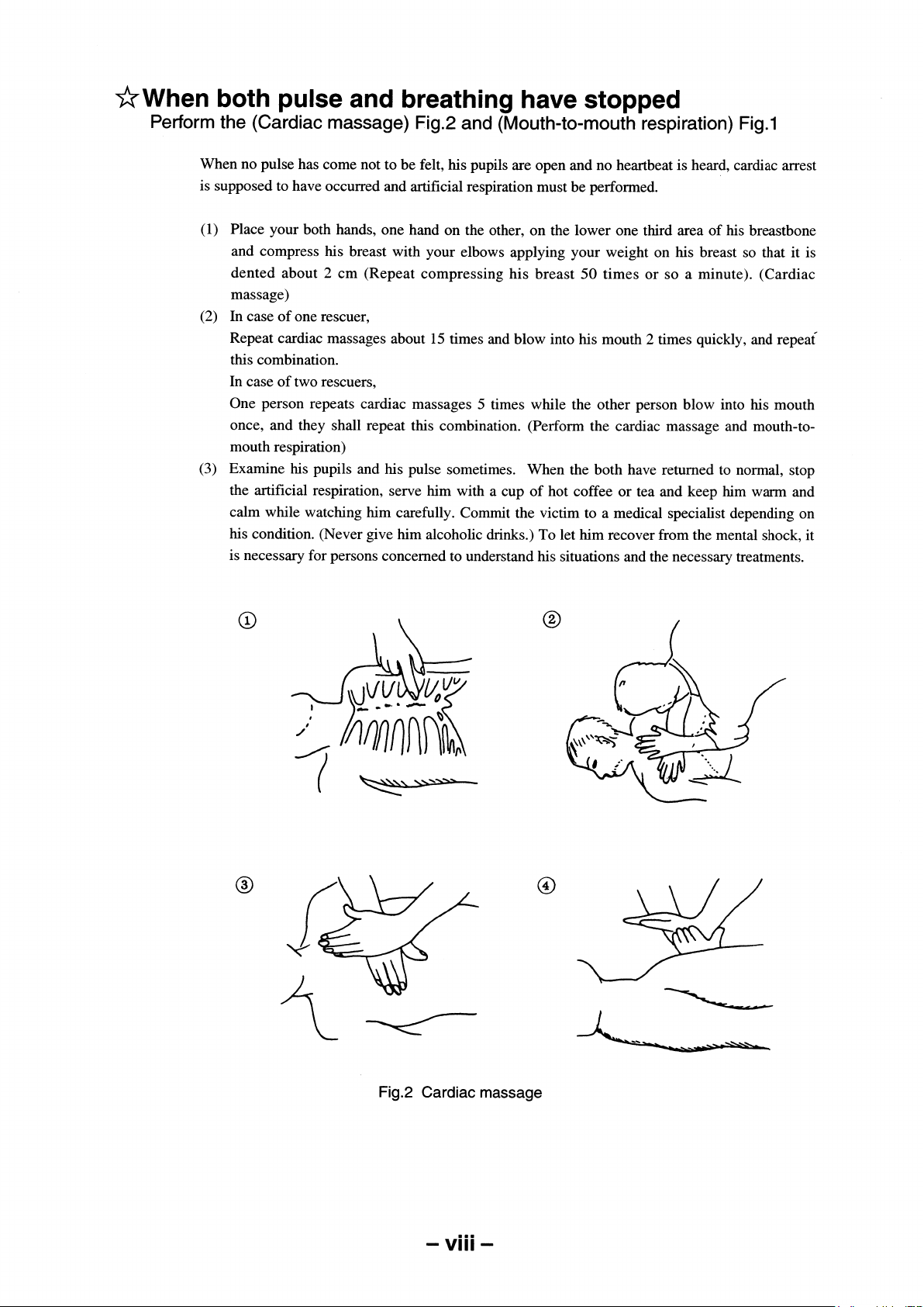
Then, wipe his mouth so that foaming mucus does not accumulate inside.

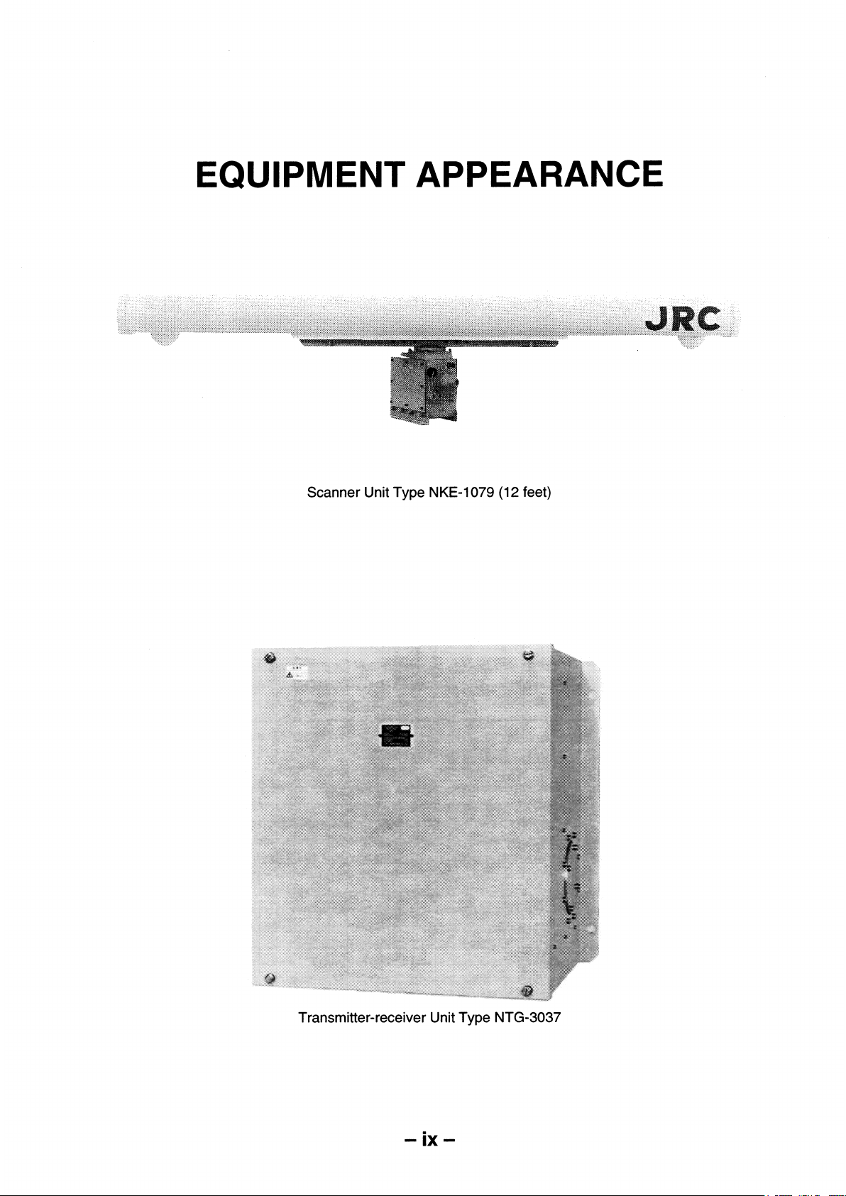
Transmitter-receiver Unit Type NTG-3037/3037A
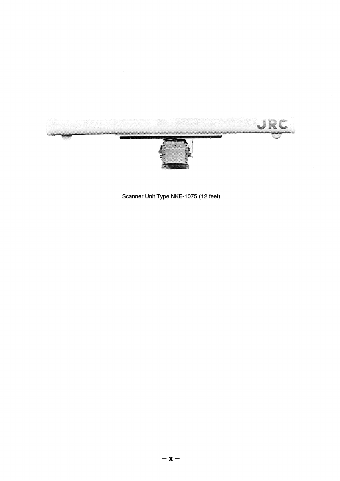
Scanner Unit Type NKE-1075/1075A (12 Feet)
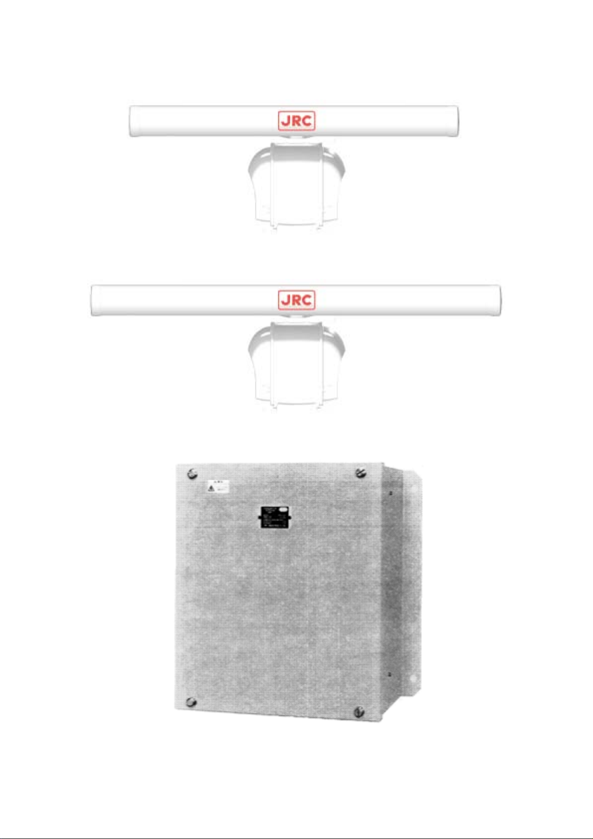
ScannerUnitTypeNKE‑1089‑7(7Feet)
ScannerUnitTypeNKE‑1089‑9(9Feet)
Transmitter‑receiverUnitType
―xi―
NTG‑3028
ScannerUnitTypeNKE‑1087‑6(6Feet)
ScannerUnitTypeNKE‑1087‑9(9Feet)
―xii―

Display Unit Type NCD-4263(Self-standing Type)
−xiii−
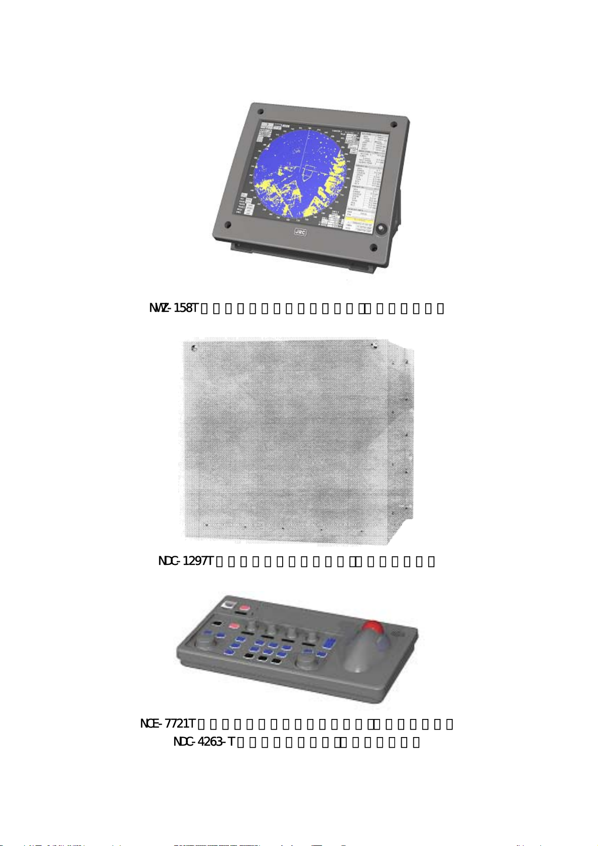
Monitor Unit Type NWZ-158T (Desktop Type) (Option)
Control Unit Type NDC-1279T (Desktop Type) (Optyon)
Keyboard Unit Type NCE-7721T (Desktop Type) (Option)
Display Unit Type NCD-4263T (Desktop Type) (Option)
NWZ‑158T 形モニタ部ユニット(卓上形)(オプション)
NDC‑1297T 形制御ユニット(卓上形)(オプション)
NCE‑7721T 形キーボードユニット(卓上形)(オプション)
NDC‑4263‑T 形指示機(卓上形)(オプション)
―xiv―

CONTENTS
PREFACE ....................................................................................... i
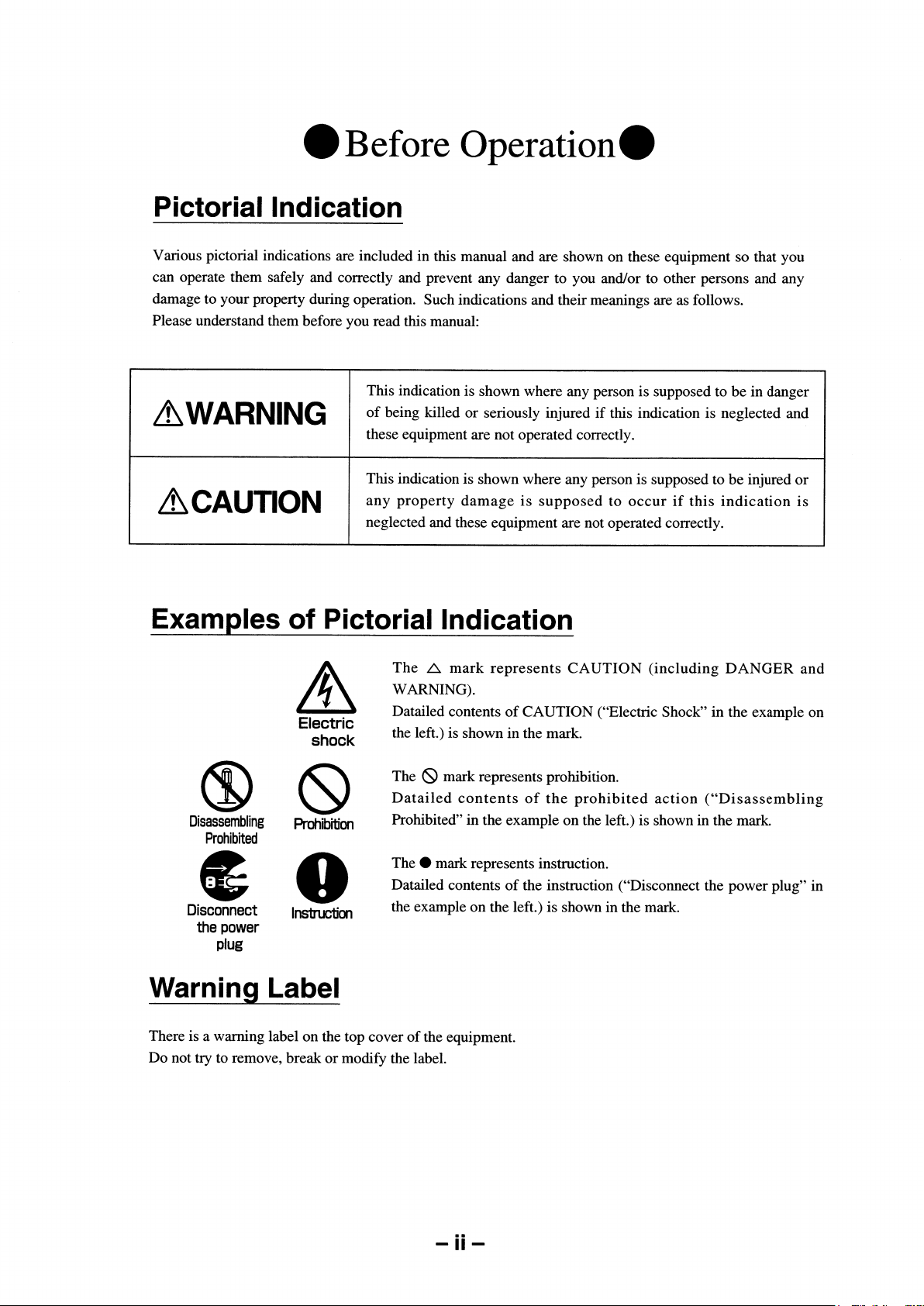
Before Operation .......................................................................... ii
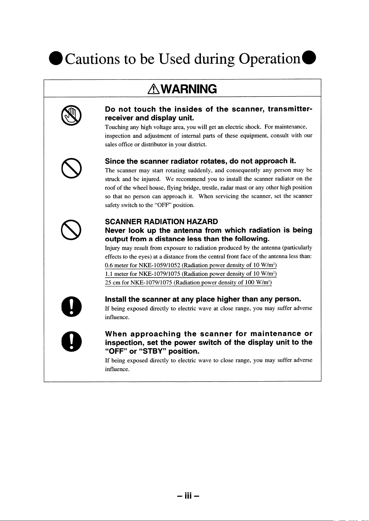
Cautions to be Used during Operation ................................... iii
PRECAUTIONS BEFORE OPERATION
■ Cautions for high voltage .................................................................v
■ What to do in case of electric shock ..............................................v
FIRST-AID TREATMENTS
☆ First-aid treatments ..........................................................................vi
☆ When pulse is beating but breathing has stopped ....................vii
☆ When both pulse and breathing have stopped .........................viii
EQUIPMENT APPEARANCE ..................................................... ix
GLOSSARY ................................................................................ xxi
1. GENERAL AND EQUIPMENT COMPOSITION
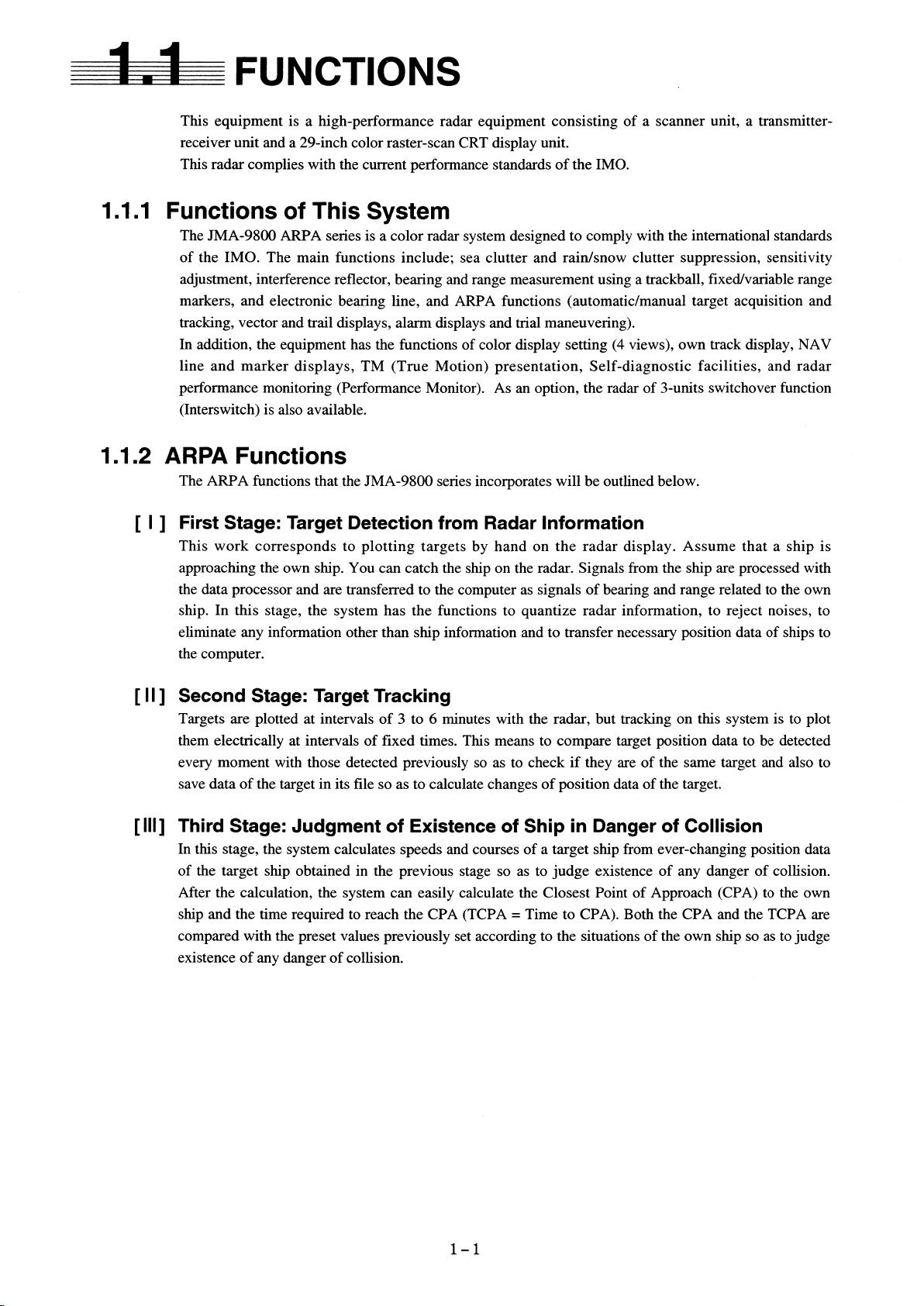
1.1 FUNCTIONS ....................................................................................... 1-1
1.2 FEATURES ......................................................................................... 1-3
1.3 CONFIGURATION .............................................................................1-5
1.4 EXTERIOR DRAWING ...................................................................... 1-7
1.5 GENERAL SYSTEM DIAGRAM ....................................................1-20
1.6 COLLISION AVOIDANCE ...............................................................1-27
2. NAME AND FUNCTION OF CONTROL PANEL
SWITCHES AND FUNCTION OF
SOFTWARE BUTTONS
2.1 NAME AND FUNCTION OF CONTROL PANEL SWITCHES ....... 2-1
2.2 FUNCTION OF SOFTWARE BUTTONS ......................................... 2-7
- xv -

3. BASIC OPERATION
3.1 FLOW OF OPERATION .................................................................... 3-1
■ Power ON and Start the System ..................................................3-2
■ Observe and Adjust Video ........................................................... 3-4
■ Tuning Operations ......................................................................... 3-6
■ Acquire and Measurement Data ..................................................3-7
■ End the Operation and Stop the System ................................... 3-7
3.2 MENU COPOSITION .........................................................................3-8
3.3 PREPARATION ................................................................................ 3-11
■ Tuning[TUNE] ............................................................................... 3-11
■ Sensitivity Control [GAIN] .......................................................... 3-11
■ Display Brilliance Control ...........................................................3-12
■ Contrast Control [BRILL VIDEO] ...............................................3-12
■ Sea Clutter Suppression [RAIN] ................................................3-13
■ Brilliance Control .........................................................................3-13
■ Day/Night Mode Selection [DAY/NIGHT] ..................................3-21
■ Color Setting [COLOR] ...............................................................3-22
3.4 BASIC OPERATIONS .....................................................................3-34
■ Move Cross Cursor Mark [+] by Trackball ............................... 3-34
■ Methods for Setting Menu Items with the Trackball ..............3-35
■ Use EBLs(Electronic Bearing Lines) ........................................ 3-41
■ Set Floating EBL .......................................................................... 3-43
■ Set Floating EBL .......................................................................... 3-45
■ Select Range [RANGE] ...............................................................3-47
■ Set Maximum Range ...................................................................3-47
■ Select Pulse Length ....................................................................3-48
■ Select Bearing Display Mode [AZI MODE] ..............................3-49
■ Cancel Ship's Heading Line [HL OFF] ......................................3-49
■ Cancel All Display Items Except HL and Cross Cursor
Mark [+] [DATA OFF] ....................................................................3-49
■ Display PI (Parallel Index Lines) [PI] ......................................... 3-50
■ Move Own Ship's Display Position [OFF CENTER] ...............3-53
■ Display Other Ship's Trails [TRAILS] ........................................3-54
■ Display Own Ship's Tracks and Own Symbols[OWN SHIP].. 3-55
■ Marking [MARK] ...........................................................................3-58
■ Display Range Rings [RANGE RINGS] ....................................3-59
■ Display Variable Range Markers [VRM1/VRM2] ..................... 3-59
■ Set Guard Zone [GUARD ZONE] ............................................... 3-61
■ Reset Alarm Buzzer [ALARM ACK] .......................................... 3-63
■ Set Alarm Sound Level ............................................................... 3-63
- xvi -

■ Check Operation Status [TEST] ................................................3-64
■ FUNCTION ....................................................................................3-73
■ Expand Targets ............................................................................ 3-74
■ Display Processed Videos .........................................................3-75
■ Reduce Radar Interference ........................................................3-76
■ Personal Information ..................................................................3-77
■ Display of Navigational Information .........................................3-80
■ Function of USER Switch / OPTION Switch ............................3-96
■ Operation of Performance Monitor ...........................................3-97
■ EBL Maneuvering ......................................................................3-103
4. MEASUREMENT OF RANGE AND BEARING
■ Measurement by Trackball ........................................................... 4-1
■ Measurement by Range Rings .................................................... 4-2
■ Measurement by EBLs and VRMs .............................................. 4-2
■ Measurement by between Two Optional Points ....................... 4-4
5. OPERATION OF ARPA AND AIS
Using ARPA .............................................................................................. 5-1
5.1 INITIAL SETTING ............................................................................... 5-2
■ Setting Collision Decision Criteria : SAFE LIMIT .....................5-2
■ Automatic Setting Mode (System Start) ....................................5-4
■ Setting Range Scale : RANGE SCALE ....................................... 5-4
■ Setting Own Ship's Speed ............................................................5-5
5.2 DISPLAY MODE SETTING ............................................................... 5-7
■ Setting Motion Display Mode [TM/RM] ......................................5-7
■ Setting Bearing Display Mode [AZI MODE] ............................... 5-7
5.3 TARGET ID No. DISPLAY ................................................................. 5-8
5.4 TARGET ACQUISITION .................................................................... 5-9
■ Automatic Acquisition [AUTO] .................................................. 5-11
■ Manual Acquisition [MANUAL] ................................................. 5-12
■ Use of Automatic and Manual
Acquisition Modes [ACQ AUTO] [ACQ MANUAL] ............... 5-13
5.5 ARPA DATA DISPLAY ..................................................................... 5-13
■ Display of Vectors ........................................................................ 5-13
■ Display of Past Positions [PAST POSN] ..................................5-16
5.6 DATA DISPLAY ................................................................................5-18
■ Types of Data Display ................................................................. 5-18
■ Method of Displaying Target Data [TGT DATA] ......................5-19
- xvii -

■ Cancellation of Displaying Target Data [TGT DATA] .............5-19
5.7 ALARM DISPLAY .............................................................................5-20
■ Dangerous Target Alarm: CPA/TCPA .......................................5-20
■ Guard Zone Alarm [GUARD ZONE] ..........................................5-21
■ Lost Target Alarm [LOST TARGET] ..........................................5-22
■ System Function Alarm [ARPA(DATA)] ................................... 5-23
■ Gyro Set Alarm [SET GYRO] .....................................................5-23
5.8 TRIAL MANEUVERING ..................................................................5-24
■ Trial Maneuvering in the True Vector Mode .............................5-24
■ Trial Maneuvering in the Relative Vector Mode ......................5-25
■ Using the TRIAL Function .......................................................... 5-26
5.9 DELETING UNWANTED TARGETS ..............................................5-27
■ Deleting Targets ...........................................................................5-27
5.10 ARPA SETTING .............................................................................5-29
■ Simulation .....................................................................................5-30
■ Gate Size ....................................................................................... 5-32
■ Test Video ......................................................................................5-34
6. TRUE AND FALSE ECHOES ON DISPLAY
■ Radar Wave with the Horizon ...................................................... 6-1
■ Strength of Reflection from the Target .......................................6-3
■ Sea Clutters .................................................................................... 6-3
■ False Echoes .................................................................................. 6-3
■ Display of Radar Transponder (SART) ...................................... 6-6
7. MAINTENANCE
7.1 ROUTINE MAINTENANCE ...............................................................7-1
7.2 MAINTENANCE ON EACH UNIT .................................................... 7-2
■ Scanner NKE-1079/10750/1089/1087 .......................................... 7-2
■ Transmitter-receiver Unit NTG-3037/3037A/3028 ..................... 7-4
■ Display Unit NCD-4263 ................................................................. 7-5
■ Coaxial Cable JMA-9933-SA ........................................................7-5
■ Wave Guide JMA-9923-7XA/9XA ................................................ 7-6
8. COUNTERMEASURES FOR
TORUBLE AND ADJUSTMENT
8.1 FUNCTION CHECK ...........................................................................8-1
■ Function Check on Test Menu ..................................................... 8-2
■ List of Alarms and other Indications ........................................ 8-10
- xviii -

8.2 TROUBLESHOOTING ....................................................................8-13
8.3 COUNTERMEASURES TO TROUBLE ........................................ 8-14
8.4 REPLACEMNT OF MAJOR PARTS .............................................. 8-20
■ Replacement of Magnetron (V1/V201) .....................................8-21
■ Replacement to TRHPL
(A202/A203)(JMA-9933-SA/9932-SA) ....................................... 8-21
■ Replacement of Diode Limiter(A203)
(JMA-9923-7XA/9XA, JMA-9922-6XA/9XA)................................ 8-20
■ Replacement of PIN Attenuator(A302)
(JMA-9923-7XA/9XA, JMA-9922-6XA/9XA)............................... 8-21
■ Replacement of the Liquid-Crystal Monitor ............................ 8-22
8.5 ADJUSTMENT .................................................................................8-23
■ Tuning Adjustment ......................................................................8-24
■ Bearing Adjustment ....................................................................8-25
■ Range Adjustment .......................................................................8-26
■ Antenna Height Adjustment ...................................................... 8-27
■ Vector Constant ........................................................................... 8-28
■ Quantization Level .......................................................................8-29
■ Adjustment of NSK Unit to Gyro Compass and Log .............8-30
■ Main Bang Suppression Adjustment .......................................8-32
8.6 SETTING ...........................................................................................8-34
■ True Bearing Setting ...................................................................8-34
■ Ship Speed Setting ...................................................................... 8-35
■ Navigation Equipment Setting ..................................................8-37
■ Current Correction(SET/DRIFT) Setting ...................................8-38
■ Time/Day Display Setting ........................................................... 8-40
■ Adjustment of Performance Monitor(NJU-63/64) ...................8-42
■ Adjustment of Inter switch........................................................... 8-44
9. AFTER-SALES SERVICE
■ When you Request for Repair ..................................................... 9-1
■ Recommended Maintenance ....................................................... 9-1
■ Radar Failure Check List .............................................................. 9-2
- xix -

10. DISPOSAL
10.1 DISPOSAL OF THE UNIT ............................................................. 10-1
10.2 DISPOSAL OF USED BATTERIES .............................................10-1
10.3 DISPOSAL OF USED MAGNETRON .........................................10-1
11. SPECIFICATION
11.1 JMA-9933-SA TYPE RADAR ....................................................... 11-1
11.2 JMA-9932-SA TYPE RADAR ....................................................... 11-2
11.3 JMA-9923-7XA/9XA TYPE RADAR ............................................. 11-3
11.4 JMA-9922-6XA/9XA TYPE RADAR ............................................. 11-4
11.5 SCANNER(NKE-1079) .................................................................. 11-5
11.6 SCANNER(NKE-1075) .................................................................. 11-6
11.7 SCANNER(NKE-1089-7/9............................................................... 11-7
11.8 SCANNER(NKE-1087-6/9) ............................................................ 11-8
11.9 TRANSMITTER-RECEIVER UNIT(NTG-3037) ........................... 11-9
11.10 TRANSMITTER-RECEIVER UNIT(NTH-3028) ....................... 11-10
11.11 DISPLAY UNIT(NCD-4263) ....................................................... 11-11
11.12 ARPA ...........................................................................................11-12
11.13 PERFORMANCE MONITOR(NJU-63) .................................... 11-13
11.10 PERFORMANCE MONITOR(NJU-64) .................................... 11-13
APPENDIX
JMA-9900 ARPA Series Radar System Composition ...................... A-1
JMA-9900 ARPA Series Radar System Circuit Block ....................... A-2
Fig.101 Block Diagram of Radar, Type JMA-9933-SA and JMA-9923-7XA/9XA
Fig.102 Block Diagram of Radar, Type JMA-9932-SA and JMA-9922-6XA/9XA
Fig.103 Terminal Board Connection Diagram of Radar, Type JMA-9933-SA
(SELF STANDING TYPE)
Fig.104 Terminal Board Connection Diagram of Radar, Type JMA-9933-SA
(DESK TOP TYPE)
Fig.105 Terminal Board Connection Diagram of Radar, Type JMA-9932-SA
(SELF STANDING TYPE )
Fig.106 Terminal Board Connection Diagram of Radar, Type JMA-9932-SA
(DESK TOP TYPE )
Fig.107 Terminal Board Connection Diagram of Radar, Type JMA-9923-7XA/9XA
(SELF STANDING TYPE AC220V 3φ)
Fig.108 Terminal Board Connection Diagram of Radar, Type JMA-9923-7XA/9XA
(SELF STANDING TYPE AC220V 1φ AC100V 1φ)
Fig.109 Terminal Board Connection Diagram of Radar, Type JMA-9923-7XA/9XA
(DESK TOP TYPE AC220V 3φ)
Fig.110 Terminal Board Connection Diagram of Radar, Type JMA-9923-7XA/9XA
(DESK TOP TYPE AC220V 1φ AC100V 1φ)
- xx -

Fig.111 Terminal Board Connection Diagram of Radar, Type JMA-9922-6XA/9XA
(SELF STANDING TYPE AC220V 3φ)
Fig.112 Terminal Board Connection Diagram of Radar, Type JMA-9922-6XA/9XA
(SELF STANDING TYPE AC220V 1φ AC100V 1φ)
Fig.113 Terminal Board Connection Diagram of Radar, Type JMA-9922-6XA/9XA
(DESK TOP TYPE AC220V 3φ)
Fig.114 Terminal Board Connection Diagram of Radar, Type JMA-9922-6XA/9XA
(DESK TOP TYPE AC220V 1φ AC100V 1φ)
Fig.115 Primary Power Supply lock Diagram of Radar, Type JMA-9933-SA
Fig.116 Primary Power Supply lock Diagram of Radar, Type JMA-9932-SA
Fig.117 Primary Power Supply lock Diagram of Radar, Type JMA-9923-7XA/9XA
Fig.118 Primary Power Supply lock Diagram of Radar, Type JMA-9922-6XA/9XA
Fig.119 Internal Connection Diagram of Scanner Unit, Type NKE-1079
Fig.120 Internal Connection Diagram of Scanner Unit, Type NKE-1079-D
Fig.121 Internal Connection Diagram of Scanner Unit,
Type NKE-1075/1075A (100V AC,1-phase)
Fig.122 Internal Connection Diagram of Scanner Unit,
Type NKE-1075/1075A (230V AC,3-phase)
Fig.123 Internal Connection Diagram of Scanner Unit,
Type NKE-1075/1075A (230V AC,1-phase)
Fig.124 Internal Connection Diagram of Scanner Unit, Type NKE-1089-7/9 (1-phase)
Fig.125 Internal Connection Diagram of Scanner Unit, Type NKE-1089-7/9 (3-phase)
Fig.126 Internal Connection Diagram of Scanner Unit, Type NKE-1087-6/9 (1-phase)
Fig.127 Internal Connection Diagram of Scanner Unit, Type NKE-1087-6/9 (3-phase)
Fig.128 Internal Connection Diagram of Transmitter-receiver Unit, Type NTG-3037/3037A
Fig.129 Internal Connection Diagram of Transmitter-receiver Unit, Type NTG-3028
Fig.130 Internal Connection Diagram of Display Unit, Type NCD-4263
Fig.131 Internal Connection Diagram of CRT Monitor of Display Unit, Type NCD-4263
Fig.132 Internal Connection Diagram of Power Supply of Display Unit, Type NCD-4263
Fig.133 List of NSK and LOG Select Switches of Display Unit, Type NCD-4263
Fig.134 Setting Table of Speed LOG Select Switches of Display Unit, Type NCD-4263
Fig.135 Setting Table of Gyro Compass and Gyro Select Switches of
Display Unit, Type NCD-4263
Fig.136 Terminal Board Connection Diagram of 2-unit Interswitchesystem, Type NQE-3141N
Fig.137 Terminal Board Connection Diagram of 3-unit Interswitches
System, Type NQE-3141N
Fig.138 Internal Connection Diagram of Interswitch, Type NQE-3141N
- xxi -
Rejection
Use as a temporary marker


9900
9900
In addition, a radar switching function ( interswitch ) can be added to switch between two, four or eight
eight radar units. However, in order to this function for four or eight units, an external switching box is
necessary.
23.1 inch color raster-scan LCD display unit

LCD

the soft button on a screen and screen menu.

9900

9933
9923
9932
9923
9923
9922
9933
9922
9922
9922
9923
9932
9933
1087-9
1087-6
1089-9
1089-7
1079
NTG-3037A
3028
4263
230
100/230V
230
NTG-3037
-1075 (*)
-1075A (*)
NKE
NKE

230
230

1075/1075A
1079
1089-7
1089-9
1087-6
1087-9
3037/3037A
3028
4263
158T
1279T
7721T

Fig.1.1 EXTERIOR DRAWING OF
SCANNER UNIT,TYPE NKE-1079
1―8

Fig.1.2 EXTERIOR DRAWING OF
SCANNER UNIT,TYPE NKE-1075
1―9

Fig.1.3 EXTERIOR DRAWING OF
SCANNER UNIT,TYPE NKE-1089-7
1―10

Fig.1.4 EXTERIOR DRAWING OF
SCANNER UNIT,TYPE NKE-1089-9
1―11

Fig.1.5 EXTERIOR DRAWING OF
SCANNER UNIT,TYPE NKE-1087-6
1―12

1―13
Fig.1.6 EXTERIOR DRAWING OF
SCANNER UNIT,TYPE NKE-1087-9
1―13

Fig.1.7 EXTERIOR DRAWING OF
TRANSMITTER-RECEIVER UNIT,TYPE NTG-3037/3037A
1―14

Fig.1.8 EXTERIOR DRAWING OF
TRANSMITTER-RECEIVER UNIT,TYPE NTG-3028
1―15

Fig.1.9 EXTERIOR DRAWING OF DISPLAY UNIT,
TYPE NCD-4263(SELF-STANDING TYPE)
1―16

Fig.1.10 EXTERIOR DRAWING OF MONITOR UNIT,
TYPE NWZ-158 (DESKTOP TYPE)(OPTION)
1―17

Fig.1.11 EXTERIOR DRAWING OF CONTROL UNIT,
TYPE NDC-1279 (DESKTOP TYPE)(OPTION)
1―18

Fig.1.12 EXTERIOR DRAWING OF KEYBOARD UNIT,
TYPE NCE-7721 (DESKTOP TYPE)(OPTION)
1―19

Fig.1.13 GENERAL SYSTEM DIAGRAM OF RADAR,TYPE JMA-9933-SA
Fig.1.14 GENERAL SYSTEM DIAGRAM OF RADAR,TYPE JMA-9932-SA
Fig.1.15 GENERAL SYSTEM DIAGRAM OF RADAR,TYPE JMA-9923-7XA
Fig.1.16 GENERAL SYSTEM DIAGRAM OF RADAR,TYPE JMA-9923-9XA
Fig.1.17 GENERAL SYSTEM DIAGRAM OF RADAR,TYPE JMA-9922-6XA
Fig.1.18 GENERAL SYSTEM DIAGRAM OF RADAR,TYPE JMA-9922-9XA

●●●●●●●●●●●●●●●●●●●●●● ● ● ● ● ● ● ● ● ● ●● ● ● ● ● ● ●
9933
3038
4 2 6 3
AC100/230V
50/60Hz, 1
AC230V
50/60Hz, 3
1kVA
Φ
Φ
1
SHIP'SMAIN
AC100/110V
50/60Hz,1φ,200W
14CORESCOMPOSITECABLE
H-2695110056
MAX30MTφ23(JRCSUPPLY)
250V-DPYCYS-1.25
CIRCUITBREAKER
SK-32C
(5A)
OPTION)
14CORESCOMPOSITECABLE
H-2695110056
MAX35MTφ23(JRCSUPPLY)
NKE-1079SCANNERUNT
COAXIALCABLE
HF-20D(JRCSUPPLY)
NTG-3037TRANSMITTER-RECEIVERUNIT
Note:
Note:
NCD-4263DISPLAYUNIT
GYRO
LOG
GPS
Eliminating the interference on frequencies used for marine communications and
Eliminating the interference on frequencies used for marine communications and
navigation due to operation of the radar.
navigation due to operation of the radar.
All cables of the radar are to be run away from the cables of radio equipment.
All cables of the radar are to be run away from the cables of radio equipment.
(Ex. Radiotelephone. Communications receiver and direction finder. etc)
(Ex. Radiotelephone. Communications receiver and direction finder. etc)
Especially inter-wiring cables between scanner unit and display unit of the radar
Especially inter-wiring cables between scanner unit and display unit of the radar
250V-MPYCYS-5
250V-DPYCYS-1.25
250V-TTYCS-1
660V-TPYCYS-5.5
SHIP'SMAIN
AC110/220V
60Hz,1φ
AC220V
60Hz,3φ
800VA
should not run parallel with the cables of radio equipment.
should not run parallel with the cables of radio equipment.
1−21
Fig.1.13 GENERAL SYSTEM DIAGRAM OF
RADAR, TYPE JMA-9933-SA

●●●●●●●●●●●●●●●●●●●●●● ● ● ● ● ● ● ● ● ● ●● ● ● ● ● ● ●
9932
4 2 6 3
AC100/230V
50/60Hz, 1
AC230V
50/60Hz, 3
1kVA
Φ
Φ
NKE-1075 SCANNERUNIT
250V-DPYCYS-1.25
1
SHIP'SMAIN
AC100/110V
50/60Hz,1φ,100W
CIRCUITBREAKER
SK-32C
(5A)
(OPTION)
14CORESCOMPOSITECABLE
H-2695110056
MAX65MTφ23(JRCSAPPLY)
NCD-4263 DISPLAYUNIT
Note:
250V-MPYCYS-5
GIRO
LOG
GPS
250V-DPYCYS-1.25
250V-TTYCS-1
660V-TPYCYS-5.5
SHIP'SMAIN
AC100/110/220/230V
60Hz,1φ
AC220/230V
60Hz,3φ
800VA
Eliminating the interference on frequencies used for marine communications and
navigation due to operation of the radar.
All cables of the radar are to be run away from the cables of radio equipment.
(Ex. Radiotelephone. Communications receiver and direction finder. etc)
Especially inter-wiring cables between scanner unit and display unit of the radar
should not run parallel with the cables of radio equipment.
Fig.1.14 GENERAL SYSTEM DIAGRAM OF
RADAR, TYPE
JMA-9932-SA
1−22

1
9923
4 2 6 3
- 1 0 8 9 - 7
3028
AC100/230V
50/60Hz, 1
AC230V
50/60Hz, 3
800VA
ΦΦΦ
●●●●●●●●●●●●●●●●●●●●●● ● ● ● ● ● ● ● ● ● ●● ● ● ● ● ● ●
NKE-1089-7SCANNERUNIT
250V-DPYCYS-1.25
SHIP'SMAIN
AC100/110V
50/60Hz,1φ,100W
CIRCUTBREAKER
SK-32C
(5A)
(OPTION)
FLEXIBLEWAVEGUIDE
FR-9(JRCSAPPLY)
14CORESCOMPOSITECABLE
H-2695110056
MAX35MTφ23(JRCSAPPLY)
14CORESCOMPOSITECABLE
H-2695110056
MAX30MTφ23(JRCSAPPLY)
NTG-3028TRANSMITTER-RECEIVERUNIT
NCD-4263DISPAYUNIT
GYRO
LOG
GPS
250V-MPYCYS-5
250V-DPYCYS-1.25
250V-TTYCS-1
660V-TPYCYS-5.5
SHIP'SMAIN
AC100/110/220/230V
60Hz,1φ
AC220/230V
60Hz,3φ
600VA
Note:
Eliminating the interference on frequencies used for marine communications and
navigation due to operation of the radar.
All cables of the radar are to be run away from the cables of radio equipment.
(Ex. Radiotelephone. Communications receiver and direction finder. etc)
Especially inter-wiring cables between scanner unit and display unit of the radar
should not run parallel with the cables of radio equipment.
1−23
Fig.1.15 GENERAL SYSTEM DIAGRAM OF
RADAR, TYPE
JMA-9923-7XA

●●●●●●●●●●●●●●●●●●●●●● ● ● ● ● ● ● ● ● ● ●● ● ● ● ● ● ●
9923
AC100/230V
50/60Hz, 1
AC230V
50/60Hz, 3
800VA
Φ
Φ
- 1 0 8 9 - 9
4 2 6 3
3028
AC100/230V
NKE-1089-9SCANNERUNIT
250V-DPYCYS-1.25
1
SHIP'SMAIN
AC100/110V
50/60Hz,1φ,100W
CIRCUITBREAKER
SK-32C
(5A)
(OPTION)
FLEXIBLEWAVEGUIDE
FR-9(JRCSAPPLY)
14CORESCOMPOSITECABLE
H-2695110056
MAX35MTφ23(JRCSAPPLY)
14CORESCOMPOSITECABLE
H-2695110056
MAX30MTφ23(JRCSAPPLY)
NTG-3028TRANSMITTER-RECEIVERUNIT
NCD-4263DISPLAYUNIT
GYRO
LOG
GPS
250V-MPYCYS-5
250V-DPYCYS-1.25
250V-TTYCS-1
660V-TPYCYS-5.5
SHIP'SMAIN
AC100/110/220/230V
60Hz,1φ
AC220/230V
60Hz,3φ
600VA
Note:
Eliminating the interference on frequencies used for marine communications and
navigation due to operation of the radar.
All cables of the radar are to be run away from the cables of radio equipment.
(Ex. Radiotelephone. Communications receiver and direction finder. etc)
Especially inter-wiring cables between scanner unit and display unit of the radar
should not run parallel with the cables of radio equipment.
1−24
Fig.1.16 GENERAL SYSTEM DIAGRAM OF
RADAR, TYPE JMA-9923-9XA

1
9922
- 1 0 8 7 - 6
4 2 6 3
AC100/230V
50/60Hz, 1
AC230V
50/60Hz, 3
800VA
Φ
Φ
●●●●●●●●●●●●●●●●●●●●●● ● ● ● ● ● ● ● ● ● ●● ● ● ● ● ● ●
NKE-1087-6 SCANNERUNIT
250V-DPYCYS-1.25
SHIP'SMAIN
AC100/110V
50/60Hz,1φ,100W
CIRCUITBREAKER
SK-32C
(5A)
(OPTION)
14CORESCOMPOSITECABLE
H-2695110056
MAX65MTφ23(JRCSAPPLY)
NCD-4263 DISPLAYUNIT
Note:
GYRO
250V-MPYCYS-5
250V-DPYCYS-1.25
LOG
250V-TTYCS-1
GPS
660V-TPYCYS-5.5
SHIP'SMAIN
AC100/110/220/230V
60Hz,1φ
AC220/230V
60Hz,3φ
600VA
Eliminating the interference on frequencies used for marine communications and
navigation due to operation of the radar.
All cables of the radar are to be run away from the cables of radio equipment.
(Ex. Radiotelephone. Communications receiver and direction finder. etc)
Especially inter-wiring cables between scanner unit and display unit of the radar
should not run parallel with the cables of radio equipment.
Fig.1.17 GENERAL SYSTEM DIAGRAM OF
RADAR, TYPE JMA-9922-6XA
1−25

●●●●●●●●●●●●●●●●●●●●●● ● ● ● ● ● ● ● ● ● ●● ● ● ● ● ● ●
9922
- 1 0 8 7 - 9
4 2 6 3
AC100/230V
50/60Hz, 1
AC220V
50/60Hz, 3
800VA
Φ
Φ
NKE-1087-9 SCANNERUNIT
250V-DPYCYS-1.25
1
SHIP'SMAIN
AC100/110V
50/60Hz,1φ,100W
CIRCUITBREAKER
SK-32C
(5A)
(OPTION)
14CORESCOMPOSITECABLE
H-2695110056
MAX65MTφ23(JRCSAPPLY)
NCD-4263 DISPLAYUNIT
Note:
GYRO
250V-MPYCYS-5
250V-DPYCYS-1.25
LOG
250V-TTYCS-1
GPS
660V-TPYCYS-5.5
SHIP'SMAIN
AC100/110/220/230V
60Hz,1φ
AC220/230V
60Hz,3φ
600VA
Eliminating the interference on frequencies used for marine communications and
navigation due to operation of the radar.
All cables of the radar are to be run away from the cables of radio equipment.
(Ex. Radiotelephone. Communications receiver and direction finder. etc)
Especially inter-wiring cables between scanner unit and display unit of the radar
should not run parallel with the cables of radio equipment.
Fig.1.18 GENERAL SYSTEM DIAGRAM OF
RADAR, TYPE JMA-9922-9XA
1−26


SECTION 2
NAME AND FUNCTION OF
CONTROL PANEL SWITCHES
AND FUNCTION OF
SOFTWARE BUTTONS
NAME AND FUNCTION OF CONTROL PANEL SWITCHES.......................2-1
FUNCTION OF SOFTWARE BUTTONS.......................................................2-6


2
● ● ● ● ● ● ● ● ● ● ● ● ● ● ● ● ● ● ● ● ● ● ● ● ● ● ● ● ● ● ● ● ● ● ● ● ● ● ●
NAME AND FUNCTION OF CONTROL PANEL SWITCHES
Screen Display Example
e
n
)
)
)
g
t
g
e
o
e
n
o
i
t
t
f
t
i
a
r
e
c
i
d
s
d
t
)
r
)
)
e
s
)
t
i
d
a
x
n
a
w
u
-
o
g
1
r
o
(
l
g
G
s
s
r
i
i
O
x
o
x
L
a
s
a
/
-
n
-
L
2
e
2
s
(
A
(
U
G
W
d
N
e
X
X
e
A
A
A
p
2
2
M
S
/
/
(
k
r
a
)
g
F
m
n
F
i
r
r
O
o
s
/
A
r
N
u
P
c
O
C
(
f
o
g
n
i
r
a
e
g
b
n
k
i
r
r
e
a
a
u
e
r
m
b
T
r
o
e
s
v
i
r
t
u
d
a
c
l
e
t
e
f
a
R
o
r
e
l
p
l
o
a
b
)
n
k
S
o
c
i
P
t
a
r
c
G
t
n
h
u
y
t
k
i
F
b
r
a
w
(
m
n
r
o
i
o
t
s
i
r
s
r
u
o
e
t
C
p
n
e
c
f
f
O
2
M
R
V
k
1
c
L
a
B
r
t
E
s
'
n
p
i
w
h
s
O
1
M
l
i
R
a
r
V
t
t
s
e
'
g
p
r
i
a
h
s
T
t
D
I
e
g
p
r
i
a
h
T
s
l
o
b
n
o
r
m
i
o
t
y
t
a
s
c
c
i
e
p
i
d
v
h
n
i
s
p
i
t
a
h
t
e
s
a
g
t
r
d
a
e
n
g
i
T
r
a
T
n
i
d
e
t
a
)
c
i
g
d
n
i
n
i
n
g
u
n
i
L
t
n
l
A
u
a
U
t
u
N
n
o
t
A
a
u
h
M
M
t
A
(
d
i
w
r
o
e
t
g
s
l
a
n
i
u
c
i
n
P
d
u
n
T
i
r
o
t
a
c
i
d
n
i
g
n
i
r
a
e
B
s
t
k
°
0
0
.
.
5
5
4
1
2
D
N
G
B
A
T
D
S
E
G
E
S
D
P
O
H
S
m
)
n
°
1
4
.
1
7
5
3
.
E
1
4
R
I
U
C
A
E
U
R
T
(
R
O
S
R
0
U
3
0
C
0
2
0
0
1
0
0
0
0
0
5
3
0
4
3
0
3
3
O
T
U
A
P
S
P
+
U
6
1
N
M
-
R
l
)
e
l
a
M
a
v
/
r
c
R
)
e
(
s
t
M
n
n
e
i
T
o
g
(
i
r
n
t
e
n
a
o
k
o
R
i
r
M
t
a
o
e
m
v
M
i
t
e
e
a
g
l
u
n
e
r
a
R
T
R
t
n
n
n
i
e
e
e
r
r
t
r
r
a
u
u
D
C
C
'
'
6
s
s
t
k
°
2
1
.
.
R
9
9
7
E
2
T
A
W
N
A
G
G
M
O
O
C
S
'
5
°
7
6
.
1
.
1
2
3
5
゜
2
5
3
N
L
E
R
0
4
0
0
0
t
3
0
0
k
:
°
0
0
4
0
0
.
0
.
0
3
T
E
S
'
3
7
7
.
3
4
゜
9
3
1
E
.
0
1
.
5
0
9
8
3
4
1
°
°
/
5
9
3
3
3
1
0
N
E
/
3
0
0
2
T
F
N
N
I
A
W
R
U
M
D
O
R
F
A
E
F
P
T
O
C
F
N
L
F
E
H
0
C
O
6
0
0
5
0
1
0
2
3
0
1
3
T
I
D
M
N
S
A
N
B
A
-
R
X
T
r
o
t
a
c
i
d
n
i
/
t
r
i
y
o
b
t
m
a
d
s
c
n
n
i
a
a
d
t
r
n
i
S
T
0
0
3
y
c
r
e
o
u
t
q
a
e
c
)
r
i
f
y
d
l
-
h
n
n
i
2
c
o
t
f
i
d
r
o
n
w
e
a
s
e
n
r
b
s
n
e
u
a
t
S
c
n
/
n
I
i
s
X
(
p
e
u
p
m
t
i
u
e
t
t
s
e
r
s
o
A
t
A
P
c
e
P
C
V
T
C
n
n
i
i
m
m
0
6
1
D
N
G
B
T
m
A
n
T
S
5
R
.
1
O
A
T
T
P
I
C
R
M
E
I
A
V
L
G
N
I
0
7
R
0
0
9
2
n
r
e
t
t
a
p
n
o
i
t
c
e
n
n
o
c
d
n
d
(
(
k
D
I
(
g
e
)
)
n
e
p
d
i
s
i
n
r
h
o
a
s
z
e
t
b
d
e
r
e
g
a
r
u
u
r
a
T
T
G
n
i
m
°
2
4
2
1
o
6
N
2
1
T
E
N
N
D
I
S
O
T
Z
O
E
P
D
G
T
R
R
S
A
G
A
A
R
U
T
P
B
G
0
8
0
n
)
)
i
r
e
)
m
u
e
n
(
o
p
s
c
e
g
e
e
n
u
u
a
r
r
T
T
T
m
n
°
5
1
.
8
3
2
E
S
E
R
G
U
N
O
A
C
R
0
9
0
n
i
m
m
m
(
n
m
n
(
(
(
A
T
R
A
P
C
C
P
C
B
B
C
T
n
n
s
i
i
m
m
t
n
n
m
m
k
3
4
.
.
9
0
D
E
E
P
S
C
1
4
.
o
1
N
8
5
2
-
D
I
T
E
G
A
R
R
T
A
P
A
P
C
C
C
T
T
B
B
0
0
1
6
3
2
0
0
8
7
2
2
n
o
i
t
i
s
o
p
s
'
p
i
h
s
n
w
O
0
6
2
l
L
o
H
b
m
y
s
p
i
h
s
y
t
e
f
a
S
2
a
t
a
d
p
i
h
s
t
e
g
r
a
T
n
n
s
i
m
n
°
°
8
9
4
.
7
4
3
2
3
E
S
E
R
G
U
G
N
O
R
A
B
C
R
P
A
0
1
M
1
i
m
m
t
n
n
m
m
k
2
0
6
.
.
.
9
1
8
8
9
5
D
A
E
R
A
P
E
P
C
P
C
S
C
T
B
m
T
0
F
I
0
H
1
H
T
S
P
E
0
D
2
1
4
5
0
4
2
T
0
5
2
F
s
'
e
o
r
p
h
i
t
y
h
r
g
s
e
e
t
k
h
n
r
a
t
i
a
c
w
i
w
o
d
m
r
n
f
i
g
e
o
n
k
i
o
r
g
t
d
a
n
a
i
d
r
m
e
e
a
h
g
y
e
a
n
s
b
l
i
'
p
d
p
e
i
s
a
i
u
h
e
r
d
S
(
t
h
R
I
T
C
C
A
A
D
e
c
n
)
e
d
r
e
e
t
f
c
r
e
e
t
n
r
n
n
i
o
t
o
r
c
c
a
e
l
d
s
f
a
s
e
a
R
r
p
m
o
c
m
o
a
i
t
n
a
e
e
m
d
m
r
o
a
o
f
c
n
n
l
i
e
a
n
y
n
i
l
a
o
l
s
p
V
r
s
i
A
e
P
N
D
K
T
S
C
E
A
T
O
O
F
Z
Y
N
G
I
K
O
Y
T
A
L
P
S
I
D
T
V
A
C
N
B
3
C
L
1
N
E
Y
U
N
A
F
A
D
P
0
3
1
0
4
1
0
0
0
2
2
2
2
2
2
0
3
2
N
A
I
E
A
S
G
n
r
o
i
e
t
s
t
s
u
e
l
r
c
p
p
w
u
o
s
n
O
r
s
T
e
/
t
U
n
t
i
A
u
a
l
)
R
c
A
a
E
e
S
S
(
m
r
a
I
l
A
P
o
N
U
N
E
N
I
M
P
C
O
m
m
n
n
°
°
0
0
0
0
.
.
7
2
7
5
.
.
3
3
2
1
0
1
T
T
1
2
1
2
L
L
M
M
B
B
R
R
E
E
V
V
0
5
1
0
6
1
0
7
1
0
8
1
0
9
1
0
0
2
F
F
0
0
0
1
1
1
O
2
2
2
H
N
E
T
1
n
i
C
n
i
m
O
m
5
.
R
3
0
P
S
K
L
C
C
I
N
O
I
A
A
R
A
R
R
P
R
T
T
l
k
)
a
c
N
v
I
a
r
r
A
t
e
t
R
s
(
n
'
i
p
n
i
y
o
h
r
i
s
o
L
s
s
A
n
m
e
e
U
r
w
p
m
N
O
p
A
u
s
M
n
o
i
t
a
c
i
d
n
n
o
i
i
t
g
a
n
c
i
i
r
d
a
n
i
e
b
m
e
r
v
a
i
l
t
A
a
l
e
R
:
R
n
o
i
t
a
c
i
d
n
i
g
n
i
r
a
e
b
e
u
r
T
:
)
T
d
e
t
c
e
l
e
s
1
M
e
R
g
e
n
V
g
a
r
n
e
l
a
b
2
r
a
M
r
1
e
R
M
p
g
V
R
n
O
i
(
V
r
a
e
b
2
L
g
n
B
i
r
E
a
e
b
1
L
B
E
k
r
a
m
r
o
s
r
u
C
e
n
o
z
d
r
a
u
G
2
L
B
e
E
d
o
m
e
c
n
a
h
n
e
o
e
d
i
v
r
a
d
a
R
e
d
o
m
l
g
k
a
n
c
i
v
a
s
r
r
s
e
t
t
e
n
o
c
i
e
o
r
n
d
i
p
o
i
v
t
o
r
a
e
a
c
d
i
d
i
d
a
v
n
R
i
r
a
d
a
R
2-1

● ● ● ● ● ● ● ● ● ● ● ● ● ● ● ● ● ● ● ● ● ● ● ● ● ● ● ● ● ● ● ● ● ● ● ● ● ● ●
Name and Function of Control Panel Switches
30
28
29
2
8 9
7
6
5
RANGE
14
15
13
VRM1 VRM2
19
18
17
ACQ
CANCEL
ACQ
MANUAL
TGT
DATA
DATA
HL
AIS/
OFF
OFF
ARPA
2
OPTION
1
OPTION
USER
25 26 27
21 22 23
TUNE RAIN SEA GAIN
16
T/R
VECT
DAY
NIGHT
PANEL
24
1
2
ACK
PWR
POWER
20
ACK
ALARM
PWRFAIL
12
3 4
TX
STBY
2-2
10 11
EBL1 EBL2

2
● ● ● ● ● ● ● ● ● ● ● ● ● ● ● ● ● ● ● ● ● ● ● ● ● ● ● ● ● ● ● ● ● ● ● ● ● ● ●
① [POWER] (Power Supply) Switch
This switch is used to turn the power on and off. The lamp lights when this switch is on.
When the power is on and it cannot be turned off for some reason, depressing this switch for five
seconds will force the power off.
② [PWR ACK] (Power Alarm Acknowledgment) Switch
When this switch is set to ON, the lamp lights to start the system.
In order for this key to work, an external battery is required (normally a power supply separate
from the AC unit).
③ [TX/STBY] (Operation) Switch
The「STANDBY」 will appear at the upper left of the radar display about 3 minutes after
the [PWR] switch is set to ON. Then, press this switch, and transmission will be started.
Pressing the switch during transmission sets the equipment to the standby state.
④ [ALARM ACK] (Alarm Acknowledgment) Switch
Press this switch to acknowledge a failure, approach of a target, or collision alarm.
⑤ [TUNE] (Turning) Control
Tunes the target signals to display the targets most clearly on the radar display.
Switching between AUTO and MANUAL can be done by pressing the knob.
⑥ [RAIN] (Rain/Snow Clutter Suppression) Control
Reduces the clutter echo caused by rain and snow.
Be careful not to set this adjustment too high. Setting this adjustment too high may cause the
target to be erased. Switching between AUTO and MANUAL can be done by pressing the knob.
⑦ [SEA] (Sea Clutter Suppression) Control
Reduces the clutter echo caused by the surface of the sea.
Be careful not to set this adjustment too high. Setting this adjustment too high may cause the
target to be erased. Switching between AUTO and MANUAL can be done by pressing the knob.
⑧ [GAIN] (Receiving Sensitivity) Control
Controls the radar receiving sensitivity.
Adjust the GAIN to a point where the background static does not interfere with operation.
⑨ [RANGE +/-] (Range Scale Select) Switch
Selects a range scale from 0.125 to 96 (or 120) nautical miles.
⑩ [EBL1] (Electric Bearing Line 1) Switch
Selects and displays EBL1. Switches between ON and OFF, and the function for which this
switch if valid. When depressed for two seconds or longer, this switch selects ON/OFF for the
floating setting.
⑪ [EBL2] (Electric Bearing Line 2) Switch
Selects and displays EBL2. Switches between ON and OFF, and the function for which this
switch if valid. When depressed for two seconds or longer, this switch selects ON/OFF for the
floating setting.
⑫ [EBL] (Electric Bearing Line) Control
Rotates the bearing of the EBL that is selected by EBL1 and 2.
⑬ [VRM1] (Variable Range Marker 1) Switch
2-3

● ● ● ● ● ● ● ● ● ● ● ● ● ● ● ● ● ● ● ● ● ● ● ● ● ● ● ● ● ● ● ● ● ● ● ● ● ● ●
Selects and displays VRM1.
Switches between ON and OFF, and the function for which this switch if valid.
⑭ [VRM2] (Variable Range Marker 2) Switch
Selects and displays VRM2.
Switches between ON and OFF, and the function for which this switch if valid.
⑮ [VRM] (Variable Range Marker) Control
Changes the range of the VRM that is selected by VRM1 and 2.
⑯ [T/R VECT] (TM/RM Mode Select) Switch
Selects the ARPA vector display in the TM or RM mode.
⑰ [TGT DATA] (Target Data Setup) Switch
This switch is used to display numeric data of ARPA being tracked and AIS being displayed.
When this switch is depressed for two seconds, the numeric display next to symbols will be
turned on and off.
⑱ [ACQ MANUAL] (Manual Acquisition) Switch
This switch turns on and off manual acquisition of ARPA targets.
When this key is pressed, the cursor mode is changed to the manual acquisition setting mode.
⑲ [ACQ CANCEL] (Acquisition Cancel) Switch
This switch cancels the symbol and vector of an ARPA target being tracked, and stops tracking
the target.
If depressed for two seconds or longer, that tracking of all targets will be cancelled. (ARPA
display)
When using with AIS, pressing this for two seconds, all targets will be paused and displayed.
2
⑳ [DAY/NIGHT] (Day/Night Mode Select) Switch
Switches the screen color and brilliance according to the DAY, DAY2, NIGHT1 and NIGHT2
setting.
[AIS/ARPA]
21
Selects whether to use the ACQ MANUAL and ACQ CANCEL keys with ARPA or AIS.
[HL OFF] (Heading Line Off) Switch
22
The ship’s heading line (HL) can be cancelled as long as this switch is depressed.
[DATA OFF]
23
While this switch is depressed, graphics other HL, the range ring, EBL and VRM will be deleted
temporarily.
[PANEL] (Operation Panel Brightness) Switch
24
Controls the brightness of the controls and switches on the operation panel.
[USER]
25
The registered function is called. Also, if an option is connected, then this is used to operate that
option.
At the time of factory shipments, it is set as ON of the function which switches the vector length
of "ARPA" in 60 minutes, and OFF.
2-4

2
● ● ● ● ● ● ● ● ● ● ● ● ● ● ● ● ● ● ● ● ● ● ● ● ● ● ● ● ● ● ● ● ● ● ● ● ● ● ●
[OPTION1]
26
The registered function is called. Also, if an option is connected, then this is used to operate that
option.
The call of a MENU is assigned at the time of factory shipments.
[OPTION2]
27
The registered function is called. Also, if an option is connected, then this is used to operate that
option.
The call of a TEST is assigned at the time of factory shipments.
[Trackball]
28
The trackball is used to move the cursor to arbitrary locations on the screen. It is used to make
settings in the various modes.
It is used to specify the center position of floating EBLs and specify the off center position.
[Left Trackball Button]
29
This button Is used to select various modes and confirm numeric input.
In the MARK mode, it is used to confirm the screen mark. During manual acquisition of ARPA,
it is used to confirm acquisition.
[Right Trackball Button]
30
In the MARK mode, this button is used to delete screen marks.
During manual acquisition of ARPA, it is used to release acquisition.
[BRILL] Control
31
Controls the brilliance of the entire display panel.
Brilliance knob is located right-hard if a screen.
2-5

● ● ● ● ● ● ● ● ● ● ● ● ● ● ● ● ● ● ● ● ● ● ● ● ● ● ● ● ● ● ● ● ● ● ● ● ● ● ●
FUNCTION OF SOFTWARE BUTTONS
This radar provides software buttons on the screen which can be used to set important functions
directly and swiftly without opening a menu.
1
12
10
11
13
15
17
2
6
7
8
9
6
-+
1
SP
RMNUP
TRANSMIT
X-BAND
310
300
290
280
270
260
250
ACT
240
ACT
D
IR
230
GAIN
SEA
RAIN
3min
TRACK
0.5min
TRAILS
PROC1
PROC
3 4 5
AUTO
330
320
220
210
T
ENH OFF
27
350
340
200
000 010
170180190
2526
020
030
150
160
040
140
()CURSOR
TRUE
REL
EBL1
EBL2
VRM1
VRM2
24
ACUIRE
137.1
4.514
252.1
35゜31.675'
N
E139゜43.773'
OFF
050
CENTER
HLOFF
060
120
DEPTH
130
DAY1
PANEL
FUNC3
T037.0 °
T135.0
1.70
2.20
OSSTABGND
°
HDG
nm
SPEED
°
MAN
COG
SOG
SET
DRIFT
U
OWN
MAN
CPA
RING
ARPASTABGND
VECTOR
070
LIMIT
PASTPOSN
080
GUARDZONE
TARGETID No2
BRG
RANGE
090
COURSE
SPEED
CPA
TCPA
100
BCR
BCT
TARGETID No1
BRG
110
RANGE
COURSE
MAP
SPEED
SHIFT
CPA
TCPA
BCR
100m
BCT
NAV
PIN
C
°
MENU PI GZ TEST
O
nm
nm
41 42
40
245.0 °
15.0
WATER
279.1
9.2
30.0
35°35.0000'
N
E139°40.0000'
T
T
1
-2581.4
5988.6
TOKYO
9.0
264
3.5
281
9.3
0.4
344
3.8
279
9.2
1.0
10nm1.5
6
1min
2
2003/03/1814:36
DISPLAYINFO
NoAlarm
kts
°
kts
°
kts
min
min
°
nm
°
kts
nm
min
nm
min
°
nm
°
kts
nm
min
nm
min
ACK
43
44
45
50
51
2
22 23
1819 20 21 14
16
28 29 30 31
32 33
34 35 36
37 38 39
46 47 48 49
By positioning the arrow cursor on the buttons indicated by to in the figure above and then
51
pressing the left trackball button, the settings can be changed in the ways described below.
2-6

2
● ● ● ● ● ● ● ● ● ● ● ● ● ● ● ● ● ● ● ● ● ● ● ● ● ● ● ● ● ● ● ● ● ● ● ● ● ● ●
① Range selection
Changes the radar range.
“+”: Increases the range by one step. (The maximum range is 96 or 120 nautical miles.)
“-”: Decreases the range by one step. (The minimum range is 0.125 nautical mile.)
② RINGS indicator selection
Turns on and off the fixed distance scale display. When this is turned on, the intervals of the
range rings will be displayed. When this is turned off, then “OFF” will be displayed.
③ Pulse width selection
Select the pulse width. There are three pulse widths: Short pulse (SP), middle pulse (MP)
and long pulse (LP). The pulse widths that can be used depend on the range being used. If a
change cannot be made, then nothing will be displayed. This setting is stored for each range.
④ Tuning indicator mode
Sets the tuning mode to MANUAL or AUTO.
MANUAL →AUTO
(Manual tuning)→(Automatic tuning)
⑤ Bearing mode selection
This has the same function as the [AZI MODE] switch. It switches between North-up (true
bearing), Head-up (relative bearing) and Course-up. Each time this button is clicked it will step
through the settings in the following order: “N UP” ⇒ “C UP” ⇒ “H UP”
⑥ Motion mode selection
The screen display is changed between the True Motion (TM) and Relative Motion (RM)
displays. Clicking this button will switch between “TM” and “RM.” (R) indicates a relative trail.
(T) indicates a true trail.
⑦ Transmission/Standby selection
About three minutes after the [PWR] switch is turned on, the “PREHEAT” indication on the upper
left of the screen will change to “STANDBY.”
STANDBY: Indicates that the unit is in the standby state. Clicking the switch at this time will
change the unit to the transmission state.
TRANSMIT: Indicates that the unit is in the transmission state. Clicking the switch at this time
will change the unit to the standby state.
⑧ Change Interswitch connection
This is displayed if Interswitch is connected. The indicator shows the connected scanner and
the connection status of the indicator. When this switch is pressed, a menu to change the
connection states of the scanner and indicator will be displayed. The scanner and indicator
connection states cannot be changed, unless the master indicator is in the standby state.
⑨ AIS target refreshed (ACT)
When this switch is pressed, the AIS target will be activated.
⑩ AIS target deactivated (DACT)
When this switch is pressed, the activated AIS target is paused.
⑪ ARPA symbol indicator selection
Turns the ARPA symbol indicator on or off. The setting is changed each time this button is
clicked.
⑫ AIS symbol indicator selection
Turns the AIS symbol indicator on or off. The setting is changed each time this button is
clicked.
2-7

● ● ● ● ● ● ● ● ● ● ● ● ● ● ● ● ● ● ● ● ● ● ● ● ● ● ● ● ● ● ● ● ● ● ● ● ● ● ●
⑬ Radar interference reflector function selection
Turns on and off the radar interference reflector (IR). The IR is turned on or off each time this
switch is clicked.
⑭ Radar reception scale (GAIN)
This indicates the degree the knob has been turned.
⑮ Sea clutter suppression function (SEA) selection
Selects either manual or automatic sea clutter suppression. The bar on the right indicates the
position in the manual mode.
⑯ Sea scale
This indicates the amount the knob has been turned in manual mode. When in auto
mode,“AUTO”will be displayed.
⑰ Rain/snow clutter suppression function (RAIN) selection
Selects either manual or automatic rain/snow clutter suppression. The bar on the right
indicates the position in the manual mode.
⑱ Rain scale
This indicates the amount the knob has been turned in manual mode. When in auto mode,
“AUTO”will be displayed.
⑲ Own ship’s trail indication interval function (TRACK) selection
Turns on and off the own ship’s trail indication interval.
⑳ Radar trail indicator function (TRAILS) selection
Sets the time intervals for radar trails. OFF, 0.5MIN, 1MIN, 3MIN, or 6MIN can be selected.
Image processing function (PROC) selection
21
Sets the image processing mode. OFF, PROC1, PROC2 or PROC3 can be selected.
Radar trail mode selection
22
Sets true trail or relative trail when operating the radar trail function.
“T” is displayed when true trails are used and “R” is displayed for relative trails.
This setting is also limited by the radar bearing mode.
When the North-up (N UP) mode is used, switching between “T” and “R” is possible.
When the Course-up (C UP) mode is used, only “T” is set.
When the Head-up (H UP) mode is used, only “R” is set.
Radar image enhance (ENH) function selection
23
Turns on and off the radar image enhance function. It is turned on or off each time this switch is
clicked.
Cursor mode selection
24
Sets the cursor mode. Clicking this button will display a pull-down menu. After setting the
mode, the cursor can be moved and the left trackball button used to make various settings.
Because all the modes are to be used during radar transmission, a mode may not operate
properly if it is selected in the standby state.
Off center mode selection
25
This has the same function as the [OFF CENT] switch. Shifts the own ship position within the
screen (within 60% of the scope’s radius) to display a wider range in an arbitrary direction.
When this button is pressed when the system is already in the off center mode, then the off
center function will be turned off.
2
2-8

2
● ● ● ● ● ● ● ● ● ● ● ● ● ● ● ● ● ● ● ● ● ● ● ● ● ● ● ● ● ● ● ● ● ● ● ● ● ● ●
Heading line off setting
26
Has the same function as the [HL OFF] key. While this switch is clicked, the heading lines (HL)
display will be turned off.
CPA RING indicator selection
27
Turn on and off the CPA RING display.
When the vector mode is TRUE, the CPA RING cannot be turned on.
MAP SHIFT
28
This is used to mode maps made by users.
DEPTH
29
This displays the depth received from external devices.
The □ button can be used to turn on and off the depth graph display.
DAY/NIGHT setting
30
This button selects the day or night mode. The mode changes each time this button is clicked.
There are four settings: DAY1→ DAY2 → NIGHT1 → NIGHT2.
PANEL/BRILL VIDEO/BRILL ARPA setting
31
The modes PANEL, VIDEO, and ARPA which adjust luminosity are switched.
The mode changes each time this button is clicked.
There are three settings: PANEL→VIDEO→ARPA.
32
Brilliance adjustment
Each time this switch is clicked, it will go to the next of four (BRILL VIDEO) or five (PANEL,
BRILL ARPA) brilliance settings.
33
Process setting function (FUNC) selection
Sets the process setting mode. OFF, FUNC1, FUNC2, FUNC3, FUNC4, or FUNC5 can be
selected.
3534 36 37
, , , : EBL and VRM settings
The EBL1, EBL2, VRM1, and VRM2 switches are used to acquire operation rights.
They function in the same way as the EBL1 and 2 and VRM1 and 2 switches on the control
panel.
The numeric indicator switches are used to turn on and off the various EBLs and VRMs.
When a numeric indicator displays “OFF,” that means the corresponding indicator in the PPI is
off.
The switches on the control panel are used to move the EBLs and VRMs.
EBL1 T051.0 °
EBL2 T135.0 °
● VRM1 0.30 nm
○ VRM2 0.60 nm
EBL and VRM intersection identification marks
38
EBL1 starting point mode
Sets whether the EBL1 starting point is placed at the center of the own ship or at an arbitrary
position on the radar screen. This has the same function as depressing the EBL1 switch on the
control panel for a long period.
This is used to turn ON and OFF either EBL or VRM operation, and turn ON and OFF the display.
The function that is valid is indicated by the inverted display.
When ON: The numeric display is off.
When OFF: The numeric display is on.
2-9

● ● ● ● ● ● ● ● ● ● ● ● ● ● ● ● ● ● ● ● ● ● ● ● ● ● ● ● ● ● ● ● ● ● ● ● ● ● ●
C: CENTER Indicates that the EBL1 starting point is at the own ship position.
O: OFFSET Indicates that the EBL1 starting point is not at the own ship position.
In this state, the starting point may be at the cursor position or it may be fixed at an arbitrary
position on the screen. When the button is clicked, the starting point will move with the
cursor position, then when the left button is clicked the starting point will be fixed at the
cursor location.
L: After moving the L/L FIX EBL1 starting point, the starting point is fixed by the latitude and
longitude values.
If the starting point moves out of the screen, then it will be reset automatically so that the
starting point is at the own ship position.
Note: When the EBL1 starting point moves, the mode O or L is indicated by the position
selected among the EBL OFFSET ORIGIN menu.
39
EBL2 starting point mode
Sets whether the EBL2 starting point is placed at the center of the own ship or at an arbitrary
position on the radar screen.
Everything else is the same as that for the EBL2 starting point mode.
Speed unit setting
40
Sets the speed unit.
Clicking this button will open a pull-down menu. A unit can be selected from one of the
following. An alarm is activated if the selected speed unit is not connected to the radar.
Options: MANUAL, LOG (1-axis log), 2AXW (2-axis over water), 2AXG (2-axis over ground),
GPS
If the speed unit setting is “MANUAL,” then placing the cursor over the numeric section and left
clicking will allow numeric input.
SET/DRIFT
41
Turns on and off SET/DRIFT correction.
If CORRECTION is on for this setting, then “CORR” will be displayed next to the button. The
number displayed next to “CORR” at this time will be valid. Also, correction can only be set
when the speed unit is in the MANUAL or LOG (1-axis log) modes.
SET setting
Placing the cursor over the numeric section and left clicking will allow numeric input. This
setting is only valid if CORRECTION is ON.
DRIFT setting
Placing the cursor over the numeric section and left clicking will allow numeric input. This
setting is only valid if CORRECTION is ON.
42
Date display mode
Sets the date mode to be displayed on the screen.
: Turns off the time display.
: Global time display (UCT).
U
: Local time display (LOCAL).
ARPA, PAST POSN vector mode setting
43
L
These set the vector display mode.
T: True vector
R: Relative vector
These settings work concurrently.
2
2-10

2
● ● ● ● ● ● ● ● ● ● ● ● ● ● ● ● ● ● ● ● ● ● ● ● ● ● ● ● ● ● ● ● ● ● ● ● ● ● ●
Guard zone 1 ON/OFF function setting
44
Turns the guard zone 1 function on or off.
Guard zone 2 ON/OFF function setting
45
Turns the guard zone 2 function on or off.
MAIN MENU setting
46
This button has the same functions as the MENU switch on the control panel.
Clicking this button will display the “MAIN MENU.”
PI menu setting
47
Clicking this button will open the “PI” menu.
This menu is used to set and display parallel index lines (PI).
GZ menu setting
48
Clicking this button will open the “GZ” menu.
This menu will turn on and off the range settings for guard zone 1 and 2.
TEST menu setting
49
Clicking this button will open the “TEST” menu.
Checks the operational status of the radar equipment.
Navigation information readout (NAV)
50
Opens a list of navigation information files stored in the NAV/MAP INFO Menu.
Personal code name (PIN)
51
Opens a list of personal code files in the PIN Menu.
2-11

BASIC OPERATION
3.1 FLOW OF OPERATION................................................3-1
Power ON and Start the System .........................................3-2
Observe and Adjust Video...................................................3-4
Tuning Operations...............................................................3-7
Acquire and Measurement Data .........................................3-8
End the Operation and Stop the System.............................3-8
3.2 MENU COMPOSITION.................................................3-9
3.3 PREPARATION...........................................................3-12
Tuning [TUNE] ..................................................................3-12
Sensitivity Control [GAIN] .................................................3-12
Display Brilliance Control ................................................3-12
Contrast Control [BRILL VIDEO].......................................3-13
Sea Clutter Suppression [SEA].........................................3-13
Rain/Snow Clutter Suppression [RAIN] ............................3-14
Brilliance Control...............................................................3-14
Day/Night Mode Selection [DAY/NIGHT]..........................3-22
Color Setting [COLOR] .....................................................3-22
3.4 BASIC OPERATIONS.................................................3-34
Move Cross Cursor Mark [+] by Trackball.........................3-34
Methods for Setting Menu Items with the Trackbal...........3-34
Use EBLs (Electronic Bearing Lines)................................3-41
Set Floating EBL ...............................................................3-43
Set Floating EBL ...............................................................3-45
Select Range [RANGE].....................................................3-47
Set Maximum Range.........................................................3-47
Select Pulse Length ..........................................................3-48
SECTION 3
Select Bearing Display Mode [AZI MODE] .......................3-48
Cancel Ship’s Heading Line [HL OFF] ..............................3-49
Cancel All Display Items Except HL and Cross Cursor Mark
[+] [DATA OFF]..................................................................3-49
Display PI(Parallel Index Lines )[PI]............................ 3-50
Move Own Ship’s Display Position [OFF CENTER] .........3-53
Display Other Ship’s Trails [TRAILS] ................................3-54
Display Own Ship’s Tracks and Own Symbols [OWN
TRACK].............................................................................3-55
Marking [MARK]................................................................ 3-58
Display Range Rings [RANGE RINGS] ............................3-59
Display Variable Range Markers [VRM1/VRM2] ..............3-59
Set Guard Zones [GUARD ZONE]....................................3-61
Reset Alarm Buzzer [ALARM ACK] ..................................3-63
Set Alarm Sound Level .....................................................3-63
FUNCTION .......................................................................3-65
Expand Targets.................................................................3-66
Display Processed Videos ................................................3-67
Reduce Radar Interference...............................................3-68
Personal Information......................................................... 3-69
Display of Navigational Information ..................................3-72
Function of USER Switch / OPTION Switch..................... 3-88
Operation of Performance monitor....................................3-89
EBL Maneuvering .............................................................3-95

3
● ● ● ● ● ● ● ● ● ● ● ● ● ● ● ● ● ● ● ● ● ● ● ● ● ● ● ● ● ● ● ● ● ● ● ● ● ● ●
3.1 FLOW OF OPERATION
Each operation will be described in detail below.
Attention
Do not put anything on the operation panel. If you put anything hot on it, it
may be deformed.
Do not apply sudden force to the operation panel, trackball and controls.
Otherwise, some failure or damage may result.
POWER ON AND START
THE SYSTEM
OBSERVE AND ADJUST
VIDEO
TUNING OPERATIONS
ACQUIRE AND
MEASUREMENT DATA
END THE OPERATION AND
STOP THE SYSTEM
3-1

● ● ● ● ● ● ● ● ● ● ● ● ● ● ● ● ● ● ● ● ● ● ● ● ● ● ● ● ● ● ● ● ● ● ● ● ● ● ●
Power ON and Start the System・・・・・・・・・・・・・・・・・・・・・・・・・・・
Wait approximately 10 seconds before turning on the power again.
A malfunction may occur if the power in the ship is suddenly interrupted during
Immediately after the radar is installed, if the system is not used for a long time,
If the warm-up time is short, the magnetron may cause sparks, resulting in an
Attention
operation of the radar. In this case, the power should be turned on again.
or after the magnetron is replaced, warm-up the equipment in the standby mode
for 20 to 30 minutes before setting it to the transmit mode.
unstable oscillation.
Start transmission on a short-pulse range and then send long pulses
sequentially. If the transmission is unstable in the meantime, reset the system
to the standby mode immediately and maintain it in the standby mode for 5 to 10
minutes before restarting the operation. Repeat these steps until the operation
is stabilized.
3
3-2

3
● ● ● ● ● ● ● ● ● ● ● ● ● ● ● ● ● ● ● ● ● ● ● ● ● ● ● ● ● ● ● ● ● ● ● ● ● ● ●
Procedures
1 Check that the ship’s mains are turned on.
2 Press .
Orange lamp on
The warm-up time will appear.
POWER
POWER
→
3 Wait for completion of warm-up
When the warm-up time expires, the warm-up time screen disappears and
the PREHEAT display on the upper-left corner of the radar display is
changed to STANDBY .
4 Press .
The radar transmission and the scanner start rotating.
The STANDBY on the upper-left corner on the radar display is changed
to TRANSMIT .
Attention: Even if is pressed before STANDBY is displayed, radar
STBY
TX
STBY
TX
transmission is not performed.
The method of transmission in case of emergency.
Procedures
1 Check that the ship’s mains are turned on.
POWER
2 Press .
Orange lamp on →
The warm-up time will appear.
3
warm-up time.
The radar transmission and the scanner start rotating.
The STANDBY on the upper-left corner on the radar display is changed
Note:
In the moment sag of a power supply, and the case of an unusual
operation outbreak, it can transmit, immediately after rebooting the power
supply.
Please do not use emergent transmitting operation except the above.
The life of a magnetron will be shortened if the warm-up is not completed.
A push of the
to TRANSMI
TX
STBY
POWER
5 seconds or more vanishes the display of
3-3

● ● ● ● ● ● ● ● ● ● ● ● ● ● ● ● ● ● ● ● ● ● ● ● ● ● ● ● ● ● ● ● ● ● ● ● ● ● ●
Observe and Adjust Video・・・・・・・・・・・・・・・・・・・・・・・・・・・・・・・・
Procedures
1 Press to set the range to the scale required for
target
observation.
RANGE
2 Turn the or monitor brilliance knob.
Adjust to obtain the clearest targets.
GAIN
3
Attention
In the AUTO SEA mode, there are cases in which the targets are not displayed
because the sea clutter returns are suppressed in a simple way.
Use the normal [SEA] control during sailing under normal conditions.
In the AUTO RAIN mode, there are cases in which the targets are not displayed
because the rain/snow clutter returns are suppressed in a simple way.
Use the manual [SEA control during sailing under normal conditions.
The AUTO SEA and AUTO RAIN mode cannot be used concurrently. If one is
set to AUTO mode, the other will be set to MANUAL mode.
3-4

3
A
● ● ● ● ● ● ● ● ● ● ● ● ● ● ● ● ● ● ● ● ● ● ● ● ● ● ● ● ● ● ● ● ● ● ● ● ● ● ●
In case of Using AUTO SEA/SEMI AUTO:
AUTO
SEMI AUTO
Cancellation
1 Press . Or, when the SEA button on
SEA
the screen is pressed, AUTO is set.
The AUTO Menu will appear.
SEA AUTO is displayed at the lower left of the radar
screen.
1 Press . Or, when the SEA button on
SEA
the screen is pressed,SEMI AUTO is set.
The SEMI AUTO Menu will appear.
SEA A is displayed at the lower left of the radar
screen.
1 Press . Or, press the SEA button
SEA
GAIN
SEA
RAIN
TRACK
TRAILS
PROC
GAIN
SEA
RAIN
TRACK
TRAILS
PROC
GAIN
SEA
RAIN
TRAILS
PROC
3min
0.5min
PROC1
AUTO
3min
0.5min
PROC1
3min
0.5min
PROC1
on the screen .
AUTO is released.
Note: When setting AUTO SEA / SEMI AUTO, the AUTO RAIN is set to the MANUAL
mode. Both AUTO SEA and AUTO RAIN cannot be set at the same time.
T
T
T
3-5

● ● ● ● ● ● ● ● ● ● ● ● ● ● ● ● ● ● ● ● ● ● ● ● ● ● ● ● ● ● ● ● ● ● ● ● ● ● ●
In case of Using AUTO RAIN:
Procedures
Cancellation
1 Press . Or, press the SEA
button on the screen .
RAIN AUTO is displayed on the radar
screen.
1 AUTO is released using the same
procedure that was used to set it.
SEA
GAIN
SEA
RAIN
TRACK
TRAILS
PROC
GAIN
SEA
RAIN
TRACK
TRAILS
PROC
3min
0.5min
PROC1
AUTO
3min
0.5min
PROC1
T
T
3
3-6

● ● ● ● ● ● ● ● ● ● ● ● ● ● ● ● ● ● ● ● ● ● ● ● ● ● ● ● ● ● ● ● ● ● ● ● ● ● ●
Tuning Operations・・・・・・・・・・・・・・・・・・・・・・・・・・・・・・・・・・・・・・・
3
Procedures
Attention
When the receiver is detuned, the best video may not be obtained even if the
maximum bar graph is displayed on the AUTO TUNE tuning indicator. In this
case, adjust the [TUNE] control manually so that the best video is presented.
1 Press and select any range scale from 0.125 to 96
RANGE
(or 120) NM. (The current range scale is
displayed at the upper left of the radar
display.)
The range scale becomes shorter by pressing and longer by
pressing
.
2 ROTATE .
Procedures
Cancellation
Adjust the video to present the clearest targets.
If there is no adequate target, adjust [TUNE] control to indicate the maximum
bar graph on the turning indicator at the upper left of the radar display.
TUNE
In case of Using AUTO TUNE:
1 Press . Or, press MANUAL
button.
TUNE
“AUTO” in “2.TUNE” will be set and “AUTO” will
appear at the upper left of the radar display.
1 Repeat the procedures up to step 2
in case of using AUTO TUNE.
“MANUAL”in“2.TUNE”will be set and“AUTO”at
the upper left of the radar display will change
to“MANUAL”and AUTO TUNE mode will be
cancelled.
1.SEA/RAIN
1.MANUAL
2.TUNE
MANUAL
AUTO
AUTO
3-7
0.
EXIT

● ● ● ● ● ● ● ● ● ● ● ● ● ● ● ● ● ● ● ● ● ● ● ● ● ● ● ● ● ● ● ● ● ● ● ● ● ● ●
Acquire and Measurement Data・・・・・・・・・・・・・・・・・・・・・・・・・・・
For detailed operations for data acquisition and measurement, refer to Section 3.4 “BASIC
OPERATIONS” and Section 4 “MEASUREMENT OF RANGE AND BEARING”.
End the Operation and Stop the System・・・・・・・・・・・・・・・・・・・・
Exit
1 Press .
The radar transmission will end and the scanner will stop rotating.
The indication TRANSMIT will be changed to STANDBY .
Maintain the “STANDBY” mode if radar observation is restarted in a
relatively short time. Observation can be restarted simply by pressing
the [TX/STBY] switch..
2 Press .
The power will be turned off. Orange lamp Off →
Note: When "PWR" is lit, data is being written to internal memory, so do not
open the shipboard breaker.
Also, when turning on the power supply again, be sure that the green
PWR switch lamp is off before pressing "PWR".
TX
STBY
3
POWER
POWER
3-8

● ● ● ● ● ● ● ● ● ● ● ● ● ● ● ● ● ● ● ● ● ● ● ● ● ● ● ● ● ● ● ● ● ● ● ● ● ● ●
3
3.2
Click MENU button on the screen.
MENU COMPOSITION
The Menu system of this radar equipment consists of the Main menu, Sub1 menu, Sub2 menu and
Test menu.
MAIN MENU
1.IR
OFF
2.TGT ENH
2.TUNE
OFF
3.PROCESS
2.PROC1
4.FUNCTION
1.FUNC OFF
5.EBL1
CENTER
6.EBL2
CENTER
7.
8.
9.
DATA OFF
SUB1 MENU
CODE INPUT
ON
ON
OFFSET
OFFSET
1.
2.
3.
SUB1 MENU
NAV/MAP INFO
4.
5.
6.
7.
EBL MANEUVER
8.
9.
SUB2 MENU
SETTING1
LEVEL
TRACK
ARPA
PIN
ISW
0.
EXIT
0.
EXIT
TEST MENU
1.
2.
3.
4.MAG CURRENT
5.PM
6.
7.
SELF CHECK
PANEL TEST
ARPATEST
OFF ON
OFF ON
ERROR LOGGING
SYSTEM INFO
1.
SUB2 MENU
COLOR
0.
EXIT
0.
EXIT
The Main menu consists of the items of signal processing functions and EBL control, and
other functions are included in the Sub1 menu. The video color setting is included in the Sub2
menu.The Test menu consists of the items of input monitoring and Self-diagnostic functions.
Note: When the unit is shipped from the factory, this is set in "OPTION2" or the "MENU" key.
3-9

● ● ● ● ● ● ● ● ● ● ● ● ● ● ● ● ● ● ● ● ● ● ● ● ● ● ● ● ● ● ● ● ● ● ● ● ● ● ●
A. Main menu
1 Displaying the Main menu.
1.IR
2.TGT ENH
2.TUNE
Click the MENU button on the
screen.
The main menu will appear.
2. Ending the Main menu.
3.PROCESS
4.FUNCTION
5.EBL1
6.EBL2
7.
8.
9.
MAIN MENU
OFF
OFF
2.PROC1
1.FUNC OFF
CENTER
CENTER
DATA O FF
SUB1 MENU
CODE INPUT
ON
ON
OFFSET
OFFSET
Click the EXIT button on the
screen.
The MAIN Menu will be closed.
0.
EXIT
B. Sub1 menu
1 Displaying the Sub1 menu.
Click the SUB1 MENU button on
the screen.
The SUB1 Menu will appear.
SUB1 MENU
1.
2.
NAV/MAP INFO
3.
4.
5.
6.
7.
8.
EBL MANEUVER
9.
SETTING1
LEVEL
TRACK
ARPA
PIN
ISW
SUB2 MENU
2 Ending the Sub1 menu.
3
Click the EXIT button on the
screen.
The SUB1 Menu will be closed.
0.
EXIT
Note: When the unit is shipped from the factory, this is set in "OPTION2" or the
"MENU" key.
3-10

3
● ● ● ● ● ● ● ● ● ● ● ● ● ● ● ● ● ● ● ● ● ● ● ● ● ● ● ● ● ● ● ● ● ● ● ● ● ● ●
C. Sub2 Menu
1.
SUB2 MENU
COLOR
1 Displaying the Sub2 menu.
Press MENU, then SUB1 MENU and
SUB2 MENU or press MENU, then
MENU and MENU.
The TEST Menu will appear.
2. Ending the Sub2 menu.
0.
EXIT
Press EXIT or MENU.
D. Test menu
1 Displaying the Test menu.
2 Ending the Sub1 menu.
The Sub2 Menu will be closed.
Click TEST .
The TEST Menu will appear.
Click EXIT or MENU.
TEST MENU
1.
2.
3.
4.MAG CURRENT
5.PM
6.
7.
SELF CHECK
PANEL TEST
ARPATEST
OFF ON
OFF ON
ERROR LOGGING
SYSTEM INFO
The Sub2 Menu will be closed.
0.
EXIT
3-11

● ● ● ● ● ● ● ● ● ● ● ● ● ● ● ● ● ● ● ● ● ● ● ● ● ● ● ● ● ● ● ● ● ● ● ● ● ● ●
3.3 PREPARATION
Tuning [TUNE]・・・・・・・・・・・・・・・・・・・・・・・・・・・・・・・・・・・・・・・・・・・・
This control is used to tune the receiver.
If the receiver is detuned from the best level, the receiving sensitivity falls, and the targets on a long
range or the small targets on a short range may be overlooked.
In manual tuning, rotate the [TUNE] control clockwise or anticlockwise and adjust so that the target
echoes are the clearest. If no suitable target is present, adjust the control so that the tuning
indicator bar graph at the upper left of the radar display is maximized.
After setting the radar to the TRANSMIT mode, it take about 10 minutes until the oscillation
frequency of the magnetron is stabilized. Therefore, tune the receiver once again after about 10
minutes.
For automatic tuning, set “TUNE” to “ON” in the AUTO Menu. (Refer to page 3-8).
TUNE
3
Sensitivity Control [GAIN]・・・・・・・・・・・・・・・・・・・・・・・・・・・・・・・・・
This control is used to control the radar receiving sensitivity.
Clockwise rotation of the [GAIN] control increases receiving sensitivity and extends the radar
observation range. If the sensitivity is too high, the receiver noise will increase to reduce the
contrast of the targets with the background video and make the targets obscure on the display. To
observe densely crowded targets or the targets on a short range, rotate the [GAIN] control
anticlockwise to reduce the sensitivity so that the targets are easy to observe. Be careful not to
overlook small and important targets.
GAIN
Display Brilliance Control ・・・・・・・・・・・・・・・・・・・・・・・・・・・・・・・・・
This control is used to adjust the brilliance of the entire display.
Clockwise rotation of the [BRILL] control increases the brilliance of the entire display. Adjust the
[BRILL] control to obtain the best-to-see display with optimum brilliance.
3-12

3
● ● ● ● ● ● ● ● ● ● ● ● ● ● ● ● ● ● ● ● ● ● ● ● ● ● ● ● ● ● ● ● ● ● ● ● ● ● ●
Contrast Control [BRILL VIDEO]・・・・・・・・・・・・・・・・・・・・・・・・・・・
The contrast of the radar video display can be adjusted in four levels. Press the PANEL button on
the screen, then select [BRILL VIDEO]. Each time the brilliance button is clicked, the screen
will switch to VIDEO . The current mode is displayed on the lower right of
the radar screen. (The VIDEO indication will change to the PANEL indicated in several second.)
Adjust the [BRILL VIDEO] switch to obtain the best-to-see video with optimum contrast.
Attention
In the AUTO SEA mode, there are cases in which the targets are not displayed
because the sea clutter returns are suppressed in a simple way.
Use the manual [SEA] control during sailing under normal conditions.
In the AUTO RAIN mode, there are cases in which the targets are not displayed
because the rain/snow clutter returns are suppressed in a simple way.
Use the manual [SEA] control during sailing under normal conditions.
Sea Clutter Suppression [SEA]・・・・・・・・・・・・・・・・・・・・・・・・・・・・
SEA
This control is used to reduce the receiving sensitivity on a short range to suppress the sea clutter
returns.
Clockwise rotation of the [SEA] control can suppress sea clutter returns more effectively. Be
careful not to suppress sea clutter excessively. Otherwise, small buoys and boats may disappear
from the radar display.
When setting “SEA” to “SEA AUTO” , sea clutter returns can be suppressed depending on their
intensity levels. This setting is used for the case in which the sea clutter returns are different in
their directions.
Switching between manual and auto is done by clicking the“SEA AUTO” / “SEMI AUTO”button on
the lower left of the screen, or pressing the“SEA”knob.
Note: It is not allowed to use both the AUTO / SEMI AUTO SEA mode and the AUTO
RAIN mode at the same time.
3-13

● ● ● ● ● ● ● ● ● ● ● ● ● ● ● ● ● ● ● ● ● ● ● ● ● ● ● ● ● ● ● ● ● ● ● ● ● ● ●
Rain/Snow Clutter Suppression [RAIN]・・・・・・・・・・・・・・・・・・・・・
This control is used to suppress rain or snow clutter returns. Clockwise rotation of the [RAIN]
control makes clearer those targets that may be hidden among rain/snow clutter returns. Be
careful not to overlook small targets in the clutter. This control also has the effect of reducing sea
clutter, so that it is more effective to use this control together with the [SEA] control.
Rotate the control anticlockwise to the maximum in the normal condition.
When setting SEA/RAIN to AUTO RAIN in the AUTO Menu, rain/snow clutter can be suppressed
depending upon the intensity level. When setting SEA/RAIN to MANUAL in the AUTO Menu, the
mode is changed into the MANUAL mode.
Switching between manual and auto is done by clicking the "RAIN AUTO" button on the lower left of
the screen, or pressing the "RAIN" knob.
Note: It is not allowed to use both the AUTO RAIN mode and AUTO SEA mode at the
same time.
RAIN
3
Brilliance Control・・・・・・・・・・・・・・・・・・・・・・・・・・・・・・・・・・・・・・・・
Press . Or press the right side of "PANEL" on the screen.
The BRILLIANCE switches [PANEL], [BRILL VIDEO], and [BRILL ARPA] are used to adjust the
brilliance of the panel, video and ARPA markers. Each time a switch is pressed, the brilliance is
increased by one level up to 4 or 5 levels. When the maximum level is reached, the brilliance is
reset to the original panel.
[PANEL] Adjusts the lighting for the characters on the controls and switches on the
When PANEL on the screen is pressed, the adjustment status of "BRILL
Then, each of the levels can be set if the brilliance level button on the right is
[BRILL VIDEO] Adjusts the brilliance of radar display.
[BRILL ARPA] Adjusts the brilliance of ARPA information
Brilliance Control by Menu Operation
[RANGE RINGA] Adjusts the brilliance of the fixed range scale.
[VRM] Adjusts the brilliance of the variable range scale (VRM1 and VRM2).
[EBL] Adjusts the brilliance of electronic bearing cursor (EBL1 and EBL2).
[CHARACTER] Adjusts the brilliance of characters.
PANEL
operational panel.
VIDEO" and "BRILL ARPA" are changed.
pressed.
3-14

● ● ● ● ● ● ● ● ● ● ● ● ● ● ● ● ● ● ● ● ● ● ● ● ● ● ● ● ● ● ● ● ● ● ● ● ● ● ●
3
Procedures
1 Click the MENU on the screen. Or press the OPTION2 button .
The Main Menu will appear.
2 Click SUB1 MENU .
The Sub1 Menu will appear.
3 Click LEVEL.
The LEVEL Menu will appear.
4 Click the level setting section of RANGE RINGS .
1.RANGE RINGS will be selected and the following pull-down menu will
appear.
1.RANGE RINGS
2.VRM
3.EBL
4.CHARACTER
5.VIDEO(ECHO)
6.ARPA
7.BUZZER
0.
SUB1 MENU
LEVEL
4.LEVEL4
1.LEVEL1
2.LEVEL2
3.LEVEL3
4.LEVEL4
4.LEVEL4
4.LEVEL4
5.LEVEL5
7.LEVEL7
EXIT
3-15

● ● ● ● ● ● ● ● ● ● ● ● ● ● ● ● ● ● ● ● ● ● ● ● ● ● ● ● ● ● ● ● ● ● ● ● ● ● ●
5 Select any level from 1 to 4 for RANGE RINGS brilliance in
the pull-down menu and press it.
The default value is set to 4.LEVEL4.
6 Click the level setting section of VRM .
2.VRM will be selected and the following pull-down menu will appear.
SUB1 MENU
1.RANGE RINGS
2.VRM
3.EBL
4.CHARACTER
5.VIDEO(ECHO)
6.ARPA
7.BUZZER
0.
LEVEL
4.LEVEL4
4.LEVEL4
1.LEVEL1
2.LEVEL2
3.LEVEL3
4.LEVEL4
4.LEVEL4
5.LEVEL5
7.LEVEL7
EXIT
3
7 Select any level from 1 to 4 for VRM (VRM1 and VRM2)
brilliance in the pull-down menu and press it.
The default value is set to 4.LEVEL4.
3-16

3
● ● ● ● ● ● ● ● ● ● ● ● ● ● ● ● ● ● ● ● ● ● ● ● ● ● ● ● ● ● ● ● ● ● ● ● ● ● ●
8 Click the level setting section of EBL .
3.EBL will be selected and the following pull-down menu will appear.
SUB1 MENU
1.RANGE RINGS
2.VRM
3.EBL
4.CHARACTER
5.VIDEO(ECHO)
6.ARPA
7.BUZZER
LEVEL
4.LEVEL4
4.LEVEL4
4.LEVEL4
1.LEVEL1
2.LEVEL2
3.LEVEL3
4.LEVEL4
5.LEVEL5
7.LEVEL7
0.
EXIT
9 Select the brightness of the electronic cursor (EBL1, EBL2)
from the pull-down menu, select 1 through 4 with the
trackball, then click.
The default value is set to 4.LEVEL4.
3-17

● ● ● ● ● ● ● ● ● ● ● ● ● ● ● ● ● ● ● ● ● ● ● ● ● ● ● ● ● ● ● ● ● ● ● ● ● ● ●
10 Click the level setting section of CHARACTER .
4.CHARACTER will be selected and the following pull-down menu will appear.
1.RANGE RINGS
2.VRM
3.EBL
4.CHARACTER
5.VIDEO(ECHO)
6.ARPA
7.BUZZER
0.
SUB1 MENU
LEVEL
4.LEVEL4
4.LEVEL4
4.LEVEL4
4.LEVEL4
1.LEVEL1
2.LEVEL2
3.LEVEL3
4.LEVEL4
7.LEVEL7
EXIT
11 Select the character brightness from the pull-down menu,
and set 1 through 4.
The default value is set to 4.LEVEL4 .
3-18
3

3
● ● ● ● ● ● ● ● ● ● ● ● ● ● ● ● ● ● ● ● ● ● ● ● ● ● ● ● ● ● ● ● ● ● ● ● ● ● ●
12 Click the level setting section of VIDEO .
5.VIDEO (ECHO) will be selected and the following pull-down menu will
appear.
1.RANGE RINGS
2.VRM
3.EBL
4.CHARACTER
5.VIDEO(ECHO)
6.ARPA
7.BUZZER
0.
SUB1 MENU
LEVEL
4.LEVEL4
4.LEVEL4
4.LEVEL4
4.LEVEL4
4.LEVEL4
1.LEVEL1
2.LEVEL2
3.LEVEL3
4.LEVEL4
EXIT
3-19

● ● ● ● ● ● ● ● ● ● ● ● ● ● ● ● ● ● ● ● ● ● ● ● ● ● ● ● ● ● ● ● ● ● ● ● ● ● ●
13 Select the echo brightness from the pull-down menu, and set
1 through 4.
The default value is set to 4.LEVEL4 .
14 Click the level setting section of ARPA .
6.ARPA will be selected and the following pull-down menu will appear.
SUB1 MENU
LEVEL
1.RANGE RINGS
4.LEVEL4
2.VRM
4.LEVEL4
3.EBL
4.LEVEL4
4.CHARACTER
4.LEVEL4
5.VIDEO(ECHO)
4.LEVEL4
6.ARPA
5.LEVEL4
7.BU ZZER
0
.
1.LEVEL0
2.LEVEL1
3.LEVEL2
4.LEVEL3
5.LEVEL4
EXIT
3
15 Select the ARPA brightness from the pull-down menu, and
set 1 through 5.
The default value is set to 5.LEVEL4 .
3-20

● ● ● ● ● ● ● ● ● ● ● ● ● ● ● ● ● ● ● ● ● ● ● ● ● ● ● ● ● ● ● ● ● ● ● ● ● ● ●
After the brilliance levels are adjusted, the following menu will appear.
3
The menu display after adjustment shows the level values set for the indiviual
brilliance items
1.RANGE RINGS
2.VRM
3.EBL
4.CHARACTER
5.VIDEO
6.ARPA
7.BUZZER
0.
SUB1 MENU
LEVEL
4.LEVEL4
4.LEVEL4
4.LEVEL4
4.LEVEL4
4.LEVEL4
5.LEVEL4
7.LEVEL7
EXIT
.
Exit
1 Click EXIT .
The Sub1 Menu will reappear.
2 Click EXIT .
The Sub1 Menu will be closed.
These set brilliance levels are saved depending upon the Day/Night mode.
3-21

● ● ● ● ● ● ● ● ● ● ● ● ● ● ● ● ● ● ● ● ● ● ● ● ● ● ● ● ● ● ● ● ● ● ● ● ● ● ●
Day/Night Mode Selection [DAY/NIGHT]・・・・・・・・・・・・・・・・・・・・
Whenever the [DAY/NIGHT] switch is pressed, the mode is changed over from DAY1 → DAY2
→ NIGHT1 → NIGHT2 and the current mode is indicated at the lower right of the radar
display. The brilliance levels selected for each mode are saved. For brilliance adjustment, refer to
page 3 -12. For selection of DAY/NIGHT mode by menu operation, refer to “Color Setting” on the
next page.
Color Setting [COLOR]・・・・・・・・・・・・・・・・・・・・・・・・・・・・・・・・・・・
he colors of the Day/Night mode [Day1, 2/NIGHT1, 2], system, background color outside the
T
bearing scale, background color inside the bearing scale, echoes, characters, dials, own ship’s track,
and radar trails are set up.
Color Adjustment by Menu Operation
[DAY/NIGHT] Register of DAY/NIGHT mode
[SYSTEM] System color adjustment
[OUTER PPI] Adjustment of the background color outside the bearing scale
[INNER PPI] Adjustment of the background color inside the bearing scale
[CHARACTER] Adjustment of character colors
[DIAL] Adjustment of dial color
[ECHO] Adjustment of echo colors
[TRAILS] Adjustment of the color of radar trails
[OWN TRACK] Adjustment of the color of own ship’s track
Procedures
1 Click the MENU on the screen.
The Main Menu will appear.
2 Click SUB1 MENU .
The Sub1 Menu will appear.
3 Click SUB2 MENU .
The Sub2 Menu will appear.
4 Click COLOR .
The COLOR Menu will appear.
3
3-22

3
● ● ● ● ● ● ● ● ● ● ● ● ● ● ● ● ● ● ● ● ● ● ● ● ● ● ● ● ● ● ● ● ● ● ● ● ● ● ●
5 Left-click the selection section (combo box) of DAY/NIGT.
1.DAY/NIGHT will be selected and the following pull-down menu will appear.
1.DAY/NIGHT
2.SYSTEM
3.OUTER PPI
4.INNER PPI
5.CHARACTER
7.ECHO
9.OWN TRACK
0.
SUB2 MENU
6.DIAL
8.TRAILS
COLOR
1.DAY1
1.DAY1
2.DAY2
3.NIGHT1
4.NIGHT2
1.BLACK
1.WHITE
1.WHITE
1.YELLOW
1.SKY
1.SKY
EXIT
6 Select the Day/Night mode from the pull-down menu, select 1
through 4 with the trackball, then left-click.
3-23

● ● ● ● ● ● ● ● ● ● ● ● ● ● ● ● ● ● ● ● ● ● ● ● ● ● ● ● ● ● ● ● ● ● ● ● ● ● ●
7 Left-click the selection section (combo box) of SYSTEM.
2.SYSTEM will be selected and the following pull-down menu will appear.
1.DAY/NIGHT
2.SYSTEM
3.OUTER PPI
4.INNER PPI
5.CHARACTER
6.DIAL
7.ECHO
8.TRAILS
9.OWN TRACK
0.
SUB2 MENU
COLOR
1.DAY
1.BLUE1
1.BLUE1
2.BLUE2
3.GRAY
4.BLACK
1.BLACK
1.WHITE
1.WHITE
1.YELLOW
1.SKY
1.SKY
EXIT
3
8 Select the System color from the pull-down menu, select 1
through 4 with the trackball, then left-click.
3-24

● ● ● ● ● ● ● ● ● ● ● ● ● ● ● ● ● ● ● ● ● ● ● ● ● ● ● ● ● ● ● ● ● ● ● ● ● ● ●
9 Left-click the selection section (combo box) of OUTER PPI.
3.OUTER PPI will be selected and the following pull-down menu will appear.
3
2.SYSTEM
3.OUTER PPI
4.INNER PPI
0.
SUB2 MENU
COLOR
1.DAY/NIGHT
1.DAY
1.BLUE1
1.BLACK
1.BLACK
1.BLACK
2.BLUE
5.CHARACTER
6.DIAL
7.ECHO
8.TRAILS
9.OWN TRACK
3.D-BLUE
1.WHITE
1.WHITE
1.YELLOW
1.SKY
1.SKY
EXIT
10 Select the background color outside the bearing scale from
the pull-down menu, select 1 through 3 with the trackball,
then left-click.
3-25

● ● ● ● ● ● ● ● ● ● ● ● ● ● ● ● ● ● ● ● ● ● ● ● ● ● ● ● ● ● ● ● ● ● ● ● ● ● ●
11 Left-click the selection section (combo box) of INNER PPI.
4.INNER PPI will be selected and the following pull-down menu will appear.
1.DAY/NIGHT
2.SYSTEM
4.INNER PPI
5.CHARACTER
0.
SUB2 MENU
COLOR
1.DAY
1.BLUE1
3.OUTER PPI
1.BLACK
1.BLACK
1.BLACK
2.BLUE
1.WHITE
3.D-BLUE
6.DIAL
7.ECHO
8.TRAILS
9.OWN TRACK
1.WHITE
1.YELLOW
1.SKY
1.SKY
EXIT
3
12 Select the background color inside the bearing scale from
the pull-down menu, select 1 through 3 with the trackball,
then left-click.
3-26

● ● ● ● ● ● ● ● ● ● ● ● ● ● ● ● ● ● ● ● ● ● ● ● ● ● ● ● ● ● ● ● ● ● ● ● ● ● ●
13 Left-click the selection section (combo box) of CHARACTER.
5.CHARACTER will be selected and the following pull-down menu will appear.
3
1.DAY/NIGHT
2.SYSTEM
3.OUTER PPI
4.INNER PPI
5.CHARACTER
9.OWN TRACK
0.
SUB2 MENU
6.DIAL
7.ECHO
8.TRAILS
COLOR
1.DAY
1.BLUE1
1.BLACK
1.BLACK
1.WHITE
1.WHITE
2.AMBER
1.YELLOW
3.GREEN
1.SKY
1.SKY
EXIT
14 Select the character color from the pull-down menu, select 1
through 3 with the trackball, then left-click.
3-27

● ● ● ● ● ● ● ● ● ● ● ● ● ● ● ● ● ● ● ● ● ● ● ● ● ● ● ● ● ● ● ● ● ● ● ● ● ● ●
15 Left-click the selection section (combo box) of DIAL.
6.DIAL will be selected and the following pull-down menu will appear.
1.DAY/NIGHT
2.SYSTEM
3.OUTER PPI
4.INNER PPI
5.CHARACTER
7.ECHO
9.OWN TRACK
0.
SUB2 MENU
6.DIAL
8.TRAILS
COLOR
1.DAY
1.BLUE1
1.BLACK
1.BLACK
1.WHITE
1.WHITE
1.WHITE
1.YELLOW
2.AMBER
3.GREEN
1.SKY
1.SKY
EXIT
3
16 Select the dial color from the pull-down menu, select 1
through 3 with the trackball, then left-click.
3-28
 Loading...