

Page 1

PLOTTERPLOTTER
JMR-5400 SERIESJMR-5400 SERIES
INSTRUCTIONINSTRUCTION
MANUALMANUAL
Page 2

Page 3

㻌
PREFACE
Thank you for purchasing the JRC Multi Function Display JMR-5400 Series.
This equipment meets the performance standards of the IMO (International Maritime
Organisation), and serves to improve safety.
z For the best operation, read this manual thoroughly before use.
z Keep this manual in a convenient place for future reference.
Make use of this manual when experiencing operation difficulties.
z This instruction manual illustrates only plotter operations. For radar operations, refer to
marine radar equipment instruction manuals.
z The LCD of this equipment uses thin film transistors (TFT). If some pixels on the screen
are not clear, the colour is different, or the screen is brighter than usual, it is not because
of defect, instead it is because of inherent characteristic of the TFT display technology.
z The information in this manual is subject to change without notice at any time.
7ZPRD0952
i㻌
Page 4

Safety Cautions
Cautions for High Voltage
High voltages, ranging from several hundreds to tens of thousands of volts, are used in
electronic apparatus, such as radio and radar instruments. These voltages are totally harmless
in most operations. However, touching a component inside the unit is very dangerous. (Any
person other than authorized service engineers should not maintain, inspect, or adjust the unit.)
High voltages on the order of tens of thousand volts are most likely to cause instant deaths from
electrical shocks. At times, even voltages on the order of several hundred volts could lead to
electrocution. To defend against electrical shock hazards, don't put your hand into the inside of
apparatus.
When you put in a hand unavoidably in case of urgent, it is strongly suggested to turn off the
power switch and allow the capacitors, etc. to discharge with a wire having its one end positively
grounded to remove residual charges. Before you put your hand into the inside of apparatus,
make sure that internal parts are no longer charged. Extra protection is ensured by wearing dry
cotton gloves at this time. Another important precaution to observe is to keep one hand in your
pocket at a time, instead of using both hands at the same time. It is also important to select a
secure footing to work on, as the secondary effects of electrical shock hazards can be more
serious. In the event of electrical shocks, disinfect the burnt site completely and obtain medical
care immediately.
Precautions for Rescue of Victim
of Electric Shock
When a victim of electric shock is found, turn off the power source and ground the circuit
immediately. If this is impossible, move the victim away from the unit as quick as possible without
touching him or her with bare hands. He or she can safely be moved if an insulating material
such as dry wood plate or cloth is used.
It is necessary to perform first aid immediately.
Breathing may stop if current flows through the respiration centre of brain due to electric shock. If
the electric shock is not large, breathing can be restored by artificial respiration. A victim of
electric shock looks pale and his or her pulse may become very weak or stop, resulting in
unconsciousness and rigidity at worst.
ii
Page 5

Emergency Measures
Method of First-Aid Treatment
Precautions for First-Aid Treatments
Apply artificial respiration to the person who collapsed, minimising moving as much as
possible avoiding risks. Once started, artificial respiration should be continued rhythmically.
(1) Refrain from touching the patient carelessly as a resultof the accident; the first-aider
could suffer from electrical shocks by himself or herself.
(2) Turn off the power calmly and certainly, and move the patient apart from the cable
gen tly.
(3) Call or send for a physician or ambulance immediately, or ask someone to call doctor.
(4) Lay the patient on the back, loosening the necktie, clothes, belts and so on.
(5) (a) Feel the patient's pulse.
(b) Check the heartbeat by bringing your ear close to the patient's heart.
(c) Check for respiration by bringing your face or the back of your hand to the patient's
face.
(d) Check the size of patient's pupils.
(6) Opening the patient's mouth, remove artificial teeth, cigarettes, chewing gum, etc. if
any. With the patient's mouth open, stretch the tongue and insert a towel or the like into
the mouth to prevent the tongue from being withdrawn into the throat. (If the patient
clenches the teeth so tight that the mouth won't open, use a screwdriver or the like to
force the mouth open and then insert a towel or the like into the mouth.)
(7) Wipe off the mouth to prevent foaming mucus and saliva from accumulating.
iii
Page 6

Many patients will have their airways
[2]
Closing the patient's mouth with your
Treatment to Give When the Patient Has a
Pulse Beating but Has Ceased to Breathe
∗ Performing mouth-to-mouth artificial respiration
(1) Bend the patient's face backward until it is directed to look back. (A pillow may be
placed under the neck.)
(2) Pull up the lower jaw to open up the airway. (To spread the airway)
(3) Pinching the patient's nose, breathe deeply and blow your breath into the patient's
mouth strongly, with care to close it completely. Then, move your mouth away and
take a deep breath, and blow into his or her mouth. Repeat blowing at 10 to 15 times
a minute (always with the patient's nostrils closed).
(4) Continue artificial respiration until natural respiration is restored.
(5) If the patient's mouth won't open easily, insert a pipe, such as one made of rubber or
vinyl, into either nostril. Then, take a deep breath and blow into the nostril through
the pipe, with the other nostril and the mouth completely closed.
(6) The patient may stand up abruptly upon recovering consciousness. Keep the patient
lying calmly, giving him or her coffee, tea or any other hot drink (but not alcoholic
drink) to keep him or her warm.
Mouth-to-mouth artificial respiration with the patient's head lifted
[1]
[3]
(1) Lift the back part of the patient's
head. Support the forehead with one
of your hand and the neck with the
other hand.→ [1].
opened by lifting their head in this
way to ease mouth-to-mouth
artificial respiration.
(2)
mouth, press your cheek against the
patient's nose→ [2].
Alternatively, hold the patient's nose
with your finger to prevent air leak
→ [3].
(3) Blowing air into the patient's lungs.
Blow air into the patient's lungs until
chest is seen to rise. The first 10
breaths must be blown as fast as
possible.
Fig. 1 Mouth-to-mouth artificial respiration
iv
Page 7

- Prevent secondary disasters.
Call while tapping the shoulder.
Breathing
services.
Not responding
Ask to bring an AED.
treatment.
Responding
Not breathing
Give 2 rescue breaths; omittable Note(1)
Give 2 rescue breaths; omittable Note(1)
Note
If there is a fear of infection because the
injured or ill person has an intraoral injury,
you are hesitant about giving mouth
mouth
resuscitation, or preparing the mouthpiece for
rescue breathing takes too long, omit rescue
breathing and proceed to the next step.
Check for breathing.
Fitting of the electrode pads, etc.
person.
Electric shock is needed.
Electric shock is not needed.
Delivery of electric shock
voice prompts of the AED.
When to
stop CPR
- Prevent secondary disasters.
Flow of Cardiopulmonary Resuscitation (CPR)
A person is collapsing.
A person is collapsing.
- Secure the safety of the surrounding area.
- Secure the safety of the surrounding area.
Check for response.
-
Listen to the appeal of the
injured or ill person and give
the necessary first-aid
Ask for help.
- Make an emergency call.
-
Open the airway.
-
Recovery position
- Lay the injured or
ill person on
his/her side and
wait for the arrival
of the emergency
Give CPR.
- 30 chest compressions
-
(1) Omission of rescue breathing:
-to-
Arrival of an AED
- Turn on the power.
- Use the AED by following its voice prompts.
Automatic electrocardiogram
analysis
- Do not touch the injured or ill
The AED
automatically
analyses the
heart rhythm
every 2 min.
Resume CPR from chest
compressions by following the
When the injured or ill
person has been
handed over to the
emergency services or
has started moaning or
breathing normally, lay
him/her on his/her side
in a recovery position
and wait for the arrival
of emergency services.
v
Page 8

Specific Procedures for Cardiopulmonary Resuscitation (CPR)
Please call an
1. Check the scene for safety to prevent secondary disasters
a) Do not touch the injured or ill person in panic when an accident
has occurred. (Doing so may cause electric shock to the
first-aiders.)
b) Do not panic and be sure to turn off the power. Then, gently move
the injured or ill person to a safe place away from the electrical
circuit.
2. Check for responsiveness
a) Tap the shoulder of the injured or ill and shout in the ear saying, "Are you OK?"
b) If the person opens his/her eyes or there is some response or gesture, determine it as
"responding." But, if there is no response or gesture, determine it as "not responding."
3. If responding
a) Give first-aid treatment.
Are you OK?
ambulance.
Please bring an AED.
4. If not responding
a) Ask for help loudly. Ask somebody to make an emergency call
and bring an AED.
• Somebody has collapsed. Please help.
• Please call an ambulance.
• Please bring an AED.
• If there is nobody to help, call an ambulance yourself.
5. Open the airway
a) Touch the forehead with one hand. Lift the chin with the two fingers
of the middle finger and forefinger of the other hand and push down
on the forehead as you lift the jaw to bring the chin forward to open
the airway. If neck injury is suspected, open the airway by lifting the
lower jaw.
6. Check for breathing
a) After opening the airway, check quickly for breathing for no more than
10 seconds. Put your cheek down by the mouth and nose area of the
injured or ill person, look at his/her chest and abdomen, and check the following three points.
• Look to see if the chest and abdomen are rising and falling.
• Listen for breathing.
• Feel for breath against your cheek.
vi
Page 9

b) If the injured or ill person is breathing, place him/her in the recovery
Roll gently in the opposite
CPR mask
position and wait for the arrival of the emergency services.
• Position the injured or ill person on his/her side, maintain a clear
and open airway by pushing the head backward while positioning
their mouth downward. To maintain proper blood circulation, roll
him/her gently to position them in the recovery position in the
opposite direction every 30 minutes.
7. Give 2 rescue breaths (omittable)
a) If opening the airway does not cause the injured or ill person to begin
to breathe normally, give rescue breaths.
b) If there is a fear of infection because the injured or ill person has an
intraoral injury, you are hesitant about giving mouth-to-mouth
direction every 30 minutes.
resuscitation, or getting and preparing the mouthpiece for rescue
Mouthpiece for rescue
breathing takes too long, omit rescue breathing and perform chest
compressions.
c) When performing rescue breathing, it is recommended to use a
mouthpiece for rescue breathing and other protective devices to
prevent infections.
d) While maintaining an open airway, pinch the person's nose shut with
your thumb and forefinger of the hand used to push down the
forehead.
e) Open your mouth widely to completely cover the mouth of the injured or ill person so that no air
will escape. Give rescue breathing twice in about 1 second and check if the chest rises.
8. Cardiopulmonary resuscitation (CPR) (combination of chest compressions and
rescue breaths)
a) Chest compressions
1) Position of chest compressions
• Position the heel of one hand in the centre of the chest, approximately between the
nipples, and place your other hand on top of the one that is in position.
vii
Page 10

2) Perform chest compressions
• Perform uninterrupted chest compressions of
30 at the rate of about 100 times per minute.
While locking your elbows positioning yourself
vertically above your hands.
• With each compression, depress the chest wall to a depth of approximately 4 to 5 cm.
b) Combination of 30 chest compressions and 2 rescue breaths
1) After performing 30 chest compressions, give 2 rescue
breaths. If rescue breathing is omitted, perform only chest
Compress
with these
parts (the
heels of
both
hands).
30 times
compressions.
2) Continuously perform the combination of 30 chest
compressions and 2 rescue breaths without interruption.
3) If there are two or more first-aiders, alternate with each other
approximately every two minutes (five cycles of compressions
and ventilations at a ratio of 30:2) without interruption.
9. When to stop cardiopulmonary resuscitation (CPR)
a) When the injured or ill person has been handed over to the
emergency services
b) When the injured or ill person has started moaning or breathing
normally, lay him/her on his/her side in a recovery position and wait
for the arrival of emergency services.
10. Arrival and preparation of an AED
a) Place the AED at an easy-to-use position. If
2 times
there are multiple first-aiders, continue CPR
until the AED becomes ready.
b) Turn on the power to the AED unit.
Depending on the model of the AED, you
may have to push the power on button, or the AED automatically turns on when you open the
cover.
c) Follow the voice prompts of the AED.
11. Attach the electrode pads to the injured or ill person's bare chest
a) Remove all clothing from the chest, abdomen, and arms.
b) Open the package of electrode pads, peel the pads off and securely
place them on the chest of the injured or ill person, with the adhesive
side facing the chest. If the pads are not securely attached to the chest,
the AED may not function. Paste the pads exactly at the positions
viii
Turn on the power.
Page 11

indicated on the pads, If the chest is wet with water, wipe dry with a dry
towel and the like, and then paste the pads. If there is a pacemaker or
implantable cardioverter defibrillator (ICD), paste the pads at least 3cm
away from them. If a medical patch or plaster is present, peel it off and
then paste the pads. If the injured or ill person's chest hair is thick,
paste the pads on the chest hair once, peel them off to remove the
chest hair, and then paste new pads.
c) Some AED models require to connect a connector by following voice prompts.
d) The electrode pads for small children should not be used for children over the age of 8 and for
adults.
12. Electrocardiogram analysis
a) The AED automatically analyses electrocardiograms. Follow the
voice prompts of the AED and ensure that nobody is touching the
injured or ill person while you are operating the AED.
b) On some AED models, you may need to push a button to analyse
the heart rhythm.
13. Electric shock (defibrillation)
a) If the AED determines that electric shock is needed, the voice
prompt saying, "Shock is needed" is issued and charging starts
automatically.
b) When charging is completed, the voice prompt saying, "Press the
shock button" is issued and the shock button flashes.
c) The first-aider must get away from the injured or ill person, make
sure that no one is touching him/her, and then press the shock button.
d) When electric shock is delivered, the body of the injured or ill person may jerk.
14. Resume cardiopulmonary resuscitation (CPR).
Resume CPR consisting of 30 chest compressions
and 2 rescue breaths by following the voice
prompts of the AED.
15. Automatic electrocardiogram analysis
Press the shock button.
a) When 2 minutes have elapsed since you resumed cardiopulmonary resuscitation (CPR), the
AED automatically analyses the electrocardiogram.
b) If you suspended CPR by following voice prompts and AED voice prompt informs you that
shock is needed, give electric shock again by following the voice prompts.
If AED voice prompt informs you that no shock is needed, immediately resume CPR.
ix
Page 12

16. When to stop CPR (Keep the electrode pads on.)
a) When the injured or ill person has been handed over to the emergency services
b) When the injured or ill person has started moaning or breathing normally, lay him/her on
his/her side in a recovery position and wait for the arrival of emergency services.
x
Page 13

!
!
!
!
Pictorial Indication
Meanings of Pictorial Indication
Various pictorial indications are included in this manual and
are shown on this equipment so that you can operate them
safely and correctly and prevent any danger to you and / or
to other persons and any damage to your property during
operation. Such indications and their meanings are as
follows.
Please understand them before you read this manual:
This indication is shown where incorrect equipment
DANGER
WARNING
CAUTION
operation due to negligence may cause death or serious
injuries.
This indication is shown where any person is supposed to
be in danger of being killed or seriously injured if this
indication is neglected and this equipment is not operated
correctly.
This indication is shown where any person is supposed to
be injured or any property damage is supposed to occur if
this indication is neglected and this equipment is not
operated correctly.
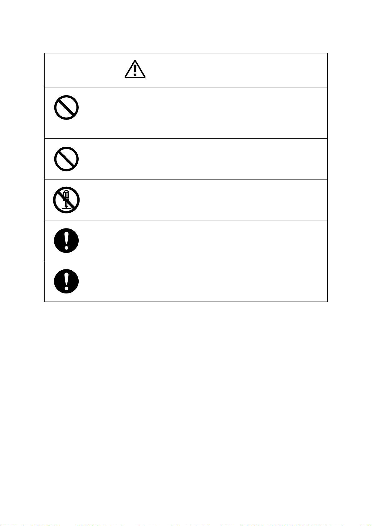
Examples of Pictorial Indication
The mark represents CAUTION (including DANGER and
WARNING).
Electric Shock
Disassembling
Prohibited
Disconnect
the power plug
Detailed contents of CAUTION ("Electric Shock" in the example
on the left) is shown in the mark.
The mark represents prohibition.
Detailed contents of the prohibited action ("Disassembling
Prohibited" in the example on the left) is shown in the mark.
The mark represents instruction.
Detailed contents of the instruction ("Disconnect the power plug"
in the example on the left) is shown in the mark.
Warning Label
There is a warning label on the top cover of the equipment.
Do not try to remove, break or modify the label.
xi
Page 14
Precautions upon Equipment Operation
DANGER
Never attempt to check or repair the inside of the equipment.
Checking or repair by an unqualified person may cause a fire or an electric
shock.
Contact our head office, or a nearby branch or local office to request
servicing.
Never remove the cover of this equipment.
Touching the high-voltage section inside will cause an electric shock.
Do not attempt to disassemble or tamper with this equipment.
Otherwise, a fire, an electric shock, or a malfunction may occur.
When conducting maintenance, make sure to turn the main power off.
Failure may result in electric shock.
Turn off all the main powers before cleaning the equipment. Make sure to turn
it off since voltage is still outputted from the rectifier even after the indicator
and the radar are turned off. Failure may result in equipment failure, or death
or serious injury due to electric shock.
xii
Page 15

cause a breakdown.
When turning off the power supply, do not hold down the power button of the
operation unit.
Otherwise, a trouble may occur due to termination failure.
When conducting maintenance work, make sure to turn off the power so that
the power supply to the equipment is completely cut off.
Some equipment components can carry electrical current even after the
power switch is turned off, and conducting maintenance work may result in
electric shock, equipment failure, or accidents.
When cleaning the display screen, do not wipe it too strongly with a dry cloth.
Also, do not use gasoline or thinner to clean the screen. Failure will result in
damage to the screen surface.
Confirm computer virus does not exist in USB flash memory beforehand
when reading and writing of the file by using USB flash memory.
Influences other equipment when the display unit is infected with the virus,
and it may cause a breakdown.
Do not remove USB flash memory while the access lamp (in USB flash drive)
is flashing.
Data may be damaged when the USB flash memory is inserted or removed
while accessing it, and it may cause a breakdown.
Confirm computer virus does not exist in external storage media beforehand when
reading and writing of the file by using external storage media.
Influences other equipment when the display unit is infected with the virus, and it may
In case water or a metal object gets inside the equipment, turn off the power
immediately, unplug the power supply cable from an electric outlet, and
contact our head office, or a nearby branch or local office to request servicing.
Keeping the equipment in operation under such condition may cause a fire,
an electric shock or a malfunction.
In case you find smoke, unusual odor or extreme high heat coming from the
equipment, turn off the power immediately, unplug the power supply cable
from an electric outlet, and contact our head office, or a nearby branch or
local office to request servicing.
Keeping the equipment in operation under such condition may cause a fire or
an electric shock.
xiii
Page 16

of the Day/Night button, particularly the use of the
other tracking targets will not be displayed correctly and may cause an
on the collision judgement of AIS targets.
Do not use the offset function during navigation.
If the equipment is used with the offset value entered as the own ship position
(deviated from the actual position), accidents may result.
Change of the colour
[Night] colour, may interfere with the recognition of display information.
Confirm display information can be recognised.
Do not turn off the power during Backup/Restore.
Otherwise, a function may fail, and an accident may occur.
Do not turn off the power supply during recovery of C drive image.
Otherwise, a function fault occurs, causing an accident.
The reference target function is to be used if the own ship's speed cannot be
displayed normally due to trouble such as a speed sensor malfunction. Do not
use the reference target function except in emergencies.
Do not set as a reference target a large radar echo such as a land target. The
vectors of the speed and other tracking targets will not be displayed correctly
and may cause an accident.
Do not set as a reference target a sailing ship. The vectors of the speed and
accident.
Do not use own speed based on reference target tracking for relative speed
and CPA/TCPA calculation of AIS targets because the response of own speed
is slower than actual own ship's speed change and it may cause a big error
xiv
Page 17

Do not use or leave the equipment under direct sunlight for a long time or in
the temperatures above 55°C.
Otherwise, a fire or a malfunction may occur.
Do not place a glass or cup containing water, etc., or a small metal object on
this equipment.
If water or such object gets inside, a fire, an electric shock, or a malfunction
may occur.
Do not touch the equipment with hands or gloves wet with water.
Otherwise, an electric shock or a malfunction may occur.
• Do not place any object on the operation panel.
In particular, if a hot object is placed on the operation panel, it can cause
deformation of the surface of the operation panel.
• Do not apply any undue shock on the operation panel, trackball and dials.
Otherwise, a malfunction may result.
Make sure that the main power is turned off before inspection or replacement
of parts.
Otherwise, an electric shock, a fire, or a malfunction may occur.
Information is displayed in addition to a warning or a caution in the alert status
area.
Information is used to report operation errors and so on to the users.
Unlike other alerts, no detail display is provided for Information.
xv
Page 18

Glossary
AIO : Admiralty Information Overlay published by United Kingdom
Hydrographic Office (UKHO).
AIS : Automatic Identification System
AZ : Acquisition/Activation zone
Anti-clutter rain : Rain/snow clutter suppression
Anti-clutter sea : Sea clutter suppression
AZI : AZImuth stabilisation mode
BCR/BCT : Bow Crossing Range/Bow Crossing Time
Chart Maintenance : Software to manage the charts. Imports and updates the charts.
C-MAP MAX*
CTS : Course To Steer. Heading command.
COG : Course Over the Ground
C UP : Course up. Own ship’s course is pointed to the top centre of the radar
CCRP : Consistent Common Reference Point. The own ship position, to which
CORREL : CORRELation
CPA/TCPA : Distance to the Closest Point of Approach/Time to the Closest Point of
CTW : Course Through Water. The direction of the ship's movement through
DIST : Distance
DNV : Det Norske Veritas
DRIFT : The current velocity for manual correction or the current speed on the
EBL : Electronic Bearing Line
ETA : Estimated Time of Arrival
ENH : Enhance
GPS : Global Positioning System
HDG : Heading. Ship’s heading
HL : Heading Line
HSC : High Speed Craft. Vessels which comply with the definition in SOLAS
H UP : Head up. Own ship’s heading line is always pointed to the top centre
IHO : International Hydrographic Office
IMO : International Maritime Organisation
IR : Radar Interference Rejecter
ISW : InterSWitch unit
LMT : Local Mean Time
LON : Longitude
LAT : Latitude
1
: Digital chart data by C-MAP
display.
all horizontal measurements such as target range, bearing, relative
course, relative speed, CPA or TCPA are referenced, typically the
conning position of the bridge.
Approach.
the water
horizontal axis of the 2-axis log is displayed.
for high speed craft
of the radar display.
xvi
Page 19

LP : Long Pulse
MED : Marine Equipment Directive. Request standard for standardisation of
marine equipment within the EU region
MFD : The formal name is Multi Function Display. The navigation support
functions such as RADAR, ECDIS, CID, and AMS can be executed by
switching.
MMSI : Maritime Mobile Service Identity
MOB : Man Over Board
MON : Performance MONitor
MP : Medium Pulse
newpec : Electronic navigational chart by Japan Hydrographic Association
NM : Nautical Mile 1 nm=1852 m
N UP : The north is always pointed to the top centre of the radar display.
(North up)
P0N : Unmodulated pulse, which is a type of transmission radio wave. While
it is a type of radio wave usually used by radars equipped with
magnetrons, radio waves with a short pulse length are used also by
solid-state radars for short-range detection.
PI : Parallel Index line
Past positions : Equally time-spaced past position marks of a tracked or AIS target and
the own ship.
POSN : POSitioN
PRF : Pulse Repetition Frequency. The number of radar pulses transmitted
each second.
PROC : PROCess. Radar signal processing function
Q0N : A type of radio wave with intra-pulse frequency modulation. It is used
for solid-state pulse compression radars.
RL : Rhumb Line
RR : Range Rings
Relative vector : A predicted movement of a target relative to own ship’s motion
RM : Relative Motion. A display on which the position of own ship remains
fixed, and all targets move relative to own ship.
RM(R) : Relative Motion. Relative Trails
RM(T) : Relative Motion. True Trails
ROT : Rate Of Turn. Change of heading per time unit
Route : A set of waypoints
RPU : RADAR Processing Unit
SOG : Speed Over the Ground
SART : Search And Rescue Transponder
SET : The current direction for manual correction or the current speed on the
horizontal axis of the 2-axis log is displayed.
SLC : Serial LAN Interface Circuit
SP : Short Pulse
STAB : STABilisation
STW : Speed Through Water
TCPA : Time to Closest Point of Approach to own ship
xvii
Page 20

TM : True Motion. A display across which the own ship and targets move
with their own true motions.
To W PT : To Waypoint (To WPT)
Trails : Tracks displayed by the radar echoes of targets in the form of an
afterglow
Trial manoeuvre : A graphical simulation facility used to assist the operator to perform a
proposed manoeuvre for navigation and collision avoidance purposes
True vector : A vector representing the predicted true motion of a target, as a result
of input of the course and speed of the own ship
TT : Target Tracking
TTG : Time To Go. Time to next waypoint.
TXRX : Transmitter-Receiver Unit
UTC : Universal Time, Coordinated
VRM : Variable Range Marker
VDR : Voyage Data Recorder
WOL : Wheel Over Line
WPT : Waypoint
XTD : Cross Track Distance
XTL : Cross Track Limit
Activated target : A target representing the automatic or manual activation of a sleeping
AIS target for the display of additional information
Associated target : A target simultaneously representing a tracked target and a AIS target
which are decided as the same
Chirp : A type of transmission waveform with intra-pulse frequency
modulation used by solid-state radars. Its radio wave type is classified
as Q0N.
Clutter : Unwanted reflections on a radar screen, from sea surface, rain or
snow.
Display : Screen displayed on the LCD
Frequency deviation range : The range of variation of the Q0N frequency used for transmission
waves of a solid-state radar. Generally, the greater the frequency
deviation range, the higher the resolution in the range direction.
Interswitch Unit : A device to switch over two or more radar display units and two or
more radar antennas
Leg : Line between two consecutive waypoints
Lost AIS target : A target symbol representing the last valid position of an AIS target
before the reception of its data was lost, or its last dead-reckoned
position.
Lost tracked target : One for which target information is no longer available due to poor, lost
or obscured signals.
Power amplifier : A radio frequency amplifier circuit consisting of semiconductor
elements used for solid-state radars. It employs a high frequency, high
power FET.
Primary : Main positioning sensor
xviii
Page 21

Pulse compression : Correlation processing performed when a transmitted chirp signal is
received by a solid-state radar after reflecting off the target. This
processing gain enables the radar to have necessary detection
capability even when a transmission power is low.
Radar beacon : A navigation aid which responds to the radar transmission and
generates radio wave
Range : An area of the chart displayed on the screen. Represented by one half
of the length of the chart display screen.
Range side lobe : False image that is generated as a result of pulse compression
processing in the solid-state radar when there is a large target such as
a large ship in the vicinity.
Reference target : A fixed target specified to calculate the speed over the ground
Rubber band : Border that indicates the selected range.
Scale : The display scale
Sea state : The average height of the wave expressed by dividing into several
classes.
Sleeping AIS target : A target indicating the presence and orientation of a vessel equipped
with AIS
Spot depth : Numeric representation of depth
SSR: Solid State Radar : Radar that uses semiconductor elements instead of magnetron, which
requires periodic replacement. It is built with a system that ensures
necessary detection capability even when a transmission output is low,
by using chirp signals with a long pulse length upon transmission and
performing pulse compression upon reception
*1 © C-MAP 2017, All rights reserved.
xix
Page 22

Notations
Type
Notation
Operation of menu
[Menu] button → User Map → File Operation
Position of menu
[User Map] – [File Operation]
Operation notations
Trackball operations on the operation panel are expressed as follows.
Operation Notation
Click the left button. Click
Example: Click on the object.
Double-click the left button. Double-click
Example: Determine the drawing by double-click.
Click the right button Click the right mouse button
Example: Display the context menu by clicking the right mouse
button.
Button notations
The buttons and dialogue boxes on the screen are expressed as follows.
Button type
Notation
Button with button name indicated
Button with an indication other than the
button name such as an icon
Menu notations
A series menus are expressed as follows.
Example:
Shown as follows.
Example: → Day/Night button
→ [AUTO] (automatic) button
xx
Page 23

Contents
PREFACE ................................................................................................................... i
Pictorial Indication .................................................................................................. xi
Precautions upon Equipment Operation ............................................................. xii
Section 1 Overview ............................................................................................. 1-1
1.1 Functions ............................................................................................................................... 1-2
1.2 Features ................................................................................................................................ 1-3
Section 2 Basic Operations and Mode Screen ................................................. 2-1
2.1 Changing the Mode ............................................................................................................... 2-1
2.2 Sections and Features of the Mode Screen.......................................................................... 2-2
2.2.1 Menu button .................................................................................................................. 2-2
2.2.2 Key assignment display area ........................................................................................ 2-3
2.2.3 Ship information ............................................................................................................ 2-4
2.2.4 Right tool bar ................................................................................................................. 2-7
2.2.5 Tool bar ......................................................................................................................... 2-8
2.2.6 Alert notification area .................................................................................................. 2-10
2.2.7 Chart information area ................................................................................................ 2-11
2.2.8 Sub information area .................................................................................................. 2-18
2.3 Common Information Window ............................................................................................. 2-23
2.4 Operating the Information Monitoring Window ................................................................... 2-24
2.4.1 Opening the information monitoring window .............................................................. 2-24
2.4.2 Opening the information monitoring window from a dialogue other than the [Page
Selection] dialogue...................................................................................................... 2-27
2.5 Managing Files on the [File Manager] Dialogue ................................................................. 2-28
2.5.1 Managing the files ....................................................................................................... 2-28
2.5.2 Loading/saving the destination route file .................................................................... 2-30
Section 3 Operations on the Chart Screen ....................................................... 3-1
3.1 Displaying the Chart in Multi-View Display ........................................................................... 3-1
3.1.1 Displaying the multi-view screen .................................................................................. 3-1
3.1.2 Operating the multi-view screen ................................................................................... 3-2
3.2 Operating EBL/VRM via the Context Menu .......................................................................... 3-3
3.2.1 Operation via [Dropped EBL/VRM] - [Make EBL1/VRM1] or [Make EBL2/VRM2]
...................................................................................................................................... 3-4
3.2.2 Operation via [Dropped EBL/VRM] - [Make EBL1] or [Make EBL2] .......................... 3-4
3.2.3 Operation via [Dropped EBL/VRM] - [Make VRM1] or [Make VRM2] ........................ 3-5
(1) Contents
Page 24

3.2.4 Operation via [Dropped EBL/VRM] - [Move base point of EBL1/VRM1] or
[Move base point of EBL2/VRM2]................................................................................. 3-5
3.2.5 Operation via [CCRP EBL/VRM] - [Make EBL1/VRM1] or [Make EBL2/ VRM2] ....... 3-5
3.2.6 Operation via [CCRP EBL/VRM] - [Make EBL1] or [Make EBL2] .............................. 3-6
3.2.7 Operation via [CCRP EBL/VRM] - [Make VRM1] or [Make VRM2] ........................... 3-6
3.3 Displaying the EBL/VRM Button ........................................................................................... 3-7
3.4 Displaying the [CURS INFO] Dialogue ................................................................................. 3-8
3.4.1 Setting the base point for CURS INFO ......................................................................... 3-9
Section 4 Route Planning ................................................................................... 4-1
4.1 Overview of the Destination Route ....................................................................................... 4-1
4.1.1 Flow of destination route creation ................................................................................. 4-1
4.1.2 Editing the destination route ......................................................................................... 4-2
4.2 Route Display Settings .......................................................................................................... 4-3
4.2.1 Configuring [View] - [WPT/Route] from the menu ........................................................ 4-3
4.3 Opening the [Route/Destination] Dialogue............................................................................ 4-4
4.3.1 Key assignment on the operating unit .......................................................................... 4-5
4.4 Creating a New Destination Route ........................................................................................ 4-6
4.4.1 Registering a new proposed destination ...................................................................... 4-6
4.4.2 Creating a new destination route .................................................................................. 4-7
4.5 Editing Proposed Destinations ............................................................................................ 4-11
4.5.1 Edit on the [Destination List] dialogue ........................................................................ 4-11
4.6 Editing the Destination Route ............................................................................................. 4-14
4.6.1 Edit on the [Route/Destination] dialogue .................................................................... 4-14
4.6.2 Edit on the [Route List] dialogue ................................................................................. 4-15
4.7 Creating a Temporal Route ................................................................................................. 4-16
4.8 Creating a GoTo Route (Temporal Route Between Two Points) ......................................... 4-17
Section 5 Route monitoring ............................................................................... 5-1
5.1 About Route Monitoring ........................................................................................................ 5-1
5.1.1 Starting the route monitoring ......................................................................................... 5-1
5.1.2 Ending the route monitoring .......................................................................................... 5-3
5.2 Route Monitoring Settings ..................................................................................................... 5-4
5.2.1 Configuring [View] - [WPT/ROUTE] from the menu ..................................................... 5-4
5.2.2 Configuring [Settings] - [Route] from the menu ............................................................ 5-5
5.3 [Voyage Information] Dialogue .............................................................................................. 5-6
5.4 Reversing the Route ............................................................................................................. 5-8
5.5 Changing the To WPT ........................................................................................................... 5-9
5.5.1 Changing to WPT using the [Route Monitoring] dialogue ............................................. 5-9
5.5.2 Changing to WPT using the [Route/Destination] dialogue ......................................... 5-9
Section 6 Settings ............................................................................................... 6-1
6.1 Chart Settings ....................................................................................................................... 6-1
Contents (2)
Page 25

6.1.1 Registering/displaying my Ports ................................................................................... 6-1
6.1.2 Displaying the chart by inputting the position ............................................................... 6-2
6.2 Screen Display Settings ........................................................................................................ 6-3
6.2.1 Configuring the ship symbol display ............................................................................. 6-3
6.2.2 Configuring the own track display ................................................................................. 6-4
6.2.3 Configuring the TT/AIS target display ........................................................................... 6-8
6.2.4 Configuring the distance/direction measuring function display..................................... 6-9
6.2.5 Configuring display of the sub information area ......................................................... 6-10
6.3 Alert Settings ....................................................................................................................... 6-11
6.3.1 Configuring the alerts for the destination route ........................................................... 6-11
6.4 Operating Mode Settings .................................................................................................... 6-12
6.4.1 Configuring the basic settings of radar signal processing .......................................... 6-12
6.4.2 Configuring the scale and range ................................................................................. 6-13
6.4.3 Configuring the chart operation .................................................................................. 6-16
6.4.4 Configuring the current position display...................................................................... 6-17
6.4.5 Setting the colour and brightness ............................................................................... 6-19
6.4.6 Setting the key assignment ......................................................................................... 6-20
6.4.7 Configuring user preferences ..................................................................................... 6-22
Section 7 Specifications ..................................................................................... 7-1
7.1 Plotter Functions ................................................................................................................... 7-1
Appendix A Alert List ........................................................................................ A-1
A.1 Alarms ................................................................................................................................... A-2
A.2 Warnings ............................................................................................................................... A-3
A.3 Cautions ................................................................................................................................ A-9
A.4 List of Alert Icons ................................................................................................................. A-10
Appendix B
B.1 Menu List .................................................................................................................................... B-1
B.1.1 Route Planning (Destination Route) ............................................................................. B-1
B.1.2 Route Monitoring (Destination Route) .......................................................................... B-2
B.1.3 Route Monitoring (NMEA) ............................................................................................. B-2
B.1.4 Anchor Watch .................................................................................................................... B-3
B.1.5 Chart ............................................................................................................................. B-3
B.1.6 User Map ...................................................................................................................... B-4
B.1.7 TT/AIS ........................................................................................................................... B-5
B.1.8 Tools .............................................................................................................................. B-9
B.1.9 View ............................................................................................................................ B-12
B.1.10 Alert ............................................................................................................................... B-19
B.1.11 Settings ......................................................................................................................... B-20
B.1.12 Maintenance ............................................................................................................... B-30
B.1.13 Help ............................................................................................................................. B-32
Menu List and Materials
................................................................... B-1
(3) Contents
Page 26

B.1.14 Code Input .................................................................................................................... B-32
B.1.15 Service ........................................................................................................................ B-33
B.2 Context Menu List .................................................................................................................... B-38
B.2.1 No object (RADAR/Synthesis mode) .............................................................................. B-38
B.2.2 No object (Plotter mode) ................................................................................................. B-38
B.2.3 AIS................................................................................................................................... B-39
B.2.4 TT .................................................................................................................................... B-45
B.2.5 GPS Buoy ....................................................................................................................... B-46
B.2.6 NAVTEX .......................................................................................................................... B-46
B.2.7 User Map ........................................................................................................................ B-47
B.2.8 Monitoring dargging anchor ............................................................................................ B-49
B.3 List of Terminologies, Units, and Abbreviations ........................................................................ B-50
B.4 List of Navigation - related Symbols......................................................................................... B-58
B.4.1 Navigation monitoring related ......................................................................................... B-58
B.5 List of Icons/Icon Buttons ......................................................................................................... B-59
B.6 Cursor types ............................................................................................................................. B-64
Software Licence Agreement .......................................................................................................... B-66
Font Licence Agreement ................................................................................................................. B-67
IPA Font Licence Agreement v1.0 .................................................................................................. B-68
Contents (4)
Page 27

2
Section 2 Basic Operations and
See also the Instruction Manual of the ship radar equipment.
See 2.2.3 Ship information.
See 2.2.7 Chart information area.
See 2.2.1 Menu button.
See 2.2.2 Key assignment display area.
See 2.2.4 Right tool bar.
See 2.2.8 Sub information
See 2.2.5 Tool bar.
See 3.4 Displaying the
See 2.4 Operating the
Mode Screen
2.1 Changing the Mode
If an optional plotter is installed on the JMR-5400 series ship radar equipment, use the mode switching
button on the right tool bar to switch the mode between the radar mode, synthesis mode, and plotter
mode.
Memo
For details of the right tool bar, see 2.2.4 Right tool bar.
Mode screen in plotter mode
The following shows an example of the mode screen in plotter mode and relevant sections to be
referenced for each part of the screen.
area.
Information Monitoring
Window.
Memo
This document describes operations in plotter mode.
2-1 Section 2 Basic Operations and Mode Screen
Cursor Information
Dialogue.
See 2.2.6 Alert notification area.
Page 28

Menu item
Reference
Route/Destination
4.6.1 Edit on the [Route/Destination] dialogue
Route Planning → Destination List
4.5.1 Edit on the [Destination List] dialogue
4.6.2 Edit on the [Route List] dialogue
5.1.2 Ending the route monitoring
Chart → My Port List
6.1.1 Registering/displaying my Ports
Position
Tools → EBL/VRM
3.3 Displaying the EBL/VRM Button
Tools → Cursor Readout
3.4 Displaying the [Cursor Readout] Dialogue
Tools → File Manager
2.5 Managing Files on the [File Manager] Dialogue
View → Own Ship
6.2.1 Configuring the ship symbol display
View → Own Track
6.2.2 Configuring own track display
5.2.1 Configuring [View] - [WPT/Route] from the menu
View → Target
6.2.3 Configuring the TT/AIS target display
View → Chart View
3.1 Displaying the Chart in Multi-view Display
display
View → Control
6.2.5 Configuring display of the sub information area
Alert → Route
6.3.1 Configuring the alerts for the destination route
Settings → Signal Process(Basic)
6.4.1 Configuring the basic settings of radar signal processing
Settings → Route
5.2.2 Configuring [Settings] - [Route] from the menu
Settings → Preferences
6.4.4 Configuring the user preferences
Settings → Scale/Range Preset
6.4.3 Configuring the scale and range
Settings → Position Display
6.4.2 Configuring the current position display
2.2 Sections and Features of the Mode
Screen
2.2.1 Menu button
Click on the menu button to display the top menu.
For details of menu operations, see the Instruction Manual of the ship radar equipment.
Menu in plotter mode
The following table lists the menu items displayed only in plotter mode, menu items to which items only
enabled in plotter mode are added, and menu items whose contents differ in plotter mode. The table
also provide sections related to these menu items.
Route Planning → Set
Route Planning → Route List
Route Monitoring
Chart → Off Centre by Entering
View → WPT/Route
4.3 Opening the [Route/Destination] Dialogue
4.4.2.2 Creating a route on the [Route List] dialogue
5.1.1 Starting the route monitoring
6.1.2 Displaying the chart by inputting the position
4.2.1 Configuring [View] - [WPT/Route] from the menu
View → Tools
Section 2 Basic Operations and Mode Screen 2-2
6.2.4 Configuring the distance/direction measuring function
Page 29

2
No.
Function name
Functional overview
1
Vector Time
Select a vector length.
2
C UP Angle
Change the course up angle.
3
Own Track Colour
Select an own track colour.
4
Mark/Line Colour
User map colour
5
Manual Tune
Adjustment of manual tuning
6
Display Brightness
Adjust the brightness of the display unit.
7
Panel Brightness
Adjust the brightness of the operating unit.
8
Gain
Adjust the sensitivity.
9
Sea
Remove sea clutter.
10
Rain
Remove rain and snow clutter.
Assigned function
2.2.2 Key assignment display area
Rotate the [Multi] Dial to operate assigned functions.
2.2.2.1 Change the assignment
1
Press the [Multi] Dial.
The Key Assignment dialogue box is displayed.
2 Rotate the [Multi] Dial to select an assigned function from [Multi Dial].
In plotter mode, the following functions can be selected.
2-3 Section 2 Basic Operations and Mode Screen
Page 30

precision will be less than ±1° at velocities of more than 17 kn.
2.2.3 Ship information
Do not use the offset function while the ship is underway.
If the equipment is used with an offset value input in the ship position (state of being
shifted from the actual position), an accident may be caused.
The ship information is displayed.
Memo
• When the 1-axis log is used, the velocity component in the forward direction can be detected
but the velocity component in the lateral direction cannot be detected. Therefore, the leeway
effect (off-course movement due to wind) cannot be detected.
• When the 2-axis ground log is used, the accuracy may degrade in a shoal. The velocity may not
be detected in the abyssal zone.
• When the GPS is used, the COG precision will be less than ±3° at velocities of 1 to 17 kn. The
Section 2 Basic Operations and Mode Screen 2-4
Page 31

2
Sensor name
Description
HDG
Displays the value of the heading direction sensor.
STW
Displays the value of the water speed sensor.
COG/SOG
Displays the value of the ground speed sensor.
Sensor name
Sensor source
HDG
Manual, Gyro, Gyro 1
, Gyro 2
, MAG (MAG Compass)*4, G/C (GPS Compass)
STW
Manual, Log*5, Log 1
, Log 2
COG
SOG
See the next page.
Sensor information
Sensor information is displayed.
Sensor type
UTC/Local date and time
The current date and time are displayed.
Click on it to switch between the UTC time and the local
time.
From the menu, select [Maintenance] - [Date/Time/Time
Zone] - [Display Style] to configure the date format.
For details of configuring the data and time, see the
Instruction Manual of the ship radar equipment.
Background colours for sensor values
The meanings of the background colours are as follows.
Normal: Indicates a normal sensor value.
Yellow: The reliability of the sensor value is low.
Yellowish orange: The sensor value is abnormal.
Switching the sensor source
Select a sensor source from the [Source] combo box. The following sensor sources can be selected.
Select [Menu...] to display the [Sensor Selection/Status] dialogue.
*1*4
*2*5
*1*4
*2*5
*5
Log
, Log 1
*1: Only with two gyrocompasses
*2: Only with two logs
*3: "x" indicates a device number if more than one GPS is used.
*4: If a gyrocompass system with the automatic switching feature is used, the sensor source display is
automatically changed depending on the switching status.
*5: Logs with 1AX installed cannot be selected from the sensor source.
*2*5
, Log 2
2-5 Section 2 Basic Operations and Mode Screen
*2*5
, GPSx*3
Page 32

Data name
Sensor source
Position
GPSx*, manual
(1)
(2)
(3)
(5)
(4)
(6)
See the previous page.
[Position] dialogue
The position information is displayed.
(1) The position data name is displayed.
(2) The position sensor source is displayed.
Select a sensor source from the [Source] combo box. The following sensor sources can be
selected.
Select [Menu...] to display the [Sensor Selection/Status] dialogue.
* "x" indicates a device number if more than one GPS is used.
(3) The Geodetic Positioning System of POSN is displayed.
(4) The positioning precision is displayed.
If the positioning precision is differential positioning, "DGPS" is displayed. If the positioning is
GPS-alone positioning, nothing is displayed.
(5) CCRP position
The CCRP position from the primary sensor is displayed.
(6) Badge display area
Offset : This badge is displayed, when offset is set for own ship’s position.
AFT :
EBL/VRM :
V :
This badge is displayed, when AFT Operation is enabled.
This badge is displayed, when EBL/VRM cursor mode is enabled.
This badge is displayed, when GPS Buoy mode is enabled.
Section 2 Basic Operations and Mode Screen 2-6
Page 33

2
Mode
Icon
Daytime/night button
MOB (Man Over Board) button
Message notification button
The badge on the icon indicates the no. of unread messages.
Brightness adjustment button for the
2.2.4 Right tool bar
The following describes the functions of buttons on the right tool bar.
Change the screen brightness in five steps
depending on the brightness in the bridge.
For details, see the Instruction Manual of
the ship radar equipment.
screen and operating unit
The screen brightness can be adjusted in the
range of 0 to 100, and the brightness of the
operating unit can be adjusted in the range of
0 to 4 (five steps).
For details, see the Instruction Manual of the
ship radar equipment.
Click on it to display the latest notification messages received
regarding AIS, MSG Tray, and NAVTEX.
For details of the message dialogue of each received
information, see the Instruction Manual of the ship radar
equipment.
In case someone falls over board, the ship position
when this button is clicked on is marked so as not
lose the fallover position.
For details, see the Instruction Manual of the ship
radar equipment.
Mode change button
Click on it to change the mode.
The mode can be switched between [Radar mode], [Synthesis mode], and
[Plotter mode] in this order.
The icon also changes accordingly when the mode changes.
Radar mode
Synthesis mode
Plotter mode
2-7 Section 2 Basic Operations and Mode Screen
Page 34

Click on the disclosure button
Disclosure
2.2.5 Tool bar
The following describes the functions of buttons on the tool bar.
Some buttons are hidden in normal cases.
Change the button display by clicking on the disclosure button.
Displayed in normal cases Hidden in normal cases
button
to show the buttons that are
hidden in normal cases.
See the next page for the name and description of each button.
Section 2 Basic Operations and Mode Screen 2-8
Page 35

2
[U.Map] (user map) button
[AUTO] (Cursor mode selection)
[Undo] (cancel) button
[Data Off] button
2.2.5.1 Buttons displayed in normal cases
button
Click on it to set the cursor mode to the
AUTO mode.
For details of the cursor mode, see the
Instruction Manual of the ship radar
equipment.
Click on it to display only the main
information and hide other information.
The following information will be displayed.
RADAR
- Echo/trail
- Cursor
Plotter
- Chart
- Own ship symbol
- Route
- Cursor
Click on it to display the tool bar for
drawing the user map.
Cancels the previous operation.
Operations in the following mode can be
cancelled.
• User map creation mode
• Own Track
• Target Track
2-9 Section 2 Basic Operations and Mode Screen
Page 36

[Map On/Off] button
[Screen capture] button
[HL Off] button
Eraser tool button
[Def.] button
[Favourite] button
2.2.5.2 Buttons hidden in normal cases
Resets the user preferences to the factory
default settings.
It works in the same way as the [Initialise
the displayed settings] button on the [User
preferences] dialogue of the [Settings]
menu.
For details, see the Instruction Manual of
the ship radar equipment.
Click on it to capture the current screen.
For details, see the Instruction Manual of
the ship radar equipment.
Click on it to activate the user map deletion
mode. Continuous deletion is possible.
Shows or hides the user map.
Click on it to hide the heading flash.
For details of the heading flash, see the
Instruction Manual of the ship radar
equipment.
Click on it to display the list of functions
registered in the favourite.
For details, see the Instruction Manual of
the ship radar equipment.
2.2.6 Alert notification area
When an alert is issued, the alert status, content, and the number of occurrences are displayed in the
alert notification area.
For details of the alert confirmation and approval operations, see the Instruction Manual of the ship
radar equipment.
Section 2 Basic Operations and Mode Screen 2-10
Page 37

2
Scale value
Range value
2.2.7 Chart information area
The chart information area consists of the following information display sections, buttons and tools.
2.2.7.1 Scale/range combo box
The current scale or range is displayed.
.
Scale Range
Select a scale or range from this combo box.
Click on the scale/range combo box to display the scale/range selection list.
Select a scale or range value from the list to display the chart with the selected scale or range.
2-11 Section 2 Basic Operations and Mode Screen
Page 38

Setting item
Description
that the ship is always displayed in the upper part of the screen.
relatively.
disappears when it moves.
2.2.7.2 Motion mode combo box
Displays the current motion mode.
Select a motion mode from the combo box.
Click on the motion mode combo box to select a motion mode.
True Motion Mode
[TM]
[RM]
The ground and other objects are fixed on the screen and only the ship moves. The
chart automatically shifts when the ship reaches the predefined end of the screen so
Relative Motion Mode
The ship is fixed in the centre of the screen, and the ground and other objects move
Free mode
[Free]
The chart can be moved freely regardless of the ship's traveling direction. The ship
Section 2 Basic Operations and Mode Screen 2-12
Page 39

2
Setting item
Description
object can be read easily.
selected in TM (true motion) or Fee mode.
• The ship's heading direction (HDG) is fixed on top in course up mode.
Click on [] to complete the input.
monitoring.
2.2.7.3 Direction mode combo box
Displays the current direction mode.
Select a direction mode from the combo box.
Click on the direction mode combo box to select a direction mode.
North Up (true bearing)
[N UP]
[H UP]
• The chart is displayed with the north always on top. It provides great chart
visibility because of no flickering of fixed objects, and the true bearing of each
Head Up (relative bearing)
• The chart is displayed with the ship's heading direction upward. It cannot be
[C UP]
[C UP (Angle
Setting)...]
[D UP]
Course Up display
Course Up display (course angle setting)
• Select this to display the [C UP (Angle Setting)] dialogue. The course angle
(heading angle) set on the dialogue is fixed on top of the screen.
- Enter the angle in the [Angle] field on the [C UP (Angle Setting)] dialogue.
- Move the angle input slider to adjust the value.
-
Destination Up
• To WPT (destination) is always displayed in the upper section of the screen. It
can be selected only if the motion mode is RM (relative motion) and during route
2-13 Section 2 Basic Operations and Mode Screen
Page 40

Button
Description
Icon
Status
2.2.7.4 [HOME] button
Click on it to move the chart so that the ship position is displayed.
This button is useful when you lose sight of the ship position.
2.2.7.5 [Mark] (mark input position)
Select a position to insert a mark when inserting a mark using a numeric key.
Click on the mark positioning button to change the button as follows.
Insert a mark on the ship position.
Insert a mark on the cursor position.
2.2.7.6 [SD Card Removal] button
Displayed when a C-MAP MAX SD card is inserted.
To remove the SD card, click on this button, and remove the card after the icon is set to a removal
enabled status.
The statuses of the icon are shown in the table below.
Enabled. When this icon is clicked on the removal of the card is
requested.
Disabled. The removal of the card is disabled while card removal is
being requested.
Removal enabled. The card removal request is successful and the SD
card can be removed.
2.2.7.7 [Mark] (user map colour)
Displays the user map colour common to marks, lines, and texts.
When the [Mark] is enclosed with blue borders, the
Click on the colour icon to display the [Plot Colour] dialogue on which you can select a colour from the
following.
White/Grey/Amber/Magenta/Blue/Cyan/Green/Yellow/Orange/Dark Red
Section 2 Basic Operations and Mode Screen 2-14
[MULTI] dial is assigned the colour change function.
Page 41

2
2.2.7.8 [Track] (own track colour)
The current ship's own track colour is displayed.
When the [Track] is enclosed with blue borders, the multi-function knob is assigned the colour change
function.
Click on the colour icon to display the [Plot Colour] dialogue on which you can select a colour from the
following.
White/Grey/Amber/Magenta/Blue/Cyan/Green/Yellow/Orange/Dark Red
2-15 Section 2 Basic Operations and Mode Screen
Page 42

Observation scene
Definition
Standard
Standard
so many ships are present. (The resolution is prioritized.)
sensitivity is prioritized.)
degrades.)
degrades a little.)
Calm
Used when the rain and snow clutter or sea clutter is not significant.
degrades a little.)
Bird
Used to detect seabirds.
Long
Used for monitoring in a relatively long distance in the ocean.
(Objects with low detection ratios are displayed.)
User1
General-purpose mode used when all the above nine types are not relevant.
User2
General-purpose mode used when all the above nine types are not relevant.
selected range*1.
2.2.7.9 Observation scene selection button
Displays the current observation scene.
The signal processing pattern is set in accordance with the normal use state in order to acquire optimal
radar images. Select an observation scene in accordance with the current oceanographic condition to
acquire optimal images.
Click on the observation scene selection button and select an observation scene in accordance with
the current oceanographic condition from the [Selection] (observation scene selection) dialogue.
Coast
Open-sea
Fishnet
Storm
Rain
Buoy
Used for monitoring in a short distance such as a zone inside the bay where
Used for monitoring in a long distance such as the ocean. (The long distance
Used to detect floating fishnet and other small objects hidden in see clutter.
(Sea clutter restriction is prioritized while the sensitivity of moving objects
Used in storms where the rain and snow clutter or sea clutter is significant.
(Sea/rain and snow clutter restriction is prioritized while the sensitivity
Used when the sea clutter is not significant but the rain and snow clutter is
significant. (Rain and snow clutter restriction is prioritized while the sensitivity
Used to detect small objects such as radio buoys outside the sea clutter.
AUTO(L)
A preset observation scene is selected automatically depending on the
*1: For details of automatic switching, see the Instruction Manual of the ship radar equipment.
Section 2 Basic Operations and Mode Screen 2-16
Page 43

2
[In] button
[Out] button
Slider
Selected area
2.2.7.10 Zoom slider
Used to scale the chart.
Click on it to zoom in the chart.
Move the slider knob upward to zoom in the chart.
Move the slider knob downward to zoom out the chart.
Click on it to zoom out the chart.
2.2.7.11 [Zoom] (zoom area) button
Enlarge the selected area to full-screen size.
Click on it to change the cursor to the zoom cursor.
Use the trackball to move the cursor to the upper left corner "A" of the target range, then move the
cursor to the bottom right corner "B", and then click on the button.
The selected area is enlarged to full-screen size.
The zoom cursor changes back to the cross-hair cursor.
2-17 Section 2 Basic Operations and Mode Screen
Page 44

Tabs
(2)
(3)
(1)
(4)
2.2.8 Sub information area
Click on each tab to display relevant information.
Memo
Tabs displayed differ depending on the setting on the [Control] dialogue of the [View] menu.
2.2.8.1 [Watch] dialogue
Click on each tab to display relevant information.
• [Watch] dialogue
(See 2.2.8.1 [Watch] dialogue.)
• [Depth] dialogue
(See 2.2.8.2 [Depth] dialogue.)
• [Current] dialogue
(See 2.2.8.3 [Current] dialogue.)
• [Trails] dialogue
(See 2.2.8.4 [Trails] dialogue.)
(1) [Vector(T)] (vector length) field
Enter the vector length.
Input range: 1 to 120 min
(2) Radar overlay button
Turns on/off the radar overlay display.
Click on it to turn on/off the overlay.
If the radar is not installed, nothing is displayed.
ON: OFF:
If multiple radars are installed, select radar system to use from the combo box.
Section 2 Basic Operations and Mode Screen 2-18
Page 45

2
(a)
(b)
(a)
(b)
(3) AIS (AIS function) button and AIS filter display button
(a) AIS (AIS function) button
Turns on/off AIS.
Click on it to turn on/off the function.
If AIS is disabled, nothing is displayed.
ON: OFF:
(b) AIS filter display button
When AIS is ON, [Filter] is displayed.
When the AIS filter is ON, [Filter] is enclosed with blue borders.
(4) TT1/TT2 (TT1/TT2 function) button
(a) TT1 (TT1 function) button
Turns on/off TT1.
Click on it to turn on/off the function.
If TT1 is disabled, nothing is displayed.
ON:
(b) TT2 (TT2 function) button
Turns on/off TT2.
Click on it to turn on/off the function.
If TT2 is disabled, nothing is displayed.
ON:
OFF:
OFF:
2-19 Section 2 Basic Operations and Mode Screen
Page 46

Tex t
Motion mode
Stabilisation mode
REL
Relative motion display (RM)
—
GND
True motion display (TM)
Speed over ground
SEA
True motion display (TM)
Speed through the water
(1)
(2)
(3)
REL, GND, or SEA is added to the end of the display names of TT1 and TT2 buttons depending on
the radar motion mode or stabilisation mode (e.g. TT1-GND).
To use a TTM sentence for the TT symbol display, an OSD sentence must be received from the
RADAR.
2.2.8.2 [Depth] dialogue
The [Depth] dialogue box is displayed if a depth sounder is installed.
(1) [Source]
Displays the depth sounder used.
FWD: Front depth sounder
AFT: Rear depth sounder
(2) [Depth]
Displays the water depth.
(3) [Measured from]
Displays the reference position to measure the water depth.
Transducer
Surface
Keel
Section 2 Basic Operations and Mode Screen 2-20
Page 47

2
Display mode
Description
No motion trails for fixed objects such as the land is drawn.
Motion trails for fixed objects such as the land are also drawn.
Land
Land
Trail
Ship
Trail
Ship
(1)
(2)
2.2.8.3 [Current] dialogue
(1) [Set]
Displays the direction of the current.
(2) [Drift]
Displays the speed of the current.
2.2.8.4 [Trails] dialogue
Use the [Trails] dialogue to set the display of other ships' trails.
True motion or relative motion can be used for the trail display mode.
Draws the absolute trails of other ships irrelevant to the own ship.
True motion display
Relative motion
display
This mode is useful to determine the courses and speeds of other ships.
Draws the trails of other ships relative to the own ship.
This mode is useful to determine whether other ships are coming closer to the
own ship.
True motion trail Relative motion trail
2-21 Section 2 Basic Operations and Mode Screen
Page 48

(1)
(2) (3)
(1) True/relative trail switching button
Click on it to change the trail display to true motion or relative motion.
T: True motion display
R: Relative motion display
Available trail display modes differ depending on the configured motion modes.
The display mode will be fixed to the true motion mode if the motion mode is TM (true motion).
(2) Trail length switching combo box
Changes the trail length
The following trail lengths can be selected depending on the radar trail length set in the radar mode.
Short mode: Off, 15 sec, 30 sec, 1 min, 3 min, 6 min, 10 min, 15 min, 30 min, 60 min
Long mode: Off, 30 min, 1 hour, 2 to 24 hours (units of hours)
Drawing of trails starts when transmission starts.
If the elapsed time after the transmission started is short, the display may not satisfy the specified
value. The required time is indicated by the bottom blue bar.
(3) [CLR] button
Click on it to delete trails.
On the confirmation dialogue that opens, click on [OK] to delete the trails.
Click on [Cancel] to cancel the deletion.
Section 2 Basic Operations and Mode Screen 2-22
Page 49

2
equipment.
2.3 Common Information Window
The Common Information window is used in the radar mode and plotter mode in the same manner.
Memo
For details of the Common Information window, see the Instruction Manual of the ship radar
The Common Information window consists of the Information Monitoring window and the Information
Reference window.
In plotter mode, the Information Monitoring window is displayed at bottom right by default but this
floating window can be moved freely.
For details of how to operate the Information Monitoring window, see 2.4 Operating the Information
Monitoring Window.
2-23 Section 2 Basic Operations and Mode Screen
Page 50

Page switching button
2.4 Operating the Information Monitoring
Window
The following describes operations and edit of the Information Monitoring window in plotter mode.
2.4.1 Opening the information monitoring window
1 Click on the page switching button on the initial window.
Initially, the content is empty.
Click on the page switching button to display the [Page Selection] dialogue.
Section 2 Basic Operations and Mode Screen 2-24
Page 51

2
Click
2 Clicking on the monitoring information you want to show opens the relevant window.
2-25 Section 2 Basic Operations and Mode Screen
Page 52

To go back to the [Page Selection] dialogue from each window
Click on the page switching button on each window to go back to the [Page Selection] dialogue.
Click
Displaying items in a separate window
1 Select check boxes for items you want to display in a separate window.
2 Click on [New Window] (separate window) button.
The items are displayed in a separate window.
Memo
Windows already opened cannot be opened in a separate window.
Section 2 Basic Operations and Mode Screen 2-26
Page 53

2
Information Monitoring window
Display method
3) Click on the AIS Activated Target. (Cursor AUTO mode)
TT1 List, TT2 List
1) From [TT/AIS] of the menu, select the TT/AIS list.
AIS List
1) From [TT/AIS] of the menu, select the TT/AIS list.
information] from the context menu.
2.4.2 Opening the information monitoring window
from a dialogue other than the [Page
Selection] dialogue
The following table lists the procedures to open the Information Monitoring window from a dialogue
other than the [Page Selection] dialogue.
1) Click on the TT symbol. (Cursor AUTO mode)
Target INFO
2) Right-click on the TT/AIS symbol and select [Readout
information] from the context menu.
AIS Detail INFO
1) Select an AIS target from the AIS List and click on [Details].
2) Right-click on the AIS symbol and select [Readout detail
2-27 Section 2 Basic Operations and Mode Screen
Page 54

Manual of the ship radar equipment.
Item
Description
[Plotter Route] is selected as the file type.
Drive
Select a drive from the combo box.
Copy>>
Copies files selected in the [Drive] list on the left to the [Drive] list on the right.
<< Copy
Copies files selected in the [Drive] list on the right to the [Drive] list on the left.
Delete
Deletes the selected files.
File list
Check box
Select a file to copy or delete.
Name
Lists files of the selected file type.
2.5 Managing Files on the [File Manager]
Dialogue
Confirm computer virus does not exist in external storage media beforehand when
reading and writing of the file by using external storage media.
Influences other equipment when the display unit is infected with the virus, and it may
cause a breakdown.
The file manager function enables you to copy route files add user maps from the equipment hard disc
to the external media or vice versa.
Procedure
Use the following operation to open the [File Manager] dialogue.
[Menu] button → Tools → File Manager
2.5.1 Managing the files
The [File Management] tab is used to manage files. The File Manager enables you to copy/delete files
between the SSD of the equipment and external media.
Memo
The following describes operations on the [File Manager] dialogue in plotter mode.
For details of the operations on the [File Manager] dialogue in radar mode, see the Instruction
The following table lists the items displayed on the [File Management] tab.
File Type
Select a file type. The following description is based on the premise that
Section 2 Basic Operations and Mode Screen 2-28
Page 55

2
File type
Description
Plotter Route
rtr
Destination route (plotter mode)
User Map
uchr
User map
Own Track
otr
Own Track
Target Track
ttr
Other ships routes (including GPS buoy routes)
Screen Shot(AUTO)
PNG file
Automatically generated screen shots
Screen Shot(User)
PNG file
Manually generated screen shots
Preferences
ini
Personal settings
2.5.1.1 Copying Files
This section describes an example of copying the list of files on the drive specified in the [Drive] list on
the left to the [Drive] list on the right on the dialogue.
1 Click on the [File Management] tab.
2 From the [Drive] combo box, select a drive where files to be copied are saved.
Files in the drive are listed.
The following file types can be displayed on the [File Management] tab.
File extension
3 Select check boxes of desired files.
4 Select a save destination drive from the [Drive] combo box and select a save location
from the folder tree displayed.
5 Click on the [Copy>>] button.
Files will be copied. To copy files in an inverse way, click on [<<Copy] at step 5.
2.5.1.2 Deleting files
1 Select check boxes of the files to delete.
2 Click on the [Delete] button.
A confirmation dialogue is displayed.
3 Click on [OK] to delete the files.
2-29 Section 2 Basic Operations and Mode Screen
Page 56

Item
Description
Plotter Route.
[Load] button
Loads the file selected on the list.
saved.
deleted.
File list
Name
Displays the file name.
2.5.2 Loading/saving the destination route file
On the [File Load/Save] tab, destination route files can be loaded and saved.
The following table lists the items displayed on the [File Load/Save] tab.
File Type
[Save Current Route and
Destinations]
[Delete Current Route and
Destinations]
Select a file type. Available types are Own Track, Target Track, and
It is displayed when [Plotter Route] is selected as the file type.
The currently stored destination route and proposed destination are
It is displayed when [Plotter Route] is selected as the file type.
The currently stored destination route and proposed destination are
2.5.2.1 Loading the destination route file
1 Click on the [File Load/Save] tab.
2 Select [Plotter Route] from the [File Type] combo box.
3 Click on the [Load] button.
A confirmation dialogue is displayed.
4 Click on the [OK] button.
The selected file is loaded.
Section 2 Basic Operations and Mode Screen 2-30
Page 57

2
2.5.2.2 Unloading the destination route data (data deletion from
the screen)
1 Click on the [File Load/Save] tab.
2 Select [Plotter Route] from the [File Type] combo box.
3 Click on the [Delete Current Route and Destinations] button.
A confirmation dialogue is displayed.
4 Click on the [OK] button.
The stored destination route data is deleted from the screen.
2.5.2.3 Saving the destination route file
1 Click on the [File Load/Save] tab.
2 Select [Plotter Route] from the [File Type] combo box.
3 Click on the [Save Current Route and Destinations] button.
A confirmation dialogue is displayed.
4 Enter the file name in the input field, and click on [OK] to save the file.
The stored route and destination are saved.
2-31 Section 2 Basic Operations and Mode Screen
Page 58

Section 2 Basic Operations and Mode Screen 2-32
Page 59

3
Section 3 Operations on the Chart
Instruction Manual of the ship radar equipment.
Display mode
Multi-view screen
Single View
The chart screen is not divided (multi-view is OFF).
The divided screens are called View1 and View2.
The divided screens are called View1 and View2.
Screen
This chapter describes chart operations available in plotter mode.
3.1 Displaying the Chart in Multi-View
Display
The multi-view feature can divide the chart screen into two sections so that the same or a different
chart can be displayed on each screen.
The multi-view feature can be configured on the [Chart View] dialogue of the [View] menu.
Procedure
Use the following operation to display the [Chart View] dialogue in the Edit pane of the [View] dialogue.
[Menu] button → View → Chart View
Use the [Multi View Mode] button on the [Chart View] dialogue to configure the multi-view display.
Memo
For details of buttons other than the [Multi View Mode] button of the [Chart View] dialogue, see the
3.1.1 Displaying the multi-view screen
1 Click on the [Multi View Mode] button.
The [Multi View Mode] dialogue is displayed.
Select a display mode from [Multi View Mode] on the [Multi View Mode] dialogue.
The chart screen is divided vertically into two screens.
Top-Bottom
The chart screen is divided horizontally into two screens.
Right-Left
2 Click on a display mode to select it.
The chart is displayed in the selected display mode.
3-1 Section 3 Operations on the Chart Screen
Page 60

3.1.2 Operating the multi-view screen
3.1.2.1 Behavior of the multi-view screen
• View1 and View2 look the same.
• View1 and View2 operate in the same manner except the items configured only in View2.
• The progress of the creation, edit, and other operations (e.g. destination route planning) is
displayed only in the active vie w.
• The EBL/VRM and EBL menu bars are shared by View1 and View2, so the same contents should
be displayed. However, the contents may differ depending on the measurement base point setting.
Memo
The direction mode of View2 is always linked with the direction mode of View1.
3.1.2.2 Displaying in View2 the area specified in View1
The area to be displayed in View2 can be specified in View1.
1 Click on the [Select Area from View1 for View2] button on the [Multi View Mode]
dialogue.
The button is highlighted.
2 Move the cursor to View1.
The cursor changes to the range selection cursor.
3 Move the cursor to the start point of the range and click, then drag the cursor to
determine the range to display in View2.
4 Click.
The selected range is displayed in View2.
The [Select Area from View1 for View2] button returns to its normal state.
3.1.2.3 Selecting a view
Various operations are available in the selected view.
1 Move the cursor to the view you want to activate and click on it.
The view will become active.
To confirm which view is active, check the active information display of [View1] or [View2].
3.1.2.4 Moving the view boundary
When the display mode is Top-Bottom or Right-Left, the view boundary can be moved.
Click on the view boundary to change the cursor to the up/down or left/right arrow, and drag it in the
desired direction.
Section 3 Operations on the Chart Screen 3-2
Page 61

3
3.2 Operating EBL/VRM via the Context
equipment.
Context menu
Reference
[Make EBL2/VRM2]
[Make EBL1/VRM1] or [Make EBL2/VRM2]
EBL2]
[Make EBL1] or [Make EBL2]
VRM2]
[Make VRM1] or [Make VRM2]
EBL2/VRM2]
[Move base point of EBL2/VRM2]
[EBL2/Make VRM2]
[Male EBL1/VRM1] or [Make EBL2/ VRM2]
EBL2]
[Make EBL1] or [Make EBL2]
VRM2]
[Make VRM1] or [Make VRM2]
Menu
In plotter mode, the context menu for operating EBL/VRM can be displayed by right-clicking on the
chart.
Memo
• The context menu described here is the one poped up by right-clicking on anywhere except on
specific objects such as AIS and TT.
• For details of the context menu common to both the plotter mode and synthesis mode and the
context menu displayed only in the synthesis mode, see the Instruction Manual of the ship radar
There are two types of context menus for operating EBL/VRM: [Dropped EBL/VRM] that uses any
position as the measurement base point and [CCRP EBL/VRM] that uses the ship position as
measurement base point.
[Dropped EBL/VRM] - [Make EBL1/VRM1] or
[Dropped EBL/VRM] - [Make EBL1] or [Make
[Dropped EBL/VRM] - [Make VRM1] or [Make
[Dropped EBL/VRM] - [Move base point of
EBL1/VRM1] or [Move base point of
[CCRP EBL/VRM] - [Make EBL1/VRM1] or
[CCRP EBL/VRM] - [Make EBL1] or [Make
[CCRP EBL/VRM] - [Make VRM1] or [Make
3.2.1 Operation via [Dropped EBL/VRM] -
3.2.2 Operation via [Dropped EBL/VRM] -
3.2.3 Operation via [Dropped EBL/VRM] -
3.2.4 Operation via [Dropped EBL/VRM] -
[Move base point of EBL1/VRM1] or
3.2.5 Operation via [CCRP EBL/VRM] -
3.2.6 Operation via [CCRP EBL/VRM] -
3.2.7 Operation via [CCRP EBL/VRM] -
[Dropped EBL/VRM] menu
This context menu is used to operate EBL/VRM using any position as the measurement base point.
The following menu items are available.
• Make EBL1/VRM1
• Make EBL2/ VRM2
• Make EBL1
• Make EBL2
• Make VRM1
• Make VRM2
• Move base point of EBL1/VRM1
• Move base point of EBL2/VRM2
3-3 Section 3 Operations on the Chart Screen
Page 62

[CCRP EBL/VRM] menu
This context menu is used to operate EBL/VRM using the ship position as the measurement base
point.
The following menu items are available.
• Make EBL1/VRM1
• Make EBL2/VRM2
• Make EBL1
• Make EBL2
• Make VRM1
• Make VRM2
3.2.1 Operation via [Dropped EBL/VRM] -
[Make EBL1/VRM1] or [Make EBL2/VRM2]
Operations are common in EBL1/VRM1 and EBL2/VRM2. The following description is based on
EBL1/VRM1.
1 Right-click on the chart to display the context menu.
2 Select [Dropped EBL/VRM] - [Make EBL1/VRM1] from the context menu.
EBL1 is displayed and the measurement base point is displayed on the cursor.
3 Move the cursor to any position and click.
The measurement base point will be fixed.
4 Move the cursor to adjust the direction and distance and click at any position.
The ELB1 direction and VRM1 distance will be fixed.
3.2.2 Operation via [Dropped EBL/VRM] -
[Make EBL1] or [Make EBL2]
Operations are common in EBL1 and EBL2. The following description is based on EBL1.
1 Right-click on the chart to display the context menu.
2 Select [Dropped EBL/VRM] - [Make EBL1] from the context menu.
EBL1 is displayed and the measurement base point is displayed on the cursor.
3 Move the cursor to any position and click.
The measurement base point will be fixed.
4 Move the cursor to adjust the direction and click at any position.
The ELB1 direction will be fixed.
Section 3 Operations on the Chart Screen 3-4
Page 63

3
3.2.3 Operation via [Dropped EBL/VRM] -
[Make VRM1] or [Make VRM2]
Operations are common in VRM1 and VRM2. The following description is based on VRM1.
1 Right-click on the chart to display the context menu.
2 Select [Dropped EBL/VRM] - [Make VRM1] from the context menu.
VRM1 is displayed and the measurement base point is displayed on the cursor.
3 Move the cursor to any position and click.
The measurement base point will be fixed.
4 Move the cursor to adjust the distance and click at any position.
The VRM1 distance will be fixed.
3.2.4 Operation via [Dropped EBL/VRM] -
[Move base point of EBL1/VRM1] or
[Move base point of EBL2/VRM2]
Operations are common in [Move base point of EBL1/VRM1] and [Move base point of EBL2/VRM2].
The following description is based on [Move base point of EBL1/VRM1].
1 Right-click on the chart to display the context menu.
2 Select [Dropped EBL/VRM] - [Move base point of EBL1/VRM1] from the context menu.
EBL1 and VRM1 are displayed and the measurement base point is displayed on the cursor.
3 Move the cursor to any position and click.
The EBL/VRM measurement base point will be fixed.
3.2.5 Operation via [CCRP EBL/VRM] -
[Make EBL1/VRM1] or [Make EBL2/ VRM2]
Operations are common in EBL1/VRM1 and EBL2/VRM2. The following description is based on
EBL1/VRM1.
1 Right-click on the chart to display the context menu.
2 Select [CCRP EBL/VRM] - [Make EBL1/VRM1] from the context menu.
EBL1 and VRM1 are displayed and the measurement base point is displayed on the ship.
3 Move the cursor to any position and click.
The ELB1 direction and VRM1 distance will be fixed.
3-5 Section 3 Operations on the Chart Screen
Page 64

3.2.6 Operation via [CCRP EBL/VRM] -
[Make EBL1] or [Make EBL2]
Operations are common in EBL1 and EBL2. The following description is based on EBL1.
1 Right-click on the chart to display the context menu.
2 Select [CCRP EBL/VRM] - [Make EBL1] from the context menu.
EBL1 is displayed and the measurement base point is displayed on the ship.
3 Move the cursor to any position and click.
The ELB1 direction will be fixed.
3.2.7 Operation via [CCRP EBL/VRM] -
[Make VRM1] or [Make VRM2]
Operations are common in VRM1 and VRM2. The following description is based on VRM1.
1 Right-click on the chart to display the context menu.
2 Select [CCRP EBL/VRM] - [Make VRM1] from the context menu.
VRM1 is displayed and the measurement base point is displayed on the ship.
3 Move the cursor to any position and click.
The VRM1 distance will be fixed.
Section 3 Operations on the Chart Screen 3-6
Page 65

3
equipment.
3.3 Displaying the EBL/VRM Button
The EBL/VRM button is used to create and configure EBL/VRM.
In plotter mode, the EBL/VRM button is displayed on the [EBL/VRM readout] dialogue. The following
describes how to display the [EBL/VRM readout] dialogue.
Procedure
Use the following operation to display the [EBL/VRM readout] dialogue.
[Menu] button → Tools → EBL/VRM
Memo
In radar mode, the EBL/VRM button is always displayed. Operation of the EBL/VRM button is the
same in both the plotter and radar modes. For details, see the Instruction Manual of the ship radar
3-7 Section 3 Operations on the Chart Screen
Page 66

in plotter mode.
3.4 Displaying the [CURS INFO] Dialogue
Move the cursor in the chart to change it to the cross-hair cursor. The [CURS INFO] dialogue displays
information of the cursor position.
Procedure
Use the following operation to display the [CURS INFO] dialogue.
[Menu] button → Tools → Cursor Readout
Memo
The [CURS INFO] dialogue is open when the plotter mode is activated or when the system restarts
(1)
(2)
(4)
(3)
(5)
(1) Base point setting button
The base point for the cursor direction/distance display can be set to any point.
For details, see
(2) TTG and ETA display
Displays TTG (total time to go) and ETA (estimated time of arrival) from the ship to the cursor point.
(3) Latitude and longitude of the cursor point
Displays the latitude and longitude of the cursor point.
(4) Cursor direction display
Displays the direction from the ship or any base point to the cursor point.
(5) Cursor distance display
Displays the distance from the ship or any base point to the cursor point.
(6)
3.4.1 Setting the base point for CURS INFO.
(7)
Section 3 Operations on the Chart Screen 3-8
Page 67

3
Ship] at step 2.
(6) Cursor distance display unit
Click on the button to change the unit to display the cursor distance.
The unit changes between [NM], [km], and [sm].
[NM]: The distance is displayed in NM units.
[km]: The distance is displayed in km units.
[sm]: The distance is displayed in sm units.
Memo
NM, km, and sm stand for sea miles, kilometres, and statute miles, respectively.
(7) True/relative display of cursor direction
Click on the button to switch the direction display between true and relative.
The icon changes between [T] and [R].
[T]: The cursor direction is displayed as true bearing.
[R]: The cursor direction is displayed as relative bearing.
3.4.1 Setting the base point for CURS INFO
Specify the latitude and longitude of the base point for CURS INFO.
Up to 20 base points can be configured.
1 Click on the base point setting button.
The menu is displayed.
2 Click on [Edit Ref. Mark…].
The [Edit Reference Mark] dialogue is displayed.
3 Click on the [L AT ] input field of line #1.
4 Enter the latitude using the software keyboard.
When the latitude is entered, the longitude can be entered.
5 Enter the longitude using the software keyboard.
When the input latitude and longitude are valid, the position is set as Ref. Mark 1.
Then, Ref. Mark 2 can be configured.
Click on the [] button to exit.
Memo
To set the base point to the ship position without configuring any base point, click on [From Own
3.4.1.1 Setting the CURS INFO base point to the set base point
When one or more base points are configured, click on the base point setting button to display [From
Ref. Mark1] and other additional items.
Click on a desired item to set the CURS INFO base point to that position.
3-9 Section 3 Operations on the Chart Screen
Page 68

3.4.1.2 Moving to the configured base point
On the [Edit Reference Mark] dialogue, click on the reference mark number to move to and click on the
[Jump] button.
The chart is centred on the selected base point.
3.4.1.3 Deleting the configured base point
On the [Edit Reference Mark] dialogue, click on the reference mark number to delete and click on the
[Delete] button.
The selected base point will be deleted.
Section 3 Operations on the Chart Screen 3-10
Page 69

4
Section 4 Route Planning
Proposed
Proposed destination No.
Route No.
Route
Route being
Ship routes can be created and edited in Route Planning.
4.1 Overview of the Destination Route
Destination routes can be created if the optional plotter is installed on the JMR-5400 series ship radar
equipment.
4.1.1 Flow of destination route creation
The flow of destination route creation is as follows.
Register multiple proposed destinations.
See 4.4.1 Registering a new proposed destination.
↓
Connecting proposed destinations by legs
See 4.4.2 Creating a new destination route.
Example destination route
destination
In this example, proposed destinations 001 to 004 are registered.
Proposed destinations 004, 003, and 001 are connected by legs to create the destination route 1.
monitored
4-1 Section 4 Route Planning
Page 70

4.1.2 Editing the destination route
The destination route setting can be edited.
The following table lists the items that can be edited.
Setting Overview and reference
Turns on/off the proposed destination number
Tex t display ON/OFF
Proposed
destination
display
Symbol size change
Route number display ON/OFF
Route
display
Route number size change
Route entry/leaving alert setting
Alert
Destination arrival/leaving alert
setting
To WPT switching setting
Base point setting for
direction/distance calculation.
Route
monitoring
Route width setting
Route colour setting
and comment display.
4.2.1 Configuring [View] - [WPT/Route] from the
menu
Switch the proposed destination symbol size
between Standard and Small.
4.2.1 Configuring [View] - [WPT/Route] from the
menu
Turns on/off the route number display.
4.2.1 Configuring [View] - [WPT/Route] from the
menu
Switch the route number text size between
Standard and Small.
4.2.1 Configuring [View] - [WPT/Route] from the
menu
Configure the alert ON/OFF setting and the
conditions for issuing the alerts (entry and leaving
alert).
6.3.1 Configuring the alerts for the destination
route
Configure the arrival circle, turn on/off the alert on
the arrival circle, and configure the conditions for
issuing alerts (the arrival circle entry and leaving
alerts)
6.3.1 Configuring the alerts for the destination
route
Set whether To WPT is switched automatically or
manually.
5.2.2 Configuring [Settings] - [Route] from the
menu
Set the base point for direction/distance
calculation to the ship position
5.2.1 Configuring [View] - [WPT/Route] from the
menu
Set the width of the route to be monitored.
6.3.1 Configuring the alerts for the destination
route
Set the route colour to IALA-A (IALA-A) or IALA-B
(IALA-B) compliant.
5.2.1 Configuring [View] - [WPT/Route] from the
menu
Section 4 Route Planning 4-2
Page 71

4
[WPT/Route] from the menu.
Setting item
Setting
Setting value
4.2 Route Display Settings
Configure the route display setting before creating a route.
4.2.1 Configuring [View] - [WPT/Route] from the
menu
Configure the route display settings on the [WPT/Route] dialogue of the [View] menu.
Procedure
Use the following operation to display the [WPT/Route] dialogue on the Edit pane of the [View]
dialogue.
[Menu] → View → WPT/Route
The following table lists and describes the route display settings on the [WPT/Route] dialogue.
Memo
For the route monitoring settings on the [WPT/Route] dialogue, see 5.2.1 Configuring [View] -
WPT Number,
Comment
[Text Size] combo
box (Destination
Number, Comment)
Route Numb
[Text Size] combo
box (Route Number)
[WPT Label]
Turns on/off the proposed destination number and
comment display.
Check it to enable the setting.
Switch the text size between Standard and Small
for the destination number and comment.
Turns on/off the route number display.
Check it to enable the setting.
Switch the route number text size between
Standard and Small.
Set whether to add "WPT" next to the proposed
destination symbol on the NMEA route.
Check it to enable the setting.
Enabled: Checked
Disabled: Unchecked
Standard/Small
Enabled: Checked
Disabled: Unchecked
Standard/Small
Enabled: Checked
Disabled: Unchecked
[WPT Mark Size]
combo box
4-3 Section 4 Route Planning
Switch the proposed destination symbol size
between Standard and Small.
Standard/Small
Page 72

is also used for route monitoring. The buttons for route
monitoring are described in relevant sections.
(1)
(2)
(4)
(3)
(5)
(6)
4.3 Opening the [Route/Destination]
Dialogue
The [Route/Destination] dialogue is used to register proposed destination, create and edit a route.
Procedure
Use the following operation to open the [Route/Destination] dialogue.
[Menu] button → Route Planning → Set Route/Destination
The following describes input fields and buttons for creating and editing a route on the
[Route/Destination] dialogue.
Memo
The [Route/Destination] dialogue
(1) Title Bar
The title [Route/Destination] is displayed on the dialogue.
Enter a number in the [No.] field. The contents of the dialogue change depending on whether the
number is a proposed destination number or route number or new or existing number.
(2) [No.] input field
Enter the proposed destination number or route number.
Then, if the start point button is pressed, the input number is deemed as a route number.
Valid values are 1 to 999.
(3) [Enter] button
When creating a destination route, enter a destination number and then click on the [Enter] button.
(4) [Clear] button
Enter a destination number and click on the [Clear] button to delete the proposed destination.
Proposed destinations used for the destination route cannot be deleted.
Section 4 Route Planning 4-4
Page 73

4
Button on the dialogue
Standard operating unit
Advanced operating unit
[Enter] button
Left-click
Left-click, Input key
[Clear] button
Right-click
Right-click, CLR key
Start point button
—
Start point key
End point button
—
End point key
(5) (start point) button
To create or edit a route, enter a number in the [No.] field and then click on the start point button.
(6) (end point) button
Click on it to determine the creation/edit of the route.
4.3.1 Key assignment on the operating unit
The functions of the above buttons of the [Route/Destination] dialogue are assigned to the keys of the
operating unit as described in the following table.
This key assignment takes priority only while the [Route/Destination] dialogue is displayed.
4-5 Section 4 Route Planning
Page 74

4.4 Creating a New Destination Route
Create and register proposed destinations and connect them by legs to create a new destination route.
4.4.1 Registering a new proposed destination
Procedure
Use the following operation to open the [Route/Destination] dialogue.
[Menu]button → Route Planning → Set Route/Destination
You can also open the [Route/Destination] dialogue by pressing the destination key on the operating
dialogue.
1 Enter the number for the new proposed destination in the [No.] field.
Example: When 999 is entered
The title bar of the [Route/Destination] dialogue changes to [Destination(999 - New)].
The cursor on the chart changes to the Mark cursor.
2 Move the Mark cursor to the point on which you want to add a proposed destination,
and click on it.
The proposed destination is created on that point and the dialogue is closed.
3 Repeat steps 1 to 2 to add another proposed destination as needed.
Added proposed destinations are registered on the [Destination List] dialogue (4.5.1 Edit on the
[Destination List] dialogue).
Section 4 Route Planning 4-6
Page 75

4
operating unit.) This cancels the route creation and closes the dialogue.
4.4.2 Creating a new destination route
Connect registered proposed destinations by legs to create a new destination route.
A new route can be created on the [Route/Destination] dialogue or the [Route List] dialogue.
4.4.2.1 Creating a route on the [Route/Destination] dialogue
Use the following operation to open the [Route/Destination] dialogue.
[Menu] button → Route Planning → Set Route/Destination
You can also open the [Route/Destination] dialogue by pressing the destination key on the operating
dialogue.
1 Enter the number for the new route in the [No.] field.
2 Click on (Start point button). Or press the start point key on the
operating unit.
Example: When 99 is entered
The title bar of the [Route/Destination] dialogue changes to [Route(99 - New)].
3 Enter the first proposed destination number of the route in the [No.] field and then
click on the [Enter] button.
When you are using the operating unit, enter the number and left-click on anywhere except the
dialogue buttons.
When you are using the advanced operating unit, you can use the input key instead of
left-clicking.
The proposed destination specified becomes WP T.
4 Enter the next proposed destination number of the route in the [No.] field and then click
on the [Enter] button.
When you are using the operating unit, enter the number and left-click on anywhere except the
dialogue buttons.
When you are using the advanced operating unit, you can use the input key instead of
left-clicking.
The proposed destination specified at step 3 and the proposed destination specified at step 4
are connected by a leg.
5 Repeat step 4 to connect another proposed destination by a leg to create the route.
6 Enter the final proposed destination number of the route in the [No.] field, click on the
[Enter] button, and then click on (End point button). Or press the
end point key on the operating unit.
This determine the route and closes the dialogue.
The displayed legs will be hidden.
Memo
• When the number of proposed destinations reaches 20, the route is automatically determined
and the dialogue is closed.
• To cancel the route creation, click on the start point button. (Or press the start point key on the
4-7 Section 4 Route Planning
Page 76

(1)
(2)
(3)
(4)
(5)
(6)
(7)
(8)
(9)
4.4.2.2 Creating a route on the [Route List] dialogue
Routes can be created and edited on the [Route List] dialogue.
Opening the [Route List] dialogue
Use the following operation to open the [Route List] dialogue.
[Menu] button → Route Planning → Route List
(1) [Route No.] input field
Enter the number for the destination route to create or edit.
Valid values are 1 to 999.
(2) Button to open the [Select Route] dialogue
Click on this button to open the [Select Route] dialogue.
The [Select Route] dialogue lists the route numbers and the comments created.
Click on a route you want to edit and click on the [Open] button to display the route on the [Route List]
dialogue.
(3) [Comment] input field
Enter the comment for the route. Up to 32 characters can be entered. (“...” is displayed at the end if the
text is longer than the field width.)
If there is only one proposed destination, a comment cannot be entered.
(4) [Route Monitoring] badge
This badge is displayed when the displayed route is being monitored.
The routes being monitored cannot be edited.
Section 4 Route Planning 4-8
Page 77

4
(a)
(b)
(c)
(d)
(5) [
] (close) button
Click on this button to determine the route and exit the creation process.
(6) Display area switching buttons
Use these buttons to change or scale up/down the display area as needed.
(a) [Previous] button
Returns to the previous display area or scale.
(b) [Display centred WPT] button
WPT being edited is displayed in the centre of the chart.
(c) [Display WPT-WPT] button
WPT being edited and the previous WPT are displayed on the chart.
(d) [Display entire route] button
The entire route being edited is displayed on the chart.
(7) [Destination List] dialogue button
Click on this button to open the [Destination List] dialogue.
Proposed destinations registered and their positions (latitude and longitude) are displayed on the
[Destination List] dialogue. Routes can be edited while referring to the [Destination List] dialogue.
When both the [Route List] dialogue and [Destination List] dialogue are open, the [Destination List]
dialogue is not editable.
(8) [Delete] button
Click on this button to delete the line of the selected destination number.
(9) Route List
Up to 20 proposed destination can be registered for one route.
Only a proposed destination number can be entered.
4-9 Section 4 Route Planning
Page 78

destination route.
Creating a new destination route
Open the [Route List] dialogue and operate it as follows.
1 Enter the number for the new destination route in the [Route No.] field.
2 Enter the first proposed destination number in line 1 of the Route List.
To refer to the [Destination List] dialogue, click on the [Destination List] dialogue button.
3 Enter the next proposed destination number in line 2 of the Route List.
The proposed destination specified at step 1 and the proposed destination specified at step 2
are connected by a leg.
4 Repeat step 2 to connect other proposed destinations by legs to create the route.
5 Click on the [] button to close the [Route List] dialogue.
The created route is determined as a new destination route.
Memo
If the number of proposed destinations for the route reaches 20, no more proposed destination can
be added. Click on the [] button to close the dialogue. The created route is determined as a new
Section 4 Route Planning 4-10
Page 79

4
Item
Function and operation
Input range
: Goes to the last page.
edited.
4.5 Editing Proposed Destinations
The [Destination List] dialogue lists the proposed destinations registered.
On this dialogue, proposed destinations can be edited or created.
4.5.1 Edit on the [Destination List] dialogue
Use the following operation to open the [Destination List] dialogue.
[Menu] → Route Planning → Destination List
Up to 999 proposed destinations can be registered.
The [Destination List] dialogue consists of multiple pages, and displays ten proposed destinations per
page. That means that the maximum number of pages of the [Destination List] dialogue is 100.
The following table lists and describes the items of the [Destination List] dialogue.
Used to switch between pages when the dialogue has multiple
pages.
Page feed
buttons
[Page] field Enter the number of pages to display. 1 to 100
[Route List]
dialogue
[Jump] button Displays the selected proposed destination in the centre of the chart. —
[Delete] button Deletes the selected proposed destination. —
Destination List
: Returns to the first page.
: Returns to the previous page.
: Goes to the next page.
Opens the [Route List] dialogue. —
Proposed destination numbers are displayed in the WPT No.
column.
The latitude, longitude, and comment are displayed for each
proposed destinations registered.
Click on a desired WPT No. to select the line. (The selected line is
enclosed with blue borders.)
Proposed destinations not used for the route can be edited.
Proposed destinations used for the destination route cannot be
—
—
4-11 Section 4 Route Planning
Page 80

4.5.1.1 Adding a new proposed destination
Open the [Destination List] dialogue and operate it as follows.
1 On a proposed destination row where the latitude and longitude are not determined,
click on the [LAT] field.
2 Enter the latitude using the software keyboard.
When the latitude is entered, the longitude can be entered.
3 Enter the longitude using the software keyboard.
When the input latitude and longitude are valid, the position is registered as a proposed
destination.
4 Click on the [] button to close the [Destination List] dialogue.
4.5.1.2 Changing the position of a proposed destination
Open the [Destination List] dialogue and operate it as follows.
1 On a proposed destination row for which you want to change the position, click on the
[LAT] field.
2 Enter the latitude using the software keyboard.
When the latitude is entered, the longitude can be entered.
3 Enter the longitude using the software keyboard.
When the input latitude and longitude are valid, this new position is set for the destination.
4 Click on the [] button to close the [Destination List] dialogue.
4.5.1.3 Editing the comment of a proposed destination
Open the [Destination List] dialogue and operate it as follows.
1 On a proposed destination row to which you want to add/edit a comment, click on the
[Comment] field.
2 Enter a comment.
Up to 32 characters can be entered.
3 Click on the [] button to close the [Destination List] dialogue.
4.5.1.4 Moving to a proposed destination
Open the [Destination List] dialogue and operate it as follows.
1 Click on the number for the destination to move to.
2 Click on the [Jump] button.
The selected proposed destination is displayed in the centre of the chart.
3 Click on the [] button to close the [Destination List] dialogue.
Section 4 Route Planning 4-12
Page 81

4
4.5.1.5 Deleting a proposed destination
Open the [Destination List] dialogue and operate it as follows.
1 Click on the number for the destination you want to delete.
2 Click on the [Delete] button.
The selected destination will be deleted.
3 Click on the [] button to close the [Destination List] dialogue.
4-13 Section 4 Route Planning
Page 82

[Route/Destination] dialogue, see 4.3 Opening the [Route/Destination] Dialogue.
pressed.
4.6 Editing the Destination Route
Destination routes can be edited.
Use the [Route/Destination] dialogue or the [Route List] dialogue to edit the route.
Memo
The routes being monitored cannot be edited.
4.6.1 Edit on the [Route/Destination] dialogue
4.6.1.1 Opening the [Route/Destination] dialogue
Procedure
Use the following operation to open the [Route/Destination] dialogue.
[Menu] button → Route Planning → Set Route/Destination
You can also open the [Route/Destination] dialogue by pressing the destination key on the operating
dialogue.
Memo
For details of the input fields and buttons for creating and editing a route on the
4.6.1.2 Moving to a proposed destination
Enter a destination number in the [No.] field to display the destination.
1
Example: When 1 is entered
The title bar of the [Route/Destination] dialogue changes to [Destination(1)].
2 Click on the [Off Centre] button.
The proposed destination specified at step 1 is displayed in the centre of the chart, and the
dialogue is closed.
4.6.1.3 Deleting the specified destination
In the [No.] input field, enter the number for the destination you want to delete.
1
Example: When 1 is entered
The title bar of the [Route/Destination] dialogue changes to [Destination(1)].
2 Click on the [Clear] button.
The specified destination is deleted and the dialogue is closed.
Memo
Proposed destinations used for the route cannot be deleted even when the [Delete] button is
Section 4 Route Planning 4-14
Page 83

4
4.6.1.4 Deleting the specified destination route
In the [No.] field, enter the number for the destination route you want to edit.
1
2 Click on (Start point button). Or press the start point key on the
operating unit.
Example: When 99 is entered
The title bar of the [Route/Destination] dialogue changes to [Route(99)].
3 Click on the [Clear] button.
4 Click on (End point button).
The specified destination route is deleted and the dialogue is closed.
To cancel the deletion, click on .
4.6.2 Edit on the [Route List] dialogue
Routes can be edited on the [Route List] dialogue.
4.6.2.1 Opening the [Route List] dialogue
Use the following operation to open the [Route List] dialogue.
[Menu] button → Route Planning → Route List
For details of functions and operations of the [Route List] dialogue, see 4.4.2.2 Creating a route on the
[Route List] dialogue.
4.6.2.2 Adding/editing a comment to the destination route
Open the [Route List] dialogue and operate it as follows.
1 In the [Route No.] field, enter the number for the destination route you want to edit.
Click on the [Select Route] dialogue display button, click to select a route to edit on the [Select
Route] dialogue, and then click on the [OK] button.
2 Enter or edit the comment in the [Comment] field.
3 Click on the [] button to close the [Route List] dialogue.
4.6.2.3 Deleting the specified destination from the route
Open the [Route List] dialogue and operate it as follows.
1 On the Route List, click on any location other than “WPT No.” on the row for the
destination you want to delete.
2 Click on the [Delete] button.
4-15 Section 4 Route Planning
The row selected at step 1 is deleted, and the subsequent rows are shifted upward.
Memo
The destination is only removed from the route. The destination itself is not deleted.
Page 84

off. For details, see 5.2.2 Configuring [Settings] - [Route] from the menu.
temporal route/GoTo route.
4.7 Creating a Temporal Route
A temporal route is not saved as a file but can be used for route monitoring.
Route monitoring starts automatically when a temporal route is created.
While destination routes are created on the [Route/Destination] dialogue, temporal routes are created
via key operations on the operating unit without opening the [Route/Destination] dialogue.
Memo
Use the [Settings] menu if you want to save a temporal route even after the power supply is turned
Use the procedure to create a temporal route.
1 Display the first WPT point in the chart.
2 Press the start point key.
WPT is created on the point where the key is pressed, and the cursor changes to the Mark
cursor.
3 Hover the Mark cursor on the next WPT position and press the start point key.
These two WPT are connected by legs.
4 Repeat step 3 to add another WPT.
5 When the last WPT is specified, press the end point key.
The temporal route is determined and route monitoring starts automatically.
Memo
For details of route monitoring using a temporal route, see 5.1.1.3 Route monitoring using a
Section 4 Route Planning 4-16
Page 85

4
route/GoTo route.
4.8 Creating a GoTo Route (Temporal
Route Between Two Points)
The GoTo route is a temporal route connecting the ship position and the specified point.
Route monitoring starts automatically when a GoTo route is created.
In the same way as temporal routes, GoTo routes are created via key operations on the operating unit
without opening the [Route/Destination] dialogue.
Use the procedure to create a GoTo route.
1 Hover the cursor on the end point of the GoTo route.
2 Press the end point key.
The GoTo route connecting the ship and another point is determined and route monitoring starts
automatically.
Memo
For details of route monitoring using a GoTo route, see 5.1.1.3 Route monitoring using a temporal
4-17 Section 4 Route Planning
Page 86

Section 4 Route Planning 4-18
Page 87

5
Section 5 Route monitoring
For details of Route Planning, see Chapter 4 Route Planning.
5.1 About Route Monitoring
The route monitoring function monitors the ship position, bow and speed, and calculates the estimated
time of arrival based on the route created in route planning.
Memo
The destination route must be created before using the route monitoring function.
5.1.1 Starting the route monitoring
Start route monitoring by loading the route to be monitored on the [Route Monitoring] dialogue or
specifying the route to be monitored on the [Route/Destination] dialogue.
5.1.1.1 Starting route monitoring on the [Route Monitoring]
dialogue
Use the following operation to open the [Route Monitoring] dialogue.
[Menu] button → Route Monitoring
1 Select a destination route to be monitored.
Using the [Route No.] field
Enter the number for the destination route to be monitored.
Valid values are 1 to 999.
Selecting from the route file list
1) Click on the [Select Route] dialogue display button ( ).
2) Select a destination route to be monitored from the list on the [Select Route] dialogue.
3) Click on the [Open] button.
Memo
If another route is being monitored, that route will be unloaded.
The [Voyage Information] dialogue opens when route monitoring starts.
For details of the [Voyage Information] dialogue, see 5.3 [Voyage Information] Dialogue.
Note that the [Route Monitoring] dialogue is still open behind the [ Vo yage Information] dialogue after
route monitoring starts.
5-1 Section 5 Route monitoring
Page 88

For details, see 4.3 Opening the [Route/Destination] dialogue.
5.1.1.2 Starting route monitoring on the [Route/Destination]
dialogue
Use the following operation to open the [Route/Destination] dialogue.
[Menu] button → Route Planning → Set Route/Destination
Memo
The [Route/Destination] dialogue is also used for creating and editing a route.
1 In the [No.] field, enter the number for the destination route to be monitored.
Ensure that the route number entered is not currently being monitored.
2 Click on (Start point) button.
3 Click on (End point) button.
Route monitoring starts.
Memo
If another route is being monitored, that route will be unloaded.
The [Route/Destination] dialogue closes and the [Voyage Information] dialogue opens when route
monitoring starts.
For details of the [Voyage Information] dialogue, see 5.3 [Voyage Information] Dialogue.
5.1.1.3 Monitoring a temporal/GoTo route
Route monitoring starts and the [Voyage Information] dialogue opens when a temporal or GoTo route is
created.
If another route is being monitored, that route will be unloaded.
For details of the [Voyage Information] dialogue, see 5.3 [Voyage Information] Dialogue.
For details of creating a temporal route, see 4.7 Creating a Temporal Route.
For details of creating a GoTo route, see 4.8 Creating a GoTo Route (Temporal Route between Two
Points).
Section 5 Route monitoring 5-2
Page 89

5
5.1.2 Ending the route monitoring
5.1.2.1 When route monitoring is started from the [Route
Monitoring] dialogue
When route monitoring is started from the [Route Monitoring] dialogue, Use the following operation to
end the route monitoring.
1 Activate the [Route Monitoring] dialogue that is behind the [Voyage Information]
dialogue.
2 Click on the [Unload] button.
Monitoring of the currently selected route will end.
5.1.2.2 When route monitoring is started from the
[Route/Destination] dialogue
When route monitoring is started from the [Route/Destination] dialogue, first Use the following
operation to open the [Route Monitoring] dialogue.
[Menu] → Route Monitoring
1 Ensure that the number for the route being monitored is displayed in the [Route No.]
field.
2 Click on the [Unload] button.
Monitoring of the currently selected route will end.
5-3 Section 5 Route monitoring
Page 90

[WPT/ROUTE] from the menu.
Setting item
Description
Setting value
side in red.
destination route.
check box
Disabled: Unchecked
overlapped section is displayed as a dotted line.
Monitoring))
one before To WPT.
5.2 Route Monitoring Settings
Route monitoring settings can be configured on the [WPT/ROUTE] dialogue of the [View] menu or the
[Route] dialogue of the [Settings] menu.
5.2.1 Configuring [View] - [WPT/ROUTE] from the
menu
Procedure
Use the following operation to display the [WPT/ROUTE] dialogue in the Edit pane of the [View]
dialogue.
[Menu] button → View → WPT/Route
The following table lists and describes the route monitoring settings on the [WPT/ROUTE] dialogue.
Memo
For the route display settings on the [WPT/ROUTE] dialogue, see 4.2.1 Configuring [View] -
[Colour] combo
box
[Alert-Route]
dialogue
display
[WPT Vector]
[Base Point]
combo box
(WPT Vector)
Configure the starboard and port side colours for
displaying the XTL (cross track limit) for the route.
IALA-A: Displays the port side in red and the starboard
side in green.
IALA-B: Displays the port side in green and the starboard
Click on this button to open the [Alert] dialogue with the
[Route] dialogue displayed in the Edit pane.
On this dialogue, configure the conditions (the XTL width,
radius of the arrival circle, etc.) for issuing alerts for the
Check it to enable the WPT direction vector display.
The WPT direction vector is a line connecting the selected
base point and To WPT.
When the WPT direction vector display is enabled,
configure the base point of the vector.
From Current POSN: Set the base point to the own ship.
From Origin: Set the base point to WPT that is
one before To WPT.
The WPT direction vector is displayed as a dotted line.
When [From Origin] is selected, the vector and leg are
overlapped, so the vector display is prioritized and the
IALA-A / IALA-B
—
Enabled: Checked
From Current POSN /
From Origin
[Base Point]
combo box
(BRG/DST
(Route
Section 5 Route monitoring 5-4
Configure the base point for calculating the direction/
distance displayed on the screen during route monitoring.
From Current POSN: Set the base point to the own ship.
From Origin: Set the base point to WPT that is
From Current POSN /
From Origin
Page 91

5
Setting item
Description
Setting value
of this dialogue are disabled.
alerts for the destination route).
5.2.2 Configuring [Settings] - [Route] from the
menu
Procedure
Use the following operation to display the [Route] dialogue in the Edit pane of the [Settings] dialogue.
[Menu] button → Settings → Route
The following table lists the setting items of the [Route] dialogue.
Select a route type.
[Route Mode]
combo box
Plotter: Uses the destination route.
NMEA: Uses the NMEA destination display feature.
When [NMEA] is selected, all the other setting items
Plotter / NMEA
Set whether To WPT is switched automatically or
manually.
AUTO: To WPT is switched automatically.
[WPT Switching
Mode] combo box
[Save Temporary
Route] check box
Manual: To WPT is switched manually.
With [AUTO] selected, when the ship enters the
arrival circle of the To WPT, the next WPT will be the
To W PT. [AUTO] works only if [Alert Type] is set to
[Arrival] in the [Alert] menu (see 6.3.1 Configuring the
When it is checked, the temporal/GoTo route is saved
even after the power supply is turned off.
AUTO / Manual
Enabled: Checked
Disabled: Unchecked
5-5 Section 5 Route monitoring
Page 92

Item
Display content and operation
Display/input range
displayed.
monitoring information is displayed.
The To WPT number is displayed.
selected from the WPT combo box are displayed.
destination selected from the WPT combo box.
destination selected from the WPT combo box.
5.3 [Voyage Information] Dialogue
The [Voyage Information] dialogue opens when route monitoring starts. This dialogue displays
information of the route being monitored.
Extending and shrinking the dialogue
The [Voyage Information] dialogue can be extended or shrunken as needed.
The dialogue box is shrunken when the route monitoring starts.
To extend the dialogue, click on the extend button ( ).
To shrink the dialogue, click on the shrink button ( ).
The following table lists and describes the setting items of the [Voyage Information] dialogue.
It is displayed only when the dialogue is extended.
[Route] filed
The number for the route being monitored is
1 to 999
[WPT] filed
[To W PT ] field
[LAT]/[LON] field
[BRG] field
[DIST] field
Select a number for the destination for which route
It is displayed only when the dialogue is extended.
It is displayed only when the dialogue is extended.
The latitude and longitude of the proposed destination
Displays the direction from the ship position to the
Displays the distance from the ship position to the
1 to 1020
1 to 1020
—
—
—
Section 5 Route monitoring 5-6
Page 93

5
Item
Display content and operation
Display/input range
selected from the WPT combo box.
invalid.
switching button
Click on it to switch between UTC and LMT.
than the field width.)
Destination
arrival/leaving
alert icons
Route entry/
leaving alert icons
The following icons are displayed depending on the
setting of the [Alert] menu.
: The destination arrival alert is not selected.
: The destination arrival alert is selected but no
alert is occurring.
: The destination arrival alert is selected and an
alert is occurring.
: The destination leaving alert is not selected.
: The destination leaving alert is selected but no
alert is occurring.
: The destination leaving alert is selected and an
alert is occurring.
The following icons are displayed depending on the
setting of the [Alert] menu.
: The route entry alert is not selected.
: The route entry alert is selected but no alert is
occurring.
: The route entry alert is selected and an alert is
occurring.
: The route leaving alert is not selected.
: The route leaving alert is selected but no alert is
occurring.
: The route leaving alert is selected and an alert is
occurring.
—
—
[TTG] field
[ETA] field
UTC/LMT
[Comment] field
Displays the time required to arrive at the destination
Displays the estimated time of arrival at the
destination selected from the WPT combo box.
If the ETA value is out of the valid range such as when
the speed sensor information is not entered, the
asterisk (*) is displayed to indicate that the value is
Changes the ETA display format.
It is displayed only when dialogue is extended.
The comment added to the proposed destination
selected from the WPT combo box is displayed.
An ellipsis [...] is added to the end if the text is longer
0.0 to 9999h59m59s
1970/01/01 to
2099/12/31
0:00 to 23:59
—
—
5-7 Section 5 Route monitoring
Page 94

5.4 Reversing the Route
The direction of the route being monitored can be reversed.
When it is reversed, the WPT next to the start point after the reversal becomes new To WPT.
The reversed state is retained even after the power supply is turned off.
The reversed state is cancelled when another route monitoring is started.
Use the following operation to open the [Route/Destination] dialogue.
[Menu] button → Route Planning → Set Route/Destination
1 Click on (Reverse button).
The route being monitored is reversed.
Memo
The reverse button is disabled if no route is being monitored.
Section 5 Route monitoring 5-8
Page 95

5
5.5 Changing the To WPT
The To WPT for the route being monitored can be changed.
5.5.1 Changing to WPT using the [Route
Monitoring] dialogue
5.5.1.1 When route monitoring is started from the [Route
Monitoring] dialogue
When route monitoring is started from the [Route Monitoring] dialogue, Use the following operation to
change the To WPT.
1 Activate the [Route Monitoring] dialogue that is behind the [Voyage Information]
dialogue.
2 Select a destination to be used as To WPT from the [To WPT] combo box.
The changed To WPT number will be displayed also in the [ To W PT ] field of the [Voyage
Information] dialogue.
5.5.1.2 When route monitoring is started from the
[Route/Destination] dialogue
When route monitoring is started from the [Route/Destination] dialogue, first Use the following
operation to open the [Route Monitoring] dialogue.
[Menu] button → Route Monitoring
1 Ensure that the number for the route being monitored is displayed in the [Route No.]
field.
2 Select a destination to be used as To WPT from the [To WPT] combo box.
The changed To WPT number will be displayed also in the [ To W PT ] field of the [Voyage
Information] dialogue.
5.5.2 Changing to WPT using the
[Route/Destination] dialogue
Use the following operation to open the [Route/Destination] dialogue.
[Menu] button → Route Planning → Set Route/Destination
1 In the [No.] field, enter the number for the route to be monitored.
2 To shift To WPT backward (reverse to the moving direction), click on the [Prev. WPT]
button. To shift To WPT forward (in the moving direction), click on the [Next WPT]
button.
The changed To WPT number will be displayed also in the [ To W PT ] field of the [Voyage
Information] dialogue.
5-9 Section 5 Route monitoring
Page 96

Section 5 Route monitoring 5-10
Page 97

5 6
Section 6 Settings
Setting item
Description
Setting value
of the chart in My Port List.
Setting item
Description
Setting value
coordinates of the selected port.
6.1 Chart Settings
6.1.1 Registering/displaying my Ports
Any port in the chart can be registered on My Port List. To display a registered port, select a port name
from My Port List.
6.1.1.1 Registering a port
Procedure
Centre the chant on the place you want to register as My Port.
Use the following operation to display the [My Port List] dialogue.
[Menu] button → Chart → My Port List
The following table describes operations of the [My Port List] dialogue.
[My Port List] field Enter a port name to register. —
Clicking on this button registers the coordinates
[Save] button
(latitude/longitude) of the centre and the display scale
6.1.1.2 Centring the chart on the coordinates of the port
Procedure
Use the following operation to display the [My Port List] dialogue.
[Menu] button → Chart → My Port List
The following table describes operations of the [My Port List] dialogue.
[My Port List] Select a list you want to display by clicking on it. —
[Move] button
Clicking on this button centres the chart on the
—
—
6-1 Section 6 Settings
Page 98

Setting item
Description
Setting value
the list.
Setting item
Description
Setting value
position] button
coordinates input in the latitude and longitude fields.
enter the coordinates to centre the chart on.
6.1.1.3 Deleting a port
Procedure
Use the following operation to display the [My Port List] dialogue.
[Menu] button → Chart → My Port List
The following table describes operations of the [My Port List] dialogue.
My Port List
[Delete] button
Select a list you want to delete by clicking on it.
Clicking on this button deletes the selected port from
—
6.1.2 Displaying the chart by inputting the position
Input a position to display the chart on the desired position.
Procedure
Use the following operation to display the [Off Centre by Entering Position] dialogue.
[Menu] button → Chart → Off Centre by Entering Position
The following table describes operations of the [Off Centre by Entering Position] dialogue.
[Jump to the following
Latitude/longitude
field
Clicking on this button centres the chart on the
—
When this dialogue is opened, the current centre
coordinates of the chart are displayed.
—
Click on the field and use the software keyboard to
Section 6 Settings 6-2
Page 99

5 6
Setting item
Description
Setting value
Line]
beam lines
Disable: Uncheck.
equipment.
6.2 Screen Display Settings
6.2.1 Configuring the ship symbol display
Configure the own ship symbol display setting.
Procedure
Use the following operation to display the [Own Ship] dialogue in the Edit pane of the [View] dialogue.
[Menu] button → View → Own Ship
The following table lists the setting items available in plotter mode.
[Heading and Beam
Memo
For details of setting items of the [Own Ship] dialogue, see the Instruction Manual of the ship radar
Selecting this enables to display heading lines and
Enable: Check.
6-3 Section 6 Settings
Page 100

Some items may not be displayed depending on the installation setting.
Setting item
Description
Setting value
Display]
Check the colour to enable.
Disable: Uncheck.
[Show Values/Vector on Track] combo box.
combo box
the [Show Values/Vector on Track] combo box.
[Current Size] filed
Enter the vector length.
0.1 to 99.9 kn/cm
check boxes
Orange / Dark Red
6.2.2 Configuring the own track display
Configure the own track display.
Own track information is saved in SSD every second. Track information of up to 24 hours is displayed
on the chart.
Procedure
Use the following operation to display the [Own Track] dialogue in the Edit pane of the [View] dialogue.
[Menu] → View → Own Track
The [Own Track] dialogue consists of the [Display] tab, [Plot] tab, and [Clear] tab.
Memo
[Display] tab
The following table lists the setting items of the [Display] tab.
[Own Track
[Show
Values/Vector on
Track] check box
[Show Values/
Vector on Track]
[Current Vector]
[Layer A], [Layer B],
[Layer C], [Layer
D], and [Layer E]
Colour selection
combo boxes
Check it to enable the own track display.
Check it to display the water depth, water
temperature, and the current vector.
Select Depth, Temperature, or Current from the
Select Depth, Temperature, or Current to display it
next the track.
This item is enabled when [Current] is selected in
Check the check box(es) for the layer(s) A/B/C/D/E
whose display you want to enable.
When Layer [A]/[B]/[C]/[D]/[E] is enabled, select the
display colour of each layer.
Enable: Check.
Enable: Check.
Disable: Uncheck.
Depth/Temperature/
Current
—
Enable: Check.
Disable: Uncheck.
White / Grey / Amber /
Magenta / Blue / Cyan
/ Green / Yellow /
Section 6 Settings 6-4
 Loading...