

Page 1

Operator’s manual
Manual d’utilisation
Manual de instrucciones
EN (2-20)
FR (21-40)
ES (41-60)
Please read these instructions and make sure you understand them before using the machine.
Lire attentivement et bien assimiler le manuel d’utilisation avant d’utiliser la machine.
Lea detenidamente el manual de instrucciones y asegúrese de entender su contenido antes de utilizar la máquina.
Page 2
English---2
115278026 Rev. 2 5/1/10
CONTENTS
Contents
Introduction 2...................
Key to symbols 3..................
Safety instructions 4...............
Description 6.....................
Fuel handling 11....................
Start and stop 12...................
Using the blower 13.................
Maintenance 16....................
Technical data 19...................
WARNING: Under no circum-
stances may the design of the
machine be modified without the
permission of the manufacturer.
Always use genuine accessories.
Non--authorized modifications
and/or accessories can result
in serious personal injury or the
death of the operator or others.
Your warranty may not cover
damage or liability caused by the
use of non--authorized accessories or replacement parts.
Note the following before
starting:
Jonsered has a policy of continuous product development and therefore
reserves the right to modify the design and
appearance of products without prior
notice. Long--term exposure to noise can
result in permanent hearing impairment.
Always use approved hearing protection.
This operator’s manual describes in detail
how to use and service the blower and
how to carry out regular maintenance. It
also describes which measures should be
taken to achieve maximum safety while
operating the blower, how the safety devices work and how they should be serviced.
Note! The section of the manual that deals
with safety, must be read and understood
by all persons who come in contact with
the blower.
This operator’s manual has been written
for those who need guidance when it
comes to fault tracing, thorough servicing
and carrying out corrective maintenance of
the blower.
There are warning symbols on the blower.
Should any of the warning symbols on the
blower become disfigured or worn, new ones
should be ordered and fitted to the blower as
soon as possible. Note that some of the
warning symbols may be molded in certain
components of the blower.
The blower is used for blowing away
leaves and other debris on the ground.
When operating the blower, the operator
must stand with both feet firmly on the
ground.
Page 3

English---3
115278026 Rev. 2 5/1/10
KEY TO SYMBOLS
Checks and/or maintenance shall be
carried out after
having switched off
the engine and disconnected the spark plug.
Cleaning at regular
intervals is required.
Approved protective
goggles or visor must
be worn.
Approved protective
goggles or visor , ear
protection, and face
mask in dusty environment s must be worn.
WARNING! The blower can be dangerous!
Careless or improper
use can cause serious, even fatal injury.
Read the operator’s
manual carefully and
make sure that you
understand the
contents before using
the blower.
WARNING! Make sure
that the inlet cover is
locked in the closed
position or that the
vacuum tube is mounted on the blower. Never
touch the impeller unlesstheunitisoff,the
impeller has stopped
moving and the spark
plug is disconnected.
Always wear approved,
protective gloves.
The blower operator
must make sure that
no bystanders or
animals come nearer
than 15 meters.
Whenever several
operators are working
inthesameworkarea,
they should maintain a
safe distance of at
least 15 meters from
one another .
Choke
Refueling
Stop switch
Instructions on how to
open the inlet cover.
This product is in accordance with applicable EC directives.
Noise pre ssure level
measured at 7,5 metres
distance.
Noise emissio n to the
envir onment accordi ng
to the European
Community’s Directive.
The machine’s emission is specified in the
Technical data section
andonthe
label.
Other symbols/decals on the machine
refer to special certification requirements
for certain markets.
X
X
X
XX
XX
XX
X
X
X
X
XX
XX
XX
WARNING! The blower
may throw objects at
high velocity that can
ricoch e t and hit the
operator. This may
cause serious eye
damage.
XX
X
X
XX
Page 4
English---4
115278026 Rev. 2 5/1/10
SAFETY INSTRUCTIONS
Muffler
The muffler is designed to give the lowest
possible noise level and to direct the engine’s exhaust fumes away from the operator. Mufflers fitted with catalytic converters
are also designed to reduce harmful exhaust components.
Safety equipment
The blower is equipped with a number of
safety devices and guards for the prevention of accidents. These are described in
the general description of the blower.
The safety devices and guards also require
regular inspection and maintenance. These
measures and the interval at which they
should be carried out are specified in the
Maintenance section.
WARNING: The exhaust fumes
from the engine are hot and may
contain sparks which can start a fire.
Never start the machine indoors or
near flammable material!
Fuel safety
Special safety instructions apply to the type
of fuel used for the blower. These instructions are specified under the Fuel handling
section.
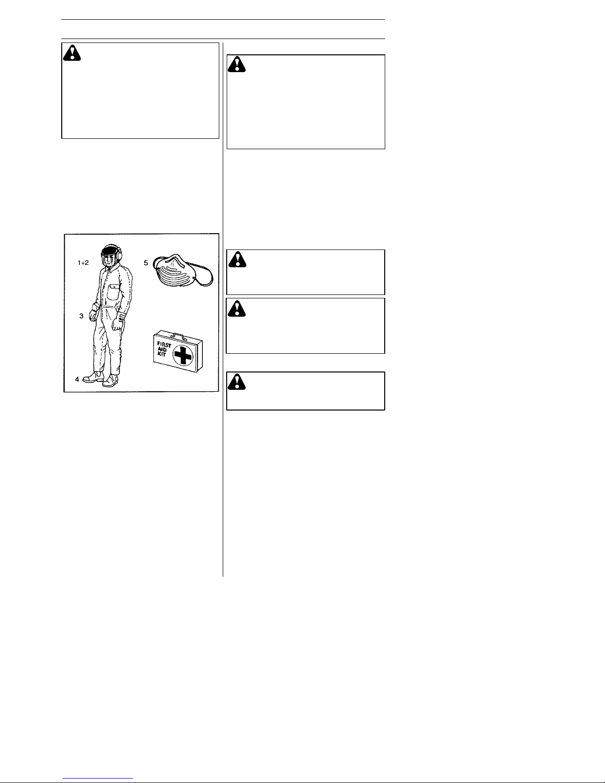
Personal safety equipment
Persons who use the blower shall wear the
following safety equipment:
1. Approved ear protection.
2. Approved eye protection.
3. Approved protective gloves.
4. Boots or work shoes with a non--slip sole.
5. Face mask when operating the blower in
dusty environments.
Personal safety
The following instructions apply to persons
operating the blower:
S The operator shall have read and under-
stood the contents of this manual.
S Do not wear loose clothing, scarves or
neckchains or let long hair hang loose,
since these can be drawn into rotating
parts of the blower and cause injury.
S Do not operate the blower while under
the influence of alcohol, drugs or when
you are tired.
S Do not allow minors to operate the
blower.
S Always have a first aid kit nearby.
WARNING:The fuel used to run
the blower has the following
dangerous characteristics:
1. Vola tile liquid: its vapor and
exhaust fumes are poisonous.
2. Direct contact can cause skin
irritation.
3. It is extremely flammable.
WARNING: Mufflers fitted with
catalytic converters become extremely hot during use and after stopping.
This also applies at idling speeds.
Contact can result in burns to the
skin.Beawareoftheriskoffire!
WARNING: The blower must
never be used if any of the safety
devices or guards are missing,
damaged or not in working order.
WARNING: This machine pro-
duces an electromagnetic field du
ring operation. Under some circumstances, this field may interfere with
active or passive medical implants.
To reduce the risk of serious or fatal
injury, we recommend persons with
medical implants to consult their
physician and the medical implant
manufacturer before operating this
machine.
Page 5

English---5
115278026 Rev. 2 5/1/10
SAFETY INSTRUCTIONS
Other safety measures
S Operate the blower only at reasonable
hours, i.e. not early in the morning or late
at night when people might be disturbed.
Comply with times listed in local ordinances. Usual recommendations are 9:00
a.m. to 5:00 p.m., Monday through Saturday.
S Operate the blower at the lowest possible
throttle setting to do the job.
S Check the condition of the blower before
operation, especially the muffler, air intake
and air filter.
S Use a rake or a broom to loosen ground
debris before blowing.
S Under dusty conditions, slightly spray the
work area with a hose.
S Conserve water by using blowers instead
of hoses for many lawn and garden
applications, including areas such as roof
gutters, screens, patios and gardens etc.
S Watch out for children, pets, open windows
or vehicles, and blow debris safely away.
S Use the full nozzle extension so the air
stream can work close to the ground.
S After using the blower, clean up and
dispose of debris in trash receptacles.
Safety while operating the
blower
S This garden blower/vacuum is only
designed for blowing away or removal of
leaves and other debris on the ground.
S Do not allow bystanders or animals to be
in the work area, i.e. 15 meters from the
operator.
S The blower may throw objects at high
velocity that can ricochet and hit the operator. This may cause serious eye damage.
S Never point the blower nozzle toward
people or animals.
S Stop the engine before fitting or disman-
tling accessories or other components.
S Never operate the blower if any of the
guards are missing.
S Never operate the blower in poorly venti-
lated spaces where exhaust fumes might
otherwise be inhaled.
S Stop the engine before refueling. Move
the unit at least 3 meters from fueling site
before attempting to start.
S The catalytic muffler is extremely hot
while the blower is running and after it
has stopped. The same applies when the
blower is running at idling speed. Be
aware of the danger of fire, especially
while operating the blower near flammable materials and/or where flammable
fumes are present.
S Be careful, particularly if left hand opera-
tion is applied. Avoid any direct body
contact with inlet cover area. Keep jewelry, loose clothing, or clothing with loosely
hanging straps, ties, tassels, etc., away
from inlet cover area.
S Do not operate the blower while standing
on a ladder or a stand.
S Secure the machine during transport.
Page 6
English---6
115278026 Rev. 2 5/1/10
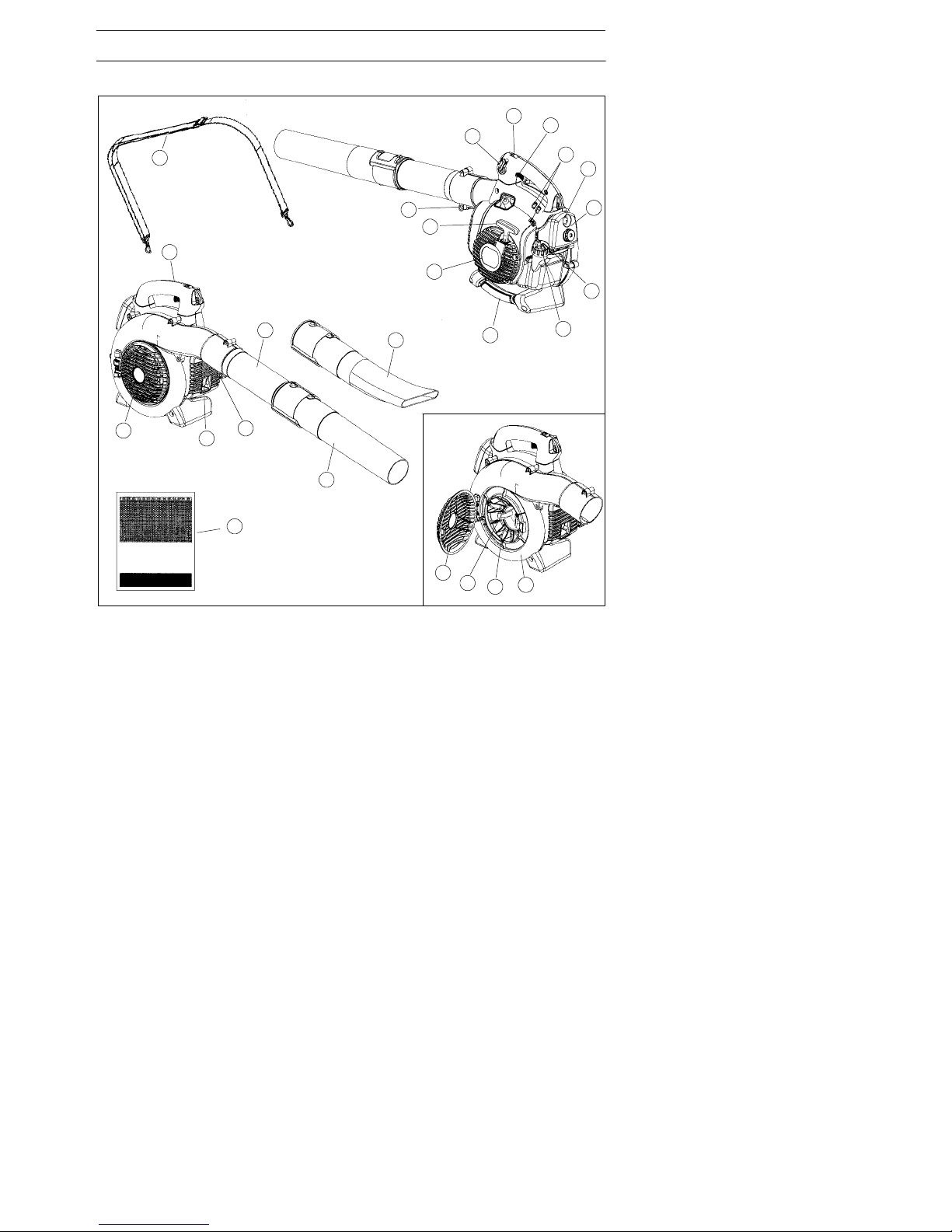
DESCRIPTION
The blower
20
23
24
13
15
14
17
19
12
10
9
8
6
3
1
4
7
11
2
1. Shoulder strap (BV2126) 13. Fan impeller
2. Throttle trigger 14. Standard nozzle
3. STOP switch 15. High velocity nozzle (BV2126)
4. Variable speed control 16. Blower tube
5. Fan housing 17. Tube clamp bolt
6. Fuel cap 18. Tube clamp nuts
7. Air filter 19. Muffler
8. Choke 20. Ground wire
9. Primer bulb 21. Starter handle
10. Inlet cover 22. Starter device
11. Vacuum handle (BV2126) 23. Carburetor adjustment screws
12. Cutters (BV2126) 24. Operator’s manual
5
10
21
16
22
18
Page 7

English---7
115278026 Rev. 2 5/1/10
DESCRIPTION
Accessories (BV2126)
24
22
21. Vacuum device with collection components consisting of items 22--26 below
22. Collection bag tube
23. Collection bag
24. Vacuum tube in two sections
25. Screw
26. Shoulder strap
23
21
25
26
Page 8

English---8
115278026 Rev. 2 5/1/10
DESCRIPTION
Safety equipment
The following equipment on the blower is
designed for protecting personnel and
materials. These components should
receive special attention whenever you
operate, inspect and service the blower.
Stop switch
S The stop switch (A) is used to stop the
engine.
Muffler
S The muffler is designed to give the low-
est possible noise level and to direct the
engine’s exhaust fumes away from the
operator. Mufflers fitted with catalytic
converters are also designed to reduce
harmful exhaust components.
S The engine exhaust fumes are hot and
can contain sparks, which may cause
fire if they come in contact with dry or
flammable material.
S Some blower models, esp. those sold in
countries where the climate is dry, are
equipped with a spark arresting screen
(B). This screen must be cleaned or replaced at specific intervals. See the
Maintenance section.
A
WARNING: The muffler is ex-
tremely hot while the engine is running and after it has stopped. DO
NOTTOUCHTHEMUFFLERIFITIS
HOT! This can cause severe burns.
B
Oth
er equipment
Throttle trigger
S The speed and the output of the engine
are regulated by the throttle trigger (C).
Variable speed control
S The variable speed control (D) is de-
signed to allow setting engine speed as
necessary during blower use only.
S To avoid causing damage to the unit, DO
NOT attempt to use the variable speed
control during starting or during vacuum
use.
Fan housing
S The blower fan housing (E) and the fan
impeller (F) provide high performance air
discharge.
C
E
F
D
Page 9

English---9
115278026 Rev. 2 5/1/10
DESCRIPTION
S The nozzles (L)have a bayonet mount
for connection to the blower tube. Air is
channeled through the blower tube to the
nozzles, where the air discharge velocity
increases and the air stream discharge
pattern is formed to provide best performance. The length of the blower tube
can be adjusted by twisting the nozzle to
the left to disengage the bayonet mount
and sliding the nozzle to the appropriate
position. T wist the nozzle to the right until
a click is felt to resecure the nozzle.
Starterdevice and starter handle
S The starter device (M) is located on the
side of the engine shrouding and engages the crankshaft only when the
starter handle (N) is pulled.
Fuel cap
S The fuel cap (O) is located at the rear of
the engine shrouding on the fuel tank
and has a seal to prevent fuel from leaking out.
Air filter
S The air filter (P) consists of a fiber filter
medium in a resilient frame. The air filter
should be cleaned at specific intervals
(see Maintenance section). Otherwise,
the blower will consume too much fuel,
the performance will be reduced and an
oily deposit may form on the spark plug
electrodes.
Ground wire
S The ground wire (G) reduces static
build--up during operation in dry conditions.
Inlet cover
S An inlet cover (H) is located on the side
of the fan housing. Opening this cover
allows access for cleaning and inspecting the impeller (BV2126 only). If the
vacuum tube is used, it must be fitted to
the opening in the inlet cover. To open
the inlet cover, use a tool to lift the edge
of the cover
opposite the hinge (indicated by arrow
on inlet cover).
Cutters (BV2126)
S Two cutters (J) are fastened to the impel-
ler. The cutters are there to mulch leaves
and other debris that have been vacuumed
before they enter the collection bag.
Blower tube and nozzle
S The blower tube (K) has a pegged slot
mounting system to the unit.Toinstall
or remove the blower tube (or collection
bag tube for the 125BV
X--SERIES
), loosen
the tube clamp bolt (do not remove nuts
from bolt). Align slot in the blower air
outlet with the raised rib on the tube
and insert tube. Tighten tube clamp bolt.
WARNING: Never start the blower
if the inlet cover is not closed, is
damaged or cannot be closed
(except if the vacuum tube is fitted).
H
K
J
M
N
O
P
G
L
Page 10

English---10
115278026 Rev. 2 5/1/10
DESCRIPTION
Adjusting the c arburetor
NOTFORALLMODELS
S There are three adjusting screws (R) for
adjusting the carburetor:
S Low speed jet
S High speed jet
S Adjustment screw for idling
S Adjusting the carburetor involves adapt-
ing the engine to local operating conditions, e.g. climate, altitude, gasoline and
type of two--stroke engine oil used. For
details about carburetor adjustment, see
the Maintenance section.
R
Choke
S The choke (Q) is located below the air
filter cover and should be used every
time the engine is cold--started.
Q
Page 11

English---11
115278026 Rev. 2 5/1/10
FUEL HANDLING
Fuel mixture
CAUTION! The machine is equipped with
a two--stroke engine and must always be
run using a mixture of petrol and two-stroke engine oil. It is important to accurately measure the amount of oil to be
mixed to ensure that the correct mixture is
obtained. When mixing small amounts of
fuel, even small inaccuracies can drastically affect the ratio of the mixture.
Petrol
CAUTION! Always use a good quality
petrol/oil mixture (at least 90 octane).
Use low--emission petrol, also known as
alkylate petrol, if it is available.
S The lowest octane recommended is 90.
If you run the engine on a lower octane
than 90, it can result in knocking. This
gives rise to a high engine temperature,
which can result in serious engine damage.
S When working at continuous high revs, a
higher octane rating is recommended.
Two- -stroke oil
S For best results and performance, use
JONSERED two--stroke oil, which is
specially formulated for our two--stroke
engines. Mixture 1:50 (2%).
S If JONSERED two--stroke oil is not avail-
able, you may use another two-stroke oil of
good quality that is intended for air cooled
engines. Contact your dealer when selecting an oil. Mixing ratio 1:33 (3%).
S Never use two--stroke oil intended for
water--cooled outboard engines,
sometimes referred to as outboard oil.
S Never use oil intended for four--stroke
engines.
WARNING: Always ensure
there is adequate ventilation when
handling fuel.
S
A
lways start byfilling halfthe amount o
f
the gasoline to be used. Then add the
entire amount of oil. Mix (shake) the fuel
mixture. Add the remaining amount of
gasoline.
S Mix (shake) the fuel mixture thoroughly
before filling the machine’s fuel tank.
S Do not mix more than one month’s sup-
ply of fuel at a time.
S If the machine is not used for some time,
the fuel tank should be emptied and
cleaned.
WARNING: The catalytic con-
verter muffler gets very hot during
and after use. This also applies
during idling. Be aware of the fire
hazard, especially when working
near flammable substances and/or
vapors.
Fueling
WARNING: Taking the following
precautions, will lessen the risk of
fire:
Do not smoke or place hot objects
near fuel.
Always shut off the engine before
refueling.
Always stop the engine and let it
cool for a few minutes before
refueling.
When refueling, open the fuel cap
slowly so that any excess pressure
is released gently.
Tighten the fuel cap carefully after
refueling.
Always move the machine away
from the refueling area before
starting.
Mixing
S Always mix the gasoline and oil in a
clean container intended for fuel.
Petrol,
litre
Two --stroke oil, litre
2% (1:50) 3% (1:33)
50,100,15
10 0,20 0,30
15 0,30 0,45
20 0,40 0,60
Page 12

English---12
115278026 Rev. 2 5/1/10
STARTING AND STOPPING
Pull starter handle until engine attempts to
run, but no more than 3 pulls. Move choke
to ½ position and pull the cord until the engine starts and runs. Allow the engine to
warm up for approximately 10 seconds;
then, move the choke to the OFF CHOKE
(opened) position.
NOTE: If engine dies, return blue engine
choke lever to the closed position and
repeat starting steps.
Warm engine
With a warm engine, squeeze and hold the
throttle trigger. Move choke to ½ position.
Pull starter rope sharply while squeezing
throttle trigger until engine runs. Move the
choke to the OFF CHOKE (opened)
position.
Stopping
To stop the engine, push and release the
engine STOP switch (S). The switch will
automatically return to the ON position.
Wait 7 seconds before attempting to restart
unit to allow switch to reset.
Starting and stopping
Cold engine
Primer bulb: Press the primer bulb 10
times until fuel begins to fill the bulb. The
primer bulb need not be completely filled.
Choke: Move the blue engine choke lever
over to the FULL CHOKE (closed) position.
Starting: Hold the body ofthe machine on
the ground using your left hand
(CAUTION! Not with your foot!).
Firmly grip the starter rope handle with
your right hand. DO NOT squeeze
throttle trigger. Slowly pull out the cord
until you feel some resistance (the starter
pawls grip); then quickly and powerfully
pull the cord.
CAUTION! Do not pull the starter cord all
the way out and do not let go of the starter
handle when the cord is fully extended.
This can damage the machine.
WARNING: Never start the blower
if the inlet cover is not closed, is
damaged or cannot be closed
(except if the vacuum tube is fitted).
S
WARNING: Never wrap the starter
cord around your hand.
S Clean the area around the fuel cap.
Contamination in the tank can cause
operating problems.
S Ensure that the fuel is well mixed by shak-
ing the container before filling the tank.
Min. 10 ft.
(3 m)
Page 13

English---13
115278026 Rev. 2 5/1/10
USING THE BLOWER
BV2126 can be used with a shoulder strap
for extra comfort. The strap should be
worn over the shoulder as shown.
To blow away debris on the
ground
Fitting the blower tube and noz z le
on the blower
The blower tube (T) has a pegged slot
mounting system to the unit. To install
or remove the blower tube (or collection
bag tube for the 125BV
X--SERIES
), loosen
the tube clamp bolt (do not remove nuts
from bolt). Align slot in the blower air
outlet with the raised rib on the tube
and insert tube. Tighten tube clamp bolt.
The nozzles (U) have a bayonet mount for
connection to the blower tube. Air is channeled through the blower tube to the
nozzles, where the air discharge velocity
increases and the air stream discharge pattern is formed to provide best performance.
The length of the blower tube can be adjusted by twisting the nozzle to the left to
disengage the bayonet mount and sliding
the nozzle to the appropriate position.
Twist the nozzle to the right until a click is
felt to re--secure the nozzle.
Blowing
Before you begin blowing, put on the required safety equipment.
WARNING: When fitting the blow-
er tube and nozzle, the engine must
be switched off.
U
T
WARNING: When working with
the blower, wear the required personal safety equipment:
1. Hearing protection.
2. Eye protection.
3. Protective gloves.
4. Face mask in dusty environments.
WARNING: Never point the blower
nozzle at people or animals. The
high--velocity air stream can contain
particles that may cause serious
injury, especially if the blower has
previously been used for vacuuming.
Be careful, particularly if left hand
operation is applied. Avoid any direct body contact with inlet cover
area. Keep jewelry, loose clothing,
or clothing with loosely hanging
straps, ties, tassels, etc., away from
inlet cover area.
Page 14

English---14
115278026 Rev. 2 5/1/10
USING THE BLOWER
1. Open the collection bag. Insert the
collection bag tube from inside the bag to
fit in the vacuum inlet opening of the bag
as shown. Ensure elastic is seated in
groove. Close the zipper on the bag.
2. Remove the blower tube and install the
collection bag tube. Tighten tube clamp
bolt. Attach the carrying strap to the
collection bag loops.
3. Align arrows on lower vacuum tube and
upper vacuum tube. Pushlo wer vacuum
tube into upper vacuum tube until the lower
tube is securely seated in the upper tube
(about 3 inches/7 cm). Permanently assemble the two tubes together with the
supplied screw.
4. Open the cover on the side of the blower
by using a screwdriver to pry up under the
edge of the cover on the side opposite the
hinge (indicated by arrow on inlet cover).
5. Press the vacuum tubes in the large
opening at the underside of the blower
and align the tabs with the slots in the
tube. Turn it until the bayonet mount
locks (lock symbols align).
Start the blower as described in the Starting
and Stopping section. Work according to the
following instructions:
1. Never blow air toward fixed objects such
as walls, large rocks, automobiles and
fences.
2. When working inside corners, blow from
the corner and inward toward the center of
the work area. Otherwise, debris can fly
up in your face and cause eye injury.
3. Never point the blower nozzle at delicate
plants.
Standard nozzle
The standard nozzle (V) is included with
the B2126 and BV2126. When greater accuracy and high air stream concentration is
desired, use the standard nozzle.
High--velocity nozzle
The high--velocity nozzle (W) is an accessory of the blower (included with the
BV2126).
When a wider air stream and greater air
velocity is desired, use the high--velocity
nozzle.
To vacuum debris from the
ground (BV2126)
Fitting the collection bag with the
various vacuum tubes
The vacuuming device is an accessory (included with the BV2126).
W
WARNING: When fitting the
tubes to the blower, the engine
must be switched off.
WARNING: Never start the blower
if the inlet cover is not closed, is
damaged or cannot be closed
(except if the vacuum tube is fitted).
WARNING: Do not operate the
blower while standing on a ladder or
a stand.
V
Page 15

English---15
115278026 Rev. 2 5/1/10
USING THE BLOWER
When operating the blower, the collection
bag must be supported by the shoulder
strap. The strap should be worn over the
shoulder as shown.
WARNING: Always check that
the collection bag is intact and the
zipper is closed before starting the
blower. Never use a damaged bag.
There is risk of injury due to flying
debris. Be careful, particularly if left
hand operation is applied. Avoid any
direct body contact with the exhaust outlet area.
WARNING: Never start the blower
if the inlet cover is not closed, is
damaged or cannot be closed
(except if the vacuum tube is fitted).
WARNING: Do not operate the
blower while standing on a ladder or
a stand.
Start the blower as described in the Starting
and Stopping section. Work according to the
following instructions:
1. Do not vacuum large solid objects that
can damage the fan, such as wood, cans
(tins) or lengths of string or ribbon.
2. Do not let the vacuum tube strike the
ground.
3. The collection bag can be emptied by first
stopping the unit and then opening the zipper on the side.
Vacuuming
Before vacuuming, put on the required
safety equipment.
WARNING: When working with
the blower, wear the required personal safety equipment:
1. Hearing protection.
2. Eye protection.
3. Protective gloves.
4. Face mask in dusty environments.
Page 16

English---16
115278026 Rev. 2 5/1/10
MAINTENANCE
Muffler
Some mufflers are fitted with catalytic converters. See the Technical data section to
find out if your machine is equipped with a
catalytic converter.
The muffler is designed to dampen the
noise level and to direct the exhaust fumes
away from the user. The exhaust fumes
are hot and can contain sparks, which can
result in fire if the exhaust fumes are
directed towards a dry and flammable
material.
Some mufflers are equipped with a special
spark arresting screen(Y). If your machine
is fitted with this type of screen, it should
be cleaned regularly. Toaccess the
screen, remove the outlet cover on the
front of the muffler. Use a wire brush to
clean the screen. On mufflers without a
catalytic converter the screen should be
cleaned weekly, or replaced if necessary.
On mufflers fitted with a catalytic converter
the screen should be checked and cleaned
monthly. If the screen is damaged it
should be replaced. If the screen is frequently blocked, this can be a sign that the
function of the catalytic converter is impaired. Contact your dealer to inspect the
muffler.A blocked screen will cause the
engine to overheat resulting in damage to
the cylinder and piston.
Carburetor
Y our Jonsered product has been designed
and manufactured to specifications that reduce harmful emissions. After the engine
has used 8--10 tanks of fuel, the engine will
be run--in. To ensure that it continues to run
at peak performance and to minimize harmful exhaust emissions after the run--in period, ask your servicing dealer to adjust your
carburetor.
Function
S The carburetor governs the engine’s
speed via the throttle control. Air and fuel
are mixed in the carburetor.
S The T--screw (X) regulates the throttle
setting at idle speed. If the T--screw is
turned clockwise this gives a higher idle
speed; turning it counterclockwise gives a
lower idle speed.
Basic setting
S The basic carburetor settings are ad-
justed during testing at the factory. Fine
adjustment should be carried out by a
skilled technician.
Recommended idle speed:
See “Technical data” section.
Recommended max. speed:
See “Technical data” section.
Fine adjustment of the idle speed--T
Adjust the idle speed using the idle adjustment T--screw if it is necessary to readjust.
The idle speed is correctly adjusted when
the engine will run smoothly in every position.
X
CAUTION! Never use a machine that has
a faulty or loose muffler. Ensure the muffler
bolts are tight.
Maintenance Safety
The owner is responsible for the performance of all required maintenance as
defined in the operator’s manual.
Disconnect the spark plug before performing maintenance, except carburetor adjustments.
Page 17

English---17
115278026 Rev. 2 5/1/10
MAINTENANCE
Air filter
The air filter (CC) must be regularly cleaned
to remove dust and dirt in order to avoid:
S Carburetor malfunctions
S Starting problems
S Loss of engine power
S Unnecessary wear to engine parts
S Excessive fuel consumption
S Elevated content of harmful exhaust
fumes.
Clean the filter every 25 hours, or more
regularly if conditions are exceptionally
dusty.
Cleaning the air filter
Remove the air filter cover (DD) and take out
the filter. Wash it clean in warm, soapy water.
Rinse thoroughly. Ensure that the filter is dry
before reinstalling it.
An air filter that has been in use for a long
time cannot be cleaned completely. The
filter must therefore be replaced with a new
one at regular intervals.
CAUTION! A damaged air filter must
always be replaced.
Cooling system
The engine is equipped with a cooling
systemformaintaining the right operating
temperature.
The cooling system consists of the following components:
1. Air intake on the starter device (Z).
2. Fan blades on the flywheel (AA).
3. Cooling fins on the cylinder (BB).
4. Cylinder cowling (guides cooling air flow
against cylinder surfaces).
Clean the cooling system by brushing once
a week, or more often, if necessary.
A dirty or blocked cooling system will
cause the blower to overheat and this will
damage the cylinder and piston.
WARNING: Mufflers fitted with
catalytic converters get very hot
duringuseandremainsoforsome
time after stopping. This also applies at idle speed. Contact can result in burns to the skin. Remember
theriskoffire!
WARNING: The inside of the
muffler contain chemicals that may
be carcinogenic. Avoid contact with
these elements in the event of a
damaged muffler.
WARNING: Bear in mind that:
Engine exhaust fumes contain carbon monoxide, which can cause
carbon monoxide poisoning. For
this reason you should not start or
run the machine indoors, or anywhere that is poorly ventilated.
The exhaust fumes from the engine
are hot and may contain sparks
which can start a fire. Never start
the machine indoors or near flammable material!
Y
Z
AA
BB
CC
DD
Page 18

English---18
115278026 Rev. 2 5/1/10
MAINTENANCE
Spark plug
The spark plug condition is influenced by:
S Incorrect carburetor adjustment.
S An incorrect fuel mixture (too much or in-
correct type of oil).
S Poor quality gasoline and/or oil
S A dirty air filter.
These factors cause deposits on the spark
plug electrodes, which may result in operating problems and starting difficulties.
If the machine is low on power, difficult to
start or runs poorly at idle speed: always
check the spark plug first before taking
any further action. If the spark plug is dirty,
clean it and check that the electrode gap is
0,6 mm. The spark plug should be replaced
after about a month in operation or earlier if
necessary.
0,6 mm
CAUTION! Always use the recommended
spark plug type! Use of the wrong spark
plug can damage the piston/cylinder.
Maintenance schedule
Below you will find some general maintenance instructions.
Daily maintenance
S Clean the exterior surfaces of the blower.
S Check that the variable speed control and
the throttle trigger function in a safe manner. Replace damaged parts.
S Check that the stop switch works proper-
ly. Replace if necessary.
S Clean the air filter.Replace if necessary.
S BV2126: Check that the inlet cover can
be locked in the closed position. Carefully
check that the fan impeller is clean, especially if the blower has been used for collecting debris (vacuuming).
S Check that all nuts and screws are prop-
erly tightened.
S Check that all the housings are free of
cracks. Replace damaged parts.
S BV2126: Check that the collection bag is
intact and that the zipper works. Replace
it if necessary.
Weekly maintenance
S Check the condition of the starter device,
the starter cord and the tensioning spring.
Replace damaged parts.
S Check the condition of the air intake at
the starter device. Remove debris if it is
clogged.
S Clean the outside of the spark plug. Re-
move it and check the electrode gap. Adjust the gap to 0,6 mm, or replace the
spark plug. Use resistor spark plug
Champion RCJ--8Y or equivalent.
S Clean the fan blades on the flywheel.
S Clean or replace the spark arresting
screen (not on mufflers with a catalytic
converter).
S Clean the carburetor area.
S Clean the air filter.
Monthly maintenance
S Clean the fuel tank.
S Clean the outside of the carburetor and
the area around it.
S Clean the fan blades on the flywheel and
the area around it.
S Check fuel lines for cracks or other dam-
age. Change if necessary.
S Change the fuel filter in fuel tank.
S Check all cables and connections. Re-
place damaged parts.
S Replace the spark plug. Use spark plug
Champion RCJ--8Y or equivalent.
S Change the air filter.
Page 19

English---19
115278026 Rev. 2 5/1/10
TECHNICAL DATA
Technical data
B2126 BV2126
Engine
Cylinder volume, cm
3
28 28
Cylinder bore, mm 35 35
Stroke, mm 28,7 28,7
Idle speed, rpm 2800--3200 2800--3200
Max. speed - blowing, rpm: 8600 8600
Max. speed - vacuuming, rpm: ---- 7500
Max. engine output, acc. to ISO 8893, kW 0,8 0,8
Catalytic converter muffler Yes Yes
Ignition system
Spark plug ChampionRCJ--6Y ChampionRCJ--6Y
Electrode gap, mm 0,6 0,6
Fuel and lubrication system
Fuel tank capacity, liter 0,5 0,5
Weight
Weight, without fuel but with blower tube
and standard nozzle fitted, kg 4,3 4,4
Noise emissions
(see note 1)
Sound power level, measured dB(A) 106 106
Sound power level, guaranteed L
WA
dB(A) 107 107
Noise levels
(see note 2)
Equivalent sound pressure level at the
operators’ ear,measured according to
ISO 22868, dB(A)
Equipped with blower tubes and
nozzle (original) 94 99
Equipped with vacuum tubes (original) ---- 99
Vibration levels
(see Note 3)
Equivalent vibration levels (a
hv,eq
) at handles,
measured according to ISO 22867, m/s
2
Equipped with blower tubes and
nozzle (original) 8,3 8,3
Equipped with vacuum tubes (original),
left/right ----/---- 6,4/8,3
Note 1: Noise emissions in the environment measured as sound power (L
WA
) in conformity with EC directive 2000/14/EC. Reported sound power level for the machine has been
measured with the original cutting attachment that gives the highest level. The difference
between guaranteed and measured sound power is that the guaranteed sound power also
includes dispersion in the measurement result and the variations between different machines of the same model according to Directive 2000/14/EC.
Note 2: Reported data for equivalent sound pressure level for the machine has a typical
statistical dispersion (standard deviation) of 1 dB(A).
Note 3: Reported data for equivalent vibration level has a typical statistical dispersion
(standard deviation) of 1 m/s
2
.
Fan B2126 BV2126
Type Radial fan Radial fan
Max.airvel ocity, m/ s (km/ h), standa rd nozzle 60 (217) 60 (217)
Max.airvel ocity, m/ s (km/ h), high velocity nozzle* 76 (273) 76 (273) 76 (273)
Air volume -- blowing, m
3
/h (cfm) 722 (425) 722 (425)
Air volume -- vacuuming, m
3
/h (cfm) ---- 756 (445)
*optional accessory for some models
Page 20

English---20
115278026 Rev. 2 5/1/10
TECHNICAL DATA
Model B2126
Approved accessories Part. no.
High velocity nozzle 545 119 502
DECLARATION OF CONFORMITY
EC Declaration of Conformity (Only applies to Europe)
We, Husqvarna AB, SE-561 82 Huskvarna, Sweden, tel: +46--36--146500, as authorised
representative in the Community, declare that the garden blower/vacuum models Jonsered
B2126 and BV2126 with serial numbers dating from 2009 and onwards (the year is clearly
stated on the rating plate,followed by the serialnumber),complywith therequirements ofthe
COUNCIL’S DIRECTIVES:
of 17 May 2006 “relating to machinery” 2006/42/EC;
of15 December 2004“relatingto electromagnetic compatibility”2004/108/EC,and applicable
supplements; and
of 8May2000“relatingtothenoise emissions in theenvironment” in accordance with Annex
Vof2000/14/EC. For information relating to noise emissions, see Technical data section.
The following standards have been applied: EN ISO 12100-1/A1:2009, EN ISO
12100-2/A1:2009, CISPR 12:2007.
SMP, The Swedish Machinery Testing Institute, Fyrisborgsgatan 3 S--754 50 Uppsala,
Sweden, has performed voluntary type examination on behalf of Husqvarna AB. The
certificate(s) are numbered: SEC/09/2023.
09-- 11 -- 01
Ronnie E. Goldman, Director of Engineering
Authorized representative for Husqvarna AB and
responsible for technical documentation
 Loading...