

Page 1
P
OWERTECH
4.5 and 6.8 L
4045 and 6068
Tier 2 / Stage II
OEM Diesel Engines
OPERATOR’S MANUAL
P
OWERTECH
Stage II OEM Diesel Engines
4.5 and 6.8 L Tier 2 /
OMRG33324 Issue 7Aug06 (ENGLISH)
CALIFORNIA
Proposition 65 Warning
Diesel engine exhaust and some of its constituents are
known to the State of California to cause cancer, birth
defects, and other reproductive harm.
If this product contains a gasoline engine:
WARNING
The engine exhaust from this product contains chemicals
known to the State of California to cause cancer, birth
defects or other reproductive harm.
The State of California requires the above two warnings.
John Deere Power Systems
LITHO IN U.S.A.
Page 2

Foreword
Introduction
THIS MANUAL CONTAINS INFORMATION to operate
and service the following Tier 2 / Stage II
emission-certified1engines:
Saran-built (France) Tier 2 Mechanically Controlled
Engines:
• CD4045DF270
• CD4045TF270
Saran-built (France) Tier 2 Electronically Controlled
Engines:
• CD4045TF275 (DE10 Fuel System)
• CD4045HF275 (DE10 Fuel System)
• CD4045HF475 (HPCR System; 4-Valve Head)
• CD6068TF275 (DE10 Fuel System)
• CD6068HF275 (DE10/VP44 Fuel System)
• CD6068HF475 (HPCR System; 4-Valve Head)
Torreon-built (Mexico) Tier 2 Mechanically Controlled
Engines:
• PE4045DF270
• PE4045TF270
• PE6068HF475 (HPCR System; 4-Valve Head)
READ THIS MANUAL carefully to learn how to operate
and service your engine correctly. Failure to do so
could result in personal injury or equipment damage.
THIS MANUAL SHOULD BE CONSIDERED a
permanent part of your engine and should remain with
the engine when you sell it.
MEASUREMENTS IN THIS MANUAL are given in both
metric and customary U.S. unit equivalents. Use only
correct replacement parts and fasteners. Metric and
inch fasteners may require a specific metric or inch
wrench.
WRITE ENGINE SERIAL NUMBERS and option codes
in the spaces indicated in the Record Keeping Section.
Accurately record all the numbers. Your dealer also
needs these numbers when you order parts. File the
identification numbers in a secure place off the engine.
SETTING FUEL DELIVERY beyond published factory
specifications or otherwise overpowering will result in
loss of warranty protection for this engine.
Torreon-built (Mexico) Tier 2 Electronically Controlled
Engines:
• PE4045TF275 (DE10 Fuel System)
• PE4045HF275 (DE10 Fuel System)
• PE4045HF475 (HPCR System; 4-Valve Head)
• PE6068TF275 (DE10 Fuel System)
• PE6068HF275 (DE10/VP44 Fuel System)
1
Emission certified for United States as EPA Tier 2 and for European
Union as Stage II.
CERTAIN ENGINE ACCESSORIES such as radiator,
air cleaner, and instruments are optional equipment on
John Deere OEM Engines. These accessories may be
provided by the equipment manufacturer instead of
John Deere. This operator’s manual applies only to the
engine and those options available through the John
Deere distribution network.
OURGP11,000006E –19–04AUG06–1/2
080706
PN=2
Page 3

Introduction
IMPORTANT: This manual covers only
P
OWERTECH
Tier 2 / Stage II
emission certified 4.5 and 6.8 L OEM
engines listed. These engines meet
Tier 2 emission certification
standards.2(This is for both the U.S.
EPA and European Union Council
(EU) standards.) Engines with
mechanical controls which are
P
OWERTECH
2
Two exceptions: The 4045HF475 and 6068HF475 for generator
applications at 1500 rpm are still emission non-certified.
is a trademark of Deere & Company.
non-emission certified or Tier 1 /
Stage I emission certified (U.S. and
EU) are covered in a separate
operators manual, OMRG25204.
NOTE: This manual covers engines provided to OEM
(Original Equipment Manufacturers). For
engines in Deere machines, refer to the
machine operator’s manual.
OURGP11,000006E –19–04AUG06–2/2
080706
PN=3
Page 4

Introduction
080706
PN=4
Page 5

Engine Owner
Introduction
John Deere Engine Owner:
Don’t wait until you need warranty or other service to
meet your local John Deere Engine Distributor or
Service Dealer. To register your engine for warranty
via the Internet, use the following URL:
http://www.johndeere.com/enginewarranty
Learn who your dealer is and where he is. At your first
convenience, go meet him. He’ll want to get to know
you and to learn what your needs might be.
Aux Utilisateurs De Moteurs John Deere:
N’attendez pas d’eˆtre oblige´d’avoir recours a`votre
concessionnaire John Deere ou au point de service le
plus proche pour vous adresser a`lui. Pour enregistrer
votre moteur pour la garantie via Internet, utilisez
l’adresse suivante:
http://www.johndeere.com/enginewarranty
Renseignez-vous de`s que possible pour l’identifier et
le localiser. A la premie`re occasion, prenez contact
avec lui et faites-vous connaıˆtre. Il sera lui aussi
heureux de faire votre connaissance et de vous
proposer ses services le moment venu.
An Den Besitzer Des John Deere Motors:
Warten Sie nicht auf einen evt. Reparaturfall, um den
na¨chstgelegenen John Deere Ha¨ndler kennen zu
lernen. Zur Registrierung Ihres Motors fu¨r die Garantie
dient folgende Internet-Adresse:
http://www.johndeere.com/enginewarranty
distributore dei motori John Deere o del
concessionario che fornisce l’assistenza tecnica. Per
registrare via Internet la garanzia del suo motore, si
collegi al seguente sito URL:
http://www.johndeere.com/enginewarranty
Lo identifichi e si informi sulla sua ubicazione. Alla
prima occasione utile lo contatti. Egli desidera fare la
sua conoscenza e capire quali potrebbero essere le
sue necessita`.
Propietario De Equipo John Deere:
No espere hasta necesitar servicio de garantı´aode
otro tipo para conocer a su Distribuidor de Motores
John Deere o al Concesionario de Servicio. Registre
su motor para la garantı´a en la siguiente direccio´nde
internet: http://www.johndeere.com/enginewarranty
Ente´rese de quie´nes,ydo´nde esta´situado. Cuando
tenga un momento, vaya a visitarlo. A e´l le gustara
´
conocerlo, y saber cua´les podrı´an ser sus
necesidades.
Till a¨gare av John Deere motorer:
Ta reda pa˚vem din a˚terfo¨rsa¨ljare a¨r och beso¨k honom
sa˚snart tillfa¨lle ges. Va¨nta inte tills det a¨r dags fo¨r
service eller eventuellt garantiarbete. Din motor
garantiregistrerar Du via Internet pa
˚
http://www.johndeere.com/enginewarranty
Din a˚terfo¨rsa¨ljare vill mycket ga¨rna tra¨ffa dig fo¨r att la¨ra
ka¨nna dina behov och hur ba¨st han kan hja¨lpa dig.
Machen Sie sich bei ihm bekannt und nutzen Sie sein
“Service Angebot”.
Proprietario del motore John Deere:
Non aspetti fino al momento di far valere la garanzia o
di chiedere assistenza per fare la conoscenza del
OURGP11,0000251 –19–27JUL06–1/1
080706
PN=5
Page 6
Introduction
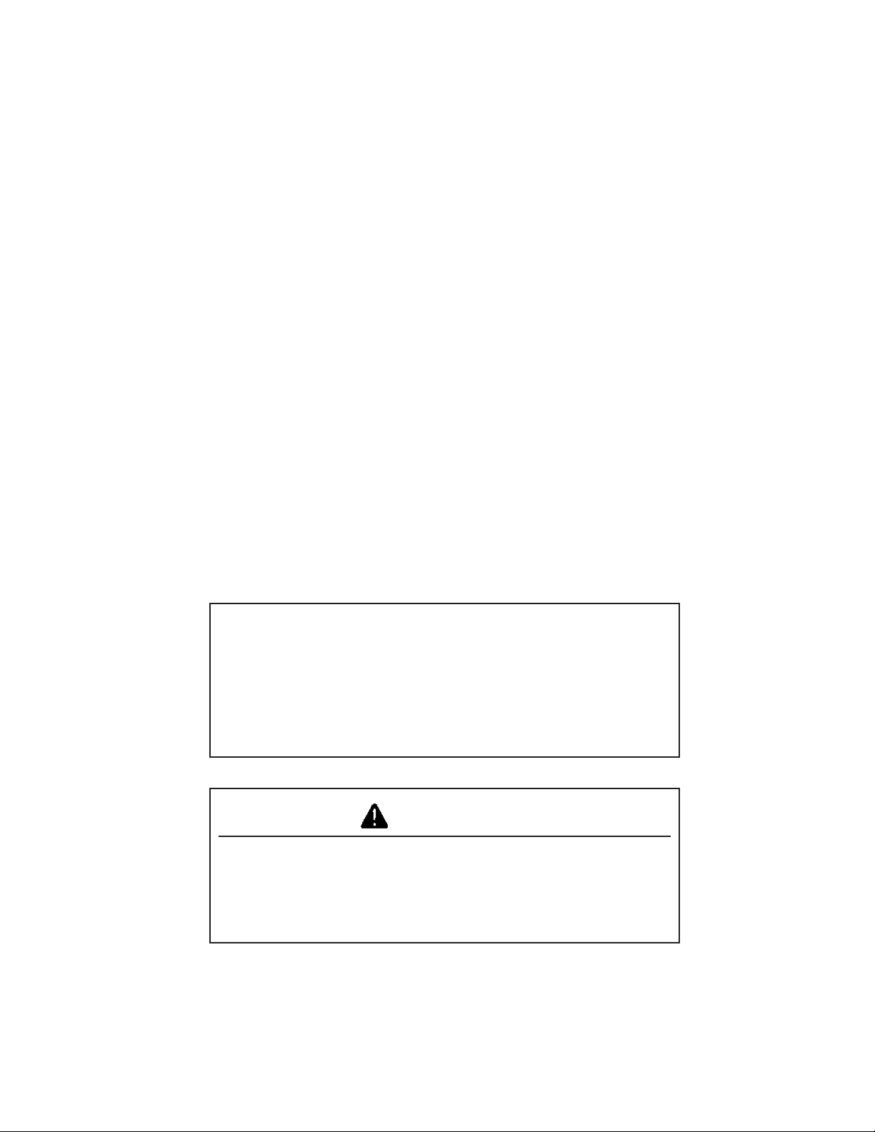
POWERTECH 4.5 L Engines With Electronic Fuel Systems (Tier 2 Emission Certified)
(Two-Valve Cylinder Head Models)
4045 Engine (Stanadyne DE10 Injection Pump Shown)
P
OWERTECH
is a trademark of Deere & Company.
4045 Engine
RG11932 –UN–06NOV01
RG11931 –UN–06NOV01
OUOD002,0000162 –19–04AUG06–1/1
080706
PN=6
Page 7
Introduction
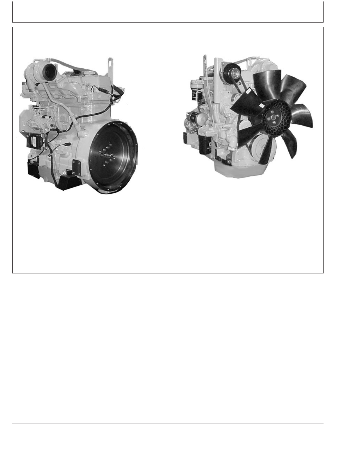
POWERTECH 6.8 L Engines With Electronic Fuel Systems (Tier 2 Emission Certified)
(Two-Valve Cylinder Head Models)
6068 Engine (Bosch VP44 Injection Pump Shown)
P
OWERTECH
is a trademark of Deere & Company.
RG11933 –UN–24OCT01
6068 Engine
RG11934 –UN–24OCT01
OUOD002,0000163 –19–04AUG06–1/1
080706
PN=7
Page 8
Introduction
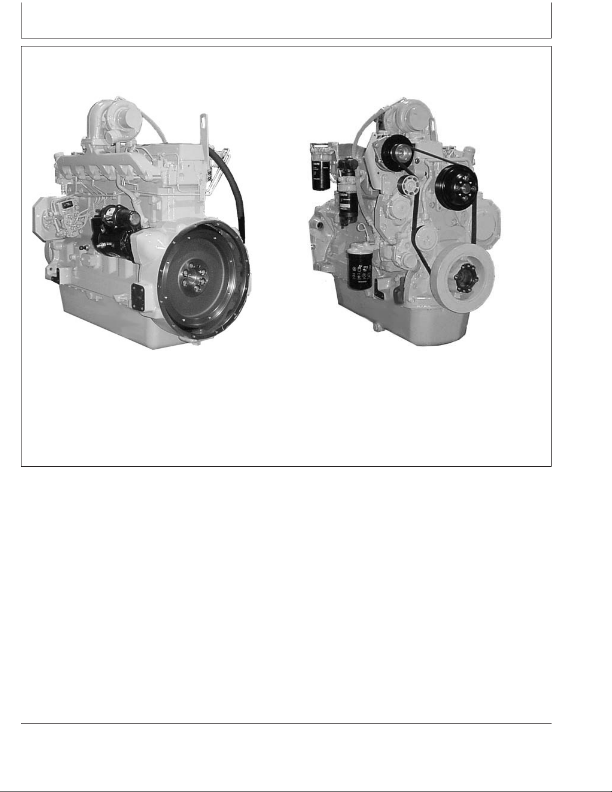
POWERTECH 4.5/6.8 L Engines With Electronic Fuel Systems (Tier 2 Emission Certified)
(Four-Valve Cylinder Head “475” Models)
6068HF475 Engine Shown (Level 11 Electronic Fuel System With
Denso High Pressure Common Rail)
P
OWERTECH
is a trademark of Deere & Company.
RG12199 –UN–24MAY02
6068HF475 Shown
RG12200 –UN–24MAY02
OURGP11,000018B –19–04AUG06–1/1
080706
PN=8
Page 9

Contents
Page
Record Keeping
Engine Serial Number Plate ................01-1
Record Engine Serial Number ..............01-2
Engine Option Codes .....................01-3
Record Engine Control Unit (ECU) Serial
Number..............................01-5
Record Fuel Injection Pump Model Number ....01-5
Safety ................................05-1
Fuels, Lubricants, and Coolant
Diesel Fuel.............................10-1
Lubricity of Diesel Fuel....................10-1
Handling and Storing Diesel Fuel ............10-2
Testing Diesel Fuel.......................10-2
Bio-Diesel Fuel..........................10-3
Minimizing the Effect of Cold Weather on
Diesel Engines ........................10-4
Diesel Engine Break-In Oil .................10-5
Diesel Engine Oil ........................10-6
Diesel Engine Oil and Filter Service Intervals. . . 10-7
Mixing of Lubricants ......................10-9
Oil Filters .............................10-10
OILSCANand COOLSCAN .............10-10
Alternative and Synthetic Lubricants.........10-11
Lubricant Storage.......................10-11
Grease...............................10-12
Diesel Engine Coolant ...................10-13
Drain Intervals for Diesel Engine Coolant ....10-14
Supplemental Coolant Additives............10-15
Testing Diesel Engine Coolant .............10-15
Operating in Warm Temperature Climates ....10-16
Disposing of Coolant ....................10-16
Instrument Panel Identification
Instrument Panels - Identification ............15-1
Instrument Panel - Elect. Cont. Earlier Engines
Instrument Panel ........................16-1
Using Diagnostic Gauge to Access Engine
Information ...........................16-8
Page
Using Touch Switches to Display
Information ..........................16-10PowerTech Medallion.....................01-1
Changing Units of Measure (English or
Metric)..............................16-12
Viewing Engine Configuration Data .........16-14
Viewing Active Engine Service
Codes/Diagnostic Trouble Codes (DTCs) . . . 16-16
Viewing Stored Service
Codes/Diagnostic Trouble Codes
(DTCs) in the Engine ECU ..............16-17
Instrument Panel - Elect. Cont. Later Engines
Instrument Panels........................17-1
Using Diagnostic Gauge to Access Engine
Information ...........................17-4
Main Menu Navigation ....................17-5
Engine Configuration Data .................17-6
Accessing Stored Trouble Codes ............17-8
Accessing Active Trouble Codes ...........17-10
Engine Shutdown Codes .................17-12
Adjusting Backlighting....................17-13
Adjusting Contrast ......................17-15
Selecting Units Of Measurement ...........17-17
Setup 1-Up Display .....................17-20
Setup 4-Up Display .....................17-26
Instrument Panel - Mech. Cont. “270” Engines
Instrument Panel (Earlier 4.5 L “270”
Engines) .............................18-1
Instrument Panel (Later 4.5 L “270” Engines). . . 18-3
Engine Operation - Except 4.5L “270” Engines
Engine Break-In Service...................19-1
Starting the Engine.......................19-4
Normal Engine Operation..................19-7
Warming Engine.........................19-8
Cold Weather Operation...................19-9
Using a Booster Battery or Charger .........19-11
Avoid Excessive Engine Idling .............19-12
Changing Engine Speed..................19-13
Stopping The Engine ....................19-16
Continued on next page
All information, illustrations and specifications in this manual are based on
the latest information available at the time of publication. The right is
reserved to make changes at any time without notice.
COPYRIGHT2006
DEERE & COMPANY
Moline, Illinois
A John Deere ILLUSTRUCTIONManual
Copyright2001, 2002, 2003, 2004, 2006
All rights reserved
Previous Editions
i
080706
PN=1
Page 10

Contents
Page Page
Auxiliary Gear Drive Limitations ............19-17 Checking Crankshaft Vibration Damper
Generator Set (Standby) Applications........19-17
(6-Cylinder Engine Only).................35-2
Flushing and Refilling Cooling System ........35-3
Engine Operation- 4.5 L “270” Engines
Normal Engine Operation..................20-1
Break-In Service.........................20-2
Auxiliary Gear Drive Limitations .............20-3
Generator Set (Standby) Power Units.........20-4
Starting The Engine ......................20-4
Cold Weather Starting ....................20-6
Warming Engine.........................20-8
Avoid Excessive Engine Idling ..............20-9
Testing Thermostats Opening Temperature ....35-6
Check and Adjust Valve Clearance (All
Engines Except 4045HF475 And
6068HF475) ..........................35-9
Check and Adjust Valve Clearance
(4045HF475 And 6068HF475 Engines).....35-12
Test Glow Plugs for Continuity
(4045HF475 And 6068HF475 Engines).....35-15
Stopping the Engine.....................20-10
Using a Booster Battery or Charger .........20-11
Service as Required
Additional Service Information ..............40-1
Do Not Modify Fuel System ................40-2Lubrication and Maintenance
Observe Service Intervals..................21-1
Use Correct Fuels, Lubricants, and Coolant ....21-1
Lubrication and Maintenance Service
Interval Chart—Standard Industrial Engines . . 21-2
Lubrication and Maintenance Service
Interval Chart—Generator (Standby)
Applications ..........................21-4
Lubrication & Maintenance/Daily
Daily Prestarting Checks ..................25-1
Lubrication & Maintenance/500 Hour/12 Month
Servicing Fire Extinguisher.................30-1
Checking Engine Mounts ..................30-1
Servicing Battery ........................30-2
Manual Belt Tensioner Adjustment...........30-4
Manual Belt Tensioner Adjustment Using
Belt Tension Tool (Alternate Method
For Engines Without Auxiliary Drive)........30-5
Changing Engine Oil and Replacing Filter .....30-7
Checking Crankcase Vent System ...........30-9
Checking Air Intake System ...............30-11
Adding Coolant..........................40-3
Replacing Single Stage Air Cleaner ..........40-5
Replacing Axial Seal Air Cleaner Filter
Element .............................40-6
Replacing Radial Seal Air Cleaner Filter
Element .............................40-8
Replacing Fan and Alternator Belts .........40-10
Checking Fuses ........................40-11
Checking Air Compressors................40-11
Bleeding the Fuel System (Engines With
Electronic Fuel Systems And Bosch VP44
Pump)..............................40-12
Bleed the Fuel System (Engines with
Electronic Fuel Systems and Stanadyne DE10
Pump)..............................40-14
Bleed the Fuel System (Engines with
Electronic Fuel Systems and Denso High
Pressure Common Rail) (4045HF475,
6068HF475) .........................40-17
Bleed the Fuel System (4045DF270,
4045TF270) .........................40-19
Replacing Fuel Filter Elements.............30-12
Checking Belt Tensioner Spring Tension
and Belt Wear (Automatic Tensioner) ......30-14
Checking Engine Electrical Ground
Connections .........................30-16
Checking Cooling System.................30-16
Replenishing Supplemental Coolant
Additives (SCAs) Between Coolant
Changes ............................30-17
Testing Diesel Engine Coolant .............30-19
Pressure Testing Cooling System...........30-20
Checking and Adjusting Engine Speeds......30-21
Troubleshooting
General Troubleshooting Information .........45-1
Precautions For Welding On Engines
Equipped With Electronic Engine Control Unit
(ECU) ...............................45-2
Precautions for Electrical System When
Steam Cleaning Engine .................45-2
Engine Wiring Layout (Electronic Fuel
System With Stanadyne DE10 Injection
Pump)...............................45-3
Engine Wiring Layout (Electronic Fuel
System With Bosch VP44 Injection Pump) . . . 45-4Lubrication & Maint./2000 Hour/24 Month
Adjusting Variable Speed (Droop) — 4.5
L “270” Generator Set Engines Only........35-1
Continued on next page
ii
080706
PN=2
Page 11

Contents
Page Page
Engine Wiring Layout (Electronic Fuel Lubrication and Maintenance Records
System With Denso High Pressure Common
Rail)(4045HF475,6068HF475).............45-5
Engine Wiring Diagram (With Earlier
Electronic Instrument Panel) ..............45-6
Engine Wiring Diagram (Engines With
Using Lubrication and Maintenance Records . . . 60-1
Daily (Prestarting) Service .................60-1
500 Hour/12 Month Service ................60-2
2000 Hour/24 Month Service ...............60-3
Service as Required......................60-4
Electronic Instrument Panel) ..............45-7
Engine Wiring Diagram (With Later
Full-Featured Electronic Instrument Panel) . . . 45-8
Engine Wiring Diagram (With Later
Full-Featured Electronic Instrument Panel)—
Emission System Warranty
U.S. EPA Emmission Control Warranty
Statement ............................65-1
Emission Control System Certification Label....65-2
Continued ............................45-9
Engine Troubleshooting ..................45-10
Blink Code Method for Retrieving
Diagnostic Trouble Codes (All Except
Early VP44 Pump Engines)..............45-17
Blink Code Method for Retrieving
Diagnostic Trouble Codes (Early VP44
Pump Engines Only)...................45-18
Instrument Panel Method for Retrieving
Diagnostic Trouble Codes...............45-20
Displaying Of Diagnostic Trouble Codes
(DTCs) .............................45-21
Listing of Diagnostic Trouble Codes (DTCs)
(Engines With Electronic Fuel
Systems And Stanadyne DE10 Pump) .....45-22
Listing of Diagnostic Trouble Codes (DTCs)
(Engines With Electronic Fuel
Systems And Bosch VP44 Pump).........45-24
Listing of Diagnostic Trouble Codes (DTCs)
(Engines With Electronic Fuel Systems
And Denso High Pressure Common Rail) (“475”
Engines) ............................45-26
Error Codes Displayed (With Early
Electronic Panels).....................45-28
Intermittent Fault Diagnostics (With
Electronic Controls)....................45-29
Displaying Diagnostic Gauge Software
(Later Engines) .......................45-29
Storage
Engine Storage Guidelines.................50-1
Preparing Engine for Long Term Storage......50-2
Removing Engine from Long Term Storage ....50-3
Specifications
General OEM Engine Specifications..........55-1
Engine Power Ratings And Fuel System
Specifications .........................55-3
Engine Crankcase Oil Fill Quantities .........55-6
Unified Inch Bolt and Screw Torque Values ....55-7
Metric Bolt and Screw Torque Values.........55-8
iii
080706
PN=3
Page 12

Contents
iv
080706
PN=4
Page 13
Record Keeping
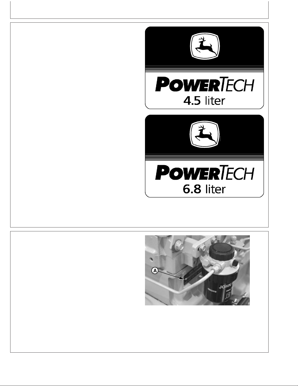
POWERTECH Medallion
A medallion is located on the rocker arm cover which
identifies each engine as a John Deere P
engine.
NOTE: Four-valve head engines also have “16V” or “24V”
printed on their medallions. The 4045HF475 has
“16V” to denote 16 valves total while 6068HF475
has “24V” to denote 24 valves total.
OWERTECH
RG11608 –UN–17OCT01RG11609 –UN–17OCT01
P
OWERTECH
is a trademark of Deere & Company.
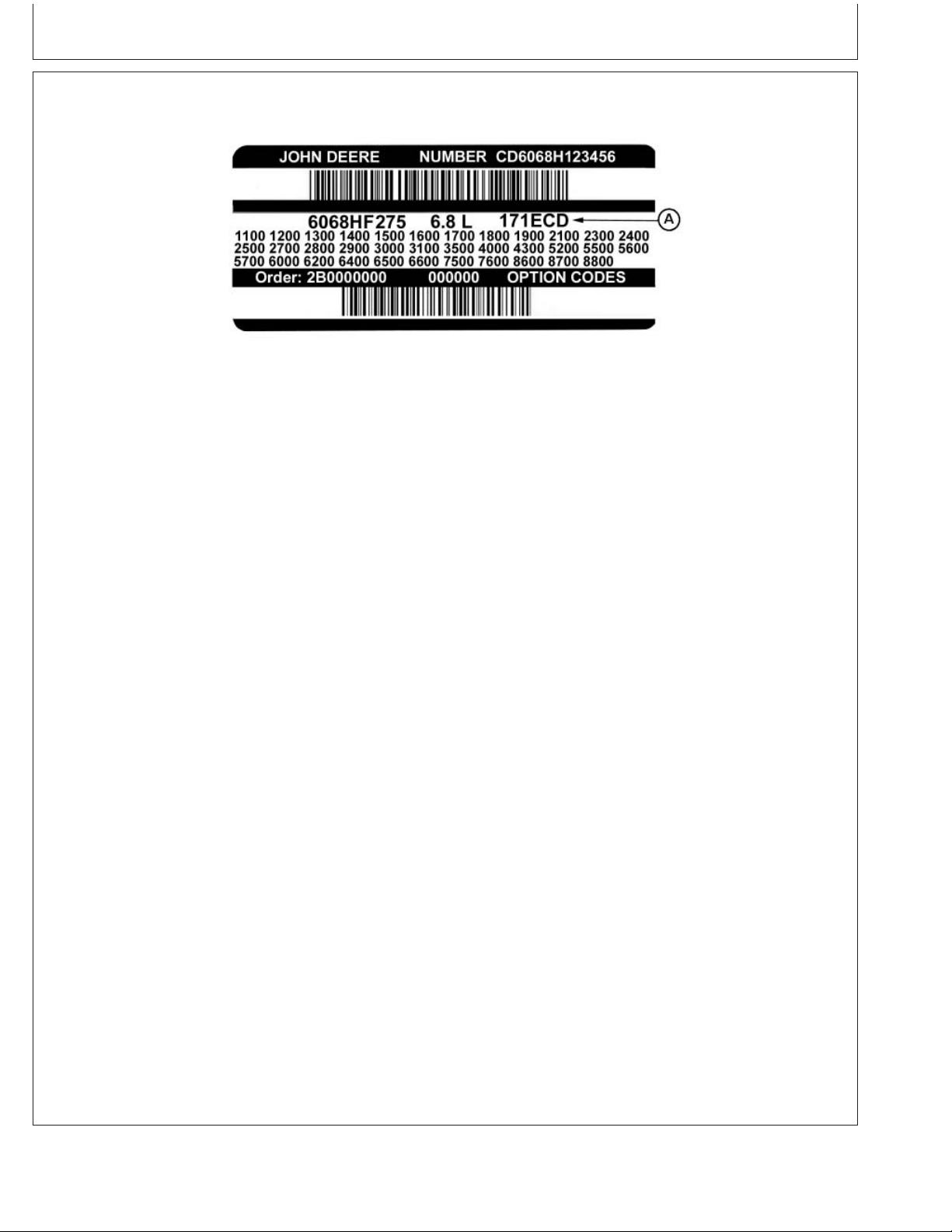
Engine Serial Number Plate
Each engine has a 13-digit John Deere engine serial
number. The first two digits identify the factory that
produced the engine:
• “CD” = Saran, France
• “PE” = Torreon, Mexico
• “T0” = Dubuque, Iowa
• “J0” = Rosario, Argentina
The engine’s serial number plate (A) is located on the
right-hand side of cylinder block behind the fuel filter.
A—Serial Number Plate
01-1
OURGP11,0000274 –19–04AUG06–1/1
RG8007 –UN–15JAN99
13-Digit Engine Serial Number Plate
RG,RG34710,5506 –19–27JUL06–1/1
080706
PN=11
Page 14

Record Keeping
Record Engine Serial Number
Record all of the numbers and letters found on your
engine serial number plate in the spaces provided below.
This information is very important for repair parts or
warranty information.
Engine Serial Number (B)
Engine Model Number (C)
Coefficient of Absorption Value (D)
(Saran Engines Only)
NOTE: Effective in April 2005, engine serial numbers
were changed at the 7th digit to show the
Emission Level. Previously this digit identified the
type of aspiration.
On earlier engines the 7th digit showed the
aspiration code as follows:
Saran Engine Serial Number Plate
RG11949 –UN–07NOV01
RG11948 –UN–06NOV01
Torreon Engine Serial Number Plate
•
“A” for turbocharged with air-to-water aftercooler
•
“D” for naturally aspirated
•
“H” for turbocharged with air-to-air aftercooler
•
“T” for turbocharged only
On later engines after April 2005, the seventh digit
will be as follows:
•
“B” for non-certified engines
•
“C” for Tier 1 / Stage I engines
•
“G” for Tier 2 / Stage II engines
•
“L” for Tier 3 / Stage IIIA engines
OURGP11,0000070 –19–27JUL06–1/1
01-2
080706
PN=12
Page 15
Record Keeping
Engine Option Codes
A—Engine Base Code
In addition to the serial number plate, OEM engines
have an engine option code label affixed to the rocker
arm cover. These codes indicate which of the engine
options were installed on your engine at the factory.
When in need of parts or service, furnish your
authorized servicing dealer or engine distributor with
these numbers.
RG11946 –UN–06NOV01
The engine option code label includes an engine base
code (A). This base code must also be recorded along
with the option codes.
The first two digits of each code identify a specific
group, such as alternators. The last two digits of each
code identify one specific option provided on your
engine, such as a 12-volt, 55-amp alternator.
NOTE: These option codes are based on the latest
information available at the time of publication.
The right is reserved to make changes at any
time without notice.
If an engine is ordered without a particular component,
the last two digits of that functional group option code
will be 99, 00, or XX. The list on the next page shows
only the first two digits of the code numbers. For future
reference such as ordering repair parts, it is important
to have these code numbers available. To ensure this
availability, enter the third and fourth digits shown on
your engine option code label in the spaces provided
on the following page.
Continued on next page
01-3
RG,RG34710,5508 –19–27JUL06–1/2
080706
PN=13
Page 16

Record Keeping
NOTE: Your engine option code label may not contain
all option codes if an option has been added
after the engine left the producing factory.
An additional option code label may also be
delivered with the engine. Place this sticker or
tag, for reference, either on this page or in the
engine owner’s warranty booklet under
If option code label is lost or destroyed,
OPTION CODES title.
consult your servicing dealer or engine
distributor selling the engine for a replacement.
Option Codes Description Option Codes Description
11 Rocker Arm Cover 50 Oil Pump
12 Oil Fill Inlet 51 Cylinder Head With Valves
13 Crankshaft Pulley/Damper 52 Auxiliary Gear Drive
14 Flywheel Housing 53 Fuel Heater
15 Flywheel 55 Shipping Stand
16 Fuel Injection Pump 56 Paint Option
17 Air Inlet 57 Coolant Pump Inlet
18 Air Cleaner 59 Oil Cooler
19 Oil Pan 60 Add-on Auxiliary Drive Pulley
20 Coolant Pump 62 Alternator Mounting Bracket
21 Thermostat Cover 63 Low Pressure Fuel Line
22 Thermostat 64 Exhaust Elbow
23 Fan Drive 65 Turbocharger
24 Fan Belt 66 Coolant Temperature Switch
25 Fan 67 Electronic Sensors (Base Engine)
26 Engine Coolant Heater 68 Crankshaft Rear Damper
27 Radiator 69 Engine Serial Number Plate
28 Exhaust Manifold 71 Engine Oil Bypass Filter
29 Crankcase Ventilator System 72 ECU Electronic Software Option
30 Starter Motor 74 Air Conditioning (Freon) Compressor
31 Alternator 75 Air Restriction Indicator
32 Instrument Panel 76 Pressure Switches and Sensors
33 Tachometer 77 Timing Gear Cover
35 Fuel Filters 78 Air Compressor
36 Front Plate 79 Engine Certification
37 Fuel Transfer Pump 81 Primary Fuel Filter And Water Separator
39 Thermostat Housing 83 Electronic Software (Vehicle Option)
40 Oil Dipstick 84 Electrical Wiring Harness
41 Belt-Driven Front Auxiliary Drive 86 Fan Pulley
43 Starting Aid 87 Belt Tensioner
44 Timing Gear Cover With Gears 88 Oil Filter
46 Cylinder Block With Liners and Camshaft 95 Special Equipment (Factory Installed)
47 Crankshaft and Bearings 96 Engine Installation Kit
48 Connecting Rods and Pistons 97 Special Equipment (Field Installed)
49 Valve Actuating Mechanism 98 Shipping (Engine Hanger Straps)
99 Service Only Items
01-4
Engine Base Code (See “A” on previous page.)
RG,RG34710,5508 –19–27JUL06–2/2
080706
PN=14
Page 17
Record Keeping
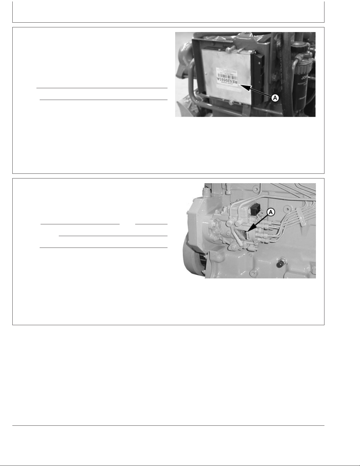
Record Engine Control Unit (ECU) Serial Number
Record the part number and serial number information
found on the serial number label (A) on the Engine
Control Unit (ECU) mounted on or near the engine.
Part No.
Serial No.
A—Serial Number Label
Record Fuel Injection Pump Model Number
Record the fuel injection pump model and serial
information found on the serial number plate (A).
Model No. RPM
Manufacturer’s No.
Serial No.
A—Serial Number Plate
Record Engine Control Unit (ECU) Serial Number
RG13799 –UN–18NOV04
OURGP12,00000AD –19–27JUL06–1/1
RG11943 –UN–06NOV01
Record Injection Pump Serial Number
01-5
RG,RG34710,5511 –19–27JUL06–1/1
080706
PN=15
Page 18
Safety
Recognize Safety Information
This is a safety-alert symbol. When you see this symbol
on your machine or in this manual, be alert to the
potential for personal injury.
Follow recommended precautions and safe operating
practices.
Understand Signal Words
A signal word—DANGER, WARNING, or CAUTION—is
used with the safety-alert symbol. DANGER identifies the
most serious hazards.
DANGER or WARNING safety signs are located near
specific hazards. General precautions are listed on
CAUTION safety signs. CAUTION also calls attention to
safety messages in this manual.
Follow Safety Instructions
Carefully read all safety messages in this manual and on
your machine safety signs. Keep safety signs in good
condition. Replace missing or damaged safety signs. Be
sure new equipment components and repair parts include
the current safety signs. Replacement safety signs are
available from your John Deere dealer.
DX,ALERT –19–29SEP98–1/1
T81389 –UN–07DEC88
TS187 –19–30SEP88
DX,SIGNAL –19–03MAR93–1/1
Learn how to operate the machine and how to use
controls properly. Do not let anyone operate without
instruction.
Keep your machine in proper working condition.
Unauthorized modifications to the machine may impair the
function and/or safety and affect machine life.
If you do not understand any part of this manual and need
assistance, contact your John Deere dealer.
05-1
TS201 –UN–23AUG88
DX,READ –19–03MAR93–1/1
080706
PN=16
Page 19
Replace Safety Signs
Replace missing or damaged safety signs. See the
machine operator’s manual for correct safety sign
placement.
Safety
Prevent Bypass Starting
Avoid possible injury or death from engine runaway.
Do not start engine by shorting across starter terminal.
Engine will start with PTO engaged if normal circuitry is
bypassed.
Start engine only from operator’s station with PTO
disengaged or in neutral.
DX,SIGNS1 –19–04JUN90–1/1
TS201 –UN–23AUG88
RG5419 –UN–28FEB89
Prevent Bypass Starting
RG,RG34710,7508 –19–27JUL06–1/1
Handle Fuel Safely—Avoid Fires
Handle fuel with care: it is highly flammable. Do not refuel
the machine while smoking or when near open flame or
sparks.
Always stop engine before refueling machine. Fill fuel tank
outdoors.
Prevent fires by keeping machine clean of accumulated
trash, grease, and debris. Always clean up spilled fuel.
05-2
TS202 –UN–23AUG88
DX,FIRE1 –19–03MAR93–1/1
080706
PN=17
Page 20
Safety
Prepare for Emergencies
Be prepared if a fire starts.
Keep a first aid kit and fire extinguisher handy.
Keep emergency numbers for doctors, ambulance service,
hospital, and fire department near your telephone.
Handle Starting Fluid Safely
Starting fluid is highly flammable.
Keep all sparks and flame away when using it. Keep
starting fluid away from batteries and cables.
To prevent accidental discharge when storing the
pressurized can, keep the cap on the container, and store
in a cool, protected location.
Do not incinerate or puncture a starting fluid container.
DX,FIRE2 –19–03MAR93–1/1
TS291 –UN–23AUG88
TS1356 –UN–18MAR92
DX,FIRE3 –19–16APR92–1/1
Handle Fluids Safely—Avoid Fires
When you work around fuel, do not smoke or work near
heaters or other fire hazards.
Store flammable fluids away from fire hazards. Do not
incinerate or puncture pressurized containers.
Make sure machine is clean of trash, grease, and debris.
Do not store oily rags; they can ignite and burn
spontaneously.
05-3
TS227 –UN–23AUG88
DX,FLAME –19–29SEP98–1/1
080706
PN=18
Page 21

Safety
Service Engines Safely
Tie long hair behind your head. Do not wear a necktie,
scarf, loose clothing, or necklace when you work near
machine tools or moving parts. If these items were to get
caught, severe injury could result.
Remove rings and other jewelry to prevent electrical
shorts and entanglement in moving parts.
Wear Protective Clothing
Wear close fitting clothing and safety equipment
appropriate to the job.
Prolonged exposure to loud noise can cause impairment
or loss of hearing.
Wear a suitable hearing protective device such as
earmuffs or earplugs to protect against objectionable or
uncomfortable loud noises.
Operating equipment safely requires the full attention of
the operator. Do not wear radio or music headphones
while operating machine.
Moving Parts
TS228 –UN–23AUG88
OURGP12,00001DA –19–27JUL06–1/1
TS206 –UN–23AUG88
Protect Against Noise
Prolonged exposure to loud noise can cause impairment
or loss of hearing.
Wear a suitable hearing protective device such as
earmuffs or earplugs to protect against objectionable or
uncomfortable loud noises.
05-4
DX,WEAR –19–10SEP90–1/1
TS207 –UN–23AUG88
DX,NOISE –19–03MAR93–1/1
080706
PN=19
Page 22

Safety
Handle Chemical Products Safely
Direct exposure to hazardous chemicals can cause
serious injury. Potentially hazardous chemicals used with
John Deere equipment include such items as lubricants,
coolants, paints, and adhesives.
A Material Safety Data Sheet (MSDS) provides specific
details on chemical products: physical and health hazards,
safety procedures, and emergency response techniques.
Check the MSDS before you start any job using a
hazardous chemical. That way you will know exactly what
the risks are and how to do the job safely. Then follow
procedures and recommended equipment.
(See your John Deere dealer for MSDS’s on chemical
products used with John Deere equipment.)
Stay Clear of Rotating Drivelines
Entanglement in rotating driveline can cause serious injury
or death.
Keep master shield and driveline shields in place at all
times. Make sure rotating shields turn freely.
TS1132 –UN–26NOV90
DX,MSDS,NA –19–03MAR93–1/1
Wear close-fitting clothing. Stop the engine and be sure
PTO driveline is stopped before making adjustments,
connections, or performing any type of service on the
engine or PTO-driven equipment.
05-5
Rotating Drivelines
TS1644 –UN–22AUG95
OUO1004,0000BD8 –19–27JUL06–1/1
080706
PN=20
Page 23
Safety
Practice Safe Maintenance
Understand service procedure before doing work. Keep
area clean and dry.
Never lubricate, service, or adjust machine while it is
moving. Keep hands, feet , and clothing from
power-driven parts. Disengage all power and operate
controls to relieve pressure. Lower equipment to the
ground. Stop the engine. Remove the key. Allow machine
to cool.
Securely support any machine elements that must be
raised for service work.
Keep all parts in good condition and properly installed. Fix
damage immediately. Replace worn or broken parts.
Remove any buildup of grease, oil, or debris.
On self-propelled equipment, disconnect battery ground
cable (-) before making adjustments on electrical systems
or welding on machine.
On towed implements, disconnect wiring harnesses from
tractor before servicing electrical system components or
welding on machine.
Work In Ventilated Area
Engine exhaust fumes can cause sickness or death. If it is
necessary to run an engine in an enclosed area, remove
the exhaust fumes from the area with an exhaust pipe
extension.
If you do not have an exhaust pipe extension, open the
doors and get outside air into the area
TS218 –UN–23AUG88
DX,SERV –19–17FEB99–1/1
TS220 –UN–23AUG88
DX,AIR –19–17FEB99–1/1
05-6
080706
PN=21
Page 24
Safety
Avoid High-Pressure Fluids
Escaping fluid under pressure can penetrate the skin
causing serious injury.
Avoid the hazard by relieving pressure before
disconnecting hydraulic or other lines. Tighten all
connections before applying pressure.
Search for leaks with a piece of cardboard. Protect hands
and body from high pressure fluids.
If an accident occurs, see a doctor immediately. Any fluid
injected into the skin must be surgically removed within a
few hours or gangrene may result. Doctors unfamiliar with
this type of injury should reference a knowledgeable
medical source. Such information is available from Deere
& Company Medical Department in Moline, Illinois, U.S.A.
X9811 –UN–23AUG88
Avoid Heating Near Pressurized Fluid Lines
Flammable spray can be generated by heating near
pressurized fluid lines, resulting in severe burns to
yourself and bystanders. Do not heat by welding,
soldering, or using a torch near pressurized fluid lines or
other flammable materials. Pressurized lines can
accidentally burst when heat goes beyond the immediate
flame area.
Do Not Open High-Pressure Fuel System
High-pressure fluid remaining in fuel lines can cause
serious injury. Do not disconnect or attempt repair of fuel
lines, sensors, or any other components between the
high-pressure fuel pump and nozzles on engines with
High Pressure Common Rail (HPCR) fuel system.
DX,FLUID –19–03MAR93–1/1
TS953 –UN–15MAY90
DX,TORCH –19–10DEC04–1/1
Only technicians familiar with this type of system can
perform repairs. (See your John Deere dealer.)
05-7
DX,WW,HPCR1 –19–07JAN03–1/1
TS1343 –UN–18MAR92
080706
PN=22
Page 25
Safety
Remove Paint Before Welding or Heating
Avoid potentially toxic fumes and dust.
Hazardous fumes can be generated when paint is heated
by welding, soldering, or using a torch.
Remove paint before heating:
• Remove paint a minimum of 100 mm (4 in.) from area
to be affected by heating. If paint cannot be removed,
wear an approved respirator before heating or welding.
• If you sand or grind paint, avoid breathing the dust.
Wear an approved respirator.
• If you use solvent or paint stripper, remove stripper with
soap and water before welding. Remove solvent or
paint stripper containers and other flammable material
from area. Allow fumes to disperse at least 15 minutes
before welding or heating.
Do not use a chlorinated solvent in areas where welding
will take place.
TS220 –UN–23AUG88
Do all work in an area that is well ventilated to carry toxic
fumes and dust away.
Dispose of paint and solvent properly.
Service Cooling System Safely
Explosive release of fluids from pressurized cooling
system can cause serious burns.
Shut off engine. Only remove filler cap when cool enough
to touch with bare hands. Slowly loosen cap to first stop
to relieve pressure before removing completely.
DX,PAINT –19–24JUL02–1/1
TS281 –UN–23AUG88
DX,RCAP –19–04JUN90–1/1
05-8
080706
PN=23
Page 26

Safety
Install Fan Guards
Rotating cooling system fans can cause serious injury.
Keep fan guards in place at all times during engine
operation. Wear close fitting clothes. Stop the engine and
be sure fan is stopped before making adjustments or
connections, or cleaning near the front of the engine.
Avoid Hot Parts
Avoid skin contact with exhaust manifolds, turbochargers
and mufflers. Keep flammable materials clear of the
turbocharger.
External dry exhaust parts become very hot during
operation. Turbochargers and exhaust manifolds may
reach temperatures as high as 600°C (1112°F) under full
load. This may ignite paper, cloth or wooden materials.
Parts on engines that have been at full load and reduced
to no load idle will maintain approximately 150°C (302°F).
Rotating Fan
TS677 –UN–21SEP89
OUOD006,000009D –19–27JUL06–1/1
TS271 –UN–23AUG88
Hot Surface
05-9
OURGP12,0000135 –19–27JUL06–1/1
080706
PN=24
Page 27
Safety
Avoid Harmful Asbestos Dust
Avoid breathing dust that may be generated when
handling components containing asbestos fibers. Inhaled
asbestos fibers may cause lung cancer.
Components in products that may contain asbestos fibers
are brake pads, brake band and lining assemblies, clutch
plates, and some gaskets. The asbestos used in these
components is usually found in a resin or sealed in some
way. Normal handling is not hazardous as long as
airborne dust containing asbestos is not generated.
Avoid creating dust. Never use compressed air for
cleaning. Avoid brushing or grinding material containing
asbestos. When servicing, wear an approved respirator. A
special vacuum cleaner is recommended to clean
asbestos. If not available, apply a mist of oil or water on
the material containing asbestos.
Keep bystanders away from the area.
TS220 –UN–23AUG88
Prevent Battery Explosions
Keep sparks, lighted matches, and open flame away from
the top of battery. Battery gas can explode.
Never check battery charge by placing a metal object
across the posts. Use a volt-meter or hydrometer.
Do not charge a frozen battery; it may explode. Warm
battery to 16°C (60°F).
Use Proper Lifting Equipment
Lifting heavy components incorrectly can cause severe
injury or machine damage.
Follow recommended procedure for removal and
installation of components in the manual.
DX,DUST –19–15MAR91–1/1
TS204 –UN–23AUG88
DX,SPARKS –19–03MAR93–1/1
05-10
DX,LIFT –19–04JUN90–1/1
TS226 –UN–23AUG88
080706
PN=25
Page 28

Safety
Use Proper Tools
Use tools appropriate to the work. Makeshift tools and
procedures can create safety hazards.
Use power tools only to loosen threaded parts and
fasteners.
For loosening and tightening hardware, use the correct
size tools. DO NOT use U.S. measurement tools on
metric fasteners. Avoid bodily injury caused by slipping
wrenches.
Use only service parts meeting John Deere specifications.
TS779 –UN–08NOV89
DX,REPAIR –19–17FEB99–1/1
05-11
080706
PN=26
Page 29

Handling Batteries Safely
CAUTION: Battery gas can explode. Keep
sparks and flames away from batteries. Use a
flashlight to check battery electrolyte level.
Never check battery charge by placing a metal
object across the posts. Use a voltmeter or
hydrometer.
Safety
Always remove grounded (—) battery clamp
first and replace it last.
CAUTION: Sulfuric acid in battery electrolyte is
poisonous. It is strong enough to burn skin, eat
holes in clothing, and cause blindness if
splashed into eyes.
Avoid the hazard by:
1. Filling batteries in a well-ventilated area.
2. Wearing eye protection and rubber gloves.
3. Avoiding breathing fumes when electrolyte is
added.
4. Avoiding spilling or dripping electrolyte.
5. Using proper jump start procedure.
If you spill acid on yourself:
1. Flush your skin with water.
2. Apply baking soda or lime to help neutralize
the acid.
3. Flush your eyes with water for 15—30
minutes. Get medical attention immediately.
Explosion
TS204 –UN–23AUG88
If acid is swallowed:
1. Do not induce vomiting.
2. Drink large amounts of water or milk, but do
not exceed2L(2qt.).
3. Get medical attention immediately.
WARNING: Battery posts, terminals, and related
accessories contain lead and lead compounds, chemicals
known to the State of California to cause cancer and
reproductive harm. Wash hands after handling.
05-12
Acid
TS203 –UN–23AUG88
DPSG,OUO1004,2758 –19–27JUL06–1/1
080706
PN=27
Page 30
Safety
Protect Against High Pressure Spray
Spray from high pressure nozzles can penetrate the skin
and cause serious injury. Keep spray from contacting
hands or body.
If an accident occurs, see a doctor immediately. Any high
pressure spray injected into the skin must be surgically
removed within a few hours or gangrene may result.
Doctors unfamiliar with this type of injury should reference
a knowledgeable medical source. Such information is
available from Deere & Company Medical Department in
Moline, Illinois, U.S.A.
Dispose of Waste Properly
TS1343 –UN–18MAR92
DX,SPRAY –19–16APR92–1/1
Improperly disposing of waste can threaten the
environment and ecology. Potentially harmful waste used
with John Deere equipment include such items as oil, fuel,
coolant, brake fluid, filters, and batteries.
Use leakproof containers when draining fluids. Do not use
food or beverage containers that may mislead someone
into drinking from them.
Do not pour waste onto the ground, down a drain, or into
any water source.
Air conditioning refrigerants escaping into the air can
damage the Earth’s atmosphere. Government regulations
may require a certified air conditioning service center to
recover and recycle used air conditioning refrigerants.
Inquire on the proper way to recycle or dispose of waste
from your local environmental or recycling center, or from
your John Deere dealer.
TS1133 –UN–26NOV90
DX,DRAIN –19–03MAR93–1/1
05-13
080706
PN=28
Page 31

Diesel Fuel
Fuels, Lubricants, and Coolant
Consult your local fuel distributor for properties of the
diesel fuel available in your area.
In general, diesel fuels are blended to satisfy the low
temperature requirements of the geographical area in
which they are marketed.
Diesel fuels specified to EN 590 or ASTM D975 are
recommended.
Required fuel properties
In all cases, the fuel shall meet the following
properties:
Cetane number of 45 minimum. Cetane number
greater than 50 is preferred, especially for
temperatures below -20°C (-4°F) or elevations above
1500 m (5000 ft).
Cold Filter Plugging Point (CFPP) below the
expected low temperature OR Cloud Point at least
5°C(9°F) below the expected low temperature.
Fuel lubricity should pass a minimum level of 3100
grams as measured by ASTM D6078 or maximum
scar diameter of 0.45 mm as measured by ASTM
D6079 or ISO 12156-1.
Sulfur content:
• Diesel fuel quality and fuel sulfur content must
comply with all existing emissions regulations for the
area in which the engine operates.
• Use of diesel fuel with sulfur content less than
0.10% (1000 ppm) is STRONGLY recommended.
• Use of diesel fuel with sulfur content 0.10% (1000
ppm to 0.50% (5000 ppm) may result in REDUCED
oil and filter change intervals.
• BEFORE using diesel fuel with sulfur content greater
than 0.50% (5000 ppm), contact your John Deere
dealer.
• DO NOT use diesel fuel with sulfur content greater
than 1.0%.
IMPORTANT: Do not mix used diesel engine oil or
any other type of lubricating oil with
diesel fuel.
IMPORTANT: Improper fuel additive usage may
cause damage on fuel injection
equipment of diesel engines.
Lubricity of Diesel Fuel
Most diesel fuels manufactured in the United States,
Canada, and the European Union have adequate
lubricity to ensure proper operation and durability of
fuel injection system components. However, diesel
fuels manufactured in some areas of the world may
lack the necessary lubricity.
IMPORTANT: Make sure the diesel fuel used in
your machine demonstrates good
lubricity characteristics.
DX,FUEL1 –19–17NOV05–1/1
Fuel lubricity should pass a minimum load level of
3100 grams as measured by ASTM D6078 or a
maximum scar diameter of 0.45 mm as measured by
ASTM D6079 or ISO 12156-1.
If fuel of low or unknown lubricity is used, add John
Deere PREMIUM DIESEL FUEL CONDITIONER (or
equivalent) at the specified concentration.
DX,FUEL5 –19–27OCT05–1/1
10-1
080706
PN=29
Page 32

Handling and Storing Diesel Fuel
Fuels, Lubricants, and Coolant
CAUTION: Handle fuel carefully. Do not fill
the fuel tank when engine is running.
DO NOT smoke while you fill the fuel tank or
service the fuel system.
Fill the fuel tank at the end of each day’s operation to
prevent water condensation and freezing during cold
weather.
Keep all storage tanks as full as practicable to
minimize condensation.
Ensure that all fuel tank caps and covers are installed
properly to prevent moisture from entering.
Monitor water content of the fuel regularly.
When using bio-diesel fuel, the fuel filter may require
more frequent replacement due to premature plugging.
Check engine oil level daily prior to starting engine. A
rising oil level may indicate fuel dilution of the engine
oil.
IMPORTANT: The fuel tank is vented through the
filler cap. If a new filler cap is
required, always replace it with an
original vented cap.
When fuel is stored for an extended period or if there
is a slow turnover of fuel, add a fuel conditioner to
stabilize the fuel and prevent water condensation.
Contact your fuel supplier for recommendations.
DX,FUEL4 –19–19DEC03–1/1
Testing Diesel Fuel
DIESELSCAN is a John Deere fuel analysis program
that can be used to monitor the quality of your fuel. The
DIESELSCAN analysis verifies fuel type, cleanliness,
water content, suitability for cold weather operation, and
whether the fuel meets specifications.
Check with your John Deere dealer for availability of
DIESELSCAN kits.
DIESELSCAN is a trademark of Deere & Company
DX,FUEL6 –19–14NOV05–1/1
10-2
080706
PN=30
Page 33

Bio-Diesel Fuel
Fuels, Lubricants, and Coolant
Consult your local fuel distributor for properties of the
bio-diesel fuel available in your area.
Bio-diesel fuels may be used ONLY if the bio-diesel
fuel properties meet the latest edition of ASTM D6751,
EN 14214, or equivalent specification.
It is recommended to purchase bio-diesel fuel blended
with B100 from a BQ-9000 Accredited Producer or a
BQ-9000 Certified Marketer as recommended by the
National Bio-diesel Board.
The maximum allowable bio-diesel concentration is a
5% blend (also known as B5) in petroleum diesel fuel.
It has been found that bio-diesel fuels may improve
lubricity in concentrations up to this 5% blend.
When using a blend of bio-diesel fuel, the engine oil
level must be checked daily when the air temperature
is –10°C (14°F) or lower. If oil becomes diluted with
fuel, shorten oil change intervals accordingly.
IMPORTANT: Raw pressed vegetable oils are NOT
acceptable for use as fuel in any
concentration in John Deere
engines.
leaving deposits on injectors and in
the combustion chamber.
A major environmental benefit of bio-diesel fuel is its
ability to biodegrade. This makes proper storage and
handling of bio-diesel fuel especially important. Areas
of concern include:
• Quality of new fuel
• Water content of the fuel
• Problems due to aging of the fuel
Potential problems resulting from deficiencies in the
above areas when using bio-diesel fuel in
concentrations above 5% may lead to the following
symptoms:
• Power loss and deterioration of performance
• Fuel leakage
• Corrosion of fuel injection equipment
• Coked and/or blocked injector nozzles, resulting in
engine misfire
• Filter plugging
• Lacquering and/or seizure of internal components
• Sludge and sediments
• Reduced service life of engine components
These oils do not burn completely,
and will cause engine failure by
Consult your fuel supplier for additives to improve
storage and performance of bio-diesel fuels.
DX,FUEL7 –19–14NOV05–1/1
10-3
080706
PN=31
Page 34

Fuels, Lubricants, and Coolant
Minimizing the Effect of Cold Weather on Diesel Engines
John Deere diesel engines are designed to operate
effectively in cold weather.
However, for effective starting and cold weather
operation, a little extra care is necessary. The
information below outlines steps that can minimize the
effect that cold weather may have on starting and
operation of your engine. See your John Deere dealer
for additional information and local availability of cold
weather aids
Use Winter Grade Fuel
When temperatures fall below 5°C (40°F), winter grade
fuel (Grade No. 1-D fuel in North America) is best
suited for cold weather operation. Winter grade fuel
has a lower cloud point and a lower pour point.
Cloud point is the temperature at which wax will begin
to form in the fuel and this wax causes fuel filters to
plug. Pour point is the temperature at which fuel
begins to thicken and becomes more resistant to flow
through fuel pumps and lines.
NOTE: On an average, winter grade fuel has a lower
BTU (heat content) rating. Using winter grade
fuel may reduce power and fuel efficiency, but
should not cause any other engine
performance effects. Check the grade of fuel
being used before troubleshooting for low
power complaints in cold weather operation.
CAUTION: Do not use any starting fluid with
an engine equipped with glow plugs
Coolant Heater
An engine block heater (coolant heater) is an available
option to aid cold weather starting.
Seasonal Viscosity Oil and Proper Coolant
Concentration
Use seasonal grade viscosity engine oil based ion the
expected air temperature range between oil changes
and proper concentration of low silicate antifreeze as
recommended. (See DIESEL ENGINE OIL and
ENGINE COOLANT requirements this section.)
Diesel Fuel Flow Additive
Use John Deere Premium Diesel Fuel Conditioner
(Winter) or equivalent to treat fuel during the cold
weather season. This winter formulation is a
combination diesel fuel conditioner and anti-gel
additive.
IMPORTANT: Treat fuel when outside temperature
drops below 0°C (32°F). For best
results, use with untreated fuel.
Follow all recommended instructions
on label.
Air Intake Heater
An air intake heater is an available option to aid cold
weather starting.
CAUTION: Do not use any starting fluid with
an air intake heater.
Starting Fluid
A starting fluid port on the intake is available to aid
cold weather starting.
Winterfronts
Use of fabric, cardboard , or solid winterfronts is not
recommended with any John Deere engine. Their use
can result in excessive engine coolant, oil, and charge
air temperatures. This can lead to reduced engine life,
loss of power and poor fuel economy. Winterfronts
may also put abnormal stress on fan and fan drive
components potentially causing premature failures.
Continued on next page
DX,FUEL10 –19–16DEC05–1/2
10-4
080706
PN=32
Page 35

Fuels, Lubricants, and Coolant
If winterfronts are used, they should never totally close
off the grill frontal area. Approximately 25% area in the
center of the grill should remain open at all times. At
no time should the air blockage device be applied
directly to the radiator core.
Radiator Shutters
If equipped with a thermostatically controlled radiator
shutter system, this system should be regulated in
such a way that the shutters are completely open by
Diesel Engine Break-In Oil
New engines are filled at the factory with John Deere
ENGINE BREAK-IN OIL. During the break-in period,
add John Deere ENGINE BREAK-IN OIL as needed to
maintain the specified oil level.
Change the oil and filter after the first 100 hours of
operation of a new or rebuilt engine.
After engine overhaul, fill the engine with John Deere
ENGINE BREAK-IN OIL.
the time the coolant reaches 93°C (200°F) to prevent
excessive intake manifold temperatures. Manually
controlled systems are not recommended.
If air-to-air aftercooling is used, the shutters must be
completely open by the time the intake manifold air
temperature reaches the maximum allowable
temperature out of the charge air cooler.
For more information, see your John Deere dealer.
DX,FUEL10 –19–16DEC05–2/2
• ACEA Oil Sequence E1
After the break-in period, use John Deere PLUS-50
or other diesel engine oil as recommended in this
manual.
IMPORTANT: Do not use PLUS-50 oil or engine
oils meeting any of the following
during the first 100 hours of
operation of a new or rebuilt engine:
If John Deere ENGINE BREAK-IN OIL is not available,
use a diesel engine oil meeting one of the following
during the first 100 hours of operation:
• API Service Classification CE
• API Service Classification CD
• API Service Classification CC
• ACEA Oil Sequence E2
PLUS-50 is a trademark of Deere & Company.
10-5
API CI-4 PLUS API CF
API CI-4 ACEA E7
API CH-4 ACEA E6
API CG-4 ACEA E5
API CF-4 ACEA E4
API CF-2 ACEA E3
These oils will not allow the engine
to break-in properly.
DX,ENOIL4 –19–19DEC05–1/1
080706
PN=33
Page 36
Fuels, Lubricants, and Coolant
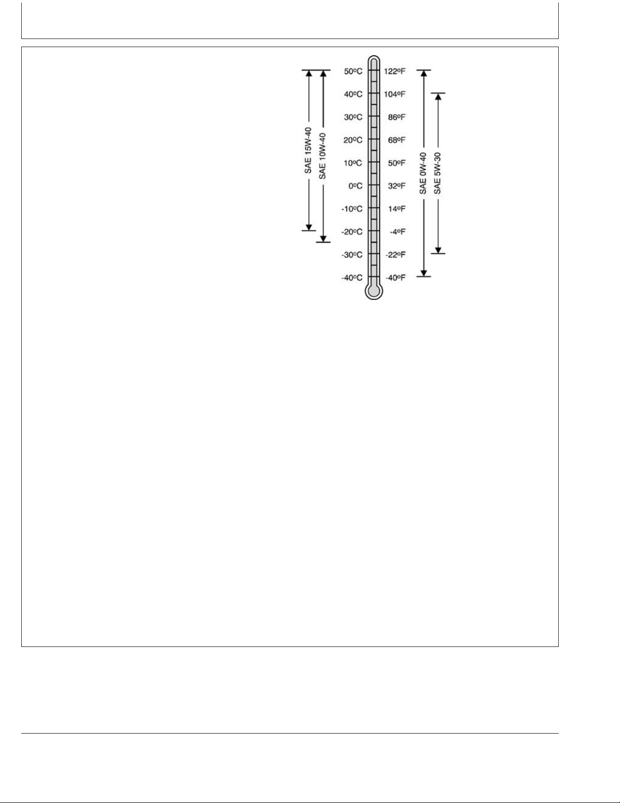
Diesel Engine Oil
Use oil viscosity base on the expected air temperature
range during the period between oil changes.
John Deere PLUS-50 oil is preferred.
Oil meeting one of the following specifications are also
recommended:
• ACEA Oil Sequence E7
• ACEA Oil Sequence E6
• ACEA Oil Sequence E5
• ACEA Oil Sequence E4
Extended service intervals may apply when John Deere
PLUS-50, ACEA E7, ACEA E6, ACEA E5, or ACEA E4
engine oils are used. Consult your John Deere dealer for
more information.
Other oils may be used if they meet one or more of the
following:
TS1675 –UN–31OCT03
• John Deere TORQ-GARD SUPREME
• API Service Category CI-4 PLUS
• API Service Category CI-4
• API Service Category CH-4
• ACEA Oil Sequence E3
Multi-viscosity diesel engine oils are preferred.
Diesel fuel quality and fuel sulfur content must comply
with all existing emissions regulations for the area in
which the engine operates.
DO NOT use diesel fuel with sulfur content greater than
1.0% (10 000 ppm).
PLUS-50 is a trademark of Deere & Company
TORQ-GARD SUPREME is a trademark of Deere & Company
DX,ENOIL7 –19–23NOV05–1/1
10-6
080706
PN=34
Page 37

Fuels, Lubricants, and Coolant
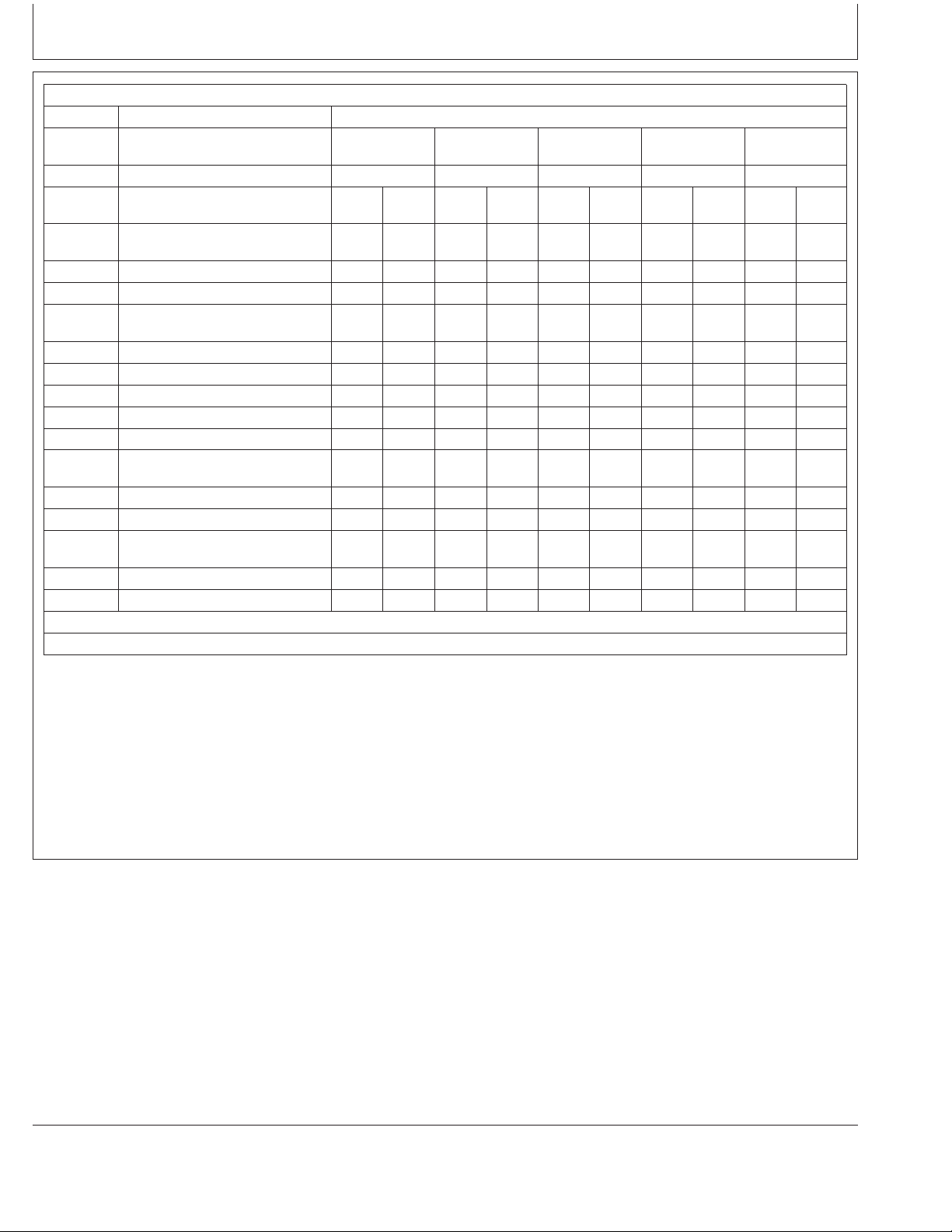
Diesel Engine Oil and Filter Service Intervals
The oil and filter service intervals in the following
charts should be used as guidelines. Actual service
intervals depend on operation and maintenance
practices. Use oil analysis to determine the actual
useful life of the oil and to aid in selection of the
proper oil and filter service interval.
Oil and filter service intervals are based on a
combination of oil pan capacity, type of engine oil and
filter used, and sulfur content of the diesel fuel.
Diesel fuel sulfur level will affect engine oil and filter
service intervals. Higher fuel sulfur levels reduce oil
and filter service intervals as shown in the table:
• Use of diesel fuel with sulfur content less than
0.05% (500 ppm ) is strongly recommended.
• Use of diesel fuel with sulfur content 0.05% (500
ppm) to 0.50% (5000 ppm) may result in REDUCED
oil and filter change intervals as shown in the table.
• BEFORE using diesel fuel with sulfur content greater
than 0.50% (5000 ppm), contact your John Deere
dealer.
Oil types (premium or standard) in the tables include:
Refer to the charts on the following pages to find the
proper oil and filter service interval for your engine.
Using Charts to Find Oil and Filter Service Interval
1. Determine your engine model and power rating and
find it in the left column of 4.5 L or 6.8 L chart.
2. Locate your engine oil pan option code (19__) on
engine label.
3. In the chart column under your oil pan code, select
whether you use premium oil (PLUS-50 or
equivalent) or standard grade oil.
4. Determine the sulfur content of your diesel fuel.
5. Now you can find the proper oil and filter change
interval by lining up your power level and fuel sulfur
content with oil pan/oil type column. The number
indicates how frequent your oil and filter should be
changed (example: every 500 hours of operation).
• “Premium Oils” include John Deere PLUS-50,
ACEA E7, ACEA E6, ACEA E5 or ACEA E4 oils.
• “Standard Oils” include John Deere TORQ-GARD
SUPREME, API CI-4 PLUS, API CI-4, , API CH4
or ACEA E3 oils.
NOTE: The 500 hour extended oil and filter change
interval is allowed only if
ALL
the following
conditions are met:
• Engine equipped with an oil pan that allows capacity
for this extended drain interval.
• Use of premium oil John Deere PLUS-50, ACEA E7,
ACEA E6, ACEA E5 or ACEA E4
• Use of an approved John Deere oil filter
• Use of diesel fuel with sulfur content less than
0.05% (500 ppm)
PLUS-50 is a trademark of Deere & Company
TORQ-GARD SUPREME is a trademark of Deere & Company
Continued on next page
10-7
OURGP11,0000012 –19–27JUL06–1/3
080706
PN=35
Page 38
Fuels, Lubricants, and Coolant
4.5 L Engine Oil and Filter Service Intervals in Hours of Operation
Oil Pan Option Codes
Power Fuel Sulfur Content
Rating
kW (hp) Std Prem Std Oil Prem Std Prem Std Oil Prem Std Oil Prem
36-50 Less Than 0.05% (500 ppm) 250 500 250 500 250 500 250 500 250 500
(48-67)
0.05% - 0.50% (500 - 5000 ppm) 150 400 150 400 150 400 150 400 150 400
0.50% - 1.0% (5000 - 10,000 ppm) 125 250 125 250 125 250 125 250 125 250
63-86 Less Than 0.05% (500 ppm) 250 375 250 500 250 500 250 500 250 500
(84-115)
0.05% - 0.50% (500 - 5000 ppm) 150 275 150 400 150 400 150 400 150 400
0.50% - 1.0% (5000 - 10,000 ppm) 125 175 125 250 125 250 125 250 125 250
93 (125) Less Than 0.05% (500 ppm) 250 375 250 375 250 500 250 500 250 500
0.05% - 0.50% (500 - 5000 ppm) 150 275 150 275 150 400 150 400 150 400
0.50% - 1.0% (5000 - 10,000 ppm) 125 175 125 175 125 250 125 250 125 250
99-108 Less Than 0.05% (500 ppm) 250 375 250 375 250 375 250 500 250 500
(133-145)
0.05% - 0.50% (500 - 5000 ppm) 150 275 150 275 150 275 150 400 150 400
0.50% - 1.0% (5000 - 10,000 ppm) 125 175 125 175 125 175 125 250 125 250
117-143 Less Than 0.05% (500 ppm) 250 375 250 375 250 375 250 375 250 500
(157-192)
0.05% - 0.50% (500 - 5000 ppm) 150 275 150 275 150 275 150 275 150 400
0.50% - 1.0% (5000 - 10,000 ppm) 125 175 125 175 125 175 125 175 125 250
Use of premium oil also requires use of an approved John Deere oil filter.
a
If considering fuel with sulfur content over 0.50% (5000 ppm), contact your John Deere Dealer (dealer to reference DTAC solution).
a
1901, 1902 1903 1904 1923 1976
Interval Interval Interval Interval Interval
Oil Oil Oil Oil Oil Oil Oil
Continued on next page
10-8
OURGP11,0000012 –19–27JUL06–2/3
080706
PN=36
Page 39

Fuels, Lubricants, and Coolant
6.8 L Engine Oil and Filter Service Intervals in Hours of Operation
Oil Pan Option Codes
Power Fuel Sulfur Content
Rating 1909, 1944
kW (hp) Std Prem Std Prem Std Prem Std Prem Std Prem
101-129 Less Than 0.05% (500 ppm) 250 500 250 500 250 500 250 500 250 500
(135-173)
0.05% - 0.50% (500 - 5000 ppm) 150 400 150 400 150 400 150 400 150 400
0.50% - 1.0% (5000 - 10,000 ppm) 125 250 125 250 125 250 125 250 125 250
138 (185) Less Than 0.05% (500 ppm) 250 375 250 500 250 500 250 500 250 500
0.05% - 0.50% (500 - 5000 ppm) 150 275 150 400 150 400 150 400 150 400
0.50% - 1.0% (5000 - 10,000 ppm) 125 175 125 250 125 250 125 250 125 250
149-175 Less Than 0.05% (500 ppm) 250 375 250 375 250 500 250 500 250 500
(200-235)
0.05% - 0.50% (500 - 5000 ppm) 150 275 150 275 150 400 150 400 150 400
0.50% - 1.0% (5000 - 10,000 ppm) 125 175 125 175 125 250 125 250 125 250
187 (250) Less Than 0.05% (500 ppm) 250 375 250 375 250 375 250 500 250 500
0.05% - 0.50% (500 - 5000 ppm) 150 275 150 275 150 275 150 400 150 400
0.50% - 1.0% (5000 - 10,000 ppm) 125 175 125 175 125 175 125 250 125 250
205-210 Less Than 0.05% (500 ppm) 250 375 250 375 250 375 250 375 250 500
(275-272)
0.05% - 0.50% (500 - 5000 ppm) 150 275 150 275 150 275 150 275 150 400
0.50% - 1.0% (5000 - 10,000 ppm) 125 175 125 175 125 175 125 175 125 250
234 (314) Less Than 0.05% (500 ppm) 250 375 250 375 250 375 250 375 250 375
0.05% - 0.50% (500 - 5000 ppm) 150 275 150 275 150 275 150 275 150 275
0.50% - 1.0% (5000 - 10,000 ppm) 125 175 125 175 125 175 125 175 125 175
Use of premium oil also requires use of an approved John Deere oil filter.
a
If considering fuel with sulfur content over 0.50% (5000 ppm), contact your John Deere Dealer (dealer to reference DTAC solution).
a
1956 1907, 1908, 1924 19AC 1961
Interval Interval Interval Interval Interval
Oil Oil Oil Oil Oil Oil Oil Oil Oil Oil
Mixing of Lubricants
In general, avoid mixing different brands or types of oil.
Oil manufacturers blend additives in their oils to meet
certain specifications and performance requirements.
Mixing different oils can interfere with the proper
functioning of these additives and degrade lubricant
performance.
OURGP11,0000012 –19–27JUL06–3/3
Consult your John Deere dealer to obtain specific
information and recommendations.
DX,LUBMIX –19–18MAR96–1/1
10-9
080706
PN=37
Page 40
Fuels, Lubricants, and Coolant
Oil Filters
Filtration of oils is critical to proper operation and
lubrication.
Always change filters regularly as specified in this manual.
Use filters meeting John Deere performance
specifications.
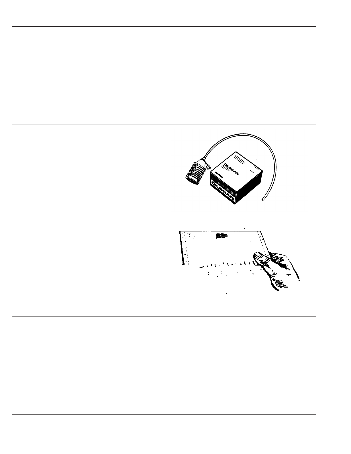
OILSCANand COOLSCAN
OILSCANand COOLSCAN are John Deere sampling
programs to help you monitor machine performance and
identify potential problems before they cause serious
damage.
Oil and coolant samples should be taken from each
system prior to its recommended change interval.
DX,FILT –19–18MAR96–1/1
Check with your John Deere dealer for the availability of
OILSCAN and COOLSCAN kits.
OILSCAN is a registered trademark of Deere & Company.
COOLSCAN is a trademark of Deere & Company.
T6828AB –UN–15JUN89T6829AB –UN–18OCT88
DX,OILSCAN –19–02DEC02–1/1
10-10
080706
PN=38
Page 41

Fuels, Lubricants, and Coolant
Alternative and Synthetic Lubricants
Conditions in certain geographical areas may require
lubricant recommendations different from those printed in
this manual.
Some John Deere brand coolants and lubricants may not
be available in your location.
Consult your John Deere dealer to obtain information and
recommendations.
Synthetic lubricants may be used if they meet the
performance requirements as shown in this manual.
The temperature limits and service intervals shown in this
manual apply to both conventional and synthetic oils.
Re-refined base stock products may be used if the
finished lubricant meets the performance requirements.
Lubricant Storage
Your equipment can operate at top efficiency only
when clean lubricants are used.
Use clean containers to handle all lubricants.
Whenever possible, store lubricants and containers in
an area protected from dust, moisture, and other
contamination. Store containers on their side to avoid
water and dirt accumulation.
DX,ALTER –19–15JUN00–1/1
Make certain that all containers are properly marked to
identify their contents.
Properly dispose of all old containers and any residual
lubricant they may contain.
DX,LUBST –19–18MAR96–1/1
10-11
080706
PN=39
Page 42

Fuels, Lubricants, and Coolant
Grease
Use grease based on NLGI consistency numbers and the
expected air temperature range during the service interval.
John Deere SD POLYUREA GREASE is preferred.
The following greases are also recommended
• John Deere HD LITHIUM COMPLEX GREASE
• John Deere HD WATER RESISTANT GREASE
• John Deere GREASE-GARD
Other greases may be used if they meet the following:
NLGI Performance Classification GC-LB
IMPORTANT: Some types of grease thickeners are
not compatible with others. Consult
your grease supplier before mixing
different types of grease
TS1673 –UN–31OCT03
GREASE-GARD is a trademark of Deere & Company
DX,GREA1 –19–07NOV03–1/1
10-12
080706
PN=40
Page 43

Diesel Engine Coolant
Fuels, Lubricants, and Coolant
The engine cooling system is filled to provide
year-round protection against corrosion and cylinder
liner pitting, and winter freeze protection to -37°C
(-34°F). If protection at lower temperatures is required,
consult your John Deere dealer for recommendations.
John Deere COOL-GARD Prediluted Coolant is
preferred for service.
John Deere COOL-GARD Prediluted Coolant is
available in a concentration of either 50% ethylene
glycol or 55% propylene glycol.
Additional recommended coolants
The following engine coolant is also recommended:
• John Deere COOL-GARD Coolant Concentrate in a
40% to 60% mixture of concentrate with quality
water.
John Deere COOL-GARD coolants do not require use
of supplemental coolant additives, except for periodic
replenishment of additives during the drain interval.
Other fully formulated coolants
Other fully formulated low silicate ethylene or
propylene glycol base coolants for heavy-duty engines
may be used if they meet one of the following
specifications:
Other low silicate ethylene glycol base coolants for
heavy-duty engines may also be used if they meet one
of the following specifications:
• ASTM D4985 ethylene glycol base prediluted (50%)
coolant
• ASTM D4985 ethylene glycol base coolant
concentrate in a 40% to 60% mixture of concentrate
with quality water
Coolants meeting ASTM D4985 require an initial
charge of supplemental coolant additives, formulated
for protection of heavy duty diesel engines against
corrosion and cylinder liner erosion and pitting. They
also require periodic replenishment of additives during
the drain interval.
Other coolants
It is possible that neither John Deere COOL-GARD nor
coolants meeting one of the coolant standards listed
above is available in the geographical area where
service is performed. If these coolants are unavailable,
use a coolant concentrate or prediluted coolant with a
quality additive package that provides cylinder liner
cavitation protection and protects the cooling system
metals (cast iron, aluminum alloys, and copper alloys
such as brass) from corrosion.
The additive package must be part of one of the
following coolant mixtures:
• ASTM D6210 prediluted (50%) coolant
• ASTM D6210 coolant concentrate in a 40% to 60%
mixture of concentrate with quality water
Coolants meeting ASTM D6210 do not require use of
supplemental coolant additives, except for periodic
replenishment of additives during the drain interval.
Coolants requiring supplemental coolant additives
COOL-GARD is a trademark of Deere & Company
• ethylene glycol or propylene glycol base prediluted
(40% to 60%) coolant
• ethylene glycol or propylene glycol base coolant
concentrate in a 40% to 60% mixture of concentrate
with quality water
Water quality
Continued on next page
DX,COOL3 –19–27OCT05–1/2
10-13
080706
PN=41
Page 44

Fuels, Lubricants, and Coolant
Water quality is important to the performance of the
cooling system. Distilled, deionized, or demineralized
water is recommended for mixing with ethylene glycol
and propylene glycol base engine coolant concentrate.
IMPORTANT: Do not use cooling system sealing
additives or antifreeze that contains
sealing additives.
Drain Intervals for Diesel Engine Coolant
Drain the factory fill engine coolant, flush the cooling
system, and refill with new coolant after the first 3 years
or 3000 hours of operation.
Subsequent drain intervals are determined by the coolant
used for service. At each interval, drain the coolant, flush
the cooling system, and refill with new coolant.
IMPORTANT: Do not mix ethylene glycol and
propylene glycol base coolants.
DX,COOL3 –19–27OCT05–2/2
When John Deere COOL-GARD is used, the drain
interval may be extended to 5 years or 5000 hours of
operation, provided that the coolant is tested annually
AND additives are replenished, as needed, by adding a
supplemental coolant additive.
If John Deere COOL-GARD is used but the coolant is not
tested OR additives are not replenished by adding a
supplemental coolant additive, the drain interval is 3 years
or 3000 hours of operation
If COOL-GARD is not used, the drain interval is reduced
to 2 years or 2000 hours of operation.
COOL-GARD is a trademark of Deere & Company
DX,COOL11 –19–19DEC03–1/1
10-14
080706
PN=42
Page 45

Supplemental Coolant Additives
Fuels, Lubricants, and Coolant
The concentration of coolant additives is gradually
depleted during engine operation. For all
recommended coolants, replenish additives between
drain intervals by adding a supplemental coolant
additive every 12 months or as determined necessary
by coolant testing.
John Deere COOLANT CONDITIONER is
recommended as a supplemental coolant additive in
John Deere engines.
IMPORTANT: Do not add a supplemental coolant
additive when the cooling system is
drained and refilled with John
DeereCOOL-GARD.
COOL-GARD is a trademark of Deere & Company
If other coolants are used, consult the coolant supplier
and follow the manufacturer’s recommendation for use
of supplemental coolant additives.
The use of non-recommended supplemental coolant
additives may result in additive drop-out and gelation
of the coolant.
Add the manufacturer’s recommended concentration of
supplemental coolant additive. DO NOT add more than
the recommended amount.
DX,COOL4 –19–07NOV03–1/1
Testing Diesel Engine Coolant
Testing Diesel Engine Coolant
Maintaining adequate concentrations of glycol and
inhibiting additives in the coolant is critical to protect
the engine and cooling system against freezing,
corrosion, and cylinder liner erosion and pitting.
Test the coolant solution at intervals of 12 months or
less and whenever excessive coolant is lost through
leaks or overheating.
Coolant test strips
Coolant test strips are available from your John Deere
dealer. These test strips provide a simple, effective
method to check the freeze point and additive levels of
your engine coolant.
Compare the results to the supplemental coolant
additive (SCA) chart to determine the amount of
inhibiting additives in your coolant and whether more
John Deere COOLANT CONDITIONER should be
added.
COOLSCAN and COOLSCAN PLUS
For a more thorough evaluation of your coolant,
perform a COOLSCAN or COOLSCAN PLUS analysis,
where available. See your John Deere dealer for
information.
COOLSCAN is a trademark of Deere & Company
COOLSCAN PLUS is a trademark of Deere & Company
10-15
DX,COOL9 –19–19DEC03–1/1
080706
PN=43
Page 46

Fuels, Lubricants, and Coolant
Operating in Warm Temperature Climates
John Deere engines are designed to operate using glycol
base engine coolants.
Always use a recommended glycol base engine coolant,
even when operating in geographical areas where freeze
protection is not required.
IMPORTANT: Water may be used as coolant
in
emergency situations only.
Foaming, hot surface aluminum and
iron corrosion, scaling, and cavitation
will occur when water is used as the
coolant, even when coolant
conditioners are added.
Drain cooling system and refill with
recommended glycol base engine
coolant as soon as possible.
Disposing of Coolant
Improperly disposing of engine coolant can threaten the
environment and ecology.
DX,COOL6 –19–18MAR96–1/1
Use leakproof containers when draining fluids. Do not use
food or beverage containers that may mislead someone
into drinking from them.
Do not pour waste onto the ground, down a drain, or into
any water source.
Inquire on the proper way to recycle or dispose of waste
from your local environmental or recycling center, or from
your John Deere engine distributor or servicing dealer.
10-16
TS1133 –UN–26NOV90
RG,RG34710,7543 –19–27JUL06–1/1
080706
PN=44
Page 47

Instrument Panel Identification
Instrument Panels - Identification
The instrument panels shown compare the panel offered
for mechanically controlled “270” series engines (shown at
right) and electronically controlled earlier engines and
electronically controlled later engines (shown on next
page). The electronically controlled earlier instrument
panel operation is covered in Section 16. The
electronically controlled later instrument panels
(Full-Featured and Basic versions) are covered in Section
17. The mechanically controlled “270” series engines are
covered in Section 18.
Instrument Panel For Earlier Mechanically Controlled “270” Engines
RG13343 –UN–24NOV03
(See Section 18)
Deluxe Instrument Panel For Later Mechanically Controlled “270”
Continued on next page
15-1
RG13359 –UN–06FEB04
Engines (See Section 18)
OURGP11,0000071 –19–27JUL06–1/2
080706
PN=45
Page 48
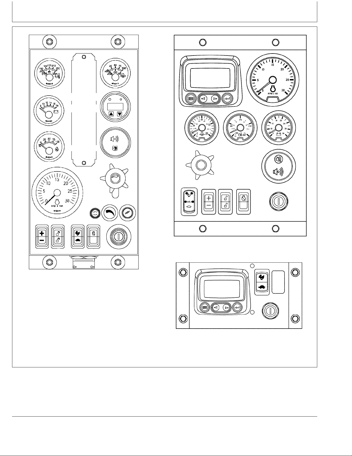
Instrument Panel Identification
Instrument Panel For Earlier Electronically Controlled Engines (See
Section 16)
Full-Featured Instrument Panel For Later Electronically Controlled
RG13274 –UN–28OCT03
Engines (See Section 17)
RG13273 –UN–20NOV03
RG13275 –UN–21OCT03
Basic Instrument Panel For Later Electronically Controlled Engines
(See Section 17)
OURGP11,0000071 –19–27JUL06–2/2
15-2
080706
PN=46
Page 49

Instrument Panel - Elect. Cont. Earlier Engines
Instrument Panel
This instrument panel for earlier P
OWERTECH
4.5 L and
6.8 L electronically controlled engines is electronically
linked to the John Deere engine control unit (ECU). This
allows the operator to monitor engine performance as well
as to diagnose any troubles during engine operation.
All electronic engine controls are optional equipment for
John Deere P
OWERTECH
OEM Engines. These electronic
controls may be provided by the equipment manufacturer
instead of purchased from John Deere. Refer to your
engine application manual for specific guidelines if John
Deere sourced controls and instrumentation are not used.
A—Engine Oil Pressure Gauge
B—Amber “WARNING” Indicator
C—Red “STOP ENGINE” Indicator
D—Diagnostic Gauge/Hour Meter
E—Touch Switch
F—Touch Switch
G—Audible Alarm (Optional)
H—Audible Alarm Override Switch (Optional)
I—Analog Throttle Control (Optional)
J—Dimmer Control (Optional)
K—Engine Preheater Indicator (Optional)
L—Key Start Switch
M—Override Shutdown Rocker Switch
N—High-Low Speed Select Rocker Switch
O—Bump Speed Enable Rocker Switch
P—Speed Select Rocker Switch
Q—Fuse Holder (5-Amp Fuse)
R—Tachometer
S—Power Meter (Percent Load) (Optional)
T—Voltmeter (Optional)
U—Engine Coolant Temperature Gauge
P
OWERTECH
is a trademark of Deere & Company.
Instrument Panel (Earlier Electronically Controlled Engines)
Continued on next page
16-1
RG11169 –UN–01NOV00
OURGP11,000027A –19–07AUG06–1/7
080706
PN=47
Page 50

Instrument Panel - Elect. Cont. Earlier Engines
IMPORTANT: Any time an electric gauge or meter
does not register correctly, replace with
a new one. Do not attempt to repair it.
All gauges are plug-in type.
Following is a brief description of the electronic controls
found on John Deere-provided instrument panels. Refer to
manufacturer’s literature for information on controls not
provided by Deere.
Engine Oil Pressure Gauge
The engine oil pressure gauge (A) indicates engine oil
pressure in pounds per square inch (psi) or kPa. An
optional audible alarm (G) warns the operator if engine oil
pressure falls below a safe operating pressure.
Amber “Warning” Indicator
The amber “WARNING” indicator (B) signals an abnormal
condition such as low oil pressure, high coolant
temperature, water in fuel, low battery voltage, etc.
Observe displayed code in window of diagnostic
gauge/hour meter (D) for diagnostic trouble code (DTC).
(Use the service code menu. See USING DIAGNOSTIC
GAUGE TO ACCESS ENGINE INFORMATION later in
this section.)
Red “Stop Engine” Indicator
The Red “STOP ENGINE” indicator (C) signals operator to
stop engine immediately or as soon as safely possible. A
condition exists that could cause damage to engine.
Diagnostic Gauge/Hour Meter
The diagnostic gauge/hour meter (D) displays diagnostic
trouble codes (DTCs) as they are accessed. Other
information on the engine can be accessed using the
touch switches (E and F). The hour meter shows the
operating hours of the engine. If engine trouble occurs,
the gauge will alternately flash from displayed parameter
to the message “SvrcCode”. Then the touch switches (E
and F) can be used to access the trouble code (see
following).
Instrument Panel
RG11169 –UN–01NOV00
Continued on next page
16-2
OURGP11,000027A –19–07AUG06–2/7
080706
PN=48
Page 51
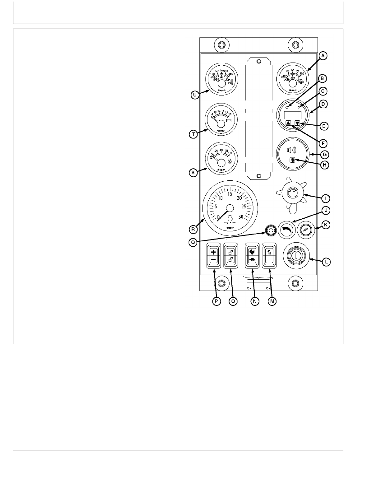
Instrument Panel - Elect. Cont. Earlier Engines
Touch Switches
The touch switches are used to change the display on the
window of the diagnostic gauge to access engine
performance data. Pressing the DOWN switch (E) or UP
switch (F) scrolls through various engine parameters and
diagnostic trouble codes. (See Using Diagnostic Gauge
To Access Engine Information on the following pages for
instructions.)
Audible Alarm (Optional)
The audible alarm (G) sounds whenever a low oil
pressure, high coolant temperature or
water-in-fuel/plugged fuel filter condition exists. This
includes all signals that light up the amber “WARNING”
indicator (B) or the red “STOP ENGINE” indicator (C).
Audible Alarm Override Switch (Optional)
The audible alarm override switch (H) can be pressed to
silence the alarm for approximately 2-1/2 minutes.
Analog Throttle Control (Optional)
The throttle control (I) is used to control engine speed.
This control is available only on engines with analog
throttle.
Dimmer Control (Optional)
The dimmer control (J) is used to control illumination of
the instrument panel gauges.
Instrument Panel For Earlier Engines
Continued on next page
RG11169 –UN–01NOV00
OURGP11,000027A –19–07AUG06–3/7
16-3
080706
PN=49
Page 52
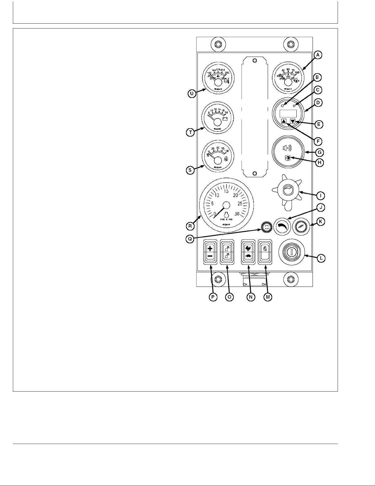
Instrument Panel - Elect. Cont. Earlier Engines
Engine Preheater Indicator (Optional)
The engine preheater indicator (K) lights up while the
engine is being preheated for cold weather starting. When
the engine is warmed up, the light goes off, indicating the
engine can now be started.
Key Start Switch
The three-position key start switch (L) controls the engine
electrical system. When the key switch is turned clockwise
to “START”, the engine will crank. When the engine starts,
the key is released and returns to the “ON” (RUN)
position.
Override Shutdown Rocker Switch
Switch will be present, but may not be active, depending
on engine controller (ECU) options originally selected. If
switch is active, pressing the upper half of the override
shutdown switch (M) will override an engine shutdown
signal. The switch must be pressed within 30 seconds to
prevent undesired shutdown of engine. Pressing this
switch will override the engine shutdown for 30 seconds at
a time to move vehicle to a safe location.
High-Low Speed Select Rocker Switch
This instrument panel has two versions, one with a two
position switch as shown, and one with a three position
switch. The two position switch has high/low and is used
to set the engine operating speeds at slow (turtle) or fast
(rabbit). Factory preset idle speeds can also be adjusted
using bump speed enable switch (O) with speed select
switch (P).
The three position switch has Slow (turtle), Middle (Adj)
and Fast (rabbit) settings. Slow (turtle) position is factory
preset at low engine idle, while middle (ADJ) position is
factory set at high engine idle. To adjust engine speeds,
See Changing Engine Speeds in Section 18.
Instrument Panel For Earlier Engines
Continued on next page
RG11169 –UN–01NOV00
OURGP11,000027A –19–07AUG06–4/7
16-4
080706
PN=50
Page 53

Instrument Panel - Elect. Cont. Earlier Engines
Bump Speed Enable Rocker Switch
This is a three-position switch (O) with the center position
as “OFF” (locked). With this switch in the “OFF” position,
the speed select switch (P) is also locked, to prevent
accidental changes in operating speed. Pressing upper or
lower half of switch (O) will unlock or enable the bump
speed switch to take effect using speed select switch (P).
Speed Select Rocker Switch
The speed select switch (P) is used to bump engine
speed up (+) or down (-) in small increments during
operation. This switch must be used with the bump speed
enable switch (O) in the unlocked position (top or bottom
half of button depressed).
How To Select Preset Operating Speeds (Bump
Speeds)
First select slow or fast speed option by pressing high-low
speed select switch (N) to “turtle” (slow) or “rabbit” (fast).
Then you can press either the upper or lower portion of
the bump speed enable switch (O) to unlock the high or
low setting. The bump speed enable must be held down
as the speed select switch (P) is used to change the high
or low setting by pressing (+) to increase speed or (-) to
decrease speed.
Once the slow idle speed has been set, the bump speed
enable switch must be pressed and released three
times within two seconds to commit the new
operating speed to memory. If not done, the engine’s
new speed will only be effective until the key switch is
shut off. Then the speed will revert back to the previous
setting.
The fast idle speed cannot be locked into memory. It will
always go back to the factory preset fast idle speed.
Fuse Holder
The fuse holder (Q) contains a 5-amp fuse for power to
the instrument panel.
Instrument Panel For Earlier Engines
RG11169 –UN–01NOV00
Continued on next page
16-5
OURGP11,000027A –19–07AUG06–5/7
080706
PN=51
Page 54

Instrument Panel - Elect. Cont. Earlier Engines
Tachometer
The tachometer (R) indicates engine speed in hundreds of
revolutions per minute (rpm).
Percent Load (Optional)
The power meter (S) shows percent of available power
being used by the engine.
Voltmeter
The voltmeter (T) indicates system battery voltage. The
amber “WARNING” light (B) will illuminate when battery
voltage is too low for proper operation of the fuel injection
system.
Engine Coolant Temperature Gauge
The coolant temperature gauge (U) indicates engine
coolant temperature in degrees Celsius or Fahrenheit. An
optional audible alarm (G) warns the operator if coolant
temperature rises above the preset safe operating
temperature.
Cruise Control
Engine ECUs are available with the cruise control
function. The cruise control is an off-road type that
maintains a constant engine rpm under varying load
conditions.
The cruise cancel/resume function is a one-button cancel,
then resume, function. The first time contact is made with
the cruise control active, the cruise control will disengage
and the engine speed will drop to idle. If the contact is
made again within one minute and with the engine speed
above 1300 rpm, the cruise control will “resume”. This
feature allows the placement of the cancel/resume button
in a convenient location in the vehicle cab and does not
require the use of the normal cruise controls for
momentary interruptions in cruise operation.
Instrument Panel For Earlier Engines
RG11169 –UN–01NOV00
Continued on next page
16-6
OURGP11,000027A –19–07AUG06–6/7
080706
PN=52
Page 55

Instrument Panel - Elect. Cont. Earlier Engines
The cancel/resume function is intended for applications
like agricultural tractors and sprayers that turn around at
the end of each row in a field. This allows the operator to
use the throttle and/or brake to turn the vehicle around.
When ready to resume field operations, the operator
brings the engine speed above 1300 rpm and activates
the cancel/resume function again to resume cruise speed.
An internal timer gives the operator one minute to
complete the turnaround maneuver.
The cruise control has the normal functions of:
• Cruise control power “ON” or “OFF”.
• “Set” or “bump up” engine speed.
• “Resume” or “bump down” engine speed.
• Use vehicle brake or clutch pedal to disengage cruise
control.
The “bump up” and “bump down” speed controls allow the
operator to change the set speed. Small engine speed
changes can be made by “bumping” the control switch.
Holding the “bump up” or “bump down” switch will result in
greater engine rpm changes until the engine reaches
either full speed or idle. The cruise control cannot operate
beyond the normal min/max engine speeds.
16-7
OURGP11,000027A –19–07AUG06–7/7
080706
PN=53
Page 56
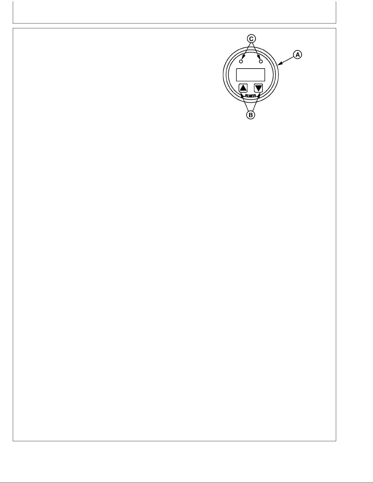
Instrument Panel - Elect. Cont. Earlier Engines
Using Diagnostic Gauge to Access Engine Information
The diagnostic gauge (A) allows the operator to view
many readouts of engine functions and diagnostic trouble
codes (DTCs). The gauge is linked to the electronic
control system and its sensors. This allows the operator to
monitor engine functions and to troubleshoot the engine
systems when needed.
Press the two touch switches (B) to view the various
engine functions in sequence. The displays can be
selected as either customary English or metric units.
NOTE: Engine parameters which can be accessed will
vary with the engine application.
The following menu of engine parameters can be
displayed on the diagnostic gauge window:
• Accelerator pedal position
• Percentage load @ current speed
• Actual engine percent torque
• Engine speed
• Trip distance
• Total vehicle distance
• Engine hours
• Trip fuel
• Total fuel used
• Coolant temperature
• Fuel temperature
• Engine oil temperature
• Engine intercooler temperature
• Fuel delivery pressure
• Engine oil level
• Engine oil pressure
• Coolant pressure
• Coolant level
• Wheel base vehicle speed
• Fuel rate
• Barometric pressure
• Air inlet temperature
• Boost pressure
• Intake manifold temperature
• Air filter differential pressure
• Exhaust gas temperature
Diagnostic Gauge (Earlier Engines)
RG10031 –UN–28OCT99
A—Diagnostic Gauge
B—Touch Switches
C—Lights
Continued on next page
16-8
OURGP11,0000072 –19–27JUL06–1/2
080706
PN=54
Page 57

Instrument Panel - Elect. Cont. Earlier Engines
• Electrical potential (voltage)
• Battery potential (voltage), switched
• Transmission oil pressure
• Transmission oil temperature
• Injector metering rail #1 pressure
• Injector metering rail #2 pressure
• Estimated percent fan speed
• Active service (diagnostic) codes
• Stored service (diagnostic) codes
The diagnostic gauge includes a two-line by
eight-character backlit Liquid Crystal Display (LCD). The
top line displays the data label, i.e. “EngHrs” and the
bottom line displays the matching unit information, i.e.
“1246 hrs.”. The diagnostic gauge uses two touch
switches (UP and DOWN) for scrolling through the engine
parameter list and viewing the menu list. Two lights (C)
(amber and red) are used to signal active trouble
messages received by the diagnostic gauge.
OURGP11,0000072 –19–27JUL06–2/2
16-9
080706
PN=55
Page 58

Instrument Panel - Elect. Cont. Earlier Engines
Using Touch Switches to Display Information
Using Touch Switches
Continued on next page
16-10
RG9947 –19–09DEC99
DPSG,OUOD007,2841 –19–27JUL06–1/2
080706
PN=56
Page 59

Instrument Panel - Elect. Cont. Earlier Engines
The touch switches on the diagnostic gauge allow
quick and easy navigation through the menu to find the
information needed.
The diagram on the preceding page is a typical Main
Menu of Engine Parameters. The Main Menu has 14
entries; the first 10 are engine data parameters, and
the last four are sub-menu entry points.
Accessing the Menus
The following two rules are used for accessing the
various items on the menus:
1. To scroll through the parameter list, press
either
the UP or DOWN touch switch.
2. To select or exit a sub-menu,
simultaneously
press the UP and DOWN switches.
Selecting Engine Data Parameters
To read any of the engine parameters, press either UP
or DOWN switch (as shown on diagram) until the top
line of the display shows the desired information.
Selecting Sub-Menus
Press either the UP or DOWN switch until the top line
of the display shows the label of the desired
sub-menu. Then press BOTH the UP and DOWN
switches at the same time. This action will select the
sub-menu and the next screen on the display will list
the sub-menu items. This is also the way to access
diagnostic trouble codes (DTCs).
DPSG,OUOD007,2841 –19–27JUL06–2/2
16-11
080706
PN=57
Page 60

Instrument Panel - Elect. Cont. Earlier Engines
Changing Units of Measure (English or Metric)
Changing Units Of Measure
The diagnostic gauge can display engine data in either
English or Metric units. To toggle between these, the
Units Sub-Menu
To select the
, must be selected.
Units Sub-Menu
, press the UP or DOWN
switch until the top line of the display reads “Units”.
Then press BOTH the UP and DOWN switches at the
same time to select the
Units Sub-Menu
. The above
diagram shows the steps for selecting the desired units
of measure. Two options are available:
1. Press both the switches to retain the current units
designation.
2. Press either UP or DOWN switch to toggle the units
selection, then press both switches to select the
desired unit of measure.
DPSG,OUOD007,2842 –19–27JUL06–1/1
16-12
RG10018 –19–28OCT99
080706
PN=58
Page 61

Instrument Panel - Elect. Cont. Earlier Engines
16-13
080706
PN=59
Page 62

Instrument Panel - Elect. Cont. Earlier Engines
Viewing Engine Configuration Data
Viewing Engine Configuration Data
Continued on next page
16-14
RG10019 –19–28OCT99
DPSG,OUOD007,2842 –19–27JUL06–1/2
080706
PN=60
Page 63

Instrument Panel - Elect. Cont. Earlier Engines
The diagnostic gauge can display the engine
configuration data stored in the engine control unit
(ECU). To select the
Engine Configuration Sub-Menu
(see diagram on previous page), press the UP or
DOWN switch until the top line of the display reads
“E-Config”. Then press BOTH the UP and DOWN
switches at the same time to select the
Configuration Sub-Menu
. The diagnostic gauge will
Engine
display the engine configuration data as shown in the
diagram.
DPSG,OUOD007,2842 –19–27JUL06–2/2
16-15
080706
PN=61
Page 64
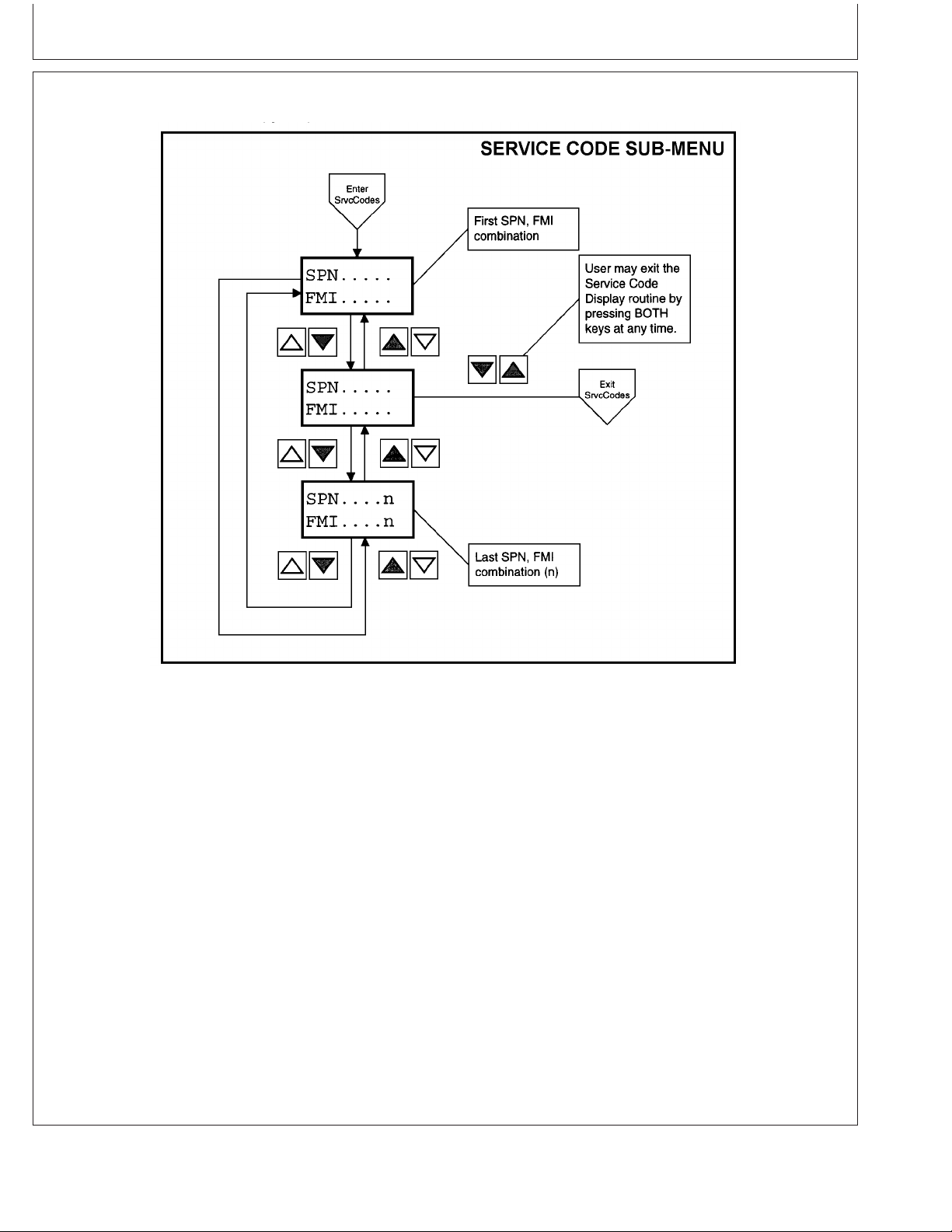
Instrument Panel - Elect. Cont. Earlier Engines
Viewing Active Engine Service Codes/Diagnostic Trouble Codes (DTCs)
Viewing Active Service Codes/Diagnostic Trouble Codes (DTCs)
The diagnostic gauge continuously monitors all
messages broadcast over the Control Area Network
(CAN) and displays all active service codes /diagnostic
trouble codes (DTCs) at the time the message is
broadcast. The word “SrvcCode” is displayed on the
second line. The display will cycle every 5 seconds
between the currently displayed parameter and the
“SrvcCode” message until the active service code
(DTC) clears. To view the active codes, select the
Service Code Sub-Menu
by pressing the UP or DOWN
switch until the top line of the display reads
“SrvcCode”. Then press BOTH the UP and DOWN
switches at the same time to select the Service Code
RG11170 –UN–02NOV00
(DTC) Sub-Menu. The diagnostic gauge has the ability
to display all active service codes (DTCs) received.
The diagram above titled
Sub-Menu
shows the process for selecting active
Service Code (DTC)
service codes (DTCs) and their values.
NOTE: For a list of Service Codes or Diagnostic
Trouble Codes (DTCs) and their causes, refer
to TROUBLESHOOTING Section 45, later in
this manual. An alternate method of accessing
trouble codes for engines for engines without
the diagnostic gauge is the blink code method.
See Section 45.
16-16
DPSG,OUOD002,1928 –19–27JUL06–1/1
080706
PN=62
Page 65
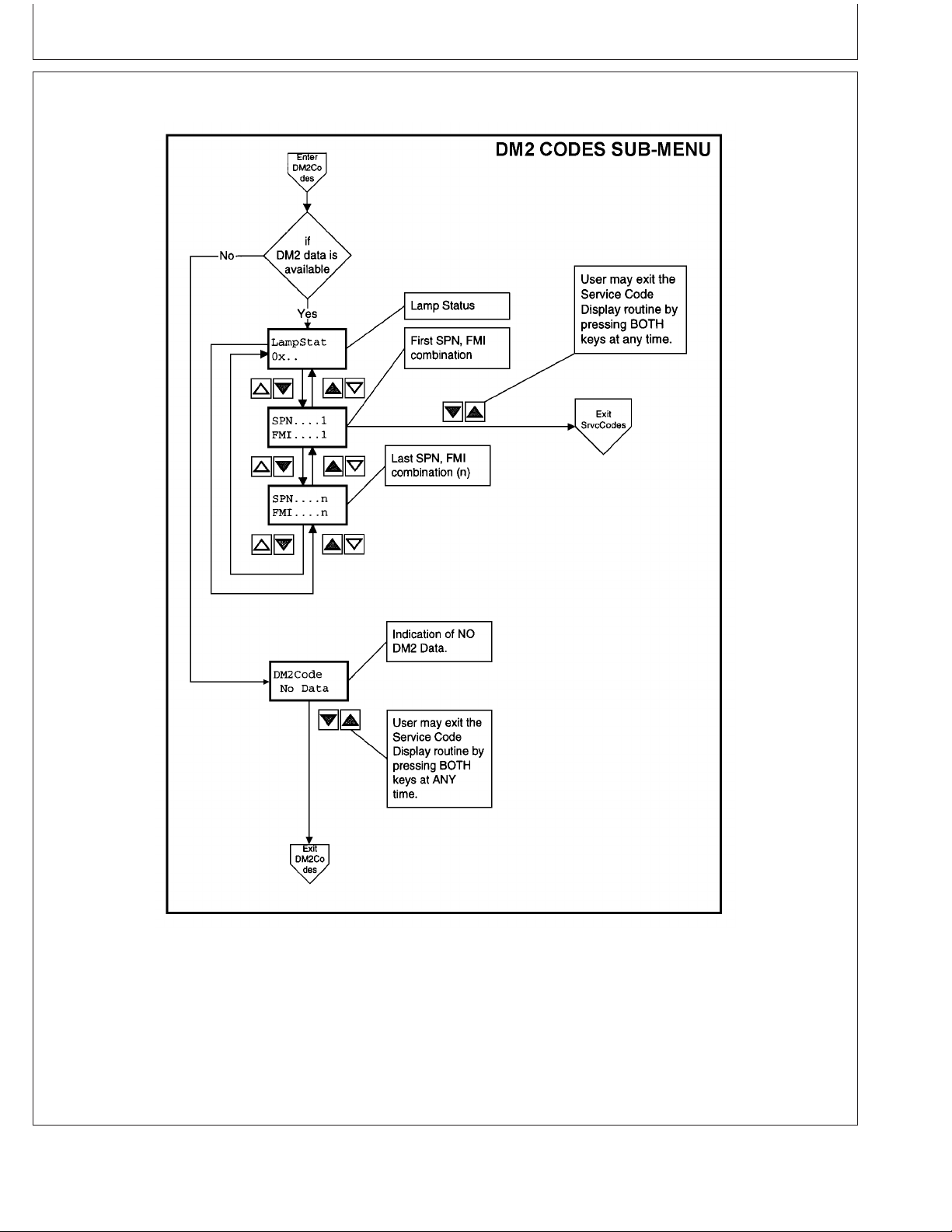
Instrument Panel - Elect. Cont. Earlier Engines
Viewing Stored Service Codes/Diagnostic Trouble Codes (DTCs) in the Engine ECU
Viewing Stored Service Codes/Diagnostic Trouble Codes (DTCs)
The diagnostic gauge can request stored service
codes (DTCs) from the engine. The stored service
codes may be used for diagnostic and service needs.
To view the stored service codes, it is necessary to
select the
DM2 Codes Sub-Menu
by pressing the UP
or DOWN switch until the top line of the display reads
“DM2 Codes”. Then press BOTH the UP and DOWN
switches at the same time to select the
Sub-Menu.
The gauge will display the stored service
codes according to the menus shown in the diagram.
OUOD006,000006B –19–27JUL06–1/1
16-17
RG10021 –19–28OCT99
DM2 Codes
080706
PN=63
Page 66
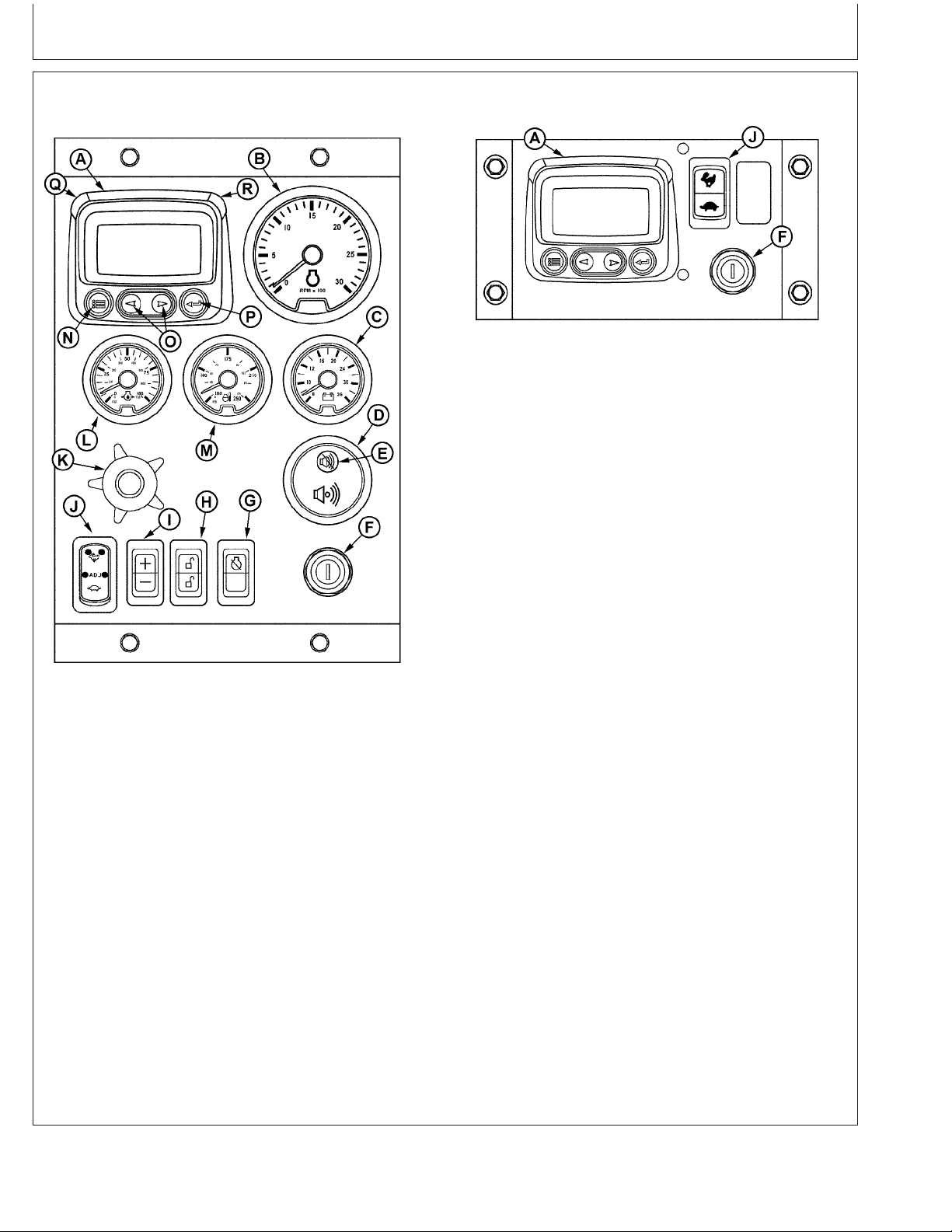
Instrument Panel - Elect. Cont. Later Engines
Instrument Panels
Basic Instrument Panel
RG13276 –UN–28OCT03
Full-Featured Instrument Panel
A—Diagnostic Gauge/Hour F—Key Switch K—Analog Throttle Control O—Arrow Keys
Meter G—Override Shutdown Rocker (Optional) P—Enter Key
B—Tachometer Switch L—Oil Pressure Gauge Q—Amber “WARNING”
C—Voltmeter (Optional) H—Bump Enable Rocker M—Coolant Temperature Indicator Light
D—Audible Alarm (Optional) Switch Gauge R—Red “STOP ENGINE”
E—Audible Alarm Override I—Speed Select Rocker Switch N—Menu Key Indicator Light
Button J—High-Low Speed Select
Rocker Switch
RG13277 –UN–22OCT03
Later Tier 2 John Deere P
OWERTECH
OEM Engines
have an electronic control system, which has the
following controls and gauges as shown. The following
information applies only to those controls and gauges
supplied by John Deere. Refer to your engine
application manual for specific guidelines if John
Deere-sourced controls and instrumentation are not
used.
P
OWERTECH
is a trademark of Deere & Company.
Following is a brief description of the available optional
electronic controls and gauges found on John Deere
provided instrument panels. Refer to manufacturer’s
literature for information on controls not provided by
Deere.
Continued on next page
OURGP11,0000073 –19–04AUG06–1/3
17-1
080706
PN=64
Page 67

Instrument Panel - Elect. Cont. Later Engines
Instrument Panel (Continued)
A—Diagnostic Gauge/Hour Meter
The diagnostic gauge (A) displays diagnostic trouble
codes (DTCs) as they are accessed. Other information
on the engine can be accessed using the touch keys
(N, O and P). The hour meter feature shows the
operating hours of the engine and should be used as a
guide for scheduling periodic maintenance. If the
diagnostic gauge receives a trouble code from an
engine control unit, the current display will switch to a
warning or shutdown (depending on the severity of the
code) screen that will display the trouble code number,
the description of the code and the corrective action
needed.
B—Tachometer
The tachometer (B) indicates engine speed in
hundreds of revolutions per minute (rpm).
C—Voltmeter (Optional)
The voltmeter (C) indicates system battery voltage.
The amber “Warning” light (Q) will illuminate when
battery voltage is too low for proper operation of the
fuel injection system.
D—Audible Alarm (Optional)
The audible alarm (D) will sound whenever low oil
pressure, high coolant temperature, or water-in-fuel
conditions exist. This includes all signals that light up
the amber “warning” indicator (intermittent alarm) or
the red “stop engine” indicator (steady alarm).
E—Audible Alarm Override Button
The optional audible alarm has an override button (E)
that silences the audible alarm for approximately two
minutes when pressed.
F—Key Start Switch
The three-position key start switch (F) controls the
engine electrical system. When the key switch is
turned clockwise to “START”, the engine will crank.
When the engine starts, the key is released and
returns to the “ON” (RUN) position.
G—Override Shutdown Rocker Switch
Switch will be present, but may not be active,
depending on engine controller (ECU) options
originally selected. If switch is active, pressing the
upper half of the override shutdown switch (G) will
override an engine shutdown signal. The switch must
be pressed within 30 seconds to prevent undesired
shutdown of engine. Pressing this switch will override
the engine shutdown for 30 seconds at a time to move
vehicle to a safe location.
H—Bump Speed Enable Rocker Switch
This is a three-position switch (H) with the center
position as “OFF” (locked). With this switch in the
“OFF” position, the speed select switch (I) is also
locked, to prevent accidental changes in operating
speed. Pressing upper or lower half of switch (H) will
unlock or enable the bump speed switch to take effect
using speed select switch (I).
I—Speed Select Rocker Switch
The speed select switch (I) is used to bump engine
speed up (+) or down (-) in small increments during
operation. This switch must be used with the bump
speed enable switch (H) in the unlocked position (top
or bottom half of button depressed).
J—High-Low Speed Select Rocker Switch
The high-low speed select switch (J) is used to set the
engine operating speeds at slow (turtle) or fast (rabbit).
Factory preset idle speeds can also be adjusted using
bump speed enable switch (H) with speed select
switch (I).
The basic instrument panel will have the high-low
speed select switch only. Press and hold up (+) or
down (-) to adjust engine speed as desired. The
engine speed selected will not be held in the memory.
To adjust engine speeds, See Changing Engine
Speeds in Section 18.
Continued on next page
17-2
OURGP11,0000073 –19–04AUG06–2/3
080706
PN=65
Page 68

Instrument Panel - Elect. Cont. Later Engines
How To Select Preset Operating Speeds (Bump
Speeds)
First select Turtle (Slow) or Adj by pressing speed
select switch (J) to “Turtle” (slow) or “Adj”(center).
Then you can press either the upper or lower portion
of the bump speed enable switch (H) to unlock the
setting. The bump speed enable must be held down as
the speed select switch (J) is used to change the
setting by pressing (+) to increase speed or (-) to
decrease speed.
Once the slow idle speed has been set, the bump
speed enable switch must be pressed and released
three times within two seconds to commit the new
operating speed to memory. If not done, the engine’s
new speed will only be effective until the key switch is
shut off. Then the speed will revert back to the
previous setting.
The fast idle speed is not adjustable. It will always go
back to the factory preset fast idle speed.
K—Analog Throttle Control (Optional)
warns the operator if coolant temperature rises above
the preset safe operating temperature.
N—Menu Key
The menu key is pressed to either enter or exit the
menu screens on the diagnostic gauge.
O—Arrow Keys
Use the arrow keys (O) to change the display on the
window of the diagnostic gauge and to access engine
performance data.
Pressing the left arrow to scroll to the left or upward or
the right arrow to scroll to the right or downward. This
will allow you to view various engine parameters and
any diagnostic trouble codes that occur.
Refer to the following story for accessing engine
information on the diagnostic gauge using the touch
keys.
P—Enter Key
The throttle control (K) is used to control engine
speed. This control is available only on engines with
analog throttle.
L—Engine Oil Pressure Gauge
The oil pressure gauge (L) indicates engine oil
pressure. An audible alarm (D) warns the operator if
engine oil pressure falls below a safe operating
pressure.
M—Engine Coolant Temperature Gauge
The engine coolant temperature gauge (M) indicates
engine coolant temperature. An audible alarm (D)
The enter key is pressed to select the parameter that
is highlighted on the screen.
Q—Amber “WARNING” Indicator Light
When light comes on, an abnormal condition exists. It
is not necessary to shutdown engine immediately, but
problem should be corrected as soon as possible.
R—Red “STOP ENGINE” Indicator Light
When light comes on, stop engine immediately or as
soon as safely possible to prevent engine damage.
Correct problem before restarting.
OURGP11,0000073 –19–04AUG06–3/3
17-3
080706
PN=66
Page 69
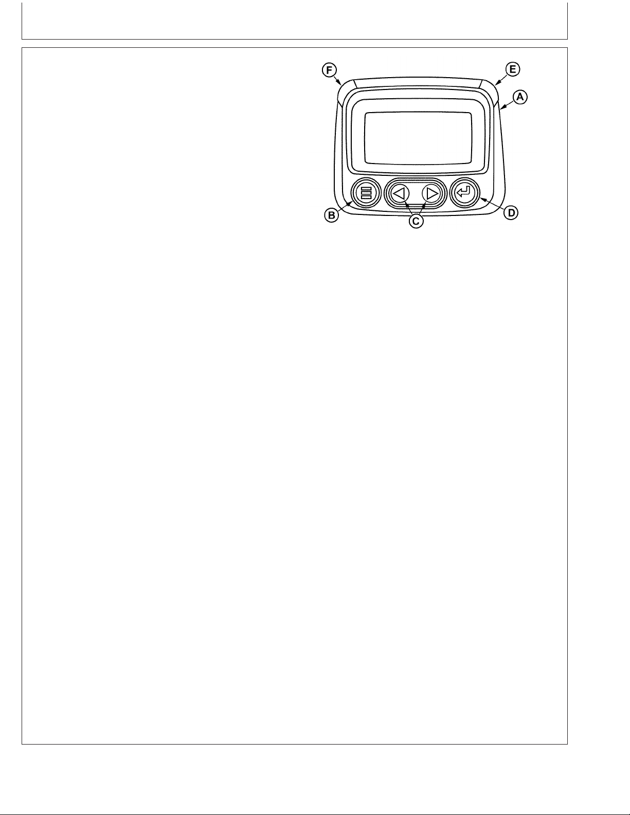
Instrument Panel - Elect. Cont. Later Engines
Using Diagnostic Gauge to Access Engine Information
The diagnostic gauge (A) allows the operator to view
many readouts of engine functions and trouble codes
(DTCs). The gauge is linked to the electronic control
system and its sensors. This allows the operator to
monitor engine functions and to troubleshoot the engine
systems when needed.
Press the menu key (B) to access the various engine
functions in sequence. The displays can be selected as
either customary English or metric units. The following
menu of engine parameters can be displayed on the
diagnostic gauge window:
Diagnostic Gauge (Later Engines)
RG13132 –UN–09SEP03
• Engine hours
• Engine rpm
• System voltage
• Percent engine load at the current rpm
• Coolant temperature
• Oil pressure
• Throttle position
• Intake manifold temperature
• Current fuel consumption
• Active service (diagnostic) codes
• Stored service (diagnostic) codes from the engine
• Set the units for display
• View the engine configuration parameters
NOTE: Engine parameters which can be accessed will
vary with the engine application. Six languages for
readouts are available and can be selected during
setup of gauge.
The diagnostic gauge includes a graphical backlit Liquid
Crystal Display (LCD) screen. The display can show either
a single parameter or a quadrant display showing four
parameters simultaneously. The diagnostic gauge uses
two arrow keys (C) for scrolling through the engine
parameter list and viewing the menu list and an enter key
(D) for selecting highlighted items. The red (E) and amber
(F) lights are used to signal active trouble code received
by the diagnostic gauge.
A—Diagnostic Gauge
B—Menu Key
C—Arrow Keys
D—Enter Key
E—Red “STOP ENGINE” Indicator Light
F—Amber “WARNING” Indicator Light
17-4
OURGP11,0000074 –19–27JUL06–1/1
080706
PN=67
Page 70
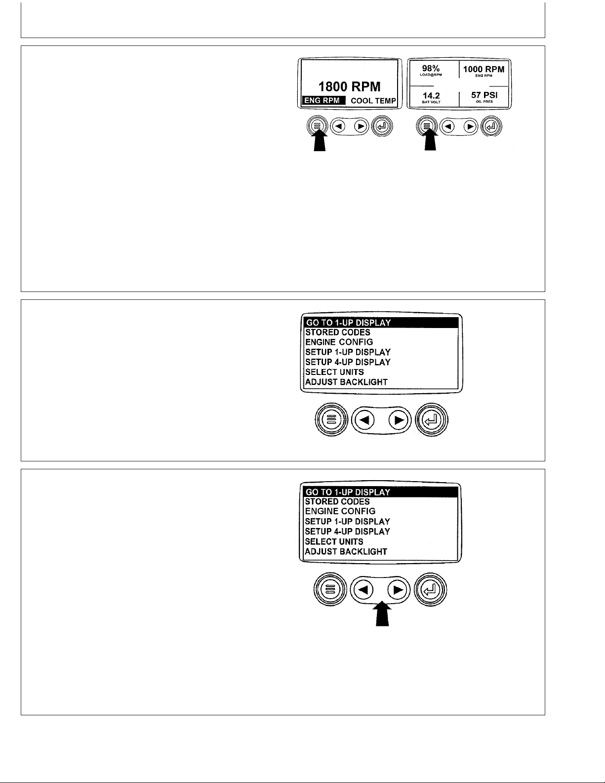
Instrument Panel - Elect. Cont. Later Engines
Main Menu Navigation
NOTE: The engine does not need to be running to
navigate the diagnostic gauge screens. If engine
start up is desired, See Starting The Engine. All of
the engine values illustrated on the diagnostic
gauge indicate the engine is running.
1. Turn the key switch to the ON position. Starting at the
single or four engine parameter display, press the
"Menu" key.
Menu Key
RG13159 –UN–26SEP03
OURGP11,00000A9 –19–27JUL06–1/5
2. The first seven items of the "Main Menu" will be
displayed.
3. Pressing the "Arrow" keys will scroll through the menu
selections.
Menu Display
RG13160 –UN–02OCT03
OURGP11,00000A9 –19–27JUL06–2/5
Continued on next page
17-5
Main Menu Items
RG13161 –UN–02OCT03
OURGP11,00000A9 –19–27JUL06–3/5
080706
PN=68
Page 71
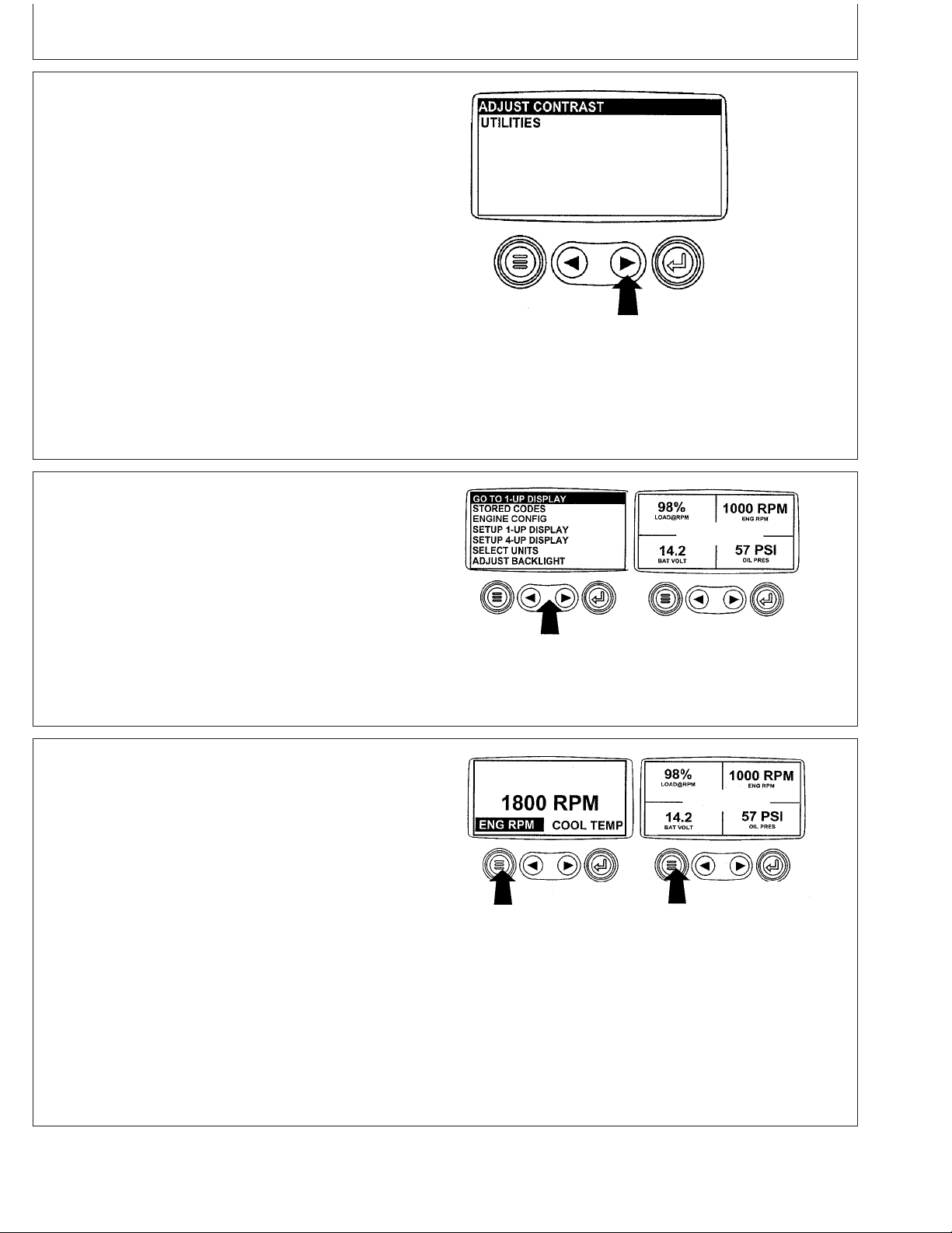
Instrument Panel - Elect. Cont. Later Engines
4. Pressing the right arrow key will scroll down to reveal
the last items of "Main Menu" screen, highlighting the
next item down.
5. Use the arrow keys to scroll to the desired menu item
or press the "Menu Button" to exit the main menu and
return to the engine parameter display.
Engine Configuration Data
Last Items On Main Menu
RG13162 –UN–26SEP03
OURGP11,00000A9 –19–27JUL06–4/5
RG13163 –UN–02OCT03
Use Arrow Buttons To Scroll / Quadrant Display
OURGP11,00000A9 –19–27JUL06–5/5
NOTE: The engine configuration data is a read only
function.
NOTE: The engine does not need to be running to
navigate the diagnostic gauge screens. If engine
start up is desired, See Starting The Engine. All of
the engine values illustrated on the diagnostic
gauge indicate the engine is running.
1. Turn the key switch to the ON position. Starting at the
single or four engine parameter display, press the
"Menu" key.
Continued on next page
17-6
Menu Key
RG13159 –UN–26SEP03
OURGP11,00000AB –19–27JUL06–1/6
080706
PN=69
Page 72
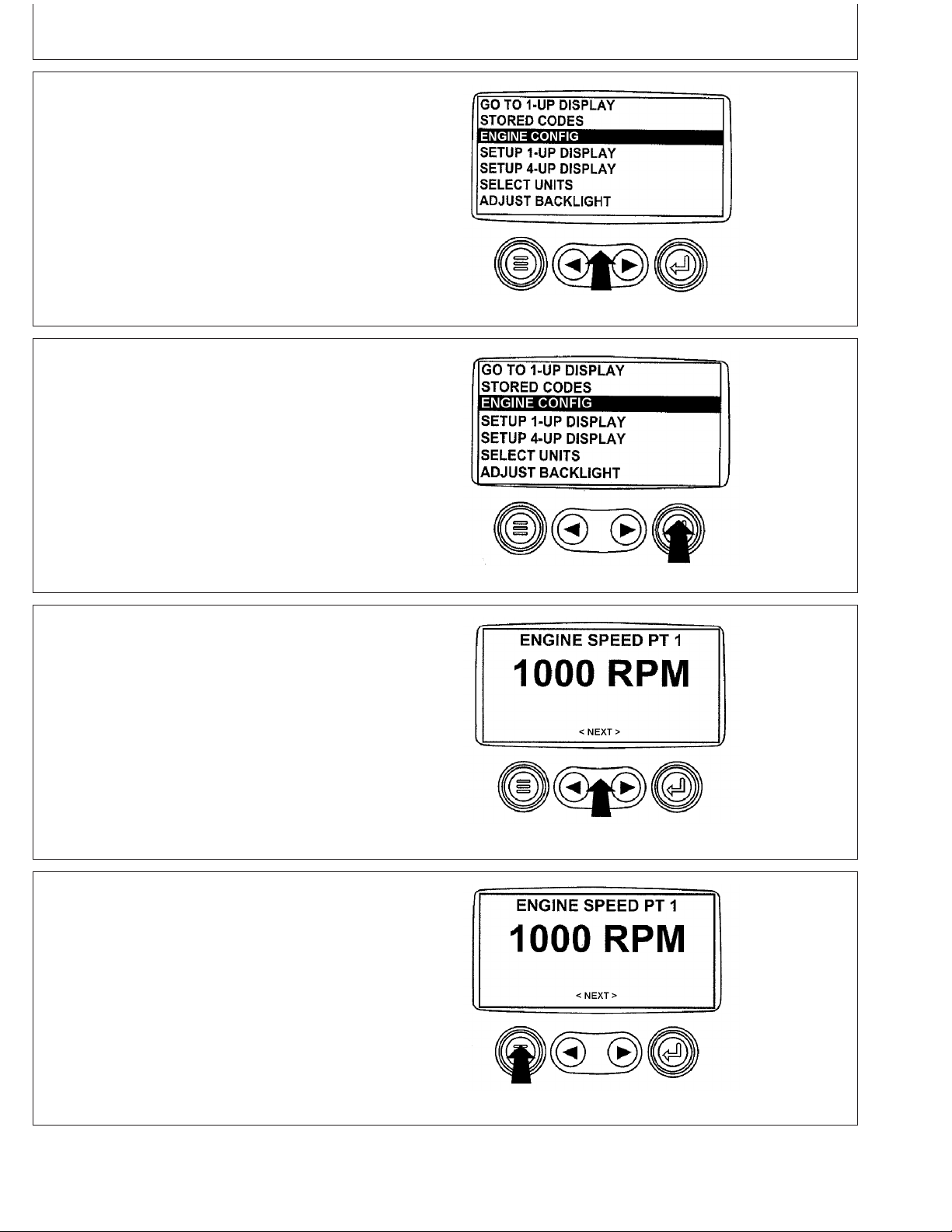
Instrument Panel - Elect. Cont. Later Engines
2. The main menu will be displayed. Use the "Arrow" keys
to scroll through the menu until "Engine Config" is
highlighted.
3. Once "Engine Config" menu item has been highlighted,
press the "Enter" key to view the engine configuration
data.
4. Use the "Arrow" keys to scroll through the engine
configuration data.
Select Engine Configuration
Enter Key
RG13164 –UN–07OCT03
OURGP11,00000AB –19–27JUL06–2/6
RG13165 –UN–02OCT03
OURGP11,00000AB –19–27JUL06–3/6
5. Press the "Menu" key to return to the main menu.
Continued on next page
17-7
Use Arrow Keys To Scroll
RG13166 –UN–29SEP03
OURGP11,00000AB –19–27JUL06–4/6
RG13167 –UN–29SEP03
Return To Main Menu
OURGP11,00000AB –19–27JUL06–5/6
080706
PN=70
Page 73

Instrument Panel - Elect. Cont. Later Engines
6. Press the "Menu" key to exit the main menu and return
to the engine parameter display.
Accessing Stored Trouble Codes
NOTE: The engine does not need to be running to
navigate the diagnostic gauge screens. If engine
start up is desired, See Starting The Engine. All of
the engine values illustrated on the diagnostic
gauge indicate the engine is running.
For description of trouble codes, see chart in
Troubleshooting Section.
1. Turn the key switch to the ON position. Starting at the
single or four engine parameter display, press the
"Menu" key.
Exit Main Menu
RG13159 –UN–26SEP03
OURGP11,00000AB –19–27JUL06–6/6
RG13159 –UN–26SEP03
Menu Key
2. The main menu will be displayed. Use the "Arrow" keys
to scroll through the menu until "Stored Codes" is
highlighted.
17-8
Select Stored Codes
Continued on next page
OURGP11,00000AC –19–27JUL06–1/6
RG13168 –UN–02OCT03
OURGP11,00000AC –19–27JUL06–2/6
080706
PN=71
Page 74

Instrument Panel - Elect. Cont. Later Engines
3. Once the "Stored Codes" menu item has been
highlighted press the "Enter" key to view the stored
codes.
4. If the word "Next" appears above the "Arrow" keys,
there are more stored codes that may be viewed. Use
the "Arrow" key to scroll to the next stored code.
Enter Key
RG13169 –UN–02OCT03
OURGP11,00000AC –19–27JUL06–3/6
RG13245 –UN–02OCT03
Use Arrow Keys To Scroll
OURGP11,00000AC –19–27JUL06–4/6
5. Press the "Menu" key to return to the main menu.
Continued on next page
17-9
Return To Main Menu
RG13246 –UN–02OCT03
OURGP11,00000AC –19–27JUL06–5/6
080706
PN=72
Page 75

Instrument Panel - Elect. Cont. Later Engines
6. Press the "Menu" key to exit the main menu and return
to the engine parameter display.
Accessing Active Trouble Codes
NOTE: The engine does not need to be running to
navigate the diagnostic gauge screens. If engine
start up is desired, See Starting The Engine. All of
the engine values illustrated on the diagnostic
gauge indicate the engine is running.
For description of trouble codes, see chart in
Troubleshooting Section.
1. During normal operation the single or four parameter
screen will be displayed.
Exit Main Menu
RG13159 –UN–26SEP03
OURGP11,00000AC –19–27JUL06–6/6
RG13172 –UN–26SEP03
Normal Operation
2. When the diagnostic gauge receives a trouble code
from an engine control unit, the single or four
parameter screen will be replaced with the "Warning"
message. The SPN and FMI number will be displayed
along with a description of the problem and the
corrective action needed.
IMPORTANT: Ignoring active trouble codes can result
in severe engine damage.
17-10
Active Trouble Codes Displayed
Continued on next page
OURGP11,00000AD –19–27JUL06–1/7
RG13240 –UN–30SEP03
OURGP11,00000AD –19–27JUL06–2/7
080706
PN=73
Page 76

Instrument Panel - Elect. Cont. Later Engines
3. If the word "Next" appears above the arrow keys, there
are more trouble codes that can be viewed by using
the arrow keys to scroll to the next trouble code.
IMPORTANT: Ignoring active trouble codes can result
in severe engine damage.
4. To acknowledge and hide the code and return to the
single or four parameter display, press the "Enter" Key.
5. The display will return to the single or four parameter
display, but the display will contain the warning icon.
Pressing the "Enter" key will redisplay the hidden
trouble code.
Use Arrow Keys To Scroll
RG13241 –UN–30SEP03
OURGP11,00000AD –19–27JUL06–3/7
RG13242 –UN–30SEP03
Hide Trouble Codes
OURGP11,00000AD –19–27JUL06–4/7
IMPORTANT: Ignoring active trouble codes can result
in severe engine damage.
6. Pressing the "Enter" key once again will hide the
trouble code and return the screen to the single or four
parameter display.
17-11
Continued on next page
Active Trouble Code Icon
RG13176 –UN–26SEP03
OURGP11,00000AD –19–27JUL06–5/7
RG13242 –UN–30SEP03
Enter Key
OURGP11,00000AD –19–27JUL06–6/7
080706
PN=74
Page 77

Instrument Panel - Elect. Cont. Later Engines
7. The single or four parameter screen will display the
warning icon until the trouble code condition is
corrected.
Engine Shutdown Codes
1. During normal operation the single or four parameter
screen will be displayed.
2. When the diagnostic gauge receives a severe trouble
code from an engine control unit, the single or four
parameter screen will be replaced with the "Shutdown"
message. The SPN and FMI number will be displayed
along with a description of the problem and the
corrective action needed.
Active Trouble Code Condition
RG13243 –UN–01OCT03
OURGP11,00000AD –19–27JUL06–7/7
RG13172 –UN–26SEP03
Normal Operation
OURGP11,00000AE –19–27JUL06–1/6
If the word "Next" appears above the arrow keys, there
are more trouble codes that can be viewed by using
the arrow keys to scroll to the next trouble code.
3. To acknowledge and hide the trouble code and return
to the single or four parameter display, press the
"Enter" key".
IMPORTANT: Ignoring the shutdown message can
result in severe engine damage.
17-12
Shutdown Message
Hide Trouble Code
Continued on next page
RG13238 –UN–29SEP03
OURGP11,00000AE –19–27JUL06–2/6
RG13239 –UN–29SEP03
OURGP11,00000AE –19–27JUL06–3/6
080706
PN=75
Page 78

Instrument Panel - Elect. Cont. Later Engines
4. The display will return to the single or four parameter
display, but the display will contain the "Shutdown"
icon. Pressing the "Enter" key will redisplay the hidden
trouble code.
IMPORTANT: Ignoring the shutdown message can
result in severe engine damage.
5. Pressing the "Enter" key once again will hide the
trouble code and return the screen to the single or four
parameter display.
Flashing Shutdown Icon
RG13179 –UN–26SEP03
OURGP11,00000AE –19–27JUL06–4/6
6. The single or four parameter screen will display the
shutdown icon until the trouble code condition is
corrected.
IMPORTANT: Ignoring the shutdown message can
result in severe engine damage.
Adjusting Backlighting
1. Turn the key switch to the ON position. Starting at the
single or four engine parameter display, press the
"Menu" key.
Redisplay Trouble Code
RG13239 –UN–29SEP03
OURGP11,00000AE –19–27JUL06–5/6
RG13180 –UN–26SEP03
Shutdown Icon
OURGP11,00000AE –19–27JUL06–6/6
Continued on next page
17-13
Menu Key
RG13159 –UN–26SEP03
OURGP11,0000237 –19–27JUL06–1/6
080706
PN=76
Page 79

Instrument Panel - Elect. Cont. Later Engines
2. The main menu will be displayed. Use the "Arrow" keys
to scroll through the menu until "Adjust Backlight" is
highlighted.
3. Once the "Adjust Backlight" menu item has been
highlighted, press the "Enter" key to activate the
"Adjust Backlight" function.
4. Use the "Arrow" keys to select the desired backlight
intensity.
Select Adjust Backlight
Press Enter Key
RG13181 –UN–02OCT03
OURGP11,0000237 –19–27JUL06–2/6
RG13182 –UN–02OCT03
OURGP11,0000237 –19–27JUL06–3/6
Continued on next page
17-14
Adjust Backlight Intensity
RG13183 –UN–29SEP03
OURGP11,0000237 –19–27JUL06–4/6
080706
PN=77
Page 80
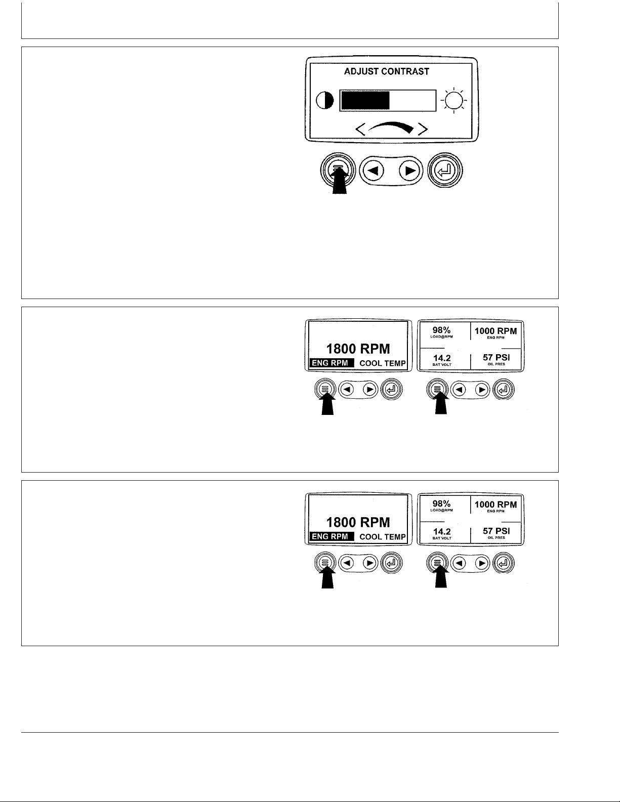
Instrument Panel - Elect. Cont. Later Engines
5. Press the "Menu" key to return to the main menu.
6. Press the "Menu" key to exit the main menu and return
to the engine parameter display.
Return To Main Menu
RG13184 –UN–26SEP03
OURGP11,0000237 –19–27JUL06–5/6
RG13159 –UN–26SEP03
Exit Main Menu
OURGP11,0000237 –19–27JUL06–6/6
Adjusting Contrast
1. Turn the key switch to the ON position. Starting at the
single or four engine parameter display press the
"Menu" key.
17-15
Continued on next page
Menu Key
RG13159 –UN–26SEP03
OURGP11,00000AF –19–27JUL06–1/6
080706
PN=78
Page 81
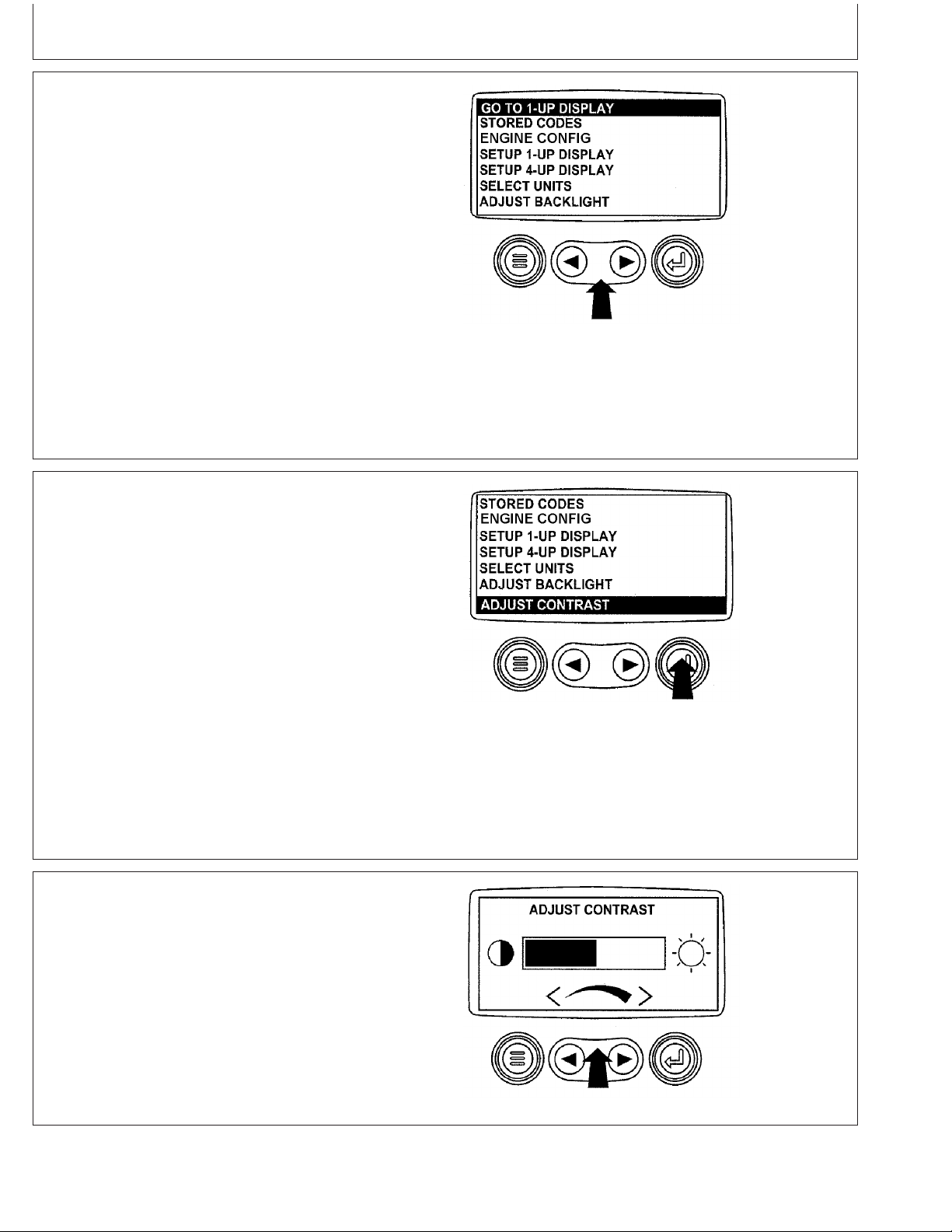
Instrument Panel - Elect. Cont. Later Engines
2. The main menu will be displayed. Use the "Arrow" keys
to scroll through the menu until "Adjust Contrast" is
highlighted.
3. Once the "Adjust Contrast" menu item has been
highlighted, press the "Enter" key to activate the
"Adjust Contrast" function.
Select Adjust Contrast
RG13161 –UN–02OCT03
OURGP11,00000AF –19–27JUL06–2/6
RG13185 –UN–02OCT03
Press Enter Key
4. Use the "Arrow" keys to select the desired contrast
intensity.
Continued on next page
17-16
Adjust Contrast Intensity
OURGP11,00000AF –19–27JUL06–3/6
RG13186 –UN–29SEP03
OURGP11,00000AF –19–27JUL06–4/6
080706
PN=79
Page 82

Instrument Panel - Elect. Cont. Later Engines
5. Press the "Menu" key to return to the main menu.
6. Press the "Menu" key to exit the main menu and return
to the engine parameter display.
Return To Main Menu
RG13187 –UN–26SEP03
OURGP11,00000AF –19–27JUL06–5/6
RG13159 –UN–26SEP03
Exit Main Menu
OURGP11,00000AF –19–27JUL06–6/6
Selecting Units Of Measurement
1. Turn the key switch to the ON position. Starting at the
single or four engine parameter display, press the
"Menu" key.
17-17
Continued on next page
Menu Key
RG13159 –UN–26SEP03
OURGP11,00000B0 –19–27JUL06–1/7
080706
PN=80
Page 83
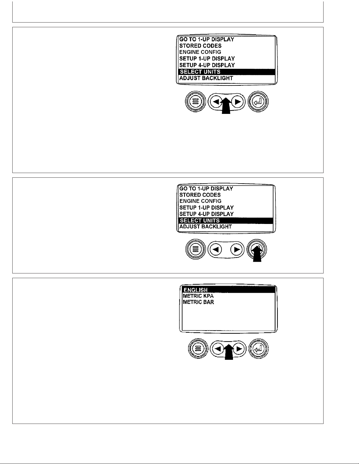
Instrument Panel - Elect. Cont. Later Engines
2. The main menu will be displayed. Use the "Arrow" keys
to scroll through the menu until "Select Units" is
highlighted.
3. Once the "Select Units" menu item has been
highlighted press the "Enter" key to access the "Select
Units" function.
Select Units
Press Enter Key
RG13188 –UN–02OCT03
OURGP11,00000B0 –19–27JUL06–2/7
RG13189 –UN–02OCT03
OURGP11,00000B0 –19–27JUL06–3/7
4. There are three choices for units of measurement,
English, Metric kPa or Metric Bar.
English is for Imperial units, with pressures displayed
in PSI and temperatures in °F.
Metric kPa and Metric bar are for IS units, with
pressures displayed in kPa and bar respectively, and
temperatures in °C.
Use the "Arrow" keys to highlight the desired units of
measurement.
Continued on next page
17-18
Select Desired Units
RG13190 –UN–26SEP03
OURGP11,00000B0 –19–27JUL06–4/7
080706
PN=81
Page 84
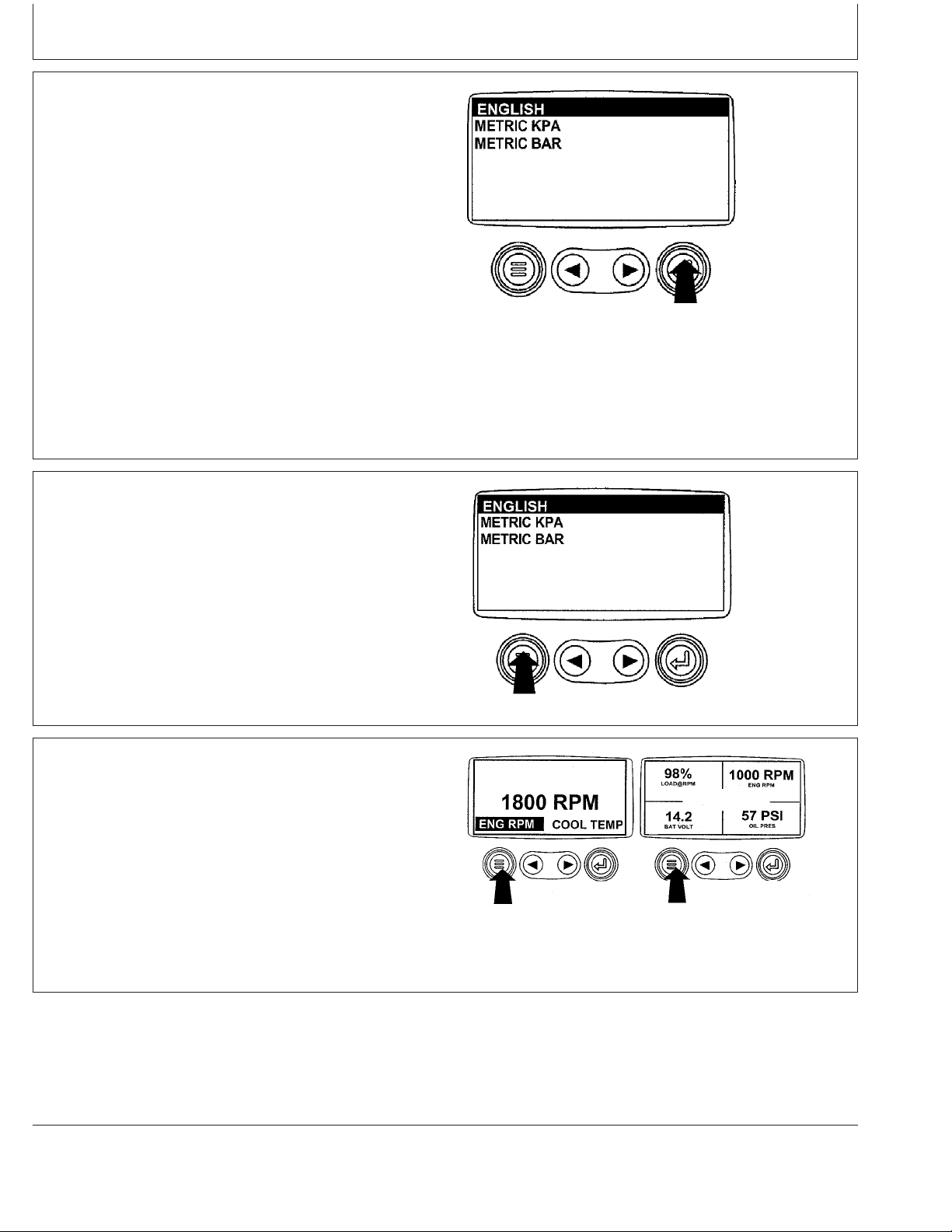
Instrument Panel - Elect. Cont. Later Engines
5. Press the "Enter" key to select the highlighted units.
6. Press the "Menu" key to return to the main menu.
Press Enter Key to Select
Return To Main Menu
RG13191 –UN–30SEP03
OURGP11,00000B0 –19–27JUL06–5/7
RG13192 –UN–26SEP03
OURGP11,00000B0 –19–27JUL06–6/7
7. Press the "Menu" key to return to the engine
parameter display.
17-19
Press Menu Key
RG13159 –UN–26SEP03
OURGP11,00000B0 –19–27JUL06–7/7
080706
PN=82
Page 85
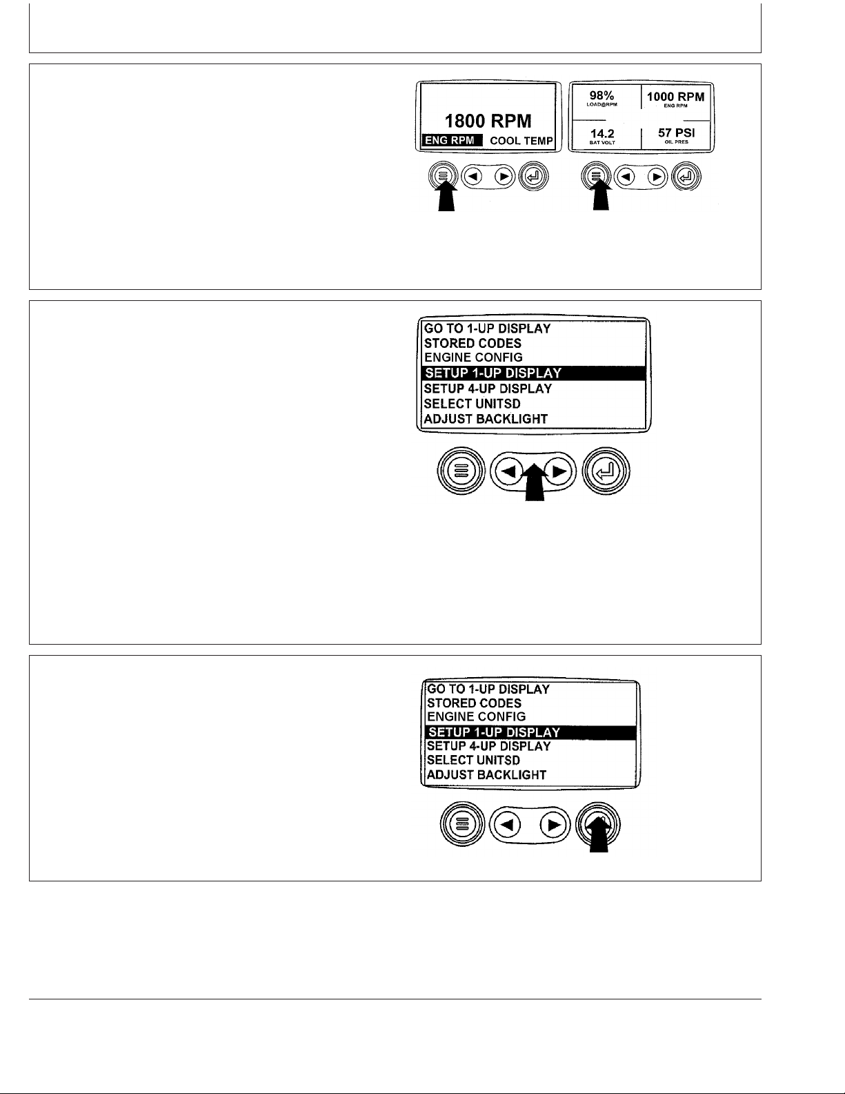
Instrument Panel - Elect. Cont. Later Engines
Setup 1-Up Display
1. Turn the key switch to the ON position. Starting at the
single engine parameter display, press the "Menu" key.
2. Use the "Arrow" keys to scroll through the menu until
"Setup 1-Up Display" is highlighted.
Menu Key
RG13159 –UN–26SEP03
OURGP11,00000B1 –19–27JUL06–1/18
RG13193 –UN–02OCT03
Setup 1-Up Display
3. Once "Setup 1-Up Display" menu item has been
highlighted press the "Enter" key to access the "Setup
1-Up Display" function.
Continued on next page
17-20
Press Enter Key
OURGP11,00000B1 –19–27JUL06–2/18
RG13194 –UN–02OCT03
OURGP11,00000B1 –19–27JUL06–3/18
080706
PN=83
Page 86
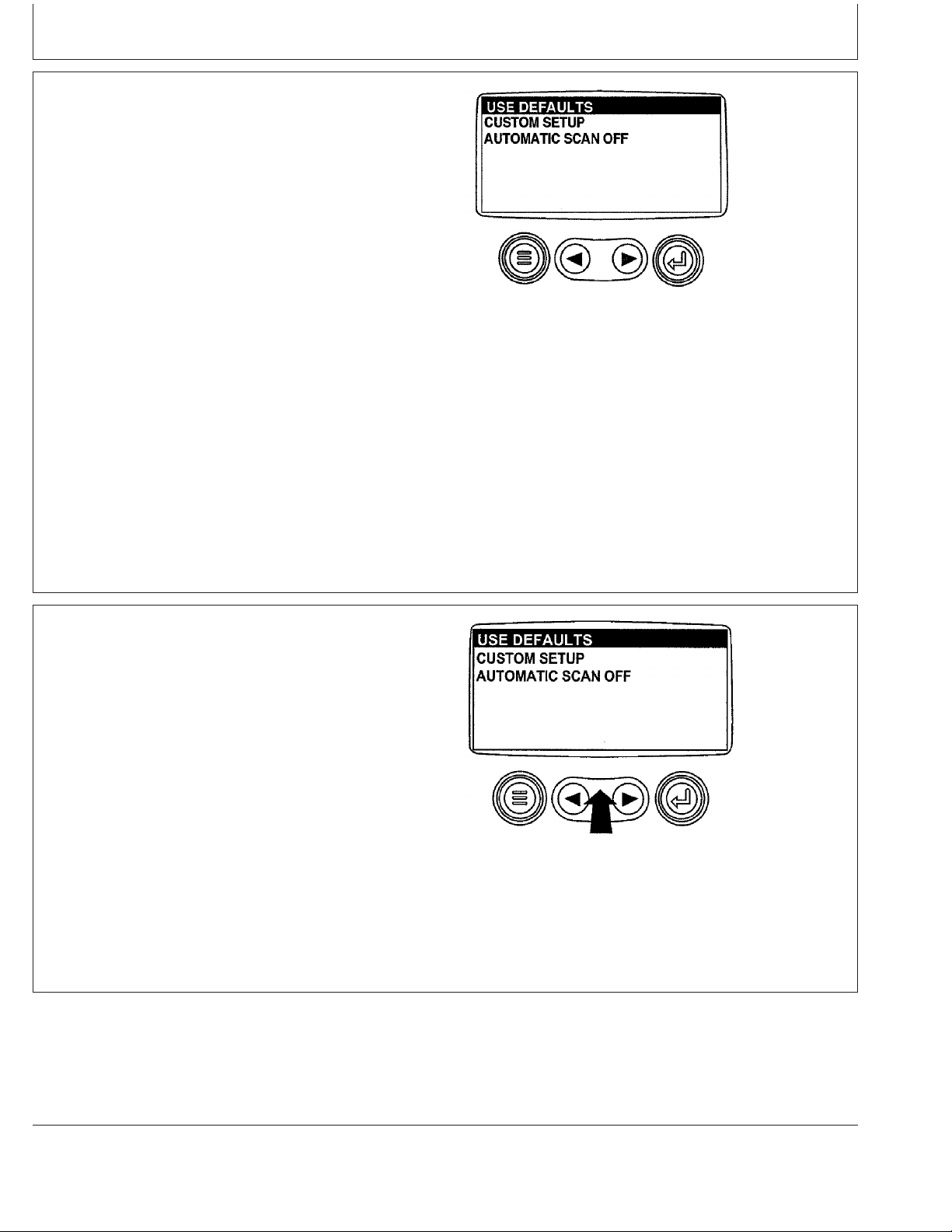
Instrument Panel - Elect. Cont. Later Engines
4. Three options are available for modification of the 1-Up
Display.
a. Use Defaults – This option contains the following
engine parameters for display: Engine Hours,
Engine Speed, Battery Voltage, % Load, Coolant
Temperature and Oil Pressure.
b. Custom Setup – This option contains a list of
engine parameters. Engine parameters from this list
can be selected to replace any or all of the default
parameters. This option can be used to add
parameters available for scrolling in the 1-Up
Display.
c. Automatic Scan – Selecting the scan function will
allow the 1-Up Display to scroll through the selected
set of parameters one at a time, momentarily
pausing at each.
1-Up Display Options
RG13196 –UN–26SEP03
5. Use Defaults - To select "Use Defaults" use the Arrow
keys to scroll to and highlight "Use Defaults" in the
menu display.
Continued on next page
OURGP11,00000B1 –19–27JUL06–4/18
RG13195 –UN–26SEP03
Select Defaults
OURGP11,00000B1 –19–27JUL06–5/18
17-21
080706
PN=84
Page 87
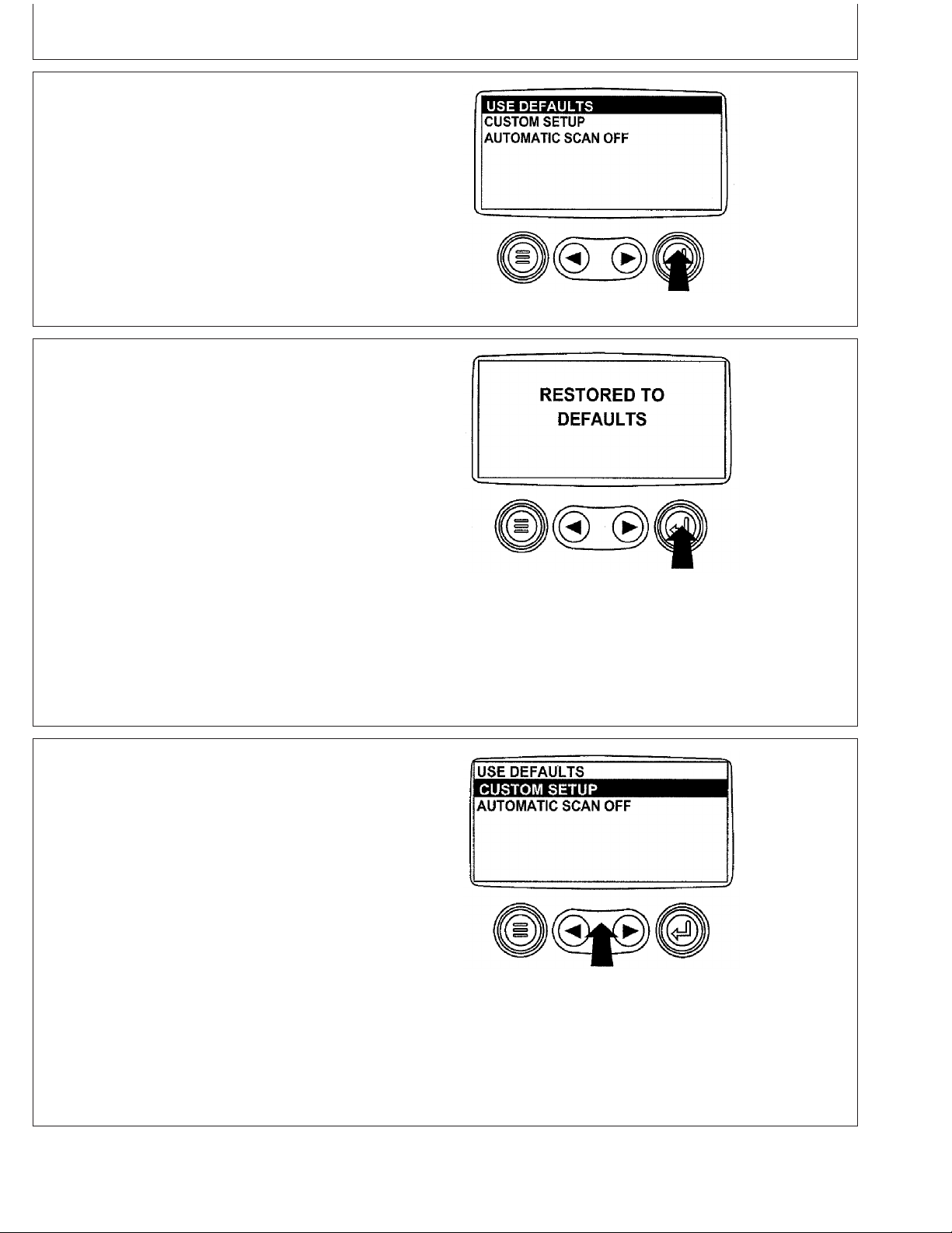
Instrument Panel - Elect. Cont. Later Engines
6. Press the "Enter" key to activate the "Use Defaults"
function.
7. The display parameters are reset to the factory
defaults, then the display will return to the "Setup 1-Up
Display" menu.
Defaults Selected
RG13197 –UN–29SEP03
OURGP11,00000B1 –19–27JUL06–6/18
RG13149 –UN–24SEP03
Restored To Defaults
OURGP11,00000B1 –19–27JUL06–7/18
8. Custom Setup - To perform a custom setup of the
1-Up Display, use the arrow buttons to scroll to and
highlight "Custom Setup" on the display.
Continued on next page
17-22
Select Custom Setup
RG13198 –UN–26SEP03
OURGP11,00000B1 –19–27JUL06–8/18
080706
PN=85
Page 88
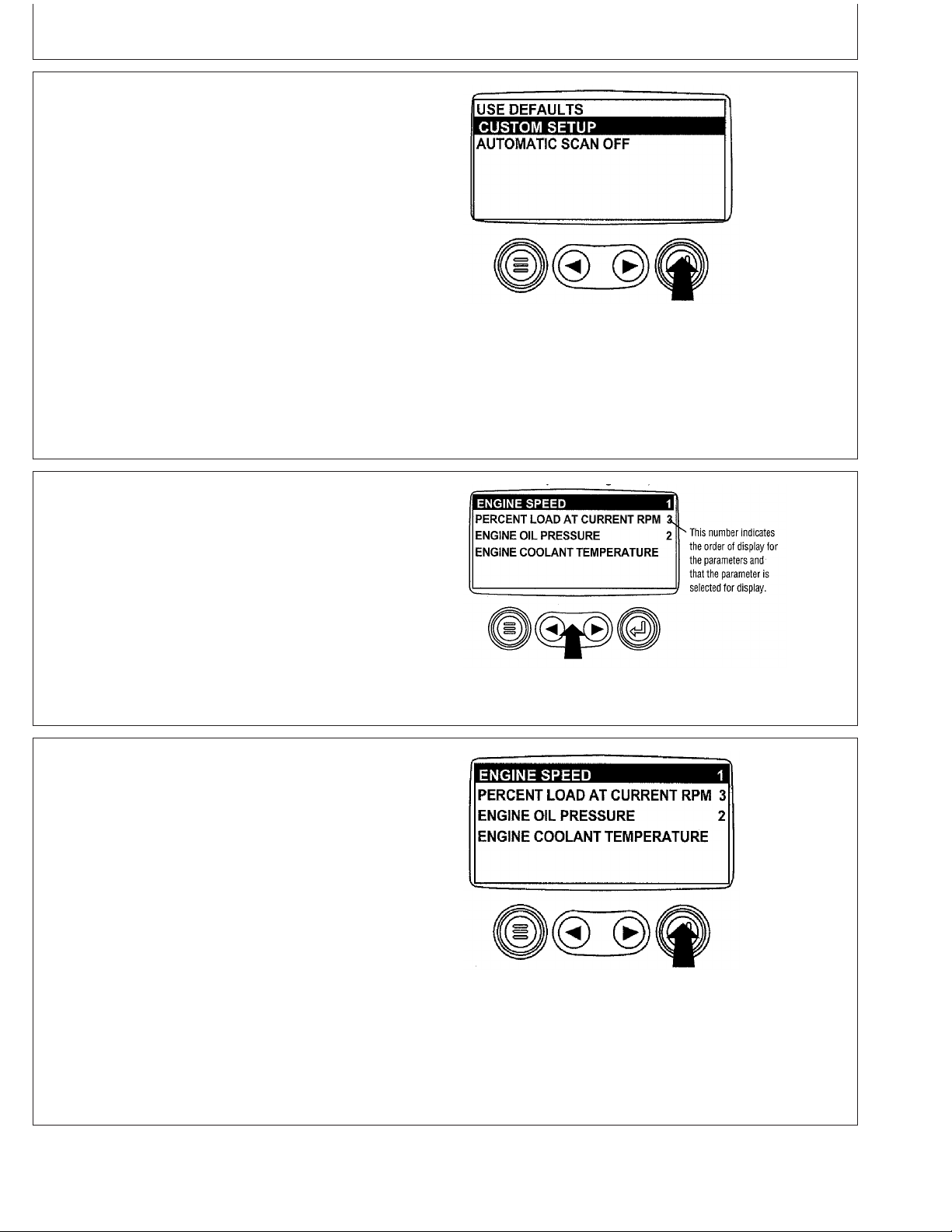
Instrument Panel - Elect. Cont. Later Engines
9. Press the "Enter" key to display a list of engine
parameters.
10. Use the "Arrow" keys to scroll to and highlight a
selected parameter (parameter with a number to right
of it).
Engine Parameters
RG13199 –UN–26SEP03
OURGP11,00000B1 –19–27JUL06–9/18
RG13150 –UN–24SEP03
Select Parameters
OURGP11,00000B1 –19–27JUL06–10/18
11. Press the "Enter" key to deselect the selected
parameter, removing it from the list of parameters
being displayed on the 1-Up Display.
Continued on next page
17-23
Deselect Parameters
RG13219 –UN–26SEP03
OURGP11,00000B1 –19–27JUL06–11/18
080706
PN=86
Page 89
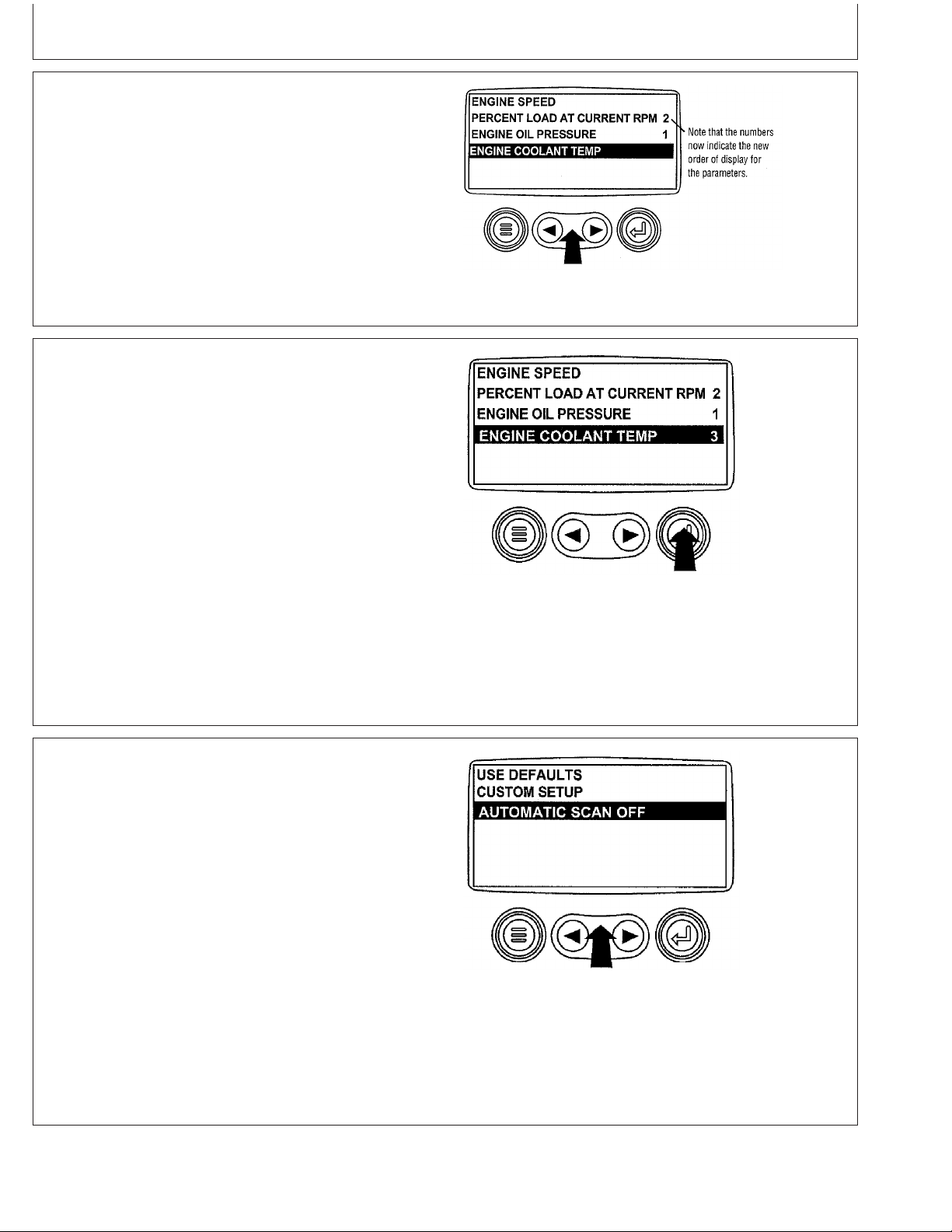
Instrument Panel - Elect. Cont. Later Engines
12. Use the "Arrow" keys to scroll and highlight the
desired parameter that has not been selected for
display (parameter without a number to right of it).
13. Press the "Enter" key to select the parameter for
inclusion in the Single Engine Parameter Display.
14. Continue to scroll through and select additional
parameters for the custom 1-Up Display. Press the
"Menu" key at any time to return to the "Custom
Setup" menu.
Select Desired Parameters
RG13151 –UN–24SEP03
OURGP11,00000B1 –19–27JUL06–12/18
RG13220 –UN–26SEP03
Select Parameters For Display
15. Automatic Scan - Selecting the scan function will
allow the 1- Up Display to scroll through the selected
set of parameters one at a time. Use the "Arrow" keys
to scroll to the "Automatic Scan" function.
Continued on next page
17-24
OURGP11,00000B1 –19–27JUL06–13/18
RG13221 –UN–26SEP03
Automatic Scan Off
OURGP11,00000B1 –19–27JUL06–14/18
080706
PN=87
Page 90

Instrument Panel - Elect. Cont. Later Engines
16. Press the "Enter" key to toggle the "Automatic Scan"
function on.
17. Press the "Enter" key again to toggle the "Automatic
Scan" function off.
Automatic Scan On
RG13222 –UN–26SEP03
OURGP11,00000B1 –19–27JUL06–15/18
RG13223 –UN–26SEP03
Automatic Scan Off
Continued on next page
17-25
OURGP11,00000B1 –19–27JUL06–16/18
080706
PN=88
Page 91
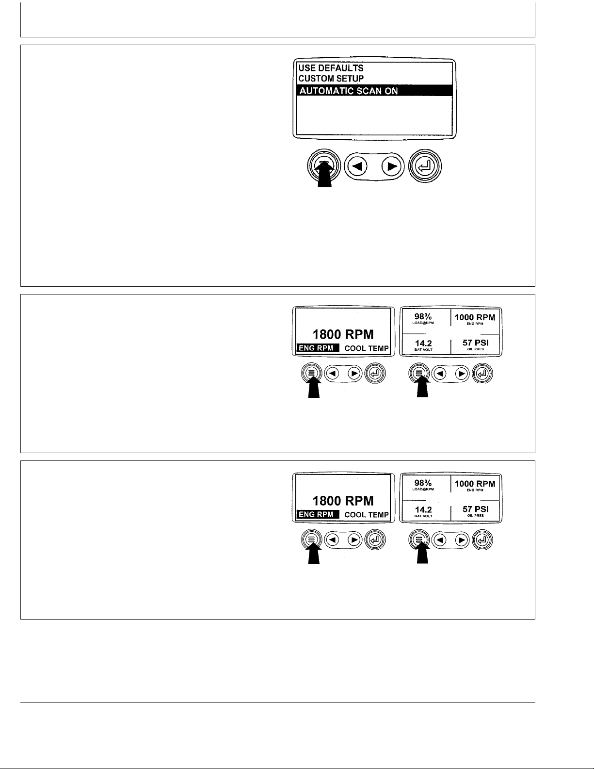
Instrument Panel - Elect. Cont. Later Engines
18. Once the "Use Defaults", "Custom Setup" and
"Automatic Scan" functions have been set, press the
"Menu" key to return to the main menu.
19. Press the "Menu" key to exit the main menu and
return to the engine parameter display.
Menu Key
RG13224 –UN–26SEP03
OURGP11,00000B1 –19–27JUL06–17/18
RG13159 –UN–26SEP03
Exit Main Menu
OURGP11,00000B1 –19–27JUL06–18/18
Setup 4-Up Display
1. Turn the key switch to the ON position. From the single
or four engine parameter display, press the "Menu"
key.
17-26
Continued on next page
Menu Key
RG13159 –UN–26SEP03
OURGP11,00000B2 –19–27JUL06–1/14
080706
PN=89
Page 92

Instrument Panel - Elect. Cont. Later Engines
2. The main menu will be displayed. Use the "Arrow" keys
to scroll through the menu until "Setup 4-Up Display" is
highlighted.
3. Once the "Setup 4-Up Display" menu item has been
highlighted, press the "Enter" key to activate the "Setup
4-Up Display" menu.
Select Setup 4-Up Display
RG13225 –UN–02OCT03
OURGP11,00000B2 –19–27JUL06–2/14
RG13226 –UN–02OCT03
Press Enter Key
Continued on next page
17-27
OURGP11,00000B2 –19–27JUL06–3/14
080706
PN=90
Page 93

Instrument Panel - Elect. Cont. Later Engines
4. Two options are available for the 4-Up Display.
a. Use Defaults – This option contains the following
engine parameters for display: Engine Speed,
Battery Voltage, Coolant Temperature and Oil
Pressure.
b. Custom Setup – This option contains a list of
engine parameters. Engine parameters from this list
can be selected to replace any or all of the default
parameters.
Select Factory Defaults
RG13244 –UN–02OCT03
OURGP11,00000B2 –19–27JUL06–4/14
5. To reset the display parameters to the factory defaults,
scroll to and highlight "Use Defaults". Press the "Enter"
key to activate the "Use Defaults" function. A message
indicating the display parameters are reset to the
factory defaults will be displayed, then the display will
return to the "Setup 4-Up Display" menu.
6. Custom Setup - To perform a custom setup of the
4-Up Display, use the arrow buttons to scroll to and
highlight "Custom Setup" on the display.
Restored To Defaults
RG13149 –UN–24SEP03
OURGP11,00000B2 –19–27JUL06–5/14
Continued on next page
17-28
Custom Setup
RG13227 –UN–26SEP03
OURGP11,00000B2 –19–27JUL06–6/14
080706
PN=91
Page 94

Instrument Panel - Elect. Cont. Later Engines
7. The quadrant with the highlighted parameter value is
the current selected parameter. Use the "Arrow" keys
to highlight the value in the quadrant you wish to
change to a new parameter.
8. Press the "Enter" key and a list of engine parameters
will be displayed.
Select Parameters
RG13228 –UN–26SEP03
OURGP11,00000B2 –19–27JUL06–7/14
RG13229 –UN–26SEP03
List Of Engine Parameters
OURGP11,00000B2 –19–27JUL06–8/14
9. The parameter that is highlighted is the selected
parameter for the screen. Use the "arrow" keys to
highlight the new parameter to be placed in the "4-Up
Display".
Continued on next page
17-29
Select Desired Engine Parameter
RG13230 –UN–26SEP03
OURGP11,00000B2 –19–27JUL06–9/14
080706
PN=92
Page 95

Instrument Panel - Elect. Cont. Later Engines
10. Press the "Enter" key to change the selected
parameter in the quadrant to the new parameter.
11. Use the "Menu" keys to return to the "4-Up Custom
Setup" screen.
12. The selected quadrant has now changed to the new
selected parameter.
Enter Selected Parameter
Return To 4-Up Custom Setup
RG13231 –UN–26SEP03
OURGP11,00000B2 –19–27JUL06–10/14
RG13232 –UN–26SEP03
OURGP11,00000B2 –19–27JUL06–11/14
Continued on next page
17-30
4-Up Display
RG13153 –UN–24SEP03
OURGP11,00000B2 –19–27JUL06–12/14
080706
PN=93
Page 96
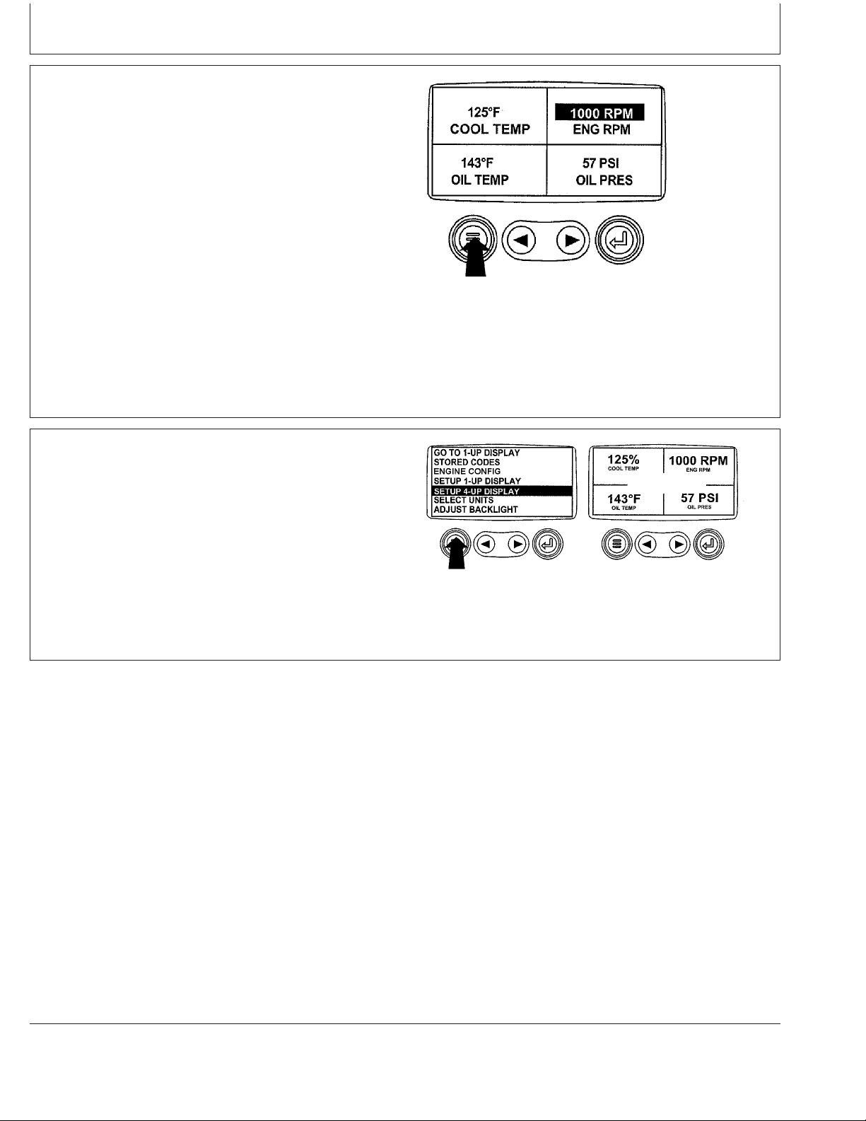
Instrument Panel - Elect. Cont. Later Engines
13. Repeat the parameter selection process until all
spaces are as desired.
14. Press the "Menu" key to return to the main menu.
15. Press the "Menu" key to exit the main menu and
return to the engine parameter display.
Return To Main Menu
RG13154 –UN–24SEP03
OURGP11,00000B2 –19–27JUL06–13/14
RG13155 –UN–07OCT03
Select Remaining Parameters
OURGP11,00000B2 –19–27JUL06–14/14
17-31
080706
PN=94
Page 97
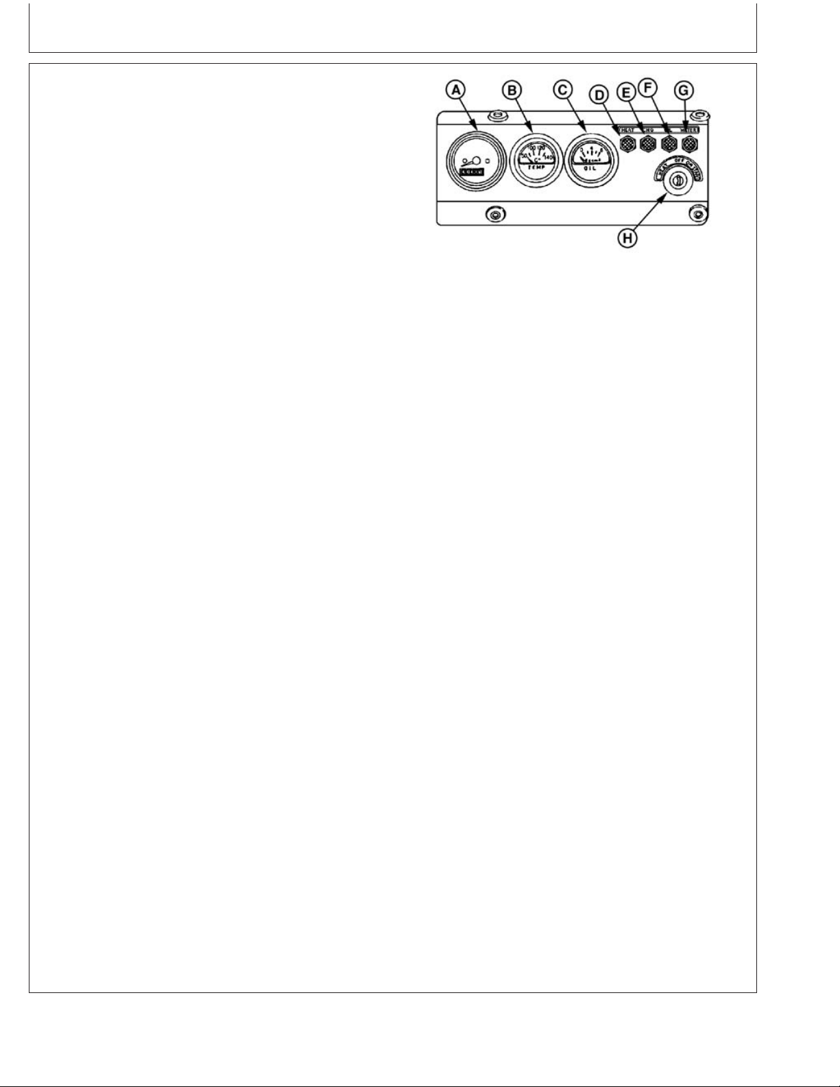
Instrument Panel - Mech. Cont. “270” Engines
Instrument Panel (Earlier 4.5 L “270”
Engines)
All controls and gauges are optional equipment for John
Deere 4.5 L suffix “270” OEM Engines. They may be
provided by the equipment manufacturer instead of John
Deere.
IMPORTANT: Any time an electric gauge or meter
does not register correctly, replace it
with a new one. Do not attempt to repair
it.
Instrument Panel and Gauges (Earlier 4.5 L “270” Engines)
RG6574A –UN–07JAN03
Following is a brief description of the components on a
basic instrument (gauge) panel:
A—Tachometer with Hourmeter - The optional
tachometer with hourmeter indicates engine speed in
revolutions per minute (rpm) and shows the operating
hours of the engine while key switch is in the “ON”
position. The hour meter should be used as a guide for
scheduling periodic service.
B—Coolant Temperature Gauge - The coolant
temperature gauge indicates the engine coolant
temperature. It is connected to a warning lamp to warn
the operator if coolant temperature rises above the preset,
safe operating temperature.
C—Oil Pressure Gauge - The oil pressure gauge
indicates engine oil pressure. It is connected to a warning
lamp to warn the operator if engine oil pressure falls
below a safe operating pressure.
D—Pre-Heat Indicator Lamp - This indicator lamp is
initially turned on when the key switch is turned to the
“HEAT” position to activate the preheater for cold weather
starting. Lamp is connected to a timer that turns the lamp
off after 15 seconds when the key switch is held at
“HEAT” position. When the lamp goes out, start the
engine.
A—Tachometer with Hourmeter
B—Coolant Temperature Gauge
C—Oil Pressure Gauge
D—Pre-Heat Indicator Lamp
E—Charge Indicator Lamp
F—Oil Pressure Indicator Lamp
G—Coolant Temperature Indicator Lamp
H—Key Switch
E—Charge Indicator Lamp - Indicates whether the
charging circuit is adequately replacing battery voltage as
it is used by the electrical system. If the lamp is lit while
the engine is running above 1300 rpm, stop engine
immediately and check charging circuit.
18-1
Continued on next page
OURGP11,000018E –19–27JUL06–1/2
080706
PN=95
Page 98

Instrument Panel - Mech. Cont. “270” Engines
F—Oil Pressure Indicator Lamp - Warns operator that
engine oil pressure is below a safe operating level. If lamp
stays lit while engine is running faster than slow idle, stop
engine immediately and check engine oil level.
G—Coolant Temperature Indicator Lamp - Warns
operator that engine coolant temperature exceeds safe
operating level. If lamp is lit during full load operation, the
engine is overheated. Stop engine and immediately check
fan belt tension and coolant level in radiator.
H—Key Switch - The key switch controls the electrical
system. Positions of key switch are marked as follows:
OFF, ON, and START. There is also a HEAT position for
cold weather starting.
Instrument Panel and Gauges (4.5 L “270” Engines)
RG6574A –UN–07JAN03
OURGP11,000018E –19–27JUL06–2/2
18-2
080706
PN=96
Page 99
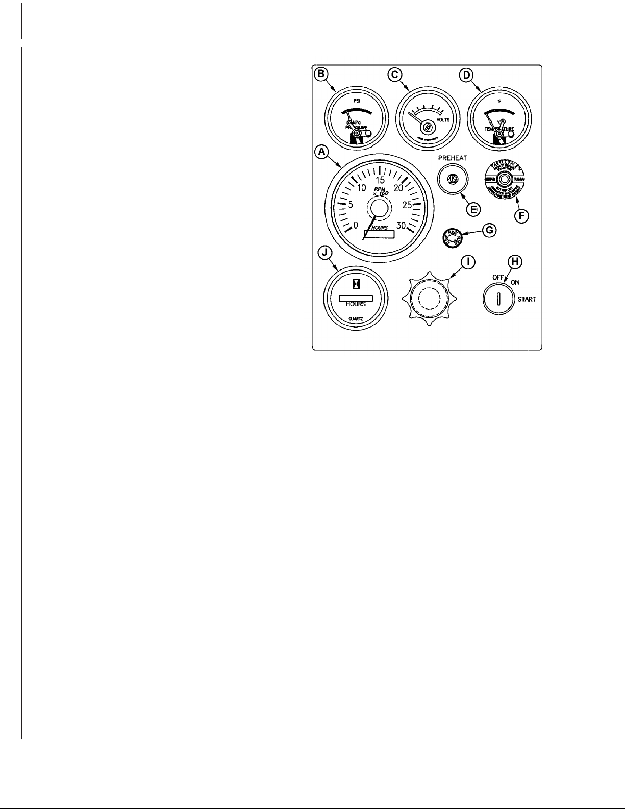
Instrument Panel - Mech. Cont. “270” Engines
Instrument Panel (Later 4.5 L “270” Engines)
All controls and gauges are optional equipment for John
Deere 4.5 L suffix “270” OEM Engines. They may be
provided by the equipment manufacturer instead of John
Deere.
IMPORTANT: Any time an electric gauge or meter
does not register correctly, replace it
with a new one. Do not attempt to repair
it.
Following is a brief description of the components on a
basic instrument (gauge) panel:
A—Tachometer with Hourmeter (Optional) - The
tachometer with hourmeter indicates engine speed in
revolutions per minute (rpm) and shows the operating
hours of the engine while key switch is in the “ON”
position. The hour meter should be used as a guide for
scheduling periodic service.
B—Oil Pressure Gauge - The oil pressure gauge
indicates engine oil pressure. If the engine oil pressure
falls below a safe operating pressure, the engine will shut
down.
C—Voltmeter Gauge - The voltmeter indicates system
battery voltage.
D—Coolant Temperature Gauge - The coolant
temperature gauge indicates the engine coolant
temperature. If coolant temperature rises above the
preset, safe operating temperature, the engine will shut
down.
E—Pre-Heat Button - Press button to activate the
preheater for cold weather starting.
F—Reset (Safety) Switch- Reset button will pop out and
shut down the engine if the coolant temperature is too
high or oil pressure is too low. Press in and hold while
starting engine until oil pressure is at a safe operating
level.
G—Fuse Holder - Contains 14 amp fuse.
Instrument Panel and Gauges (Later 4.5 L “270” Engines)
RG13360 –UN–06FEB04
A—Tachometer with Hourmeter (Optional)
B—Oil Pressure Gauge
C—Voltmeter Gauge
D—Coolant Temperature Gauge
E—Preheat Button
F—Reset (Safety) Switch
G—Fuse Holder
H—Key Switch
I—Throttle (Optional)
J—Hourmeter (Optional)
Continued on next page
18-3
OURGP11,0000160 –19–27JUL06–1/2
080706
PN=97
Page 100

Instrument Panel - Mech. Cont. “270” Engines
H—Key Switch - The key switch controls the electrical
system. Positions of key switch are marked as follows:
OFF, ON, and START.
I—Throttle (Optional) - The throttle control is used to
control engine speed.
J—Hourmeter (Optional) - The hourmeter indicates the
operating hours of the engine while key switch is in the
“ON” position. The hour meter should be used as a guide
for scheduling periodic service.
OURGP11,0000160 –19–27JUL06–2/2
18-4
080706
PN=98
 Loading...