

Jenn-Air JDRP436WP03, JDRP536WP03, JDRP548WP03 Installation Guide

INSTALLATION INSTRUCTIONS
CommerCial-Style Dual Fuel ConveCtion rangeS
30" (76.2 Cm), 36" (91.4 Cm), anD 48" (121.9 Cm)
For residential use only
INSTRUCTIONS D’INSTALLATION
CuiSinièreS à ConveCtion à Double CombuStible De type CommerCial
30" (76,2 Cm), 36" (91,4 Cm), et 48" (121,9 Cm)
Pour utilisation résidentielle uniquement
Table of Contents/Table des matières
RANGE SAFETY .............................................................................2
INSTALLATION REQUIREMENTS .................................................4
Tools and Parts .............................................................................4
Location Requirements ................................................................6
Electrical Requirements: U.S.A. Only ..........................................8
Electrical Requirements: Canada Only ........................................9
Gas Supply Requirements ...........................................................9
INSTALLATION INSTRUCTIONS .................................................11
Unpack the Range .....................................................................11
Install Optional Backguard .........................................................12
Install Anti-Tip Bracket ...............................................................12
Electrical Connection: U.S.A. Only ............................................13
Make Gas Connection ...............................................................14
Verify Anti-Tip Bracket Location ................................................15
Level Range ................................................................................15
Install Griddle .............................................................................15
Electronic Ignition System .........................................................16
Reinstall Kick Plate .....................................................................17
Complete Installation .................................................................18
GAS CONVERSIONS ....................................................................18
Propane Gas Conversion ...........................................................18
Natural Gas Conversion .............................................................20
SÉCURITÉ DE LA CUISINIÈRE ...................................................22
EXIGENCES D’INSTALLATION ...................................................24
Outillage et pièces ......................................................................24
Exigences d’emplacement .........................................................26
Spécifications de l’installation électrique ..................................28
Spécifications de l’alimentation en gaz .....................................28
INSTRUCTIONS D’INSTALLATION .............................................30
Déballage de la cuisinière ..........................................................30
Installation du dosseret facultatif ...............................................31
Installation de la bride antibasculement ....................................31
Raccordement au gaz ................................................................32
Vérification de l’emplacement de la bride antibasculement .....32
Réglage de l’aplomb de la cuisinière .........................................33
Installation de la plaque à frire ...................................................33
Système d’allumage électronique..............................................33
Réinstallation du garde-pieds ....................................................35
Achever l’installation ..................................................................35
CONVERSIONS POUR CHANGEMENT DE GAZ ......................36
Conversion pour l’alimentation au propane ..............................36
Conversion pour l’alimentation au gaz naturel ..........................38
IMPORTANT:
Save for local electrical inspector’s use.
Installer: Leave installation instructions with the homeowner.
Homeowner: Keep installation instructions for future reference.
IMPORTANT :
À conserver pour consultation par l’inspecteur local des installations électriques.
Installateur : Remettre les instructions d’installation au propriétaire.
Propriétaire : Conserver les instructions d’installation pour référence ultérieure.
W11090454B www.jennair.com (U.S.A.) www.jennair.ca (Canada)
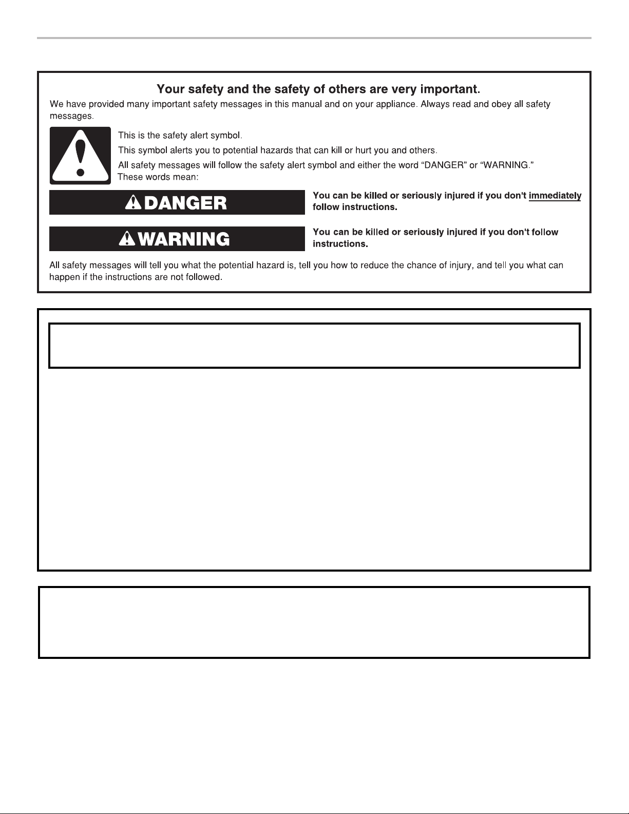
RANGE SAFETY
WARNING: If the information in these instructions is not followed exactly, a fire or
explosion may result causing property damage, personal injury or death.
– Do not store or use gasoline or other flammable vapors and liquids in the vicinity of this
or any other appliance.
– WHAT TO DO IF YOU SMELL GAS:
Do not try to light any appliance.
•
Do not touch any electrical switch.
•
Do not use any phone in your building.
•
Immediately call your gas supplier from a neighbor's phone. Follow the gas supplier's
•
instructions.
If you cannot reach your gas supplier, call the fire department.
•
– Installation and service must be performed by a qualified installer, service agency or
the gas supplier.
WARNING: Gas leaks cannot always be detected by smell.
Gas suppliers recommend that you use a gas detector approved by UL or CSA.
For more information, contact your gas supplier.
If a gas leak is detected, follow the “What to do if you smell gas” instructions.
2
IMPORTANT: Do not install a ventilation system that blows air downward toward this gas cooking appliance. This type of
ventilation system may cause ignition and combustion problems with this gas cooking appliance resulting in personal injury or
unintended operation.
In the State of Massachusetts, the following installation instructions apply:
■ Installations and repairs must be performed by a qualified or licensed contractor, plumber, or gas fitter qualified or licensed by
the State of Massachusetts.
■ Acceptable Shut-off Devices: Gas Cocks and Ball Valves installed for use shall be listed.
■ A flexible gas connector, when used, must not exceed 4 feet (121.9 cm).
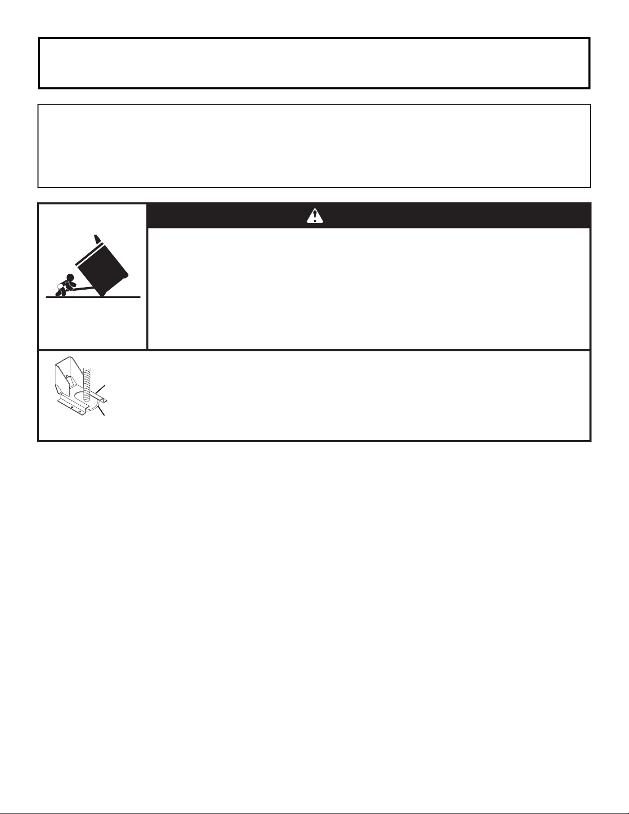
WARNING
Tip Over Hazard
A child or adult can tip the range and be killed.
Install anti-tip bracket to floor or wall per installation instructions.
Slide range back so rear range foot is engaged in the slot of the anti-tip bracket.
Re-engage the anti-tip bracket if the range is moved.
Do not operate range without anti-tip bracket installed and engaged.
Failure to follow these instructions can result in death or serious burns to children and adults.
Anti-Tip
Bracket
Range Foot
To verify the anti-tip bracket is installed and engaged:
• Slide range forward.
• Look for the anti-tip bracket securely attached to floor or wall.
Slide range back so rear range foot is under anti-tip bracket.•
• See installation instructions for details.
3
INSTALLATION REQUIREMENTS
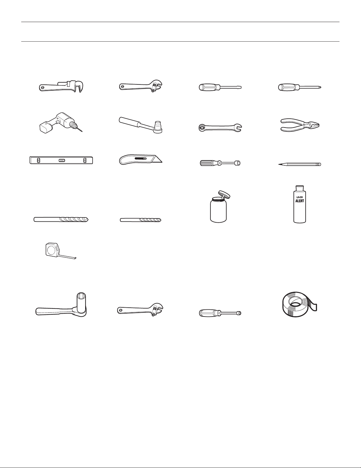
Tools and Parts
Gather the required tools and parts before starting installation. Read and follow the instructions provided with any tools listed here.
Tools Needed
Pipe wrench Adjustable wrench or
Drill 3/8" (95 mm) drive ratchet 15/16" (24 mm)
Level Tubing cutter 1/4" (6.4 mm), 3/8" (9.5 mm),
3/16" (4.8 mm) carbide tip
masonry bit
Tape measure
5/8" (16 mm) wrench
1/8" (3.2 mm) drill bit Pipe‑joint compound
1/8" x 41/4" (3 mm x 100 mm)
flat‑blade screwdriver
combination wrench
5/16" (7.9 mm) nut drivers
resistant to Propane gas
#2 Phillips screwdriver
Pliers
Marker or pencil
Noncorrosive leak‑detection
solution
For Propane/Natural Gas Conversions
1/2" (13 mm) deep‑well
socket
4
Adjustable wrench 1/4” (7 mm) nut driver Masking tape

Parts Supplied
B
Check that all parts are included.
■ Anti-tip bracket kit
A
A. Anti-tip bracket
B. #8-18 x 1" (2.5 cm) Phillips head screws (4)
NOTE: Anti-tip bracket must be securely mounted to
subfloor. Thickness of flooring may require longer screws
to anchor bracket to subfloor. Longer screws are available
from your local hardware store. See the “Install Anti-Tip
Bracket” section.
■ Gas pressure regulator
■ Burner grates
■ Burner bases and burner caps
■ Griddle drip tray (on griddle models)
■ Propane orifice package (W10393255)
■ Conversion label (W10839411)
NOTE: The range is manufactured for use with Natural gas. To
convert to Propane gas, see the “Gas Conversions” section.
Parts Needed
■ Power supply cord kit:
■ 30" (76.2 cm) and 36" (91.4 cm) models: A UL Listed
40-amp power supply cord kit
■ 48" (121.9 cm) models: A UL Listed 50-amp power
supply cord kit marked for use with nominal 13/8"
(3.5 cm) diameter connection openings
■ A UL Listed strain relief
■ UL Listed wire connectors
■ All models must be installed with a backguard if installing
at zero clearance to a combustible back wall surface such
as drywall. Alternatively, zero clearance to a back wall is
acceptable provided the surface of the entire back wall
above the range and below the hood is covered with a
non-combustible material such as tile or stainless steel.
See “Cabinet Dimensions” in the “Location Requirements”
section for installation requirements.
■ 30" (76.2 cm) Adjustable Backguard
Order Part Number 8285148
■ 36" (91.4 cm) Adjustable Backguard
Order Part Number 8284756
■ 48" (121.9 cm) Adjustable Backguard
Order Part Number 8284755
■ 22" (55.9 cm) Backsplash with Dual-Position Shelf
for 30" (76.2 cm) Ranges
Order Part Number W10285447
■ 22" (55.9 cm) Backsplash with Dual-Position Shelf
for 36" (91.4 cm) Ranges
Order Part Number W10285448
■ 22" (55.9 cm) Backsplash with Dual-Position Shelf
for 48" (121.9 cm) Ranges
Order Part Number W10285449
To order, see the “Assistance or Service” section of the
Use and Care Guide.
Check local codes and consult gas supplier. Check existing gas
supply and electrical supply. See the “Electrical Requirements”
and “Gas Supply Requirements” sections.
It is recommended that all electrical connections be made by
a licensed, qualified electrical installer.
High Altitude Conversion
To convert the cooktop for elevations above 6,560 ft (1,999.5 m),
order a High Altitude Conversion Kit.
■ Part Number W10394296: Propane gas high altitude
■ Part Number W10394295: Natural gas high altitude
To order, see the “Assistance or Service” section of the Use
and Care Guide.
5
Location Requirements
C
E
A
C
E
IMPORTANT: Observe all governing codes and ordinances.
Do not obstruct flow of combustion and ventilation air.
■ It is the installer’s responsibility to comply with installation
clearances specified on the model/serial/rating plate. The
model/serial/rating plate is located under the console on
the right-hand side.
■ It is recommended that a 600 CFM (17.0 m
range hood be installed above the range.
■ It is not recommended that a microwave hood combination
be mounted above the range.
■ Recessed installations must provide complete enclosure
of the sides and rear of the range.
■ All openings in the wall or floor where range is to be installed
must be sealed.
■ Do not seal the range to the side cabinets.
■ Cabinet opening dimensions that are shown must be used.
Given dimensions are minimum clearances.
■ The anti-tip bracket must be installed. To install the anti-tip
bracket shipped with the range, see the “Install Anti-Tip
Bracket” section.
■ Grounded electrical supply is required. See the “Electrical
Requirements” section.
■ Proper gas supply connection must be available. See the
“Gas Supply Requirements” section.
■ Contact a qualified floor covering installer to check that the
floor covering can withstand at least 200°F (93°C). Use an
insulated pad or 1/4" (6.4 mm) plywood over carpet and
under range if installing range over carpeting.
IMPORTANT: To avoid damage to your cabinets, check with
your builder or cabinet supplier to make sure that the materials
used will not discolor, delaminate, or sustain other damage. This
oven has been designed in accordance with the requirements
of UL and CSA International and complies with the maximum
allowable wood cabinet temperatures of 194°F (90°C).
3
/hr) or larger
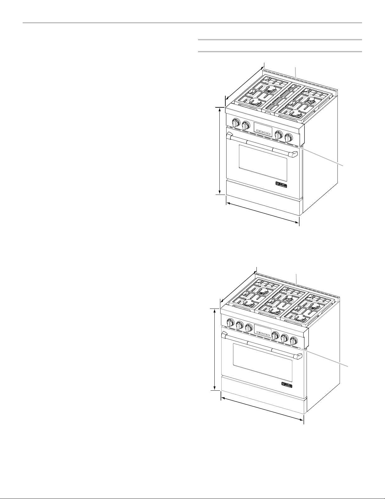
Product Dimensions
30" (76.2 cm) models
B
D
A. Island trim
3
B. 27
/4" (70.5 cm) depth with control panel (See NOTE.)
3
C. 35
/4" (90.8 cm) cooktop height when sitting on the wheels
D. 30" (76.2 cm) width
E. Model/serial/rating plate location
36" (91.4 cm) models
A
Mobile Home ‑ Additional Installation Requirements
The installation of this range must conform to the Manufactured
B
Home Construction and Safety Standard, Title 24 CFR,
Part 3280 (formerly the Federal Standard for Mobile Home
Construction and Safety, Title 24, HUD Part 280). When such
standard is not applicable, use the Standard for Manufactured
Home Installations, ANSI A225.1/NFPA 501A or local codes.
In Canada, the installation of this range must conform with
the current standards CAN/CSA-A240-latest edition or with
local codes.
Mobile Home Installations Require:
■ When this range is installed in a mobile home, it must be
secured to the floor during transit. Any method of securing
the range is adequate as long as it conforms to the
standards listed above.
D
A. Island trim
1
B. 27
⁄8" (68.9 cm) depth with control panel (See NOTE.)
3
C. 35
⁄4" (90.8 cm) cooktop height when sitting on the wheels
D. 36" (91.4 cm) width
E. Model/serial/rating plate location
6
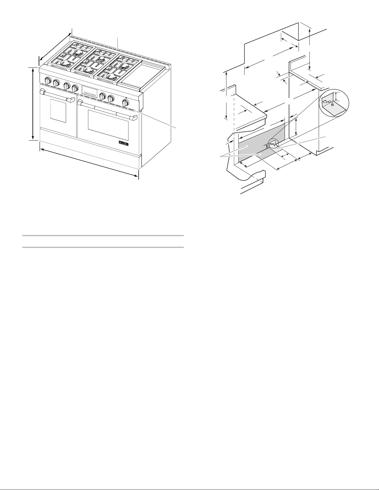
48" (121.9 cm) models
C
E
Electrical
installation
area*
installation
B
A
C
**
D
B
O***
A
E
F
J
F
I
H
I
G
Gas
area
J
L
D
A. Island trim
1
B. 27
⁄8" (68.9 cm) depth with control panel (See NOTE.)
3
C. 35
⁄4" (90.8 cm) cooktop height when sitting on the wheels
D. 48" (121.9 cm) width
E. Model/serial/rating plate location
NOTE: When installed in a 24" (61.0 cm) base cabinet with 25"
(63.5 cm) countertop; front of oven door protrudes 17/8" (4.8 cm)
beyond 24" (61.0 cm) base cabinet.
Cabinet Requirements
Cabinet opening dimensions shown are for 25" (64.0 cm)
countertop depth, 24" (61.0 cm) base cabinet depth, and
36" (91.4 cm) countertop height. Dimensions must be met
in order to ensure a flush fit to back wall.
IMPORTANT: If installing a range hood or hood liner above
the range, follow the range hood or hood liner installation
instructions for dimensional clearances above the
cooktop surface.
K
A. 18" (45.7 cm) upper cabinet to countertop
B. 30" (76.2 cm) model: 30" (76.2 cm) min. upper cabinet width
36" (91.4 cm) model: 36" (91.4 cm) min. upper cabinet width
48" (121.9 cm) model: 48" (121.9 cm) min. upper cabinet width
C. 13" (33 cm) max. upper cabinet depth
D. For minimum clearance to top of range.**
1
E. 30
/4" (76.8 cm) on 30" (76.2 cm) models
361/4" (92.1 cm) on 36" (91.4 cm) models
481/4" (122.6 cm) on 48" (121.9 cm) models
F. 6" (15.2 cm) min. clearance from both sides of range to side
wall or other combustible material
G. 15" (38.1 cm)
H. 22" (55.9 cm) on 30" (76.2 cm) models
28" (71.1 cm) on 36" (91.4 cm) models
40" (101.6 cm) on 48" (121.9 cm) models
1
I. 1
/2" (3.8 cm)
J. 3" (7.6 cm)
K. 5" (12.7 cm)
L. 6" (15.2 cm) on 30" (76.2 cm) models
14" (35.5 cm) on 36" (91.4 cm) models
24" (61.0 cm) on 48" (121.9 cm) models
1
M. 10
/2" (26.7 cm)
N. 6" (15.2 cm)
O. 6" (15.2 cm)***
N
M
* Receptacle must be rotated 90° for Canadian installation.
** Minimum Clearances
30" (76.2 cm) models: 30" (76.2 cm) minimum clearance
between the top of the cooking platform and the bottom of
an uncovered wood or metal cabinet
36" (91.4 cm) models: 42" (106.7 cm) minimum clearance
between the top of the cooking platform and the bottom of
an uncovered wood or metal cabinet
48" (121.9 cm) models: 42" (106.7 cm) minimum clearance
between the top of the cooking platform and the bottom of
an uncovered wood or metal cabinet
*** If the surface of the back wall is constructed of a combustible
material and a backguard is not installed, a 6" (15.2 cm)
minimum clearance is required for all models.
7
 Loading...