

Page 1

WWW.BEGLEC.COM
Operation Manual
Mode d'emploi
Gebruiksaanwijzing
Bedienungsanleitung
Manual de instrucciones
Manual do utilizador
EN
FR
NL
DU
ES
PT
Reproduction or publication of the content in any manner, without express permission of the publisher, is prohibited.
Copyright © 2007 by BEGLEC cva.
Version: 1.1
Page 2
EN - DISPOSAL OF THE DEVICE
Dispose of the unit and used batteries in an environment friendly manner
according to your country regulations.
FR - DÉCLASSER L’APPAREIL
Débarrassez-vous de l’appareil et des piles usagées de manière écologique
Conformément aux dispositions légales de votre pays.
NL - VERWIJDEREN VAN HET APPARAAT
Verwijder het toestel en de gebruikte batterijen op een milieuvriendelijke
manier conform de in uw land geldende voorschriften.
DU - ENTSORGUNG DES GERÄTS
Entsorgen Sie das Gerät und die Batterien auf umweltfreundliche Art und
Weise gemäß den Vorschriften Ihres Landes.
ES - DESHACERSE DEL APARATO
Reciclar el aparato y pilas usadas de forma ecologica conforme a las
disposiciones legales de su pais.
PT - COMO DESFAZER-SE DA UNIDADE
Tente reciclar a unidade e as pilhas usadas respeitando o ambiente e em
conformidade com as normas vigentes no seu país.
Page 3
ENGLISH OPERATION MANUAL
ENGLISH OPERATION MANUAL
Thank you forbuying this JB Systems®product. To take full advantage of all possibilities, please read these
operatinginstructionsverycarefully.
FEATURES
This unit is radio-interference suppressed. This appliance meets the requirements of the current European
and national guidelines. Conformity has been established and the relevant statements and documents have
been deposited by the manufacturer.
10-channel P.A. mixer
Suited for microphone mixing or smallbands
6 mono channels, 2 stereochannels
Balancedmic inputandline input on each channel
3-band tone controlon each channel
2 auxiliary outputs
Extra line input that can be directly injected to the master
48V Phantompowersupply
Balancedleft and right masteroutput
BEFORE USE
Beforeyou start using this unit, please check if there’s no transportation damage.Should there be any, do
not use the device and consult your dealerfirst.
Important: This device left our factory in perfect condition and well packaged. It is absolutely necessary
for the user to strictly follow the safety instructions and warnings in this user manual. Any damage caused
bymishandling is not subject to warranty. The dealer will not accept responsibility for any resulting defects
orproblems caused by disregarding this user manual.
Keep this booklet in a safe place for future consultation. If you sell the fixture, be sure to add this user
manual.
To protect theenvironment,please try to recyclethe packing material as much as possible.
Check the contents:
Check that the carton contains the following items:
User manual
MM-10 unit
Mainscable
SAFETY INSTRUCTIONS:
CAUTION: To reduce the risk of electric shock, do not remove
CAUTION
The lightning flash with arrowhead symbol within the equilateral triangle is intended to alertthe use
or the presenceof un-insulated “dangerous voltage” within the product’s enclosure that may be of
sufficientmagnitude to constitute a risk of electricshock.
the top cover. No user-serviceable parts inside. Refer
servicing to qualified service personnel only.
To prevent fire or shock hazard, do not expose this appliance to rain or moisture.
To avoid condensation to be formed inside, allow the unit to adapt to the surrounding temperatures when
This unit is for indoor use only.
Don’t placemetal objects or spill liquid inside the unit. No objectsfilled with liquids, such as vases, shall be
No naked flame sources,such as lighted candles, should be placed on the appliance.
Don’t cover any ventilation openings as this may result in overheating.
Preventuse in dusty environmentsand clean the unit regularly.
Keep the unit away from children.
Inexperienced persons should not operatethis device.
Maximumsave ambient temperature is 40°C. Don’t use this unitat higher ambient temperatures.
Alwaysunplug the unit when it is not used fora longer time or beforeyou start servicing.
The electricalinstallation should be carried out by qualified personal only, according to the regulations for
Check that the available voltageis not higher than the one statedon the rear panel of the unit.
The socket inlet shall remain operablefordisconnection from the mains.
The powercord should alwaysbe in perfectcondition: switch the unit immediatelyoff when the power cord
Never let the power-cord come into contact with other cables!
When the powerswitch is in OFF position, this unit is notcompletely disconnected from the mains!
This appliancemust be earthed to in order comply with safety regulations.
In order to prevent electric shock, do not open the cover. Apart from the mains fuse there are no user
Never repair a fuse or bypass the fuse holder. Always replace a damaged fuse with a fuse of the same
In the event of serious operating problems, stop using the appliance and contactyourdealer immediately.
Pleaseuse the original packing when the device is to be transported.
Due to safety reasonsit is prohibited to make unauthorized modifications to the unit.
INSTALLATION GUIDELINES:
Installthe unit in a well-ventilated location where it will not be exposedto high temperatures or humidity.
Placing and using the unit for long periods nearheat-generating sources such as amplifiers,spotlights, etc.
The unit can be mounted in 19-inch racks. Attach the unit using the 4 screw holes on the front panel. Be
When installed in a booth or flight case, please make sure to have good ventilation to improve heat
To avoid condensation to be formed inside, allow the unit to adapt to the surrounding temperatures when
CLEANING THEAPPLIANCE:
Clean by wiping with a polished cloth slightly dipped with water. Avoid getting water inside the unit. Do not
use volatile liquids such as benzene or thinner which will damage the unit.
This symbol means:Read instructions.
bringing it into a warm room after transport. Condense sometimes prevents the unit from working at full
performance or may even cause damages.
placed on this appliance. Electric shock or malfunction may result. If a foreign object enters the unit,
immediately disconnectthe mains power.
electricaland mechanical safety in your country.
is squashedor damaged.
serviceablepartsinside.
type and electrical specifications!
will affect its performance and may even damage the unit.
sure to use screws of the appropriate size. (screws not provided)
Takecare to minimize shocks and vibrations during transport.
evacuationof the unit.
bringing it into a warm room after transport. Condense sometimes prevents the unit from working at full
performance.
The exclamation point within the equilateral triangle is intended to alert the user to the presence of
important operation and maintenance (servicing) instructions in the literature accompanying this
appliance.
Thissymbol means: indoor use only.
JB SYSTEMS® 1/41 MM-10
CONNECTIONS
For more information on connections, please referto the next chapter.
Be sure to turn off the mixer before you make changes to the different connections.
In this manual we talk about “line inputs”. This is a global namefor inputs with a level between 750mV and
2V.This includes tuners, videos, CD-players, etc.
JB SYSTEMS® 2/41 MM-10
Page 4
ENGLISH OPERATION MANUAL
ENGLISH OPERATION MANUAL
FUNCTIONS
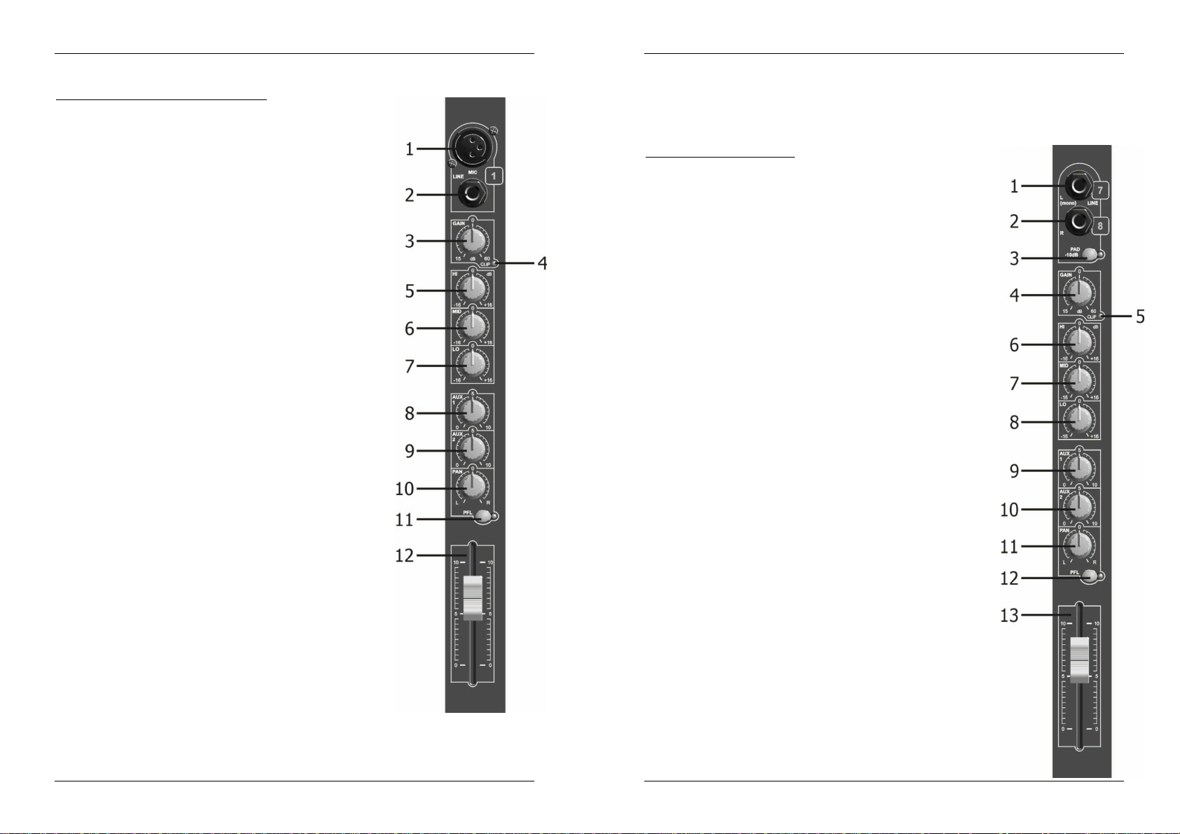
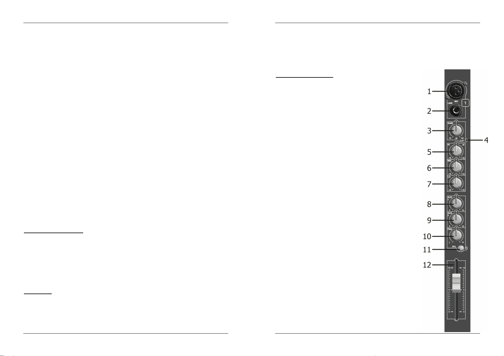
MONO MICROPHONE/LINEINPUT CHANNEL
1. 3 PIN FEMALE XLR SOCKET INPUT
Balancedinputwiring: Pin 1 = Ground (sleeve)
Unbalancedinputwiring: Pin 1 = Ground
Inputimpedance: 2k Ohm
Input sensitivity: 0.8mV RMS (-60dB)
2. 1/4" STEREO JACK SOCKET INPUT
Balancedinputwiring:
Tip = Positive signal
Ring = Negativesignal
Sleeve= Ground
Unbalancedinputwiring:
Tip = Signal
Ring = Ground
Sleeve= Ground
(Mono jack plug will automatically give this)
Input impedance: >50K Ohm
Input sensitivity: 25mV RMS (-30dB)
3. GAIN CONTROL
Allowsmaximum input signal control and will accommodate most
microphones of both low or high impedanceto 600 Ohm as well as
Phantom Power (48 Volt)types. The line input can beanything
from keyboard through toline level feeds from other equipment.
Gain range:
XLR input +15 to+60dB
Jackinput –15to +30dB
4. CLIP LED
This warning will illuminate4dB beforeclipping and will remain on
for a short period. For optimalinput channel running level, adjust
Gain Control until Clip indicatorilluminates while signalpeaksare
present.Then
adjust the gain setting until Clip indicator is off. This will give
optimalsignal to noise.
5. EQ CONTROL ‘HIGH’
This control allows 16dB of cut orboost to the high frequencies.
6. EQ CONTROL ‘MID’
This control allows 16dB of cut or boost to the mid frequencies.
7. EQ CONTROL ‘LOW’
This control allows 16dB of cut or boost to the low frequencies.
8. AUXSEND 1
This auxiliary send controlis ‘Post-fade’ and can be used to control
themixof inputs being processed by effects, etc. Its level will
change with thechannel fader(12).
9. AUXSEND 2
This auxiliary send controlis ‘Pre-fade’and can be used to control
the mix of inputs to an independent output such as monitoring. Its
levelwill notchange with channel fader (12).
Note:the Post-Fade option can only be selected by your service engineer.
10. PAN CONTROL
This control is used toset the stereobalance of the input signal and can ‘Pan’ it fully to the left or
right.
Pin 2 = Positive signal
Pin 3 = Negative signal
Pin 2 = Signal
Pin 3 = Ground
11. PFL SWITCH
This switch and indicatorallows pre-fade listen of input signals through the headphone and Led
meters(useful whilesetting gains or trouble shooting).
12. 60mmFADER
This slide control provides level control of input signal to the main stereo mix output and will also
control the Post-FadeAux Send 1.
STEREOLINEINPUTCHANNEL
1. LINE INPUT LEFT OR MONO – 1/4" MonoJack Socket
If the input is connected to a mono source use this connection
only as the signal will automatically be routed to the right input also.
Inputwiring:
Tip = Signal Sleeve = Ground
Inputimpedance: 10K Ohm
Input sensitivity: 24.5mV (-30dBm)
2. LINE INPUT RIGHT – 1/4" MonoJacket Socket
Inputwiring:
Tip = Signal Sleeve = Ground
Inputimpedance: 10K Ohm
Inputsensitivity: 24.5mV (-30dBm)
3. PADSWITCH
Operationof this switch reduces the input sensitivityby 10Db allowing
it to be used with high output devices such as CD playersas well as
musicalinstruments.
4. GAIN CONTROL
The panel marking at 0dB is a true reference to 0dBm when the –10dB
Pad is engaged.
Range:+10dB
5. CLIP LED
This warning light will illuminate 4dB beforeclipping and will remain on
fora short period. For optimal inputchannel running level,adjust Gain
Control until Clip indicator illuminateswhile signal peaksare present.
Then adjust the gain setting untilClip indicatoris off.This will give
optimalsignal to noise.
Note:IfEQ controls are altered this Gain/Clip setting will need
adjustment.
6. EQ CONTROL ‘HIGH’
This control allows 16dB of cut or boost to the high frequency content
of the input signal.
7. EQ CONTROL ‘MID’
This control allows 6dB of cut or boost to the mid frequencies.
8. EQ CONTROL ‘LOW’
This control allows 6dB of cut or boost to thelow frequencies.
9. AUXSEND 1
This auxiliary send control is ‘Post-fade’ and can be used to control the
mix of inputs being processed by effects, etc.
Itslevel will change with the input fader (13).
10. AUX SEND 2
This auxiliary send controlis ‘Pre-fade’and can be used to control the
mixof inputs to an independent output such as monitoring. Itslevel will
NOT change with input fader.
Note: The Post-fade option can only be selected byyour service
engineer.
11. BALANCE CONTROL
This control is used to set the stereo balance of the input signal and
can pan it fully to the left or right.
12. PFL SWITCH
This switch and indicatorallows pre-fade listen of input signals through
the headphone and Led meters(useful while setting gains or trouble
shooting).
JB SYSTEMS® 3/41 MM-10
JB SYSTEMS® 4/41 MM-10
Page 5
ENGLISH OPERATION MANUAL
ENGLISH OPERATION MANUAL
13. 60mmFADER
This Slide control provides levelcontrol of input signal to the main stereo mix output and will also
control the Post-fadeAux Send 1.
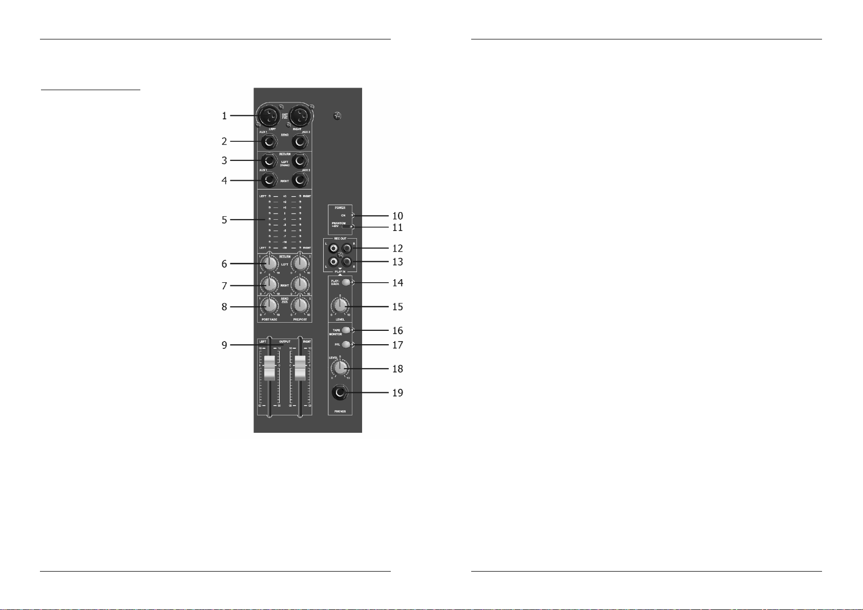
STEREOOUTPUT CHANNEL
1. STEREO OUTPUT - 3 pin Male XLR Socket
Output wiring:
Balanced: Unbalanced:
Pin 1= Ground Pin 1 = Ground
Pin 2 = Positive Signal Pin 2 = Signal
Pin 3 = NegativeSignal Pin 3 = no
Nominal Output Level:
Balanced+6dBm (1.55V RMS variableto
+10/16dB)
Unbalanced 0dBm (0.775V RMSvariable
to+10/16dB)
Impedance:
Output: <50 Ohm MinimumLoad: 600
Ohm
2. AUX SEND OUTPUT – 1/4" Jack Mono
Socket (unbalanced) output
Output wiring:
Tip = Signal Sleeve= Ground
Nominal Output Level:
0dBm (0.775VRMSvariableto +10dBm)
Impedance:
Output: <50 Ohm MinimumLoad: 5K Ohm
3. AUX RETURN LEFT/MONO – 1/4" Jack
Mono Socket Input
(If used as mono input it will automatically
connectthe input to theAUX Return Right
socket)
Output wiring:
Tip = Signal Sleeve= Ground
Inputimpedance: 10K Ohm
Input sensitivity:250mV RMS (-10DBm)
4. AUX RETURN RIGHT/MONO – 1/4" Jack
Mono Socket Input
Same as (3) Aux Return Left/Mono.
5. LED METER
This is a 10 segmentLed meterwith VUcalibration providing a signal monitor range from –20dB to
3dB with a change of colour at the nominal 0dB position.
6. AUX RETURN LEFT LEVEL CONTROL
This level controlwill set the desire amount of return signal on to themain left output mix only.
7. AUX RETURN RIGHTLEVEL CONTROL
This level control will set thedesired amount of return signal on to the main right output mix only.
(Usein conjunction with left level (6) when mixing a mono input signal)
8. MASTERAUX SEND OUTPUT LEVEL CONTROL
This level control sets the desired output level of Auxsend mix to the output socket (it’s best set at
N°7when Finitiallysetting up). Subsequently adjust tolevel required by externalequipment.
(sleeve)
connection
9. MASTEROUTPUT FADER CONTROL
This Slide control is used to set the required overalloutput level to the poweramplifier (or other
equipment).The calibrationshows a suggested nominal running level,referenced ‘0’ (10dB boostis
availableif required).
10. ON INDICATOR
This ledindicates that the mixer power is on.
11. PHANTOMSWITCH
This switch is recessedto prevent accidental operation and has a corresponding red LED indicator; it
shouldNOT be operated while the mixeris live.
NOTE:
Itshould be pre-selected during setting up with the main output faders and MIC input gain
controlsdown.
ALL XLR MIC inputs will be phantom powered when selected. Some microphones that do NOT
require phantom supply may not operate or are damaged – checkinstructions.
The Jack Line inputs will be unaffected and can be used as normal.
12. STEREO RECORD OUTPUT – Left and RightRCA Socket Outputs (unbalanced)
13. STEREO PLAYBACK INPUT – Left and Right RCA Socket Inputs (unbalanced)
14. PLAYBACK SWITCH
15. PLAYBACK LEVEL CONTROL
16. TAPE MONITOR SWITCH
17. PFL SWITCH
18. HEADPHONE LEVEL CONTROL
19. HEADPHONE OUTPUT– 1/4" Stereo Jack SocketOutput
(Your service station may be able to disable the Phantom Power)
The signal is derived from the main stereo output mix after the output faders.
Nominal‘0’ Output Level: -10dBv(316mVRMS)
Output impedance:600 Ohm
Load impedance (min): 5K Ohm
Signal is routed to the main stereo output beforethe faders and the monitoring system.
Normal Input Sensitivity:316mV RMS (-10dBv)
Input impedance: 5K Ohm
AllowsON/OFF control of Playbackinput signal onto the main stereo output mix.
Levelcontrol of the 2-tracktape playbackonto the main stereo output of the mixer (before the main
outputfaders) set for desired mix.
This switch sets the Headphone and Led MeterMonitoringsystem over to TapePlayback monitoring
(Before the playbackswitch and levelcontrol).
This switch sets the Headphone and Led Meters system over to PFL(input pre-fadelisten)
monitoring. It works in conjunction with PFL switches on each input channel.
This control is used in conjunction withthe switch to monitor signals within the mixer. With both Tape
Monitorand PFL switches ‘OFF’ the headphonesystem and Led meters will monitor the main stereo
output.
Output wiring:
Tip = left signal
Ring = right signal
Sleeve= ground
Minimum Load impedance: 40 Ohm
JB SYSTEMS® 5/41 MM-10
JB SYSTEMS® 6/41 MM-10
Page 6
ENGLISH OPERATION MANUAL
SPECIFICATIONS
Power Supply: AC230 V, 50Hz
Fuse: 1A/250V
Frequencyresponse: 15-20.000Hz
THD + noise: <0.01% @ 1kHz, 0dB
S/N Ratio (IHF-A): >80dB
Micro inputs: 200-600Ohm/balanced
Line inputs: 300mV @ 10kΩ
Record output: 775mV @ 50kΩ
Master output: 775mV @ 600Ω
Tonecontrols: +/-16dB @ 10kHz / 600Hz / 60Hz
Dimensions: 483(W) x 360(H) x 80(D) mm
Weight: 7.8kg
You can downloadthe latest version of thisuser manual on our website: www.beglec.com
Every informationis subject to change withoutprior notice
FRANCAIS MODE D’EMPLOI
Nous vous remercions d’avoir acheté ce produit JB Systems®. Veuillez lire ce mode d’emploi très
attentivement afin de pouvoir exploitertoutesles possibilités de cet appareil.
CARACTERISTIQUES
Cet appareil ne produit pas d’interférences radio. Il répond aux exigences nationales et européennes. La
conformité aété établie et les déclarationset documentscorrespondants ont été déposés par le fabricant.
Table de mixage P.A.
Pour mixagedes micros et des petits groups
6 canaux Mono,2 canauxStéréo
Entrée balancée micro et ligne pour chaque canal
Réglage de tonalité à 3 bandes
2 sorties auxiliaires
Entrée cassette,dirigée vers la sortie master
Alimentation “Phantom” de 48V
Sortie balancée (gauche et droite)
AVANT L’UTILISATION
Quelquesinstructionsimportantes:
Avant d’utiliser cet appareil, assurez-vous de l’absence de dommage lié au transport. En cas
d’endommagement,n’utilisezpas l’appareil et contactez le vendeur.
Important:
l’utilisateur suive les instructions de sécurité et avertissements inclus dans ce manuel. La garantie ne
s’applique pas en cas de dommage lié à une utilisation incorrecte. Le vendeur ne prend pas la
responsabilité des défauts ou de tout problème résultant du fait de n’avoir pas tenu compte des mises en
garde de ce manuel.
Conservez ce manuel dans un endroit sûr pour toute consultation future. Si vous vendez l’appareil,
assurez-vous d’y joindre ce manuel également.
Afinde protéger l’environnement,mercide recycler les emballages autant que possible.
Vérifiez le contenu:
Vérifiezsi la boite contient les articles suivants :
Moded’emploi
MM-10
Câble secteur.
Cet appareil a quitté notre usine en parfaite condition et bien emballé. Il est primordial que
JB SYSTEMS® 7/41 MM-10
INSTRUCTIONS DE SECURITE:
ATTENTION: afin de réduire le risque d’électrocution,
CAUTION
qualifiés.
La flèche dans un triangle met l'utilisateur en garde contre la présence de haute tension sans
isolationdans l'appareilqui peut causerun risque d'électrocution.
Un point d'exclamation dans un triangle prévient de la présence d'instructions de fonctionnement
et de maintenance se trouvant dans le manuel, fourni avec l'appareil.
Ce symbole signifie : uniquement pour usageà l'intérieur
Afin d’éviter tout risque d’incendie ou de choc électrique, ne pas exposer cet appareil à la pluie ou
Ce symbole signifie : Lire le mode d’emploi.
l’humidité.
JB SYSTEMS® 8/41 MM-10
n’enlevez jamais le couvercle de l’appareil. Il n’y a aucune
pièce à l’intérieur de l’appareil que vous pouvez remplacer
vous-même. Confiez l’entretien uniquement à des techniciens
Page 7
FRANCAIS MODE D’EMPLOI
FRANCAIS MODE D’EMPLOI
Pour éviter la formation de condensation à l’intérieur de l’appareil, patientezquelques minutes pour laisser
l’appareil s’adapter à la température ambiante lorsqu’il arrive dans une pièce chauffée après le transport.
La condensation empêche l’unité de fonctionner en performance optimale et peut même causer des
dommages.
Cetteunité est destinée à une utilisationà l’intérieur uniquement.
Ne pas insérer d’objet métallique ou verser un liquide dans l’appareil. Aucun objetrempli de liquides, tels
que des vases, ne peut être placé sur cet appareil. Risquede choc électrique ou de dysfonctionnement. Si
un corps étranger est introduitdans l’unité,déconnectezimmédiatement de la sourced’alimentation.
Aucune source de flamme nue, telleque les bougies allumées, ne peut être placée sur l'appareil.
Ne pas couvrir les ouverturesde ventilation, un risque de surchauffe en résulterait.
Ne pas utiliser dans un environnement poussiéreuxetnettoyez l’unitérégulièrement.
Ne pas laisserl’unité à portéedes enfants.
Les personnes non expérimentées ne doivent pas utiliser cet appareil.
La température ambiante maximum d’utilisation de l’appareil est de 40°C. Ne pas l’utiliser au-delà de cette
température.
Débranchez toujours l’appareil si vous ne l’utilisez pas de manière prolongée ou avant d’entreprendre des
réparations.
Les installations électriques ne peuvent être faites que par du personnel qualifié et conformément aux
régulationsde sécurité électriqueet mécanique en vigueur dans votre pays.
Assurez-vous que la tension d’alimentation de la source d’alimentationde la zone dans laquelle vous vous
trouvezne dépassepas celui indiqué à l’arrière de l’appareil.
La prise seratoujours accessible pour que le cordon secteur puisse être enlevé à chaque moment.
Le cordon d’alimentationdoit toujours êtreen condition parfaite. Mettezimmédiatementl’unité hors tension
si le cordon est écrasé ou endommagé.
Ne laissez jamais le cordon d’alimentation entrer en contactavec d’autres câbles !
Quand l’interrupteur principal est dans la position OFF, cet appareil n'est pas complètement isolé du
courant230V!
L’appareil doit être à la masse selon les règles de sécurités.
Utiliseztoujours les câbles appropriés et certifiés lorsque vous installezl’unité.
Pour éviter tout choc électrique, ne pas ouvrir l’appareil. En dehors du fusible principal, il n’y a pas de
pièces pouvant être changées par l’utilisateur à l’intérieur.
Nejamais réparer ou court-circuiterun fusible. Remplacez systématiquement un fusible endommagé par
un fusible et de mêmestype et spécifications électriques !
En cas de problèmes de fonctionnement sérieux, arrêtez toute utilisation de l’appareil et contactez votre
revendeurimmédiatement.
Utilisezl’emballaged’origine si l’appareil doit êtretransporté.
Pour des raisons de sécurité, il est interdit d’apporter toute modification à l’unité non spécifiquement
autoriséepar les parties responsables.
CONSEILS D'INSTALLATION:
Installer l'appareildans un lieu bien aéré, à l'abride l'humidité et des fortes températures.
Placer et utiliser l'appareil à proximité de sources de chaleur telles que spots, amplis,… pourrait affecter
ses performances et même endommager l'appareil.
L'appareil peut être installé dans un rack 19''. Fixer l'appareil en utilisant les 4 trous pour vis sur la face
avant. Assurez-vous d'utiliser des vis de la bonne dimension (vis non fournies). Essayez d'éviter les
vibrations et les coups lors du transport.
En cas d'installation dans un 'flight case', assurer une bonne ventilation afin d'évacuer la chaleur produite
par l'appareil.
Pour éviter la condensation à l'intérieur, laisser l'appareil s'adapter à la nouvelle température ambiante
après le transport. La condensation peut altérer les performances de l'appareil.
NETTOYAGE:
Nettoyezl’appareil à l’aide d’un chiffon doux, légèrement humide. Evitez d’introduire de l’eau à l’intérieur de
l’appareil. N’utilisez pas de produits volatiles tels que le benzène ou le thinner qui peuvent endommager
l’appareil.
CONNEXIONS
Pour plus d'informationssur les connections, voyez le chapitresuivant.
Assurez-vous d'éteindre la table de mixage avant d'effectuer les différentes connections. Dans ce mode
d'emploi,il est question d'entrée ligne ou “line inputs”. Il s'agit en faitd'un terme générique pour désigner des
entrées avecun niveaucompris entre 750mV et 2V.Ceciinclus les lecteurs de CD, tuners, vidéos,…
FONCTIONS
ENTREE MONOMICRO/LINE
1. ENTRÉE FEMELE XLR POUR MICROPHONE
Mode balancé:
Pin 1 = Masse
Pin 2 = Positif
Pin 3 = Négatif
Modenon-balancé:Pin 1 = Masse
Pin 2 = Pointchaud
Pin 3 = Masse
Impédance d’entrée:2K Ohm
Sensibilitéd’entrée: 0.8 mV RMS (-60dB)
2. ENTRÉE LIGNE STEREO 1/4’’
Mode balancé: Pointe = Positif
Anneau= Négatif
Châssis = Masse
Modenon-balancé: Pointe = Positif
Anneau = Masse
Châssis = Masse
(Une fiche jack mono donneautomatiquement ceci)
Impédance d’entrée:>50K Ohm
Sensibilité d’entrée : 25 mV RMS (-30dB)
3. RÉGLAGE DE GAIN
Permetun réglage d’entrée maximalet convient à la plupart des
micros avec une impédance jusqu’à 600 Ohm comme ceux de type
Phantom Power (48 Volt).
Gain Range: Entrée XLR +15 à +60dB
Entrée Jack –15 à +30db
4. CLIPPEAK LED (INDICATEURDE NIVEAU MAXIMUM)
L’indicateurd’écrêtages’allume4dB avant le signal maximumet
resteraallumé pendant une courte période.
NB : si le réglage de tonalité(cf.point 5,6,7) est modifié,le réglage
du Gaindoit être ajusté.
5. CONTRÔLE(EQ) DE TONALITÉ HIGH (AIGUES)
Ce réglagepermetun réglage allant de -16dB à 16dB pourdes
fréquencesaiguës.
6. CONTRÔLE(EQ) DE TONALITÉ MID (MOYENNES)
Ce réglagepermetun réglage allant de -16dB à 16dB pourdes
fréquencesmoyennes.
7. CONTRÔLE(EQ) DE TONALITÉ LO (BASSES)
Ce réglagepermetun réglage allant de -16dB à16dB pour des
fréquencesbasses.
8. CONTRÔLEAUX (Envoi 1)
Ce réglage d’auxiliaire est (Post-fade) et peut être utilisé pour
contrôlerdes sources extérieures indépendantescomme le
monitoring. Piloté par le fader d’entrée (12).
JB SYSTEMS® 9/41 MM-10
JB SYSTEMS® 10/41 MM-10
Page 8

FRANCAIS MODE D’EMPLOI
FRANCAIS MODE D’EMPLOI
9. CONTRÔLEAUX (Envoi 2)
Ce réglage d’auxiliaire est (Pre-fade) et peut être utilisé pour contrôler des sources extérieures
indépendantes comme le monitoring. NONpiloté par le fader d’entrée(12).
NB : l’option Post-Fade peut uniquement êtresélectionnée par un servicetechnique compétent.
10. CONTRÔLE PAN
Permetd’effectuer la balance panoramiquedu signal stéréo d’un côté à l’autre.
11. PREECOUTE(PFL)
Touche + LED permet l’écoutepre-fadedu signal d’entrée dans les écouteurs et sur les Led meters
(utilependant le réglage de gain ou trouble-shooting).
12. CURSEUR RECTILIGNEDE 60mm
Ce curseur permet d’envoyer le signal d’entrée mixé vers la sortie et
règle galement le contrôle Post-Fade AUX Envoi 1.
ENTREE STEREO LINE
1. ENTRÉE LIGNE GAUCHE OU MONO – JACK MONO1/4’’
Si l’entrée est requise pour une source mono, utiliser cette connexion de
manièreà ce que le signal soit automatiquement transmis à l’entrée
droite.
Pointe: Positif Châssis:Masse
Impédance d’entrée:10K Ohm
Sensibilitéd’entrée: 24.5mV (-30dBm)
2. ENTRÉE LIGNE DROITE OU MONO – JACK MONO 1/4’’
Pointe: Positif Châssis:Masse
Impédance d’entrée:10K Ohm
Sensibilitéd’entrée: 24.5mV (-30dBm)
3. PAD
Ce bouton enfoncé, le signal est atténué de -10dB ce qui permet d’utiliser
des appareils avec signal de sortie élevé commeles lecteursCD et
instruments de musique.
4. RÉGLAGE DE GAIN
Le panneau de marquage à 0dB estune vraie référenceà 0dBm quand
le Pad -10 dB est enclenché.
5. CLIP LED
L’indicateur d’écrêtages’allume 4dB avant le signal maximumet restera
allumé pendant une courte période.
NB : si le réglage de tonalité (cf. point6,7,8)estmodifié, le réglage du
Gain doit être ajusté.
6. CONTRÔLE(EQ) DE TONALITÉ HIGH (AIGUES)
Ce réglagepermetun réglage allant de -16dB à 16dB pourdes
fréquencesaiguës.
7. CONTRÔLE(EQ) DE TONALITÉ MID (MOYENNES)
Ceréglage permetun réglage allant de -16dB à 16dB pourdes
fréquencesmoyennes.
8. CONTRÔLE(EQ) DE TONALITÉ LO (BASSES)
Ce réglagepermetun réglage allant de -16dB à 16dB pourdes
fréquencesbasses.
9. CONTRÔLEAUX (ENVOI 1)
Ce réglage d’auxiliaire est (Post-fade) et peut être utilisé pour contrôler
des sources extérieuresindépendantescommele monitoring. Piloté par
le fader d’entrée (13).
10. CONTRÔLEAUX (ENVOI 2)
Ce réglage d’auxiliaire est (Pré-fade) et peut être utilisé pour contrôler
des sources extérieuresindépendantes comme le monitoring. NON piloté
par le fader d’entrée.
NB : l’option Post-Fade peut uniquement être sélectionnée par unservice
techniquecompétent.
11. CONTRÔLEPAN
Permetd’effectuer la balance du signal stéréo d’un côté à l’autre.
12. PREECOUTE(PFL)
Touche+ LED permet l’écoute pre-fade du signal d’entrée dans les écouteurs et sur les Led meters
(utilependant le réglage de gain ou trouble-shooting).
13. CURSEUR RECTILIGNEDE 60MM
Ce curseur permet d’envoyer le signal d’entrée mixé vers la sortie et règle également le contrôle
Post-Fade AUX Envoi 1.
SORTIE STEREO
1. SORTIESTEREO MALE XLR
Modebalancé:
Pin 1 = Masse
Pin 2 = Positif
Pin 3 = Négatif
Modenon-balancé:
Pin 1 = Masse
Pin 2 = Positif
Pin 3 = Pas de connexion
Niveau de sortie nominal:
balancé+6dBm (1.55V RMS variable à
+10/16dB)
Non-balancé0dBm(0.775V RMS
variableà +10/16dB)
Impédance:Sortie<50Ohm
2. 2. SORTIE AUX – 1/4’’ JACK MONO (NONBALANCÉ)
Sortie:
Pointe = Positif Châssis =Masse
Niveau de sortie nominal: 0dBm (0.775V
RMS (variable à +10dBm)
Impédance:Sortie<50Ohm
3. RETOURAUX GAUCHE – 1/4’’JACK
MONO ENTRÉE
(Si utilise entrée mono, connexion
automatiqueà l’entrée AUXRETURN
DROITE).
Sortie:
Pointe = Positif Châssis =Masse
Impédance d’entrée:10k Ohm
Sensibilitéd’entrée: 250 mV RMS (10dBm)
4. RETOURAUX DROIT/MONO – 1/4’’JACK
MONO ENTRÉE
Sortie:
Pointe = Positif Châssis = Masse
Impédance d’entrée:10k Ohm
Sensibilitéd’entrée: 250 mV RMS (-10dBm)
5. LED METER
Led meter composé de 10 voyants lumineuxavec calibrage Vu fournissant un moniteur signal
compris entre -20dB et 3dB avecun changementde couleur à la position nominale de 0dB.
6. RÉGLAGEDURETOURAUX GAUCHE
Permetde régler laquantité désirée du signalde retour dans la sortie gauche uniquement.
JB SYSTEMS® 11/41 MM-10
JB SYSTEMS® 12/41 MM-10
Page 9

FRANCAIS MODE D’EMPLOI
7. RÉGLAGEDURETOUR AUX DROIT
Permetde régler la quantité désirée de signal de retourdans la sortie droite uniquement.(A utiliser
en combinaison avec le niveau gauche (6) quand vous mixez un signal d’entrée mono)
8. MASTER: CONTRÔLE DU NIVEAU DE SORTIE AUX
Règle le niveau de sortie AUX Send. (Ilest préférable de régler le niveau initialement à l’aide du
n°7).
9. MASTER:CURSEUR DE CONTRÔLE DE SORTIE
Utiliserce curseur pour régler le niveaude sortie général de l’amplificateur (ou autre équipement).
Le marquage propose un niveau nominal suggéré,indiqué par '0' (un surplus de 10dB est disponible
sinécessaire).
10. LED ON
Indique que la table de mixage est allumée.
11. INTERRUPTEUR PHANTOM
Cet interrupteur est enfoncépour prévenir des opérations pouvant causer des dommages (il a son
Ledcorrespondant) : il ne faut EN AUCUN CAS l’utiliser quand la table est en fonctionnement.
12. SORTIE STÉRÉO RECORD - CONNECTEURSRCA(NON-BALANCÉS)
Le signal est pris en sortie finale après les curseurs.
Signal de sortie nominal: -10 dB (316mV-RMS)
Impédance de sortie: 600 Ohm
Impédance de chargemin.: 5 KOhm
13. ENTRÉE STÉRÉOPLAYBACK - CONNECTEURS RCA(NON-BALANCÉS)
Le signal est véhiculé vers la sortiestéréo à travers les curseurs etle circuit monitoring.
Sensibilitéd’entrée:316mV-RMS (-10dB)
Impédance d’entrée: 5 KOhm
14. INTERRUPTEURPLAYBACK
Permetla coupure ou non du signal d’entrée‘Tape’.
15. CONTRÔLEDU NIVEAU PLAYBACK
Contrôle le niveau du play-backà envoyer vers la sortiemixée à travers les curseurs principaux.
16. INTERRUPTEUR ‘TAPE MONITORING’
Permetle contrôle au casqueet display à Led’s du circuit ‘Tape Play-back’ (signal pris avant (14) et
(15)).
17. INTERRUPTEUR PFL
En combinaison avec celui de chaque canal,permetle contrôle du signal (Pre-Fade Listen) au
casqueet au barre graphe à Led’s.
18. CONTRÔLEDU NIVEAUCASQUE
Règle le niveau d’amplificationdu casque.
19. SORTIE CASQUE – JACK 1/4’’ STÉRÉO
Configuration:
Pointe:signal gauche
Anneau:signal droite
Châssis:masse
Impédance de charge min.: 40 Ohms
CARACTERISTIQUES TECHNIQUES
Alimentation: AC230 V,50Hz
Fusible: 1A/250V
Réponse de fréquence: 15-20.000Hz
DHT + bruit: <0.01% @1kHz, 0dB
S/N Ratio (IHF-A): >80dB
Entrées micro: 200-600Ohm/balancé
Entrées Line: 300mV@ 10kΩ
Sortie Record: 775mV @50kΩ
SortieMaster 775mV @ 600Ω
Contrôle de tonalité: +/-16dB @10kHz / 600Hz / 60Hz
Dimensions: 483(W) x 360(H) x 80(D) mm
Poids: 7.8kg
Chacune de ces informationspeutêtre modifiée sans avertissement préalable. Vous pouvez
télécharger la dernière version de ce mode d’emploide notre site Web: www.beglec.com
NEDERLANDS HANDLEIDING
Hartelijk dank voor de aankoop van dit JB Systems®product. Om ten volle te kunnen profiteren van alle
mogelijkheden en voor uw eigen veiligheid, gelieve de aanwijzingen zeer zorgvuldig te lezen voor U begint
het apparaat te gebruiken.
KARAKTERISTIEKEN
In dit apparaat is radio-interferentieonderdrukt. Dit product voldoet aan de gangbare Europese ennationale
voorschriften. Het is vastgesteld dat het apparaat er zich aan houdt en de desbetreffende verklaringen en
documenten zijn door de fabrikantafgegeven.
10-kanaals PA mixer
Geschiktvoorhet mixen van microfoonsignalen en kleinemuziekgroepen
6 mono kanalen, 2 stereokanalen
Gebalanceerde microfoon ingang en line ingang op elkkanaal
3-bandtoonregeling op elk kanaal
2 AUX uitgangen
Extra line ingang wordt direct op de master geïnjecteerd.
48VPhantom krachtbron
Gebalanceerde linkse en rechtse master uitgang
EERSTE INGEBRUIKNAME
Belangrijkeinstructies:
Controleervoor het eerstegebruik van het apparaat of het tijdens het transport beschadigd werd. Mocht er
schade zijn, gebruik het dan niet, maar raadpleeg eerst uw dealer.
Belangrijk:
de gebruiker de veiligheidsaanwijzingen en raadgevingen in deze gebruiksaanwijzing uiterst nauwkeurig
volgt. Elke schade veroorzaakt door verkeerd gebruik van het apparaat valt niet onder de garantie. De
dealer aanvaardt geen verantwoordelijkheid voor mankementen en problemen die komen door het
veronachtzamenvandezegebruiksaanwijzing.
Bewaar deze brochure op een veilige plaats om hem in de toekomst nogmaals te kunnen raadplegen.
Indien U het apparaatverkoopt, denkt U er wel aan om de gebruiksaanwijzing bij tevoegen.
Om het milieu te beschermen, probeer zoveel mogelijk het verpakkingsmateriaal te recycleren.
Controleer de inhoud:
Kijk na ofde verpakking volgende onderdelen bevat:
Gebruiksaanwijzing
Netsnoer
MM-10 toestel
Dit apparaat verliet de fabriek in uitstekende staat en goed verpakt. Het is erg belangrijk dat
VEILIGHEIDSVOORSCHRIFTEN:
WAARSCHUWING: Om het risico op elektrocutie zoveel
CAUTION
De bliksempijl die zich in een gelijkbenige driehoek bevindt is bedoeld om u te wijzen op het
gebruik of de aanwezigheid van niet-geïsoleerde onderdelen met een “gevaarlijke spanning” in het
toesteldie voldoendekracht heeft om een risico van elektrocutiein te houden.
Het uitroepteken binnen de gelijkbenige driehoek is bedoeld om de gebruiker erop te wijzen dat er
in de meegeleverde literatuur belangrijke gebruik en onderhoudsinstructies vermeld staan
betreffendedit onderdeel.
mogelijk te vermijden mag u nooit de behuizing verwijderen.
Er bevinden zich geen onderdelen in het toestel die u zelf kan
herstellen. Laat de herstellingen enkel uitvoeren door een
bevoegdetechnicus.
JB SYSTEMS® 13/41 MM-10
JB SYSTEMS® 14/41 MM-10
Page 10

NEDERLANDS HANDLEIDING
NEDERLANDS HANDLEIDING
Dit symboolbetekent:het apparaat mag enkel binnenhuis wordengebruikt.
Stel dit apparaat niet bloot aan regen of vocht, dit om het risico op brand en elektrische schokken te
Om de vorming van condensatie binnenin te voorkomen, laat het apparaataan de omgevingstemperatuur
Gebruik dit apparaatuitsluitendbinnenshuis.
Plaats geen stukken metaal en mors geen vocht binnen in het toestel om elektrische schokken of storing
Open vuur, zoals brandende kaarsen, mogen niet op het apparaat geplaatst worden.
Bedekgeen enkele ventilatieopeningom oververhitting te vermijden.
Zorg dat het toestel niet in een stoffige omgeving wordtgebruikt en maak hetregelmatigschoon.
Houd het apparaatuit de buurt vankinderen.
Dit apparaat mag niet door onervaren personenbediend worden.
De maximum veilige omgevingstemperatuur is 40°C. Gebruik het apparaat dus niet bij hogere
Trek altijd de stekker uit wanneer het apparaat gedurende langere tijd niet wordt gebruikt of alvorens met
De elektrische installatie behoort uitsluitend uitgevoerd te worden door bevoegd personeel, volgens de in
Controleer dat de beschikbare spanning niet hoger is dan die aangegeven op de achterzijde van het
Het stopcontact zal steeds vrij toegankelijk blijven zodat de stroomkabel op elk moment kan worden
De elektrische kabel behoort altijd in uitstekende staat te zijn. Zet het apparaat onmiddellijk af als de
Laat de elektrische draad nooit in contactkomen met andere draden.
Als de netschakelaar zich in OFF (uit) positie bevindt dan is dit apparaat niet volledig van het lichtnet
Volgens de veiligheidsvoorschriften moet deze installatiegeaard worden.
Om elektrische schokken te voorkomen, moet U de behuizing niet openen. Afgezien van de zekering zitten
Repareer
Ingeval van ernstige problemen met het bedienen van het toestel, stopt U onmiddellijk het gebruik ervan.
Gebruik best de originele verpakking als het toestelvervoerd moet worden.
Om veiligheidsredenenis het verboden om ongeautoriseerde modificatiesaan het toestelaan te brengen.
INSTALLATIEVOORSCHRIFTEN:
Plaats dit apparaat in een goed geventileerde ruimte waar het niet blootgesteld is aan hoge temperaturen
Het plaatsen en het gebruik van dit apparaat gedurende een lange periode in de nabijheid warmtebronnen
Dit apparaat kan in een 19” kast gemonteerd worden. Monteer de behuizing door middel van de 4
Zorg, bij inbouw in een vaste installatie of flightcase, voor een goede ventilatie om de warmte optimaal te
Dit symbool betekent: Lees de handleiding!
voorkomen.
wennen wanneer het, na het transport, naar een warm vertrek is overgebracht. Condensatie kan het
toestel soms verhinderen perfect te functioneren. Het kan soms zelfs schade aan het apparaat
toebrengen.
te vermijden. Objecten gevuld met water, zoals bvb. Vazen, mogen op dit apparaat worden geplaatst.
Indien er toch een vreemd voorwerp of water in het apparaat geraakt, moet U het direct van het lichtnet
afkoppelen.
temperaturen.
deonderhoudsbeurttebeginnen.
uw land geldende regels betreffendeelektrische en mechanische veiligheid.
toestel.
uitgetrokken.
elektrischekabel gekneusd of beschadigd is.
gescheiden!
er geen onderdelen in die door de gebruiker moeten worden onderhouden.
steeds
Contacteeruw dealer voor een eventuele reparatie.
of vocht.
zoals versterkers,spots, enz. zal zijn werking beïnvloeden.
montageopeningen op de frontplaat. Gebruik hiervoor bouten van de juiste dikte! (deze zijn niet
inbegrepen) Probeer sterke schokken en vibraties tijdens het transportzo veel mogelijktevermijden.
kunnen afvoeren.
Zorg ervoor,om inwendige vorming van condensatie tevoorkomen, dat de mengtafel zich na transport kan
aanpassenaan de warme binnentemperatuur.Condensatie kan de goedewerking soms verhinderen
nooit
een zekering en overbrug de zekeringhouder nooit. Vervang een beschadigde zekering
door een zekering van hetzelfde type en met dezelfde elektrischekenmerken.
.
ONDERHOUD
Reinig het toestel met een zacht, lichtjes bevochtigd doek. Vermijd water te morsen in het toestel. Gebruik
nooitvluchtige producten zoals benzeen ofthinner, dit kan het toestel beschadigen.
AANSLUITINGEN
Voor meer informatie over aansluitingen verwijzen wij u naar het volgende hoofdstuk. Zet het toestel uit,
vooraleeru verandering aanbrengt bij de bekabeling. In deze handleiding spreken we over lijn-ingangen. Dit
is een globale naam voor ingangen met een niveau tussen 750mV en 2V. Deze ingangen vindt u
bijvoorbeeldbij radio’s, video’s, cd-spelers, enz.
FUNCTIES
MONO MICROFOON/LINEINPUT KANAAL
1. 3-PINS XLR INGANG
Symmetrische ingang:
Pin 1 = Aarding
Pin 2 = Positiefsignaal
Pin 3 = Negatiefsignaal
Asymmetrischeingang:
Pin 1 = Aarding
Pin 2 = Signaal
Pin 3 = Aarding
Ingangsimpedantie:2k Ohm
Ingangsgevoeligheid: 0.8mVRMS (-60dB)
2. 1/4" STEREO JACK INGANG
Symmetrische ingang:
Tip = Positiefsignaal
Ring = Negatiefsignaal
Sleeve = Aarding
Asymmetrischeingang:
Tip = Signaal
Ring = Aarding
Sleeve = Aarding
(Mono jack geeft dit automatisch)
I
ngangsimpedantie:>50KOhm
Ingangsgevoeligheid: 25mV RMS (-30dB)
3. VERSTERKINGSREGELING
Maximaleregeling vanhet ingangssignaal, geschikt voor de meeste
microfoons van lage en hoge impedantie alsook deze van het type
FantoomVoeding (48 Volt).
De aansluiting kan van alles zijn, van een keyboard tot‘line’niveauaansluiting van ander materiaal.
Bereik:
XLR ingang +15 tot +60dB
Jackingang –15 tot+30dB
4. CLIP LED
Dezewaarschuwing zal bij 4dB voor signaalvervorming oplichten en zal
voor een korte periode oplichten.
Vooroptimaalingangsniveau,pas de versterkingsregeling aan totde
LED indicatoroplicht.
Pas daarna de versterkingsregeling aan tot de LEDindicatornet uitgaat.
Dit zal een optimalesignaal/ruis verhouding geven.
JB SYSTEMS® 15/41 MM-10
JB SYSTEMS® 16/41 MM-10
Page 11

NEDERLANDS HANDLEIDING
NEDERLANDS HANDLEIDING
5. EQ REGELING ‘HIGH’
Deze regeling laat toe tot 16dB teverlagen of te verhogen bij de
hogefrequenties.
6. EQ REGELING ‘MID’
Deze regeling laat toe tot 16dB teverlagen of te verhogen bij de
middenfrequenties.
7. EQ REGELING ‘LOW’
Deze regeling laat toe tot 16dB teverlagen of te verhogen bij de
lagefrequenties.
8. AUXSEND 1
Dezeaanvullendesturingsregeling is ‘Postfade’en kanwordengebruikt om de mixte regelen van
ingangen die effecten bewerken, enz. Het niveau kan met de kanaalschuiver(12) worden veranderd.
9. AUXSEND 2
Dezeaanvullendesturingsregeling is ‘Pre-fade’ en kan worden gebruikt om de mix te regelen van
ingangen naar eenonafhankelijkeuitgang zoals monitors.
Zijn niveau zal NIET veranderenmet de kanaalschuiver (12).
Opgelet: de Postfade optie kan enkeldoor uw dealer worden ingesteld.
10. BALANSREGELING
Deze regeling wordt gebruikt om de stereo balans van het ingangssignaal in te stellenen kan
volledig naar links of rechts wordengedraaid.
11. PFL KNOP
Deze knop en indicator laten toe om ingangssignalen door de hoofdtelefoonen via de Led meters
voor te beluisteren.
12. 60mmFADER
Dezeschuiver regelt de niveauregeling van hetingangssignaal naar de hoofduitgang van de
stereomix en regelt tevens de Postfade Aux Send 1.
STEREOLINE INPUT KANAAL
1. LINKER INGANG OF MONO – 1/4" Mono Jack
Wanneerde ingang is aangesloten op eenmonogeluidsbron,gebruik
dan enkel deze aansluiting, daarhet signaalautomatischnaarde rechter
ingang zal worden gestuurd.
Ingang:
Tip = Signaal Sleeve = Aarding
Ingangsimpedantie:10K Ohm
Ingangsgevoeligheid: 24.5mV(-30dBm)
2. RECHTER INGANG – 1/4" Mono Jack
Ingang:
Tip = Signaal Sleeve = Aarding
Ingangsimpedantie:10K Ohm
Ingangsgevoeligheid: 24.5mV(-30dBm)
3. PADKNOP
Bij het indrukken van deze knop daaltde ingangsgevoeligheid met10dB
waardoor toestellen met hoog uitgangsniveauzoals CD spelers en
instrumentenkunnen wordengebruikt.
4. VERSTERKINGSREGELING
De markering van 0dB op het paneel is een echte verwijzing naar 0dBm
wanneerhet –10dB Pad is ingeschakeld.
Bereik:+10dB
5. CLIP LED
Dezewaarschuwing zal bij 4dB voor signaalvervorming oplichten en zal
voor een korte periode oplichten.
Vooroptimaalingangsniveau,pas de versterkingsregeling aan totde
LED indicatoroplicht.
Pas daarna de versterkingsregeling aan tot de LED indicator uitgaat. Dit
zal eenoptimalesignaal/ruisverhouding geven.
6. EQ CONTROL ‘HIGH’
Deze regeling laat toe tot 16dB te verlagen of te verhogen bij de hoge
frequenties.
7. EQ CONTROL ‘MID’
Dezeregeling laat toe tot 16dB te verlagen of te verhogen bij de midden
frequenties.
8. EQ CONTROL ‘LOW’
Deze regeling laat toe tot 16dB te verlagen of te verhogen bij de lage
frequenties.
9. AUXSEND 1
Dezeaanvullendesturingsregeling is ‘Postfade’en kanwordengebruikt
om de mix te regelenvan ingangen die effectenbewerken, enz. Het
niveau kan metde kanaalschuiver (12) worden veranderd.
10. AUX SEND 2
Dezeaanvullendesturingsregeling is ‘Pre-fade’ en kan worden gebruikt
om de mix te regelenvan ingangen naar een onafhankelijkeuitgang
zoals monitors.
Zijn niveau zal NIET veranderenmetde kanaalschuiver (12).
Opgelet: de Postfade optie kan enkeldoor uw dealer worden ingesteld.
11. BALANSREGELING
Dezeregeling wordtgebruikt om de stereo balans van het ingangssignaal in te stellenen kan
volledig naar links of rechts wordengedraaid.
12. PFL KNOP
Deze knop en indicator laten toe om ingangssignalen door de hoofdtelefoonen via de Led meters
voor te beluisteren.
JB SYSTEMS® 17/41 MM-10
JB SYSTEMS® 18/41 MM-10
Page 12

NEDERLANDS HANDLEIDING
NEDERLANDS HANDLEIDING
13. 60mmFADER
Dezeschuiver regelt de niveauregeling van
hetingangssignaal naar de hoofduitgang
van de stereomixen regelt tevens de
PostfadeAuxSend 1.
STEREOOUTPUT KANAAL
1. STEREOUITGANG – 3-pins Male XLR
Uitgang:
Symmetrisch:
Pin 1= Aarding
Pin 2 = Positiefsignaal
Pin 3 = Negatiefsignaal
Asymmetrisch:
Pin 1 = Aarding
Pin 2 = Signaal
Pin 3 = geen verbinding
NominaalUitgangsniveau:
Symmetrisch +6dBm (1.55V RMS variabel
tot+10/16dB)
Asymmetrisch0dBm (0.775V RMS variabel
tot+10/16dB)
Impedantie:
Uitgang: <50 OhmMinimumbelasting: 600
Ohm
2. AUXSEND UITGANG – 1/4" Jack Mono
(asymmetrisch)Uitgang
Uitgang:
Tip = Signaal Sleeve = Aarding
NominaalUitgangsniveau:
0dBm (0.775VRMSvariabel tot +10dBm)
Impedantie:
Uitgang: <50 OhmMinimumbelasting: 5K
Ohm
3. AUXRETURN LINKS/MONO – 1/4"Jack
Mono Ingang
(Gebruikt als mono ingang zal het
automatischdeingang verbindenmet de
AUXReturn Rechter Plug)
Uitgang:
Tip = Signaal Sleeve = Aarding
Ingangsimpedantie:10K Ohm
Ingangsgevoeligheid: 250mVRMS (-10DBm)
4. AUXRETURN RECHTS/MONO – 1/4" Jack Mono Socket Input
Zelfde als (3) AuxReturn Links/Mono.
5. LED METER
Dit is een 10-delige Led metermet VU calibratie en geeft een signaal controlebereik van –20dB tot
3dB met eenkleurveranderingaan de nominale 0dB positie.
6. AUX RETURN LINKER NIVEAUREGELING
Deze niveauregelingzal het gewenste niveau van het terugkerend signaalinstellen van de linker
uitgangsmix.
7. AUXRETURN RECHTER NIVEAUREGELING
Dezeniveauregeling zal het gewensteniveau van het terugkerend signaal instellen van de rechter
uitgangsmix.(Gebruikin samenwerking met linkerniveau (6) wanneer u een monoingangssignaal
mixt)
8. MASTERAUX SEND UITGANGSNIVEAUREGELING
Deze niveauregeling zal hetgewensteuitgangsniveau van de AuxSend mix instellennaar de
uitgangsplug (het wordt hetbeste ingesteld op n°7 bij het aanvankelijke instellen). Vervolgens
instellen tot niveau dat het externemateriaal nodig heeft.
9. MASTEROUTPUT FADER CONTROL
Deze schuiver wordt gebruikt om hetnodige uitgangsniveau naar de versterker(ofander materiaal)
in te stellen. De calibratie stelteen nominaal werkingsniveau voor,aangeduid met‘0’ (10dB
verhoging is beschikbaarindien nodig).
10. AAN INDICATOR
Dit Led geeft aan dat de stroomvan de mixeraanstaat.
11. PHANTOMKNOP
Deze knop ligt in een uitsparing om tevoorkomendat deze per ongeluk wordt ingedrukt en heeft een
rode LED indicator; hij mag NIET in werking worden gesteld wanneer de mixeronder stroom staat.
OPGELET:
Hij moet worden voorgeselecteerd tijdens het opstellenen met alle regelingen dicht.
ALLE XLR microfooningangenzullen onder ‘fantoom’ stroom staan. Sommige microfoonsdie
GEEN fantoom stroom nodig hebben zouden niet kunnenwerkenof beschadigd zijn – lees de
instructies.
De Jack ingangen zullen hierdoornietworden beïnvloed en kunnen normaal worden gebruikt.
12. STEREO RECORD UITGANG – Linker en Rechter RCA Uitgangen(asymmetrisch)
13. STEREO PLAYBACK INGANG – Linker en Rechter RCA Ingangenasymmetrisch)
14. PLAYBACK KNOP
15. PLAYBACK NIVEAUREGELING
16. TAPE MONITOR KNOP
17. PFL KNOP
18. HOOFDTELEFOONNIVEAUREGELING
19. HOOFDTELEFOON UITGANG – 1/4" Stereo Jack Uitgang
(Uw dealer kan de FantoomPower uitschakelen)
Het signaal komt voort uit de stereo uitgangsmix.
Nominaal‘0’ Uitgangsniveau: -10dBv(316mVRMS)
Uitgangsimpedantie: 600 Ohm
Belasting (min): 5K Ohm
Het signaal wordt naar destereohoofduitganggestuurd voorde schuivers en de monitors.
NormaleIngangsgevoeligheid: 316mVRMS (-10dBv)
Ingangsimpedantie: 5K Ohm
AAN/UITregeling van het Playback ingangssignaal naar de stereo hoofduitgang mix.
Niveauregelingvan de 2-tracks tape playback naar de stereohoofduitgang van de mixer (voorde
hoofduitgangschuivers), te regelen naar de gewenste mix.
Deze knop zet de hoofdtelefoon en het Led Meter Monitor systeem over naar Tape Playback monitor
(voorde playback knop en niveauregeling).
Deze knop zet de hoofdtelefoon en het Led Meter systeem over naar PFL (ingang voorbeluistering).
Hetwordt gebruikt in samenwerking met de PFL knoppen op elk ingangskanaal.
Deze regeling wordt gebruikt in samenwerking metde knop om de signalen in de mixerte
controleren.Met de knoppen ‘Tape Monitor’ en ‘PFL’ UITGESCHAKELD, zullen de hoofdtelefoon en
Led Meters de stereo hoofduitgang controleren.
Uitgang:
Tip = linker signaal
Ring = rechtersignaal
Sleeve= aarding
Minimumvermogensimpedantie:40 Ohm
JB SYSTEMS® 19/41 MM-10
JB SYSTEMS® 20/41 MM-10
Page 13

NEDERLANDS HANDLEIDING
EIGENSCHAPPEN
Voeding: AC230 V,50Hz
Zekering: 1A/250V
Frequentiebereik: 15-20.000Hz
Vervorming + ruis: <0.01% @1kHz, 0dB
S/R verhouding (IHF-A): >80dB
Microfooningangen: 200-600Ohm/gebalanceerd
Line ingangen: 300mV @10kΩ
Record uitgang: 775mV @ 50kΩ
Master uitgang: 775mV @ 600Ω
Tooncontrole: +/-16dB @ 10kHz / 600Hz / 60Hz
Afmetingen: 483(W)x 360 (H) x 80(D) mm
Gewicht: 7.8kg
Elkeinlichting kanveranderen zonder waarschuwing vooraf
U kan de laatste versie van deze handleidingdownloaden via
Onzewebsite: www.beglec.com
DEUTSCH BEDIENUNGSANLEITUNG
Vielen Dank, dass Sie sich für den Erwerb dieses JBSystems®-Produkt entschieden haben. Bitte lesen sie
diese Bedienungsanleitung sorgfältig vor der Inbetriebnahme durch, zur vollen Ausschöpfung der
Möglichkeiten,die dieses Gerät bietetsowie,zu Ihrer eigenen Sicherheit.
EIGENSCHAFTEN
Das Gerät ist funkentstört und erfüllt die Anforderungen der europäischen und nationalen Bestimmungen.
Entsprechende Dokumentationliegtbeim Herstellervor.
10-KanalP.A. Mischpult
Idealzum abmischen kleiner Bands
6 mono Kanäle, 2 stereoKanäle
Symmetrische Mikrofon und Line Eingänge pro Kanal
3-fachKlangreglung pro Kanal
2Ausgänge
Separater Line Eingang, der direkt auf den Mastergelegt ist.
48V Phantom Speisung
Symmetrischer Master Ausgang (links und rechts)
VOR DER ERSTBENUTZUNG
WichtigeHinweise:
Vor der Erstbenutzung bitte das Gerät zuerst auf Transportschäden überprüfen. Sollte das Gerät einen
Schaden aufweisen, Gerät bitte nicht benutzen, sondern unverzüglich mit ihrem Händler in Verbindung
setzen.
Wichtiger Hinweis: Das Gerät hat das Werk unbeschädigt und gut verpackt verlassen. Es ist wichtig,
dass der Benutzer sich streng an die Sicherheitshinweise und Warnungen in der Bedienungsanleitung
hält. Schäden durch unsachgemäße Handhabung sind von der Garantie ausgeschlossen. Der Händler
übernimmt keine Verantwortung für Schäden, die durch Nichtbeachtung der Bedienungsanleitung
hervorgerufen wurden.
Die Bedienungsanleitung, für zukünftiges Nachschlagen, bitte aufbewahren. Bei Verkauf oder sonstiger
Weitergabedes Gerätes,bitte Bedienungsanleitung beifügen.
AusUmweltschutzgründen, Verpackung bitte wiederverwenden, oder richtig trennen.
Überprüfen Sie denInhalt:
FolgendeTeilemüssen sich in der Geräteverpackungbefinden:
Bedienungsanleitung
MM-10
Netzanschlusskabel
JB SYSTEMS® 21/41 MM-10
SICHERHEITSHINWEISE
CAUTION
qualifiziertenKundendienst.
Das Blitzsymbol im Dreieck weist den Benutzer darauf hin, das eine Berührungsgefahr mit nicht
isoliertenTeilen im Geräteinneren, welcheeine gefährliche Spannung führen, besteht. Die
Spannung ist so hoch, das hier die Gefahr eines elektrischen Schlages besteht.
Das Ausrufezeichen im Dreieck weist den Benutzer auf wichtige Bedienungs- und
Wartungshinweise in den Dokumenten hin, diedem Gerät beiliegen.
DiesesSymbol bedeutet: Nur innerhalbvon Räumen verwenden.
JB SYSTEMS® 22/41 MM-10
ACHTUNG: Um sich nicht der Gefahr eines elektrischen
Schlags auszusetzen, entfernen Sie keines der Gehäuseteile.
Im Geräte-inneren befinden sich keine vom Benutzer
reparierbaren Teile. Überlassen Sie Reparaturen dem
Page 14

DEUTSCH BEDIENUNGSANLEITUNG
DEUTSCH BEDIENUNGSANLEITUNG
Zur Vermeidung von Stromschlag oder Feuer,Gerät bittenicht Regen oder Feuchtigkeit aussetzen.
Zur Vermeidung von Kondensation im Inneren des Geräts, bitte nach Transport in eine warme Umgebung
Gerätnicht im Freien und in feuchten Räumen und Umgebungen verwenden.
Keine Metallgegenstände oder Flüssigkeiten ins Innere des Geräts gelangen lassen. Keine mit Flüssigkeit
OffeneBrandquellen, wie z.B.brennende Kerzen, sollten nicht auf das Gerät gestellt werden.
Ventilationsöffnungen nichtabdecken, da Überhitzungsgefahr!
Nicht in staubiger Umgebungverwenden undregelmäßig reinigen.
Für Kinder unerreichbar aufbewahren.
UnerfahrenePersonen sollen das Gerät nicht bedienen.
Umgebungstemperaturdarf 40ºCnicht überschreiten.
Stets Netzstecker ziehen,wenn Gerät für längeren Zeitraum nicht genutzt, oder es gewartetwird.
ElektrischeAnschlüssenur durch qualifiziertesFachpersonalüberprüfenlassen.
Sicherstellen,daß Netzspannung mit Geräteaufkleberübereinstimmt.
Die Netzsteckdose sollte immer gut erreichbar sein um das Gerät vom Netzzu trennen.
Gerätnicht mit beschädigtemNetzkabelbetreiben.
Netzkabelnicht mit anderen Kabeln inBerührung kommenlassen!
Das Gerät ist nicht vollständig vom Netz getrennt wenn der Netzschalter sich in der AUS-Stellung
UmdieOrdnungsgemäße Sicherheitsbestimmungen einzuhalten,mußdiesesGerät geerdetwerden.
Gerät nicht öffnen. Abgesehen vom tausch der Sicherung sind keine zu wartenden Bauteile im Gerät
Sicherung
Bei Fehlfunktion,Gerät nicht benutzenund mitHändler in Verbindung setzen.
Bei Transport bitte Originalverpackung verwenden,um Schäden am Gerät zu vermeiden.
AusSicherheitsgründen dürfen an dem Gerätkeine unbefugten Veränderungen vorgenommenwerden.
INSTALLATIONSANLEITUNG:
Stellen Sie das Gerät in einem gut belüfteten Raum auf, wo es nicht Feuchtigkeit und hohen Temperaturen
Plazieren und benutzen Sie das Gerät für eine längere Zeit neben sehr warmen Geräten wie Verstärker,
Das Gerät kann in 19“ Racks eingebaut werden.Benutzen Sie dafür diein der Frontblende eingelassenen
Solltedas Gerät in ein Flightcase eingebaut werden, achten Sie auf eine gute Luftzirkulation.
Wenn das Gerät aus einer kalten Umgebung an einem warmen Ort aufgestellt wird, kann sich
DiesesSymbolbedeutet:Achtung! Bedienungsanleitung lesen!
einige Zeit zum Temperaturausgleich bringen. Kondensation kann zu Leistungsverlust des Gerätes oder
garBeschädigungführen.
gefüllte Gegenstände z.B. Vasen, auf das Gerät stellen. Kurzschluß oder Fehlfunktion können die Folge
sein. Falls es doch einmal vorkommen sollte, bitte sofort Netzstecker ziehen und vom Stromkreis trennen.
befinded.
enthalten.
ausgesetztwird.
Lampen,etc., könnte es die Funktion des Gerätesbeeinträchtigen.
Löcher.
Kondenswasser bilden. Um Fehlfunktionen zu vermeiden, sollten Sie das Gerät für ca. 1 Stunde vom
Stromnetztrennen.
niemals
reparieren oder überbrücken, sondern
immer
mit gleichartiger Sicherung ersetzen!
WARTUNG
Die Reinigung der Gerätes erfolgt mit einem leicht mit Wasser angefeuchteten Tuch. Vermeiden Sie, dass
Wasser in das Gerätinnere gelangt. Verwenden Sie keine brennbaren Flüssigkeiten wie Benzin oder
Verdünner,welchedas Gerätbeschädigen würden.
FUNKTIONEN
MONO MIKROFON/LINEEINGANGS KANAL
1. MIKROFON-EINGANG
DIE XLR-MIKROFON-EINGANGSBUCHSENDIENEN
HAUPTSÄCHLICHZUM ANSCHLUSSSYMMETRISCHER
NIEDEROHMIGER MIKROFONE.
BALANCED PINBELEGUNG
PIN1=ERDUNG
PIN 2= PLUS
PIN 3= MINUS
UNBALANCED PINBELEGEUNG
2. LINE INPUT
DIE6,3MM KLINKENBUCHSE IST FÜR DIE ZUFÜHRUNG VON
LINE-PEGELN VORGESEHEN (KEYBOARD ETC.)
SPITZE= PLUS
RING = MINUS
MANTEL=ERDUNG
3. GAIN CONTROL
MIT DIESEM GAIN-POTIERFOLGT DIE PEGELANPASSUNG
DES ANLIEGENDENSIGNALS,BEVOR ES IN DEN WEITEREN
SIGNALPFAD GELANGT.
4. CLIP LED (SIGNAL PRESENTANZEIGE)
DIESE LED LEUCHTED, SOBALDEIN EINGANGSPEGEL
ÜBERSTEUERT (10 dB)IST.
5. EQ CONTROL ‘HIGH’
ZUM EINSTELLEN 16 Db ± DER HÖHEN.
6. EQ CONTROL ‘MID’
ZUM EINSTELLEN 16 dB ± DER MITTEN.
7. EQ CONTROL ‘LOW’
ZUM EINSTELLEN 16 dB ± DER BÄSSE.
8. AUXSEND 1
ZUM EINSTELLEN DESAUXSIGNALS. EFFEKTSIGNAL WIRD
VOR DEM FADER ABGEGRIFFEN (PRE-FADE).
9. AUXSEND 2
ZUM EINSTELLEN DESAUXSIGNALS. EFFEKTSIGNAL WIRD
NACH DEM FADER ABGEGRIFFEN. (POST FADE).
10. PAN CONTROL
DIESEPANORAMAEINSTELLUNG BEEINFLUSST DEN
SIGNALANTEILDER JEWEILS ZUM LINKEN BZW. ZUM
RECHTENMISCHER-AUSGANG GEFÜHRT WIRD D.H. DASS
HIERMIT DIE
STEREO-BALANCE EINGESTELLTWIRD.
11. PRE-FADER LEVEL(PFL)
HIERMIT KÖNNEN SIEDAS SIGNAL EINES KANALS
KONTROLLIEREN.WENN DIE PFL TASTEGEDRÜCKT IST SIND
DIEANDERENKANÄLEAUTOMATISCHAUSGESCHALTED.
12. 60mmFADER
DIEFADER-STELLUNG JEDES KANALSBESTIMMTDEN
SIGNALPEGEL UND DEN POST FADE PEGEL (AUX SEND 1) DERAUF DIE LINKEN UND
RECHTEN AUSGÄNGEGEFÜHRT WERDEN.
ANSCHLÜSSE
Für weitere Informationen über die Anschlüsse lesen sie das nächste Kapitel. Vergewissern Sie sich das
dass Gerät ausgeschaltet ist bevor sie Änderungen an der Verkabelung vornehmen. In dieser Anleitung
schreiben wir über „ Line Eingänge“, das sind Eingänge die zwischen 750 mV und 2V liegen. Das beinhaltet
Tuner, Video, CD Playerusw.
JB SYSTEMS® 23/41 MM-10
JB SYSTEMS® 24/41 MM-10
Page 15

DEUTSCH BEDIENUNGSANLEITUNG
DEUTSCH BEDIENUNGSANLEITUNG
STEREOLINEEINGANGS KANAL
1. LINE EINGANG LINKS ODER MONO
DIESER 6,3 MM KLINKEN EINGANG IST ENTWEDER LINKE SEITE
ODER MONO SOLLTEER ALS MONO EINGANG BENÜTZT WERDEN
WIRD DAS SIGNALAUTOMATISCHAUCH AUF DIE RECHTE SEITE
GELEITET.
2. LINE EINGANG RECHTS
DIESER 6,3 MM KLINKEN EINGANGIST NUR FÜR DIE RECHTE
SEITE.
3. PAD (-20 dB)
WENN SIE DIESENKNOPF AKTIVIEREN WIRD DAS INPUT SIGNAL
UM –20 dB VERÄNDERT.
4. GAIN CONTROL
MIT DIESEM GAIN-POTIERFOLGT DIEPEGELANPASSUNG DES
ANLIEGENDENSIGNALS, BEVORES IN DEN WEITEREN
SIGNALPFAD GELANGT.
5. CLIP LED (SIGNAL PRESENTANZEIGE)
DIESE LED DIENT ALSWAHRNLICHT BEVOR DAS SIGNALZU
CLIPPEN ANFÄNGT.DIE ANZEIGESOLLTE LEICHT LEUCHTEN.
6. EQ CONTROL ‘HIGH’
ZUM EINSTELLEN 16 dB ± DER HÖHEN.
7. EQ CONTROL ‘MID’
ZUM EINSTELLEN 16 dB ± DER MITTEN.
8. EQ CONTROL ‘LOW’
ZUM EINSTELLEN 16 dB ± DER BÄSSE.
9. AUXSEND 1
ZUM EINSTELLEN DES AUX SIGNALS. EFFEKTSIGNAL WIRD VOR
DEM FADER ABGEGRIFFEN(PRE-FADE).
10. AUX SEND 2
ZUM EINSTELLEN DES AUX SIGNALS. EFFEKTSIGNAL WIRD IN
ABHÄNGIGEIT NACH DEM FADER ABGEGRIFFEN (POST FADE)
11. BALANCE CONTROL
MITDIESEM POTI KÖNNEN SIE DASSIGNAL KOMPL. AUF DIE
LINKEODER RECHTESEITE SETZEN.
12. PRE-FADER LEVEL(PFL)
HIERMIT KÖNNEN SIEDAS SIGNAL EINESKANALS
KONTROLLIEREN. WENN DIE PFL TASTE GEDRÜCKT IST SIND DIE
ANDERENKANÄLE AUTOMATISCHAUSGESCHALTED.
13. 60mmFADER
DIEFADER-STELLUNG JEDES KANALSBESTIMMTDEN
SIGNALPEGEL UND DEN POST FADEPEGEL (AUX SEND 1) DER
AUFDIE LINKEN UND RECHTEN AUSGÄNGE GEFÜHRTWERDEN.
STEREOAUSGANGS KANAL
1. STEREOAUSGANG
LINKER UND RECHTER AUSGANGAUF
XLR BASIS
2. AUXSENDAUSGANG
LINKER UND RECHTER AUXAUSGANG
MIT6,3 MM KLINKE.
3. AUX EINGANG LINKS
AUX1 UND AUX2 JEWEILSLINKER
EINGANG BZW. MONO EINGANG.
SOLLTE NUR DER MONOKANAL
GENÜTZTWERDEN WIRD DAS SIGNAL
AUTOMATISCH AUF DEN RECHTEN
KANALWEITERGELEITET
4. AUX EINGANG RECHTS
GLEICH WIE AUX EINGANG LINKS (3).
5. LED METER
DIESE10 SEGMENT LED ZEIGT VON –
20 dB BIS +3 dB ANWOBEI BEI GENAU
0 dB EIN FARBWECHSEL ZU
ERKENNENIST.
6. AUX EINGANG LINKS LEVEL CONTROL
LINKER AUXEINGANGS REGLER.
7. AUX EINGANG RECHTSLEVEL CONTROL
RECHTER AUX EINGANGS REGLER.
8. MASTERAUX AUSGANGS LEVEL
CONTROL
ZUMEINSTELLENDER AUSGANGS
LEISTUNGZU EINEM EXTERNEN
EFFEKTGERÄT.
9. MASTERAUSGANGS FADER CONTROL
BESTIMMTDASSUMMEN-SIGNAL FÜR
DEN LINKEN UNDRECHTENMUSIKKANAL.
10. ON ANZEIGE
ZEIGT AN OB DER MIXER
EINGESCHALTETIST.
11. PHANTOMSWITCH
ZUR KONTROLLE VON MIC MIT 48V
PHANTOMSTROM.
12. STEREO CINCH AUSGANG
CINCH AUSGANGFÜR
AUFNAHMEGERÄTE.
13. STEREO CINCH EINGANG
FÜR EXTERNE WIEDERGABEGERÄTE (TAPE,MD,....).
14. PLAYBACK SCHALTER
ZUM EIN/ AUS SCHALTEN DES PLAYBACK SIGNALS (Z.B.TAPE, DAT…) AUF DEN MAIN
OUTPUT.
15. PLAYBACK LEVEL CONTROL
ERMÖGLICHTDIEMANUELLE AUSSTEUERUNG DES“PLAYBACK-SIGNALS”(UNABHÄNGIG
VOM MAIN OUTPUT FADER).
16. TAPE MONITOR SCHALTER
MITDIESEM SCHALTERIST ES MÖGLICH DAS PLAYBACK SIGNAL AUFDEN KOPFHÖRER
KANALUND LED MASTER UMZULEGEN.
17. PFL SCHALTER
UM DAS JEWEILIG AKTIVIERTEN PFL SIGNALJEDES KANALS AUF DEN KOPFHÖRER
AUSGANG UMZULEGEN.
18. KOPFHÖRERLAUTSTÄRKENREGLER
ZUM EINSTELLEN DER LAUTSTÄRKEAMKOPFHÖRER AUSGANG.
JB SYSTEMS® 25/41 MM-10
JB SYSTEMS® 26/41 MM-10
Page 16

DEUTSCH BEDIENUNGSANLEITUNG
19. KOPFHÖRERAUSGANG
6,3 MM KLINKEN AUSGANGFÜR DEN KOPFHÖRER
ESPAÑOL MANUAL DE INSTRUCCIONES
TECHNISCHE DATEN
Spannungsversorgung: AC230 V,50Hz
Sicherung: 1A/250V
Frequenzbereich: 15-20.000Hz
THD + noise: <0.01% @1kHz, 0dB
Signalrauschabstand(IHF-A): >80dB
Mikrofoneingänge: 200-600Ohm/symmetrisch
Line Eingänge: 300mV @ 10kΩ
RecordAusgang: 775mV @50kΩ
MasterAusgang: 775mV @ 600Ω
Frequenzeinstellung: +/-16dB @ 10kHz / 600Hz / 60 Hz
Abmessungen: 483(W) x 360(H) x 80(D) mm
Gewicht: 7.8kg
TechnischeÄnderungen können auch ohne Vorankündigungvorgenommenwerden!
Sie könnensichdie neueste Version dieses Benutzerhandbuchesvon unserer Website
herunterladen: www.beglec.com
Gracias por la compra de este producto JB Systems®. Para sacar todo el rendimiento de las posibilidades de
esteaparatoy por su propia seguridad, por favor leaeste manual de instrucciones con mucho cuidado antes
de utilizar esta unidad.
CARACTERÍSTICAS
Esta unidad no interfiere con señales de radio. Este producto cumple las exigencias de las directrices
actuales Europeas y nacionales. Se ha establecido conformidad y las declaraciones y documentos
relevantes se han depositado por el fabricante.
10-canalesde mezcla P.A.
Comviene para mezcla de micros o pequeñosgrupos
6 canales mono, 2 canales estéreo
Entrada micro y linea balanceada por canal
3 bandas de tonalidadpor cada canal
2 salidas auxiliares
Entrada linea addicional a inyectaren el master
Fuente de alimentación de 48V Phantom
Salidaprincipalizquierda y derecha balanceada
ANTES DEL USO
Instruccionesimportantes:
Antesde utilizar esta unidad, por favor compruebe que no hay daños causados por el transporte. En caso
contrario,no utilice este aparatoy consulte a su vendedor.
Importante:
necesariopor parte del usuario seguir estrictamente las instrucciones de seguridad y advertenciasde este
manual. Cualquier daño causado por manejo inadecuado no estará sujeto a la garantía. El vendedor no
aceptaráresponsabilidad por ningún defecto o problemasque resulten de ignorarestemanual del usuario.
Mantenga este folleto en un lugar seguro para consultas futuras. Si vende esta instalación, asegúrese de
añadir este manual de usuario.
Para proteger el medio ambiente, por favor intente reciclar el material de empaquetado tanto como sea
posible.
Verificar el contenido:
Verificar la presencia de las partes siguientes:
Manualdeinstrucciones
UnidadMM-10
Cable sector
Este aparato salio de la empresa en perfecto estado y bien empaquetado.Es absolutamente
JB SYSTEMS® 27/41 MM-10
PRECAUCIONES DE USO
CAUTION
El simbolo de un rayo en el interior de un triangulo alertasobre la presencia o el uso de elementos
no isolados donde un voltage peligroso constituye un riesgo suficiente para causar una eventual
electrocución.
El punto de exclamación en el interior de un triangulo alerta el usuario sobre la presencia de
importantesinstrucciones y/o del mantenimientoen el manualde uso.
Este símbolo significa : Uso para el interiorsolamente.
JB SYSTEMS® 28/41 MM-10
PRECAUCION: Para reducir el riesgo de electrocución no
abra ninguna tapa. No existen piezas en el interior que pueda
cambiar usted mismo. Dirijase unicamente a personal
cualificado.
Page 17

ESPAÑOL MANUAL DE INSTRUCCIONES
ESPAÑOL MANUAL DE INSTRUCCIONES
Afín de evitar todo riesgo de incendio o electrocución, no exponer el aparato a la lluvia o ambiente
Estesímbolo significa : Lea las instrucciones.
humedo.
Para evitar que se forme condensación en el interior, permita que la unidad se adapte a las temperaturas
circundantes cuando la lleve a una habitación cálida después de transporte. La condensación algunas
veces impide que la unidad funcione a rendimientoplenoo puede incluso causar daños.
Esta unidad es sólo para uso interior.
No coloque objetos metálicos o derrame líquidos dentro de la unidad. No colocar recipients llenos de
liquidos, como floreros, encima del aparato. Podría resultar descarga eléctrica o mal funcionamiento. Si
un objetoextrañoentraraen la unidad, desconecte inmediatamente la fuente de alimentación.
No colocar fuentesde llamas, como velas, encimade la unidad.
No cubra ninguna aperturade ventilación ya que esto podríaresultar en sobrecalentamiento.
Evitesu uso en ambientes polvorientos y limpiela unidad regularmente.
Mantengala unidad alejada de los niños.
Personas sin experienciano deberían manejar este aparato.
La temperatura máxima de ambientees 40°C. No use estaunidad a temperaturasmás elevadas.
Siempre desenchufe la unidad cuando no la use por un periodo de tiempo largo o antes de cambiar la
bombillao comenzar una reparación.
La instalación eléctrica debería ser llevada a cabo sólo por personal cualificado, acorde a las regulaciones
paraseguridad eléctrica y mecánica de su país.
Compruebe que el voltaje disponible no es superior al que aparece en el panel trasero de la unidad.
Enchufe siempre accessibleparadesconectarla alimentación.
El cable de alimentación debería estar siempre en perfectas condiciones: apague la unidad
inmediatamentecuando el cable de alimentación esté rotoo dañado.
¡Nunca deje el cable de alimentación entrar en contactocon otros cables!
¡Cuando el interruptor está en la posición de reposo, esta unidad no se desconecta totalmente de la
alimentación!
Esta instalación debe ser conectada a tierra para cumplir con las regulaciones de seguridad.
Para prevenir descargas eléctricas, no abra la tapa. Aparte de fusibles principales no hay partes que
puedan ser reparadas por el usuario en su interior.
Nunca repare un fusible o haga un bypass al fusible. ¡Siempre sustituya el fusible dañado por un fusible
del mismo tipo y especificaciones eléctricas!
En el caso de problemas serios de manejo, deje de usar la instalación y contacte con su vendedor
inmediatamente.
Por favor, use el empaquetado originalcuando el aparatodeba ser transportado.
Debido a motivosde seguridad está prohibido hacer modificaciones sin autorizara la unidad.
CONSEJOSDE INSTALACIÓN:
Instalarel aparato en un sitio con buena ventilación para no exponerlaa altas temperaturaso humedad.
No colocar y utilizar el aparato mucho tiempo en sitios calientes (al lado de amplificadores, focos,…)
puede afectarsus prestaciones.
El aparato puede ser colocado en un rack de 19”. Fijar el aparato gracias a los 4 agujeros para tornillos
del panel frontal. Asegurarse de la dimension correctade los tornillos (no provistos). Evitarlas vibraciones
y los golpes durante el transporte.
Para evitar la condensación en el aparato, dejarlo adaptarse a la nueva temperatura despues del
transporte.La condensación puede alterar las prestacionesde este aparato.
LIMPIEZA:
Límpiar con un trapo lijeramente humedo. No dejar caerse agua en el interior de la unidad. No utilizar
productosabrasivos(alcohol,…) que puedan dañar la platina.
CONEXIONES
Para más informaciones sobre las conexiones,leer el capitulo siguiente.
Siempre se debe apagar la mesa antes de efectuar las conexiones. En este manual, es cuestión de
entradas linea o “line inputs”. Esta nominacíon significa entradas con un nivel situado entre 750mV y 2V.
Estoincluyelos CD's, tuners,vidéos,…
FUNCIONES
1. ENTRADAHEMBRA XLR PARA MICROFONO
Modo balanceado :
1 = Masa
2 = Positivo
3 = Negativo
Modo sin balancear :
1 = Masa
2 = Señal
3 = Masa
Impedencia de entrada : 2K Ohm
Sensibilidad de entrada : 0.8 mV RMS (-60dB)
2. ENTRADALINEA ESTEREO 1/4’’
Modo balanceado : Punta = Positivo
Anillo = Negativo
Funda = Masa
Modosin balancear :
Punta = Positivo
Anillo= Masa
Funda = Masa
(Con conexión jack mono se obtiene automaticamentelo siguiente)
Impedenciade entrada : >50K Ohm
Sensibilidad de entrada : 25 mV RMS (-30dB)
3. REGLAJEDEGANANCIA
Permiteun reglaje de entrada maximo y conviene a la mayoría de los
micros con una impedencia hasta600 Ohm como losde tipo Phantom
Power(48 Volt).
Ganancia de entrada:
EntradaXLR +15 a+60dB
Entrada Jack –15a+30db
4. CLIP PEAK LED (INDICADOR DE NIVEL MAXIMO)
Esteindicador se enciende4dB antes de alcanzar la sañal maxima y
queda encendido durante un cortoperíodo.
Nota : si se modifica el reglaje de tonalidad (punto5,6,7), se debe
ajustarla ganancia.
5. CONTROL(EQ) DE TONALIDAD HIGH (ALTOS)
Permiteun reglajede -16dB a 16dB para frecuencias agudas.
6. CONTROL(EQ) DE TONALIDADMID (MEDIOS)
Permiteun reglajede -16dB a 16dB para frecuencias medias.
7. CONTROL(EQ) DE TONALIDAD LO (BAJOS)
Permiteun reglajede -16dB a 16dB para frecuencias bajas.
8. CONTROLAUX(ENVIO 1)
Este reglaje de auxiliares es (Post-fade)y puedeser utilizado para
controlarfuentes exterioresindependientes como el monitoring.
POLITADO por el fader de entrada.
9. CONTROLAUX(ENVIO 2)
Este reglaje de auxiliares es (Pre-fade) y puede ser utilizado para controlar fuentes exteriores
independientes como el monitoring. NO ES POLITADO por el fader de entrada (12).
Nota : la optcion Post-Fadedebeunicamente serseleccionada por
unserviciotecnicoadecuado.
10. CONTROL PAN
Permiteefectuar un control panoramico de la señal de izquierda a derecha.
JB SYSTEMS® 29/41 MM-10
JB SYSTEMS® 30/41 MM-10
Page 18

ESPAÑOL MANUAL DE INSTRUCCIONES
ESPAÑOL MANUAL DE INSTRUCCIONES
11. PRE-ESCUCHA(PFL)
Botón y Led para escucha pre-fade de la señal de entrada en los auriculares y sobre el indicador de
Led (util mientras se ajusta la gananciao trouble-shooting).
12. DESLIZADOR RECTILINEODE 60mm
Este deslizador permiteenviar la señal de entrada mezclada hacia la salida y controla tambíen el
Post-Fade AUX Envio 1.
ENTRADALINEA ESTÉREO
1. ENTRADALINEA IZQUIERDA O MONO – JACK MONO 1/4’’
Si se requiere la entrada para una fuente mono, utilizaresta
conexión de manera que la señal sea automaticamente
transmitidaa la entrada derecha.
Punta = Positivo
Funda = Masa
Impedencia de entrada : 10K Ohm
Sensibilidad de entrada : 24.5mV(-30dBm)
2. ENTRADALINEA DERECHA O MONO – JACK MONO1/4’’
Punta = Positivo
Chasis = Masa
Impedencia de entrada : 10K Ohm
Sensibilidad de entrada : 24.5mV(-30dBm)
3. PAD
Pulsado este botón, la señal se atenua de –10dB. Estopermite utilizar
aparatoscon una señal de salida elevadacomo los lectores de CD o
instrumentosdemusica.
4. REGLAJADE GANANCIA
El indicador 0dB es la referencia de 0dB, cuando se activa el PAD.
5. CLIP LED
Este indicador se enciende 4dB antesde alcanzar la sañal maxima y
queda encendido durante un cortoperíodo.
Nota : al modificar el reglaje de tonalidades (punto 6,7,8), se
debeajustarlaganancia.
6. CONTROL(EQ) DE TONALIDAD HIGH (ALTOS)
Permiteun reglajede -16dB a 16dB para frecuencias agudas.
7. CONTROL(EQ) DE TONALIDADMID (MEDIOS)
Permiteun reglajede -16dB a 16dB para frecuencias medias.
8. CONTROL(EQ) DE TONALIDAD LO (BAJOS)
Permiteun reglaje de -16dB a 16dB para frecuencias bajas.
9. CONTROLAUX(ENVIO 1)
Este reglaje de auxiliares es (Post-fade)y puedeser utilizado para
controlarfuentes exterioresindependientes como el monitoring.Es
pilotado por el fader de entrada (13).
10. CONTROLAUX (ENVIO 2)
Este reglaje de auxiliares es (Pre-fade) y puede ser utilizado para
controlarfuentesexterioresindependientes como el monitoring. Noes
pilotado por el fader de entrada.
Nota : la optcion Post-Fadedebeunicamente serseleccionada por
un servicio tecnicoadecuado.
11. CONTROL PAN
Permiteefectuar un control panoramico de la señal de izquierda a
derecha.
12. PRE-ESCUCHA(PFL)
Botón y Led para escucha pre-fade de la señal de entrada en los auriculares y sobre el Indicador
Led (util mientras se ajusta la ganancia o trouble-shooting).
13. DESLIZADOR RECTILINEODE 60mm
Este deslizador permiteenviar la señal de entrada mezclada hacia la salida y controla tambíenel
Post-Fade AUX Envio 1.
CANAL DE SALIDAESTÉREO
1. SALIDAESTEREO MACHO XLR
Modo balanceado :
1 = Masa
2 = Positivo
3 = Negativo
Modo sin balancear :
1 = Masa
2 = Positivo
3 = Sin conexión
Nivelde salida nominal : Balanceado
+6dBm (1.55V RMS variable a +10/16dB)
Sin balancear 0dBm (0.775V RMS
variablea+10/16dB)
I
mpedencia: Salida< 50Ohm
2. SALIDAAUX– 1/4’’ JACK MONO (SIN
BALANCEAR)
Salida : Punta = Positivo Funda = Masa
Nivelde salida nominal : 0dBm (0.775V
RMS variable a +10dBm)
Impedencia:Salida< 50Ohm
3. RETORNOAUX IZQUIERDO – 1/4’’JACK
MONOENTRADA
(si se utiliza una entradamono, conexión
automaticaa la entrada AUXRETURN
derecha.)
Salida :
Punta = Positivo Funda = Masa
Impedencia de entrada: 10k Ohm
Sensibilidad de entrada: 250 mV RMS (10dBm)
4. RETORNOAUXDERECHO/MONO – 1/4’’
JACK MONO ENTRADA
Salida : Punta = Positivo Funda = Masa
Impedenciade entrada:10k Ohm
Sensibilidad de entrada: 250 mV RMS (10dBm)
5. LED METER
IndicadorLed de 10 Led’s con calibración de señal comprendida entre -20dB y 3dB con un cambio
de color en la posicion nominal.
6. REGLAJE DE RETORNOAUX IZQUIERDO
Permitecontrolar el nivel en la salida izquierda unicamente.
7. REGLAJE DE RETORNO AUX DERECHO
Permitecontrolar el nivel de retorno en la salida derechaunicamente.
(A combinar con el nivel izquierdo (6) cuando se mezclauna señalde entrada mono)
8. MASTER: CONTROL DEL NIVELDE SALIDAAUX
Controla el nivel de salida AUX SEND.
9. MASTER: DESLIZANTEDE CONTROLDE SALIDA
Permitecontrolar el nivel de salida general del amplificador (o otro equipo). El indicador Led propone
un nivel nominal ‘0 dB’, un 10 dB más es disponible si necesario.
10. LED ON
Indica que la mesa mezcladoraesta encendida.
JB SYSTEMS® 31/41 MM-10
JB SYSTEMS® 32/41 MM-10
Page 19

ESPAÑOL MANUAL DE INSTRUCCIONES
11. INTERRUPTOR PHANTOM
Con su correspondiente LED indicador de puesta en marcha ( NO ACTIVARcuando la mesa esté
en marcha).
12. SALIDA RECORD ESTÉREO – Salidas RCA izquierda y derecha (sinbalancear)
La señal está cojida en salidafinál despues de los deslizantes.
Señal de salida nominal : -10 dB (316mV-RMS)
Impedencia de salida : 600 Ohm
Impedencia de carga min. : 5 KOhm
13. ENTRADA PLAYBACK ESTÉREO – EntradasRCAizquierda y derecha (sin balancear)
Señal vehiculada haciala salida estereo a través los deslizantes y el circuito monitoring.
Sensibilidad de entrada: 316mV-RMS (-10dB)
Impedencia de entrada: 5 KOhm
14. INTERRUPTORPLAYBACK
Permitecortaro no la señal ‘Entrada Tape’.
15. CONTROLDELNIVEL PLAYBACK
Controla el nivel de playback enviadohacia la salidamezclada a través los deslizantes principales.
16. INTERRUPTOR « TAPE MONITORING»
Permiteel control por auricularesy display del circuito ‘Tape Playback’ (señal cojida antes (14) y
(15)).
17. INTERRUPTOR PFL
Combinando con el de cada canal, permite un control (Pre-fader) por el auricular y indicador a
LED’s.
18. CONTROLDEL NIVEL DE LOS AURICULARES
Controla el nivelde los auriculares.
19. SALIDAAURICULARES – JACK 1/4’’ ESTEREO
Configuración : Punta= izquierda
Anillo = derecha
Funda = masa
Impedenciamin. : 40 Ohms
CARACTERISTICAS TECNICAS
Alimentación: AC230 V,50Hz
Fusible: 1A/250V
Respuesta defrecuencia: 15-20.000Hz
DHT + ruido: <0.01% @1kHz, 0dB
S/N Ratio (IHF-A): >80dB @ 1kHz.
Entradas micro: 200-600 Ohm/balanceadas
EntradasLine: 300mV @ 10kΩ
SalidaRecord: 775mV@ 50kΩ
SalidasMaster : 775mV@ 600Ω
Control de tonalidad: +/-16dB @ 10kHz / 600Hz / 60Hz
Dimensiones: 483(ancho) x360(alto)x 80(profundo) mm
Peso: 7.8kg
Puededescargar la última versión de este manual de usuario en nuestro sitio web: www.beglec.com
Toda la información está sujeta a cambios sin previo aviso
PORTUGUÊS MANUAL DO UTILIZADOR
MANUAL DO UTILIZADOR
Parabéns e obrigado por ter adquirido este produto JB SYSTEMS®. Por favor leia atentamente este manual
do utilizador de forma a saber como utilizar esta unidade correctamente. Após ler este manual, guarde-o
num lugar seguro de formaa poder consultá-lo no futuro.
CARACTERÍSTICAS
Esta unidade está protegida contra interferênciasrádio. Este produto cumpre as exigências impostas pelas
presentes directivas nacionais e europeias. A conformidadedeste produto foi comprovada e as declarações
e documentos relevantes foram efectuados pelo fabricante.
Mesade mistura com 10 canais
Idealparamistura de sinais de microfoneou pequenas bandas
6 canais mono,2 canais estéreo
Entrada balanceadapara microfone e entrada line em cada canal
Controlo de frequência de 3 bandas em cada canal
2 saídas auxiliares
Entrada estéreo com ligação directa à saída Master
Fonte de alimentação48V Phantom
Saída Master balanceada à esquerda e à direita
ANTES DE UTILIZAR
Verifique o conteúdo:
Certifique-seque a caixacontém os seguintes artigos:
Mesade mistura MM10
Manual do utilizador
INSTRUÇÕES DE SEGURANÇA:
CAUTION
com um relâmpago no interior alerta para a presença de voltagem perigosa não isolada no
interior do produto que poderá constituir risco de choque eléctrico.
De modo a evitar riscode fogo ou choque eléctrico, não exponha este produto a chuva ou humidade.
De forma a evitar a formação de condensação no interior da unidade, ao transportá-la para ambiente
Estaunidade destina-se unicamente a utilizaçãoem espaços fechados.
Não introduza objectos de metal nem verta líquidos no interior do produto, correrá risco de choque
Não coloque chamas descobertas(tais como velas acesas) sobre a unidade.
Não cubra os orifíciosde ventilação ou a unidade poderá sobreaquecer.
Evitelocais com poeiras.Limpe a unidade regularmente.
Mantenha estaunidade forado alcance das crianças.
O símbolo composto por um triângulo equilátero com um ponto de exclamação alerta o utilizador
paraa presença de instruções importantesde utilização emanutenção do produto.
Este símbolo significa: utilizaçãounicamenteem espaços fechados.
Estesímbolosignifica:Leia instruções.
quente aguarde algum tempo de modo a que haja uma ambientação à temperatura. A condensação
poderá afectaro desempenho da unidade ou até danificá-la.
eléctrico ou poderá danificar o produto. Caso algum objecto estranho entre em contacto com o interior da
unidade,desligue-a de imediato da corrente.
ATENÇÃO: De forma a evitar o risco de choque eléctrico,
não remova peças da unidade. Não tente fazer reparações.
Contactepessoal qualificado.
O símbolo composto por um triângulo equilátero
JB SYSTEMS® 33/41 MM-10
JB SYSTEMS 34/41 MM10
Page 20

PORTUGUÊS MANUAL DO UTILIZADOR
PORTUGUÊS MANUAL DO UTILIZADOR
Estaunidade deverá ser operada unicamente porpessoasexperientes.
Temperatura ambiente de funcionamento máxima é de 40ºC. Não utilize esta unidade a temperaturas
ambientesmais elevadas.
Desligue sempre a unidade da corrente quando não a utilizar durante longos períodos de tempo ou antes
de efectuar manutenção.
A instalação eléctrica deve ser efectuadaunicamente por pessoal qualificado,cumprindo os regulamentos
de segurança em instalações eléctricase mecânicas do seu pais.
Certifique-seque a voltagem a utilizar não é superior à voltagem indicada no painel traseiro da unidade.
A tomada de correntedeverá permanecer acessívelparaque a unidade possa ser desligada da corrente.
O cabo de alimentação deverá estar sempre em perfeitas condições: desligue a unidade e substitua
imediatamente o cabo caso este apresente algum dano.
Nunca permita que este cabo entre em contactocom outros cabos!
Quando o interruptor de poder está no posição de repouso, esta unidade não está desconectada
completamente dos canosprincipais!
Este dispositivo deve ser ligado à terraem a ordem comply comos regulamentos de segurança.
De formaa não correr risco de choque eléctrico não abra a cobertura da unidade. À excepção do fusível,
não existem peças que possam ser substituídas pelo utilizador.
Nunca
Em caso de problemas sérios de funcionamento, interrompa a utilização da unidade e contacte
Caso seja necessáriotransportara unidade utilize a embalagemoriginal.
Pormotivos de segurança, são proibidas quaisquer alteraçõesnão autorizadasà unidade.
repareum fusívelnem tente operara unidade sem fusível. Substitua
por outro com as mesmas características!
imediatamente o seu revendedor.
sempre
umfusível danificado
GUIA DE INSTALAÇÃO:
Instalea unidade num local bem ventilado onde não exista exposição a altas temperaturasou humidade.
Colocar ou utilizar a unidade durante longos períodos de tempo perto de fontes de calor, tais como
amplificadores, holofotes,etc., irá afectar o desempenho da unidade e poderá até danificá-la.
Com adaptadores opcionais de 19” (informações adicionais mais adiante neste manual), esta unidade
pode ser montada em racks de 19”. Fixe a unidade utilizando os 4 orifícios do painel frontal. Certifique-se
que utiliza parafusos com a medida certa (os parafusos não são fornecidos). Evite pancadas e vibrações
durante o transporte.
Quando colocar a unidade numa cabine ou numa mala, certifique-seque há ventilaçãode modo a permitir
a evacuação do calorproduzido pela unidade.
De forma a evitar a formação de condensação no interior da unidade, ao transportá-la para ambiente
quente aguarde algum tempo de modo a que haja uma ambientação à temperatura. A condensação
poderá afectaro desempenho da unidade.
CONTROLOS E FUNÇÕES
1. ENTRADACONECTORXLR FÊMEA 3 PINS
Ligação de entrada balanceada:
Pin 1 = Terra (manga)
Pin 2 = Sinal Positivo
Pin 3 = Sinal Negativo
Ligação de entrada sem balanço:
Pin 1 = Terra
Pin 2 = Sinal
Pin 3 = Terra
Impedância de entrada:2Kohm
Sensibilidade de entrada:0.8mVRMS (-60DB)
2. ENTRADACONECTORJACK 1/4" ESTÉREO
Ligação de entradabalanceada:
Ponta = Sinal Positivo
Anel = Sinal Negativo
Manga = Terra
Ligação de entrada sem balanço:
Ponta = Sinal
Anel = Terra
Manga = Terra
(Conectorjack dará este resultado)
Impedância de entrada: >50Kohm
Sensibilidadede entrada: 25mVRMS (-30DB)
3. CONTROLOGAIN (GANHO)
Utilizado para controlar a entrada máxima de sinal. Permite
receber a maioria dos microfones de baixa e alta impedância até
600 Ohm bem como microfones tipo Phantom Power (48 Volt). A
entrada line pode ser utilizada para ligar por exemplo um teclado
ou para receber sinal linede outro tipo de equipamento.
Escala de ganho:
EntradaXLR +15 a+60DB
Entrada Jack –15a+30DB
4. LED CLIP
Este LED de alerta irá acender-se cerca de 4DB antes do limitede
corte e irá manter-se aceso por um breve período de tempo. De
forma a obter o melhor nível de entrada dos canais, ajuste o
controlode ganho até que o indicador Clip se acenda enquanto os
picos de sinal estão presentes.Em seguida ajuste o ganho até que
o indicador Clip se apague. Esta operação irá permitir uma óptima
relaçãosinal/ruído.
5. CONTROLOEQUALIZADOR “HIGH”
Este controlo permite um corte ou aumentode 16DB às
frequênciasaltas.
6. CONTROLOEQUALIZADOR “MID”
Este controlo permite um corte ou aumentode 16DB às
frequênciasmédias.
7. CONTROLOEQUALIZADOR “LOW”
Este controlo permite um corte ou aumentode 16DB às frequências baixas.
8. AUXSEND 1
Este controlo de envio de sinal auxiliar é “posterior ao fade” e pode ser utilizado para controlara
mistura de entradas no processador de efeitos, etc. O nível do sinal é alterado com o fader de canal
(12).
JB SYSTEMS 35/41 MM10
JB SYSTEMS 36/41 MM10
Page 21

PORTUGUÊS MANUAL DO UTILIZADOR
PORTUGUÊS MANUAL DO UTILIZADOR
9. AUXSEND 2
Este controlo de envio de sinal auxiliar é “anterior ao fade” e pode ser utilizado para controlar a
mistura de entradasprocessadasenviada para uma saída independente, como por exemplo,a de
monitorização. O nível deste controlo não é alterado é com o fader de canal (12).
Nota: A opção Post-fade (posterior aofade)só pode ser seleccionada pelo seu técnico.
10. CONTROLOPAN
Este controlo é utilizado para estabelecero balanço estéreodo sinal de entrada e permite efectuar a
passagem total(Pan) do sinal para a esquerda ou para a direita.
11. INTERRUPTOR PFL
Esteinterruptore indicador permitem pré-monitorizaros sinais de entrada através dos auscultadores
e das barras de LEDs (útil para definir níveis de ganho e resolverproblemas).
12. FADER 60MM
Este cursor permite controlaro nível do sinal de entradana saída de mistura estéreo principal e
controlaigualmenteo nívelda saída aux send 1.
1. ENTRADA LINE LEFT (ESQUERDA) OU MONO – CONECTOR JACK
1/4" MONO
Caso a entradaseja ligada a um sinal de origem mono utilize apenas
estaligação e o sinal será também automaticamente dirigido para a
entrada direita.
Ligação da entrada:
Ponta = Sinal Manga = Terra
Impedânciade entrada:10K Ohm
Sensibilidade de entrada: 24.5mV (-30dBm)
2. ENTRADA LINE RIGHT (DIREITA) – CONECTOR JACK 1/4" MONO
Ligação da entrada:
Ponta = Sinal Manga= Terra
Impedância de entrada:10K Ohm
Sensibilidade de entrada: 24.5mV(-30dBm)
3. INTERRUPTOR PAD
Este interruptor reduz a sensibilidade de entrada em 10DB de forma a
permitir a utilização de unidades de elevada saída como leitores de
CD ou instrumentos musicais.
4. CONTROLOGAIN
A marcação de 0DB no painel é uma referência real a 0DB o
interruptorPad –10DB está activado.
5. LED CLIP
Este LED de alerta irá acender-se cerca de 4DB antes do limitede
cortee irá manter-seacesopor um breve períodode tempo. De forma
a obter o melhor nível de entrada dos canais, ajuste o controlo de
ganho até que o indicador Clip se acenda enquanto os picos de sinal
estãopresentes. Em seguida ajuste o ganho até que o indicador Clip
se apague. Esta operaçãoirá permitir uma óptima relação sinal/ruído.
Nota:Se oscontrolos de equalização foremalterados esta
configuração deGanho/Clip teráde ser ajustada.
6. CONTROLOEQUALIZADOR “HIGH”
Este controlo permiteum corte ou aumento de 16DB às frequências
altas.
7. CONTROLOEQUALIZADOR “MID”
Este controlo permiteum corte ou aumento de 16DB às frequências
médias.
8. CONTROLOEQUALIZADOR “LOW”
Este controlo permiteum corte ou aumento de 16DB às frequências
baixas.
9. AUXSEND 1
Este controlo de envio de sinal auxiliar é Post-fade (posterior ao fade)
e pode ser utilizado para controlara mistura das entradas no
processador de efeitos, etc. O nível do sinal é alteradocom o fader de
canal(13).
10. AUX SEND 2
Este controlo de envio de sinal auxiliar é Pré-fade e pode ser utilizado
para controlar a mistura de entradasprocessadas enviada para uma
saída independente, como por exemplo,a de monitorização. O nível
deste controlo não é alteradoé com o fader de canal (12).
Nota: A opção Post-fade (posteriorao fade)só pode ser seleccionada
peloseutécnico.
11. CONTROLOPAN
Este controlo é utilizado para estabelecero balanço estéreo do sinal
de entrada e permiteefectuar a passagem total (Pan) do sinal para a
esquerda ou para a direita.
12. INTERRUPTOR PFL
Esteinterruptore indicador permitem pré-monitorizaros sinais de entrada através dos auscultadores
edas barras de LEDs (útil para definir níveis de ganho e resolver problemas).
13. FADER 60MM
JB SYSTEMS 37/41 MM10
JB SYSTEMS 38/41 MM10
Page 22

PORTUGUÊS MANUAL DO UTILIZADOR
PORTUGUÊS MANUAL DO UTILIZADOR
Este cursor permite controlaro nível do sinal de entradana saída de mistura estéreo principal e
controlaigualmenteo nívelda saída aux send 1.
FUNÇÕES DE SAÍDA
1. SAÍDA ESTÉREO – CONECTOR XLR 3 PIN
MACHO:
Ligaçãoda saída:
Balanceado
Sem balanço:
Pin 1=Terra
Pin 2 = Sinal Positivo
Pin 3 = Sinal Negativo
Sem balanço:
Pin 1 = Terra ( Manga )
Pin 2 = Sinal
Pin 3 = Sem ligação
Nível de saída Nominal:
Balanceado+6dBm(1.55V RMS variável
até+10/16DB)
S/ balanço 0dBm (0.775V RMS variável
até+10/16DB)
Impedância:
Saída:<50 Ohm Carga Mínima: 600
Ohm
2. SAÍDA AUX SEND – CONECTOR JACK 1/4"
MONO (S/ BALANÇO)
Ligação de saída:
Ponta = Sinal Manga = Terra
Nível de Saída Nominal:
0 DBm (0.775V RMS variável até
+10DBm)
Impedância:
Saída:<50 Ohm
Carga Mínima: 5Kohm
3. AUX RETURN LEFT (ESQUERDA) /MONO CONECTORJACK 1/4" MONO
(Se utilizada como entrada mono fará
automaticamente ligação ao conector Aux
Return da direita)
Ligação de saída:
Ponta = Sinal Manga = Terra
Impedância de entrada:10K Ohm
Sensibilidade de entrada: 250mV RMS (-10DBm)
4. AUX RETURN RIGHT (DIREITA) /MONO - CONECTOR JACK 1/4" MONO
Idêntica a (3) aux return left/mono.
5. BARRADE LEDS
Esta é uma barra de LEDs de 10 segmentoscom calibração VU que fornece uma escala de
monitorização do sinal entre –20DB e 3DB com alteração de cor a partir da posição nominal de
0DB.
6. CONTROLODE NÍVEL DO AUX RETURN LEFT
Este potenciómetrodefine a quantidade de sinal de retornoapenas no lado esquerdo da saída
principal.
7. CONTROLODE NÍVEL DO AUX RETURN RIGHT
Este potenciómetrodefine a quantidade de sinal de retornoapenas no lado direitoda saída
principal. (Use em conjunto com o controlode nível à esquerda (6) quando utilizarum sinal de
entradamono)
8. CONTROLODE NÍVEL DE SAÍDA MASTER AUX SEND
Este potenciómetrodefine o nível de saída pretendido da mistura Aux send para o conectorde
saída (é aconselhável que defina no nível 7 inicialmente). Eventualmenteajuste ao nível pretendido
pelo equipamento externo.
9. CONTROLOSAÍDA MASTER
Este cursor é utilizadopara definir o nível geral de saída a transmitir para o amplificador (ou outro
equipamento).A calibração mostra um nível de execuçãosugerido, marcado como “0” (é possível
um aumentode 10DB senecessário).
10. INDICADORPOWER ON
Este LED indica que a mesa de mistura está ligada.
11. INTERRUPTOR PHANTOM
Este interruptor está colocado num encaixe de formaa evitar que seja activado acidentalmente e
contém um LED vermelho indicador de activação; NÃO utilize este interruptor enquanto a unidade
estiver ligada.
Nota:
Este interruptor deverá ser activado durante a preparação da mesa, colocando previamente os
faders de saída principal e os controlos de ganho dos microfones em baixo.
TODOS OS MICROFONES XLR serão alimentados pela alimentação phantom quando esta for
seleccionada. Microfones que não necessitem de alimentação phantom poderão não funcionar
ou ficar danificados – consulteas respectivasinstruções.
As entradas line tipo jack não serão afectadas e poderão ser utilizadas normalmente.
12. SAÍDA REC OUT - SAÍDAS RCA ESQUERDA E DIREITA(L&R) SEMBALANÇO PARA GRAVAÇÃO
13. ENTRADA PLAY IN - ENTRADASRCA ESQUERDA E DIREITA (L&R) SEMBALANÇO
14. INTERRUPTORPLAYBACK
15. CONTROLODE NÍVEL PLAYBACK
16. INTERRUPTOR TAPE MONITOR
17. INTERRUPTOR PFL
18. CONTROLODE NÍVEL DOSAUSCULTADORES
19. SAÍDAAUSCULTADORES - CONECTORJACK 1/4" ESTÉREO
(A assistência técnica qualificadapoderá desactivara alimentaçãophantom)
Nível de saídanominal ‘0’: -10dBv(316mVRMS)
Impedância de Saída: 600Ohm
Impedância de carga(min): 5K Ohm
O sinal é derivadoda saída de mistura estéreo principal depois dos faders de saída.
Sensibilidade normalde entrada: 316mV RMS (-10dBv)
Impedância de entrada: 5K Ohm
O sinal é enviado para a saída principal estéreo antes de ser enviada para os faders e para o
sistema de monitorização.
Permiteligar e desligar o sinal de entrada playback sinal principal de saída estéreo
Controlo de nível da reprodução das cassetesde duas faixasna saída estéreo principal da mesa
(antes dos faders da saída principal).
Aopressionar este interruptoros auscultadores e as barras de LEDs passam a monitorizar a
reproduçãodascassetes (antes do interruptor playback e do controlode nível).
Aopressionar este interruptoros auscultadores e as barras de LEDs passaram a monitorizaro sinal
PFL (escuta de entrada pré-fade). Funciona em conjunto com os interruptoresPFL em cada canal
de entrada.
Este controlo é utilizado em conjunto com o interruptor para monitorizaros sinais na mesa de
mistura. Se os interruptores Tape Monitore PFL estiveremdesligados, os auscultadores irão
monitorizar a saída estéreo principal.
Ligação de saída:
Ponta= Sinal Esquerdo
Anel = Sinal Direito
Manga = Terra
Impedância mínima: 40 Ohm
JB SYSTEMS 39/41 MM10
JB SYSTEMS 40/41 MM10
Page 23

PORTUGUÊS MANUAL DO UTILIZADOR
ESPECIFICAÇÕES
Fonte de Alimentação: AC 12V 500mA
Fusível: 1A/250V
Resposta em Frequência: 15-20.000Hz
THD + noise: <0.01% @1kHz, 0dB
S/N Ratio (IHF-A): >80dB
Entrada micro: 200-600Ohm/balanced
EntradasLine: 300mV @ 10kΩ
Saídade Gravação: 775mV @ 50kΩ
SaídaMaster: 775mV@ 600Ω
Controlo de Frequência: +/-16dB @ 10kHz / 600Hz / 60Hz
Dimensões: 483(L) x 360(A)x 80(D) mm
Peso: 7.8kg
Pode fazer download da versão mais recente deste manual no nosso site: www.beglec.com
Estas informações estão sujeitas a alterações sem aviso prévio
JB SYSTEMS 41/41 MM10
 Loading...