

Page 1
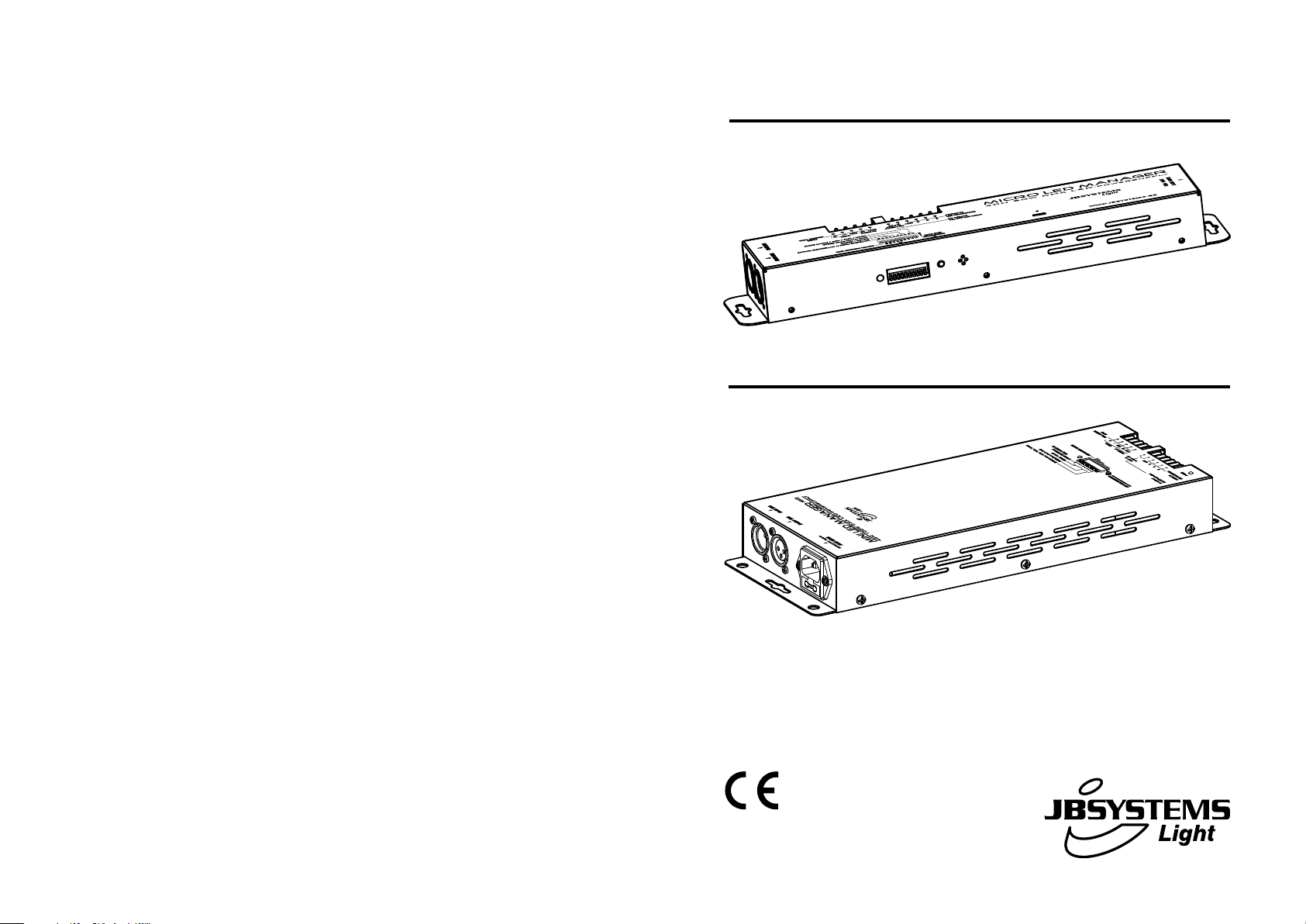
MICRO LED MANAGER
4CH 50W DMX LED-powersupply
WWW.BEGLEC.COM
MINI LED MANAGER
Mk2
4CH 100W DMX LED-powersupply
Operation Manual
Mode d'emploi
Gebruiksaanwijzing
Bedienungsanleitung
Manual de instrucciones
Manual do utilizador
EN
FR
NL
DE
ES
PT
Copyright © 2009 by BEGLEC comm.v.a.
‘t Hofveld 2 ~ B1702 Groot-Bijgaarden ~ Belgium
Reproduction or publication of the content in any manner, without express permission of the publisher, is prohibited.
Version: 1.0
Page 2
EN - DISPOSAL OF THE DEVICE
Dispose of the unit and used batteries in an environment friendly manner
according to your country regulations.
FR - DÉCLASSER L’APPAREIL
Débarrassez-vous de l’appareil et des piles usagées de manière écologique
Conformément aux dispositions légales de votre pays.
NL - VERWIJDEREN VAN HET APPARAAT
Verwijder het toestel en de gebruikte batterijen op een milieuvriendelijke
manier conform de in uw land geldende voorschriften.
DU - ENTSORGUNG DES GERÄTS
Entsorgen Sie das Gerät und die Batterien auf umweltfreundliche Art und
Weise gemäß den Vorschriften Ihres Landes.
ES - DESHACERSE DEL APARATO
Reciclar el aparato y pilas usadas de forma ecologica conforme a las
disposiciones legales de su pais.
PT - COMO DESFAZER-SE DA UNIDADE
Tente reciclar a unidade e as pilhas usadas respeitando o ambiente e em
conformidade com as normas vigentes no seu país.
Page 3
ENGLISH OPERATION MANUAL
OPERATION MANUAL
Thank you for buying this JB Systems®product. To take full advantage of all possibilities, please read these
operating instructions very carefully.
FEATURES
This unit is radio-interference suppressed. This product meets the requirements of the current European and
national guidelines. Conformity has been established and the relevant statements and documents have been
deposited by the manufacturer.
Extremely versatile power supply for all kinds of passive RGB LED-projectors.
Different standalone working modes:
Fixed color mode: Instant access to 16 pre-programmed colors
Auto chase mode: 16 different color chases with 8 different speeds.
Sound chase mode: 16 different color chases with audio triggering
Fade chase mode: 16 different color chases fading smoothly at 8 different speeds.
Any wall-switch can be used to turn the LED output on/off, even when used in DMX-mode!
All functions can be controlled:
Directly on the on the Micro Led Manager
With an optional LED WALL DIMMER (special interface)
With an optional LEDCON-02 remote
With a 300Watt LED Manager
By any standard DMX-controller
Several Micro Led Managers can be used in Master/slave mode to create high power, fully synchronized
setups.
Micro LED Manager: 50Watt power 24Vdc output. (R+G+B) with short-circuit protections
Mini LED Manager Mk2: 100Watt power 24Vdc output. (R+G+B) with short-circuit protections
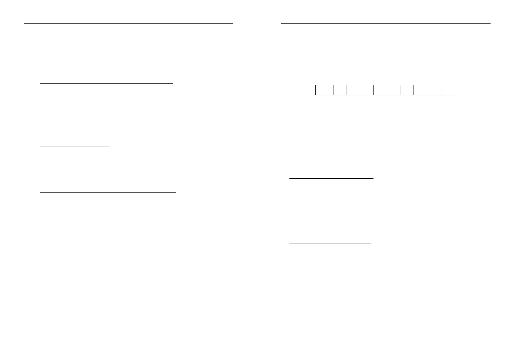
4 DMX channels needed: Ch1=red, Ch2=green, Ch3=Blue, Ch4=Dimmer/strobe.
Enclosure prepared for easy installing against the wall.
No fan cooling: completely silent!
BEFORE USE
Check the contents:
Check that the carton contains the following items:
Micro Led Manager or Mini LED Manager Mk2
Mains cable
Output conversion cable
User manual
Some important instructions:
Before you start using this unit, please check if there’s no transportation damage. Should there be any, do
not use the device and consult your dealer first.
Important: This device left our factory in perfect condition and well packaged. It is absolutely necessary
for the user to strictly follow the safety instructions and warnings in this user manual. Any damage caused
by mishandling is not subject to warranty. The dealer will not accept responsibility for any resulting defects
or problems caused by disregarding this user manual.
Keep this booklet in a safe place for future consultation. If you sell the fixture, be sure to add this user
manual.
To protect the environment, please try to recycle the packing material as much as possible.
ENGLISH OPERATION MANUAL
SAFETY INSTRUCTIONS:
CAUTION
The lightning flash with arrowhead symbol within the equilateral triangle is intended to alert the
use or the presence of un-insulated “dangerous voltage” within the product’s enclosure that may
be of sufficient magnitude to constitute a risk of electric shock.
The exclamation point within the equilateral triangle is intended to alert the user to the presence
of important operation and maintenance (servicing) instructions in the literature accompanying
this appliance.
This symbol means: indoor use only
This symbol means: Read instructions
This symbol means: Lamp Control Gear
To prevent fire or shock hazard, do not expose this appliance to rain or moisture.
To avoid condensation to be formed inside, allow the unit to adapt to the surrounding temperatures when
bringing it into a warm room after transport. Condense sometimes prevents the unit from working at full
performance or may even cause damages.
This unit is for indoor use only.
Don’t place metal objects or spill liquid inside the unit. No objects filled with liquids, such as vases, shall be
placed on this appliance. Electric shock or malfunction may result. If a foreign object enters the unit,
immediately disconnect the mains power.
No naked flame sources, such as lighted candles, should be placed on the appliance.
Don’t cover any ventilation openings as this may result in overheating.
Prevent use in dusty environments and clean the unit regularly.
Keep the unit away from children.
Inexperienced persons should not operate this device.
Maximum save ambient temperature is 40°C. Don’t use this unit at higher ambient temperatures.
Always unplug the unit when it is not used for a longer time or before you start servicing.
The electrical installation should be carried out by qualified personal only, according to the regulations for
electrical and mechanical safety in your country.
Check that the available voltage is not higher than the one stated on the rear panel of the unit.
The socket inlet shall remain operable for disconnection from the mains.
The power cord should always be in perfect condition: switch the unit immediately off when the power cord
is squashed or damaged. It must be replaced by the manufacturer, its service agent or similarly qualified
persons in order to avoid a hazard
Never let the power-cord come into contact with other cables!
This appliance must be earthed to in order comply with safety regulations.
In order to prevent electric shock, do not open the cover. Apart from the mains fuse there are no user
serviceable parts inside.
Never repair a fuse or bypass the fuse holder. Always replace a damaged fuse with a fuse of the same
type and electrical specifications!
In the event of serious operating problems, stop using the appliance and contact your dealer immediately.
Please use the original packing when the device is to be transported.
Due to safety reasons it is prohibited to make unauthorized modifications to the unit.
CAUTION: To reduce the risk of electric shock, do not
remove the top cover. No user-serviceable parts inside.
Refer servicing to qualified service personnel only.
MAINTENANCE
Clean by wiping with a polished cloth slightly dipped with water. Avoid getting water inside the unit. Do not
use volatile liquids such as benzene or thinner which will damage the unit.
Attention: We strongly recommend internal cleaning to be carried out by qualified personnel!
JB SYSTEMS® 1/57 MICRO/MINI LED MANAGER Mk2
JB SYSTEMS® 2/57 MICRO/MINI LED MANAGER Mk2
Page 4
ENGLISH OPERATION MANUAL
Dipswitch
setting
Auto/Fade Mode
Dipswitch
setting
Function
DIP10 = OFF
DMX
/ Slave operation
DIP10 = ON
Master
operation
(stand-alone)
ENGLISH OPERATION MANUAL
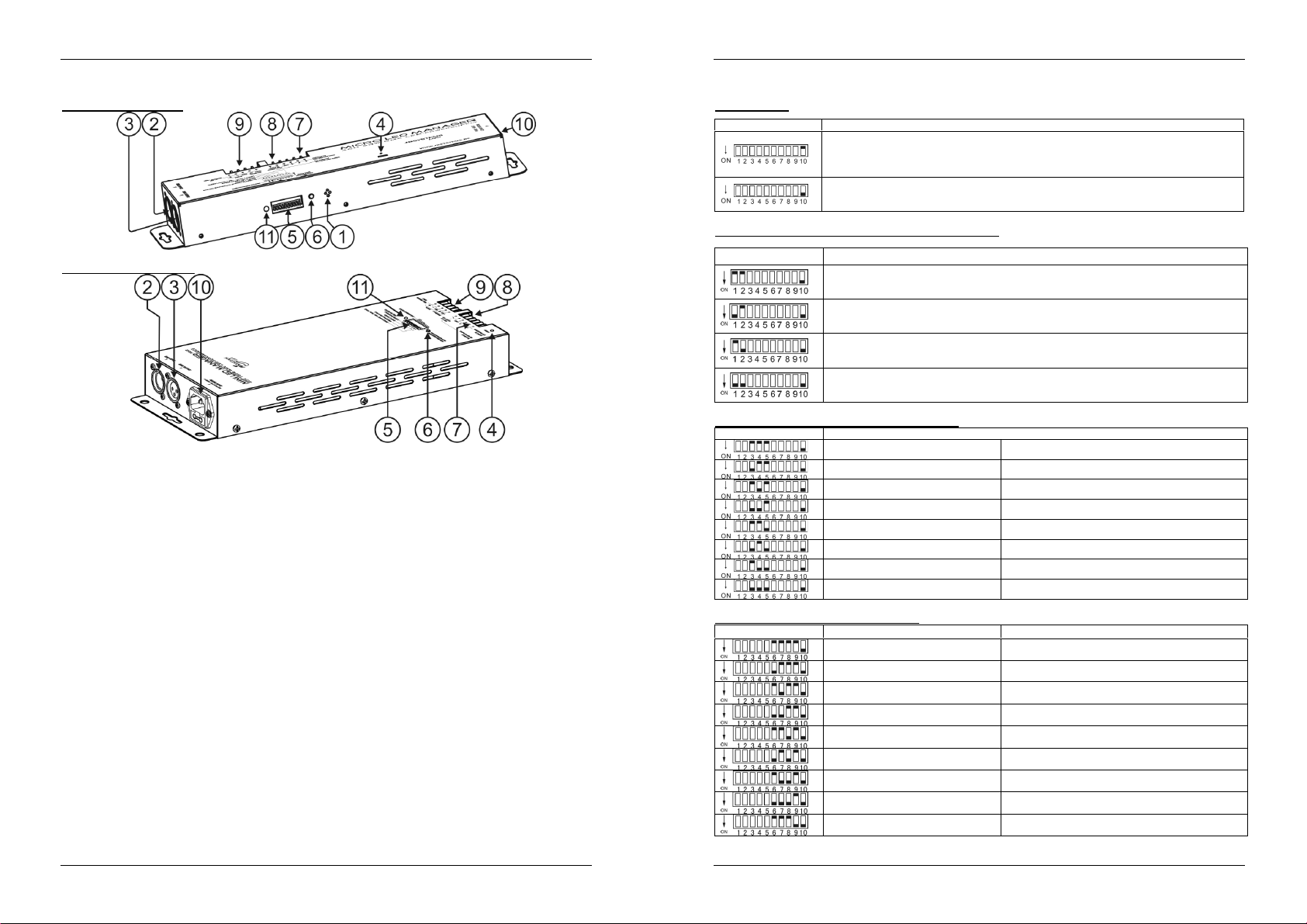
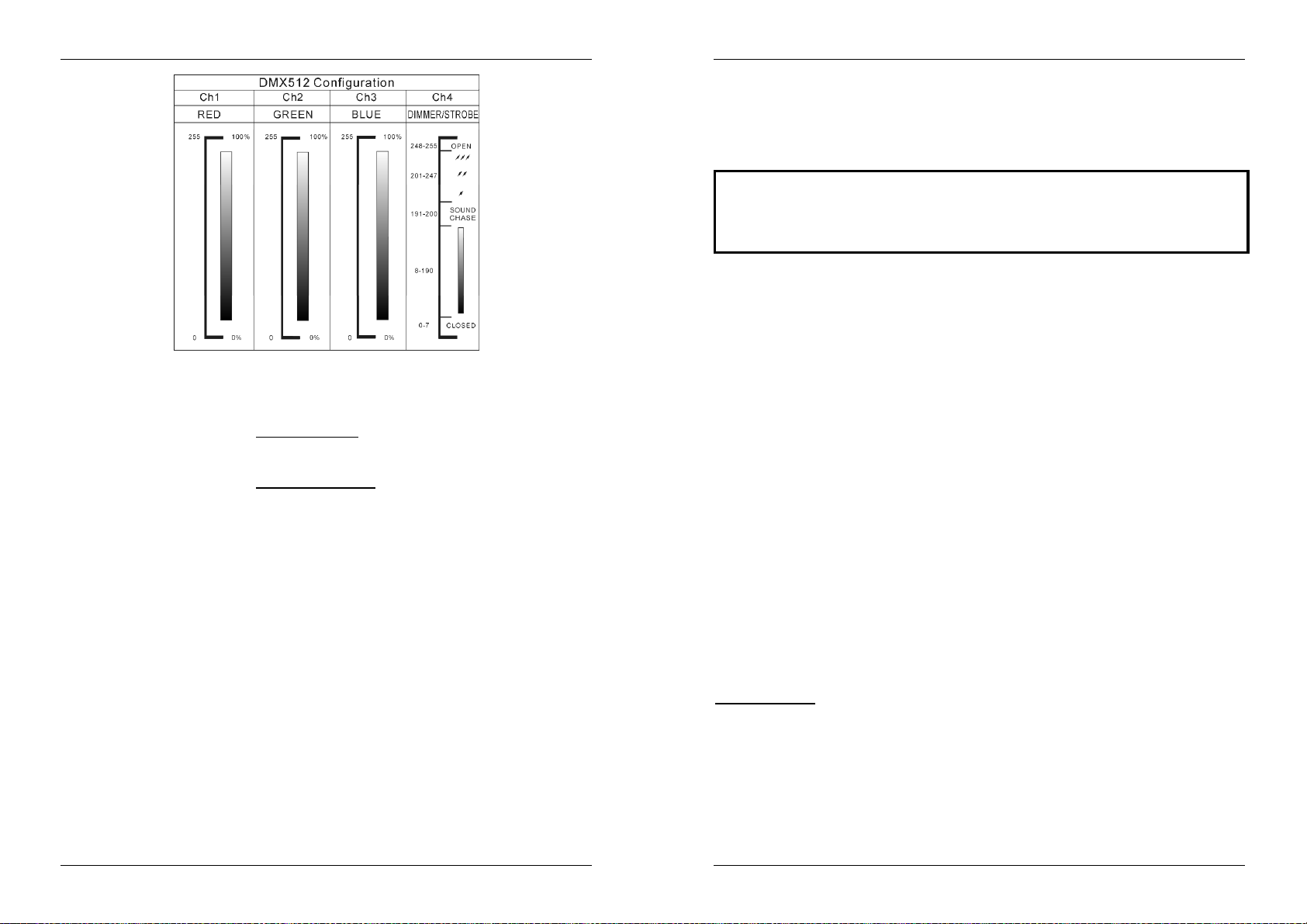
FUNCTIONS
MICRO LED MANAGER
MINI LED MANAGER Mk2
1. INTERNAL MICRO: used for sound activated chases.
2. DMX INPUT: 3pin male XLR-connector used to connect universal DMX-cables. This input receives
instructions from a DMX-controller or from another Micro / Mini LED Manager when used in master/slave
mode.
3. DMX OUTPUT: 3pin female XLR-connector used to connect the Micro Led Manager with the next DMX
appliance in the chain or with another Micro / Mini LED Manager when used in master/slave mode. The
Micro / Mini LED Manager can also be used as controller for other LED projectors like for example “LED
PAR56/64”
4. POWER ON LED: used to check if the Micro / Mini LED Manager is connected to the mains.
5. DIP SWITCHES: when used in DMX mode (DIP10 = OFF) you can set the DMX-starting address of the
unit. When used in stand-alone mode (master, DIP10 = ON), you can use the DIP-switches to set
different pre-programmed options.
6. AUTO DMX ADDRESS BUTTON: see further to learn how to set the DMX address easily.
7. OUTPUT TERMINALS: used to connect different 24Vdc common anode LED projectors. You can
connect any 4pole electrical wire to connect the LED-projectors to this output. However to make life
easier for you we suggest using the special CCM-50 cable (role = 50m). The wires in this cable
correspond to the colors of the LEDs .
8. ANALOG SWITCH INPUT: used to connect any external analog switch. This external switch can be
used to switch the general output of the Micro / Mini LED Manager on/off. (external blackout) See
further for more information on how to connect the analog switch.
9. WALL DIMMER INPUT: used to connect our LED WALL DIMMER, a small LED controller that fits in any
standard “electrical wall box”. See further for more information on how to connect the LED WALL
DIMMER.
10. MAINS INPUT: with IEC socket, connect the supplied mains cable here.
11. STATUS LED: shows the status of the unit, should blink when DMX is detected.
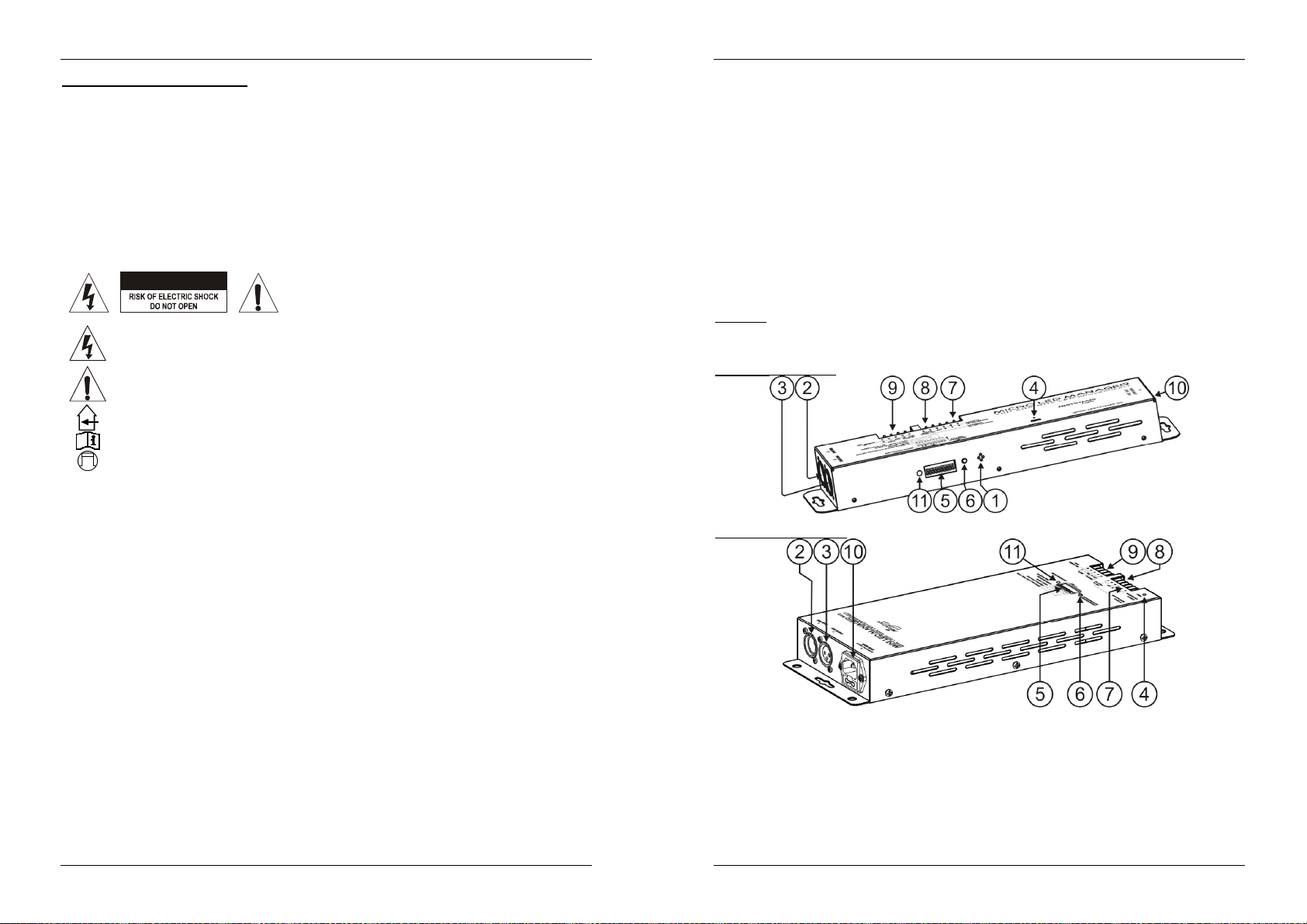
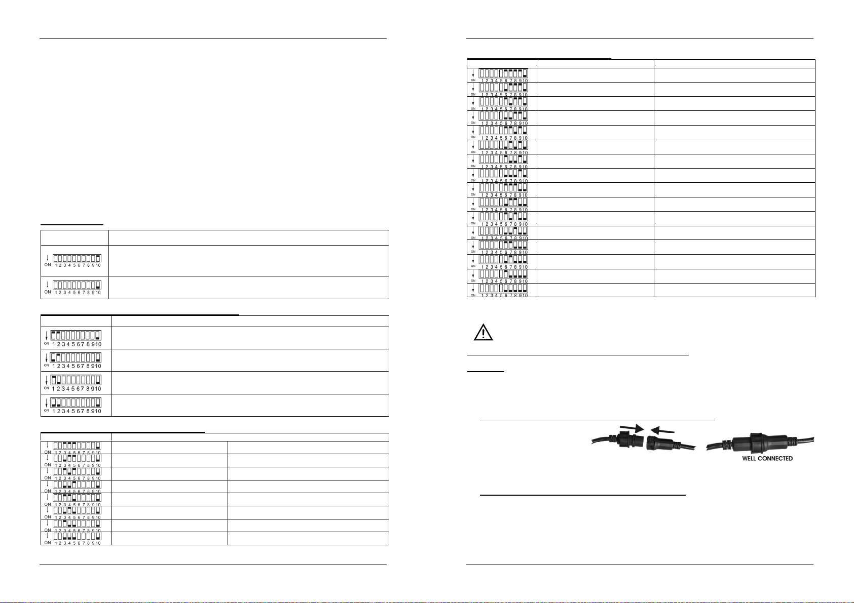
DIP SWITCH SETTINGS
Dip switch 10:
You can use the automatic DMX addressing feature or traditional DIP-switches.
In the chapter DMX-addressing, we explain how DMX-addressing can be done.
Use the dipswitches 1~9 to set the mode, speed, patterns, fixed color color…etc functions.
Below each of these functions is explained in detail.
Dip switches 1&2: Mode (Sound/auto/fade/fixed color):
Dipswitch setting MODE
SOUND: internal microphone triggers the selected patterns.
AUTO: the selected pattern runs automatically at the desired speed.
FADE: the colors of the selected pattern fade smoothly at the desired speed.
FIXED COLOR: use DIP-switches 6, 7, 8 & 9 to select the desired colors.
Dip switches 3,4 & 5:Speed (from fast to slow):
Speed 1 Fast
Speed 2
Speed 3
Speed 4
Speed 5
Speed 6
Speed 7
Speed 8 Slow
DIP switches 6,7 ,8 & 9: Chase & Color:
Dipswitch setting SOUND & AUTO MODE FIXED COLOR MODE
Standard chase White
Bright chase Red
Mood chase Orange
Spectrum random chase Amber
Spectrum sequence chase Yellow
Dynamic chase Light Yellow
Chase Red – Cyan Apple Green
Chase Green – Purple Light Green
Chase Blue – Red Green
JB SYSTEMS® 3/57 MICRO/MINI LED MANAGER Mk2
JB SYSTEMS® 4/57 MICRO/MINI LED MANAGER Mk2
Page 5

ENGLISH OPERATION MANUAL
ENGLISH OPERATION MANUAL
Chase Yellow – Blue Cyan
Chase Red – Green Blue
Chase Yellow – Green Deep Blue
Chase Cyan – Orange Purple
Chase Green - Light purple Light Purple
Chase Red – Yellow Magenta
Chase Gold Yellow - Blue Pink
ELECTRICAL INSTALLATION
The electrical installation should be carried out by qualified personal only, according to the
regulations for electrical and mechanical safety in your country.
How to connect the LED-projectors to the output of the unit:
Important: Switch the Micro / Mini LED Manager OFF before you install the LED-projectors! The
maximum total load of the Micro Led Manager is 50W, spread over 3 colors: each of the 3 colors
has a max. load of 16W ~ 17W! The maximum total load of the Mini Led Manager Mk2 is 100W,
spread over 3 colors: each of the 3 colors has a max. load of 33W!
Two different types of passive LED projectors can be connected:
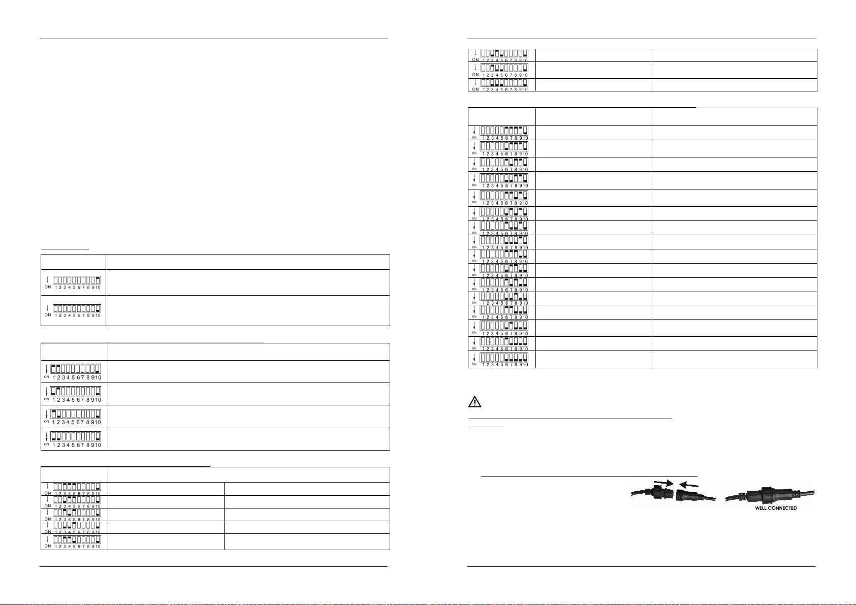
A. LED Projectors with a special 4pin connector (ex. LED STRIP):
Use the supplied conversion
cable and connect the
internal 4 wires to the
corresponding 4 terminals of
the MICRO / MINI LED
MANAGER. Fix all projectors properly and daisy chain the in/output cables until you reach the
maximum allowed load. Make sure to fasten the plastic ring of the connector.
B. LED Projectors with open wires (ex. LED GROUND LIGHT):
Simply connect the colored wires to the corresponding terminals on the LED MICRO MANAGER.
Make sure not to exceed the maximum allowed load:
White wire: This is the common wire (anode)
Red wire: This the power for the red LEDs.
Green wire: This the power for the green LEDs Blue wire: This the power for the blue LEDs
Remark: the outputs to the LED-projectors are short circuits protected. However when a short circuit
occurred, it must be reset: disconnect the Micro / Mini LED Manager for about 10seconds from the mains
and plug it back in.
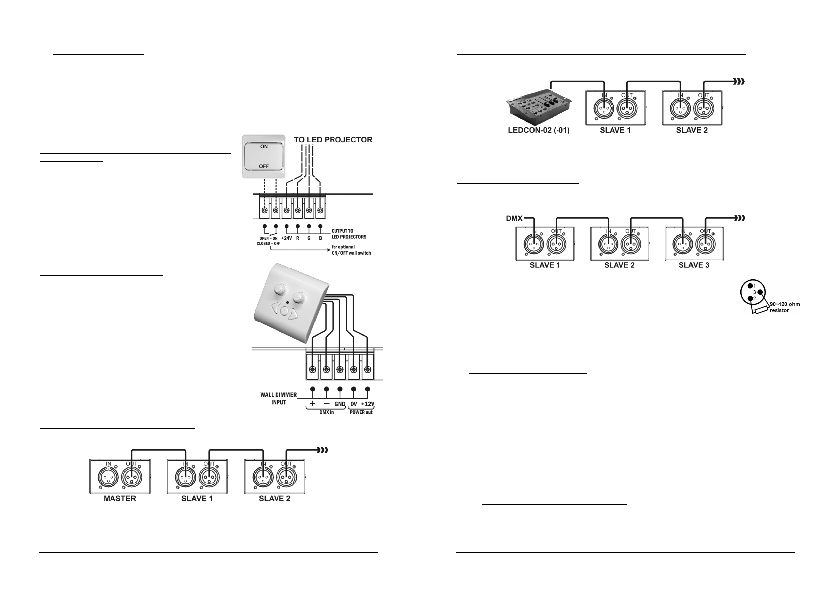
Connecting an external analog switch for blackout:
Using any ordinary on/off switch, you can put the output of the
Micro / Mini LED Manager in blackout, even if it’s controlled
by DMX: for example you can use a regular “wall switch” to
turn the LED-light on/off at any moment!
Connected wall switch in OFF position (contacts open):
output = ON
Connected wall switch in ON position (contacts closed):
output = OFF (blackout)
Connecting the optional LED WALL DIMMER:
The LED WALL DIMMER is a small, easy to use, controller
that can be installed in any standard wall connection box. This
controller can be connected directly to the Micro / Mini LED
Manager. The 0V & +12V should be connected through a
normal 2wire cable. The DMX-signal should be connected
using a good quality balanced DMX-cable with good
shielding.
Remark 1: the Micro / Mini LED Manager should be set to
DMX-address 001, using the traditional DIP switches (see
“DMX addressing to learn how to do this)
Remark 2: if you want to control more than 1 (Micro) LED
manager, just connect the LED Managers together with the
DMX in/outputs and put all DMX addresses to 001.
Electrical installation in Master/slave-mode:
You need to “daisy chain” the DMX in/outputs of 2 or
more units with a good quality balanced cable
Switch the unit with the free DMX-input connector to master, the other units are automatically switched
as slaves. The DIP-switches on the slave units are disabled.
Electrical installation in Master/slave-mode with the LEDCON-02 remote:
You need to “daisy chain” the DMX in/outputs of 1 or more units with the output of the LEDCON-02
remote using a good quality balanced cable
The LEDCON-02 remote will be used to control all connected slaves. The Micro / Mini LED Managers
are automatically switched as slaves. The DIP-switches on the slave units are disabled.
Electrical installation in DMX-mode:
The DMX-protocol is a widely used high speed signal to control intelligent light equipment. You need to
“daisy chain” your DMX controller and all the connected units with a good quality balanced cable
JB SYSTEMS® 5/57 MICRO/MINI LED MANAGER Mk2
To prevent strange behavior of the light effects, due to interferences, you must use
a 90Ω to 120Ω terminator at the end of the chain. Never use Y-splitter cables, this
simply won’t work!
JB SYSTEMS® 6/57 MICRO/MINI LED MANAGER Mk2
Page 6
ENGLISH OPERATION MANUAL
ENGLISH OPERATION MANUAL
DIP-switch 10 must be set to OFF on all units. Each unit in the chain needs its proper start address so it
knows which commands from the DMX-controller it has to decode. When you need a lot of power you
can use several Micro / Mini LED Managers and give them the same start address. See the previous
chapter to learn how to set the DMX addresses.
DMX ADDRESSING
How to set the DMX addresses:
There are 3 ways to set the DMX-address of the units. If you use setting options A or B you MUST set
ALL DIP-switches to OFF position.
A. Setting individual DMX-addresses per Micro / Mini LED Manager:
Make sure that ALL DIP-switches are set to OFF position!
Make sure the DMX cables of all units are connected.
Connect the first unit to a universal DMX controller.
Connect all units to the mains so they are switched on.
Set all DMX-channels on your DMX-controller to zero (value 000).
Set the DMX-channel, that you want to assign as DMX-start address on your Micro / Mini LED
Manager to maximum (value 255)
Press the “Auto DMX address” button (6) on the Micro / Mini LED Manager shortly.
If you want to set another unit to the same DMX-start address, simply press it’s “Auto DMX
address” button (6) and it will receive the same address.
Done!
An example to make things clear:
We will set the DMX start address of a Micro / Mini LED Manager to 106:
Connect the Micro / Mini LED Manager to the DMX-controller as described above and make
sure all is switched on.
Set all DMX-channels on the controller to zero (000)
Now set DMX-channel 106 to maximum (255)
Press the “Auto DMX address” button (6) on the Micro / Mini LED Manager shortly.
Done! Your Micro / Mini LED Manager now has DMX address 106!
B. Automatic DMX-addressing, starting from any given start address:
To save a lot of time (imagine the time it takes to set the DIP switches of 16 units…) you can set the
DMX addresses of all units in the DMX-chain just by the push of a button. No need to calculate the
starting address of each individual unit, this will be done for you!
Make sure that ALL DIP-switches are set to OFF position!
Make sure the DMX cables of all units are connected.
Connect the first unit to a universal DMX controller.
Connect all units to the mains so they are switched on.
Set all DMX-channels on your DMX-controller to zero (value 000).
Set the DMX-channel, that you want to assign as DMX-start address on your Micro / Mini LED
Manager, to maximum (value 255)
Press the “Auto DMX address” button (6) on the first Micro / Mini LED Manager in the chain for
about 5seconds.
Done! The first Micro / Mini LED Manager in the chain will receive the DMX-start address you
chose and it will automatically calculate and program the DMX addresses of all the other units in
the DMX-chain!
An example to make things clear:
We want to set the DMX-addresses of 16 units, the DMX start address of the first Micro / Mini LED
Manager must be 202:
Connect all Micro / Mini LED Manager to the DMX-controller as described above and make sure
all are switched on.
Set all DMX-channels on the controller to zero (000)
Now set DMX-channel 202 to maximum (255)
Press the “Auto DMX address” button (6) on the first Micro / Mini LED Manager in the chain for
about 5seconds.
Done! The first Micro / Mini LED Manager in the chain will receive DMX-start address 202 and
it will automatically calculate and program the DMX addresses of all the other units in the DMXchain! This means that the 2ndMicro / Mini LED Manager automatically receives address 206,
the 3rdhas address 210, …, until the 16thMicro / Mini LED Manager who automatically receives
start address 262.
You just programmed 16 Micro / Mini LED Managers, this took you about 10seconds!!!
Remark: you can mix the units with other DMX-effects that don’t have the automatic DMXaddressing option. In that case you still have to set the DMX-addresses of these DMX-effects
manually! You can also mix the Micro / Mini LED Managers with other JB Systems LED products
that have the auto DMX-feature. They will also automatically receive their DMX-addresses.
C. Setting DMX-addresses using the DIP switches:
This is the traditional addressing method, this method should be used when used with the LED
WALL DIMMER. The first 9 DIP-switches correspond to a certain DMX-value:
You can combine the values of these switches to obtain any starting address between 1 and 512:
Begin address = 01 switch 1=ON values: 1
Begin address = 05 switch 1+3=ON values: 1+4 = 5
Begin address = 09 switch 1+4=ON values: 1+8 = 9
Begin address = 13 switch 1+3+4=ON values: 1+4+8 = 13
…
Begin address = 62 switch 2+3+4+5+6=ON values: 2+4+8+16+32 = 62
DIP #1 #2 #3 #4 #5 #6 #7 #8 #9
Value 1 2 4 8 16 32 64 128 256
OPERATING INSTRUCTIONS
A. Standalone 1unit:
Connect the LED projectors to the Micro / Mini LED Manager as indicated in the previous chapters.
Switch the unit on and refer to the chapter “DIP SWITCH SETTINGS” to make yourself familiar with
the various functions of the faders and buttons.
B. Two or more units in master/slave setup:
Connect the LED projectors to the Micro / Mini LED Managers as indicated in the previous chapters.
Connect the units with each other as explained in the chapter about electrical installations.
Switch the Micro / Mini LED Managers on. You can only use the controls on the master unit, the
controls on the slaves are disabled. Refer to the chapter “DIP SWITCH SETTINGS” to make yourself
familiar with the various functions of the faders and buttons on the master unit.
C. Connect the optional LEDCON-02 for remote control:
In most cases the MICRO / MINI LED MANAGER will be installed on a wall, close to the LED-projectors.
If you want to have easy access to its functions, you can connect the LEDCON-02 remote controller to
the (first) Micro / Mini LED Manager. The other connections are identical to those of the standalone or
master/slave setups. Don’t forget to perform the automatic addressing on the LEDCON-02!!!
D. Controlled by universal DMX-controller:
Connect the LED projectors to the Micro / Mini LED Manager(s) as indicated in the previous chapters.
Connect the Micro / Mini LED Manager(s) with all other DMX-appliances in the DMX-chain.
Switch all units on and set the proper DMX-addresses. (don’t forget to set DIP-switch 10 to OFF)
Switch your universal DMX-controller on and refer to the DMX chart below to control the connected
Micro / Mini LED Managers:
JB SYSTEMS® 7/57 MICRO/MINI LED MANAGER Mk2
JB SYSTEMS® 8/57 MICRO/MINI LED MANAGER Mk2
Page 7
ENGLISH OPERATION MANUAL
SPECIFICATIONS
Power Input: AC 100 ~ 250V (50Hz/60Hz)
Output voltage to LEDs: DC 24V common anode
Output power to LEDs:
DMX connections: 3pin XLR (DMX-512 standard)
DMX channels: 4 (CH1: red, CH2: green, CH3:blue, CH4:dimmer/strobe)
Audio input: Internal microphone
Size: see drawings on the last page
Weight: 1,00kg (Micro LED Manager)
Every information is subject to change without prior notice
You can download the latest version of this user manual on our website: www.beglec.com
Micro LED Manager: 1x 50W max
o Red: 16W ~ 17W max.
o Green: 16W ~ 17W max.
o Blue: 16W ~ 17W max.
Mini LED Manager Mk2: 1x 100W max
o Red: 33W max.
o Green: 33W max.
o Blue: 33W max.
1,70kg (Mini LED Manager Mk2)
FRANCAIS MODE D’EMPLOI
MODE D’EMPLOI
Nous vous remercions d’avoir acheté ce produit JB Systems®. Veuillez lire ce mode d’emploi très
attentivement afin de pouvoir exploiter toutes les possibilités de cet appareil.
EN VOUS INSCRIVANT POUR LA LETTRE D’INFORMATION VOUS SEREZ TOUJOURS
TENU AU COURANT DES DERNIERES NOUVELLES CONCERNANT NOS PRODUITS:
NOUVEAUTES, ACTIONS SPECIALES, JOURNEES PORTES OUVERTES, ETC.
SURFEZ SUR: WWW.BEGLEC.COM ET INSCRIVEZ-VOUS
CARACTERISTIQUES
Cet appareil ne produit pas d’interférences radio. Il répond aux exigences nationales et européennes. La
conformité a été établie et les déclarations et documents correspondants ont été déposés par le fabricant.
Alimentation polyvalente pour toutes sortes de projecteurs RVB LED passifs
Différents modes de fonctionnement sont possibles :
Fixed colors mode: accès immédiat aux 16 couleurs préprogrammées
Auto chase mode : 16 séquences de poursuite différentes, défilement des couleurs à 8 vitesses
différentes
Sound chase mode : 16 séquences de poursuite différentes, défilement des couleurs réagissant au
signal audio
Fade chase mode: 16 séquences de poursuite différentes, défilement des couleurs en fondu enchaîné,
à 8 vitesses différentes
N'importe quel interrupteur mural peut être utilisé pour éteindre/allumer les projecteurs connectés, même
quand l’appareil est utilisé en mode DMX.
Toutes les fonctions peuvent être contrôlées de différentes manières :
directement à partir du MICRO / MINI LED MANAGER
au moyen d’un gradateur mural encastrable (interface spécial)
au moyen d'une commande à distance LEDCON-02
au moyen d'un LED MANAGER de 300 watts
au moyen de n'importe quel contrôleur DMX standard
Plusieurs MICRO / MINI LED MANAGERs peuvent être utilisés ensemble en mode maître/esclave pour
obtenir une puissance élevée et un ensemble entièrement synchronisé
Micro LED Manager: 50 watts de puissance avec une sortie en 24V CA (R+G+B) et avec coupe-circuits de
protection
Mini LED Manager Mk2: 100 watts de puissance avec une sortie en 24V CA (R+G+B) et avec coupe-
circuits de protection
Utilisation de 4 canaux DMX : Ch1=rouge; Ch2=vert ; Ch3=bleu ; Ch4=Dimmer/stroboscope
Le boîtier est conçu pour permettre une installation facile sur un mur
Pas de ventilation forcée par ventilateur, ce qui fait que l’appareil ne fait aucun bruit
JB SYSTEMS® 9/57 MICRO/MINI LED MANAGER Mk2
AVANT L’UTILISATION
Vérifiez le contenu:
Vérifiez si la boite contient bien les articles suivants :
MICRO LED MANAGER ou Mini LED Manager Mk2
Câble d’alimentation
Câble d'alimentation servant d'adaptateur
Mode d’emploi
JB SYSTEMS
®
10/57 MICRO/MINI LED MANAGER Mk2
Page 8
FRANCAIS MODE D’EMPLOI
ATTENTION
:
FRANCAIS MODE D’EMPLOI
Quelques instructions importantes:
Avant d’utiliser cet appareil, assurez-vous de l’absence de dommage lié au transport. En cas
d’endommagement, n’utilisez pas l’appareil et contactez le vendeur.
Important: Cet appareil a quitté notre usine en parfaite condition et bien emballé. Il est primordial que
l’utilisateur suive les instructions de sécurité et avertissements inclus dans ce manuel. La garantie ne
s’applique pas en cas de dommage lié à une utilisation incorrecte. Le vendeur ne prend pas la
responsabilité des défauts ou de tout problème résultant du fait de n’avoir pas tenu compte des mises en
garde de ce manuel.
Conservez ce manuel dans un endroit sûr pour toute consultation future. Si vous vendez l’appareil,
assurez-vous d’y joindre ce manuel également.
Afin de protéger l’environnement, merci de recycler les emballages autant que possible.
INSTRUCTIONS DE SECURITE:
CAUTION
La flèche dans un triangle met l'utilisateur en garde contre la présence de haute tension sans
isolation dans l'appareil, ce qui peut causer un risque d'électrocution.
Un point d'exclamation dans un triangle prévient de la présence d'instructions relatives au
fonctionnement et à la maintenance se trouvant dans le manuel fourni avec l'appareil.
Ce symbole signifie: uniquement pour usage à l'intérieur.
Ce symbole signifie : Lire le mode d’emploi.
Ce symbole signifie: Lamp Control Gear
Afin d’éviter tout risque d’incendie ou de décharge électrique, ne pas exposer cet appareil à la pluie ou
l’humidité.
Pour éviter la formation de condensation à l’intérieur de l’appareil, patientez quelques minutes pour laisser
l’appareil s’adapter à la température ambiante lorsqu’il arrive dans une pièce chauffée après le transport.
La condensation empêche l'appareil de fonctionner manière optimale, et elle peut même causer des
dommages.
Cet appareil est destiné à une utilisation à l’intérieur uniquement.
Ne pas insérer d’objet métallique ou renverser de liquide dans l’appareil. Aucun objet contenant un liquide,
tels que des vases, ne peut être placé sur cet appareil. Cela risquerait de provoquer une décharge
électrique ou un dysfonctionnement. Si un corps étranger est introduit dans l’appareil, déconnectez
immédiatement de la source d’alimentation.
Aucune source de flamme nue, telle que des bougies allumées, ne peut être placée sur l'appareil.
Ne pas couvrir les orifices de ventilation, un risque de surchauffe en résulterait.
Ne pas utiliser l'appareil dans un environnement poussiéreux et le nettoyer régulièrement.
Ne pas laisser l'appareil à portée des enfants.
Les personnes non expérimentées ne doivent pas utiliser cet appareil.
La température ambiante maximale d’utilisation de l’appareil est de 45°C. Ne pas l’utiliser au-delà de cette
température.
Débranchez toujours l’appareil si vous ne l’utilisez pas de manière prolongée ou avant d’entreprendre des
réparations.
Les installations électriques ne peuvent être faites que par du personnel qualifié et conformément aux
règlements de sécurité électrique et mécanique en vigueur dans votre pays.
Assurez-vous que la tension d’alimentation de la source d’alimentation de la zone dans laquelle vous vous
trouvez ne dépasse pas celle indiquée à l’arrière de l’appareil.
La prise sera toujours accessible pour que le cordon secteur puisse être enlevé à chaque moment.
Le cordon d’alimentation doit toujours être en condition parfaite. Mettez immédiatement l’unité hors tension
si le cordon est écrasé ou endommagé. Pour éviter tout risque de choc électrique, le cordon doit être
remplacé par le constructeur, son agent ou un technicien qualifié.
n’enlevez jamais le couvercle de l’appareil. Il n’y a aucune
pièce à l’intérieur de l’appareil que vous puissiez
remplacer vous-même. Confiez l’entretien uniquement à
des techniciens qualifiés.
afin de réduire le risque d’électrocution,
Ne laissez jamais le cordon d’alimentation entrer en contact avec d’autres câbles !
L’appareil doit être à la masse selon les règles de sécurité.
Utilisez toujours des câbles appropriés et certifiés lorsque vous installez l'appareil.
Pour éviter toute décharge électrique, ne pas ouvrir l’appareil. En dehors des ampoules et du fusible
principal, il n’y a pas de pièces pouvant être changées par l’utilisateur à l’intérieur.
Ne jamais réparer ou court-circuiter un fusible. Remplacez systématiquement un fusible endommagé par
un fusible de même type et ayant les mêmes spécifications électriques !
En cas de problèmes de fonctionnement sérieux, arrêtez toute utilisation de l’appareil et contactez votre
revendeur immédiatement.
Utilisez l’emballage d’origine si l’appareil doit être transporté.
Pour des raisons de sécurité, il est interdit d’apporter une quelconque modification à l’unité non
spécifiquement autorisée par les parties responsables.
ENTRETIEN
Nettoyez l’appareil à l’aide d’un chiffon doux, légèrement humide. Evitez d’introduire de l’eau à l’intérieur
de l’appareil. N’utilisez pas de produits volatiles tels le benzène ou le thinner qui peuvent endommager
l’appareil.
Attention: Nous conseillons que le nettoyage interne se fasse par une personne qualifiée.
FONCTIONS
MICRO LED MANAGER
MINI LED MANAGER Mk2
1. MICROPHONE INTERNE: micro intégré.
2. ENTRÉE DMX: Connecteur XLR mâle à 3 broches qui permet de connecter des câbles DMX. Cette
entrée reçoit des instructions provenant d’un contrôleur DMX ou, en mode maitre/esclave, d’un autre
MICRO / MINI LED MANAGER.
3. SORTIE DMX: Connecteur XLR femelle à 3 broches qui permet de connecter le MICRO / MINI LED
MANAGER à l’unité suivante de la chaîne DMX ou à un autre MICRO / MINI LED MANAGER en mode
master/slave. Le MICRO / MINI LED MANAGER peut aussi être utilisé en tant que contrôleur pour
d'autres projecteurs à LED, comme par exemple le modèle LED PAR 56/64.
4. LED D’ALIMENTATION : est utilisée pour vérifier si le Micro / Mini LED Manager est mis sous tension.
JB SYSTEMS
®
11/57 MICRO/MINI LED MANAGER Mk2
JB SYSTEMS
®
12/57 MICRO/MINI LED MANAGER Mk2
Page 9
FRANCAIS MODE D’EMPLOI
Réglage des inter
-
Réglage des inter
-
Fonction
DIP10 = OFF
Fonctionnement en mode maître/esclave
DIP10 = ON
Fonctionnement en mode autonome (stand alone)
FRANCAIS MODE D’EMPLOI
5. INTERRUPTEURS DIP : lorsque le mode DMX est utilisé (DIP 10 = OFF), vous pouvez régler l'adresse
DMX de départ de l'appareil. Lorsque le mode autonome est utilisé (DIP 10 = ON), vous pouvez utiliser
les interrupteurs DIP afin de régler les différentes options préprogrammées.
6. AUTO DMX ADDRESS: touche d’adressage DMX automatique. Voir plus loin pour plus d’informations
sur ce système qui facilite l’attribution des adresses DMX.
7. CONNECTEURS DE SORTIE : utilisé pour connecter les différents projecteurs à LED de 24V (CA,
anode commune). Vous pouvez connecter n’importe quel type de câble électrique à 4 fils pour relier les
projecteurs LED à cette sortie. Il est cependant plus facile d’utiliser le câble spécial CCM-50 (bobine de
50m). Les fils dans ce câble corresponds au couleurs des LEDs .
8. ENTREE POUR INTERRUPTEUR ANALOGIQUE : utilisé pour raccorder n'importe quel interrupteur
analogique externe. Cet interrupteur externe peut être utilisé pour alimenter ou couper la sortie générale
du MICRO / MINI LED MANAGER (black out externe Voir plus loin pour de plus amples informations
expliquant comment connecter cet interrupteur analogique.
9. WALL DIMMER INPUT: est utilisé pour connecter notre gradateur mural, un petit contrôleur LED qui
peut être encastré dans un boitier électrique mural standard. voir plus loin pour plus d’informations
concernant le raccordement du gradateur mural.
10.ALIMENTATION SECTEUR : munie d'une prise IEC. Raccordez le câble d’alimentation (fourni) à cette
prise.
11.LED TÉMOIN: clignote quand un signal DMX est détecté.
REGLAGE DES INTERRUPTEURS DIP
Dip switch 10:
rupteurs DIP
Vous pouvez utiliser le système d’adressage automatique ou les interrupteurs DIP traditionnels.
Dans le chapitre ‘adressage DMX’ nous expliquons comment effectuer l’adressage DMX
Utilisez les 9 premiers interrupteurs DIP pour régler le mode de fonctionnement, la vitesse, les
motifs, les couleurs fixes, ... et les autres fonctions.
Chacune de ces fonctions est expliquée en détail ci-dessous.
Interrupteurs DIP 1 & 2 : Mode (Sound/auto/fade/ FIXED COLOR) :
Réglage des interrupteurs DIP
MODE
SOUND: le micro interne déclenche l'enchaînement des motifs sélectionnés.
AUTO: le motif sélectionné évolue automatiquement à la vitesse désirée.
FADE: les couleurs du motif sélectionné faiblissent progressivement, à la vitesse désirée.
FIXED COLOR: utilisez les interrupteurs DIP 6, 7, 8 & 9 pour sélectionner les couleurs
désirées.
Interrupteurs DIP 3, 4 & 5 (vitesse rapide à lente) :
rupteurs DIP
Mode Auto/Fade
Vitesse 1 Rapide
Vitesse 2
Vitesse 3
Vitesse 4
Vitesse 5
Vitesse 6
Vitesse 7
Vitesse 8 Lente
interrupteurs DIP 6, 7, 8 & 9 : Séquences de poursuite et couleurs :
Réglage des inter-
rupteurs DIP
MODES SOUND & AUTO MODE COULEURS FIXES
Séquence de poursuite normale Blanc
Séquence de poursuite très
lumineuse
Séquence de poursuite d'ambiance Orange
Séquence de poursuite à spectre
lumineux aléatoire
Séquence de poursuite jouant sur le
spectre lumineux
Séquence de poursuite dynamique Jaune clair
Séquence de poursuite rouge - cyan Vert pomme
Séquence de poursuite vert - pourpre Vert clair
Séquence de poursuite bleu - rouge Vert
Séquence de poursuite jaune - bleu Cyan
Séquence de poursuite rouge - vert Bleu
Séquence de poursuite jaune - vert Bleu foncé
Séquence de poursuite cyan - orange Pourpre
Séquence de poursuite vert - pourpre
clair
Séquence de poursuite rouge - jaune Magenta
Séquence de poursuite jaune or bleu
Rouge
Ambre
Jaune
Pourpre clair
Rose
INSTALLATION ÉLECTRIQUE
L’installation électrique doit être faite uniquement par une personne qualifiée et selon les
règlements pour la sécurité électrique et mécanique dans votre pays.
Comment relier les projecteurs LED à la sortie de l'appareil:
Important: Coupez le MICRO / MINI LED MANAGER avant d’installer les projecteurs LED! La charge
maximale du MICRO LED MANAGER est 50W, répartie en 3 couleurs: chacune des 3 couleurs a une
charge maximale de 16W ~ 17W! La charge maximale du Mini Led Manager Mk2 est 100W, répartie en
3 couleurs: chacune des 3 couleurs a une charge maximale de 33W!
Deux types de projecteurs passifs LED peuvent être reliés:
A. Projecteurs LED avec connecteur spécial 4pin (ex. LED STRIP):
Utilisez le câble d'alimentation servant
d'adaptateur et connectez les 4 connecteurs
du Micro / Mini LED Manager aux 4 fils
correspondants des projecteurs à LED.
(dans la plupart des cas, les couleurs des fils correspondent aux couleurs des LED). Fixez correctement
tous les projecteurs en reliant les câbles d'entrée et de sortie de chaque appareil jusqu'à ce que vous
atteigniez la charge maximale autorisée. Veillez à attacher l'anneau en plastique aux connecteurs.
JB SYSTEMS
®
13/57 MICRO/MINI LED MANAGER Mk2
JB SYSTEMS
®
14/57 MICRO/MINI LED MANAGER Mk2
Page 10
FRANCAIS MODE D’EMPLOI
FRANCAIS MODE D’EMPLOI
B. Projecteurs à fils dénudés :
Connectez les fils colorés aux bornes correspondantes du LED MICRO MANAGER. Assurez vous de ne
pas dépasser la charge maximale autorisée :
Fil blanc : commun (anode)
Fil rouge : conducteur de puissance pour les LED rouges
Fil vert : conducteur de puissance pour les LED vertes
Fil bleu : conducteur de puissance pour les LED bleues
Remarque: les sorties pour les projecteurs LED sont protégés contre les court-circuit. Cependant, si vous
avez eu a faire à un court-circuit, vous devrez effectuer une mise à zéro: déconnectez le Micro / Mini LED
Manager pendant environ 10secondes du secteur, puis
rebranchez le.
Connexion d’un interrupteur analogique externe pour la
fonction black-out:
Vous pouvez mettre les sorties du Mini LED Manager en
blackout à l’aide de n’importe quel interrupteur (on/off). Vous
pouvez par exemple utiliser à tout moment un interrupteur
mural pour éteindre les effets LED, même si l’appareil est
contrôlé par DMX:!
Interrupteur mural en position ETEINT (contacts ouverts):
sortie = ALLUMÉ
Interrupteur mural en position ALLUMÉ (contacts
fermés): sortie = ETEINT (blackout)
Connexion du GRADATEUR MURAL:
Le GRADATEUR MURAL est un petit contrôleur mural, facile à
utiliser, qui peut être installé dans les boîtiers électriques muraux
standard. Ce contrôleur peut être branché directement sur le
Micro / Mini LED Manager. La sortie 0V & +12V doit être relié à
l’aide d’un câble à 2 fils normal. Le signal DMX devrait être
connecté à l’aide d’un câble DMX symétrique de bonne qualité,
pourvu d’un bon blindage.
Remarque 1: le Micro / Mini LED Manager devrait être réglé sur
l’adresse DMX 001, en utilisant les interrupteurs DIP (voir
“adressage DMX’’ pour plus d’explications)
Remarque 2: si vous voulez contrôler plusieurs (Micro) LED
manager, il suffit de relier les LED Managers entre eux en
utilisant les entrées/sorties DMX, et de mettre toutes les
adresses sur 001.
Installation électrique en mode maître/esclave:
Vous devez relier les entrées et les sorties DMX de 2 ou plusieurs appareils avec un câble symétrique
de bonne qualité
Réglez l'appareil dont le connecteur d'entrée DMX est libre en mode master, et les autres appareils
seront automatiquement mis en mode esclave. Les interrupteurs DIP des appareils esclaves seront mis
hors service.
Installation électrique en mode maître/esclave avec commande à distance LEDCON-02:
Vous devez relier les entrées/sorties DMX d’un ou plusieurs appareils avec la sortie du LEDCON-02
avec un bon câble symétrique
La commande à distance LEDCON-02 sera utilisée pour commander tous les esclaves de la chaîne
d'appareils. Les MICRO / MINI LED MANAGERs seront automatiquement mis en mode esclave. Les
interrupteurs DIP des appareils esclaves seront mis hors service.
Installation électrique en mode DMX:
Le protocole DMX est largement employé, c’est un signal à grande vitesse pour commander
l'équipement lumière. Vous devez relier votre contrôleur DMX et tous les appareils, avec un bon câble
symétrique.
Afin d’éviter que vos effets de lumière se comportent de manière étrange, à cause
d’interférences, utilisez des bouchons de 90Ω à 120Ω en fin de chaîne. N’utilisez
jamais des câbles de dérivation, ceci ne fonctionne pas!
L'interrupteur DIP 10 doit être réglé sur OFF sur tous les appareils. Chaque appareil
de la chaîne doit avoir sa propre adresse de démarrage afin de savoir quelles
commandes du contrôleur DMX il doit décoder. Si vous avez besoin de beaucoup de puissance, vous
pouvez employer plusieurs MICRO / MINI LED MANAGERs et leur donner la même adresse de
démarrage. Reportez-vous au chapitre précédent pour savoir comment régler les adresses DMX.
ADRESSAGE DMX
Comment régler les adresses DMX:
Il existe trois façons de régler les adresses DMX des appareils. Si vous utilisez les possibilités A ou B,
vous DEVEZ mettre tous les interrupteurs DIP en position OFF
A. Régler les adresses DMX par Micro / Mini LED Manager:
Assurez-vous que TOUS les interrupteurs DIP sont en position OFF!
Assurez-vous que les câbles DMX de tous les appareils sont branchés.
Connectez le premier appareil sur le contrôleur DMX.
Branchez tous les appareils sur le secteur pour qu’ils soient tous allumés.
Mettez tous les canaux DMX de votre contrôleur DMX sur zéro. (valeur 000).
Mettez le canal DMX, que vous voulez assigner comme adresse de départ sur le Micro / Mini LED
Manager sur maximum (valeur 255)
Poussez brièvement le bouton “Adressage DMX auto” (6) du Micro / Mini LED Manager.
Si vous voulez mettre un autre appareil sur la même adresse de départ, vous devez également
pousser le bouton “Adressage DMX auto” (6) de cet appareil.
Fini!
Un exemple pour rendre les choses claires:
Si vous souhaitez mettre l’adresse de départ d’un Micro / Mini LED Manager sur 106:
Connectez le Micro / Mini LED Manager sur le contrôleur DMX comme décrit ci-dessus et
allumez l’ensemble.
Mettez tous les canaux DMX de votre contrôleur DMX sur zéro. (valeur 000).
JB SYSTEMS
®
15/57 MICRO/MINI LED MANAGER Mk2
JB SYSTEMS
®
16/57 MICRO/MINI LED MANAGER Mk2
Page 11

FRANCAIS MODE D’EMPLOI
FRANCAIS MODE D’EMPLOI
Mettez le canal DMX 106 sur maximum (valeur 255)
Poussez brièvement le bouton “Adressage DMX auto” (6) du Micro / Mini LED Manager.
Fini! l’adresse de départ de votre Micro / Mini LED Manager est 106!
B. Régler automatiquement les adresses DMX:
Pour gagner du temps (imaginez le temps qu’il vous faudra pour régler les interrupteurs DIP de 16
appareils…) vous pouvez régler les adresses DMX de tous les appareils dans la chaîne DMX juste
en appuyant sur un bouton. Pas besoin de calculer l’adresse de départ de chaque appareil, cela
sera fait à votre place!
Assurez-vous que TOUS les interrupteurs DIP sont en position OFF!
Assurez-vous que les câbles DMX de tous les appareils sont branchés.
Connectez le premier appareil sur le contrôleur DMX.
Branchez tous les appareils sur le secteur pour qu’ils soient tous allumés.
Mettez tous les canaux DMX de votre contrôleur DMX sur zéro. (valeur 000).
Mettez le canal DMX, que vous voulez assigner comme adresse de départ sur le premier Micro /
Mini LED Manager de la chaîne, sur maximum (valeur 255)
Poussez le bouton “Adressage DMX auto” (6) du premier Micro / Mini LED Manager de la chaîne
pendant environ 5 secondes. (tous les projecteurs clignotes 1x)
Fini! Le premier Micro / Mini LED Manager de la chaîne reçoit l’adresse de départ que vous
avez choisi. Les adresses de départ des autres projecteurs de la chaîne seront calculés et
distribués automatiquement !
Un exemple pour rendre les choses claires:
Imaginons que nous voulions donner des adresses DMX à 16 Micro / Mini LED Manager.
L’adresse de départ du premier Micro / Mini LED Manager de la chaîne est fixée sur 202.
Connectez les Micro / Mini LED Manager sur le contrôleur DMX comme décrit ci-dessus et
allumez l’ensemble.
Mettez tous les canaux DMX de votre contrôleur DMX sur zéro. (valeur 000).
Mettez le canal DMX 202 sur maximum (valeur 255)
Poussez le bouton “Adressage DMX auto” (6) du premier Micro / Mini LED Manager pendant
environ 5sec.
Fini! Le premier Micro / Mini LED Manager de la chaîne reçoit l’adresse 202. Les adresses de
départ des autres Micro / Mini LED Manager de la chaîne seront calculés et distribués
automatiquement: le deuxième Micro / Mini LED Manager reçoit l’adresse 206, le troisième
l’adresse 210, …, jusqu’au seizième Micro / Mini LED Manager qui reçoit l’adresse 262.
Vous venez de programmer 16 projecteurs en 10 secondes !!!
Remarque: vous pouvez mélanger les appareils ensemble avec d’autres effets DMX qui ne
possèdent pas l’option adressage DMX automatique. Dans ce cas, il vous restera à régler les
adresses DMX de ces effets DMX manuellement! Vous pouvez également mélanger les Micro / Mini
LED Manager avec d’autres produits LED de la marque JB Systems qui possèdent la fonction
d’adressage DMX automatique. Ils recevront également leur adresse DMX automatiquement.
C. Adressage DMX à l’aide de interrupteurs DIP:
Ceci est la méthode d’adressage traditionnelle. Cette méthode doit être utilisée avec le gradateur
mural.
Les 9 premiers interrupteurs DIP correspondent à une certaine valeur DMX.
DIP #1 #2 #3 #4 #5 #6 #7 #8 #9
Valeur 1 2 4 8 16 32 64 128 256
Combinez ces valeurs pour obtenir des adresses de démarrage comprises entre 1 et 512:
Adresse = 01 DIP 1=ON valeurs: 1
Adresse = 05 DIP 1+3=ON valeurs: 1+4 = 5
Adresse = 09 DIP 1+4=ON valeurs: 1+8 = 9
Adresse = 13 DIP 1+3+4=ON valeurs: 1+4+8 = 13
…
Adresse = 62 DIP 2+3+4+5+6=ON valeurs: 2+4+8+16+32 = 62
CONSIGNES D’UTILISATION
A. 1 appareil autonome:
Reliez les projecteurs LED aux MICRO / MINI LED MANAGER comme indiqué dans les chapitres
précédents.
Branchez l’appareil et consultez le chapitre ‘Réglages des interrupteurs DIP' pour vous familiariser
avec les diverses fonctions des curseurs et des touches.
Dans ce mode vous pouvez également régler l'horloge et employer les 3 minuteries ‘on/off’ comme
décrit dans le chapitre précédent.
B. Installation de 2 ou plus d’appareils en mode maître/esclave:
Reliez les projecteurs LED aux MICRO / MINI LED MANAGERs comme indiqué dans les chapitres
précédents.
Reliez les appareils les uns aux autres comme expliqué dans le chapitre installation électrique.
Branchez les MICRO / MINI LED MANAGERs. Vous savez seulement employer les commandes de
l’appareil maître, les commandes sur les esclaves sont désactivées. Consultez le chapitre ‘Réglages
des interrupteurs DIP' pour vous familiariser avec les diverses fonctions des curseurs et des touches
de l’appareil maître.
C. Reliez le contrôleur avec la commande à distance LEDCON-02:
Dans la plupart des cas, le MICRO LED MANAGER sera installé sur un mur, près des projecteurs LED.
Si vous voulez avoir un accès facile à ses fonctions, vous pouvez relier le contrôleur avec la commande
à distance LEDCON-02 sur le premier MICRO / MINI LED MANAGER. Les autres raccordements sont
identiques à l’installation autonome ou l’installation ‘maître/esclave. N’oubliez pas d’exécuter
l’adressage automatique sur le LEDCON-02 !!!
D. Contrôlé par le contrôleur DMX universel:
Reliez les projecteurs LED aux MICRO / MINI LED MANAGER(s) comme indiqué dans les chapitres
précédents.
Reliez les MICRO / MINI LED MANAGER(s) avec tous les autres appareils DMX dans la chaîne DMX.
Branchez tout les appareils et installez l’adresse DMX correcte. (n'oubliez pas de régler l'interrupteur
DIP 10 sur OFF)
Branchez votre contrôleur DMX universel et référez-vous au diagramme DMX ci-dessous pour
commander les MICRO / MINI LED MANAGERs de la chaîne :
JB SYSTEMS
®
17/57 MICRO/MINI LED MANAGER Mk2
JB SYSTEMS
®
18/57 MICRO/MINI LED MANAGER Mk2
Page 12

FRANCAIS MODE D’EMPLOI
SPÉCIFICATIONS
Alimentation: AC 100 ~ 250V (50Hz/60Hz)
Tension des sorties LED : CC 24V, ANODE COMMUNE
Puissance des sorties LED : Micro LED Manager: 1x 50W max.
o Rouge: 16W ~ 17W max.
o Vert: 16W ~ 17W max.
o Bleu: 16W ~ 17W max.
Mini LED Manager Mk2: 1x 100W max.
o Rouge: 33W max.
o Vert: 33W max.
o Bleu: 33W max.
Connexion DMX: prise XLR à 3 broches (standard DMX-512)
Canaux DMX: 4 (CH1: rouge, CH2:Vert; CH3: Bleu, CH4 : stroboscope/dimmer)
Entrée Audio: micro interne
Dimensions: voir dessins à la dernière page
Poids: 1,00 kg (Micro LED Manager)
1,70kg (Mini LED Manager Mk2)
Chacune de ces informations peut être modifiée sans avertissement préalable. Vous pouvez
télécharger la dernière version de ce mode d’emploi de notre site Web: www.beglec.com
NEDERLANDS HANDLEIDING
GEBRUIKSAANWIJZING
Hartelijk dank voor de aankoop van dit JB Systems®product. Om ten volle te kunnen profiteren van alle
mogelijkheden en voor uw eigen veiligheid, gelieve de aanwijzingen zeer zorgvuldig te lezen voor U begint
het apparaat te gebruiken.
DOOR U OP ONZE MAILINGLIJST IN TE SCHRIJVEN ONTVANGT U STEEDS DE
LAATSTE INFORMATIE OVER ONZE PRODUCTEN: NIEUWIGHEDEN, SPECIALE
ACTIES, OPENDEURDAGEN, ENZ.
SURF NAAR: WWW.BEGLEC.COM
KARAKTERISTIEKEN
In dit apparaat is radio-interferentie onderdrukt. Dit product voldoet aan de gangbare Europese en nationale
voorschriften. Het is vastgesteld dat het apparaat er zich aan houdt en de desbetreffende verklaringen en
documenten zijn door de fabrikant afgegeven.
Het toestel is ontworpen om decoratieve lichteffecten te produceren en kan eventueel worden gebruikt in
lichtshows.
Erg veelzijdige voeding voor allerlei passieve RGB LED-projectors.
Verschillende zelfstandige werkmodi:
Fixed color modus: Onmiddellijke toegang tot 16 voorgeprogrammeerde kleuren
Auto chase modus: 16 verschillende color chases met 8 verschillende snelheden
Sound chase modus: 16 verschillende color chases met audio sturing
Fade chase modus: 16 verschillende kleurchases die vloeiend faden op 8 verschillende snelheden.
Elke muurschakelaar kan gebruikt worden om de aangesloten LED-projecteren aan/uit te schakelen, zelfs
wanneer u werkt in DMX-modus!
Alle functies kunnen onmiddellijk gecontroleerd worden met:
De Micro / Mini LED Manager
De optionele LED WALL DIMMER (speciale sturing)
De optionele LEDCON-02 sturing
Een 300Watt LED Manager
Elke standaard DMX-controller
Verscheidene Micro / Mini LED Managers kunnen samen gebruikt worden in Master/slave mode om hoge
vermogens te bekomen, volledig gesynchroniseerde setups.
Micro LED Manager: 50 Watt 24Vdc uitgang (R+G+B) met kortsluitbeveiliging
Mini LED Manager Mk2: 100 Watt 24Vdc uitgang (R+G+B) met kortsluitbeveiliging
4 DMX kanalen nodig: Ch1=rood, Ch2=groen, Ch3=blauw, Ch4=Dimmer/stroboscoop
Behuizing klaar voor gemakkelijke installatie tegen een muur
Geen ventilatorkoeling: volledig geruisloos
JB SYSTEMS
EERSTE INGEBRUIKNAME
Controleer de inhoud:
Kijk na of de verpakking volgende onderdelen bevat:
Micro Led Manager of Mini LED Manager Mk2
Gebruiksaanwijzing
Uitgang omschakelingkabel
Netsnoer
Belangrijke instructies:
Controleer voor het eerste gebruik van het apparaat of het tijdens het transport beschadigd werd. Mocht er
schade zijn, gebruik het dan niet, maar raadpleeg eerst uw dealer.
®
19/57 MICRO/MINI LED MANAGER Mk2
JB SYSTEMS
®
20/57 MICRO/MINI LED MANAGER Mk2
Page 13

NEDERLANDS HANDLEIDING
NEDERLANDS HANDLEIDING
Belangrijk: Dit apparaat verliet de fabriek in uitstekende staat en goed verpakt. Het is erg belangrijk dat
de gebruiker de veiligheidsaanwijzingen en raadgevingen in deze gebruiksaanwijzing uiterst nauwkeurig
volgt. Elke schade veroorzaakt door verkeerd gebruik van het apparaat valt niet onder de garantie. De
dealer aanvaardt geen verantwoordelijkheid voor mankementen en problemen die komen door het
veronachtzamen van deze gebruiksaanwijzing.
Bewaar deze brochure op een veilige plaats om hem in de toekomst nogmaals te kunnen raadplegen.
Indien U het apparaat verkoopt, denkt U er wel aan om de gebruiksaanwijzing bij te voegen.
Om het milieu te beschermen, probeer zoveel mogelijk het verpakkingsmateriaal te recycleren.
VEILIGHEIDSVOORSCHRIFTEN:
WAARSCHUWING: Om het risico op elektrocutie zoveel
CAUTION
De bliksempijl die zich in een gelijkbenige driehoek bevindt is bedoeld om u te wijzen op het
gebruik of de aanwezigheid van niet-geïsoleerde onderdelen met een “gevaarlijke spanning” in
het toestel die voldoende kracht heeft om een risico van elektrocutie in te houden.
Het uitroepteken binnen de gelijkbenige driehoek is bedoeld om de gebruiker erop te wijzen dat
er in de meegeleverde literatuur belangrijke gebruik en onderhoudsinstructies vermeld staan
betreffende dit onderdeel.
Dit symbool betekent: het apparaat mag enkel binnenhuis worden gebruikt.
Dit symbool betekent: Lees de handleiding!
Dit symbool betekent: Controletoestel voor lamp
Stel dit apparaat niet bloot aan regen of vocht, dit om het risico op brand en elektrische schokken te
voorkomen.
Om de vorming van condensatie binnenin te voorkomen, laat het apparaat aan de omgevingstemperatuur
wennen wanneer het, na het transport, naar een warm vertrek is overgebracht. Condensatie kan het
toestel soms verhinderen perfect te functioneren. Het kan soms zelfs schade aan het apparaat
toebrengen.
Gebruik dit apparaat uitsluitend binnenshuis.
Plaats geen stukken metaal en mors geen vocht binnen in het toestel om elektrische schokken of storing
te vermijden. Objecten gevuld met water, zoals bvb. Vazen, mogen op dit apparaat worden geplaatst.
Indien er toch een vreemd voorwerp of water in het apparaat geraakt, moet U het direct van het lichtnet
afkoppelen.
Open vuur, zoals brandende kaarsen, mogen niet op het apparaat geplaatst worden.
Bedek geen enkele ventilatieopening om oververhitting te vermijden.
Zorg dat het toestel niet in een stoffige omgeving wordt gebruikt en maak het regelmatig schoon.
Houd het apparaat uit de buurt van kinderen.
Dit apparaat mag niet door onervaren personen bediend worden.
De maximum veilige omgevingstemperatuur is 40°C. Gebruik het apparaat dus niet bij hogere
temperaturen.
Trek altijd de stekker uit wanneer het apparaat gedurende langere tijd niet wordt gebruikt of alvorens met
de onderhoudsbeurt te beginnen.
De elektrische installatie behoort uitsluitend uitgevoerd te worden door bevoegd personeel, volgens de in
uw land geldende regels betreffende elektrische en mechanische veiligheid.
Controleer dat de beschikbare spanning niet hoger is dan die aangegeven op de achterzijde van het
toestel.
Het stopcontact zal steeds vrij toegankelijk blijven zodat de stroomkabel op elk moment kan worden
uitgetrokken.
De elektrische kabel behoort altijd in uitstekende staat te zijn. Zet het apparaat onmiddellijk af als de
elektrische kabel gekneusd of beschadigd is. De kabel moet vervangen worden door de fabrikant zelf, zijn
dealer of vergelijkbare bekwame personen om een brand te voorkomen.
Laat de elektrische draad nooit in contact komen met andere draden.
mogelijk te vermijden mag u nooit de behuizing
verwijderen. Er bevinden zich geen onderdelen in het
toestel die u zelf kan herstellen. Laat de herstellingen
enkel uitvoeren door een bevoegde technicus.
Volgens de veiligheidsvoorschriften moet deze installatie geaard worden.
Om elektrische schokken te voorkomen, moet U de behuizing niet openen. Afgezien van de zekering
zitten er geen onderdelen in die door de gebruiker moeten worden onderhouden.
Repareer nooit een zekering en overbrug de zekeringhouder nooit. Vervang een beschadigde zekering
steeds door een zekering van hetzelfde type en met dezelfde elektrische kenmerken.
Ingeval van ernstige problemen met het bedienen van het toestel, stopt U onmiddellijk het gebruik ervan.
Contacteer uw dealer voor een eventuele reparatie.
Gebruik best de originele verpakking als het toestel vervoerd moet worden.
Om veiligheidsredenen is het verboden om ongeautoriseerde modificaties aan het toestel aan te brengen.
ONDERHOUD
Reinig het toestel met een zacht, lichtjes bevochtigd doek. Vermijd water te morsen in het toestel. Gebruik
nooit vluchtige producten zoals benzeen of thinner, dit kan het toestel beschadigen.
Aandacht: Wij adviseren dat het interne schoonmaken door een gekwalificeerde persoon wordt
uitgevoerd.
FUNCTIES
MICRO LED MANAGER
MINI LED MANAGER Mk2
1. INTERNE MICROFOON: gebruikt voor geluidsgestuurde chases.
2. DMX INPUT: mannelijke 3 pinnen XLR-connector die wordt gebruikt om universele DMX-kabels aan te
sluiten. Deze input ontvangt instructies van een DMX-controller of van een andere Micro / Mini LED
Manager wanneer deze gebruikt worden in master/slave mode.
3. DMX OUTPUT: vrouwelijke 3 pinnen XLR-connector die wordt gebruikt om de Micro / Mini LED Manager
met een ander DMX-toestel in de kring te verbinden of met een andere Micro / Mini LED Manager
wanneer deze gebruikt wordt in master/slave mode. De Micro / Mini LED Manager kan ook als controller
gebruikt worden voor andere LED projectoren zoals bijvoorbeeld “LED PAR 56/64”
4. POWER ON LED: wordt gebruikt om te controleren of de Micro / Mini LED Manager op het stroomnet is
aangesloten.
5. DIP-SCHAKELAARS: Wanneer u het toestel gebruikt in DMX modus (DIP 10 = OFF) kan u het DMX-
startadres van het toestel instellen. Wanneer u het toestel gebruikt in stand-alone modus (master, DIP10
JB SYSTEMS
®
21/57 MICRO/MINI LED MANAGER Mk2
JB SYSTEMS
®
22/57 MICRO/MINI LED MANAGER Mk2
Page 14
NEDERLANDS HANDLEIDING
Dipswitch setting
Auto/Fade Mode
Dipswitch
Functie
DIP10= OFF
DMX
/ Slave bediening
DIP10=ON
Master
bedizening (stand
-
alone)
NEDERLANDS HANDLEIDING
= ON), kan u de DIP-schakelaars gebruiken om verschillende vooraf geprogrammeerde opties in te
stellen.
6. AUTO DMX ADDRESS toets: zie verder in deze handleiding voor meer informatie over het gemakkelijk
instellen van de DMX adressen.
7. UITGANGSAANSLUITING: gebruikt om verschillende 24Vdc LED projectors met gemeenschappelijke
anode aan te sluiten. U kunt om het even welke 4 polige kabel gebruiken om de LED projectoren met
deze uitgang aan te sluiten. Het is echter eenvoudiger om de special CCM-50 kabel (rol = 50m) te
gebruiken. De bedrading in deze kabel stemt overeen met de kleuren van de LEDs .
8. ANALOGE INGANGSSCHAKELAAR: Wordt gebruikt om elke externe analoge schakelaar aan te
sluiten. Deze externe schakelaar kan gebruikt worden om de hoofduitgang van de Micro / Mini LED
Manager AAN/UIT te schakelen (externe blackout) Kijk verder in deze handleiding voor meer
informatie over het aansluiten van de analoge schakelaar.
9. WALL DIMMER INPUT: wordt gebruikt om onze special muurdimmer aan te sluiten. Dit is een kleine
LED controller welke in elke standaard inbouwdoos. zie verder voor meer info over het aansluiten van
de LED WALL DIMMER.
10. NETAANSLUITING: IEC connector, sluit de bijgeleverde netkabel hier aan.
11. STATUS LED: knippert wanneer er een DMX waargenomen wordt.
DIP SCHAKELAAR INSTELLINGEN
Dip schakelaar 10:
instelling
U kunt de automatische DMX adressering gebruiken (zie verder) of de traditionele DIPschakelaars.
In het hoofdstuk DMX adressering leggen we uit hoe u dit kunt doen.
gebruikt dipswitch 1~9 om de modus, snelheid, patronen, fixed colors,… in te stellen .
Hieronder wordt elk van deze functies verder uitgelegd
Dip schakelaar 1&2: Modus (Sound/auto/fade/Fixed color):
Dipswitch instelling MODUS
SOUND: de interne microfoon stuurt de geselecteerde patronen
AUTO: De geselecteerde patronen lopen automatisch af op de gewenste snelheid
FADE: De kleuren van het geselecteerde patron gaan vloeiend faden op de gewenste
snelheid
FIXED COLOR: Gebruik Dip- schakelaars 6, 7, 8 & 9 om de gewenste kleuren te selecteren.
Dip schakelaars 3,4 & 5:Snelheid (snel traag):
Snelheid 1 Snel
Snelheid 2
Snelheid 3
Snelheid 4
Snelheid 5
Snelheid 6
Snelheid 7
Snelheid 8 Traag
DIP schakelaars 6,7 ,8 & 9: Chase & Kleur:
Dipswitch setting SOUND & AUTO MODUS FIXED COLOR MODUS
Standaard chase Wit
Heldere chase Rood
Zachte chase Oranje
Spectrum random chase Amber
Spectrum sequence chase geel
Dynamische chase Lichtgeel
Chase Rood – Cyaan Appelgroen
Chase Groen – Paars Lichtgroen
Chase Blauw – Rood Groen
Chase Geel – Blauw Cyaan
Chase Rood – Groen Blauw
Chase Geel – Groen Diepblauw
Chase Cyaan – Oranje Paars
Chase Groen - Lichtpaars Lichtpaars
Chase Red – Geel Magenta
Chase Gold Geel - Blauw Roos
ELEKTRISCHE INSTALLATIE
De elektrische installatie mag alleen door een gekwalificeerde persoon worden uitgevoerd,
die aan de normen voldoet in uw land voor de verordening van elektrische en mechanische
veiligheid.
Hoe de LED projectors aan de uitgang van het toestel aansluiten:
Belangrijk: Zet de Micro / Mini LED Manager AF alvorens u de LED projectors installeert! De max.
totale belasting van de Micro Led Manager is 50W, verdeeld over 3 kleuren: elk van de 3 kleuren heeft
een max. belasting van 16W ~ 17W! De max. totale belasting van de Mini Led Manager Mk2 is 100W,
verdeeld over 3 kleuren: elk van de 3 kleuren heeft een max. belasting van 33W!
Twee verschillende types passieve LED projectors kunnen worden aangesloten:
A. LED Projectoren met een speciale 4 pins connector (Vb. LED STRIP):
Gebruik de meegeleverde
omschakelingskabel en sluit de
4 draden van de LED projector
aan op de 4 overeenkomstige
aansluitklemmen van de Micro /
Mini LED Manager. Bevestig behoorlijk alle projectoren en verbind in/output van alle kabels tot u de
maximale toegestane belasting bereikt. Zorg ervoor dat u de plastieken ring van de schakelaar vast
maakt.
B. LED Projectoren met open draad (Vb. LED GROUND LIGHT):
Verbind gewoon de gekleurde draden met de aansluitklemmen van de to LED MICRO MANAGER.
Verzeker u ervan dat u de totale toegestane belasting niet overschrijdt.
Witte draad: Dit is de gemeenschappelijke draad (anode)
Rode draad: Dit het vermogen voor rode LEDs
Groene draad: Dit is het vermogen voor de groene LEDs
Blauwe draad: Dit is het vermogen voor de blauwe LEDs
JB SYSTEMS
®
23/57 MICRO/MINI LED MANAGER Mk2
JB SYSTEMS
®
24/57 MICRO/MINI LED MANAGER Mk2
Page 15

NEDERLANDS HANDLEIDING
NEDERLANDS HANDLEIDING
Opmerking: de uitgangen voor de LED projectoren zijn beveiligd tegen kortsluiting. Indien er zich een
kortsluiting voordoet moet u wel een ‘reset’ van het toestel uitvoeren: ontkoppel de Micro / Mini LED
Manager gedurende 10seconden van het stroomnet en sluit het
daarna weer aan.
Aansluiten van een gewone analoge schakelaar voor de
black-out functie:
Gebruik een gewone aan/uit schakelaar. U kunt dan met deze
schakelaar de uitgang van de Micro / Mini LED Manager in
black-out zetten, zelfs wanneer de Micro / Mini LED Manager
via DMX aangestuurd wordt. Gebruik bijvoorbeeld een gewone
“muurschakelaar” om het LED licht op om het even welk
moment uit te schakelen.!
De verbonden schakelaar staat in de UIT positie (contacten
open): uitgang = AAN
De verbonden schakelaar staat in de AAN positie (contacten
open): uitgang = UIT (black-out)
De optionele LED WALL DIMMER aansluiten:
De LED W ALL DIMMER is een kleine, eenvoudig te gebruiken
controller, welke in elke standaard inbouwdoos kan geïnstalleerd
worden. Deze controller kan onmiddellijk op de Micro / Mini LED
Manager aangesloten worden. De 0V & +12V kan met een
gewone dubbele bedrading aangesloten worden. Het DMXsignaal moet met een symmetrische DMX kabel van goede
kwaliteit en met een goede afscherming aangesloten worden.
Opmerking 1: de Micro / Mini LED Manager moet ingesteld
worden op het DMX adres 001 door middel van de traditionele
DIP schakelaars (zie “DMX adressering voor meer uitleg
hierover)
Opmerking 2: indien u meer dan 1 (Micro) LED manager wilt
aansturen, dan moet u gewoon de LED Managers met elkaar
verbinden via de DMX in/uitgangen en stel alle DMX adressen in
op 001.
Elektrische installatie in Master/slave-mode:
U moet de DMX in/uitgangen van 2 of meer eenheden door middel van een symmetrische kabel van
goede kwaliteit doorlinken
Schakel het toestel met de vrije DMX-ingang om tot master, de andere toestellen zullen automatisch als
slave omgeschakeld worden. De DIP-schakelaars op de slave toestellen worden dan geblokkeerd.
Elektrische installatie in Master/slave-mode met de LEDCON-02 controller:
U moet de DMX in/outputs van 1 of meer eenheden met de output van de LEDCON-02 doorlinken door
middel van een goede symmetrische kwaliteitskabel.
De LEDCON-02 wordt gebruikt om alle verbonden slaves te controleren. De Micro / Mini LED Managers
worden automatisch geschakeld als slaves. De DIP-schakelaars op de slave eenheid zijn buiten gebruik.
Elektrische installatie in DMX-mode:
Het DMX-protocol is een veel gebruikt hogesnelheidssignaal om intelligent licht te controleren. U moet
uw DMX controller en alle aangesloten eenheden doorlinken met een goede symmetrische
kwaliteitskabel.
Om vreemd gedrag van de lichteffecten door storingen te verhinderen, moet u een 90Ω tot 120Ω
weerstand aan het eind van de kabel gebruiken. Gebruik nooit Y-splitser kabels, dit zal niet werken!
DIP-schakelaar 10 moet uitgeschakeld worden op alle toestellen. Elke eenheid in de kring heeft zijn
eigen beginadres zodat het weet welke bevelen het van de DMX-controller moet decoderen. Wanneer U
heel wat vermogen nodig heeft kan U verscheidene Micro / Mini LED Managers gebruiken en hen
hetzelfde beginadres geven. Bekijk het vorige hoofdstuk om te leren hoe U DMX adressen moet
programmeren.
DMX ADRESSERING
Hoe het DMX adres in te stellen:
Er zijn drie manieren om de DMX adressen van de units in te stellen. Wanneer u the instellingsopties A, B
gebruikt dan MOET u ALLE DIP-switches in UIT positie zetten
A. Het DMX-adres individueel per Micro / Mini LED Manager instellen:
Wees er zeker van dat alle DIP-schakelaars in UIT positie staan!
Wees er zeker van dat de DMX kabels van alle toestellen met elkaar verbonden zijn.
Sluit het eerste toestel aan op een universele DMX controller
Sluit alle toestellen aan op het net zodat ze allen aanslaan
Stel al uw DMX kanalen van uw DMX controller in op zero ( waarde 000 )
Stel het DMX kanaal, dat u als DMX startadres wilt toewijzen aan uw Micro / Mini LED Manager
in op het maximum ( waarde 255 )
Druk de “Auto DMX address” toets ( 6 ) op uw Micro / Mini LED Manager kort in.
Wanneer u ook een ander toestel op het zelfde DMX startadres wil instellen, dient u simpelweg
zijn “Auto DMX address” toets (6) in te drukken en dan zal deze hetzelfde adres verkrijgen.
Klaar !
Een voorbeeld ter verduidelijking:
We zullen het DMX startadres van een Micro / Mini LED Manager instellen op 106:
Sluit de Micro / Mini LED Manager aan op de DMX controller zoals hierboven beschreven en
wees er zeker van dat alles aangeschakeld is.
Stel alle DMX kanalen van de controller in op nul (000)
Stel nu het DMX kanaal 106 in op het maximum (255)
Druk de “Auto DMX address” toets (6) van uw Micro / Mini LED Manager kort in
Klaar uw Micro / Mini LED Manager heeft nu als DMX startadres 106 !
JB SYSTEMS
®
25/57 MICRO/MINI LED MANAGER Mk2
JB SYSTEMS
®
26/57 MICRO/MINI LED MANAGER Mk2
Page 16

NEDERLANDS HANDLEIDING
NEDERLANDS HANDLEIDING
B. Automatische DMX adressering, startend vanaf een willekeurig ingegeven startadres:
Om een hele hoop tijd te besparen ( beeldt uzelf in hoeveel tijd het instellen van de Dip switches van
16 toestellen inneemt… ) kan u de DMX adressen van alle toestellen in de DMX ketting duwen en dit
enkel door één toets in te drukken. U hoeft het startadres van elk individueel toestel niet te
berekenen, dit wordt voor u gedaan !
Wees er zeker van dat alle DIP-schakelaars in UIT positie staan!
Wees er zeker van dat de DMX kabels van alle toestellen met elkaar verbonden zijn.
Sluit het eerste toestel aan op een universele DMX controller
Sluit alle toestellen aan op het net zodat ze allen aanslaan
Stel al uw DMX kanalen van uw DMX controller in op zero ( waarde 000 )
Stel het DMX kanaal, dat u als DMX startadres wilt toewijzen aan uw Micro / Mini LED Manager,
in op het maximum ( waarde 255 )
Druk de “Auto DMX address” toets ( 6 ) in op uw eerste Micro / Mini LED Manager in de ketting
gedurende ongeveer 5 seconden
Klaar ! De eerste Micro / Mini LED Manager in de ketting zal het DMX startadres ontvangen
dat u gekozen heeft en de DMX adressen van alle andere toestellen in de DMX ketting worden
automatisch berekend en geprogrammeerd!
Een voorbeeld om de zaken te verduidelijken:
We willen de DMX adressen van 16 toestellen instellen, het DMX startadres van de eerste Micro /
Mini LED Manager moet 202 zijn
Sluit alle Micro / Mini LED Managers aan op de DMX controller zoals hierboven beschreven en
wees er zeker van dat alles aangeschakeld is.
Stel alle DMX kanalen van de controller in op zero (000)
Stel nu het DMX kanaal 202 in op het maximum (255)
Druk de “Auto DMX address” toets (6) van de eerste Micro / Mini LED Manager in de ketting in
gedurende ongeveer 5 seconden.
Klaar ! De eerste Micro / Mini LED Manager in de ketting zal het DMX startadres 202
ontvangen en de DMX adressen van alle andere toestellen in de DMX ketting worden
automatisch berekend en geprogrammeerd! Dit betekent dat de 2deMicro / Mini LED Manager
automatisch het adres 206 zal ontvangen, de 3deheeft het adres 210,…, tot en met de 16
Micro / Mini LED Manager die automatisch het startadres 262 zal ontvangen.
U heeft net 16 Micro / Mini LED Managers geprogrammeerd en dit heeft slecht ongeveer 10
seconden geduurd !!!
Opmerking: U kunt de toestellen mixen met andere DMX effecten die de automatische DMX
adressering optie niet hebben. In dat geval dient u de DMX adressen van deze DMX effecten nog
steeds manueel in te stellen. U kunt de Micro / Mini LED Managers mengen met andere LED
producten van JB Systems die wel over de automatische DMX adresseringsfunctie beschikken. Zo
zullen ook automatisch hun DMX adres toegewezen krijgen
BEDIENINGSVOORSCHRIFTEN
A. Zelfstandige werking van 1 toestel:
Sluit de LED projectors aan de Micro / Mini LED Manager aan zoals in de vorige hoofdstukken wordt
vermeld.
Zet het toestel aan en neem een kijkje in het hoofdstuk “DIP SCHAKELAAR INSTELLINGEN” om met
de diverse functies van de faders en knoppen vertrouwd te geraken.
B. Twee of meerdere toestellen in master/slave opstelling:
Sluit de LED projectors aan de Micro / Mini LED Manager aan zoals in de vorige hoofdstukken wordt
vermeld.
Verbind de apparaten aan elkaar aan zoals vermeld in het hoofdstuk elektrische installaties.
Zet de Micro / Mini LED Managers aan. U kan enkel de master controleren, de bedieningen op de
slaves zijn buiten gebruik. Neem een kijkje in het hoofdstuk “DIP SCHAKELAAR INSTELLINGEN” om
met de diverse functies van de faders en knoppen vertrouwd te geraken.
C. Sluit de optionele LEDCON-02 controller aan als afstandsbediening:
In de meeste gevallen zal de MICRO / MINI LED MANAGER op een muur geïnstalleerd worden, dicht bij
de LED projectoren. Voor een gemakkelijke toegang tot de functies kunt u de LEDCON-02 controller op
de (eerste) Micro / Mini LED Manager aansluiten. Vergeet niet de automatische adressering uit te
voeren op de LEDCON-02!!!
D. Gecontroleerd door de universele DMX-controller:
Sluit de LED projectors aan de Micro / Mini LED Manager aan zoals in de vorige hoofdstukken wordt
vermeld.
Verbind de Micro / Mini LED Manager(s) met alle andere DMX apparaten in de DMX kring.
Zet alle eenheden aan en geef het juiste DMX adres in. (vergeet niet op DIP-schakelaar 10 uit te
schakelen)
Zet uw universele DMX-controller aan en neem een kijkje op de DMX-grafiek hieronder om de
de
verbonden Micro / Mini LED Managers te controleren:
C. DMX adresseren door middel van de DIP schakelaars:
Dit is de traditionele adresseringsmethode welke u moet gebruiken met de LED WALL DIMMER.
De eerste 9 Dip-schakelaars reageren op een bepaalde DMX-waarde
U kan deze waarden combineren om een startadres te bekomen tussen 1 en 512:
Dip #1 #2 #3 #4 #5 #6 #7 #8 #9
Waarde 1 2 4 8 16 32 64 128 256
Beginadres = 01 switch 1=ON waarden: 1
Beginadres = 05 switch 1+3=ON waarden: 1+4 = 5
Beginadres = 09 switch 1+4=ON waarden: 1+8 = 9
Beginadres = 13 switch 1+3+4=ON waarden: 1+4+8 = 13
…
Beginadres = 62 switch 2+3+4+5+6=ON waarden: 2+4+8+16+32=62
JB SYSTEMS
®
27/57 MICRO/MINI LED MANAGER Mk2
JB SYSTEMS
®
28/57 MICRO/MINI LED MANAGER Mk2
Page 17

NEDERLANDS HANDLEIDING
TECHNISCHE KENMERKEN:
Netvoeding: AC 100 ~ 250V (50Hz/60Hz)
Uitgangsspanning voor de LEDs: DC 24V gemeenschappelijke anode
Uitgangsvermogen voor de LEDs: Micro LED Manager: 1x 50W max.
o Rood: 16W ~ 17W max.
o Groen: 16W ~ 17W max.
o Blauw: 16W ~ 17W max.
Mini LED Manager Mk2: 1x 100W max
o Rood: 33W max.
o Groen: 33W max.
o Blauw: 33W max.
DMX aansluitingen: 3 pin’s XLR (DMX-512 standaard)
DMX kanalen: 4 (kanaal1: rood, kanaal2: groen, kanaal3: blauw,
kanaal4: dimmer/stroboscoop)
Audio ingang: interne microfoon
Afmetingen: zie afbeeldingen op de laatste pagina
Gewicht: 1,00kg (Micro LED Manager)
1,70kg (Mini LED Manager Mk2)
Elke inlichting kan veranderen zonder waarschuwing vooraf
U kan de recentste versie van deze handleiding op onze website downloaden: www.beglec.com
DEUTSCH BEDIENUNGSANLEITUNG
BEDIENUNGSANLEITUNG
Vielen Dank, dass Sie sich für den Erwerb dieses JBSystems®-Produkt entschieden haben. Bitte lesen sie
diese Bedienungsanleitung sorgfältig vor der Inbetriebnahme durch, zur vollen Ausschöpfung der
Möglichkeiten, die dieses Gerät bietet sowie, zu Ihrer eigenen Sicherheit.
EIGENSCHAFTEN
Das Gerät ist funkentstört und erfüllt die Anforderungen der europäischen und nationalen Bestimmungen.
Entsprechende Dokumentation liegt beim Hersteller vor.
Äußerst universell einsetzbare Stromversorgung für alle Arten passiver RGB LED-Scheinwerfer.
Verschiedene unabhängige Arbeitsmodi:
Fixed Color Modus: Sofortiger Zugriff auf 16 vorprogrammierte Farben
Auto Chase Modus: 16 unterschiedliche Farbchaser mit 8 verschiedenen Geschwindigkeiten.
Sound Chase Modus: 16 unterschiedliche Farbchaser mit Musiksteuerung
Fade Chase Modus: 16 verschiedene in 8 verschiedenen Geschwindigkeiten sanft übergehende
Farbchaser.
Gleich welcher Wandschalter kann benutzt werden, um die Leistungsabgabe ein/auszuschalten, sogar bei
der Verwendung im DMX-Modus!
Alle Funktionen können gesteuert werden:
Direkt am Micro / Mini LED Manager
Mit einer optionalen LED WALL DIMMER mit speziellem Anschluss-Interface
Mit einer wahlweisen LEDCON-02 Fernsteuerung
Mit einer 300 Watt LED-Manager
Mit jeder gängigen DMX-Steuerung
Mehrere Micro / Mini LED Manager können im Master/Slavemodus eingesetzt werden, um vollständige
synchrone Konfigurationen mit einer höheren Leistung zu erhalten.
Micro LED Manager: 50Watt Leistung 24Vdc Ausgangsspannung. (R+G+B) mit Kurzschlussschutz
Mini LED Manager Mk2: 100Watt Leistung 24Vdc Ausgangsspannung. (R+G+B) mit Kurzschlussschutz
4 DMX Kanäle werden benötigt: Ch1=rot, Ch2=grün, Ch3=Blau, Ch4=Dimmer/Strobe.
Das Gehäuse ist für die einfache Wandmontage vorbereitet.
Keine Lüfterkühlung: komplett lautlos!
JB SYSTEMS
VOR DER ERSTBENUTZUNG
Überprüfen Sie den Inhalt:
Folgende Teile müssen sich in der Geräteverpackung befinden:
Micro Led Manager oder Mini LED Manager Mk2
Netzkabel
Ausgang-Wandlerkabel
Bedienungsanleitung
Wichtige Hinweise:
Vor der Erstbenutzung bitte das Gerät zuerst auf Transportschäden überprüfen. Sollte das Gerät einen
Schaden aufweisen, Gerät bitte nicht benutzen, sondern unverzüglich mit ihrem Händler in Verbindung
setzen.
Wichtiger Hinweis: Das Gerät hat das Werk unbeschädigt und gut verpackt verlassen. Es ist wichtig,
dass der Benutzer sich streng an die Sicherheitshinweise und Warnungen in der Bedienungsanleitung
hält. Schäden durch unsachgemäße Handhabung sind von der Garantie ausgeschlossen. Der Händler
übernimmt keine Verantwortung für Schäden, die durch Nichtbeachtung der Bedienungsanleitung
hervorgerufen wurden.
Die Bedienungsanleitung, für zukünftiges Nachschlagen, bitte aufbewahren. Bei Verkauf oder sonstiger
Weitergabe des Gerätes, bitte Bedienungsanleitung beifügen.
Aus Umweltschutzgründen, Verpackung bitte wiederverwenden, oder richtig trennen.
®
29/57 MICRO/MINI LED MANAGER Mk2
JB SYSTEMS
®
30/57 MICRO/MINI LED MANAGER Mk2
Page 18

DEUTSCH BEDIENUNGSANLEITUNG
DEUTSCH BEDIENUNGSANLEITUNG
SICHERHEITSHINWEISE
ACHTUNG: Um sich nicht der Gefahr eines elektrischen
CAUTION
Das Blitzsymbol im Dreieck weist den Benutzer darauf hin, dass eine Berührungsgefahr mit
nicht isolierten Teilen im Geräteinneren, die eine gefährliche Spannung führen, besteht. Die
Spannung ist so hoch, das hier die Gefahr eines elektrischen Schlages besteht.
Das Ausrufezeichen im Dreieck weist den Benutzer auf wichtige Bedienungs- und
Wartungshinweise in den Dokumenten hin, die dem Gerät beiliegen.
Dieses Symbol bedeutet: Nur innerhalb von Räumen verwenden.
Dieses Symbol bedeutet: Achtung! Bedienungsanleitung lesen!
Dieses Symbol bedeutet: Lampenvors chaltgerät
Zur Vermeidung von Stromschlag oder Feuer, Gerät bitte nicht Regen oder Feuchtigkeit aussetzen.
Zur Vermeidung von Kondensation, lassen sie bitte nach Transport in eine warme Umgebung das Gerät
einige Zeit zum Temperaturausgleich stehen. Kondensation kann zu Leistungsverlust des Gerätes oder
gar Beschädigung führen.
Gerät nicht im Freien und in feuchten Räumen und Umgebungen verwenden.
Keine Metallgegenstände oder Flüssigkeiten ins Innere des Geräts gelangen lassen. Keine mit Flüssigkeit
gefüllten Gegenstände z.B. Vasen, auf das Gerät stellen. Kurzschluss oder Fehlfunktion können die Folge
sein. Falls es doch einmal vorkommen sollte, bitte sofort Netzstecker ziehen und vom Stromkreis
trennen.
Offene Brandquellen, wie z.B. brennende Kerzen, sollten nicht auf das Gerät gestellt werden.
Ventilationsöffnungen nicht abdecken, da Überhitzungsgefahr!
Nicht in staubiger Umgebung verwenden und regelmäßig reinigen.
Für Kinder unerreichbar aufbewahren.
Unerfahrene Personen sollen das Gerät nicht bedienen.
Umgebungstemperatur darf 40ºC nicht überschreiten.
Stets Netzstecker ziehen, wenn Gerät für längeren Zeitraum nicht genutzt, oder es gewartet wird.
Elektrische Anschlüsse nur durch qualifiziertes Fachpersonal überprüfen lassen.
Sicherstellen, dass Netzspannung mit Geräteaufkleber übereinstimmt.
Die Netzsteckdose sollte immer gut erreichbar sein um das Gerät vom Netz zu trennen.
Gerät nicht mit beschädigtem Netzkabel betreiben. Ist die Zugangsleitung beschädigt, muss diese durch
den Hersteller, seinen Vertrieb oder durch eine Qualifizierte Person ersetzt werden.
Netzkabel nicht mit anderen Kabeln in Berührung kommen lassen!
Ausschließlich vorschriftsmäßige Kabel zur Installation verwenden.
Gerät nicht öffnen. Abgesehen vom Tausch der Sicherung sind keine zu wartenden Bauteile im Gerät
enthalten.
Sicherung niemals reparieren oder überbrücken, sondern immer mit gleichartiger Sicherung ersetzen!
Bei Fehlfunktion Gerät nicht benutzen und mit Händler in Verbindung setzen.
Bei Transport bitte Originalverpackung verwenden, um Schäden am Gerät zu vermeiden.
Aus Sicherheitsgründen dürfen an dem Gerät keine unbefugten Veränderungen vorgenommen werden.
Schlags auszusetzen, entfernen Sie keines der
Gehäuseteile. Im Geräteinneren befinden sich keine vom
Benutzer reparierbaren Teile. Überlassen Sie
Reparaturen dem qualifizierten Kundendienst.
WARTUNG
Die Reinigung des Gerätes erfolgt mit einem leicht mit Wasser angefeuchteten Tuch. Vermeiden Sie, dass
Wasser in das Gerätinnere gelangt. Verwenden Sie keine brennbaren Flüssigkeiten wie Benzin oder
Verdünner, welche das Gerät beschädigen würden.
Achtung: Wir raten dringend, die Reinigung des Gehäuseinneren von qualifizierten Personen
durchführen zu lassen!
FUNKTIONEN
MICRO LED MANAGER
MINI LED MANAGER Mk2
1. INTERNES MIKRO: Für musikaktivierte Chasern.
2. DMX-EINGGANG: Männlicher 3-poliger XLR-Stecker zum Anschluss eines universellen DMX-Kabels.
Dieser Eingang empfängt Steuersignale von einem DMX-Controller oder einem anderen Micro / Mini
LED Manager, im Master/Slave modus.
3. DMX-AUSGANG: Weiblicher 3-poliger XLR-Stecker zum Anschließen des Micro / Mini LED Manager an
das nächste DMX Gerät in der Kette oder an einen anderen Micro / Mini LED Manager, im
Master/Slavemodus. Der Micro / Mini LED Manager kann auch als Steuerung für andere LEDScheinwerfer wie zum Beispiel “LED PAR56/64” verwendet werden
4. Netz Kontroll-LED: Zeigt an, ob eine 230V Netzspannung am Gerät anliegt.
5. DIP-SCHALTER: bei Verwendung im DMX-Modus (DIP10 = OFF) können Sie die DMX-Startadresse
der Einheit einstellen. Bei Verwendung im Standalone-Modus (Master, DIP10 = ON) können Sie die
DIP-Schalter zum Einstellen verschiedener voreingestellter Optionen benutzen.
6. AUTO DMX ADDRESS TASTE: Sehen sie weiter, wie sie einfach die DMX Adresse einstellen.
7. AUSGANG Anschluss-Klemmen: Anschluss der unterschiedlicher 24V DC LED-Scheinwerfer mit
gemeinsamer Anode. An diesen Anschluss können Sie jedes beliebige 4-adrige Netzkabel mit
geeignetem Querschnitt anschließen und passende LED Spots oder LED Strips mit dem Netzteil zu
verbinden. Um Ihnen die Installation zu erleichtern, bieten wir Ihnen optional ein passendes
Installationskabel mit passender farbiger Codierung an: CCM-50 (50m Rolle).
8. ANALOGSCH ALTER-EINGANG: dient zum Anschließen jeglichen externen Analogschalters. Dieser
externe Analogschalter kann zum ein/ausschalten des allgemeinen Ausgangs des Micro / Mini LED
Manager verwendet werden. (externes Blackout) Im Nachfolgenden finden Sie weitere Anleitungen
zum Anschließen des Analogschalters.
9. WALL DIMMER INPUT: Verbinden Sie diesen Anschluß mit dem LED WALL DIMMER, eine kleine
Einbausteuerung welche in jede handelsübliche Elektro-Unterputzdose passt Weitere Hinweise zur
Installation des LED WALL DIMMER finden Sie in einem separatem Kapitel.
10. HAUPTEINGANG: Mit IEC-Sockel. Schließen Sie hier das mitgelieferte Netzkabel an.
11. STATUS LED: die LED blinkt wenn ein DMX Signal empfangen wird.
JB SYSTEMS
®
31/57 MICRO/MINI LED MANAGER Mk2
JB SYSTEMS
®
32/57 MICRO/MINI LED MANAGER Mk2
Page 19

DEUTSCH BEDIENUNGSANLEITUNG
Dip Schalter
-
DIP
-
Funktion
DIP1
0 = OFF
DMX
/ Slave Betrieb
DIP10 = ON
Master
-
Betrieb
(Standalone)
DEUTSCH BEDIENUNGSANLEITUNG
DIP SCHALTER-EINSTELLUNGEN
DIP-Schalter 10:
-Schalter
Einstellung
Sie können die automatische DMX Adressierung (siehe nächsten Kapitel) oder die
Adressierung über DIP Schalter wählen
Benutzen Sie die DIP-Schalter 1~9 zum Einstellen der Funktionen Modus, Geschwindigkeit,
Muster, Farbenprogramm …usw.
Dip Schalters 1&2: Modus (Sound/auto/fade/fixed color):
Dip Schalter-
Einstellung
MODUS
SOUND: internes Mikrofon aktiviert die gewählten Muster.
AUTO: das gewählte Muster läuft automatisch in der gewünschten Geschwindigkeit.
FADE: die Farben des gewählten Musters wechseln sanft in der gewünschten
Geschwindigkeit.
FIXED COLOR: benutzen Sie die DIP-Schalter 6, 7, 8 & 9 zum Auswählen der gewünschten
Farben.
Dip Schalters 3,4 & 5:Geschwindigkeit (von schnell bis langsam):
Einstellung
Auto/Fade Mode
Geschwindigkeit 1 Schnell
Geschwindigkeit 2
Geschwindigkeit 3
Geschwindigkeit 4
Geschwindigkeit 5
Geschwindigkeit 6
Geschwindigkeit 7
Geschwindigkeit 8 Langsam
DIP-Schalter 6,7 ,8 & 9: Chase & Farbe:
Dip Schalter-
Einstellung
SOUND & AUTO MODUS FIXED COLOR MODUS
Standard-Chase Weiß
Bright [Leuchtender] Chase Rot
Mood [Stimmung] Chase Orange
Spectrum random [Zufallsspektrum]
Chase
Spectrum sequence
[Sequenzspektrum] Chase
Dynamic [dynamischer] Chase Hellgelb
Chase Rot – Zyan Apfelgün
Bernstein
Gelb
Chase Grün – Violett Hellgrün
Chase Blau – Rot Grün
Chase Gelb – Blau Zyanblau
Chase Rot – Grün Blau
Chase Gelb– Grün Dunkelblau
Chase Zyan – Orange Violett
Chase Grün - Hellviolett Hellviolett
Chase Rot – Gelb Magenta
Chase Goldgelb - Blau Pink
ELEKTRISCHE INSTALLATION
Die elektrische Installation sollte nur von qualifiziertem Personal durchgeführt werden,
entsprechend den Vorschriften zur elektrischen und mechanischen Sicherheit in Ihrem Land.
Anleitung zum Anschließen des LED-Scheinwerfers an den Ausgang des Geräts:
Wichtig: Schalten Sie den Micro / Mini LED Manager aus, bevor Sie die LED-Scheinwerfer
anschließen! Die maximale Gesamtlast des Micro Led Managers beträgt 50W, verteilt auf 3 Farben:
Jede der 3 Farben hat eine max. Last von 16W ~ 17W! Die maximale Gesamtlast des Mini LED
Manager Mk2 beträgt 100W, verteilt auf 3 Farben: Jede der 3 Farben hat eine max. Last von 33W!
Zwei verschieden Arten passive LED-Scheinwerfer können angeschlossen werden:
A. LED-Scheinwerfer mit einem speziellen 4-poligen Stecker (z.B. LED-STRIP):
Benutzen Sie das mitgelieferte Wandlerkabel und verbinden Sie die internen 4 Adern des LEDScheinwerfers mit den entsprechenden 4 terminals von den MICRO / MINI LED MANAGER. Schließen
Sie alle Scheinwerfer richtig an und verkettete ihre Ein-/Ausgangskabel, bis die maximale erlaubte
Leistung erreicht ist. Vergewissern Sie sich, dass der Plastikring des Steckers geschlossen wurde.
B. LED-Scheinwerfer mit offnenen Leitungen (z.B. LED BODENSCHEINWERFER):
Verbinden Sie die farbigen Einzeladern des Kabels mit den entsprechend kartierten Schraubklemmen
des LED MICRO MANAGER. Achten Sie darauf nicht die zulässige Höchstlast zu überschreiten:
Weiße Leitung: gemeinsame Leitung (Anode)
Rote Leitung: Stromversorgung für die roten LED
Grüne Leitung: Stromversorgung für die grünen LED
Blaue Leitung: Stromversorgung für die blauen LED
Anmerkung: Die Ausgange des LED-Spots sind gegen Kurzschluss bei der Montage geschützt. Sollte ein
Kurzschluss auftreten, so muss Micro / Mini LED Manager für 10 Sekunden vom Netz getrennt warden.
Danach wieder in die Schukosteckdose einstecken.
Anschluss eines analgen Schalter für Blackout:
Wenn sie einen normalen an/aus Schalter verwenden, können
sie den Ausgang des Micro / Mini LED Manager ein bzw.
ausschalten (Blackout), bei einer Ansteuerung mit DMX
können sie immer zu jedem Zeitpunkt mit einem normalen
"Wandschalter" die LEDs an- bzw. ausschalten.
Anschluss Wandschalter in der AUS Possition
(Kontakt offen): Ausgang = An
Anschluss Wandschalter in der AN Possition (Kontakt
geschlossen): Ausgang = AUS (Blackout)
JB SYSTEMS
®
33/57 MICRO/MINI LED MANAGER Mk2
JB SYSTEMS
®
34/57 MICRO/MINI LED MANAGER Mk2
Page 20

DEUTSCH BEDIENUNGSANLEITUNG
DEUTSCH BEDIENUNGSANLEITUNG
Anschluß des optionalen LED WALL DIMMER:
Der LED WALL DIMMER ist ein kompakter, eifach zu
handhabender Einbau Controller. Er kann in jede
handelsübliche Unterputzdose eingesetzt werden. Dieser
Controller kann direkt mit dem MICRO / MINI LED MANAGER
verbunden werden. Der Power out Anschluss (0V /+12V)
können mittels eines 2-adrigen Kabels angeschlossen
werden. Das DMX Signal sollte über ein hochwertiges,
abgeschirmtes DMX Kabel angeschlossen werden.
Anmerkung 1: Der MICRO / MINI LED MANAGER soll
mittels der DIP Schalter auf die Startadresse 001 gesetzt
werden. Lesen Sie dazu das Kapitel „DMX -Adressierung“
Anmerkung 2: Wenn Sie mehrere MICRO / MINI LED
MANAGER parallel ansteuern wollen verbinden Sie diese
mittels geeigneter DMX Kabel über die DMX In/Out
Anschlüsse. Und setzen alle auf die gleiche Startadresse 001.
Elektrische Installation im Master/Slave-Modus:
Sie müssen die DMX-Ein/Ausgänge von 2 oder mehr Geräten mit einem hochwertigen, abgeschirmten
Kabel „verketteten“
Schalten Sie das Gerät mit dem freien DMX-Eingangsstecker auf Master, die anderen Geräte schalten
sich automatisch auf Slaves. Die DIP-Schalter auf den Slave-Einheiten sind desaktiviert.
Elektrische Installation im Master/Slave-Modus mit der Fernsteuerung LEDCON-02:
Sie müssen die DMX-Ein/Ausgänge von 2 oder mehr Geräten mit einem hochwertigen, abgeschirmten
Kabel „verketteten“.
Die Fernsteuerung LEDCON-02 wird zum Steuern aller verbundenen Slaves benutzt. Die Micro / Mini
LED Manager werden automatisch zu Slaves. Die DIP-Schalter auf den Slave-Einheiten sind
desaktiviert.
Elektrische Installation im DMX-Modus:
Das DMX-Protokoll ist die am meisten benutzte Hochgeschwindigkeits-Signalübertragung zum Steuern
von intelligenten Lichtanlagen. Sie müssen Ihren DMX-Controller und alle angeschlossenen Geräte mit
einem hochwertigen, abgeschirmten Kabel „verketten“
Um ein merkwürdiges Verhalten der Lichteffekte durch Störungen zu verhindern,
müssen Sie die Kette mit einem 90Ω bis 120Ω Abschlusswiderstand am Ende
abschließen. Benutzen Sie nie ein Y-Kabel!
DIP-Schalter 10 muss auf allen Geräten auf OFF gesetzt werden. Jedes Gerät in der
Kette benötigt eine korrekte Startadresse, damit es weiß, welche Befehle es vom DMXController decodieren muss. Wenn Sie eine große Ausgangsleistung benötigen, können Sie mehrere
Micro / Mini LED Manager verwenden und ihnen die gleiche Startadresse geben. Lesen Sie das
vorangehende Kapitel zum Einstellen der DMX-Adressen.
DMX ADDRESSING
Einstellen der DMX-Adressen:
Es gibt 3 Möglichkeiten die DMX-Adressen der Geräte einzustellen. Wenn Sie die Einstellungen A oder B
nutzen möchten, müssen sie alle DIP Schalter auf OFF setzen.
A. Einstellen der individuellen DMX-Adresse pro Micro / Mini LED Manager :
Stellen sie sicher, dass alle DIP-Schalter auf OFF gesetzt sind!
Stellen sie sicher, dass alle Geräte mit einem DMX Kabel verbunden sind.
Schließen sie den ersten Micro / Mini LED Manager an einen universal DMX Controller an.
Verbinden Sie alle Einheiten mit den Netzleitungen, so dass sie eingeschaltet sind.
Setzen sie alle DMX-Kanäle am DMX Controller auf Null (Wert 000).
Setzen Sie den DMX Kanal, den sie als DMX Anfangsadresse auf Ihren Micro / Mini LED
Manager zuteilen möchten, auf den maximalen Wert (Wert 255).
Drücken sie kurz den “Auto DMX address” Taster (6) an dem Micro / Mini LED Manager.
Wenn sie einen anderen angeschlossenen einheit mit der selben DMX Adresse belegen möchten,
drücken sie einfach auch den “Auto DMX address” Taster (6) an diesem Gerät.
Fertig!
Beispiel:
Wir möchten die DMX Start Adresse eines Micro / Mini LED Manager auf 106 setzen:
Verbinden sie alle Micro / Mini LED Manager mit dem DMX Controller wie beschrieben und
stellen sie sicher, das alle angeschaltet sind.
Setzen sie alle DMX-Kanäle am DMX Controller auf Null (Wert 000).
Nun setzen sie den DMX-Kanal 106 auf Maximum (255)
Drücken sie kurz den “Auto DMX address” Taster (6) am Projektor.
Fertig! Der Micro / Mini LED Manager hat nun die DMX Adresse 106!
B. Automatische DMX-Adressierung, die mit jeder angegebenen Anfangsadresse beginnt:
Um viel Zeit zu sparen (stellen sie sich die Zeit vor, die sie für 16 Einheiten benötigen, um die DIP
Schalter zu setzen....) können sie die DMX Adressen aller Einheiten nur durch drücken eines
Tasters festlegen. Sie müssen keine Start Adresse für die Einheiten mehr berechnen, das haben wir
für sie getan!
Stellen sie sicher, dass ALLE DIP-Schalter auf OFF stehen!
Stellen sie sicher, dass alle Geräte mit einem DMX Kabel Schließen sie den ersten Micro / Mini
LED Manager an einen universal DMX Controller an.
Verbinden Sie alle Einheiten mit den Netzleitungen, so dass sie eingeschaltet sind.
Setzen sie alle DMX-Kanäle am DMX Controller auf Null (Wert 000).
Setzen Sie den DMX Kanal, den sie als DMX Anfangsadresse auf Ihren ersten Micro / Mini LED
Manager zuteilen möchten, auf den maximalen Wert (Wert 255).
Drücken sie den “Auto DMX address” Taster (6) am ersten Micro / Mini LED Manager für 5
Sekunden.
Fertig! Der erste Micro / Mini LED Manager in dieser Kette hat nun die Startadresse die sie
gewählt haben und berechnet und programmiert nun die DMX Adressen der anderen einheiten in
dieser Kette.
Beispiel:
Wir möchten die DMX Adressen von 16 Micro / Mini LED Manager einstellen. Die erste
Startadresse soll 202 sein:
Verbinden sie alle Micro / Mini LED Manager mit dem DMX Controller wie beschrieben und
stellen sie sicher, dass alle angeschaltet sind.
Setzen sie alle DMX-Kanäle am DMX Controller auf Null (Wert 000).
Nun setzen sie den DMX-Kanal 202 auf Maximum (Wert 255)
JB SYSTEMS
®
35/57 MICRO/MINI LED MANAGER Mk2
JB SYSTEMS
®
36/57 MICRO/MINI LED MANAGER Mk2
Page 21

DEUTSCH BEDIENUNGSANLEITUNG
DEUTSCH BEDIENUNGSANLEITUNG
Drücken sie den “Auto DMX address” Taster (6) am ersten Micro / Mini LED Manager in dieser
Kette für 5 Sekunden
Fertig! Der erste Micro / Mini LED Manager in dieser Kette hat nun die Startadresse 202. Nun
werden automatisch die DMX Adressen der anderen 15 Micro / Mini LED Manager in dieser
Kette berechnet und programmiert! Das bedeutet, das der zweite Micro / Mini LED Manager
automatisch die Startadresse 206, der dritte die Adresse 210, …erhält. Das geht solange, bis
der letzte (der 16) Micro / Mini LED Manager automatisch die Startadresse 262 erhält. Nun sind
die 16 Micro / Mini LED Manager programmiert, das dauert nur ca. 10 Sekunden!!!
ACHTUNG: Sie können auch diese Micro / Mini LED Manager mit anderen DMX Geräten
verwenden, die nicht diese Automatik Funktion haben. Dann müssen sie allerdings die DMX
Adresse dieser Geräte manuell einstellen! Sie können den Micro / Mini LED Manager auch mit
anderen JB Systems LED Produkten betreiben, die das Auto DMX Feature haben. Die Geräte
erhalten automatisch ihre DMX Adresse.
C. Setzen der DMX Adresse mittels der DIP Schalter:
Dieses ist die Traditionelle Art der DMX Adressierung, diese sollte verwendet werden, wenn Sie den
LED WALL DIMMER nutzen wollen. Die ersten 9 DIP-Schalter entsprechen einem bestimmten
DMX-Wert:
Dip #1 #2 #3 #4 #5 #6 #7 #8 #9
Wert 1 2 4 8 16 32 64 128 256
Sie können die Werte dieser Schalter kombinieren um jede Startadresse zwischen 1 und 512 zu
erhalten:
Anfangsadresse = 01 Schalter 1=ON Werte: 1
Anfangsadresse = 05 Schalter 1+3=ON Werte: 1+4 = 5
Anfangsadresse = 09 Schalter 1+4=ON Werte: 1+8 = 9
Anfangsadresse = 13 Schalter 1+3+4=ON Werte: 1+4+8 = 13
...
Anfangsadresse = 62 Schalter 2+3+4+5+6=ON Werte: 2+4+8+16+32 = 62
BEDIENUNGSANLEITUNG
A. Allein stehendes Gerät:
Schließen Sie die LED Scheinwerfer an den Micro / Mini LED Manager an, beschrieben in den
vorhergehenden Abschnitten.
Schalten Sie das Gerät ein und lesen den Abschnitt „DIP SCHALTER-EINSTELLUNGEN“, um sich mit
den verschiedenen Funktionen der Fader und den Tasten vertraut zu machen.
B. Zwei oder mehrere Geräte in der Master/Slave-Eeinstellung:
Schließen Sie die LED Scheinwerfer an den Micro / Mini LED Manager an, beschrieben in den
vorhergehenden Abschnitten.
Schließen Sie die Geräte untereinander an, wie im Kapitel über elektrische Installationen erklärt.
Schalten Sie den Micro / Mini LED Manager ein. Sie können nur die Bedienelemente auf dem Master-
Gerät verwenden, die Bedienelemente auf den Slave-Geräten sind ohne Funktion. Lesen Sie das
Kapitel „DIP SCHALTER-EINSTELLUNGEN“, um sich mit den verschiedenen Funktionen der Fader
und der Tasten auf dem Master-Gerät vertraut zu machen.
C. Anschließen des optionalen LEDCON-02 Controller als Fernsteuerung:
In den meisten Fällen wird der MICRO / MINI LED MANAGER an einer Wand, in der Nähe der LEDScheinwerfer montiert. Wenn Sie einen einfachen Zugriff auf seinen Funktionen haben möchten, können
Sie die Fernsteuerung LEDCON-02 am (ersten) Micro / Mini LED Manager anschließen. Die anderen
Anschlüsse sind mit den unabhängigen oder Master/Slave-Installationen identisch. Vergessen sie nicht
die automatische Adressierung am LEDCON-02 auszuführen!
Schalten Sie Ihren universellen DMX-Controller ein und beziehen sich auf das unten dargestellte
DMX-Diagramm, um die angeschlossenen Micro / Mini LED Manager zu steuern:
SPEZIFIKATIONEN
Stromversorgung: AC 100 ~ 250V (50Hz/60Hz)
Ausgangsspannung für die LED: DC 24V, gemeinsame Anode
Ausgangsleistung für die LED: Micro LED Manager: 1x 50W max.
o Rot: 16W ~ 17W max.
o Grün: 16W ~ 17W max.
o Blau: 16W ~ 17W max.
Mini LED Manager Mk2: 1x 100W max.
o Rot: 33W max.
o Grün: 33W max.
o Blau: 33W max.
DMX-Anschlüsse: 3-poliger XLR (DMX-512 Standard)
DMX-Kanäle: 4 (CH1: Rot, CH2: Grün, CH3: Blau, CH4: Dimmer/Strobe)
Audioeingang: Internes Mikrofon
Abmessungen: siehe Zeichnung auf der letzte Seite
Gewicht: 1,00kg (Micro LED Manager)
1,70kg (Mini LED Manager Mk2)
Technische Änderungen können auch ohne Vorankündigung vorgenommen werden!
Sie können sich die neueste Version dieses Benutzerhandbuches von unserer Website
herunterladen: www.beglec.com
D. Steuerung mit einem universellen DMX-Controller:
Schließen Sie die LED-Scheinwerfer an den Micro / Mini LED Manager(s) an, beschrieben in den
vorhergehenden Abschnitten.
Schließen Sie den Micro / Mini LED Manager(s) an alle weiteren DMX-Geräte in der DMX-Kette an.
Schalten Sie alle Geräte ein und stellen Sie die richtigen DMX-Adressen ein. (vergessen Sie nicht den
DIP-Schalter 10 auf OFF zu setzen)
JB SYSTEMS
®
37/57 MICRO/MINI LED MANAGER Mk2
JB SYSTEMS
®
38/57 MICRO/MINI LED MANAGER Mk2
Page 22

ESPAÑOL MANUAL DE FUNCIONAMIENTO
MANUAL DE FUNCIONAMIENTO
Gracias por comprar este producto JB Systems®. Para sacar el máximo partido a todas las funciones, lea
detenidamente estas instrucciones de funcionamiento.
CARACTERÍSTICAS
Esta unidad está a prueba de interferencias de radio. Este producto cumple los requisitos de las directrices
nacionales y europeas actuales. Se ha establecido la conformidad y las instrucciones y documentos
correspondientes han sido depositados por el fabricante.
SuMicrostro de energía extremadamente versátil para todos los tipos de proyectores LED RGB.
Modos de funcionamiento independiente diferentes:
Modo de color fijo: Acceso instantáneo a 16 colores preprogramados.
Modo de oruga automático: 16 orugas de color diferentes con 8 velocidades diferentes.
Modo de oruga con sonido: 16 orugas de color diferentes con activación de audio.
Modo de oruga con atenuación: 16 orugas de color diferentes atenuándose suavemente a 8
velocidades diferentes.
Se puede utilizar cualquier interruptor de pared para activar/desactivar la emisión, incluso en modo DMX.
Se pueden controlar todas las funciones:
Directamente en el Micro / Mini LED Manager
Con un DIMERIZADÓR de PARED opcionál (interfaz especial)
Con controles remotos opcionales LEDCON-02
Con un LED Manager de 300 vatios.
Con cualquier controlador estándar DMX.
Se pueden utilizar varios Micro / Mini LED Managers en modo maestro/esclavo para crear configuraciones
de alta potencia totalmente sincronizadas.
Micro LED Manager: Potencia de 50 vatios con salida de 24 Vcc. (R+G+B) con protección contra
cortocircuitos.
Mini LED Manager Mk2: Potencia de 100 vatios con salida de 24 Vcc. (R+G+B) con protección contra
cortocircuitos.
Son necesarios 4 canales DMX: Ch1=rojo, Ch2=verde, Ch3=azul, Ch4=regulador de intensidad
luminosa/estroboscópica.
Carcasa preparada para instalarla fácilmente en la pared.
Sin ventilador : ¡completamente silencioso!
ANTES DE UTILIZAR EL APARATO
Compruebe el contenido:
Compruebe que la caja contiene los siguientes elementos:
Micro Led Manager o Mini LED Manager Mk2
Cable de red
Cable de conversión de salida
Manual de usuario
Instrucciones importantes:
Antes de comenzar a utilizar esta unidad, compruebe que no haya habido daños durante el transporte. Si
observa algún daño, no utilice el dispositivo y consulte primero a su distribuidor.
Importante: Este dispositivo ha salido de nuestras instalaciones en perfecto estado y bien embalado. Es
absolutamente necesario que el usuario siga estrictamente estas instrucciones y advertencias de
seguridad que aparecen en este manual de usuario. Cualquier daño producido por un manejo innecesario
queda excluido de la garantía. El distribuidor no asumirá ninguna responsabilidad por cualquier defecto o
problema que surja por no haber seguido el manual de usuario.
Guarde este folleto en un lugar seguro para consultarlo en el futuro. Si vende este aparato más adelante,
asegúrese de incluir este manual de usuario.
Para proteger el medio ambiente, recicle el material de embalaje en la medida de lo posible.
ESPAÑOL MANUAL DE FUNCIONAMIENTO
INSTRUCCIONES DE SEGURIDAD:
CAUTION
El simbolo de un rayo en el interior de un triangulo alerta sobre la presencia o el uso de
elementos no isolados donde un voltaje peligroso constituye un riesgo grande para causar una
eventual electrocución
El punto de exclamación en el interior de un triangulo alerta al usuario sobre la presencia de
importantes instrucciones de operación y de mantenimiento tenidas en cuenta en el manual de
uso.
Este símbolo significa : uso para el interior solamente
Este símbolo significa : Lea las instrucciones
Este símbolo significa: aparato controla una lámpara
Para evitar incendios o riesgos de descarga, no exponga la unidad a la lluvia o a la humedad.
Para evitar que se forme condensación en el interior, deje que la unidad se adapte a la temperatura
exterior cuando la lleve a una habitación cálida después del transporte. A veces la condensación impide
que la unidad funcione a pleno rendimiento y puede incluso provocar daños.
Esta unidad sólo se puede usar en el interior.
No coloque objetos metálicos ni derrame líquidos dentro del reproductor de la unidad. No deberá colocar
en la unidad objetos con líquidos, como jarrones. Se pueden producir descargas eléctricas o fallos de
funcionamiento. Si algún objeto extraño entra en la unidad, desconecte inmediatamente el suMicrostro
eléctrico.
No coloque en el aparato fuentes de llamas, como velas encendidas.
No cubra ninguna abertura de ventilación puesto que podría producirse un sobrecalentamiento de la
unidad.
Evite el uso en ambientes con polvo y limpie la unidad regularmente.
Mantenga la unidad lejos de los niños.
Las personas sin experiencia no deben utilizar este aparato.
La máxima temperatura ambiente para un funcionamiento seguro es de 40°C. No utilice la unidad a
temperaturas ambiente superiores.
Desenchufe siempre la unidad cuando no vaya a ser utilizada durante un largo periodo de tiempo o antes
de comenzar el mantenimiento.
La instalación eléctrica sólo debe ser llevada a cabo por personal cualificado, de acuerdo con la
regulaciones sobre seguridad eléctrica y mecánica de su país.
Compruebe que el voltaje disponible no supera el que se indica en el panel trasero de la unidad.
La entrada de toma deberá permanecer operativa para la desconexión de la red eléctrica.
El cable de alimentación siempre debe estar en perfecto estado: Apague la unidad inmediatamente
cuando observe daños o desperfectos en el cable de alimentación. Debe ser reemplazado por el
fabricante, su agente de servicio o personas cualificadas para evitar cualquier peligro.
¡Nunca deje que el cable de alimentación entre en contacto con otros cables!
Este aparato debe conectarse a tierra para cumplir con las regulaciones sobre seguridad.
Para evitar descargas eléctricas, no abra la cubierta. Aparte del fusible de red no hay piezas en el interior
de este aparato que pueda mantener el usuario.
Nunca repare un fusible ni derive el soporte del fusible. ¡Reemplace siempre el fusible dañado por un
fusible del mismo tipo y especificación eléctrica!
En caso de que ocurran problemas de funcionamiento serios, deje de utilizar el aparato y póngase en
contacto con su distribuidor inmediatamente.
Utilice el embalaje original cuando tenga que transportar el dispositivo.
Por razones de seguridad se prohibe realizar modificaciones no autorizadas en la unidad.
PRECAUCIÓN: Para reducir el riesgo de electrocución, no
quite la cubierta superior . Ninguna pieza usable adentro
para el utilizador. Dirijase unicamente a personal cualificado
JB SYSTEMS
®
39/57 MICRO/MINI LED MANAGER Mk2
JB SYSTEMS
®
40/57 MICRO/MINI LED MANAGER Mk2
Page 23

ESPAÑOL MANUAL DE FUNCIONAMIENTO
Ajuste del
Función
DIP10 = DESCONECTADO
DMX / Funcionamiento en modo esclavo
DIP10 = CONECTADO
Funcionamiento en modo maestro (independiente)
ESPAÑOL MANUAL DE FUNCIONAMIENTO
MANTENIMIENTO
Limpie con un paño pulido ligeramente empapado en agua. No deje entrar agua en la unidad. No utilice
líquidos volátiles como bencina o diluyente, puesto que dañarán la unidad.
Atención: ¡Le recomendamos encarecidamente que la limpieza interna sea llevada a cabo por
personal cualificado!
FUNCIONES
MICRO LED MANAGER
MINI LED MANAGER Mk2
1. MICRÓFONO INTERNO: se utiliza para las orugas que se activan por sonido.
2. ENTRADA DMX: El conector macho XLR de 3 clavijas se utiliza para conectar cables DMX universales.
Esta entrada recibe instrucciones de un controlador DMX o de otro Micro / Mini LED Manager cuando se
utiliza en modo maestro/esclavo.
3. SALIDA DMX: Se utiliza un conector XLR hembra de 3 pines para conectar el Micro / Mini LED
Manager con el siguiente aparato DMX en la cadena o con otro Micro / Mini LED Manager cuando se
utiliza en modo maestro/esclavo. El Micro / Mini LED Manager también puede utilizarse como
controlador para otros proyectores LED como por ejemplo “LED PAR56/64”
4. LED DE ENCENDIDO: usado para comprobar si el Micro / Mini LED Manager está conectado a la red
eléctrica.
5. INTERRUPTORES DIP: Cuando se utilizan en modo DMX (DIP10 = DESCONECTADO) se puede
establecer la dirección de inicio DMX para la unidad. Cuando se utiliza en modo independiente
(maestro, DIP10 = CONECTADO), se pueden utilizar los interruptores DIP para establecer diferentes
opciones preprogramadas.
6. BOTÓN DE DIRECCIÓN DMX AUTOMÁTICO: a relacionar con establecer facilmente una dirección
DMX
7. TERMINALES DE SALIDA: Se utiliza para conectar proyectores LED de ánodo común de 24 Vcc.
Usted puede conectar cualquier cable eléctrico de 4 polos para unir los proyectores de LED a esta
salida. Sin embargo para facilitarse la vida aconsejamos usar el cable CCM-50 especial (rollo = 50m).
En este cable los hilos corresponden a los colores de los LEDs .
8. ENTRADA DE INTERRUPTOR ANALÓGICO: Se utiliza para conectar cualquier interruptor analógico
externo. Este interruptor externo puede utilizarse para conectar o desconectar la emisión del Micro / Mini
LED Manager. (oscurecimiento externo) Consulte más adelante para obtener información sobre cómo
conectar el interruptor analógico.
9. ENTRADA del DIMERIZADÓR de PARED: se utiliza para conectar el DIMMER de PARED, un
pequeño regulador par LEDs que cabe en cualquier estándar " la caja eléctrica de la pared ".
Consulte más adelante para más información sobre como conectar el DIMERIZADÓR de PARED.
10. ENTRADA DE RED: con la toma IEC, conecte el cable de red suMicrostrado aquí.
11. ESTADO del LED: muestra el estado de la unidad, debería parpadear cuando detecta la señal DMX.
AJUSTES DE LOS INTERRUPTORES DIP
Interruptor DIP 10:
Ajuste del
interruptor DIP
Usted puede utilizar el direccionamiento DMX automático (ver más adelante) o los DIPswitches tradicionales
Use los interruptores DIP 1~9 para establecer las funciones de modo, velocidad, patrones,
color fijo etc. A continuación, se explica cada una de estas funciones con más detalle.
Interruptores DIP 1&2: Modo (Sonido/automático/atenuación/color fijo):
Ajuste del
interruptor DIP
MODALIDAD
SONIDO: el micrófono interno activa los patrones seleccionados.
AUTOMÁTICO: el patrón seleccionado se ejecuta automáticamente a la velocidad deseada.
ATENUACIÓN: los colores del patrón seleccionado se atenúan suavemente a la velocidad
deseada.
COLOR FIJO: use los interruptores DIP 6, 7, 8 & 9 para seleccionar los colores deseados.
Interruptores DIP 3,4 & 5: Velocidad (de rápido a lento):
interruptor DIP
Modo automático/atenuación
Velocidad 1 Velocidad
Velocidad 2
Velocidad 3
Velocidad 4
Velocidad 5
Velocidad 6
Velocidad 7
Velocidad 8 Velocidad
Interruptores DIP 6,7 ,8 & 9: Oruga & Color:
Ajuste del
interruptor DIP
MODO DE SONIDO &
AUTOMÁTICO
Oruga estándar Blanco
Oruga brillante Rojo
Oruga ambiental Naranja
Oruga aleatoria de espectro Ámbar
Oruga de secuencia de espectro Amarillo
MODO DE COLOR FIJO
JB SYSTEMS
®
41/57 MICRO/MINI LED MANAGER Mk2
JB SYSTEMS
®
42/57 MICRO/MINI LED MANAGER Mk2
Page 24

ESPAÑOL MANUAL DE FUNCIONAMIENTO
ESPAÑOL MANUAL DE FUNCIONAMIENTO
Oruga dinámica Amarillo claro
Oruga Roja – Cian Verde manzana
Oruga Verde – Púrpura Verde claro
Oruga Azul – Roja Verde
Oruga Amarilla – Azul Cian
Oruga Roja – Verde Azul
Oruga Amarilla – Verde Azul oscuro
Oruga Cian – Naranja Púrpura
Oruga Verde - Púrpura claro Púrpura claro
Oruga Roja – Amarilla Magenta
Oruga Amarillo dorado - Azul Rosa
INSTALACIÓN ELÉCTRICA
La instalación eléctrica sólo debe ser llevada a cabo por personal cualificado, de acuerdo con
la regulaciones sobre seguridad eléctrica y mecánica de su país.
Conexión de los proyectores LED a la salida de la unidad:
Importante: Apague el Micro / Mini LED Manager antes de instalar los proyectores LED. La carga
total máxima del Micro Led Manager es 50 W, distribuidos en 3 colores: cada uno de los 3 colores
tiene una carga máxima de 16W ~ 17W. La carga total máxima del Mini Led Manager Mk2 es 100 W,
distribuidos en 3 colores: cada uno de los 3 colores tiene una carga máxima de 33W.
Se pueden conectar dos tipos diferentes de proyectores LED pasivos:
A. Proyectores LED con conector especial de 4 pines (ej. BANDA DE LEDs):
Use el cable de conversión suMicrostrado y conecte los 4 cables de los proyectores LEDEs a los 4
terminales del MICRO / MINI
LED MANAGER. Fije todos los
proyectores correctamente y
coloque los cables de
entrada/salida en cadena hasta
que alcance la carga máxima admisible. Asegúrese de apretar el anillo de plástico del conector.
B. Proyectores LED con cables abiertos (ej. LUZ DE TIERRA LED):
Conectár simplemente los cables coloreados a los terminales correspondientes del MICRO / MINI LED
MANAGER. Asegúrese de no sobrepasar la carga máxima admisible:
Cable blanco: Este es el cable común (ánodo)
Cable rojo: Esta es la alimentación para los LEDs rojos
Cable verde: Esta es la alimentación para los LEDs verdes
Cable azul: Esta es la alimentación para los LEDs
Observación: Las salidas de los proyectores están protegidas
contra los cortocircuitos. Si por casualidad ocurre un
cortocircuito, es mejor hacer un reseteo desconectando el
Micro / Mini LED Manager de la red unos 10 segundos.
Conexión de un interruptor externo análogo para blackout:
La utilización de un interruptor ordinario , le permite poner la
salida del Micro / Mini LED Manager en modo blackout, incluso
si esta controlado por DMX: ¡por ejemplo usted puede utilizar "
el interruptor de la pared " para encender y apagar el LED-light
en cualquier momento!
azules
Conectando el interruptor de pared (contactos
abiertos): la salida = ENCENDIDO
Conectando el interruptor de pared (contactos
cerrados): salida = APAGADO (blackout)
Conexión del dimerizadór LED WALL DIMMER:
Este pequeñito LED WALL DIMMER es facil de uso, se
conectará en una caja eléctrica estándar de pared. Este se
puede conectár directamente al Micro / Mini LED Manager. Los
0V & +12V se pueden conectár con cable normal de 2
conductores. Para la señal DMX se utilizará un cable blindado
de buena calidad y balanceado.
Observación 1: el Micro / Mini LED Manager tiene que llevar
la dirección DMX 001, utilizár los tradicionales DIP switches
(mirar " Direccionamiento DMX, aprender a hacer esto)
Observación 2: si usted quiere controlar más de 1 (Micro)
LED Manager, solamente conecta los LED Manager entre si
con las entradas y salidas DMX y poner todas las direcciones
de DMX a 001.
Instalación eléctrica en modo maestro/esclavo:
Necesita conectar en “cadena tipo margarita” las entradas/salidas DMX de 2 o más unidades con un
cable equilibrado de alta calidad
Encienda la unidad con el conector de entrada libre DMX en modo maestro, las demás unidades se
encienden automáticamente en modo esclavo. Los interruptores DIP en las unidades esclavas se
deshabilitan.
Instalación eléctrica en modo maestro/esclavo con control remoto LEDCON-02:
Necesita conectar en “cadena tipo margarita” las entradas/salidas DMX de 1 o más unidades con la
salida del control remoto LEDCON-02 mediante un cable equilibrado de alta calidad.
El control remoto LEDCON-02 se utilizará para controlar todas las unidades esclavas. Los Micro / Mini
LED Managers se encienden automáticamente en modo esclavo. Los interruptores DIP en las unidades
esclavas se deshabilitan.
Instalación eléctrica en modo DMX:
El protocolo DMX es una señal de alta velocidad muy utilizada para controlar equipo de iluminación
inteligente. Necesita conectar en cadena tipo margarita su controlador DMX y todas las unidades
conectadas con un cable equilibrado de buena calidad
JB SYSTEMS
®
43/57 MICRO/MINI LED MANAGER Mk2
JB SYSTEMS
®
44/57 MICRO/MINI LED MANAGER Mk2
Page 25
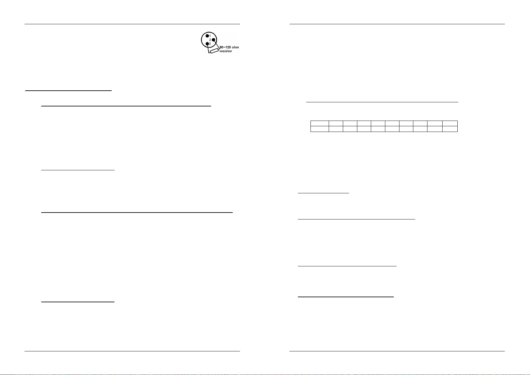
ESPAÑOL MANUAL DE FUNCIONAMIENTO
ESPAÑOL MANUAL DE FUNCIONAMIENTO
Para evitar un comportamiento anómalo de los efectos luminosos, debido a
interferencias, debe utilizar un terminador de 90Ω a 120Ω al final de la cadena.
Nunca utilice cables divisores en Y, ¡No funcionarán!
El interruptor DIP 10 debe desconectarse en todas las unidades. Cada unidad en
la cadena necesita su dirección de inicio correcta para saber desde qué
controlador DMX debe descodificar. Cuando necesite mucha energía puede utilizar varios Micro / Mini
LED Managers y suMicrostrarles la misma dirección de inicio. Consulte el capítulo anterior para saber
cómo establecer las direcciones DMX.
DIRECCIONAMIENTO DMX
Establecimiento de las direcciones DMX:
Existen 3 formas de establecer la dirección DMX de las unidades. Si utiliza las opciones de ajuste A o B,
DEBE establecer TODOS los interruptores DIP en la posición OFF (DESCONECTADA).
A. Establecimiento de direcciones DMX individuales por Micro / Mini LED Manager:
Asegúrese de que TODOS los interruptores DIP están en la posición OFF (DESCONECTADOS).
Asegúrese de que todas los cables DMX están conectados.
Conecte la primera unidad al controlador DMX universal.
Conecte todas las unidades a la red eléctrica para que estén activadas.
Establezca todos los canales DMX en su controlador DMX a cero (valor 000).
Establezca el canal DMX, que desee asignar como dirección de inicio DMX de su Micro / Mini
LED Manager, al máximo (valor 255)
Pulse brevemente el botón “Auto DMX address” (6) en el Micro / Mini LED Manager.
Si desea establecer otro unidad a la misma dirección de inicio DMX, pulse simplemente su botón
“Auto DMX address” (6) y recibirá la misma dirección.
¡Ya está!
Un ejemplo para aclarar las cosas:
Estableceremos la dirección de inicio DMX de un Micro / Mini LED Manager a 106:
Conecte el Micro / Mini LED Manager al controlador DMX tal y como se describe anteriormente
y asegúrese de que está activado.
Establezca todos los canales DMX en el controlador a cero (000)
Establezca el canal DMX 106 al máximo (255)
Pulse brevemente el botón “Auto DMX address” (6) en el Micro / Mini LED Manager.
¡Ya está! Ahora su Micro / Mini LED Manager tiene la dirección DMX 106.
B. Direccionamiento DMX automático, comenzando desde cualquier dirección de inicio dada:
Para ahorrar tiempo (imagínese el tiempo que lleva establecer los interruptores DIP de 16
unidades…) puede establecer las direcciones DMX de todas las unidades en la cadena DMX
pulsando un botón. No es necesario calcular la dirección de inicio de cada unidad individual, esto se
hace por usted.
Asegúrese de que TODOS los interruptores DIP están en la posición OFF (DESCONECTADOS).
Asegúrese de que todas los cables DMX están conectados.
Conecte la primera unidad al controlador DMX universal.
Conecte todas las unidades a la red eléctrica para que estén activadas.
Establezca todos los canales DMX en su controlador DMX a cero (valor 000).
Establezca el canal DMX, que desee asignar como dirección de inicio DMX de su Micro / Mini
LED Manager, al máximo (valor 255)
Pulse el botón “Auto DMX address” (6) en el primer Micro / Mini LED Manager de la cadena
durante unos 5 segundos.
¡Ya está! El primer Micro / Mini LED Manager en la cadena recibirá la dirección de inicio DMX
que ha seleccionado y calculará y programará automáticamente las direcciones DMX de todas las
demás direcciones en la cadena.
Un ejemplo para aclarar las cosas:
Queremos establecer las direcciones DMX de 16 unidades, la dirección de inicio DMX del primer
Micro / Mini LED Manager debe ser 202:
Conecte todos los Micro / Mini LED Manager al controlador DMX tal y como se describe
anteriormente y asegúrese de que están activados.
Establezca todos los canales DMX en el controlador a cero (000)
Establezca el canal DMX 202 al máximo (255)
Pulse el botón “Auto DMX address” (6) en el primer Micro / Mini LED Manager de la cadena
durante unos 5 segundos.
¡Ya está! El primer Micro / Mini LED Manager en la cadena recibirá la dirección de inicio DMX
202 que ha seleccionado y calculará y programará automáticamente las direcciones DMX de
todas las demás direcciones en la cadena. esto significa que el segundo Micro / Mini LED
Manager recibe automáticamente la dirección 206, el tercero la dirección 210, …, hasta que el
Micro / Mini LED Manager 16 que recibe automáticamente la dirección de inicio 262.
Acaba de programar 16 Micro / Mini LED Manager s en 10 segundos.
Observación: puede mezclar la unidades con otros efectos que no tengan la opción de
direccionamiento automático DMX. En este caso, debe establecer las direcciones DMX de estos
efectos DMX manualmente. Usted también puede mezclar el Micro / Mini LED Manager con otros
productos LED de JB Systems que incorporen el direccionamiento DMX automatico. Estos también
recibirán automáticamente sus direcciones DMX
C. Ajuste de las DIRECCIONES- DMX con los commutadores DIP switches:
Esto es el método de dirección tradicional, este método debería ser utilizado con el pequeñito
dimerizadór LED WALL DIMMER.
Los primeros 9 interruptores DIP corresponden a cierto valor DMX:
DIP #1 #2 #3 #4 #5 #6 #7 #8 #9
Valor 1 2 4 8 16 32 64 128 256
Puede combinar los valores de estos interruptores para obtener una dirección de inicio entre 1 y
512:
Dirección de inicio = 01 interruptor 1=ON valores: 1
Dirección de inicio = 05 interruptor 1+3=ON valores: 1+4 = 5
Dirección de inicio = 09 interruptor 1+4=ON valores: 1+8 = 9
Dirección de inicio = 13 interruptor 1+3+4=ON valores: 1+4+8 = 13
…
Dirección de inicio = 62 interruptor 2+3+4+5+6=ON valores: 2+4+8+16+32
INSTRUCCIONES DE FUNCIONAMIENTO
A. 1 unidad independiente:
Conecte los proyectores LED al Micro / Mini LED Manager tal y como se indica en los capítulos
anteriores.
Encienda la unidad y consulte el capítulo “AJUSTES DE INTERRUPTORES DIP” para familiarizarse
con las varias funciones de los atenuadores y botones.
B. Dos o más unidades en configuración maestra/esclava:
Conecte los proyectores LED al Micro / Mini LED Manager tal y como se indica en los capítulos
anteriores.
Conecte las unidades las unas con las otras tal y como se explica en el capítulo sobre instalaciones
eléctricas.
Encienda los Micro / Mini LED Managers. Sólo podrá utilizar los controles en la unidad maestra, los
controles en las unidades esclavas están deshabilitados. Consulte el capítulo “AJUSTES DE LOS
INTERRUPTORES DIP” para familiarizarse con las varias funciones de los atenuadores y botones en
la unidad maestra.
C. Conecte el LEDCON-02 para el control remoto:
En la mayoría de los casos el MICRO / MINI LED MANAGER se instalará en la pared, cerca de los
proyectores LED. Si desea acceder fácilmente a sus funciones, puede conectar los controles remotos
LEDCON-02 al (primer) Micro / Mini LED Manager. Las otras conexiones son idénticas a aquellas en las
configuraciones en modo maestro/esclavo o independiente. ¡No olvide de realizar la dirección
automática sobre el LEDCON-02!
D. Control mediante controlador DMX universal:
Conecte los proyectores LED al Micro / Mini LED Manager tal y como se indica en los capítulos
anteriores.
Conecte el Micro / Mini LED Manager con otros aparatos DMX en la cadena DMX.
Encienda todas las unidades y establezca las direcciones DMX correctas. (no olvide establecer el
interruptor DIP 10 en OFF (DESCONECTADO))
Encienda su controlador universal DMX y consulte la tabla DMX de abajo para controlar los Micro /
Mini LED Managers conectados:
JB SYSTEMS
®
45/57 MICRO/MINI LED MANAGER Mk2
JB SYSTEMS
®
46/57 MICRO/MINI LED MANAGER Mk2
Page 26

ESPAÑOL MANUAL DE FUNCIONAMIENTO
ESPECIFICACIONES
Entrada de alimentación: AC 100 ~ 250V (50Hz/60Hz)
Voltaje de salida para los LEDs: CA 24V ánodo común
Alimentación de salida para los LEDs: Micro LED Manager: 1x 50 W máx.
o Rojo 16W ~ 17W máx.
o Verde 16W ~ 17W máx.
o Azul 16W ~ 17W máx.
Mini LED Manager Mk2: 1x 100 W máx.
o Rojo 33W máx.
o Verde 33W máx.
o Azul 33W máx.
Conexiones DMX: 3 pines XLR (DMX-512 estándar)
Canales DMX: 4 (CH1: rojo, CH2: verde, CH3:azul, CH4:regulador de
intensidad luminosa/estroboscópica)
Entrada de audio: micrófono interno
Tamaño: Consulte el gráfico en la última página
Peso: 1,00kg (Micro LED Manager)
1,70kg (Mini LED Manager Mk2)
Toda la información está sujeta a cambios sin previo aviso
Puede descargar la última versión de este manual de usuario en nuestra página Web:
www.beglec.com
PORTUGUÊS MANUAL DO UTILIZADOR
MANUAL DO UTILIZADOR
Obrigado por ter adquirido este produto da JB Systems. De modo a tirar total proveito das possibilidades
deste produto, por favor leia este manual com atenção.
CARACTERÍSTICAS
Esta unidade está protegida contra interferências rádio. Este produto cumpre as exigências impostas pelas
presentes directivas nacionais e europeias. A conformidade deste produto foi comprovada e as declarações
e documentos relevantes foram efectuados pelo fabricante
Fonte de alimentação extremamente versátil para todos os tipos de projectores passivos RGB LED.
Diferentes modos de funcionamento autónomo:
Modo Fixed color: Acesso instantâneo a 16 cores predefinidas
Modo Auto chase: 16 diferentes sequências de cor com 8 velocidades diferentes.
Modo Sound chase: 16 diferentes sequências de cor com activação áudio
Modo Fade chase: 16 diferentes sequências de cor alternando suavemente a 8 velocidades diferentes
Qualquer interruptor parede pode ser usado para ligar/desligar a saída, mesmo em modo DMX!
Todas as funções podem ser controladas:
Directamente no MICRO / MINI LED MANAGER
Com um LED W ALL DIMMER opcional (interface especial)
Com um controlo remoto opcional LEDCON-02.
Com um MICRO / MINI LED MANAGER de 300Watt
Com qualquer controlador DMX standard
Vários Micro LED-Managers podem ser utilizados em modo Master/slave para criar configurações muito
potentes e altamente sincronizadas.
Micro LED Manager: Saída de 50Watt 24Vdc. (R+G+B) com protecção de curto-circuitos
Mini LED Manager Mk2: Saída de 100W att 24Vdc. (R+G+B) com protecção de curto-circuitos
Necessários 4 canais DMX: Ch1=red, Ch2=green, Ch3=Blue, Ch4=Dimmer/strobe.
Estrutura preparada para instalação fácil em parede.
Sem ventoinha de arrefecimento: completamente silencioso!
ANTES DE UTILIZAR
Certifique-se que a caixa contém os seguintes artigos:
MICRO LED MANAGER
Cabo de alimentação ou Mini LED Manager Mk2
Cabo de conversão de saída
Manual do utilizador
Algumas instruções importantes:
Antes de utilizar esta unidade verifique se existem danos provocados durante o transporte. Caso existam
danos aparentes, não utilize a unidade e contacte o seu revendedor.
Importante: Esta unidade deixou a nossa fábrica em perfeitas condições e devidamente embalada. É
imprescindível que o utilizador siga as instruções de segurança e avisos descritos neste manual.
Quaisquer danos provocados por utilização incorrecta não serão cobertos pela garantia. O revendedor
não será responsável por quaisquer danos ou problemas causados pelo incumprimento das instruções
deste manual.
Guarde este manual num local seguro para consulta futura. Caso venda esta unidade, forneça este
manual.
Proteja o ambiente. Recicle o material desta embalagem.
JB SYSTEMS
®
47/57 MICRO/MINI LED MANAGER Mk2
JB SYSTEMS
®
48/57 MICRO/MINI LED MANAGER Mk2
Page 27

PORTUGUÊS MANUAL DO UTILIZADOR
PORTUGUÊS MANUAL DO UTILIZADOR
INSTRUÇÕES DE SEGURANÇA:
CAUTION
O símbolo composto por um triângulo equilátero com um relâmpago no interior alerta para a
presença de voltagem perigosa não isolada no interior do produto que poderá constituir risco
de choque eléctrico.
O símbolo composto por um triângulo equilátero com um ponto de exclamação alerta o
utilizador para a presença de instruções importantes de utilização e manutenção do produto.
Este símbolo significa: utilização unicamente em espaços fechados
Este símbolo significa: Leia instruções
Este símbolo significa: Mecanismo de controlo da lâmpada
De modo a evitar risco de fogo ou choque eléctrico, não exponha este produto a chuva ou humidade.
De forma a evitar a formação de condensação no interior da unidade, ao transportá-la para ambiente
quente aguarde algum tempo de modo a que haja uma ambientação à temperatura. A condensação
poderá afectar o desempenho da unidade ou até danificá-la.
Esta unidade destina-se unicamente a utilização em espaços fechados.
Não introduza objectos de metal nem verta líquidos no interior do produto, correrá risco de choque
eléctrico ou poderá danificar o produto. Caso algum objecto estranho entre em contacto com o interior da
unidade, desligue-a de imediato da corrente.
Não coloque chamas descobertas (tais como velas acesas) sobre a unidade.
Não cubra os orifícios de ventilação ou a unidade poderá sobreaquecer.
Evite locais com poeiras. Limpe a unidade regularmente.
Mantenha esta unidade fora do alcance das crianças.
Esta unidade deverá ser operada unicamente por pessoas experientes.
Temperatura ambiente de funcionamento máxima é de 40ºC. Não utilize esta unidade a temperaturas
ambientes mais elevadas.
Desligue sempre a unidade da corrente quando não a utilizar durante longos períodos de tempo ou antes
de efectuar manutenção.
A instalação eléctrica deve ser efectuada unicamente por pessoal qualificado, cumprindo os regulamentos
de segurança em instalações eléctricas e mecânicas do seu país.
Certifique-se que a voltagem a utilizar não é superior à voltagem indicada no painel traseiro da unidade.
A tomada de corrente deverá permanecer acessível para que a unidade possa ser desligada da corrente.
O cabo de alimentação deverá estar sempre em perfeitas condições. Desligue a unidade e substitua
imediatamente o cabo caso este apresente algum dano. Deverá ser substituído pelo fabricante, pelo
agente autorizado ou pessoal qualificado de modo a evitar um acidente.
Nunca permita que este cabo entre em contacto com outros cabos!
O MICRO / MINI LED MANAGER deve ser ligado à terra de forma a cumprir com os regulamentos de
segurança.
De forma a não correr risco de choque eléctrico não abra a cobertura da unidade. À excepção do fusível,
não existem peças que possam ser substituídas pelo utilizador.
Nunca repare um fusível nem tente operar a unidade sem fusível. Substitua sempre um fusível danificado
por outro com as mesmas características!
Em caso de problemas sérios de funcionamento, interrompa a utilização da unidade e contacte
imediatamente o seu revendedor.
Caso seja necessário transportar a unidade utilize a embalagem original.
Por motivos de segurança, são proibidas quaisquer alterações não autorizadas à unidade.
ATENÇÃO: De forma a evitar o risco de choque eléctrico,
não remova peças da unidade. Não tente fazer
reparações. Contacte pessoal qualificado
LIMPEZA DO APARELHO
Utilize um pano limpo ligeiramente humedecido em água. Evite introduzir água dentro da unidade. Não
utilize líquidos voláteis como benzeno ou diluente, irá danificar a unidade.
Uma vez que esta unidade utilize uma ventoinha, o seu interior deverá ser limpo anualmente utilizando-se
um aparelho de limpeza a vácuo ou um compressor.
Atenção: Aconselhamos vivamente que a limpeza interna seja executada por pessoal qualificado!
FUNÇÕES
MICRO LED MANAGER
MINI LED MANAGER Mk2
1. MICROFONE INTERNO: Usado para sequências activadas por som.
2. ENTRADA DMX: Conector XLR macho de 3 pin utilizado para ligar cabos DMX universais. Esta entrada
recebe instruções de um controlador DMX ou de outro Micro / Mini LED Manager quando utilizado do
modo master/slave.
3. SAÍDA DMX: Conector XLR fêmea de 3 pinos usado para conectar o Micro LED-Manager com o
próximo dispositivo DMX na corrente ou com outro Micro LED-Manager quando usado em modo
master/slave.O Micro / Mini LED Manager também pode ser utilizado para controlar outros projectores
LED como por exemplo o “LED PAR56/64”
4. LED POWER ON: Usado para verificar se o Micro / Mini LED Manager está ligado á corrente.
5. INTERRUPTORES DIP: Quando usado em modo DMX (DIP10 = OFF) pode definir o endereço DMX
inicial da unidade. Quando utilizado no modo (master, DIP10 = ON), pode utilizar os interruptores DIP
para ajustar diferentes opções pré programadas.
6. BOTÃO CONFIGURAÇÃO AUTO DMX: veja mais adiante para aprender como configurar facilmente o
endereço DMX
7. TERMINAIS DE SAÍDA: Usado para conectar diferentes projectores LED 24Vdc ânodo comum. Pode
conectar qualquer cabo eléctrico de 4 pólos para conectar os projectores LED a esta saída. De qualquer
forma, para tornar a vida mais fácil sugerimos usar o cabo especial CCM-50 (rolo=50m). Os fios neste
cabo correspondem ás cores dos LEDs
8. ENTRADA PARA INTERRUPTOR ANALÓGICO: Usado para conectar qualquer interruptor analógico
externo. Este interruptor externo pode ser usado para ligar/desligar a saída geral do Micro / Mini LED
Manager. (blackout externo) Ver adiante para mais informações como conectar o interruptor
analógico.
JB SYSTEMS
®
49/57 MICRO/MINI LED MANAGER Mk2
JB SYSTEMS
®
50/57 MICRO/MINI LED MANAGER Mk2
Page 28

PORTUGUÊS MANUAL DO UTILIZADOR
Configuração DIP
Modo Auto/Transição
Função
DIP10 = OFF
DMX
/ Operação Slave
DIP10 = ON
Operação Master
(stand-alone
)
PORTUGUÊS MANUAL DO UTILIZADOR
9. ENTRADA WALL DIMMER: Usado para conectar o nosso LED WALL DIMMER, um pequeno
controlador de LEDs que encaixa em qualquer caixa eléctrica de parede”. Ver adiante para mais
informação como conectar o LED WALL DIMMER.
10. ENTRADA CORRENTE: Com ficha IEC, conecte o cabo de alimentação fornecido aqui.
11. LED STATUS: Mostra o estado da unidade. Deverá piscar quando sinal DMX é detectado.
CONFIGURAÇÕES DOS INTERRUPTORES DIP
Interruptores Dip 10:
Configuração DIP
Pode usar a função de configuração automática de DMX (ver adiante) ou através dos
tradicionais interruptores DIP
Use os interruptores Dip 1~9 para definir o modo, velocidade, padrões, cor fixa, cor…etc
funções.
Mais abaixo cada uma destas funções é explicada em detalhe.
Interruptores Dip 1&2: Modo (Som/auto/transição/cor fixa):
Configuração DIP MODO
SOUND: Microfone interno activa os padrões seleccionados.
AUTO: Os padrões seleccionados correm automaticamente á velocidade desejada
FADE: As cores do padrão seleccionado desvanecem á velocidade desejada
COR FIXA: Utilize os interruptores DIP 6,7,8 & 9 para seleccionar as cores desejadas
Interruptores Dip 3,4 & 5:Velocidade (de rápido a lento):
Velocidade 1 Rápido
Velocidade 2
Velocidade 3
Velocidade 4
Velocidade 5
Velocidade 6
Velocidade 7
Velocidade 8
Interruptores Dip 6,7 ,8 & 9: Sequência & Cor:
Configuração DIP MODO SOM & AUTO MODO COR FIXA
Sequência Standard Branco
Sequência Brilhante Vermelho
Sequência modo Laranja
Sequência spectrum aleatória Âmbar
Sequência Spectrum Amarelo
Sequência Dinâmica Amarelo claro
Lento
Sequência Vermelho – Cyan Verde maçã
Sequência Verde – Púrpura Verde-claro
Sequência Azul – Vermelho Verde
Sequência Amarelo – Azul Ciano
Sequência Vermelho – Verde Azul
Sequência Amarelo – Verde Azul-escuro
Sequência Cyan – Laranja Roxo
Sequência Verde – Púrpura claro Roxo claro
Sequência Vermelho – Amarelo Magenta
Sequência Amarelo Dourado – Azul Rosa
INSTALAÇÃO ELÉCTRICA
A instalação eléctrica deverá ser executada apenas por pessoal qualificado e de acordo com as
regulamentações de segurança eléctrica e mecânica do seu país.
Como conectar projectores LED à saída da unidade:
Importante: Desligue o Micro / Mini LED Manager antes de instalar os projectores LED! A carga
total máxima do Micro Led Manager é de 50W, distribuídos pelas 3 cores: cada uma das 3 cores
tem uma carga máxima de 16W ~ 17W! A carga total máxima do Mini Led Manager Mk2 é de 100W,
distribuídos pelas 3 cores: cada uma das 3 cores tem uma carga máxima de 33W!
Podem-se ligar 2 tipos diferentes de projectores LED passivos:
A. Projectores LED com conector especial de 4 pin (ex. LED STRIP):
Use o cabo de conversão
fornecido e conecte os 4 fios
dos projectores LED aos 4
terminais correspondentes do
MICRO / MINI LED MANAGER.
Fixe todos os projectores correctamente e ligue-os em cadeia através dos cabos de entrada/saída até
que atinja a carga máxima permitida. Certifique-se de apertar o anel de plástico do conector.
B. Projectores LED com fios abertos (ex. LED GROUND LIGHT):
Simplesmente conecte os fios coloridos aos terminais correspondentes no LED MICRO MANAGER.
Assegure-se que não excede a carga máxima permitida:
Fio branco: Este é o cabo terra (ânodo)
Fio vermelho: Este é a potência para os LEDs vermelhos
Fio verde: Este é a potência para os LEDs verdes
Fio azul: Este é a potência para os LEDs azuis
Nota: As saídas para os projectores LED são protegidas contra
curto-circuitos. Contudo quando ocorre um curto-circuito tem de
ser reiniciado: desligue o Micro / Mini LED Manager cerca de
10 segundos da corrente e ligue-o outra vez.
Ligando um interruptor analógico externo para blackout:
Usando um interruptor normal de ligar/desligar, pode colocar a
saída do Micro / Mini LED Manager em modo blackout, mesmo
que esteja a ser controlado por DMX: por exemplo pode usar
um “interruptor de parede” para ligar/desligar o Micro / Mini
LED Manager a qualquer momento!
Conectado ao interruptor de parede na posição OFF
(contactos abertos): Saída Ligada
Conectado ao interruptor de parede na posição ON
(contactos fechados): Saída Desligada
JB SYSTEMS
®
51/57 MICRO/MINI LED MANAGER Mk2
JB SYSTEMS
®
52/57 MICRO/MINI LED MANAGER Mk2
Page 29

PORTUGUÊS MANUAL DO UTILIZADOR
PORTUGUÊS MANUAL DO UTILIZADOR
Conectando o LED WALL DIMMER opcional:
O LED W ALL DIMMER é um pequeno controlador fácil de
usar que pode ser instalado em qualquer caixa de ligações
de parede standard. Este controlador pode ser conectado
directamente ao Micro / Mini LED Manager. Os 0V & +12V
deverão ser conectados através de um cabo normal de 2
fios. O sinal DMX deverá ser ligado usando um cabo DMX
balanceado de boa qualidade com bom isolamento.
Nota 1: O Micro / Mini LED Manager deverá ser definido no
endereço DMX em 001, usando os tradicionais interruptores
DIP (ver “Configuração DMX para aprender a fazer isto)
Nota 2: Se desejar controlar mais de 1 (Micro) LED Manager,
simplesmente conecte os LED Managers através das
entradas e saídas de sinal e coloque todos os endereços
DMX para 001.
Instalação eléctrica em modo Master/slave:
Terá que ligar em cadeia as entradas/saídas DMX de 2
ou mais unidades com um cabo balanceado de boa qualidade.
Coloque a unidade com a entrada DMX livre em modo Master, as outras unidades mudam
automaticamente para modo slave. Os interruptores DIP nas unidades slave ficam desactivados.
Instalação eléctrica em modo Master/slave com controlo remoto LEDCON-02:
Terá que ligar em cadeia as entradas/saídas DMX de 1 ou mais unidades com a saída do controlo
remoto LEDCON-02 usando um cabo balanceado de boa qualidade
O controlador remoto LEDCON-02 será utilizado para controlar todos os slaves. Os Micro / Mini LED
Managers entram automaticamente em modo slave. Os interruptores DIP nas unidades slave ficam
desactivados.
Instalação eléctrica em modo DMX:
O protocolo DMX é um sinal de alta velocidade usado para controlar equipamento inteligente de
iluminação. Terá de ligar em cadeia o seu controlador DMX e todas as unidades conectadas com um
cabo balanceado de boa qualidade
Para prevenir comportamento estranho dos efeitos de luz, devido a interferências,
tem de usar um finalizador de 90Ω a 120Ω no final da cadeia. Nunca use cabos
divididos em Y, simplesmente não funcionam!
Interruptor DIP 10 deverá estar definido para OFF em todas as unidades. Cada
unidade na cadeia precisa do seu endereço inicial para saber quais os comandos
do controlador DMX a descodificar. Quando precisar de muita potência pode usar vários Micro / Mini
LED Managers e dar-lhes o mesmo endereço inicial. Veja a secção anterior e veja como definir os
endereços
CONFIGURAÇÃO DMX
Como definir os endereços DMX:
Existem 3 maneiras de definir os endereços DMX das unidades. Se usar as opções de configuração A, B
tem de colocar todos os interruptores na posição OFF
A. Configurar canal DMX individualmente por Micro / Mini LED Manager:
Verifique que todos os interruptores DIP estão na posição OFF!
Verifique que todos os cabos DMX de todas as unidades estão ligados.
Conecte a primeira unidade a um controlador DMX universal.
Conecte todas as unidades á corrente para que estas liguem.
Defina todos os canais DMX no seu controlador a zero (valor 000)
Defina o canal DMX, que pretende atribuir como endereço inicial DMX ao vosso Micro / Mini LED
Manager, total máximo (valor 255)
Pressione o botão “Auto configuração DMX” (6) no vosso Micro / Mini LED Manager
Se desejar definir outro unidade no mesmo canal inicial DMX, simplesmente pressione o seu
botão “Auto configuração DMX” (6) e este irá receber o mesmo endereço.
Feito!
Um exemplo para esclarecer:
Iremos definir o endereço inicial DMX de um Micro / Mini LED Manager para 106:
Conecte o Micro / Mini LED Manager a um controlador DMX como descrito acima e verifique
que tudo está ligado
Coloque todos os canais DMX do controlador DMX para zero (000)
Agora defina o canal DMX 106 para o máximo (255)
Pressione o botão “Auto configuração DMX” (6) no Micro / Mini LED Manager.
Feito! O seu Micro / Mini LED Manager agora tem o endereço DMX 106!
B. Configuração DMX automática, começando a partir de um endereço inicial dado:
Para poupar muito tempo (imagine o tempo que demora a definir os interruptores DIP de 16
unidades…) pode definir os endereços DMX de todas as unidades na cadeia DMX pressionando
apenas um botão. Sem necessidade de calcular o endereço inicial de cada unidade individual, isto
será feito para si!
Verifique que todos os interruptores DIP estão na posição OFF!
Verifique que todos os cabos DMX de todas as unidades estão ligados.
Conecte a primeira unidade a um controlador DMX universal.
Conecte todas as unidades á corrente para que estas liguem.
Coloque todos os canais do controlador DMX para zero (000).
Defina o canal DMX, que pretende atribuir como endereço inicial no seu Micro / Mini LED
Manager, total máximo (valor 255)
Pressione o botão “Auto configuração DMX” no primeiro Micro / Mini LED Manager da cadeia
cerca de 5 segundos.
Feito! O primeiro Micro / Mini LED Manager na cadeia irá receber o endereço inicial DMX que
escolher e irá calcular automaticamente e programar os endereços DMX de todas as outras
unidades da cadeia DMX!
Um exemplo para esclarecer:
Queremos definir o endereço DMX de 16 unidades, o endereço inicial DMX do primeiro Micro /
Mini LED Manager tem de ser 202:
Conecte todos os Micro / Mini LED Manager a um controlador DMX como descrito acima e
verifique que estão todos ligados á corrente.
Coloque todos os canais do controlador DMX para zero (000).
Agora coloque o canal DMX 202 no máximo (255)
JB SYSTEMS
®
53/57 MICRO/MINI LED MANAGER Mk2
JB SYSTEMS
®
54/57 MICRO/MINI LED MANAGER Mk2
Page 30

PORTUGUÊS MANUAL DO UTILIZADOR
Pressione o botão “Auto configuração DMX” no primeiro Micro / Mini LED Manager da cadeia
cerca de 5 seg.
Feito! O primeiro Micro / Mini LED Manager na cadeia irá receber o endereço inicial DMX 202
e irá calcular automaticamente e programas os endereços DMX de todas as outras unidades na
cadeia DMX!
Isto significa que o 2º Micro / Mini LED Manager automaticamente recebe o endereço 206, o 3º
tem o endereço 210, …, até que o 16º Micro / Mini LED Manager que automaticamente recebe
o endereço inicial 262.
Acabou de programar 16 Micro / Mini LED Manager, isto demorou cerca de 10 segundos!!!
Atenção: Pode misturar estas unidades com outros efeitos DMX que não tenham a opção “Auto
Configuração DMX”. Neste caso terá de definir os endereços DMX destes efeitos DMX
manualmente! Pode também misturar o Micro / Mini LED Manager com outros produtos LED da JB
Systems que tenham a função auto DMX. Irão receber automaticamente os seus endereços DMX
C. Definir o endereço DMX usando os interruptores DIP:
Este é o método tradicional de configuração. Este método deverá ser usado quando usado com o
LED WALL DIMMER.
Os primeiros 9 interruptores DIP correspondem a um certo valor DMX:
DIP #1 #2 #3 #4 #5 #6 #7 #8 #9
Valor 1 2 4 8 16 32 64 128 256
valores destes interruptores para obter qualquer endereço inicial entre 1 e 512:
Endereço Inic. = 01 interr. 1=ON valores: 1
Endereço Inic. = 05 interr. 1+3=ON valores: 1+4 = 5
Endereço Inic. = 09 interr. 1+4=ON valores: 1+8 = 9
Endereço Inic. = 13 interr. 1+3+4=ON valores: 1+4+8 = 13
…
Endereço Inic. = 62 interr. 2+3+4+5+6=ON valores: 2+4+8+16+32 = 62
Pode combinar os
INSTRUÇÕES DE UTILIZAÇÃO
A. Uma unidade em modo Autónomo:
Ligue os projectores LED ao MICRO / MINI LED MANAGER como indicado nas secções anteriores.
Ligue a unidade e veja a secção “Configurações dos interruptores DIP” para se familiarizar com as
várias funções dos botões e faders.
B. Duas ou mais unidades em modo master/slave:
Ligue os projectores LED ao MICRO / MINI LED MANAGER como indicado nas secções anteriores.
Ligue as unidades entre si tal como explicado na secção sobre instalação eléctrica. (não é necessário
configurar um endereço DMX!)
Ligue os Micro / Mini LED Managers. Apenas poderá utilizar os controlos da unidade Master, os
controlos das restantes estão desactivados veja a secção “Configurações dos interruptores DIP” para
se familiarizar com as várias funções dos botões e faders da unidade Master.
C. Ligado ao controlador opcional LEDCON-02 para controlo remoto:
Na maior parte dos casos o MICRO / MINI LED MANAGER será instalado numa parede, junto aos
projectores LED. Se desejar ter acesso fácil ás suas funções, pode ligar o controlador remoto LEDCON02 ao (primeiro) MICRO / MINI LED MANAGER. As outras ligações são idênticas ás das configurações
de autónomo e de master/slave. Não se esqueça de efectuar a função configuração automática
DMX no LEDCON-02!
D. Controlado através de um controlador DMX universal:
Ligue os projectores LED ao MICRO / MINI LED MANAGER como indicado nas secções anteriores.
Conecte o(s) MICRO / MINI LED MANAGER(s) com todos os outros dispositivos DMX na cadeia
DMX.
Ligue todas as unidades e configure os endereços DMX apropriados. (não se esqueça de colocar o
interruptor DIP 10 em OFF)
Ligue o seu controlador DMX universal e veja a tabela DMX abaixo indicada para controlar os Micro /
Mini LED Managers conectados:
PORTUGUÊS MANUAL DO UTILIZADOR
ESPECIFICAÇÕES
Entrada de alimentação: AC 100 ~ 250V (50Hz/60Hz)
Voltagem de saída para LEDs: DC 24V ânodo comum
Potência de saída para LEDs: Micro LED Manager: 1x 50W max.
o Vermelho: 16W ~ 17W max.
o Verde: 16W ~ 17W max.
o Azul: 16W ~ 17W max.
Mini LED Manager Mk2: 1x 100W max.
o Vermelho: 33W max.
o Verde: 33W max.
o Azul: 33W max.
Ligações DMX: XLR 3 pinos (DMX-512 standard)
Canais DMX: 4 (CH1: vermelho, CH2: verde, CH3:azul, CH4:dimmer/strobe)
Entrada Áudio: microfone interno
Tamanho: Ver imagem sobre a última página
Peso: 1,00kg (Micro LED Manager)
1,70kg (Mini LED Manager Mk2)
Estas informações estão sujeitas a alterações sem aviso prévio
Pode fazer download da versão mais recente deste manual no nosso site: www.beglec.com
JB SYSTEMS
®
55/57 MICRO/MINI LED MANAGER Mk2
JB SYSTEMS
®
56/57 MICRO/MINI LED MANAGER Mk2
Page 31

PORTUGUÊS MANUAL DO UTILIZADOR
MINI LED MANAGER Mk2 MICRO LED MANAGER
JB SYSTEMS
®
57/57 MICRO/MINI LED MANAGER Mk2
 Loading...