

Page 1
Page 2
12. Use only with the cart, stand, tripod, bracket, or table specified by the manufacturer, or sold with the apparatus.When a cart is used, use caution when moving the cart/apparatus
combination to avoid injury from tip-over.
IMPORTANT SAFETY INSTRUCTIONS
1. Read these instructions.
2. Keep these instructions.
3. Heed all warnings.
4. Follow all instructions.
5. Do not use this apparatus near water.
6. Clean only with dry cloth.
7. Do not block any ventilation openings. Install in accordance with the manufacturer’s instructions.
8. Do not install near any heat sources such as radiators, heat registers, stoves, or other apparatus, (including amplifiers) that produce heat.
9. Do not defeat the safety purpose of the polarized or grounding-type plug. A polarized plug has two blades with one wider than the other. A grounding-type plug has two blades and a third
grounding prong.The wide blade or the third prong are provided for your safety. If the provided plug does not fit into your outlet, consult an electrician for replacement of the obsolete outlet.
10. Protect the power cord from being walked on or pinched particularly at plugs, convenience receptacles, and the point where they exit from the apparatus.
11. Only use attachments/accessories specified by the manufacturer.
This triangle, which appears on your component,
alerts you to the presence of uninsulated,
dangerous voltage inside the enclosure -
voltage that may be sufficient to
constitute a risk of shock.
CAUTION
RISK OF ELECTRIC SHOCK
DO NOT OPEN
This triangle, which appears on your component,
alerts you to important operating and
maintenance instructions in this
accompanying literature.
To reduce the risk of fire or electric shock, do not expose this apparatus to rain or moisture.
WARNING
• Refer to the manufacturer's operating instructions for power requirements.Be advised that different operating voltages may require the use of a different line cord and/or attachment plug.
• Do not install the unit in an unventilated rack, or directly above heat producing equipment such as power amplifiers.Obser ve the maximum ambient operating temperature listed in the product
specification.
•Never attach audio power amplifier outputs directly to any of the unit's connectors.
This equipment has been tested and found to comply with the limits for a Class B digital device, pursuant to Part 15 of FCC Rules.These limits are designed to provide reasonable protection against
harmful interference in a residential installation.This equipment generates, uses, and radiates radio frequency energy and, if not installed and used in accordance with the instructions, may cause
harmful interference to radio or television reception, which can be determined by turning the equipment off and on.The user is encouraged to try to correct the interference by one or more of the
following measures:
• Reorient or relocate the receiving antenna. • Connect the equipment into an outlet on a circuit different from that to which the receiver is connected.
• Increase the separation between the equipment and the receiver. • Consult the dealer or an experienced radio/television technician for help.
13. Unplug this apparatus during lightning storms or when unused for long periods of time.
14. Refer all servicing to qualified service personnel.Servicing is required when the apparatus has been damaged in any way, such as when a power-supply cord or plug is damaged, liquid has been
spilled or objects have fallen into the apparatus, the apparatus has been exposed to rain or moisture, does not operate normally, or has been dropped.
Page 3

Harman Consumer Group, Inc.
8500 Balboa Park
Northridge, CA 91329
250 Crossways Park
Woodbury, NY 11797
516-255-4JBL
www.jbl.com
JBL, Lexicon, Logic 7 and the L7 logos are registered trademarks of Harman International Industries, Incorporated.
Dolby, Pro Logic, and the double-D symbol are registered trademarks of Dolby Laboratories, Inc.
DTS, DTS-ES, and Neo:6 are registered trademarks of DTS, Inc. and DTS 96/24 is a trademark of DTS, Inc.
HDMI, the HDMI logo and High-Definition Multimedia Interface are trademarks or registered trademarks of HDMI Licensing LLC.
Macrovision is a registered trademark of Macrovision Corporation. All rights reserved.
SACD is a trademark of Sony Corporation.
SHARC is a registered trademark of Analog Devices, Inc.
Surround EX is a jointly developed technology of THX and Dolby Laboratories, and is a trademark of Dolby Laboratories. Used under
authorization.
THX is a registered trademark of THX Ltd. Ultra2 is a trademark of THX Ltd. All rights reserved.
TOSLINK is a registered trademark of Toshiba Corporation.
© 2006 Harman International Industries, Incorporated. All rights reserved.
Part No. 070-18567 | Rev 0 | 11/06
Features, specifications, and appearance are subject to change without notice.
Page 4
Introduction JBL
DOCUMENTATION CONVENTIONS
This document contains general safety, installation and operation instructions for the SDP-40HD Digital Surround Processor/Controller. It is
important to read this user guide before attempting to use the product. Pay particular attention to safety instructions.
The following symbols are used in the document:
WARNING
CAUTION!
Note:
Appears on the component to indicate the presence of uninsulated, dangerous voltage inside
the enclosu
constitute a risk of shock.
Appears on the component to indicate important operating and maintenance instructions in
the accompanying literature.
Calls attention to a procedure, practice, condition or the like that, if not correctly performed
or adhered to, could result in injury or death.
Calls attention to a procedure, practice, condition or the like that, if not correctly performed
or adhered to, could result in damage or
destruction to part or all of the product.
Calls attention to information that is essential to
highlight.
re – voltage that may be sufficient to
INPUTSSETUP
Represents a menu path. The menu items in gray boxes must be
selected with the remote control Menu arrow to access the
menu or menu item in the black box. For example, the SETUP,
INPUTS, and DVD1 menu items must be selected to open the
DVD1 INPUT SETUP menu.
The DVD1 INPUT SETUP menu is used here as an example and will
continue to be used as an example throughout this document.
Whenever it appears, any other INPUT SETUP menu may be substituted. Likewise, whenever the DVD1 input appears as a step in a
menu path, any other input may be substituted.
DVD1
NAME
EDIT INPUT NAME
This document uses the term DTS(-ES) to indicate that DTS-ES encoding may or may not be present in the input source.
ii
Page 5

SDP-40HD Introduction
Table of Contents
Documentation Conventions........................................................ ii
Getting Started
About The SDP-40HD................................................................1-2
Highlights ............................................................................. 1-4
Product Registration ..................................................................1-5
Installation Considerations.........................................................1-5
Remote Control Battery Installation and Replacement ............... 1-6
Basic Operation
Front-Panel Overview ................................................................2-2
Rear-Panel Overview..................................................................2-5
Remote Control Overview .........................................................2-9
Operation Considerations ...................................................... 2-9
Command Bank Activation......................................................2-10
Command Matrix ............................................................... 2-11
Menu Navigation ....................................................................2-16
Main Menu ......................................................................... 2-16
Menu Item Selection ........................................................... 2-17
About the Zones ..................................................................... 2-19
Two-line Status........................................................................ 2-19
Status Menus .......................................................................... 2-20
Status Menu Level Meters ................................................... 2-21
Status Menu Descriptions .................................................... 2-22
Status Menu Parameter Descriptions ................................... 2-26
Setup
Setup ........................................................................................ 3-2
Input Setup ............................................................................... 3-3
Changing Input Names ......................................................... 3-4
Assigning HDMI, Audio and Video Input Connectors ............. 3-6
Selecting Preferred Listening Modes .................................... 3-13
Configuring Advanced Input Settings .................................. 3-19
INPUT SELECT Parameter Settings ....................................... 3-21
ZONE2 & RECORD IN Parameter Settings ........................... 3-24
Speaker Setup .........................................................................3-27
Calibrating Speaker Distances & Output Levels ....................... 3-39
Speaker Calibration Parameters ........................................... 3-39
LEVELS Calibration .............................................................. 3-40
Rear-Panel Configuration......................................................... 3-47
Display Setup .......................................................................... 3-49
On-Screen Display ............................................................... 3-51
Front-Panel Display ............................................................. 3-53
Volume Control Setup.............................................................3-54
Trigger Setup ..........................................................................3-56
Lock Options........................................................................... 3-59
Audio Controls
Audio Controls .......................................................................... 4-2
Mode Adjust
Mode Adjust ............................................................................. 5-2
Listening Mode Activation.........................................................5-2
Preferred Listening Mode Selection Parameters ..................... 5-3
Mode Buttons ....................................................................... 5-4
Mode Family Selection Buttons ............................................. 5-4
Listening Mode Descriptions ..................................................... 5-5
Listening Mode Menu Option & Parameter Descriptions......... 5-35
Mode – Parameter Relationships.............................................. 5-43
Troubleshooting & Maintenance
Troubleshooting........................................................................ 6-2
Routine Maintenance ................................................................ 6-4
Restoring Factory-default Settings ............................................. 6-5
Appendix
Specifications ............................................................................A-2
Declaration of Conformity.........................................................A-4
Menu Tree ................................................................................A-5
Installation Worksheet ............................................................A-19
iii
Page 6

Introduction JBL
iv
Page 7

1
Getting Started
About The SDP-40HD................................................................. 1-2
Highlights ................................................................................................ 1-4
Product Registration................................................................... 1-5
Installation Considerations.......................................................... 1-5
Remote Control Battery Installation ............................................ 1-6
Page 8

Getting Started JBL
ABOUT THE SDP-40HD
Thank you for purchasing the SDP-40HD Digital Controller, a
reference-quality, 12-channel audio and video control center with
independent zone monitoring to provide control of input source
selection in three zones at the same time. As flexible as it is
powerful, the SDP-40HD includes 12 inputs, each of which can be
configured and assigned to any of its 6 HDMI™ (High-Definition
Multimedia Interface™), 13 digital audio, 8 analog audio,
2 composite video, 3 S-video, or 4 component video input
connectors. The analog audio input connectors can be configured
for stereo or 5.1-channel sources.
The SDP-40HD features an HDMI interface that enables the
transmission of uncompressed digital audio and video signals
through a single connector. The SDP-40HD can pass digital video
signals of up to 720p/1080i, and multiple digital audio channels
(5.1 channels) at sample rates of up to 96kHz through the HDMI
interface. The SDP-40HD also supports the High-bandwidth Digital
Content Protection (HDCP) technology that comprises data
encryption and authentication of the partner equipment.
Beyond the HDMI connectors and standard 5.1-channel audio output
connectors, the rear panel includes stereo rear and stereo subwoofer
connectors to provide even more audio channels. All Main Zone audio
output connectors include 24-bit/96kHz D/A converters operating in
dual differential mode. In addition, the SDP-40HD includes balanced
audio output connectors for all Main Zone and Zone 2 channels.
Two RS-232 connectors are provided for serial control. One of the
connectors is for performing flash-memory software upgrades and
backing up or restoring configuration files. The other connector is
reserved for possible upgrades.
More than just an audio and video control center, the SDP-40HD
features the latest version of Harman’s critically acclaimed Logic 7®
decoding, which derives 7.1-channel output from stereo, 5.1-, and
6.1-channel sources. Unlike other decoders, Logic 7 is compatible
with all input sources and requires no special encoding. Because
the improvement it provides is clearly audible, Logic 7 decoding is
widely regarded as the finest available.
In addition to Logic 7, the SDP-40HD is also equipped with Dolby®
Digital Surround EX™, Dolby Pro Logic®, Dolby Pro Logic II, Dolby
Pro Logic IIx, DTS 96/24™, DTS NEO:6®, DTS-ES®, THX Ultra2™,
and THX Surround EX™ decoding. THX Ultra2 certification
guarantees that the SDP-40HD meets the highest THX performance
specifications.
With four 32-bit floating-point SHARC™ digital signal processing
(DSP) engines, the SDP-40HD offers unparalleled processing power.
These DSP engines perform custom processing such as Logic 7
decoding, bass enhancement, dialog enhancement, auto azimuth,
5-speaker enhancement, bass management, high-precision digital
crossovers, and tone controls. This processing is available at sample
rates up to 96kHz, with 24-bit resolution to retain top performance
from all input sources and listening modes. A fifth DSP engine is
dedicated to decoding multi-channel compressed audio sources.
High-precision 96kHz/24-bit A/D converters can be used to convert
stereo and 5.1 analog audio input signals to digital signals,
allowing the SDP-40HD to provide the benefits of precise digital
signal processing without sacrificing signal integrity.
Digital audio input signals are processed through a two-stage
phase lock loop for extremely low intrinsic jitter and high jitter
rejection. Auto azimuth technology corrects timing and level
imbalances in stereo sources, ensuring exceptionally accurate
playback of surround encoded sources. A digital audio passthrough option is available for recording digital signals with a CD
recorder or a similar component.
1-2
Page 9

SDP-40HD Getting Started
To complement its audio performance, the SDP-40HD features two
broadcast-quality video switchers. An ultra-wide bandwidth
component video switcher accepts analog component or RGB video
signals, & can pass analog high-definition (HD), enhanced-definition
(ED), and standard-definition (SD) TV signals. A composite and
S-video switcher accepts NTSC, PAL or SECAM video signals. Both
switchers are designed to pass video signals without alteration or
degradation. In addition, the SDP-40HD can convert composite and
S-video input signals to analog component video.
High-definition digital TV (HDTV) broadcasts require equipment
that can process and display digital video signals at a resolution of
either 720p or 1080i. For sources with HDMI digital video outputs,
the SDP-40HD delivers these resolutions through the HDMI output
to compatible display devices.
Analog 720p or 1080i video signals can pass through the
broadcast-quality component video switcher. In comparison, most
standard-definition (SDTV) broadcasts have a resolution of 480i.
Some DVD players and enhanced-definition (ED) digital TV
broadcasts have a 480p resolution. For digital video input sources
using an HDMI interface, the SDP-40HD delivers these resolutions
through the HDMI switcher.
Resolution is defined by the number of horizontal lines displayed
on-screen that comprise each frame of a video image. The more
lines of resolution used to create each frame of video, the greater
the detail and sharpness of the image. For example, the resolution
known as 720p refers to 720 horizontal lines of progressive video.
The resolution known as 1080i refers to 1,080 lines of interlaced
video.
An unparalleled processor, the SDP-40HD conveys the best in music
and cinema with awesome power and leading-edge technological
sophistication. Even the most demanding enthusiasts will be
impressed with its exceptional performance. The SDP-40HD is a
must-have addition for any high-quality home theater.
1-3
Page 10

Getting Started JBL
HIGHLIGHTS
• 12 channels
• 12 configurable inputs
• 3 independent zones
• 6 HDMI input connectors
• 13 digital audio input connectors,
including 6 S/PDIF coaxial, 6 S/PDIF
optical, and 1 AES/EBU
• 5.1-channel analog audio input
connector
• Balanced audio output connectors for
all Main Zone and Zone 2 channels
• Analog bypass option for stereo and
5.1-channel analog audio input
connectors
• Auto switching between digital and
analog audio input connectors
• 24-bit/192kHz D/A converters for all
Main Zone audio channels
• Stereo subwoofer connectors, and one
LFE output connector
• Manual calibration of speaker distances
and output levels
• 4 sets component video input
connectors with full HDTV compatibility
(3 RCA, 1BNC)
• 1 set BNC component video output
connectors
• 3 S-video input connectors
• 2 composite video input connectors
• Broadcast-quality video switching
• Four 32-bit DSP engines
• Separate DSP engine for decoding
compressed audio sources
• LOGIC 7 decoding
• Dolby Digital Surround EX, Dolby Pro
Logic, Dolby Pro Logic II, and Dolby Pro
Logic IIx decoding
• DTS 96/24, DTS Neo:6, and DTS-ES
(discrete and matrix) decoding
• THX Ultra2 and THX Surround EX
decoding
• THX Ultra2 Certification
• RS-232 connector for flash memory
software upgrades and configuration
backups
• 1 HDMI output connector
• 2 digital audio output connectors
• 4 composite video output connectors
(2 Main Zone, 2 Record Zone)
• 4 S-video output connectors (2 Main
Zone, 2 Record Zone)
• 3 trigger output connectors
• Rear panel IR input connector
• 4 microphone input connectors
1-4
Page 11

SDP-40HD Getting Started
PRODUCT REGISTRATION
Please register the SDP-40HD Digital Controller within 15 days of
purchase. Register online at www.jbl.com. Retain the original sales
receipt as proof of warranty coverage.
INSTALLATION CONSIDERATIONS
The SDP-40HD requires special care during installation to ensure
optimal performance. Pay particular attention to instructions below
and to other precautions that appear throughout this user guide.
DO install the SDP-40HD on a solid, flat, level surface such as a table
or shelf. The SDP-40HD can also be installed in a standard 19-inch
equipment rack using an optional rack-mount kit available from an
authorized dealer.
DO select a dry, well-ventilated location out of direct sunlight.
DO NOT expose the SDP-40HD to high temperatures, humidity,
steam, smoke, dampness or excessive dust. Avoid installing the
SDP-40HD near radiators and other heat-producing appliances.
DO NOT install the SDP-40HD near unshielded TV or FM antennas,
cable TV decoders, or other RF-emitting devices that might cause
interference.
DO NOT obstruct the front-panel IR receiver window. The remote
control must be in line of sight with the IR receiver for proper
operation.
DO NOT install the SDP-40HD on a surface that is unstable or
unable to support all four feet, unless it is installed in an
equipment rack.
DO NOT stack the SDP-40HD directly above heat-producing
equipment such as a power amplifier.
CAUTION!
Before moving the SDP-40HD, power the unit off using
the rear-panel power switch and unplug the power cord
from the wall outlet.
DO NOT place the SDP-40HD on a thick rug or carpet, or cover the
SDP-40HD with a cloth, as this might prevent proper cooling.
DO NOT place the SDP-40HD on a window sill or any location
exposed to direct sunlight.
1-5
Page 12
Getting Started JBL
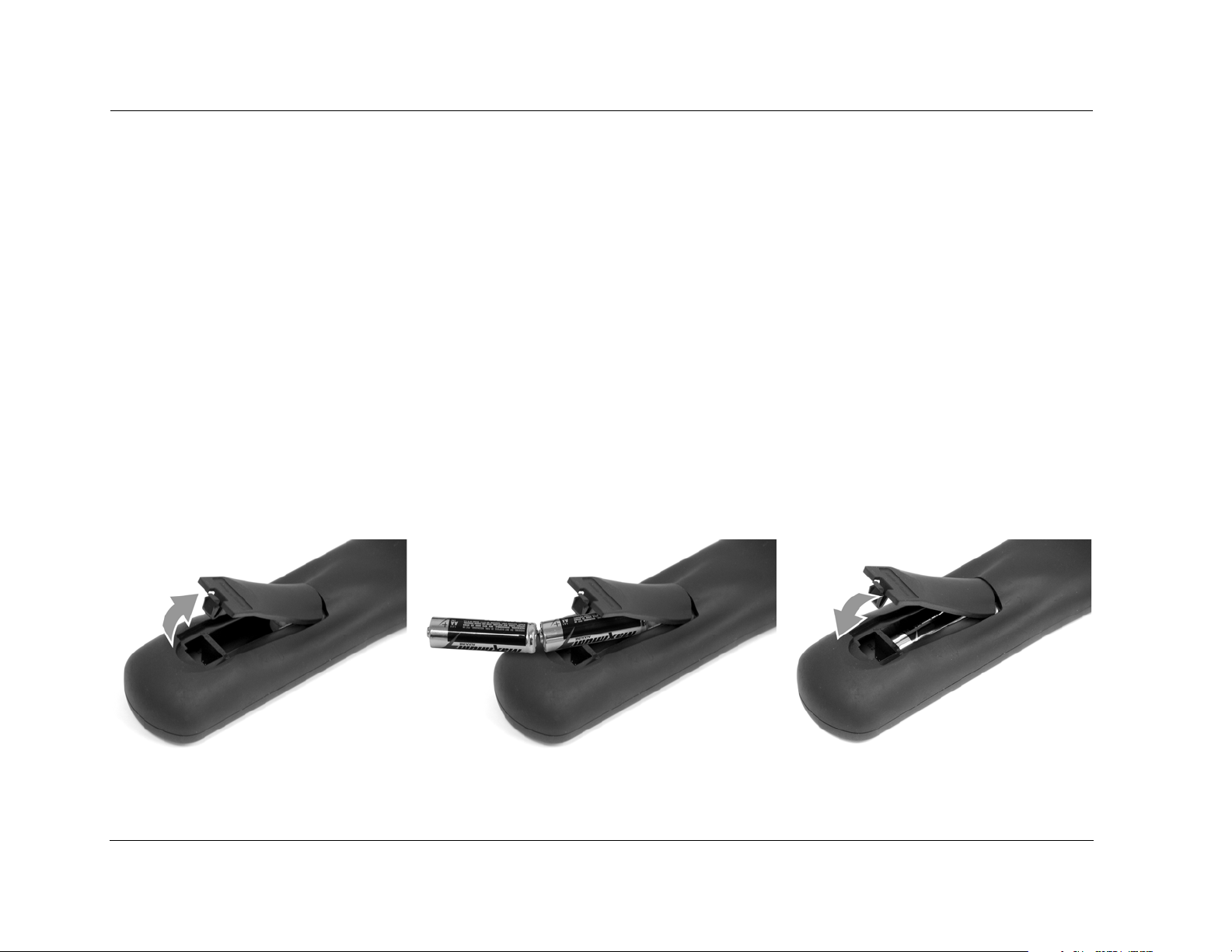
REMOTE CONTROL BATTERY INSTALLATION AND REPLACEMENT
The remote control requires two AA batteries (included).
To install the remote control batteries:
1. Locate the battery compartment on the back of the remote control. Press the tab and lift the cover away from the remote control.
2. Observing the proper polarity, insert two AA batteries.
3. Align the cover over the battery compartment and gently press down until it snaps back into place.
The batteries should be replaced as needed. Alkaline batteries, which last longer without leaking, are recommended. When battery power is
low, the remote control enters a low-voltage condition, preventing it from operating the SDP-40HD. When this occurs, replace the batteries.
Normal operation will resume when new batteries are installed.
To replace the remote control batteries, remove the old batteries and install new ones following steps above.
1-6
Page 13

2
Basic Operation
Front-Panel Overview ................................................................. 2-2
Rear-Panel Overview................................................................... 2-5
Remote Control Overview .......................................................... 2-9
Operation Considerations ......................................................................... 2-9
Command Bank Activation....................................................... 2-10
Command Matrix .................................................................................. 2-11
Menu Navigation ..................................................................... 2-16
Main Menu ............................................................................................ 2-16
Menu Item Selection .............................................................................. 2-17
About the Zones ...................................................................... 2-19
Two-line Status......................................................................... 2-19
Status Menus ........................................................................... 2-20
Status Menu Level Meters ...................................................................... 2-21
Status Menu Descriptions ....................................................................... 2-22
Status Menu Parameter Descriptions ....................................................... 2-26
Page 14
Basic Operation JBL
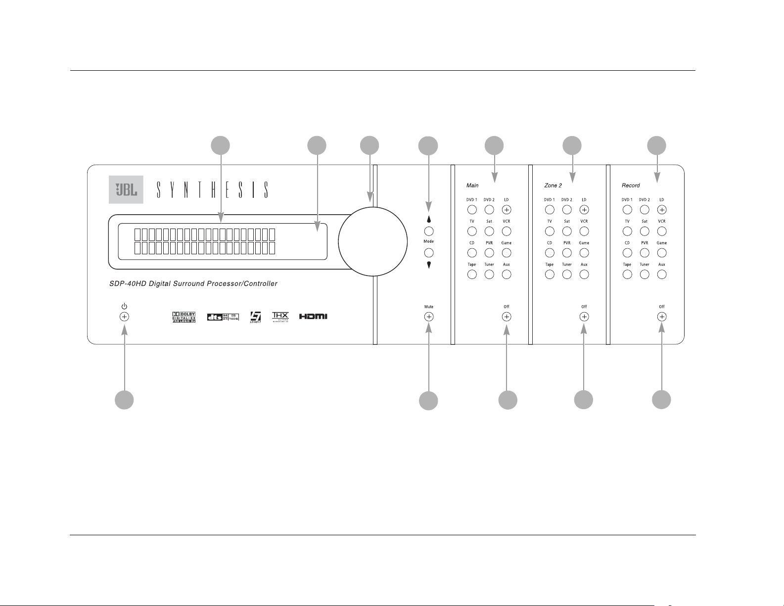
FRONT-PANEL OVERVIEW
The SDP-40HD is shown below. The numbers in the front panel illustration correspond with the numbered items below.
1
1
1. Standby Button
2. Front Panel Display
3. IR Receiver
2
3
4
5
12
7. Zone 2 Input Selection Buttons
8. Record Zone Input Selection Buttons
9. Record Zone Off Button
11
76
10
8
9
4. Volume Knob
5. Mode and Buttons
6. Main Zone Input Selection Buttons
2-2
10. Zone 2 Off Button
11. Main Zone Off Button
12. Mute Button
Page 15
SDP-40HD Basic Operation
1 STANDBY BUTTON
Use the Standby button to activate or deactivate standby mode.
The Standby button performs no function when the SDP-40HD rear
panel power switch is powered off. When standby mode is
deactivated, all SDP-40HD zones that were active during the last
session are reactivated. The red LED in the Standby button lights to
indicate that standby mode is activated. Power is still supplied to
the SDP-40HD when it is put into standby mode.
2 FRONT-PANEL DISPLAY
Use the front-panel display to view the current input, listening
mode, input source, and volume level. The 2 x 20 character display
also functions as a display for messages and menus.
3 IR RECEIVER
The IR receiver accepts infrared commands from the SDP-40HD
remote control. There are three associated LEDs.
• The amber LED blinks when a remote control command is
received.
• The red LED lights when the A/D converters are overloading.
• The blue LED lights when the SDP-40HD is powered on and
activated – even if the FRONT PANEL DISPLAY menu STATUS
parameter is set to ALWAYS OFF.
Amber LEDRed LED
Blue LED
4 VOLUME KNOB
Use the volume knob to adjust volume level in all zones.
Note:
When SDP-40HD output levels are properly calibrated, the +0dB volume
level setting corresponds to the THX reference level (75dB).
To adjust the Main Zone volume level:
Rotate the volume knob clockwise or
counterclockwise to increase or decrease the
volume level in 1dB increments. A horizontal
bar graph indicating the current Main Zone volume level appears in
the on-screen and front-panel displays. The Main Zone volume
range is –80 to +6dB.
To adjust the Zone 2 or Record Zone volume level:
1. Press and hold the front panel Zone 2 or Record Zone input selection button that corresponds with the current input source. For
example, if the current input source is DVD1, press and hold the
Zone 2 or Record Zone DVD1 input selection button.
2. Rotate the volume knob clockwise or
counterclockwise to increase or decrease
the volume level in 1dB increments. A horizontal bar graph appears on the onscreen and front panel displays. The Zone
2 or Record Zone volume ranges are –80
to +6dB.
3. When the Zone 2 or Record Zone volume level has been set,
release the input selection button.
Remote control input selection buttons cannot be used to select
Zone 2 or Record Zone volume level adjustment, even if the Zone 2
or Record Zone command bank is activated.
VOLUME -34dB
ZONE 2 VOLUME -34dB
RECORD VOLUME -34dB
2-3
Page 16

Basic Operation JBL
FRONT-PANEL OVERVIEW (continued)
5 MODE AND BUTTONS
Use the Mode buttons to scroll to the previous and next available
listening mode. Scrolling occurs in the order shown in the MODE
ADJUST menu (See “Mode Adjust” on page 2.). Press the
Mode button to scroll upward through available listening modes.
Press the Mode button to scroll downward through available
listening modes.
6 MAIN ZONE INPUT SELECTION BUTTONS
Selects an input in the Main Zone. When an input is selected, a
blue LED lights on the corresponding input selection button. When
the Main Zone is deactivated, pressing a Main Zone input selection
button activates the Main Zone and selects the corresponding
input. Zone 2 and the Record Zone remain deactivated until a Zone
2 or Record Zone input is selected.
7 ZONE 2 INPUT SELECTION BUTTONS
Selects the input in Zone 2. When an input is selected, an amber
LED lights on the corresponding input selection button. When
Zone 2 is deactivated, pressing a Zone 2 input selection button
activates Zone 2 and selects the corresponding input. The Main
and Record Zones remain deactivated until a Main or Record Zone
input is selected.
8 RECORD ZONE INPUT SELECTION BUTTONS
selection button activates the Record Zone and selects the
corresponding input. The Main Zone and Zone 2 remain
deactivated until a Main Zone or Zone 2 input is selected.
9 RECORD ZONE OFF BUTTON
Deactivates the Record Zone.
10 ZONE 2 OFF BUTTON
Deactivates Zone 2.
11 MAIN ZONE OFF BUTTON
Deactivates the Main Zone.
12 MUTE BUTTON
Press the Mute button to mute the SDP-40HD Main Zone volume;
"MUTE ON" appears in the on-screen and front panel displays.
Press the Mute button again to restore the SDP-40HD volume to its
original level. Under VOLUME CONTROL SETUP, the MUTE LEVEL
parameter can be used to set mute levels.
Mute can be activated automatically or manually. For example, the
SDP-40HD briefly activates mute when changing input sources or
listening modes. The amber LED on the Mute button lights
whenever mute is activated.
Selects an input in the Record Zone. When an input is selected, a
red LED lights on the corresponding input selection button. When
the Record Zone is deactivated, pressing a Record Zone input
2-4
Page 17
SDP-40HD Basic Operation
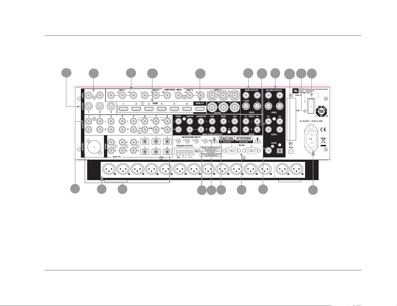
REAR-PANEL OVERVIEW
The SDP-40HD is shown below. The numbers in the rear-panel illustrations correspond with the numbered items.
1
20
1. S-video Input Connectors
2. Composite Video Input Connectors
3. Component Video Input Connectors
4. HDMI Input Connectors
5. HDMI Output Connector
6. Main Video Output Connectors
7. Zone 2 Audio Output Connectors
2
MAIN
AUDIO
OUTPUTS
19
3
18
4
CENTER SIDE REARFRONT ZONE 2AUXL RL RL RL R LFE L RLR
SUBWOOFER
8
7
14
6
13
5
17
15
16
8. Record Zone Video Output Connectors
9. IR In Connector
10. Removable Access Panel
11. Power Switch
12. AC Input Connector
13. Record Zone Audio Output Connectors
14. RS-232 Connectors
11
10
9
12
2-5
Page 18

Basic Operation JBL
15. Main Audio Output Connectors
16. Microphone Input Connectors
17. Trigger Output Connectors
18. Digital Audio Input Connectors (AES/EBU, S/PDIF, & OMJ)
19. Balanced Audio Output Connectors
20. Analog Audio Input Connectors
CAUTION!
Never make or break connections to the SDP-40HD unless
the SDP-40HD and all associated components are powered
off.
1 S-VIDEO INPUT CONNECTORS
Provides video input to the Main and Record Zones. Three S-video
connectors labeled S-VIDEO 1 to 3 are available.
2 COMPOSITE VIDEO INPUT CONNECTORS
Provides video input to the Main and Record Zones. Two
composite video connectors labeled VIDEO 1 and 2 are available.
4 HDMI INPUT CONNECTORS
Provides HDMI audio/video input to the Main Zone (not available for
the Record Zone). Six HDMI connectors labeled HDMI 1 to 6 are
available.
Note:
A DVI (Digital Visual Interface) device can be connected to the
SDP-40HD through a DVI-to-HDMI cable or adaptor. DVI carries video
but no audio.
5 HDMI OUTPUT CONNECTOR
Provides HDMI output from the Main Zone. One HDMI output
connector is available. The HDMI OUT connector supports HDCP
(High-bandwidth Digital Content Protection).
Note:
A DVI (Digital Visual Interface) device can be connected to the
SDP-40HD through a DVI-to-HDMI cable or adaptor. The DVI device
must be HDCP compliant.
6 MAIN VIDEO OUTPUT CONNECTORS
3 COMPONENT VIDEO INPUT CONNECTORS
Provides video input to the Main Zone. Four sets of component
video connectors (three RCA and one BNC) labeled INPUT 1 to 4
are available. The component video connectors are not available for
the Record Zone.
2-6
Provides video output from the Main Zone. Two composite video
connectors, two S-video connectors, and one set of component
video connectors (BNC) are available. The composite and S-video
connectors labeled 1 (OSD), and the component video connectors
incorporate the on-screen display.
Composite video output is available when a composite or S-video
source is present.
S-video output is available when an S-video source is present.
Page 19

SDP-40HD Basic Operation
Component video output is available when a component,
composite, or S-video source is present.
Note:
The video outputs that incorporate the on-screen display (OSD) can
also display the two-line status. However, to view the two-line status
through the component output, it must be configured to convert and
display composite or S-video. See “COMPONENT IN” on page
page 12.
CAUTION!
Never make or break connections to the SDP-40HD unless
the SDP-40HD and all associated components are powered
off.
7 ZONE 2 AUDIO OUTPUT CONNECTORS
Provides analog audio output from Zone 2. Two sets of stereo
connectors are available. The connectors labeled “Fix” pass audio
at fixed output levels. The connectors labeled “Var” pass audio at
variable output levels and include a built-in volume control.
8 RECORD ZONE VIDEO OUTPUT CONNECTORS
Provides video output from the Record Zone. Two composite video
connectors and two S-video connectors are available. These
connectors can be used to connect a monitor or video recording
device.
9 IR IN CONNECTOR
Accepts input of IR signals from infrared distribution equipment.
One 3.5mm jack that accepts a stereo plug (Tip/Ring/Sleeve
connection) or mono plug (Tip/Sleeve connection) is available.
10 REMOVABLE ACCESS PANEL
Covers the expansion slot, which is reserved for emerging
technologies.
11 POWER SWITCH
The Power Switch disconnects power from the AC Input Connector
(12) to the product. The I and O positions represent “on” and “off”
status, respectively. When the SDP-40HD is powered on, the frontpanel Standby button or remote control On button can be used to
activate and deactivate standby mode. When the SDP-40HD is
powered off, standby mode is not available.
12 AC INPUT CONNECTOR
Provides power to the SDP-40HD through the supplied power cord.
13 RECORD ZONE AUDIO OUTPUT CONNECTORS
Provides analog and digital audio output from the Record Zone.
Two stereo connectors labeled Audio L/R output analog audio. The
connector labeled “Fix” passes audio at a fixed output level. The
connector labeled “Var” passes audio at variable output levels and
includes a built-in volume control. Two S/PDIF connectors (one
coaxial and one optical) output digital audio.
These connectors can be used to connect a recording device. When
the Record Zone audio output connector labeled Var is connected
to a recording device, you should set the volume to +0dB to
achieve appropriate recording levels. See “REC PWR ON” on page
page 55 for more information.
2-7
Page 20

Basic Operation JBL
REAR-PANEL OVERVIEW (continued)
14 RS-232 CONNECTORS
The RS-232 serial connector (1) is used to perform backup and
restoration of configuration files and flash memory software
upgrades. The RS-232 connector (2) is capable of supporting
future developments.
15 MAIN ZONE AUDIO OUTPUT CONNECTORS
Provides analog audio output from the Main Zone. Ten connectors
labeled Front L/R, Center, LFE, Subwoofer L/R, Side L/R, and Rear L/
R are available. Two connectors labeled Aux L/R are provided for
future expansion.
16 MICROPHONE INPUT CONNECTORS
Provides microphone input. Four 3.5mm Tip/Ring/Sleeve
connectors are available.
18 DIGITAL AUDIO INPUT CONNECTORS
(AES/EBU & S/PDIF)
Provides digital audio input to all zones. One AES/EBU (XLR), six S/
PDIF coaxial (RCA), and six S/PDIF TOSLINK
connectors are available. These connectors are compatible with
PCM (44.1, 48, 88.2, and 96kHz), Dolby Digital, and DTS-ES
sources. These connectors are not compatible with MPEG or MP3
sources.
TM
optical input
19 BALANCED AUDIO OUTPUT CONNECTORS
Provides balanced analog audio outputs in the Main Zone and
Zone 2. Ten connectors labeled Front L/R, Center, LFE, Subwoofer
L/R, Side L/R, and Rear L/R are available in the Main Zone. The
connectors labeled Aux L/R are provided for future expansion. Two
connectors labeled Zone 2 L/R are available for Zone 2.
20 ANALOG AUDIO INPUT CONNECTORS
Provides analog audio input. Eight stereo analog audio input
connectors labeled 1 to 8 are available. Connectors labeled 6, 7
and 8 can be configured as 5.1-channel connectors.
17 TRIGGER OUTPUT CONNECTORS
Provides 12V DC output to control connected components. Three
trigger output connectors are available on a removable terminal
block. The PWR connector – the power trigger output connector –
cannot be configured. It is activated when the SDP-40HD is
activated, and deactivated when the SDP-40HD is deactivated. The
trigger output connectors (1) and (2) can be configured for remote
or program operation.
2-8
When a 5.1-channel analog audio source is present in the Main
Zone input signals are sent to the Main Zone audio output
connectors as indicated in the table on the following page. If the
ANALOG BYPASS is ON, a 5.1-channel analog source is present in
the Main Zone, and the INPUT SETUP menu ZONE2 IN or RECORD
IN parameter is set to DMIX, only the (L) and (R) input signals are
sent to the Zone 2 or Record Zone audio output connectors.
Page 21

SDP-40HD Basic Operation
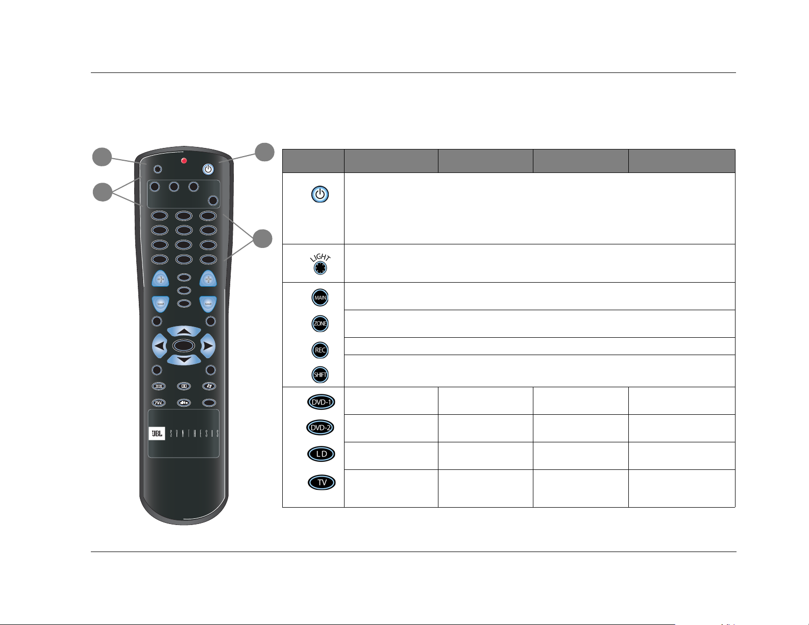
REMOTE CONTROL OVERVIEW
Input Connector Output Connector
(L) & (R) Front L/ R
(C) Center
(SUB) Subwoofer L/R & LFE
(LS) & (RS) Side L/R and Rear L/R
The SDP-40HD remote control provides full operation of the
SDP-40HD, including commands such as menu navigation that are
not available from the front-panel. The command matrix, beginning
on page 2-1100, indicates the commands that remote control
buttons perform when each command bank is active. The numbered
items in the matrix correspond with the remote control illustrations.
OPERATION CONSIDERATIONS
The following factors can improve or impede remote control
operation.
Note the following before operating the SDP-40HD remote control:
• The remote control must be in line of sight with the frontpanel IR receiver. Eliminate obstructions between the remote
control and the IR receiver. The remote control may become
unreliable if strong sunlight or fluorescent light shines on the IR
receiver.
• For optimal performance, position the remote control at a 30
degree angle no more than 17 feet (5m) from the SDP-40HD.
Placing the SDP-40HD inside a smoked glass cabinet will
reduce the remote control range.
• Remote controls for different components can interfere with
one another. Avoid using remote controls for different components at the same time.
• Remote control batteries should be replaced as needed.
2-9
Page 22

Basic Operation JBL
COMMAND BANK ACTIVATION
Remote control buttons perform different commands depending on
whether the Main Zone, Zone 2, Record Zone, or Shift command
bank is activated. Pressing and releasing a remote control command
bank selection button – MAIN, ZONE, REC, or SHIFT – activates the
corresponding command bank. The selected command bank
remains active until another command bank is activated.
The command bank selection buttons themselves do not send
commands to the SDP-40HD. When pressed and released, these
buttons activate the corresponding command bank. For example,
pressing and releasing the SHIFT button activates the Shift
command bank. When the Shift command bank is activated,
pressing and releasing the DVD-1 button turns off the Main Zone.
See Command Matrix, page 2-11.
To activate a command bank:
1. Press and release a command bank selection button to activate
the desired command bank.
The command matrix that begins on the next page indicates
which commands the remote control buttons perform when
each command bank is activated.
The MAIN MENUSETUPDISPLAYSON-SCREEN DISPLAY
menu REMOTE STATE parameter controls the remote control
command bank indicator that appears on the on-screen display.
When the REMOTE STATE parameter is set to ON, a command
bank indicator appears in the top-right corner of the on-screen
display to indicate the last command bank from which the
SDP-40HD received a command. A “Z” appears to indicate Zone 2.
An “R” appears to indicate the Record Zone. An “S” appears to
indicate the Shift command bank. No letter appears when the Main
Zone command bank is active. When the REMOTE STATE
parameter is set to OFF, no command bank indicator appears on
the on-screen display.
Note:
Remote control command bank selection buttons should not be pressed
and held.
2. Press a remote control button to send a command to the
SDP-40HD.
2-10
Page 23
SDP-40HD Basic Operation
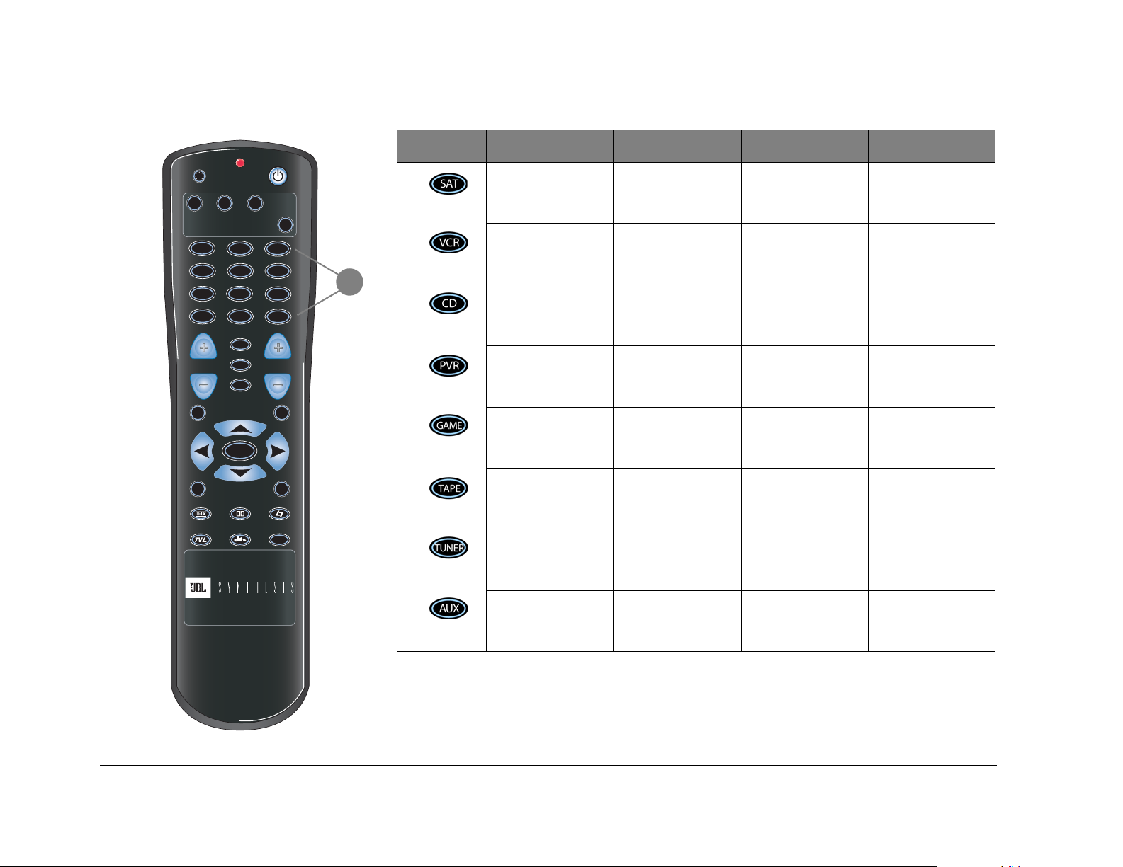
COMMAND MATRIX
The numbers in the remote control illustrations correspond to the
numbered items in the matrix. The sections following the
2
3
H
G
T
I
L
MAIN
ZONE REC
DVD-1
DVD-2 L D
TV
SAT
CD
PVR
TAPE TUNER
FP
MODE VOL
STAT
BLUE
OSD
MENU
7 / 5 2 CH
SHIFT
VCR
GAME
AUX
MUTE
1
Button Main Zone Zone 2 Record Zone Shift
1
4
2
3
Activates and deactivates standby mode when the SDP-40HD rear panel power switch is in the on position.
When standby mode is activated, pressing the standby button deactivates standby mode and activates the
SDP-40HD, including all zones that were activated during the previous operating session. When standby
mode is deactivated, pressing the standby button activates standby mode and deactivates the SDP-40HD. The
red front panel standby button LED lights to indicate that standby mode is activated.
Note: Power is still supplied to the SDP-40HD when standby mode is activated.
Activates the remote control back-light, illuminating remote control buttons to make them more visible in the
dark. The back-light also illuminates whenever a remote control button is pressed. Once illuminated, the backlight remains on for about 5 seconds before extinguishing.
Activates the Main Zone command bank, which includes commands that control the Main Zone.
Activates the Zone 2 command bank, which includes commands that control Zone 2 and the Main Zone.
Activates the Record Zone command bank, which includes commands that control the Record Zone.
Activates the Shift command bank, which includes commands that control all zones.
command matrix provide a more detailed explanation of the
functionality and menu structure of the digital controller that can
be accessed through the remote control.
MUSIC
4
Selects the DVD1 input
for the Main Zone.
Selects the DVD2 input
for the Main Zone.
Selects the LD input for
the Main Zone.
Selects the TV input for
the Main Zone.
Selects the DVD1 input
for Zone 2.
Selects the DVD2 input
for Zone 2.
Selects the LD input for
Zone 2.
Selects the TV input for
Zone 2.
Selects the DVD1 input
for the Record Zone.
Selects the DVD2 input
for the Record Zone.
Selects the LD input for
the Record Zone.
Selects the TV input for
the Record Zone.
Deactivates the Main Zone.
Deactivates Zone 2.
Deactivates the Record
Zone.
Sets the AUDIO CONTROLS
menu LOUDNESS parameter
to ON.
2-11
Page 24
Basic Operation JBL
Button Main Zone Zone 2 Record Zone Shift
H
G
T
I
L
MAIN
ZONE REC
DVD-1
DVD-2 L D
TV
SAT
CD
PVR
GAME
TAPE TUNER
FP
MODE VOL
STAT
7 / 5 2 CH
BLUE
OSD
MENU
4
SHIFT
VCR
4
AUX
MUTE
MUSIC
Selects the SAT input for
the Main Zone.
Selects the VCR input for
the Main Zone.
Selects the CD input for
the Main Zone.
Selects the PVR input for
the Main Zone.
Selects the GAME input
for the Main Zone.
Selects the TAPE input
for the Main Zone.
Selects the TUNER input
for the Main Zone.
Selects the AUX input
for the Main Zone.
Selects the SAT input for
Zone 2.
Selects the VCR input for
Zone 2.
Selects the CD input for
for Zone 2.
Selects the PVR input for
Zone 2.
Selects the GAME input
for Zone 2.
Selects the TAPE input
for Zone2.
Selects the TUNER input
for Zone 2.
Selects the AUX input
for Zone 2.
Selects the SAT input for
the Record Zone.
Selects the VCR input
for the Record Zone.
Selects the CD input for
the Record Zone.
Selects the PVR input for
the Record Zone.
Selects the GAME input
for the Record Zone.
Selects the TAPE input
for the Record Zone.
Selects the TUNER input
for the Record Zone.
Selects the AUX input
for the Record Zone.
Sets the AUDIO CONTROLS menu LOUDNESS parameter to OFF.
Reserved for possible
future expansion.
Increases the AUDIO
CONTROLS menu BASS
parameter in 0.5dB
increments.
Increases the AUDIO
CONTROLS menu TREBLE parameter in 0.5dB
increments.
Increases the AUDIO
CONTROLS menu TILT
EQ parameter in 0.2dB
increments.
Decreases the AUDIO
CONTROLS menu BASS
parameter in 0.5dB
increments.
Decreases the AUDIO
CONTROLS menu TREBLE parameter in 0.5dB
increments.
Decreases the AUDIO
CONTROLS menu TILT
EQ parameter in 0.2dB
increments.
2-12
Page 25
SDP-40HD Basic Operation
H
G
T
I
L
Button Main Zone Zone 2 Record Zone Shift
MAIN
ZONE REC
SHIFT
DVD-1
DVD-2 L D
TV
SAT
VCR
CD
PVR
GAME
5
TAPE TUNER
8
MODE VOL
STAT
AUX
6
FP
BLUE
OSD
MUTE
9
7
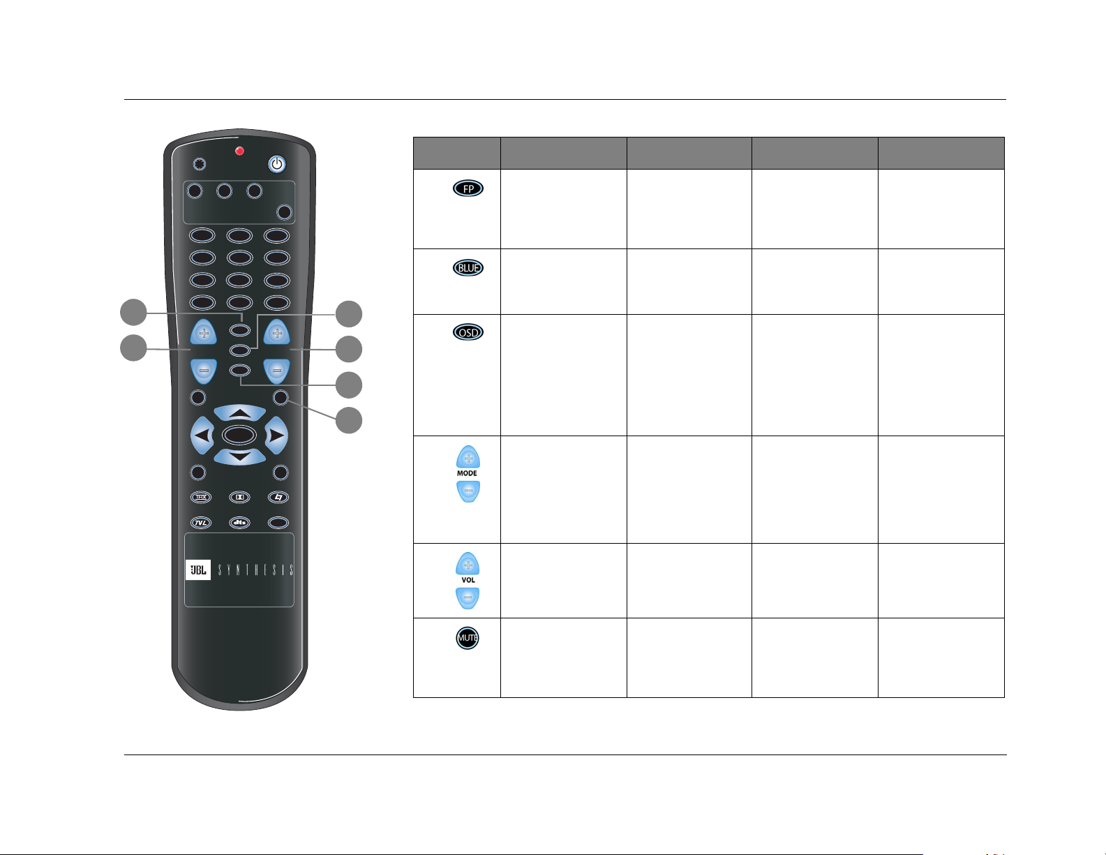
5
6
7
Toggles the FRONT
PANEL DISPLAY menu
STATUS parameter
between ALWAYS OFF
and the current setting.
Toggles the ON SCREEN
DISPLAY menu BACKGROUND parameter
between ON and OFF.
Toggles the ON SCREEN
DISPLAY menu STATUS
parameter between
ALWAYS OFF and the
current setting.
Sets Zone 2 volume
level to -15dB
Sets Zone 2 volume
level to -30dB
Reserved for possible
future expansion.
Sets Record Zone volume level to -15dB
Sets Record Zone volume level to -30dB
Reserved for possible
future expansion.
Sets Main Zone volume
level to -15dB.
Sets Main Zone volume
level to -30dB.
Sets the AUDIO CONTROL menu BASS, TREBLE, and TILT EQ
parameters to +0.0dB.
However, the screen displays:
EQ BALANCE
MENU
7 / 5 2 CH
MUSIC
10
8
9
Scroll to the previous or
next available listening
mode, with the current
Main Zone input source.
Scrolling occurs in the
order shown on the
MODE ADJUST menu.
Increases and decreases
Main Zone volume level
in 1dB increments.
Activates (+) and deactivates (-) the trigger output connector labeled 1
when the connector is
configured for remote
operation.
Increases and decreases
Zone 2 volume level in
1dB increments.
Activates (+) and deactivates (-) the trigger output connector labeled 2
when the connector is
configured for remote
operation.
Increases and decreases
Record Zone volume
level in 1dB increments.
EQ OFF
Deactivates (+) and activates (-) standby mode
when the SDP-40HD is
powered on with the rear
panel power switch.
Increases and decreases
Main Zone volume level
in 3dB increments.
10
Toggles between lowering Main Zone volume
level and restoring Main
Zone volume to the
original level.
Toggles between full
Zone 2 muting and
restoring Zone 2 volume to the original
level.
Toggles between full
Record Zone muting
and restoring Record
Zone volume to the
original level.
Toggles between full
Main Zone muting and
restoring Main Zone volume to the original level.
2-13
Page 26
Basic Operation JBL
H
G
T
I
L
Button Main Zone Zone 2 Record Zone Shift
11
12
13
14
MAIN
ZONE REC
DVD-1
DVD-2 L D
TV
SAT
CD
PVR
GAME
TAPE TUNER
FP
MODE VOL
STAT
7 / 5 2 CH
BLUE
OSD
MENU
VCR
AUX
MUSIC
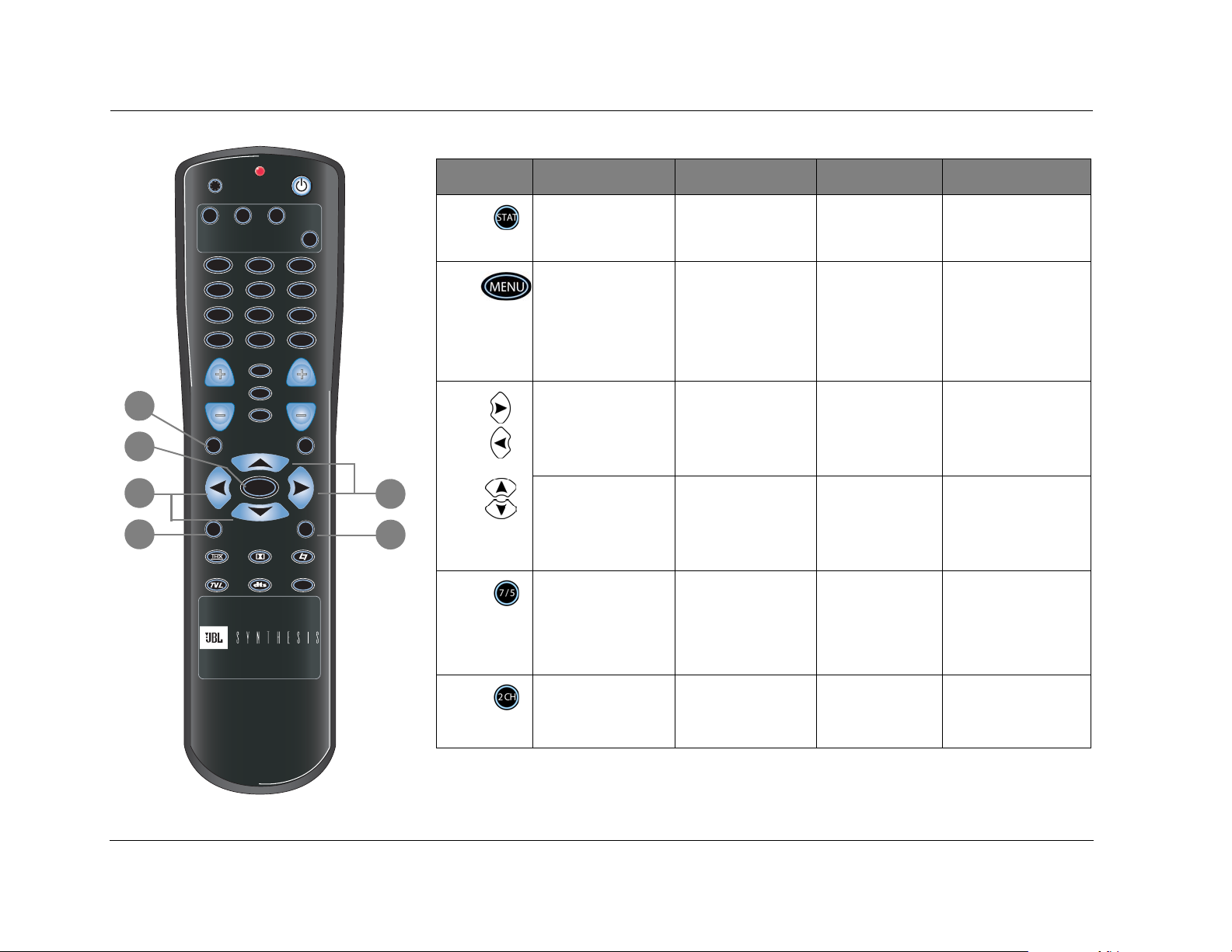
11
SHIFT
12
Displays the Main Zone
two
-line status for 2 sec-
onds.
When a menu is open,
pressing the MENU button closes the structure.
When no menus are
Displays the Zone 2
two-line status for 2 seconds.
Centers the AUDIO
CONTROLS menu
ZONE2 BALANCE
parameter.
Displays the Record
Zone two-line status
for 2 seconds.
Centers the AUDIO
CONTROLS menu
RECORD BALANCE
parameter.
Opens and closes the status menu for the current
input source.
Centers the AUDIO CONTROLS menu Main Zone
BALANCE and FADER
parameters.
open, pressing the
MENU button opens the
MAIN MENU.
13
Closes the current ()
menu or opens the
menu structure and
MUTE
13
selects the highlighted
menu item (
).
Scroll upward and
downward through
menu items.
15
14
Toggles between 7channel and 5-channel
Adjusts the AUDIO
CONTROLS menu
ZONE2 BALANCE
parameter left and right.
Increase and decrease
subwoofer output levels
applied to the current
listening mode.
Reserved for possible
future expansion.
Adjusts the AUDIO
CONTROLS menu
RECORD BALANCE
parameter left and
right.
Reserved for possible
future expansion.
Reserved for possible
future expansion.
playback.
Adjusts the AUDIO CON-
TROLS menu Main Zone
BALANCE parameters left
and right.
Adjusts the AUDIO CON-
TROLS menu Main Zone
FADER parameters for-
ward (
) and backward
).
(
Adjusts the MAIN ADV
menu INPUT SELECT
parameter, cycling
through the ANALOG,
DIGITAL, and AUTO set-
tings.
15
Toggles between the
current listening mode
and the 2-CHANNEL listening mode.
Reserved for possible
future expansion.
Reserved for possible
future expansion.
Toggles the MAIN ADV
menu ANALOG BYPASS
parameter between ON
and OFF.
2-14
Page 27
SDP-40HD Basic Operation
16
H
G
T
I
L
MAIN
ZONE REC
DVD-1
DVD-2 L D
TV
SAT
VCR
CD
PVR
GAME
TAPE TUNER
MODE VOL
STAT
MENU
7 / 5 2 CH
AUX
FP
BLUE
OSD
MUSIC
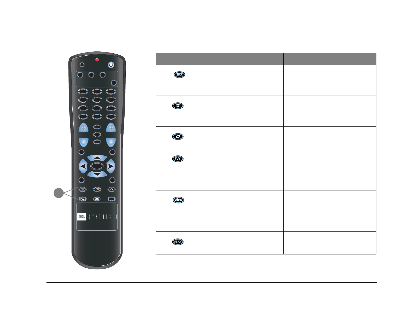
Button Main Zone Zone 2 Record Zone Shift
Selects the THX mode
16
SHIFT
family for the current
input source.
Selects the Dolby mode
family for the current
Reserved for possible
future expansion.
Reserved for possible
future expansion.
input source.
Selects the LOGIC 7 FILM
mode family for the cur-
Reserved for possible
future expansion.
rent input source.
MUTE
Selects the LOGIC 7 TV
mode family for the cur-
Reserved for possible
future expansion.
rent input source.
Selects the DTS mode
family for the current
Reserved for possible
future expansion.
input source.
Selects the LOGIC 7
MUSIC mode family for
Reserved for possible
future expansion.
the current input source.
Reserved for possible
future expansion.
Reserved for possible
future expansion.
Reserved for possible
future expansion.
Reserved for possible
future expansion.
Reserved for possible
future expansion.
Reserved for possible
future expansion.
Activates the THX UL2Cin
or the THX SurEX listening mode when a
5.1
-channel Dolby Digital
source is present.
Activates the Dolby Digital EX or Dolby Digital
listening mode when a
5.1
-channel Dolby Digi-
tal source is present.
Activates the PANORAMA listening mode.
Activates the MONO
LOGIC listening mode
for 2
-channel sources
and the 5.1 MONO
LOGIC listening mode
for 5.1 channel Dolby
Digital sources.
When a DTS
(-ES) source
is present, pressing the
dts button toggles the
ES DECODING parameter, cycling through the
AUTO, ON, and OFF settings.
Activates the L7 MUSIC
SURR listening mode.
2-15
Page 28
Basic Operation JBL
MENU NAVIGATION
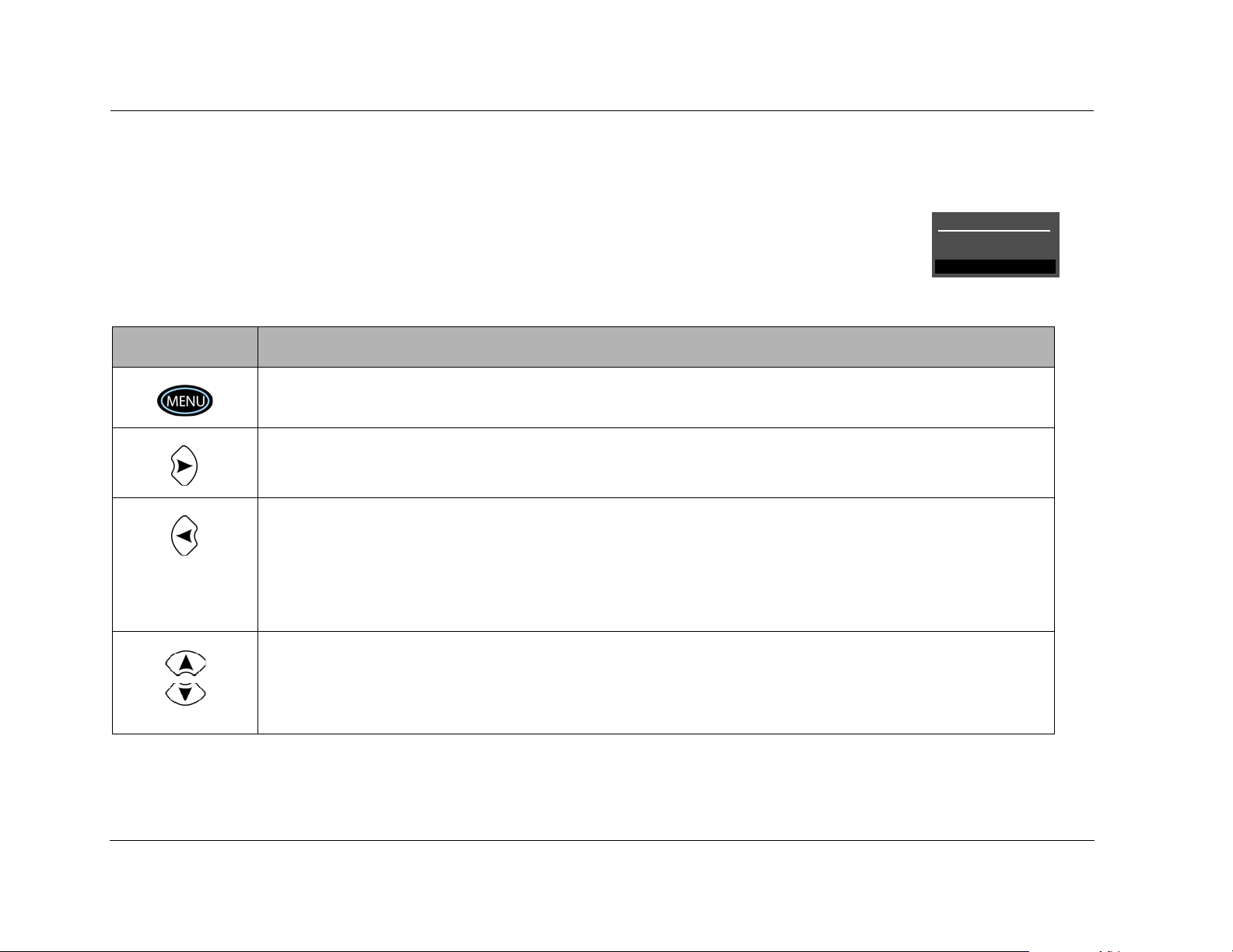
Use the remote control Menu and arrow buttons to navigate the
extensive menu structure shown in the Appendix. The table below
indicates the navigation commands that the remote control
buttons perform when the Main Zone command bank is activated.
Button Navigation Function(s)
• When no menus are displayed, press the MENU button to open the MAIN MENU.
• When a menu is open, press the MENU button to close the menu structure.
• When no menus are displayed, press the arrow button to open the MAIN MENU.
• When a menu is open, press the arrow button to select the highlighted menu item.
• When a menu is open, press the arrow button to close the menu and, in most cases, open the previous
menu. Subsequent presses continue to close the current menu and open the previous menu until the MAIN
MENU is closed. When the MAIN MENU is closed, the menu structure is also closed.
• When no menus are displayed, pressing the arrow button performs no function.
• When a drop-down menu is open, press the arrow button to select the current setting and close the dropdown menu.
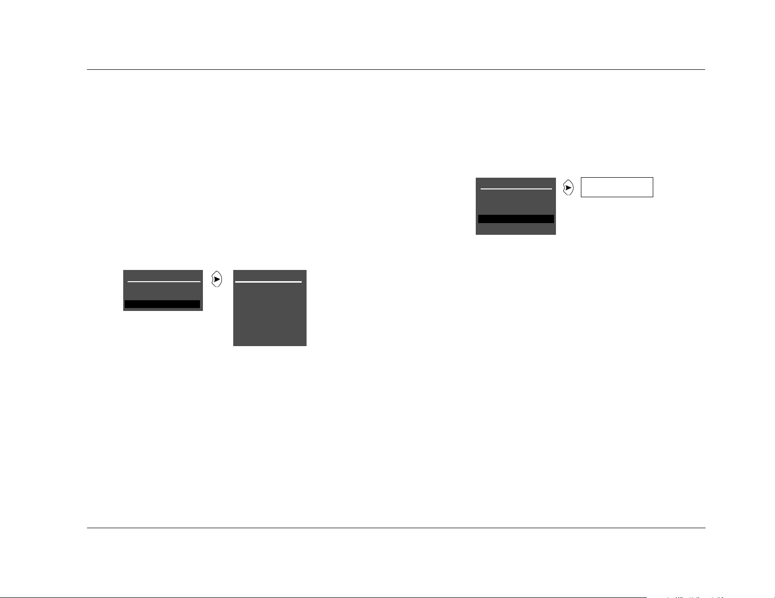
MAIN MENU
The MAIN MENU represents the
beginning of the menu structure. Use
the MAIN MENU to open the three main
menu branches: MODE ADJUST, AUDIO
CONTROLS, and SETUP.
MAIN MENU
MODE ADJUST
AUDIO CONTROLS
SETUP
2-16
• When a menu is open, press the or arrow buttons to scroll upward or downward through the complete
list of menu items. All menu items are displayed on-screen. A scroll bar appears on the left side of the menu
when menu items exceed the top and bottom margins of the display, and the cursor automatically advances
to the next menu item when the first or last menu item is passed. The highlighted menu item is displayed on
the SDP-40HD front panel.
MENU ITEM SELECTION
Use the remote control Menu arrows to select menu items.
Page 29
SDP-40HD Basic Operation
To select a menu item:
1. Press the remote control or arrow buttons to highlight the
desired menu item.
2. When the desired menu item is highlighted, press the arrow
button to select the highlighted item. If you select an option,
another menu displays. If you select a parameter, a parameter
menu or horizontal graph opens.
MENU OPTIONS
Selecting a menu option opens another menu within the menu
structure. For example, selecting SETUP from the MAIN MENU opens
the SETUP menu.
MAIN MENU
MODE ADJUST
AUDIO CONTROLS
SETUP
SETUP
SETUP
INPUTS
SPEAKERS
REAR PANEL CONFIG
DISPLAYS
VOLUME CONTROLS
TRIGGER
LOCK OPTIONS
PARAMETER DROP-DOWN MENUS
When certain menu parameters are selected, a drop-down menu
opens with a list of available parameter settings. For example,
selecting the DISPLAY SETUP menu CUSTOM NAME parameter
opens a drop-down menu for selecting the ON or OFF setting.
DISPLAY SETUP
ON-SCREEN DISPLAY
FRONT PANEL DISPLAY
A/V SYNC DELAY OFF
CUSTOM NAME OFF
EDIT CUSTOM NAME
To select a setting in a parameter drop-down menu:
1. When the drop-down menu opens, press the remote control
or arrow button to scroll up or down through the complete list of available settings. The current setting is displayed
beneath the parameter name in the on-screen and front-panel
displays.
2. When the desired setting appears beneath the parameter
name, press the arrow button to accept the setting and
close the drop-down menu.
ON
OFF
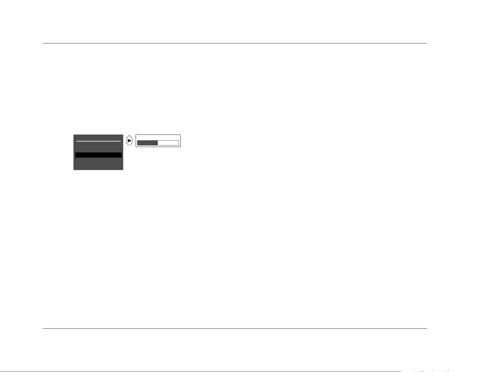
MENU PARAMETERS
Selecting a menu parameter opens a drop-down menu or
horizontal bar graph that is used to select the desired setting.
2-17
Page 30
Basic Operation JBL
HORIZONTAL BAR GRAPHS
Selecting some menu parameters opens a horizontal bar graph. The
bar graph indicates the position of the current parameter setting
within the entire parameter range. The setting appears to the right of
the parameter name in the on-screen and front-panel displays.
For example, selecting the DISPLAY SETUP menu A/V SYNC DELAY
parameter opens the horizontal bar graph shown below, which is
used to adjust the amount of audio delay.
DISPLAY SETUP
ON-SCREEN DISPLAY
FRONT PANEL DISPLAY
A/V SYNC DELAY OFF
CUSTOM NAME OFF
EDIT CUSTOM NAME
OFF, 1 to 60ms
To adjust a parameter setting with a horizontal bar graph:
1. When the horizontal bar graph appears, press the remote control or arrow button to increase or decrease the setting in
designated increments.
The setting appears to the right of the parameter name in the
on-screen and front-panel displays.
2. When you have finished adjusting the settings, press the arrow
button to select the current setting and close the horizontal bar
graph.
2-18
Page 31

SDP-40HD Basic Operation
ABOUT THE ZONES
The SDP-40HD features three zones of operation: the Main Zone,
Zone 2, and the Record Zone. The Main Zone controls audio and
video sources in the primary listening space. Zone 2 controls
audio sources in the secondary listening space. The Record Zone
controls audio and video sources sent to recording devices or to a
third listening space.
These zones have separate digital audio receivers and dedicated
analog source selectors that allow for independent input
selection in each zone. The SDP-40HD can process input sources
in three zones at the same time. For example, the SDP-40HD can
play a DVD in the Main Zone, while playing a CD in Zone 2,
while sending satellite receiver signals to a VCR in the Record
Zone.
The following are exceptions to independent zone operation:
1. When a Dolby Digital or DTS(-ES) source is present in the
Main Zone, the same Dolby Digital or DTS(-ES) source can
also be present in Zone 2 or the Record Zone. However, a different Dolby Digital or DTS(-ES) source cannot be present in
Zone 2 or the Record Zone.
2. Main Zone multi-channel audio can be down-mixed in Zone 2
or the Record Zone when all of the following conditions are
met:
• The MAIN MENUSETUPINPUTSINPUT SETUP
menu ZONE2 IN or RECORD IN parameter is set to
DMIX.
3. When the MAIN MENUSETUPINPUTSINPUT SETUP
menu ZONE2 IN or RECORD IN parameter is set to ANLG, the
Zone 2 or Record Zone audio output connectors are not available during 5.1mc BYPASS listening mode. However, it is possible to have a 5.1-channel analog audio source present in the
Main Zone and a digital audio source present in Zone 2 or the
Record Zone.
4. When an HDMI source is selected for digital audio input, the
down-mixed audio is available on the digital audio output in
the Record Zone. When the source on the HDMI connector is
copy-protected DVD-Audio, no digital audio is output, but
analog audio is still output.
• A Dolby Digital or DTS(-ES) source is present in the Main
Zone.
• The Main Zone input is also selected in Zone 2 or the
Record Zone. For example, if the DVD1 input is selected
in the Main Zone, the DVD1 input must also be selected
in Zone 2 or the Record Zone.
2-19
Page 32

Basic Operation JBL
TWO-LINE STATUS
The two-line status opens on the on-screen and front panel displays
whenever the SDP-40HD detects a status change such as a new
input source or listening mode. The information included on the
two-line status differs depending on the zone in which the
SDP-40HD last detected a status change.
MAIN ZONE TWO-LINE STATUS
Opens on the on-screen and front panel
displays whenever the Main Zone status
changes. The Main Zone two-line status
indicates the current input, listening mode, input source, and
volume level selected in the Main Zone.
ZONE 2 TWO-LINE STATUS
Opens on the on-screen and front panel
displays whenever the Zone 2 status changes.
The Zone 2 two-line status indicates the
current input, input source, and volume level selected in Zone 2.
DVD1 D VOL
FILM
DVD 1 D VOL
ZONE 2
-34dB
-34dB
vertical alignment of the two-line status on the display device
screen.
Notes:
• When the display device is connected to a component video output
connector and the ADVANCED menu COMPONENT OSD parameter is
set to OFF, the display device does not show the on-screen display,
including the two-line status.
• The two-line status displays on the component video output only when
VIDEO IN is set to composite or S-video and COMPONENT IN is set to
VIDEO.
RECORD ZONE TWO-LINE STATUS
Opens on the on-screen and front panel
displays whenever the Record Zone status
changes. The Record Zone two-line status
indicates the current input, input source, and volume level selected
in the Record Zone.
The ON-SCREEN DISPLAY menu STATUS parameter controls how
long the two-line status appears on the on-screen display. The
ON-SCREEN DISPLAY menu POSITION parameter controls the
2-20
DVD 1 D VOL
RECORD
-34dB
Page 33

SDP-40HD Basic Operation
STATUS MENUS
The STATUS menu contains parameters that provide information about
the current input source and listening mode. Status menus are available
for HDMI, 2-channel, Dolby Digital, DTS(-ES), analog, and digital input
sources.
All status menus include the letter “S” at the top right corner.
Certain status menus also include level meters that indicate
fluctuating audio input levels. Some status menus have more
information than can fit on one screen, or page. These status
menus have two or three pages, and are identified by the caret (>)
near the top right corner.
D STATUS
INPUT
MODE
CHANNELS
BIT RATE
EX ENCODED
RL
CSLSRLFE
dB
0
-6
-15
-30
-45
>
S
D STATUS
SAMPLE RATE
2.0 ENCODING
DIALOG OFFSET
MIX ROOM
CENTER MIX LVL
SURR MIX LVL
S
If HDMI audio or video is active, the HDMI status menu will appear
before other status menus.
HDMI STATUS > S
HDMI CONNECTOR
VID FMT
VERT RATE
AUD IN
AUDIO FMT
CHANNELS
SAMPLE RATE
HDCP STATUS
D STATUS
INPUT
MODE
CHANNELS
BIT RATE
EX ENCODED
RL
CSLSRLFE
dB
0
-6
-15
-30
-45
>S
D STATUS
SAMPLE RATE
2.0 ENCODING
DIALOG OFFSET
MIX ROOM
CENTER MIX LVL
SURR MIX LVL
S
Unlike most other menus, status menus cannot be opened by
selecting menu options. The remote control command sequence
outlined below must be executed.
To open and navigate the STATUS menu for the current input
source:
1. Press and release the remote control SHIFT button.
2. Press and release the remote control STAT button.
The first page of the STATUS menu for the current input source
appears in the on-screen and front-panel displays.
3. If the > indicator appears near the top right corner of the
menu, press and release the STAT button again to open the
second page. Press and release the STAT button again to open
the third page (if one exists).
If the STATUS menu does not include a second or third page, press-
ing and releasing the STAT button again closes the menu.
Note:
When viewing a STATUS menu on the front panel display, press the
remote control MAIN button, then press the or arrow button to
scroll up or down through the list of available parameters.
2-21
Page 34

Basic Operation JBL
4. Press the STAT button to close the STATUS menu. In some
cases, you must press STAT twice in succession to close the
STATUS menu.
Note:
STATUS menu parameters provide information about the current
input source and listening mode. These parameters cannot be
adjusted.
STATUS MENU LEVEL METERS
Most STATUS menus contain level meters that indicate fluctuating
input levels in the front left (L), center (C), front right (R), surround left
(SL), surround right (SR), surround back (SB) and low frequency effects
(LFE) channels. These level meters indicate input levels for both analog
and digital input sources. For example, the level meters indicate digital
audio input levels when a digital audio source is present.
Different combinations of level meters appear on each STATUS
menu, depending on the current source. The SB level meter appears
when a 6.1-channel source or a 5.1-channel source is present and
the ES DECODING parameter is set to ON.
Level meters appear in combinations of green, yellow and red
when the on-screen display is configured for a blue screen
background. Green indicates low levels, yellow indicates normal
levels, and red indicates high levels and the onset of overload. Level
meters appear in white when the on-screen display is not
configured for a blue screen background.
STATUS MENU DESCRIPTIONS
The table beneath each description lists the possible settings for
each parameter.
HDMI STATUS
Provides information about HDMI input sources. VID FMT is the
video format. VERT RATE is the vertical scan rate frequency.
Parameter Possible Settings
HDMI CONNECTOR 1–6
VID FMT (video format) 480i, 480p, 720p, 1080i, ---
VERT RATE (vertical scan rate) 60Hz, 50Hz, 59.94Hz, ---
AUD IN HDMI, OPTICAL1–6, COAX1–6,
ANALOG, 5.1 ANLG (6–8)
AUDIO FMT DD, DTS, PCM, N/A
CHANNELS 6.1, 5.1, 5.0, 2.1, 2.0, 1.0, N/A
SAMPLE RATE 44.1kHz, 48kHz, 88.2kHz, 96kHz, N/A
HDCP STATUS ACTIVE, INACTIVE, ERROR
See “Status Menu Parameter Descriptions” on page 27 for detailed information.
HDMI STATUS > S
HDMI CONNECTOR
VID FMT
VERT RATE
AUD IN
AUDIO FMT
CHANNELS
SAMPLE RATE
HDCP STATUS
2-22
Page 35

SDP-40HD Basic Operation
2CH STATUS
Provides information about 2-channel input sources. Features L and
R level meters.
Parameter Possible Settings
INPUT Current input
MODE Current listening mode
INPUT TYPE ANLG, PCM
SAMPLE RATE 44.1kHz, 48kHz, 88.2kHz, 96kHz
See “Status Menu Parameter Descriptions” on page 27 for detailed information.
2CH STATUS
INPUT
MODE
INPUT TYPE
SAMPLE RATE
RL
dB
0
-6
-15
-30
-45
S
D STATUS
Provides information about Dolby Digital input sources. Features L,
C, R, SL, SR, SB, and LFE level meters.
Parameter Possible Settings
INPUT Current input
MODE Current listening mode
CHANNELS 3/2.1, 3/2, 3/1, 2/2, 2/1, 2/0, 1/0
BIT RATE 32 to 640kbps
EX ENCODED YES, NO
SAMPLE RATE 48kHz
2.0 ENCODING MATRIX, NONE
DIALOG OFFSET -27 to +4dB
MIX ROOM SMALL, LARGE
CENTER MIX LVL -3.0dB, -4.5dB, -6.0dB
SURR MIX LVL +0.0dB, -3.0dB, -6.0dB
See “Status Menu Parameter Descriptions” on page 27 for detailed information.
D STATUS
INPUT
MODE
CHANNELS
BIT RATE
EX ENCODED
RL
CSLSRLFE
dB
0
-6
-15
-30
-45
>S
D STATUS
SAMPLE RATE
2.0 ENCODING
DIALOG OFFSET
MIX ROOM
CENTER MIX LVL
SURR MIX LVL
S
2-23
Page 36

Basic Operation JBL
STATUS
Provides information about DTS(-ES) input sources. Includes L, C, R,
SL, SR, SB and LFE level meters.
Parameter Possible Settings
INPUT Current input
MODE Current listening mode
CHANNELS 3/3.1, 3/2.1
BIT RATE 754.5 to 1509.7kbps
ES ENCODING DISCRETE, MATRIX, OFF
WORD LENGTH 16 bits, 20 bits, 24 bits
SAMPLE RATE 44.1kHz, 48kHz, 88.2kHz, 96kHz
See “Status Menu Parameter Descriptions” on page 27 for detailed information.
STATUS
INPUT
MODE
CHANNELS
BIT RATE
ENCODING
dB
RL
CSLSRLFE
0
-6
-15
-30
-45
>S S
SB
STATUS
STATUS
WORD LENGTH
WORD LENGTH
SAMPLE RATE
SAMPLE RATE
5.1mc STATUS
Provides information about 5.1-channel sources. Includes L, C, R,
SL, SR, and LFE level meters.
Parameter Possible Settings
INPUT Current input
MODE Current listening mode
INPUT TYPE ANLG, PCM
SAMPLE RATE 44.1kHz, 48kHz, 96kHz
Note:
The only possible sample rate for 5.1 analog sources is 96kHz, as they
are converted to 96kHz PCM at the SDP-40HD input (when MAIN
ADVANCED ANALOG BYPASS is set to OFF).
See “Status Menu Parameter Descriptions” on page 27 for detailed information.
5.1mc STATUS
INPUT
MODE
INPUT TYPE
SAMPLE RATE
dB
RL CSLSRLFE
0
-6
-15
-30
-45
S
STATUS
WORD LENGTH
SAMPLE RATE
PG1
2-24
Page 37

SDP-40HD Basic Operation
5.1a BYPASS STATUS
Provides information about 5.1-channel analog input sources when
the MAIN ADV menu ANALOG BYPASS parameter is set to ON.
Parameter Possible Settings
INPUT Current input
MODE 5.1a BYPASS
INPUT TYPE BYPASS
See “Status Menu Parameter Descriptions” on page 27 for detailed information.
5.1a BYPASS STATUS
INPUT
MODE
INPUT TYPE
S
2CH BYPASS STATUS
Provides information about 2-channel analog input sources when
the MAIN ADV menu ANALOG BYPASS parameter is set to ON.
Parameter Possible Settings
INPUT Current input
MODE 2CH BYPASS
INPUT TYPE BYPASS
See “Status Menu Parameter Descriptions” on page 27 for detailed information.
2CH BYPASS STATUS
INPUT
MODE
INPUT TYPE
S
2-25
Page 38

Basic Operation JBL
DIGITAL STATUS
Provides information about digital input sources for which a sample
rate is detected, but no audio is present in the input signal.
Parameter Possible Settings
INPUT Current input
MODE Current listening mode
INPUT TYPE ---
SAMPLE RATE 44.1kHz, 48kHz, 88.2kHz, 96kHz
See “Status Menu Parameter Descriptions” on page 27 for detailed information.
DIGITAL STATUS
INPUT
MODE
INPUT TYPE
SAMPLE RATE
2-26
S
Page 39

SDP-40HD Basic Operation
STATUS MENU PARAMETER DESCRIPTIONS
2.0 ENCODING MATRIX, NONE
Indicates whether a matrix encoded source is detected. When the
parameter setting is MATRIX, a matrix encoded source is detected.
When the parameter setting is NONE, a matrix encoded source is
not detected.
AUD IN HDMI, OPTICAL-1 to 6, COAX-1 to 6,
ANALOG, 5.1 ANLG (6-8)
Displays the audio input connector that is selected as the active
input.
AUDIO FMT DD, DTS, PCM, ---
Displays the type of audio present at the selected active digital
audio input.
BIT RATE 32 to 640 kbps or 754 to 1509.7kbps
Indicates the rate at which the input signal is encoded. A higher bit rate
indicates that less compression was used during the encoding process.
Possible settings for Dolby Digital sources range from 32 to 640 kbps.
Possible settings for DTS(-ES) sources range from 754 to 1509.7kbps.
CENTER MIX LVL -3.0dB, -4.5dB, -6.0dB
Indicates the relative level of the center channel that was used
during the mixing process.
CHANNELS 3/3.1, 3/2.1, 3/2, 3/1, 2/2, 2/1, 2/0, 1/0
Indicates the number of channels present in the input source. The
first digit indicates the number of front channels present. The digit
after the slash indicates the number of surround channels present.
The digit after the decimal point indicates the presence of LFE (low
frequency effects) information.
Possible settings for Dolby Digital input sources include 3/2.1, 3/2,
3/1, 2/2, 2/1, 2/0 and 1/0. Current settings for DTS-ES input
sources include 3/3.1 and 3/2.1.
DIALOG OFFSET -27 to +4dB
Indicates the dialog normalization value applied to the input signal.
Dolby Digital input sources reproduce dialog at 27 decibels below
full-scale (-27dBFS). When the dialog normalization value of the
incoming signal is higher or lower, the DIALOG OFFSET parameter
indicates the amount of adjustment the SDP-40HD makes to
normalize dialog to -27dBFS.
ES ENCODING DISCRETE, MATRIX, OFF
Indicates whether or not a DTS-ES encoded source is detected.
When the parameter setting is DISCRETE, a discrete 6.1-channel
DTS-ES source is detected. When the parameter setting is MATRIX,
a 5.1-channel DTS-ES source with a surround encoded back
channel is detected. When the parameter setting is OFF, a standard
DTS source with no DTS-ES encoding is detected.
EX ENCODED YES, NO
Indicates whether or not a Dolby Digital Surround EX encoded
source is detected. When the parameter setting is yes, a
5.1-channel Dolby Digital source recorded with Dolby Digital
Surround EX is detected. When the parameter setting is NO, a
2-27
Page 40

SDP-40HD Basic Operation
standard 5.1-channel Dolby Digital source recorded without Dolby.
Digital Surround EX encoding is detected. The SDP-40HD cannot
automatically detect Dolby Digital Surround EX encoding in
non-flagged input sources.
HDCP STATUS ACTIVE, INACTIVE, ERROR
Indicates the current HDCP status of the media present at the
active HDMI input.
HDMI CONNECTOR 1-6
Indicates the HDMI connector selected as the active HDMI input.
INPUT
Indicates the selected input (for example, DVD1).
INPUT TYPE ANLG, BYPASS, PCM, ---
Indicates the input source that is present. When the parameter
setting is ANLG, a 2-channel analog audio source is present and the
ADVANCED menu ANALOG BYPASS parameter is set to OFF. When
the parameter setting is BYPASS, a 2-channel analog audio source is
present and the ANALOG BYPASS parameter is set to ON. When
the parameter setting is PCM, a 2-channel digital audio source is
present. When the parameter setting is ---, an unknown digital
audio source is present.
SAMPLE RATE 44.1kHz, 48kHz, 88.2kHz, 96kHz
Indicates the sample rate of the input source that is present.
SURR MIX LVL +0.0dB, -3.0dB, -6.0dB
Indicates the relative surround channel level that was used during
the mixing process.
VERT RATE 60Hz, 50Hz, 59.94Hz, ---
Indicates the vertical timing rate for the active video format being
carried on HDMI.
VID FMT 720P, 1080I, ---
Indicates the active video format of the media present at the active
HDMI input.
WORD LENGTH 16 bits, 20 bits, 24 bits
Indicates the word length of the audio data present in the input signal.
MIX ROOM SMALL, LARGE
Indicates the size of the mixing room that was used during the mixing
process. When the parameter setting is LARGE, you should set the
RE-EQUALIZER parameter to ON for THX listening modes.
MODE
Indicates the activated listening mode (e.g., L7 FILM).
2-28
Page 41

3
Setup
Setup .........................................................................................3-2
Input Setup ................................................................................3-3
Changing Input Names ............................................................................ 3-4
Assigning HDMI, Audio and Video Input Connectors ............................... 3-6
Selecting Preferred Listening Modes ....................................................... 3-13
Configuring Advanced Input Settings ..................................................... 3-19
INPUT SELECT Parameter Settings .......................................................... 3-21
ZONE2 & RECORD IN Parameter Settings .............................................. 3-24
Speaker Setup ..........................................................................3-27
Calibrating Speaker Distances & Output Levels ........................3-39
Speaker Calibration Parameters .............................................................. 3-39
LEVELS Calibration ................................................................................. 3-40
Rear-Panel Configuration .........................................................3-47
Display Setup ...........................................................................3-49
On-Screen Display ................................................................................. 3-51
Front-Panel Display ................................................................................ 3-53
Volume Control Setup ..............................................................3-54
Trigger Setup ...........................................................................3-56
Lock Options ............................................................................3-59
Page 42

Setup JBL
SETUP
Selecting SETUP from the MAIN MENU opens the SETUP menu.
MAIN MENU
MODE ADJUST
AUDIO CONTROLS
SETUP
SETUP
INPUTS
SPEAKERS
REAR PANEL CONFIG
DISPLAYS
VOLUME CONTROLS
TRIGGERS
LOCK OPTIONS
INPUTS
SETUP INPUTS
Prompts for an input selection (e.g., DVD1), and opens the
corresponding INPUT SETUP menu. When the menu is open, you can
change input names, assign audio, HDMI, and video input
connectors, select preferred listening modes, and configure Main
Zone, Zone 2 and Record Zone settings. See “INPUT SETUP” on
page 3-3 for more information.
SPEAKERS
SPEAKERSSETUP
Opens the SPEAKER SETUP menu, to configure the Main Zone
audio output connectors for the desired speaker setup. See
“SPEAKER SETUP” on page 3-27 for more information.
DISPLAYS
DISPLAYSSETUP
Opens the DISPLAY SETUP menu, to customize the on-screen and
front-panel displays, restore audio/video synchronization, and
create and activate a custom unit name. See “DISPLAY SETUP” on
page 3-49 for more information.
VOLUME CONTROLS
VOLUME CONTROLSSETUP
Opens the VOLUME CONTROL SETUP menu, to configure Main Zone,
Zone 2, and Record Zone volume levels. See “Volume Control Setup” on
page 3-54 for more information.
TRIGGERS
TRIGGERSSETUP
Prompts the selection of a desired trigger output connector (1 or 2)
and opens the corresponding TRIGGER SETUP menu for
configuration of remote or program operation. See “TRIGGER
SETUP” on page 3-56 for more information.
LOCK OPTIONS
LOCK OPTIONSSETUP
REAR PANEL CONFIG
REAR PANEL CONFIGSETUP
Opens the REAR PANEL CONFIG menu, to configure the analog audio input
connectors as eight stereo connectors or as five stereo and one 5.1-channel
connectors. See “REAR PANEL CONFIG” on page 3-47 for more
information.
3-2
Opens the LOCK OPTIONS menu, to protect MODE ADJUST,
AUDIO CONTROLS and SETUP menu branch settings from
accidental changes. See “LOCK OPTIONS” on page 3-59 for more
information.
Page 43

SDP-40HD Setup
INPUT SETUP
INPUTSSETUP (INPUT) INPUT SETUP
Selecting the SETUP menu INPUTS option prompts the selection of a desired input (e.g., DVD1). Selecting an input opens the corresponding
INPUT SETUP menu, which changes input names, assigns audio and video input connectors, selects preferred listening modes, and configures
advanced Main Zone, Zone 2, and Record Zone settings.
MAIN MENU
MODE ADJUST
AUDIO CONTROLS
SETUP
SETUP
INPUTS
SPEAKERS
REAR PANEL CONFIG
DISPLAYS
VOLUME CONTROLS
TRIGGERS
LOCK OPTIONS
INPUT SETUP
DVD1
DVD2
LD
TV
SAT
VCR
CD
PVR
GAME
TAPE
TUNER
AUX
DVD1 INPUT SETUP
NAME DVD1
HDMI IN 1
DIGITAL IN
ANALOG IN
ANLG IN LVL
VIDEO IN
COMPONENT IN
2-CH
D
FILM
5.1mc 5.1mc FILM
MAIN ADVANCED
ZONE2 IN DMIX
RECORD IN DMIX
RECORD ADVANCED
HDMI
NONE
+0dB
NONE
FILM
5.1 FILM
1
NOTE: The DVD1 INPUT SETUP menu is shown here as an example, and will continue to be shown as an example throughout this section. Whenever it appears, any other INPUT
SETUP menu can be substituted. Likewise, whenever the DVD1 input appears as a step in a menu path, any other input can be substituted.
All INPUT SETUP menus are shown in the Appendix on page A-7. The parameters on the left side of the INPUT SETUP menus are identical,
regardless of which input is selected. The parameter settings on the right side are adjustable. The INPUT SETUP menus shown in the Appendix
indicate factory-default parameter settings for each input.
3-3
Page 44

Setup JBL
CHANGING INPUT NAMES
Selecting the INPUT SETUP menu NAME parameter opens the INPUT NAME menu, to customize or restore the factory-default name of the selected
input. Factory-default input names correspond to front-panel and remote control input selection button labels.
MAIN MENU
MODE ADJUST
AUDIO CONTROLS
SETUP
SETUP
INPUTS
SPEAKERS
REAR PANEL CONFIG
DISPLAYS
VOLUME CONTROLS
TRIGGERS
LOCK OPTIONS
INPUT SETUP
DVD1
DVD2
LD
TV
SAT
VCR
CD
PVR
GAME
TAPE
TUNER
AUX
EDIT INPUT NAME
INPUTSSETUP DVD1 NAME EDIT INPUT NAME
Opens the EDIT INPUT NAME editing menu, to customize the name
of the selected input. Custom input names can include up to eight
characters.
To customize the name of the selected input:
1. Follow the EDIT INPUT NAME menu path to open the EDIT
INPUT NAME editing menu.
2. When the editing menu opens, the current input name appears
on the second line. Use the remote control and arrow
buttons to change the character above the cursor (^).
DVD1 INPUT SETUP
NAME DVD1
HDMI IN 1
DIGITAL IN
ANALOG IN
ANLG IN LVL
VIDEO IN
COMPONENT IN
2-CH
D
FILM
5.1mc 5.1mc FILM
MAIN ADVANCED
ZONE2 IN DMIX
RECORD IN DMIX
RECORD ADVANCED
HDMI
NONE
+0dB
NONE
FILM
5.1 FILM
1
DVD1 INPUT NAME
EDIT INPUT NAME
RESTORE DEFAULT NAME
EDIT INPUT NAME
DVD1
>
BUTTONS TO EDIT
UP TO 8 CHARACTERS
BUTTON TO ADVANCE
DVD1
INPUT SETUP
DVD2
DVD2
SAT
LD
VCR
TV
TV
SAT
CD
VCR
TUNER
CD
PVR
GAME
TAP E
TUNER
AUX
3. When the character you want is displayed, press the arrow
button to advance to the next character space. The cursor will
automatically wrap to the first character space when the last
character space is passed.
Note:
Pressing the arrow button closes the menu and returns to the INPUT
NAME menu.
3-4
Page 45

SDP-40HD Setup
CHANGING INPUT NAMES (continued)
4. Repeat step 3 to enter all characters in the new name. When the
input name you want is displayed, press the arrow button to
close the menu and return to the INPUT NAME menu.
DVD1
MAIN MENU
MODE ADJUST
AUDIO CONTROLS
SETUP
SETUP
INPUTS
SPEAKERS
REAR PANEL CONFIG
DISPLAYS
VOLUME CONTROLS
TRIGGERS
LOCK OPTIONS
INPUT SETUP
DVD2
DVD1
SAT
DVD2
VCR
LD
TV
TV
CD
SAT
TUNER
VCR
CD
PVR
GAME
TAPE
TUNER
AUX
RESTORE DEFAULT NAME
INPUTSSETUP
DVD1
NAME
Restores the factory-default name of the selected input. Factory
default input names correspond to front-panel and remote control
input selection button labels.
RESTORE DEFAULT NAME
The custom input name appears in the on-screen and front-panel
displays. Both the custom and factory-default input names appear
in the INPUT SETUP menu. The custom input name appears against
the left margin of the on-screen display, and the factory-defaul
input name appears in parentheses against the right margin.
DVD1 INPUT SETUP
NAME DVD1
HDMI IN 1
DIGITAL IN
ANALOG IN
ANLG IN LVL
VIDEO IN
COMPONENT IN
2-CH
D
FILM
5.1mc 5.1mc FILM
MAIN ADVANCED
ZONE2 IN DMIX
RECORD IN DMIX
RECORD ADVANCED
HDMI
NONE
+0dB
NONE
FILM
5.1 FILM
1
DVD1 INPUT NAME
EDIT INPUT NAME
RESTORE DEFAULT NAME
PRESS MENU V TO
RESTORE INPUT NAME
To restore the factory-default name of the selected input:
1. Follow the RESTORE DEFAULT NAME menu path to open the
INPUT NAME menu.
2. When the INPUT NAME menu opens, press the remote control
or buttons to highlight the RESTORE DEFAULT NAME option.
3. Press thearrow button to select this option. The message:
“PRESS MENU V TO RESTORE INPUT NAME” appears in the
on-screen and front-panel displays.
4. Press thebutton to restore the factory-default name and close
the message. (Press thebutton to close the message without
restoring the factory-default name of the selected input.)
3-5
Page 46

Setup JBL
ASSIGNING HDMI, AUDIO AND VIDEO INPUT CONNECTORS
The SDP-40HD has 12 inputs, to which any (depending on compatibility) of its 6 HDMI, 13 digital audio, 8 analog audio, 2 composite video,
3 S-video, or 4 component video input connectors can be assigned. The table below indicates the INPUT SETUP menu parameters that can be
used to assign audio and video input connectors. The ANLG IN LVL parameter can be used to adjust 2-channel and 5.1 analog audio input levels
for the selected input.
When HDMI IN is set to HDMI 1 to 6, and DIGITAL IN is set to HDMI
Parameter Possible Settings
HDMI IN HDMI-1 to 6, NONE
DIGITAL IN HDMI AUDIO, COAX-1 to 6, OPTICAL-1 to 6,
AES/EBU, NONE
ANALOG IN ANALOG-1 to 8, 5.1 ANLG (6-8), NONE
ANLG IN LVL AUTO, -18dB to +12dB
VIDEO IN COMPOSITE-1 to 2, S-VIDEO-1 to 3, NONE
COMPONENT IN COMPONENT-1 to 4, VIDEO
Note:
The digital audio input connectors (including HDMI) are compatible
with PCM (44.1, 48, 88.2, and 96kHz), Dolby Digital and DTS(-ES)
sources. These connectors are not compatible with MPEG, MP3 or MP4.
AUDIO, then only HDMI video (no audio) is active on the HDMI
output connector. The received HDMI audio is processed by the
SDP-40HD and is available on the analog audio outputs. See page
3-8 for details on the DIGITAL IN menu selections.
When HDMI IN is set to NONE, and DIGITAL IN is set to HDMI
AUDIO, then the COAX-1 connector is automatically assigned to
DIGITAL IN in place of any previously assigned HDMI connectors.
No audio or video is available on the HDMI output connector.
When one of the HDMI inputs is selected and DIGITAL IN is set to a
parameter other than HDMI AUDIO, then both HDMI audio and
video are passed through the SDP-40HD (no processing occurs) to
the HDMI output connector.
Copyright protection system
HDMI IN HDMI-1 TO 6, NONE
INPUTSSETUP
Opens the HDMI IN menu, to assign an HDMI (High Definition
Multimedia Interface) input connector to the selected input.
The relationship between the HDMI inputs and HDMI analog and
digital outputs depends upon whether the HDMI IN parameter is set to
HDMI-1 to 6 or NONE, and also the setting of the DIGITAL IN
parameter. Refer to the table on page 3-7 during the following
explanation.
3-6
DVD1
HDMI IN
The SDP-40HD supports HDCP (High-bandwidth Digital Content
Protection). HDCP is a copy protection technology that comprises
data encryption and authentication of associated equipment
connected through HDMI. All equipment connected to the
SDP-40HD through HDMI must support HDCP if the
HDCP-protected content is to be displayed properly.
Page 47

SDP-40HD Setup
ASSIGNING HDMI, AUDIO AND VIDEO INPUT CONNECTORS (continued)
The following table shows the behavior of the SDP-40HD relating to the HDMI inputs.
Inputs Outputs
HDMI Digital In HDMI Output Analog Audio Outputs
HDMI-1 to 6 HDMI AUDIO HDMI video HDMI digital audio
NONE ---- or COAX-1 No audio or video Analog inputs (or COAX-1 if valid)
HDMI-1 to 6 NONE HDMI audio and video Analog inputs
HDMI-1 to 6 S/PDIF input (COAX or OPTICAL) HDMI audio and video S/PDIF input (if valid)
MAIN MENU
MODE ADJUST
AUDIO CONTROLS
SETUP
SETUP
INPUTS
SPEAKERS
REAR PANEL CONFIG
DISPLAYS
VOLUME CONTROLS
TRIGGERS
LOCK OPTIONS
INPUT SETUP
DVD1
DVD2
LD
TV
SAT
VCR
CD
PVR
GAME
TAPE
TUNER
AUX
DVD1 INPUT SETUP
NAME DVD1
HDMI IN 1
DIGITAL IN
ANALOG IN
ANLG IN LVL
VIDEO IN
COMPONENT IN
2-CH
D
FILM
5.1mc 5.1mc FILM
MAIN ADVANCED
ZONE2 IN DMIX
RECORD IN DMIX
RECORD ADVANCED
HDMI
NONE
+0dB
NONE
FILM
5.1 FILM
DVD1 HDMI IN
HDMI-1
HDMI
-2
HDMI
-3
HDMI
-4
HDMI
-5
HDMI
-6
1
NONE
3-7
Page 48

Setup JBL
DIGITAL IN HDMI AUDIO, COAX-1 TO 6, OPTICAL-1 TO 6,
AES/EBU, NONE
INPUTSSETUP
DVD1
Opens the DIGITAL IN menu, to assign a digital audio input
connector to the selected input. A digital audio input connector must
be assigned if no analog audio input connector is assigned.
MAIN MENU
MODE ADJUST
AUDIO CONTROLS
SETUP
DIGITAL IN
SETUP
INPUTS
SPEAKERS
REAR PANEL CONFIG
DISPLAYS
VOLUME CONTROLS
TRIGGERS
LOCK OPTIONS
INPUT SETUP
DVD1
DVD2
LD
TV
SAT
VCR
CD
PVR
GAME
TAPE
TUNER
AUX
When no analog audio input connector is assigned, the
SDP-40HD automatically sets the:
• MAIN ADV menu INPUT SELECT parameter to DIGITAL
• INPUT SELECT menu ZONE2 IN parameter to DIGITAL
• INPUT SELECT menu RECORD IN parameter to DIGITAL
When the HDMI AUDIO parameter is selected an HDMI input must
also be selected (in the HDMI IN menu) or the HDMI audio will not
be available.
DVD1 INPUT SETUP
NAME DVD1
HDMI IN 1
DIGITAL IN
ANALOG IN
ANLG IN LVL
VIDEO IN
COMPONENT IN
2-CH
D
FILM
5.1mc 5.1mc FILM
MAIN ADVANCED
ZONE2 IN DMIX
RECORD IN DMIX
RECORD ADVANCED
HDMI
NONE
+0dB
NONE
FILM
5.1 FILM
1
DVD1 DIGITAL IN
HDMI AUDIO
COAX-1
COAX-2
COAX-3
COAX-4
COAX-5
COAX-6
OPTICAL-1
OPTICAL-2
OPTICAL-3
OPTICAL-4
OPTICAL-5
OPTICAL-6
AES/EBU
NONE
3-8
Page 49

SDP-40HD Setup
ASSIGNING HDMI, AUDIO & VIDEO INPUT CONNECTORS (continued)
ANALOG IN ANALOG-1 TO 8, 5.1 ANLG (6-8), NONE
SETUP
INPUTS
Opens the ANALOG IN menu, to assign an analog audio input
connector to the selected input. An analog audio input connector
must be assigned if no digital audio input connector is assigned.
The appearance of the ANALOG IN menu depends on the
configuration of the analog audio input connectors.
• The ANALOG IN menu (A below) appears when the REAR
PANEL CONFIG menu 8 STEREO INPUTS option is selected.
• The ANALOG IN menu (B below) appears when the REAR
PANEL CONFIG menu 5 STEREO & 5.1 ANLG option is
selected.
MAIN MENU
MODE ADJUST
AUDIO CONTROLS
SETUP
DVD1 ANALOG IN
SETUP
INPUTS
SPEAKERS
REAR PANEL CONFIG
DISPLAYS
VOLUME CONTROLS
TRIGGERS
LOCK OPTIONS
INPUT SETUP
DVD1
DVD2
LD
TV
SAT
VCR
CD
PVR
GAME
TAP E
TUNER
AUX
When no digital audio input connector is assigned, the
SDP-40HD automatically sets the:
• MAIN ADV menu INPUT SELECT parameter to ANALOG
• INPUT SELECT menu ZONE2 IN parameter to ANLG
• INPUT SELECT menu RECORD IN parameter to ANLG
DVD1 INPUT SETUP
NAME DVD1
HDMI IN HDMI-1
DIGITAL IN
ANALOG IN
ANLG IN LVL
VIDEO IN
COMPONENT IN
2-CH
5.1mc 5.1mc FILM
MAIN ADVANCED
ZONE2 IN DMIX
RECORD IN DMIX
RECORD ADVANCED
HDMI AUDIO
D
5.1 FILM
FILM
NONE
AUTO
NONE
FILM
1
DVD1 ANALOG IN
ANALOG-1
ANALOG-2
ANALOG-3
ANALOG-4
ANALOG-5
ANALOG-6
ANALOG-7
ANALOG-8
NONE
A
DVD1 ANALOG IN
OR
ANALOG-1
ANALOG-2
ANALOG-3
ANALOG-4
ANALOG-5
5.1 ANLG (6-8)
NONE
B
3-9
Page 50

Setup JBL
ANLG IN LVL AUTO, -18 to +12dB
INPUTSSETUP DVD1 ANGL IN LVL
Opens the ANLG IN LVL menu, to adjust the 2-channel (and
5.1-channel when the MAIN ADVANCEDANALOG BYPASS
parameter is set to OFF) analog audio input level for the selected
input. Analog audio sources have a wide range of levels. To
compensate, the SDP-40HD allows independent input level
adjustment of each stereo analog audio input connector. The input
level of the 5.1-channel analog audio input connector is only
adjustable when the ANALOG BYPASS parameter is set to OFF.
Parameter Possible Settings
AUTO ON, OFF
MANUAL -18 to +12dB
AUTO GAIN* -18 to +12dB
* This parameter cannot be adjusted.
MAIN MENU
MODE ADJUST
AUDIO CONTROLS
SETUP
SETUP
INPUTS
SPEAKERS
REAR PANEL CONFIG
DISPLAYS
VOLUME CONTROLS
TRIGGERS
LOCK OPTIONS
INPUT SETUP
DVD1
DVD2
LD
TV
SAT
VCR
CD
PVR
GAME
TAP E
TUNER
AUX
Note:
Adjustments made on the ANLG IN LVL menu are applied to the stereo
analog audio input connector assigned for the selected input. When
another stereo analog audio input connector is assigned, these
adjustments are automatically applied to the new connector.
AUTO ON, OFF
INPUTSSETUP DVD1 ANGL IN LVL AUTO
Provides automatic adjustment of the 2-channel (and 5.1-channel
when the MAIN ADVANCEDANALOG BYPASS parameter is set to
OFF) analog audio input levels. When set to ON, the input levels are
automatically monitored and optimized. When the input signal is
too high, the input levels are quickly decreased to avoid overload.
When the input signal is too low, the input levels are slowly
increased to maximize the signal-to-noise ratio and dynamic range.
When set to OFF, the 2-channel and 5.1 analog audio input levels
are not automatically monitored and optimized. Instead, input
levels must be adjusted with the ANLG IN LVL MANUAL parameter.
DVD1 INPUT SETUP
NAME DVD1
HDMI IN 1
DIGITAL IN
ANALOG IN
ANLG IN LVL
VIDEO IN
COMPONENT IN
2-CH
D
FILM
5.1mc 5.1mc FILM
MAIN ADVANCED
ZONE2 IN DMIX
RECORD IN DMIX
RECORD ADVANCED
HDMI
NONE
+0dB
NONE
FILM
5.1 FILM
1
DVD1 ANLG IN LVL
AUTO
MANUAL
AUTO GAIN
RL
dB
0
-6
-15
-30
-45
OFF
+0dB
+0.0dB
ON
OFF
-18 to +12dB
3-10
Page 51

SDP-40HD Setup
ASSIGNING HDMI, AUDIO & VIDEO INPUT CONNECTORS (continued)
MANUAL -18 to +12dB
INPUTSSETUP
DVD1
ANGL IN LVL
Provides manual adjustment of the 2-channel (and 5.1-channel
when the MAIN ADVANCED ANALOG BYPASS parameter is set to
OFF) analog audio input levels. Lower levels cause more noise,
while higher levels pose a risk of overload distortion. When manual
adjustments are made, the SDP-40HD automatically sets the ANLG
IN LVL menu AUTO parameter to OFF, deactivating automatic input
level adjustment. Manual input level adjustments are retained when
the AUTO parameter is ON.
Note:
When the AUTO parameter is ON, the SDP-40HD will not make
adjustments that exceed the ANLG IN LVL menu MANUAL parameter
setting.
MANUAL
AUTO GAIN
INPUTSSETUP
DVD1
ANGL IN LVL
Indicates the current amount of input level adjustment for the
selected 2-channel (and 5.1-channel when the MAIN ADVANCED
ANALOG BYPASS parameter is set to OFF) analog audio input
connector. This parameter cannot be directly adjusted. When the
ANLG IN LVL menu AUTO parameter is ON, the AUTO GAIN
AUTO GAIN
parameter indicates the amount of automatic input level
adjustment.
When AUTO GAIN is set to ON
DVD1 ANLG IN LVL
AUTO
MANUAL
AUTO GAIN
+0dB
+0.0dB
ON
The AUTO parameter...
is reflected by the AUTO GAIN value
When the AUTO parameter is OFF, the AUTO GAIN parameter
indicates the amount of input level adjustment as set by the
MANUAL parameter.
When AUTO GAIN is set to OFF
DVD1 ANLG IN LVL
AUTO
MANUAL
AUTO GAIN
OFF
+3dB
+3.0dB
The MANUAL parameter...
is reflected by the AUTO GAIN value
When the AUTO parameter is ON, the AUTO GAIN parameter
continues to indicate the amount of manual input level adjustment
until automatic adjustments have been made.
LEVEL METERS
Indicate fluctuating input levels in the front left (L) and front right (R)
channels for the selected input. Meters are also present for center
(C), surround left (SL), surround right (SR), and sub (LFE) when the
input is set up for 5.1-analog. Like the STATUS menu level meters,
3-11
Page 52

Setup JBL
ANLG IN LVL menu level meters indicate input levels for both analog
and digital audio sources. However, ANLG IN LVL menu input level
adjustments only affect 2-channel (or 5.1-channel sources when the
MAIN ADVANCEDANALOG BYPASS parameter is set to OFF)
analog audio sources.
Level meters appear in combinations of green, yellow and red when
the on-screen display is configured for a blue-screen background.
Green indicates low levels; yellow indicates normal levels; and red
indicates the onset of overload. Occasional flashes from yellow into
red are normal peak indicators. Level meters appear in white when
the on-screen display is not configured for a blue-screen
background (see page 3-52).
VIDEO IN COMPOSITE-1 TO 2, S-VIDEO-1 TO 3, NONE
INPUTSSETUP
DVD1
Opens the VIDEO IN menu, to assign a composite or S-video input
connector to the selected input.
MAIN MENU
MODE ADJUST
AUDIO CONTROLS
SETUP
VIDEO IN
SETUP
INPUTS
SPEAKERS
REAR PANEL CONFIG
DISPLAYS
VOLUME CONTROLS
TRIGGERS
LOCK OPTIONS
INPUT SETUP
DVD1
DVD2
LD
TV
SAT
VCR
CD
PVR
GAME
TAP E
TUNER
AUX
Note:
• Composite video output connectors are available when a
composite or S-video source is present.
• S-video output connectors are available when an S-video source is
present.
COMPONENT IN COMPONENT 1 to 4, VIDEO, NONE
INPUTSSETUP
DVD1
Opens the COMPONENT IN menu, to assign a component video
input connector to the selected input.
The VIDEO parameter assigns the video selected by the VIDEO IN
parameter (composite or S-video) to be converted and output as
component video.
DVD1 INPUT SETUP
NAME DVD1
HDMI IN 1
DIGITAL IN
ANALOG IN
ANLG IN LVL
VIDEO IN
COMPONENT IN
2-CH
D
FILM
5.1mc 5.1mc FILM
MAIN ADVANCED
ZONE2 IN DMIX
RECORD IN DMIX
RECORD ADVANCED
HDMI
NONE
+0dB
NONE
FILM
5.1 FILM
1
COMPONENT IN
DVD1 VIDEO IN
COMPOSITE-1
COMPOSITE-2
S-VIDEO-1
S-VIDEO-2
S-VIDEO-3
NONE
DVD1 COMPONENT IN
COMPONENT-1
COMPONENT-2
COMPONENT-3
COMPONENT-4
VIDEO
NONE
3-12
Page 53

SDP-40HD Setup
SELECTING PREFERRED LISTENING MODES
Preferred listening modes can be preselected so that when a
particular type of input source is played, the preselected listening
mode is activated.
The SDP-40HD allows four preferred listening modes for each Main
Zone input: one listening mode each for 2-channel, Dolby Digital,
DTS(-ES), and 5.1-multichannel sources. The table below indicates
the INPUT SETUP menu parameters that can be used to select
preferred listening modes.
MAIN MENU
MODE ADJUST
AUDIO CONTROLS
SETUP
SETUP
INPUTS
SPEAKERS
REAR PANEL CONFIG
DISPLAYS
VOLUME CONTROLS
TRIGGERS
LOCK OPTIONS
DVD1 MODE
FILM
MUSIC
2-CHAN
USE LAST
INPUT SETUP
DVD1
DVD2
LD
TV
SAT
VCR
CD
PVR
GAME
TAP E
TUNER
AUX
DVD1 5.1mc MODE
5.1mc FILM
5.1mc MUSIC
5.1mc
5.1mc STANDARD
5.1mc 2-CHAN
USE LAST
Preferred Listening Mode Selection Parameters
2-CH Selects a preferred listening mode for 2-channel sources
Selects a preferred listening mode for Dolby Digital sources
D
Selects a preferred listening mode for DTS(-ES) sources
5.1mc Selects a preferred listening mode for 5.1-channel sources
DVD1 INPUT SETUP
NAME DVD1
HDMI IN 1
DIGITAL IN
ANALOG IN
ANLG IN LVL
VIDEO IN
COMPONENT IN
2-CH
D
FILM
5.1mc 5.1mc FILM
MAIN ADVANCED
ZONE2 IN DIGITAL
RECORD IN DIGITAL
RECORD ADVANCED
HDMI
NONE
+0dB
S-VIDEO-1
FILM
5.1 FILM
1
DVD1 D MODE
FILM
5.1
5.1
TV
5.1
MUSIC
DIGITAL
5.1 2-CHANNEL
5.1 MONO LOGIC
5.1 MONO SURR
5.1 MONO
USE LAST
DVD1 2-CH MODE
FILM
TV
MUSIC
MUSIC SURR
PLII +
PLII MOVIE
PLII MUSIC
PL +
PRO LOGIC
NIGHTCLUB
CONCERT HALL
CHURCH
CATHEDRAL
PANORAMA
PARTY
2-CHANNEL
MONO LOGIC
MONO SURROUND
MONO
USE LAST
3-13
Page 54

Setup JBL
When a preferred listening mode is selected, that listening mode is
automatically activated whenever a new input is selected or an
appropriate input source is present. For example, the following can
occur when a preferred listening mode is activated (also refer to the
corresponding menus on page 3-13):
If the DVD1 input is selected and a 2-channel source is played, the
L7 FILM listening mode is activated. If a Dolby Digital source is
played, the 5.1 L7 FILM listening mode is activated. If a DTS(-ES)
source is played, the DTS(-ES) L7 FILM listening mode is activated.
Dynamic Listening Modes
Dynamic listening modes are only available under certain conditions.
For example, many of the dynamic modes are only available when
the SDP-40HD is configured for seven main output channels and
source material with specific encoding is played. All Dynamic
Listening Modes are available through the remote control or front
panel Mode button. The dynamic listening modes are listed in the
table below.
Modes That Do Not Appear in the Input Setup Menu
The SDP-40HD features the ability to assign preferred listening modes
for each input and incoming audio format. However, not all listening
modes will appear in the Input Setup Menu. Listening modes that do
not appear in the Input Setup menu as preferred listening modes
under any circumstances are listed in the table at the bottom of the
page.
Dynamic modes
2-Channel Dolby Digital DTS 5.1mc
Dolby PLIIx + THX Dolby Digital or Dolby Digital EX DTS THX or DTS THX UL2Cin or DTS(-ES) THX 5.1mc THX MUSIC
Dolby PLIIx MOV THX or THX UL2Cin or THX SurEX DTS or DTS(-ES) MATRIX or DTS(-ES) DISCR
Dolby PLIIx MUS THX MUSIC DTS THX MUSIC
DTS Neo:6 + THX 5.1 PLIIx MOV DTS L7 FILM or DTS(-ES) L7 FILM
DTS Neo:6 CIN 5.1 PLIIx MUS DTS L7 MUSIC or DTS(-ES) L7 MUSIC
DTS Neo:6 MUSIC DTS 2-CHAN or DTS(-ES) 2-CHAN
3-14
Modes that do not appear in the Input Setup menu
2-Channel Dolby Digital DTS 5.1mc
Dolby PLIIx + THX THX MUSIC DTS THX MUSIC 5.1mc THX MUSIC
Dolby PLIIx MOV 5.1 PLIIx MOV 5.1 MONO LOGIC
Dolby PLIIx MUS 5.1 PLIIx MUS 5.1 MONO SURR
DTS Neo:6 + THX 5.1 MONO
DTS Neo:6 CIN
Page 55

SDP-40HD Setup
Modes that do not appear in the Input Setup menu
DTS Neo:6 MUSIC
3-15
Page 56

Setup JBL
SELECTING PREFERRED LISTENING MODES (continued)
The Use Last Parameter
When the SDP-40HD is set to use a preferred listening mode for a
selected input, selecting another mode from the Mode scroll list
replaces the preferred selection. However, this newly selected mode
will be lost when switching between inputs.
The USE LAST parameter was designed to allow the SDP-40HD
software to “remember” the last used listening mode for a given
input source. Once selected, that mode will always be active on the
corresponding input until another listening mode is selected as
demonstrated in the following example:
1. Select Main MenuSETUPINPUTSDVD1 USE
LAST.
2. Press the MENU button.
3. Press the DVD-1 button.
4. Play a DTS input source.
5. Press the MODE + button until you reach DTS(-ES) 2-CHAN.
6. Press the TV button
The SDP-40HD switches to the TV input and the on-screen
display identifies the preferred listening mode.
7. Press the DVD-1 button.
The on-screen display should identify that the active listening mode
for the DVD1 input is still DTS(-ES) 2-CHAN. As the DTS(-ES)
2-CHAN mode is a preferred listening mode, it can also be set in
the SETUP menu.
When seven speakers are selected in the SPEAKER SETUP menu, and
the appropriate source material is played, the dynamic listening
mode (or mode that does not appear in the input setup menu) can
always be accessed using the MODE + or MODE - buttons whether
or not a preferred mode is set. When a preferred listening mode is set
and a dynamic listening mode (or mode that does not appear in the
input setup menu) is active, the selected dynamic mode is lost when
switching between inputs.
When USE LAST is selected as the preferred listening mode, and a
dynamic listening mode (or mode that does not appear in the input
setup menu) is active, the selected listening mode is retained when
switching between inputs, even when the SDP-40HD is set to
standby as in the following example:
1. Select Main MenuSETUPINPUTSDVD1 2-CH USE
LAST.
2. Press the MENU button.
3. Press the DVD-1 button.
4. Play a 2-channel input source.
5. Press the MODE + button until you reach PLIIx MOV.
PLIIx MOV is a dynamic listening mode.
6. Press the TV button
The SDP-40HD switches to the TV input and the on-screen
display identifies the preferred listening mode.
7. Press the DVD-1 button.
The on-screen display should identify that the active listening mode
for the DVD1 input is still PLIIx MOV. This is the only method of
setting up a dynamic mode (or mode that does not appear in the
input setup menu) to behave like a preferred listening mode.
3-16
Page 57

SDP-40HD Setup
Note:
When a dynamic mode (or mode that does not appear in the input setup
menu) is set as in the above example, the setting is retained even when
the SDP-40HD is set to standby.
2-CH
INPUTSSETUP
DVD1
Opens the 2-CH MODE menu, to select a preferred listening mode
for 2-channel input sources. The SDP-40HD activates the preferred
listening mode whenever a new input is selected or a new
2-channel source is present.
When the 2-CH parameter is set to USE LAST:
• The SDP-40HD uses the listening mode that was activated the
last time a 2-channel source was present.
• The remote control 2 CH button toggles between the
2-CHANNEL listening mode and the previous listening mode,
and ignores the USE LAST setting. Instead, it uses the listening
mode (for example, L7 FILM) that was activated before the
2-CHANNEL listening mode.
• The SDP-40HD will automatically activate a DTS NEO:6
listening mode if a DTS NEO:6 listening mode was activated the
last time a 2-channel source was present, and 44.1kHz or 48kHz
PCM digital source is present. Since the DTS NEO:6 listening
modes are dynamic, they cannot be selected as the preferred
listening mode for 2-channel sources.
2-CH
D
INPUTSSETUP
DVD1
D
activates the preferred listening mode whenever a new input is
selected or a new Dolby Digital source is present.
When the D parameter is set to USE LAST:
• The SDP-40HD uses the listening mode that was activated the
last time a Dolby Digital source was present.
• If the THX MUSIC listening mode was activated the last time a
Dolby Digital source was present, then the THX MUSIC
listening mode is used. Since THX MUSIC is a dynamic listening
mode, it cannot be selected as the preferred listening mode for
Dolby Digital sources.
INPUTSSETUP
DVD1
Opens the DTS(-ES) MODE menu, to select a preferred listening
mode for DTS(-ES) input sources. The SDP-40HD activates the
preferred listening mode whenever a new input is selected or a new
DTS(-ES) source is present.
When the DTS(-ES) parameter is set to USE LAST:
• The SDP-40HD uses the listening mode that was activated the
last time a DTS(-ES) source was present.
• The DTS(-ES) THX MUSIC listening mode is used if this listening
mode was activated the last time a DTS(-ES) source was
present. Since DTS(-ES) THX MUSIC is a dynamic listening
mode, it cannot be selected as the preferred listening mode for
DTS(-ES) sources.
Opens the DOLBY DIGITAL MODE menu, to select a preferred
listening mode for Dolby Digital input sources. The SDP-40HD
3-17
Page 58

Setup JBL
SELECTING PREFERRED LISTENING MODES (continued)
5.1mc
INPUTSSETUP
Opens the 5.1mc MODE menu, to select a preferred listening mode
for 5.1-channel input sources. The SDP-40HD activates the
preferred listening mode whenever a new input is selected or a new
5.1-channel source is present.
When the 5.1mc parameter is set to USE LAST:
• The SDP-40HD uses the listening mode that was activated the
last time a 5.1-channel analog source was present.
• The 5.1mc THX MUSIC listening mode is used if this listening
mode was activated the last time a 5.1-channel source was
present. Since 5.1mc THX MUSIC is a dynamic listening mode,
it cannot be selected as the preferred listening mode for
5.1-channel analog sources.
DVD1
5.1mc
3-18
Page 59

SDP-40HD Setup
CONFIGURING ADVANCED INPUT SETTINGS
MAIN MENU
MODE ADJUST
AUDIO CONTROLS
SETUP
SETUP
INPUTS
SPEAKERS
REAR PANEL CONFIG
DISPLAYS
VOLUME CONTROLS
TRIGGERS
LOCK OPTIONS
INPUT SETUP
DVD1
DVD2
LD
TV
SAT
VCR
CD
PVR
GAME
TAPE
TUNER
AUX
The SDP-40HD allows the assignment of one digital and one analog
audio input connector for each input. The table below indicates the
INPUT SETUP menu parameters that can be used to control the
interaction of these connectors, as well as other advanced Main
Zone, Zone 2, and Record Zone input settings.
Parameter Possible Settings
MAIN ADVANCED See MAIN ADVANCED, this page
ZONE2 IN DIGITAL, ANLG, DMIX
RECORD IN DIGITAL, ANLG, DMIX
RECORD ADVANCED Refer to page 3-25
DVD1 INPUT SETUP
NAME DVD1
HDMI IN 1
DIGITAL IN
ANALOG IN
ANLG IN LVL
VIDEO IN
COMPONENT IN
2-CH
D
FILM
5.1mc 5.1mc FILM
MAIN ADVANCED
ZONE2 IN DMIX
RECORD IN DMIX
RECORD ADVANCED
HDMI
NONE
+0dB
S-VIDEO-1
FILM
5.1 FILM
DVD1 MAIN ADV
DIGITAL
ANLG
DMIX
DIGITAL
OFF
AUTO
ON
ON
INPUT SELECT
ANALOG BYPASS
S-VIDEO 16:9
S-VIDEO OSD 4:3
COMPONENT OSD
1
HDMI OSD ON
FORMAT DETECT NORMAL
DIGITAL
ANALOG
AUTO
AUTO
OFF
ON
OFF
NORMAL
FAST
MAIN ADVANCED
INPUTSSETUP
The MAIN ADV menu controls the interaction of the digital and
analog audio input connectors assigned to the current Main Zone
input, and other advanced Main Zone input settings.
The parameter settings on the right side of the MAIN ADV menu are
adjustable. The MAIN ADV menu shown in the Appendix indicates
factory-default parameter settings for each input.
Parameter Possible Settings
INPUT SELECT DIGITAL, ANALOG, AUTO
ANALOG BYPASS ON, OFF
S-VIDEO 16:9 AUTO, OFF
S-VIDEO OSD 4:3 ON, OFF
COMPONENT OSD ON, OFF
HDMI OSD ON, OFF
FORMAT DETECT NORMAL, FAST
DVD1 MAIN ADVANCED
3-19
Page 60

Setup JBL
CONFIGURING ADVANCED INPUT SETTINGS (continued)
INPUT SELECT DIGITAL, ANALOG, AUTO
INPUTSSETUP DVD1 MAIN ADVANCED INPUT SELECT
Controls the interaction of the digital and analog audio input
connectors assigned to the current Main Zone input. The table on
the next page describes INPUT SELECT parameter settings.
Note:
When the Shift command bank is activated, the 7/5 button adjusts the
INPUT SELECT parameter by cycling through the DIGITAL, ANALOG,
and AUTO settings.
ANALOG BYPASS ON, OFF
INPUTSSETUP DVD1 MAIN ADVANCED ANALOG BYPASS
Forces analog sources to bypass A/D conversion and internal
processing. When ON, analog input signals pass directly to the
Main Zone audio output connectors.
• When a 2-channel analog source is present, analog input signals
pass directly to the Front L/R output connectors.
• When a 5.1-channel analog source is present, analog input
signals pass to the Main Zone audio output connectors as
indicated in the tables on page 1-8 and page 3-47.
S-VIDEO 16:9 AUTO, OFF
INPUTSSETUP DVD1 MAIN ADVANCED S-VIDEO 16:9
Controls the passage of anamorphic trigger signals present in some
video sources. When set to AUTO, the SDP-40HD allows
anamorphic video input signals to pass through the S-video
switcher, enabling compatible display devices to automatically
switch between anamorphic and non-anamorphic display modes.
When OFF, the SDP-40HD prevents anamorphic video input signals
from passing through the S-video switcher, preventing compatible
display devices from automatically switching between anamorphic
and non-anamorphic display modes.
• When OFF, the SDP-40HD passes analog input signals through
A/D conversion and internal processing before passing them to
the Main Zone audio output connectors. This allows analog
sources to use bass management, speaker crossovers, speaker
distance calibration, and tone controls.
Note:
When the Shift command bank is activated, pressing the 2CH button
toggles ANALOG BYPASS between ON and OFF.
3-20
Page 61

SDP-40HD Setup
INPUT SELECT PARAMETER SETTINGS
DIGITAL ANALOG AUTO
The SDP-40HD sends the digital audio from
the assigned input to the Main Zone audio
output connectors. The assigned analog
audio input connector is ignored.
The digital audio input connectors are
compatible with PCM (44.1, 48, 88.2,
and 96kHz), Dolby Digital, and DTS(-ES)
sources. The digital audio input
connectors are not compatible with
MPEG or MP3 sources.
Note the following:
• The SDP-40HD automatically sets
the INPUT SELECT parameter to
DIGITAL when no analog audio
input connector is assigned.
•The INPUT SETUP DIGITAL IN
parameter can assign a digital audio
input connector for the selected
input.
The SDP-40HD sends the analog audio from
the assigned input to the Main Zone audio
output connectors. The assigned digital audio
input connector is ignored.
Note the following:
• The SDP-40HD automatically sets the
INPUT SELECT parameter to ANALOG
when no digital audio input connector is
assigned.
• The INPUT SETUP ANALOG IN
parameter can assign an analog audio
input connector for the selected input.
The SDP-40HD toggles between sending digital or
analog audio input to the Main Zone audio output
connectors based on the input source that is
present.
Example:
• The SDP-40HD selects the assigned digital
audio input when a compatible digital
source is present. The SDP-40HD does not
select the assigned analog audio input
when a compatible digital source is
present.
• The SDP-40HD selects the assigned analog
audio input connector when no compatible
digital source is present.
• The SDP-40HD selects the assigned analog
audio input connector when an analog
source, such as an SACD, is present.
Note the following:
• The SDP-40HD automatically sets the MAIN
ADVANCED INPUT SELECT parameter to
AUTO when both digital and analog audio
input connectors are assigned.
• Use the AUTO setting for components, such as
DVD/SACD players, that generate both digital
and analog output signals.
3-21
Page 62

Setup JBL
CONFIGURING ADVANCED INPUT SETTINGS (continued)
S-VIDEO OSD 4:3 ON, OFF
INPUTSSETUP
DVD1
MAIN ADVANCED
Controls the on-screen display aspect ratio when the display device
is connected to a Main Zone S-video output connector. Aspect ratio
refers to the shape of the picture or the display device screen. A 4:3
aspect ratio is almost square. A 16:9 aspect ratio, often referred to
as widescreen, is almost twice as wide as it is high. When ON, the
on-screen display appears in a 4:3 aspect ratio regardless of the
incoming video input signal. When OFF, the on-screen display
appears in the same aspect ratio as the incoming video input signal.
The on-screen display appears horizontally stretched across the
display device screen when all of the following conditions are met:
• The S-VIDEO OSD (4:3) parameter is OFF.
• An anamorphic video input signal is present.
• A 16:9 display device (widescreen) is connected to an S-video
output connector.
S-VIDEO OSD 4:3
COMPONENT OSD ON, OFF
INPUTSSETUP
DVD1
MAIN ADVANCED
Controls the appearance of the on-screen display when the display
device is connected to the component video output connector.
When ON, the display device shows the on-screen display as a 480i
video signal on a full blue screen background. To minimize viewing
distractions, the two-line status does not appear in the on-screen
display. When OFF, the display device does not show the on-screen
display, including the two-line status.
COMPONENT OSD
connector shows the on-screen display only when composite or
S-video is converted and output through the component video
connectors (INPUT SETUP menu VIDEO IN parameter is set to
COMPOSITE VIDEO or S-VIDEO and COMPONENT IN is set to
VIDEO).
HDMI OSD HDMI-1 TO HDMI-6, NONE
INPUTSSETUP
DVD1
MAIN ADVANCED
Controls the appearance of the on-screen display when the display
device is connected to the HDMI output connector. When ON, the
display device shows the on-screen display as a video signal
overlayed on the incoming HDMI video. If the SETUP > DISPLAYS >
ON-SCREEN DISPLAY > BACKGROUND parameter is set to ON, or
the INPUT SETUP menu DHMI IN parameter is set to NONE, the
OSD will display on a full blue screen background.
If the current input also has an active incoming S-video or
composite video signal, the OSD on both the HDMI and Svideo/composite main zone outputs will display as white characters
on the screen. Otherwise the HDMI OSD will display in full color.
HDMI OSD
FORMAT DETECT NORMAL, FAST
INPUTSSETUP
DVD1
MAIN ADVANCED
Provides a means of preventing audible digital noise from occurring
during digital audio signal changes. Digital sources typically output
a short period of silence when switching between sources. The
FORMAT DETECT parameter controls how the SDP-40HD reacts
when it detects silence in the digital audio stream.
FORMAT DETECT
When the ON-SCREEN DISPLAY menu BACKGROUND parameter is
OFF, the display device using the component video output
3-22
When set to NORMAL, the SDP-40HD will not mute when silence is
detected. This setting is appropriate for most sources.
Page 63

SDP-40HD Setup
When set to FAST, the SDP-40HD will mute when a period of
continuous digital silence is detected. Once valid audio is received,
the SDP-40HD will configure its processing and deactivate mute.
This prevents audible digital noise from occurring during digital
audio signal changes. For example, the SDP-40HD will briefly mute
when FORMAT DETECT is set to FAST and the digital audio stream
changes from PCM to DTS.
Note
The Format Detection parameter does not apply to the Dolby PLIIx
family of listening modes. Use the Logic 7 family of listening modes as
an alternative when using Format Detection.
ZONE2 IN & RECORD IN DIGITAL, ANLG, DMIX
INPUTSSETUP DVD1 ZONE2 IN RECORD IN
Controls the interaction of the digital and analog audio input
connectors assigned to the current Zone 2 and Record Zone inputs.
The table on the next page describes ZONE2 and RECORD IN
parameter settings.
OR
CAUTION!
When the ZONE2 or RECORD IN parameter is set to DIGITAL or
ANLG, the SDP-40HD recognizes some DTS encoded sources as
audio signals (not data signals) and outputs loud digital noise
from the Zone 2 or Record Zone audio output connectors.
3-23
Page 64

Setup JBL
ZONE2 & RECORD IN PARAMETER SETTINGS
DIGITAL ANLG (Analog) DMIX (Downmix)
The SDP-40HD passes digital audio
from the assigned input to the Zone 2
or Record Zone audio output
connectors. The assigned analog audio
input is ignored. Zones can be independently monitored.
Note the following:
• Zone 2 and the Record Zone are
muted if the DIGITAL IN parameter is
set to HDMI AUDIO. In this case,
DMIX must be selected.
• The SDP-40HD passes digital sources
to all Zone 2 or Record Zone audio
output connectors.
• The SDP-40HD passes digital input
signals directly to the Record Zone
digital audio output connectors. The
SDP-40HD sends digital input signals
through D/A conversion before
passing them to the Zone 2 or Record
Zone analog audio output
connectors.
• When no analog audio input is
assigned, ZONE2 IN and RECORD
IN are set to DIGITAL.
• The INPUT SETUP menu DIGITAL
IN parameter can be used to assign
a digital audio input connector for
the selected input.
The SDP-40HD passes analog audio
from the assigned input to the Zone 2
or Record Zone audio output
connectors. The assigned digital audio
input is ignored. Zones can be independently monitored.
Note the following:
• The SDP-40HD passes analog
sources to all Zone 2 or Record
Zone audio output connectors.
• The SDP-40HD passes analog input
signals directly to the Zone 2 or
Record Zone analog audio output
connectors. The SDP-40HD sends
analog input signals through A/D
conversion before passing them to
the Record Zone digital audio
output connectors.
• When no digital audio input is
assigned, ZONE2 IN and
RECORD IN are set to ANALOG.
• The INPUT SETUP menu
ANALOG IN parameter can be
used to assign an analog audio
input connector for the selected
input.
The SDP-40HD passes a downmixed version of Main Zone audio to
the Zone 2 or Record Zone audio output connectors. Zones cannot be
independently monitored. Downmixing is possible when all of the
following conditions are met:
• The same input is selected in both Main Zone and Zone 2 or in
both Main Zone and Record Zone. Otherwise, the Zone 2 or
Record Zone audio output connectors will mute.
• The 5.1mc BYPASS listening mode is not activated.
Note the following:
• If the downmixed audio is coming from the HDMI input, and the
content is HDCP-encoded, the sample rate is limited to no more
than 48kHz.
• If the audio from a copy-protected DVD-Audio disc is input
through HDMI, then no digital audio output is available.
• A downmix of all channels is sent to Zone 2.
• Main Zone listening mode activation affects the Zone 2 and
Record Zone audio output connectors. For example, when the
MONO listening mode is activated, the Zone 2 and Record Zone
audio output connectors will generate mono output signals.
• Set the ZONE2 IN and RECORD IN parameters to DMIX when
using a playback device (DVD player) that does not have built-in
Dolby Digital or DTS(-ES) decoding, and the recording device is a
VCR or Personal Video Recorder (PVR).
• The SDP-40HD automatically downmixes multi-channel sources
(except LOGIC 7 FILM and MUSIC sources) to stereo output
signals for listening and recording. Also, 5.1-channel analog
sources can be downmixed when the MAIN
ADVANCED ANALOG BYPASS parameter is set to OFF. Upon
playback, these downmixes are compatible with matrix decoders,
but sound best through a Logic 7 listening mode.
3-24
Page 65

SDP-40HD Setup
CONFIGURING ADVANCED INPUT SETTINGS (continued)
RECORD ADVANCED
INPUTSSETUP DVD1 RECORD ADVANCED INPUTSSETUP DVD1 RECORD ADVANCED ANLG IN LVL
Opens the RECORD ADV menu, which configures advanced Record
Zone input settings.
The parameters on the left side of the RECORD ADV menu are
identical regardless of the selected input. The parameter settings on
the right side are adjustable. The RECORD ADV menu shown in the
Appendix indicates factory-default parameter settings.
Parameter Possible Settings
ANLG IN LVL -18 to +12dB
DIGITAL BYPASS ON, OFF
DIG OUT RATE INPUT, 96kHz, 88.2kHz, 48kHz, 44.1kHz
RECORD BLOCKED, ENABLED
MAIN MENU
MODE ADJUST
AUDIO CONTROLS
SETUP
SETUP
INPUTS
SPEAKERS
REAR PANEL CONFIG
DISPLAYS
VOLUME CONTROLS
TRIGGERS
LOCK OPTIONS
INPUT SETUP
DVD1
DVD2
LD
TV
SAT
VCR
CD
PVR
GAME
TAPE
TUNER
AUX
ANLG IN LVL -18 to +12dB
Allows adjustment of analog audio input levels for input signals sent to
the Record Zone digital audio output connectors. Adjustments are
applied to the input signals before passing them to the Record Zone
digital audio output connectors. This parameter can be adjusted when an
input source is present to prevent the internal A/D converter from
overloading.
DIGITAL BYPASS ON, OFF
INPUTSSETUP DVD1 RECORD ADVANCED DIGITAL BYPASS
Allows direct digital recording (digital sources bypass sample rate
conversion). When ON, digital input signals pass directly to the
Record Zone digital audio output connectors, preserving the
original input signal sample rate. When OFF, the sample rate of the
digital signals is converted, then passed to the Record Zone digital
audio output connectors. The sample rate of the output signal then
matches the sample rate of the recording device. The DIG OUT
DVD1 INPUT SETUP
NAME DVD1
HDMI IN 1
DIGITAL IN
ANALOG IN
ANLG IN LVL
VIDEO IN
COMPONENT IN
2-CH
D
FILM
5.1mc 5.1mc FILM
MAIN ADVANCED
ZONE2 IN DIGITAL
RECORD IN DIGITAL
RECORD ADVANCED
HDMI
NONE
+0dB
S-VIDEO-1
FILM
5.1 FILM
1
DVD1 RECORD ADV
ANLG IN LVL
DIGITAL BYPASS
DIG OUT RATE
RECORD
44.1kHz
ENABLED
+0dB
OFF
-18 to +12dB
ON
OFF
INPUT
96kHz
88.2 kHz
48kHz
44.1kHz
BLOCKED
ENABLED
3-25
Page 66

Setup JBL
RATE parameter settings have no effect when the DIGITAL BYPASS
parameter is set to ON.
If the downmixed audio is coming from the HDMI input, and the
content is HDCP-encoded, the sample rate is limited to no more
than 48kHz.
If the audio from a copy-protected DVD-Audio disc is input through
HDMI, then no digital audio output is available.
DIG OUT RATE INPUT, 44.1kHz, 48kHz, 88.2kHz, 96kHz
INPUTSSETUP DVD1 RECORD ADVANCED DIG OUT RATE
Controls the sample rate of digital and analog input signals sent to
the Record Zone digital audio output connectors. When INPUT is
selected, the sample rate of input signals is not converted.
Therefore, the original sample rate is maintained from the input
connectors through to the Record Zone digital audio output
connectors.
When a value is selected, the input signals pass through the
selected value of sample rate conversion, then pass to the Record
Zone digital audio output connectors. Set the DIG OUT RATE
parameter to the appropriate value when using a recording format
that operates on a single sample rate, such as CD-R format
(44.1kHz).
RECORD BLOCKED, ENABLED
INPUTSSETUP DVD1 RECORD ADVANCED RECORD
Prevents recording device feedback loops. When BLOCKED is
selected, the SDP-40HD blocks the Record Zone audio output
connectors to prevent feedback loops. However, video input signals
are still passed to the Record Zone video output connectors. When
ENABLED is selected, audio and video input signals are passed to
the Record Zone audio and video output connectors.
If the downmixed audio is coming from the HDMI input, and the
content is HDCP-encoded, the sample rate is limited to no more
than 48kHz.
3-26
Page 67

SDP-40HD Setup
SPEAKER SETUP
SPEAKERSSETUP
Selecting the SETUP menu SPEAKERS option opens the SPEAKER SETUP menu, which configures the Main Zone audio output connectors for the
desired speaker setup. The Main Zone includes 10 unbalanced audio output connectors labeled Front L/R, Center, LFE, Subwoofer L/R, Side L/R,
and Rear L/R. Two additional audio output connectors labeled Aux L/R are provided for future expansion.
.
CUSTOM SETUP
SPEAKER SETUP
MAIN MENU
MODE ADJUST
AUDIO CONTROLS
SETUP
SETUP
INPUTS
SPEAKERS
REAR PANEL CONFIG
DISPLAYS
VOLUME CONTROLS
TRIGGERS
LOCK OPTIONS
SPEAKER SETUP
CUSTOM SETUP
CUSTOM SETUP
SYNTHESIS 7 CH SETUP
SYNTHESIS 7CH SETUP
SPEAKER DISTANCES
LEVELS CALIBRATION
LEVELS CALIBRATION
0.0Hz
M
SUB
R SR RR
0.0Hz
0.0Hz
C
80Hz
L SL RL
0.0Hz
0.0Hz
40 Hz
60 Hz
60 Hz
60 Hz
40 Hz
OFF
N/A
APART
SPEA
LEVEL
0.0Hz
0.0Hz
3-27
Page 68

Setup JBL
CUSTOM SETUP
MAIN MENU
MODE ADJUST
AUDIO CONTROLS
SETUP
SETUP
SETUP
INPUTS
INPUTS
SPEAKERS
SPEAKERS
REAR PANEL CONFIG
REAR PANEL CONFIG
DISPLAYS
DISPLAYS
VOLUME CONTROLS
VOLUME CONTROLS
TRIGGER
TRIGGERS
LOCK OPTIONS
LOCK OPTIONS
SPEAKER SETUP
CUSTOM SETUP
SYNTHESIS 7 CH SETUP
SPEAKER DISTANCES
LEVELS CALIBRATION
M
SUB
80Hz
CUSTOM SETUPS
SPEAKERSSETUP CUSTOM SETUP
Selecting the SPEAKER SETUP menu CUSTOM SETUP option opens
the CUSTOM SETUP menu, which assigns independent crossover
points for each Main Zone audio output connector. Crossover
points can be selected in 10Hz increments within a 30 to 120Hz
range. The graphs shown on the next page indicate the frequency
response of each crossover point.
To configure a custom speaker setup:
• Select the crossover point closest to the low frequency rating of
the associated speakers. For example, set the FRONT L/R
parameter to the crossover point closest to the low frequency
rating of the front speakers.
R SR RR
80Hz
80Hz
C
80Hz
L SL RL
80Hz
80Hz
CUSTOM SETUP
40 Hz
60 Hz
60 Hz
60 Hz
40 Hz
OFF
N/A
APART
FRONT L/R
CENTER
SIDE L/R
REAR L/R
SUB L/R
80Hz
80Hz
SUB XOVER
LFE
ULTRA2 SUB
BGC
ASA
80 Hz
80 Hz
80 Hz
80 Hz
MONO
80 Hz
OFF
OFF
N/A
APART
• Select the subwoofer crossover point equal to the lowest
crossover point of any of the other speakers. For example, if
CUSTOM SETUP menu parameters are set as shown above, set
the SUB XOVER parameter to 80Hz – the lowest crossover point
of the other speakers.
In a custom setup, low frequencies are generally redirected from
speakers with the highest crossover points to speakers with the
lowest crossover points. Signals lower than the lowest crossover
point are redirected to the subwoofer. If the lowest crossover point
is FULL, low frequency signals, excluding LFE information, are not
redirected to the subwoofer.
Low frequencies between the Subwoofer L/R and any or all of the
other speaker channels can be duplicated. To do this, select the
FULL + SUB crossover setting for the front, center, side or rear
speakers. Making this selection can result in excessive bass.
3-28
Page 69

SDP-40HD Setup
SETTING CROSSOVER POINTS (continued)
High-pass Filter
Low-pass Filter
High-pass filters attenuate low frequencies at 24dB per octave. The curves in the graph
above indicate the frequency response of each crossover setting. From left to right, the curves
represent crossover settings from 30Hz to 120Hz. The graph above does not show the THX
80Hz crossover point, which is 12dB per octave.
Low-pass filters attenuate high frequencies at 24dB per octave. The curves in the graph
above indicate the frequency response of each crossover setting. From left to right, the
curves represent crossover settings from 30Hz to 120Hz.
3-29
Page 70

Setup JBL
SETUP
INPUTS
SPEAKERS
REAR PANEL CONFIG
DISPLAYS
VOLUME CONTROLS
TRIGGERS
LOCK OPTIONS
SPEAKER SETUP
CUSTOM SETUP
CUSTOM SETUP
SYNTHESIS 7 CH SETUP
SYNTHESIS 7CH SETUP
SPEAKER DISTANCES
SPEAKER DISTANCES
LEVELS CALIBRATION
80Hz
80Hz
M
SUB
80Hz
80Hz
40 Hz
60 Hz
60 Hz
60 Hz
40 Hz
R SR RR
OFF
80Hz
C
APART
L SL RL
80Hz
N/A
80Hz
80Hz
SYNTHESIS 7CH SETUP
!CAUTION!
PRESSING THE
BUTTON WILL
AUTOMATICALLY CHANGE
THE OUTPUTS TO A
SYNTHESIS
7CH SPEAKER
CONFIGURATION
CUSTOM SETUP
SPEAKER SETUP
SYNTHESIS 7CH SPEAKER SETUPS
SPEAKERSSETUP
Selecting CUSTOM SETUPSYNTHESIS 7CH SETUP opens the
SYNTHESIS 7CH SPEAKER SETUP screen, which indicates that
pressing the arrow button will automatically configure the Main
Zone audio output connectors for a SYNTHESIS 7CH speaker setup.
You should use THX certified speakers in a SYNTHESIS speaker
setup.
When the SYNTHESIS 7CH SPEAKER SETUP screen opens:
•Press thearrow button to configure the Main Zone audio
output connectors for a SYNTHESIS 7CH speaker setup. The
SYNTHESIS 7CH SETUP menu will open on the on-screen
display.
SYNTHESIS 7 CH SETUP
SYNTHESIS 7CH SETUP
FRONT L/R
CENTER
SIDE L/R
REAR L/R
SUB L/R
SUB XOVER
LFE
ULTRA2 SUB
BGC
ASA
80Hz
80Hz
80Hz
80Hz
MONO
THX 80Hz
OFF
OFF
N/A
APART
• Press thearrow button to close the message without
configuring the Main Zone audio output connectors for a
SYNTHESIS 7CH speaker setup.
• When a SYNTHESIS 7CH speaker setup is selected, the
SDP-40HD applies a THX 80Hz crossover point with a
12dB-per-octave filter to the Front L/R, Center, Side L/R, and
Rear L/R output connectors. The SDP-40HD applies a THX
80Hz crossover point with a 24dB-per-octave filter to the
Subwoofer L/R output connectors.
Note:
• A SYNTHESIS 7CH speaker setup is not required to activate THX
listening modes.
• In the SYNTHESIS 7CH SETUP menu, only the REAR L/R, THX
ULTRA2 SUB, BGC, and ASA parameters can be changed.
3-30
Page 71

SDP-40HD Setup
SETTING CROSSOVER POINTS (continued)
SPEAKER SETUP PARAMETERS
SPEAKERSSETUP
CUSTOM SETUP
or
SETUP
SPEAKERS
The table below indicates the speaker setup parameters for
configuring all possible settings for speaker setup parameters in the
CUSTOM SETUP and SYNTHESIS 7CH SETUP menus.
SYNTHESIS 7CH SETUP
one menu, the corresponding parameter setting is automatically
adjusted on the other menu. For example, when a SYNTHESIS 7CH
speaker setup is selected, the speaker setup parameters on the
CUSTOM SETUP menu are set to THX 80Hz.
Speaker setup parameters perform the same function regardless of
the selected speaker setup. When a parameter setting is adjusted on
CUSTOM SETUP Menu SYNTHESIS 7CH SETUP Menu
Parameter
Default Setting Possible Setting Default Setting Possible Settings
FRONT L/R* 80Hz FULL, FULL + SUB, 30Hz to 120Hz, THX 80Hz 80Hz 80Hz
CENTER* 80Hz FULL, FULL + SUB, 30Hz to 120Hz, THX 80Hz, NONE 80Hz 80Hz
SIDE L/R* 80Hz FULL, FULL + SUB, 30Hz to 120Hz, THX 80Hz, NONE 80Hz 80Hz
REAR L/R 80Hz FULL, FULL + SUB, 30Hz to 120Hz, THX 80Hz, NONE 80Hz 80Hz, NONE
SUB L/R* MONO MONO, STEREO, NONE MONO MONO
SUB XOVER* 80Hz FULL, 30Hz to 120Hz, THX 80Hz 80Hz 80Hz
LFE* OFF ON, OFF ON ON
THX ULTRA2 SUB OFF ON, OFF OFF ON, OFF
BGC N/A† ON, OFF N/A† ON, OFF
ASA APART APART, CLOSE, TOGETHER APART APART, CLOSE, TOGETHER
* These parameters cannot be adjusted on the SYNTHESIS 7CH SETUP menu.
† When the THX ULTRA2 SUB parameter is set to OFF, the BGC parameter is not available (N/A).
3-31
Page 72

Setup JBL
CUSTOM SETUP
MAIN MENU
MODE ADJUST
AUDIO CONTROLS
SETUP
SETUP
INPUTS
SPEAKERS
REAR PANEL CONFIG
DISPLAYS
VOLUME CONTROLS
TRIGGERS
LOCK OPTIONS
SPEAKER SETUP
CUSTOM SETUP
SYNTHESIS 7 CH SETUP
SPEAKER DISTANCES
LEVELS CALIBRATION
80Hz
80Hz
M
SUB
80Hz
80Hz
40 Hz
60 Hz
60 Hz
60 Hz
40 Hz
R SR RR
OFF
80Hz
C
L SL RL
N/A
APART
80Hz
CUSTOM SETUP
FRONT L/R
CENTER
SIDE L/R
REAR L/R
SUB L/R
80Hz
80Hz
SUB XOVER
LFE
ULTRA2 SUB
BGC
ASA
80Hz
80Hz
80Hz
80Hz
MONO
80Hz
OFF
OFF
N/A
APART
SUB XOVER
FULL
30Hz
40Hz
50Hz
60Hz
70Hz
80Hz
THX 80 Hz
90Hz
100Hz
110Hz
120Hz
SUBWOOFERS L/R
MONO
STEREO
NONE
REAR L/R SPEAKERS
FULL
FULL + SUB
30Hz
40Hz
50Hz
60Hz
70Hz
80Hz
THX 80 Hz
90Hz
100Hz
110Hz
120Hz
NONE
FRONT L/R FULL, FULL + SUB, 30Hz to 120Hz, THX 80Hz
SPEAKERSSETUP
Assigns a crossover point for the Main Zone audio output
connectors labeled FRONT L/R when a custom speaker setup is
selected. Opens the FRONT L/R SPEAKERS menu to select a
crossover point for the FRONT L/R output connectors.
3-32
CUSTOM SETUP FRONT L/R
SIDE L/R SPEAKERS FRONT L/R SPEAKERS
FULL
FULL + SUB
30Hz
40Hz
50Hz
60Hz
70Hz
80Hz
THX 80 Hz
90Hz
100Hz
110Hz
120Hz
NONE
CENTER SPEAKER
FULL
FULL + SUB
30Hz
40Hz
50Hz
60Hz
70Hz
80Hz
THX 80 Hz
90Hz
100Hz
110Hz
120Hz
NONE
FULL
FULL + SUB
30Hz
40Hz
50Hz
60Hz
70Hz
80Hz
THX 80Hz
90Hz
100Hz
110Hz
120Hz
• Select FULL to send a full-range signal to the front speakers.
Otherwise, select the crossover point closest to the low
frequency rating of the front speakers.
• Select FULL + SUB to send a full-range signal to the front
speakers and duplicate bass frequencies to the SUB L/R
outputs. (The set crossover point of the SUB XOVER parameter
determines the upper range of duplicate bass.) Selecting the
FULL + SUB option can result in excessive bass.
Page 73

SDP-40HD Setup
SETTING CROSSOVER POINTS (continued)
FRONT L/R (continued)
SPEAKERSSETUP
SYNTHESIS 7CH
When a SYNTHESIS 7CH speaker setup is selected, an 80Hz
crossover point is applied to the FRONT L/R output connectors, and
the FRONT L/R parameter cannot be adjusted.
FRONT L/R
CENTER FULL, FULL + SUB, 30Hz to 120Hz, THX 80Hz, NONE
SPEAKERSSETUP CUSTOM SETUP
Opens the CENTER SPEAKER menu to select a crossover point for
the CENTER output connector.
•Select FULL to send a full-range signal to the center speaker.
Otherwise, select the crossover point closest to the low
frequency rating of the center speaker.
•Select FULL + SUB to send a full-range signal to the center
speaker and duplicate bass frequencies to the SUB L/R outputs.
(The set crossover point of the SUB XOVER parameter
determines the upper range of duplicate bass.) Selecting the
FULL + SUB option can result in excessive bass.
•Select NONE when the speaker setup does not include a center
speaker. The SDP-40HD then redirects center channel signals to the
Front L/R output connectors – unless the 5.1mc BYPASS listening
mode is activated. In this case, configure the speaker setup with the
associated DVD-A/SACD player to redirect center channel signals.
CENTER
SIDE L/R FULL, FULL + SUB, 30Hz to 120Hz, THX 80Hz, NONE
SPEAKERSSETUP
Assigns a crossover point for the Main Zone audio output connector
labeled SIDE L/R when a custom speaker setup is selected. Opens
the SIDE L/R SPEAKERS menu to select a crossover point for the SIDE
L/R output connectors.
• Select FULL to send a full-range signal to the side speakers.
Otherwise, select the crossover point closest to the low
frequency rating of the side speakers.
• Select FULL + SUB to send a full-range signal to the side
speakers and duplicate bass frequencies to the SUB L/R
outputs. (The set crossover point of the SUB XOVER parameter
determines the upper range of duplicate bass.) Selecting the
FULL + SUB option can result in excessive bass.
• Select NONE when the speaker setup does not include side
speakers. The SDP-40HD will redirect side channel signals to
the Rear L/R output connectors. If the REAR L/R parameter is
also set to NONE, the SDP-40HD will redirect surround channel
signals to the Front L/R output connectors.
Note:
When the SIDE L/R parameter is set to NONE, Dolby Digital
SurroundEX, THX Ultra2, THX Surround EX, DTS(-ES) decoding, the
ASA parameter, and PLIIx modes are not available.
CUSTOM SETUP SIDE L/R
SPEAKERSSETUP
SYNTHESIS 7CH
CENTER
When a SYNTHESIS 7CH speaker setup is selected, an 80Hz
crossover point is applied to the Center output connector, and the
CENTER parameter cannot be adjusted.
SPEAKERSSETUP
SYNTHESIS 7CH
When a SYNTHESIS 7CH speaker setup is selected, an 80Hz
crossover point is applied to the SIDE L/R output connectors, and
the SIDE L/R parameter cannot be adjusted.
3-33
Page 74

Setup JBL
CUSTOM SETUP
MAIN MENU
MODE ADJUST
AUDIO CONTROLS
SETUP
SETUP
INPUTS
SPEAKERS
REAR PANEL CONFIG
DISPLAYS
VOLUME CONTROLS
TRIGGERS
LOCK OPTIONS
SPEAKER SETUP
SPEAKER SETUP
CUSTOM SETUP
CUSTOM SETUP
SYNTHESIS 7 CH SETUP
SPEAKER DISTANCES
SPEAKER DISTANCES
LEVELS CALIBRATION
LEVELS CALIBRATION
80Hz
80Hz
M
SUB
80Hz
80Hz
40 Hz
60 Hz
60 Hz
60 Hz
40 Hz
R SR RR
OFF
80Hz
N/A
C
APART
L SL RL
80Hz
80Hz
80Hz
SYNTHESIS 7CH SETUP
!CAUTION!
PRESSING THE
BUTTON WILL
AUTOMATICALLY CHANGE
THE OUTPUTS TO A
SYNTHESIS 7CH
SPEAKER
CONFIGURATION
SYNTHESIS 7 CH SETUP
FRONT L/R 80Hz
CENTER 80Hz
SIDE L/R
REAR L/R
SUB L/R
SUB XOVER
LFE
ULTRA2 SUB OFF
BGC N/A
ASA APART
REAR SPEAKERS
80Hz
NONE
80Hz
80Hz
MONO
80Hz
OFF
REAR L/R FULL, FULL + SUB, 30Hz to 120Hz, THX 80Hz, NONE
SPEAKERSSETUP CUSTOM SETUP
Assigns a crossover point for the Main Zone audio output connector
labeled REAR L/R when a custom speaker setup is selected. Opens
the REAR L/R SPEAKERS menu to select a crossover point for the
REAR L/R output connectors.
•Select FULL to send a full-range signal to the rear speakers.
Otherwise, select the crossover point closest to the low
frequency rating of the rear speakers.
•Select FULL + SUB to send a full-range signal to the rear
speakers and duplicate bass frequencies to the SUB L/R
outputs. (The set crossover point of the SUB XOVER parameter
determines the upper range of duplicate bass.) Selecting the
FULL + SUB option can result in excessive bass.
•Select
NONE
when the speaker setup does not include rear speakers.
The SDP-40HD then redirects rear channel signals to the Side L/R
output connectors. If the SIDE L/R parameter is also set to NONE,
surround channel signals are sent to the Front L/R output connectors.
3-34
REAR L/R
SPEAKERSSETUP
SYNTHESIS 7CH
REAR L/R
When a SYNTHESIS 7CH speaker setup is selected, the REAR L/R
parameter opens the SYNTHESIS 7CH REAR SPEAKERS menu shown
above, to activate and deactivate the REAR L/R output connectors.
• Select 80Hz to activate and configure the Rear L/R output
connectors for a 7.1-channel THX speaker setup.
• Select NONE to deactivate the Rear L/R output connectors,
configuring the Main Zone audio output connectors for a
5.1-channel THX speaker setup.
Note:
When the REAR L/R parameter is set to NONE, Dolby Digital Surround
EX, THX Ultra2, THX Surround EX, PLIIx modes, DTS(-ES) decoding, and
the ASA parameter are not available.
Page 75

SDP-40HD Setup
SETTING CROSSOVER POINTS (continued)
SUB L/R MONO, STEREO, NONE
SPEAKERSSETUP CUSTOM SETUP
Configures the Main Zone audio output connectors labeled
SUBWOOFER L/R for a speaker setup that includes one, two, or no
subwoofer(s).
When a custom speaker setup is selected, the SUB L/R parameter
opens the SUBWOOFERS L/R menu, to select a configuration for the
SUBWOOFER L/R output connectors.
•Select MONO if the speaker setup includes one subwoofer. The
SDP-40HD sends low frequency front, center, and surround
channel signals to the SUBWOOFER L/R output connectors.
•Select STEREO if the speaker setup includes two subwoofers.
The SDP-40HD sends low frequency front left, center, and
surround left channel signals to the SUBWOOFER L output
connector and low frequency front right, center, and surround
right channel signals to the SUBWOOFER R output connector.
•Select NONE if the speaker setup does not include a subwoofer.
The SDP-40HD redirects low frequency signals to the speakers
with the lowest crossover points – unless the 5.1mc BYPASS
listening mode is activated. In this instance, configure the
speaker setup with the associated DVD-A/SACD player to
redirect low frequency signals.
SUB L/R
SUB XOVER FULL, 30 to 120Hz, THX 80Hz
SPEAKERSSETUP
CUSTOM SETUP
Assigns a crossover point for the Main Zone audio output
connectors labeled SUBWOOFER L/R when a custom speaker setup
is selected. Opens the SUB XOVER menu to select a crossover point
for the SUBWOOFER L/R output connectors.
Select FULL to send a full-range signal to the subwoofer(s).
Otherwise, select the crossover point equal to the lowest crossover
point of the other speakers.
SPEAKERSSETUP
SYNTHESIS 7CH
When a SYNTHESIS 7CH speaker setup is selected, an 80Hz
crossover point is applied to the SUBWOOFER L/R output
connectors, and the SUB L/R parameter cannot be adjusted.
SUB XOVER
LFE ON, OFF
SPEAKERSSETUP
CUSTOM SETUP
Activates and deactivates the Main Zone audio output connector
labeled LFE when a custom speaker setup is selected.
When a custom speaker setup is selected:
LFE
SPEAKERSSETUP
SYNTHESIS 7CH
When a SYNTHESIS 7CH speaker setup is selected, the SUBWOOFER
L/R output connectors are configured for a speaker setup that
includes one subwoofer, and the SUB L/R parameter cannot be
adjusted.
•Select ON to activate the LFE output connector. LFE information is
sent to the LFE output connector.
• Select OFF to deactivate the LFE output connector. LFE signals
are redirected to the SUBWOOFER L/R output connectors. If
the SUB L/R parameter is set to OFF, LFE signals are redirected
to the speakers with the lowest crossover point – unless the
3-35
Page 76

Setup JBL
5.1mc BYPASS listening mode is activated. In this instance,
configure the speaker setup with the associated DVD-A/SACD
player to redirect low frequency signals.
CUSTOM SETUP
MAIN MENU
MODE ADJUST
AUDIO CONTROLS
SETUP
SYNTHESIS 7CH SETUP
AUTOMATICALLY CHANGE
SPEAKER CONFIGURATION
!CAUTION!
PRESSING THE
BUTTON WILL
THE OUTPUTS TO A S
SETUP
INPUTS
SPEAKERS
REAR PANEL CONFIG
DISPLAYS
VOLUME CONTROLS
TRIGGERS
LOCK OPTIONS
SYNTHESIS 7CH SETUP
FRONT L/R
CENTER
SIDE L/R
REAR L/R
SUB L/R
SUB XOVER
LFE
ULTRA2 SUB
BGC
ASA
SPEAKER SETUP
CUSTOM SETUP
SYNTHESIS 7 CH SETUP
SPEAKER DISTANCES
LEVELS CALIBRATION
R SR RR
80Hz
C
80Hz
M
L SL RL
SUB
80Hz
80Hz
80Hz
80Hz
80Hz
80Hz
MONO
80Hz
OFF
OFF
N/A
APART
80Hz
80Hz
SPEAKERSSETUP
SYNTHESIS 7CH
When a SYNTHESIS 7CH speaker setup is selected, the LFE information is
redirected to the SUBWOOFER L/R output connectors, and the LFE
parameter cannot be adjusted.
40 Hz
60 Hz
60 Hz
60 Hz
40 Hz
OFF
80Hz
N/A
APART
80Hz
ON
OFF
APART
CLOSE
TOGETHER
CUSTOM SETUP
FRONT L/R
CENTER
SIDE L/R
REAR L/R
SUB L/R
SUB XOVER
LFE
ULTRA2 SUB
BGC
ASA
80Hz
80Hz
80Hz
80Hz
MONO
80Hz
OFF
OFF
N/A
APART
3-36
Page 77

SDP-40HD Setup
SETTING CROSSOVER POINTS (continued)
THX ULTRA2 SUB ON, OFF
SPEAKERSSETUP CUSTOM SETUP
or
SPEAKERSSETUP SYNTHESIS 7CH
Enables boundary gain compensation (BGC) for THX Ultra2certified subwoofers.
•Select ON if the subwoofer using the Main Zone audio output
connectors labeled Subwoofer L/R is THX Ultra2-certified.
When ON is selected, the BGC parameter can be used to adjust
boundary gain compensation.
•Select OFF if the subwoofer using the Main Zone audio output
connectors labeled Subwoofer L/R is not THX Ultra2-certified.
When OFF is selected, the BGC parameter is not available
(N/A).
ULTRA2 SUB
ULTRA2 SUB
BGC (BOUNDARY GAIN COMPENSATION) ON, OFF
SPEAKERSSETUP CUSTOM SETUP
or
SPEAKERSSETUP SYNTHESIS 7CH
Adjusts boundary gain compensation when the THX ULTRA2 SUB
parameter is set to ON.
BGC
BGC
Note:
BGC compensates for increased bass energy that is caused by the
proximity of the speakers to the listening room walls.
ASA (ADVANCED SPEAKER ARRAY) ON, OFF
SPEAKERSSETUP CUSTOM SETUP
or
SPEAKERSSETUP SYNTHESIS 7CH
ASA is a proprietary THX technology to process rear channel signals to
optimize the listening experience for THX Ultra2 listening modes, including
THX UL2Cin, THX MUSIC, DTS THX UL2Cin, DTS THX MUSIC, 5.1mc THX
UL2Cin, and 5.1mc THX MUSIC. Applied to film sources, ASA processing
blends surround channel signals to optimize ambient and directional
surround sounds. Applied to music sources, ASA processing places surround
channel signals on a wide, stable rear soundstage.
ASA processing is available when one of the THX ULTRA2 listening
modes is activated and both side and rear speakers are present.
The ASA parameter can be changed in any mode, but the change
will have no effect unless the above conditions are met.
To maximize the effectiveness of ASA processing, configure a
7.1-channel speaker setup so the rear speakers are placed close
together facing the center of the listening space.
ASA
ASA
•Select ON to apply a high pass 55Hz filter to all Main Zone
audio output connectors and listening modes.
•Select OFF, and no filtering is applied to the Main Zone audio
output connectors and listening modes.
• Select APART if the distance between the rear speakers is
greater than 4 feet (1.2m).
• Select CLOSE if the distance between the rear speakers is
greater than 1 foot (0.3m), but less than 4 feet (1.2m).
• Select TOGETHER if the distance between the rear speakers is
less than 1 foot (0.3m).
3-37
Page 78

Setup JBL
You can use the remote control 7/5 button to toggle between 7and 5-channel playback. When you use the 7/5 button, the
SDP-40HD automatically:
• Activates ASA processing during 7-channel playback.
• Deactivates ASA processing during 5-channel playback.
• Switches between the 5.1 THX ULTRA2 and THX, DTS THX ULTRA2
and DTS THX, or 5.1mc THX ULTRA2 and 5.1mc THX listening modes.
3-38
Page 79

SDP-40HD Setup
CALIBRATING SPEAKER DISTANCES & OUTPUT LEVELS
The SDP-40HD offers calibration of speaker distances and output levels. Calibration helps to ensure accurate output signal arrival time and level
at the primary listening position. However, it is not a substitute for proper speaker placement.
Before calibrating speaker distances and output levels:
• Set crossover points for the Main Zone audio output
connectors. Setting crossover points afterwards could
invalidate calibrated output levels (the CUSTOM or THX SETUP
menu can be used to set crossover points).
• Eliminate extraneous noise in the listening space, including
conversation, air conditioners, and sounds that filter in through
open doors and windows.
• Move or remove people or objects blocking the path between the
microphones or SPL meter and the speakers.
SPEAKER CALIBRATION PARAMETERS
The table on the next page indicates the speaker calibration
parameters that can be used to set speaker distances and output
levels for the speakers connected to the corresponding Main Zone
audio output connectors. These parameters are available on the
speaker distance and output level menus shown throughout this
section.
SPEAKER DISTANCE PARAMETERS +0.0 to 30.0ft or 12.0m
Reflect the distance between the primary listening position and the
speaker connected to the corresponding Main Zone audio output
connector.
OUTPUT LEVEL PARAMETERS -18.0db to +12.0dB
Reflect the output level of signals sent to the speaker connected to
the corresponding Main Zone audio output connector.
3-39
Page 80

Setup JBL
LEVELS CALIBRATION
SPEAKERSSETUP MANUAL
Selecting the SPEAKER SETUP menu LEVELS CALIBRATION option displays the LEVELS CALIBRATION menu, to manually calibrate speaker
distances and output levels. The table below indicates available manual calibration options.
CUSTOM SETUP
MAIN MENU
MODE ADJUST
AUDIO CONTROLS
SETUP
SETUP
INPUTS
SPEAKERS
REAR PANEL CONFIG
DISPLAYS
VOLUME CONTROLS
TRIGGERS
LOCK OPTIONS
Manual Options Details
SPEAKER DISTANCES Provides manual calibration and individual adjustment of speaker distances.
LEVELS CALIBRATION Provides manual calibration and individual adjustment of output levels.
SPEAKER SETUP
CUSTOM SETUP
CUSTOM SETUP
SET CROSSOVERS
SYNTHESIS 7 CH SETUP
CHECK MICROPHONES
SPEAKER DISTANCES
AUTOMATIC
LEVELS CALIBRATION
SET CROSSOVERS
80Hz
BEFORE CALIBRATING
80Hz
M
SUB
80Hz
80Hz
40 Hz
60 Hz
60 Hz
60 Hz
40 Hz
R SR RR
OFF
80Hz
C
APART
L SL RL
80Hz
N/A
80Hz
80Hz
INTERNAL NOISE TEST Automatically sends an internal calibration noise signal to each Main Zone audio output connector, allowing
for simultaneous output level adjustment.
DACS CALIBRATION • Requires an external calibration source such as an audio calibration disc.
• Activates an appropriate listening mode based on the current Main Zone input source.
BASS PEAK LIMITERS • Provides amplitude limits for low-frequency signals sent to the Main Zone audio output connectors labeled
Subwoofer L/R and LFE, and low-frequency signals redirected to other Main Zone audio output connectors.
• Protects speakers against input sources that produce low-frequency signal peaks.
3-40
Page 81

SDP-40HD Setup
CALIBRATION (continued)
PERFORMING SPEAKER DISTANCE CALIBRATION
SPEAKERSSETUP MANUAL SPEAKER DISTANCES
Selecting the MANUAL SPEAKER SETUP menu SPEAKER DISTANCES option displays the SPEAKER DISTANCES menu, to manually calibrate
speaker distances.
CUSTOM SETUP
MAIN MENU
MODE ADJUST
AUDIO CONTROLS
SETUP
SETUP
INPUTS
SPEAKERS
REAR PANEL CONFIG
DISPLAYS
VOLUME CONTROLS
TRIGGERS
LOCK OPTIONS
To manually calibrate speaker distances:
1. Follow the menu path shown above to select SPEAKER
DISTANCES. The SPEAKER DISTANCES menu shown above will
open on the on-screen display.
2. Press the or arrow button to highlight the desired
speaker distance parameter. Then, press the arrow button
to select the highlighted speaker distance parameter.
SPEAKER SETUP
CUSTOM SETUP
SET CROSSOVERS
SYNTHESIS 7 CH SETUP
CHECK MICROPHONES
SPEAKER DISTANCES
AUTOMATIC
SPEAKER DISTANCES
LEVELS CALIBRATION
MANUAL
SET CROSSOVERS
80Hz
BEFORE CALIBRATING
80Hz
M
SUB
80Hz
80Hz
40 Hz
60 Hz
60 Hz
60 Hz
40 Hz
R SR RR
80Hz
C
APART
L SL RL
80Hz
OFF
80Hz
N/A
80Hz
SPEAKER DISTANCES
SPEAKER DISTANCES
CUSTOM SETUP
MANUAL SPEAKER SETUPSPEAKER SETUP
FRONT LEFT
CENTER
LEVELS CALIBRATION
FRONT RIGHT
SIDE RIGHT
REAR RIGHT
REAR LEFT
SIDE LEFT
MONO SUB
SUB RIGHT
LFE
UNITS
0.0ft
0.0ft
0.0ft
0.0ft
0.0ft
0.0ft
0.0ft
0.0ft
0.0ft
N/A
N/A
FEET
0.0ft
0.0 to 30.0ft or 12.0m
METERS
FEET
3. To determine the appropriate speaker distance, measure the
distance between the primary listening position and the front
of the speaker.
For example, when the FRONT LEFT parameter is selected,
measure the distance between the primary listening position
and the front of the front left speaker (connected to the Main
Zone audio output connector labeled Front L).
4. When the speaker distance has been measured, press the
or arrow button to set the parameter to the closest available
value.
3-41
Page 82

Setup JBL
PERFORMING MANUAL OUTPUT LEVEL CALIBRATION
SPEAKERSSETUP
Selecting the MANUAL SPEAKER SETUP menu LEVELS CALIBRATION option displays the LEVELS CALIBRATION menu to manually calibrate
output levels.
Note the following:
LEVELS CALIBRATION
• You should use a Sound Pressure Level (SPL) meter to manually
calibrate output levels. An SPL meter is a device that measures
the relative loudness of the speakers to ensure accurate output
level calibration. SPL meters are available at Radio Shack.
• Output levels should be calibrated from the primary listening
position by placing the SPL meter at the approximate location
where the listener’s head will be during listening.
CUSTOM SETUP
SPEAKER SETUP
MAIN MENU
MODE ADJUST
AUDIO CONTROLS
SETUP
SETUP
INPUTS
SPEAKERS
REAR PANEL CONFIG
DISPLAYS
VOLUME CONTROLS
TRIGGERS
LOCK OPTIONS
SPEAKER SETUP
CUSTOM SETUP
CUSTOM SETUP
SET CROSSOVERS
SYNTHESIS 7 CH SETUP
SYNTHESIS 7CH SETUP
SPEAKER DISTANCES
SPEAKER DISTANCES
AUTOMATIC
LEVELS CALIBRATION
MANUAL
SET CROSSOVERS
80Hz
BEFORE CALIBRATING
80Hz
M
SUB
80Hz
80Hz
40 Hz
60 Hz
60 Hz
60 Hz
40 Hz
R SR RR
OFF
80Hz
C
L SL RL
N/A
APART
80Hz
80Hz
80Hz
• Output levels for speakers that are not included in the speaker
setup cannot be adjusted during the internal noise test. These
output levels can be adjusted during the external noise test,
but there is no need to do so.
LEVELS CALIBRATION
CUSTOM SETUP
MANUAL SPEAKER SETUPSPEAKER SETUP
INTERNAL NOISE TEST
SPEAKER DISTANCES
DACS CALIBRATION
BASS PEAK LIMITERS
DACS CALIBRATION
INTERNAL NOISE
C
!CAUTION!
HIGH AUDIO LEVELS
M
SUB
CUSTOM SETUP
FRONT LEFT
CENTER
FRONT RIGHT
SIDE RIGHT
REAR RIGHT
REAR LEFT
SIDE LEFT
MONO SUB
SUB RIGHT
LFE
UNITS
+0.0dB
+0.0dB
+0.0dB
+0.0dB
+0.0dB
+0.0dB
+0.0dB
+0.0dB
+0.0dB
N/A
N/A
3-42
-18.0 to +12.0dB
Page 83

SDP-40HD Setup
MANUAL CALIBRATION (continued)
INTERNAL NOISE TEST
SPEAKERSSETUP
LEVELS CALIBRATION
INTERNAL NOISE TEST
Opens the INTERNAL NOISE message shown on the previous page,
which indicates that the internal noise test generates loud
calibration noise signals.
When the INTERNAL NOISE message opens:
•Press the arrow button to open the SPEAKER LEVEL ADJUST
menu shown on the previous page. When the SPEAKER LEVEL
ADJUST menu opens, the internal noise test automatically
begins.
•Press the button to stop the internal noise test.
During the internal noise test, the SDP-40HD sends calibration
noise signals to each speaker in the order shown on the SPEAKER
LEVEL ADJUST menu. The cursor automatically scrolls through
output level parameters, highlighting each parameter as the
SDP-40HD sends the calibration noise signal to the corresponding
speaker. The calibration noise signal is sent to each speaker for
about 4 seconds.
Note:
When the internal noise test begins, the SDP-40HD automatically sets
the volume level to +0dB. Avoid adjusting the master volume level
while the test is in progress to achieve THX reference levels (75dB).
To manually calibrate output levels during the internal noise test:
1. Set the SPL meter to “C” weighting and “SLOW” response.
2. Press the or arrow button to highlight the desired
output level parameter. Then, quickly press the button to
select this output level parameter. The horizontal bar graph
shown on the previous page will open on the on-screen display
and automatic scrolling will stop.
Note:
During the internal noise test, it is possible to select an output level
parameter just as the cursor is about to automatically scroll to the
next parameter, causing the SDP-40HD to send the calibration
noise signal to both speakers. If this occurs, reselect the desired
speaker.
3. When the horizontal bar graph opens, press the or
button to select the output level that achieves a 75dB SPL
meter reading from the primary listening position.
4. Press to close the parameter. The internal noise test will
continue and automatic scrolling will resume.
5. Repeat steps 2, 3, and 4 until all desired output levels have
been set.
INTERNAL NOISE TEST LEVELS CALIBRATION MANUAL SPEAKERS SETUP
3-43
Page 84

Setup JBL
DACS CALIBRATION
SPEAKERSSETUP
LEVELS CALIBRATION
DACS CALIBRATION
Selecting the LEVELS CALIBRATION menu DACS CALIBRATION
option opens the SPEAKER LEVEL ADJUST menu shown on
page 3-42, which manually calibrates the output levels.
DACS CALIBRATION requires an external noise source. In JBL
Synthesis systems, this source is the JBL Digital Acoustical
Calibration System (DACS
®
). However, an alternate source such as
an audio calibration disc can also be used. When the noise test is
conducted, the SDP-40HD activates a listening mode based on the
current Main Zone input source. Refer to the table below for more
information about external noise test listening mode activation.
When a listening mode is activated during the DACS CALIBRATION
test, all custom listening mode menu parameter settings are
ignored. The listening mode is applied to the current Main Zone
input source in its factory-default condition. When the DACS
CALIBRATION test is finished, the listening mode returns to its
custom condition.
Note:
When the DACS CALIBRATION test begins, the SDP-40HD
automatically sets the volume level to +0dB. Avoid adjusting the
master volume level while the test is in progress to achieve THX
reference levels (75dB).
To manually calibrate output levels during the DACS calibration:
1. Set the SPL Meter to “C” weighting and “SLOW” response.
2. Place the SPL Meter at the primary listening position.
3. Press the or arrow button to highlight the output level
parameter you want. Then, press the button to select this
output level parameter. The horizontal bar graph shown on
page 3-42 displays.
4. Begin playback of the external calibration source and press the
or arrow button to select the output level that achieves
the SPL Meter reading specified in the external calibration
source instructions.
5. After selecting the output level, press the arrow button to
close the horizontal bar graph.
6. Repeat steps 2, 3, and 4 until you have set all the output levels
you want.
INPUT SOURCE LISTENING MODE
2-Channel
Dolby Digital
DTS(-ES)
PLII MOVIE, PLIIx MOVIE*
DIGITAL**
*
3-44
5.1-Channel Analog 5.1mc STANDARD
* These listening modes depend on the speaker configuration. Dolby Pro Logic IIx MOVIE
will only load when side and rear speakers are present.
**These listening mode names differ depending on the current input source, speaker
setup, and parameter settings. Refer to the Listening Mode Descriptions section
beginning on page 5-5 for more information.
Page 85

SDP-40HD Setup
MANUAL CALIBRATION (continued)
SETTING BASS PEAK LIMITERS
SPEAKERSSETUP MANUAL LEVELS CALIBRATION
BASS PEAK LIMITERS
The BASS PEAK LIMITERS option displays the BASS PEAK LIMITERS menu to set amplitude limits on low frequency signals sent to the Main Zone
audio output Subwoofer L/R and LFE connectors. This menu also sets amplitude limits on low frequency signals redirected to other Main Zone
audio output connectors. The SDP-40HD is equipped with an internal limiter to prevent low frequency signals from exceeding a designated
output level. This is essential for Dolby Digital and DTS(-ES) sources that produce low frequency signal peaks at much higher output levels than
2-channel sources. In home theaters, there is a danger of the subwoofers and their associated amplifiers overloading when attempting to
reproduce low frequency signals.
MAIN MENU
MODE ADJUST
AUDIO CONTROLS
SETUP
SETUP
INPUTS
SPEAKERS
REAR PANEL CONFIG
DISPLAYS
VOLUME CONTROLS
TRIGGERS
LOCK OPTIONS
CUSTOM SETUP
SPEAKER SETUP
SPEAKER SETUP
CUSTOM SETUP
SET CROSSOVERS
SYNTHESIS 7 CH SETUP
CHECK MICROPHONES
SPEAKER DISTANCES
AUTOMATIC
LEVELS CALIBRATION
MANUAL
80Hz
SET CROSSOVERS
BEFORE CALIBRATING
80Hz
M
SUB
80Hz
80Hz
40 Hz
60 Hz
60 Hz
60 Hz
40 Hz
R SR RR
80Hz
C
APART
L SL RL
80Hz
OFF
N/A
LEVELS CALIBRATION
INTERNAL NOISE TEST
DACS CALIBRATION
BASS PEAK LIMITERS
80Hz
80Hz
BASS PEAK LIMITERS
CAL NOISE
L/R LIMITER
L/R LIMIT ADJ
LFE LIMITER
LFE LIMIT ADJ
!CAUTION!
HIGH AUDIO LEVELS
100dB
100dB
75 to 120dB
ON
OFF
ON
OFF
OFF
Note:
Parameter Default Setting Possible Setting
CAL NOISE ON ON, OFF
You should configure BASS PEAK LIMITERS menu parameter settings
whether output levels are automatically or manually calibrated.
L/R LIMITER OFF ON, OFF
L/R LIMIT ADJ 100dB 75 to 120dB
LFE LIMITER OFF ON, OFF
LFE LIMIT ADJ 100dB 75 to 120dB
3-45
Page 86

Setup JBL
CAL NOISE ON, OFF
SPEAKERSSETUP
Determines whether bass peak limiters are set with an internal or
external calibration source.
To set the CAL NOISE parameter:
•Select ON to activate an internal calibration noise signal to set
bass peak limiters.
•Select OFF to deactivate the internal calibration noise signal.
Setting bass peak limiters with the calibration noise set to OFF
requires an external calibration source such as an audio
calibration disc.
LEVELS CALIBRATION BASS PEAK LIMITERS CAL NOISE
L/R LIMITER ON, OFF
SPEAKERSSETUP
Limits low frequency signals sent to the subwoofer or redirected to
other speakers.
To set the L/R LIMITER parameter:
LEVELS CALIBRATION BASS PEAK LIMITERS L/R LIMITER
L/R LIMIT ADJ 75 to 120dB
SPEAKERSSETUP
LEVELS CALIBRATION BASS PEAK LIMITERS
Specifies the output level restriction applied to the Subwoofer L/R
output connectors, and to other Main Zone audio output
connectors to which low frequency signals are redirected.
To set the L/R LIMIT ADJ parameter:
1. Select the L/R LIMIT ADJ parameter.
The parameter initially sets to 75dB.
2. Press the or arrow button to change the parameter
value.
The selected output level restriction is applied when the L/R
LIMITER parameter is set to ON.
L/R LIMITER ADJ
LFE LIMITER ON, OFF
SPEAKERSSETUP
LEVELS CALIBRATION BASS PEAK LIMITERS
Limits low frequency signals sent to the LFE subwoofer or redirected
to other speakers.
LFE LIMITER
•Select ON to restrict the output level of the low frequency
signals to the L/R LIMIT ADJ parameter setting.
•Select OFF to allow an unrestricted signal output level,
regardless of the L/R LIMIT ADJ parameter setting.
3-46
To set the LFE LIMITER parameter:
• Select ON to restrict the output level of the low frequency
signals to the LFE LIMIT ADJ parameter setting.
• Select OFF to allow an unrestricted signal output level,
regardless of the LFE LIMIT ADJ parameter setting.
Page 87

SDP-40HD Setup
MANUAL CALIBRATION (continued)
LFE LIMITER ADJ 75 to 120dB
SPEAKERSSETUP LEVELS CALIBRATION BASS PEAK LIMITERS
Specifies the output level restriction the SDP-40HD applies to the
LFE output connector.
To set the LFE LIMIT ADJ parameter:
1. Select the LFE LIMIT ADJ parameter.
LFE LIMITER ADJ
REAR-PANEL CONFIGURATION
REAR PANEL CONFIGSETUP
Selecting the REAR PANEL CONFIG option displays the REAR PANEL
CONFIG menu shown below, to configure the analog audio input
connectors as eight (Left/Right) stereo connectors or as five
(Left/Right) stereo connectors and one 5.1-channel configuration
(Front L/R, Center, Subwoofer, Side L/R).
MAIN MENU
MODE ADJUST
AUDIO CONTROLS
SETUP
SETUP
INPUTS
SPEAKERS
REAR PANEL CONFIG
DISPLAYS
VOLUME CONTROLS
TRIGGERS
LOCK OPTIONS
REAR PANEL CONFIG
8 STEREO INPUTS
OR
5 STEREO & 5.1 ANLG
5 STEREO & 5.1 ANLG
FOR REAR PANEL CFG
8 STEREO INPUTS
FOR REAR PANEL CFG
The parameter initially sets to 75dB.
2. Press the or arrow button to change the parameter
value.
The selected output level restriction is applied when the LFE
LIMITER parameter is set to ON.
8 STEREO INPUTS
REAR PANEL CONFIGSETUP 8 STEREO INPUTS
Select the 8 STEREO INPUTS option to configure the analog audio
input connectors as eight stereo connectors.
When 8 STEREO INPUTS is selected:
• All analog audio input connectors are configured as stereo
connectors.
• The 5.1-channel connector is not available.
• Input sources that were assigned to the 5.1-channel connector
are reassigned to the stereo connector labeled 6.
3-47
Page 88

Setup JBL
5 STEREO & 5.1 ANLG
REAR PANEL CONFIGSETUP 5 STEREO & 5.1 ANLG
Select the 5 STEREO & 5.1 ANLG option to configure the analog audio
input connectors as five stereo and one 5.1-channel connectors.
When 5 STEREO & 5.1 ANLG is selected:
• The 5.1-channel connector should only be used with
5.1-channel analog sources such as DVD-As and SACDs.
• The analog audio input connectors labeled 1, 2, 3, 4, and 5 are
configured as stereo connectors.
• The analog audio input connectors labeled 6, 7, and 8 are
configured as 5.1-channel connectors.
• Input sources that were assigned to the stereo connectors
labeled 6, 7, and 8 are reassigned to conform to the
5.1-channel configuration.
• The 5.1-channel input is sent to the Main Zone audio output
connectors as indicated in the table below.
Input Connector(s) Output Connector(s)
(L) & (R) Front L/R
(C) Center
(SUB) Subwoofer L/R & LFE
(LS) & (RS)
8 STEREO INPUTS REAR PANEL CONFIG SETUP
3-48
5 STEREO & 5.1 ANLG Side L/R & Rear L/R
Page 89

SDP-40HD Setup
DISPLAY SETUP
DISPLAYSSETUP
The DISPLAYS option displays the DISPLAY SETUP menu, to customize the on-screen and front-panel displays, restore audio/video
synchronization, and create and activate a custom unit name.
MAIN MENU
MODE ADJUST
AUDIO CONTROLS
SETUP
SETUP
INPUTS
SPEAKERS
REAR PANEL CONFIG
DISPLAYS
VOLUME CONTROLS
TRIGGERS
LOCK OPTIONS
Parameter Default Setting Possible Setting
ON-SCREEN DISPLAY Refer to page 3-51
FRONT PANEL DISPLAY Refer to page 3-53
A/V SYNC DELAY OFF OFF, 1 to 60ms
CUSTOM NAME OFF ON, OFF
EDIT CUSTOM NAME Refer to page 3-50
A/V SYNC DELAY OFF, 1 to 60ms
DISPLAYSSETUP A/V SYNC DELAY
Restores audio/video synchronization when the SDP-40HD is
connected to components such as video processors that introduce
video signal delays. Select a value between 1 and 60ms to activate
an audio signal delay to compensate for the video signal delay.
DISPLAY SETUP
ON-SCREEN DISPLAY
FRONT PANEL DISPLAY
A/V SYNC DELAY
CUSTOM NAME
EDIT CUSTOM NAME
OFF
OFF
OFF, 1 to 60ms
ON
OFF
CUSTOM NAME ON, OFF
DISPLAYSSETUP CUSTOM
Activates the display of the custom unit name, which can be
created with the EDIT CUSTOM NAME menu. When ON is selected,
the custom unit name scrolls across the on-screen and front panel
displays whenever the SDP-40HD is activated. When OFF is
selected, the custom unit name does not scroll across the on-screen
and front- panel displays when the SDP-40HD is activated.
3-49
Page 90

Setup JBL
MAIN MENU
MODE ADJUST
AUDIO CONTROLS
SETUP
SETUP
INPUTS
SPEAKERS
REAR PANEL CONFIG
DISPLAYS
VOLUME CONTROLS
TRIGGERS
LOCK OPTIONS
EDIT CUSTOM NAME
DISPLAYSSETUP EDIT CUSTOM NAME
Opens the EDIT CUSTOM NAME drop-down menu shown above,
which can be used to create a custom unit name. The factory
default unit name is SDP-40HD.
To create a custom unit name:
1. Follow the EDIT CUSTOM NAME menu path shown above to
open the EDIT CUSTOM NAME drop-down menu.
2. When the EDIT CUSTOM NAME menu drops down, locate the
current unit name on the second line. The cursor automatically
appears beneath the first character in the current unit name.
DISPLAY SETUP
ON-SCREEN DISPLAY
FRONT PANEL DISPLAY
A/V SYNC DELAY
CUSTOM NAME
EDIT CUSTOM NAME
OFF
OFF
EDIT CUSTOM NAME
SDP-40HD
>
BUTTONS TO EDIT
UP TO 20 CHARACTERS
BUTTON TO ADVANCE
• Pressing will close the EDIT CUSTOM NAME drop-down
menu.
4. When the desired custom unit name has been entered, press
until the EDIT CUSTOM NAME menu closes. The new unit
name is saved automatically.
3. Use the following remote control commands to enter a new
unit name:
• Press the or arrow button to change the character
above the cursor.
• Press the button to advance to the next character space.
The cursor will automatically wrap to the first character
space when the last (twentieth) character space is passed.
3-50
Page 91

SDP-40HD Setup
ON-SCREEN DISPLAY
DISPLAYSSETUP ON-SCREEN DISPLAY
The ON-SCREEN DISPLAY option opens the ON-SCREEN DISPLAY menu, to customize the on-screen display.
MAIN MENU
MODE ADJUST
AUDIO CONTROLS
SETUP
SETUP
INPUTS
SPEAKERS
REAR PANEL CONFIG
DISPLAYS
VOLUME CONTROLS
TRIGGERS
LOCK OPTIONS
DISPLAY SETUP
ON-SCREEN DISPLAY
FRONT PANEL DISPLAY
A/V SYNC DELAY
CUSTOM NAME
EDIT CUSTOM NAME
Parameter Default Setting Possible Settings
STATUS 2 SECONDS ALWAYS ON, 2 SECONDS,
ALWAYS OFF
POSITION TOP TOP, CENTER, BOTTOM
FORMAT NTSC SECAM, PAL, NTSC
BACKGROUND ON ON, OFF
REMOTE STATE ON ON, OFF
STATUS ALWAYS ON, 2 SECONDS, ALWAYS OFF
DISPLAYSSETUP ON-SCREEN DISPLAY STATUS
Controls the activation of the on-screen display when the display
device is connected to a Main Zone video output connector. When
ALWAYS ON is selected, the on-screen display remains activated at all
times. When 2 SECONDS is selected, the on-screen display activates
OFF
OFF
ON-SCREEN DISPLAY
STATUS
POSITION
FORMAT
BACKGROUND
REMOTE STATE
2 SECONDS
ON
OFF
TOP
NTSC
ON
ON
ALWAYS ON
2 SECONDS
ALWAYS OFF
TOP
CENTER
BOTTOM
SECAM
PAL
NTSC
for two seconds whenever a new input source is present or a new
command is received. When ALWAYS OFF is selected, the on-screen
display remains deactivated at all times, and will not reactivate until the
STATUS parameter is set to ALWAYS ON or 2 SECONDS.
Note:
When the ON-SCREEN DISPLAY menu STATUS parameter is set to
ALWAYS OFF, the on-screen display immediately deactivates. Press the
OSD button or use the front-panel display as a guide to reset the
ON-SCREEN DISPLAY menu STATUS parameter to ALWAYS ON or 2
SECONDS.
POSITION TOP, CENTER, BOTTOM
DISPLAYSSETUP ON-SCREEN DISPLAY POSITION
Controls the vertical alignment of the two-line status on the display
device screen. When TOP is selected, the two-line status appears
near the top of the display device screen. When CENTER is selected,
3-51
Page 92

Setup JBL
the two-line status appears centered on the display device screen.
When BOTTOM is selected, the two-line status appears near the
bottom of the display device screen.
FORMAT SECAM, PAL, NTSC
DISPLAYSSETUP ON-SCREEN DISPLAY FORMAT
Controls the compatibility between the composite and S-video
output connectors, the video switcher, and the display device.
Select the setting that is compatible with the source components
and the display device.
Note:
The FORMAT parameter has no effect on the component video output
connector.
BACKGROUND ON, OFF
DISPLAYSSETUP ON-SCREEN DISPLAY BACKGROUND
Determines the on-screen display background. When ON is
selected, the on-screen display appears over a solid blue or gray
background (depending on the display device). When OFF is
selected, the on-screen display appears over the video input signal.
the command bank from which the SDP-40HD last received a
command. The table below indicates the letter that represents each
command bank.
When ON is selected, the command bank indicator appears in the
top-right corner of the on-screen display whenever the SDP-40HD
receives a remote control command. When OFF is selected, the
command bank indicator does not appear on the on-screen display
when the SDP-40HD receives a remote control command.
Letter Indicator Command Bank
None* Main Zone
Z Zone 2
R Record Zone
S Shift
* No letter appears when the SDP-40HD receives a command from the Main Zone
command bank, even if the REMOTE STATE parameter is set to ON.
Note:
When the BACKGROUND parameter is set to OFF, the on-screen
display automatically deactivates when the display device is connected
to the Main Zone component video output connector.
REMOTE STATE ON, OFF
DISPLAYSSETUP ON-SCREEN DISPLAY REMOTE STATE
Activates the remote control command bank indicator, a letter that
appears in the top-right corner of the on-screen display to indicate
3-52
Page 93

SDP-40HD Setup
FRONT-PANEL DISPLAY
DISPLAYSSETUP FRONT PANEL DISPLAY
Opens the FRONT PANEL DISPLAY menu, to customize the front panel display.
MAIN MENU
MODE ADJUST
AUDIO CONTROLS
SETUP
DISPLAY DISPLAYS SETUP
SETUP
INPUTS
SPEAKERS
REAR PANEL CONFIG
DISPLAYS
VOLUME CONTROLS
TRIGGERS
LOCK OPTIONS
DISPLAY SETUP
ON-SCREEN DISPLAY
FRONT PANEL DISPLAY
A/V SYNC DELAY
CUSTOM NAME
EDIT CUSTOM NAME
Parameter Default Setting Possible Settings
STATUS ALWAYS ON ALWAYS ON, 2 SECONDS,
ALWAYS OFF
BRIGHTNESS 75% 100%, 75%, 50%, 25%
STATUS ALWAYS ON, 2 SECONDS, ALWAYS OFF
DISPLAYSSETUP FRONT PANEL DISPLAY
Controls the activation of the front-panel display. When ALWAYS ON
is selected, the front panel display remains activated at all times.
When 2 SECONDS is selected, the front-panel display activates for
two seconds whenever a new input source is present or a new
command is received. When ALWAYS OFF is selected, the front panel
display remains deactivated at all times, and will not reactivate until
the STATUS parameter is reset to ALWAYS ON or 2 SECONDS.
STATUS
OFF
OFF
FRONT PANEL DISPLAY
STATUS
BRIGHTNESS
ALWAYS ON
75%
ALWAYS ON
2 SECONDS
ALWAYS OFF
100%
75%
50%
25%
Note:
If both the on-screen and front panel displays are inadvertently turned
off, pressing the DISPLAY button on the remote control always turns
the front panel display on.
BRIGHTNESS 100%, 75%, 50%, 25%
DISPLAYSSETUP FRONT PANEL DISPLAY
Controls the illumination of front panel display characters. When a
setting is selected, front panel display characters automatically
adjust to the selected illumination percentage.
BRIGHTNESS
3-53
Page 94

Setup JBL
VOLUME CONTROL SETUP
SETUP VOLUME CONTROLS
Opens the VOLUME CONTROL SETUP menu, to configure the Main
Zone, Zone 2, and Record Zone volume levels.
MAIN MENU
MODE ADJUST
AUDIO CONTROLS
SETUP
SETUP
INPUTS
SPEAKERS
REAR PANEL CONFIG
DISPLAYS
VOLUME CONTROLS
TRIGGERS
LOCK OPTIONS
VOLUME CONTROL SETUP
MAIN PWR ON
MUTE LEVEL
ZONE PWR ON
REC PWR ON
LAST LVL, -80 to +12dB
-10dB
-20dB
-30dB
-40dB
FULL MUTE
-30dB
-30dB
-30dB
-30dB
+12dBMAX VOLUME
volume level to the selected value when the Main Zone is activated.
When LAST LVL is selected, the SDP-40HD sets the Main Zone
volume level to the last volume level that was selected in the Main
Zone during the previous operating session.
MUTE LEVEL -10dB, -20dB, -30dB, -40dB, FULL MUTE
SETUP VOLUME CONTROLS MUTE LEVEL
Determines the amount of attenuation that occurs in the Main
Zone when the Mute button is pressed. When a value is selected,
the Main Zone volume level is attenuated to the selected value
when the Mute button is pressed. When FULL MUTE is selected, the
Main Zone volume level is fully attenuated when the Mute button is
pressed.
VOLUME CONTROLS SETUP
Parameter Default Setting Possible Setting
MAIN PWR ON -30dB LAST LVL, -80 to +6dB
MUTE LEVEL FULL MUTE -10dB, -20dB, -30dB, -40dB,
FULL MUTE
ZONE PWR ON -30dB LAST LVL, -80 to +6dB
REC PWR ON -30dB LAST LVL, -80 to +6dB
MAX VOLUME +6dB -80 to +6dB
MAIN PWR ON LAST LVL, -80 to +6dB
SETUP VOLUME CONTROLS MAIN PWR ON
Selects the volume level at which the Main Zone activates. When a
value is selected, the SDP-40HD automatically sets the Main Zone
3-54
ZONE PWR ON LAST LVL, -80 to +6dB
SETUP VOLUME CONTROLS ZONE PWR ON
Sets the Zone 2 volume level for the output connector labeled Var
to the selected value when Zone 2 is activated. When a value is
selected, the Zone 2 volume level is automatically set to the
selected value when Zone 2 is activated. When LAST LVL is selected,
the SDP-40HD sets the Zone 2 volume level to the last volume level
that was selected in Zone 2 during the previous operating session.
Page 95

SDP-40HD Setup
VOLUME CONTROL SETUP (continued)
REC PWR ON LAST LVL, -80 to +6dB
SETUP VOLUME CONTROLS REC PWR ON
Sets the Record Zone volume level for the output connector labeled
Var to the selected value when the Record Zone is activated. When
LAST LVL is selected, the SDP-40HD sets the Record Zone volume
level to the last volume level that was selected in the Record Zone
during the previous operating session.
When the Record Zone Var audio output connector is connected to
a recording device, set the volume to +0dB to achieve appropriate
recording levels. Adjusting the Record Zone volume level will affect
the recording.
MAX VOLUME -80 to +6dB
SETUP VOLUME CONTROLS MAX VOLUME
Limits the volume to the MAX VOLUME parameter value if you
attempt to adjust the volume above that level.
3-55
Page 96

Setup JBL
TRIGGER SETUP
SETUP TRIGGERS
MAIN MENU
MODE ADJUST
AUDIO CONTROLS
SETUP
SETUP
INPUTS
SPEAKERS
REAR PANEL CONFIG
DISPLAYS
VOLUME CONTROLS
TRIGGERS
TRIGGERS
LOCK OPTIONS
The TRIGGERS option prompts you to select trigger output connector 1 or 2. The
SDP-40HD includes three 12V DC trigger output connectors labeled PWR (power), 1, and
2. The PWR connector cannot be configured because its trigger output connector is
activated and deactivated when the SDP-40HD is activated and deactivated or placed into
standby. The other connectors can be configured for remote or program operation.
Selecting TRIGGER 1 or TRIGGER 2 displays the corresponding TRIGGER SETUP menu, to
configure the selected trigger output connector. The TRIGGER 1 SETUP menu is shown at
the right. See the next page for the TRIGGER 2 SETUP menu. The parameters on the left
side of the TRIGGER SETUP menus are identical regardless of whether TRIGGER 1 or
TRIGGER 2 is selected. The parameter settings on the right side are adjustable. The
TRIGGER 1 SETUP menu (shown on this page) indicates factory default parameter settings
for TRIGGER 1.
Parameter Default Setting Possible Settings
REMOTE ONLY OFF ON, OFF
Program Operation OFF ON, OFF
All TRIGGER SETUP menu parameters – except the REMOTE ONLY parameter – are considered program operation parameters.
TRIGGER SETUP
TRIGGER 1
TRIGGER 2
PROGRAM
PROGRAM
TRIGGER 1 SETUP
REMOTE ONLY OFF
DVD1 OFF
DVD2 OFF
LD OFF
TV OFF
SAT OFF
VC OFF
CD OFF
PVR OFF
GAME OFF
TAPE OFF
TUNER OFF
AUX OFF
ZONE2 INPUTS OFF
RECORD INPUTS OFF
FILM ON
TV ON
MUSIC ON
MUSIC SURR ON
PLIIx + ON
PLIIx MOV ON
PLIIx MUS ON
PLII + ON
PLII MOVIE ON
PLII MUSIC ON
PL + ON
PRO LOGIC ON
+ ON
CIN ON
MUSIC OFF
NIGHTCLUB ON
CONCERT HALL ON
CHURCH ON
CATHEDRAL ON
PANORAMA OFF
PART Y OFF
2-CHANNEL OFF
MONO LOGIC ON
MONO SURROUND ON
MONO ON
5.1 FILM ON
5.1 TV ON
5.1 MUSIC ON
MUSIC ON
5.1 PLIIx MOV ON
5.1 PLIIx MUS ON
DIGITAL EX ON
5.1 2-CHANNEL OFF
5.1 MONO LOGIC ON
TRIGGER 1 SETUP
5.1 MONO SURR ON
5.1 MONO ON
FILM ON
MUSIC ON
MUSIC ON
2-CHAN OFF
5.1mc FILM ON
5.1mc MUSIC ON
5.1mc SurEX ON
5.1mc MUSIC OFF
5.1mc STANDARD OFF
5.1mc 2-CHAN OFF
5.1mc BYPASS OFF
2CH BYPASS OFF
ON
ON
OFF
ON
ON
3-56
Page 97

SDP-40HD Setup
TRIGGER SETUP (continued)
TRIGGER SETUP
TRIGGER 1
TRIGGER 2
REMOTE
REMOTE
TRIGGER 2 SETUP
REMOTE ONLY ON
DVD1 OFF
DVD2 OFF
LD OFF
TV OFF
SAT OFF
VC OFF
CD OFF
PVR OFF
GAME OFF
TAPE OFF
TUNER OFF
AUX OFF
ZONE2 INPUTS OFF
RECORD INPUTS OFF
FILM OFF
TV OFF
MUSIC ON
MUSIC SURR ON
PLIIx + OFF
PLIIx MOV OFF
PLIIx MUS ON
PLII + OFF
PLII MOVIE OFF
PLII MUSIC OFF
PL + OFF
PRO LOGIC OFF
+ OFF
CIN OFF
MUSIC OFF
NIGHTCLUB OFF
CONCERT HHALL OFF
CHURCH OFF
CATHEDRAL OFF
PANORAMA OFF
PARTY O N
2-CHANNEL OFF
MONO LOGIC OFF
MONO SURROUND OFF
MONO OFF
5.1 FILM OFF
5.1 TV OFF
5.1 MUSIC ON
MUSIC OFF
5.1 PLIIx MOV OFF
5.1 PLIIx MUS OFF
DIGITAL EX OFF
5.1 2-CHANNEL OFF
5.1 MONO LOGIC OFF
OFF
TRIGGER 2 SETUP
5.1 MONO SURR OFF
5.1 MONO OFF
FILM OFF
MUSIC ON
MUSIC OFF
2-CHAN OFF
5.1mc FILM OFF
5.1mc MUSIC OFF
5.1mc SurEX OFF
5.1mc MUSIC OFF
5.1mc STANDARD OFF
5.1mc 2-CHAN OFF
5.1mc BYPASS OFF
2CH BYPASS OFF
OFF
OFF
ON
OFF
3-57
Page 98

Setup JBL
REMOTE ONLY ON, OFF
SETUP
TRIGGERS
TRIGGER 1
Configures the selected trigger output connector for remote
operation. Select the ON setting to configure the selected
connector for remote operation. Select the OFF setting to configure
the selected connector for program operation. Refer to the Program
Operation Parameter description below for more information.
When configured for remote operation, the connector labeled 1
can be activated and deactivated with the MODE + and – buttons
when the Zone 2 command bank is activated, and the connector
labeled 2 can be activated and deactivated with the MODE + and –
buttons when the Record Zone command bank is activated.
Note:
When the REMOTE ONLY parameter is set to ON, all TRIGGER SETUP
menu program operation parameter settings are ignored.
OR
TRIGGER 2
REMOTE ONLY
PROGRAM OPERATION PARAMETERS ON, OFF
SETUP TRIGGERS Program Operation ParameterTRIGGER 1 TRIGGER 2
Configures the selected trigger output connector for program
operation when the REMOTE ONLY parameter is set to OFF. Select
the ON setting to associate the selected connector with the
corresponding input(s) or listening mode(s).
OR
• Connectors can be associated with both the Zone 2 and
Record Zone inputs, but cannot be associated with Zone 2 only
or the Record Zone only.
• Connectors can be associated with multiple inputs and
listening modes at the same time.
Note:
When the CUSTOM menu RESET MODE option is selected to restore
the factory-default version of the selected listening mode, the
corresponding TRIGGER SETUP menu program operation parameter is
automatically set to OFF.
When configured for program operation, the connector is activated
and deactivated when the associated inputs or listening modes are
activated and deactivated.
Note the following:
• Trigger output connectors can be associated with individual
Main Zone inputs and listening modes.
3-58
Page 99

SDP-40HD Setup
LOCK OPTIONS
SETUP LOCK OPTIONS
Displays the LOCK OPTIONS menu, which protects the MODE
ADJUST, AUDIO CONTROLS, and SETUP menu branch parameter
settings from accidental changes.
MAIN MENU
MODE ADJUST
AUDIO CONTROLS
SETUP
SETUP
INPUTS
SPEAKERS
REAR PANEL CONFIG
DISPLAYS
VOLUME CONTROLS
TRIGGERS
LOCK OPTIONS
LOCK OPTIONS
SETUP
AUDIO CNTRL
MODES
LOCKED
UNLOCKED
UNLOCKED
UNLOCKED
UNLOCKED
Parameter Default Setting Possible Settings
MODES UNLOCKED LOCKED, UNLOCKED
AUDIO CNTRL UNLOCKED LOCKED, UNLOCKED
SETUP UNLOCKED LOCKED, UNLOCKED
MODES LOCKED, UNLOCKED
SETUP LOCK OPTIONS MODES
Protects the MODE ADJUST menu branch settings from accidental
changes. When LOCKED is selected, MODE ADJUST menu branch
settings – including all listening mode menu settings – cannot be
adjusted. When UNLOCKED is selected, all MODE ADJUST menu
branch settings can be adjusted.
AUDIO CNTRL LOCKED, UNLOCKED
SETUP LOCK OPTIONS AUDIO CNTRL
Protects the AUDIO CONTROLS menu branch settings from
accidental changes. When LOCKED is selected, the AUDIO
CONTROLS menu branch settings cannot be adjusted. When
UNLOCKED is selected, the AUDIO CONTROLS menu branch
settings can be adjusted.
SETUP LOCKED, UNLOCKED
SETUP LOCK OPTIONS SETUP
Protects SETUP menu branch settings from accidental changes.
When LOCKED is selected, the SETUP menu branch settings cannot
be adjusted. When UNLOCKED is selected, the SETUP menu branch
settings can be adjusted.
Note the following:
• When the MODES parameter is set to LOCKED, the up and
down arrows can still be used to adjust subwoofer output levels
applied to the selected listening mode when the Shift
command bank is activated.
• When the SETUP parameter is set to LOCKED, the 2CH button
can still be used to adjust the MAIN ADV menu ANALOG
BYPASS parameter setting when the Shift command bank is
activated.
• When the SETUP parameter is set to LOCKED, the 7/5 button
can still be used to adjust the MAIN ADV menu INPUT SELECT
parameter setting when the Shift command bank is activated.
3-59
Page 100

Setup JBL
3-60
 Loading...