


O W N E R ’ S G U I D E
P R O D U C T L I N E : J B L S o u n d g e a r ™ S e r i e s
M O D E L
N U M B E R : SG2020, SG3030
D E S I G N G O A L : Bring the live sound of the concert hall into the home
S Y S T E M T Y P E : Complete bookshelf sound system
S P E A K E R D E S I G N : 2-Way (SG2020) or 3-Way (SG3030) Bass Reflex
S O U R C E U N I T: AM/FM Radio with 3-CD Changer and Dual Full Logic Decks
P R O F E S S I O N A L R E F E R E N C E : Live concert sound reinforcement systems
P R O S O U N D
C O M E S H O M E ™
JBL Consumer Products
250 Crossways Park Drive, Woodbury, NY 11797
8500 Balboa Boulevard, Northridge, CA 91329
800-336-4JBL (4525) (USA only) www.jbl.com
©2000 JBL, Incorporated. JBL is a registered trademark of JBL, Incorporated.
Part No. 3828RCD029A 


X |
+ |
0 |
+ |
Y 2 |
|
0 |
|
M H Z |
|
O W N E R ’ S G U I D E |
|
P R O D U C T L I N E : J B L S o u n d g e a r ™ S e r i e s |
|
M O D E L |
|
N U M B E R : SG2020, SG3030 |
|
D E S I G N G O A L : Bring the live sound of the concert hall into the home |
|
S Y S T E M T Y P E : Complete bookshelf sound system |
|
S P E A K E R D E S I G N : 2-Way (SG2020) or 3-Way (SG3030) Bass Reflex |
|
S O U R C E U N I T: AM/FM Radio with 3-CD Changer and Dual Full Logic Decks |
|
P R O F E S S I O N A L R E F E R E N C E : Live concert sound reinforcement systems |
|
3 |
SAFETY INFORMATION |
13 |
Track Skipping |
|
||
4 |
GETTING STARTED |
13 |
Time Display |
|
||
4 |
Controls and Connections |
14 |
Repeating Tracks |
|
||
4 |
Front Panel |
14 |
Random Play |
|
||
5 |
Rear Panel |
14 |
Programmed Play |
|
||
6 |
Display |
14 |
Reviewing the Contents of the Play List |
|
||
7 |
Remote Control |
14 |
Clearing the Programmed Play List |
|
||
8 |
Remote Control Operation |
14 |
Adding Tracks to a Previously Programmed Play List |
|
||
8 |
Batteries |
14 |
Making Changes to the Play List |
|
||
8 |
Using the Remote Control |
15 |
Using External (Auxiliary) Sources |
|
||
|
|
|
|
|
|
|
9 |
Connections |
15 |
Playing Tapes |
|
|
|
9 |
External Sources |
15 |
Playback |
|
|
|
9 |
Digital Outputs |
15 |
Tape Counter |
|
|
|
|
|
|
|
|
|
|
9 |
Loudspeakers |
16 |
Recording Tapes |
|||
10 |
Headphones |
16 |
CD Sync Recording |
|||
10 |
|
Antenna |
16 |
Recording From Tape to Tape (Dubbing) |
||
|
Setting the Clock |
|
|
|
|
|
10 |
17 |
ADVANCED FEATURES |
||||
11 |
Basic Operation |
17 |
Dual Alarms and Timer Recording |
|||
11 |
|
Auto Function Select System |
17 |
Alarm and Timer Setting |
||
11 |
Volume Adjustment |
17 |
To Cancel or Check the Timer |
|||
11 |
Tone Adjustments |
17 |
Alarm and Timer Notes |
|||
11 |
Boost |
17 |
Setting the Sleep Timer |
|||
11 |
EQ (Equalization) |
18 |
TROUBLESHOOTING |
|||
11 |
Mute |
19 |
SPECIFICATIONS |
|||
11 |
Display Mode |
|
|
|
|
|
11 |
Demo Mode |
|
|
|
|
|
11 |
FM Stereo/ANR (AM Noise Reduction) |
|
|
|
|
|
11VMAx
12ENJOYING JBL SOUNDGEAR
12Listening to the Radio
12 |
Automatic Tuning |
12 |
Manual Tuning |
12 |
Programming Preset Stations |
12RDS (Radio Data System) Reception
13Playing CDs
13 |
Basic Operation |
|
13 |
Stopping Play |
|
13 |
Pause |
|
13 |
Skipping Discs |
|
13 |
Direct Disc Access |
|
13 |
Removing Discs |
|
13 |
Changing Discs During Play |
|
13 |
Important Notes |
|
13 |
Searching Within a Track |
|
13 |
Reverse Search |
|
13 |
|
|
|
Forward Search |
|
|
|
|
Thank You for Choosing JBL |
||||
For more than 50 years, JBL has been involved |
Please take a moment to complete the enclosed |
||||||
in every aspect of music and film recording and |
profile card. It enables us to keep you posted |
||||||
reproduction, from live performances to the |
on our latest advancements, and helps us to |
|
|
||||
|
|||||||
recordings you play in your home, car or office. |
better understand our customers and build prod- |
|
|
||||
We’re confident that the JBL system you have |
ucts that meet their needs and expectations. |
|
|
||||
|
|
|
|||||
chosen will provide every note of enjoyment |
JBL Consumer Products |
|
|
||||
that you expected – and that when you think |
|
|
|||||
|
|
|
|||||
about |
purchasing additional audio equipment |
|
|
|
|||
for your home, car or office, you will once again |
Please read this manual carefully before |
||||||
operating your JBL Soundgear system, and |
|||||||
choose JBL. |
|||||||
retain it for future reference. |
|||||||
|
|
|
|
||||
|
|
|
|
|
|
|
|
2 |
|
|
|
|
|
|
|
|
|
|
|
|
|
|
|

|
|
|
|
|
|
|
|
|
|
|
|
|
|
|
|
|
|
|
|
|
|
|
|
|
|
|
|
|
|
|
|
|
|
|
|
|
|
|
|
|
|
|
|
|
|
|
|
|
|
|
|
|
|
|
|
|
|
read |
|
first! Important Safety Precautions! |
|
|||||||||||||||||||
|
|
|
|
|
||||||||||||||||||||||
|
|
|
|
|
|
|||||||||||||||||||||
|
|
|
|
|
CAUTION |
|
marking label. If you are not sure of the type of power |
to dangerous voltage or other hazards. Refer all servicing |
|
|||||||||||||||||
|
|
|
|
|
|
power company. For products intended to operate from |
21. Damage Requiring Service. Unplug this product |
|
||||||||||||||||||
|
|
|
|
|
|
|
|
|
|
|
|
supply to your home, consult your product dealer or local |
to qualified service personnel. |
|
||||||||||||
|
|
|
|
|
|
|
|
|
|
|
|
battery power, or other sources, refer to the operating |
from the wall outlet and refer servicing to qualified |
|
||||||||||||
|
|
|
|
RISK OF ELECTRIC SHOCK |
|
|
|
|||||||||||||||||||
|
|
|
|
|
|
instructions. |
service personnel under the following conditions: |
|
||||||||||||||||||
|
|
|
|
|
DO NOT OPEN |
|
|
|
||||||||||||||||||
|
|
|
|
|
|
|
12. Polarization. This product may be equipped with a |
a. The power-supply cord or the plug has been damaged; |
|
|||||||||||||||||
|
|
|
|
|
|
|
|
|||||||||||||||||||
|
|
|
|
|
|
|
|
|
|
|
|
polarized alternating-current-line plug (a plug having one |
or |
|
||||||||||||
|
|
CAUTION: To prevent electric shock, |
|
|
||||||||||||||||||||||
|
|
|
blade wider than the other). This plug will fit into the |
b. Objects have fallen onto, or liquid has been spilled |
|
|||||||||||||||||||||
|
|
|
|
do not use this (polarized) |
|
power outlet only one way. This is a safety feature. If you |
into, the product; or |
|
||||||||||||||||||
|
|
|
|
plug with an extension cord, |
|
are unable to insert the plug fully into the outlet, try |
c. The product has been exposed to rain or water; or |
|
||||||||||||||||||
|
|
|
|
|
receptacle or other outlet |
|
reversing the plug. If the plug should still fail to fit, con- |
d. The product does not operate normally when follow- |
|
|||||||||||||||||
|
|
|
|
|
unless the blades can |
|
tact your electrician to replace your obsolete outlet. Do |
ing the operating instructions. Adjust only those controls |
|
|||||||||||||||||
|
|
|
|
|
|
not defeat the safety purpose of the polarized plug. |
that are covered by the operating instructions, as an |
|
||||||||||||||||||
|
|
|
|
|
be fully inserted to |
|
|
|||||||||||||||||||
|
|
|
|
|
|
13. Power-Cord Protection. Power-supply cords |
improper adjustment of other controls may result in dam- |
|
||||||||||||||||||
|
|
|
|
|
prevent blade exposure. |
|
|
|||||||||||||||||||
|
|
|
|
|
|
should be routed so that they are not likely to be walked |
age and will often require extensive work by a qualified |
|
||||||||||||||||||
|
|
|
|
|
|
|
|
|
|
|
|
|
||||||||||||||
|
|
|
|
|
The lightning flash with arrowhead symbol, |
|
on or pinched by items placed upon or against them, pay- |
technician to restore the product to its normal operation; |
|
|||||||||||||||||
|
|
|
|
|
within an equilateral triangle, is intended to |
|
ing particular attention to cords at plugs, convenience |
or |
|
|||||||||||||||||
|
|
|
|
|
alert the user to the presence of uninsulated |
|
|
|||||||||||||||||||
|
|
|
|
|
|
receptacles, and the point where they exit from the |
e. The product has been dropped or damaged in any way; |
|
||||||||||||||||||
|
|
|
|
|
“dangerous voltage” within the product’s |
|
|
|||||||||||||||||||
|
|
enclosure that may be of sufficient magnitude to constitute a |
|
product. |
or |
|
||||||||||||||||||||
|
|
|
|
|||||||||||||||||||||||
|
|
risk of electric shock to persons. |
|
|
|
|
|
14. Nonuse Periods. The power cord of the product |
f. The product exhibits a distinct change in performance; |
|
||||||||||||||||
|
|
|
|
|
The exclamation point within an equilateral |
|
should be unplugged from the outlet when left unused for |
this indicates a need for service. |
|
|||||||||||||||||
|
|
|
|
|
|
long periods of time. |
22. Replacement Parts. When replacement parts are |
|
||||||||||||||||||
|
|
|
|
|
triangle is intended to alert the user to the |
|
|
|||||||||||||||||||
|
|
|
|
|
presence |
of important operating and |
|
15. Outdoor Antenna Grounding. If an outside |
required, be sure |
the service technician has used replace- |
|
|||||||||||||||
|
|
|
|
|
maintenance (servicing) instructions in the |
|
antenna or cable system is connected to the product, be |
ment parts specified |
by the manufacturer or that have the |
|
||||||||||||||||
|
|
literature |
accompanying the appliance. |
|
|
|||||||||||||||||||||
|
|
|
sure the antenna or cable system is grounded so as to |
same characteristics |
as the original part. Unauthorized |
|
||||||||||||||||||||
|
|
|
|
|
|
|
|
|
|
|
|
|
||||||||||||||
|
|
|
|
|
|
|
|
|
|
|
|
provide some protection against voltage surges and built- |
substitutions may |
result in fire, electric shock or other |
|
|||||||||||
|
|
1. Read |
Instructions. All the safety and operating |
up static charges. Article 810 of the National Electrical |
hazards. |
|
|
|
||||||||||||||||||
|
|
instructions |
should be read before the product is |
Code, ANSI/NFPA 70, provides information with regard to |
23. Safety Check. Upon completion of any service or |
|
||||||||||||||||||||
|
|
operated. |
|
|
|
|
|
|
|
proper grounding of the mast and supporting structure, |
repairs to this product, ask the service technician to per- |
|
||||||||||||||
|
|
2. Retain |
Instructions. The safety and operating |
grounding of the lead-in wire to an antenna discharge |
form safety checks to determine that the product is in |
|
||||||||||||||||||||
|
|
instructions |
should be retained for future reference. |
unit, size of grounding conductors, location of antenna- |
proper operating condition. |
|
||||||||||||||||||||
|
|
3. Heed |
Warnings. All warnings on the product and in |
discharge unit, connection to grounding electrodes, and |
24. Wall or Ceiling Mounting. The product should be |
|
||||||||||||||||||||
|
|
the operating instructions should be adhered to. |
requirements for the grounding electrode. See Figure A. |
mounted to a wall or ceiling only as recommended by the |
|
|||||||||||||||||||||
|
|
4. Follow Instructions. All operating and use instruc- |
16. Lightning. For added protection for this product |
manufacturer. |
|
|||||||||||||||||||||
|
|
tions should be followed. |
|
|
|
|
|
during a lightning storm, or when it is left unattended |
25. Heat. The product should be situated away from |
|
||||||||||||||||
|
|
5. Cleaning. Unplug this product from the wall outlet |
and unused for long periods of time, unplug it from the |
heat sources such as radiators, heat registers, stoves or |
|
|||||||||||||||||||||
|
|
before cleaning. Do not use liquid cleaners or aerosol |
wall outlet and disconnect the antenna or cable system. |
other products (including amplifiers) that produce heat. |
|
|||||||||||||||||||||
|
|
cleaners. Use a damp cloth for cleaning. |
This will prevent damage to the product due to lightning |
|
|
|
|
|
|
|
|
|
||||||||||||||
|
|
6. Attachments. Do not use attachments not recom- |
and power-line surges. |
|
|
|
|
|
|
|
|
|
||||||||||||||
|
|
mended by the product manufacturer, as they may cause |
17. Power Lines. An outside antenna system should |
|
|
|
|
|
|
|
|
|
||||||||||||||
|
|
hazards. |
|
|
|
|
|
not be located in the vicinity of overhead power lines or |
|
|
|
|
|
|
|
|
|
|||||||||
|
|
7. Water and Moisture. Do not use this product near |
other electric light or power circuits, or where it can fall |
|
|
|
|
|
|
|
|
|
||||||||||||||
|
|
water–for example, near a bathtub, wash bowl, kitchen |
into such power lines or circuits. When installing an out- |
|
|
|
|
|
|
|
|
|
||||||||||||||
|
|
sink or laundry tub; in a wet basement; near a swimming |
side antenna system, extreme care should be taken to |
|
|
|
|
|
|
|
|
|
||||||||||||||
|
|
pool; or the like. |
|
|
|
|
|
keep from touching such power lines or circuits, as contact |
|
|
|
|
|
|
|
|
|
|||||||||
|
|
8. Accessories. Do not place this product on an unsta- |
with them might be fatal. |
|
|
|
|
|
|
|
|
|
||||||||||||||
|
|
ble cart, stand, tripod, bracket or table. The product may |
18. Overloading. Do not overload wall outlets, exten- |
|
|
|
|
|
|
|
|
|
||||||||||||||
|
|
fall, causing serious injury to a child or adult, and serious |
sion cords, or integral convenience receptacles, as this |
|
|
|
|
|
|
|
|
|
||||||||||||||
|
|
damage to the product. Use only with a cart, stand, tri- |
can result in a risk of fire or electric shock. |
|
|
|
|
|
|
|
|
|
||||||||||||||
|
|
pod, bracket or table recommended by the manufacturer, |
19. Object and Liquid Entry. Never push objects of |
|
|
|
|
|
|
|
|
|
||||||||||||||
|
|
or sold with the product. Any mounting of the product |
any kind into this product through openings, as they may |
|
|
|
|
|
|
|
|
|
||||||||||||||
|
|
should follow the manufacturer’s instructions, and should |
touch dangerous voltage points or short-out parts that |
|
|
|
|
|
|
|
|
|
||||||||||||||
|
|
use a mounting accessory recommended by the manufac- |
could result in a fire or electric shock. Never spill liquid of |
|
|
|
|
|
|
|
|
|
||||||||||||||
|
|
turer. |
|
|
|
|
|
any kind on the product. |
|
|
|
|
|
|
|
|
|
|||||||||
|
|
|
|
|
|
|
|
|
|
|
|
|
|
|
|
|||||||||||
|
|
|
|
|
|
|
20. Servicing. Do not attempt to service this product |
|
|
|
|
|
|
|
|
|
|
|||||||||
|
|
9. A Product and Cart Combination |
|
|
|
|
|
|
|
|
|
|
||||||||||||||
|
|
Should Be Moved with Care. Quick |
|
yourself, as opening or removing covers may expose you |
|
|
|
|
|
|
|
|
|
|
||||||||||||
|
|
stops, excessive force and uneven surfaces |
|
Figure A. |
|
|
|
|
|
|
|
|
|
|
||||||||||||
|
|
may cause the product and cart combination to |
|
|
|
|
|
|
|
|
|
|
||||||||||||||
|
|
overturn. |
|
|
|
|
|
Example of Antenna Grounding as per |
|
|
|
|
|
|
|
|
|
|
||||||||
|
|
10. Ventilation. Slots and openings in the cabinet |
National Electrical Code ANSI/NFPA 70 |
|
|
|
|
|
|
|
|
|
|
|||||||||||||
|
|
|
|
|
|
|
|
|
|
|
|
|||||||||||||||
|
|
are provided for ventilation and to ensure reliable |
|
|
|
|
|
|
|
|
Antenna Lead-In Wire |
|
||||||||||||||
|
|
operation of the product and to protect it from over- |
|
|
|
|
|
|
|
|
|
|
||||||||||||||
|
|
heating, and these openings must not be blocked or |
|
|
|
|
|
|
|
|
Ground Clamp |
|
||||||||||||||
|
|
|
|
|
|
|
|
|
|
|
|
|||||||||||||||
|
|
covered. The openings should never be blocked by |
|
|
|
|
|
|
|
|
|
|||||||||||||||
|
|
|
|
|
|
|
|
|
|
Antenna Discharge Unit (NEC Section 810-20) |
|
|||||||||||||||
|
|
placing the product on a bed, sofa, rug or other similar |
|
|
|
|
|
|
|
|
|
|
||||||||||||||
|
|
surface. This product should not be placed in a built-in |
|
|
|
|
|
|
|
|
Grounding Conductors (NEC Section 810-21) |
|
||||||||||||||
|
|
|
|
|
|
|
|
|
|
|
|
|||||||||||||||
|
|
installation, such as a bookcase or rack, unless proper |
|
|
|
|
|
|
|
|
|
|||||||||||||||
|
|
|
|
|
|
|
|
|
|
Electric Service Equipment |
|
|||||||||||||||
|
|
ventilation is provided or the manufacturer’s instruc- |
|
|
|
|
|
|
|
|
|
|
||||||||||||||
|
|
tions have been adhered to. |
|
|
|
|
|
|
|
|
|
|
|
|
|
Ground Clamps |
|
|
||||||||
|
|
|
|
|
|
|
|
|
|
|
|
|
|
|
|
|
|
|||||||||
|
|
11. Power Sources. This product should be operated |
|
|
|
|
|
|
|
|
Power Service Grounding Electrode System |
|
|
|||||||||||||
|
|
|
|
|
|
|
|
|
|
|||||||||||||||||
|
|
only from the type of power source indicated on the |
|
|
|
|
|
|
|
|
(NEC Art 250, Part H) |
|
|
|||||||||||||
|
|
|
|
|
|
|
|
|
|
|
|
|
|
3 |
|
|
||||||||||
|
|
|
|
|
|
|
|
|
|
|
|
|
|
|
|
|
|
|
|
|
|
|
|
|||
|
|
|
|
|
|
|
|
|
|
|
|
|
|
|
|
|
|
|
|
|
|
|
|
|
||
|
|
|
|
|
|
|
|
|
|
|
|
|
|
|
|
|
|
|
|
|
|
|
|
|
|
|
|
|
|
|
|
|
|
|
|
|
|
|
|
|
|
|
|
|
|
|
|
|
|
|
|
|
|
|
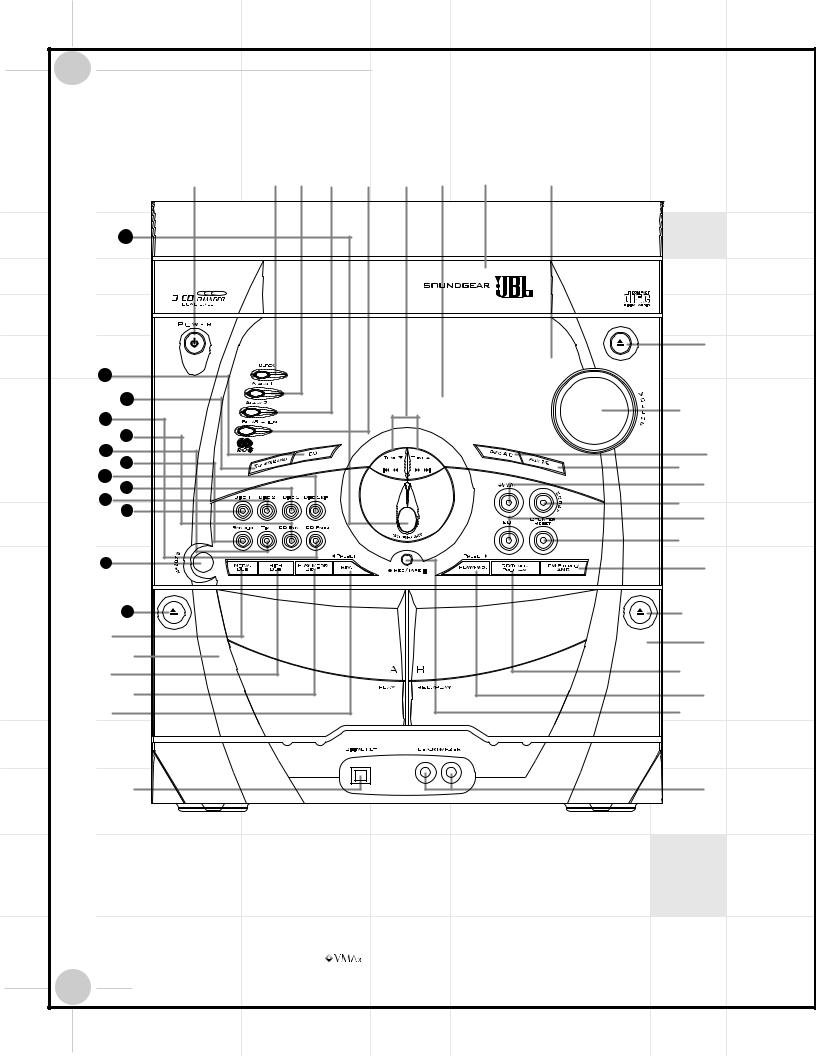
GETTING STARTED |
|
|
Controls and Connections |
|
|
Front Panel |
|
¡ |
™ £ ¢ § ¶ • |
ª |
43 |
|
|
|
|
‚ |
42 |
|
|
41 |
|
⁄ |
40 |
|
|
|
|
|
39 |
|
|
38 |
|
¤ |
37 |
|
|
|
‹ |
|
36 |
|
|
|
› |
|
35 |
|
|
34 |
|
fi |
33 |
|
|
|
fl |
|
|
|
|
|
|
‡ |
32 |
|
° |
|
|
|
31 |
|
· |
k |
|
a |
|
|
|
j |
|
b |
i |
|
|
|
|
|
h |
|
c |
g |
|
d |
f |
|
e |
¡ Power button |
¶ Display |
fi Boost button |
™ Clock button |
• CD Tray |
fl EQ Select button |
£ Alarm 1 button |
ª Remote Sensor |
‡ Counter Reset button |
¢ Alarm 2 button |
‚ CD Tray Open/Close button |
° FM Stereo/ANR (AM Noise |
Set/Station button |
⁄ Volume knob |
Reduction) button |
§ Tune Down/Up (AM/FM), |
¤ Tape A/B Select button |
· |
Tape Deck B Eject |
||
Fast Forward/Rewind (Tape), |
‹ Aux 1/2 Select button |
a |
Tape Deck B (Rec/Play) Door |
||
Skip/Search (CD) button |
› |
|
button |
b |
CD/Tuner Program button |
|
|||||
|
|
||||
4
|
|
|
|
GETTING STARTED |
|
|
||
|
|
|
|
|
|
|||
|
|
c Preset Up (AM/FM)/Forward Play |
Controls and Connections |
|
||||
|
|
k Normal Speed (Tape to Tape) |
|
Random button |
||||
|
|
37 |
||||||
|
|
(Tape)/Play (CD) button |
|
|
Dubbing button |
|
Time button |
|
|
|
|
|
38 |
||||
|
|
d Record/Pause (Tape) button |
|
31 |
Tape Deck A Eject |
|||
|
|
|
|
|||||
|
|
|
|
CD Sync (CD Synchro Dubbing) button |
||||
|
|
39 |
||||||
|
|
|
|
|
|
|
||
|
|
e Aux 1/MP3 Input jacks |
|
32 |
Headphones jack |
|
||
|
|
|
|
|||||
|
|
|
|
|
||||
|
|
40 |
CD Pause button |
|||||
|
|
f Optical Digital Output jack |
|
|
|
|
||
|
|
|
|
|
|
|||
|
|
|
|
|
|
|
||
|
|
|
|
|
|
|
||
|
|
|
|
|
|
|
41 |
Tuner/Band (AM/FM) button |
|
|
g Preset Down (AM/FM)/ |
CD Control Buttons: |
|
||||
|
|
42 |
CD Function button |
|||||
|
|
Reverse Play (Tape) button |
|
|||||
|
|
|
33 |
Disc 1 button: Disc Direct Play button |
43 |
Stop/Reset (Tape, CD, Tuner Presets) button |
||
|
|
h Play Mode/Demo button |
|
|||||
|
|
|
|
|
||||
|
|
|
|
|
|
|
||
|
|
i Hi-Speed (Tape to Tape) |
|
34 |
Disc 2 button: Disc Direct Play button |
|
|
|
|
|
|
|
|
|
|
||
|
|
|
35 |
Disc 3 button: Disc Direct Play button |
|
|
||
|
|
Dubbing button |
|
|
|
|||
|
|
|
|
Disc Skip button |
|
|
||
|
|
|
36 |
|
|
|||
|
|
|
|
|
|
|
||
|
|
j Tape Deck A (Play) Door |
|
|
|
|||
|
|
|
|
|
|
|
||
|
|
|
|
|
|
|
||
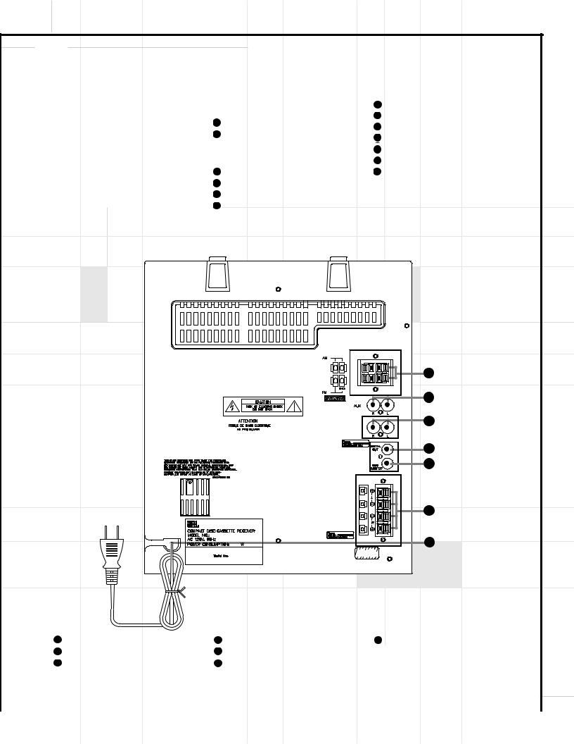
Rear Panel
44
45
2
46 (SG3030 Only)
SPEAKER CONNECTOR 1
47
48
49
50
SPEAKER
CONNECTOR 2
|
|
|
|
|
|
|
|
|
|
|
|
|
44 |
Antenna terminals |
47 |
Coaxial Digital Output jack |
50 |
Power Cord |
|||||
|
|
|
|
|
|
|
|
|
|
|
|
|
45 |
Aux 2 Input jacks |
48 |
Subwoofer Output jack |
|
|
|
|
|
|
|
|
|
|
|
|
|
|
|
|
|
||
|
|
|
|
|
|
|
|
|
|
|
|
46 |
Tweeter/Midrange Speaker Output |
49 |
Speaker Terminals (Model SG2020)/ |
|
|
|
|
|
|
|
|
|
|
|
|
|
|
|
|
|
|
||
|
|
jacks (Model SG3030 only) |
|
Speaker Woofer Section terminals |
|
|
|
|
|
|
|
|
|
|
|
(Model SG3030) |
|
|
|
5 |
|
|
|
|
|
|
|
|
|
|
|
|
|
||
|
|
|
|
|
|
|
|
|
|
|
|
|
|
|
|
|
|
|
|
|
|
|
|
 Loading...