

Page 1

JBL Synthesis
SDP-40 Serial Communications Protocol Printed on: 01/11/02
Serial Communications Protocol Definition
Project: SDP-40
Updated: January 11, 2002
Major rev 1
Minor rev 2
JBL Synthesis, Inc.
8500 Balboa Blvd.
Northridge, CA 91329
818-830-8757
© 2001 JBL Synthesis All rights reserved. 1 of 1
Page 2

JBL Synthesis
SDP-40 Serial Communications Protocol Printed on: 01/11/02
Manufactured under license from Dolby Laboratories. “Dolby”, “Pro Logic”, and the double-D symbol
are trademarks of Dolby laboratories.
Lucasfilm and THX are trademarks or registered trademarks of Lucasfilm, Ltd.
© Lucasfilm, Ltd. & TM. Surround EX is a jointly developed technology of THX and Dolby
Laboratories, Inc. and is a trademark of Dolby Laboratories, Inc. All rights reserved. Used under
authorization.
Manufactured under license from Digital Theater Systems, Inc. U.S. Pat. No. 5,451,942; 5,956,674;
5,974,380; 5,978,762 and other worldwide patents issued and pending. “DTS”, “DTS -ES Extended
Surround” and “Neo:6” are trademarks of Digital Theater Systems, Inc. © 1996, 2000 Digital Theater
Systems, Inc. All rights reserved.
“LOGIC7” and the LOGIC7 symbol are registered trademarks of Lerxicon, a Harman International
Company.
© 2001 JBL Synthesis, All rights reserved.
This document should not be construed as a commitment on the part of JBL Synthesis. The
information it contains is subject to change without notice. JBL Synthesis assumes no
responsibility for errors that may appear within this document.
JBL Synthesis, Inc.
8500 Balboa Blvd.
Northridge, CA 91329
Tel 818-830-8757
Fax 818-891-6894
www.jblsynthesis.com
Customer Support
Tel 818-830-8757
Fax 818-891-6894 (Sales & Service)
© 2001 JBL Synthesis All rights reserved. 2 of 2
Page 3

JBL Synthesis
SDP-40 Serial Communications Protocol Printed on: 01/11/02
1 Documents 5
2 Definitions 5
2.1 Protocol Version Cross-reference 5
3 Abbreviations 5
4 G eneral Description 5
5 Physical Layer 7
DB-9 RS232 Connector 7
5.2 Serial Port Driver 7
5.3 Errors 7
5.4 SDP-40 Receive Buffer 7
5.5 SDP-40 Hardware Verification (Not Supported in SDP-40 V1.00, V1.01) 7
6 Data Link Layer 8
6.1 Errors 8
7 Application Layer 9
7.1 SDP-40 Asynchronous Notification Packets 9
7.1.1 Wakeup Notification (SDP-40, SDP-3) 9
7.1.2 Sleep Notification (SDP-40, SDP-3) 9
7.1.3 Front Panel Display (SDP-40, SDP-3) 9
7.1.4 SDP-3 Parameter Change (SDP-40, SDP-3) 10
7.2 Acknowledgment Packets 12
7.2.1 Acknowledge (SDP-40, SDP-3) 12
7.2.2 No Acknowledge (SDP-40, SDP-3) 12
7.3 Host Initiated Command Packets 12
7.3.1 Reset Unit (SDP-40, SDP-3) 12
7.3.2 Restore (SDP-40, SDP-3) 13
7.3.3 SDP-3 Send IR Command (SDP-40, SDP-3) 13
7.3.4 Get Unit Configuration (SDP-40, SDP-3) 14
7.3.5 Get System Status (SDP-40, SDP-3) 17
7.3.6 Get Zone 2 Status (SDP-40, SDP-3) 18
7.3.7 Get System Parameter Definition (SDP-3) 20
7.3.8 Get System Parameter Values (SDP-3) 20
7.3.9 Get Effect Definition by Id (SDP-3) 20
7.3.10 Get Effect Parameter Definition (SDP-3) 20
7.3.11 Get Effect Parameter Values (SDP-3) 20
7.3.12 Get Custom Name (SDP-40, SDP-3) 20
7.3.13 Get Input Name by Id (SDP-40, SDP-3) 21
7.3.14 Get FPD Control Registers (SDP-3) 21
7.3.15 Set System Parameter Values (SDP-3) 22
7.3.16 Set Effect Parameter Values (SDP-3) 22
7.3.17 Set Effect Name by Effect Id (SDP-3) 22
7.3.18 Set System Volume (SDP-40, SDP-3) 22
7.3.19 Set Main Balance (SDP-40, SDP-3) 22
7.3.20 Set Front/Back Balance (SDP-40, SDP-3) 23
7.3.21 Set Active Effect by Id (SDP-40, SDP-3) 23
7.3.22 Set Record Input (SDP-40, SDP-3) 24
7.3.23 Clear Record Input (SDP-40, SDP-3) 25
© 2001 JBL Synthesis All rights reserved. 3 of 3
Page 4

JBL Synthesis
SDP-40 Serial Communications Protocol Printed on: 01/11/02
7.3.24 Set Zone2 Volume (SDP-40, SDP-3) 25
7.3.25 Set Zone2 Left/Right Balance (SDP-40, SDP-3) 26
7.3.26 Set Custom Name (SDP-40, SDP-3) 26
7.3.27 Set Input Name by Id (SDP-40, SDP-3) 27
7.3.28 Set FPD Control Registers (SDP-3) 27
7.3.29 Host Wakeup (SDP-40, SDP-3) 27
7.3.30 Host Sleep (SDP-40, SDP-3) 28
7.3.31 Get Communication Configuration (SDP-40, SDP-3) 28
7.3.32 Set Communication Configuration (SDP-40, SDP-3) 29
7.3.33 Set Mute (SDP-40, SDP-3) 29
7.3.34 Set Output Level Adjustments (SDP-3) 30
7.3.35 Send Display String Command (SDP-40, SDP-3) 30
7.3.36 SDP-40 Get Parameter by Id (SDP-40) 31
7.3.37 SDP-40 Set Parameter by Id (SDP-40) 33
7.3.38 SDP-40 Set Parameter by Id, No Run (SDP-40) 34
7.3.39 SDP-40 Get Unit Configuration (SDP-40) 35
7.3.40 SDP-40 Send IR Command (SDP-40) 38
7.3.41 SDP-40 Get Parameter Value by Id (SDP-40) 38
7.3.42 SDP-40 Set Parameter Notification by Id (SDP-40) 38
7.3.43 SDP-40 Parameter Notification by Id (SDP-40) 38
7.3.44 SDP-40 Parameter Get Value String(SDP-40) 38
Appendix A Command Codes 39
Appendix B Error Codes 41
Appendix C SDP-3 IR-Codes 43
Appendix D SDP-40 IR Codes 44
Appendix E SDP-3 Input Id’s 45
Appendix F SDP-40 Input Id's 45
Appendix G Protocol Constants 45
Appendix H SDP-40 Effect Id’s(Mode Id's) 46
Appendix I SDP-3 to SDP-40 Effect ID Map 47
Application Notes and Examples 48
7.4 Box initializations: 48
7.4.1 SDP-40: 48
7.4.2 HOST: 48
7.5 Getting System Wide Status and Setup: 48
7.5 Downloading the System Setup to the 48
7.6 SDP-40: 48
7.7 Simple System Control & System Status: 48
7.8 Examples: 49
7.8.1 SDP-40 Get Unit Configuration 49
7.8.2 Send SDP-3 IR Command Example 50
7.8.3 Send SDP-40 IR Command Example 51
© 2001 JBL Synthesis All rights reserved. 4 of 4
Page 5

JBL Synthesis
SDP-40 Serial Communications Protocol Printed on: 01/11/02
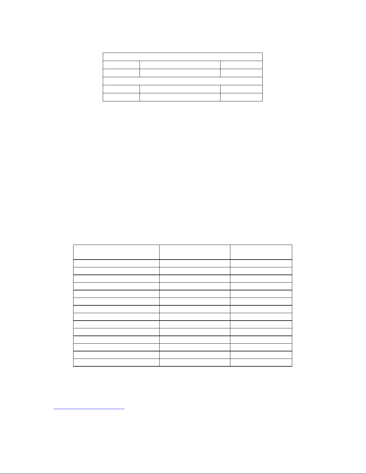
1 Documents
The following documents should also be used with this document to understand how this protocol can be
used with an SDP-40.
JBLSPD-3TECH, MANUAL, OWNER’S, SDP-3
SDP-3 Serial Port Definition, Protocol Version 1
070-14991rev 0 Manual, Owner’s, SDP-40
2 Definitions
User Parameter: A user changeable variable that stores a specific value that describes an
operating condition for the SDP-40 system.
HOST: The device initiating or receiving the serial communication packets to/from the
SDP-40.
SDP-40, SDP-3: The JBL Synthesis product receiving or transmitting the serial communication
packets to/from the HOST.
Nonvolatile RAM: The area of memory in an SDP-40 that stores users adjustable parameters. The
Nonvolatile RAM is battery backed, to maintain values during SDP-40 power
down.
2.1 Protocol Version Cross-reference
All references to SDP-40 shall be valid for both the SDP-40 and MC -12b products unless specifically
documented otherwise. All references to SDP-3 shall be valid for the SDP-3 and MC -1 products unless
specifically documented otherwise.
3 Abbreviations
SOP Start of Packet
EOP End of Packet
ACK Acknowledge
NAK No Acknowledge
FPD Front Panel Display
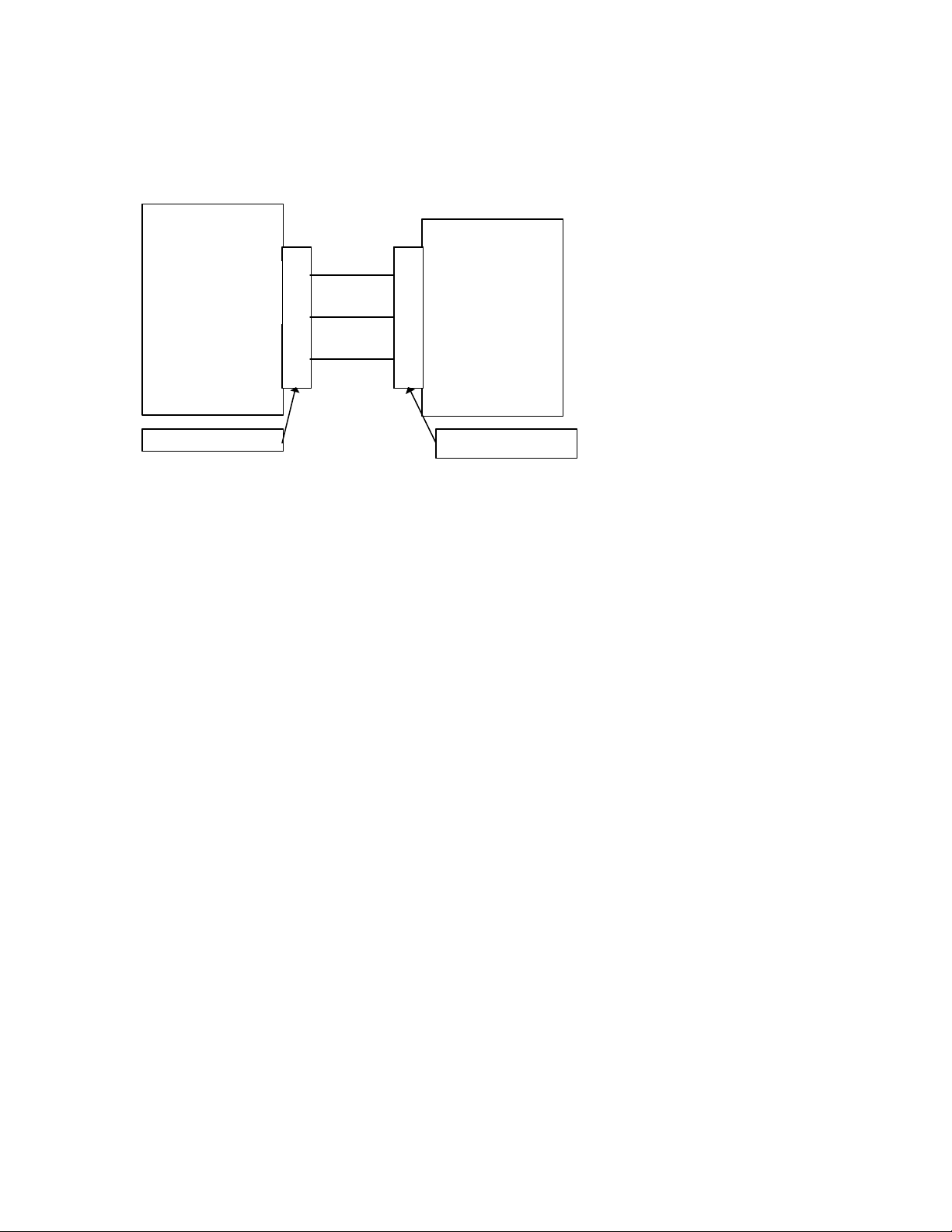
4 General Description
The intention of the SDP-40 serial port and protocol communication is for an external connected HOST to
control and obtain status from the SDP-40. The protocol has been designed to focus on two specific goals.
The first is HOST uploading and downloading of SDP-40 configuration, and system/effect setups. The
second is HOST control of basic user adjustable parameters. (i.e. input, volume, balance…)
HOST
Rs-232 Serial Link
JBL Synthesis
SDP-40
© 2001 JBL Synthesis All rights reserved. 5 of 5
Page 6

JBL Synthesis
SDP-40 Serial Communications Protocol Printed on: 01/11/02
The SDP-40 uses simple notification, command, response and acknowledgment packets to have
communication transactions with a given HOST. This protocol is designed for point to point
communication between a HOST and SDP-40. The SDP-40 Protocol is a 3 layered system. The SDP-40 serial
protocol allows for the SDP-40, or the HOST, to initiate a communication transaction. Most transactions are
initiated by the HOST. SDP-40 then responds to the HOST command with either a response or
acknowledgment packet. There are a few asynchronous notifications that SDP-40 initiates indicating system
changes. Each transaction initiated must wait for a corresponding response before initiating the next
transmission.
The 3 protocol layers are: Physical, Data Link, and Application Layers.
The SDP-40 Serial Protocol attempts to be as backward compatible with the SDP-3 as possible. This
document will try to inform the user/programmer of the consistencies and differences between the SDP-3
protocol and the SDP-40 protocol. The basic structure of the protocol has not changed. A number of
command/responses/notifications packets have been implemented exactly as they were in the SDP-3. These
commands may not fully exercise the functionality of the SDP-40 (i.e. SDP-3 has 8 inputs that have been
mapped to 8 of the 12 inputs on the SDP-40, SDP-3 IR codes are not the same as SDP-40 IR codes) In the
case of these commands additional SDP-40 commands have been added to fully implement the SDP-40
functionality. In addition, some of the inter nal structure of the SDP-40 has forced the protocol to be unable
to support some SDP-3 commands. These commands have been totally replaced with new commands that
provide more control over the SDP-40 than was capable in the SDP-3. (Parameter Set/Get commands)
Physical Layer (RS232)
Data Link Layer
Application Layer
© 2001 JBL Synthesis All rights reserved. 6 of 6
Page 7
JBL Synthesis
SDP-40 Serial Communications Protocol Printed on: 01/11/02
5 Physical Layer
5.1 DB-9 RS232 Connector
SDP-
COM1
Transmit Data
Receive Data
9 Pin D-Shell (female)
Note: The wiring requirements for a 9 pin to 9 pin serial connection, are a male to female straight through
cable.
Ground
2
3
5
Host
Receive Data
2
Transmit Data
3
Ground
5
9 Pin D-Shell (male)
5.2 Serial Port Driver
SDP-40 serial port has been setup to operate as follows:
Operating Mode: Full Duplex
Baud rate: 19.2K baud
Data Size: 8 bits (1 byte)
Parity: Odd
Stop Bits: 1
5.3 Errors
The SDP-40 will detect parity, framing and data overrun errors. If any of the physical layer error s are
detected, the complete packet is corrupted and the SDP-40 will reset the transaction and begin to look for a
start of packet byte.
5.4 SDP-40 Receive Buffer
The SDP-40 has an internal receive buffer. The buffer is 256 Bytes and will transmit a NAK packet with an
error code of DC_ERR_BUFFER_FULL to the HOST if the buffer is full. If the buffer is full, all data
transmitted to the SDP-40 will be ignored. Therefore, making the currently transmitted packet, if partially
transmitted invalid.
5.5 SDP-40 Hardware Verification (Not Supported in SDP-40 V1.00, V1.01)
This test verifies the RS232 ports are working by comparing the transmitted signal (at pin 2) to the received
signal (at pin 3). The SDP-40 transmits a known test signal just following a power up. The SDP-40 monitors
the serial port receivers while transmitting the test signal. If the signals are the same, the test passes. In
order to test this circuit, RS232 Wraparound plug(s) are needed and must be installed at the female D9
connector(s) on the rear panel of the SDP-40 labeled “RS232”. The wraparound plug shorts pins 2 to 3,
allowing for the SDP-40 to receive the signal it is transmitting. Once installed, power cycle the SDP-40 and
verify the following message is displayed on the FPD:
© 2001 JBL Synthesis All rights reserved. 7 of 7
Page 8
JBL Synthesis
SDP-40 Serial Communications Protocol Printed on: 01/11/02
SERIAL PORT A PASSED
SERIAL PORT B PASSED
This message is displayed for about 2 seconds before entering normal operating mode. If no messages are
displayed, then both wrap tests failed.
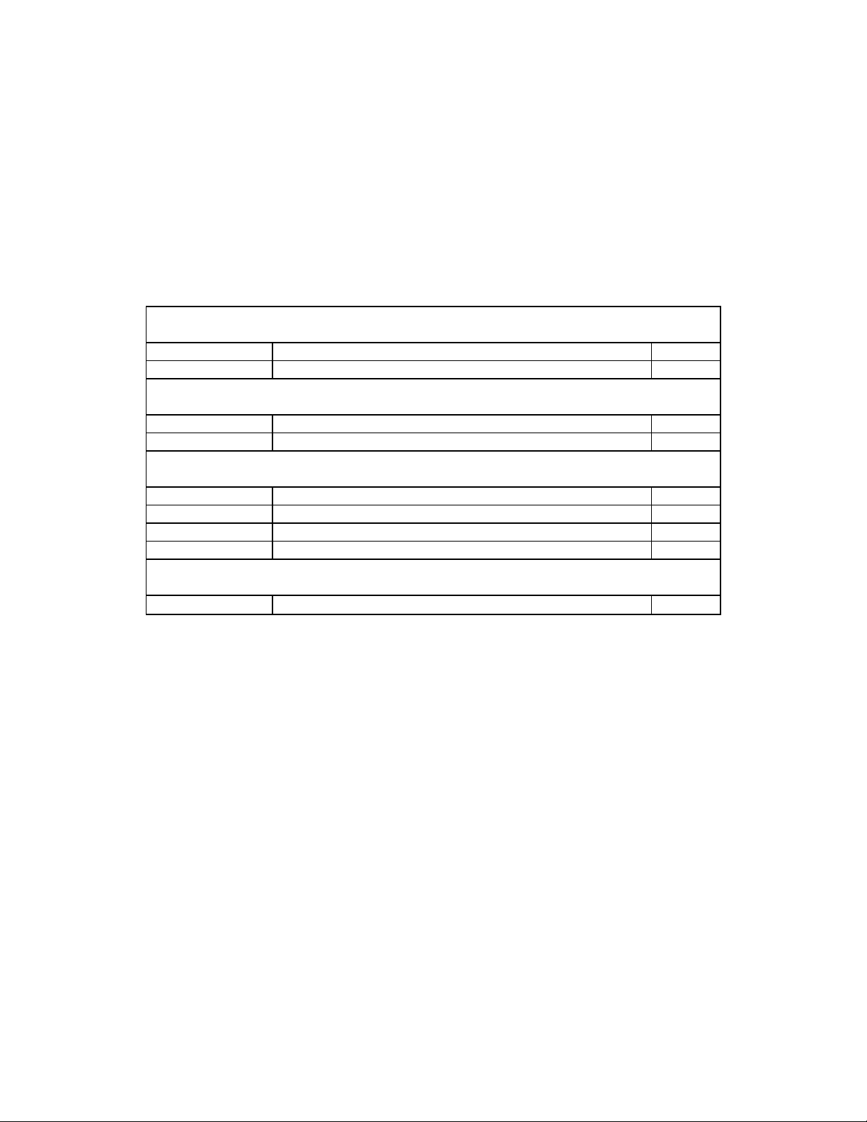
6 Data Link Layer
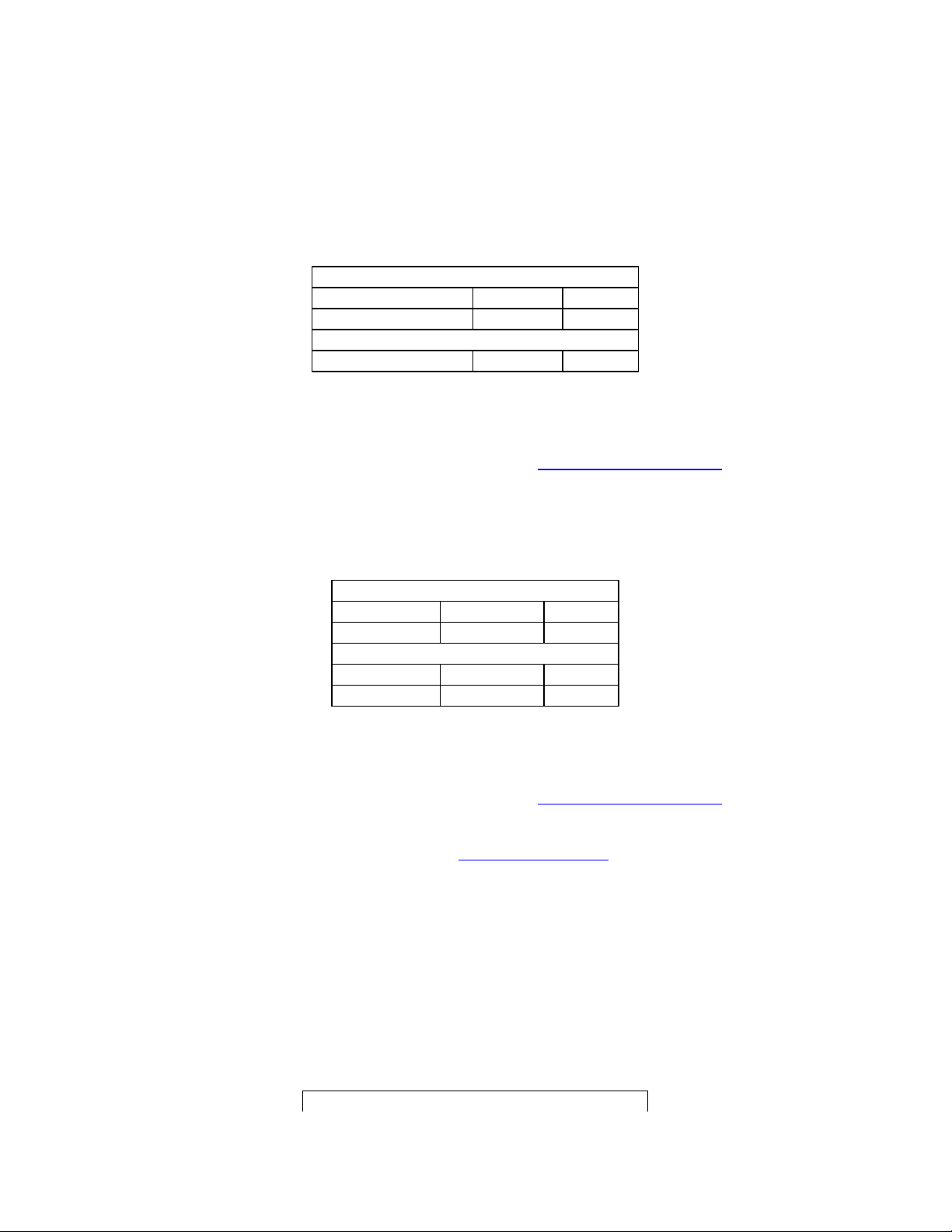
The data link layer is used to define a transmission packet. The layer appends a header and tail that
encloses the transmitted application packet data. The data link header will contain the start of packet byte
and count of bytes to follow. The data link tail will contain the end of packet byte.
Data Link Header:
Byte Number Description Value
First Byte(0) Start of Packet (SOP) 0xF1
Byte(1) DLL Data Count nn
Application Heade r:
Byte(2) Command nn
Byte(3) APP Data Count (number of application data bytes to Follow) nn
Application Data:
Byte(4) Data[0] nn
Byte(5) Data[1] nn
… Data[…] nn
Last Data Byte -1 Data[Data Count -1] nn
Data Link Tail:
Last Byte End of Packet (EOP) 0xF2
6.1 Errors
If the number of DLL data bytes received is the same as the data count and an EOP has not been received,
the SDP-40 responds by transmitting a NAK packet with an error code DC_ERR_INVALID_PACKET. The
SDP-40 then continues to look for a SOP byte and will not process the erroneous application packet. The
HOST can use this as an indicator to retransmit the corrupted packet.
In addition, each byte of a packet must be received sequentially and within the INTER_PACKET_TIME. If
any of the bytes within a packet transmission exceeds the INTER_PACKET_TIME, the SDP-40 will respond
by transmitting a NAK packet with an error code DC_ERR_INVALID_PACKET. The SDP-40 then
continues to look for a SOP byte and will not process the erroneous application packet. The HOST can use
this as an indicator to retransmit the corrupted packet.
© 2001 JBL Synthesis All rights reserved. 8 of 8
Page 9
JBL Synthesis
SDP-40 Serial Communications Protocol Printed on: 01/11/02
7 Application Layer
7.1 SDP-40 Asynchronous Notification Packets
SDP-40 has been designed to transmit the asynchronous notification packets following these system
changes:
1. Power On
2. Entering Standby
3. Front Panel Display update
4. Parameter Value Changes.
The notification packets are defined as follows:
7.1.1 Wakeup Notification (SDP-40, SDP-3)
By transmitting the Wakeup Notification, SDP-40 indicates the unit has just “powered on” or reset and is
ready to receive host commands. This notification is primarily for the HOST to know the status of the SDP-
40.
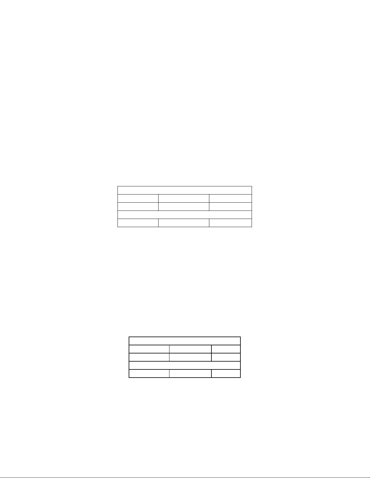
7.1.1.1 Notification Packet Description
Application Header:
Command DC_WAKEUP 0x01
Data Count 0 0x00
Application Data:
N/A
7.1.1.2 Host Response
The SDP-40 does not expect any response from the HOST.
7.1.2 Sleep Notification (SDP-40, SDP-3)
By transmitting the Sleep Notification, SDP-40 indicates the unit is shutting down into a standby mode.
Because the hard power switch could be activated independently of the SDP-40 system software, hard
power down will not be notified. Acknowledgment of the Sleep Notification is not required. This
notification is primarily for the HOST to know the operating status of the SDP-40.
7.1.2.1 Notification Packet Description
Application Header:
Command DC_SLEEP 0x02
Data Count 0 0x00
Application Data:
N/A
7.1.3 Front Panel Display (SDP-40, SDP-3)
SDP-40 will transmit the front panel display buffer following the update to the SDP-40 front panel display.
The SDP-40 front panel display is 2 X 20 ASCII character display. The HOST can control the operation of
this notification message by FPD internal control registers. Individual notifications can be enabled or
disabled and the minimum transmit interval can be adjusted. Transmission of the display buffer is
© 2001 JBL Synthesis All rights reserved. 9 of 9
Page 10
JBL Synthesis
SDP-40 Serial Communications Protocol Printed on: 01/11/02
asynchronous to other host/SDP-40 communicati on and will only transmit following the completion of any
communication exchanges in progress or pending. The FPD control register command packets are described
in section 7.3.14 Get FPD Control Registers.
7.1.3.1 Notification Packet Description
Application Header:
Command DC_FPD 0x03
Data Count 42 0x2A
Application Data:
Data[0] - Data[21] Line1 ch ch ch… 0x00
Data[22] - Data[42] Line2 ch ch ch … 0x00
7.1.3.2 Data Description
Line1
Data Type: Null (0x00) terminated ASCII character string.
Max Length: DISP_LINE_LENGTH defined in Appendix G Protocol Constants.
Line2
Data Type: Null (0x00) terminated ASCII character string.
Max Length: DISP_LINE_LENGTH defined in Appendix G Protocol Constants.
The SDP-40 includes 8 custom characters that are defined to display increments of a display block . (i.e.
Volume Bar) The custom characters are ASCII character codes 08 - 0F(hex). The codes are used as follows:
'08' - left 1 bar
'09' - left 2 bars
'0A' - left 3 bars
'0B' - left 4 bars
'0C' - Full Cell
'0D' - Underscore
'0E' - right 3 bars
'0F' - not in use
7.1.3.3 HOST Response
The SDP-40 does not expect any response from the HOST.
7.1.4 SDP-3 Parameter Change (SDP-40, SDP-3)
SDP-40 will transmit predetermined parameter change notifications. If a parameter value is changed due to
any user action or system action the SDP-40 will transmit the current value of the parameter that is changing.
This command has been maintained for backward compatibility with SDP-3. In order to maintain backward
compatibility, the SDP-40 Parameters have been mapped to the SDP-3 parameters as described in the
Supported System Parameters table listed below.
© 2001 JBL Synthesis All rights reserved. 10 of 10
Page 11
JBL Synthesis
SDP-40 Serial Communications Protocol Printed on: 01/11/02
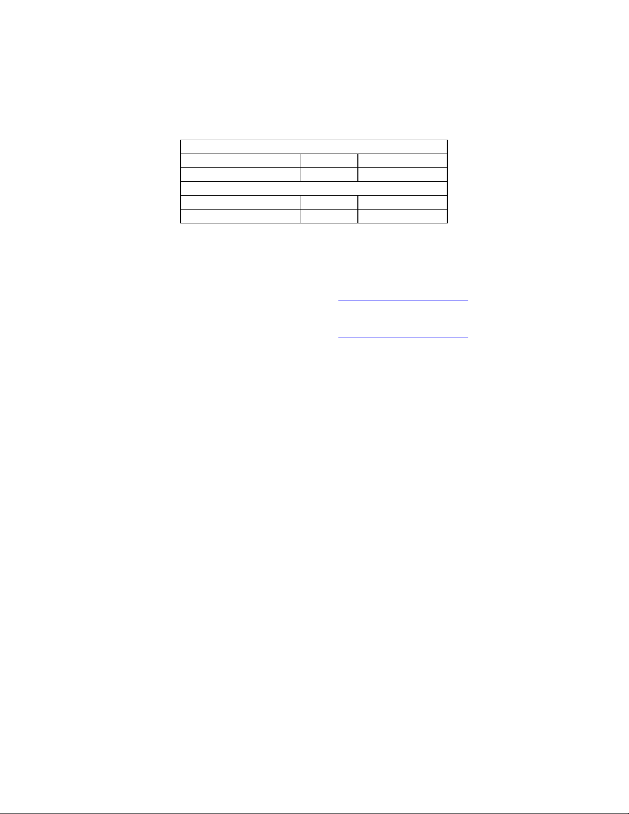
7.1.4.1 Notification Packet Description
Application Header:
Command DC_PARAM_CHG_MSG 0x04
Data Count 2 0x02
Application Data:
Data[0] ParamId nn
Data[1] Value nn
7.1.4.2 Data Description
ParamId:
Data Type: Unsigned 8 bit integer
Max: 255.
Value:
The Current Value for this system parameter.
Data Type: Unsigned 8 bit integer
Max: Set by the Max Value per the Parameter Definition response Packet for
the Parameter Id of this packet.
7.1.4.3 HOST Response
The SDP-40 does not expect any response from the HOST.
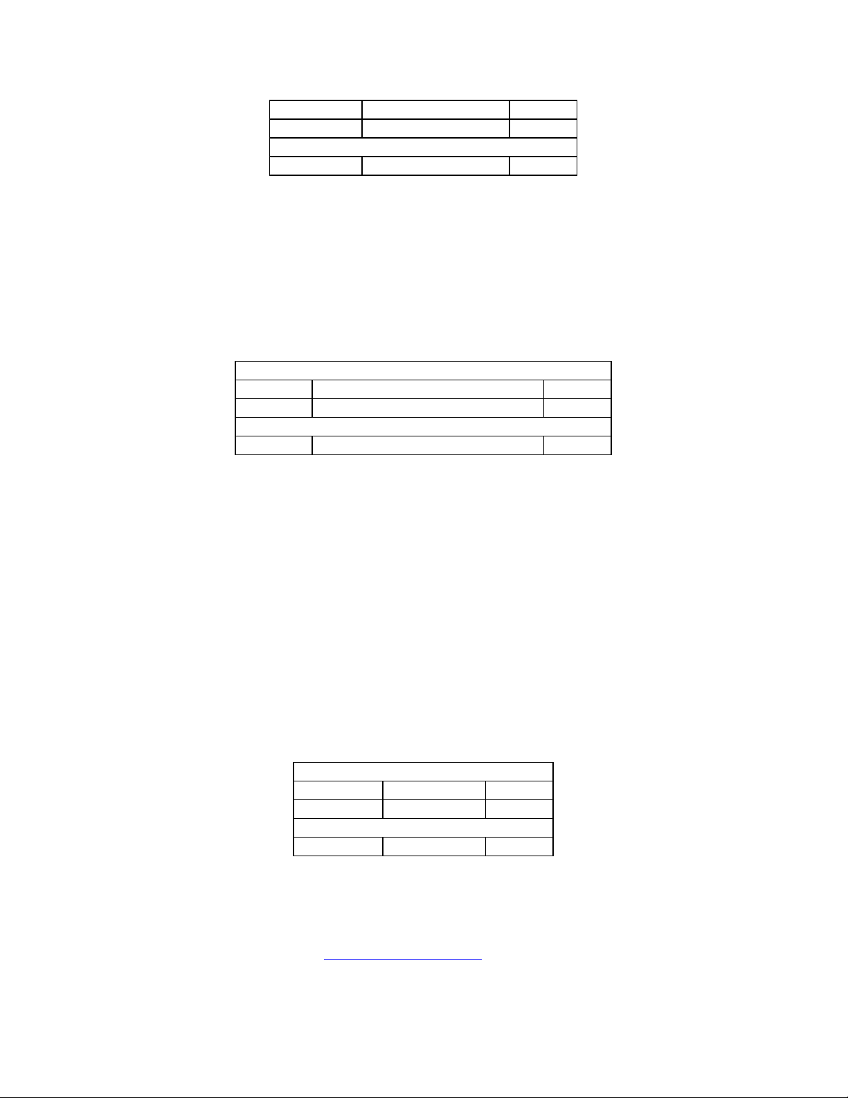
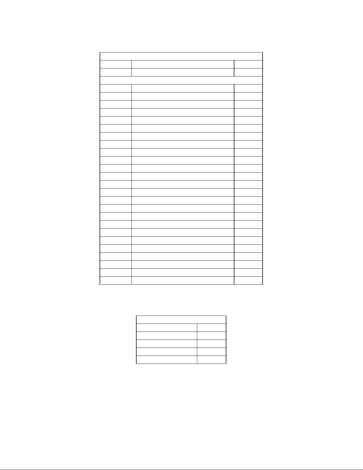
7.1.4.4 Supported System Parameters
The following parameters will be supported by this Parameter Change Notification:
Parameter SDP-40 Parameter
Name
Current Effect PROGRAM 1
Mute MUTE 3
System Volume VOLUME 5
Balance LR_BALANCE 6
Input Selection INPUT 7
Record/Zone 2 On/Off RECORD_ENABLED 18
Zone 2 Volume Z2_VOL 154
Zone 2 Balance Z2_BAL 156
Zone 2 Mute Z2_MUTE 157
Bass BASS 167
Treble TREBLE 168
Loudness LOUDNESS 169
Tilt TILT 174
Menu Background On/Off MENU_BKGND 190
Note: The Record/Zone 2 On/Off only applies to the SDP-40 Record zone. The Zone 2 Volume, Zone 2
Balance and Zone 2 Mute only apply to the SDP-40 Zone-2.
For Input Parameter Change Notifications the Input Value is a SDP-40 to SDP-3 input mapping, as shown in
Appendix F SDP-40 Input Id's.
SDP-3
ParamId(V4.00)
© 2001 JBL Synthesis All rights reserved. 11 of 11
Page 12
JBL Synthesis
1
SDP-40 Serial Communications Protocol Printed on: 01/11/02
7.2 Acknowledgment Packets
Acknowledge and No Ack nowledge packets are used to communicate transmission, packet and data
validation status. Both the HOST and SDP-40 can transmit and receive these packets.
7.2.1 Acknowledge (SDP-40, SDP-3)
7.2.1.1 Packet Description
Application Header:
Command DC_ACK 0xE0
Data Count
Application Data:
Data[0] Command nn
7.2.1.2 Data Description
Command:
DataType: Valid SDP-40 command as defined in Appendix A Command Codes.
0x01
7.2.2 No Acknowledge (SDP-40, SDP-3)
7.2.2.1 Packet Description
Application Header:
Command DC_NACK 0xE1
Data Count 20x02
Application Data:
Data[0] Command nn
Data[1] ErrorCode nn
7.2.2.2 Data Description
Command:
DataType: Valid SDP-40 command as defined in Appendix A Command Codes.
ErrorCode:
DataType: Error code as defined in Appendix B Error Codes.
7.3 Host Initiated Command Packets
The SDP-40 serial communication protocol has been designed to respond to the following commands as
described below. Each command is transmitted to the SDP-40 with the identified parameters. If the
command is successfully received and processed by the SDP-40, the unit will respond with the described
response packet or action.
7.3.1 Reset Unit (SDP-40, SDP-3)
Commands the SDP-40 to soft reset.
7.3.1.1 Command Packet Description
Application He ader:
© 2001 JBL Synthesis All rights reserved. 12 of 12
Page 13
JBL Synthesis
SDP-40 Serial Communications Protocol Printed on: 01/11/02
Command DC_CMD_RESET 0x10
Data Count 0 0x00
Application Data:
N/A
7.3.1.2 SDP-40 Response
The SDP-40 will perform an internal reset. After reset the SDP-40 will go through a soft power -up
initialization. This includes transmitting the “Wakeup Notification Packet”. A soft reset does not reinitialize
the SDP-40. Nonvolatile RAM is maintained.
7.3.2 Restore (SDP-40, SDP-3)
Commands the SDP-40 to restore the system and effect parameters to the factory defaults.
7.3.2.1 Command Packet Description
Application Header:
Command DC_CMD_RESTORE_DEFAULTS 0x13
Data Count 0 0x00
Application Data:
N/A
7.3.2.2 SDP-40 Response
The SDP-40 will reset, clear any saved system and effect parameters in Nonvolatile RAM, and restore the
factory default system and effect parameters. After reset the SDP-40 will go through a soft power -up
initialization. This includes transmitting the “Wakeup Notification Packet”.
7.3.3 SDP-3 Send IR Command (SDP-40, SDP-3)
Transmits SDP-3 IR command key codes to the SDP-40.
This command has been maintained for backward compatibility to the SDP-3. The SDP-3 IR code
functionality has been mapped to the SDP-40 IR code functionality as per the SDP-3 to SDP-40 IR code
table.
7.3.3.1 Command Packet Description
Application Header:
Command DC_CMD_IR 0x14
Data Count 1 0x01
Application Data:
Data[0] KeyCode nn
7.3.3.2 Data Description
KeyCode:
Data Type: Unsigned 8 bit integer.
Valid Values: Appendix C SDP-3 IR-Codes
7.3.3.3 SDP-40 Response
© 2001 JBL Synthesis All rights reserved. 13 of 13
Page 14
JBL Synthesis
SDP-40 Serial Communications Protocol Printed on: 01/11/02
The KeyCode is processed as a valid IR code. No acknowledgment will be sent from SDP-40.
7.3.3.4 Data Validation
The KeyCode data will be verified as a legal IR code. If the Code is not valid the SDP-40 will not respond.
7.3.4 Get Unit Configuration (SDP-40, SDP-3)
This command is supported for backward compatibility. SDP-40 users should be using paragraph " 7.3.39
SDP-40 Get Unit Configuration (SDP-40)" The Request to SDP-40 for it’s current unit configuration. SDP-40
will respond with “Unit Configuration Packet”. The HOST should use this information to determine if any
information saved by the HOST is cur rent.
7.3.4.1 Command Packet Description
Application Header:
Command DC_CMD_GET_CONFIG 0x15
Data Count 0 0x00
Application Data:
N/A
© 2001 JBL Synthesis All rights reserved. 14 of 14
Page 15
JBL Synthesis
SDP-40 Serial Communications Protocol Printed on: 01/11/02
7.3.4.2 SDP-40 Unit Configuration Response Packet
Application Header:
Command DC_RESP_UNIT_CONFIG 0x80
Data Count 25 0x19
Application Data:
Data[0] ProductId nn
Data[1] Software Type nn
Data[2] Software Level nn
Data[3] Software Major Revision nn
Data[4] Software Minor Revision nn
Data[5] Protocol Major Revision nn
Data[6] Protocol Minor Revision nn
Data[7] N/A nn
Data[8] Total Number of Effects nn
Data[9] TimeStamp[0] ch
Data[10] TimeStamp[1] ch
Data[11] TimeStamp[2] ch
Data[12] TimeStamp[3] ch
Data[13] TimeStamp[4] ch
Data[14] TimeStamp[5] ch
Data[15] TimeStamp[6] ch
Data[16] TimeStamp[7] ch
Data[17] TimeStamp[8] ch
Data[18] TimeStamp[9] ch
Data[19] TimeStamp[10] ch
Data[20] TimeStamp[11] ch
Data[21] TimeStamp[12] ch
Data[22] TimeStamp[13] ch
Data[23] TimeStamp[14] ch
Data[24] TimeStamp[15] 0x00
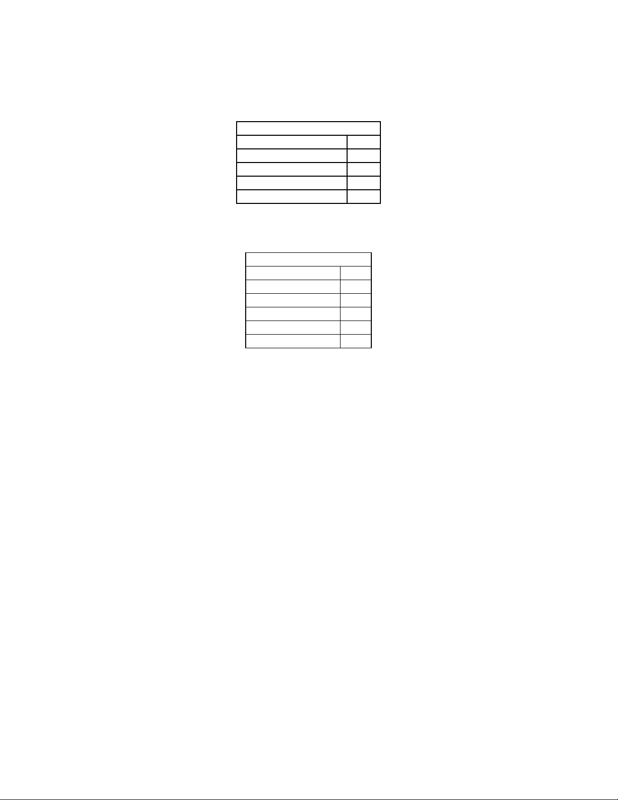
7.3.4.3 Data Description
ProductId: This unsigned 8 bit value describes the product.
Product ID
Lexicon DC-2 1
Lexicon MC-1 2
JBL Synthesis SDP -3 3
Lexicon MC-12 4
JBL Synthesis SDP-40
© 2001 JBL Synthesis All rights reserved. 15 of 15
5
Page 16
JBL Synthesis
SDP-40 Serial Communications Protocol Printed on: 01/11/02
Software Type: An unsigned 8 bit value indicating the current configuration of the unit’s
software. The following table shows the values assigned to the available types:
SW Type
THX 1
AC3 2
DTS 3
COMPLETE 4
BOOTROM 5
Software Level: The following table shows the values assigned to the possible software levels:
SW Level
RELEASED 0
PRE_ALPHA 1
ALPHA 2
BETA 3
GAMMA 4
UNSUPPORTED 5
*Note: SW level indicates the status of the SDP-40 internal application software.
Software Major Revision: An unsigned integer value indicating the unit’s major software version. The
host should use this information to determine if new effects, effect parameters, or
system parameters have been added or removed.
Software Minor Revision: An unsigned integer value indicating this units minor software version. Indicates
the units software operation has changed but effects, effect parameters, or
system parameters have not changed.
Protocol Major Revision: An unsigned integer value indicating the serial communication protocol major
version. The host should use this value to determine if new commands,
notifications, or response packets have been added or deleted from this
specification.
Protocol Minor Revision: An unsigned integer value indicating the serial communication protocol minor
version. The host should use this value to determine if the exist ing commands,
notifications, or response packets have changed in this specification
Total Number of Effects: An unsigned integer value indicating the maximum number of effects available
for this version of software. This should be used to determine the maximum
EffectId used in the “Get Effect Definition Packet”, “Get Effect Parameter
Definition Packet”, “Set Effect Name Packet” , and “Set Effect Parameter Values
Packet”.
TimeStamp: Is a null terminated ASCII text string describing the build date and time of the
current software build. The Format of this text string is:
“yy/mm/dd(sp)hh:mm”
yy- is the last two digits of the year (i.e. year 1999 = 99, year 2000 = 00)
© 2001 JBL Synthesis All rights reserved. 16 of 16
Page 17

JBL Synthesis
SDP-40 Serial Communications Protocol Printed on: 01/11/02
mm - is the month
dd- is the day
(sp) - is an ASCII space character (0x20)
hh - is the hour
mm - is the minute
7.3.5 Get System Status (SDP-40, SDP-3)
Request to SDP-40 for it’s current system status. SDP-40 will respond with “System Status Packet”.
7.3.5.1 Command Packet Description
Application Header:
Command DC_CMD_GET_SYS_STATUS 0x16
Data Count 0 0x00
Application Data:
N/A
7.3.5.2 System Status Response Packet
Application Header:
Command DC_RESP_SYS_STATUS 0x81
Data Count 10 0x0A
Application Data:
Data[0] System Volume nn
Data[1] Current Input nn
Data[2] Current EffectId (Mode) nn
Data[3] Current Input Sample Rate nn
Data[4] Current Input Format nn
Data[5] Mute Active nn
Data[6] TBD nn
Data[7] Left/Right Balance nn
Data[8] Front/Back Balance nn
Data[9] Video Synch nn
7.3.5.3 Data Description
System Volume:
Data Type: Unsigned 8 bit integer.
Maximum Value: 92
Conversion: 0 = -80 dB
92 = +12 dB
Current Input:
Data Type: Unsigned 8 bit integer.
Definition: Appendix F SDP-40 Input Id’s
Current EffectId(ModeId):
Data Type: Unsigned 8 bit integer.
Maximum Value: Appendix H SDP-40 Effect Id’s(Mode Id's)
© 2001 JBL Synthesis All rights reserved. 17 of 17
Page 18

JBL Synthesis
SDP-40 Serial Communications Protocol Printed on: 01/11/02
Current Input Sample Rate
Data Type: Unsigned 8 bit integer.
SAMPLE RATE
RATE_UNKNOWN 0
RATE_44 1
RATE_48 2
RATE_88 3
RATE_96 4
Current Input Format:
Data Type: Unsigned 8 bit integer.
DATA STREAM TYPE
DATA_TYPE_UNKNOWN 0
DATA_TYPE_BYPASS 1
DATA_TYPE_ANALOG 2
DATA_TYPE_PCM 3
DATA_TYPE_DD 4
DATA_TYPE_DTS 5
DATA_TYPE_NOISE 6
Mute Active:
Data Type: Boolean.
TRUE: System Mute is Active
FALSE: System is unmuted.
Left/Right Balance:
Data Type: Unsigned 8 bit integer.
Maximum Value: 32
Conversion: 0 = Left
16 = Center
32 = Right
Front/Back Balance:
Data Type: Unsigned 8 bit integer.
Maximum Value: 32
Conversion: 0 = Front
16 = Center
32 = Back
Video Synch:
Data Type: Boolean.
TRUE: SDP-40 has detected Video Sync for current video input
FALSE: SDP-40 can not detect Video Sync for the current video input
7.3.6 Get Zone 2 Status (SDP-40, SDP-3)
This command is a request to SDP-40 for current Zone 2 Status. SDP-40 will respond with “Zone2 Status
Packet”.
© 2001 JBL Synthesis All rights reserved. 18 of 18
Page 19

JBL Synthesis
SDP-40 Serial Communications Protocol Printed on: 01/11/02
7.3.6.1 Command Packet Description
Application Header:
Command DC_CMD_GET _ZONE2_STATUS 0x17
Data Count 0 0x00
Application Data:
N/A
7.3.6.2 Zone2 Status Response Packet
Application Header:
Command DC_RESP_ZONE2_STATUS 0x82
Data Count 5 0x05
Application Data:
Data[0] Zone2 Volume nn
Data[1] Assigned Zone 2 Input nn
Data[2] Zone2 Mute Active nn
Data[3] Record Active nn
Data[4] Zone2 Balance nn
7.3.6.3 Data Description
Zone2 Volume:
Data Type: Unsigned 8 bit integer.
Maximum Value: 92
Conversion: 0 = -80 dB
92 = +12 dB
Assigned Zone 2 Input:
Indicates the Zone 2 input that is currently assigned for the zone 2 outputs.
Data Type: Unsigned 8 bit integer.
Definition: Appendix F SDP-40 Input Id's
Zone2 Mute Active:
Data Type: Boolean.
TRUE: Zone2 Outputs are active.
FALSE: Zone 2 Outputs are not active.
Record Active:
Data Type: Boolean.
TRUE: Record Zone Output is active
FALSE: Record Zone Output is not Active.
© 2001 JBL Synthesis All rights reserved. 19 of 19
Page 20

JBL Synthesis
SDP-40 Serial Communications Protocol Printed on: 01/11/02
Zone 2 Balance:
Data Type: Unsigned 8 bit integer.
Maximum Value: 32
Conversion: 0 = Left
32 = Right
7.3.7 Get System Parameter Definition (SDP-3)
This command is not supported by the SDP-40.
7.3.8 Get System Parameter Values (SDP-3)
This command is not supported by the SDP-40.
7.3.9 Get Effect Definition by Id (SDP-3)
This command is not supported by the SDP-40.
7.3.10 Get Effect Parameter Definition (SDP-3)
This command is not supported by the SDP-40.
7.3.11 Get Effect Parameter Values (SDP-3)
This command is not supported by the SDP-40.
7.3.12 Get Custom Name (SDP-40, SDP-3)
Request to SDP-40 for an effect definition. SDP-40 will respond with “Custom Name Packet”.
7.3.12.1 Command Packet Description
Application Header:
Command DC_CMD_GET_CUST_NAME 0x2B
Data Count 0 0x00
Application Data:
N/A
7.3.12.2 Data Description
N/A
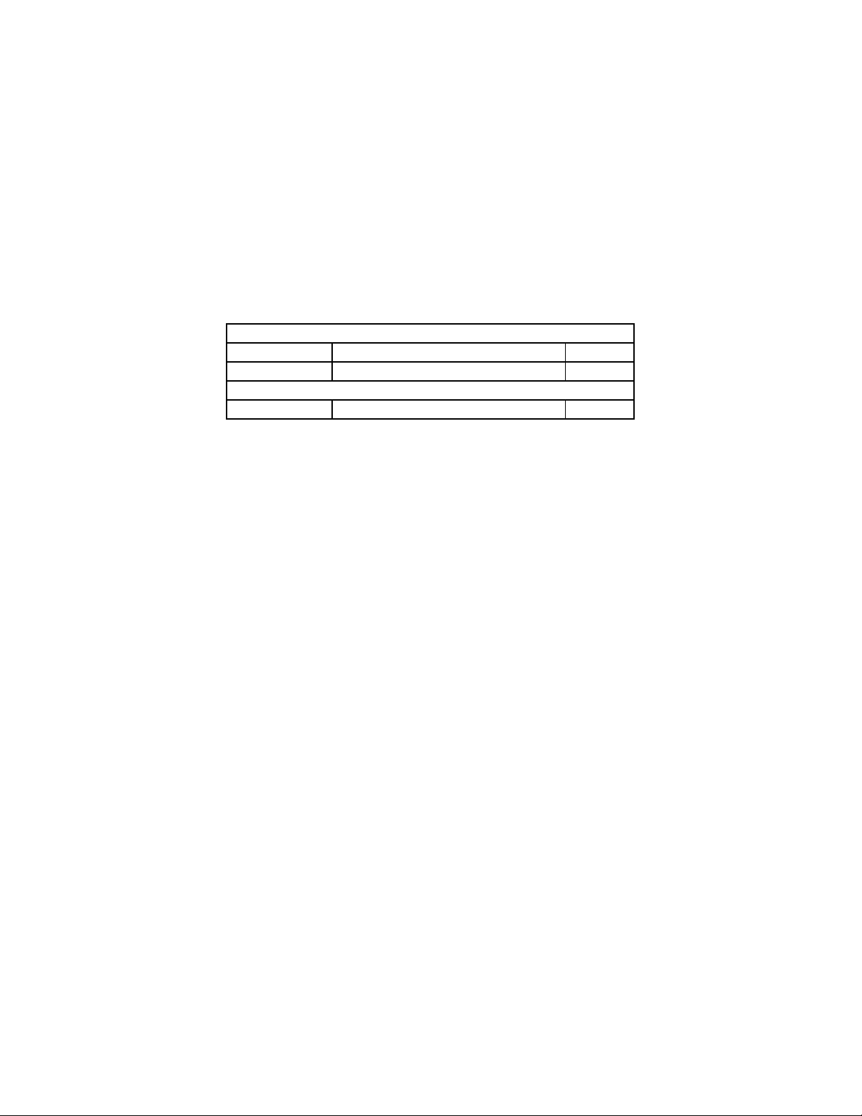
7.3.12.3 Custom Name Response Packet
Application Header:
Command DC_RESP_CUST_NAME 0x89
Number of Characters in
Data Count
Application Data:
Data[0]- Data[DataCount -1] CustomName ch ch ch … 0x00
CustomName + 1 nn
7.3.12.4 Data Description
CustomName:
Data Type: Null (0x00) terminated ASCII character string.
© 2001 JBL Synthesis All rights reserved. 20 of 20
Page 21

JBL Synthesis
SDP-40 Serial Communications Protocol Printed on: 01/11/02
Max Length: CUSTOM_NAME_LENGTH defined in Appendix G Protocol Constants.
7.3.13 Get Input Name by Id (SDP-40, SDP-3)
This command is a request to SDP-40 for the custom input name. SDP-40 will respond with “Input Name
Packet”.
7.3.13.1 Command Packet Description
Application Header:
Command DC_CMD_GET_INPUT_NAME 0x2D
Data Count 1 0x01
Application Data:
Data[0] InputId nn
7.3.13.2 Data Description
InputId:
Data Type: Unsigned 8 bit Integer
Max Value: 7
Conversion: Input Id are defined in Appendix F SDP-40 Input Id’s
7.3.13.3 Data Validation:
The InputId must be a valid Input number. If it is not the SDP-40 will respond with a NAK packet and error
code DC_INVALID_INPUT .
7.3.13.4 Input Name Response Packet
Application Header:
Command DC_RESP_INPUT_NAME 0x8A
Number of Characters in
Data Count
Application Data:
Data[0] InputId nn
Data[1]- Data[DataCount -1] InputName ch ch ch … 0x00
InputName + 2 nn
7.3.13.5 Data Description
InputId:
Data Type: Unsigned 8 bit Integer
Max Value: 7
Conversion: Input Id are defined in Appendix F SDP-40 Input Id’s
InputName:
Data Type: Null (0x00) terminated ASCII character string.
Max Length: INPUT_NAME_LENGTH defined in Appendix G Protocol Constants.
7.3.14 Get FPD Control Registers (SDP-3)
This command is not supported by the SDP-40.
© 2001 JBL Synthesis All rights reserved. 21 of 21
Page 22

JBL Synthesis
SDP-40 Serial Communications Protocol Printed on: 01/11/02
7.3.15 Set System Parameter Values (SDP-3)
This command is not supported by the SDP-40.
7.3.16 Set Effect Parameter Values (SDP-3)
This command is not supported by the SDP-40.
7.3.17 Set Effect Name by Effect Id (SDP-3)
This command is not supported by the SDP-40.
7.3.18 Set System Volume (SDP-40, SDP-3)
This command is a request to the SDP-40 to set the system volume with the value in this packet.
7.3.18.1 Command Packet Description
Application Header:
Command DC_CMD_SET_SYS_VOLUME 0x21
Data Count 1 0x01
Application Data:
Data[0] Value nn
7.3.18.2 Data Description
Value:
Data Type: Unsigned 8 bit integer.
Max: 92
Conversion: 0 = -80 dB
92 = +12 dB
7.3.18.3 SDP-40 Response
The SDP-40 will assign the value from the packet to the system volume.
7.3.18.4 Data Validation
If a value is passed that exceeds the maximum value of that parameter the SDP-40 will ignore the command
and transmit a DC_NAK command with an error code DC_INVALID_DATA.
7.3.19 Set Main Balance (SDP-40, SDP-3)
Commands SDP-40 to set the system balance to the value in this packet.
7.3.19.1 Command Packet Description
Application Header:
Command DC_CMD_SET_SYS_BALANCE 0x22
Data Count 1 0x01
Application Data:
Data[0] Value nn
© 2001 JBL Synthesis All rights reserved. 22 of 22
Page 23

JBL Synthesis
SDP-40 Serial Communications Protocol Printed on: 01/11/02
7.3.19.2 Data Description
Value:
Data Type: Unsigned 8 bit integer.
Maximum Value: 32
Conversion: 0 = Left
16 = Center
32 = Right
7.3.19.3 SDP-40 Response
The SDP-40 will assign the value from the packet to the system balance.
7.3.19.4 Data Validation
If a value is passed that exceeds the maximum value of that parameter the SDP-40 will ignore the command
and transmit a DC_NAK command with an error code DC_INVALID_DATA.
7.3.20 Set Front/Back Balance (SDP-40, SDP-3)
Commands SDP-40 to set the front/back balance to the value in this packet.
7.3.20.1 Packet Description
Application Header:
Command DC_CMD_SET_FRONT_BACK_BALANCE 0x23
Data Count 1 0x01
Application Data:
Data[0] Value nn
7.3.20.2 Data Description
Value:
Data Type: Unsigned 8 bit integer.
Max: 32
Conversion: 0 = Front
16 = Center
32 = Back
7.3.20.3 SDP-40 Response
The SDP-40 will assign the value from the packet to the front/back balance.
7.3.20.4 Data Validation
If a value is passed that exceeds the maximum value of that parameter the SDP-40 will ignore the command
and transmit a NAK command with an error code DC_INVALID_DATA.
7.3.21 Set Active Effect by Id (SDP-40, SDP-3)
This command requests the SDP-40 to set the active effect to the value in this packet. This command is
available for backward compatibility to the SDP-3. The SDP-3 Effect Id’s have been mapped to the SDP-40
Effect Ids as shown in Appendix H SDP-40 Effect Id's.
© 2001 JBL Synthesis All rights reserved. 23 of 23
Page 24

JBL Synthesis
SDP-40 Serial Communications Protocol Printed on: 01/11/02
7.3.21.1 Command Packet Description
Application Header:
Command DC_CMD_SET_EFFECT 0x24
Data Count 1 0x01
Application Data:
Data[0] EffectId nn
7.3.21.2 Data Description
EffectId:
Data Type: Unsigned 8 bit integer
Max: As shown in Appendix H SDP-40 Effect Id’s
Effect ID SDP-3 to SDP-40 Mapping is shown in Appendix I SDP-3 to SDP-40 Effect ID Map.
7.3.21.3 SDP-40 Response
The SDP-40 will load the desired effect.
7.3.21.4 Data Validation
If a value is passed that exceeds the maximum value of that parameter the SDP-40 will ignore the command
and transmit a NAK command with an error code DC_INVALID_DATA.
7.3.22 Set Record Input (SDP-40, SDP-3)
Sets the Record input. If Record was inactive, this command will set the input then activate the Record
function.
7.3.22.1 Command Packet Description
Application Header:
Command DC_CMD_SET_REC_INPUT 0x25
Data Count 1 0x01
Application Data:
Data[0] InputId nn
7.3.22.2 Data Description
InputId:
Data Type: Unsigned 8 bit Integer
Max Value: 7
Conversion: Input Id’s are defined in Appendix F SDP-40 Input Id's
7.3.22.3 SDP-40 Response:
If the Input Id is a valid SDP-40 input then the SDP-40 will make the request Input the active record input.
7.3.22.4 Data Validation:
The InputId must be a valid Input Id. If it is not the SDP-40 will respond with a NAK packet and error code
DC_INVALID_INPUT . If the input selection is disallowed (input blocked, digital input not selected…) SDP-
© 2001 JBL Synthesis All rights reserved. 24 of 24
Page 25

JBL Synthesis
SDP-40 Serial Communications Protocol Printed on: 01/11/02
40 will respond with a NAK packet and error code DC_INVALID_INPUT. If the input is assigned the SDP-40
will respond with an ACK Packet.
7.3.23 Clear Record Input (SDP-40, SDP-3)
Clears or Unassign’s the Record input. If Record is active, this command will set the Record Input to OFF
7.3.23.1 Packet Description
Application Header:
Command DC_CMD_CLEAR_REC_INPUT 0x26
Data Count 1 0x01
Application Data:
Data[0] InputId nn
7.3.23.2 Data Description
InputId:
This value is not used by SDP-40.
Data Type: Unsigned 8 bit Integer
7.3.23.3 SDP-40 Response
The SDP-40 will set the active record input to OFF.
7.3.23.4 Data Validation
The InputId is not used.
7.3.24 Set Zone2 Volume (SDP-40, SDP-3)
Commands SDP-40 to set the Zone 2 volume with the value in this packet.
7.3.24.1 Command Packet Description
Application Header:
Command DC_CMD_SET_ZONE2_VOLUME 0x27
Data Count 1 0x01
Application Data:
Data[0] Value nn
7.3.24.2 Data Description
Value:
Data Type: Signed 8 bit integer.(2’s Compliment)
Min: -80 dB (0xB0)
Max: +6 dB (0x06)
7.3.24.3 SDP-40 Response
The SDP-40 will assign the value from the packet to the Zone 2 volume.
7.3.24.4 Data Validation
If a value is passed that exceeds the maximum value of that parameter the SDP-40 will ignore the command
and transmit a NAK command with an error code DC_INVALID_DATA.
© 2001 JBL Synthesis All rights reserved. 25 of 25
Page 26

JBL Synthesis
SDP-40 Serial Communications Protocol Printed on: 01/11/02
7.3.25 Set Zone2 Left/Right Balance (SDP-40, SDP-3)
Commands SDP-40 to set the Zone 2 balance to the value in this packet.
7.3.25.1 Packet Description
Application Header:
Command DC_CMD_SET_ZONE2_BALANCE 0x28
Data Count 1 0x01
Application Data:
Data[0] Value nn
7.3.25.2 Data Description
Value:
Data Type: Signed 8 bit integer.(2’s Compliment)
Min: -16 (0xF0) Max Left
Max: +16 (0x10) Max Right
7.3.25.3 SDP-40 Response
The SDP-40 will assign the value from the packet to the Zone 2 balance.
7.3.25.4 Data Validation
If a value is passed that exceeds the maximum value of that parameter the SDP-40 will ignore the command
and transmit a NAK command with an error code DC_INVALID_DATA.
7.3.26 Set Custom Name (SDP-40, SDP-3)
Sets the Custom Name that can be displayed when the unit powers up.
7.3.26.1 Packet Description
Application Header:
Command DC_CMD_SET_CUST_NAME 0x2C
Number of characters in
Data Count
Application Data:
Data[0] CustomNameEnable nn
Data[1]-Data[DataCount-1] CustomName ch ch ch … 0x00
7.3.26.2 Data Description
CustomNameEnable: Enables/Disables the Custom Name Display.
DataType: Boolean
TRUE: CustomName Enabled
FALSE: CustomName Disabled
CustomName:
Data Type: Null (0x00) terminated ASCII character string.
Max Length: CUSTOM_NAME_LENGTH defined in Appendix G Protocol Constants.
CustomName + 2 nn
7.3.26.3 SDP-40 Response
© 2001 JBL Synthesis All rights reserved. 26 of 26
Page 27

JBL Synthesis
SDP-40 Serial Communications Protocol Printed on: 01/11/02
If the custom name enable is TRUE then the custom name banner is display on “power on”. If the Custom
Name Enable is FALSE the custom name is not displayed. The CustomName string is copied to Nonvolatile
RAM. The SDP-40 will ACK when completed with this command.
7.3.26.4 Data Validation:
No data validation is done on the transmitted data.
7.3.27 Set Input Name by Id (SDP-40, SDP-3)
Sets an Input Name to the transmitted value for a given input.
7.3.27.1 Command Packet Description
Application Header:
Command DC_CMD_SET_INPUT_NAME 0x2E
Number of characters in
Data Count
Application Data:
Data[0] InputId 0 to 7
Data[1]-Data[DataCount-1] InputName ch ch ch ... 0x00
InputName + 2 nn
7.3.27.2 Data Description
InputId:
Data Type: Unsigned 8 bit Integer
Max Value: 7
Conversion: Input Id’s are defined in Appendix F SDP-40 Input Id's
InputName:
Data Type: Null (0x00) terminated ASCII character string.
Max Length: INPUT_NAME_LENGTH defined in Appendix G Protocol Constants.
7.3.27.3 SDP-40 Response
SDP-40 will copy the InputName to the given input.
7.3.27.4 Data Validation:
The InputId must be a valid Input Id. If it is not the SDP-40 will respond with a NAK packet and error code
DC_INVALID_INPUT . If the InputName string exceeds the INPUT_NAME_LENGTH, the SDP-40 will
truncate the string to the INPUT_NAME_LENGTH.
7.3.28 Set FPD Control Registers (SDP-3)
This command is not supported by the SDP-40.
7.3.29 Host Wakeup (SDP-40, SDP-3)
By transmitting the Wakeup Notification, the Host indicates it has just “powered on” or reset and is ready
to receive SDP-40 Notifications or Responses.
7.3.29.1 Command Packet Description
Application Header:
Command HOST_WAKEUP 0x11
Data Count 0 0x00
© 2001 JBL Synthesis All rights reserved. 27 of 27
Page 28

JBL Synthesis
SDP-40 Serial Communications Protocol Printed on: 01/11/02
Application Data:
N/A
7.3.29.2 Data Description
N/A
7.3.29.3 SDP-40 Response
The SDP-40 will respond to this command with an ACK.
7.3.30 Host Sleep (SDP-40, SDP-3)
By transmitting the Sleep command, the Host indicates it has just “powered down” and will no longer
respond to SDP-40 Notifications. No Acknowledgment is expected.
7.3.30.1 Packet Description
Application Header:
Command HOST_SLEEP 0x12
Data Count 0 0x00
Application Data:
N/A
7.3.30.2 Data Description
N/A
7.3.31 Get Communication Configuration (SDP-40, SDP-3)
This command is a request to the SDP-40 for the current communications configurati on for the serial port
and protocol. The SDP-40 responds to this command with a Communication Configuration Packet.
7.3.31.1 Command Packet Description
Application Header:
Command DC_CMD_GET_COM_CONFIG 0x2F
Data Count 0 0x00
Application Data:
N/A
7.3.31.2 Communication Configuration Response Packet
Application Header:
Command DC_RESP_COM_CONFIG 0x8C
Data Count 1 0x01
Application Data:
Data[0] Configuration Register 0 nn
7.3.31.3 Data Description
Data Word Bit Definition
© 2001 JBL Synthesis All rights reserved. 28 of 28
Page 29

JBL Synthesis
SDP-40 Serial Communications Protocol Printed on: 01/11/02
0 0 Acknowledge Enable
0 1 Parameter Change Enable
Acknowledge Enable:
TRUE Indicates the SDP-40 will transmit Acknowledge Notification’s to the Host.
FALSE Indicates the SDP-40 will not transmit any positive Acknowledge Notification
messages. The SDP-40 will always transmit NAK error notification messages.
Parameter Change Enable:
TRUE Indicates the SDP-40 will transmit any parameter change Notification as specified
in the Parameter Change Notification Message.
FALSE Indicates the SDP-40 will not transmit parameter change Notifications.
7.3.32 Set Communication Configuration (SDP-40, SDP-3)
The Set Communication Configuration Command allows the serial port user to set up the various serial port/
protocol configuration parameters.
7.3.32.1 Command Packet Description
Application Header:
Command DC_CMD_SET_COM_CONFIG 0x30
Data Count 1 0x01
Application Data:
Data[0] Configuration Register 0 nn
7.3.32.2 Data Description
Data Word Bit Definition
0 0 Acknowledge Enable
0 1 Parameter Change Enable
Acknowledge Enable:
TRUE Indicates the SDP-40 will transmit Acknowledge Notification’s to the Host.
FALSE Indicates the SDP-40 will not transmit any positive Acknowledge Notification
messages . The SDP-40 will always transmit NAK error notification messages.
Parameter Change Enable:
TRUE Indicates the SDP-40 will transmit any parameter change Notification as specified
in the Parameter Change Notification Message.
FALSE Indicates the SDP-40 will not transmit parameter change Notifications.
7.3.32.3 SDP-40 Response
The data values transmitted will be copied over to the registers stored in nonvolatile RAM. The SDP-40 will
respond with an ACK Packet.
7.3.33 Set Mute (SDP-40, SDP-3)
The Set Mute Command message allows the RS232 users to set/clear the SDP-40 mute state directly.
7.3.33.1 Command Packet Description
© 2001 JBL Synthesis All rights reserved. 29 of 29
Page 30

JBL Synthesis
SDP-40 Serial Communications Protocol Printed on: 01/11/02
Application Header:
Command DC_CMD_SET_MUTE 0x31
Data Count 1 0x01
Application Data:
Data[0] Mute State nn
7.3.33.2 Data Description
MUTE State:
Value Definition Description
0 UNMUTE The user mute state is set to unmuted. The SDP-40 may
still be muted for other internal reasons.
1 USER MUTE The system volume decrements by the specified user
amount as set in the OUTPUT LEVELS Menu.
2 FULL MUTE The system is fully muted.
7.3.33.3 SDP-40 Response
The SDP-40 will set the mute state according to the value transmitted. The SDP-40 may still be full muted if
other conditions require the audio path to be muted. This is only a direct access to the user mute state.
7.3.33.4 Data Validation
The data value transmitted to the SDP-40 will be verified as a valid value. If it is valid the SDP-40 will
set/clear the mute and respond with an ACK Packet. If the data value is invalid the SDP-40 will respond with
a DC_INVALID_DATA error NAK.
7.3.34 Set Output Level Adjustments (SDP-3)
This command is not supported by the SDP-40.
7.3.35 Send Display String Command (SDP-40, SDP-3)
This command allows the Host to send a 40 character string to the SDP-40 for display on the OSD and Front
Panel Display.
7.3.35.1 Packet Description
Application Header:
Command DC_CMD_SET_DISPLAY_STR 0x33
Data Count Number of characters in the
DisplayStr + 2
Application Data:
Data[0] DisplayFlags nn
Data[1]-Data[DataCount-1] DisplayStr ch ch ch … 0x00
nn
7.3.35.2 Data Description
Display Command Flags:
Word Bit Definition
0 0 FPD only: If set TRUE, the display string will only be sent to the FPD device for display.
0 1 Undefined.
© 2001 JBL Synthesis All rights reserved. 30 of 30
Page 31

JBL Synthesis
SDP-40 Serial Communications Protocol Printed on: 01/11/02
0 2 Undefined.
0 3 Undefined.
0 4 Undefined.
0 5 Undefined.
0 6 Undefined.
0 7 Undefined.
Display String:
Data Type: Null (0x00) terminated ASCII character string.
Max Length: 40 Characters.
7.3.35.3 SDP-40 Response
The display string is sent to the OSD and Front Panel Display. The SDP-40 will ACK when completed with
this command.
7.3.35.4 Data Validation:
If a string length exceeds the 40 character maximum the string will be truncated before displaying and the
SDP-40 transmit a DC_NAK command with an error code DC_INVALID_DATA.
7.3.36 SDP-40 Get Parameter by Id (SDP-40)
Request to SDP-40 for a Parameter Definition by Parameter Id. SDP-40 will respond with “SDP-40 Parameter
Definition Packet”.
7.3.36.1 Command Packet Description
Application Header:
Command MC_GET_PARAM_BY_ID 0x35
Data Count 2 0x02
Application Data:
Data[0] ParamId(LSB) nn
Data[1] ParamId(MSB) nn
7.3.36.2 Data Description
ParamId:
Data Type: Unsigned 16 bit Integer
Max Value: Max Parameter Count as reported by the SDP-40 Unit Configuration Response
Packet in 7.3.39.2
7.3.36.3 Data Validation:
If the ParamId is not a valid Id the SDP-40 will respond with a NAK packet and error code DC_
INVALID_PARAM_ID.
© 2001 JBL Synthesis All rights reserved. 31 of 31
Page 32

JBL Synthesis
SDP-40 Serial Communications Protocol Printed on: 01/11/02
7.3.36.4 Parameter Definition Response Packet
The following Packet has been defined as follows for SDP-40 V1.00. Future releases may modify this
definition.
Application Header:
Command MC_SYS_PARAM_DEF_PKT 0x8F
Data Count 102 0x66
Application Data:
Data[0] ParamId(LSB) nn
Data[1] ParamId(MSB) nn
Data[2] ParamType nn
Data[3] MAX Value(LSB) nn
Data[4] MAX Value(MSB) nn
Data[5] MIN Value(LSB) nn
Data[6] MIN Value(MSB) nn
Data[7-21] CurrentValue[0 -13] Nn nn nn…
ch ch ch …
Data[22]-Data[101] Parameter Path
0x00
7.3.36.5 Data Description
ParamId:
Data Type: Unsigned 16 bit Integer
Max Value: Max Parameter Count as reported by the SDP-40 Unit Configuration Response
Packet in 7.3.39.2
ParamType:
Param Type Name ParamTy
pe ID
PARAM_TYPE_UINT8 0 Unsigned 8 bit integer(0 to
PARAM_TYPE_CSTR8 1 Zero terminated string of 8
PARAM_TYPE_CSTR13 2 Zero terminated string of 13
PARAM_TYPE_UINT32 3 Unsigned 32 bit integer (0 to
PARAM_TYPE_BOOLEAN 4 Boolean( 0 to 1) 1
PARAM_TYPE_INT8 5 Signed 8 bit integer
PARAM_TYPE_BRANCH 6 Parameter Branch N/a
PARAM_TYPE_INT16 7 Signed 16 bit integer
Data:
The data value transmitted is dependent on the ParamType, as described above. The
Data Value is always packed starting at the Data[0] byte in the packet. For multi -byte
data, the values are packed LSB first(Data[0]) to MSB(Data[0+(num bytes-1)]). For
example: Setting a given signed 16 bit parameter to a value of -300 the data array would be
packed as follows:
Type Description Data Size
255)
ascii characters
ascii characters
2^32)
(-127 to 128)
(-32,767 to 32,768)
(Bytes)
1
9
14
4
1
2
© 2001 JBL Synthesis All rights reserved. 32 of 32
Page 33

JBL Synthesis
SDP-40 Serial Communications Protocol Printed on: 01/11/02
Data[0] = 0xd4
Data[1] = 0xfe
Data[2 - 13] = don't care.
Max Value:
This is a 16 bit value representing the maximum value for a parameter. Parameter values
exceeding the maximum will be limited to the maximum. This may be a signed or unsigned
value depending on the Parameter Type.
Min Value:
This is a 16 bit value representing the minimum value for a parameter. Parameter values
exceeding the minimum will be limited to the minimum. . This may be a signed or unsigned
value depending on the Parameter Type.
Data:
The data value transmitted is dependent on the ParamType, as described above. The
Data Value is always packed starting at the Data[0] byte in the packet. For multi -byte
data, the values are packed LSB first(Data[0]) to MSB(Data[0+(num bytes -1)]). For
example: If a parameter's current value is a signed 16 bit parameter with a value of -3 the
data array would be packed as follows:
Data[0] = 0xfd
Data[1] = 0xff
Data[2 - 13] = don't care.
All signed values are in the 2's compliment format.
Parameter Path:
This is a zero terminated ASCII character string describing the parameter's name and path
in the units parameter tree structure.
7.3.37 SDP-40 Set Parameter by Id (SDP-40)
SDP-40 Set Parameter by Id command sets the parameter value equal to the value sent in the command
packet and then runs the appropriate functional changes associated with changing the given parameter.
7.3.37.1 Command Packet Description
Application Header:
Command MC_CMD_SET_SYS_PARAM_VALUE_BY_ID 0x36
Data Count 18 0x12
Application Data:
Data[0] ParamId(LSB) nn
Data[1] ParamId(MSB) nn
Data[2] ParamType nn
Data[3-17] Value[0 -13] Nn nn nn…
7.3.37.2 Data Description
ParamId:
Data Type: Unsigned 16 bit Integer
© 2001 JBL Synthesis All rights reserved. 33 of 33
Page 34

JBL Synthesis
SDP-40 Serial Communications Protocol Printed on: 01/11/02
Max Value: Max Parameter Count as reported by the SDP-40 Unit Configuration Response
Packet in 7.3.39.2
ParamType:
Param Type Name Param
Type
ID
PARAM_TYPE_UINT8 0 Unsigned 8 bit integer(0 to 255) 1
PARAM_TYPE_CSTR8 1 Zero terminated string of 8 ascii
PARAM_TYPE_CSTR13 2 Zero terminated string of 13
PARAM_TYPE_UINT32 3 Unsigned 32 bit integer (0 to
PARAM_TYPE_BOOLEAN 4 Boolean( 0 to 1) 1
PARAM_TYPE_INT8 5 Signed 8 bit integer
PARAM_TYPE_BRANCH 6 Parameter Branch N/a
PARAM_TYPE_INT16 7 Signed 16 bit integer
Data:
The data value transmitted is dependent on the ParamType, as described above. The
Data Value is always packed starting at the Data[0] byte in the packet. For mul ti-byte
data, the values are packed LSB first(Data[0]) to MSB(Data[0+(num bytes-1)]). For
example: Setting a given signed 16 bit parameter to a value of -300 the data array would be
packed as follows:
Data[0] = 0xd4
Data[1] = 0xfe
Data[2 - 13] = don' t care.
All signed values are in the 2's compliment format.
Type Description Data
Size
(Bytes)
9
characters
14
ascii characters
4
2^32)
1
(-127 to 128)
2
(-32,767 to 32,768)
7.3.37.3 Data Validation:
The ParamId must be a valid Parameter. The ParamType must be valid for the given ParamId. If either of
these condition is not true the SDP-40 will respond with a NAK packet and error code DC _
INVALID_PARAM_ID. The data value size cannot exceed the size of a given data type. A value that does
exceed the size of a give data type will be truncated to the appropriate size. The ParamType transmitted
must match the ParamType for the Parameter being transmitted, as per the Parameter Definition as
transmitted by the MC_SYS_PARAM_DEF_PKT . If the types do not match The SDP-40 will transmit a
NAK packet with a DC_INVALID_INPUT error code. The SDP-40 will transmit a NAK packet with a
DC_ERR_READ_ONLY error code for read only parameters.
7.3.38 SDP-40 Set Parameter by Id, No Run (SDP-40)
SDP-40 Set Parameter by Id command sets the parameter value equal to the value sent in the command
packet and does not run the appropriate functional changes associated with changing the given parameter.
© 2001 JBL Synthesis All rights reserved. 34 of 34
Page 35

JBL Synthesis
SDP-40 Serial Communications Protocol Printed on: 01/11/02
7.3.38.1 Command Packet Description
Application Header:
Command MC_CMD_SET_SYS_PARAM_VALUE_BY_ID_NO_RUN 0x37
Data Count 18 0x12
Application Data:
Data[0] ParamId(LSB) nn
Data[1] ParamId(MSB) nn
Data[2] ParamType nn
Nn nn
Data[3-17] Value[0 -13]
nn…
7.3.38.2 Data Description
Same as Paragraph 7.3.37.2
7.3.39 SDP-40 Get Unit Configuration (SDP-40)
Request to SDP-40 for it’s current unit configuration. SDP-40 will respond with “Unit Configuration Packet”.
The HOST should use this information to determine if any information saved by the HOST is current.
7.3.39.1 Command Packet Description
Application Header:
Command MC_CMD_GET_CONFIG 0x38
Data Count 0 0x00
Application Data:
N/A
© 2001 JBL Synthesis All rights reserved. 35 of 35
Page 36

JBL Synthesis
SDP-40 Serial Communications Protocol Printed on: 01/11/02
7.3.39.2 SDP-40 Unit Configuration Response Packet
Application Header:
Command MC_RESP_UNIT_CONFIG 0x91
Data Count 30 0x1E
Application Data:
Data[0] ProductId Nn
Data[1] Software Type Nn
Data[2] Software Level Nn
Data[3] Software Major Revision Nn
Data[4] Software Minor Revision Nn
Data[5] Protocol Major Revision Nn
Data[6] Protocol Minor Revision Nn
Data[7] Parameter Count Low(LSB) Nn
Data[8] Parameter Count High(MSB) Nn
Data[9] Effect Count Nn
Data[10] TimeStamp[0] Ch
Data[11] TimeStamp[1] Ch
Data[12] TimeStamp[2] Ch
Data[13] TimeStamp[3] Ch
Data[14] TimeStamp[4] Ch
Data[15] TimeStamp[5] Ch
Data[16] TimeStamp[6] Ch
Data[17] TimeStamp[7] Ch
Data[18] TimeStamp[8] Ch
Data[19] TimeStamp[9] Ch
Data[20] TimeStamp[10] Ch
Data[21] TimeStamp[11] Ch
Data[22] TimeStamp[12] Ch
Data[23] TimeStamp[13] Ch
Data[24] TimeStamp[14] Ch
Data[25] TimeStamp[15] 0x00
Data[26] SerialNumber(LSB) Nn
Data[27] SerialNumber Nn
Data[28] SerialNumber Nn
Data[29] SerialNumber(MSB) Nn
7.3.39.3 Data Description
ProductId: This unsigned 8 bit value describes the product.
Product ID
Lexicon DC-2 1
Lexicon MC-1 2
JBL Synthesis SDP -3 3
Lexicon MC-12 4
JBL Synthesis SDP -40 5
Software Type: An unsigned 8 bit value indicating the current configuration of the unit’s
software. The following table shows the values assigned to the available types:
© 2001 JBL Synthesis All rights reserved. 36 of 36
Page 37

JBL Synthesis
SDP-40 Serial Communications Protocol Printed on: 01/11/02
SW Type
THX 1
AC3 2
DTS 3
COMPLETE 4
BOOTROM 5
Software Level: The following table shows the values assigned to the possible software levels:
SW Level
RELEASED 0
PRE_ALPHA 1
ALPHA 2
BETA 3
GAMMA 4
UNSUPPORTED 5
*Note: SW level indicates the status of the SDP-40 internal application software.
Software Major Revision: An unsigned 8 bit integer value indicating the unit’s major software version. The
host should use this information to determine if new effects, effect parameters, or
system parameters have been added or removed.
Software Minor Revision: An unsigned 8 bit integer value indicating this units minor software version.
Indicates the units software operation has changed but effects, effect
parameters, or system parameters have not changed.
Protocol Major Revision: An unsigned 8 bit integer value indicating the serial communication protocol
major version. The host should use this value to determine if new commands,
notifications, or response packets have been added or deleted from this
specification.
Protocol Minor Revision: An unsigned 8 bit integer value indicating the serial communication protocol
minor version. The host should use this value to determine if the existing
commands, notifications, or response packets have changed in this specification
Parameter Count: An unsigned 16 bit integer value indicating the maximum number of parameters
for this version of software. All Parameters are sequential ordered with in the
unit so cycling from ParamId 0 to ParamId = Parameter Count -1 allows for the
host system to learn the Parameter definitions for all Parameters defined for a
given software version. The 16 bit value is packed LSB followed by the MSB.
Total Number of Effects: An unsigned 8 bit integer value indicating the maximum number of effects
available for this version of software.
© 2001 JBL Synthesis All rights reserved. 37 of 37
Page 38

JBL Synthesis
SDP-40 Serial Communications Protocol Printed on: 01/11/02
TimeStamp: Is a null terminated ASCII text string describing the build date and time of the
current software build. The Format of this text string is:
“yy/mm/dd(sp)hh:mm”
yy- is the last two digits of the year (i.e. year 2001=01, year 2002 = 02)
mm - is the month
dd- is the day
(sp) - is an ASCII space character (0x20)
hh - is the hour
mm - is the minute
SerialNumber: The Serial Number is an unsigned 32 bit integer holding the unique value of the
current unit.
7.3.40 SDP-40 Send IR Command (SDP-40)
This command allows the HOST to transmit IR command key codes to the SDP-40.
7.3.40.1 Command Packet Description
Application Header:
Command MC_CMD_IR 0x39
Data Count 1 0x01
Application Data:
Data[0] KeyCode nn
7.3.40.2 Data Description
KeyCode:
Data Type: Unsigned 8 bit integer.
Valid Values: Appendix D SDP-40 IR-Codes
7.3.40.3 SDP-40 Response
The KeyCode is processed as a valid IR code. No acknowledgment will be sent from SDP-40.
7.3.40.4 Data Validation
The KeyCode data will be verified as a legal IR code. If the Code is not valid the SDP-40 will not respond.
7.3.41 SDP-40 Get Parameter Value by Id (SDP-40)
TBD.
7.3.42 SDP-40 Set Parameter Notification by Id (SDP-40)
TBD.
7.3.43 SDP-40 Parameter Notification by Id (SDP-40)
TBD.
7.3.44 SDP-40 Parameter Get Value St ring(SDP-40)
TBD.
© 2001 JBL Synthesis All rights reserved. 38 of 38
Page 39

JBL Synthesis
SDP-40 Serial Communications Protocol Printed on: 01/11/02
Appendix A Command Codes
Notifications:
DC_NO_CMD 0x00
DC_WAKEUP 0x01
DC_SLEEP 0x02
DC_FPD 0x03
DC_PARAM_CHG_MSG 0x04
© 2001 JBL Synthesis All rights reserved. 39 of 39
Page 40

JBL Synthesis
SDP-40 Serial Communications Protocol Printed on: 01/11/02
Host Commands:
DC_CMD_RESET 0x10
HOST_WAKEUP 0x11
HOST_SLEEP 0x12
DC_CMD_RESTORE_DEFAULTS 0x13
DC_CMD_IR 0x14
DC_CMD_GET_CONFIG 0x15
DC_CMD_GET_SYS_STATUS 0x16
DC_CMD_GET_REC_STATUS 0x17
DC_CMD_GET_SYS_PARAM_BY_ID 0x18
DC_CMD_GET_SYS_PARAM_BY_NAME 0x19
DC_CMD_GET_SYS_PARAM_VALUES 0x1A
DC_CMD_GET_EFFECT 0x1B
DC_CMD_GET_EFFECT_PARAM_DEF 0x1C
DC_CMD_GET_EFFECT_PARAM_VALUES 0x1D
DC_CMD_SET_SYS_PARAM_VALUES 0x1E
DC_CMD_SET_EFFECT_PARAM_VALUES 0x1F
DC_CMD_SET_EFFECT_NAME 0x20
DC_CMD_SET_SYS_VOLUME 0x21
DC_CMD_SET_SYS_BALANCE 0x22
DC_CMD_SET_FRONT_BACK_BALANCE 0x23
DC_CMD_SET_EFFECT 0x24
DC_CMD_SET_REC_INPUT 0x25
DC_CMD_CLEAR_REC_INPUT 0x26
DC_CMD_SET_ZONE2_VOLUME 0x27
DC_CMD_SET_ZONE2_BALANCE 0x28
DC_CMD_GET_FPD_CTRL 0x29
DC_CMD_SET_FPD_CTRL 0x2A
DC_CMD_GET_CUST_NAME 0x2B
DC_CMD_SET_CUST_NAME 0x2C
DC_CMD_GET_INPUT_NAME 0x2D
DC_CMD_SET_INPUT_NAME 0x2E
DC_CMD_GET_COM_CONFIG 0x2F
DC_CMD_SET_COM_CONFIG 0x30
DC_CMD_SET_MUTE 0x31
DC_CMD_SET_OUTPUT_ADJ 0x32
DC_CMD_SEND_DISPLAY_STR 0x33
MC_CMD_GET_SYS_PARAM_BY_ID 0x35
MC_CMD_SET_SYS_PARAM_VALUE_BY_ID 0x36
MC_CMD_SET_SYS_PARAM_VALUE_BY_ID_NO_RUN 0x37
MC_CMD_GET_CONFIG 0x38
MC_CMD_IR 0x39
© 2001 JBL Synthesis All rights reserved. 40 of 40
Page 41

JBL Synthesis
SDP-40 Serial Communications Protocol Printed on: 01/11/02
Responses
DC_RESP_UNIT_CONFIG 0x80
DC_RESP_SYS_STATUS 0x81
DC_RESP_REC_ZONE2_STATUS 0x82
DC_RESP_SYS_PARAM_DEF 0x83
DC_RESP_SYS_PARAM_VALUES 0x84
DC_RESP_EFFECT_DEF 0x85
DC_RESP_EFFECT_PARAM_DEF 0x86
DC_RESP_EFFECT_PARAM_VALUES 0x87
DC_RESP_FPD_CTRL_STATUS 0x88
DC_RESP_CUST_NAME 0x89
DC_RESP_INPUT_NAME 0x8A
DC_RESP_PEEK_VALUE 0x8B
DC_RESP_COM_CONFIG 0x8C
MC_RESP_SYS_PARAM_DEF 0x8F
MC_RESP_UNIT_CONFIG 0x91
Acknowledgments
DC_ACK 0xE0
DC_NAK 0xE1
Appendix B Error Codes
Error Code(Hex)
NO_ACK 0x00
DC_NO_ERROR 0x01
DC_ERR_PARITY 0x02
DC_ERR_FRAMING 0x03
DC_ERR_OVERRUN 0x04
DC_ERR_INVALID_PACKET 0x05
DC_ERR_TIME_OUT 0x06
DC_ERR_BUFFER_FULL 0x07
DC_INVALID_COUNT 0x10
DC_INVALID_CMD 0x11
DC_INVALID_DATA 0x12
DC_INVALID_ADDRESS 0x13
DC_INVALID_EFFECT_ID 0x14
DC_INVALID_PARAM_ID 0x15
DC_INVALID_NAME 0x16
DC_INVALID_INPUT 0x17
DC_ERR_READ_ONLY 0x18
© 2001 JBL Synthesis All rights reserved. 41 of 41
Page 42

Page 43

JBL Synthesis
40
SDP-40 Serial Communications Protocol Printed on: 01/11/02
Appendix C SDP-3 IR-Codes
SDP-3
Function
Off STANDBY 19 Trigger Off TRIGGER1_OFF 99 Zone-2: Off ZONE_OFF 59
On ON 18 Trigger On TRIGGER1_ON 98 Zone-2: On ZONE_DVD_2 58
OSD Off OSD 02 Menu Back Off BLUE 82 Reserved 42
FrontPanel
Off
LIGHT N/A N/A N/A
FrontPanel On FP 04 reserved 84 Reserved 44
OSD On OSD 05 Menu Back On BLUE 85 Status Menu INPUT_STATUS 45
Menu Up UP_ARROW 01 Fade Front 81 Reserved 41
Done
SPARE 06 SPARE 86 SPARE 46
Select
Menu Down DN_ARROW 1D Fade Rear FADER_REAR 9D Reserved 5D
Mute MUTE 15 Full Mute FULL_MUTE 95 Z-2: Mute ZONE_MUTE 55
Effect + MODE_INCR 1A Center Bal/Fad BAL_CENTER 9A Lock the LOCK 5A
Effect - MODE_DECR 1B EQ Off EQ_OFF 9B Reserved 5B
Volume + VOL_INCR 17 Volume +5dB VOL_03DB 97 Z-2: Volume + ZONE_VOL_INCR 57
Volume - VOL_DECR 16 Volume –5dB VOL_N03DB 96 Z-2: Volume - ZONE_VOL_DECR 56
VCR MAIN_VCR 13 Bass + BASS_INCR 93 R/Z-2: VCR ZONE_VCR 53
DVD MAIN_DVD_1 12 Treble + TREBLE_INCR 92 R/Z-2: DVD ZONE_DVD_1 52
V-DISC MAIN_LD 11 Tilt + TILT_INCR 91 R/Z-2: V-DISC ZONE_LD 51
TV MAIN_TV 10 Loudness On 90 R/Z-2: TV ZONE_TV 50
AUX MAIN_AUX 0F Bass - BASS_DECR 8F R/Z-2: AUX ZONE_AUX 4F
CD MAIN_CD 0E Treble - TREBLE_DECR 8E R/Z-2: CD ZONE_CD 4E
TUNER MAIN_TUNER 0D Tilt - TILT_DECR 8D R/Z-2: TUNER ZONE_TUNER 4D
TAPE MAIN_TAPE 0C Loudness Off 8C R/Z-2: TAPE ZONE_TAPE 4C
Dolby DOLBY_LOGO 20 Nightclub A0 Z-2 Vol: -30dB ZONE_VOL_N30DB 60
THX THX_LOGO 21 Concert Hall A1 Z-2 Vol: -20dB ZONE_VOL_N30DB 61
Logic7 LOGIC7_LOGO 22 Church A2 Z-2 Vol: -10dB ZONE_VOL_N30DB 62
dts DTS_LOGO 23 Cathedral A3 Z-2 Vol: +00dB ZONE_VOL_00DB 63
2-Chan
On/Off
Party PARTY 25 Panorama A5 Volume: -20dB VOL_N30DB 65
TV Matrix TV_L_LOGO 26 Mono Logic A6 Volume: -10dB VOL_N30DB 66
Music MUSIC 27 Music Surround MUSIC A7 Volume: +00dB VOL_00DB 67
SPARE 28 SPARE A8 SPARE 68
SPARE 29 SPARE A9 SPARE 69
SPARE 2A SPARE AA SPARE 6A
SPARE 2B SPARE AB SPARE 6B
SPARE 2C SPARE AC SPARE 6C
SPARE 2D SPARE AD SPARE 6D
SPARE 2E SPARE AE SPARE 6E
SPARE 2F SPARE AF SPARE 6F
Null 30 null B0 null 70
Mapped to SDP-
Function
FP
LEFT_ARROW_DO
NE 0A Balance Left
RIGHT_ARROW_S
ELECT 08 Balance Right
MAIN_2_CHANNEL
Hex
Code SDP-3 Shift
Functions
03 reserved
Expansion
24
Ports*
Mapped to
SDP-40
Function
BAL_LEFT
BAL_RIGHT
Hex
Code SDP-3 Rec
Function
83 Reserved
8A Z-2: Bal Left
88 Z-2: Bal Right
A4 Volume: -30dB
Mapped to SDP-40
Function
ZONE_BAL_LEFT
ZONE_BAL_RIGHT
VOL_N30DB
Hex
Cod
e
43
4A
48
64
© 2001 JBL Synthesis All rights reserved. 43 of 43
Page 44

JBL Synthesis
SDP-40 Serial Communications Protocol Printed on: 01/11/02
Appendix D SDP-40 IR Codes
Main Zone-2 Record Shift
LABEL DATA
LIGHT None LIGHT None LIGHT None LIGHT None
MAIN_ON_STDBY 0x05 ZONE_ON_STDBY 0x05 REC_ON_STDBY 0x05 SHIFT_STDBY 0x05
MAIN None MAIN None MAIN None MAIN None
ZONE None ZONE None ZONE None ZONE None
REC None REC None REC None REC None
Deleted None Deleted None Deleted None Deleted None
Deleted None Deleted None Deleted None Deleted None
Deleted None Deleted None Deleted None Deleted None
Deleted None Deleted None Deleted None Deleted None
SHIFT None SHIFT None SHIFT None SHIFT None
MAIN_DVD_1 0x20 ZONE_DVD_1 0x60 REC_DVD_1 0xE0 MAIN_OFF 0xA0
MAIN_DVD_2 0x21 ZONE_DVD_2 0x61 REC_DVD_2 0xE1 ZONE_OFF 0xA1
MAIN_LD 0x22 ZONE_LD 0x62 REC_LD 0xE2 REC_OFF 0xA2
MAIN_TV 0x23 ZONE_TV 0x63 REC_TV 0xE3 LOUDNESS_ON 0xA3
MAIN_SAT 0x24 ZONE_SAT 0x64 REC_SAT 0xE4 LOUDNESS_OFF 0xA4
MAIN_VCR 0x25 ZONE_VCR 0x65 REC_VCR 0xE5 Reserved 0xA5
MAIN_CD 0x26 ZONE_CD 0x66 REC_CD 0xE6 BASS_INCR 0xA6
MAIN_PVR 0x27 ZONE_PVR 0x67 REC_PVR 0xE7 TREBLE_INCR 0xA7
MAIN_GAME 0x28 ZONE_GAME 0x68 REC_GAME 0xE8 TILT_INCR 0xA8
MAIN_TAPE 0x29 ZONE_TAPE 0x69 REC_TAPE 0xE9 BASS_DECR 0xA9
MAIN_TUNER 0x2A ZONE_TUNER 0x6A REC_TUNER 0xEA TREBLE_DECR 0xAA
MAIN_AUX 0x2B ZONE_AUX 0x6B REC_AUX 0xEB TILT_DECR 0xAB
MODE_INCR 0x1A TRIGGER1_ON 0x5A TRIGGER2_On 0xDA ON 0x9A
MODE_DECR 0x1B TRIGGER1_OFF 0x5B TRIGGER2_OFF 0xDB STANDBY 0x9B
FP 0x04 ZONE_VOL_00DB 0x44 REC_VOL_00DB 0xC4 VOL_00DB 0x84
BLUE 0x03 ZONE_VOL_N30DB 0x43 REC_VOL_N30DB 0xC3 VOL_N30DB 0x83
OSD 0x02 Reserved 0x42 Reserved 0xC2 EQ_OFF 0x82
VOL_INCR 0x17 ZONE_VOL_INCR 0x57 REC_VOL_INCR 0xD7 VOL_03DB 0x97
VOL_DECR 0x16 ZONE_VOL_DECR 0x56 REC_VOL_DECR 0xD6 VOL_N03DB 0x96
STAT 0x1C ZONE_STATUS 0x5C REC_STATUS 0xDC INPUT_STATUS 0x9C
MUTE 0x15 ZONE_MUTE 0x55 REC_MUTE 0xD5 FULL_MUTE 0x95
UP_ARROW 0x01 Reserved 0x41 Reserved 0xC1 FADER_FRONT 0x81
DN_ARROW 0x1D Reserved 0x5D Reserved 0xDD FADER_REAR 0x9D
LEFT_ARROW_D
ONE
RIGHT_ARROW_
SELECT
MENU 0x09 ZONE_BAL_CENTER 0x49 REC_BAL_CENTER 0xC9 BAL_CENTER 0x89
MAIN_TOGGLE_7
_5
MAIN_2_CHANNEL 0x1F Reserved 0x5F Reserved 0xDF Reserved 0x9F
(hex)
0x0A ZONE_BAL_LEFT 0x4A REC_BAL_LEFT 0xCA BAL_LEFT 0x8A
0x08 ZONE_BAL_RIGHT 0x48 REC_BAL_RIGHT 0xC8 BAL_RIGHT 0x88
0x1E Reserved 0x5E Reserved 0xDE Reserved 0x9E
FUNCTION DATA
(hex)
FUNCTION DATA
(hex)
FUNCTION DATA
(hex)
THX_LOGO 0x0B Reserved 0x4B Reserved 0xCB THX_EX_TOGGLE 0x8B
DOLBY_LOGO 0x0C Reserved 0x4C Reserved 0xCC Reserved 0x8C
LOGIC7_LOGO 0x0D Reserved 0x4D Reserved 0xCD Reserved 0x8D
TV_L_LOGO 0x0E Reserved 0x4E Reserved 0xCE Reserved 0x8E
DTS_LOGO 0x0F Reserved 0x4F Reserved 0xCF Reserved 0x8F
MUSIC 0x10 Reserved 0x50 Reserved 0xD0 Reserved 0x90
Deleted None Deleted None Deleted None Deleted None
© 2001 JBL Synthesis All rights reserved. 44 of 44
Page 45

JBL Synthesis
TBD
TBD
SDP-40 Serial Communications Protocol Printed on: 01/11/02
Appendix E SDP-3 Input Id’s
Input Name
Tape
Tuner
Cd
Aux
TV
V-Disc
DVD
VCR
Input Id
0
1
2
3
4
5
6
7
Appendix F SDP-40 Input Id's
Mapped
SDP-40
Input Name
OFF 0
DVD1 1
DVD2 2
LD 3
TV 4
SAT 5
VCR 6
CD 7
PVR 8
GAME 9
TAPE 10
TUNER 11
AUX 12
SDP-40
Input Id
SDP-3
Input Name
N/a
Aux
Aux
V-Disc
TV
Aux
VCR
CD
Aux
Aux
TAPE
TUNER
AUX
Appendix G Protocol Constants
Constant Value (Dec) Units
FPD_LINE_LENGTH 20Chars
PARAM_NAME_LENGTH
EFFECT_NAME_LENGTH 13Chars
CUSTOM_NAME_LENGTH
INPUT_NAME_LENGTH 8Chars
INTER_PACKET_TIME 200mSec
SOP 0xF1 Hex
EOP 0xF2 Hex
© 2001 JBL Synthesis All rights reserved. 45 of 45
Chars
Chars
Page 46

JBL Synthesis
SDP-40 Serial Communications Protocol Printed on: 01/11/02
Appendix H SDP-40 Effect Id’s(Mode Id's)
Effect Name Effect ID
NONE 0
N/A 1
Internal Noise 2
L7 Film 3
L7 TV 4
L7 Music 5
Party 6
2-Channel 7
Mono Logic 8
Mono Surround 9
Mono 10
Pro Logic 11
Prologic II 12
PLII Music 13
THX Cinema 14
Reserved 15
Reserved 16
5.1 L7 Film 17
5.1 L7 TV 18
5.1 L7 Music 19
5.1 THX(ex ) 20
Dolby Digital 21
5.1 2-Channel 22
5.1 Mono Logic 23
5.1 Mono Surround 24
5.1 Mono 25
dts L7 Film 26
dts L7 Music 27
dts 2-Channel 28
dts Film 29
dts THX 30
2ch Analog Bypass 31
5.1 Analog Bypass 32
External Noise PLII 33
External Noise Dolby Digital 34
External Noise dts 35
© 2001 JBL Synthesis All rights reserved. 46 of 46
Page 47

JBL Synthesis
SDP-40 Serial Communications Protocol Printed on: 01/11/02
Appendix I SDP-3 to SDP-40 Effect ID Map
SDP-3
Effect
ID
0 Bypass Analog Bypass
1 Church Logic 7
2 THX Cinema PL II THX
3 TV Logic L7 TV
4 Mono Logic Mono Logic
5 Panorama L7 Film
6 Nightclub L7 Film
7 Prologic Prologic II
8 Music Logic L7 Music
9 Party 2-Ch Surround
10 N/A none
11 N/A none
12 Concert Hall L7 Film
13 Cathedral L7 Film
14 Music Surround L7 Music
15 Logic 7 L7 Film
16 2-Channel 2-Channel
17 DD 2.0 Prologic Prologic II
18 DD 2.0 THX Cinema PL II THX
19 DD 2.0 Logic 7 L7 Film
20 DD 2.0 Music Surround L7 Music
21 DD 2.0 2-Channel 2-Channel
22 Dolby Digital Dolby Digital
23 THX 5.1 5.1 THX
24 5.1 Logic 7 5.1 L7 Film
25 5.1 Music 5.1 L7 Music
26 5.1 2-Channel 5.1 2-Channel
27 dts Film dts
28 dts THX 5.1 dts THX
29 dts Logic 7 dts L7 Film
30 dts Music dts L7 Music
31 dts 2-Channel dts 2-Chan
32 dts 2-Channel dts
33 N/A none
34 N/A none
35 N/A none
36 N/A none
37 N/A none
SDP-3 Mode Name SDP-40 Mode Name
© 2001 JBL Synthesis All rights reserved. 47 of 47
Page 48

JBL Synthesis
SDP-40 Serial Communications Protocol Printed on: 01/11/02
Application Notes and Examples
7.4 Box initializations:
7.4.1 SDP-40:
When the SDP-40 is powered on it will initialize the serial port and then transmit the DC_WAKEUP Packet,
and look for an ACK from the HOST. Currently, if an ACK is not received, the SDP-40 continues to operate.
This message is mostly for the HOST to know if the SDP-40 is in an operational state.
7.4.2 HOST:
When the HOST issues a HOST_WAKEUP Packet the SDP-40 responds with an ACK and then transmits
the current FPD buffer with a DC_FPD notification. If the Host issues a HOST_WAKEUP command and
does not receive the ACK it should assume it is not connected or the SDP-40 is not capable of responding
on the RS232 and therefore further serial communications will not be possible. If the SDP-40 RS232 is
capable of communicating, the SDP-40 will respond to a HOST_WAKEUP Command in any “Powered up”
state including standby.
7.5 Getting System Wide Status and Setup:
TBD
7.6 Downloading the System Setup to the SDP-40:
TBD
7.7 Simple System Control & System Stat us:
The HOST can control the system via the IR commands thus making any direct IR code a direct command.
Because of some limitations in the IR codes the HOST also has direct control over the system volume,
balance, fader, effect selection, zone 2 volume, balance and input selection through dedicated commands.
© 2001 JBL Synthesis All rights reserved. 48 of 48
Page 49

JBL Synthesis
SDP-40 Serial Communications Protocol Printed on: 01/11/02
7.8 Examples:
The following examples show the byte’s transmitted for the SDP-40 Get Unit Configuration, and Send SDP-3
IR, and Send SDP-40 IR Commands . They are shown as they should be transmitted from left to right.
7.8.1 SDP-40 Get Unit Configuration
The HOST initiates by sending the GET_UNIT_CONFIG command packet:
SOP DLL DC CMD AppDC EOP
F1 03 38 00 F2
If the command is received without error the SDP-40 responds with the UNIT_CONFIG response packet:
SOP DLL DC CMD App DC DATA0 DATA1 DATA2
Product
F1 1E 91 19 04 04 00
DATA3 DATA4 DATA5 DATA6 DATA7 DATA8 DATA9
Id SW TYPE SW LVL
PARAM
SW MJ
REV
SW MN
01 00 01 01 EF 03 23
REV
PTCL MJ
REV
PTCL MN
REV
COUNT
(LSB)
PARAM
COUNT
(MSB)
EFFECT
COUNT
DATA10 DATA11 DATA12 DATA13 DATA14 DATA15 DATA16 DATA17
Time
Stamp
30 31 2f 30 37 2f 32 37
Time
Stamp
0 1 / 0 7 / 2 7
Time
Stamp
Time
Stamp
Time
Stamp
Time
Stamp
Time
Stamp
Time
Stamp
DATA18 DATA19 DATA20 DATA21 DATA22 DATA23 DATA24 DATA25
Time
Stamp
20 31 37 3A 30 37 00 00
(sp) 1 7 : 0 7
Time
Stamp
Time
Stamp
Time
Stamp
Time
Stamp
Time
Stamp
Time
Stamp
Time
Stamp
DATA26 DATA27 DATA28 DATA29 EOP
Serial
Number
(LSB)
68 04 00 00 F2
Serial
Number
Serial
Number
Serial
Number
(MSB)
© 2001 JBL Synthesis All rights reserved. 49 of 49
Page 50

JBL Synthesis
SDP-40 Serial Communications Protocol Printed on: 01/11/02
From the response packet we can see that the SDP-40 is configured as a
Product Id is JBL Synthesis SDP-40
Software type COMPLETE
Software level of RELEASED
Software Version 1.00
Protocol Version 1.01
with 1007 parameters
and 25 effects,
and the software image was built
“01/07/27 17:07”
and has an internal serial number of
1128 (0x00 00 04 68)
7.8.2 Send SDP-3 IR Command Example
SOP DLL DC CMD AppDC DATA0 EOP
IR Key
F1 04 14 01 17 F2
This example shows how to transmit the SDP-3 IR command for “Volume Up”. The bytes are transmitted
from left to right and they are defined as:
Byte 0: Start of Packet(F1 hex)
Byte 1: Data Link Layer(DLL) Data Count(DC); for an IR command this would be 4 bytes to
follow
Byte 2: The Application Layer Command, in this case it is 14 hex indicating this is an IR command
packet.
Byte 3: The Application Layer Data Count( DC); for this packet it is 1 data byte to follow.
Byte 4: The Application Command Data: This IR Command Packet is transmitting Key Code
“Volume Up”(17 hex). To transmit other IR Key Codes the user would replace this byte
with other IR key codes as found in Appendix C SDP-40 IR-Codes.
Byte 5: End of Packet (F2 hex)
Code
© 2001 JBL Synthesis All rights reserved. 50 of 50
Page 51

JBL Synthesis
SDP-40 Serial Communications Protocol Printed on: 01/11/02
7.8.3 Send SDP-40 IR Command Example
SOP DLL DC CMD AppDC DATA0 EOP
IR Key
F1 04 39 01 28 F2
This example shows how to transmit the IR command for “MAIN_GAME”. This example command will select
the GAME input for the Main Zone. The bytes are transmitted from left to right and they
are defined as:
Byte 0: Start of Packet(F1 hex)
Byte 1: Data Link Layer(DLL) Data Count(DC); for an IR command this would be 4 bytes to
follow
Byte 2: The Application Layer Command, in this case it is 14 hex indicating this is an IR command
packet.
Byte 3: The Application Layer Data Count(DC); for this packet it is 1 data byte to follow.
Byte 4: The Application Command Data: This IR Command Packet is transmitting Key Code
“MAIN_GAME ”(28 hex). To transmit other IR Key Codes the user would replace this byte
with other IR key codes as found in Appendix D SDP-40 IR Codes.
Byte 5: End of Packet (F2 hex)
Code
© 2001 JBL Synthesis All rights reserved. 51 of 51
 Loading...