

Page 1

SerialDef,SDP-3.doc printed on 1/17/02
Serial Communications Protocol Definition
Project: SDP-3
Author: Simon Jarvis
Updated: January 17, 2002
JBL Synthesis Edit: Chris Neumann
Major rev 0
Minor rev 3
Approvals:
Engineering:
Marketing:
1 of 1
Page 2

SerialDef,SDP-3.doc printed on 1/17/02
1 Documents 4
2 Definitions 4
3 Abbreviations 4
4 General Description 4
5 Physical Layer 5
5.1 DB-9 RS232 Connector 5
5.2 Serial Port Driver 5
5.3 Errors 6
5.4 SDP-3 Receive Buffer 6
6 Data Link Layer 6
6.1 Errors 6
7 Application Layer 6
7.1 SDP-3 Asynchronous Notification Packets 6
7.1.1 Wakeup Notification 7
7.1.2 Sleep Notification 7
7.1.3 Front Panel Display Buffer 7
7.1.4 Parameter Change Notification 8
7.2 Acknowledgment Packets 9
7.2.1 Acknowledge 9
7.2.2 No Acknowledge 10
7.3 Host Initiated Command Packets 10
7.3.1 Reset Unit 10
7.3.2 Restore Defaults 10
7.3.3 Send IR Command 11
7.3.4 Get SDP-3 Unit Configuration 11
7.3.5 Get System Status 13
7.3.6 Get Record/Zone 2 Status 15
7.3.7 Get System Parameter Definition 16
7.3.8 Get System Parameter Values 17
7.3.9 Get Effect Definition by Id 18
7.3.10 Get Effect Parameter Definition 19
7.3.11 Get Effect Parameter Values 20
7.3.12 Get Custom Name 21
7.3.13 Get Input Name by Id 21
7.3.14 Get FPD Control Registers 22
7.3.15 Set System Parameter Values 23
7.3.16 Set Effect Parameter Values 23
7.3.17 Set Effect Name by Effect Id 24
7.3.18 Set System Volume 24
7.3.19 Set Main Balance 25
7.3.20 Set Front/Back Balance 25
7.3.21 Set Active Effect by Id 26
7.3.22 Set Record/Zone2 Input 26
7.3.23 Clear Record/Zone2 Input 27
7.3.24 Set Zone2 Volume 27
7.3.25 Set Zone2 Left/Right Balance 28
2 of 2
Page 3

SerialDef,SDP-3.doc printed on 1/17/02
7.3.26 Set Custom Name 28
7.3.27 Set Input Name by Id 29
7.3.28 Set FPD Control Registers 30
7.3.29 Host Wakeup 30
7.3.30 Host Sleep 31
7.3.31 Get Communication Configuration 31
7.3.32 Set Communication Configuration 32
7.3.33 Set Mute 32
7.3.34 Set Output L evel Adjustments 33
8 Internal Use 34
8.1.1 Debug Character 34
8.1.2 PEEK Command 34
8.1.3 POKE Command 34
9 Appendix A Command Codes 34
10 Appendix B Error Codes 36
11 Appendix C SDP-3 IR-Codes 37
12 Appendix D Input Id’s 38
13 Appendix E Protocol Constants 38
14 Appendix F FPD Control Registers 39
15 Application Notes and Examples 39
15.1 Box initializations: 39
15.1.1 SDP-3: 39
15.1.2 HOST: 39
15.2 Getting System Wide Status and Setup: 40
15.3 Downloading the System Setup to the SDP-3: 40
15.4 Simple System Control & System Status: 40
15.5 Examples: 41
15.5.1 Get Unit Configuration 41
15.5.2 Get Effect Definition 42
15.5.3 Set Input Name 42
3 of 3
Page 4

SerialDef,SDP-3.doc printed on 1/17/02
JBL Synthesis SDP -3
1 Documents
The following documents should also be used with this document to understand how this protocol can be
used with an SDP-3SDP-3.
JBLSDP-3TECH MANUAL, OWNER’S, SDP-3
2 Definitions
System Parameter: A user changeable variable that stores a specific value that describes an operating
condition for the SDP-3SDP-3 system.
Effect: An effect describes a particular type of processing on the audio data stream.
Effect Parameter: A changeable variable that stores a specific state or condition that controls the way the
effect functions or processes the audio.
HOST: The device initiating or receiving the serial communication packets to/from the SDP-
3SDP-3.
SDP-3: The JBL Synthesis product receiving or transmitting the serial communication packets
to/from the HOST.
Nonvolatile RAM: The area of memory in a SDP-3 that stores users adjustable parameters. The
Nonvolatile RAM is battery backed, to maintain values during SDP-3 power down.
3 Abbreviations
SOP Start of Packet
EOP End of Packet
ACK Acknowledge
NAK No Acknowledge
FPD Front Panel Display
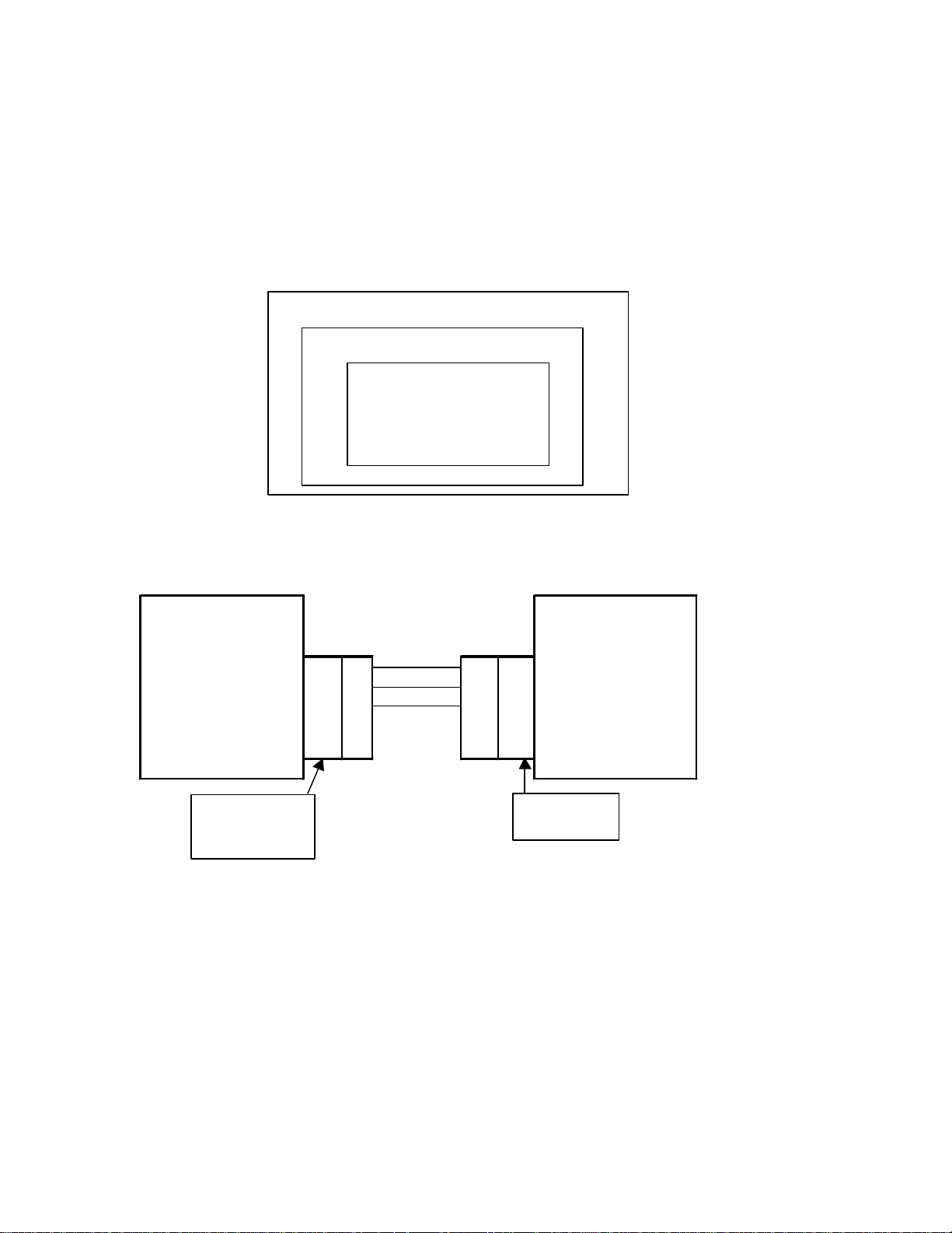
4 General Description
The intention of the SDP-3 serial port and protocol communication is for an external connected HOST to
control and obtain status from the SDP-3. The protocol has been designed to focus on two specific goals.
The first, is HOST uploading and downloading of SDP-3 configuration, and system/effect setups. The
second, is HOST control of basic user adjustable parameters. (i.e. input, volume, balance…)
HOST
Rs-232 Serial Link
CD VOL
4 of 4
Page 5
SerialDef,SDP-3.doc printed on 1/17/02
The SDP-3 uses simple notification, command, response and acknowledgment packets to have
communication transactions with a given HOST. This protocol is designed for point to point
communication between a HOST and SDP-3. The SDP-3 Protocol is a 3 layered system. The SDP-3 serial
protocol allows for the SDP-3 or the HOST to initiate a communication transaction. The HOST initiates
most transactions. SDP-3 then responds to the HOST command with either a response or acknowledgment
packet. There are a few asynchronous notifications that SDP-3 initiates indicating system changes. Each
transaction initiated must wait for a corresponding response before initiating the next transmission.
The 3 protocol layers are: Physical, Data Link, and Application Layers.
Physical Layer (RS232)
Data Link Layer
Application Layer
5 Physical Layer
5.1 DB-9 RS232 Connector
SDP-3 Typical Host
Ch A Transmit Data 2 2 Rx Data
Ch A Receive Data 3 3 Tx Data
Ch A Ground 5 5 Ground
9 Pin D-Shell
(female) lower
connector
Note: The wiring requirements for a 9 pin to 9 pin serial connection, are a male to female straight through
cable.
9-Pin D-Shell
(male)
5.2 Serial Port Driver
SDP-3 serial port has been setup to operate as follows:
Operating Mode: Full Duplex
Baud rate: 19.2K baud
Data Size: 8 bits
Parity: Odd
Stop Bits: 1
5 of 5
Page 6

SerialDef,SDP-3.doc printed on 1/17/02
Last Byte
End of Packet (EOP)
0xF2
5.3 Errors
The SDP-3 will detect parity, framing and data overrun errors. If an error is detected by the SDP-3, the SDP-3
will transmit an NAK packet with a error code of: DC_ERR_PARTIY, DC_ERR_FRAME, DC_ERR_OVER,
corresponding to the error detected. If any of the physical layer errors are detected, the complete packet is
corrupted and the SDP-3 will reset the transaction and begin to look for a start of packet byte.
All Error codes are listed in Appendix B Error Codes.
5.4 SDP-3 Receive Buffer
The SDP-3 has an internal receive buffer. The buffer is 256 Bytes and will transmit a NAK packet with an
error code of DC_ERR_BUFFER_FULL to the HOST with if the buffer is full. If the buffer is full, all data
transmitted to the SDP-3 will be ignored. Therefore, making the currently transmitted packet, if partial
transmitted invalid.
6 Data Link Layer
The data link layer is used to define a transmission packet. The layer appends a header and tail that
encloses the transmitted application packet data. The data link header will contain the start of packet byte
and count of bytes to follow. The data link tail will contain the end of packet byte.
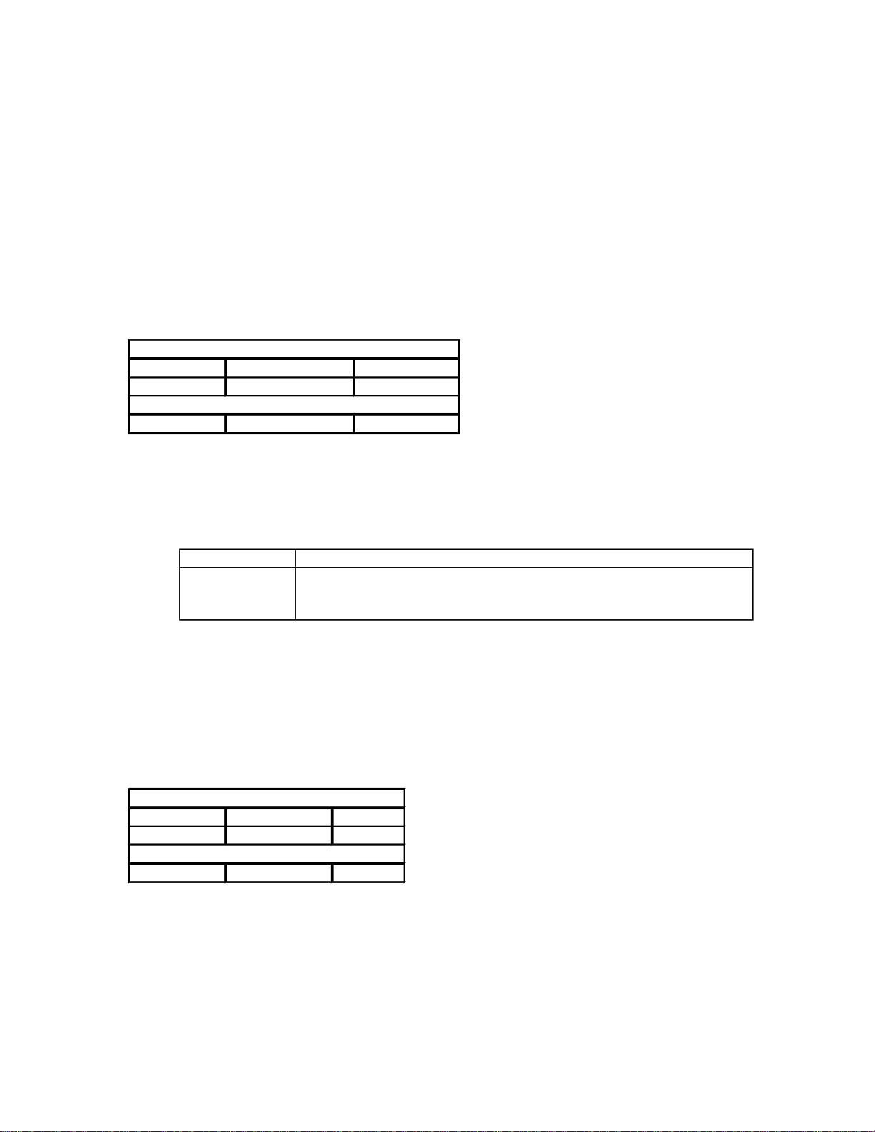
Data Link Header:
Byte Number Description Value
First Byte(0) Start of Packet(SOP) 0xF1
Byte(1) DLL Data Count nn
Application Header:
Byte(2) Command nn
Byte(3) APP Data Count(number of application data bytes to Follow) nn
Application Data:
Byte(4) Data[0] nn
Byte(5) Data[1] nn
… Data[…] nn
Last Data Byte -1 Data[Data Count -1] nn
Data Link Tail:
6.1 Errors
If the number of DLL data bytes received is the same as the data count and a EOP has not been received, the
SDP-3 responds by transmitting a NAK packet with an error code DC_ERR_INVALID_PACKET, and then
continues to look for a SOP byte and will not process the application packet. The HOST can use this as an
indicator to retransmit the corrupted packet.
7 Application Layer
7.1 SDP-3 Asynchronous Notification Packets
SDP-3 has been designed to transmit the asynchronous notification packets follow ing these system
changes:
6 of 6
Page 7
SerialDef,SDP-3.doc printed on 1/17/02
N/A
N/A
1. Power On
2. Entering Standby
3. Front Panel Display update.
The notification packets are defined as follows:
7.1.1 Wakeup Notification
By transmitting the Wakeup Notification, SDP-3 indicates the unit has just “powered on” or reset and is
ready to receive host commands. If no acknowledgment is received within ACK_TIMEOUT, SDP-3 will
continue to operate. This notification is primarily for the HOST to know the status of the SDP-3.
7.1.1.1 Notification Packet Description
Application Header:
Command DC_WAKEUP 0x01
Data Count 0 0x00
Application Data:
7.1.1.2 Host Response Expected
Following the transmission of the Wakeup notification SDP-3 will wait for an ACK.
7.1.1.2.1 Actions to Response Codes
ACK SDP-3 continues to operate.
NAK Error Code SDP-3 will retransmit the Wakeup Notification until it receives an ACK or it
reaches the RETRANSMIT_COUNT. If the RETRANSMIT_COUNT is
exceeded then SDP-3 continues to operate.
7.1.2 Sleep Notification
By transmitting the Sleep Notification, SDP-3 indicates the unit is shutting down into a standby mode.
Because the hard power switch could be activated independently of the SDP-3 system software, hard power
down will not be notified. Acknowledgment of the Sleep Notification is not required. This notification is
primarily for the HOST to know the operating status of the SDP-3.
7.1.2.1 Notification Packet Description
Application Header:
Command DC_SLEEP 0x02
Data Count 0 0x00
Application Data:
7.1.3 Front Panel Display Buffer
SDP-3 will transmit the front panel display buffer following the update to the SDP-3 front panel display. The
SDP-3 front panel display is 2 X 20 ASCII character display. The HOST can control the operation of this
notification message by FPD internal control registers. Individual notifications can be enabled or disabled
and the minimum transmit interval can be adjusted. Transmission of the display buffer is asynchronous to
other host/SDP-3 communication and will only transmit following the completion of any communication
7 of 7
Page 8
SerialDef,SDP-3.doc printed on 1/17/02
Data[22] - Data[42]
Line2
ch ch ch … 0x00
Data[1]
Value
nn
exchanges in progress or pending. The FPD control register command packets are described in section
7.3.14 Get FPD Control Registers.
7.1.3.1 Notifica tion Packet Description
Application Header:
Command DC_FPD 0x03
Data Count 42 0x2A
Application Data:
Data[0] - Data[21] Line1 ch ch ch… 0x00
7.1.3.2 Data Description
Line1
Data Type: Null (0x00) terminated ASCII character string.
Max Length: DISP_LINE_LENGTH defined in Appendix E Protocol Constants.
Line2
Data Type: Null(0x00) terminated ASCII character string.
Max Length: DISP_LINE_LENGTH defined in Appendix E Protocol Constants.
The SDP-3 includes 8 custom characters that are defined to display increments of a display block. (i.e.
Volume Bar) The custom characters are ASCII character codes 08 - 0F(hex). The codes are used as follows:
'08' - left 1 bar
'09' - left 2 bars
'0A' - left 3 bars
'0B' - left 4 bars
'0C' - Full Cell
'0D' - Underscore
'0E' - right 3 bars
'0F' - not in use
7.1.3.3 HOST Response
The SDP-3 does not look for any response from the HOST.
7.1.4 Parameter Change Notification
SDP-3 will transmit predetermined parameter change notifications. If a parameter value is changed due to
any user action or system action the SDP-3 will transmit the current value of the parameter that is changing.
7.1.4.1 Notification Packet Description
Application Header:
Command DC_PARAM_CHG_MSG 0x04
Data Count 2 0x00
Application Data:
Data[0] ParamId nn
7.1.4.2 Data Description
ParamId:
Data Type: Unsigned 8 bit integer
8 of 8
Page 9

SerialDef,SDP-3.doc printed on 1/17/02
Data[0]
Command
nn
Max: Set by the System Parameter Count in the “Unit Configuration Packet”.
Value: The Current V alue for this system parameter.
Data Type: Unsigned 8 bit integer
Max: Set by the Max Value per the System Parameter Definition response
Packet for the Parameter Id of this packet.
7.1.4.3 HOST Response
The SDP-3 does not look for any response from the HOST.
7.1.4.4 Supported System Parameters
The following parameters will be supported by this Parameter Change Notification:
Parameter SDP-3 Parameter Name
Current Effect PROGRAM
Mute MUTE
System Volume VOLUME
Balance LR_BALANCE
Input Selection INPUT
Record/Zone 2 On/Off RECORD_ENABLED
Zone 2 Volume Z2_VOL
Zone 2 Balance Z2_BAL
Zone 2 Mute Z2_MUTE
Bass BASS
Treble TREBLE
Loudness LOUDNESS
Tilt TILT
Menu Background On/Off MENU_BKGND
The parameter definitions for each of these parameters can be obtained by querying the SDP-3 with the
DC_CMD_GET_SYS_PARAM_BY_NAME command. The DC_RESP_SYS_PARAM_DEF will contain the
ParamId for each of the parameters. The ParamId may change with s/w version changes, but the Parameter
Name will not.
7.2 Acknowledgment Packets
Acknowledge and No Acknowledge packets are used to communicate transmission, packet and data
validation status. Both the HOST and SDP-3 can transmit and receive these packets.
7.2.1 Acknowledge
7.2.1.1 Packet Description
Application Header:
Command DC_ACK 0xE0
Data Count 1 0x01
Application Data:
7.2.1.2 Data Description
Command:
Data Type: Valid SDP-3 command as defined in Appendix A Command Codes.
9 of 9
Page 10
SerialDef,SDP-3.doc printed on 1/17/02
Data[1]
ErrorCode
nn
N/A
N/A
7.2.2 No Acknowledge
7.2.2.1 Packet Description
Application Header:
Command DC_NACK 0xE1
Data Count 2 0x02
Application Data:
Data[0] Command nn
7.2.2.2 Data Description
Command:
Data Type: Valid SDP-3 command as defined in Appendix A Command Codes.
Error Code:
Data Type: Error code as defined in Appendix B Error Codes.
7.3 Host Initiated Command Packets
The SDP-3 serial communication protocol has been designed to respond to the following commands as
described below. Each command is tr ansmitted to the SDP-3 with the identified parameters. If the command
is successfully received and processed by the SDP-3, the unit will respond with the described response
packet or action.
7.3.1 Reset Unit
Commands the SDP-3 to soft reset.
7.3.1.1 Command Packet Description
Application Header:
Command DC_CMD_RESET 0x10
Data Count 0 0x00
Application Data:
7.3.1.2 SDP-3 Response
The SDP-3 will perform and internal reset. After reset the SDP-3 will go through a soft power -up
initialization. This includes transmitting the “Wakeup Notification Packet”. A soft reset does not reinitialize
the SDP-3. Nonvolatile RAM is maintained.
7.3.2 Restore Defaults
Commands SDP-3 restore the system and effect parameters to the factory defaults.
7.3.2.1 Command Packet Description
Application Header:
Command DC_CMD_RESTORE_DEFAULTS 0x13
Data Count 0 0x00
Application Data:
10 of 10
Page 11
SerialDef,SDP-3.doc printed on 1/17/02
Data[0]
KeyCode
nn
N/A
7.3.2.2 SDP-3 Response
The SDP-3 will reset, clear any saved system and effect parameters in Nonvolatile RAM, and restore the
factory default system and effect parameters. After reset the SDP-3 will go through a soft power -up
initialization. This includes transmitting the “Wakeup Notification Packet”.
7.3.3 Send IR Command
Transmits IR command key codes to the SDP-3.
7.3.3.1 Command Packet Description
Application Header:
Command DC_CMD_IR 0x14
Data Count 1 0x01
Application Data:
7.3.3.2 Data Description
Key Code:
Data Type: Unsigned 8 bit integer.
Valid Values: Appendix C SDP-3 IR-Codes
7.3.3.3 SDP-3 Response
The Key Code is processed as a valid IR code. No acknowledgment will be sent from SDP-3.
7.3.3.4 Data Validation
The Key Code data will be verified as a legal IR code. If the Code is not valid the SDP-3 will not respond.
7.3.4 Get SDP-3 Unit Configuration
Request to SDP-3 for it’s current unit configuration. SDP-3 will respond with “Unit Configuration Packet”.
The HOST should use this information to determine if any information saved by the HOST is current.
7.3.4.1 Command Packet Description
Application Header:
Command DC_CMD_GET_CONFIG 0x15
Data Count 0 0x00
Application Data:
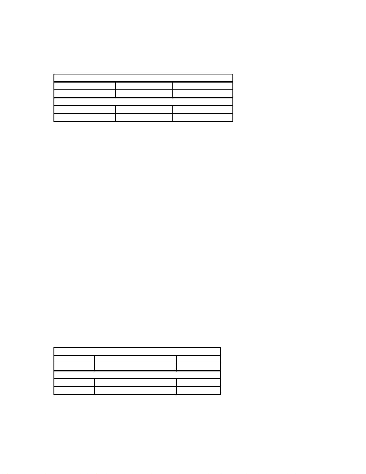
7.3.4.2 SDP-3 Unit Configuration Response Packet
11 of 11
Page 12
SerialDef,SDP-3.doc printed on 1/17/02
Data[24]
TimeStamp[15]
0x00
Application Header:
Command DC_RESP_UNIT_CONFIG 0x80
Data Count 25 0x19
Application Data:
Data[0] ProductId nn
Data[1] Software Type nn
Data[2] Software Level nn
Data[3] Software Major Revision nn
Data[4] Software Minor Revision nn
Data[5] Protocol Major Revision nn
Data[6] Protocol Minor Revision nn
Data[7] Total Number of System Parameters nn
Data[8] Total Number of Effects nn
Data[9] TimeStamp[0] ch
Data[10] TimeStamp[1] ch
Data[11] TimeStamp[2] ch
Data[12] TimeStamp[3] ch
Data[13] TimeStamp[4] ch
Data[14] TimeStamp[5] ch
Data[15] TimeStamp[6] ch
Data[16] TimeStamp[7] ch
Data[17] TimeStamp[8] ch
Data[18] TimeStamp[9] ch
Data[19] TimeStamp[10] ch
Data[20] TimeStamp[11] ch
Data[21] TimeStamp[12] ch
Data[22] TimeStamp[13] ch
Data[23] TimeStamp[14] ch
7.3.4.3 Data Description
Product Id: This unsigned 8 bit value describes the product.
Product ID
Lexicon Dc-2 1
Lexicon MC-1 2
JBL Synthesis SDP-3 3
Software Type: An unsigned 8 bit value indicating the current configuration of the unit’s
software. The following table shows the values assigned to the available types:
SW Type
THX 1
AC3 2
DTS 3
12 of 12
Page 13

SerialDef,SDP-3.doc printed on 1/17/02
UNSUPPORTED
5
Software Level: The following table shows the values assigned to the possible software levels:
SW Level
RELEASED 0
PRE_ALPHA 1
ALPHA 2
BETA 3
GAMMA 4
*Note: SW level indicates the status of the SDP-3 internal application software.
Software Major Revision: An unsigned integer value indicating the unit’s major software version. The
host should use this information to determine if new effects, effect parameters, or
system parameters have been added or removed.
Software Minor Revision: An unsigned integer value indicating this unit’s minor software version.
Indicates the units software operation has changed but effects, effect
parameters, or system parameters have not changed.
Protocol Major Revision: An unsigned integer value indicating the serial communication protocol major
version. The host should use this value to determine if new commands,
notifications, or response packets have been added or deleted from this
specification.
Protocol Minor Revision: An unsigned integer value indicating the serial communication protocol minor
version. The host should use this value to determine if the existing commands,
notifications, or response packets have changed in this specification
Total Number of System
Parameters: An unsigned integer value indicating the maximum number of system parameters
for this version of software. This should be used to determine the data count for
the “SDP-3 System Parameter Values Packet” and “Set System Parameter Values
Packet”.
Total Number of Effects: An unsigned integer value indicating the maximum number of effects available
for this version of software. This should be used to determine the maximum
Effect Id used in the “Get Effect Definition Packet”, “Get Effect Parameter
Definition Packet”, “Set Effect Name Packet”, and “Set Effect Parameter Values
Packet”.
Time Stamp: Is a null terminated ASCII text string describing the build date and time of the
current ROM. The Format of this text string is:
“yy/mm/dd/(sp)/hh:mm”
yy - is the last two digits of the year (i.e. year 1999 = 99, year 2000 = 00)
mm - is the month
dd - is the day
(sp) - is an ASCII space character (0x20)
hh - is the hour
mm - is the minute
7.3.5 Get System Status
Request to SDP-3 for it’s current system status. SDP-3 will respond with “System Status Packet”.
7.3.5.1 Command Packet Description
13 of 13
Page 14

SerialDef,SDP-3.doc printed on 1/17/02
N/A
RATE_96
4
Application Header:
Command DC_CMD_GET_SYS_STATUS 0x16
Data Count 0 0x00
Application Data:
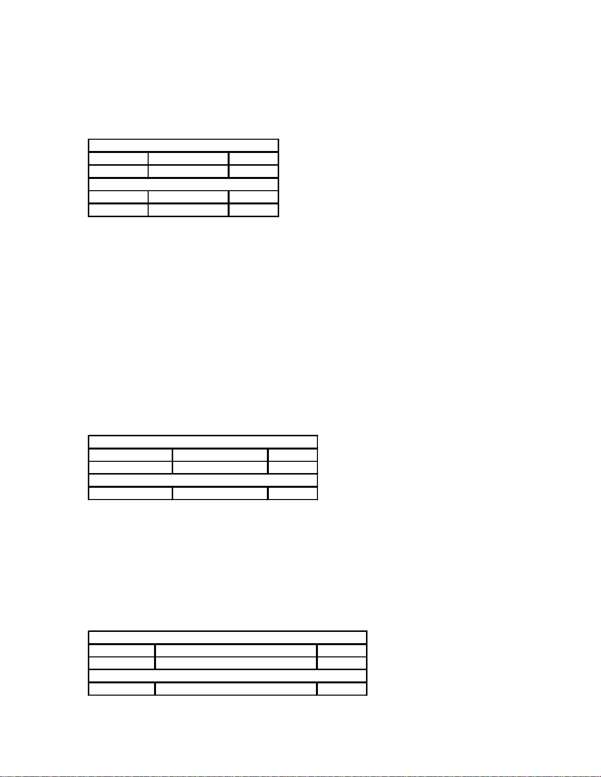
7.3.5.2 System Status Response Packet
Application Header:
Command DC_RESP_SYS_STATUS 0x81
Data Count 10 0x0A
Application Data:
Data[0] System Volume nn
Data[1] Current Input nn
Data[2] Current EffectId nn
Data[3] Current Input Sample Rate nn
Data[4] Current Input Format nn
Data[5] Mute Active nn
Data[6] Effect Bypass Active nn
Data[7] Left/Right Balance nn
Data[8] Front/Back Balance nn
Data[9] Video Synch nn
7.3.5.3 Data Description
System Volume:
Data Type: Unsigned 8 bit integer.
Maximum Value: 86
Conversion: 0 = -80 dB
86 = +06 dB
Current Input:
Data Type: Unsigned 8 bit integer.
Definition: Appendix D Input Id’s
Current Effect Id:
Data Type: Unsigned 8 bit integer.
Maximum Value: Set by “Total Number of Effects” in the “Unit Configuration”
Packet.
Current Input Sample Rate
Data Type: Unsigned 8 bit integer.
SAMPLE RATE
RATE_UNKNOWN 0
RATE_44 1
RATE_48 2
RATE_88 3
Current Input Format:
Data Type: Unsigned 8 bit integer.
14 of 14
Page 15

SerialDef,SDP-3.doc printed on 1/17/02
INSTREAM_AC3_51
6
N/A
DATA STREAM TYPE
INSTREAM_UNKNOWN 0
INSTREAM_AC3 1
INSTREAM_PCM 2
INSTREAM_ANALOG 3
INSTREAM_DTS 4
INSTREAM_AC3_20 5
Mute Active:
Data Type: Boolean.
TRUE: System Mute is Active
FALSE: System is unmuted.
Effect Bypass Active:
Data Type: Boolean.
TRUE: Effect Bypass is Active
FALSE: Effect Bypass is not Active.
Left/Right Balance:
Data Type: Unsigned 8 bit integer.
Maximum Value: 32
Conversion: 0 = Left
32 = Right
Front/Back Balance:
Data Type: Unsigned 8 bit integer.
Maximum Value: 32
Conversion: 0 = Front
32 = Back
Video Synch:
Data Type: Boolean.
TRUE: SDP-3 has detected Video Synch for current video input
FALSE: SDP-3 can not detect Video Synch for the current video input
7.3.6 Get Record/Zone 2 Status
Request to SDP-3 for it’s Record/Zone2 Status. SDP-3 will respond with “record/Zone2 Status Packet”.
7.3.6.1 Command Packet Description
Application Header:
Command DC_CMD_GET_REC_STATUS 0x17
Data Count 0 0x00
Application Data:
7.3.6.2 Record/Zone2 Status Response Packet
15 of 15
Page 16

SerialDef,SDP-3.doc printed on 1/17/02
Data[4]
Zone2 Balance
nn
Application Header:
Command DC_RESP_REC_ZONE2_STATUS 0x82
Data Count 5 0x05
Application Data:
Data[0] Zone2 Volume nn
Data[1] Assigned Input nn
Data[2] Zone2 Mute Active nn
Data[3] Record Active nn
7.3.6.3 Data Description
Zone2 Volume:
Data Type: Unsigned 8 bit integer.
Maximum Value: 86
Conversion: 0 = -80 dB
86 = +06 dB
Assigned Input:
Indicates the input that is currently assigned for the record/zone2 outputs.
Data Type: Unsigned 8 bit integer.
Definition: Appendix D Input Id’s
Zone2 Active:
Data Type: Boolean.
TRUE: Zone2 Outputs are active.
FALSE: Zone2 Outputs are not active.
Record Active:
Data Type: Boolean.
TRUE: Digital Record Output is active
FALSE: Digital Record Output is not Active.
Zone 2 Balance:
Data Type: Unsigned 8 bit integer.
Maximum Value: 32
Conversion: 0 = Left
32 = Right
7.3.7 Get System Parameter Definition
There are two ways to request a SDP-3 system parameter definition. The first is by Parameter Id and the
second by parameter name. SDP-3 will respond with “System Parameter Definition Packet”.
7.3.7.1 Get System Parameter Definition by Id Command Packet
Error! Not a valid link.
7.3.7.2 Data Description
Param Id:
Data Type: Unsigned 8 bit integer
Max: Set by the System Parameter Count in the “Unit Configuration Packet”.
7.3.7.3 Data Validation:
The Param Id must be a valid parameter number. If it is not the SDP-3 will respond with a NAK packet and
error code DC_ERR_ INVALID_PARAM_NUMBER.
16 of 16
Page 17

SerialDef,SDP-3.doc printed on 1/17/02
Data[0]-Data[DataCount-1]
ParamName
ch ch ch … 0x00
Data[3]- Data[DataCount-1]
ParamName
ch ch ch … 0x00
7.3.7.4 Get System Parameter Definition by Name Command Packet
Application Header:
Command DC_CMD_GET_SYS_PARAM_BY_NAME 0x19
Data Count strlen(ParamName) + 1 nn
Application Data:
7.3.7.5 Data Description
Param Name:
Data Type: Null(0x00) terminated ASCII character string.
Max Length: PARAM_NAME_LENGTH defined in Appendix E Protocol Constants.
7.3.7.6 Data Validation:
The Param Name must be a valid Parameter name. If it is not the SDP-3 will respond with a NAK packet and
error code DC_ERR_ INVALID_PARAM_NAME.
7.3.7.7 System Parameter Definition Response Packet
This packet describes the defining information for a given system parameter.
Application Header:
Command DC_RESP_SYS_PARAM_DEF 0x83
Data Count 3 + strlen(ParamName) + 1 nn
Application Data:
Data[0] ParamId nn
Data[1] MaxValue nn
Data[2] Value nn
7.3.7.8 Data Description
Param Id: The Integer Id assigned to this system parameter.
Data Type: Unsigned 8 bit integer
Max: Set by the System Parameter Count in the “Unit Configuration Packet”
Max Value: Maximum Value allowed for this system parameter.
Data Type: Unsigned 8 bit integer
Max: 255
Value: The Current Value for this system parameter.
Data Type: Unsigned 8 bit integer
Max: Max Value (in this Packet)
Param Name:
Data Type: Null (0x00) terminated ASCII character string.
Max Length: PARAM_NAME_LENGTH defined in Appendix E Protocol Constants.
7.3.8 Get System Parameter Values
Request to SDP-3 for all current system parameter values. SDP-3 will respond with the “System Parameter
Values Packet”.
17 of 17
Page 18

SerialDef,SDP-3.doc printed on 1/17/02
N/A
Data[SYS_PARAM_COUNT-1]
sys_param_value[SYS_PARAM_COUNT-1]
nn
Data[0]
EffectId
nn
7.3.8.1 Command Packet Description
Application Header:
Command DC_CMD_GET_SYS_PARAM_VALUES 0x1A
Data Count 0 0x00
Application Data:
7.3.8.2 System Parameter Values Response Packet
Application Header:
Command DC_RESP_SYS_PARAM_VALUES 0x84
Data Count SYS_PARAM_COUNT nn
Application Data:
Data[0] sys_param_value[0] nn
Data[1] sys_param_value[1] nn
Data[…] sys_param_value[…] nn
7.3.8.3 Data Description
sys_param_value:
Data Type: Unsigned 8 bit integer Array.
Max: Dependent on the parameter definition.
7.3.9 Get Effect Definition by Id
Request to SDP-3 for an effect definition. SDP-3 will respond with “Effect Definition Packet”.
7.3.9.1 Command Packet Description
Application Header:
Command DC_CMD_GET_EFFECT 0x1B
Data Count 1 0x01
Application Data:
7.3.9.2 Data Description
Effect Id:
Data Type: Unsigned 8 bit integer
Max: Set by the Effect Count in the “Unit Configuration Packet”.
7.3.9.3 Data Validation:
The Effect Id must be a valid Effect Id. If it is not the SDP-3 will respond with a NAK packet and error code
DC_ERR_ INVALID_EFFECT_ID.
7.3.9.4 Effect Definition Response Packet
18 of 18
Page 19

SerialDef,SDP-3.doc printed on 1/17/02
Data[2]- Data[DataCount-1]
EffectName
ch ch ch … 0x00
Data[1]
ParamId
nn
Application Header:
Command DC_RESP_EFFECT_DEF 0x85
Data Count 2 + strlen(EffectName) + 1 nn
Application Data:
Data[0] EffectId nn
Data[1] MaxParameters nn
7.3.9.5 Data Description
Effect Id:
Data Type: Unsigned 8 bit integer
Max: Set by the Effect Count in the “Unit Configuration Packet”.
Max Parameters: Maximum number of parameters assigned to this effect.
Effect Name:
Data Type: Null (0x00) terminated ASCII character string.
Max Length: EFFECT_NAME_LENGTH defined in Appendix E Protocol Constants.
7.3.10 Get Effect Parameter Definition
Request to SDP-3 for an effect parameter definition. SDP-3 will respond with “Effect Parameter Definition
Packet”.
7.3.10.1 Command Packet Description
Application Header:
Command DC_CMD_GET_EFFECT_PARAM_DEF 0x1C
Data Count 2 0x02
Application Data:
Data[0] EffectId nn
7.3.10.2 Data Description
Effect Id:
Data Type: Unsigned 8 bit integer.
Max: Set by the Effect Count in the “Unit Configuration Packet”.
Param Id:
Data Type: Unsigned 8 bit integer.
Max: Set by the Parameter Count in the “Effect Def inition Packet”.
7.3.10.3 Data Validation:
The Effect Id must be a valid Effect Id. If it is not the SDP-3 will respond with a NAK packet and error code
DC_ERR_ INVALID_EFFECT_ID. The Param Id must be a valid Parameter number. If it is not the SDP-3 will
respond with a NAK packet and error code DC_ERR_ INVALID_PARAM_NUMBER.
7.3.10.4 Effect Parameter Definition Response Packet
19 of 19
Page 20

SerialDef,SDP-3.doc printed on 1/17/02
Data[2]
Value
nn
Data[0]
EffectId
nn
Data[DataCount-1]
effect_param_value[EffectParamCount-1]
nn
Application Header:
Command DC_RESP_EFFECT_PARAM_DEF 0x86
Data Count 3 0x03
Application Data:
Data[0] EffectId nn
Data[1] MaxValue nn
7.3.10.5 Data Description
Effect Id:
Data Type: Unsigned 8 bit integer.
Max: Set by the Effect Count in the “Unit Configuration Packet”.
Max Value: Maximum Value allowed for this parameter.
Data Type: Unsigned 8 bit integer
Max: 255
Value: The Current Value for this parameter.
Data Type: Unsigned 8 bit integer
Max: Max Value(in this Packet)
7.3.11 Get Effect Parameter Values
Request to SDP-3 for an effect’s parameter values. SDP-3 will respond with “Effect Parameter Values
Packet”.
7.3.11.1 Command Packet Description
Application Header:
Command DC_CMD_GET_EFFECT_PARAM_VALUES 0x1D
Data Count 1 0x01
Application Data:
7.3.11.2 Data Description
Effect Id:
Data Type: Unsigned 8 bit integer.
Max: Set by the Effect Count in the “Unit Configuration Packet”.
7.3.11.3 Data Validation:
The Effect Id must be a valid Effect Id. If it is not the SDP-3 will respond with a NAK packet and error code
DC_ERR_ INVALID_EFFECT_ID.
7.3.11.4 Effect Parameter Values Response Packet
Application Header:
Command DC_RESP_EFFECT_PARAM_VALUES 0x87
Data Count 1 + EffectParamCount nn
Application Data:
Data[0] EffectId nn
Data[1] effect_param_value[0] nn
Data[…] effect_param_value[…] nn
20 of 20
Page 21
SerialDef,SDP-3.doc printed on 1/17/02
N/A
Data[0]- Data[DataCount-1]
CustomName
ch ch ch … 0x00
Data[0]
InputId
nn
7.3.11.5 Data Description
Effect Id:
Data Type: Unsigned 8 bit integer.
Max: Set by the Effect Count in the “Unit Configuration Packet”.
effect_param_value:
Data Type: Unsigned 8 bit integer array.
Max: Dependent on the parameter definition
7.3.12 Get Custom Name
Request to SDP-3 for an effect definition. SDP-3 will respond with “Custom Name Packet”.
7.3.12.1 Command Packet Description
Application Header:
Command DC_CMD_GET_CUST_NAME 0x2B
Data Count 0 0x00
Application Data:
7.3.12.2 Data Description
N/A
7.3.12.3 Custom Name Response Packet
Application Header:
Command DC_RESP_CUST_NAME 0x89
Data Count strlen(CustomName) + 1 nn
Application Data:
7.3.12.4 Data Description
Custom Name:
Data Type: Null (0x00) terminated ASCII character string.
Max Length: CUSTOM_NAME_LENGTH defined in Appendix E Protocol Constants.
7.3.13 Get Input Name by Id
Request to SDP-3 for an input name. SDP-3 will respond with “Input Name Packet”.
7.3.13.1 Command Packet Description
Application Header:
Command DC_CMD_GET_INPUT_NAME 0x2D
Data Count 1 0x01
Application Data:
7.3.13.2 Data Description
Input Id:
Data Type: Unsigned 8 bit Integer
Max Value: 7
21 of 21
Page 22

SerialDef,SDP-3.doc printed on 1/17/02
Data[2]- Data[DataCount-1]
InputName
ch ch ch … 0x00
N/A
Conversion: Input Id are defined in Appendix D Input Id’s
7.3.13.3 Data Validation:
The Input Id must be a valid Input number. If it is not the SDP-3 will respond with a NAK packet and error
code DC_ERR_ INVALID_INPUT_ID.
7.3.13.4 Input Name Response Packet
Application Header:
Command DC_RESP_INPUT_NAME 0x8A
Data Count strlen(InputName) + 2 nn
Application Data:
Data[0] InputId nn
7.3.13.5 Data Description
Input Id:
Data Type: Unsigned 8 bit Integer
Max Value: 7
Conversion: Input Id are defined in Appendix D Input Id’s
Input Name:
Data Type: Null(0x00) terminated ASCII character string.
Max Length: INPUT_NAME_LENGTH defined in Appendix E Protocol Constants.
7.3.14 Get FPD Control Registers
Request to SDP-3 for FPD control registers. SDP-3 will respond with “FPD Control Register Packet”.
7.3.14.1 Command Packet Description
Application Header:
Command DC_CMD_GET_FPD_CONTROL 0x29
Data Count 0 0x00
Application Data:
7.3.14.2 FPD Control Register Response Packet
Application Header:
Command DC_RESP_FPD_CONTROL 0x88
Data Count 4 0X04
Application Data:
Data[0] FPD_CtrlReg0 nn
Data[1] FPD_CtrlReg1 nn
Data[2] FPD_CtrlReg2 nn
Data[4] FPD_MinUpdate nn
7.3.14.3 Data Description
FPD_CtrlReg0: Bit Pack as defined in Appendix F FPD Control Registers
22 of 22
Page 23

SerialDef,SDP-3.doc printed on 1/17/02
Data[SYS_PARAM_COUNT-1]
sys_param_value[SYS_PARAM_COUNT-1]
nn
Data[DataCount-1]
effect_param_value[EFFECT_COUNT-1]
nn
FPD_CtrlReg1: Bit Pack as defined in Appendix F FPD Control Registers
FPD_CtrlReg2: Bit Pack as defined in Appendix F FPD Control Registers
FPD_MinUpdate: This value sets the minimum time between FPD Notification Transmissions.
Data Type: Unsigned 8 bit integer
Default: 50(100 mSec)
Range: 50 - 255 counts
Conversion: 500 counts/sec
7.3.15 Set System Parameter Values
Command SDP-3 to replace the system parameter values with the values in this packet.
7.3.15.1 Command Packet Description
Application Header:
Command DC_CMD_SET_SYS_PARAM_VALUES 0x1E
Data Count SYS_PARAM_COUNT nn
Application Data:
Data[0] sys_param_value[0] nn
Data[1] sys_param_value[1] nn
Data[…] sys_param_value[…] nn
7.3.15.2 Data Description
sys_param_values:
Data Type: Array of unsigned 8 bit Integers
Max Each value is set by its system parameter definition.
Array Size: Set by the System Parameter Count in the “Unit Configuration Packet”.
7.3.15.3 SDP-3 Response
The SDP-3 will assign the values from the packet to the system parameter values in Nonvolatile RAM, and
reset the unit to initialize the new values.
7.3.15.4 Data Validation
If any of the values exceeds it’s maximum value the SDP-3 will ignore the command and transmit a DC_NAK
command with an error code DC_INVALID_DATA.
7.3.16 Set Effect Parameter Values
Commands SDP-3 to replace the given effect parameter values with the values in this packet.
7.3.16.1 Command Packet Description
Application Header:
Command DC_CMD_SET_EFFECT_PARAM_VALUES 0x1F
Data Count EFFECT_COUNT[EffectId] + 1 nn
Application Data:
Data[0] EffectId nn
Data[1] effect_param_value[0] nn
Data[…] effect_param_value[…] nn
23 of 23
Page 24

SerialDef,SDP-3.doc printed on 1/17/02
Data[1]-Data[DataCount-1]
EffectName
ch ch ch … 0x00
7.3.16.2 Data Description
Effect Id:
Data Type: Unsigned 8 bit integer.
Max: Set by the Effect Count in the “Unit Configuration Packet”.
effect_param_value:
Data Type: Unsigned 8 bit integer array.
Max: Dependent on the parameter definition
7.3.16.3 SDP-3 Response
The SDP-3 will assign the values from the packet to the effect parameter values in Nonvolatile RAM. If the
effect is active the SDP-3 will reload the effect to activate all the parameter values.
7.3.16.4 Data Validation
If a value is passed that exceeds the maximum value of that parameter the SDP-3 will ignore the command
and transmit a DC_NAK command with an error code DC_ERR_INVALID_DATA.
7.3.17 Set Effect Name by Effect Id
Sets an effect name to the transmitted value for a given effect.
7.3.17.1 Command Packet Description
Application Header:
Command DC_CMD_SET_EFFECT_NAME 0x20
Data Count strlen(EffectName) + 2 nn
Application Data:
Data[0] EffectId nn
7.3.17.2 Data Description
Effect Id:
Data Type: Unsigned 8 bit integer
Max: Set by the Effect Count in the “Unit Configuration Packet”.
Effect Name:
Data Type: Null (0x00) terminated ASCII character string.
Max Length: EFFECT_NAME_LENGTH defined in Appendix E Protocol Constants.
7.3.17.3 SDP-3 Response
The SDP-3 will copy the Effect Name to Nonvolatile RAM. If the effect being adjusted is active the effect
will be reloaded for the changes to be initialized.
7.3.17.4 Data Validation:
The Effect Id must be a valid Effect Id. If it is not the SDP-3 will respond with a NAK packet and error code
DC_ERR_ INVALID_EFFECT_ID. If an invalid string is passed, SDP-3 will ignore the command and
transmit a DC_NAK command with an error code DC_ERR _INVALID_DATA.
7.3.18 Set System Volume
Commands SDP-3 to set the system volume with the value in this packet.
7.3.18.1 Command Packet Description
24 of 24
Page 25

SerialDef,SDP-3.doc printed on 1/17/02
Data[0]
Value
nn
Data[0]
Value
nn
Application Header:
Command DC_CMD_SET_SYS_VOLUME 0x21
Data Count 1 0x01
Application Data:
7.3.18.2 Data Description
Value:
Data Type: Unsigned 8 bit integer.
Max: 86
Conversion: 0 = -80 dB
86 = +06 dB
7.3.18.3 SDP-3 Response
The SDP-3 will assign the value from the packet to the system volume.
7.3.18.4 Data Validation
If a value is passed that exceeds the maximum value of that parameter the SDP-3 will ignore the command
and transmit a DC_NAK command with an error code DC_ERR_INVALID_DATA.
7.3.19 Set Main Balance
Commands SDP-3 to set the system balance to the value in this packet.
7.3.19.1 Command Packet Description
Application Header:
Command DC_CMD_SET_SYS_BALANCE 0x22
Data Count 1 0x01
Application Data:
7.3.19.2 Data Description
Value:
Data Type: Unsigned 8 bit integer.
Maximum Value: 32
Conversion: 0 = Left
32 = Right
7.3.19.3 SDP-3 Response
The SDP-3 will assign the value from the packet to the system balance.
7.3.19.4 Data Validation
If a value is passed that exceeds the maximum value of that parameter the SDP-3 will ignore the command
and transmit a DC_NAK command with an error code DC_INVALID_DATA.
7.3.20 Set Front/Back Balance
Commands SDP-3 to set the front/back balance to the value in this packet.
7.3.20.1 Packet Description
25 of 25
Page 26

SerialDef,SDP-3.doc printed on 1/17/02
Data[0]
Value
nn
Data[0]
EffectId
nn
Application Header:
Command DC_CMD_SET_FRONT_BACK_BALANCE 0x23
Data Count 1 0x01
Application Data:
7.3.20.2 Data Description
Value:
Data Type: Unsigned 8 bit integer.
Max: 32
Conversion: 0 = Front
32 = Back
7.3.20.3 SDP-3 Response
The SDP-3 will assign the value from the packet to the front/back balance.
7.3.20.4 Data Validation
If a value is passed that exceeds the maximum value of that parameter the SDP-3 will ignore the command
and transmit a NAK command with an error code DC_ERR_INVALID_DATA.
7.3.21 Set Active Effect by Id
Commands SDP-3 to set the active effect to the value in this packet.
7.3.21.1 Command Packet Description
Application Header:
Command DC_CMD_SET_EFFECT 0x24
Data Count 1 0x01
Application Data:
7.3.21.2 Data Description
Effect Id:
Data Type: Unsigned 8 bit integer
Max: Set by the Effect Count in the “Unit Configuration Packet”.
7.3.21.3 SDP-3 Response
The SDP-3 will load the desired effect.
7.3.21.4 Data Validation
If a value is passed that exceeds the maximum value of that parameter the SDP-3 will ignore the command
and transmit a NAK command with an error code DC_ERR_INVALID_DATA.
7.3.22 Set Record/Zone2 Input
Sets the Record/Zone 2 input. If Record/Zone2 was inactive, this command will set the input then activate
the Record/Zone 2 function.
7.3.22.1 Command Packet Description
26 of 26
Page 27

SerialDef,SDP-3.doc printed on 1/17/02
Data[0]
InputId
nn
Data[0]
InputId
nn
Application Header:
Command DC_CMD_SET_REC_INPUT 0x25
Data Count 1 0x01
Application Data:
7.3.22.2 Data Description
Input Id:
Data Type: Unsigned 8 bit Integer
Max Value: 7
Conversion: Input Id are defined in Appendix D Input Id’s
7.3.22.3 SDP-3 Response
7.3.22.4 Data Validation:
The Input Id must be a valid Input Id. If it is not the SDP-3 will respond with a NAK packet and error code
DC_ERR_ INVALID_INPUT_ID. If the input selection is disallowed (input blocked, digital input not
selected…) SDP-3 will respond with a NAK packet and error code DC_ERR_INVALID_INPUT If the input
is assigned the SDP-3 will respond with an ACK Packet.
7.3.23 Clear Record/Zone2 Input
Clears or Unassigns the Record/Zone 2 input. If Record/Zone2 is active, this command will unassign the
zone 2 input and set the record outputs to the main input source.
7.3.23.1 Packet Description
Application Header:
Command DC_CMD_CLEAR_REC_INPUT 0x26
Data Count 1 0x01
Application Data:
7.3.23.2 Data Description
Input Id:
Data Type: Unsigned 8 bit Integer
Max Value: 7
Conversion: Input Id are defined in Appendix D Input Id’s
7.3.23.3 SDP-3 Response
7.3.23.4 Data Validation
The Input Id must be a valid Input Id. If it is not the SDP-3 will respond with a NAK packet and error code
DC_ERR_ INVALID_INPUT_ID. If the input is unassigned the SDP-3 will respond with an ACK Packet. If
the record/zone 2 function was not active the SDP-3 will respond with an ACK packet.
7.3.24 Set Zone2 Volume
Commands SDP-3 to set the system volume with the value in this packet.
7.3.24.1 Command Packet Description
27 of 27
Page 28

SerialDef,SDP-3.doc printed on 1/17/02
Data[0]
Value
nn
Data[0]
Value
nn
Application Header:
Command DC_CMD_SET_ZONE2_VOLUME 0x27
Data Count 1 0x01
Application Data:
7.3.24.2 Data Description
Value:
Data Type: Unsigned 8 bit integer.
Max: 86
Conversion: 0 = -80 dB
86 = +06 dB
7.3.24.3 SDP-3 Response
The SDP-3 will assign the value from the packet to the zone2 volume.
7.3.24.4 Data Validation
If a value is passed that exceeds the maximum value of that parameter the SDP-3 will ignore the command
and transmit a NAK command with an error code DC_ERR_INVALID_DATA.
7.3.25 Set Zone2 Left/Right Balance
Commands SDP-3 to set the Zone2 balance to the value in this packet.
7.3.25.1 Packet Description
Application Header:
Command DC_CMD_SET_ZONE2_BALANCE 0x28
Data Count 1 0x01
Application Data:
7.3.25.2 Data Description
Value:
Data Type: Unsigned 8 bit integer.
Maximum Value: 32
Conversion: 0 = Left
32 = Right
7.3.25.3 SDP-3 Response
The SDP-3 will assign the value from the packet to the Zone2 balance.
7.3.25.4 Data Validation
If a value is passed that exceeds the maximum value of that param eter the SDP-3 will ignore the command
and transmit a NAK command with an error code DC_ERR_INVALID_DATA.
7.3.26 Set Custom Name
Sets the Custom Name that can be displayed when the unit powers up.
7.3.26.1 Packet Description
28 of 28
Page 29

SerialDef,SDP-3.doc printed on 1/17/02
Data[1]-Data[DataCount-1]
CustomName
ch ch ch … 0x00
Data[1]-Data[DataCount-1]
InputName
ch ch ch ... 0x00
Application Header:
Command DC_CMD_SET_CUST_NAME 0x2C
Data Count 1 + strlen(CustomName) + 1 nn
Application Data:
Data[0] CustomNameEnable nn
7.3.26.2 Data Description
Custom Name Enable: Enables/Disables the Custom Name Display.
Data Type: Boolean
TRUE: Custom Name Enabled
FALSE: Custom Name Disabled
Custom Name:
Data Type: Null (0x00) terminated ASCII character string.
Max Length: CUSTOM_NAME_LENGTH defined in Appendix E Protocol Constants.
7.3.26.3 SDP-3 Response
If the custom name enable is TRUE then the custom name banner is display on “power on”. If the Custom
Name Enable is FASLE the custom name is not displayed. The Custom Name string is copied to Nonvolatile
RAM. The SDP-3 will Ack when completed with this command.
7.3.26.4 Data Validation:
If an invalid string is passed, SDP-3 will ignore the command and transmit a DC_NAK command with an
error code DC_INVALID_DATA.
7.3.27 Set Input Name by Id
Sets an Input Name to the transmitted value for a given input.
7.3.27.1 Command Packet Description
Application Header:
Command DC_CMD_SET_INPUT_NAME 0x2E
Data Count strlen(InputName) + 2 nn
Application Data:
Data[0] InputId 0 to 7
7.3.27.2 Data Description
Input Id:
Data Type: Unsigned 8 bit Integer
Max Value: 7
Conversion: Input Id are defined in Appendix D Input Id’s
Input Name:
Data Type: Null (0x00) terminated ASCII character string.
Max Length: INPUT_NAME_LENGTH defined in Appendix E Protocol Constants.
7.3.27.3 SDP-3 Response
SDP-3 will copy the Input Name to the given input.
7.3.27.4 Data Validation:
29 of 29
Page 30

SerialDef,SDP-3.doc printed on 1/17/02
N/A
The Input Id must be a valid Input Id. If it is not the SDP-3 will respond with a NAK packet and error code
DC_ERR_ INVALID_INPUT_ID. If the Input Name string exceeds the INPUT_NAME_LENGTH, the SDP-3
will ignore the command and transmit a DC_NAK command with an error code DC_ERR_INVALID_DATA.
7.3.28 Set FPD Control Registers
Sets FPD Control Registers to the transmitted values.
7.3.28.1 Command Packet Description
Application Header:
Command DC_SET_FPD_CONTROL 0x2A
Data Count 4 0x04
Application Data:
Data[0] FPD_CtrlReg0 nn
Data[1] FPD_CtrlReg1 nn
Data[2] FPD_CtrlReg2 nn
Data[4] FPD_MinUpdate nn
7.3.28.2 Data Description
FPD_CtrlReg0: Bit Pack as defined in Appendix F FPD Control Registers
FPD_CtrlReg1: Bit Pack as defined in Appendix F FPD Control Registers
FPD_CtrlReg2: Bit Pack as defined in Appendix F FPD Control Registers
FPD_MinUpdate: This value sets the minimum time between FPD Notification Transmissions.
Data Type: Unsigned 8 bit integer
Default: 50(100 mSec)
Range: 50 - 255 counts
Conversion: 500 counts/sec
7.3.28.3 SDP-3 Response
The control register values transmitted will be copied over to the registers stored in nonvolatile RAM. The
FPD_MinUpdate will be range limited. The SDP-3 will respond with an ACK Packet.
7.3.29 Host Wakeup
By transmitting the Wakeup Notification, the Host indicates it has just “powered on” or reset and is ready
to receive SDP-3 Notifications or Responses. If no acknowledgment is received within ACK_TIMEOUT, the
Host should indicate that the SDP-3 was not found.
7.3.29.1 Command Packet Description
Application Header:
Command HOST_WAKEUP 0x11
Data Count 0 0x00
Application Data:
7.3.29.2 Data Description
N/A
7.3.29.3 SDP-3 Response
30 of 30
Page 31

SerialDef,SDP-3.doc printed on 1/17/02
N/A
N/A
Data[0]
Configuration Register 0
nn
The SDP-3 will respond to this command with an ACK.
7.3.30 Host Sleep
By transmitting the Sleep command, the Host indicates it has just “powered down” and will no longer
respond to SDP-3 Notifications. No Acknowledgment is expected.
7.3.30.1 Packet Description
Application Header:
Command HOST_SLEEP 0x12
Data Count 0 0x00
Application Data:
7.3.30.2 Data Description
N/A
7.3.31 Get Communication Configuration
Request to SDP-3 for the current communications configuration for the serial port and protocol. The SDP-3
responds to this command with a Communication Configuration Packet.
7.3.31.1 Command Packet Description
Application Header:
Command DC_CMD_GET_COM_CONFIG 0x2F
Data Count 0 0x00
Application Data:
7.3.31.2 System Parameter Values Response Packet
Application Header:
Command DC_RESP_COM_CONFIG 0x8C
Data Count 1 0x01
Application Data:
7.3.31.3 Data Description
Data Word Bit Definition
0 0 Acknowledge Enable
0 1 Parameter Change Enable
0 2 LED Acknowledge Enable
Acknowledge Enable: TRUE Indicates the SDP-3 will transmit Acknowledge Notification’s to the
Host.
FALSE Indicates the SDP-3 will not transmit any positive Acknowledge
Notification messages. The SDP-3 will always transmit NAK error notification messages.
Parameter Change Enable: TRUE Indicates the SDP-3 will transmit any parameter change Notification as
specified in the Parameter Change Notification Message.
FALSE Indicates the SDP-3 will not transmit parameter change Notifications.
31 of 31
Page 32

SerialDef,SDP-3.doc printed on 1/17/02
Data[0]
Configuration Register 0
nn
LED Acknowledge Enable: TRUE Indicates the SDP-3 will light the green standby LED to indicate the
SDP-3 is receiving data on the RS232 serial port, and will light the Red Overload LED to indicate the SDP-3 is
transmitting data on the RS232 serial port.
FALSE Indicates the SDP-3 will not light the green standby or the red overload
LED’s.
7.3.32 Set Communication Configuration
The Set Communication Configuration Command allows the serial port user to setup the various serial port/
protocol configuration parameters.
7.3.32.1 Command Packet Description
Application Header:
Command DC_CMD_SET_COM_CONFIG 0x30
Data Count 1 0x01
Application Data:
7.3.32.2 Data Description
Data Word Bit Definition
0 0 Acknowledge Enable
0 1 Parameter Change Enable
0 2 LED Acknowledge Enable
Acknowledge Enable: TRUE Indicates the SDP-3 will transmit Acknowledge Notification’s to the
Host.
FALSE Indicates the SDP-3 will not transmit any positive Acknowledge
Notification messages. The SDP-3 will always transmit NAK error notification messages.
Parameter Change Enable: TRUE Indicates the SDP-3 will transmit any paramter change Notification as
specified in the Parameter Change Notification Message.
FALSE Indicates the SDP-3 will not transmit parameter change Notifications.
LED Acknowledge Enable: TRUE Indicates the SDP-3 will light the green standby LED to indicate the
SDP-3 is receiving data on the RS232 serial port, and will light the Red Overload LED to indicate the SDP-3 is
transmitting data on the RS232 serial port.
FALSE Indicates the SDP-3 will not light the green standby or the red overload
LED’s.
7.3.32.3 SDP-3 Response
The data values transmitted will be copied over to the registers stored in nonvolatile RAM. The SDP-3 will
respond with an ACK Packet.
7.3.33 Set Mute
The Set Mute Command message allow s the RS232 users to set/clear the SDP-3 mute state directly.
7.3.33.1 Command Packet Description
32 of 32
Page 33

SerialDef,SDP-3.doc printed on 1/17/02
Data[0]
Mute State
nn
Data[1]
Output ID
nn
Application Header:
Command DC_CMD_SET_MUTE 0x31
Data Count 1 0x01
Application Data:
7.3.33.2 Data Description
MUTE State: Value Definition
0 UNMUTE The user mute state is set to unmuted. The SDP-3 may still be
muted for other internal reasons.
1 USER MUTE The system volume decrements by the specified user amount
as set in the OUTPUT LEVELS Menu.
2 FULL MUTE The system is fully muted.
7.3.33.3 SDP-3 Response
The SDP-3 will set the mute state according to the value transmitted. The SDP-3 may still be full muted if
other conditions require the audio path to be muted. This is only a direct access to the user mute state.
7.3.33.4 Data Validation
The Data value transmitted to the SDP-3 will be verified as a valid value. If Valid the SDP-3 will set/clear the
mute and respond with an ACK Packet. If the data value is invalid the SDP-3 will respond with an
DC_ERR_INVALID_DATA error NAK.
7.3.34 Set Output Level Adjustments
The Set Output level adjustments Command message allows the RS232 users to set the SDP-3’s output level
adjustments to a given value. These adjustments can otherwise be set through the Internal or External
Noise Output Level Menus.
7.3.34.1 Command Packet Description
Application Header:
Command DC_CMD_SET_OUTPUT_ADJ 0x32
Data Count 2 0x02
Application Data:
Data[0] Adjustment Value nn
7.3.34.2 Data Description
Adjustment Value: Unsigned 8 bit Integer
Range: 0 - 40 Counts
Conversion: 0 = -10 dB
40 = +10 dB
Step: 0.5 dB /Count
Output Id: Unsigned 8 bit Integer
33 of 33
Page 34

SerialDef,SDP-3.doc printed on 1/17/02
Rear Right
7
Speaker Id #
Center 0
Subwoofer 1
Front Left 2
Front Right 3
Side Left 4
Side Right 5
Rear Left 6
7.3.34.3 SDP-3 Response
The output ID will be verified for validity. The output adjustment will be range checked. The Output Id must
be a valid Id number as stated in this document. If it is not the SDP-3 will respond with a NAK packet and
error code DC_ERR_ INVALID_PARAM_NUMBER. If the output adjustment value is out of range the
SDP-3 will respond with a NAK error DC_ERR_INVALID_DATA. Otherwise the SDP-3 will set the
adjustment value and respond with an ACK.
8 Internal Use
8.1.1 Debug Character
Not Supported for External Distribution.
8.1.2 PEEK Command
Not Supported for External Distribution.
8.1.3 POKE Command
Not Supported for External Distribution.
9 Appendix A Command Codes
Notifications:
DC_NO_CMD 0x00
DC_WAKEUP 0x01
DC_SLEEP 0x02
DC_FPD 0x03
DC_PARAM_CHG_MSG 0x04
DC_PEEK 0x08
DC_POKE 0x09
DC_DEBUG_STRING 0x40
DC_DEBUG_CHAR 0x41
34 of 34
Page 35

SerialDef,SDP-3.doc printed on 1/17/02
DC_CMD_SET_OUTPUT_ADJ
0x32
Host Commands:
DC_CMD_RESET 0x10
HOST_WAKEUP 0x11
HOST_SLEEP 0x12
DC_CMD_RESTORE_DEFAULTS 0x13
DC_CMD_IR 0x14
DC_CMD_GET_CONFIG 0x15
DC_CMD_GET_SYS_STATUS 0x16
DC_CMD_GET_REC_STATUS 0x17
DC_CMD_GET_SYS_PARAM_BY_ID 0x18
DC_CMD_GET_SYS_PARAM_BY_NAME 0x19
DC_CMD_GET_SYS_PARAM_VALUES 0x1A
DC_CMD_GET_EFFECT 0x1B
DC_CMD_GET_EFFECT_PARAM_DEF 0x1C
DC_CMD_GET_EFFECT_PARAM_VALUES 0x1D
DC_CMD_SET_SYS_PARAM_VALUES 0x1E
DC_CMD_SET_EFFECT_PARAM_VALUES 0x1F
DC_CMD_SET_EFFECT_NAME 0x20
DC_CMD_SET_SYS_VOLUME 0x21
DC_CMD_SET_SYS_BALANCE 0x22
DC_CMD_SET_FRONT_BACK_BALANCE 0x23
DC_CMD_SET_EFFECT 0x24
DC_CMD_SET_REC_INPUT 0x25
DC_CMD_CLEAR_REC_INPUT 0x26
DC_CMD_SET_ZONE2_VOLUME 0x27
DC_CMD_SET_ZONE2_BALANCE 0x28
DC_CMD_GET_FPD_CTRL 0x29
DC_CMD_SET_FPD_CTRL 0x2A
DC_CMD_GET_CUST_NAME 0x2B
DC_CMD_SET_CUST_NAME 0x2C
DC_CMD_GET_INPUT_NAME 0x2D
DC_CMD_SET_INPUT_NAME 0x2E
DC_CMD_GET_COM_CONFIG 0x2F
DC_CMD_SET_COM_CONFIG 0x30
DC_CMD_SET_MUTE 0x31
35 of 35
Page 36

SerialDef,SDP-3.doc printed on 1/17/02
DC_RESP_COM_CONFIG
0x8C
DC_NAK
0xE1
DC_INVALID_INPUT
0x17
Responses
DC_RESP_UNIT_CONFIG 0x80
DC_RESP_SYS_STATUS 0x81
DC_RESP_REC_ZONE2_STATUS 0x82
DC_RESP_SYS_PARAM_DEF 0x83
DC_RESP_SYS_PARAM_VALUES 0x84
DC_RESP_EFFECT_DEF 0x85
DC_RESP_EFFECT_PARAM_DEF 0x86
DC_RESP_EFFECT_PARAM_VALUES 0x87
DC_RESP_FPD_CTRL_STATUS 0x88
DC_RESP_CUST_NAME 0x89
DC_RESP_INPUT_NAME 0x8A
DC_RESP_PEEK_VALUE 0x8B
Acknowledgments
DC_ACK 0xE0
10 Appendix B Error Codes
Error Code(Hex)
NO_ACK 0x00
DC_NO_ERROR 0x01
DC_ERR_PARITY 0x02
DC_ERR_FRAMING 0x03
DC_ERR_OVERRUN 0x04
DC_ERR_INVALID_PACKET 0x05
DC_ERR_TIME_OUT 0x06
DC_ERR_BUFFER_FULL 0x07
DC_INVALID_COUNT 0x10
DC_INVALID_CMD 0x11
DC_INVALID_DATA 0x12
DC_INVALID_ADDRESS 0x13
DC_INVALID_EFFECT_ID 0x14
DC_INVALID_PARAM_ID 0x15
DC_INVALID_NAME 0x16
36 of 36
Page 37

SerialDef,SDP-3.doc printed on 1/17/02
Function
Code
Shift Functions
Code
Rec Shift Function
Code
null30nullB0null
70
11 Appendix C SDP-3 IR-Codes
Hex
OFF 19 Vol Step -1dB 99 Rec/Zone2 OFF 59
ON 18 Vol Step +1dB 98 Rec/Zone2 ON 58
OSD Off 02 Vol Step -5dB 82 null 42
Front Panel Off 03 null 83 null 43
Light - Light - Light Front Panel On 04 null 84 Status Menu Off 44
OSD On 05 Vol Step +5dB 85 Status Menu On 45
Menu Up 01 Fade Front 81 null 41
Done 0A Balance Left 8A Z2 Balance Left 4A
null 06 null 86 null 46
Select 08 Balance Right 88 Z2 Balance Right 48
Menu Down 1D Fade Back 9D null 5D
Mute 15 Full Mute On 95 Z2 Mute On/Off 55
Effect Up 1A Bass Up 9A null 5A
Effect Down 1B Bass Down 9B null 5B
Volume Up 17 Treb. Up 97 Z2 Volume Up 57
Volume Down 16 Treb. Down 96 Z2 Volume Down 56
VCR 13 Center Bal. & Fader 93 Rec/Z2 Input VCR 53
DVD 12 EQ Off 92 Rec/Z2 Input DVD 52
V-Disc 11 null 91 Rec/Z2 Input V-Disc 51
TV 10 Loud On 90 Rec/Z2 Input TV 50
Aux 0F null 8F Rec/Z2 Input Aux 4F
Cd 0E Tilt - 8E Rec/Z2 Input CD 4E
Tuner 0D Tilt + 8D Rec/Z2 Input Tuner 4D
Tape 0C Loud Off 8C Rec/Z2 Input Tape 4C
Dolby 20 Jazz A0 Z2 Vol. -30dB 60
THX 21 Classical A1 Z2 Vol. -20dB 61
Logic 7 22 Football A2 Z2 Vol. -10dB 62
DTS 23 Cathedral A3 Z2 Vol. +00dB 63
2 Chan 24 Status A4 Master Vol. -30dB 64
Party 25 Panorama A5 Master Vol. -20dB 65
TV M 26 Mono Enhance A6 Master Vol. -10dB 66
Music 27 Rock/Pop A7 Master Vol. +00dB 67
null 28 null A8 null 68
null 29 null A9 null 69
null 2A null AA null 6A
null 2B null AB null 6B
null 2C null AC null 6C
null 2D null AD null 6D
null 2E null AE null 6E
null 2F null AF null 6F
Hex
Hex
37 of 37
Page 38

SerialDef,SDP-3.doc printed on 1/17/02
VCR
7
EOP
0xF2
Hex
RATE_96
4
12 Appendix D Input Id’s
Input Name Input Id
Tape 0
Tuner 1
Cd 2
Aux 3
TV 4
V-Disc 5
DVD 6
13 Appendix E Protocol Constants
Constant Value(Dec) Units
FPD_LINE_LENGTH 20 Chars
PARAM_NAME_LENGTH 20 Chars
EFFECT_NAME_LENGTH 13 Chars
CUSTOM_NAME_LENGTH 20 Chars
INPUT_NAME_LENGTH 8 Chars
INTER_PACKET_TIME 200 mSec
SOP 0xF1 Hex
DATA STREAM TYPE
INSTREAM_UNKNOWN 0
INSTREAM_AC3 1
INSTREAM_PCM 2
INSTREAM_ANALOG 3
INSTREAM_DTS 4
INSTREAM_AC3_20 5
INSTREAM_AC3_51 6
SAMPLE RATE
RATE_UNKNOWN 0
RATE_44 1
RATE_48 2
RATE_88 3
38 of 38
Page 39

SerialDef,SDP-3.doc printed on 1/17/02
FB_BALANCE_MSG
7
REC_SRC_ERR_MSG
7
DTS_ERR_MSG
7
14 Appendix F FPD Control Registers
Control Reg 0 Bit
USER_MSG 0
REC_BLOCK_MSG 1
SYS_VOL_MSG 2
LOCKED_MSG 3
DIG_IN_NOLOCK_MSG 4
SPEAKER_ERR_MSG 5
LR_BALANCE_MSG 6
Control Reg 1 Bit
SYS_MUTE_MSG 0
EQ_BASS_MSG 1
EQ_TREBLE_MSG 2
EQ_TILT_MSG 3
PGM_CHG_MSG 4
NOISE_ACTIVE_MSG 5
Z2_KEY_ERR_MSG 6
Control Reg 2 Bit
Z2_VOLUME_MSG 0
Z2_BALANCE_MSG 1
Z2_MUTE_MSG 2
REC_SELECT_MSG 3
DIG_REC_ERR_MSG 4
BYPASS_ERR_MSG 5
MAIN_DISP_MSG 6
15 Application Notes and Examples
15.1 Box initializations:
15.1.1 SDP-3:
When the SDP-3 is powered on it will initialize the serial port and then transmit the DC_WAKEUP Packet,
and look for an ACK from the HOST. Currently if an ACK is not received the SDP-3 continues to operate.
This message is mostly for the HOST to know if the SDP-3 is in an operational state.
15.1.2 HOST:
When the HOST issues a HOST_WAKEUP Packet the SDP-3 responds with an ACK and then transmits
the current FPD buffer with a DC_FPD notification. If the Host issues a HOST_WAKEUP command and
does not receive the ACK it should assume it is not connected or the SDP-3 is not capable of responding on
the rs-232 and therefore further serial communications will not be possible. If the SDP-3 RS232 is capable of
39 of 39
Page 40

SerialDef,SDP-3.doc printed on 1/17/02
communicating the SDP-3 will respond to a HOST_WAKEUP Command in any “On” state including
standby.
15.2 Getting System Wide Status and Setup:
In order for the HOST to save a complete SDP-3 system setup it must issue several commands to learn the
system configuration and then proceed to get all the data that must be saved for the complete system. A
complete system setup includes all system parameter definitions and values, all effect definitions and effect
parameter definitions, the SDP-3 custom name and all input names. Learning the system starts with issuing
the GET_UNIT_CONFIG command. This reports back the current s/w versions, and levels and also informs
the HOST of the total number of system parameters and total number of effects that are resident in the SDP-
3. The HOST can now step through each system parameter and request its system parameter definition.
The system parameter definition describes the parameter Id, Parameter Name, the Max value (min value is 0
for all parameters), and the current value. Following the system parameters, the HOST can also step through
each effect and get its effect definition, which includes the Effect Id, Effect Name, and Number of
Parameters. Now for each effect the HOST can step through each effect parameter to get its definition,
which includes the Effect Id, Parameter Id, Max Value (min Value for all parameters is 0), and the current
value. For completeness, the HOST must also get the user editable input names and the SDP-3 custom
name. The HOST can get the input names by issuing a GET_INPUT_NAME command for each of the 8
inputs, and get the custom name by issuing the GET_CUSTOM_NAME command.
15.3 Downloading the System Setup to the SDP-3:
In order to download a complete system setup to the SDP-3, the HOST must first check to see if the
definitions it wishes to download are current with the SDP-3 it is targeting. So the HOST should first check
the unit configuration, and verify the s/w levels and versions are compatible and the number of system
parameters and effects are correct. If they are not the HOST should not continue with the download, and
upload the current setup and make the necessary changes so that the download will be compatible with the
SDP-3. If the setup is compatible, the download should basically reverse the upload by sending the SDP-3
SET_CUST_NAME, SET_INPUT_NAME, SET_EFFECT_NAME, SET_EFFECT_PARAM_VALUES, and
finally SET_SYS_PARAM_VALUES commands. For the input names , effect names and effect parameter
values commands the HOST should step through each of the inputs and effects. When setting the effect
that is current in the SDP-3 the SDP-3 will reload the effect in order for all the changes to be initialized. The
down load should be completed by the SET_SYS_PARAM_VALUES command, because following this
command the SDP-3 will reset in order for all of the system parameter changes to be initialized. Because only
the parameter values are editable for both the effects and the system parameters, the HOST does not need to
step through each parameter to get each definition. It only needs to assemble all the values into the
SET_SYS_PARAM_VALUES and SET_EFFECT_PARAM_VALUES command packets, and download all
the parameter values as a bulk data packet.
15.4 Simple System Control & System Status:
The HOST can control the system via the IR commands thus making any direct IR code a direct command.
Because of some limitations in the IR codes the HOST also has direct control over the system volume,
balance, fader, effect selection, zone 2 volume, balance and input selection through dedicated commands.
40 of 40
Page 41

SerialDef,SDP-3.doc printed on 1/17/02
F1031500F2
SOP
DLL DC
CMD
App DC
DATA0
DATA1
DATA2
DATA3
DATA4
DATA5
DATA6
DATA7
DATA8
TYPE
SW LVL
REV
REV
MJ REV
MN REV
COUNT
EFFECT
COUNT
DATA9
DATA10
DATA11
DATA12
DATA13
DATA14
DATA15
DATA16
DATA17
DATA18
DATA19
DATA20
DATA21
DATA22
DATA23
DATA24
EOP
Stamp
Stamp
Stamp
Stamp
Stamp
Stamp
Stamp
Stamp
Stamp
Stamp
Stamp
Stamp
Stamp
Stamp
Stamp
Stamp
98/06/26(sp)09:5
9
15.5 Examples:
The following examples show the byte’s transmitted for the Get Unit Config, Get Effect Definition, and Set Input Name transactions. They are shown as they
should be transmitted from left to right.
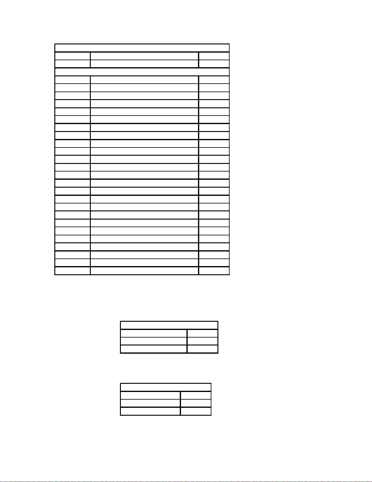
15.5.1 Get Unit Configuration
The HOST initiates by sending the GET_UNIT_CONFIG command packet:
SOP DLL DC CMD AppDC EOP
If the command is received with out error the SDP-3 responds with the UNIT_CONFIG response packet:
Product IdSW
F1 1C 80 19 03 03 03 03 01 01 00 BE 25
SYS
SW MJ
SW MN
PTCL
PTCL
PARAM
Time
39 38 2F 30 36 2F 32 36 20 30 39 3A 35 39 00 00 F2
Time
Time
Time
Time
Time
Time
Time
Time
Time
Time
Time
Time
Time
Time
Time
From the response packet we can see that the SDP-3 is configured as a
Product Id is JBL Synthesis SDP-3
Software type DTS
Software level of alpha
Software Version 3.01
Protocol Version 1.00
with 190 system parameters
and 37 effects,
and the ROM was built
“98/06/26 09:59”
41 of 41
Page 42

SerialDef,SDP-3.doc printed on 1/17/02
SOP
DLL DC
CMD
App DC
DATA0
EOP
EffectId
F1041B010F
F2
SOP
DLL DC
CMD
App DC
DATA0
DATA1
EffectId
Params
F11385100F
16
DATA2
DATA3
DATA4
DATA5
DATA6
DATA7
DATA8
DATA9
DATA10
DATA11
DATA12
DATA13
DATA14
DATA15
EOP
Name[0]
Name[1]
Name[2]
Name[3]
Name[4]
Name[5]
Name[6]
Name[7]
Name[8]
Name[9]
Name[10]
Name[11]
Name[12]
Name[13]
LOGIC
(sp)7(sp)
(sp)
(sp)
(sp)
(sp)
(sp)
00
SOP
DLL DC
CMD
App DC
DATA0
DATA1
DATA2
DATA3
DATA4
DATA5
DATA6
DATA7
DATA8
DATA9
EOP
InputId
Params
Name[0]
Name[1]
Name[2]
Name[3]
Name[4]
Name[5]
Name[6]
Name[7]
MY(sp)INPUT0
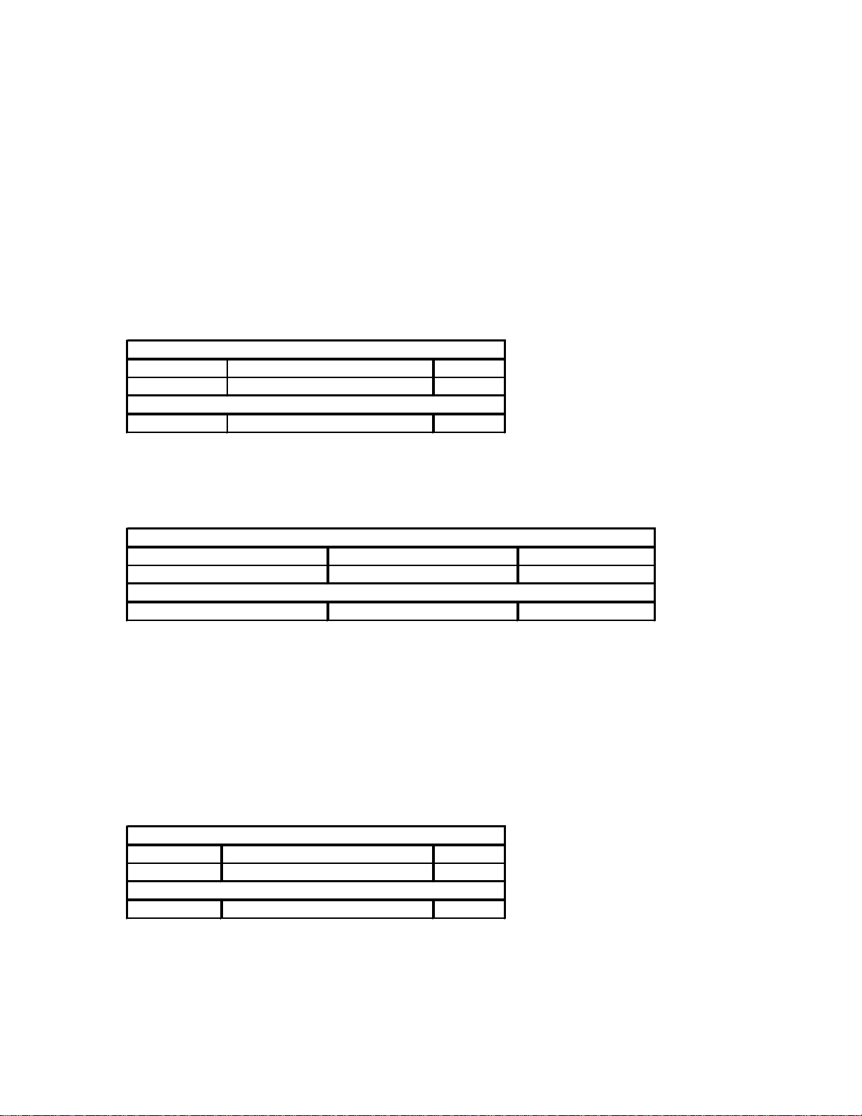
15.5.2 Get Effect Definition
Once we know how many effects the SDP-3 has resident we can then start to step through each effect for its definition. This is done by sending a GET_EFFECT
command packet:
The SDP-3 responds with a DC_RESP_EFFECT_DEF packet:
Max
Effect
4C 4F 47 49 43 20 37 20 20 20 20 20 20 00 F2
Effect
Effect
Effect
Effect
Effect
Effect
Effect
Effect
Effect
Effect
Effect
Effect
Effect
Here we can see that we requested effect number 16 and the SDP-3 responded with the effect number 16 definition. Effect 16 has 22 parameters and it is currently
named “LOGIC 7”. Note there are trailing spaces.
15.5.3 Set Input Name
In order to change an Input name all we must do is send a DC_CMD_SET_INPUT_NAME packet:
Max
Input
Input
Input
Input
Input
Input
Input
Input
F1 0D 2E 0A 03 4D 59 20 49 4E 50 55 54 00 F2
42 of 42
Page 43

SerialDef,SDP-3.doc printed on 1/17/02
SOP
DLL DC
CMD
App DC
DATA0
EOP
Cmd
F104E0012E
F2
Code
F104140117
F2
Here we see that we are telling the SDP-3 to change the AUX(3) input to be renamed as “MY INPUT”.
Because the SDP-3 received and processed the command successfully the SDP-3 responds with the DC_ACK packet. Here we see that the ACK packet is
responding to the DC_CMD_SET_INPUT_NAME command.
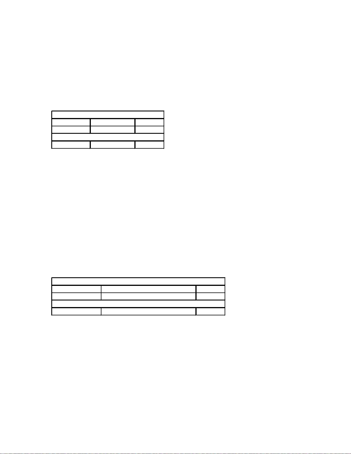
15.5.4 Send IR Command Example
SOP DLL DC CMD AppDC
IR Key
This example shows how to transmit the IR command for “Volume Up”. The bytes are transmitted from left to right and they are defined as:
Byte 0: Start of Packet(F1 hex)
Byte 1: Data Link Layer(DLL) Data Count(DC); for an IR command this would be 4 bytes to follow
Byte 2: The Application Layer Command, in this case it is 14 hex indicating this is an IR command packet.
Byte 3: The Application Layer Data Count(DC); for this packet it is 1 data byte to follow.
Byte 4: The Application Command Data: This IR Command Packet is transmitting Key Code “Volume Up”(17 hex). To transmit other IR Key Codes the
user would replace this byte with other IR key codes as found in Appendix C SDP-3 IR-Codes.
Byte 5: End of Packet (F2 hex)
43 of 43
 Loading...