

JBL SYNTHESIS-DIGITAL ACOUSTIC CALIBRATION SYSTEM, SDEC 1000, SDEC1000A, SDEC 2500, SDEC 2500A User Manual
Page 1

D
IGITAL
A
COUSTIC
C
ALIBRATION
(DACS)
♦
♦
♦♦
I
NSTALLER'S
S
YSTEM
M
ANUAL
Page 2

Page 3

Table of Contents
TABLE OF FIGURES............................................................................................ 5
.
.
.
.
.
.
.
.
.
.
.
.
.
.
.
.
.
.
.
.
.
.
.
.
.
.
.
.
.
.
.
.
.
.
.
.
.
.
.
.
.
.
.
.
.
.
.
.
.
.
.
.
.
.
.
.
.
.
.
.
.
.
.
.
.
.
.
.
.
.
.
.
.
.
.
.
.
.
.
.
.
.
S
E
C
T
I
O
N
1
-
I
N
T
R
O
D
U
C
T
I
O
N
.
.
.
.
.
.
.
.
.
.
.
.
.
.
.
.
.
.
.
.
.
.
.
.
.
.
.
.
.
.
.
.
.
.
.
.
.
.
.
.
.
.
.
.
.
.
.
.
.
.
.
.
.
.
.
.
.
.
.
.
.
.
.
.
.
.
.
.
.
.
.
.
.
.
S
E
C
T
I
O
N
1
-
I
N
T
R
O
D
U
C
T
I
O
N
.
.
.
.
.
.
.
.
.
.
.
.
.
.
.
.
.
.
.
.
.
.
.
.
.
.
.
.
.
.
.
.
.
.
.
.
.
.
.
.
.
.
.
.
.
.
.
.
.
.
.
.
.
.
.
.
.
.
.
.
.
.
.
.
.
S
E
C
T
I
O
N
1
-
I
N
T
R
O
D
U
C
T
I
O
N
NEED HELP? CALL. . . ............................................................................................ 7
SHIPPING TO THE NEXT DEALER............................................................................ 7
.
.
.
.
.
.
.
.
.
.
KIT INVENTORY ................................................................................................. 9
HARDWARE ........................................................................................................... 9
CABLES................................................................................................................. 9
IF SOMETHING IS MISSING OR DAMAGED ............................................................... 9
S
E
C
T
I
O
N
2
-
S
Y
S
T
E
M
I
N
S
T
A
L
L
A
T
I
O
N
S
E
C
T
I
O
N
2
-
S
Y
S
T
E
M
I
N
S
T
A
L
L
S
E
C
T
I
O
N
2
-
S
Y
S
T
E
M
I
N
A
S
T
A
L
L
A
N
T
I
O
N
N
T
I
O
N
N
.
.
.
.
.
.
.
.
.
.
.
.
.
.
.
.
.
.
.
.
.
.
.
.
.
.
.
.
.
.
.
.
.
.
.
.
.
.
.
.
.
.
.
.
.
.
.
.
.
.
.
.
.
.
O
T
E
S
.
.
.
.
.
.
.
.
.
.
.
.
.
.
.
.
.
.
.
.
.
.
.
.
.
.
.
.
.
.
.
.
.
.
.
.
.
.
.
.
.
.
.
.
.
O
T
E
S
.
.
.
.
.
.
.
.
.
.
.
.
.
.
.
.
.
.
.
.
.
.
.
.
.
.
.
.
.
.
.
.
.
.
.
.
O
T
E
S
.
.
.
.
.
.
.
.
.
.
.
.
.
.
.
.
.
.
.
.
.
.
.
.
.
.
.
.
.
SPEAKER PLACEMENT RULES .......................................................................... 11
CENTER MAIN....................................................................................................... 11
LEFT AND RIGHT MAINS........................................................................................12
SUBWOOFERS ......................................................................................................12
SURROUND SPEAKERS .........................................................................................12
W
ALL MOUNT
C
EILING MOUNT
.........................................................................................................12
......................................................................................................13
SYSTEM INTERCONNECTION DIAGRAMS .......................................................... 14
AMPLIFIER AND SDEC SWITCH SETTINGS..............................................................18
S
E
C
T
I
O
N
3
-
-
P
R
E
C
A
L
I
B
R
S
E
C
T
I
O
N
3
-
-
P
R
E
S
E
C
T
I
O
N
3
-
C
-
P
R
E
C
A
A
L
I
B
R
A
A
L
I
B
R
.
.
.
.
.
.
.
.
.
.
.
.
.
.
.
.
.
.
.
.
.
.
.
.
.
.
.
.
.
.
.
.
.
.
.
.
.
.
.
.
.
.
.
.
.
.
.
.
.
.
.
.
.
.
.
.
.
.
.
.
.
.
.
.
.
.
.
.
.
.
T
I
O
N
.
.
.
.
.
.
.
.
.
.
.
.
.
.
.
.
.
.
.
.
.
.
.
.
.
.
.
.
.
.
.
.
.
.
.
.
.
.
.
.
.
.
.
.
.
.
.
.
.
.
.
.
.
.
.
.
.
.
.
.
.
T
I
O
N
.
.
.
.
.
.
.
.
.
.
.
.
.
.
.
.
.
.
.
.
.
.
.
.
.
.
.
.
.
.
.
.
.
.
.
.
.
.
.
.
.
.
.
.
.
.
.
.
.
.
.
.
A
T
I
O
N
.
.
.
.
.
.
.
.
.
.
.
.
.
.
.
.
.
.
.
.
.
.
.
.
.
.
.
.
.
7
.
.
.
.
.
.
.
.
.
.
.
.
.
.
.
.
.
.
.
.
1
1
.
.
.
.
.
1
.
.
.
.
.
.
1
.
.
.
.
.
1
9
.
.
.
.
.
1
.
.
.
.
.
.
1
7
7
1
1
9
9
RESTORE PROCESSOR DEFAULT SETTINGS..................................................... 19
SPEAKER PHASE TESTS................................................................................... 20
ALTERNATE PHASE TEST METHOD ........................................................................20
Correct Speaker Phase................................................................................................21
S
YNTHESIS ONE
S
YNTHESIS TWO
S
YNTHESIS THREE
Surround Speakers ..................................................................................................... 21
USING THE PHASE TESTER ................................................................................... 22
Cricket-S................................................................................................................... 22
Cricket-R...................................................................................................................22
TEST THE PHASE TESTER.....................................................................................23
Sender Test ............................................................................................................... 23
Receiver Test ............................................................................................................23
Send-Receive Loop Test..............................................................................................23
: ....................................................................................................21
: ....................................................................................................21
: .................................................................................................21
SOUND CHECK................................................................................................. 24
SYNTHESIS ONE ................................................................................................... 24
SYNTHESIS TWO & THREE ....................................................................................24
Confirm Cinema to Music Mode Change .........................................................................24
USING THE SOUND LEVEL METER .................................................................... 25
ANALOG SLM USE INSTRUCTIONS .........................................................................25
DIGITAL SLM USE INSTRUCTIONS........................................................................... 26
Page 4

CORRECTING HUM PROBLEMS..........................................................................27
WHAT IS THE ORIGIN OF HUM?............................................................................. 27
DURING INSTALLATION: ....................................................................................... 27
VIDEO DEVICES: .................................................................................................. 28
S
E
C
T
I
O
N
4
-
U
S
I
N
S
E
C
T
I
O
N
4
S
E
C
T
I
O
N
4
G
-
U
S
I
N
-
G
U
S
I
N
G
4
.
.
.
.
.
.
.
.
.
.
.
.
.
.
.
.
.
.
.
.
.
.
.
.
.
.
.
.
.
.
.
.
.
.
.
.
.
.
.
.
.
.
.
.
.
.
.
.
.
.
.
.
.
.
.
.
.
.
.
.
.
.
.
.
.
.
.
.
.
.
.
.
.
.
.
.
.
.
.
.
.
.
.
D
A
C
S
4
.
.
.
.
.
.
.
.
.
.
.
.
.
.
.
.
.
.
.
.
.
.
.
.
.
.
.
.
.
.
.
.
.
.
.
.
.
.
.
.
.
.
.
.
.
.
.
.
.
.
.
.
.
.
.
.
.
.
.
.
.
.
.
.
.
.
.
.
.
.
.
.
.
.
D
A
C
S
4
.
.
.
.
.
.
.
.
.
.
.
.
.
.
.
.
.
.
.
.
.
.
.
.
.
.
.
.
.
.
.
.
.
.
.
.
.
.
.
.
.
.
.
.
.
.
.
.
.
.
.
.
.
.
.
.
.
.
.
.
.
.
.
.
.
D
A
C
S
.
.
.
.
.
.
.
.
.
.
.
2
.
.
.
.
.
.
.
.
2
.
.
.
.
.
.
.
.
2
INTRODUCTION ................................................................................................29
ABOUT DATA ACQUISITION................................................................................... 29
ABOUT DATA PROCESSING................................................................................... 30
SDEC PROGRAMMING........................................................................................... 30
About Target Curves ...................................................................................................30
CONNECTING DACS4 TO THE SYSTEM .................................................................. 31
BEST LOCATION FOR THE DACS ANALYZER .......................................................... 32
Power Connections .....................................................................................................32
P
OWERING-UP THE
M
ICROPHONE PLACEMENT
DACS4 SOFTWARE OPERATION ............................................................................ 34
Customer Information Window ...................................................................................... 35
S
ELECT SURROUND PROCESSOR
S
ELECT SCREEN COMPENSATION
DACS4 Connection Confirmation Screen ........................................................................37
DACS4 Main Screen Communication Fields .................................................................... 38
R
ESPONSE GRAPH
F
ILTER SETTINGS
P
RECISION FILTER ADJUSTMENT
C
HANNEL AND MODE SELECTION/STATUS
P
REVIOUSLY TESTED CHANNEL OVERLAY CONTROL
O
NLINE HELP
Function Keys
C
HANNEL GAIN
S
YSTEM STATUS
S T E P - B Y - S T E P C A L I B R A T I O N ................................................................. 43
Auto-Time Correction .................................................................................................. 43
Subwoofer Calibration .................................................................................................44
R
UN A LEVEL TEST
R
UN AUTO
Left-Center-Right Calibration........................................................................................46
S
ET THE LEVEL
A
UTO
Surround Calibration ...................................................................................................47
S
ET THE LEVEL
A
UTO
Music Mode Calibration ...............................................................................................47
Quitting DACS4 ..........................................................................................................48
Test Channel-to-Channel Balance .................................................................................48
W
HY USE THE
Quitting Before All Channels Are Accepted...................................................................... 49
-EQ .......................................................................................................45
-EQ..............................................................................................................46
-EQ..............................................................................................................47
DACS S
.........................................................................................33
cccc ................................................................................................39
dddd .................................................................................................39
hhhh ......................................................................................................41
iiii
.........................................................................................42
& D
jjjj ..................................................................................................42
.......................................................................................................46
......................................................................................................47
SLM?................................................................................................48
...........................................................................................42
ELAY
..................................................................................................45
.............................................................................32
YSTEM
.................................................................................36
................................................................................36
eeee ..............................................................................40
ffff ...................................................................40
gggg ...................................................... 41
9
9
9
3
Page 5

S
E
C
T
I
O
N
5
-
S
D
E
C
1
0
0
0
/
2
5
0
0
.
.
.
.
.
.
.
.
.
.
.
.
.
.
.
.
.
.
.
.
.
.
.
.
.
.
.
.
.
.
.
.
.
.
.
.
.
.
.
.
.
.
.
.
.
.
.
.
.
.
.
.
.
.
.
.
.
.
.
.
.
.
.
.
.
.
.
.
.
.
.
.
.
.
.
5
S
E
C
T
I
O
N
5
-
S
D
E
C
1
0
0
0
/
2
5
0
0
.
.
.
.
.
.
.
.
.
.
.
.
.
.
.
.
.
.
.
.
.
.
.
.
.
.
.
.
.
.
.
.
.
.
.
.
.
.
.
.
.
.
.
.
.
.
.
.
.
.
.
.
.
.
.
.
.
.
.
.
.
.
.
.
.
.
.
.
.
S
E
C
T
I
O
N
5
-
S
D
E
C
1
0
0
0
/
2
5
0
0
.
.
.
.
.
.
.
.
.
.
.
.
.
.
.
.
.
.
.
.
.
.
.
.
.
.
.
.
.
.
.
.
.
.
.
.
.
.
.
.
.
.
.
.
.
.
.
.
.
.
.
.
.
.
.
.
.
.
.
.
.
.
.
.
.
.
.
.
.
.
1
.
.
.
.
.
5
.
.
.
.
.
.
5
INTRODUCTION................................................................................................ 51
GAIN ....................................................................................................................51
Test for Optimum Gain ................................................................................................52
Determine Gain Error - L-C-R and Surrounds .................................................................. 52
Determine Gain Error - Subwoofers ...............................................................................53
SENSITIVITY......................................................................................................... 54
Test for Optimum Sensitivity ........................................................................................ 54
I
F YOU CAN SEE THE
I
F YOU CANNOT SEE THE
MAKING ADJUSTMENTS.........................................................................................57
Using the Gain and Attenuation Switches ....................................................................... 58
S
WITCH MATRIX
I
NCREASING GAIN
R
EDUCING GAIN
R
EDUCING SENSITIVITY
Factory DIP Switch Settings.........................................................................................59
SDEC D
.....................................................................................................58
...................................................................................................58
.....................................................................................................59
URING TEST
SDEC D
............................................................................................59
URING TEST
...................................................................55
..............................................................55
LOADER UTILITY .............................................................................................. 60
WINDOWS™ 3.1X .................................................................................................. 60
WIN 95/98™ .......................................................................................................... 60
S
E
C
T
I
O
N
6
-
S
E
C
T
I
S
O
E
C
T
I
O
HOOKUP............................................................................................................... 61
N
6
-
N
6
-
2
D
D
D
A
C
S
R
E
F
E
2
A
C
S
2
A
C
S
R
R
E
F
E
R
R
E
F
E
R
.
.
.
.
.
.
.
.
.
.
.
.
.
.
.
.
.
.
.
.
.
.
.
.
.
.
.
.
.
.
.
.
.
.
.
.
.
.
.
.
.
.
.
.
.
.
.
.
.
.
.
.
.
.
.
.
.
.
.
.
.
.
.
.
.
.
.
.
.
.
.
.
.
.
6
E
N
C
E
.
.
.
.
.
.
.
.
.
.
.
.
.
.
.
.
.
.
.
.
.
.
.
.
.
.
.
.
.
.
.
.
.
.
.
.
.
.
.
.
.
.
.
.
.
.
.
.
.
.
.
.
.
.
.
.
.
.
.
.
.
.
.
.
.
.
.
.
E
N
C
E
.
.
.
.
.
.
.
.
.
.
.
.
.
.
.
.
.
.
.
.
.
.
.
.
.
.
.
.
.
.
.
.
.
.
.
.
.
.
.
.
.
.
.
.
.
.
.
.
.
.
.
.
.
.
.
.
.
.
.
E
N
C
E
.
.
.
.
.
.
.
.
.
.
1
.
.
.
.
.
6
.
.
.
.
.
.
6
ANALOG EQ/CROSSOVER SYSTEMS ................................................................. 62
SYNTHESIS ONE FACTORY EQ SETTINGS .............................................................. 62
SYNTHESIS ONE CROSSOVER FACTORY SETTINGS................................................63
Cinema Mode ............................................................................................................ 63
LOW OUTPUT MUTE: Off (out) ..................................................................................... 63
Music Mode ..............................................................................................................64
LOW OUTPUT MUTE: OFF (OUT)............................................................................. 64
SYNTHESIS ONE CABLE SPECIFICATIONS.............................................................. 65
S
E
C
S
E
C
S
E
C
7
-
T
I
O
T
I
O
T
I
O
S
N
N
N
U
B
J
E
7
-
S
7
-
S
C
U
B
J
E
C
U
B
J
E
P
T
I
V
E
E
R
F
O
R
M
P
T
I
V
E
E
R
C
P
T
I
V
E
E
R
A
F
O
R
M
F
O
R
M
E
N
C
E
V
A
L
U
E
A
N
C
E
E
A
N
C
E
A
V
A
L
U
V
A
L
U
.
.
.
.
.
.
.
.
.
.
.
.
.
.
.
.
.
.
.
.
.
.
.
.
.
.
.
.
.
.
.
.
.
.
.
.
.
.
.
.
.
.
.
.
.
.
.
6
T
I
O
N
.
.
.
.
.
.
.
.
.
.
.
.
.
.
.
.
.
.
.
.
.
.
.
.
.
.
.
.
.
.
.
.
.
.
.
.
.
.
.
.
.
A
T
I
O
N
.
.
.
.
.
.
.
.
.
.
.
.
.
.
.
.
.
.
.
.
.
.
.
.
.
.
.
.
.
.
.
.
A
T
I
O
N
.
.
.
.
.
.
.
.
.
.
7
.
.
.
.
.
6
.
.
.
.
.
.
6
1
1
1
1
7
7
DELOS
TEST CD.............................................................................................. 67
®
Track 36, Continuous Wide-band Frontal Pan .................................................................67
Track 37, Stepped Wide-band Frontal Pan...................................................................... 67
DELOS® DVD SPECTACULAR ............................................................................ 67
Tracks 10-15, Sine Sweep ...........................................................................................67
Track 16, Pink Noise, Continuous Pan (5.1) ...................................................................67
Tracks 2-5, Dolby™ trailers..........................................................................................67
3
Page 6

Page 7

ABLE OF FIGURES
T
F
F
F
F
F
F
F
F
F
F
F
F
F
F
F
F
F
F
F
F
F
F
F
F
F
F
F
F
F
F
F
F
F
F
F
F
F
F
F
F
F
F
F
F
F
F
1: S
IGURE
IGURE
IGURE
IGURE 4: SYNTHESIS ONE INTERCONNECT WIRING DIAGRAM
IGURE
IGURE
IGURE
IGURE
IGURE
IGURE
IGURE
IGURE
IGURE
IGURE
IGURE
IGURE
IGURE
IGURE
IGURE
IGURE
IGURE
IGURE
IGURE
IGURE
IGURE
IGURE
IGURE
IGURE
IGURE
IGURE
IGURE
IGURE
IGURE
IGURE
IGURE
IGURE
IGURE
IGURE
IGURE
IGURE
IGURE
IGURE
IGURE
IGURE
IGURE
IGURE
YNTHESIS TWO AND THREE CONTROL WIRING DIAGRAM
YNTHESIS TWO AND THREE INTERCONNECT WIRING DIAGRAM
2: S
YNTHESIS ONE CONTROL WIRING DIAGRAM
3: S
5: C
OMPONENT SWITCH SETTINGS
7: G
ALAXY AUDIO PHASE TESTER
8: 59: SLM F
10: C
11: D
12: S
13: T
14: DACS4
15: M
16: DACS O
17: C
18: C
19: S
20: S
21: DACS4 ON S
22: DACS4 M
23: R
24: F
25: F
26: D
27: C
28: C
29: F
30: C
31: S
32: F
33: A
34: DACS4
35: L
36: R
37: L
38: A
39: T
40: E
41: SDEC
42: SDEC G
43: B
44: S
45: DACS2
46: S
47: C
DIN
PIN
ONTROL LOCATIONS
IGITAL
PATIALLY AVERAGED SYSTEM RESPONSE
YPICAL TARGET CURVE
ICROPHONE PLACEMENT
USTOMER INFORMATION WINDOW
USTOMER INFORMATION
ELECT A SURROUND PROCESSOR
ELECT SCREEN COMPENSATION
ESPONSE GRAPH WINDOW
ILTER SETTING AND CONTROL FIELD
ILTER CONTROL FIELD
IRECT CHANNEL AND MODE ACCESS
HANNEL DISPLAY CONTROL FIELD
ONTINUOUSLY UPDATED ONLINE HELP
UNCTION KEYS
HANNEL GAIN AND DELAY DIALOG BOX
YSTEM STATUS DELAY
RESH INSTALL
UTO-TIME CORRECTION DIALOG BOX
EFT
ESPONSE AFTER AUTO
EFT CINEMA LEVEL SET
UTO
YPICAL SURROUND TARGET
ARLY QUIT WARNINGS
ASIC GAIN/ATTENUATION SETTINGS
WITCH MATRIX
YNTHESIS ONE FACTORY
ABLE DIAGRAMS
TO PHOENIX ADAPTER
ACEPLATE
_____________________________________________________________ 25
_________________________________________________________ 25
SLM _______________________________________________________________ 26
_______________________________________________________ 30
HOOKUP DIAGRAM
_____________________________________________________ 31
_____________________________________________________ 33
PENING SCREEN
______________________________________________________ 34
: S
CREEN WIRING DIAGRAM
AIN SCREEN
________________________________________________________ 38
_______________________________________________________ 40
_____________________________________________________________ 42
_______________________________________________________ 42
, F
IRST SCREEN
READY FOR SUBWOOFER LEVEL TEST
: PRE-EQ
RESPONSE
. R
-EQ ____________________________________________________ 45
______________________________________________________ 46
EQ [F3]: A
CCEPTS SETTINGS
_______________________________________________________ 49
SENSITIVITY OPTIMIZATION FLOWCHART
AIN SWITCH LOCATOR
_____________________________________________________________ 58
ON SCREEN WIRING DIAGRAM
EQ
_____________________________________________________________ 65
__________________________________________________ 18
.___________________________________________________ 22
_________________________________________________ 24
_______________________________________________ 35
ELECT A SYNTHESIS MODEL
_______________________________________________ 36
________________________________________________ 36
____________________________________________________ 39
______________________________________________ 41
_________________________________________________ 43
: PRE-EQ
IGHT
. _____________________________________________ 46
___________________________________________________ 47
__________________________________________________ 57
______________________________________________ 58
SETTINGS
________________________________________ 16
. _________________________________________ 29
____________________________________________ 37
____________________________________________ 39
_____________________________________________ 40
___________________________________________ 41
___________________________________________ 42
____________________________________________ 43
_____________________________________________ 61
__________________________________________ 62
_______________________________ 14
__________________________ 15
____________________________________ 17
______________________________ 36
_______________________________________ 44
WITH DISPLAY SMOOTHING
______________________________________ 56
___________________ 45
Page 8

Page 9
I
N
T
R
O
D
U
C
T
I
O
S
E
C
T
I
O
N
1
-
S
E
C
T
I
O
N
S
E
C
T
I
O
This document contains reference materials pertaining to the use of the Synthesis Calibration
Kits. It is assumed that the reader is experienced in custom home theater installation and has
previously received instruction from JBL Synthesis personnel on the use of this equipment.
Safety related information will be highlighted with this symbol
Critical information will be highlighted with this symbol
N
1
1
-
I
N
T
R
O
D
U
C
-
I
N
T
R
O
D
U
C
T
T
N
O
O
N
N
I
I
Important notes and useful tips will be highlighted with this
****
S
E
C
T
I
O
N
1
S
E
C
T
S
E
C
T
S
E
C
T
I
S
E
C
T
S
E
C
T
S
E
C
T
I
S
E
C
T
S
E
C
T
S
E
C
T
I
S
E
C
T
S
E
C
T
S
E
C
T
I
S
E
C
T
S
E
C
T
S
E
C
T
I
S
E
C
T
S
E
C
T
S
E
C
T
I
S
E
C
T
S
E
C
T
I
O
N
1
I
O
O
I
O
I
O
O
I
O
I
O
O
I
O
I
O
O
I
O
I
O
O
I
O
I
O
O
I
O
I
O
Look here for general information about the calibration kit and this manual.
N
1
N
2
N
2
Provides information helpful during system installation.
N
2
N
3
N
3
Look here for pre-calibration routines and tests.
N
3
N
4
N
4
DACS4 short form user's guide.
N
4
N
5
N
5
SDEC loader utility, gain and sensitivity control information.
N
5
N
6
N
6
Analog EQ/Crossover equipped systems are covered here.
N
6
N
7
N
7
Subjective system performance testing.
N
7
****
N EED H ELP? CALL. . .
If you encounter problems that cannot be resolved using the information presented here,
please call your Synthesis Representative for further assistance.
Eric Leicht: 818.830.8705 or 818.259.4189
Chris Neumann: 818.895.5712 or 818.422.1045
Dan Siefert: 805.492.0773
S HIPPING T O T HE NEXT D EALER
By the time you have completed your Client's installation, you should have received a FAX
giving detailed shipping instructions. If you have not received this information, please call
immediately and request shipping information.
Unless otherwise instructed, always ship via UPS Blue.
****When shipping, always insure kit for $15,000.00
Page 10

Page 11

H ARDWARE
(1) Operators Handbook
(1) Laptop Computer
(1) Phase Tester (transmitter & receiver)
(5) Microphones
(1) Spare microphone
(5) Telescopic Microphone stanchions
(5) Stanchion bases
(1) MMX-5 Microphone Multiplexer
(1) Sound Level Meter
(1) External Vector Processor (EVP-1)
(1) EVP-1 Power Supply
(1) Delos Surround Spectacular Demo & Test disc
(1) Delos DVD Spectacular Demo & Test disc
(1) Tape Measure
C ABLES
(5) 6’ Microphone extension cables (F-XLR to M-XLR)
(1) 25’ Stereo audio cable (RCA to RCA)
( 1 ) 2 5 ’ M M X - 5 t o l a p t o p c a b l e (T707/T707) or (M-DB9 /T707) or (M-DB9 to M-DB9)
(1) 25’ Computer to SDEC (M-DB9 to F-DB9)
(1) 6’ Computer to EVP-1 (M-DB25 to M-DB25)
(1) 6’ Phase tester adapter (F-XLR to RCA)
(1) 25’ Instrumentation cable (BNC to BNC)
(1) 25’ Adapter cable (BNC to RCA)
(1) IEC AC power cord
(1) Computer AC power cord
(1) Male RCA to two female RCA "Y" adapter
IT INVENTORY
K
I F S OMETHING I S MISSING O R D AMAGED
If the contents of this kit do not match this list, something is damaged, or the case itself is
seriously damaged, contact your Synthesis Representative immediately and arrange for
replacement.
Eric Leicht: 818.830.8705 or 818.259.4189
Chris Neumann: 818.895.5712 or 818.422.1045
Dan Siefert: 805.492.0773
3
Page 12

Page 13

S
Y
S
T
E
M
I
N
S
T
A
L
L
A
T
I
O
N
S
S
S
E
E
E
C
C
C
T
T
T
I
I
I
O
O
O
N
N
N
2
-
2
2
-
S
Y
S
T
E
M
I
N
S
T
A
L
L
A
T
-
S
Y
S
T
E
M
I
N
S
T
A
L
L
N
O
T
E
S
N
N
O
O
T
T
E
E
S
S
A
T
I
I
O
O
N
N
PEAKER PLACEMENT RULES
S
1
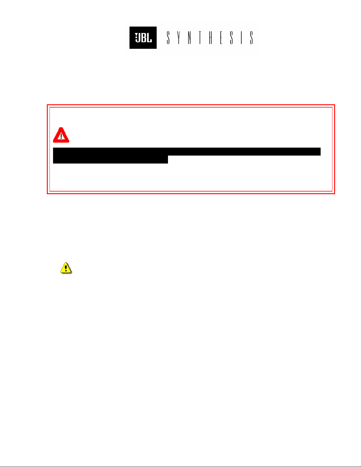
It is vitally important that any speakers mounted above the floor be
properly secured! Safety must come first. Never place speakers on a shelf
without an approved retaining mechanism. Never screw eye-loops or other
hardware directly into speaker cabinets. Unsecured or improperly secured
speakers represent a safety hazard which can result in serious injury.
1
The installation of any home theater system represents a balancing of aesthetic and functional
requirements which frequently are at odds with each other. The following information should
be used to optimize the placement of the speakers and achieve the best results while still
conforming to the architectural limitations inherent in the installation.
C ENTER M AIN
1. If the speaker is behind a perforated screen, place it as far forward as possible, nearly
touching the screen.
2. If it is above or below the screen, it must be placed as close as possible to the edge of the
screen, along the same plane as the screen.
3. If it is on a shelf, in a pre-fabricated hole in the wall or in a cabinet opening, place it as far
forward as possible.
3.1. Any gap around the speaker must be filled. If the gap is ½" closed-cell foam can be
used. For gaps greater than ½" it is recommended that you "frame" the speaker with ≈ ¾"
MDF, plywood or other solid panel material.
4. Do not allow anything to obstruct the baffle area of the speakers.
4.1. If decorative cloth is placed in front of the speakers, be sure the frame for the cloth
does not obstruct the front of the speaker.
3
Page 14
L EFT AND R IGHT M AINS
1. If the speaker is on a shelf, in a pre-fabricated hole in the wall or in a cabinet opening,
place it as far forward as possible.
1.1. Any gap around the speaker must be filled. If the gap is ½" closed-cell foam can be
used. For gaps greater than ½" it is recommended that you "frame" the speaker with ≈ ¾"
MDF, plywood or other solid panel material.
2. Do not allow anything to obstruct the baffle area of the speakers.
2.1. If decorative cloth is placed in front of the speakers, be sure the frame for the cloth
does not obstruct the front of the speaker.
S UBWOOFERS
1. In nearly all cases, the best location for subwoofers is on the floor, in the front corners of
the room. Place them with the woofers facing the listening area.
1.1. If the subwoofers cannot be placed in the corners, the next best position is on the
floor, against the front wall. In this instance, better low frequency coupling may be
achieved by turning the subwoofers sideways such that the drivers and ports are next to
the front wall.
2. If the subwoofers are placed in a pre-fabricated hole in the wall or in a cabinet opening,
place them as far forward (toward the opening) as possible.
2.1. Any gap around the subwoofer must be filled. If the gap is ½" closed-cell foam can
be used. For gaps greater than ½" it is recommended that you "frame" the speaker with
≈ ¾" MDF, plywood or other solid panel material.
2.2.
2.3. If decorative cloth is placed in front of the speakers, be sure the frame for the cloth
does not obstruct the driver or ports of the subwoofers.
Do not allow anything to obstruct the driver or ports of any speakers.
S URROUND S PEAKERS
Wall Mount
1. Side surround speakers are to be mounted vertically and placed directly at the sides of the
listening area.
2. Rear surround speakers are to be mounted vertically and placed on the rear wall of the
listening area.
3. The bottom edge of all surround speakers must be at least 24" above ear level.
3.1. Avoid elevating surround speakers more than 48" above ear level.
4. If the speaker is on a shelf, minimize the width and depth of the shelf as much as possible.
4.1. Place them against the wall.
5. If they are placed in a pre-fabricated hole in the wall or cabinet opening, it must exceed the
speaker width by no less than 24".
5.1. Center the speaker in the opening.
5.2. Any open area behind the speaker must be filled to minimize acoustic resonances.
6.
Do not allow anything to obstruct the drivers.
6.1. If decorative cloth is placed in front of the speakers, be sure the frame for the cloth
does not obstruct the drivers.
3
Page 15
Ceiling Mount
1
TAKE NO CHANCES!
The mounting hardware provided with Synthesis surround speakers
IS NOT
suitable for ceiling installation. Improperly suspended speakers represent
a serious safety hazard which can result in injury or death.
1
1. Side surround speakers are to be mounted with the top of the enclosure facing the center of
the room, as near to the adjacent wall as possible.
2. Rear surround speakers are to be mounted with the top of the enclosure facing the video
display screen, as near to the adjacent wall as possible.
3. If they are placed in a pre-fabricated hole or cutout in the ceiling, it must exceed the
speaker width by no less than 24".
3.1. Center the speaker in the opening.
3.2. Any open area behind the speaker must be filled to minimize acoustic resonances.
4.
Do not allow anything to obstruct the drivers.
4.1. If decorative cloth is placed in front of the speakers, be sure the frame for the cloth
does not obstruct the drivers.
3
Page 16
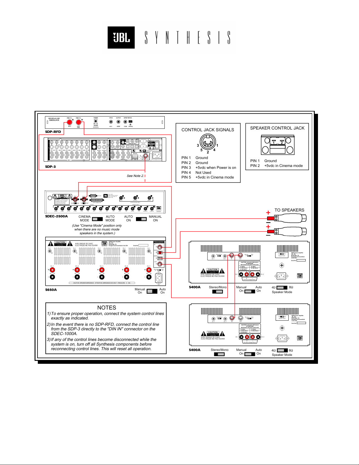
YSTEM INTERCONNECTION DIAGRAMS
S
Figure 2:
Synthesis Two and Three Control Wiring Diagram
3
Page 17
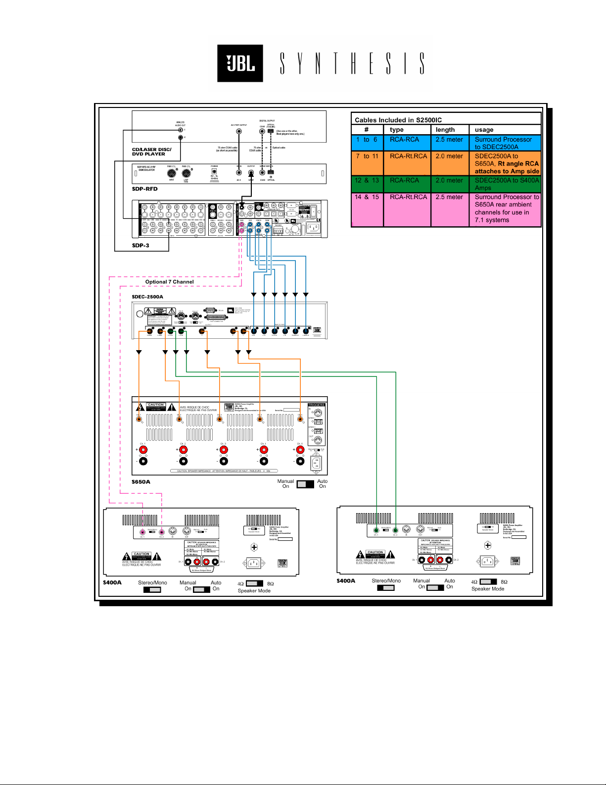
Figure 3:
Synthesis Two and Three Interconnect Wiring Diagram
3
Page 18
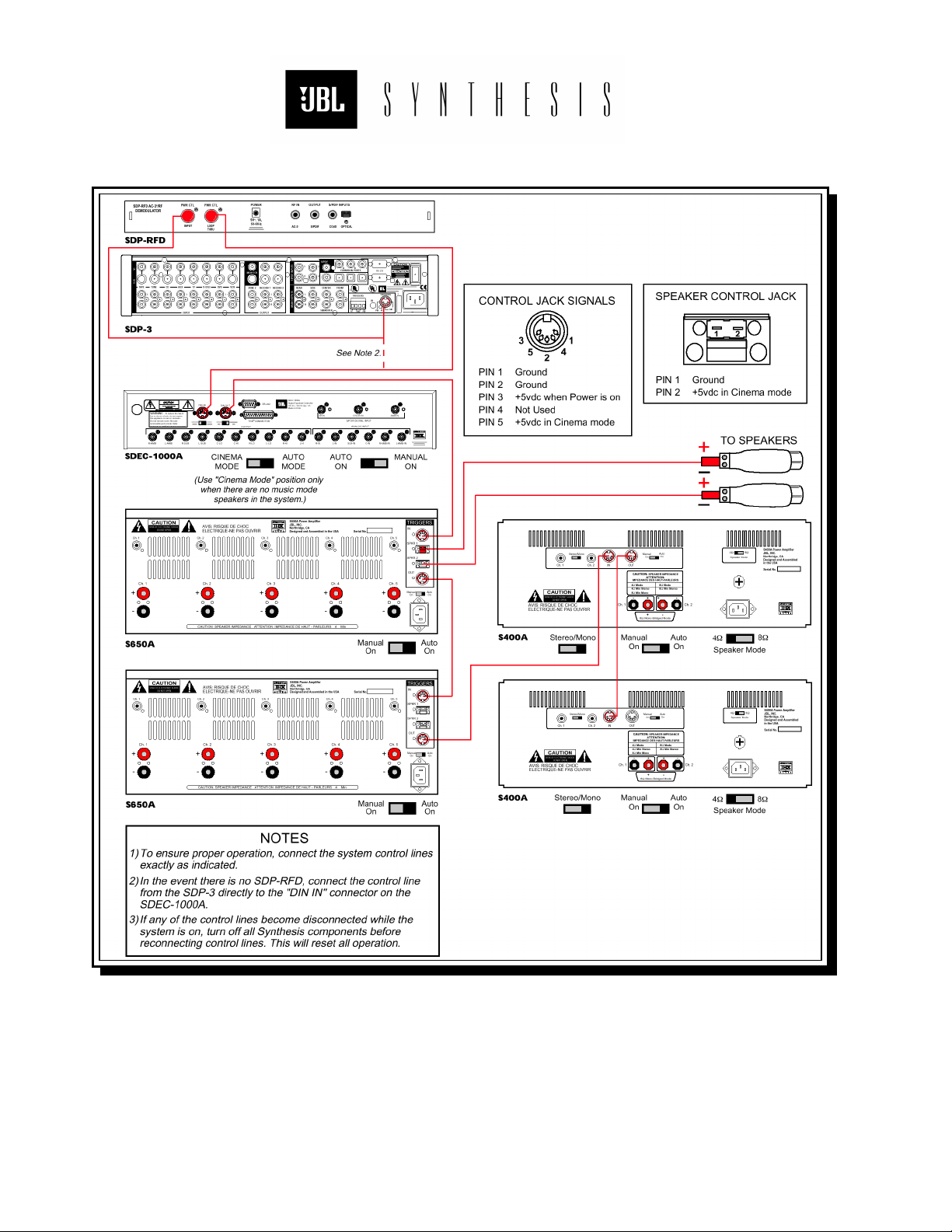
Figure 4:
Synthesis One Control Wiring Diagram
3
Page 19
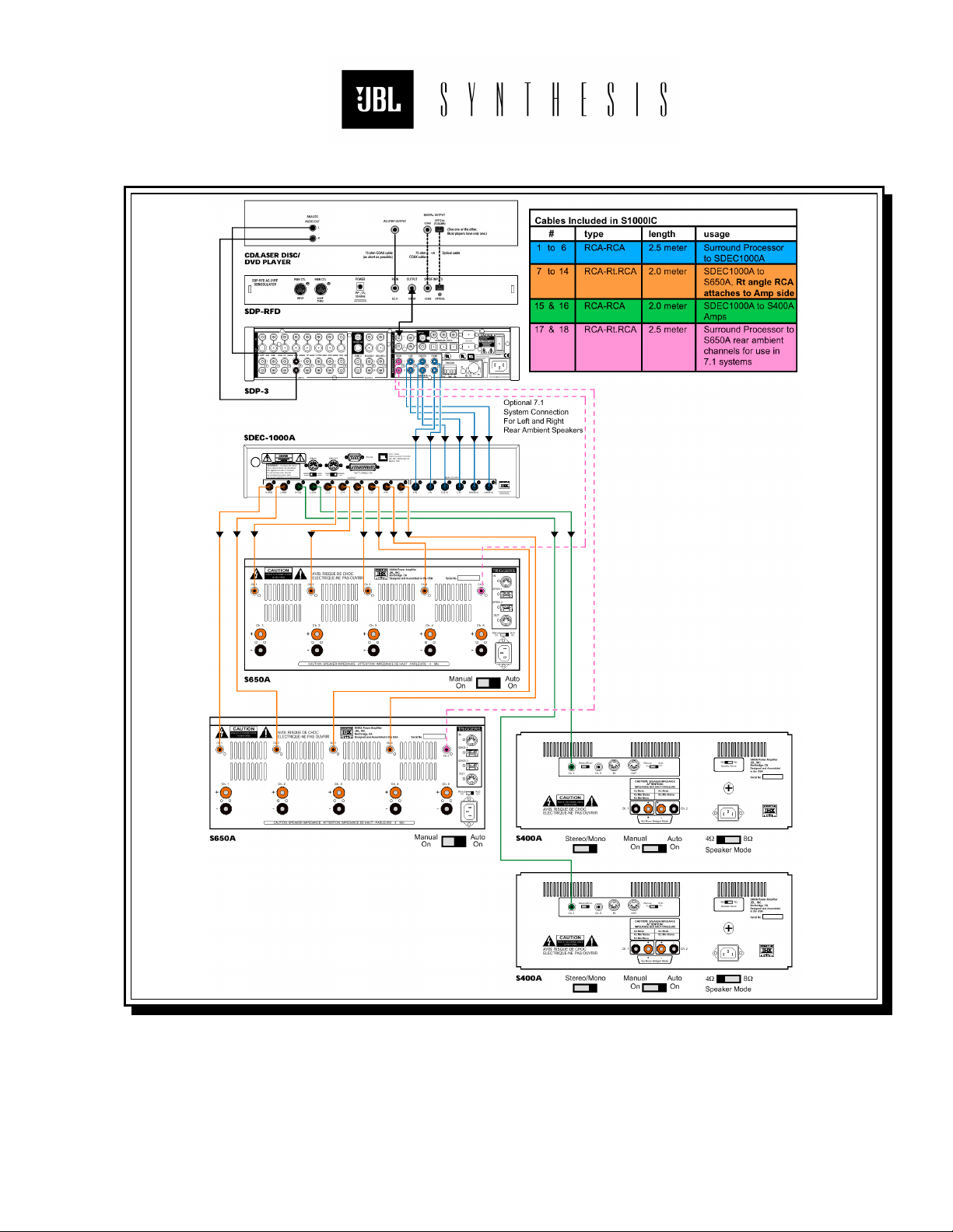
Figure 5:
Synthesis One Interconnect Wiring Diagram
3
Page 20
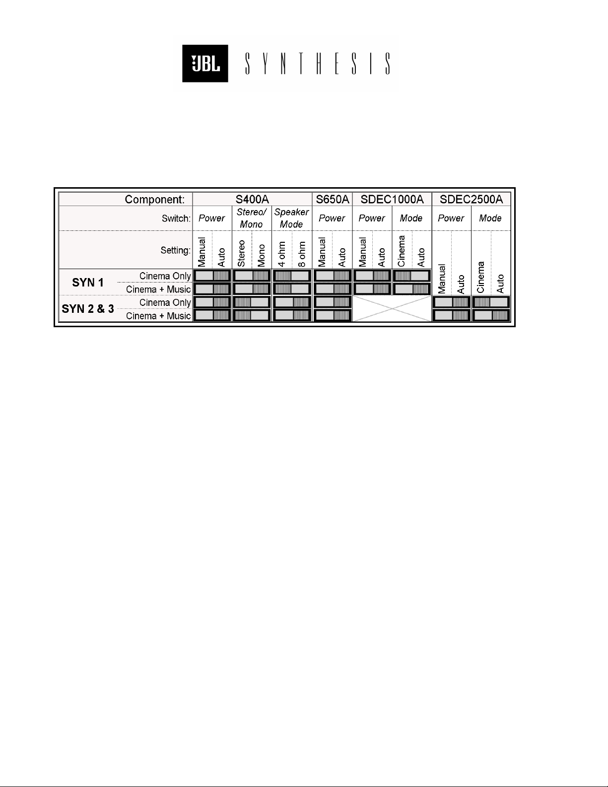
MPLIFIER AND SDEC SWITCH S ETTINGS
A
Figure 6: Component Switch Settings
3
Page 21

P
R
E
C
A
L
I
B
R
A
T
I
O
S
E
C
T
I
O
N
3
-
S
E
C
T
I
O
N
S
E
C
T
I
O
ESTORE PROCESSOR DEFAULT SETTINGS
R
This is applicable to all Synthesis models equipped with an SDP-2, SDP-2D or SDP-3
****
processor.
It is recommended that you restore the Surround Processor to the factory default settings
prior to system calibration. This will ensure that you do not waste time later troubleshooting
an apparent problem, only to find that the Processor settings were the cause.
1. Use the remote control to turn the processor OFF.
2. Use the remote to turn the processor back ON.
3. Immediately press and hold the MUTE button on the remote control.
4. In a few seconds, the "FACTORY PRESETS MENU" will appear on the Processor's readout.
5. Release the MUTE button.
6. Scroll to and select "RESTORE DEFAULTS".
7. When the message "FACTORY DEFAULTS RESTORED" is displayed press DONE to return
to normal operation.
Alternatively, you can adjust each setting manually. They should be set as follows:
A. Volume Control: 0dB
B. Speaker Configuration:
LEFT - CENTER – RIGHT: Small, 80Hz high-pass
LEFT & RIGHT SIDE: Small dipole, 80Hz high-pass.
BASS SPLIT: 80Hz
REARS: None
SUBWOOFER: Yes, Crossover = 80Hz.
C. All outputs levels set to 0.0dB
D. SUBWOOFER PEAK LIMITER: OFF
E. EQUALIZATION. . .
BASS: 0dB
TREBLE: 0dB
TILT: 0dB
LOUDNESS: OFF
F. LISTENER POSITION: 3’
G. PRO-LOGIC. . .
AUTO AZIMUTH: OFF
DIALOGUE ENHANCE: 0dB
EFFECT LEVEL: 0dB
SUBWOOFER LEVEL: 0dB
SURROUND LEVEL: 0dB
H. STEREO BYPASS. . .
SUBWOOFER LEVEL: 0dB
N
3
3
-
P
-
P
R
R
E
E
-
-
C
A
L
I
B
R
A
-
C
A
L
I
B
R
A
T
T
N
O
N
N
I
O
I
3
Page 22

PEAKER PHASE TESTS
S
For this operation, you will use the phase tester provided. If you are unfamiliar with this
instrument, refer to "U
Always turn the amplifier power off before changing input connections.
1. Use the supplied female XLR to RCA adapter cable provided in the kit.
2. Connect the phase tester's output to the amplifier input corresponding to the channel you
are going to test.
Sometimes access to the amplifier inputs is nearly impossible. In such situations, use
****
the "Alternate Phase Test Method" described below.
3. Power-up the amplifier and set the Cricket-S output level to low or high as required to get
a clearly audible click from the speaker.
4. Point the rear panel of the Cricket-R toward the driver and slowly move the receiver closer
to the speaker.
5. At a distance of approximately three to six inches from the driver you should begin to
observe a polarity indication. You may have to adjust the receiver's gain control to get a
stable, repeatable indication.
6. When the polarity indication is stable, check your test result against the phase table on
the next page.
SING THE PHASE TESTER
" on Pg.19.
A LTERNATE P HASE T EST METHOD
This procedure uses the Surround Processor to route the phase tester's output to the
appropriate channel for test. Using a "Y" adapter, connect the phase tester's output to both
channels of the TAPE input. Select the TAPE input, use the Surround Processor's volume
control to set the test level. Use the following table to route the signal as needed.
To Test. . . Use Mode. . .
LF and RF 2-CHANNEL
CF PRO-LOGIC
LA and RA PARTY
3
Page 23

Correct Speaker Phase
Use the phase tester to confirm the following driver polarities. . .
Synthesis One:
L-C-R Horns (+)
L-C-R Mid-bass drivers (+)
Subwoofers (+)
Synthesis Two:
L-C-R Main Horns (-)
L-C-R Main mid-bass drivers (+)
Subwoofers (+)
Synthesis Three:
L-C-R Main Horns (+)
Subwoofers (+)
Surround Speakers
Regardless of model, there are two acceptable methods of phasing the surround speakers.
CONFIGURATION ONE
preferable.
is the default method. In some installations,
Figure 6: Surround speaker polarity configurations
CONFIGURATION TWO
may be
3
Page 24

U SING T HE P HASE TESTER
Figure 7: Galaxy Audio phase tester.
The Galaxy Audio phase tester consists of two battery operated instruments, Cricket-S is the
"sender", Cricket-R is the "receiver".
Cricket-S
The sender generates a short duration, positive polarity pulse. This is applied to the power
amplifier input which drives the loudspeaker being tested. Coincident with the generation of
each pulse, a green LED is illuminated. Three output connectors are located on the rear
panel. Line level male XLR, line level female ¼" phone jack and a speaker level female ¼"
phone jack. A female XLR to RCA adapter cable is provided in the kit. Plug this cable into the
XLR connector and use it to connect the sender to each channel for test.
On the front panel are two slide switches and a pulse indicating LED. Slide the ON/OFF switch
to the ON position and the output selector to the LO position. You should now hear pops at
one second intervals from the speaker under test. If a higher level is required, set the output
selector to HI.
Cricket-R
The receiver contains a microphone and phase analysis circuitry. Positive polarity is indicated
by a green LED, negative by a red LED.
Two input connectors and the microphone are located on the rear panel. There is also a
switch marked "CON" (continuity) and "POL" (polarity). Place this switch in the "POL" position.
On the front panel are two slide switches, a rotary gain control and the two phase indicating
LEDs. Slide the right side switch to the ON position and place the left side switch in the MIC
position. Now move the receiver's microphone toward the speaker being tested. When you are
within three to six inches of the speaker you should begin to see a polarity indication. Adjust
the gain control until a consistent indication of phase is realized.
3
Page 25

T EST THE P HASE T ESTER
If you are having difficulty getting reliable phase information, or if the phase tester appears to
be inoperative, perform the following tests.
Sender Test
Turn the unit ON and select SPK (speaker) output. If the unit is working normally, you will
hear a "pop" from the speaker (located in the top cover) and see the green LED flash at about
one second intervals. If the unit does not work as described, replace the battery (standard 9V)
and try again.
Receiver Test
Turn the unit ON and select BAT (battery). The green LED should be fully illuminated;
indicating the battery is in good condition. If the LED is dim or does not light, replace the
battery.
Send-Receive Loop Test
Turn both units ON. Set the receiver on MIC input and put the sender's output selector in the
SPK position. Move the receiver's microphone one to two inches above the sender's speaker.
Adjust the receiver's gain control until it's green LED flashes reliably whenever a pop is heard
from the sender. This indicates that both phase test components are working correctly.
If you cannot get a reliable, consistent phase indication during this test, do not use to
measure the Synthesis speaker phase.
3
Page 26

OUND CHECK
S
S YNTHESIS O NE
1. Set the Processor to PRO-LOGIC mode.
2. Use the circulating noise generator of the Surround Processor to confirm that all channels
have output and that each speaker is connected to its corresponding channel.
3. Determine that the drivers of the Left Front (LF) Center Front (CF) and Right Front (RF)
channels are receiving the correct frequency range. Play track 36 of the Delos "Surround
Spectacular" test disk provided. Wide-band pink noise is continuously panned across the
three front channels.
a. Disconnect the horn tweeters of the LF-CF-RF speakers.
b. Temporarily turn the subwoofer amplifiers off.
c. Play track 36. Only the 8" drivers should play. All three should sound substantially
alike and should have considerable mid-range content. If one or all of them
sounds very thin, check your wiring.
d. Reconnect the tweeters and disconnect the mid-range speakers. Play track 36. All
three tweeters should sound substantially alike and should have no mid-range
content. If one of them sounds different from the others, check your wiring.
S YNTHESIS T WO & THREE
1. Set the Processor to PRO-LOGIC mode.
2. Use the circulating noise generator of the Surround Processor to confirm that all channels
have output and that each speaker is connected to its corresponding channel.
Confirm Cinema to Music Mode Change
(Cinema + Music systems only)
5 pin DIN style cables are used to communicate between Synthesis components. Check
now to confirm they are all properly routed and the connectors are well seated. The control
lines to the Left and Right main speakers are sometimes very long. To eliminate the difficulty
of acquiring unusually long DIN cables, each Synthesis system includes 5-pin DIN to 5mm
Phoenix connector adapters. The Phoenix connector will accept nearly any wire up to 18ga.
Figure 8: 5-pin DIN to Phoenix adapter
You may use these adapters to connect each main speaker to it's control line. The polarity of
the incoming wires is unimportant. Confirm that the wires are stripped at least ¼" and the
retaining screws are well tightened.
3
Page 27

SING THE SOUND LEVEL METER
U
Each calibration kit includes either an analog or digital Radio Shack sound level meter (SLM).
A NALOG SLM USE I NSTRUCTIONS
1. Rotate the RANGE Selector clockwise one click to the
BATTERY TEST position. Observe the meter indication.
A reading anywhere within the red BATT TEST range
indicates adequate battery power. If the indication is
below this range, replace the battery before using the
instrument.
2. Now rotate the RANGE Selector clockwise to the
desired range. The meter has a display range from
-10dB to +6dB. See Fig. 8. The 0dB point corresponds
to the RANGE selected. Therefore, if the 80dB RANGE
is selected, a 0dB reading will equal 80dB.
Figure 9: SLM Faceplate Figure 10: Control Locations
All instruments of this type are most accurate when operated in the upper end of the
****
selected range. You should always use the lowest RANGE setting possible. For example, if
you are balancing a system using the Surround Processor's noise generator (75dB) you
would set the RANGE selector to 70dB.
3. Slide the WEIGHTING Selector to "C" weighting for channel balance tests. "A" weighting
cuts low frequencies. This will cause errors when measuring subwoofers.
4. It is recommended that you slide the RESPONSE Selector to the SLOW position. This
slows the meters response to sudden changes in sound level which can make average
level readings difficult.
3
Page 28

D IGITAL SLM USE I NSTRUCTIONS
1. Turn the SLM on by rotating the RANGE Selector clockwise.
Continue to rotate the RANGE Selector to the desired
RANGE.
All instruments of this type are most accurate when
****
operated in the upper end of the selected range. You should
always use the lowest RANGE setting possible. For example,
if you are balancing a system using the Surround Processor's
noise generator (75dB) you would set the RANGE selector to
70dB.
In the event you have selected a range that is too low, an
OVER-RANGE condition is indicated by a flashing display.
Select the next higher range.
2. Press the WEIGHTING button to select "C" weighting for
channel balance tests.
3. It is recommended that you slide the RESPONSE Selector to
the SLOW position. This slows the meters response to sudden
changes in sound level which can make average level
readings difficult.
4. Check the display for a low battery indication. If the battery
needs replacing, BATT will appear in the upper left-hand
corner of the LCD display. Replace the battery if necessary.
Figure 11: Digital SLM
3
Page 29

ORRECTING HUM PROBLEMS
C
This information will help you avoid hum problems in any Synthesis Home Theater System
installation.
W HAT IS T HE ORIGIN OF H UM?
Whenever you interconnect two or more AC powered analog audio devices, you have the
potential to generate audible hum.
All audio signal devices must be referenced to “ground”. This connection establishes a zero
voltage “reference” point for the entire system. An "earth ground" connection is not necessary
for an isolated piece of equipment. A portable tape player would be an example of such a
situation. The need to connect stationary equipment to earth ground is based on safety
concerns. It is essential that a path to earth ground be provided, as a drain of unwanted,
potentially lethal current. Examples of this would be a lightening strike or an insulation failure
within a piece of equipment. Since the system must be earth grounded to maintain safety (and
in many states, to be legal), this is the logical place to begin.
When two or more audio devices are interconnected, they must have precisely the same zero
voltage reference point or you will encounter problems. Audible hum is an indication that one
or more of the devices in the audio chain has a slightly different ground reference potential.
This is what we must correct to eliminate audible hum. There are many “bad science”
solutions out there. Please resist the temptation to experiment with them, ultimately, they will
not be fully effective, in some instances equipment can be damaged, they may actually be
illegal and in many cases are downright dangerous.
D URING I NSTALLATION:
DO NOT isolate the third wire ground at the AC plugs. This is bad science! As stated
above, this connection to earth ground is essential for safety. Instead, make sure this
connection is as good as possible. The goal is zero resistance to the ground outlet.
Sometimes this requires tightening of the GREEN ground wire within the junction box.
Whenever possible, try to connect all system power cords to the same AC feed. Connecting to
another feed means the ground connections have to travel all the way back to the power
distribution box before they meet. This adds resistance, and really increases the likelihood of
encountering problems. Correcting the house wiring may not be an option, or may not prove
effective. You do not need to correct the house wiring to get good results.
If necessary, tie all of the system hardware together electrically so there is no ground
potential difference between the various devices and the third wire ground of the AC outlet(s).
Even a few micro-volts (µV) difference will be audible. This is why you must create the lowest
possible impedance ground path between all of the equipment. Zero impedance = zero volts.
If the system components are mounted in a metal equipment rack, a low impedance ground
circuit can be achieved by using the rack itself. Most equipment racks and their hardware are
painted or anodized. These finishes will prevent a good ground. When installing the
equipment, file or spot sand the rack rails and each panel where they will contact each other,
giving a clean, metal to metal contact. Be sure the panel hardware is tight.
3
Page 30

Put shakeproof lock washers (sometimes called star washers) between the rack rails and the
panel mounting screws. This will cut through the finish as you tighten the hardware, resulting
in an excellent low-resistance connection.
Any system components not being rack mounted may need a ground strap to ground them to
the rack. Use at least 16 gage or heavier stranded wire with crimp-on ring lugs on the ends.
Securely attach a ground strap to the chassis of each component, then to one of the rails of
the equipment rack. Use a chassis screw near the AC power inlet if possible. Make certain the
finish on the component chassis and the rack rail is not insulating the connections.
If mounting the devices in a metal equipment rack is not an option, you may need to fabricate
ground straps and tie some or all of the devices together. Use 16 gage or heavier stranded
wire, with crimp-on ring lugs at each end of the wires. In this instance you will want to create
a “star” grounding pattern. This means that each device will have a ground wire attached
directly to the same point on the Surround Processor, which serves as the center of the "star".
In some installations, you may find it necessary to use a combination of both techniques
described above. Whatever the details of the particular installation, you must reduce all
ground path resistance to as close to zeroΩ as possible. This is the correct method of
eliminating hum.
Do not try to interrupt ground current by defeating the ground connection on the AC
cords. Although this does interrupt ground current, and sometimes appears to reduce the
audible hum, you are actually creating a potential for much more serious problems associated
with floating grounds.
V IDEO D EVICES:
Video devices are frequently connected to externally grounded sources, like cable TV service.
Projectors are seldom installed close to the other equipment, so they are usually connected to
a different AC circuit. This is a leading cause of ground current related problems. In the case
of cable TV service, one solution is to strap the incoming cable shield directly to the system's
AC receptacle ground. Another, perhaps easier approach is to install an RF isolation
transformer.
If the source of hum is the remote AC connection of the projector, the best solution is to pull a
12-gage ground wire along with the video cables. Connect this ground wire between the
chassis of the projector and the chassis of the Surround Processor.
3
Page 31

U
S
I
N
G
D
A
C
S
E
C
T
I
O
N
4
-
S
E
C
T
I
O
N
S
E
C
T
I
O
I
Calibration of a Synthesis system is a multi-step process. First, we acquire test data, which
accurately represents what is actually happening in the room. Second, we process this data to
create a view relevant to what we hear. Third, this data is compared to the theoretical ideal.
Finally, corrective action is taken to make the listening environment more closely match the
ideal. Meaningful acoustic measurements cannot be accomplished by placing a microphone at
a single position and running a test. The key premise of room equalization at low frequencies
is that the equalization will be used only to correct response errors caused by room
resonances. It is not used to correct narrow, deep, dips or peaks caused by destructive
acoustical interference. A measurement made at a single point cannot discriminate between
room mode resonances and destructive interference. The only effective method of separating
room resonances from interference is to sample the acoustic energy at several points in the
room.
A BOUT D ATA A CQUISITION
DACS4 employs five microphones, distributed throughout the listening area. When the data
acquired from these microphones is spatially averaged, the resultant curve has effectively
“averaged out” most of the destructive interference components while reporting room modes.
This is because destructive interference phenomena occupy very small spaces within the
room. Therefore, it's effect will only be seen by a single microphone. Low frequency
resonances are quite large and their effect will be will be realized by several microphones.
4
N
NTRODUCTION
4
-
U
S
I
N
G
-
U
S
I
N
G
D
D
A
A
C
C
S
S
S
4
4
4
Figure 12: Spatially averaged system response.
3
Page 32

A BOUT D ATA P ROCESSING
The Microphone Multiplexer (SMM-5) scans the microphones sequentially and forwards the
data to the External Vector Processor (EVP-1). The data from the microphones is spatially
averaged into a single block of data. This information is displayed on the computer screen.
SDEC PROGRAMMING
When you initialize DACS4, you are asked to input information about the Synthesis model
being calibrated. With this information, DACS4 loads configuration information into the SDEC
specifically for this installation and the speakers used. Concurrently, appropriate target
curves are loaded into memory.
About Target Curves
By surveying many listening rooms over the years and applying proven engineering
techniques, JBL Engineers have established a frequency response characteristic that delivers
the most consistently satisfactory results for a system of this type. This "target" curve is
slightly different for each Synthesis model.
Figure 13: Typical target curve
The Synthesis target curves represent a trend of what should be expected, not a specific
shape that must be achieved for good sound. They are helpful in the setting of overall levels,
and are useful for system diagnostics.
3
Page 33

ONNECTING
C
These instructions assume that the installation uses standard Synthesis components in a
standard five channel + subwoofer configuration. If this is not so, please refer to alternate
configuration documentation or call your JBL Synthesis representative for specific
instructions.
The DACS4 system and all Synthesis Components must be OFF when making these
connections. Do not attempt connections while anything is on. Serious component damage
may result!
Use this guide during hookup of the DACS4 hardware.
DACS4 TO T
HE SYSTEM
Figure 14: DACS4 hookup diagram
3
Page 34

B EST L OCATION F OR THE DACS ANALYZER
System calibration may take two to three hours, therefore, you should give the location of the
test equipment some thought. Whenever possible, set-up DACS4 in a location with
comfortable access to the computer. Operating from within the room to be calibrated is highly
recommended though not absolutely necessary. Here are some locations to avoid:
1. Directly in front of any speaker
2. In a high traffic lane
3. Any location which prevents you from seeing the Surround Processor's front panel display
4. Any location which interferes with IR remote control operation
5. In the main seating area (this is where the microphones will be)
6. On the floor
Whatever location you choose, use reasonable caution when routing interconnect cables
around the room. For example, cables crossing traffic lanes should be taped down to diminish
the tripping hazard loose wires represent.
Power Connections
Using the same AC outlet for all devices will minimize ground circuit current, which
manifests itself as audible hum in the speakers and/or popping noises during data
transmission from the EVP-1 to the SDEC. Some low level AC induced noise is normal. If you
must connect the DACS4 hardware to more than one AC circuit, the potential for hum is
greatly increased.
Powering-Up The DACS System
After you have completed all connections, you are ready to power up Synthesis and DACS4.
The EVP-1, has no power switch and should already be on, as indicated by the red LED on the
rear panel.
Turn the surround processor on first, allowing adequate time for all Synthesis components to
come on.
1. Turn the surround processor’s volume control to minimum.
2. Select the TAPE input on the Surround Processor. If you used a different input, select that
one.
3. Turn on the laptop computer and wait for it to boot. When boot-up is complete, there will
be a message on the screen asking if there is an SDEC 1000/2500 in this system. The
computer will pause at this point, waiting for your response. DO NOT respond at this time.
Raise the volume of the Processor, listening as you do for any abnormal noises. This might be
hum, pops, ticks, sizzling, hissing or any other sound, which is abnormal or unexpected.
Remember that some low-level hum and hiss is normal, but it should be quite subtle. Continue
until you reach 0dB.
3
Page 35

Microphone Placement
The DACS4 calibration kit includes five microphones. Proper microphone placement is crucial
to the success of your calibration efforts.
The primary position is the seat that is most often occupied. Start by placing a microphone in
the primary listening position, at ear level. This is now microphone #1.
Plug the primary position microphone into the Microphone Multiplexer (MMX-5) plug #1
only!
Fig. 14 illustrates proper microphone placement technique. Gridlines have been added for
ease of visualization. Vertical lines are the X-axis, horizontal lines are the Y-axis.
1. Always place the microphones about the PSP such that no more than one microphone is
placed on any X or Y line, as shown.
2. Always try to cover the area where people actually sit.
3. Elevate the microphones to approximately ear level.
4. Never place a microphone within 6" of another microphone. It is best if they are separated
by 1' or more.
5. Never place a microphone within 6" of a wall.
Figure 15: Microphone Placement
3
Page 36

DACS4 SOFTWARE O PERATION
DACS4 runs automatically when you boot the computer. DACS4 runs in Windows™ 3.1x . Prior
to starting DACS4, program execution will pause, asking if there is an SDEC 1000/2500 in the
system. Press Yes. Next you are asked to insert the blank disk provided with the SDEC into
the drive “A”. Do so now and press R. The computer will load all necessary software on
the disk to create a “LOADER” utility disk. Leave the disk in Drive A: throughout the
calibration session.
Figure 16: DACS Opening Screen
This is the first screen displayed by the DACS System. You have three possible courses of
action.
1. Run DACS2. Analog equalizer equipped systems.
2. Run DACS4. SDEC equipped systems.
3. Shutdown. Return to DOS.
Highlight the [SDEC] button and double click. This will start DACS4.
3
Page 37

Customer Information Window
Figure 17: Customer Information Window
The information you provide here performs two important functions. It attaches a Customer
and Dealer name to the test data that is saved by DACS4. This data is later used to create the
Synthesis Calibration Certificate. Please take care to enter the customer’s name exactly as he
prefers as this is what will be printed on the certificate.
Use the T key to advance from one field to the next. If you wish to return to a previous
field, press A+ T . For menu selections, click on the b button to expand the menu. You
must make a selection in all fields before DACS4 will run.
3
Page 38

Select Model
Figure 18: Customer Information: Select a Synthesis Model
Click on the b button to expand the selection menu. There are three Models of Synthesis, but
several possible permutations.
Select Surround Processor
Figure 19: Select a Surround Processor
Click on the b button to expand the selection menu. Select the appropriate Processor model
from the list.
Select Screen Compensation
Figure 20: Select screen compensation
If one or more main speakers are behind a perforated screen or decorative cloth, add screen
compensation to the SDEC. Click on the b button to expand the selection menu. Select the
appropriate screen, cloth or None.
After you have entered the required information you may press R or mouse click on the
[✔ OK] button to advance to the next screen.
3
Page 39

DACS4 Connection Confirmation Screen
Figure 21: DACS4 On Screen Wiring Diagram
Before DACS4 runs, this hookup diagram is provided for your review. Press R to continue.
3
Page 40

DACS4 Main Screen Communication Fields
The following is an overview of the features and control facilities available.
Figure 22: DACS4 Main Screen
This is the main Synthesis calibration workspace. Before you begin calibration, take a few
minutes to familiarize yourself with the seven different communication fields represented on
this screen.
3
Page 41

Response Graphcccc
Figure 23: Response Graph Window
This area of the screen displays test results, overlaid on the target curve. Amplitude in dB is
indicated vertically (Y-axis) and frequency, Hz is indicated horizontally (X-axis). The heavy
vertical line at 100Hz is the current cursor location. It indicates the center frequency of the
currently active filter.
Filter Settingsdddd
Figure 24: Filter Setting and Control Field
The settings of all filters can be reviewed here. Each filter’s center frequency is indicated in
the small box above each bar graph. Each bar graph gives an indication of relative boost or
cut. The width of each bar indicates the relative bandwidth of each filter. Finally, the
highlighted filter is the “active” filter. Active, in this context, means the filter whose
parameters can be adjusted. Only one filter can be active at a time.
3
Page 42

Precision Filter Adjustmenteeee
Figure 25: Filter Control Field
The active filter’s parameters can be adjusted here. Any center frequency can be entered in
the frequency box. Mouse clicking on the bandwidth bar will toggle through all available
bandwidths. Click and hold the mouse pointer over the slider to the left and you can raise or
lower the gain of the filter. Alternately, you can enter any desired level of boost or cut (within
the allowable range) directly in the "dB" box.
Pressing C+QQQ toggles through all available filter bandwidths.
****
Channel and Mode Selection/Statusffff
Figure 26: Direct Channel and Mode Access
The status of all channels is indicated here. Each channel is designated as follows:
S=subwoofer; L, C , R =left, center and right respectively; A
active channel is indicated by a black dot the diamond above each channel designator.
Completed channels are indicated by a black check ✔ mark above each channel. You can
jump directly to any channel and begin a test by clicking the mouse pointer on the diamond of
the channel you want to test next.
The active mode (Music or Cinema) is indicated by the solid black text and a black dot to its
left. Conversely, the inactive mode is shadowed. Depending on the conditions under which you
are testing, you may also switch between Music and Cinema modes by clicking the radio
button to the left of each mode.
. AR=surround, left and right. The
L
3
Page 43

Previously Tested Channel Overlay Controlgggg
Figure 27: Channel Display Control Field
After testing any channel, the corresponding text in this communication field turns solid black,
indicating that it is available for display. Any channel previously tested can be overlaid on the
current response graph. To display a tested channel, click the mouse pointer on the box to the
left of any available channel. A check mark will be placed in the box, indicating that this
channel is being displayed. Available channels can also be displayed by pressing the letter
key corresponding to the underlined
letter in each available channel.
Online Helphhhh
Figure 28: Continuously Updated Online Help
Topical information is continuously presented here. The full text of each topic frequently
exceeds the size of the window. Use u and d to scroll. W hen you move to the next
step, this field is updated.
3
Page 44

Function Keysiiii
Figure 29: Function Keys
DACS4 uses eight function keys. You may either press the function key (on the keyboard) or
click on them with the mouse pointer.
1 HELP: This is a compilation of help topics.
2 AUTO EQ: Initiates automatic EQ of the active channel.
3 ACCEPT: Press when you have completed all adjustments on the active channel.
4 TEST: Runs a test of the active channel.
S+4: Test active channel with display smoothing.
6 EXIT: Program Quit.
7 Room EQ: Enables additional bands of EQ. Read the information presented in the online
help window.
8 GAIN/DELAY: Displays channel gains and microphone-to-speaker distances. Pressing 8
again clears this dialog box.
Channel Gain & Delay
Figure 30: Channel Gain and Delay Dialog Box
System Statusjjjj
Figure 31: System Status Delay
During software execution, information about data transfer to/from the SDEC and other system
feedback are presented here.
3
Page 45

TEP
S
Figure 32: Fresh Install, First Screen
Start by reading the information presented in the online help field. It will guide you through
the entire calibration process. When you have finished, press the s to continue. You will
not be able to proceed until the s is pressed. Although it is possible to test channels in
any order, DACS4 always starts with the subwoofers.
-BY-S
TEP CALIBRATION
Auto-Time Correction
The first test you will perform, Auto-Time Correction, will briefly stimulate each speaker to
determine the distance from microphone #1 to each speaker. Press C+ T to run the test.
After the test, a dialog box will appear which reports the measurement results.
Figure 33: Auto-Time Correction Dialog Box
Gain and distance information for all channels is displayed. The channels are listed on the
left. The three numerical columns display, from left to right, CINEMA mode levels, Distance to
MIC #1 and MUSIC mode levels.
3
Page 46

Occasionally, the displayed distance may be incorrect. Take a moment to confirm that the
measurements are correct. A normal tolerance for these measurements is ± 6”. If one or more
channels are incorrect, press 8 to clear the dialog box and repeat the test. The most likely
cause of error is excessive noise. Minimize extraneous noise during the test. If you still get an
error, highlight the channel and enter the correct measurement manually.
DO NOT make any gain changes at this time. The gain settings may be adjusted later.
When you are finished, press 8 to store the indicated settings and close the dialog box.
Subwoofer Calibration
Before attempting equalization of any speaker, you must have the level set correctly.
Figure 34: DACS4 ready for subwoofer level test
3
Page 47

Run a Level Test
The goal is to set the subwoofer level such that the un-equalized response fits over the target
curve as well as possible.
Press 4 to run a test of the un-calibrated speaker. The sound level may be several dB high
or low and the response may be very irregular. This extreme irregularity can make it difficult
to determine how much the level needs to be shifted. If you cannot interpret the level, press
S+ 4 to repeat the test using a smoothing algorithm.
Figure 35: Left: Pre-EQ response. Right: Pre-EQ with display smoothing
On the right, the light upper trace is the first test, with smoothing, the heavy lower trace is the
second test, after lowering the subwoofer level 5dB. To the left is the same test conducted
using only 4, which performs a standard resolution test. You may repeat S+ 4 and/or
4 as often as necessary to produce the desired result.
Run Auto-EQ
When you have performed the tests and adjustments described above, you are ready to
initiate the Auto-EQ routine. Press 2 now.
Figure 36: Response after Auto-EQ
The graph above illustrates the results of Auto-EQ. This is typical. If you wish to attempt
manual EQ you may do so now. When you are satisfied with the results, press 3. This
transmits the final settings for this channel to the SDEC, places a checkmark in the diamond
above the sub-woofer channel status indicator and advances to the Left Cinema channel,
ready for additional tests.
3
Page 48

Left-Center-Right Calibration
The procedure in the "Subwoofer Calibration" above is substantially repeated for all
subsequent channels. The topics that follow will focus on the differences. Steps that have
already been explained will be listed only.
Set the Level
S+ 4 (smoothed) or 4 (normal): Adjust level, repeat as needed.
When setting the level, focus your attention above 1kHz.
Figure 37: Left Cinema Level Set
Auto-EQ
Press 2 to perform Auto-EQ.
Auto-EQ only works below 800Hz. Beyond correctly setting the level, you should make no
attempt to equalize above 800Hz.
Figure 38: Auto EQ [F3]: Accepts settings.
In the example above, the blue trace is the un-equalized response.
3
Page 49

Surround Calibration
The calibration procedure for the surround speakers is slightly different from the main
speakers.
Set The Level
It is not necessary to use C+ 4 when testing for correct level of Surround speakers.
Use 4 to check for and adjust the level. Repeat as needed.
The range of equalization for Surround speakers is 100Hz to 5kHz. When setting the level, it
is best to match the level over the entire range of the target
Figure 39: Typical Surround Target
Auto-EQ
Press 2 to initiate auto-EQ.
Press 4 to run a response test.
Press 3 when you are satisfied with the results.
When calibrating a Cinema only system, accepting the last Surround channel signals the
end of the calibration sequence. DACS4 will begin the "job completion" procedures. Skip
forward to “Quitting DACS4”.
Cinema + Music systems will now switch over to Music mode calibration.
Music Mode Calibration
When you accept the last channel in Cinema mode, DACS4 re-configures itself for calibration
of the Music mode speakers. DACS4 will request mode changes of the Surround Processor
during the transition. Follow the instructions presented on the screen.
You will calibrate the left and right main speakers. The subwoofers will be re-calibrated to
match the music mode speakers. The procedures are the same as for Cinema mode.
When you have accepted (3 ) all music mode channels, DACS4 will begin "job
completion" procedures.
3
Page 50

Quitting DACS4
When you have accepted all channels, DACS4 will transmit and burn (into memory) all
settings to the SDEC. Follow the instructions presented and the program will terminate.
Remove the “Loader” utility disk
installation site. All the usual admonitions about dust, heat and humidity apply to
the choice of storage location.
from the computer and store it in a safe location at the
Test Channel-to-Channel Balance
After completing calibration, check the channel-to-channel balance using the SLM provided.
1. Set the surround processor to internal noise generator.
2. Set the SLM to the 70dB range, "A" weighted, slow response. See "U
M
3. Stop the noise circulation on each channel (except subwoofers) long enough to get a
stable level reading. Adjust as needed to balance all channels to read 75dBA.
IMPORTANT! Do not use the SLM to measure and adjust the subwoofer level. SLM
*
measurements of subwoofers are notoriously unreliable. See #4 below.
4. Take the average change applied to the left and right mains and apply this same gain
change to the subwoofer level. EXAMPLE 1: You have raised the left channel 2dB and
right channel 3dB. The average level change is +2.5dB. Raise the SUBWOOFER OUTPUT
LEVEL 2.5dB. EXAMPLE 2: You have raised the left channel 2dB and lowered the right
channel 2dB. The average level change is 0.0dB. Do not change the subwoofer level.
" Section 3, pg. 22-23.
ETER
Why Use the SLM?
DACS4 is a high resolution spectrum analyzer. This means that it measures and displays the
entire audio spectrum, and it does so with five microphones distributed throughout the
listening area. This is a very accurate objective measurement system which bears little
resemblance to a sound level meter, or to the needs of level balancing a system. The internal
noise generator is spectrally limited to a frequency range which the human ear is most
sensitive to. It is our subjective sensitivity to level in this range that makes it the preferred
method of level balancing.
SING THE SOUND LEVEL
3
Page 51

Quitting Before All Channels Are Accepted
You can quit DACS4 at any time by pressing 6. You will be given two warnings that quitting
early returns the SDEC to the un-calibrated state. Follow the instructions on the screen to quit
the program.
Figure 40: Early Quit Warnings
Quitting before all channels have been calibrated will return the SDEC to an un-
calibrated state. You will lose all settings you have completed.
3
Page 52

Page 53

S
E
C
T
I
O
N
5
-
S
D
E
C
1
0
0
0
/
2
5
0
0
S
S
E
E
C
C
T
T
I
I
O
O
N
N
5
-
S
D
E
C
1
0
0
0
/
2
5
-
S
D
E
C
1
0
0
0
5
/
2
5
0
0
0
0
NTRODUCTION
I
Operation of the SDEC 1000/2500 is transparent to the end user. Nearly all SDEC calibration
control is performed through a computer interface. Once set, the non-volatile memory ensures
the settings made will remain. Two mode switches are located on the rear panel. One selects
Cinema only or Cinema/Music operation while the other selects between auto or manual
power.
The only internal adjustments are output stage gain and input stage attenuation. The proper
use of these switches is addressed in this section.
SDEC Equalizers manufactured with serial number prefix TN 0001-xxxx do not have
gain and attenuation switches. Call your Synthesis representative if gain or sensitivity is
required.
All other SDEC's have internal, dual inline package (DIP) switch selectable input attenuation
and output gain, allowing the SDEC to be adapted to nearly any environment. As delivered,
the SDEC will exhibit unity gain from input to output. Unity gain means the input and output
levels are the same. All Synthesis components were designed to be compatible, and under
nearly all circumstances it is not necessary to alter the gain or sensitivity settings. However,
when the system is to be used in a very large venue, or in a highly absorptive environment it
may be necessary to change the input sensitivity and/or the output gain. Connection directly
to a professional recording studio console may require adjustment to accommodate the higher
signal levels present.
Setting the throughput gain and changing the input sensitivity may seem to be the same thing.
Depending on how they are applied, these settings may also appear to be doing the same
thing. But, life is not that simple. To realize the full performance potential of the SDEC, you
need an understanding of these terms. You must also perform some simple tests to know what
to adjust and by how much.
G AIN
Gain is an expression of the output level relative to the input level, expressed in decibels
(dB). This can also be expressed as the gain ratio, like 2:1. So, a device with 0dB of gain
would have a gain ratio of 1:1, meaning the same signal level on both the input and the
output. +6dB indicates a gain ratio of 2:1. The output will be double the level applied to the
input. Similarly, -6dB indicates a gain ratio of 1:2 resulting in a reduction of level to ½ that of
the input.
The SDEC, like all equalizers, is intended to modify the signal, not alter it's level. Therefore,
it is normally configured for 0dB (1:1). In some situations, it is advantageous to alter the
signal level with the SDEC. A system installed in a very large room is one example of such a
situation.
Using the DIP switches you can raise or lower the throughput gain of each channel as needed.
NOTE: Any increase in output stage gain will be accompanied by an equivalent increase in
****
residual noise.
3
Page 54

Optimum subwoofer level relative to the main speakers has been established during
system calibration. Be very careful when making any system gain changes. Keep careful,
accurate notes and double-check your math. Always maintain the same relative level
between subwoofers and main speakers.
Test for Optimum Gain
System gain is optimum when a 75dB "C" weighted sound level is measured from each
speaker from the primary listening position, under the following conditions.
1. The system is fully calibrated
2. The processor's internal noise generator is used for testing
3. The processor's OUTPUT GAIN SETTINGS are set to 0.0dB
Synthesis components have been designed to be within ±3dB of this level in most situations.
However, in some acoustic environments, or when components or speakers other than
Synthesis are used, the signal level required to achieve 75dBC may be significantly higher or
lower than normal. When this occurs, it is best to revise the system gain structure at the
SDEC. This assures that the system noise level and overload characteristics are maintained.
Use the following procedure after system calibration to determine if any gain
modifications are needed.
NOTE: You will use the surround processor's internal noise generator for this test. For the
****
L-C-R and surround speakers, level deviation under +3dB/-6dB is acceptable. Subwoofer
levels within ±6dB are acceptable.
1. Select the OUTPUT LEVELS ADJUST > INTERNAL NOISE TEST function of the surround
processor. This will start the internal noise generator which automatically cycles through
all channels.
2. When the noise begins to circulate, PRESS "SELECT" on the remote to pause the noise
circulation on any channel other than SUBWOOFER. The procedure for subwoofer gain is
discussed later.
3. Make a note of the OUTPUT LEVEL SETTING for the channel being tested. Now set the
sound level meter (SLM) to the 70dB range, "C" weighting, SLOW response. Hold the
meter in the primary listening position, facing forward or up. Make a note of the level
indicated on the SLM.
4. When you have noted both the level setting and SLM reading, PRESS "DONE" on the
remote to advance to the next channel.
5. Repeat steps 1-3 until you have noted the level setting and SLM reading of all channels
(except SUBWOOFER).
Determine Gain Error - L-C-R and Surrounds
(0) If the OUTPUT LEVEL SETTING is 0.0dB, the difference between 75dB (our target level)
and the measured level is the system gain error for that channel.
SLM measures 75dB 77dB 68dB
EXAMPLES:
Subtract target level -75dB -75dB -75dB
System gain error
0.0dB +2.0dB -7.0dB
3
Page 55

(+) If the OUTPUT LEVEL SETTING is positive, subtract this from the SLM reading. This
normalizes the level. The difference between 75dB and the normalized level is the system gain
error.
SLM measures 77dB 80dB 70dB
Subtract positive level setting -2.5dB -3.0dB -4.5dB
EXAMPLES:
(-) If the OUTPUT LEVEL SETTING is negative, add this to the SLM reading to obtain the
normalized level. The difference between 75dB and the normalized level is the system gain
error.
Add negative level setting +3.5dB +3.0dB +4.0dB
EXAMPLES:
Normalized level 74.5dB 77dB 65.5dB
Subtract target level -75dB -75dB -75dB
System gain error -0.5dB +2.0dB -9.5dB
SLM measures 77dB 80dB 70dB
Normalized level 80.5dB 83dB 74dB
Subtract target level -75dB -75dB -75dB
System gain error +5.5dB +8.0dB -1.0dB
Determine Gain Error - Subwoofers
Optimum subwoofer level relative to the main speakers has been established during
system calibration. Be very careful when making any system gain changes. Keep careful,
accurate notes and double-check your math. Always maintain the same relative level
between subwoofers and main speakers.
SLM measurements of subwoofers are notoriously unreliable. After calibration, the best
results are obtained by using the OUTPUT LEVEL SETTING to optimize the gain.
If the SUBWOOFER OUTPUT LEVEL SETTING is within±6.0dB, no gain changes are
****
needed.
(+) For POSITIVE SETTINGS, round the setting down to the nearest multiple of 3dB and
increase the gain by that amount.
POSITIVE LEVEL SETTING 8.5dB 4.5dB 9.0dB
Round-down to nearest 3dB +6.0dB +3.0dB +9.0dB
EXAMPLES:
RAISE gain +6.0dB
(see
above)
****
0dB
+9.0dB
3
Page 56

(-) For NEGATIVE SETTINGS, round the setting up to the nearest multiple of 3dB and
decrease the gain by that amount.
NEGATIVE LEVEL SETTING 8.5dB 4.5dB 9.0dB
Round-up to nearest 3dB -6.0dB -3.0dB -9.0dB
EXAMPLES:
Gain change -6.0dB
If, after determining the system gain error for all channels, you wish to make adjustments to
the SDEC, see M
AKING ADJUSTMENTS
on pg. 54.
(see
above)
****
0dB
-9.0dB
S ENSITIVITY
In this context, sensitivity is an expression of the maximum signal level that can be applied to
the input without experiencing overload (clipping). The SDEC employs several stages of
electronics. For each channel there is an input buffer, an analog to digital converter (A/D), the
digital signal processor (DSP), a digital to analog converter (D/A), a reconstruction filter and
an output buffer. To achieve the best possible performance it is desirable to operate as close
to 100% modulation (also known as "Full Scale") as possible. This is true of both analog and
digital processors. Unlike their analog counterpart, digital devices are totally intolerant of
signal levels in excess of full scale.
The Synthesis SDEC incorporates a sophisticated over-range detector which mutes any
overloaded channel only as long as the overload occurs. Minor, short duration overloads are
generally inaudible. More serious occurrences are heard as a brief gap in the sound.
Frequent overloads can be corrected by reducing the input sensitivity (raising the voltage
required for full scale). Attenuating the input stage and simultaneously raising the output gain
by the same amount, lowers the sensitivity but does not alter the throughput gain.
NOTE: Lowering the sensitivity may increase output noise, though not as much as
****
increasing the output gain.
Test for Optimum Sensitivity
This test should be conducted only after system calibration is complete. This is because some
of the EQ settings may be boosting the level of some frequencies. Boosted EQ bands increase
the sensitivity of the SDEC at the boosted band's frequency. EXAMPLE: During calibration, it
was necessary to boost a ¼ octave band centered at 100Hz by 6dB. From about 88Hz to
125Hz the equalizer's sensitivity is increased up to 6dB. This means overload will occur at a
level 6dB lower than at all other frequencies. As you can see, it would be impossible to
predict this before calibration.
NOTE: In nearly all systems requiring sensitivity changes, only the MAIN L-C-R channels
****
require adjustment. Unless you have specific test results indicating otherwise, sensitivity
changes should be limited to the MAIN L-C-R channels.
3
Page 57

If You Can See The SDEC During Test
When an overload occurs, the overloaded channel is muted and the SDEC's power-off
indicator LED is illuminated. For this procedure you will use this indicator to optimize
sensitivity.
1. Cue up the "CANYON" Dolby™ trailer (#5) on the DELOS test DVD provided in the kit.
2. Set the surround processor's volume level to 0dB.
3. Turn all power amplifiers OFF.
4. Play "CANYON". Use the "SDEC sensitivity optimization flowchart" to determine if the
sensitivity needs to be changed. Fig. 40
If you determine that the sensitivity needs adjustment, go to "Making Adjustments" on pg.54.
If You Cannot See The SDEC During Test
When an overload occurs, the overloaded channel is momentarily muted. For this procedure,
you will listen for the momentary mute, which can be heard as a brief gap in sound.
In nearly all cases, it is the L-C-R channels that require sensitivity adjustment. You may
****
find it easier to evaluate (and easier on your ears) to switch off the subwoofer amplifier and
temporarily disconnect the surround speakers during this test.
1. Cue up the "CANYON" Dolby™ trailer (#5) on the DELOS test DVD provided in the kit.
2. Set the surround processor's volume level to 0dB.
3. Play "CANYON". Use the "SDEC sensitivity optimization flowchart" to determine if the
sensitivity needs to be changed. Fig. 40
If you determine that the sensitivity needs adjustment, go to "Making Adjustments" on pg.54.
3
Page 58

-START-
Use demo DVD
No
overload
Raise
volume 1dB
Run
test
Overload
Lower
volume 1dB
Run
test
overload
Overload
No
Run
test
Overload
Lower
volume 1dB
Run
test
No
overload
Volume setting now indicates
amount to
lower
Overload
sensitivity.
No
overload
Set SDEC sensitivity
Volume setting now indicates
amount to
Figure 41: SDEC sensitivity optimization flowchart
raise
sensitivity.
per instructions in
manual.
3
Page 59

M AKING A DJUSTMENTS
Gain and sensitivity adjustments are accomplished by setting the DIP switches inside the
SDEC, on the main circuit board. Use the " SDEC Gain Switch Locator " to locate the
switches.
Figure 42: SDEC Gain Switch Locator
3
Page 60

Using the Gain and Attenuation Switches
Each DIP switch has four slide switches in a row. When all switches are OFF, the circuit is
unaffected. Switch 1 will make a 3dB level change. S2 - 6dB, S3 - 9dB and
S4 - 12dB, as shown.
Figure 43: Basic gain/attenuation settings
Remember: Input settings other than 0dB are reducing the throughput gain for that channel
****
while output settings other than 0dB are increasing the throughput gain.
Switch Matrix
Normally, ±3dB steps will accommodate any situation. If this is not adequate, many more
settings are possible. The following chart lists all possible switch combinations and their
effect, rounded to the nearest 0.1dB.
Switch #
0.0 3.0 6.0
1
2
3
4
ON ON ON ON ON ON ON
7.7
ON ON ON ON ON ON ON
10.1 11.6
9.0
ON ON ON ON ON ON ON ON
Level, in dB
12.0
12.5 13.0 14.0 14.0 15.3 15.9
ON ON ON ON ON ON ON
17.
2
Figure 44: Switch Matrix
Increasing Gain
Use only OUTPUT GAIN switches to increase gain.
See Fig. 41 to locate the appropriate DIP switch.
1. If all sliders are in the OFF position: Locate the slider corresponding to the desired gain
setting and switch it ON. Fig. 42
2. If one of the sliders is already ON: Add that slider's setting to the desired gain. Turn all
sliders OFF, then switch ON only the slider corresponding to the desired gain setting. Fig. 42
EXAMPLE: You want to increase the gain 6dB. You find the #1 (+3dB) slider is already
switched on. (3dB+6dB=9dB) Turn slider #1 OFF and turn slider #3 ON.
NOTE: When setting Left, Center and Right outputs of all SDEC's, you must set both High
****
and Low band switches together.
3
Page 61

Reducing Gain
See Fig. 41 to locate the appropriate DIP switch.
1. If all OUTPUT GAIN sliders are in the OFF position: Reduce gain by attenuating the input
stage. Locate the appropriate INPUT ATTENUATION DIP switch.
a. If all sliders are in the OFF position: Locate the slider corresponding to the desired
gain reduction and switch it ON. Fig. 42
b. If one of the sliders is already ON: Add that slider's setting to the desired gain
reduction. Turn all sliders OFF, then switch ON only the slider corresponding to the
desired gain reduction. Fig. 42
EXAMPLE: You want to reduce the gain 6dB. You find the #1 (-3dB) slider is already
ON. ((-3dB)+(-6dB)=-9dB) Turn slider #1 OFF and turn slider #3 ON.
2. If one of the OUTPUT GAIN sliders is ON: Add that slider's gain setting to the desired
reduction. Turn all sliders OFF, then switch ON only the slider corresponding to the desired
gain setting. Fig. 42
EXAMPLE a: You want to reduce the gain 6dB. You find the OUTPUT GAIN slider #2 (+6dB)
is already ON. ((+6dB)+(-6dB)=0dB) Turn all sliders OFF (0dB).
EXAMPLE b: You want to reduce the gain 6dB. You find the OUTPUT GAIN slider #1 (+3dB)
is already ON. ((+3dB)+(-6dB)=-3dB) Turn all OUTPUT GAIN sliders OFF (0dB). Turn slider
#1 of the corresponding INPUT ATTENUATOR DIP SWITCH ON.
Reducing Sensitivity
In nearly all systems requiring sensitivity changes, only the MAIN L-C-R channels require
adjustment. Unless you have specific test results indicating otherwise, sensitivity changes
should be limited to the MAIN L-C-R channels.
See Fig. 41 to locate the appropriate DIP switches.
Reduce sensitivity by attenuating the input and increasing the output gain by the same
amount.
If one of the INPUT ATTENUATION sliders are already ON: You must add the current INPUT
ATTENUATION setting to the desired sensitivity change. If one of the OUTPUT GAIN sliders is
ON, subtract the current OUTPUT GAIN setting from the desired sensitivity change. Switch
OFF all current settings and switch ON the new settings. Fig. 42
EXAMPLE: You want to decrease the sensitivity by 3dB. The INPUT ATTENUATION is already
set to -3dB and the OUTPUT GAIN is already set to +6dB. Set the INPUT ATTENUATION to
-6dB ((-3dB)+(-3dB)=-6dB) and the OUTPUT GAIN to +3dB ((-3dB)+(+6dB)=+3dB).
Factory DIP Switch Settings
CHANNEL INPUT OUTPUT
L-C-R
Subwoofers
Surrounds
-3dB +3dB
0dB 0dB
0dB 0dB
3
Page 62

LOADER UTILITY
In the event the SDEC needs to be replaced, you will use the "Loader Utility Disk" to load the
calibration settings into the replacement SDEC. To do this you will need a portable computer
running Windows™ 3.1x, Windows 95 or 98™. It must have a COM port available and a highdensity (1.44M) disk drive. Use the following procedure to load the settings.
1. With everything off, connect a standard M-F DB9 (9-pin) cable between the computer’s
COM port and the DB9 connector on the rear panel of the SDEC.
2. Turn on the SDEC.
3. Boot the computer to Windows™ 3.1x or WIN 95/98™.
4.
Insert the Loader Utility Disk.
W INDOWS™ 3.1X
5. From the Program Manager, click File, then Run
6. Type A:loader in the entry field.
7. Press R
WIN 95/98™
5. From the Start menu click Run.
6. Type A:loader in the entry field.
7. Press R
This process may take a few minutes. When transmission to the SDEC is complete and the
settings have been burned into memory, a “DONE” dialog box will pop-up.
Remove the Loader Utility Disk from Drive A: and return it to storage. Shut down the
computer. Turn the SDEC off and remove the DB9 communication cable. The new SDEC is
ready for installation.
3
Page 63

R
E
F
E
R
E
N
C
S
E
C
T
I
O
N
6
-
D
A
C
S
S
E
C
T
I
O
N
6
-
D
A
S
E
C
T
I
O
N
6
-
D
A
C
C
S
S
2
2
2
R
E
F
E
R
R
E
F
E
R
E
E
N
N
C
C
E
E
E
OOKUP
H
When calibrating a Synthesis system with an SPP analog equalizer, use the following graphic
as a guide to connecting the DACS system to Synthesis
Figure 45: DACS2 on screen wiring diagram
3
Page 64

NALOG
A
EQ/C
SYNTHESIS ONE F
ROSSOVER SYSTEMS
ACTORY
EQ S
ETTINGS
Figure 46: Synthesis One factory EQ settings
3
Page 65

YNTHESIS
S
ONE C
ROSSOVER FACTORY SETTINGS
Cinema Mode
INPUT LEVEL: 0dB (center detent)
HIGH OUTPUT LEVEL: +5.0dB (as shown)
HIGH OUTPUT PHASE: Invert (INV, or lower position)
HIGH OUTPUT MUTE: Off (out)
HORN EQ: Off (OUT, or lower position)
HORN EQ FREQUENCY: Not used
CROSSOVER FREQUENCY: 1.8kHz
PHASE ADJUST: Off (OUT, or lower position)
PHASE CONTROL: Not used
LOW OUTPUT LEVEL: 0dB (center detent)
LOW OUTPUT PHASE: Positive (POS, or upper position)
LOW OUTPUT MUTE: Off (out)
3
Page 66

Music Mode
INPUT LEVEL: 0dB (center detent)
HIGH OUTPUT LEVEL: +4.5dB (as shown)
HIGH OUTPUT PHASE: Invert (INV, or lower position)
HIGH OUTPUT MUTE: Off (out)
HORN EQ: Off (OUT, or lower position)
HORN EQ FREQUENCY: Not used
CROSSOVER FREQUENCY: 400Hz
PHASE ADJUST: Off (OUT, or lower position)
PHASE CONTROL: Not used
LOW OUTPUT LEVEL: -3dB (as shown)
LOW OUTPUT PHASE: Positive (POS, or upper position)
LOW OUTPUT MUTE: Off (out)
3
Page 67

S YNTHESIS O NE C ABLE S PECIFICATIONS
Figure 47: Cable Diagrams
3
Page 68

Page 69

S
E
C
T
I
C
T
T
O
I
O
I
O
S
E
C
S
E
No matter how carefully you have installed and calibrated a system, you must take the time to
listen critically to the results. This is the last step in delivering a quality product and arguably
the most important. This is your opportunity to put yourself in the owner's shoes. This is when
you can evaluate the results of your work exactly as the owner will do after you are gone. The
owner's satisfaction is paramount. The system must sound good!
The following are recommended subjective tests. You may of course employ others you have
found useful for sound quality evaluation.
For the following tests, sit in the listening area, aligned with the center channel while
listening.
Track 36, Continuous Wide-band Frontal Pan
On this track, wide-band pink noise is continuously panned across the three front channels.
Due to the inevitable differences in location, configuration and elevation of the speakers, a
perfect tonal match is nearly impossible. However, the three channels should sound identical
in level and very similar in balance. Excessive spectral differences may make panned sounds
change their "tone" or shift the sonic image to one side. It may be necessary to touch-up the
equalization to correct this.
N
N
N
7
-
S
U
B
J
E
C
7
-
S
U
B
7
-
S
E
E
E
ELOS® TEST
D
U
V
V
V
B
A
A
J
A
J
E
L
L
L
E
C
C
U
U
U
T
T
A
A
A
T
I
T
T
I
I
T
V
V
V
I
I
I
E
E
E
O
O
O
P
E
P
E
P
E
N
N
N
CD
R
R
R
F
F
F
O
O
O
R
R
R
M
M
M
A
A
A
N
N
N
C
C
C
E
E
E
Track 37, Stepped Wide-band Frontal Pan
On this track, wide-band pink noise jumps sequentially from full-left to half-left to center to
half-right to full-right and back, continuously. Properly placed speakers will exhibit consistent
image size and elevation from all points.
ELOS®
D
Tracks 10-15, Sine Sweep
Each of these tracks is a 20Hz to 20kHz swept sine wave for each channel. Use these tracks
to identify defective transducers. At low frequencies, defective transducers may buzz or have
a scratchy sound. At high frequencies listen for sour or distorted frequencies also described
as "crying"
Track 15, subwoofer, is also useful in locating rattles and buzzes in the room such as
windows, doors etc.
Track 16, Pink Noise, Continuous Pan (5.1)
This is the 5.1 channel version of the Delos® Test CD, track 36 described above.
Tracks 2-5, Dolby™ trailers
Each of these theatrical "trailers" are particularly demanding. Play each of them with the
surround processor's volume control at the 0dB reference level. Listen for a clean playback
with no evidence of breakup or overload.
DVD S
PECTACULAR
3
 Loading...