

Page 1
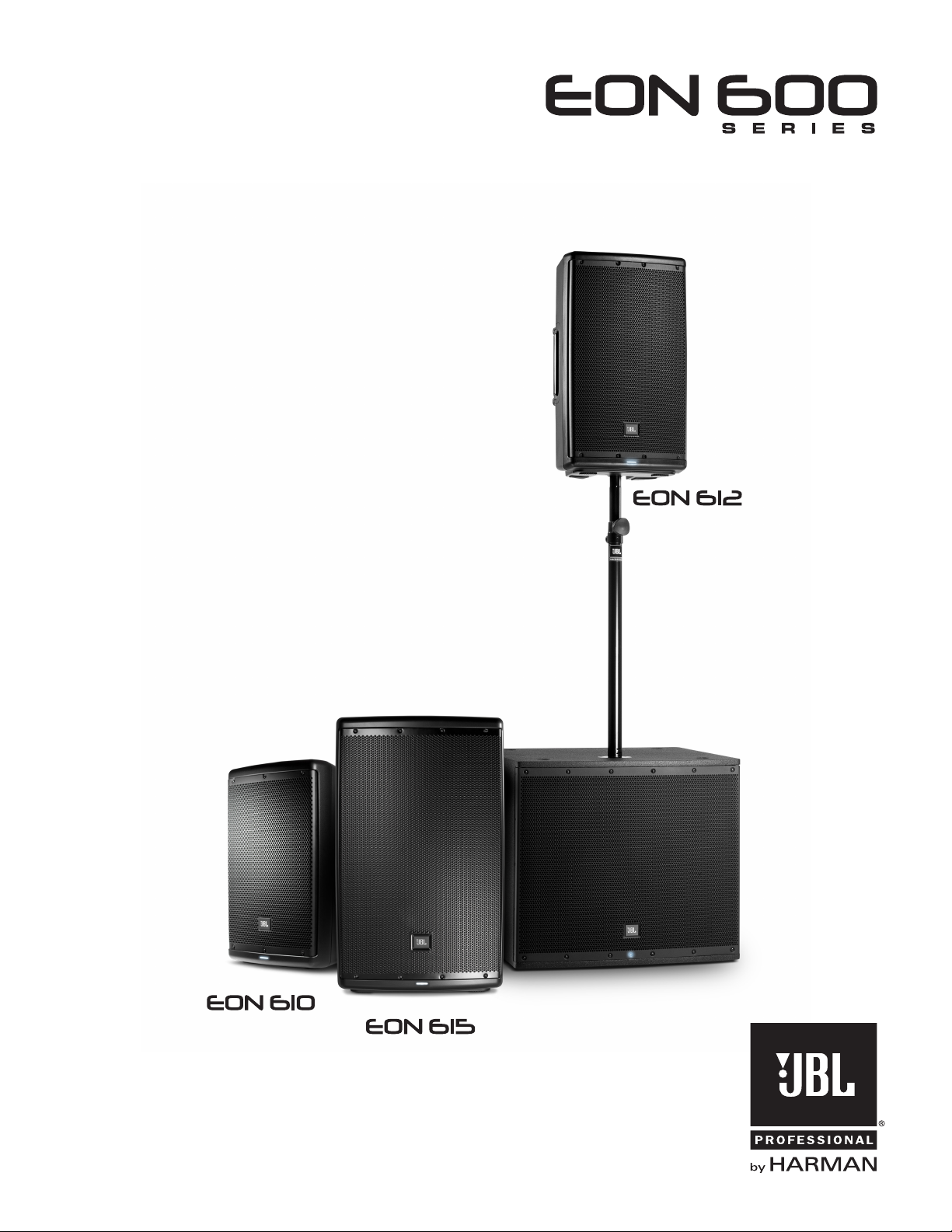
User’s Guide
EON 618S
Page 2

2
Page 3

CONTENTS
Safety Instructions .....................................................................................................................................4
Declaration Of Conformity ......................................................................................................................... 5
Quick Setup Guide ......................................................................................................................................6
Back Panel ..................................................................................................................................................8
Overview - EON Family .............................................................................................................................10
EON Family - Block Diagram ....................................................................................................................11
EON615 Specifications ............................................................................................................................13
EON612 Specifications ............................................................................................................................14
EON610 Specifications ............................................................................................................................15
EON618S Specifications ..........................................................................................................................16
Purposeful Product Design.......................................................................................................................17
Coverage .................................................................................................................................................. 18
Bluetooth Integration ................................................................................................................................19
Loudspeaker Placement and Suspension ...............................................................................................20
Application Examples .............................................................................................................................. 21
Trouble Shooting ....................................................................................................................................... 24
Warranty Information .............................................................................................................................. 25
Contact Information ................................................................................................................................. 26
3
Page 4

SAFETY INSTRUCTIONS
Before You Begin - Important Information
Before using your EON® speaker system please review the following for important
information on safety and protection of your investment in quality loudspeakers.
1. Read these instructions.
2. Keep these instructions.
3. Heed all warnings.
4. Follow all instructions.
5. Do not use this apparatus near water.
6. Clean only with dry cloth.
7. Do not block any ventilation openings. Install in accordance with the manufacturer’s instructions.
8. Do not install near any heat sources such as radiators, heat registers, stoves, or other apparatus
(including amplifiers) that produce heat.
9. Do not defeat the safety purpose of the polarized or grounding-type plug. A polarized plug has two blades with one wider than
the other. A grounding-type plug has two blades and a third grounding prong. The wide blade or the third prong is provided
for your safety. If the provided plug does not fit into your outlet, consult an electrician for replacement of the obsolete outlet.
10. Protect the power cord from being walked on or pinched, particularly at plugs, convenience receptacles, and the point where
they exit from the apparatus.
11. Only use attachments/accessories specified by the manufacturer.
12. Use only with the cart, stand, tripod, bracket, or table specified by the manufacturer, or sold with the
apparatus. When a cart is used, use caution when moving the cart/apparatus combination to avoid injury
from tip-over.
13. Unplug this apparatus during lightning storms or when unused for long periods of time.
14. Refer all servicing to qualified service personnel. Servicing is required when the apparatus has been
damaged in any way, such as power supply cord or plug is damaged, liquid has been spilled or objects
have fallen into the apparatus, the apparatus has been exposed to rain or moisture, does not operate normally,
or has been dropped.
15. Service Instruction in Owner’s Manual: “CAUTION - THESE SERVICING INSTRUCTIONS ARE FOR USE BY QUALIFIED SERVICE
PERSONNEL ONLY. TO REDUCE THE RISK OF ELECTRIC SHOCK DO NOT PERFORM ANY SERVICING OTHER THAN THAT
CONTAINED IN THE OPERATING INSTRUCTIONS UNLESS YOU ARE QUALIFIED TO DO SO.”
16. To completely disconnect this apparatus from the AC mains, disconnect the power supply cord plug from
the AC receptacle.
17. “WARNING – TO REDUCE THE RISK OF FIRE OR ELECTRIC – SHOCK, DO NOT EXPOSE THIS APPARATUS TO RAIN
OR MOISTURE.”
18. Do not expose this equipment to dripping or splashing and ensure that no objects filled with liquids, such as vases, are
placed on the equipment.
19. The mains plug of the power supply cord shall remain readily operable.
4
Page 5

DECLARATION OF CONFORMITY
Safety And EMC Compliance Specifications
EN 55103-1:1997 Electromagnetic Compatibility - Product Family Standard for Audio, Video, Audio-Visual and Entertainment Lighting Control
Apparatus for Professional Use, Part 1: Emissions
EN 55103-1:1997 Magnetic Field Emissions-Annex A@ 10 cm and 20 cm
EN 55022:2003 Limits and Methods of Measurement of Radio Disturbance Characteristics of ITE: Radiated, Class B Limits; Conducted, Class A
EN 55103-2:1997 Electromagnetic Compatibility - Product Family Standard for Audio, Video, Audio-Visual and Entertainment Lighting Control
Apparatus for Professional Use, Part 2: Immunity
EN 61000-4-2: A2:2001 Electrostatic Discharge Immunity (Environment E2-criteria B, 4 kV Contact, 8 kV Air discharge)
EN 61000-4-3:2003 Radiated, Radio-frequency, Electromagnetic Immunity (Environment E2, criteria A)
EN61000-4-4:2005 Electrical Fast Transient/Burst Immunity (criteria B)
EN 61000-4-5:2001 Surge Immunity (criteria B)
EN 61000-4-6:1996 Immunity to Conducted Disturbances Induced by Radio-Frequency Fields (criteria A)
EN 61000-4-11:2004 Voltage Dips, Short Interruptions and Voltage Variation
UL 6500 2nd Edition 1999 Audio/Video and Musical Instruments Apparatus for Household, Commercial, and Similar General Use
IEC 60065_2001 / EN 60065_2002 + A1:2006 + A11:2008
UL Compliance Specifications
UL 60065 7th Ed. CAN/CSA 22.2 No.60065_2003
FCC Statement IC Warning
1. This device complies with Part 15 of the FCC Rules.
Operation is subject to the following two conditions:
(1) This device may not cause harmful interference.
(2) This device must accept any interference received,
including interference that may cause undesired operation.
2. Changes or modifications not expressly approved by the party
responsible for compliance could void the user’s authority to
operate the equipment.
NOTE: This equipment has been tested and found to comply
with the limits for a Class B digital device, pursuant to Part 15 of
the FCC Rules. These limits are designed to provide reasonable
protection against harmful interference in a residential installation.
This equipment generates uses and can radiate radio frequency
energy and, if not installed and used in accordance with
the instructions, may cause harmful interference to radio
communications. However, there is no guarantee that interference
will not occur in a particular installation. If this equipment does
cause harmful interference to radio or television reception, which
can be determined by turning the equipment off and on, the user is
encouraged to try to correct the interference by one or more of the
following measures:
• Reorient or relocate the receiving antenna.
• Increase the separation between the equipment and receiver.
• Connect the equipment into an outlet on a circuit different from
that to which the receiver is connected.
• Consult the dealer or an experienced radio/TV technician for help.
1. This device complies with Industry Canada’s license-exempt RSSs.
Operation is subject to the following two conditions:
(1) this device may not cause interference, and
(2) this device must accept any interference, including interference
that may cause undesired operation of the device.
2. Changes or modifications not expressly approved by the party
responsible for compliance could void the user’s authority to operate
the equipment.
Le présent appareil est conforme aux CNR d’Industrie Canada applicables
aux appareils radio exempts de licence. L’exploitation est autorisée aux
deux conditions suivantes :
(1) l’appareil ne doit pas produire de brouillage, et
(2) l’utilisateur de l’appareil doit accepter tout brouillage
radioélectrique subi, même si le brouillage est susceptible d’en
compromettre le fonctionnement.”
FCC Radiation Exposure Statement
This equipment complies with FCC radiation exposure limits set forth for
an uncontrolled environment. This equipment should be installed and
operated with minimum distance 20cm between the radiator & your body
5
Page 6
QUICK SETUP GUIDE
Congratulations on your purchase of JBL Professional EON600 Series loudspeakers! We know you are anxious to get up and
running as fast as possible, which is why you are reading this section. The following will help you get set up as soon as possible.
Packaging Contents
Your EON600 system should include the following:
1 x EON600 speaker
1 x 10'(3m) IEC Power Cable
1 x Quick Start Guide
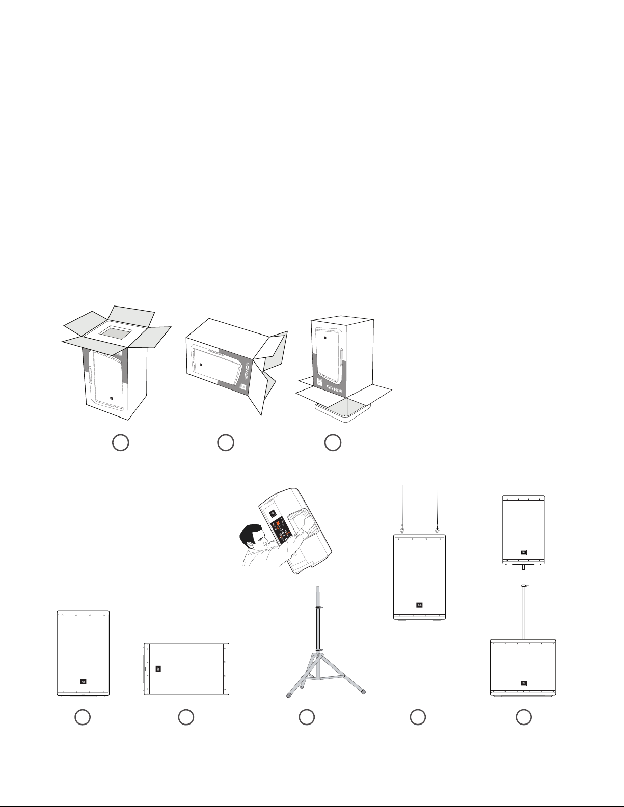
Unbox it
1
Open the top of the box. Turn box upside down, then lift box up to reveal speaker.Lay box on its side.
2
Configuration Options
1
2
3
3 4 5
Floor Standing Monitor Position Pole Mounted Suspended Subwoofer Mounted
6
Page 7
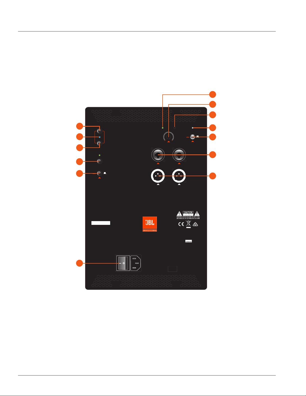
QUICK SETUP GUIDE
Bluetooth Sync
Bluetooth Boot
EQ Presets
Mic/Line Button
XLR-1/4” Combo Inputs
XLR Male Loop Thru
Power Switch
B
E
K
M
N
O
BLUETOOTH
SYNC
BOOT
EQ
F
PRESETS
MAIN
MONITOR
SUB
SPEECH
POWER
ON OFF
FRONT LED
EQ +
A
Power LED
D
Front LED On/Off
G
EQ+ On/Off
EON 615
H
CH1 & CH2 Gain
I
Limit LED
L
Master Volume
GAIN
MIC
LINE
MODEL: EON615
SERIAL NO:
THIS DEVICE COMPLIES WITH PART 15 OF THE FCC RULES.
OPERATION IS SUBJECT TO THE FOLLOWING TWO CONDITIONS:
(1) THIS DEVICE MAY NOT CAUSE HARMFUL INTERFERENCE.
(2) THIS DEVICE MUST ACCEPT ANY INTERFERENCE THAT MAY CAUSE UNDESIRED OPERATION.
430W Max
100-120VAC 50/60Hz
230-240VAC 50/60Hz
FUSE TYPE: T3.15L250V
FOR CONTINUED PROTECTION AGAINST RISK OF FIRE, REPLACE FUSE ONLY WITH SAME TYPE OF RATING.
MASTER
CH1 CH2
VOLUME
IN 1
THRU
LIMITSIGNAL SIGNAL
GAIN
IN 2
Made in
Mexico
JBL PROFESSIONAL
NORTHRIDGE, CA. USA
A HARMAN INTERNATIONAL COM PANY
DESIGNED AND ENGINEERED IN THE USA
MIC
LINE
POWER IT ON
1. Confirm the Power Switch ( O ) is in the OFF position.
2. Connect the supplied power cord to the power receptacle
on the rear of the speaker.
3. Connect the power cord to an available power outlet.
4. Flip on the Power Switch ( O ) and the Power LED ( A ) and
the Power LED on the front of the speaker will illuminate.
PLUG IN THE INPUTS
1. Turn Channel Gain Controls ( H ) and Master
Volume Control ( L ) all the way to the left before
connecting any inputs
2. Connect XLR or TRS cable from audio source to
CH1 or CH2 inputs ( M )
3. Select Mic or Line via the Mic/Line Button ( K;
Full-Range Only )
SET OUTPUT LEVEL
1. Using the EQ Preset ( F ) button, select the
appropriate preset to match your application ( FullRange Only ).
2. Set the gain level for the input using the Channel
Gain ( H ) controls. A good starting point is to set
the pot at 12 o’clock.
3. Slowly turn Master Volume ( L ) to the right until
the desired volume is reached.
7
Page 8
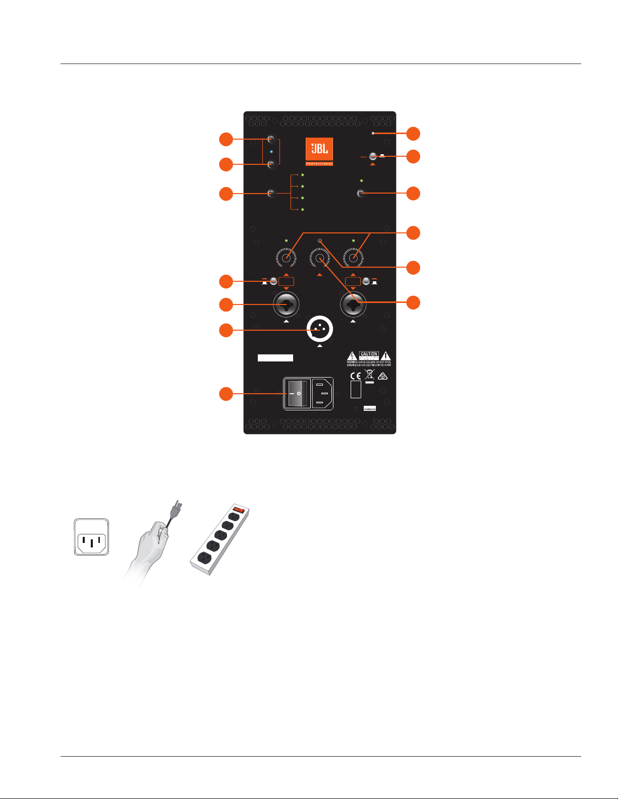
SUBWOOFER BACK PANEL
Bluetooth Sync
Bluetooth Indicator
Bluetooth Boot
EQ+ On/Off
Polarity Switch
B
C
E
G
P
BLUETOOTH
SYNC
BOOT
EQ +
0º180
POLARITY
º
LIMITSIGNAL
MASTER VOLUME
IN 1
THRU 1 THRU 2
IN 2
POWER
ON OFF
FRONT LED
J
Signal Indicator
L
Master Volume
I
Limit LED
A
Power LED
D
Front LED On/Off
M
XLR-1/4”Combo Inputs
N
XLR Male Loop Thru
Power Switch
MODEL: EON618S
SERIAL NO:
THIS DEVICE COMPLIES WITH PART 15 OF THE FCC RULES.
OPERATION IS SUBJECT TO THE FOLLOWING TWO CONDITIONS:
(1) THIS DEVICE MAY NOT CAUSE HARMFUL INTERFERENCE.
(2) THIS DEVICE MUST ACCEPT ANY INTERFERENCE THAT MAY CAUSE UNDESIRED OPERATION.
430W Max
100-120VAC 50/60Hz
230-240VAC 50/60Hz
FUSE TYPE: T3.15L250V
FOR CONTINUED PROTECTION AGAINST RISK OF FIRE, REPLACE FUSE ONLY WITH SAME TYPE OF RATING.
O
EON 618S
Made in
China
JBL PROFESSIONAL
NORTHRIDGE, CA. USA
A HARMAN INTERNATIONAL COMPANY
DESIGNED AND ENGINEERED IN THE USA
8
Page 9

BACK PANEL
A. Power LED
This LED (White) lights to indicate that the speaker is plugged in and
switched ON.
B. Bluetooth Sync
Depress this button in order to initiate pairing with your
Bluetooth enable device.
C. Bluetooth Indicator
This LED will illuminate blue to indicate that your Bluetooth
connection is established.
D. Front LED On/Off
Toggles the LED (Blue) on front of speaker On or Off.
E. Bluetooth Boot
Depress this button to reset the pairing with your Bluetooth enabled device
without having to turn the speaker off.
F. EQ Presets (Full-Range Only)
Use this button to toggle through the four different settings.
MAIN:
This is the default setting for the EON600 loudspeakers. Use this
setting when your EON600 loudspeaker is being used either on a
tripod or pole and facing towards your audience.
MONITOR:
Use this setting when your EON600 loudspeaker is being used as a
stage monitor facing towards you.
SUB:
Use this setting when your EON600 loudspeaker is being used in
conjunction with a separate subwoofer. This preset enables a High
Pass Filter (HPF) set at 100Hz.
SPEECH:
Use this setting when your EON600 loudspeaker is being used for
Speech only or Spoken Word only applications and is facing towards
the audience.
G. EQ+ Button
Once enabled via the app, the EQ+ toggles the applied EQ settings on/off.
H. CH1 & CH2 Gain (Full-Range Only)
Controls the gain of CH1 & CH2 respectively. By turning the signal counter-
clockwise you will be lowering the gain of your source material. By turning
the control clockwise you will be increasing the gain.
Limit Indicator
I.
The LIMIT LED (Red) illuminates to indicate that the system is approaching
limit. If this LED is on for more than the duration of brief dynamic peaks,
the system is being over-driven. Continuously over-driving the system will
result in unpleasant and fatiguing distortion and may lead to premature
failure of your speaker system.
J. Signal Indicators
The SIGNAL LEDs (Green) illuminates to indicate a usable signal is
present at connected INPUTS.
K. Mic/Line Toggle (Full-Range Only)
The MIC/LINE buttons selects between two sensitivity ranges. The buttons
are used to match the input sensitivity with the output level of the devices
connected to CH1 or CH2. Depressing the MIC/LINE switch selects
MIC (High Sensitivity).
CAUTION: Before adjusting this switch, be certain to rotate the control fully counter-clockwise.
After the MIC/LINE switch has been depressed, slowly rotate the control clock-wise until the
desired volume has been reached.
• Use the MIC position (depressed) when a microphone is
connected.
• Use the LINE position (disengaged) when a line level source
such as an audio mixing console, audio playback device or
electronic musical instrument is connected.
L. Master Volume
Controls the master volume of the unit. By turning the knob counter-
clockwise you will be lowering the overall volume of the speaker. By turning
the control clockwise you will be increasing the overall volume of the
speaker.
M. XLR-1/4” Combo Inputs
These balanced inputs accepts a standard XLR (female) connector and
also a 1/4” TRS phone plug. A broad range of signals from microphones,
audio mixing consoles and electronic musical instruments may be
connected here. The sensitivity of these inputs are controlled by the MIC/
LINE SWITCHES.
N. XLR Male Loop Thru
This XLR (male) output connector provides a method of sending audio
out to an external source. If signal is present on both inputs, the inputs will
be summed and sent out as a 50/50 mix
O. Power Switch
Enables the AC power to the unit on and off.
P. Polarity Switch (Subwoofer Only)
Switches the polarity of the subwoofer between 0 and 180 degrees. Useful
for correcting summing issues between the subwoofer and the top boxes.
Users should experiment with the switch at both positions and select the
best sounding option for their specific application.
9
Page 10

OVERVIEW - EON FAMILY
EON 618S
10" Two-way multipurpose
self-powered sound
reinforcement
• 1000 Watt
• 26 lbs. / 11.79 kg
• 110° H / 60° V Coverage
12" Two-way multipurpose
self-powered sound
reinforcement
• 1000 Watt
• 33 lbs. / 14.96 kg
• 100° H / 60° V Coverage
15" Two-way multipurpose
self-powered sound
reinforcement
• 1000 Watt
• 39 lbs. / 17.69 kg
• 90° H / 60° V Coverage
18” multipurpose powered
subwoofer
• 1000 Watt
• 78 lbs. / 35.3 kg
Thank you for purchasing the new JBL EON!
More than just another great JBL sound system, the new EON600 is a true step forward in technology developed specifically to
deliver the best sound possible regardless of its application. Completely rethinking how truly good an affordable self-contained,
portable PA system can be, JBL engineers purposely designed and built the EON600 from the ground up featuring JBL’s
advanced waveguide technology, JBL designed and manufactured transducers, and convenient, wireless remote control of its
onboard DSP EQ parameters via Bluetooth.
This total redesign of the EON platform leverages the latest technologies in cabinet materials, acoustic science, transducer
design and user friendliness that delivers the extraordinary quality of a high-end studio monitor in a fully professional, highly
flexible, easy to use, portable system for today’s working musicians and sound providers.
With proper care your EON Series speakers should provide you with many years of flawless performance, and are flexible
enough to be a part of your sound reinforcement system even as it grows in scope.
10
Page 11

THRU
HF
EON FAMILY - BLOCK DIAGRAM
LIMIT
LF
DSP
HPF
EQ+ EQ LIM
LPF
MAIN
MASTER
VOLUME
LEVEL 1
MONITOR
ON
SUB
SPEECH
OFF
LEVEL 2
SIGNAL
MIC
LINE
SIGNAL
CH1
CH2
MIC
LINE
EON 610, EON 612, and EON 615
11
Page 12

CH1
CH2
EON 618S - BLOCK DIAGRAM
LIMIT
DSP
EQ+EQLIM
80 Hz
100 Hz
ON
120 Hz
EON
OFF
SIGNAL
MASTER
VOLUME
LEVEL 1
MIC
LINE
SIGNAL
LEVEL 2
MIC
LINE
12
THRU
THRU
Page 13

380 mm
14.96 in
316 mm
12.44 in
664 mm
26.14 in
612
322 mm
12.67 in
295 mm
11.61 in
558 mm
21.97 in
610
EON615 SPECIFICATIONS
System Specification
System Type: Self powered 15”, two-way, bass-reflex
Maximum SPL Output: 127 dB
Frequency Range (-10 dB): 39 Hz - 20 kHz
Frequency Response (±3 dB): 50 Hz - 20 kHz
EQ: 3 Parametric EQ’s, High and Low Shelf (Available via Bluetooth app only)
Amplification
Amplifier Design: High Efficiency Class D
System Power Rating: 1000W Peak (700 LF + 300HF); 500W Continuous (350W LF + 150W HF)
Input Impedance: 20K ohms (Balanced)
Line Input Gain: Infinity to +26.8dB (+14dBu max input level)
Mic Input Gain: Infinity to +29dB (in addition to line input gain)
Connectors: 2 x Balanced XLR-1/4” combination inputs; 1 x male XLR loop thru out
LED Indicators: Power, Bluetooth, EQ Preset, EQ +, Signal CH1, Signal CH2, Limit
Cooling: Passively Cooled (No Fan)
AC Power Input: 100-120VAC 50/60Hz; 230-240VAC 50/60Hz
AC Power Consumption (120VAC): 1/8th Power – 1.14A (Max), 1/4th Power – 1.71A (Max), 1/3rd Power – 2.03A (Max)
Speaker Specification
LF Driver: 1 x JBL 615H 380mm (15”) woofer with 2” voice coil
HF Driver: 1 x JBL 2414H-1 25.4mm (1”) annular polymer diaphragm, neodymium compression driver
Coverage Pattern: 90º H x 60º V
Crossover Frequency: 1.8kHz
Enclosure
Material: Polypropylene, multi-purpose main & monitor
Suspension / Mounting: 36mm pole socket with stabilizing screw, 3 x M10 suspension points
Handles: One left, one right, one top, one bottom (4 total)
Finish: Black Granite
Grille: Powder coated perforated steel with acoustically transparent screen backing
Dimensions (H x W x D): 707mm x 439mm x 365mm (27.8” x 17.3” x 14.4”)
Gross Weight: 17.69 kg (39 lbs)
439 mm
17.3 in
707 mm
27.8 in
365 mm
14.4 in
Bottom View Front View Left View
Rear View
13
Page 14

EON612 SPECIFICATIONS
322 mm
12.67 in
295 mm
11.61 in
558 mm
21.97 in
610
System Specification
System Type: Self powered 12”, two-way, bass-reflex
Maximum SPL Output: 126 dB
Frequency Range (-10 dB): 48 Hz - 20 kHz
Frequency Response (±3 dB): 57 Hz - 20 kHz
EQ: 3 Parametric EQ’s, High and Low Shelf (Available via Bluetooth app only)
Amplification
Amplifier Design: High Efficiency Class D
System Power Rating: 1000W Peak (700 LF + 300HF); 500W Continuous (350W LF + 150W HF)
Input Impedance: 20K ohms (Balanced)
Line Input Gain: Infinity to +26.8dB (+14dBu max input level)
Mic Input Gain: Infinity to +29dB (in addition to line input gain)
Connectors: 2 x Balanced XLR-1/4” combination inputs; 1 x male XLR loop thru out
LED Indicators: Power, Bluetooth, EQ Preset, EQ +, Signal CH1, Signal CH2, Limit
Cooling: Passively Cooled (No Fan)
AC Power Input: 100-120VAC 50/60Hz; 230-240VAC 50/60Hz
AC Power Consumption (120VAC): 1/8th Power – 1.14A (Max), 1/4th Power – 1.71A (Max), 1/3rd Power – 2.03A (Max)
Speaker Specification
LF Driver: 1 x JBL 612H 380mm (12 in) woofer
HF Driver: 1 x JBL 2414H-1 25.4mm (1 in) polymer diaphragm, neodymium compression driver
Coverage Pattern: 100º H x 60º V nominal
Crossover Frequency: 1.8 kHz
Enclosure
Material: Polypropylene, multi-purpose main & monitor
Suspension / Mounting: 36mm pole socket with stabilizing screw, 3 x M10 suspension points
Handles: One left, one right, one top, one bottom (4 total)
Finish: Black Granite
Grille: Powder coated perforated steel with acoustically transparent screen backing
Dimensions (H x W x D): 664 mm x 380 mm x 316 mm (26.14“ x 14.96“ x 12.44“)
Gross Weight: 14.96 kg (33 lbs)
316 mm
12.44 in
664 mm
26.14 in
380 mm
14.96 in
14
Bottom View Front View Left View
Rear View
Page 15

EON610 SPECIFICATIONS
System Specification
System Type: Self powered 10”, two-way, bass-reflex
Maximum SPL Output: 124 dB
Frequency Range (-10 dB): 52 Hz -20 kHz
Frequency Response (±3 dB): 60 Hz - 20 kHz
EQ: 3 Parametric EQ’s, High and Low Shelf (Available via Bluetooth app only)
Amplification
Amplifier Design: High Efficiency Class D
System Power Rating: 1000W Peak (700 LF + 300HF); 500W Continuous (350W LF + 150W HF)
Input Impedance: 20K ohms (Balanced)
Line Input Gain: Infinity to +26.8dB (+14dBu max input level)
Mic Input Gain: Infinity to +29dB (in addition to line input gain)
Connectors: 2 x Balanced XLR-1/4” combination inputs; 1 x male XLR loop thru out
LED Indicators: Power, Bluetooth, EQ Preset, EQ +, Signal CH1, Signal CH2, Limit
Cooling: Passively Cooled (No Fan)
AC Power Input: 100-120VAC 50/60Hz; 230-240VAC 50/60Hz
AC Power Consumption (120VAC): 1/8th Power – 1.14A (Max), 1/4th Power – 1.71A (Max), 1/3rd Power – 2.03A (Max)
Speaker Specification
LF Driver: 1 x JBL 610H 322mm (10 in) woofer
HF Driver: 1 x JBL 2414H-1 25.4mm (1 in) polymer diaphragm, neodymium compression driver
Coverage Pattern: 110º H x 60º V nominal
Crossover Frequency: 1.8 kHz
Enclosure
Material: Polypropylene, multi-purpose main & monitor
Suspension / Mounting: 36mm pole socket with stabilizing screw, 3 x M10 suspension points
Handles: One left, one right, one top, one bottom (4 total)
Finish: Black Granite
Grille: Powder coated perforated steel with acoustically transparent screen backing
Dimensions (H x W x D): 558 mm x 322 mm x 295 mm (21.968“ x 12.677“ x 11.614“)
Gross Weight: 11.79 kg (26 lbs)
295 mm
11.61 in
558 mm
21.97 in
322 mm
12.67 in
Bottom View Front View Left View
Rear View
15
Page 16

EON618S SPECIFICATIONS
System Specification
System Type: Self powered 18”, subwoofer
Maximum SPL Output: 134 dB
Frequency Range (-10 dB): 31 Hz - 150Hz
Frequency Response (±3 dB): 42 Hz - 150Hz
EQ: 3 Parametric EQ’s, High and Low Shelf (Available via Bluetooth app only)
Amplification
Amplifier Design: High Efficiency Class D
System Power Rating: 1000W Peak, 500W Continuous
Input Impedance: 22K ohms (Balanced)
Line Input Gain: 0 + 36 dBu
Mic Input Gain: Connectors: 2 x Balanced XLR-1/4” combination inputs; 2 x male XLR loop thru out
LED Indicators: Front Power, Rear Power , Bluetooth, EQ+, Preset, Signal, Limit
Cooling: Passively Cooled (No Fan)
AC Power Input: 100-120VAC 50/60Hz; 230-240VAC 50/60Hz
AC Power Consumption (120VAC): 1/8th Power – 1.14A (Max), 1/4th Power – 1.71A (Max), 1/3rd Power – 2.03A (Max)
Speaker Specification
LF Driver: JBL 618H 457mm (18”) woofer with 2” voice coil
Crossover Frequency: Selectable; 80 Hz, 100 hz, or 120 Hz
Enclosure
Material: Duraflex coated wooden enclosure
Suspension / Mounting: M20 Threaded Pole Cup
Handles: 2
Finish: Black Duraflex
Grille: Powder coated perforated steel with acoustically transparent screen backing
Dimensions (H x W x D): 582mm x 668mm x 645mm (22.9” x 26.3” x 25.4”)
Gross Weight: 35.5 kg (78.2 lbs)
16
Bottom View Front View Left View
Rear View
Page 17

PURPOSEFUL PRODUCT DESIGN
Portability made easy
Enclosure designs have been optimized for ideal acoustic resonance taking advantage of injection molding techniques and
mechanical shaping of the enclosures. This results in tremendous increases in cabinet volumes which enable better acoustic
performance while maintaining the same footprint. Four intelligently positioned handles make the 600 easy to carry and move
around. Integrated hardware mounts, designed into the enclosures, allow each model to be flown when required. And indexed
feet molded into the enclosures allow for convenient storage and transport, secure stacking for stage monitor and traditional
stand up configurations, and unique acoustic configurations.
Pole Mount & Locking Feet Suspension Points Top Handle & Indexed Molding
Side Handle Secure Stacking Monitor Position
17
Page 18

COVERAGE
EON615
TYPICAL
EON612
TYPICAL
EON610
TYPICAL
EON600 Family Coverage Patterns Compared to a Typical Speaker
The EON600’s extraordinary performance results from a breakthrough approach to waveguide design. JBL engineers examined
the radiation characteristics of the EON’s high and low frequency drivers at 36 different points employing JBL’s exclusive, state
of the art measurement techniques, then designed individual waveguides for both components that control the sound radiation
at the high frequencies, the crossover point and at the low frequencies. Special fluting is designed into the structure that guides
the frequencies through the full range of the system. The result is consistent response throughout its 90 degree coverage
pattern. The quality and consistency between on axis and off axis response delivers uniform coverage and high intelligibility
throughout the coverage area, which means the EON600’s smooth, transparent sound is the same for the entire audience.
Coverage through Revolutionary Waveguides
Image Control Waveguide
Increased High Frequency detail. The Image Control
Waveguide’s patent-pending design precisely controls the
sound emanating from the EON600 in the vertical and
horizontal planes ensuring the representation of your mix is
neutral and accurate at the listening position.
Low Frequency Waveguide
JBL’s ground breaking new low frequency waveguide
features special fluting that is designed into the structure that
guides the frequencies through the full range of the system.
18
Page 19

BLUETOOTH INTEGRATION
iPad 8:35 PM
BACK
GUITAR : 01
SETUP
LEFT
OFFLINE
LOCATE
FRONT
Speaker Discovery
iPad 8:35 PM
20
TONE
12
100 50
6
0
-6
-12
-20
20 40 80 200 500 1K 2K 5K 10K 20K
TONE
BASS
DEMO
HOME
100
50
EON : 02
ONLINE
OFFLINE
LOCATE
BASS
FLAT
PEQ
SETTINGS INFO
SETTINGS INFO
GUITAR : 01
ON
20
12
6
PRESETS MENU
VOLUME
0
-6
-12
-20
Visit jblpro.com/EON600 to register
• Supports iOS & Android
RIGHT
• Bluetooth audio NOT supported
Features
• Bluetooth speaker discovery (up to 4 at one time)
• Bass and Treble control (Low and High Shelf EQ)
03
• PEQ + (3 parametric EQ filters with control over Frequency, Gain and Q)
• Master Volume control
• Recall back panel Factory Presets (Main, Monitor, Sub and Speech)
Bass & Treble Controls
iPad 8:35 PM
20
12
6
0
-6
-12
-20
20 40 80 200 500 1K 2K 5K 10K 20K
LOW
FREQ
MID
GAIN
HIGH
MID
500Hz
20dB
80Hz
LOW
12dB
Q
PEQ+ Controls
iPad 8:35 PM
20
12
6
0
-6
-12
-20
20 40 80 200 500 1K 2K 5K 10K 20K
LOW
FREQ
MID
GAIN
HIGH
MID
500Hz
CLOSE
GUITAR : 01
20
12
6
VOLUME
0
-6
-12
-20
20dB
80Hz
LOW
12dB
Q
• Save and Recall User EQ Presets
SETTINGS INFO
HOME
GUITAR : 01
HIGH
FLAT
BASIC
EQ
HIGH
03
FLAT
BASIC
EQ
ON
20
12
6
PRESETS MENU
VOLUME
0
-6
-12
-20
SETTINGS INFO
SPEAKER SELECTION
GUITAR : 01
OFFLINE OFFLINE
COPY SETTING
USER PRESETS
STEVE
02
03
04
SPEAKER FUNCTION SELECTION
MONITOR SUB
MAIN LIVE
03
EON : 02
SAVE
LOAD
SAVE
LOAD
SAVE
LOAD
SAVE
LOAD
5K
12dB
500Hz
20dB
10ct
HOME
ON
5K
12dB
500Hz
20dB
10ct
Preset Management
19
Page 20

LOUDSPEAKER PLACEMENT AND SUSPENSION
Suspended
Floor Monitor Floor Standing
The following guidelines will help you achieve optimum sound wherever you use your EON ® loudspeakers:
Tripod Stand
Stacking
Pole Mount
Only experienced professionals should attempt to suspend the speakers.
For permanent installation applications utilizing the M10 suspension points, JBL Professional recommends the use of three
(3) M10 x 1.5 thread pitch forged shoulder steel eyebolts with an 18-20mm threaded shaft, along with fender washers, rated
for overhead suspension. Users unfamiliar with safe rigging practices should not attempt to suspend loudspeakers. Please see
https://www.jblpro.com/pub/technote/tn_v1n14.pdf for more information.
Raise the speakers as high as possible.
For best results try to get the high frequency horn at least 2 to 4 feet above the heads of the audience. If the speakers are too
low, the people in the back of the audience will not receive the best quality sound.
Place the speakers between the microphones and the audience.
Feedback occurs when the microphones pick up sound from the speakers and “feed” the sound back through the sound
system. If space is limited, point the speakers away from the microphones to reduce feedback.
Locate the speakers away from turntables.
Low-frequency feedback occurs when the output of the speaker is picked up by the tone arm of the turntable and is reamplified. A heavy, solid turntable base and shock mounting can also reduce this type of feedback in DJ applications.
Use more speakers in large or highly reverberant spaces.
Spreading speakers throughout these spaces will produce much better sound than trying to compensate with loudness level or
equalization. For very long distances, the use of another set of speakers with time delay is recommended.
Stand speakers upright for PA - Tilt the speakers back on the side for stage monitoring. Upright stance provides even coverage
over a wide area. EON speakers are also designed with two slanted positions for stage monitoring applications.
20
Page 21

APPLICATION EXAMPLES
BLUETOOTH
SYNC
BOOT
MAIN
MONITOR
SUB
SPEECH
LIMITSIGNAL SIGNAL
GAIN
MASTER
CH1 CH2
VOLUME
MIC
LINE
EQ
PRESETS
IN 1
MODEL: EON615
SERIAL NO:
THIS DEVICE COMPLIES WITH PART 15 OF THE FCC RULES.
OPERATION IS SUBJECT TO THE FOLLOWING TWO CONDITIONS:
(1) THIS DEVICE MAY NOT CAUSE HARMFUL INTERFERENCE.
(2) THIS DEVICE MUST ACCEPT ANY INTERFERENCE THAT MAY CAUSE UNDESIRED OPERATION.
430W Max
100-120VAC 50/60Hz
230-240VAC 50/60Hz
FUSE TYPE: T3.15L250V
FOR CONTINUED PROTECTION AGAINST RISK OF FIRE, REPLACE FUSE ONLY WITH SAME TYPE OF RATING.
THRU
ON OFF
FRONT LED
EQ +
GAIN
IN 2
JBL PROFESSIONAL
NORTHRIDGE, CA. USA
A HARMAN INTERNATIONAL CO MPANY
DESIGNED AND ENGINEERED IN THE USA
POWER
Made in
Mexico
MIC
LINE
MIC
LINE
BLUETOOTH
SYNC
BOOT
EQ
PRESETS
MAIN
MONITOR
SUB
SPEECH
GAIN
MASTER
CH1 CH2
VOLUME
IN 1
LIMITSIGNAL SIGNAL
GAIN
IN 2
POWER
ON OFF
FRONT LED
EQ +
MIC
LINE
MODEL: EON615
SERIAL NO:
THIS DEVICE COMPLIES WITH PART 15 OF THE FCC RULES.
OPERATION IS SUBJECT TO THE FOLLOWING TWO CONDITIONS:
(1) THIS DEVICE MAY NOT CAUSE HARMFUL INTERFERENCE.
(2) THIS DEVICE MUST ACCEPT ANY INTERFERENCE THAT MAY CAUSE UNDESIRED OPERATION.
430W Max
100-120VAC 50/60Hz
230-240VAC 50/60Hz
FUSE TYPE: T3.15L250V
FOR CONTINUED PROTECTION AGAINST RISK OF FIRE, REPLACE FUSE ONLY WITH SAME TYPE OF RATING.
SMALL PA USING BOTH INPUTS AND THRU FUNCTION
CH1 input set to “Mic” CH2 input set to “Line”
EQ Preset: Main
THRU
Made in
Mexico
JBL PROFESSIONAL
NORTHRIDGE, CA. USA
A HARMAN INTERNATIONAL CO MPANY
DESIGNED AND ENGINEERED IN THE USA
21
Page 22

APPLICATION EXAMPLES
BLUETOOTH
SYNC
BOOT
MAIN
EQ
PRESETS
MIC
LINE
MONITOR
SUB
SPEECH
GAIN
MASTER
CH1 CH2
VOLUME
IN 1
MODEL: EON615
SERIAL NO:
THIS DEVICE COMPLIES WITH PART 15 OF THE FCC RULES.
OPERATION IS SUBJECT TO THE FOLLOWING TWO CONDITIONS:
(1) THIS DEVICE MAY NOT CAUSE HARMFUL INTERFERENCE.
(2) THIS DEVICE MUST ACCEPT ANY INTERFERENCE THAT MAY CAUSE UNDESIRED OPERATION.
430W Max
100-120VAC 50/60Hz
230-240VAC 50/60Hz
FUSE TYPE: T3.15L250V
FOR CONTINUED PROTECTION AGAINST RISK OF FIRE, REPLACE FUSE ONLY WITH SAME TYPE OF RATING.
LIMITSIGNAL SIGNAL
THRU
EQ +
GAIN
IN 2
JBL PROFESSIONAL
NORTHRIDGE, CA. USA
A HARMAN INTERNATIONAL COMPANY
DESIGNED AND ENGINEERED IN THE USA
POWER
ON OFF
FRONT LED
Made in
Mexico
EQ +
GAIN
IN 2
JBL PROFESSIONAL
NORTHRIDGE, CA. USA
A HARMAN INTERNATIONAL COMPANY
DESIGNED AND ENGINEERED IN THE USA
POWER
ON OFF
FRONT LED
Made in
Mexico
MIC
LINE
BLUETOOTH
SYNC
BOOT
MAIN
EQ
PRESETS
MIC
LINE
MIC
LINE
MONITOR
SUB
SPEECH
LIMITSIGNAL SIGNAL
GAIN
MASTER
CH1 CH2
VOLUME
IN 1
MODEL: EON615
SERIAL NO:
THIS DEVICE COMPLIES WITH PART 15 OF THE FCC RULES.
OPERATION IS SUBJECT TO THE FOLLOWING TWO CONDITIONS:
(1) THIS DEVICE MAY NOT CAUSE HARMFUL INTERFERENCE.
(2) THIS DEVICE MUST ACCEPT ANY INTERFERENCE THAT MAY CAUSE UNDESIRED OPERATION.
430W Max
100-120VAC 50/60Hz
230-240VAC 50/60Hz
FUSE TYPE: T3.15L250V
FOR CONTINUED PROTECTION AGAINST RISK OF FIRE, REPLACE FUSE ONLY WITH SAME TYPE OF RATING.
THRU
22
SMALL PA USING TWO SYSTEMS AS MONITORS
CH1 input set to “Mic” CH2 input set to “Line”
EQ Preset: Monitor
Page 23

APPLICATION EXAMPLES
BLUETOOTH
SYNC
BOOT
MAIN
EQ
PRESETS
MIC
LINE
MONITOR
SUB
SPEECH
GAIN
MASTER
CH1 CH2
VOLUME
IN 1
MODEL: EON615
SERIAL NO:
THIS DEVICE COMPLIES WITH PART 15 OF THE FCC RULES.
OPERATION IS SUBJECT TO THE FOLLOWING TWO CONDITIONS:
(1) THIS DEVICE MAY NOT CAUSE HARMFUL INTERFERENCE.
(2) THIS DEVICE MUST ACCEPT ANY INTERFERENCE THAT MAY CAUSE UNDESIRED OPERATION.
430W Max
100-120VAC 50/60Hz
230-240VAC 50/60Hz
FUSE TYPE: T3.15L250V
FOR CONTINUED PROTECTION AGAINST RISK OF FIRE, REPLACE FUSE ONLY WITH SAME TYPE OF RATING.
LIMITSIGNAL SIGNAL
THRU
BLUETOOTH
SYNC
BOOT
EQ +
GAIN
IN 2
JBL PROFESSIONAL
A HARMAN INTERNATIONAL COMPANY
DESIGNED AND ENGINEERED IN THE USA
POWER
ON OFF
FRONT LED
Made in
Mexico
NORTHRIDGE, CA. USA
ON OFF
FRONT LED
EQ +
GAIN
IN 2
JBL PROFESSIONAL
NORTHRIDGE, CA. USA
A HARMAN INTERNATIONAL COMPANY
DESIGNED AND ENGINEERED IN THE USA
Made in
POWER
Mexico
MIC
LINE
BLUETOOTH
SYNC
BOOT
MAIN
EQ
PRESETS
MIC
LINE
MIC
LINE
MONITOR
SUB
SPEECH
LIMITSIGNAL SIGNAL
GAIN
MASTER
CH1 CH2
VOLUME
IN 1
MODEL: EON615
SERIAL NO:
THIS DEVICE COMPLIES WITH PART 15 OF THE FCC RULES.
OPERATION IS SUBJECT TO THE FOLLOWING TWO CONDITIONS:
(1) THIS DEVICE MAY NOT CAUSE HARMFUL INTERFERENCE.
(2) THIS DEVICE MUST ACCEPT ANY INTERFERENCE THAT MAY CAUSE UNDESIRED OPERATION.
430W Max
100-120VAC 50/60Hz
230-240VAC 50/60Hz
FUSE TYPE: T3.15L250V
FOR CONTINUED PROTECTION AGAINST RISK OF FIRE, REPLACE FUSE ONLY WITH SAME TYPE OF RATING.
LIMITSIGNAL
MASTER VOLUME
POWER
ON OFF
FRONT LED
THRU
EQ +
º
0º180
POLARITY
MODEL: EON618S
SERIAL NO:
THIS DEVICE COMPLIES WITH PART 15 OF THE FCC RULES.
OPERATION IS SUBJECT TO THE FOLLOWING TWO CONDITIONS:
(1) THIS DEVICE MAY NOT CAUSE HARMFUL INTERFERENCE.
(2) THIS DEVICE MUST ACCEPT ANY INTERFERENCE THAT MAY CAUSE UNDESIRED OPERATION.
430W Max
100-120VAC 50/60Hz
230-240VAC 50/60Hz
FUSE TYPE: T3.15L250V
FOR CONTINUED PROTECTION AGAINST RISK OF FIRE, REPLACE FUSE ONLY WITH SAME TYPE OF RATING.
IN 1
THRU 1 THRU 2
EON 618S
IN 2
A HARMAN INTERNATIONAL COMPANY
DESIGNED AND ENGINEERED IN THE USA
JBL PROFESSIONAL
NORTHRIDGE, CA. USA
Made in
China
+
SMALL PA USING EXTERNAL MIXER
CH1 & CH2 Mic / Line inputs set to “Line”
EQ Preset: Sub (Full-Range)/EON (Subwoofer)
23
Page 24

TROUBLE SHOOTING
Symptom Likely Cause What to do
No sound
Speaker not connected
to active AC power
Power not switched on Switch on power and verify that power LED is on
Verify that speaker is connected and that the circuit is on
No sound, speaker is connected
to working AC power but won’t
come on.
No sound. Speaker comes on.
No sound with microphone
connected directly to the
MIC/ LINE input.
Signal sounds distorted and
very loud, PEAK light is lit
most of the time.
Signal sounds distorted even at
moderate volumes, LIMIT light
is not lit.
Lots of hiss in the sound,
the mixer controls are at
very low settings.
Noise or hiss heard at output. Noisy source device
Hum or Buzz that increases or
decreases when the mixer level
controls are moved.
Speaker power cable is faulty
or improperly connected.
Signal source
(mixer, instrument, etc.)
is not sending.
Faulty cables and
connections
Microphone requires
phantom power
Excessive input signal, trying
to exceed the capabilities of
the speakers
Mixer or other source
is overdriven
Improper gain structure
Improper A/C ground or
faulty equipment connected
to mixer input
Faulty cable between source
equipment and mixer
• Re-seat the power cable at both ends.
• Substitute a known-good power cable
• Check VU meters on the source mixer
• Verify that the tape or CD is playing.
• Use headphones to verify that the instrument is actually
sending an audio signal
• Disconnect and re-seat signal cables.
• Replace suspected cable with a known-good cable
The EON does not supply phantom power. Switch to a dynamic
microphone, use a battery powered microphone (if possible),
use an external phantom power supply for condenser type microphones.
• Reduce the output level of the source.
• Turn down the level controls on the speaker.
• Use additional EON speakers.
Review the Owner’s Manual for your mixer and adjust controls as needed.
• Input sensitivity (gain)
• Channel faders
• Master faders Once this is done, review the instructions in the Quick
Start section of this guide.
• Make sure that the MIC/LINE switch is in the LINE (disengaged) position.
• Reduce the level settings at speaker. Review the Owner’s Manual for
your mixer and adjust controls as needed.
• Input sensitivity (gain)
• Channel faders
• Master faders
Disconnect the devices that are connected to your speaker one at a time.
If the noise goes away, the problem is with the source or the
connecting cable.
Disconnect or mute channels one at a time to isolate the problem. Refer to
the owner’s manual of the faulty equipment for troubleshooting help.
Substitute a known-good cable for the suspected faulty cable.
24
Hum or Buzz
Improper A/C grounding,
ground loops
Excessively long
unbalanced cable run
Improper system gain
structure
• ‘Lift’ the audio ground by using an XLR/F to XLR/M adapter on one end.
• Re-route audio cables away from AC power and lighting cables.
• Use the balanced outputs (if available) of your mixer or source
equipment to drive your EON speakers.
• Use a “DI” (direct injection) box to convert your unbalanced equipment
output to a balanced output.
Reduce the INPUT level controls and increase the output level of your
source devices.
Page 25

WARRANTY INFORMATION
The JBL Limited Warranty on professional loudspeaker products (except for enclosures) remains in effect for five years from the
date of the first consumer purchase. JBL amplifiers are warranted for three years from thedate of original purchase. Enclosures
and all other JBL products are warranted for two years from the date of original purchase.
Who Is Protected By This Warranty?
Your JBL Warranty protects the original owner and all subsequent owners so long as: A.) Your JBL product has been purchased
in the Continental United States, Hawaii or Alaska. (This Warranty does not apply to JBL products purchased elsewhere except
for purchases by military outlets. Other purchasers should contact the local JBL distributor for warranty information.); and B.)
The original dated bill of sale is presented whenever warranty service is required.
What Does The JBL Warranty Cover?
Except as specified below, your JBL Warranty covers all defects in material and workmanship. The following are not covered:
Damage caused by accident, misuse, abuse, product modification or neglect; damage occurring during shipment; damage
resulting from failure to follow instructions contained in your Instruction Manual; damage resulting from the performance of
repairs by someone not authorized by JBL; claims based upon any misrepresentations by the seller; any JBL product on which
the serial number has been defaced, modified or removed.
Who Pays For What?
JBL will pay all labor and material expenses for all repairs covered by this warranty. Please be sure to save the original shipping
cartons because a charge will be made if replacement cartons are requested. Payment of shipping charges is discussed in the
next section of this warranty.
How To Obtain Warranty Performance
If your JBL product ever needs service, write or telephone us at JBL Incorporated (Attn: Customer Service Department), 8500
Balboa Boulevard, PO. Box 2200, Northridge, California 91329 (818/893-8411). We may direct you to an authorized JBL
Service Agency or ask you to send your unit to the factory for repair. Either way, you’ll need to present the original bill of sale to
establish the date of purchase. Please do not ship your JBL product to the factory without prior authorization. If transportation
of your JBL product presents any unusual difficulties, please advise us and we may make special arrangements with you.
Otherwise, you are responsible for transporting your product for repair or arranging for its transportation and for payment of any
initial shipping charges. However, we will pay the return shipping charges if repairs are covered by the warranty.
Limitation of Implied Warranties
ALL IMPLIED WARRANTIES, INCLUDING WARRANTIES OF MERCHANTABILITY AND FITNESS FOR PARTICULAR PURPOSE, ARE
LIMITED IN DURATION TO THE LENGTH OF THIS WARRANTY.
EXCLUSION OF CERTAIN DAMAGES
JBL’S LIABILITY IS LIMITED TO THE REPAIR OR REPLACEMENT, AT OUR OPTION, OF ANY DEFECTIVE PRODUCT AND SHALL
NOT INCLUDE INCIDENTAL OR CONSEQUENTIAL DAMAGES OF ANY KIND. SOME STATES DO NOT ALLOW LIMITATIONS ON
HOW LONG AN IMPLIED WARRANTY LASTS AND/OR DO NOT ALLOW THE EXCLUSION OF INCIDENTAL OR CONSEQUENTIAL
DAMAGES, SO THE ABOVE LIMITATIONS AND EXCLUSIONS MAY NOT APPLY TO YOU. THIS WARRANTY GIVES YOU SPECIFIC
LEGAL RIGHTS, AND YOU MAY ALSO HAVE OTHER RIGHTS, WHICH VARY, FROM STATE TO STATE.
JBL Professional
8500 Balboa Blvd. Northridge, CA 91329 USA
25
Page 26

CONTACT INFORMATION
Mailing Address:
JBL Professional
8500 Balboa Blvd.
Northridge, CA 91329
Shipping Address:
JBL Professional
8500 Balboa Blvd., Dock 15
Northridge, CA 91329
(Do not return product to this address without first obtaining prior authorization from JBL)
Customer Service:
Monday through Friday
8:00am -5:00pm
Pacific Coast Time in the U.S.A.
(800) 8JBLPRO (800.852.5776)
www.jblproservice.com
On The World Wide Web:
www.jblpro.com
Professional Contacts, Outside the USA:
Contact the JBL Professional Distributor in your area.
A complete list of JBL Professional international distributors is provided at our U.S.A. website: www.jblpro.com
26
Page 27

27
Page 28

Part Number: 5032132 8/15 8500 Balboa Boulevard Northridge, CA 91329 USA www.jblpro.com
 Loading...