

Page 1
Instruction Book
AirThread 2000D Professional
Janome 2000D Air Threading Serger Owners Manual
Janome Air Thread Instruction Book
Page 2

IMPORTANT SAFETY INSTRUCTIONS
When using an electrical appliance, basic safety precautions should always be followed, including the
following:
This Serger/Overlocker/Overlock machine is designed and manufactured for household use only.
Read all instructions before using this Serger/Overlocker/Overlock machine.
DANGER
—
To reduce the risk of electric shock:
1. An appliance should never be left unattended when plugged in. Always unplug
this Serger/Overlocker/Overlock machine from the electric outlet immediately after
using and before cleaning.
WARNING
—
To reduce the risk of burns, fire, electric shock, or injury to persons:
1. Do not allow to be used as a toy. Close attention is necessary when this Serger/Overlocker/Overlock
machine is used by or near children.
2. Use this appliance only for its intended use as described in this owner’s manual.
Use only attachments recommended by the manufacturer as contained in this owner’s manual.
3. Never operate this Serger/Overlocker/Overlock machine if it has a damaged cord or plug, if it is not
working properly, if it has been dropped or damaged, or dropped into water.
Return this Serger/Overlocker/Overlock machine to the nearest authorized dealer or service center
for examination, repair, electrical or mechanical adjustment.
4. Never operate the appliance with any air opening blocked. Keep ventilation openings of this
Serger/Overlocker/Overlock machine and foot controller free from accumulation of lint, dust and
loose cloth.
5. Never drop or insert any object into any opening.
6. Do not use outdoors.
7. Do not operate where aerosol (spray) products are being used or where oxygen is being
administered.
8. To disconnect, turn all controls to the off (“O”) position, then remove plug from outlet.
9. Do not unplug by pulling on cord. To unplug, grasp the plug, not the cord.
10. Keep fingers away from all moving parts. Special care is required around the Serger/Overlocker/
Overlock machine needle and/or cutting blade.
11. Always use the proper needle plate. The wrong plate can cause the needle to break.
12. Do not use bent needles.
13. Do not pull or push fabric while stitching. It may deflect the needle causing it to break.
14. Switch this Serger/Overlocker/Overlock machine off (“O”) when making any adjustment in the
needle area, such as threading the needle, changing the needle or changing the presser foot, and
the like.
15. Always unplug this Serger/Overlocker/Overlock machine from the electrical outlet when removing
covers, lubricating, or when making any other adjustments mentioned in this owner’s manual.
SAVE THESE INSTRUCTIONS
Please note that on disposal, this product must be safely recycled in accordance with relevant
National legislation relating to electrical/electronic products. If in doubt please contact your
retailer for guidance. (European Union only)
For Europe only:
This appliance can be used by children aged from 8 years and above and persons with reduced
physical, sensory or mental capabilities or lack of experience and knowledge if they have been given
supervision or instruction concerning use of the appliance in a safe way and understand the hazards
involved. Children shall not play with the appliance. Cleaning and user maintenance shall not be made
by children without supervision.
For outside Europe (except U.S.A and Canada):
This appliance is not intended for use by persons (including children) with reduced physical, sensory or
mental capabilities, or lack of experience and knowledge, unless they have been given supervision or
instruction concerning use of the appliance by a person responsible for their safety.
Children should be supervised to ensure that they do not play with the appliance.
1
Page 3

2
ESSENTIAL PARTS
Names of Parts............................................................... 3
Safety Device ................................................................. 4
Standard Accessories .................................................... 5
Waste Chip Box.............................................................. 6
GETTING READY TO SEW
Connecting the Power Supply ........................................ 7
Before Using Your Machine............................................ 7
Operating Instructions: ................................................... 7
Controlling Sewing Speed .............................................. 7
Handwheel ..................................................................... 8
Looper Cover.................................................................. 8
Side Cover...................................................................... 8
Presser Foot Lifter.......................................................... 9
Removing or Attaching the Presser Foot ....................... 9
Presser Foot Guide Lines............................................... 9
Presser Foot Pressure Dial .......................................... 10
Changing the Needle.................................................... 10
Checking the needle .................................................. 10
Stitch Length Adjustment ..............................................11
Differential Feed Ratio Adjustment ..............................11
How to adjust...............................................................11
Gathering.....................................................................11
To Deactivate or Activate the Upper Knife ................... 12
Cutting Width Adjustment............................................. 12
Chaining Finger Switch Knob Adjustment (Changing to
Standard Serging or Rolled Hemming) ........................ 13
Standard serging ........................................................ 13
Rolled hemming ......................................................... 13
Position of Thread Guide Bar ....................................... 14
Attaching the Spool Holder Cap and Net ..................... 14
MACHINE THREADING
Threading the Machine (4 threads) .............................. 15
Preparation................................................................. 15
Lower looper pre-tension setting slider ...................... 15
Threading the Machine (3 threads) .............................. 16
Threading the Machine (2 threads) .............................. 17
Using the Spreader for Two-thread Serging................. 18
Raising the spreader .................................................. 18
Lowering the spreader................................................ 18
Threading the Lower Looper ................................... 19-21
Threading the Upper Looper ................................... 22-25
Adjusting the looper threader switch lever ................... 23
Threading Loopers with the Looper Threading Wire or
Standard Thread ..................................................... 26-27
Using the looper threading wire ................................. 26
Using a standard thread ............................................. 27
Replacing threaded looper thread.............................. 27
Threading the Right Needle ....................................28-30
Using the needle threader .......................................... 30
Threading the Left Needle....................................... 31-32
Thread and Needle Chart............................................. 33
TEST STITCHING
Starting Sewing ............................................................ 34
Finishing Sewing .......................................................... 34
Sewing Continuously.................................................... 35
Using Guide Lines ........................................................ 35
Securing Ends .............................................................. 36
At the beginning of the seam...................................... 36
At the end of the seam ............................................... 36
Cutting the Seams........................................................ 36
Thread Tension (4 threads) .......................................... 37
TABLE OF CONTENTS
Thread Tension (3 threads) .......................................... 39
Thread Tension (2 threads) .......................................... 40
ROLLED HEMMING, PICOT EDGING AND NARROW
HEMMING
Tension Dial and Machine Settings According to the
Thread and Fabric ........................................................ 42
For Better Results ........................................................ 43
Thread Tension........................................................44-45
ADVANCED TECHNIQUES
Decorative Overedging................................................. 46
Gathering...................................................................... 47
Pintucking..................................................................... 48
Flatlock ....................................................................49-50
Sewing Corners............................................................ 51
CARE OF YOUR MACHINE
Cleaning the Upper Knife Area .................................... 52
Cleaning the Feed Dog ................................................ 52
Cleaning the Lo oper Threader Pipe ............................. 53
Replacing the Upper Knife ........................................... 54
Oiling the Machine........................................................ 55
Troubleshooting............................................................ 56
Optional Accessories ................................................... 57
EC DECLARATION OF CONFORMITY ....................... 58
Page 4
NOTE:
Serger/Overlocker/Overlock machine design and
specifications are subject to change without prior
notice.
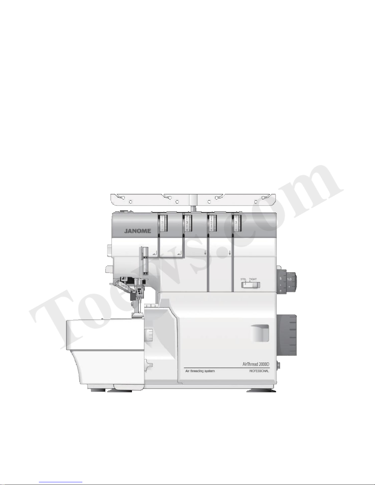
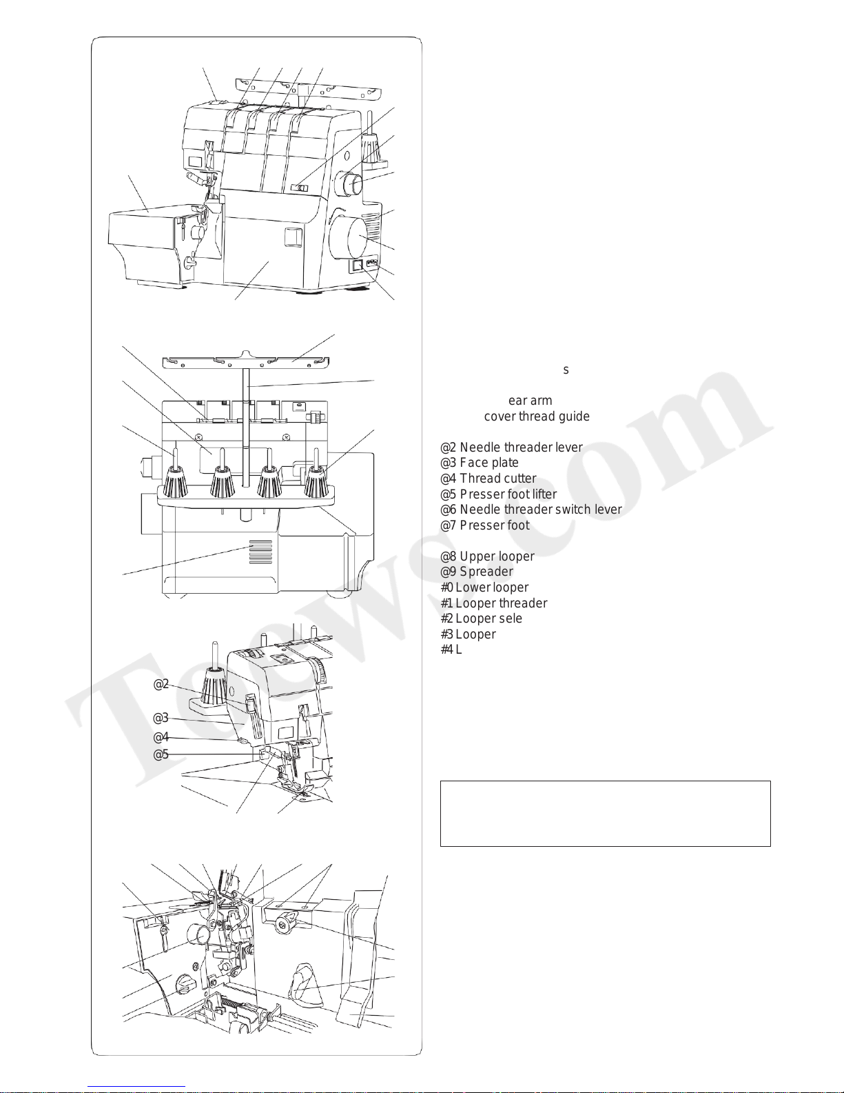
ESSENTIAL PARTS
Names of Parts
q Left needle thread tension dial
w Right needle thread tension dial
e Upper looper thread tension dial
r Lower looper thread tension dial
t Lower looper pre-tension setting slider
y Stitch length dial
u Differential feed dial
i Ventilation openings
o Handwheel
!0 Machine socket
!1 Power switch
!2 Looper cover
!3 Side cover
!4 Presser foot pressure dial
!5 Thread guide
!6 Thread guide bar
!7 Spool holder
!8 Ventilation openings
!9 Spool pin
@0 Hole of rear arm
@1 Top cover thread guide
@2 Needle threader lever
@3 Face plate
@4 Thread cutter
@5 Presser foot lifter
@6 Needle threader switch lever
@7 Presser foot
@8 Upper looper
@9 Spreader
#0 Lower looper
#1 Looper threader hole
#2 Looper selection lever
#3 Looper threader switch lever
#4 Looper threader lever
#5 Upper knife release knob
#6 Looper cover guide
#7 Cutting width adjusting dial
#8 Chaining finger switch knob
#9 Lower knife
$0 Upper knife
$1 Chaining finger
@2
@3
@4
@5
@6
@7
q w e r
t
y
u
i
o
!0
!1
!2
!3
!4
!5
!6
!7
!8
!9
@0
@1
#0
#1
#2
#3
#4
#6
#5
#7
#8
@8
@9
#99
$0
$1
3
Page 5
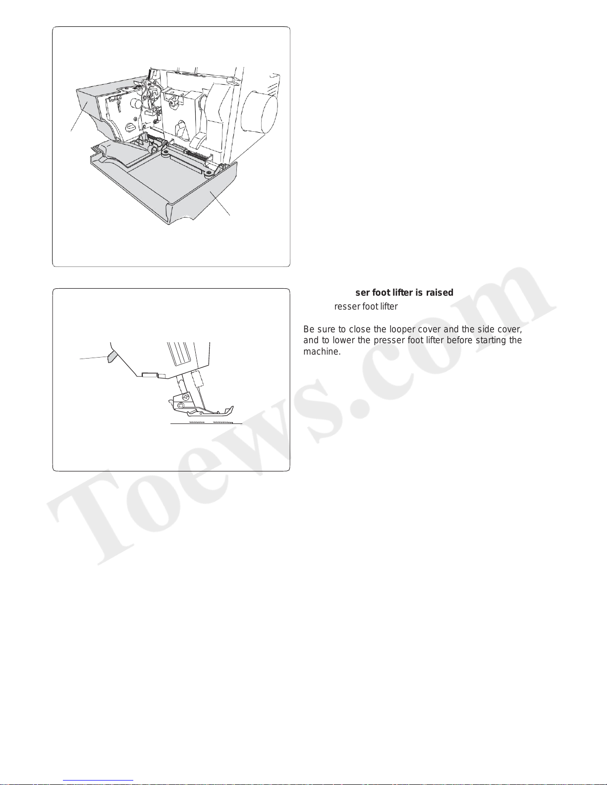
Safety Device
This machine is equipped with a safety device that
prevents the machine from starting in the following
conditions:
• The looper cover or the side cover is open
q Looper cover
w Side cover
q
4
w
e
• The presser foot lifter is raised
e Presser foot lifter
Be sure to close the looper cover and the side cover,
and to lower the presser foot lifter before starting the
machine.
Page 6

q w
e
r
t y
u
i
o
!
0
!
1
!
2
!
3
!
4
!
5
!
6
!
7
!
8
Standard Accessories
5
*The foot control included may differ from the illustration.
No.
Part Name
Part No.
1
Screwdriver (large)
784810002
2
Screwdriver (small)
647803004
3
Double-ended spanner
799807002
4
Tweezers
624801001
5
Needle set
(HAx1 SP#11) x 2
(HAx1 SP#14) x 3
784860100
6
Net
624806006
7
Spool holder cap (Large)
822020503
8
Lint brush
802424004
9
Oil
741814003
10
Needle holder/spreader pin
799802007
11
Upper knife
799096000
12
Looper threading wire (Looper
threader)
799803008
13
Accessory box
366401400
14
Waste chip box
799801006
15
Instruction manual
799800005
16
Instructional DVD
799804009
17
Cover
797608005
18
Foot control*
U.S.A and Canada
C-1028
U.K.
C-2085-1
Australia
C-2065
Continental Europe
C-2060
Page 7
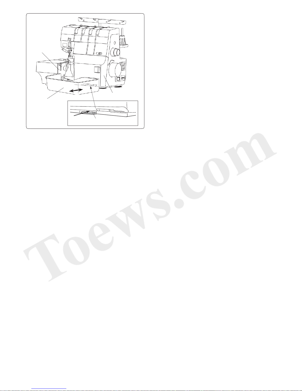
Waste Chip Box
The waste chip box collects trimmings.
Dispose trimmings after sewing.
To attach:
Sliding the waste chip box along the looper cover guide,
insert the tabs into the slit under the looper cover.
q Looper cover
w Waste chip box
e Looper cover guide
r Slit
To remove:
Pull the waste chip box toward you.
6
q
w
e
r
Page 8
GETTING READY TO SEW
Connecting the Power Supply
WARNING
While in operation, always keep your eyes on the
sewing area, and do not touch any moving parts
such as the thread take-up lever, handwheel, knives,
loopers or needles.
Always turn off the power switch and unplug the
machine from the power supply:
- when leaving the machine unattended.
- when attaching or removing parts.
- when cleaning the machine.
Do not place anything on the foot control.
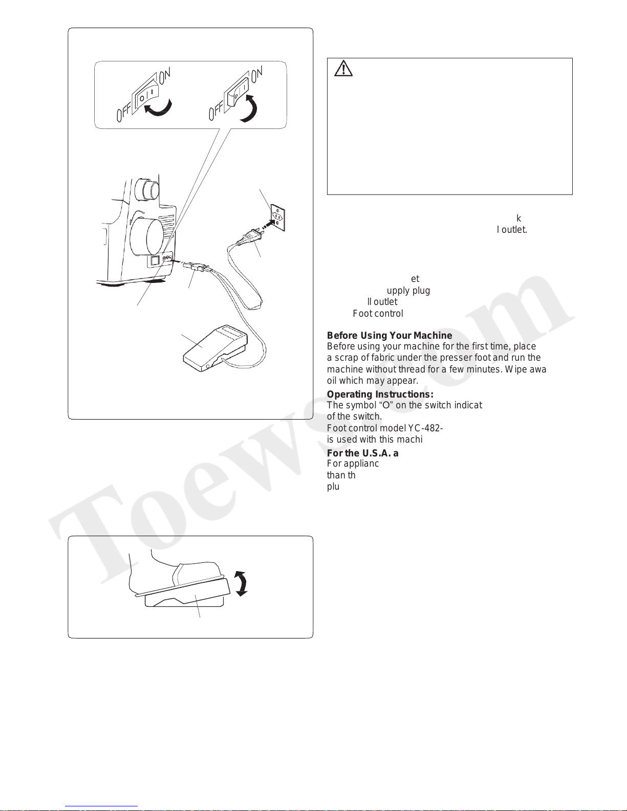
Turn the power switch off.
Insert the machine plug into the machine socket.
Insert the power supply plug into the wall outlet.
Turn the power switch on.
q Power switch
w Machine plug
e Machine socket
r Power supply plug
t Wall outlet
y Foot control
Before Using Your Machine
Before using your machine for the first time, place
a scrap of fabric under the presser foot and run the
machine without thread for a few minutes. Wipe away any
oil which may appear.
Operating Instructions:
The symbol “O” on the switch indicates the “off” position
of the switch.
Foot control model YC-482-J-1 (U.S.A and Canada only)
is used with this machine.
For the U.S.A. and Canada only:
For appliances with a polarized plug (one blade wider
than the other): To reduce the risk of electric shock, this
plug is intended to fit in a polarized outlet only one way. If
it still does not fit, contact a qualified electrician to install
the proper outlet. Do not modify the plug in any way.
Controlling Sewing Speed
Depress the foot control to start the machine.
The further down you press on the foot control, the faster
the machine runs.
q Foot control
q
q
t
r
w
e
y
7
Page 9
Handwheel
Match the “ ” mark of the belt cover with the “–” mark
of the handwheel when threading needles, adjusting
the chaining finger switch knob or raising/lowering the
spreader.
Always turn the handwheel toward you
(counterclockwise).
q Handwheel
w Belt cover
e “ ” mark
r “–” mark
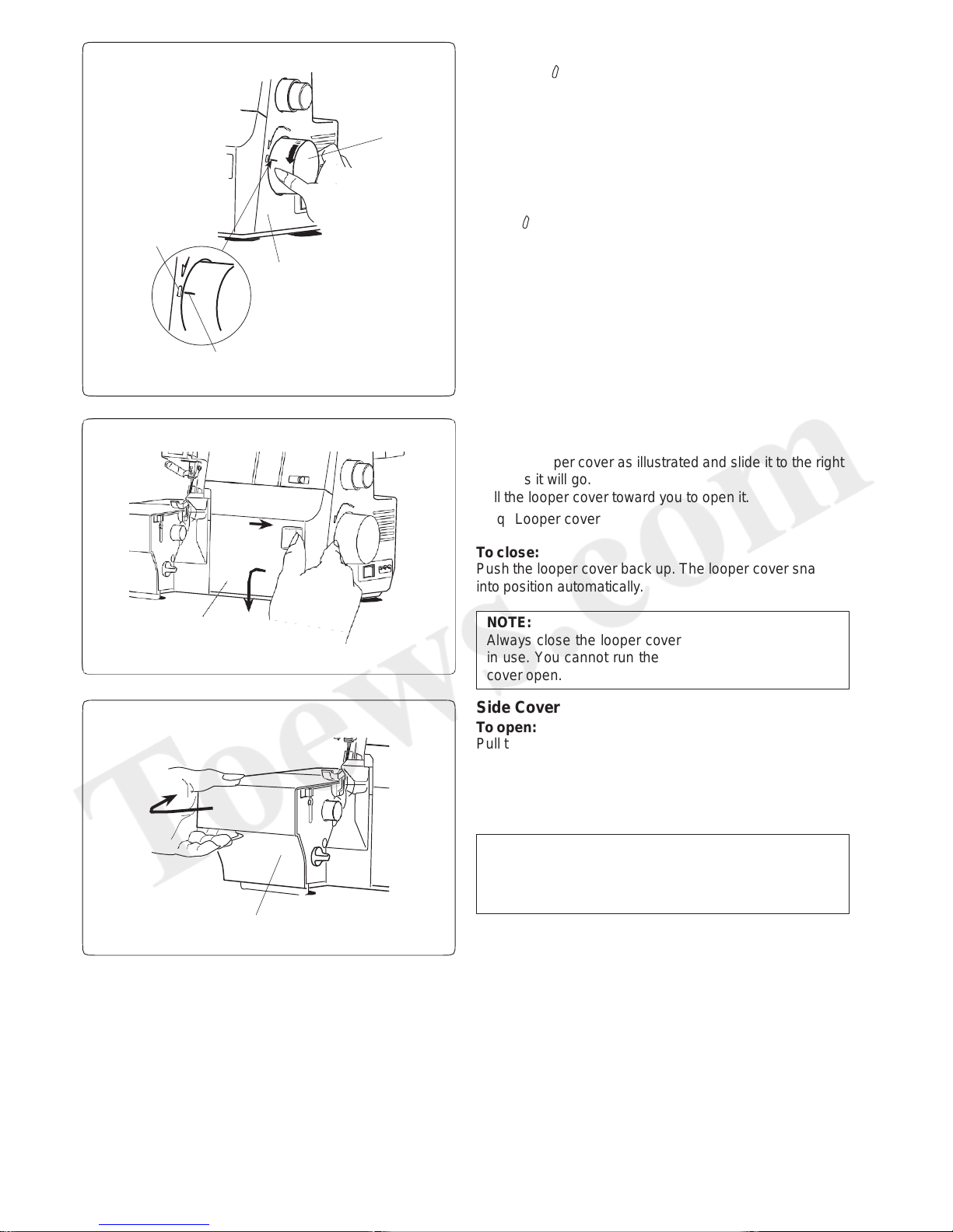
Looper Cover
To open:
Hold the looper cover as illustrated and slide it to the right
as far as it will go.
Pull the looper cover toward you to open it.
q Looper cover
To close:
Push the looper cover back up. The looper cover snaps
into position automatically.
Side Cover
To open:
Pull the side cover to the left.
q Side cover
To close:
Push the side cover to the right.
q
q
q
e
w
r
NOTE:
Always close the looper cover when the machine is
in use. You cannot run the machine with the looper
cover open.
NOTE:
Always close the side cover when the machine is in
use. You cannot run the machine with the side cover
open.
8
Page 10
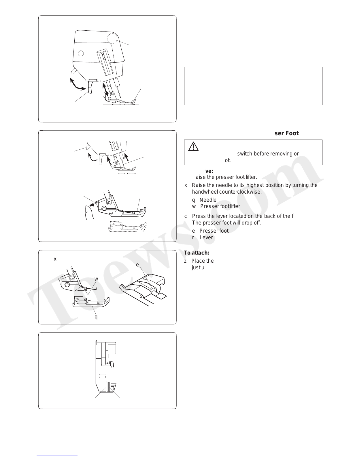
Removing or Attaching the Presser Foot
CAUTION:
Turn OFF the power switch before removing or
attaching the foot.
To remove:
z Raise the presser foot lifter.
x Raise the needle to its highest position by turning the
handwheel counterclockwise.
q Needle
w Presser foot lifter
c Press the lever located on the back of the foot holder.
The presser foot will drop off.
e Presser foot
r Lever
To attach:
z Place the presser foot so that the pin on the foot is
just under the groove on the foot holder.
Lower the foot holder to lock the foot into place.
x Raise the presser foot lifter.
Make sure that the presser foot is secured.
q Presser foot
w Groove
e Pin
Presser Foot Guide Lines
The guide lines on the toe of the presser foot are marked
with two needle positions.
The left guide line is marked at the left needle position.
The right guide line is marked at the right needle position.
q Left needle position
w Right needle position
z x
z x
c
q
w
e
r
q
q
w
w
e
e
q
w
Presser Foot Lifter
The presser foot lifter raises and lowers the presser foot.
Raise the presser foot lifter before you thread the
machine.
Always lower the presser foot lifer when you start sewing.
q Presser foot
w Presser foot lifter
9
NOTE:
Tension disks open when the presser foot lifter is
raised. Raise presser foot lifter when you pass the
thread between the tension disks.
e Presser foot lifter
Page 11
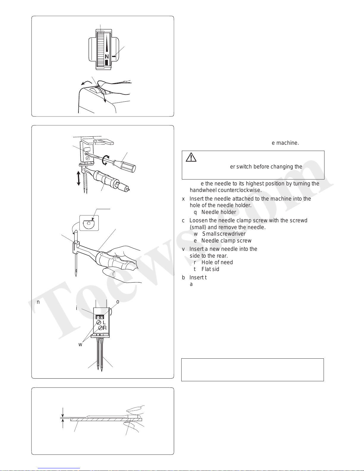
CAUTION
Turn OFF the power switch before changing the
needle.
z Raise the needle to its highest position by turning the
handwheel counterclockwise.
x Insert the needle attached to the machine into the
hole of the needle holder.
q Needle holder
c Loosen the needle clamp screw with the screwdriver
(small) and remove the needle.
w Small screwdriver
e Needle clamp screw
v Insert a new needle into the needle holder with the flat
side to the rear.
r Hole of needle holder
t Flat side
b Insert the needle into the needle clamp and push it up
as far as it will go.
n The top of the right needle should touches the bottom
of the needle bar and the top of the left needle should
touches the edge of the needle bar.
y Left needle
u Right needle
i Edge of needle bar
o Bottom of needle bar
m Firmly tighten the needle clamp screw with the
screwdriver (small) while holding the holder in place.
Pull the needle holder down to remove the needle.
Checking the needle
To see if the needle is in good condition, place the flat
side of the needle onto something flat (needle plate, glass
etc.). The gap between the needle and the flat surface
should be consistent. Never use a bent or blunt needle.
q Flat side
w Something flat
e Gap
Changing the Needle
* Use an HA-1 SP #14 or #11 needle.
* An HA-1 SP #14 needle is set on the machine.
q
w
e
q
w
q
e
r
y
u
i
o
w
e
w
q
r
10
t
q
x c b m
n
Presser Foot Pressure Dial
Foot pressure can be adjusted by turning the presser foot
pressure dial.
Set the pressure to “N” for ordinary fabrics.
Turn the dial toward you for light weight fabrics .
Turn the dial away from you for heavy weight fabrics.
q Presser foot pressure dial
w Setting mark
e To increase
r To decrease
You do not need to adjust the presser foot pressure for
normal sewng.
After making an adjustment, sew and check the pressure.
v
NOTE:
Partially tighten the needle clamp screw on the side
that is not being used to prevent losing the screw.
Page 12
Stitch Length Adjustment
To adjust the stitch length, turn the stitch length dial.
The larger the number, the longer the stitch.
q Stitch length dial
w Setting mark
The standard stitch length setting for serging stitch is “3”
(approximately 3 mm).
The dial clicks when you turn the dial to 3.
The stitch length can be adjusted while sewing.
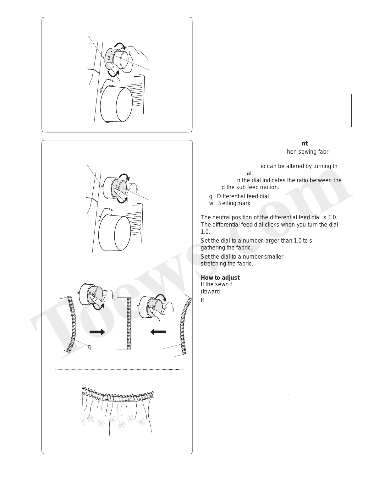
Differential Feed Ratio Adjustment
Adjust the differential feed ratio when sewing fabrics that
tend to stretch or pucker.
The differential feed ratio can be altered by turning the
differential feed dial.
The number on the dial indicates the ratio between the
main and the sub feed motion.
q Differential feed dial
w Setting mark
The neutral position of the differential feed dial is 1.0.
The differential feed dial clicks when you turn the dial at
1.0.
Set the dial to a number larger than 1.0 to sew while
gathering the fabric.
Set the dial to a number smaller than 1.0 to sew while
stretching the fabric.
How to adjust
If the sewn fabric stretches, turn the dial counterclockwise
(toward 2.0).
If the sewn fabric is gathered, turn the dial clockwise
(toward 0.5).
q Stretched
w Gathered
q
q
w
w
w
q
NOTE:
• The stitch length can be adjusted from 1 to 5 mm.
• Position “R” is for rolled hemming and narrow
hemming (approximately 1.5 mm).
11
Gathering
You can sew gathering with a single layer of light weight
or medium weight fabric.
Set the differential feed dial to 2.0
Set the stitch length dial to 4.
Page 13
Deactivate the upper knife for flatlock, pintucking, etc.
q Upper knife release knob
w Upper knife
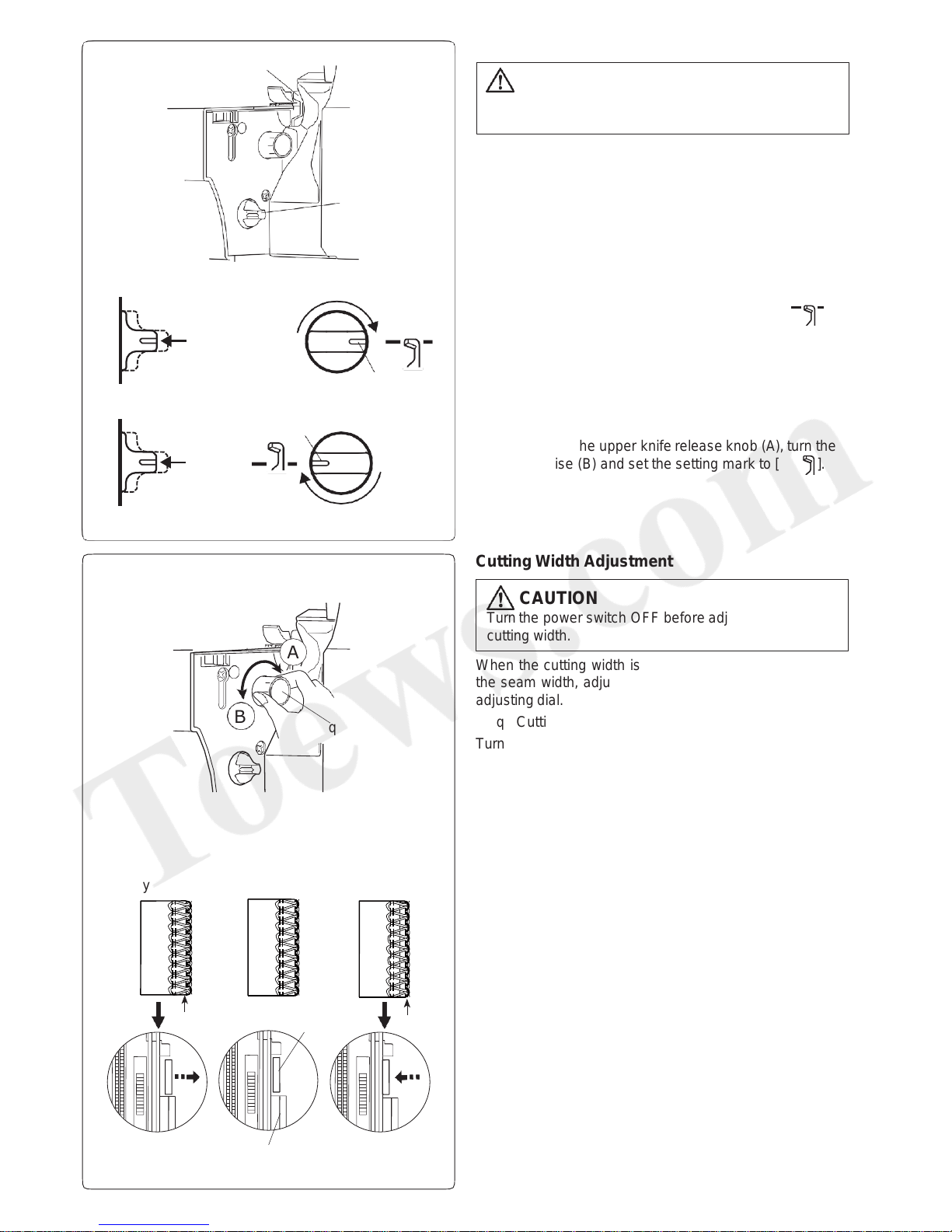
To Deactivate or Activate the Upper Knife
Cutting Width Adjustment
When the cutting width is too narrow or too wide for
the seam width, adjust it by turning the cutting width
adjusting dial.
q Cutting width adjusting dial
Turn the cutting width adjusting dial to get the desired
position of the lower knife.
When the lower knife is set to the standard position, the
right edge of the lower knife is aligned with the guide line
on the needle plate.
w Standard position
e Lower knife
r Guide on the needle plate
t Edge of fabric
If the cutting width is too narrow y, turn the cutting width
adjusting dial clockwise (to the direction of A).
The lower knife moves to right.
If the cutting width is too wide u , turn the cutting width
adjusting dial counterclockwise (to the direction of B).
The lower knife moves to left.
Sew and check the cutting width.
(A)
(B)
(A)
(B)
A
B
q
w
e
e
CAUTION
Turn the power switch OFF before deactivating or
activating the upper knife.
CAUTION
Turn the power switch OFF before adjusting the
cutting width.
q
w
e
r
t
t
y u
To deactivate:
While pressing the upper knife release knob (A), turn the
knob clockwise (B) and set the setting mark to [ ].
e Setting mark
12
To activate:
While pressing the upper knife release knob (A), turn the
knob clockwise (B) and set the setting mark to [ ].
Page 14
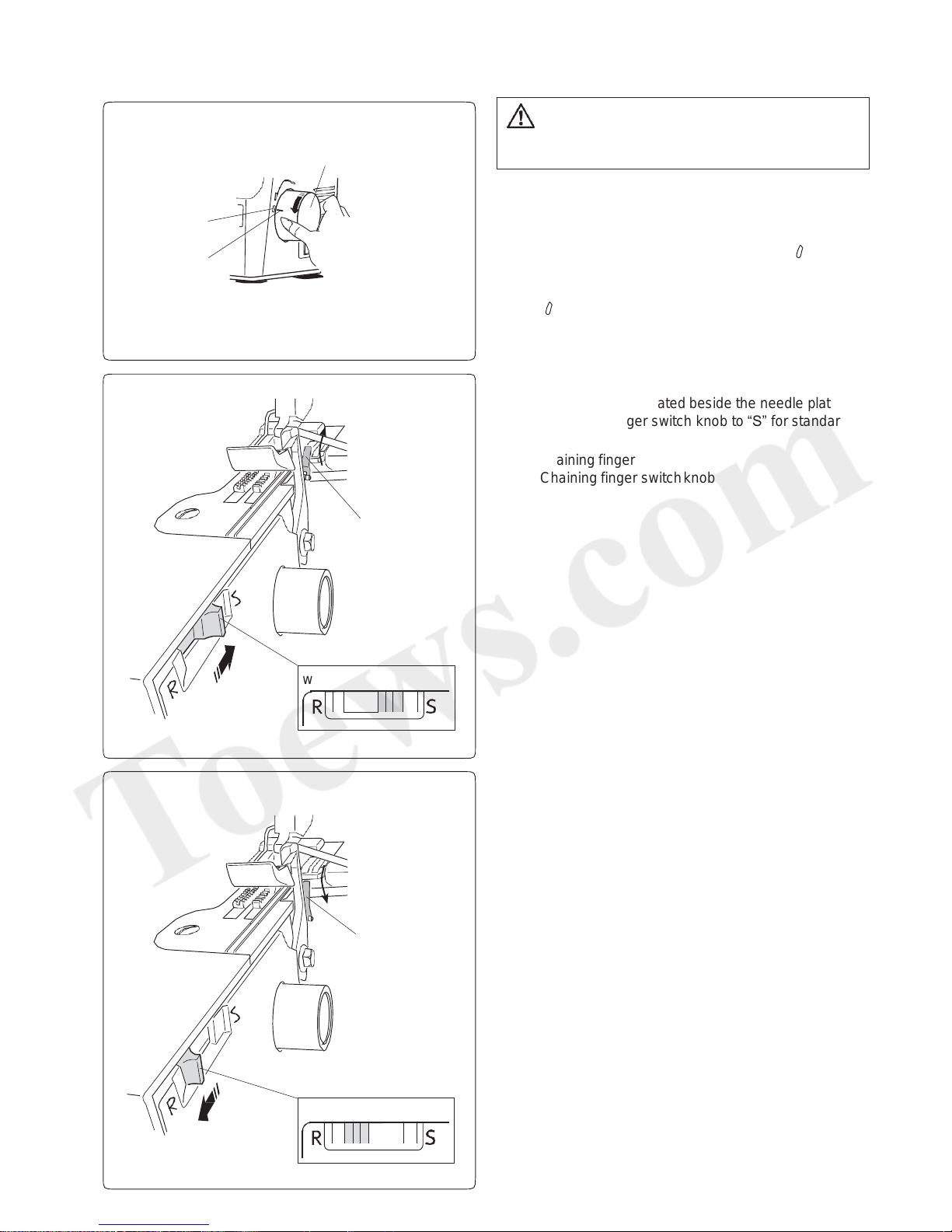
Chaining Finger Switch Knob Adjustment
(Changing to Standard Serging or Rolled
Hemming)
Standard serging
The chaining finger is located beside the needle plate.
Turn the chaining finger switch knob to “S” for standard
serging.
q Chaining finger
w Chaining finger switch knob
Rolled hemming
Turn the chaining finger switch knob to “R” for rolled for
hemming, picot edging or narrow hemming sewing.
q Chaining finger
w Chaining finger switch knob
CAUTION
Turn the power switch OFF before adjusting the
chaining finger switch knob.
q
q
w
w
q
w
e
The chaining finger switch knob is connected to the
chaining finger.
The chaining finger slides back and forth when you set
the chaining finger switch knob to “S” or “R”.
Turn the handwheel toward you to match the “ ” mark on
the belt cover with the “–” mark on the handwheel.
q Handwheel
w “ ” mark
e “–” mark
13
Page 15
Position of Thread Guide Bar
Pull the thread guide bar up as far as it will go.
q Thread guide bar
Turn the thread guide bar until it snaps into place.
Be sure to snap both stoppers into places.
The thread guide bar is placed right above the spool pins
as shown.
w Thread guide
e Stopper
r Spool pin
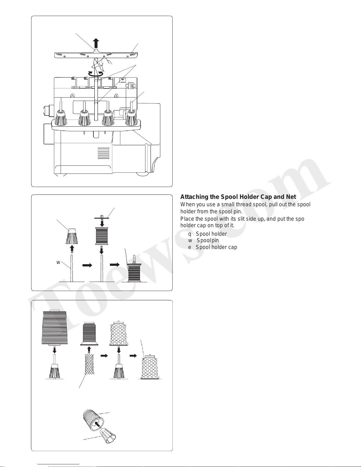
Attaching the Spool Holder Cap and Net
When you use a small thread spool, pull out the spool
holder from the spool pin.
Place the spool with its slit side up, and put the spool
holder cap on top of it.
q Spool holder
w Spool pin
e Spool holder cap
If the thread slips down from the spool during threading
and/or sewing, put a net on the spool as illustrated to
prevent jamming.
r Net
q
w
e
r
14
e
q
w
q
r
t
* Firmly insert the spool holder into the spool.
q Spool holder
t Spool
Page 16
MACHINE THREADING
Threading the Machine (4 threads)
q w e r
t
CAUTION
Turn the power switch OFF before threading the
machine.
15
NOTE:
• The looper threader can be used with standard
threads #60 - #100.
• The looper threader cannot be used with special
threads, such as wooly nylon, gold thread, etc.
For threading, refer to “Using the looper threading
wire”
(page 26) or “Using a standard thread” (page 27).
• For general sewing, standard threads #60 - #100
are used as needle thread.
• Do not use poor quality thread.
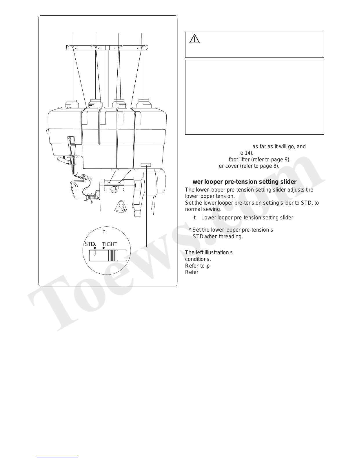
Preparation
Pull the thread guide bar up as far as it will go, and set
the spools (refer to page 14).
Raise the presser foot lifter (refer to page 9).
Open the looper cover (refer to page 8).
Lower looper pre-tension setting slider
The lower looper pre-tension setting slider adjusts the
lower looper tension.
Set the lower looper pre-tension setting slider to STD. to
normal sewing.
t Lower looper pre-tension setting slider
* Set the lower looper pre-tension setting slider to
STD.when threading.
The left illustration shows the completed threading
conditions.
Refer to pages 19-21 for threading the lower looper.
Refer to pages 22-24 for threading the upper looper.
Refer to pages 28-30 for threading the right needle.
Refer to pages 31-32 for threading the left needle.
q Left needle thread
w Right needle thread
e Upper looper thread
r Lower looper thread
Page 17
NOTE:
Partially tighten the needle clamp screw on the side
that is not being used to prevent losing the screw (refer
to page 10).
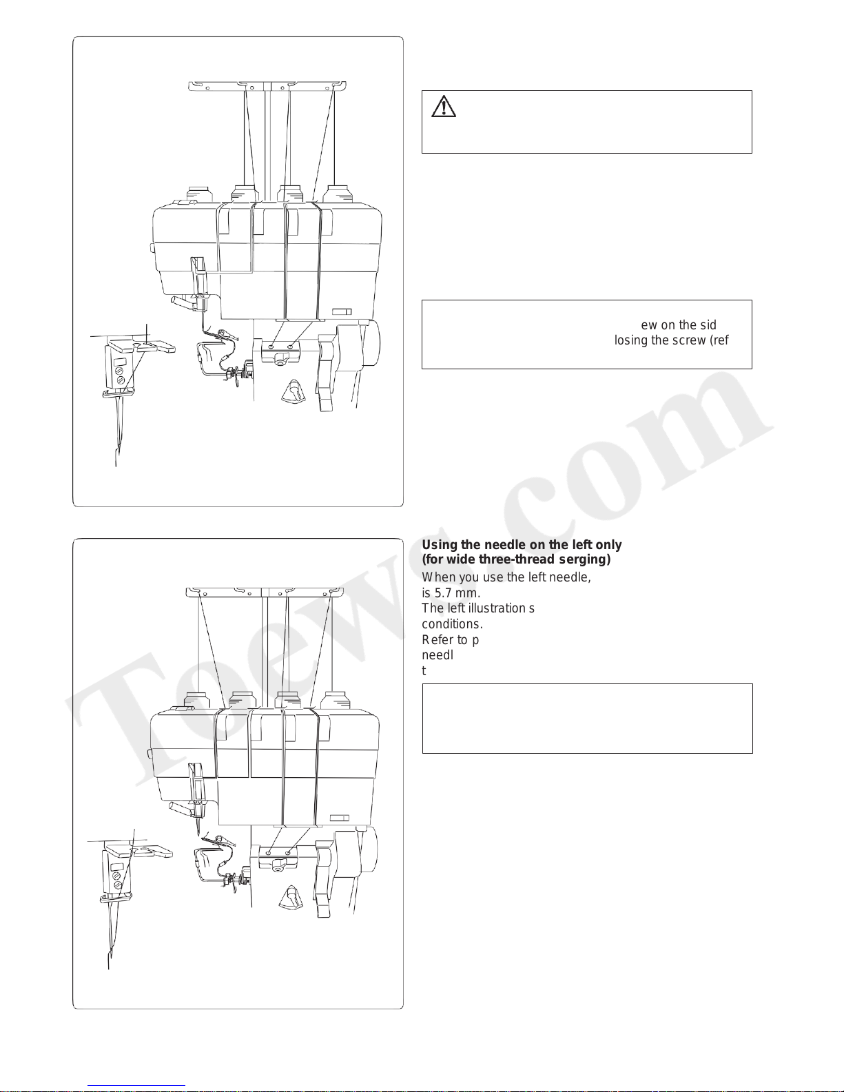
Threading the Machine (3 threads)
You can sew three-thread serging using the right needle
or the left needle.
Using the needle on the right only
(for regular three-thread serging)
When you use the right needle, the standard sewing
width is 3.5 mm.
The left illustration shows the completed threading
conditions.
Refer to pages 28-29 for details on how to thread the
right needle and page 30 for details on how to use the
needle threader.
CAUTION
Turn the power switch OFF before threading the
machine.
16
Using the needle on the left only
(for wide three-thread serging)
When you use the left needle, the standard sewing width
is 5.7 mm.
The left illustration shows the completed threading
conditions.
Refer to pages 31-32 for details on how to thread the left
needle and page 30 for details on how to use the needle
threader.
NOTE:
Partially tighten the needle clamp screw on the side
that is not being used to prevent losing the screw (refer
to page 10).
Page 18
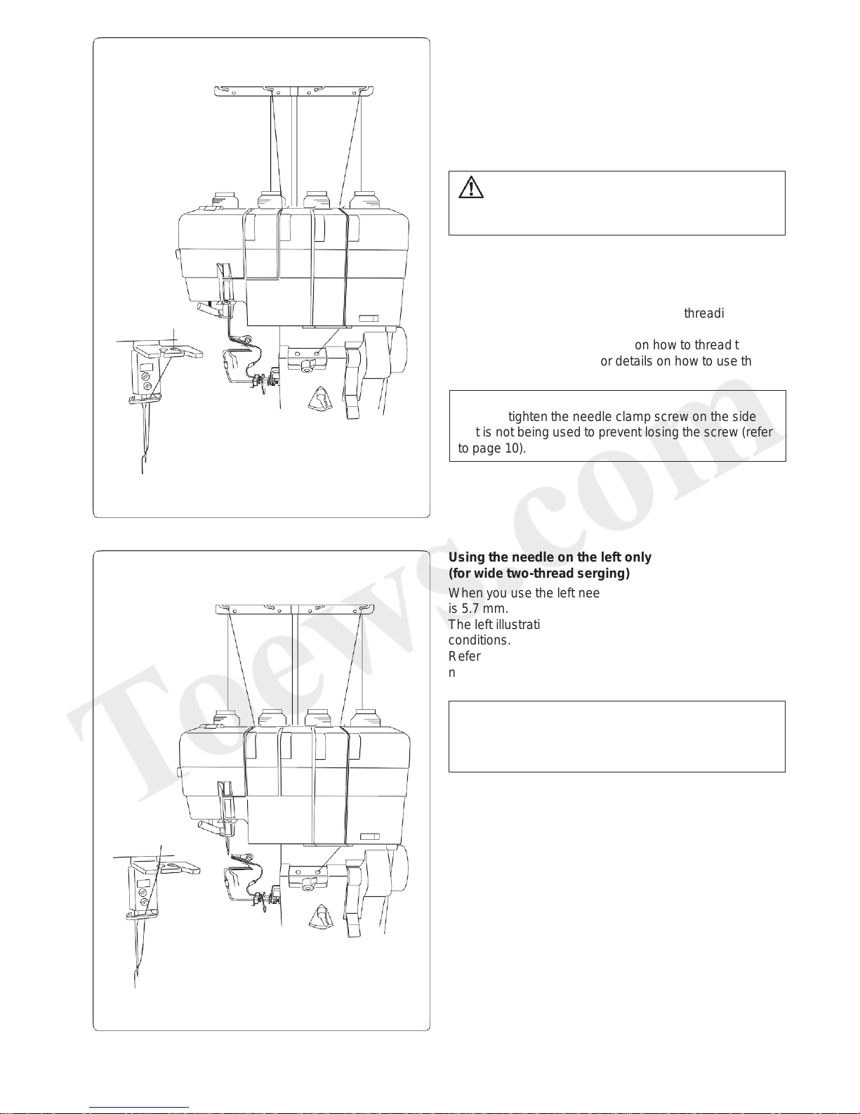
Threading the Machine (2 threads)
You can sew two-thread serging using the right needle or
the left needle.
Use the lower looper and the spreader.
Refer to page 18 for details on how to raise and lower the
spreader.
Using the needle on the right only
(for regular two-thread serging)
When you use the right needle, the standard sewing
width is 3.5 mm.
The left illustration shows the completed threading
conditions.
Refer to pages 28-29 for details on how to thread the
right needle and page 30 for details on how to use the
needle threader.
CAUTION
Turn the power switch OFF before threading the
machine.
17
Using the needle on the left only
(for wide two-thread serging)
When you use the left needle, the standard sewing width
is 5.7 mm.
The left illustration shows the completed threading
conditions.
Refer to pages 31-32 for details on how to thread the left
needle and page 30 for details on how to use the needle
threader.
NOTE:
Partially tighten the needle clamp screw on the side
that is not being used to prevent losing the screw (refer
to page 10).
NOTE:
Partially tighten the needle clamp screw on the side
that is not being used to prevent losing the screw (refer
to page 10).
Page 19

Using the Spreader for Two-thread Serging
Use the spreader pin (needle holder) to raise or lower the
spreader.
Raising the spreader
z Turn the handwheel toward you to match the “ ” mark
on the belt cover with the “–” mark on the handwheel.
Raise the needle.
q Handwheel
w “ ” mark
e “–” mark
x Insert the spreader pin into the small hole in the
spreader and turn the spreader pin counterclockwise
until the hook comes to the tip of the upper looper.
(Slightly turn the needle holder so that the needle
holder does not touch the upper knife.)
r Spreader pin
t Hook
y Small hole
u Spreader
i Upper looper
o Upper knife
c Slightly push the spreader pin so that the hook goes
behind the bulge of the upper looper and into the hole
in the upper looper.
!0 Bulge
v Remove the spreader pin from the spreader.
!1 Hole of upper looper
(Upper view of the upper looper)
q
w
e
r
r
t
t
(Rear view of the upper looper)
t
y
u i
i
i
o
!0
!0
!1
z
z
x
x c
c v
CAUTION
Turn the power switch OFF before raising or lowering
the spreader.
Lowering the spreader
z Insert the spreader pin into the small hole in the
spreader.
Slightly push the spreader and turn it clockwise so
that the hook comes over the bulge.
(Slightly turn the needle holder so that the needle
holder does not touch the upper knife.)
r Spreader pin
i Upper looper
!0 Bulge
x Turn the spreader clockwise to the original position
(until the spreader clicks).
c Remove the spreader pin from the spreader.
Correct Wrong
18
Page 20

NOTE:
Raise the presser foot lifter for easier threading.
z Draw the thread through the right side thread guide
from back to front: (A)
q Thread guide
Threading the Lower Looper
CAUTION
Turn the power switch OFF before threading the
machine.
z
x
c
b
v
(A)
(B)
q
e
r
r
t
z
19
x
w
c
v
y
b
u
x Slide the thread under the top cover thread guide as
illustrated.
w Top cover thread guide
c Pull the thread along the slit.
Using both hands, insert the thread between the
tension disks of the lower looper thread tension dial.
e Thread
r Tension disk
t Lower looper thread tension dial
v Set the lower looper pre-tension setting slider to STD.
y Lower looper pre-tension setting slider
b Draw the thread along the slit and pass it through the
right slit of the looper thread guide.
u Right slit of looper thread guide
NOTE:
If the thread tends to slip away from the guide while
sewing, pass the thread through both thread guide
holes as shown: (B)
Page 21

Looper selection lever
Turn the looper selection lever to the right to
thread the lower looper.
Turn the looper selection lever to the left to
thread the upper looper.
⁄ 0 Using the tweezers, insert the end of the thread 2 cm
or more into the threading hole on the right.
!2 Tweezers
!3 Threading hole on the right
!4 Thread (30 cm or longer)
!5 Thread end (2 cm or longer)
!2
!3
!4
!5
⁄0
n Pull out approximately 12˝ (30 cm) of thread. Make
sure that the thread does not get tangled around the
lever or the cover.
i Thread
m Set the looper threader switch lever to the
“THREADING” position.
o Looper threader switch lever
Adjusting the looper threader switch lever
Set the looper threader lever to the
“THREADING” position by turning it to the
right.
Set the looper threader lever to the “SEWING”
position by turning it to the left.
i
o
n m
,
!0
.
!1
,
20
⁄0
.
n m
, Turn the handwheel toward you slowly until it clicks.
This locks the handwheel in place.
!0 Handwheel
. Turn the looper selection lever to the “LOWER LOOPER”
position.
!1 Looper selection lever
NOTE:
• Trim the thread end so that it can be inserted into
the threading hole smoothly.
• If threading special threads, such as wooly nylon,
etc., refer to pages 26 and 27.
Page 22

⁄ 1 Raise the looper threader lever until it clicks into
place.
!6 Looper threader lever
!6
⁄1
!6
⁄2
!7
!8
!9
@0
@1
⁄3
⁄4
@2
⁄5
o
⁄ 2 Lower the looper threader lever until it knocks into
place.
21
⁄ 3 Make sure that the thread comes out from the hole of
the lower looper tip.
!7 Thread end
!8 Hole of lower looper tip
* If the thread does not come out from the hole,
follow the procedure from step ⁄1 again.
* If the thread comes out behind the pipe, use the
tweezers to draw the thread toward you between
the lower looper and the pipe.
!9 Thread (behind the pipe)
@0 Pipe
@1 Lower looper
⁄ 4 Draw 4˝ (10 cm) of the thread under the toe of the foot,
and pull it to the rear between the foot and the upper
knife.
@2 Upper knife
⁄ 5 Return the lower threader switch lever to the “SEWING”
position.
o Lower threader switch lever
Close the looper cover and lower the presser foot
lifter.
Page 23

z
c
z
x
c
v
(A) (B)
q
x
w
e
r
r
t
v
y
Threading the Upper Looper
z Draw the thread through the thread guide from back
to front: (A)
q Thread guide
x Slide the thread under the top cover thread guide as
illustrated.
w Top cover thread guide
c Pull the thread along the slit.
Using both hands, insert the thread between the
tension disks of the upper looper thread tension dial.
e Thread
r Tension disk
t Upper looper thread tension dial
v Draw the thread along the slit and pass it through the
left slit of the looper thread guide.
y Left slit of looper thread guide
NOTE:
Raise the presser foot lifter for easier threading.
CAUTION
Turn the power switch OFF before threading the
machine.
22
NOTE:
If the thread tends to slip away from the guide while
sewing, pass the thread through both thread guide
holes as shown: (B)
Page 24

Turn the looper selection lever to the left to
thread the upper looper.
. Using the tweezers, insert the end of the thread 1˝
(2 cm) or more into the threading hole on the right.
!1 Tweezers
!2 Threading hole on the right
!3 Thread (12˝ (30 cm) or longer)
!4 Thread end (1˝ (2 cm) or longer)
b Pull out approximately 12˝ (30 cm) of thread. Make
sure that the thread does not get tangled around the
lever or the cover.
u Thread
n Set the looper threader switch lever to the
“THREADING” position.
i Looper threader switch lever
Adjusting the looper threader switch lever
Set the looper threader lever to the
“THREADING” position by turning it to the right.
Set the looper threader lever to the “SEWING”
position by turning it to the left.
m Turn the handwheel toward you slowly until it clicks.
This locks the handwheel in place.
o Handwheel
, Turn the looper selection lever to the “UPPER LOOPER”
position.
!0 Looper selection lever
Looper selection lever
Turn the looper selection lever to the right to
thread the lower looper.
NOTE:
• Trim the thread end so that it can be inserted into
the threading hole smoothly.
• If threading special threads, such as wooly nylon,
etc., refer to pages 26 and 27.
u
i
b n
m
o
,
!0
.
!1
!2
!3
!4
m
23
.
,
b n
Page 25

⁄0
⁄4
⁄2
⁄3
!5
⁄1
!5
!8
!6
!7
i
⁄ 0 Raise the looper threader lever until it clicks into
place.
!5 Looper threader lever
24
⁄ 1 Lower the looper threader lever until it knocks into
place.
⁄ 2 Make sure that the thread comes out from the hole of
the upper looper tip.
!6 Thread end
!7 Hole of lower looper tip
⁄ 3 Draw 4˝ (10 cm) of the thread under the toe of the foot,
and pull it to the rear between the foot and the upper
knife.
!8 Upper knife
⁄ 4 Return the lower threader switch lever to the “SEWING”
position.
i Lower threader switch lever
Close the looper cover and lower the presser foot
lifter.
NOTE:
If the thread does not come out from the hole, follow
the procedure from step ⁄0 again.
Page 26

Instructions for using the looper threader
1. If either the upper or lower looper thread breaks while sewing, cut both of the upper and lower threads in front of
the threading holes, and remove the thread from the holes. Rethread both of the threads.
2. When the looper threader switch lever is in the “THREADING” position, the handwheel is locked. Even if the foot
control is depressed, the handwheel does not rotate.
Do not turn the handwheel. Doing so may cause malfunction.
3. After threading loopers, lower the looper threader lever and return the looper threader switch lever to “SEWING”
position.
25
Page 27

Threading Loopers with the Looper Threading
Wire or Standard Thread
If the looper threads are made from materials that are
difficult to thread, such as wooly nylon, there are 2
ways to thread the looper threads:
• Use the looper threading wire (looper threader)
• Tie the thread to standard thread, which you then
use to thread.
q
e
r
t
t
z x
c
q
w
v b
n m
,
CAUTION
Turn the power switch OFF before threading the
machine.
Using the looper threading wire
z Pass the thread up to the looper thread guide (before
the looper threader hole).
x Set the looper threader switch lever to the
“THREADING” position.
q Looper threader switch lever
c Turn the handwheel toward you slowly until it clicks.
This locks the handwheel in place.
w Handwheel
v Pass the straight end (not the loop end) through the
looper threader hole until it comes out from the the
hole of the looper tip.
e Loose end of looper threading wire
r Looper threader hole
b Pass approximately 2˝ (5 cm) thread through the loop
of the looper threading wire.
t Thread
n Pull the loose end of the looper threading wire until
the thread comes out from the hole of the looper tip.
m Remove the thread from the looper threading wire.
, Return the looper threader switch lever to the
“SEWING” position.
CAUTION
Do not raise or lower the looper thread lever while
threading.
26
Page 28

Using a standard thread
z Pass the thread up to the looper thread guide (in front
of the looper threader hole).
q Looper thread
x Prepare 12˝ (30 cm) of a standard thread and tie it 5
cm from the end of the looper thread as shown.
w Standard thread
e Knot
r 5 cm
t
c
y
v
u
i
b
Figure A
,
t
q
m
q
e
z x
q
w
e
r
x
o
n
z
q
q
27
NOTE:
when tying the standard thread to the looper thread,
tie a knot as small as possible and cut any excess
standar thread.
c Set the looper threader switch lever to “THREADING”
position.
t Looper threader switch lever
v Turn the handwheel toward you slowly until it clicks.
This locks handwheel in place.
y Handwheel
b Using the tweezers, insert approximately 1˝ (2 cm) of
the standard thread into the threading hole.
u Tweezers
i Looper threader hole
n Raise the looper threader lever until it clicks into
place.
Lower the looper threader lever until it knocks into
place.
o Looper threader lever
m Pull out approximately 4˝ (10 cm) of the standard
thread from the hole in the looper tip and trim it at the
knot.
* When the knot reaches the looper threader hole,
fold the loose end of the looper thread as illustrated
by figure A in procedure b.
, Return the looper threader switch lever to the
“SEWING” position.
Replacing threaded looper thread
z Cut the threaded looper thread between the thread
guide and the top cover thread guide.
q Thread guide
w Top cover thread guide
w
x Set a new spool of looper thread.
Pass the new looper thread through the thread guide,
and tie it to the end of the threaded looper thread.
Tie a knot as small as possible.
e Knot
c
e
c Slowly pull the threaded looper thread out from the
hole of the looper tip until the knot comes out.
Page 29

(A) (B)
q
e
r
r
t
z
x
c
z
x
w
c
Threading the Right Needle
z Draw the thread through the thread guide from back
to front: (A)
q Thread guide
x Slide the thread under the top cover thread guide as
illustrated.
w Top cover thread guide
c Pull the thread along the slit.
Using both hands, insert the thread between the
tension disks of the right needle thread tension dial.
e Thread
r Tension disk
t Right needle thread tension dial
NOTE:
Raise the presser foot lifter for easier threading.
CAUTION
Turn the power switch OFF before threading the
machine.
28
NOTE:
If the thread tends to slip away from the guide while
sewing, pass the thread through both thread guide
holes as shown: (B)
Page 30

v Pull the thread down along the slit and draw it to the
left through the thread path.
y Slit
u Thread path
b Pull the thread up and along the left side of the thread
take-up lever cover and pass it over the take-up lever
thread guide.
i Thread take-up lever cover
o Thread take-up lever thread guide
v b
v
b
n
m
n m ,
. ⁄0
y
u
u
i
o
o
i
!0
!1
!2
!3
29
n Pass the thread through the right slit of the needle
thread guide.
!0 Needle thread guide
m Pass the thread through the needle bar thread guide
from left to right.
!1 Needle bar thread guide
, Thread the right needle from front to back.
!2 Right needle
* Use the needle threader (refer to page 30).
. Pull out approximately 4˝ (10 cm) of thread from the
needle and slide it under the foot so that it runs in
between the foot and the upper knife.
!3 Upper knife
⁄ 0 Close the looper cover and lower the presser foot
lifter.
* Refer to pages 31 and 32 for details on how to
thread the left needle.
Page 31

Using the needle threader
Following the procedure m on page 29 or page 32,
thread the needles with the needle threader shown
below.
z Turn the handwheel toward you to match the “o” mark
on the belt cover with the “-” mark on the handwheel.
q Handwheel
x Lower the presser foot lifter.
w Presser foot lifter
CAUTION
Turn the power switch OFF before threading the
machine.
q
R
L
e
r
u
z
30
x
w
c
v
r
b
t
y
n
m
c Set the needle threader switch lever to R when
threading the right needle.
Set the needle threader switch lever to L when
threading the left needle.
e Needle threader switch lever
v Pull down the needle threader lever as far as it will go.
r Needle threader lever
b Draw the thread along the guide on the needle
threader switch lever from the left and under the hook.
t Guide
y Hook
* Make sure that the thread or your finger does not
touch the upper looper or the upper knife.
n Slowly raise the threader lever so that a loop of the
thread is pulled up through the needle.
r Needle threader lever
u Loop
m Pull the thread loop and draw out the thread end to
the rear through the needle eye.
Page 32

z
c
(A)
(B)
q
x
w
e
r
r
t
z
x
c
Threading the Left Needle
z Draw the thread through the thread guide from back
to front: (A)
q Thread guide
x Slide the thread under the top cover thread guide as
illustrated.
w Top cover thread guide
c Pull the thread along the slit.
Using both hands, insert the thread between the
tension disks of the left needle thread tension dial.
e Thread
r Tension disk
t Left needle thread tension dial
NOTE:
Raise the presser foot lifter for easier threading.
CAUTION
Turn the power switch OFF before threading the
machine.
31
NOTE:
If the thread tends to slip away from the guide while
sewing, pass the thread through both thread guide
holes as shown: (B)
Page 33

v Pull the thread down and along the slit and draw it to
the left through the thread path.
y Slit
u Thread path
b Pull the thread up and along the left side of the thread
take-up lever cover and pass it over the take-up lever
thread guide.
i Thread take-up lever cover
o Thread take-up lever thread guide
v b
n m ,
. ⁄0
b
v
n
m
i
o
u
u
y
i
!0
!1
!2
!3
32
o
n Pass the thread through the left slit of the needle
thread guide.
!0 Needle thread guide
m Pass the thread through the needle bar thread guide
from left to right.
!1 Needle bar thread guide
, Thread the left needle from front to back.
!2 Left needle
* Use the needle threader (refer to page 30).
. Pull out approximately 4˝ (10 cm) of thread from the
needle and slide it under the foot so that it runs in
between the foot and the upper knife.
Refer to pages 28 and 29 for details on how to thread
the right needle.
⁄ 0 Close the looper cover and lower the presser foot
lifter.
Page 34

Thread and Needle Chart
Type of fabric
Thread
Needle
Stitch
length dial
Differential
feed dial
Chaining
finger switch
knob
Lower looper
pre-tension
setting slider
Upper knife
Light weight
Organdy,
Georgette,
Lawn,
Crepe de chine,
Lining
Synthetic
#80-100
HAx1SP
#11-14
2.0-3.0
0.5-1.0
S
STD.
Activated
Medium weight
Cotton, Linen,
Satin,
Ordinary fabric
Synthetic
#60-100
HAx1SP
#14
2.5-3.5
1.0
Heavy weight
Tweed,
Coating, Denim,
Doeskin,
Thick fabric
Synthetic
#50-100
HAx1SP
#14
3.0-5.0
1.0
Knits
Knitted fabric
Synthetic
#60-90
Woolly nylon
(for upper
looper)
HAx1SP
#11-14
2.5-3.5
1.0-2.0
* For details on how to adjust the stitch length and the differential feed ratio, refer to pages 37-38 (4 threads), page 39 (3
threads) or page 40 (2 threads).
* Use wooly nylon thread as upper looper thread for rolled hemming, picot edging and narrow hemming.
33
Page 35

TEST STITCHING
Starting Sewing
z Close the side cover and the looper cover.
Turn the power switch ON.
x Make sure that the upper knife is activated (in the
raised position).
c Lower the presser foot lifter.
v Draw all of the threads back under the foot. Slowly
run the machine and produce a 2˝ (5 cm) thread chain
while gently pulling the thread chain to the back.
Check the chain.
b Insert the fabric under the toe of the foot. (You do
not need to raise the foot.) Start sewing slowly. The
fabric will automatically be fed. Guide the fabric in the
desired direction.
* For heavyweight fabric, raise the presser foot and
insert the fabric in front of the knife. Lower the foot
and start to sew while guiding the fabric.
Finishing Sewing
z After stitching is complete, continue to slowly produce
approximately 5˝ (12 cm) of thread chain while gently
pulling the thread chain to the back.
q
34
z
x
x Cut the threads with the thread cutter as illustrated,
leaving a thread chain approximately 2˝ (5 cm) long
on the end of the fabric.
q Thread cutter
Page 36

Sewing Continuously
Insert the next piece of the fabric under the toe of the
foot, and start sewing. You do not need to raise the
presser foot for ordinary fabric.
* For heavyweight fabric, raise the presser foot and insert
the fabric in front of the knife. Lower the foot and start
sewing while guiding the fabric.
35
q
Using Guide Lines
The guide lines on the top of the looper cover help you to
measure the distance from the right needle drop position.
The numbers on the top of the looper cover indicate the
distance from the right needle position in inches.
q 5/8˝ to the right of the right needle position
* The cutting width between the right needle position and
the upper knife when in the standard position (refer to
page 12) is 3.5 mm.
Page 37

Securing Ends
To avoid raveling, you need to leave a thread chain
approximately 2˝ (5 cm) long at the beginning and at the
end of a seam. To secure the beginning and end of a
seam, choose one of the following methods.
At the beginning of the seam
A. Separate and tie the thread ends together.
B. Thread the chain through a large eyed needle, and
weave that chain through the overlock stitches on the
fabric.
C. Cut the chain at the edge of the fabric, and apply a
small amount of seam sealant (Fray Check™ or Fray-
No-More™) to the thread ends.
D. Securing the beginning w ith the machine
z Before putting your fabric in the machine, sew a
thread chain approximately 2˝ (5 cm) long behind
the needle.
x Put your fabric on the machine. Serge a few
stitches and stop.
c Raise the presser foot and bring the thread chain
to the left around and under the presser foot.
v Place the thread chain between the presser foot
and upper knife, holding it in position as you lower
the presser foot to sew.
b After sewing approximately 1˝ (2.5 cm), move the
chain to the right and under the upper knife, cutting
the chain as you sew.
D
A
B
C
At the end of the seam
Securing the seam end with the machine
z Serge one stitch off the end of the seam.
x Raise the needle and presser foot, and gently pull the
threads off the chaining finger.
c Turn the fabric over so that the under side is up.
v Serge approximately 1˝ (2.5 cm) over the stitching and
angle off the fabric.
E
Cutting the Seams
Cut the upper looper thread with a seam ripper (not
included with the machine) to cut the seams.
q Upper looper thread
w Seam ripper
q
36
w
z
z
x c v b
x
c
v
Page 38

Thread Tension (4 threads)
Correct tension
The illustration to the left shows a seam sewn at the
correct tension. Note that you may need to adjust the
thread tension depending on the fabric and thread being
used.
q Wrong side of fabric
w Right side of fabric
e Right needle thread
r Left needle thread
t Upper looper thread
y Lower looper thread
Left needle thread tension is too loose
The illustration to the left shows a seam sewn when the
left needle thread tension is too loose.
Remedy:
Tighten the left needle thread tension.
!1 Left needle tension dial
Right needle thread tension is too loose
The illustration to the left shows a seam sewn when the
right needle thread tension is too loose.
Remedy:
Tighten the right needle thread tension.
!2 Right needle tension dial
Thread tension adjustment
Set all four thread tension dials to “3”.
Sew and check the thread tension.
If the tension on the test piece is not satisfactory, you can
adjust the thread tension with the thread tension dial.
u Thread tension dial
i Setting mark
o Loosen
!0 Tighten
u
i
o
!0
q
w
e
r
t
y
q
e
r
w
t
y
!1
!2
37
q
e
r
w
t
y
Page 39

Looper thread tension is out of balance (1)
The illustration shows sewing results when the lower
looper thread tension is too tight and/or upper looper
thread tension is too loose.
38
Remedy:
Loosen lower looper thread tension and/or tighten upper
looper thread tension.
q Wrong side of fabric
w Right side of fabric
e Right needle thread
r Left needle thread
t Upper looper thread
y Lower looper thread
!3 Upper looper thread tension dial
!4 Lower looper thread tension dial
Looper thread tension is out of balance (2)
The illustration to the left shows a seam sewn when the
upper looper thread tension is too tight and/or the lower
looper thread tension is too loose.
Remedy:
Loosen the upper looper thread tension and/or tighten
the lower looper thread tension.
!3 Upper looper thread tension dial
!4 Lower looper thread tension dial
q
w
e
r
t
y
!3
!3
!4
!4
q
w
e
r
t
y
Page 40

Thread Tension (3 threads)
Correct tension
The illustration to the left shows a seam sewn at the
correct tension. Note that you may need to adjust the
thread tension depending on the fabric and thread being
used.
q Wrong side of fabric
w Right side of fabric
e Right or left needle thread
r Upper looper thread
t Lower looper thread
q
w
e
r
t
y
39
u
i
o
q
w
e
r
t
!0 !1
q
w
e
r
t
!2 !3
q
w
e
r
t
!2 !3
Thread tension adjustment
Set the three thread tension dials to “3”.
Sew and check the thread tension.
If the tension on the test piece is not satisfactory, you can
adjust the thread tension with the thread tension dial.
y Thread tension dial
u Setting mark
i Loosen
o Tighten
Needle thread tension is too loose
The illustration to the left shows a seam sewn when the
left needle thread tension is too loose.
Remedy:
Tighten the needle thread tension.
!0 Left needle tension dial
!1 Right needle tension dial
Looper thread tension is out of balance (1)
The illustration to the left shows a seam sewn when the
lower looper thread tension is too tight and/or the upper
looper thread tension is too loose.
Remedy:
Loosen the lower looper thread tension and/or tighten the
upper looper thread tension.
!2 Upper looper thread tension dial
!3 Lower looper thread tension dial
Looper thread tension is out of balance (2)
The illustration to the left shows a seam sewn when the
upper looper thread tension is too tight and/or the lower
looper thread tension is too loose.
Remedy:
Loosen the upper looper thread tension and/or the tighten
lower looper thread tension.
!2 Upper looper thread tension dial
!3 Lower looper thread tension dial
Page 41

Thread Tension (2 threads)
Correct tension
The illustration to the left shows a seam sewn at the
correct tension. Note that you may need to adjust the
thread tension depending on the fabric and thread being
used.
q Wrong side of fabric
w Right side of fabric
e Right or left needle thread
r Lower looper thread
Thread tension adjustment
Set the lower looper pre-tension setting slider to TIGHT.
Set the two thread tension dials to “3”.
Sew and check the thread tensions.
If the tension on the test piece is not satisfactory, you can
adjust the thread tension with the thread tension dial.
t Thread tension dial
y Setting mark
u Loosen
i Tighten
Needle/Lower looper thread tension is out of
balance (1)
The illustration to the left shows a seam sewn when the
lower looper thread tension is too tight and/or the needle
thread tension is too loose.
Remedy:
Loosen the lower looper thread tension and/or the tighten
upper looper thread tension.
o Left needle thread tension dial
!0 Right needle thread tension dial
!1 Lower looper thread tension dial
q
w
e
r
t
y
u
i
q
w
e
r
o !0 !1
Needle/Lower looper thread tension is out of
balance (2)
40
The illustration to the left shows a seam sewn when the
needle thread tension is too tight and/or the lower looper
thread tension is too loose.
Remedy:
Loosen the needle thread tension and/or tighten the
lower looper thread tension.
o Left needle thread tension dial
!0 Right needle thread tension dial
!1 Lower looper thread tension dial
q
w
e
r
o !0 !1
Page 42

Correct tension for rolled hem
The illustration to the left shows a seam sewn at the
correct tension. Note that you may need to adjust the
thread tension depending on the fabric and thread being
used.
41
Use synthetic thread for the needle thread and woolly
nylon thread for the lower looper thread.
Set the lower looper pre-tension setting slider to STD.
Other settings are same as the 3-threads rolled hem (refer
to page 42).
For best results, make a test run using the fabric
and threads you want to use and adjust the tension
accordingly.
q Wrong side of fabric
w Right side of fabric
e Needle thread
r Lower looper thread
q
w
e
r
Page 43

Rolled Hemming
Picot Edging
Narrow Hemming
Lower looper
pre-tension setting
slider
TIGHT
* Set the lower looper
pre-tension setting slider to
TIGHT after threading.
TIGHT
* Set the lower looper
pre-tension setting slider to
TIGHT after threading.
STD.
Standard setting of
tension dials
Right
needle
Upper
looper
Lower
looper
Right
needle
Upper
looper
Lower
looper
Right
needle
Upper
looper
Lower
looper
(Syntheti
c) 3-4
(Syntheti
c) 3
(Syntheti
c) 3
(Syntheti
c) 2-4
(Syntheti
c) 3
(Syntheti
c) 3
(Syntheti
c) 4
(Syntheti
c) 3
(Syntheti
c) 3
(Syntheti
c) 4
(Wooly
nylon
) 1
(Syntheti
c) 3
-
-
-
(Syntheti
c) 4
(Wooly
nylon
) 1
(Syntheti
c) 3
(Syntheti
c) 4
(Wooly
nylon
) 1
(Wooly
nylon
) 3
(Syntheti
c) 4
(Wooly
nylon
) 1
(Wooly
nylon
) 3
Stitch length dial
R
3-4
R
Differential feed
dial
1.0
1.0
1.0
Chaining finger
switch knob
R R R
Upper knife
Activated
Needle
Using the right needle: HA -1 SP No. 11
(Remove the left needle.)
Needle thread
Synthetic: No. 80 - 100
Fabric
Lightweight fabric such as organdy, crepe de chine, lawn and georgette
ROLLED HEMMING, PICOT EDGING AND NARROW HEMMING
Tension Dial and Machine Settings According to the Thread and Fabric
The setting of tension dials may vary depending on the
type and thickness of fabric and thread being sewn.
* Refer to page 10 for details on how to remove the needle.
* Refer to page 11 for details on how to adjust the stitch length.
* Refer to page 11 for details on how to adjust the difference ratio.
* Refer to page 13 for details on how to adjust the chaining finger switch knob.
* Refer to page 12 for details on how to deactivate and activate the upper knife.
CAUTION
Make sure to turn the power switch off before
changing the needle or setting the chaining finger
switch knob.
42
Page 44

For Better Results
Rolled hemming
Gently pull the end of thread chain to the back at the
beginning and end of sewing.
43
Picot edging
Gently pull the fabric to the back while sewing.
NOTE:
The sewing procedure of narrow hemming is the same
as that for standard overedging.
Page 45

Thread Tension
Correct tension
The illustration to the left shows a seam sewn at the
correct tension. Note that you may need to adjust the
thread tension depending on the fabric and thread being
used.
q Wrong side of fabric
w Right side of fabric
e Right needle thread
r Upper looper thread
t Lower looper thread
Thread tension adjustment
1. Set the tension dials as shown on page 42.
2. Sew and check the tension.
3. If the tension on the test piece is not satisfactory, you
can adjust the thread tension with thread tension dial.
Rolled hemming
Picot edging
q
w
e
r
t
q
t
w
e
r
Narrow hemming
q
w
e
r
t
44
Page 46

For rolled hemming and picot edging
* Thread tension adjustment for narrow hemming is the
same as that for 3-thread overedging (refer to page 39).
q Wrong side of fabric
w Right side of fabric
e Right needle thread
r Upper looper thread
t Lower looper thread
The lower looper thread tension is too tight and/or
the right thread tension is too loose
Remedy:
Tighten the right needle thread tension and/or loosen the
lower looper thread tension.
y Right needle thread tension dial
i Lower looper thread tension dial
q
w
e
r
t
y i
q
w
e
r
t
u
q
45
w
e
r
t
u i
The upper looper thread tension is too loose
Remedy:
Tighten the right needle thread tension.
u Upper looper thread tension dial
The lower looper thread tension is too loose and/or
the upper looper thread tension is too tight
Remedy:
Loosen upper looper thread tension and/or tighten lower
looper thread tension.
u Upper looper thread tension dial
i Lower looper thread tension dial
Page 47

Machine Setting
Lower looper
pre-tension
setting slider
STD.
Standard setting
of tension dials
Left
needle
Right
needle
Upper
looper
Lower
looper
5
5
1-2
6
Stitch length dial
3-4
Differential feed
dial
1.0
Chaining finger
switch knob
S
Upper knife
Activated
Needle
Use both the right and left needles:
HA-1 SP No. 14
Needle thread
Synthetic: No. 60 - 80
Upper looper
thread
Decorative thread
* Use the looper threading wire or a
standard thread for threading.
Lower looper
thread
Synthetic: No. 60 - 100
Fabric
Medium weight or heavy weight
ADVANCED TECHNIQUES
Decorative Overedging
q Left needle thread tension dial
w Right needle thread tension dial
e Upper looper thread tension dial
r Lower looper thread tension dial
t Chaining finger switch knob
y Upper knife release knob
u Stitch length dial
i Differential feed dial
o Lower looper pre-tension setting slider
* Refer to page 10 for details on how to remove the
needle.
* Refer to page 11 for details on how to adjust the
stitch length.
* Refer to page 11 for details on how to adjust the
difference ratio.
* Refer to page 12 for details on how to deactivate/
activate the upper knife.
* Refer to page 13 for details on how to adjust the
chaining finger switch knob.
CAUTION
Make sure to turn the power switch off before
changing the needle, deactivating/activating the upper
knife or setting the chaining finger switch knob.
w
q
46
e
r
t
y
u
i
o
NOTE:
• You may need to adjust the thread tension.
• For best results, gently pull the thread chain to the
back at the beginning and end of sewing.
Page 48

Gathering
Sew and check the thread tensions.
If the tension balance on the test piece is not satisfactory,
you can adjust the thread tension with the thread tension
dial.
* Adjust the differential feed dial between 1.0 and 2.0 for
gathering.
CAUTION
Make sure to turn the power switch off before
changing the needle, deactivating/activating the upper
knife or setting the chaining finger switch knob.
q
q Left needle thread tension dial
w Right needle thread tension dial
e Upper looper thread tension dial
r Lower looper thread tension dial
t Chaining finger switch knob
y Upper knife release knob
u Stitch length dial
i Differential feed dial
o Lower looper pre-tension setting slider
* Refer to page 10 for details on how to remove the
needle.
* Refer to page 11 for details on how to adjust the
stitch length.
* Refer to page 11 for details on how to adjust the
difference ratio.
* Refer to page 12 for details on how to deactivate/
activate the upper knife.
* Refer to page 13 for details on how to adjust the
chaining finger switch knob.
w e
r
t
y
u
i
o
Machine Setting
Lower looper
pre-tension
setting slider
STD.
Standard setting
of tension dials
Left
needle
Right
needle
Upper
looper
Lower
looper
3
3
3
3
Stitch length dial
3-4
Differential feed
dial
2.0
Chaining finger
switch knob
S
Upper knife
Activated
Needle
Use both the right and left needles:
HA-1 SP No. 14 or No. 11
Needle thread
Synthetic: No. 60 - 80
Upper looper
thread
Synthetic: No. 60 - 100
Lower looper
thread
Synthetic: No. 60 - 100
Fabric
Medium weight, light weight
47
Page 49

Sewing
z Sew the folded edge while guiding it along the guide
line.
q Right side of fabric
w Folded edge
e Guide line on the needle plate
x Open the fold flat and press the pintucks to one side.
* After you finish sewing, return the upper knife to the
original position (activated).
w
q
e
r
t
y
u
i
o
q
w
e
z
x
Machine Setting
Lower looper
pre-tension
setting slider
STD.
Standard setting
of tension dials
Left
needle
Right
needle
Upper
looper
Lower
looper
-
4
5-7
2-4
Stitch length dial
R
Differential feed
dial
1.0
Chaining finger
switch knob
R
Upper knife
Deactivated
Needle
Use the right needle:
HA-1 SP No. 14 or No. 11
Needle thread
Synthetic: No. 80 - 100
Upper looper
thread
Synthetic: No. 80 - 100
Lower looper
thread
Synthetic: No. 80 - 100
Fabric
Light weight, knit fabric
Pintucking
NOTE:
• You may need to adjust the thread tension
depending on the type of fabric and thread being
used.
• If the tension balance on the test piece is not
satisfactory, you can adjust the thread tension with
the thread tension dial.
CAUTION
Make sure to turn the power switch off before
changing the needle, deactivating/activating the upper
knife or setting the chaining finger switch knob.
q Left needle thread tension dial
w Right needle thread tension dial
e Upper looper thread tension dial
r Lower looper thread tension dial
t Chaining finger switch knob
y Upper knife release knob
u Stitch length dial
i Differential feed dial
o Lower looper pre-tension setting slider
* Refer to page 10 for details on how to remove the
needle.
* Refer to page 11 for details on how to adjust the
stitch length.
* Refer to page 11 for details on how to adjust the
difference ratio.
* Refer to page 12 for details on how to deactivate/
activate the upper knife.
* Refer to page 13 for details on how to adjust the
chaining finger switch knob.
48
Page 50

Flatlock
CAUTION
Make sure to turn the power switch off before
changing the needle, deactivating/activating the upper
knife or setting the chaining finger switch knob.
q
q Left needle thread tension dial
w Right needle thread tension dial
e Upper looper thread tension dial
r Lower looper thread tension dial
t Chaining finger switch knob
y Upper knife release knob
u Stitch length dial
i Differential feed dial
o Lower looper pre-tension setting slider
* Refer to page 10 for details on how to remove the
needle.
* Refer to page 11 for details on how to adjust the
stitch length.
* Refer to page 11 for details on how to adjust the
difference ratio.
* Refer to page 12 for details on how to deactivate/
activate the upper knife.
* Refer to page 13 for details on how to adjust the
chaining finger switch knob.
* Refer to page 18 for details on how to raise and
lower the spreader.
w e
r
t
y
u
i
o
Machine Setting
Lower looper
pre-tension
setting slider
STD.
Standard setting
of tension dials
(1 needle 3
threads)
Left
needle
Right
needle
Upper
looper
Lower
looper
0-2
-
0
6-7
Standard setting
of tension dials
(1 needle 2
threads)
Left
needle
Right
needle
Upper
looper
Lower
looper
0-2
-
-
7
Spreader
(1 needle 2
threads)
Stitch length dial
3-4
Differential feed
dial
1.0
Chaining finger
switch knob
S
Upper knife
Deactivated
Needle
Use the left needle:
HA-1 SP No. 14 or No. 11
Needle thread
Synthetic: No. 60 - 100
Upper looper
thread
Left
needle
Right
needle
Upper
looper
Lower
looper
Synthetic:
No.60-
100
Decorati
ve
thread
Synthetic:
No.60100
Lower looper
thread
Left
needle
Right
needle
Upper
looper
Lower
looper
Synthetic:
No.60100
Decorati
ve
thread
* Use the looper threading wire or a standard thread for
threading.
Fabric
Medium weight
49
NOTE:
• You may need to adjust the thread tension
depending on the type of fabric and thread being
used.
• If the tension balance on the test piece is not
satisfactory, you can adjust the thread tension with
the thread tension dial.
Page 51

r
Sewing
z Fold the fabric wrong sides together.
q Wrong side of fabric
50
x Adjust the seam width as twice as the cutting width.
c Sew a test piece and check the tensions.
w Needle thread
e Upper looper thread
r Lower looper thread
q
q
w
e
y
u
i
o
z x c
v b
v Deactivate the upper knife and sew.
b Open the fabric and iron the wrong side.
q Right side of fabric
y Seam width
u Cutting width
i Folded edge
o Wrong side of fabric
* Adjust the seam width according to the results.
Page 52

Sewing Corners
Outer corners
z Trim three corners (other than the starting point) 3 cm
as illustrated.
q Starting point
w Cutting line
e Trimmed corner
r 3 cm
Inner corners
z Cut the inner corner as illustrated.
q Inner corner
x Sew and stop 3 cm before the inner corner.
w Cutting line
e 3 cm
r Cutting allowance
z
q
w
e
r
w
t
x c v
q
w
e
r
z x
w
51
c v
x When you reach the next corner, stop the machine.
Raise the needle and the presser foot.
Remove the threads from the chaining finger and turn
the fabric.
Align the cutting line with the upper knife.
t Upper knife
c Lower the presser foot lifter.
v Continue to sew from where the previous stitches on
the corner ended.
c Turn the fabric so that the cutting lines are straight
and insert the fabric under the foot.
v Continue to sew.
Page 53

q
w
z
x c v
b
n m ,
q
e
r
t
y
u
i
o
!0
t
!1
r
e
Open the looper cover.
With a forward brushing movement, use the lint brush to
remove any lint.
q Lint brush
* You may use a vacuum cleaner to clean the upper
knife area or feed dog.
CARE OF YOUR MACHINE
Cleaning the Upper Knife Area
CAUTION
Make sure to turn the power switch off before cleaning
the machine.
CAUTION
Make sure to turn the power switch off before cleaning
the machine.
52
Cleaning the Feed Dog
z Position the chaining finger lower than the surface of
the needle plate by pulling the chaning finger switch
knob toward you to “R” (refer to page 13).
q Chaining finger
w Chaining finger switch knob
x Open the looper cover and the side cover.
c Remove the needle and the presser foot (refer to
pages 9 and 10).
v Remove the setscrew with the large screw driver and
remove the needle plate.
e Setscrew
r Needle plate
t Large screwdriver
b Use the lint brush to remove any lint from around the
feed dog.
y Feed dog
u Lint brush
n Attach the needle plate by inserting the rib under the
edge of the rear cover and aligning the hole in the
needle plate with the pin.
Tighten the setscrew with the screwdriver.
e Setscrew
r Needle plate
t Large screwdriver
i Needle plate hole
o Rib
!0 Pin
!1 Edge of rear cover
m Attach the needle and the presser foot.
, Close the side cover and the looper cover.
Page 54

Cleaning the Looper Threader Pipe
CAUTION
Make sure to turn the power switch off before cleaning
the machine.
z
q
w
x
53
c v b n
t
r
e
q
m
y
,
q
NOTE:
• Clean the looper threader pipe once every 10
hours of use or when the looper threader does not
work well.
• You can also use an compressed air duster or
camera dust blower to clean the looper threader
pipe.
Use the looper threading wire to clean the pipe of the
looper threader device.
z Open the looper cover and set the looper threader
switch lever to the “THREADING” position.
q Looper threader switch lever
x Turn the handwheel toward you slowly until it clicks.
w Handwheel
c Insert the straight end (not the looped end) of the
looper threading wire into the hole of the looper
threader until it comes out from the looper tip hole.
e Straight end of the looper threading wire
r Looper threader hole
v Prepare a 60 cm length of size 60 thread and pass
it halfway (30 cm) through the loop of the looper
threading wire so that the both ends meet as
illustrated.
t 30 cm
b Pull the looper threading wire out together with the
thread.
n Repeat steps c – b two or three times.
m With the machine unthreaded, raise and lower the
looper threader lever four or five times to clean out the
remaining lint.
y Looper threader lever
, Return the looper threader switch lever to the
“SEWING” position and close the looper cover.
Page 55

Replacing the Upper Knife
To remove:
z Open the looper cover.
x Turn the handwheel toward you until the upper knife
reaches its highest position.
c Remove the hexagonal bolt with the double-ended
spanner (use the small end) and remove the upper
knife.
q Upper knife
w Hexagonal bolt
e Double-ended spanner (small end 5.5 mm)
To attach:
z Attach the new upper knife to the upper knife
supporter and partially tighten the hexagonal bolt.
q Upper knife
w Hexagonal bolt
r Upper knife supporter
x Turn the handwheel toward you until the upper knife
reaches its lowest position.
c Loosen the hexagonal bolt.
Adjust the position of the upper knife so that its blade
overlaps 1.0 mm to 1.2 mm (3/64˝) with the edge
of the lower knife as shown, and fully tighten the
hexagonal bolt.
t Lower knife
y 1.0 – 1.2 mm (3/64˝)
v Turn the handwheel toward you several times to check
the blade position.
b Close the looper cover.
CAUTION
Make sure to turn the power switch off before
replacing the upper knife.
q
w
e
z x c
q
54
w
t
r
y
z x c v b
Page 56

z Apply a few drops of fine quality sewing machine oil to
the parts indicated with arrows.
q Drip a few drops of oil into the hole in the top
cover
w Open the lopper cover and apply oil to the
moving parts of the upper looper and the lower
looper.
e Open the side cover and apply oil to the moving
parts of the upper knife.
x Turn the handwheel toward you several times.
c Close the looper cover and the side cover.
With the machine unthreaded, place a scrap of fabric
under the presser foot and run the machine for a few
minutes.
v Wipe away any oil which appears.
CAUTION
Never inject oil into the holes for the looper threader,
the upper looper tip, or the lower looper tip.
Threader hole
Hole of pipe
CAUTION
Make sure to turn the power switch off before oiling
the machine.
q
w
e
NOTE:
It is recommended to apply oil once a week for normal
use or once every 10 hours for continuous use.
55
Oiling the Machine
z x c v
Page 57

56
Troubleshooting
Condition
Cause
Reference
The machine
does not operate.
1. The machine is not been plugged in properly.
2. The power switch is turned off.
3. The safety device is activated.
Refer to page 7.
Turn the power switch ON.
Refer to page 4.
The fabric is
not being fed
smoothly.
1. The presser foot is raised.
2. The foot pressure is too low.
3. The feed dog is packed with lint.
Lower the presser foot.
Refer to page 10
Refer to page 52.
The needle
breaks.
1. The wrong needle is used or the needle is incorrectly inserted.
2. The needle is bent or worn.
3. The fabric is forcibly pulled.
Refer to page 10.
Refer to page 10.
Pull the fabric lightly.
The thread
breaks.
1. The machine is not correctly threaded or the thread is tangled.
2. The thread tension is too tight.
3. The wrong needle is used or the needle is incorrectly inserted.
4. The needle is bent or blunt.
5. A poor quality thread is used.
Refer to pages 19-32.
Refer to pages 37-41 and 45.
Refer to page 10.
Refer to page 10.
Refer to page 15.
Skipped stitches
1. The wrong needle is used or the needle is incorrectly inserted.
2. The needle is bent or blunt.
3. The machine is not correctly threaded or the thread is tangled.
Refer to page 10.
Refer to page 10.
Refer to pages 19-32.
The seam is not
sewn neatly.
1. The thread is not correctly inserted between the tension disks.
2. The thread tension is too strong or too loose.
3. The machine is not correctly threaded or the thread is tangled.
4. The chaining finger is not set correctly.
5. The needle and/or the thread are not suitable for the fabric being
sewn.
Refer to pages 19, 22, 28 and
31
Refer to pages 37-41 and 45.
Refer to pages 19-32.
Refer to page 13.
Refer to pages 33, 42, 46-49.
Seam puckering
1. The thread tension is too tight.
2. The machine is not correctly threaded or the thread is tangled.
3. The stitch length dial and/or the differential feed dial is not
correctly adjusted.
4. The chaining finger is not set correctly.
Refer to pages 37-41 and 45.
Refer to pages 19-32.
Refer to pages 33, 42, 46-49.
Refer to page 13.
The fabric curls.
1. The upper looper thread tension or the lower looper thread
tension is too tight.
2. The chaining finger is not set correctly.
Refer to pages 38-41 and 45.
Refer to page 13.
The fabric is not
cut neatly.
1. The upper knife is deactivated.
2. The upper knife is dull.
Refer to page 12.
Refer to page 54.
The cutting width
is too narrow or
too wide for the
seam width.
1. The cutting width is not adjusted correctly.
Refer to page 12.
The looper
threader does not
work.
1. The looper threader switch lever is not set to the “THREADING”
position.
2. The looper selection lever is not set correctly.
3. The thread is not inserted into the looper threader hole 2 cm or
more.
4. The thread is not drawn long enough before it is inserted into the
looper threader hole.
5. The thread is tangled in front of the looper threader hole.
6. The thread is wet.
7. The thread is frayed.
8. Lint is accumulated in the looper threader pipe.
Refer to pages 20, 23.
Refer to pages 20, 23.
Refer to pages 20, 23.
Refer to pages 20, 23.
Refer to pages 20, 23.
Trim the wet thread end.
Trim the thread end.
Refer to page 53.
The needle
threader does not
work.
1. The “o” mark on the belt cover is not aligned with the “-” mark on
the handwheel.
2. The needle threader switch lever is not set correctly.
3. The needle threader is not used correctly.
Refer to page 30.
Refer to page 30.
Refer to page 30.
Page 58

Optional Accessories
57
No.
Part Name
Description
Part No.
1
Blind stitch foot
Use to blind stitch
a cuff or a skirt.
202040004
2
Cording foot (1)
Use to sew
decorative
cording.
202034005
3
Cording foot (2)
Use to sew
decorative
cording.
202035006
4
Beading
attachment
Use for decorative
cloth, wide cord
decoration,
cording, etc.
202041108
5
Gathering
attachment
Use when sewing
sleeves, cuffs,
clooars, etc.
202036100
6
Elastic gathering
attachment
Use for elastic
taping, decorative
taping, etc.
202037008
7
Cloth guide
Use to help
you create a
constant-width
seam allowance
and when doing
flatlock and
pintuck sewing.
202038009
8
Piping foot (1/8˝)
Piping foot (3/16˝)
Use to pipe the
edge of a sewing
article to decorate
or strengthen.
202039000
9
Gathering foot
Use to sew
sleeves, yokes,
frills, etc.
200248008
q w
e r
t y
u i
o
NOTE:
Design and specifications are subject to change
without prior notice.
Page 59

58
EC DECLARATION OF CONFORMITY
Manufacturer: Janome Sewing Machine Co., Ltd.
Address: 1463 Hazama-cho, Hachioji-shi, Tokyo 193-0941, Japan
This machine complies with the following regulations:
EN 60335-1: 2012; A11
EN 60335-2-28: 2003; A1
EN 62233: 2008
EN 55014-1: 2006; A1; A2
EN 55014-2: 2015
EN 61000-3-2: 2014
EN 61000-3-3: 2013
 Loading...