

Page 1

Second Edition: xx May 2018
SERVICE MANUAL
MODEL: AirThread 2000D
Page 2

Top Cove r
Required Tools ...................................................................................................................................... 1
Replacing External Parts
Top c o v e r ............................................................................................................................................... 2
Face plate (1) ......................................................................................................................................... 3
Face plate (2) ........................................................................................................................................ 4
Belt cover .............................................................................................................................................. 5
Base plate ............................................................................................................................................. 6
Looper cover ......................................................................................................................................... 7
Front cover ............................................................................................................................................8
Side cover ............................................................................................................................................. 9
Rear cover ........................................................................................................................................... 10
Mechanical Adjustment
To adjust the needle bar height ........................................................................................................... 11
To adjust the presser foot bar height ................................................................................................... 12
To adjust the feed dog height .............................................................................................................. 13
To adjust the differential feed .............................................................................................................. 14
To adjust the stitch length .................................................................................................................... 15
To adjust the timing of the needle and the upper knife ....................................................................... 16
To adjust the positions of the upper knife and the lower knife ............................................................ 17
To replace the lower looper ................................................................................................................. 18
To adjust the position of the lower looper (1) ....................................................................................... 19
To adjust the position of the lower looper (2) ...................................................................................... 20
To adjust the clearance of the needle and lower looper and the clearance of the needle and
needle guard (front) (1) ................................................................................................................... 21
To adjust the clearance of the needle and lower looper and the clearance of the needle and
needle guard (front) (2) .................................................................................................................. 22
To adjust the clearance of the needle and needle guard (rear) .......................................................... 23
To adjust the timing of the needle and the lower looper ...................................................................... 24
To replace the upper looper and to adjust the position of the tip of the upper looper ......................... 25
To adjust the leftmost position of the upper looper ............................................................................. 26
To adjust the timing of the upper looper and the lower looper ............................................................ 27
To adjust the clearance of the upper looper and the lower looper ...................................................... 28
To adjust the clearance between the needle and the upper looper .................................................... 29
To adjust the position of the chaining finger ........................................................................................ 30
To adjust the thread tensions .............................................................................................................. 31
To adjust the pre-tension ..................................................................................................................... 32
To adjust the position the looper thread take-up lever ........................................................................ 33
To adjust the looper threader (air) (1) .................................................................................................. 34
To adjust the looper threader (air) (2) .................................................................................................. 35
To adjust the needle threader .............................................................................................................. 36
To adjust the height of the rubber sole (rear left) ................................................................................ 37
Replacing External Parts
To replace the machine socket ............................................................................................................ 38
To replace the motor (1) ......................................................................................................................39
To replace the motor (2) ...................................................................................................................... 40
To replace the LED .............................................................................................................................. 41
To change the micro switch (to detect covers and the looper threader switch lever) .........................42
To change the micro switch (to detect the presser foot lifter).............................................................. 43
Page 3

Plate gauge
Lower looper height gauge
Timing gauge
Needle bar gauge
Required Tools
Guide line
Position of the lower looper tip
Lower looper height
Travel
Upper looper tip gauge
Not gauge.
If threading special threads, such as wooly nylon.
Looper threading wire to clean the pipe of the looper.
A
C
D1
D2
Position of the upper looper tip
Bulge
F G
B
E
A: Needle bar height (Refer to page 11)
B: Presser bar height (Refer to page 12)
C: Feed dog height (Refer to page 13)
D1: Minimum stitch length (Refer to page 15)
D2: Maximum stitch length (Refer to page 15)
E: Overlap of the upper knife and the lower knife (Refer to page 17)
F: Leftmost position of the upper looper (Refer to page 26)
G: Timing of the upper looper and the lower looper (Refer to page 27)
1
Page 4
Top c o v e r
MODEL: AirThread 2000D
Replacing External Parts
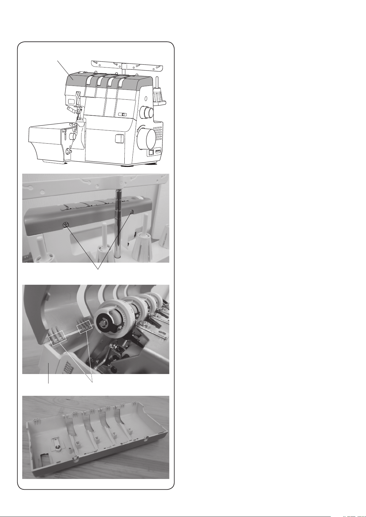
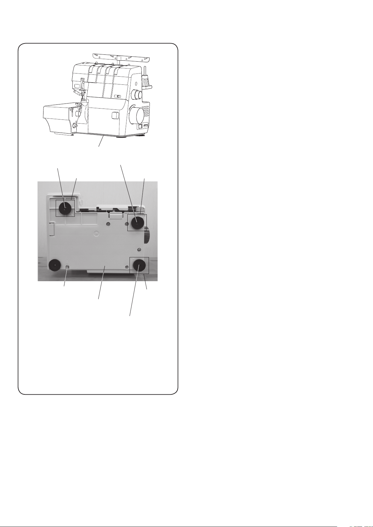
Top cover
To remov e :
1. Remove the setscrews (2 pcs.) on the rear side of the
to p c over.
Setscrew
HookFront cover
2. Release the hooks of the top cover from the front
cov er.
3. Remove the top cover.
To attach:
Follow the above procedure in reverse.
2
Page 5
Face plate
MODEL: AirThread 2000D
Replacing External Parts
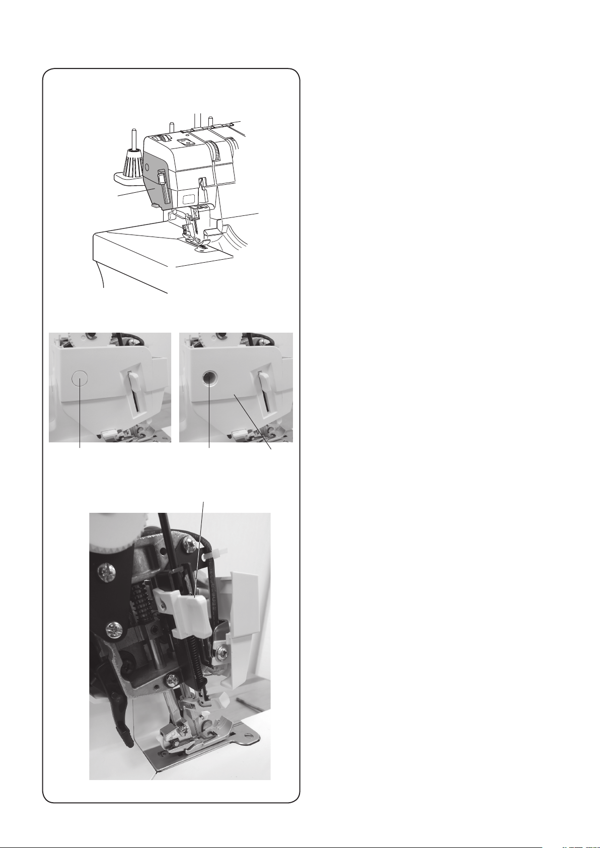
Face plate (1)
Cap Setscrew
Needle treader lever
To remov e :
1. Remove the top cover.
2. Remove the cap.
3. Remove the setscrew.
Face plate
4. Slightly lower the needle threader lever and remove
the face plate.
3
Page 6
Replacing External Parts
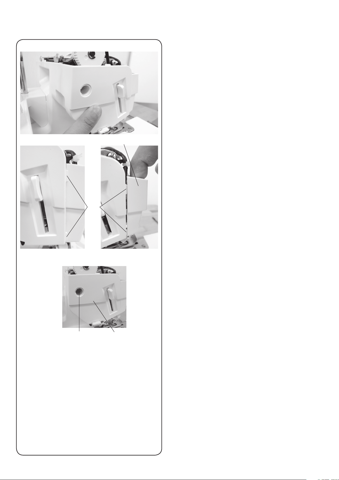
Face plate (2)
To attach:
1. Attach the face plate in place.
Hold the face plate with your finger.
MODEL: AirThread 2000D
Rib
Front cover
2. Pull the front cover lightly and place the ribs into the
inside of the front cover.
3. Tighten the setscrew and attach the cap.
Setscrew
Face plate
4
Page 7
Replacing External Parts
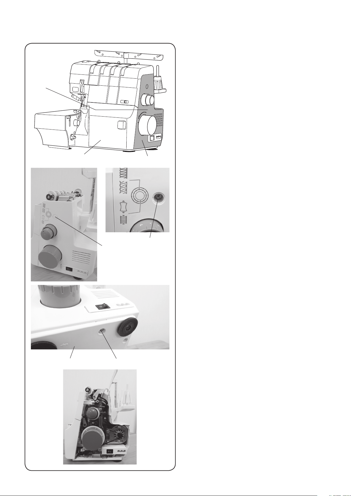
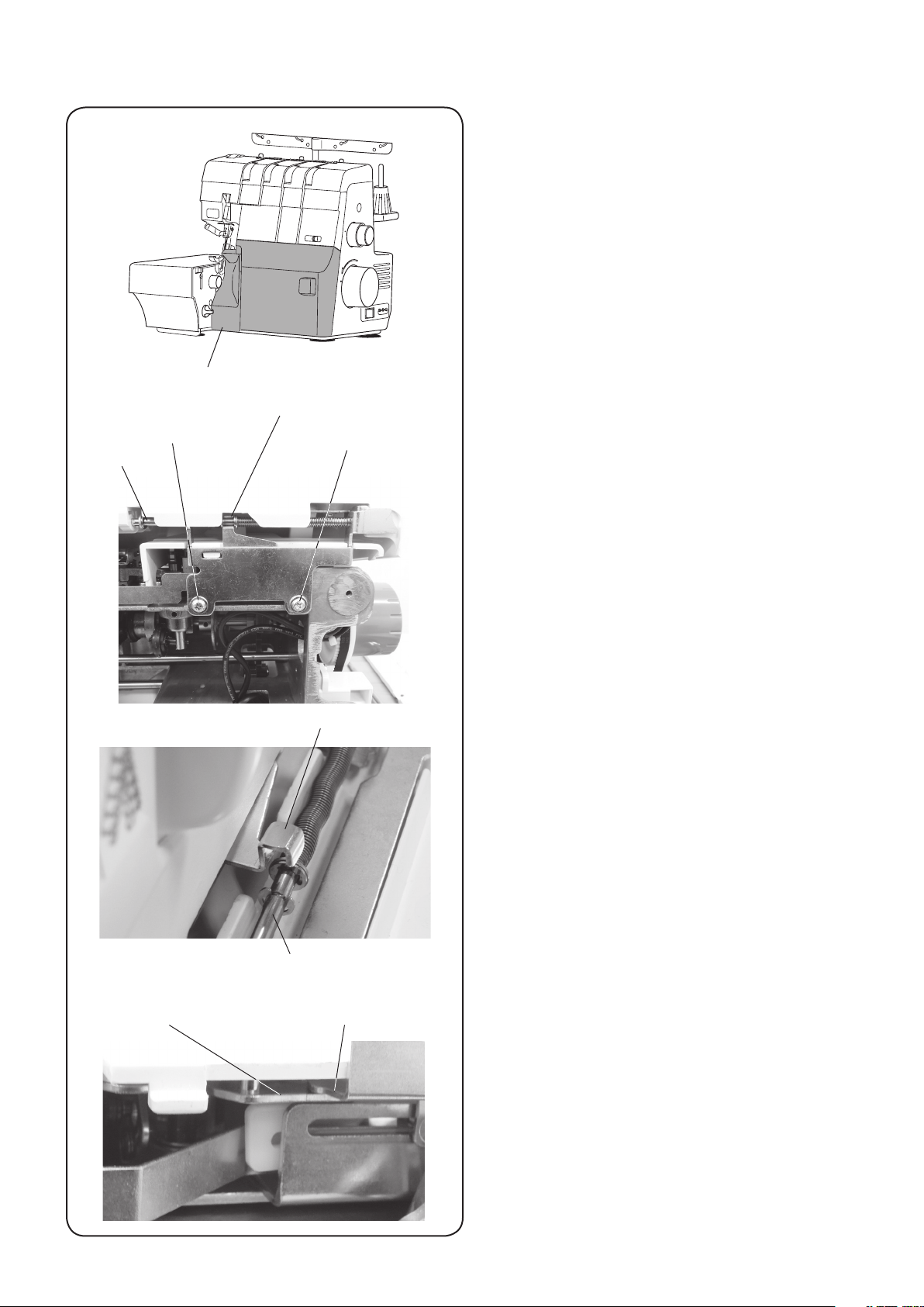
Belt cover
MODEL: AirThread 2000D
Looper cover
Cap
Belt cover
Setscrew A
To remov e :
1. Remove the top cover.
2. Open the looper cover.
3. Remove the cap.
4. Remove the setscrew A.
5. Loosen the setscrew B on the base.
6. Remove the belt cover.
Setscrew BBase plate
7. Close the looper cover.
To attach:
Follow the above procedure in reverse.
5
Page 8
Hinge screw
Rubber sole (unit)
MODEL: AirThread 2000D
Replacing External Parts
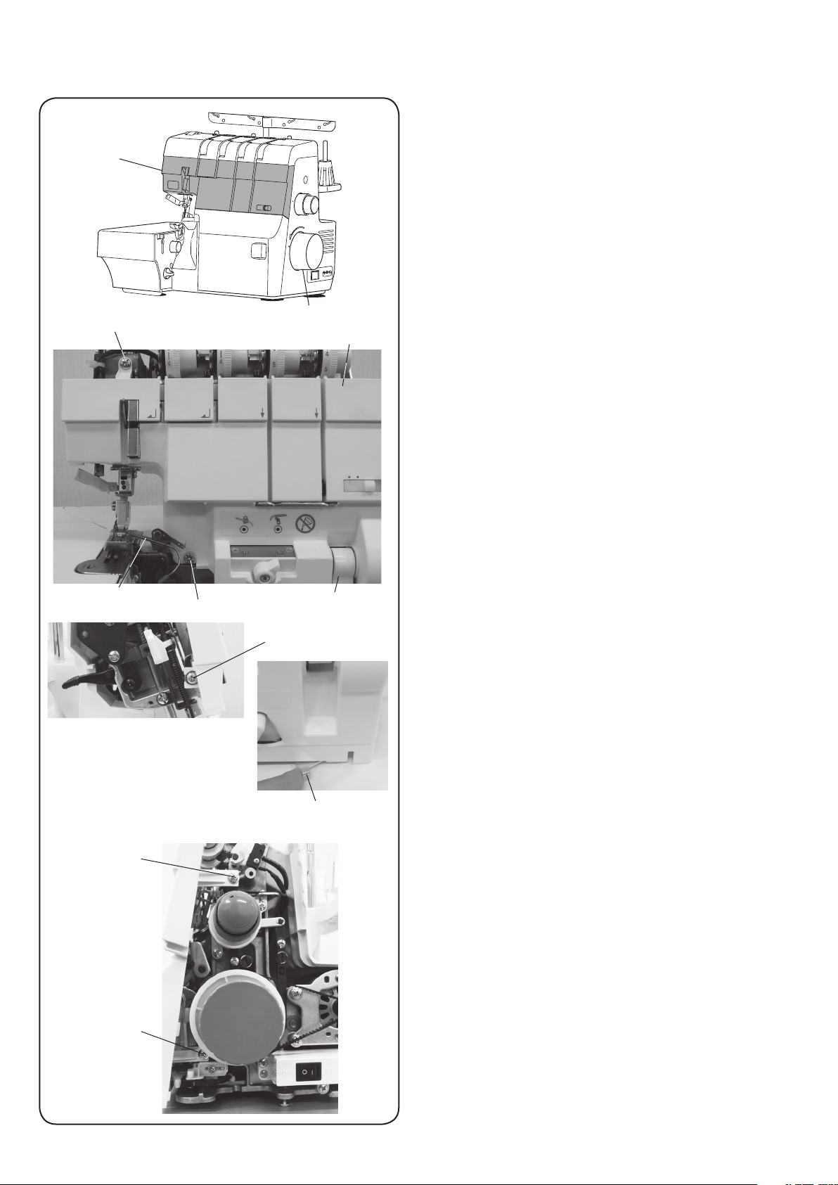
Base plate
Base plate
Hinge screw
Rubber
sole (unit)
To remov e :
1. Open the side cover.
2. Remove the hinge screw (3 pcs.) and remove the
rubber soles (unit).
3. Remove the setscrew.
4. Remove the base plate.
Setscrew
Base plate
To attach:
Follow the above procedure in reverse.
Rubber
sole (unit)
Hinge screw
6
Page 9
Replacing External Parts
Looper cover
MODEL: AirThread 2000D
Looper
cover shaft
Hook of looper cover position detecting arm
Looper cover
Setscrew
Hook of looper cover
position detecting arm
Setscrew
Looper cover shaft
To remov e :
1. Remove the base plate.
2. Remove the setscrews (2 pcs.).
3. Release the hook of looper cover position detecting
arm from the looper cover shaft.
4. Remove the looper cover.
To attach:
1. Set the looper threader switch lever to the
"THREADING" (right side).
Make sure that the looper cover position detecting
arm comes in front of the looper. threader switch
lever connecting lever (shown as the looper cover
position detecting arm on top the looper threader
switch lever connecting lever in the figure).
2. Put the hook of looper cover position detecting arm on
the looper cover shaft.
3. Tighten the setscrews (2 pcs).
4. Attach the base plate.
Looper threader switch lever
connecting lever
Looper cover
position detecting arm
7
Page 10
Replacing External Parts
Front cover
MODEL: AirThread 2000D
Front cover
Setscrew A
To remov e :
1. Remove the top cover, the face plate, the belt cover,
the base plate and the looper cover.
2. Set the upper looper to the lowest position by turning
the handwheel toward you.
Handwheel
Front cover
3. Remove the setscrews A (2 pcs.).
Upper looper
Setscrew C
Setscrew A
Looper cover position detecting arm
Looper threader lever
Setscrew B
4. Loosen the setscrew B.
5. Loosen the setscrews C (2 pcs.).
6. Raise the looper threader lever halfway.
7. Set the looper cover position detecting arm to the right
and remove the front cover.
Setscrew C
To attach:
Follow the above procedure in reverse.
* Make sure that set the front cover into the catch of the
looper cover position detecting arm.
8
Page 11
Side cover
MODEL: AirThread 2000D
Replacing External Parts
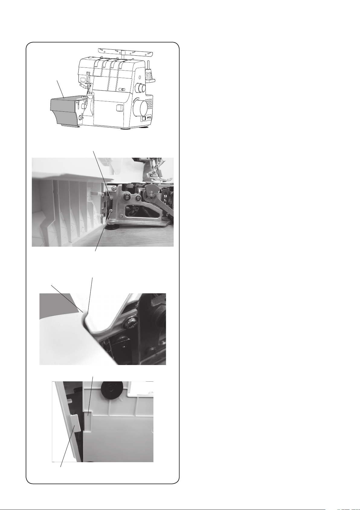
Side cover
Setscrew
To remov e :
1. Open the side cover as far as it will go.
2. Remove the setscrews (2 pcs.).
3. Remove the side cover.
Setscrew
Groove of the rear cover
Edge of the side cover
Recess of the base plate
To attach:
1. Put the edge of the side cover on the groove of the
rear cover and partially tighten the setscrews (2 pcs.).
2. Open and close the side cover adjusting the position
vertically and horizontally. Make sure that there is no
gap with the needle plate, the rear cover or the looper
cover guide.
3. Make sure that the tab of the side cover is engaged
with the recess of the base plate.
4. Tighten the setscrews (2 pcs.).
Tab of the side cover
9
Page 12

Thread guide
base
Rear cover
MODEL: AirThread 2000D
Replacing External Parts
Rear cover
To remov e :
1. Remove the face plate, the belt cover and the side
cov er.
2. Remove the setscrews A (2 pcs.) on the carrying
handle.
Setscrew A
Setscrew B Setscrew B
Setscrew C
3. Remove the setscrews B (2 cps.) from the base.
4. Loosen the setscrew C.
5. Remove the rear cover.
To attach:
Follow the above procedure in reverse.
10
Page 13
MODEL: AirThread 2000D
Mechanical Adjustment
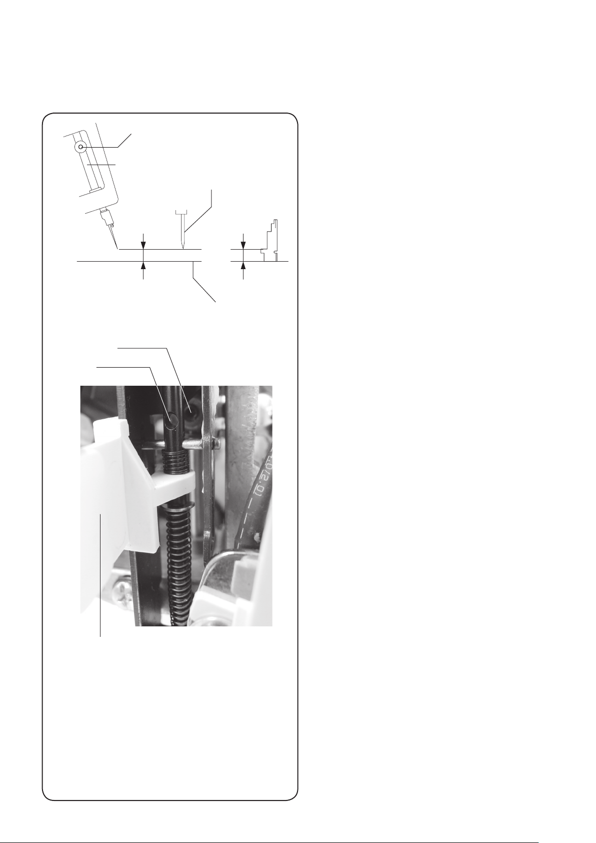
To adjust the needle bar height
The distance between the tip of the right needle (HA x 1SP#14) and the surface of the needle plate should be 11.6 to
12.2 mm when the needle is at the heighest position.
11.6〜12.2 mm
Setscrew
Hole
Setscrew
Needle bar
Right needle
11.9 mm
Surface of needle plate
Gauge
To check:
1. Remove the presser foot (unit).
2. Turn the handwheel toward you to raise the needle
bar at the highest poisition.
3. Use the gauge to check if the distance between the
tip of the right needle and the surface of the needle
plate is 11.6 mm to 12.2 mm.
4. If not, adjust as follows;
To adjust:
1. Remove the top cover and face plate.
2. Lower the needle threader lever to align the hole and
setscrew. Access the setscrew with the hexagonal
wrench (2 mm) through the hole.
3. Loosen the setscrew with the hexagonal wrench (2
mm), and adjust the needle bar height moving the
needle bar up or down. Be careful not to turn the
needle bar while moving it.
Tighten the setscrew after adjustment.
4. Turn the handwheel toward you.
Be sure that the distance between the tip of the right
needle and the needle plate is 11.6 mm to 12.2 mm.
5. Attach the face plate and the top cover.
Needle threader lever
11
Page 14
MODEL: AirThread 2000D
Mechanical Adjustment
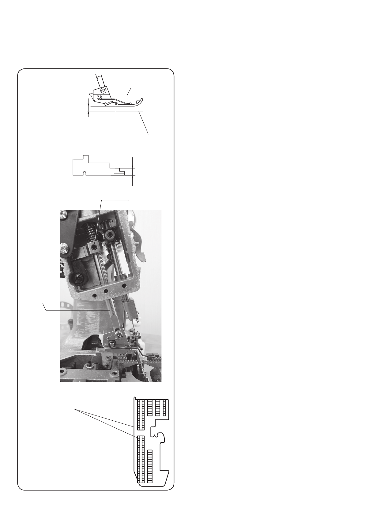
To adjust the presser bar height
The distance between the bottom of the presser foot and the surface of the needle plate should be in the range of 5.2
mm to 5.8 mm when the presser foot is raised.
To check:
Presser foot
5.2 to 5.8 mm
Measure just under the pin
Surface of needle plate
5.5 mm
Gauge
1. Raise the presser foot.
2. Use the gauge to check if the distance between the
bottom of the presser foot and the surface of the
needle plate is 5.2 mm to 5.8 mm.
3. If not, adjust as follows;
Presser bar
Setscrew
To adjust:
1. Remove the top cover and face plate.
2. Loosen the setscrew, and adjust the presser foot bar
height up or down. Be careful not to turn the presser
bar while moving it.
Tighten the setscrew after adjustment.
3. Lower and raise the presser foot again.
Be sure that the distance between the presser foot
and the needle plate is 5.2 to 5.8 mm.
4. Turn the handwheel toward you.
Make sure that the clearance between the needle and
the upper looper is appropriate.
5. Make sure that the presser foot and the feed dog
teeth are parallel.
6. Attach the face plate and the top cover.
The presser foot should be parallel
with the slots for feed dogs.
12
Page 15

MODEL: AirThread 2000D
Mechanical Adjustment
To adjust the feed dog height
The highest position of the feed dog should be 0.9 to 1.1 mm from the surface of the needle plate.
To check:
Presser foot
Feed dog
Measure just under the pin
1 mm
0.9 to 1.1 mm
Feed dog
Surface of needle plate
Gauge
1. Set the presser foot pressure dial to “N”.
2. Set the stitch length dial to “1” and the differential feed
dial to “1.0”.
3. Remove the side cover and rear cover.
4. Lower the presser foot lifter. Turn the handwheel
toward you to raise the feed dog teeth at the highest
position.
5. Push the gauge toward the feed dog teeth and check
the feed dog teeth height.
The feed dog height should be 0.9 to 1.1 mm from the
surface of the needle plate.
If not, adjust as follows;
Setscrew
Main feed dog
Hexagonal bolt (B)
To adjust:
1. Remove the top cover, the belt cover, the face plate
and the rear cover.
2. Loosen the setscrew.
3. If the feed dog is lower than the needle plate, turn the
adjusting screw clockwise.
If the feed dog is higher than the needle plate, turn the
adjusting screw counterclockwise.
After adjustment, tighten the setscrew.
4. Turn the handwheel toward you again and make sure
that the distance feed dog height is appropriate.
Adjusting screw
5. The main feed dog teeth and sub feed dog teeth
should be level. If not, loosen the hexagonal bolt with
a ball point hexagonel wrench and adjust the feed dog
teeth height.
6. Attach the rear cover, belt cover, face plate and the
top cover after adjustment.
Sub feed dog
13
Page 16

MODEL: AirThread 2000D
Mechanical Adjustment
To adjust the differential feed
Set the stitch length dial set to “3” and the differential feed dial to “1.0”.
The gap (a) is the gap between the main feed dog and the sub feed dog when ascending to the level of the needle
plate.
The gap (b) is the gap between the main feed dog and the sub feed dog when descending to the level of the needle
plate.
The difference of the gap (a) and the gap (b) should be 0.1 mm or less.
To adjust:
NOTE:
Adjust the differential feed, after adjusting the feed dog
height (Refer to page 13).
1. Set the stitch length dial to “3” and the differential feed
dial to “1.0”.
2. Open the looper cover and remove the belt cover.
Presser foot (unit)
Gap (a): Feed dog ascending to the level of the needle plate
Gap (b): Feed dog descending to the level of the needle plate
Needle plate
Main feed dog
Stitch length
adjusting pin
Sub feed dog
Setscrew
3. Remove the presser foot (unit).
4. Turn the handwheel toward you to raise the main feed
dog and the sub feed dog until the upper surface
of the feed dog aligns with the upper surface of the
needle plate.
5. Measure the gap (a) between the main feed dog and
the sub feed dog.
6. Turn the handwheel toward you to lower the main
feed dog and the sub feed dog until the upper surface
of the feed dog aligns with the upper surface of the
needle plate.
7. Measure the gap (b) between the main feed dog and
the sub feed dog.
8. If the difference between gaps (a) and (b) is larger
than 0.1 mm, loosen the setscrew and adjust the
differential feed as follows.
⇨ If the gap (a) is larger than the gap (b), turn the
stitch length adjusting pin to the direction where
the differential feed adjusting rod ascends.
⇨ If the gap (b) is larger than the gap (a), turn the
stitch length adjusting pin to the direction where
the differential feed adjusting rod descends.
9. Repeating the steps 4-7, adjust the differential feed
until the difference between gaps (a) and (b) becomes
0.1 mm or less.
10. After adjustment, tighten the setscrew.
11. Attach the presser foot (unit).
12. Attach the belt cover and close the looper cover.
Differential feed
adjusting rod
14
Page 17

MODEL: AirThread 2000D
Mechanical Adjustment
To adjust the stitch length
The actual stitch length should be 3.0 to 3.2 mm (30 to 32 mm for 10 stitches) when the stitch length dial is set to “3”
and the differential feed dial to “1.0”.
To adjust:
Right needle
3.0 to 3.2 mm
30 to 32 mm
Maximum stitch length: 32 mm
Minimum stitch length: 30 mm
Left needle
NOTE:
Adjust the stitch length, after adjusting the feed dog
height and the differential feed (Refer to pages 13 and
14).
1. Set the stitch length dial to “3” and the differential feed
dial to “1.0”.
2. Open the looper cover and remove the belt cover.
3. Sew 11 stitches on a piece of paper and measure the
distance between the first stitch and eleventh stitch
(10-stitch length). If the distance is not 30 to 32 mm,
loosen the setscrew and adjust as follows.
⇨ If the stitch length is longer than 32 mm, turn the
stitch length adjusting pin to the direction where
the differential feed adjusting rod ascends.
⇨ If the stitch length is shorter than 30 mm, turn the
stitch length adjusting pin to the direction where
the differential feed adjusting rod descends.
4. Measure the distance for 10 stitches again. Adjust
until distance becomes 30 to 32 mm.
5. After adjustment, tighten the setscrew
6. Attach the belt cover and close the looper cover.
Stitch length adjusting rod
Setscrew
Stitch length adjusting pin
15
Page 18

MODEL: AirThread 2000D
Mechanical Adjustment
To adjust the timing of the needle and the upper knife
The upper knife timing is the same as that of the needle bar. In fact, when the needle bar is at the highest position, the
upper knife should be also at the highest position.
To check:
1. Turn the handwheel toward you.
2. Check if the upper knife is also at the highest position
when the needle bar is at the highest position.
If not, adjust as follows.
Needle
Highest position
of the upper knife
Highest position
of the needle
Upper knife
(B)
Setscrew
Guide line
Setscrew
(A)
Upper knife drive cam
To adjust:
1. Open the side cover.
2. Set the needle bar to the highest position by turning
the handwheel toward you.
3. Loosen the setscrews (2 pcs.). Turn the upper knife
drive cam to adjust the timing. Tighten the setscrews (2
pcs.).
When the upper knife timing is late:
Turn the upper knife drive cam to the direction (A).
When the upper knife timing is early:
Turn the upper knife drive cam to the direction (B).
NOTE:
Make sure the guide line on the edge surface of the
upper drive cam and the guide line on the main shaft are
matched.
Loosen the setscrews (2 pcs.) and push the upper knife
drive cam to check the guide line on the main shaft.
4. Turn the handwheel toward you to check the timing of
the needle and the upper knife again.
5. Close the side cover.
16
Page 19

MODEL: AirThread 2000D
Mechanical Adjustment
To adjust the position of the upper knife and the lower knife
When the upper knife is at the lowest position, the front lower corner of the upper knife should be 1.0 to 2.0 mm below
the edge of the lower knife.
The distance between the left surface of the lower knife and the front lower corner of the upper knife should be 0.6 to 1.0
mm.
Edge of the lower knife
Edge of the
lower knife
Front lower
corner of the
upper knife
1.0 to 2.0 mm
Edge of the
lower knife
Gauge
Surface of the
needle plate
1.5 mm
Upper knife
0.6 to 1.0 mm
To check:
1. Open the looper cover (unit).
2. Set the upper knife to the lowest position by turning
the handwheel toward you.
3. Check if the front lower corner of the upper knife is 1.0
to 2.0 mm below the edge of the lower knife.
4. Check if the distance between the left surface of the
lower knife and the point of the upper knife is 0.6 to 1.0
mm.
If not, adjust as follows.
To adjust:
1. Open the looper cover (unit).
NOTE:
When replacing the upper knife:
(1) Set the upper knife to the highest position and remove
it.
(2) Attach the new upper knife and partially tighten the
bolt.
2. Set the upper knife to the lowest position by turning
the handwheel toward you.
3. Loosen the bolt.
Adjust the position of the upper knife so that the front
lower corner of the upper knife should be 1.0 to 2.0
mm below the edge of the lower knife.
4. While maintaining the height of the upper knife
unchanged, adjust the position of the upper knife and
the lower knife so that the distance between the left
surface of the lower knife and the point of the upper
knife is 0.6 to 1.0 mm.
Bolt
NOTE:
Do not move the upper knife vertically.
After adjustment, tighten the bolt.
While tightening the bolt, the upper knife may turn
clockwise. After tightening the bolt, re-check if the
distance is 0.6 to 1.0 mm.
Push the upper knife support plate (unit) to the right to
check if the upper knife supporter moves smoothly.
5. Check if the front lower corner of the upper knife is 1.0
to 2.0 mm below the edge of the lower knife.
Check if the distance between the left surface of the
lower knife and the point of the upper knife is 0.6 to 1.0
mm.
6. Close the looper cover.
17
Page 20

Mechanical Adjustment
To replace the lower looper
Upper knife
Bolt
Needle plate
Setscrew A
Looper cover guide
Setscrew B
Upper knife
Upper knife release knob
Chaining finger
Chaining finger switch knob
Lower looper
connecting pipe arm
Setscrew D
Setscrew C
Lower looper base
Lower looper (unit)
Mouth of the
lower looper
pipe
Tube
Lower looper
connecting pipe arm
Lower looper
connecting pipe (unit)
Lower looper
MODEL: AirThread 2000D
To remov e :
1. Open the looper cover (unit) and the side cover (unit).
2. Set the chaining finger switch knob to “R” and lower
the chaining finger.
3. While pressing the upper knife release knob, turn it
clockwise by half a rotation to deactivate the upper
knife.
4. Remove the left needle and the right needle.
5. Remove the presser foot (unit).
6. Remove the setscrew A and remove the needle plate.
7. Remove the setscrews B (2 pcs.) and remove the
looper cover guide.
8. Remove the bolt and remove the upper knife.
9. Set the lower looper to the rightmost position by
turning the handwheel toward you.
10. Remove the setscrew C and the setscrews D (2 pcs.).
Remove the lower looper connecting pipe arm with the
lower looper (unit) and the lower looper connecting
pipe (unit) connected.
NOTE:
Make sure that the looper does not hit the chaining finger.
Remove the lower looper pipe from the mouth of the
lower looper (unit).
11. Remove the tube from the lower looper (unit).
To attach:
1. Insert the mouth of the lower looper (unit) into the
tube and pull the tube upward until the upper end of
the tube aligns with the mouth of the lower looper (unit).
2. Turn the handwheel counterclockwise to move the
lower looper base to the rightmost position.
3. Insert the lower looper connecting pipe into the tube
on the mouth of the lower looper pipe and push the
edge of the lower looper connecting pipe into the
mouth of the lower looper pipe to engage them.
NOTE:
Make sure that the tube is not clipped between the
edge of the looper and the edge of the lower looper
connecting pipe.
4. Partially tighten the setscrews D (2 pcs.) to fix the
lower looper connecting pipe arm.
Aligning the the screw hole of the lower looper with
the screw hole of the lower looper base, artially
tighten the setscrew C to fix the lower looper.
5. Place the U groove of the lower looper height gauge
on the lower looper crank shaft.
Loosen the setscrew C and adjust the height of the
lower looper (unit).
Tighten the setscrew C. (Refer to pages 17 and 18.)
6. Attach the left needle and the right needle.
7. Check the clearance between the needle and the
lower looper, the timing of the needle and the lower
looper, the clearance between the upper looper and
the lower looper, and the timing of the upper looper
and the lower looper (Refer to pages 21, 23, 25 and
27.)
8. Loosen the setscrews D (2 pcs.). Adjust the position
of the mouth of the looper connecting pipe (unit) and
the slide pipe (refer to page 34). Check if the looper
can be threaded the the looper thrader (air) and
tighten the setscrews D (2 pcs.).
9. Tighten the bolt to fix the upper looper. (Refer to page
20).
10. Tighten the setscrews B (2 pcs.) to fix the looper
cover guide.
11. Tighten the setscrew A to fix the needle plate.
12. Attach the presser foot (unit).
13. While pressing the upper knife release knob, turn it
clockwise to activate the upper knife.
14. Close the looper cover and the side cover.
18
Page 21

MODEL: AirThread 2000D
Mechanical Adjustment
To adjust the position of the lower looper (1)
The tip of the lower looper is 65.6 to 65.9 mm from the center of the lower looper crank shaft as shown below.
To check:
1. Open the looper cover and the side cover.
2. While pressing the upper knife release knob, turn it
clockwise by half a rotation to deactivate the upper
Side cover
Upper knife
release knob
To set the upper knife in down position:
Press the
dial
knife.
3. Turn the handwheel counterclockwise to set the lower
looper to the rightmost position.
4. Place the lower looper height gauge to the lower
looper crank shaft as shown.
5. The tip of the lower looper should match with the
guide line of the gauge (65.7 mm).
If not, adjust the lower looper height position (see next
page).
Tip of the lower looper
Setting mark
Guide line
U groove
65.7 mm
Lower looper height gauge
Guide line
Lower looper height gauge
Lower looper crank shaft
19
Page 22

Mechanical Adjustment
To adjust the position of the lower looper (2)
MODEL: AirThread 2000D
Upper knife
Bolt
Needle plate
Setscrew A
Looper cover
guide
Setscrew B
Upper knife
Upper knife release knob
Upper knife
Tip of the
lower looper
Setscrew C
Guide line
To adjust:
1. Open the looper cover and the side cover.
2. While pressing the upper knife release knob, turn it
clockwise by half a rotation to deactivate the upper
knife.
3. Remove the presser foot (unit).
4. Remove the setscrew A and remove the needle plate.
5. Remove the setscrews B (2 pcs.) and remove the
looper cover guide.
6. Remove the bolt and remove the upper knife.
7. Set the lower looper to the rightmost position by
turning the handwheel toward you.
8. Place the U groove of the lower looper height gauge
down on the lower looper crank shaft and hold it.
9. Loosen the setscrew C and move the lower looper
vertically until the tip of the lower looper points at the
guide line of the lower looper height gauge.
10. Tighten the setscrew C.
11. Check the clearance between the needle and the
lower looper, the timing of the needle and the lower
looper, the timing of the upper looper and the lower
looper and the clearance between the upper looper
and the lower looper (Refer to pages 21, 22, 24, 27
and 28.)
12. Tighten the bolt to fix the upper knife.
13. Tighten the setscrews B (2 pcs.) to fix the looper
cover guide.
14. Tighten the setscrew A to fix the needle plate.
15. Attach the presser foot (unit).
16. While pressing the upper knife release knob, turn it
clockwise by half a rotation to activate the upper knife.
17. Close the looper cover and the side cover.
Bolt
Lower looper
crank shaft
Upper knife release knob
Setscrew C
Lower looper
height gauge
Upper knife
20
Page 23

MODEL: AirThread 2000D
Mechanical Adjustment
To adjust the clearance of the needle and the lower looper; and the clearance
of the needle and the needle guard (front) (1)
The standard clearance between the groove of the needle (HAx1 SP #14) and the tip of the lower looper is 0 to 0.05
mm when the needle and the lower looper intersect.
Upper knife
Upper knife release knob
Setscrew B
Needle bar gauge
Groove
Needle
guard (front)
0.05 - 0.25mm
Needle bar gauge
Needle bar
0 - 0.05mm
Lower looper
Needle
guard (rear)
Needle bar lower bushing
Setscrew A
Thumbscrew
Bolt
Bolt
To check:
1. Open the looper cover and the side cover.
2. While pressing the upper knife release knob, turn it
clockwise by half a rotation to deactivate the upper
knife.
3. Remove the left needle.
4. Attach an HAx1 SP #11 needle as the right needle.
5. Turn the handwheel toward you until the tip of the
lower looper comes from the left to the rear groove of
the right needle.
Check if the clearance between the rear groove of the
right needle and the tip of the lower looper is 0 to 0.05
mm when the needle and the lower looper intersect.
7. Attach an HAx1 SP #11 needle as the left needle.
8. Check if the clearance between the rear groove of the
left needle and the tip of the lower looper is 0 to 0.05
mm when the needle and the lower looper intersect.
If not, adjust as follows.
To adjust the clearance between the needle and the
lower looper
1. Open the looper cover (unit) and the side cover (unit).
2. While pressing the upper knife release knob, turn it
clockwise by half a rotation to deactivate the upper
knife.
3. Remove the presser foot (unit).
4. Remove the needle plate.
5. Remove the left needle.
6. Attach an HAx1 SP #11 needle as the right needle.
7. Turn the handwheel toward you until the tip of the
lower looper comes from the left to the rear groove of
the right needle.
8. Check if the clearance between the rear groove of the
right needle and the tip of the lower looper is 0 to 0.05
mm when the needle and the lower looper intersect.
NOTE:
If the needle guard (front) pushes the front surface of the
needle, temporarilly move the needle guard (front) to the
front.
9. Loosen the bolt slightly. Adjust the clearance by
moving the lower looper base. After adjustment,
tighten the bolt.
NOTE:
During adjustment, make sure that the lower looper base
does not turn or the handwheel does not rotate.
Otherwise, the timing of the needle and the lower looper
will be wrong.
Needle bar gauge
10. Attach an HAx1 SP #11 needle as the left needle.
11. Turn the handwheel toward you until the tip of the
lower looper comes from the left to the rear groove of
the left needle.
21
Page 24

MODEL: AirThread 2000D
Mechanical Adjustment
To adjust the clearance of the needle and the lower looper; and the clearance
of the needle and the needle guard (front) (2). To replace the needle guard (front).
The standard clearance between the groove of the needle (HAx1 SP #14) and the tip of the lower looper is 0 to 0.05
mm when the needle and the lower looper intersect.
12. Check if the clearance between the rear groove of the
Setscrew A
Needle bar
lower bushing
Thumbscrew
Needle
bar
Needle bar gauge
left needle and the tip of the lower looper is 0 to 0.05
mm when the needle anTd the lower looper intersect.
13. If the clearance is not correct, leaving the timing left
as is, remove the face plate and the front cover; and
adjust as follows.
14. Place the needle bar gauge on the needle bar . Pull
the needle bar gauge up against the lower surface
of the needle bar lower bushing and tighten the
thumbscrew slightly.
NOTE:
Do not tighten the thumbscrew too much. Otherwise, the
surface fo the needle bar may be damaged.
15. Loosen the setscrew A. Hold the thumbscrew to
prevent the needle bar goes down and adjust the
clearance by turning the needle bar.
16. Tighten the setscrew A.
17. Attach HAx1 SP #14 needles as the left and right
needles.
18. After adjustment, check the timing of the needle and
the lower looper, the timing of the upper looper and
the lower looper and the clearance between the upper
looper and the lower looper (Refer to pages 24, 27
and 28).
To adjust the clearance of the needle and needle
guard (front)
1. Turn the handwheel toward you until the tip of the
lower looper comes from the left to the rear groove of
the needle. Loosen the setscrews B (2 pcs.) and push
the needle guard (front) against the needle slightly so
that the clearance between the rear groove of the left
or right needle and lower looper is 0 to 0.05 mm.
2. Tighten the setscrews B (2 pcs.).
3. Turn the handwheel toward you to check the
clearance again.
To replace the needle guard (front):
1. Remove the setscrew B (2 pcs.).
2. Set the upper knife to the lowest position by turning
the handwheel toward you.
Pulling the feed base upward, remove the needle
guard (front).
Setscrew B
22
Page 25

MODEL: AirThread 2000D
Mechanical Adjustment
To replace the needle guard (front).
To adjust the clearance of the needle and the needle guard (rear).
With the needle deflected by the needle guard (front), the standard clearance between the part of the largest diameter
of the tip of the needle (HAx1 SP #14) and the needle guard (rear) is 0.05 to 0.25 mm.
To replace the needle guard (rear):
To remov e :
Groove
Needle
guard
(front)
Needle guard (rear)
Bolt
Needle bar gauge
0 - 0.05mm
Needle guard (rear)
Upper knife
Upper knife release knob
Lower looper
Remove the bolts (2 pcs.) and remove the needle guard
(rear).
To attach:
Attach the needle guard (rear) and tighten the bolts (2
pcs.).
To adjust:
1. Follow the procedure of “To adjust the clearance of
the needle and needle guard (front)” on the previous
page.
2. Turn the handwheel toward you until the tip of the
lower looper comes from the left to the rear groove
of the needle (with the HAx1 SP #14 needle slightly
deflected by the needle guard (front)). Check the
clearance between the part of the largest diameter of
the tip of the needle and needle guard (rear).
3. If the clearance is not correct, loosen the bolts (2
pcs.). Adjust the position of the needle guard (rear)
and tighten the bolts (2 pcs.).
4. Attach the face plate and the front cover.
5. Attach the needle plate.
6. Attach the presser foot (unit).
7. While pressing the upper knife release knob, turn it
clockwise by half a rotation to activate the upper knife.
8. Close the looper cover and the side cover.
0.05 - 0.25mm
23
Page 26

MODEL: AirThread 2000D
Mechanical Adjustment
To adjust the timing of the needle and the lower looper
When the needle comes up 3.4 to 3.8 mm from the lowest position, the tip of the lower looper comes to the left side of
the right needle (HAx1 SP #14).
Upper knife
Upper knife release knob
Needle bar lower bushing
Thumbscrew
Timing gauge
Needle bar gauge
Needle bar gauge
Lowest
needle
position
Timing gauge
Needle bar lower bushing
Thumbscrew
Needle bar gauge
Bolt
To adjust:
1. Remove the face plate.
2. Open the looper cover and the side cover.
3. While pressing the upper knife release knob, turn it
clockwise by half a rotation to deactivate the upper
knife.
4. Remove the presser foot (unit).
5. Remove the needle plate.
6. Remove the left needle.
7. Attach an HAx1 SP #14 needle as the right needle.
8. Set the needle bar to the lowest position by turning
the handwheel toward you.
9. Place the timing gauge at the base of the bushing.
than place the needle bar gauge directry under the
timing gauge.
Tighten needle bar gauge thumbscrew lightly.
NOTE:
Make sure that there is no gap between the needle bar
lower bushing and the timing gauge or between the
timing gauge and the needle bar guage. Do not tighten
the thumbscrew too much. Otherwise, the surface fo the
needle bar may be damaged.
10. Remove the timing gauge. Turn the handwheel toward
you to raise the needle bar until the needle bar gauge
touches the needle bar lower bushing.
11. Loosen the bolt slightly. Turn the lower looper base to
the left or right until the tip of the lower looper comes
to the left side of the right needle.
NOTE:
Make sure that the clearance between the tip of the lower
looper and rear groove of the right needle is 0 to 0.05
mm, with the needle deflected by the needle guard (front).
12. Loosen the bolt and remove the needle bar guage.
13. Check the timing of the upper looper and the lower
looper and the clearance between the upper looper
and the lower looper (Refer to pages 27 and 28).
14. Attach the left needle.
15. Attach the needle plate.
16. Attach the presser foot (unit).
17. While pressing the upper knife release knob, turn it
clockwise by half a rotation to activate the upper knife.
18. Close the looper cover and side cover.
19. Attach the face plate.
Upper knife
Upper knife release knob
24
Page 27

MODEL: AirThread 2000D
Mechanical Adjustment
To replace the upper looper and to adjust the position of the tip of the upper
looper
To replace the upper looper
To remov e :
1. Open the looper cover and the side cover.
2. While pressing the upper knife release knob, turn it
clockwise by half a rotation to deactivate the upper knife.
3. Set the chaining finger switch knob to R.
4. Remove the left and right needles.
5. Remove the presser foot (unit).
6. Remove the needle plate.
7. Set the needle bar to the highest position by turning the
handwheel toward you.
8. Loosen the setscrew.
9. Pull the tube upward until the lower end of the tube aligns
with the lower end of the mouth of the upper looper.
10. Pulling up the upper looper, remove the mouth of the
upper looper from the upper looper connecting pipe.
11. Remove the spreader and attach it to the new upper
lo o p er.
To attach:
1. Insert the mouth of the upper looper into the tube and pull
the tube upward until the lower end of the tube aligns with
the lower end of the mouth of the upper looper.
2. Set the needle bar to the highest position by turning the
handwheel toward you.
3. Inserting the upper looper pin into the side hole of the upper
looper, insert the upper looper pipe into the mouth of the
upper looper.
4. Partially tighten the setscrew.
5. Pull the tube downward until the upper end of the tube
aligns with the mouth of the upper looper.
To adjust the position of the tip of the upper looper:
1. Set the upper looper to the leftmost position by turning the
handwheel toward you.
2. Loosen the setscrew. When the upper looper moves down
from the leftmost position, place the upper looper tip gauge
on the upper looper shaft guiding the gauge against the
lower surface of the upper looper. Slightly turn the gauge to
the direction of arrow until the bulge of the gauge touches
the upper looper pin.
3. Move the upper looper to the right or the left to adjust the
position of the upper looper so that the tip of the upper
looper comes to the guide of the upper looper tip gauge.
Partially tighten the setscrew and remove the upper looper
tip gauge.
4. Turn the handwheel toward you to adjust the clearance
between the tip of the upper looper and the rear surface
of the lower looper; and tighten the setscrew (refer to “To
adjust the clearance between the upper looper and the
lower looper”) (Refer to page 28).
5. Attach the needle plate.
6. Attach the presser foot (unit).
7. Attach the left and right needles.
8. While pressing the upper knife release knob, turn it
clockwise by half a rotation to activate the upper knife.
9. Close the looper cover and the side cover.
10. After adjustment, check the leftmost position of the upper
looper, the timing of the upper looper and lower looper, and
the clearance between the needle and the upper looper
(Refer to pages 26, 27 and 29).
Upper knife
Upper knife release knob
Upper looper body
Upper looper
connecting pipe
Mouth of the
upper looper
Upper looper
shaft
Upper looper tip gauge
Upper looper tip
Guide line
Upper
looper shaft
Upper looper
Setscrew
Upper looper pin
Tube
Needle plate setting knob: R
Spreader
Lower edge of
the upper looper
Bulge
Upper looper pin
25
Page 28

MODEL: AirThread 2000D
Mechanical Adjustment
To adjust the leftmost position of the upper looper
When the upper looper is at the leftmost position, the distance (front view) between the center of right needle and the
tip of the upper looper should be 7.8 to 8.2 mm.
To check:
Spreader
NOTE:
Adjust the position of the tip of the upper looper, after
Lower edge of
the upper looper
adjusting the position of the tip of the upper looper (Refer
to page 25).
Upper looper driving arm
Gauge
Gauge
8mm
Upper looper shaft
Upper surface of
the upper looper
shaft guide
Setscrew
Right needle
1. Remove the front cover.
2. Remove the left needle.
3. Attach an HAx1 SP #14 needle as the right needle.
4. Set the upper looper to the leftmost position by turning
the handwheel toward you.
5. Place the plate gauge on the tip of the upper looper
and the left side of the right needle (as shown in the
figure) to check the position of the tip of the upper
looper.
If adjustment is required, adjust the position as
follows.
To adjust:
1. Loosen the setscrews (2 pcs.). Adjust the position of
the tip of the upper looper by moving the upper looper
driving arm up or down.
2. Make sure not to move the upper looper driving arm
to the rear or the front. Otherwise, the upper looper
shaft may not move smoothly. Move the upper looper
driving arm slightly up and down to check it moves
smoothly; and partially tighten the setscrew.
3. Check the timing of the upper looper and the lower
looper, and the clearance between the needle and the
upper looper (Refer to pages 27 and 28.)
4. Tighten the setscrews (2 pcs).
5. Attach the left needle.
6. Attach the front cover. (Attach the other exterior
parts.)
Upper looper tip
26
Page 29

MODEL: AirThread 2000D
Mechanical Adjustment
To adjust the timing of the upper looper and the lower looper
When the lower looper moves to the right from the leftmost position and the tip of the upper looper meets the lower
edge of the lower looper as shown in the Fig. 1, the standard distance (front view) between the tip of upper looper and
the tip of the lower looper is 3.5 to 4.1 mm.
To adjust:
3.8 mm
Fig. 1
Upper looper tip
Fig. 2
Fig. 3
Gauge
Lower looper tip
3.5 to 4.1 mm
Upper looper cam
Setscrew
(A)
NOTE:
Adjust adjusting the timing of the needle and the lower
looper, the position of the tip of the upper looper and the
leftmost position of the upper looper, and the timing of
the upper looper and the lower looper (Refer to pages 24,
25 and 27).
1. Open the side cover and remove the base plate.
2. While pressing the upper knife release knob, turn it
clockwise by half a rotation to deactivate the upper
knife.
3. Turn the handwheel toward you to set the upper
looper and the lower looper to the phase shown in
the Fig. 1 (when the lower looper moves from left to
right and the upper looper moves upward). Turn the
spreader to the right.
4. Place the plate gauge on the lower looper and check
the position of the tip of the upper looper.
5. If the position of the tip of the upper looper is not
correct, loosen the setscrews (2 pcs.) and adjust the
position by turning the upper looper cam.
⇨ If the timing of the upper looper is early (as shown
in Fig. 2), turn the upper looper cam in the direction
(A) and tighten the setscrews (2 pcs.).
⇨ If the timing of the upper looper is late (as shown in
Fig. 3), turn the upper looper cam in the direction (B)
and tighten the setscrews (2 pcs.).
6. After adjustment, check the clearance between
the needle and the upper looper and the clearance
between the upper looper and the lower looper (Refer
to pages 26 and 29.)
7. Attach the base plate and close the side cover
8. While pressing the upper knife release knob, turn it
clockwise by half a rotation to activate the upper knife.
(B)
Setscrew
27
Page 30

MODEL: AirThread 2000D
Mechanical Adjustment
To adjust the clearance of the upper looper and the lower looper
When the lower looper moves to the right from the leftmost position, the upper looper moves upward from the lowest
position, and the tip of the upper looper comes behind the rear surface of the lower looper as shown in the figure, the
standard distance between the tip of upper looper and the rear surface of the lower looper is 0 to 0.1 mm.
To adjust:
Lower looper
0 to 0.1mm
Lower looper
Upper looper
Upper looper
Setscrew
NOTE:
Adjust adjusting the position of the tip of the upper
looper and timing of the upper looper and lower looper,
the timing of the needle and the lower looper, and the
clearance of the upper looper and the lower looper (Refer
to pages 25, 27 and 28).
1. Open the looper cover.
2. While pressing the upper knife release knob, turn it
clockwise by half a rotation to deactivate the upper
knife.
3. Turning the handwheel toward you so that the upper
looper intersects the lower looper.
4. Loosen the setscrew. Adjust the clearance between
the tip of the upper looper and the rear surface of the
lower looper by moving the upper looper to the front
or the rear,
NOTE:
Do not move the upper looper to the right or the left.
Otherwise, the timing will be wrong.
Lower looper
5. Partially tighten the setscrew and check the position of
the tip of the upper looper and the clearance between
the needle and the upper looper (Refer to pages 25
and 29.)
6. Tighten the setscrew.
7. Close the looper cover.
8. While pressing the upper knife release knob, turn it
clockwise by half a rotation to activate the upper knife.
Upper looper
28
Page 31

MODEL: AirThread 2000D
Mechanical Adjustment
To adjust the clearance between the needle and the upper looper
When the upper looper meets the right needle or the left needle, each clearance should be -0.05 to +0.05 mm.
To check:
Rear bulge of the upper looper
1. Turn the handwheel toward you until the upper looper
moves to the right from the leftmost position, the
needle bar goes down from the highest position and
the rear bulge of the upper looper intersects the left
needle and right needle.
2. Check if the clearance between the rear bulge of the
upper looper and the left needle or the right needle is
-0.05 to 0.05 mm.
Needle
Lower looper
Setscrew
Upper looper
NOTE:
Adjust after adjusting the timing of the needle and the
lower looper, the position of the tip of the upper looper
and the leftmost position of the upper looper, the timing of
the upper looper and the lower looper and the clearance
between the upper looper and the lower looper, and the
clearance between the needle and the upper looper (Refer
to pages 24 to 29.)
1. Open the looper cover.
2. Turn the handwheel toward you until the upper lower
moves to the right from the leftmost positon, the
needle bar moves upward from the lowest point and
the rear bulge of the upper looper intersects the left
needle or the right needle.
3. Loosen the setscrew and adjust the clearance
between the needle and the rear bulge of the upper
looper by moving the upper looper to the front or the
re a r.
NOTE:
Do not move the upper looper to the right or the left.
Otherwise, the timing will be wrong.
4. Partially tighten the setscrew and check the position
of the tip of the upper looper, and the clearance of the
upper looper and the lower looper (Refer to pages 25
and 28).
5. Tighten the setscrew.
6. Close the looper cover.
29
Page 32

MODEL: AirThread 2000D
Mechanical Adjustment
To adjust the position of the chaining finger
The standard distance between the side edge of the needle plate and the left edge of the chaining finger is 0.2 mm.
The side edge of the needle plate should not interfere with the left edge of the chaining finger. When setting the chaining
finger switch knob to “S”, the tip of the chaining finder should align with the point of the needles on the needle plate.
Upper knife release knob
Chaining finger switch
knob: R
Upper knife
Setscrew
Chaining finger switch
knob: S
To adjust:
1. Open the side cover.
2. Remove the presser foot (unit).
3. While pressing the upper knife release knob, turn it
clockwise by half a rotation to deactivate the upper
knife.
4. Set the chaining finger switch knob to “S”.
5. Loosen the setscrews (2 pcs.). Adjust the position of
the chaining finger by moving the chaining finger set
plate. Tighten the setscrews (2 pcs.).
6. Move the chaining finger switch knob to check if the
chaining finger moves smoothly.
7. Attach the presser foot (unit).
8. While pressing the upper knife release knob, turn it
clockwise by half a rotation to activate the upper knife.
9. Close the side cover.
Side edge of
the needle plate
Upper knife
Chaining finger switch set plate
Left edge of
the chaining finger
Upper knife release knob
30
Page 33

Mechanical Adjustment
To adjust the thread tensions
Use a standard thread #50. Do not pass the thread through the top cover thread guide.
Standard tension:
Left needle: Tension dial set to 3, 30-40 gf, Tension dial set to 9, 80 gf or more
Right needle: Tension dial set to 3, 15-19 gf, Tension dial set to 9, 50 gf or more
Upper looper: Tension dial set to 3, 9-13 gf, Tension dial set to 9, 30 gf or more
Lower looper: Tension dial set to 3, 18-22 gf, Tension dial set to 9, 55 gf or more
To adjust:
1. Use a standard thread to check the tension.
2. If the thread tension is not correct, turn the tension
dial so that the thread tension becomes the value
represented by “3” of the dial (ignore the real number
on the dial).
3. Remove the top cover.
4. Raise and hold the adjusting plate with a screwdriver.
Turn the dial to match the position of “3” with the notch
(position of the setting mark on the top cover).
5. Check the thread tension again. Repeat the procedure
of steps 2 and 4 until the thread tension becomes
correct.
6. Attach the top cover.
MODEL: AirThread 2000D
Thread tension
plate
Notch of
the thread
tension plate
Thread tension dial
Notch of
the thread
tension plate
Turn the dial to the
direction (A)
to loosen
the tension
To pull the thread to this direction
Thread
Holding the adjusting plate
raised with a screwdriver,
turn the dial.
Adjusting
0
plate
1
Turn the dial to the
direction (B)
to tighten
2
31
Page 34

Mechanical Adjustment
To adjust the pre-tension
Use a standard thread #50 to check the tension of the looper pre-tension.
Standard tension:
Lower looper pre-tension setting slider set to “STD.”: 1 gf or less.
Lower looper pre-tension setting slider set to “TIGHT”: 45-55 gf.
To check:
SlitSlit
1. Open the looper cover and remove the belt cover.
2. Check the tension of the lower looper pre-tension with
the standard thread.
3. If the thread tension is not correct, adjust the tension
by inserting a screwdriver in the slit of the thread
tension shaft and turning it.
⇨ If the tension is too tight, turn the thread tension
shaft counterclockwise.
⇨ If the tension is too loose, turn the thread tension
shaft clockwise.
4. Check the thread tension again. Repeat the procedure
of step 3 until the thread tension becomes correct.
5. Attach the belt cover and close the looper cover.
MODEL: AirThread 2000D
32
Page 35

Mechanical Adjustment
To adjust the needle threader
The hook of the needle threader should come through the eye of the needle.
MODEL: AirThread 2000D
Threader plate (unit)
Needle threader
switch lever
Setscrew B
Threader lever
Hook
Setscrew A
Needle threader
switch lever set
plate
Threader plate (unit)
Needle
Needle
hole
To check:
1. Attach HAx1 SP #11 needles as the left and right
needles.
2. Turn the handwheel toward you to match the mark of
the belt cover with the mark of the handwheel.
3. Lower the needle threader lever.
4. Loosen the setscrew A. Move the needle threader
switch lever set plate vertically so that the hook comes
through eye of the left needle or the right needle.
5. Loosen the setscrew B. Move the needle threader
switch lever set plate horizontally so that the hook
comes through eye of the left needle or the right
needle.
6. Loosen the setscrews C (2 pcs.). Adjust the position
of the
threader shaft guide plate by moving it to the front or
the rear so that the hook comes out from the hole of
the left and right needles.
(When the hook is lowered, the upper ribs above the
hook should touch the rear side of the needle slightly.)
7. Check if the needle threader works correctly.
Setscrew C
Setscrew C
Threader shaft guide plate
When the hook is
lowered, the upper ribs
above the hook should
touch the rear side of
the needle slightly
33
Page 36

MODEL: AirThread 2000D
Mechanical Adjustment
To adjust the position the looper thread take-up lever
When the upper looper is in the lowest position, the looper thread take-up lever should be upright.
In case the position of looper take-up lever cannot be adjusted completely after adjusting the looper threader (air),
adjustment of the looper threader (air) is preferable to adjustment of the looper take-up lever.
To check:
1. Open the looper cover.
2. Turn the handwheel toward you to set the upper
looper to the lowest position.
3. Loosen the setscrew. Turn the looper thread take-up
lever. Tighten the setscrew.
4. Check if you can thread the upper looper using the
looper threader.
(Refer to “To adjust the looper threader (air)” on pages
35 and 36.)
5. Close the looper cover.
Setscrew
Looper thread
take-up lever
34
Page 37

MODEL: AirThread 2000D
Mechanical Adjustment
To adjust the looper threader (air) (1)
When threading the upper looper or the lower looper with a standard thread #60, a thread of 30 mm or longer should come out
from the hole of the looper.
For threading with the looper threader (air), see the instruction manual.
Thread
Tip of the upper looper
Looper
threading wire
Slide pipe
Joint of the looper
connecting pipe
Failure
Upper looper
Tip of the lower looper
Looper threader
switch lever:
SEWING
Looper
threader lever
Threading hole
Lower looper
Thread
Looper threader
lever
Looper threader
switch lever:
THREADING
To c h e ck :
NOTE:
For checking the looper threader, do not use threads thicker
than #60, loosely twisted threads, special threads, moist or wet
threads. If the thread end is fluffed, trim it.
When you thread the looper with the looper threader (air), the
thread may be stained with grease or oil. Do not use it again.
Do not remove the thread pulling it from the threading hole.
1. Open the looper cover.
2. Thread the upper looper and the lower looper with the
looper threader (air).
If the thread does not come out from the hole of the looper
or the thread of less than 30 mm comes out of the hole of
the looper, remove both threads.
3. Set the looper threader switch lever to “SEWING”.
4. With the looper threader (air), thread the looper of which
thread does not come out from the hole correctly in the
step 2.
⇨ (a) If the thread of 100 mm or longer comes out:
Defect in the looper
⇨ (b) If the thread of less than 100 mm comes out:
Defect in the looper threader
5. Case (a)
5-1 There can be lint or objects stuck in the pipe of the looper.
Insert the looper threading wire into the mouth of the looper
connecting pipe to the tip of the looper to clean the pipe.
(Refer to page 53 in the instruction manual.)
5-2 Repeat the procedure from step 2.
5-3 If the problem is not solved yet, the slide pipe and the
looper connecting pipe may not be coaxial or straight.
6. Remove the top cover, the face plate, the belt cover, the
base plate, the looper cover and the front cover. Open the
side cover.
* To adjust:
・ Set the looper threader switch lever to “THREADING”
position.
Turn the handwheel toward you slowly until it clicks.
・ The slide pipe comes to the left and it is engaged with the
mouth of the looper connecting pige. Return the looper
threader switch lever to “SEWING” position to disengage
the slide pipe to the right.
・ Set the looper threader switch lever to “THREADING”
position and “SEWING” position slowly to check if the slide
pipe and the looper connecting pipe are getting coaxial and
straight.
Mouth of the upper
looper connecting pipe
Setscrews A
Mouth
Arm of the lower
looper connecting pipe
Setscrew B
Slide pipe
NOTE:
The mouth of the looper connecting pipe is conical. If the slide
pipe and the looper connecting pipe are not coaxial or straight,
the slide pipe will be delicately moving to the coaxial position.
[Upper looper]
・ Adjust the position of the upper looper connecting pipe
supporter after adjusting the position of the looper take-up
lever.
・ Loosen the setscrews A (2 pcs.) of the upper looper
connecting pipe supporter slightly.
Adjust the position of the upper looper connecting pipe
supporter to the opposition direction to which the slide pipe
moves at engagement.
・ Tighten the setscrews A (2 pcs.).
・ Thread the upper looper with the looper threader and check
the length of the thread coming out from the hole of the
upper looper tip.
35
Page 38

MODEL: AirThread 2000D
Mechanical Adjustment
To adjust the looper threader (air) (2)
When threading the upper looper or the lower looper with a standard thread #60, the thread of 30 mm or longer should
come out from the hole of the looper.
Threading hole
Slide pipe
Looper
threading wire
Looper threader (air) (unit)
Setscrews C
Cover
detecting base
Setscrew D
Setscrew DSetscrew D
Looper
threading wire
[Lower looper]
・ Loosen the setscrews B (2 pcs.) of the lower looper
connecting pipe supporter slightly.
Adjust the position of the upper looper connecting pipe
supporter to the opposition direction to which the slide pipe
moves at engagement.
・ Tighten the setscrews B (2 pcs.).
・ Thread the lower looper with the looper threader and check
the length of the thread coming out from the hole of the
lower looper tip.
7. Case (b) on the previous page
7-1 There can be lint or objects stuck in the pipe of the
looper.
Insert the looper threading wire into the mouth of the
looper connecting pipe to the tip of the looper to clean
the pipe. (Refer to page 53 in the instruction manual.)
7-2 Repeat the procedure from step 2.
7-3 If the problem is not solved yet, the looper threader
device (air) (unit) may be defective. Replace the
looper threader device (air) (unit).
7-4 To replace the looper threader device (air) (unit)
NOTE:
Set the looper threader switch lever is set to “SEWING”
(the slide pipe is disengaged from the looper connecting
pipe and set the upper looper to the lowest position for
attaching or removing the looper threader device (air).
・ Set the looper threader switch lever to “SEWING”
position.
・ Remove the front cover.
・ Remove the setscrews C (2 pcs.). Separate the cover
detecting base (unit) from the threader base (it cannot
be completely removed).
・ Remove the setscrews D (3 pcs.) and remove the
looper thrader device (air) (unit).
・ Placing the lower edge of the new looper thrader
device (air) (unit) behind the cover detecting base
(unit), fix it on the arm by tightening the setscrews D (3
pcs.).
・ Attach the cover detecting base (unit) and tighten the
setscrews C (2 pcs.).
・ Check and adjust the position of the slide pipe and
the looper connecting pipe (refer to the instructions of
“* To adjust:” in the clause 6.
8. Attach the front cover. (Attach the other exterior
parts.)
9. Close the looper cover.
36
Page 39

MODEL: AirThread 2000D
Mechanical Adjustment
To adjust the height of the rubber sole (rear left)
The adjustable rubber sole (rear left) is 0.6 mm higher (above the level) than the other 3 rubber soles.
To check:
1. Place the machine with the rear cover down.
2. Insert a screwdriver into the slit of the adjusting screw
of the real left rubber sole. Tighten the screw and
loosen the screw by a quarter rotation.
The height should be 0.6 mm above the level of the
other 3 rubber soles.
3. Place the machine upright. Check if the 4 rubber soles
are level. Check the vibration of the machine while
running.
Adjusting screw
37
Page 40

Replacing External Parts
To replace the machine socket
Setscrew A
Setscrew A
Connector (LED)
MODEL: AirThread 2000D
To remov e :
1. Remove the belt cover and the rear cover.
2. Remove the setscrews A (2 pcs.). Pull the machine
socket by the allowance length of the cable, and
remove the connector (LED).
3. Remove the setscrew B (2 pcs.) and remove the
cable.
For removing and attaching each part, refer to the
instructions in the related section.
To attach:
1. Connect the cord of the replaced part to the machine
socket unit.
2. Tight the setscrews B (2 pcs.) to fix the machine
socket (unit).
3. Insert the machine socket (unit) under the motor (unit)
and insert the connector (LED).
4. Tighten the setscrews A (2 pcs.) to fix the machine
socket unit on the arm.
5. Attach the belt cover and the rear cover.
Machine socket cover
Setscrew B Machine socket
Setscrew B
38
Page 41

Replacing External Parts
To replacing the motor (1)
MODEL: AirThread 2000D
To remov e :
1. Remove the belt cover, the rear cover and the
machine socket (unit).
2. Remove the setscrews A (2 pcs.).
3. Remove the motor.
4. Remove the setscrews B (2 pcs.).
5. Remove the machine socket cover.
6. Remove the nuts.
7. Remove the motor terminals from the machine socket.
Setscrew B
Setscrew A
Machine socket cover
Machine socket
Motor terminals
Belt
Motor pulley
Setscrew B
Machine socket cover
To attach:
1. Connect the motor terminals to the machine socket.
2. Tighten the nuts.
3. Attach the machine socket cover to the machine
socket.
4. Tighten the setscrews B (2 pcs).
5. Tighten the setscrews A (2 pcs.) to fix the motor on
the arm.
Machine socket
Nut
Motor (unit)
39
Page 42

To replace the motor (2)
MODEL: AirThread 2000D
Replacing External Parts
To attach:
Follow the procedure on the previous page.
6. Attach the motor belt on the belt wheel and the motor
pulley. Check if the motor belt tension is correct.
*Standard tension*
The correct motor belt tension is when the deflection of
motor belt is about 5 - 6 mm, while pushing the motor belt
by finger with a 300 gf.
7. Loosen the setscrews A (2 pcs.) and adjust the
position of the motor to adjust the motor belt tension.
8. Attach the belt cover, the rear cover and the machine
socket (unit).
Setscrew A Motor pulleyMotor belt
Deflection 5 - 6 mm
300 gf
40
Page 43

To replace the LED
Replacing External Parts
To remov e :
1. Remove the top cover, the face plate, the belt cover,
Connector (LED)
the front cover, the rear cover and the machine socket
(unit).
2. Remove the connector (LED) from the machine socket
(unit).
3. Open the LED holder and remove the LED.
4. Cut the cord binders (2 pcs.and remove the LED cord
from the rear cord guide.
MODEL: AirThread 2000D
Cord binder
LED holder
Cord binder
To attach:
1. Insert the LED in the LED holder and close the hook.
2. Insert the LED cord in the rear cord guide.
3. Insert the LED connector in the machine socket (unit).
4. Fix the LED cord on the arm with the cord binders (2
pcs.).
5. Place the machine socket (unit) under the motor (unit).
6. Attach the machine socket (unit).
7. Attach the top cover, the face plate, the belt cover, the
front cover and the rear cover.
Cord guide
Motor
LED cord
41
Page 44

Replacing External Parts
To change the micro switch
(covers and looper threader switch lever)
Switch set plate 1
Setscrew A
Relay cable RF
Micro switch
Relay cable FF
MODEL: AirThread 2000D
To remov e :
1. Remove the belt cover.
2. Remove the setscrew A and remove the switch set
pla te 1.
3. Remove the setscrew B and remove the micro switch.
4. Remove the terminals from the relay cable RF (unit)
and the relay cable FF (unit).
To attach:
1. Insert the terminals into the relay cable RF (unit) and
the relay cable FF (unit).
2. Tighten the setscrew B to fix the micro switch to the
switch set plate 1.
3. Partially tighten the setscrew A to fix the switch set
plate 1 to the cover detecting base.
4. Close the side cover.
5. Adjust the position of the switch set plate 1 so that the
micro switch is set ON or OFF when the looper cover
is opened or closed.
6. Attach the belt cover.
Setscrew B
Cover positipn detecting base
42
Page 45

Replacing External Parts
To change the micro switch (presser foot lifter)
To remov e :
Micro switch
Thread tension set plate
Setscrew B
Relay cable FF
Switch set plate 2
Setscrew A
Relay cable RF
1. Remove the belt cover.
2. Remove the setscrew A and remove the switch set
plate 2.
3. Remove the setscrew B and remove the micro switch.
4. Remove the terminals from the relay cable RF (unit)
and the relay cable FF (unit).
To attach:
1. Insert the terminals into the relay cable RF (unit) and
the relay cable FF (unit).
2. Tighten the setscrew B to fix the micro switch to the
switch set plate 2.
3. Partially tighten the setscrew A to fix the switch set
plate 2 to the thread tension set plate.
4. Adjust the position of the switch set plate 2 so that the
micro switch is set ON or OFF when the presser foot
lifter is lowered or raised. Tighten the setscrew A.
5. Attach the belt cover.
MODEL: AirThread 2000D
43
 Loading...