

Janome 990D Service Manual

SERVICE MANUAL
&
PARTS LIST
990D

TO CHANGE THE FACE PLATE UNIT ................................................................................................................... 1
TO CHANGE THE BELT COVER UNIT ....................................................................................................................2
TO CHANGE THE TOP COVER ...............................................................................................................................3
TO CHANGE THE FRONT COVER UNIT.................................................................................................................4
TO CHANGE THE SIDE COVER UNIT ....................................................................................................................5
TO CHANGE THE MACHINE BASE UNIT ...............................................................................................................6
TO CHANGE THE MACHINE SOCKET....................................................................................................................8
PREPARATION BEFORE THE ADJUSTMENT ........................................................................................................8
TO ADJUST THE NEEDLE HEIGHT ........................................................................................................................9
TO ADJUST THE PRESSER BAR HEIGHT ...........................................................................................................10
TO ADJUST THE FEED DOG HEIGHT..................................................................................................................11
TO ADJUST THE TIMING OF THE NEEDLE AND THE FEED DOG.....................................................................12
TO ADJUST THE TIMING OF THE NEEDLE AND THE UPPER KNIFE................................................................13
TO ADJUST THE HEIGHT OF THE LOWER LOOPER..........................................................................................14
TO ADJUST THE CLEARANCE BETWEEN THE NEEDLES AND THE LOWER LOOPER/NEEDLE GUARDS .. 15
TO ADJUST THE CLEARANCE BETWEEN THE NEEDLES AND THE LOWER LOOPER/NEEDLE GUARDS .. 16
TO ADJUST THE CLEARANCE BETWEEN THE NEEDLES AND THE FIXED NEEDLE GUARD .......................17
TO ADJUST THE POSITION OF THE CHAINING FINGER...................................................................................18
TO ADJUST THE POSITION OF THE UPPER LOOPER.......................................................................................19
TO ADJUST THE TIMING OF THE NEEDLE AND THE LOWER LOOPER...........................................................20
TO ADJUST THE TIMING OF THE UPPER AND LOWER LOOPERS ..................................................................21
TO ADJUST THE CLEARANCE BETWEEN THE LOOPERS................................................................................22
TO ADJUST THE CLEARANCE BETWEEN THE NEEDLES AND THE UPPER LOOPER................................... 23
TO ADJUST THE POSITION OF THE KNIVES......................................................................................................24
TO ADJUST THE POSITION OF THE LOWER LOOPER THREAD GUIDE..........................................................25
TO ADJUST THE STITCH LENGTH.......................................................................................................................26
TO ADJUST THE THREAD TENSION DIALS ........................................................................................................27
PARTS LIST .......................................................................................................................................................28-47
TABLE OF CONTENTS
1
990D
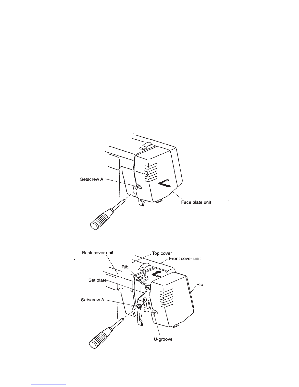
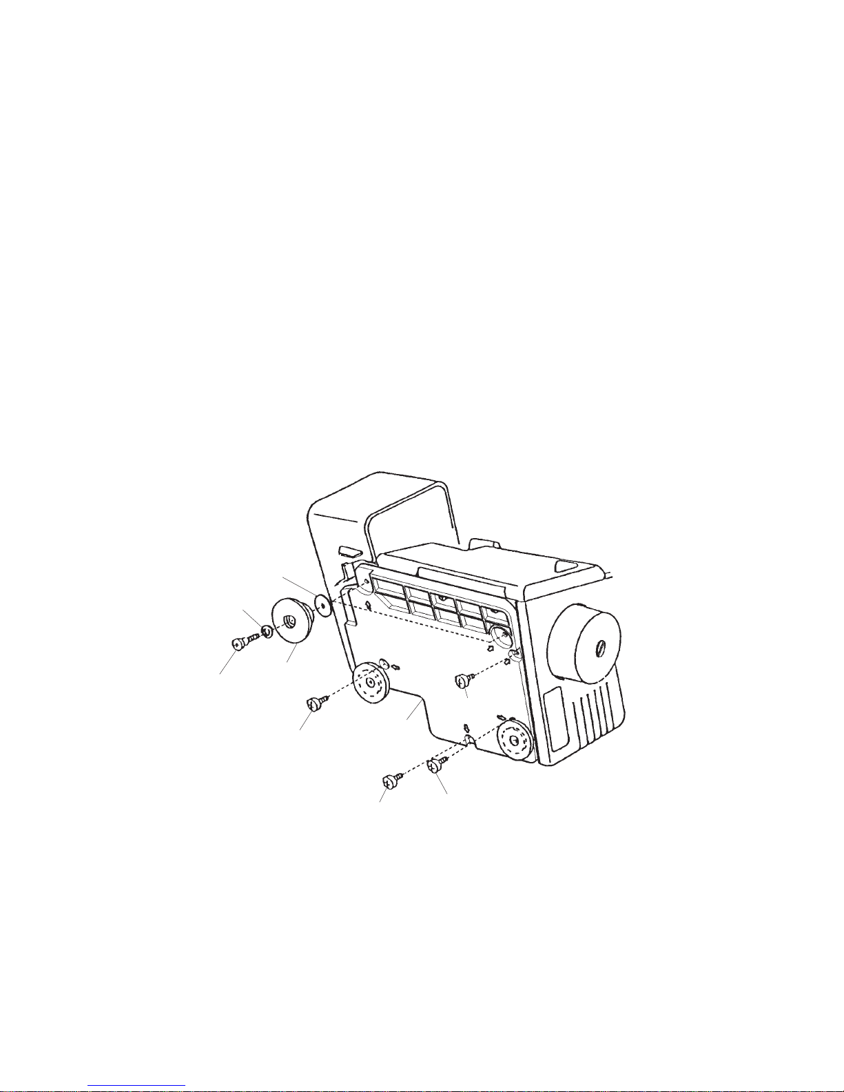
To remove:
1. Loosen the setscrew A and remove the face plate unit.
To attach:
2. Fit the U-groove of the face plate between the setscrew A and set plate, put the rib of the face
plate into the front cover unit and the back cover unit. Tighten the setscrew A.
TO CHANGE THE FACE PLATE UNIT

2
990D
Belt cover unit
Setscrew A
Setscrew B
Rib
Rib
To remove:
1. Loosen the setscrew A and remove the setscrew B.
2. Remove the belt cover unit.
To attach:
3. Put the ribs of belt cover into the front cover unit and tighten the setscrew A and B.
TO CHANGE THE BELT COVER UNIT
Front cover
3
990D
Top cover
Front cover unit
Setscrews A
Rib
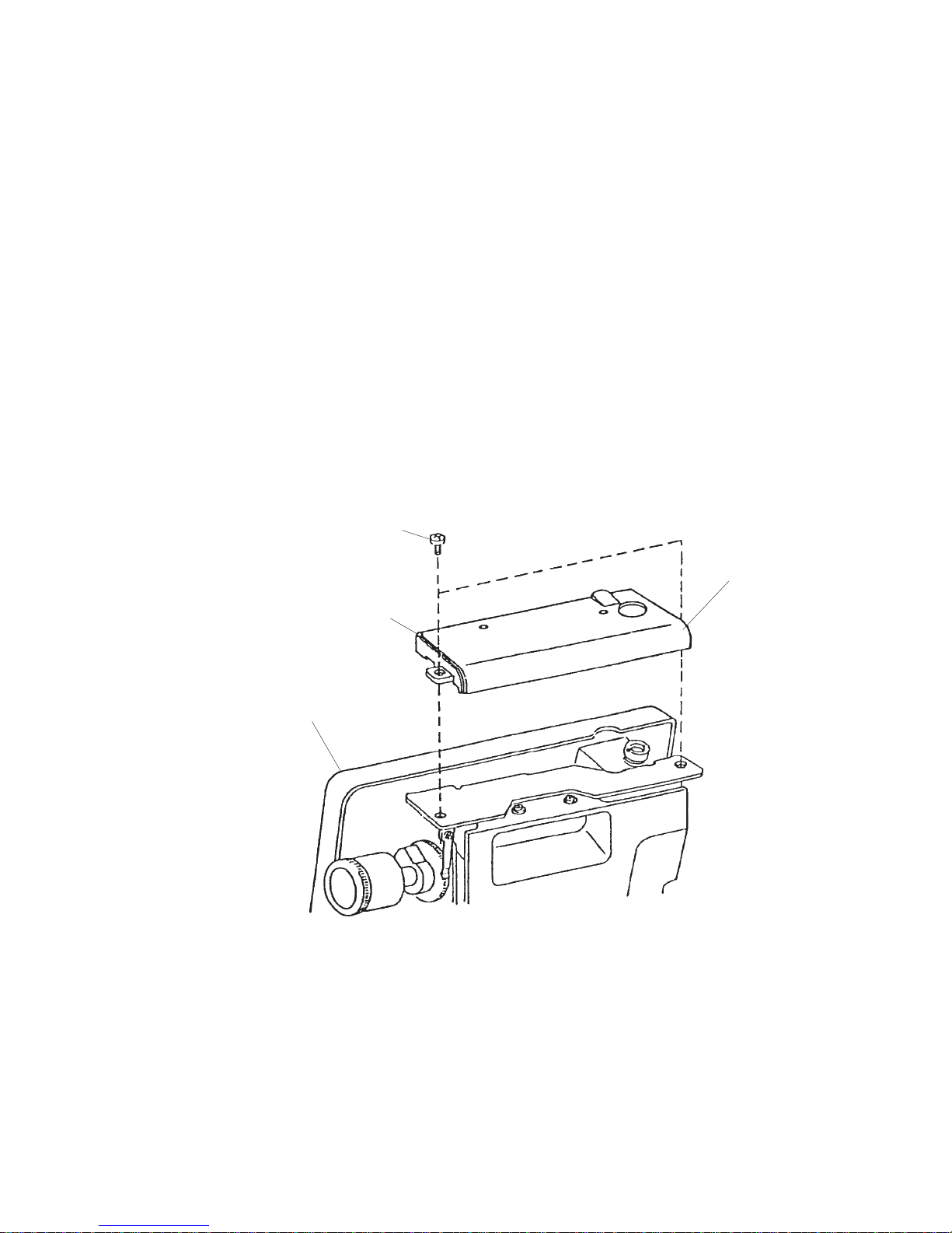
To remove:
1. Remove the face plate unit and belt cover unit.
2. Remove the two setscrews A. Remove the top cover.
To attach:
3. Put the ribs of top cover into the front cover unit. Tighten setscrews A.
TO CHANGE THE TOP COVER
4
990D
Setscrew B
Upper looper should be set
at its lowest position
Looper cover unit
Setscrew C
Setscrew D
Setscrews A
Front cover unit
Setscrew E
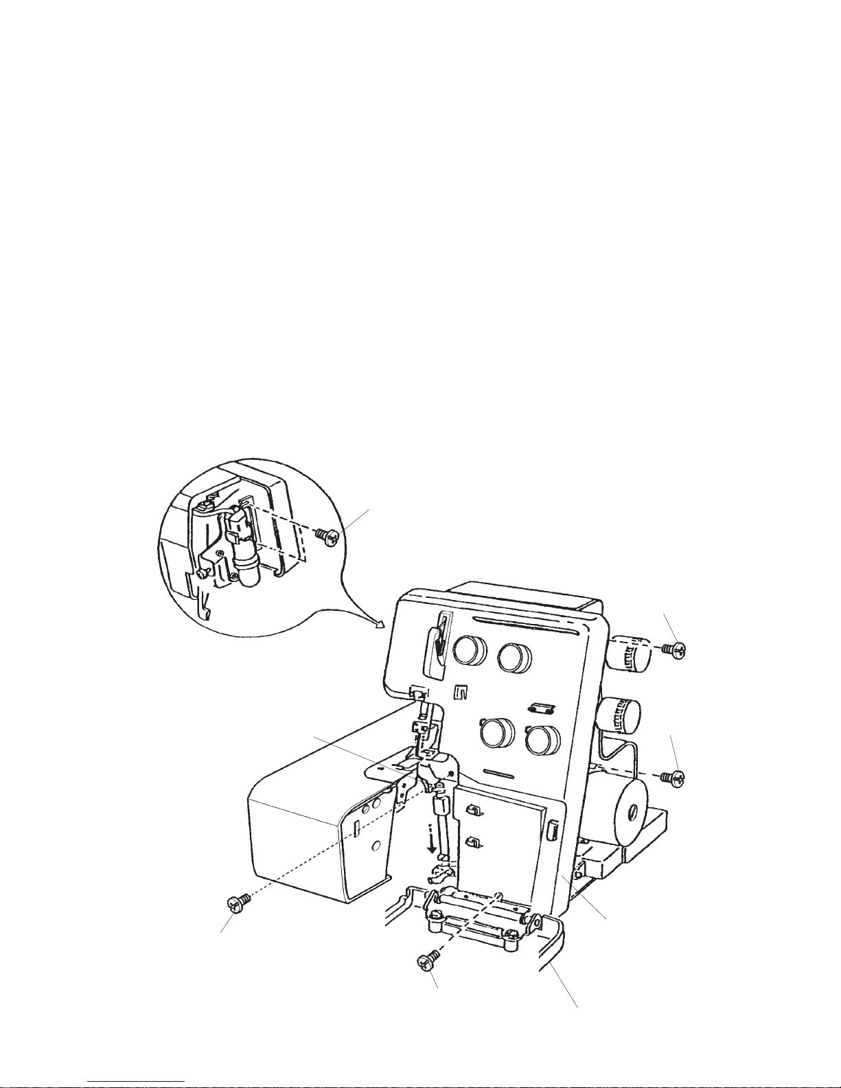
To remove:
1. Remove the face cover and belt cover unit.
2. Turn the handwheel toward you with your hand, and set the upper looper at its lowest position,
and remove the setscrews A, B, C, D, E and the front cover unit.
To attach:
3. Attach the front cov e r unit with setscrews A, B, C, D and E.
4. Attach the belt cover unit and face plate unit.
TO CHANGE THE FRONT COVER UNIT
5
990D
Side cover unit
Set plate
Setscrews A
U-grooves
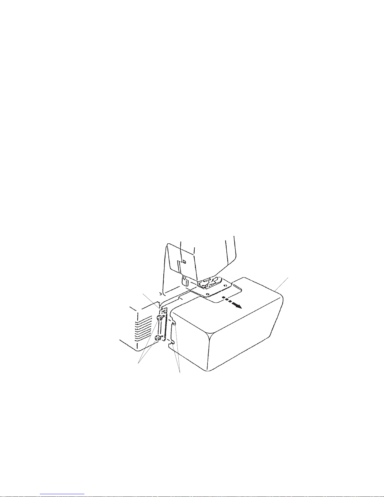
To remove:
1. Loosen the setscrew A and remove the side cover unit.
To attach:
2. Fit the U-grooves of the side cover between the setscrews A and the set plate.
3. Tighten the setscrews A.
TO CHANGE THE SIDE COVER UNIT
6
990D
Washer
Washer
Base
cushion F
Hinge screw E
Setscrew C
Setscrew B
Machine base
Setscrew A
Setscrew D
To remove:
1. Remove the setscrews A, B, C, D and two hinge screws E, and remove two base cushions F
and washers.
2. Remove the machine base.
NOTE: Do not remove another two base cushions.
To attach:
3. Attach the machine base unit, and tighten the setscrews A, B, C and D.
4. Attach the two base cushions F, washers, and tighten the hinge screws E.
TO CHANGE THE MACHINE BASE UNIT

7
990D
To remove:
1. Remove the belt cover unit.
2. Remove the setscrews A and pull out the cord connectors.
To attach:
3. Insert the cord connectors as shown below.
4. Attach the machine socket, and tighten two setscrews A and attach the belt cover unit.
TO CHANGE THE MACHINE SOCKET
Cord with ridge
Cord with ridge
8
990D
A
E
C
FB
D
787 - G05
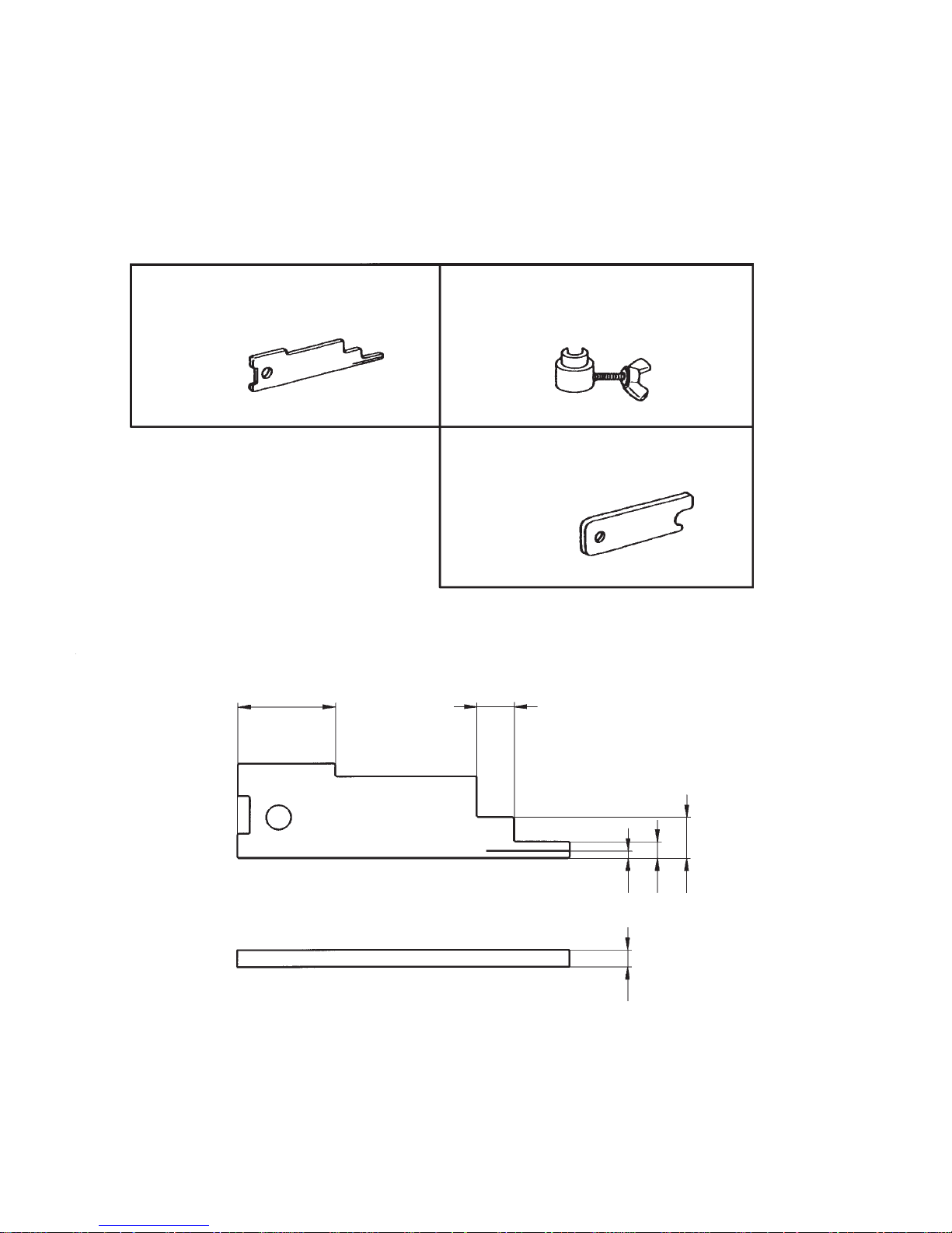
PREPARATION BEFORE THE ADJUSTMENT
Use the following gauges for the correct setting and adjustment.
Thickness gauge
No. 787-G05
Needle bar gauge
No. 787-G02
Thickness gauge
No. 787-G03
* Each part, indicated by an alphabet, of the thickness gauge No.787-G05 is used for the following
adjustments:
A: Adjustment of needle bar height
B: Adjustment of presser bar height
C: Adjustment of feed dog height
D: Adjustment of needle and upper looper timing
E: Adjustment of needle and upper looper timing
F: Adjustment of needle and feed dog timing
9
990D
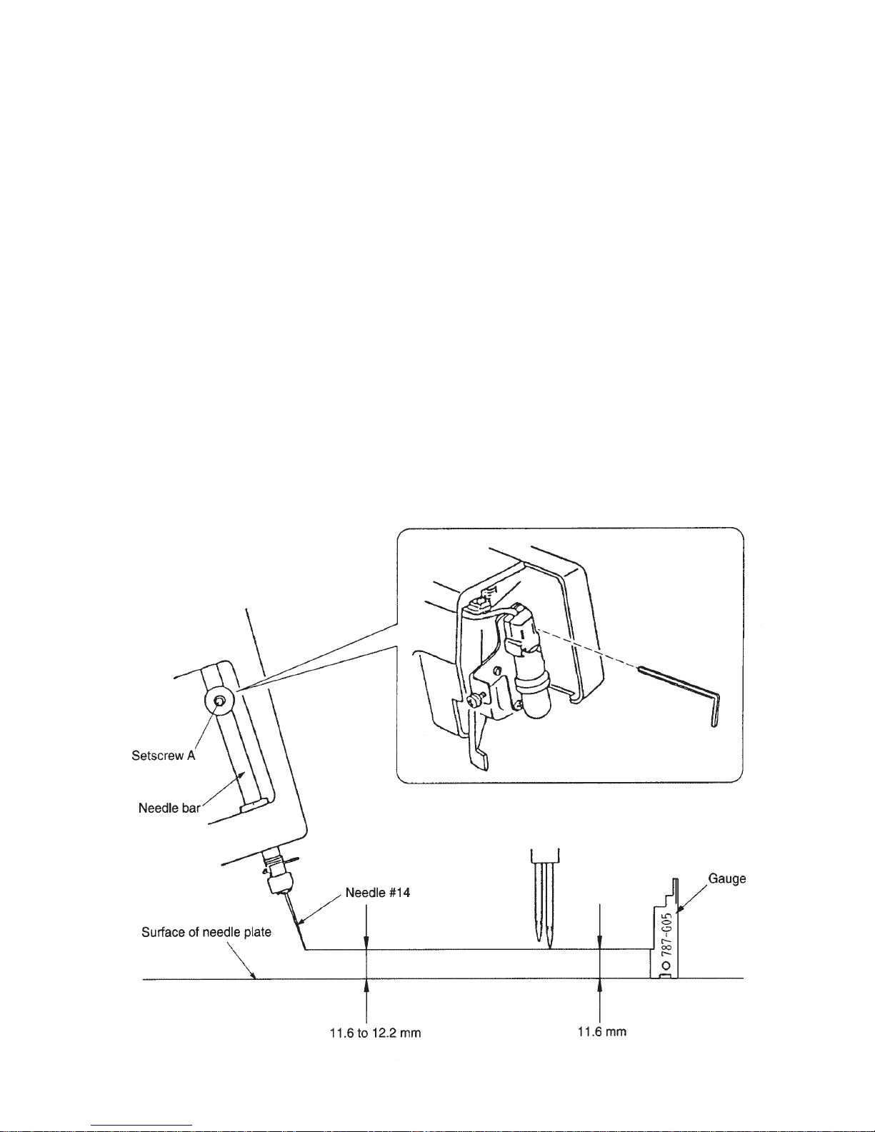
Correct Setting:
The distance between the tip of needle on the right and the surface of needle plate should be 11.6
to 12.2 mm when the needle bar is at the highest position.
To adjust:
1. Remove the face plate unit.
2. Turn the handwheel toward you with your hand, and set the needle bar at its highest position.
3. Loosen the setscrew A to adjust the height, and tighten the setscrew A after the adjustment is
done.
4. Turn the handwheel toward you one complete turn, and recheck the needle bar height.
5. Attach the face plate unit.
TO ADJUST THE NEEDLE HEIGHT
10
990D
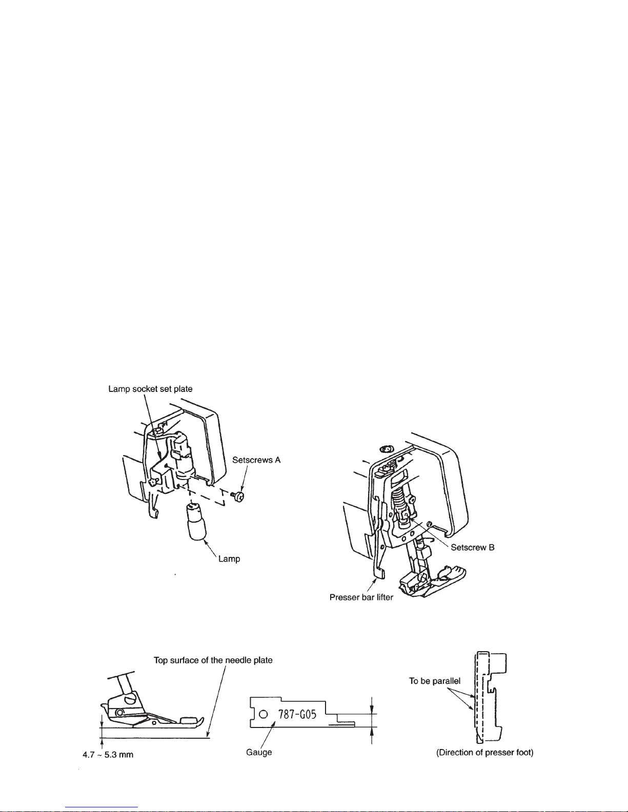
Correct Setting:
The distance between the surface of the needle plate and the bottom of presser foot should be 4.7
to 5.3 mm when the presser bar lifter is raised.
To adjust:
1. Remove the face plate unit. Remove the setscrews A and the lamp fixing plate.
2. Raise the presser bar lifter, and loosen the setscrews B.
Then adjust the presser bar height, the side of presser foot should be parallel with the hole of
needle plate.
3. Tighten the setscrew B.
4. Attach the lamp fixing plate with the setscrews A and attach the lamp.
5. Attach the face plate unit.
TO ADJUST THE PRESSER BAR HEIGHT
11
990D
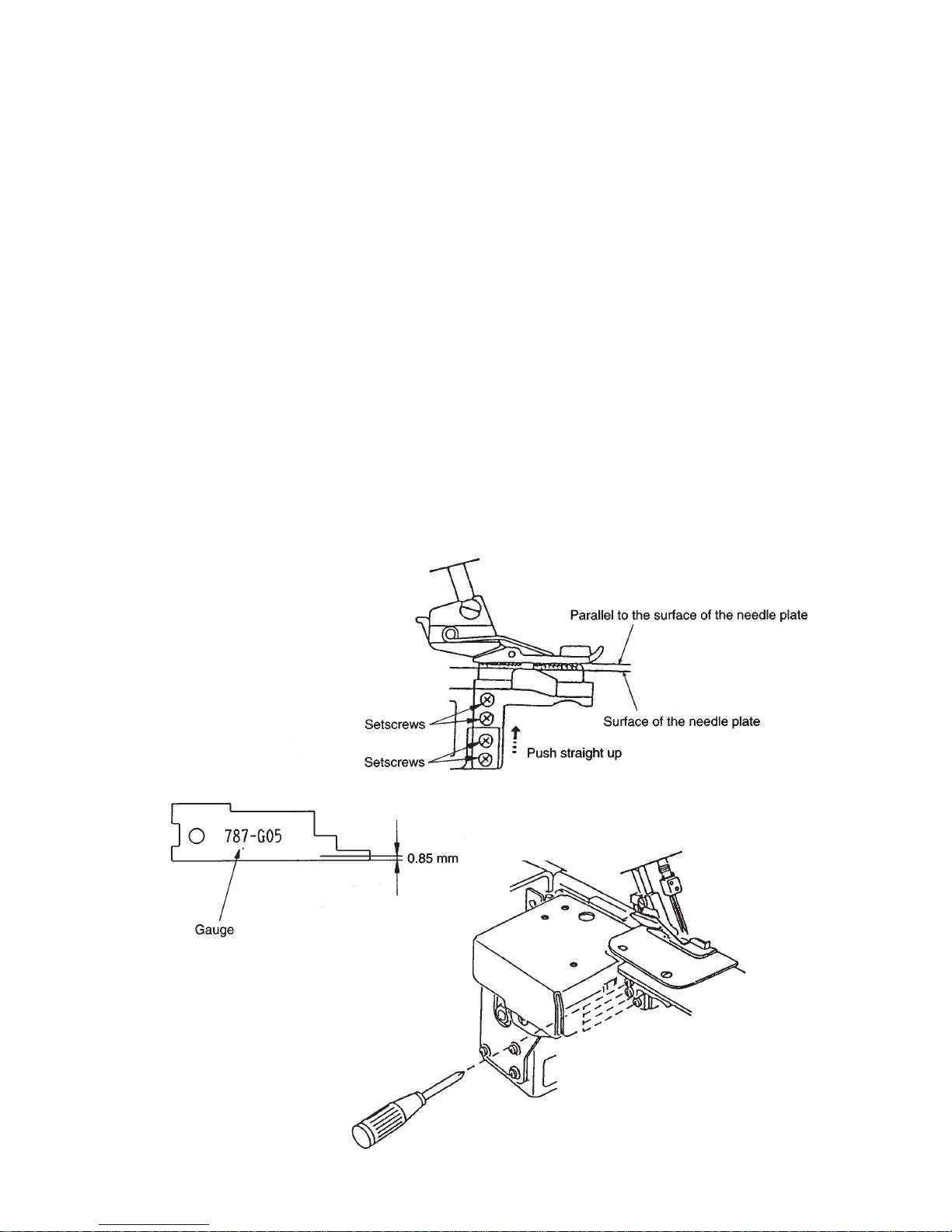
Correct Setting:
When the presser foot is lowered and feed dog is at its highest position, the distance between the
surface of needle plate and bottom of presser foot should be 0.75 to 0.95 mm.
To adjust:
1. Set the stitch length dial at “3” and the differential feed dial at “1.0”.
2. Lower the presser foot and raise the feed dog to its highest position by turning the handwheel.
3. Loosen the feed dog screws A (2 pcs.).
4. Push the feed dog straight upward and adjust the distance between the surface of needle plate
and bottom of presser foot, then tighten the setscrews A (2 pcs.).
5. Check the feed dog height by turning the handwheel toward you.
TO ADJUST THE FEED DOG HEIGHT
12
990D
TO ADJUST THE TIMING OF THE NEEDLE AND THE FEED DOG
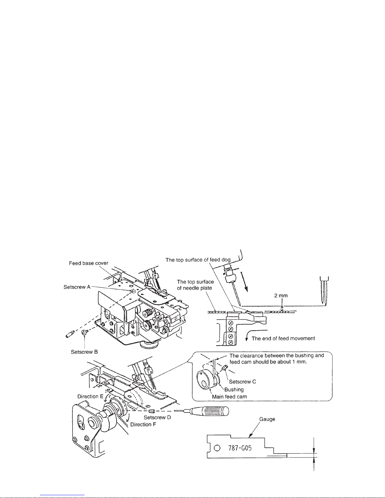
Correct Setting:
When the tip of right needle is at 2 ~ 4 mm above the needle plate in its downward motion,
and lowered presserr foot, the top of the feed dog teeth should be level to the top surface of needle
plate at their rearmost position.
Before adjustment, check if needle bar height and feed dog height are correct.
To adjust:
1. Loosen setscrew A and remove setscrew B, remove feed base cover.
2. Set the stitch length dial at “3” and differentiial feed dial at “1.0”.
3. Raise the presser foot and move the tip of right needle at 2 ~ 4 mm above the needle plate in its
downward motion by turning the handwheel.
4 Lower the presser foot, and loose two setscrews C for main feed cam, two setscrews D
for sub feed cam, annd adjust the position of the subb feed cam and tighten setscrews D.
* Turn the sub feed cam to the direction E if the feed dog is lower than the surface of the
needle plate.
* Turn the sub feed cam to the direction F if the feed dog is higher than the surface of the needle
plate.
5. Set the main feed cam to keep the clearance between the bushing and main feed cam to about
1 mm, and tighten two setscrewsss C.
Attach the feed base cover with setscrews A and B.
13
990D
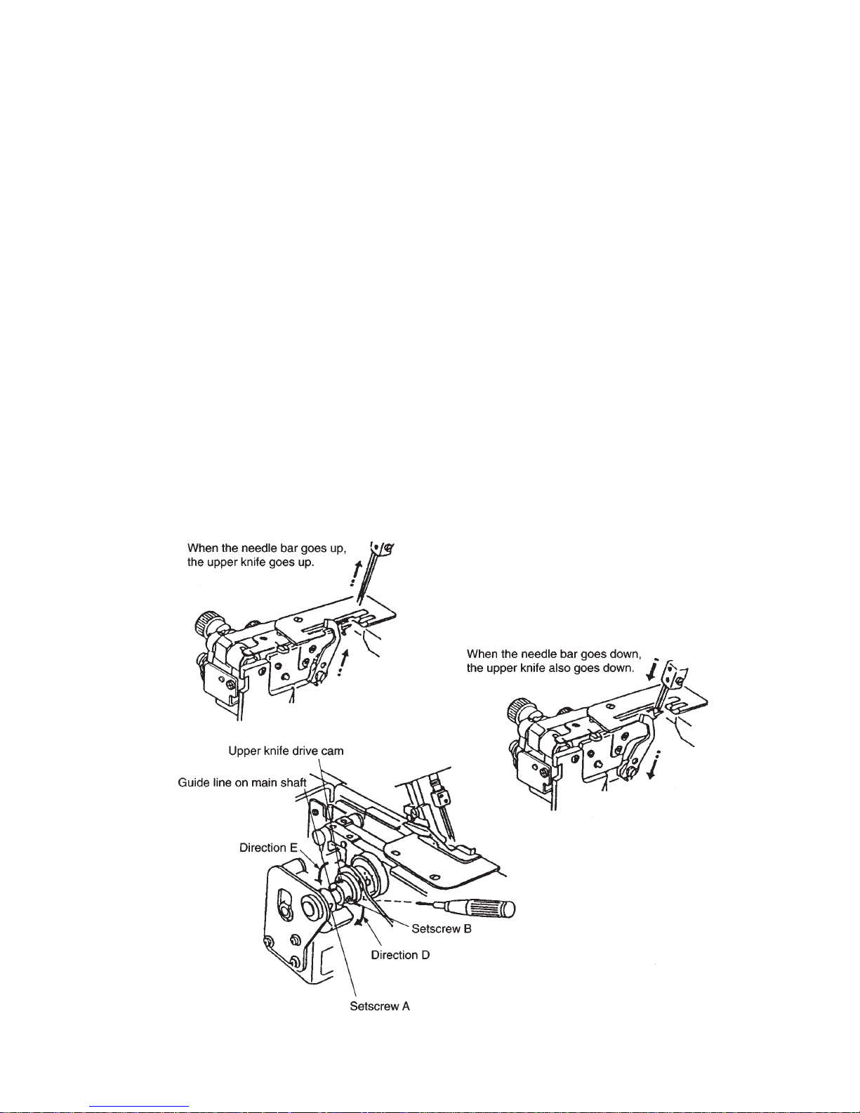
Correct Setting:
The upper knife timing is the same as that of the needle bar. In fact, when the needle bar is at
highest position, the upper knife should be also at its highest position.
To adjust:
1. Remove the feed base cover unit.
2. Loosen two setscrews A, and move the balance weight to left.
3. Loosen two setscrews B, and adjust the needle and upper knife timing is being delay.
# Turn the upper knife drive cam to the direction D when the upper knife timing is being delay.
# Turn the upper knife drive cam to the direciton E when the upper knife timing is too soon.
4. Tighten the two setscrews B firmly. Move the balance weight to right.
Match the guide line on the balance weight with the one of the main shaft correctly.
Thennn tighten the two screws A.
5. Turn the handwheel toward you one cycle, and recheck the needle and the upper knife timing.
6. Attach the feed base cover.
TO ADJUST THE TIMING OF THE NEEDLE AND THE UPPER KNIFE
 Loading...