


Robust Panel PC APC-9172
APC-9172
Intel® Core 2 Duo Processor
Industrial Panel PC
With 17” TFT LCD &
Two PCI expansion slots
APC-9172 Manual 2nd Ed.
Sept 2007

Robust Panel PC APC-9172
Copyright Notice
This document is copyrighted, 2007. All rights are reserved. The
original manufacturer reserves the right to make improvements to
the products described in this manual at any time without notice.
No part of this manual may be reproduced, copied, translated, or
transmitted in any form or by any means without the prior written
permission of the original manufacturer. Information provided in
this manual is intended to be accurate and reliable. However, the
original manufacturer assumes no responsibility for its use, or for
any infringements upon the rights of third parties that may result
from its use.
The material in this document is for product information only and is
subject to change without notice. While reasonable efforts have
been made in the preparation of this document to assure its
accuracy, AAEON assumes no liabilities resulting from errors or
omissions in this document, or from the use of the information
contained herein.
AAEON reserves the right to make changes in the product design
without notice to its users.
i

Robust Panel PC APC-9172
Acknowledgments
Intel
IBM, PC/AT, PS/2 are trademarks of International Business
Microsoft Windows
All other product names or trademarks are properties of their
respective owners.
®
and Pentium® are registered trademarks of Intel®
Corporation.
Machines Corporation.
®
is a registered trademark of Microsoft
Corporation.
ii

Robust Panel PC APC-9172
Packing List
Before you begin operating your PC, please make sure that the
following materials have been shipped:
1 APC-9172 Robust Panel PC
2 Easy stand
1 Waterproof sponge
12 Panelmount clips & screws
1 Screw bag
1 CD-ROM for manual (in PDF format) and drivers
If any of these items should be missing or damaged, please
contact your distributor or sales representative immediately.
iii

Robust Panel PC APC-9172
Safety & Warranty
1. Read these safety instructions carefully.
2. Keep this user's manual for later reference.
3. Disconnect this equipment from any AC outlet before cleaning. Do
not use liquid or spray detergents for cleaning. Use a damp cl oth.
4. For pluggable equipment, the power outlet must be installed near
the equipment and must be easily accessible.
5. Keep this equipment away from humidity.
6. Put this equipment on a firm surface during installation. Dropping
it or letting it fall could cause damage.
7. The openings on the enclosure are for air convection. Protect the
equipment from overheating. DO NOT COVER THE OPENINGS.
8. Make sure the voltage of the power source is correct before
connecting the equipment to the power outlet.
9. Position the power cord so that people cannot step on it. Do not
place anything over the power cord.
10. All cautions and warnings on the equipment should be noted.
11. If the equipment is not used for a long time, disconnect it from the
power source to avoid damage by transient over-voltage.
12. Never pour any liquid into an opening. This could cause fire or
electrical shock.
13. Never open the equipment. For safety reasons, only qualified
service personnel should open the equipment.
14. If any of the following situations arises, get the equipment
checked by service personnel:
a. The power cord or plug is damaged.
b. Liquid has penetrated into the equipment.
c. The equipment has been exposed to moisture.
iv

Robust Panel PC APC-9172
d. The equipment does not work well, or you cannot get it
to work according to the user’s manual.
e. The equipment has been dropped and damaged.
f. The equipment has obvious signs of breakage.
15. DO NOT LEAVE THIS EQUIPMENT IN AN ENVIRONMENT
WHERE THE STORAGE TEMPERATURE IS BELOW -20°C
(-4°F) OR ABOVE 60°C (140°F). IT MAY DAMAGE THE
EQUIPMENT.
16. External equipment intended for connection to signal input/output
or other connectors, shall comply with relevant UL / IEC standard
(e.g. UL 60950 for IT equip m ent and UL 2601-1 / IEC 60601
series for medical electrical equipment). In addition, all such
combinations – systems – shall comply with the standard IEC
60601-1-1, Safety requirements for medical electrical systems.
Equipment not complying with UL 2601-1 shall be kept outsid e the
patient environment, as defined in the standard.
FCC Safety
This device complies with Part 15 FCC Rules.
Operation is subject to the following two
conditions: (1) this device may not cause
harmful interference, and (2) this device must
accept any interference received including
interference that may cause undesired
operation.
v

Robust Panel PC APC-9172
Below Table for China RoHS Requirements
产品中有毒有害物质或元素名称及含量
AAEON Panel PC/ Workstation
有毒有害物质或元素
部件名称
印刷电路板
及其电子组件
外部信号
连接器及线材
外壳 × ○ ○ ○ ○ ○
中央处理器
与内存
硬盘 × ○ ○ ○ ○ ○
液晶模块 × ○ ○ ○ ○ ○
光驱 × ○ ○ ○ ○ ○
触控模块 × ○ ○ ○ ○ ○
电源 × ○ ○ ○ ○ ○
O:表示该有毒有害物质在该部件所有均质材料中的含量均在
SJ/T 11363-2006 标准规定的限量要求以下。
X:表示该有毒有害物质至少在该部件的某一均质材料中的含量超出
SJ/T 11363-2006 标准规定的限量要求。
备注:
一、此产品所标示之环保使用期限,系指在一般正常使用状况下。
二、上述部件物质中央处理器、内存、硬盘、光驱、触控模块为选购品。
铅
(Pb)汞 (Hg)镉 (Cd)
× ○ ○ ○ ○ ○
× ○ ○ ○ ○ ○
× ○ ○ ○ ○ ○
六价铬
(Cr(VI))
多溴联苯
(PBB)
多溴二苯醚
(PBDE)
vi

Robust Panel PC APC-9172
Contents
Chapter 1 General Information
1.1 Introduction................................................................ 1-2
1.2 Features.................................................................... 1-3
1.3 Specifications............................................................ 1-4
1.4 Dimension ................................................................. 1-7
Chapter 2 Hardware Installation
2.1 Safety Precautions.................................................... 2-2
2.2 COM1-4 RS-232/422/485 Serial Port Connector (CN16)
.....................................................................................2-3
2.3 HDD Installation ........................................................2-4
2.4 CD-ROM Installation .................................................2-6
2.5 Easy Stand Installation.............................................. 2-7
2.6 Panel Mount Kit Installation....................................... 2-8
2.7 Waterproof sponge Installation ................................. 2-9
Chapter 3 BIOS Installation
3.1 System Test and Initialization. ..................................3-2
3.2 Award BIOS Setup.................................................... 3-3
Chapter 4 Driver Installation
4.1 Installation.................................................................4-3
4.2 Limitations.................................................................4-4
vii

Robust Panel PC APC-9172
Appendix A I/O Information
A.1 I/O Address Map....................................................A-2
A.2 Memory Address Map............................................A-3
A.3 IRQ Mapping Chart................................................A-4
A.4 DMA Channel Assignments...................................A-4
viii

Robust Panel PC APC-9172
Chapter
1
General
Information
Chapter 1 General Information 1- 1

Robust Panel PC APC-9172
1.1 Introduction
APC-9172 is first Core 2 Duo industrial board in AAEON Panel PC
product line. It features a PGA478 socket that can accommodate
Core 2 Duo Processor, supporting FSB up to 400/533/667MHz.
Best performance for multimedia solution
AAEON's APC-9172 also supports DDR DRAM up to 2GB. It can
provide the strong multimedia functions. Therefore APC-9172 can
be broadly implemented in several markets, such as Point of sale,
point of information (Kiosk), and gaming markets.
Multi-Function Core 2 Duo Platform
If you are looking for powerful multi-media applications,
APC-9172 is the one. APC-9172 integrates 17” color TFT LCD,
Audio and Ethernet function; meanwhile it also supports 5 USB2.0,
mini PCI, and two PCI slots. With flexible expansion, you get easy
access to solutions ranging from Modem, Storage, Sound Card,
SCSI card, Audio/Video capture card, Wireless LAN module, to
Bluetooth module. Especially for customers whom application is
various or changing, APC-9172 reserves more than enough
flexibility for future expansion.
APC-9172 provides more CPU options for different applications.
You can choose Core 2 Duo processor up to 2.0G for high
performance application.
Chapter 1 General Information 1-2

Robust Panel PC APC-9172
1.2 Features
17” TFT SXGA (1280 x 1024) LCD
All-in-one SBC supports Socket 478 based Intel
®
Core 2 Duo
Processor
Anti-vibration disk drive bay for HDD
Water-proof and anti-scratch IP-65 certified aluminum front
panel with USB port certification
Two free PCI expansion slots
Resistive TouchScreen (optional)
Chapter 1 General Information 1- 3

Robust Panel PC APC-9172
1.3 Specifications
System
Construction Heavy-duty steel chassis & IP-65
certified aluminum front panel (or
optional stainless steel front panel)
CPU Socket 478 based Intel
®
Core 2 Duo
Processor up to 2.0G with FSB
400/533/667MHz
LCD/CRT Intel
System Memory DDRII SODIMM Socket x 1 up to 2G
OS Support Windows
Storage Disk Drive Anti-vibration 2.5”HDD, Slim
®
945GM, AGP 4X Controller
®
2000, Windows® XP,
Windows
®
XP Embedded (Optional)
FDD and Slim CD-ROM
I/O Chipset 2 Serial ports: 2 x RS-232, 1 x
RS-232/422/485 (COM 4 is reserved for
touch screen);
1 parallel port (supports ECP/EPP);
1 PS/2 mouse and keyboard port;
1 VGA port Mic-in, Line-in, Line-out
Ethernet Intel
®
85573L, 10/100/1000Base-TX, 2 x
Gigabit LAN ports
Expansion slots 2 PCI slots, 1 Mini PCI socket, 6-in-1
card reader, supports CompactFlash
Chapter 1 General Information 1-4
®

Robust Panel PC APC-9172
(Type I/II), Secure Digital, Multi Media
Card, Memory Stick (PRO) and Smart
Media
USB ports 4 USB 2.0 ports on rear panel;
1 USB 2.0 port on front panel (Lockable
by BIOS) Because of USB chipset
limitation, front USB port and Card
reader USB interface are linked
together, when user “disable” front USB
port (USB Port 3 controller), the card
reader must be forced to disable at the
same time
Power Supply Universal 250W switching power supply
Mechanical and Environment
Front Panel PMS 2965C (Dark Blue)
Mounting Panelmount, VESA 75/100mm holes
Dimension 19” x 15.7” x 5.7”
(483mm x 399mm x 145mm)
Carton Dimension 24.4” x 20.6” x 13.8”
(620mm x 522mm x 351mm)
Gross Weight 15 Kg (33 lb)
Operating
32°F~122°F (0°C ~50°C)
temperature
Storage temperature
-4°F~140°F (-20°C~60°C)
Chapter 1 General Information 1- 5

Robust Panel PC APC-9172
Operating humidity
Vibration 1.5G / 5~500Hz (Random/ operation)
Shock 15G peak acceleration (11 msec.
10 to 90% @35°C, non-condensin
duration)/ operation
EMC CE/FCC Class A
Power Supply
AC input 250W:
Output rating: 250W
Input voltage: 100VAC~240VAC@47~63Hz
Output voltage:
+3.3V@16A, +5V@25A, +12V@13A,
+5VSB@2A, -5V@0.3A, -12V@0.8A
LCD Specifications
Display type 17” color TFT LCD
Max. Resolution 1280 x 102 4
Max. Colors 16.2M
Dot size (mm) 0.264 x 0.264
Luminance (cd/m
Viewing angle
2
) 260 (TYP)
140°(H)
130°(V)
Back Light MTB
50,000 (hrs)
Chapter 1 General Information 1-6
Robust Panel PC APC-9172
TouchScreen (Optional)
Type 8-wire, analog resistive
Resolution 2048 x 2048
Light transmission >80%
Lifetime 10 million activations
OS support Windows 2000, Windows XP, Windows
XP Embedded
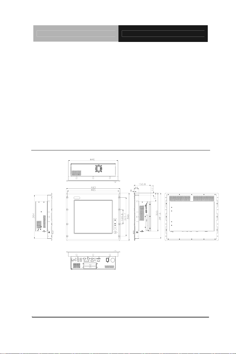
1.4 Dimension
Unit : mm
APC-9172
Cutout Size : 449 X 367
Chapter 1 General Information 1- 7

Robust Panel PC APC-9172
Chapter
2
Hardware
Installation
Chapter 2 Hardware Installation 2-1
Robust Panel PC APC-9172
2.1 Safety Precautions
Always completely disconnect the power cord
from your board whenever you are working on
it. Do not make connections while the power is
on, because a sudden rush of power can
damage sensitive electronic components.
Always ground yourself to remove any static
charge before touching the board. Modern
electronic devices are very sensitive to static
electric charges. Use a grounding wrist strap at
all times. Place all electronic components on a
static-dissipative surface or in a static-shielded
bag when they are not in the chassis
Chapter 2 Hardware Installation 2 - 2

Robust Panel PC APC-9172
2.2 COM1~4 RS-232/422/485 Serial Port Connector (CN16)
5
9
1
6
COM 4 is reserved for touch screen.
Pin Signal Pin Signal
1 DCD1 2 DSR1
3 RXD1 4 RTS1
5 TXD1 6 CTS1
7 DTR1 8 RI1
9 GND
Chapter 2 Hardware Installation
2 - 3

Robust Panel PC APC-9172
2.3 HDD Installation
Step 1: Screw up the HDD onto HDD Brack et
Step 2: Fasten the 4 pieces of anti- vibration Rubbers on the HDD
bracket.
Step 3: Screw two brackets with four screws to fasten Anti-vibration
Rubbers.
Chapter 2 Hardware Installation 2 - 4

Robust Panel PC APC-9172
Step 4: Put the rubbers into indentations to fix the whole HDD brackets
with HDD on HDD box
Step 5: Fix HDD box on the units with three screws
Step 6: Plug into HDD cable and you’ve done HDD installation
Chapter 2 Hardware Installation
2 - 5

Robust Panel PC APC-9172
2.4 CD-ROM Installation
Step 1: Fasten the CD-ROM on brackets
Step 2: Fasten the transferring bar with a pair screws on the back of
CD-ROM
Step 3: Fasten the CD-ROM module on the on the chassis and plug the
cable
Chapter 2 Hardware Installation 2 - 6

Robust Panel PC APC-9172
2.5 Easy Stand Installation
There’re two L-shaped easy stands come with the product. Refer to
the following illustration to install it.
1. Fix the L-shaped easy stands with the screws on both
sides of the monitor. See the illustration below:
*4-M4 Screw
Chapter 2 Hardware Installation
2 - 7

Robust Panel PC APC-9172
2.6 Panelmount Kit Installation
Some screw sets will come with the product for user to mount the
monitor on the wall. See the steps below along with the illustration.
Step 1: Bore the screw into the screw nut.
Step 2: Locate the screw set into the hole around the monitor as the right
illustration and pull it back to lock the screw set on the hole.
Step 3: Turn the screw around to make it tight until it is closed to the wall.
Step 4: Lock the monitor to the wall with the screw set which mean
you’ve done a good job.
1
2
3
4
Panel Mounting
Chapter 2 Hardware Installation 2 - 8

Robust Panel PC APC-9172
2.7 Waterproof Sponge Installation
The following illustration shows you how to lodge the waterproof
sponge in the back of the monitor set.
1. Lodge the Sponge in the back of the monitor set.
2. Locate the monitor set on the wall.
Sponge
Wall
Chapter 2 Hardware Installation
2 - 9

Robust Panel PC APC-9172
Chapter
3
BIOS
Installation
Chapter 3 BIOS Installation 3-1

Robust Panel PC APC-9172
3.1 System test and initialization
These routines test and initialize board hardware. If the routines
encounter an error during the tests, you will either hear a few short
beeps or see an error message on the screen. There are two kinds
of errors: fatal and non-fatal. The system can usually continue the
boot up sequence with non-fatal errors. Non-fatal error messages
usually appear on the screen along with the following instructions:
Press <F1> to RESUME
Write down the message and press the F1 key to continue the boot
up sequence.
System configuration verification
These routines check the current system configuration against the
values stored in the CMOS memory. If they do not match, the
program outputs an error message. You will then need to run the
BIOS setup program to set the configuration information in memory.
There are three situations in which you will need to change the
CMOS settings:
1. You are starting your system for the first time
You have changed the hardware attached to your system
The CMOS memory has lost power and the configuration
information has been erased.
The APC-9172 CMOS memory has an integral lithium battery
backup for data retention. However, you will need to replace
the complete unit when it finally runs down.
Chapter 3 BIOS Installation 3-2

Robust Panel PC APC-9172
3.2 Award BIOS Setup
Awards BIOS ROM has a built-in Setup program that allows users
to modify the basic system configuration. This type of information is
stored in battery-backed CMOS RAM so that it retains the Setup
information when the power is turned off.
Entering Setup
Power on the computer and press <Del> immediately. This will
allow you to enter Setup.
Standard CMOS Features
Use this menu for basic system configuration. (Date, t ime, IDE,
etc.)
Advanced BIOS Features
Use this menu to set the advanced features available on your
system.
Advanced Chipset Features
Use this menu to change the values in the chipset registers and
optimize your system performance.
Integrated Peripherals
Use this menu to specify your settings for integrated peripherals.
(Primary slave, secondary slave, keyboard, mouse etc.)
Power Management Setup
Use this menu to specify your settings for power management.
(HDD power down, power on by ring, KB wake up, etc.)
PnP/PCI Configurations
This entry appears if your system supports PnP/PCI.
PC Health Status
This menu allows you to set the shutdown temperature for your
Chapter 3 BIOS Installation 3-3

Robust Panel PC APC-9172
system.
Frequency/Voltage Control
Use this menu to specify your settings for auto detect DIMM/PCI
clock and spread spectrum.
Load Fail-Safe Defaults
Use this menu to load the BIOS default values for the
minimal/stable performance for your system to operate.
Load Optimized Defaults
Use this menu to load the BIOS default values that are factory
settings for optimal performance system operations. While AWARD
has designated the custom BIOS to maximize performance, the
factory has the right to change these defaults to meet their needs.
Set Supervisor/User Password
Use this menu to set Supervisor/User Passwords.
Save and Exit Setup
Save CMOS value changes to CMOS and exit setup.
Exit Without Saving
Abandon all CMOS value changes and exit setup.
You can refer to the "AAEON BIOS Item Description.pdf" file in
the CD for the meaning of each setting in this chapter.
Limitation:
1. Due to Intel chipset limitation, when CMOS was set up to
“LCD + CRT”, the LCD display will not support full-screen
appearance.
2. Because of USB chipset limitation, front USB port and Card
reader USB interface are linked together, when user
“disable” front USB port (USB Port 3 controller), the card
reader must be forced to disable at same time.
Chapter 3 BIOS Installation 3-4

Robust Panel PC APC-9172
Chapter
4
Driv
Installation
Chapter 4 Driver Installation 4 - 1
er

Robust Panel PC APC-9172
There are several installation ways depending on the driver
package under different Operating System application. The
Autorun program will run automatically. However, if the
Autorun program cannot be run smoothly, please follow the
sequence below to install the drivers:
Step 1– INF Driver Installation
Step 2– VGA Driver Installation
Step 3– Intel LAN Driv er Installation
Step 4– Audio Driver Installation
Step 5– Card Reade r Driver Installation
Step 6– Touch Screen Drive r Insta llation
USB 2.0 Drivers are available for download using Windows
Update for both Windows XP and Windows 2000. For
additional information regarding USB 2.0 support in Windows
XP and Windows 2000, please visit
www.microsoft.com/hwdev/usb/.
For installation procedures of each driver, you may see the
details in the following.
Chapter 4 Driver Installation 4 - 2

Robust Panel PC APC-9172
4.1 Installation
Insert the APC-9172 CD-ROM into the CD-ROM drive and install
the drivers from Step 1 to Step 6 in order.
Step 1 – Install INF Driver
1. Click on the Step 1-INF folder
2. Double click on infinst_autol.exe
3. Follow the instructions that the window shows
4. The system will help you install the driver automatically
Step 2 – Install VGA Driver
1. Click on the Step 2 –VGA folder
2. Double click on win2k_xp1425.exe
3. Follow the instructions that the window shows
4. The system will help you install the driver automatically
Step 3 – Install Intel LAN Driver
1. Click on the Step 3 –Intel_LAN folder
2. Double click on PRO2KXP.exe
3. Follow the instructions that the window shows
4. The system will help you install the driver automatically
Step 4 – Install Audio Driver
1. Click on the Step 4 –AUDIO folder
Chapter 4 Drivers Installat ion 4 - 3

Robust Panel PC APC-9172
2. Double click on WDM_A395.exe
3. Follow the instructions that the window shows
4. The system will help you install the driver automatically
Step 5 – Install Card Reader Driver
1. Click on the Step 5 –Card_Reader folder
2. Double click on Setup.exe
3. Follow the instructions that the window shows
4. The system will help you install the driver automatically
Step 6 – Install Touch Screen Driver
1. Click on the Step 6 –TOUCH folder
2. Double click on Setup.exe
3. Follow the instructions that the window shows
4. The system will help you install the driver automatically
4.2 Limitations
1. The limitations you may need to notice when you start to
install the driver . For the sake of USB4 and USB5 community
of linkage, the card reader must be forced to disable when the
users “disable” front USB port.
2. If the length of the LAN cable connected to LAN 2 is over 35
meters, it may result in more than 10 times of time-out errors
during network transmission. We strongly recommend you
to use LAN 1 for this application.
Chapter 4 Driver Installation 4 - 4

Robust Panel PC APC-9172
A
Appendix
I/O Information
Appendix A I/O Information A-1

Robust Panel PC APC-9172
A.1 I/O Address Map
Appendix A I/O Information A-2

Robust Panel PC APC-9172
A.2 Memory Address Map
Appendix A I/O Information A-3

Robust Panel PC APC-9172
A.3 IRQ Mapping Chart
A.4 DMA Channel Assignments
Appendix A I/O Information A-4
 Loading...