


IXYS MCD72-16IO8B, MCD72-08IO8B, MCD72-12IO8B, MCD72-14IO8B, MCC72-12IO8B Datasheet
...
MCC 72 MCD 72
Thyristor Modules
Thyristor/Diode Modules
ITRMS = 2x 180 A
ITAVM = 2x 115 A
VRRM = 800-1800 V
VRSM |
VRRM |
|
Type |
|
|
|
VDSM |
VDRM |
|
|
|
|
|
V |
V |
|
Version 1 B |
|
Version 8 B |
|
|
|
|
||||
|
|
|
|
|
|
|
900 |
800 |
|
MCC 72-08io1 B |
-- |
MCC 72-08io8 B |
MCD 72-08io8 B |
1300 |
1200 |
|
MCC 72-12io1 B |
MCD 72-12io1B |
MCC 72-12io8 B |
MCD 72-12io8 B |
1500 |
1400 |
|
MCC 72-14io1 B |
-- |
MCC 72-14io8 B |
MCD 72-14io8 B |
1700 |
1600 |
|
MCC 72-16io1 B |
MCD 72-16io1B |
MCC 72-16io8 B |
MCD 72-16io8 B |
1900 |
1800 |
|
MCC 72-18io1 B |
-- |
MCC 72-18io8 B |
MCD 72-18io8 B |
|
|
|
|
|
|
|
Symbol |
Test Conditions |
|
|
Maximum Ratings |
||||
|
|
|
|
|
|
|||
ITRMS, IFRMS |
TVJ = TVJM |
|
|
180 |
A |
|||
ITAVM, IFAVM |
TC = 63°C; 180° sine |
115 |
A |
|||||
|
TC = 85°C; 180° sine |
85 |
A |
|||||
ITSM, IFSM |
TVJ = 45°C; |
|
t = 10 ms (50 Hz), sine |
1700 |
A |
|||
|
VR = 0 |
|
|
t = 8.3 ms (60 Hz), sine |
1800 |
A |
||
|
TVJ = TVJM |
|
t = 10 ms (50 Hz), sine |
1540 |
A |
|||
|
VR = 0 |
|
|
t = 8.3 ms (60 Hz), sine |
1640 |
A |
||
òi2dt |
T |
VJ |
= 45°C |
|
t = 10 ms (50 Hz), sine |
14 450 |
A2s |
|
|
VR = 0 |
|
|
t = 8.3 ms (60 Hz), sine |
13 500 |
A2s |
||
|
T |
VJ |
= T |
VJM |
|
t = 10 ms (50 Hz), sine |
11 850 |
A2s |
|
VR = 0 |
|
|
t = 8.3 ms (60 Hz), sine |
11 300 |
A2s |
||
|
|
|
|
|
|
|||
(di/dt)cr |
TVJ = TVJM |
|
repetitive, IT = 250 A |
150 |
A/ms |
|||
|
f |
=50 Hz, tP =200 ms |
|
|
||||
|
VD = 2/3 VDRM |
|
|
|
|
|||
|
|
|
|
A/ms |
||||
|
IG = 0.45 A |
|
non repetitive, IT = ITAVM |
500 |
||||
|
diG/dt = 0.45 A/ms |
|
|
|
|
|||
(dv/dt)cr |
TVJ = TVJM; |
|
VDR = 2/3 VDRM |
1000 |
V/ms |
|||
|
RGK = ¥; method 1 (linear voltage rise) |
|
|
|||||
PGM |
TVJ = TVJM |
|
tP = 30 ms |
10 |
W |
|||
|
IT = ITAVM |
|
tP = 300 ms |
5 |
W |
|||
PGAV |
|
|
|
|
|
|
0.5 |
W |
VRGM |
|
|
|
|
|
|
10 |
V |
TVJ |
|
|
|
|
|
|
-40...+125 |
°C |
TVJM |
|
|
|
|
|
|
125 |
°C |
Tstg |
|
|
|
|
|
|
-40...+125 |
°C |
VISOL |
50/60 Hz, RMS |
|
t = 1 min |
3000 |
V~ |
|||
|
IISOL £ 1 mA |
|
t = 1 s |
3600 |
V~ |
|||
Md |
Mounting torque |
(M5) |
2.5-4.0/22-35 Nm/lb.in. |
|||||
|
Terminal connection torque (M5) |
2.5-4.0/22-35 Nm/lb.in. |
||||||
Weight |
Typical including screws |
90 |
g |
|||||
|
|
|
|
|
|
|
|
|
Data according to IEC 60747 and refer to a single thyristor/diode unless otherwise stated. IXYS reserves the right to change limits, test conditions and dimensions
TO-240 AA |
6 7 |
3 |
|
2 |
4 |
1 |
5 |
|
3 |
6 7 |
1 |
5 4 2 |
MCC
Version 1 B
3 |
1 |
5 |
4 2 |
MCD |
|
|
|
Version 1 B |
|
|
|
3 |
6 |
1 |
5 |
2 |
MCC
Version 8 B
|
|
|
|
|
|
|
|
|
|
|
|
|
|
|
|
|
|
|
|
|
|
3 |
|
|
|
|
|
|
|
|
1 |
|
|
|
5 |
|
2 |
||||||
MCD
Version 8 B
Features
●International standard package, JEDEC TO-240 AA
●Direct copper bonded Al2O3 -ceramic base plate
●Planar passivated chips
●Isolation voltage 3600 V~
●UL registered, E 72873
●Gate-cathode twin pins for version 1B
Applications
●DC motor control
●Softstart AC motor controller
●Light, heat and temperature control
Advantages |
|
|
● |
Space and weight savings |
|
● |
Simple mounting with two screws |
|
● |
Improved temperature and power |
|
|
cycling |
|
● |
Reduced protection circuits |
032 |
|
|
|
© 2000 IXYS All rights reserved |
1 - 4 |
MCC 72
MCD 72
Symbol |
Test Conditions |
|
|
Characteristic Values |
||
IRRM, IDRM |
TVJ = TVJM; VR = VRRM; VD = VDRM |
|
5 |
mA |
||
VT, VF |
IT, IF = 300 A; TVJ = 25°C |
|
|
1.74 |
V |
|
|
|
|
|
|||
VT0 |
For power-loss calculations only (TVJ = 125°C) |
0.85 |
V |
|||
rT |
|
|
|
|
3.2 |
mW |
|
|
|
|
|
|
|
VGT |
VD = 6 V; |
TVJ = 25°C |
|
|
2.5 |
V |
|
|
TVJ = -40°C |
|
2.6 |
V |
|
IGT |
VD = 6 V; |
TVJ = 25°C |
|
|
150 |
mA |
|
|
TVJ = -40°C |
|
200 |
mA |
|
VGD |
TVJ = TVJM; |
VD = 2/3 VDRM |
|
0.2 |
V |
|
IGD |
|
|
|
|
10 |
mA |
IL |
TVJ = 25°C; tP = 10 ms; VD = 6 V |
|
450 |
mA |
||
|
IG = 0.45 A; diG/dt = 0.45 A/ms |
|
|
|
||
IH |
TVJ = 25°C; VD = 6 V; RGK = ¥ |
|
200 |
mA |
||
tgd |
TVJ = 25°C; VD = 1/2 VDRM |
|
|
2 |
ms |
|
|
IG = 0.45 A; diG/dt = 0.45 A/ms |
|
|
|
||
tq |
TVJ = TVJM; IT = 150 A, tP = 200 ms; -di/dt = 10 A/ms typ. |
185 |
ms |
|||
|
VR = 100 V; dv/dt = 20 V/ms; VD = 2/3 VDRM |
|
|
|||
QS |
TVJ = TVJM; IT, IF = 50 A, -di/dt = 6 A/ms |
170 |
mC |
|||
IRM |
|
|
|
|
45 |
A |
RthJC |
per thyristor/diode; DC current |
other values |
0.3 |
K/W |
||
|
per module |
|
|
0.15 |
K/W |
|
RthJK |
per thyristor/diode; DC current |
see Fig. 8/9 |
0.5 |
K/W |
||
|
per module |
|
|
|
0.25 |
K/W |
|
|
|
|
|
||
dS |
Creepage distance on surface |
|
12.7 |
mm |
||
dA |
Strike distance through air |
|
|
9.6 |
mm |
|
a |
Maximum allowable acceleration |
|
50 |
m/s2 |
||
|
|
|
||||
Optional accessories for module-type MCC 72 version 1 B |
|
|
||||
Keyed gate/cathode twin plugs with wire length = 350 mm, gate = yellow, cathode = red |
|
|||||
Type ZY 200L |
(L = Left for pin pair 4/5) |
UL 758, style 1385, |
|
|
||
Type ZY 200R |
(R = right for pin pair 6/7) |
CSA class 5851, guide 460-1-1 |
|
|
||
Fig. 2 Gate trigger delay time
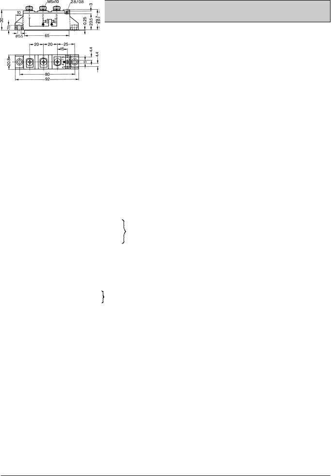
Dimensions in mm (1 mm = 0.0394")
MCC / MCD Version 1 B |
MCC Version 8 B |
MCD Version 8 B |
||
|
|
|
|
|
|
|
|
|
|
© 2000 IXYS All rights reserved |
2 - 4 |
 Loading...