


IQ100C
ITV Ice Makers IQ100C, IQ200C, IQ300C, IQ300, IQ500 Installation Manual
...
ICE QUEEN
USER MANUAL IQ MACHINES
MANUAL DEL USUARIO MÁQUINAS IQ
MANUEL DE L’ UTILISATEUR IQ MACHINES
ICE FLAKERS MAKERS
MÁQUINAS DE HIELO EN ESCAMAS
MACHINES A GLAÇONS EN CUBE
IQ100C
IQ200C
IQ300C
IQ300
IQ500
IQ900
IQ1300
IQ2700
IQ1300 REMOTE
IQ2700 REMOTE

ICE QUEEN
USER MANUAL IQ MACHINES
MANUAL DEL USUARIO MÁQUINAS IQ
MANUEL DE L’ UTILISATEUR IQ MACHINES
INDEX
WARNING 1
RECEPTION OF THE MACHINE 1
INSTALLATION 2
START-UP 6
MAINTENANCE AND CLEANING PROCEDURES 7
WIRING DIAGRAMS 9
ÍNDICE
ADVERTENCIAS 16
RECEPCIÓN DE LA MÁQUINA 16
INSTALACIÓN 17
PUESTA EN MARCHA 21
INSTRUCCIONES DE MANTENIMIENTO Y LIMPIEZA 22
ESQUEMAS ELÉCTRICOS 24
INDEX
ATTENTION 31
RECEPTION DE L’APPAREIL 31
INSTALLATION 32
MISE EN MARCHE 36
INSTRUCTIONS POUR L’ENTRETIEN ET LE NETTOYAGE 37
SCHÉMAS ÉLECTRIQUES 39

USER MANUAL IQ
THIS MANUAL IS PART OF THE PRODUCT. READ IT CAREFULLY IN ORDER TO USE AND MAINTAIN THE
EQUIPMENT CORRECTLY.
IT IS IMPORTANT TO KEEP IT FOR FUTURE TROUBLESHOOTING AND REFERENCE.
Warning
The installation of this equipment should be done by the Technical Assistance Service department.
The socket should always be placed on an accessible location.
ALWAYS disconnect the power supply from the machine BEFORE any cleaning or maintenance service.
Any change needed on the electrical installation for the appropriate connection of the machine, should be exclusively
performed by qualified and certified professional personnel.
Any use by the ice maker not intended to produce ice, using drinking water, is considered inappropriate.
It is extremely dangerous to modify or to intend to modify this machine, and shall make any type warranty void.
This appliance is not intended for used by persons (including children) with reduced physical, sensory or mental
capabilities, or lack of experience and knowledge, unless they have been given supervision or instruction concerning
use of the appliance by a person responsible for their safety.
Children should be monitored to assure that they should not play near the equipment.
This machine is not intended to be used outdoors nor exposed to the rain.
Connect the equipment to the drinking water network.
The machine should be connected using the power cable supplied with the equipment. The connection is not intended
for fixed cabling (not for the remote models, see electrical connection).
IT IS MANDATORY TO GROUND THE EQUIPMENT. To avoid possible discharges on individuals or damages to the
equipment, the machine should be grounded pursuant local and/or national regulations as the case may be.
THE MANUFACTURER SHALL BE HELD HARMLESS IN CASE OF DAMAGES ARISING DUE TO THE LACK OF THE
GROUND INSTALLATION.
In order to assure the proper operation and eciency of this equipment, it is of paramount importance to follow the
recommendations of the manufacturer, SPECIALLY THOSE RELATED TO CLEANING AND MAINTENANCE OPERATIONS,
which should be performed mostly by qualified personnel only.
CAUTION:
Do not try to perform repairs. The intervention of non-qualified personnel, besides of being dangerous, could result in
serious malfunctioning. In case of damages, contact your distributor. We recommend always using original replacement
and spare parts.
Perform all discharge and recovery of materials or waste according the national regulations in force.
Reception of the Machine
Inspect the outside packing. In case of damages, MAKE THE CORRESPONDING CLAIM TO THE CARRIER.
To confirm the existence of damages, UNPACK THE MACHINE IN THE PRESENCE OF THE CARRIER and state any
damage on the equipment on the delivery document or on a separate instrument.
As from May 1, 1998 complies with the European regulations on management of packing and packing waste, inserting
the “Green Dot Label” on all their packages.
1
USER MANUAL IQ
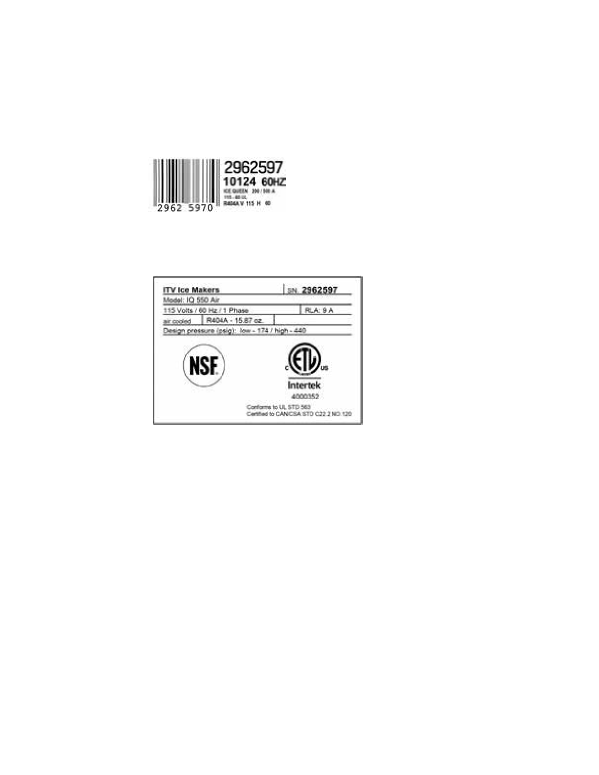
Always state the machine number and model. This number is printed on four locations:
(1) Packing: On the outside, it contains a label with the manufacturing number (1).
(2) Exterior of the equipment: On the back of the equipment, as the previous one.
(3) Nameplate: On the back of the machine.
(1)
Check that in interior of the machine the installation kit is complete and comprises:
• Ice scraper and manual.
• Warranty and serial number
• Drain hose.
CAUTION: All packing elements (plastic bags, carton boxes and wood pallets) should be kept outside the reach of
children, as they are a source of potential hazard.
Installation
THIS ICE MAKER IS NOT DESIGNED FOR OUTDOOR OPERATION.
An incorrect installation of the equipment may cause damages to individuals, animals or other materials, being
the manufacturer not responsible for such damages.
CAUTION:
The machines are designed to operate at room temperature between 5ºC (41ºF) and 43ºC (110ºF), with inlet water
temperature between 5ºC (41ºF) and 35ºC (95ºF). The gear motor is excessively forced if operated under the minimum
temperatures.
2
USER MANUAL IQ
Above the maximum temperature, the life of the compressor is shortened and the production is substantially lower.
Do not place anything over the maker or facing the front louver.
In case the front louver is not enough, the exit is either total or partially obstructed or due to its placement, it will receive
hot air from another device, we strongly recommend, in case it is not possible to change the location of the machine, to
install a water condenser.
IT IS IMPORTANT THAT THE WATER PIPING DO NOT PASS BY OR NEAR SOURCES OF HEAT SO AS NOT TO LOSE ICE
PRODUCTION.
IMPORTANT: Thread the support legs to the base of the machine on the housing set to such end, in case of machines
having this feature, and regulate the height as to have the equipment perfectly leveled.
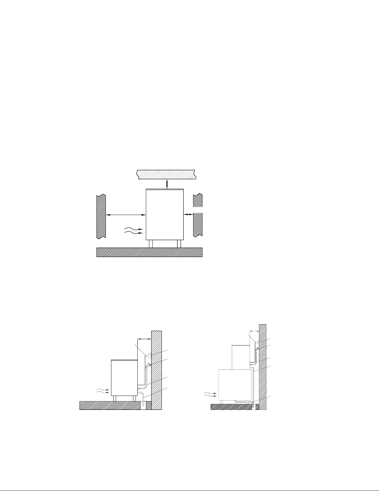
MINIMUM DISTANCE TO OBSTACLES
Side View
>75cm / >29”
* There’s no minimum distance to obstacles in the sides of the machine
CONNECTION DIAGRAM
FOR COMPACT MODELS FOR MODULAR MODELS
Plug
>10cm
>4”
>10cm / >4”
Socket
Tap
>10cm / >4”
Plug
>10cm
>4”
Socket
Tap
Water Connection Hose
Condensar Discharge Outlet
Water Connection Hose
Discharge Hose
3
Bin Drainage

USER MANUAL IQ
(1) Water and Drainage
Water quality has a remarkable influence on the appearance, hardness and flavor of the ice as well as, in the machines
condensed by water on the life of the condenser.
(2) Connections to the Water Network
Use a flexible food grade pipe.
Pressure should be established between 1 and 6 Bar (14 and 85 psi / 0.1 and 0.6 Mpa).
If pressures overpass such values, install the necessary corrective devices.
ATTENTION: The machine shall be plumbed (with adequate blackflow protection) according to applicable Federal State
and local regulations.
(3) Connection to Drainage
Drainage should be located below the level of the machine, at 150 mm (5.91 inches) minimum.
It is convenient that the drainage pipe is of 30 mm (1.18 in) of interior diameter and with a minimum gradient of 3 cm
(1.18 in) per meter (see figure).
CORRECT INCORRECT
Descending Ascending
INCORRECT
(4) Electrical Connection
IT IS MANDATORY TO GROUND THE EQUIPMENT: To avoid possible discharges on individuals or damages to the
equipment, the machine should be grounded pursuant local and/or national regulations as the case may be.
THE MANUFACTURER SHALL BE HELD HARMLESS IN CASE OF DAMAGES ARISING DUE TO THE LACK OF THE GROUND
INSTALLATION.
The machine is supplied with a 6 feet cable of length. In case the supply cable is damaged, it should be replaced by a
cable or a special kit to be furnished by the manufacturer or post-sale service. Such replacement should be performed
by qualified technical service only.
The machine should be placed in such a way as to allow a minimum space between the back and the wall to allow an
easy access and without risks to the cable plug.
It is convenient to install adequate switches and fuses.
Voltage and tension are indicated on the nameplate and in the technical specifications of this manual. Variation on
voltage above the 10% stated on the nameplate could result on damages or prevent the machine start-up.
The line up to the plug should have a minimum section of AWG16.
4
USER MANUAL IQ
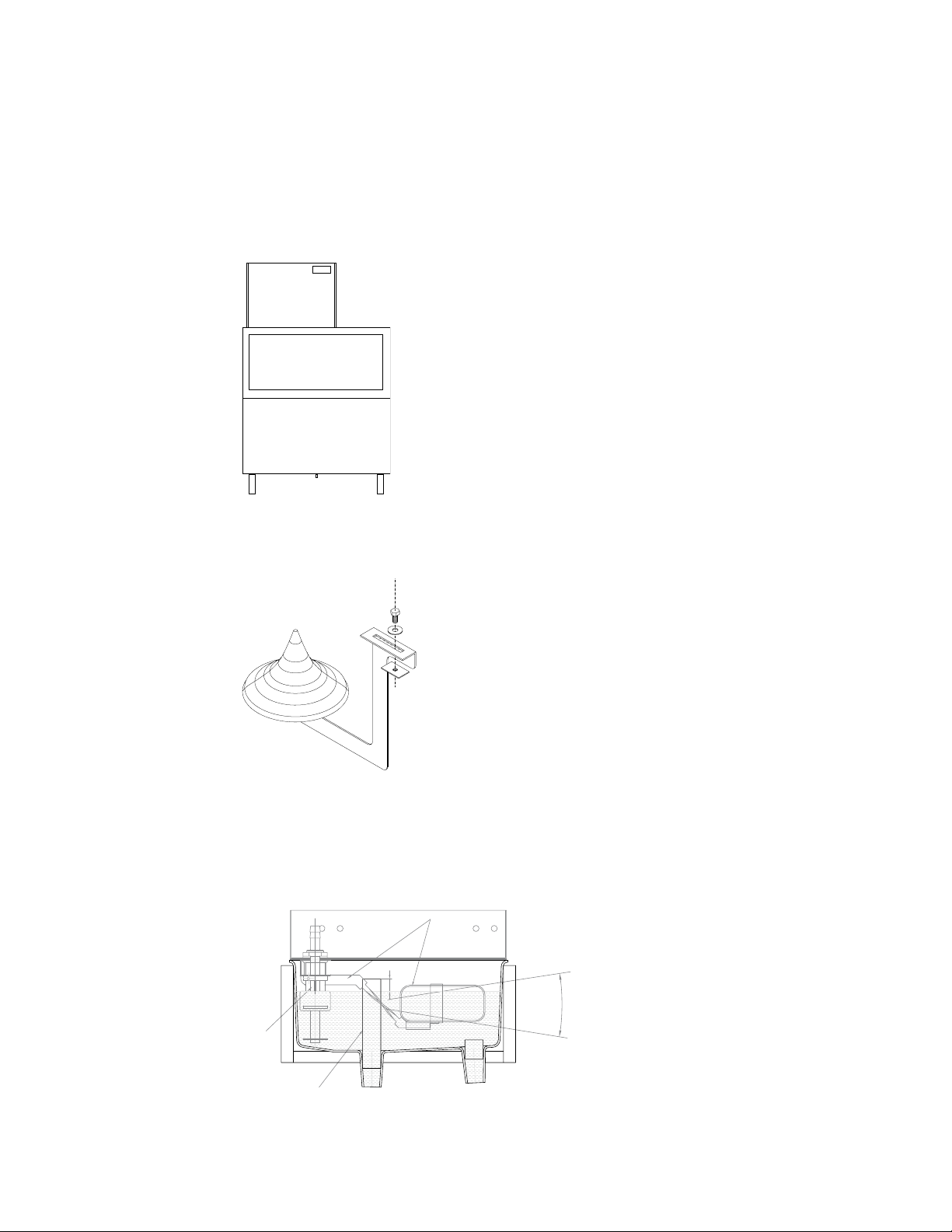
(5) Installation of Modular Equipments over Bin or Silos.
Modular makers should be installed over deposits or silos, following the instructions contained in this manual.
The resistance and stability of the container-machine/s assembly should be verified, as well as the fastening elements.
Follow bin manufacturer instructions.
(6) Assembly of the Dispersion Cone (Modular Models)
This device distributes the ice in the bin, and avoids ice compression under the exit pipe. Changing its position, the ice
could be directed to any direction.
(7) Water Level
The function of the water level is to maintain the necessary flow on the evaporator, and using the magnetic micro
device incorporated, stop the operation of the machine until the water reaches again the container.
The optimum level is located on the horizontal indicated in the figure, and its regulation is made following the indications
appearing below.
Float
Turn upwards to increase the level,
and downwards to decrease it. (Grab
from the metalic arm, NEVER FROM
THE FLOAT).
10
Probe
Safety Overflow
5
USER MANUAL IQ
(8) Remote Ice Queen Machine Installation: Connect to the Field-Installed Condensing Unit
Connect the pipes of a field-installed condensing unit (or a field-installed condenser located remote from the ice maker)
to the connections valves of the machine: the high pressure (liquid) line to the inlet connection valve (3/8” SAE) and the
low pressure (suction) line to the outlet connection valve (1/2” SAE).
Make vacuum to lines. Use allen wrench to open liquid and suction line connection valves. Unit is precharged with R404A
till positive pressure.
Connect the low pressure gauge to the service point of the KVP and, when unit started, adjust the KVP to -15ºC (2.6bar
/ 37.7psig).
(9) Remote Ice Queen Machine Installation: Connect to the Power Supply
The ice maker must be permanently connected to the power supply. There is a terminal box where the connections must
be made; it will be accessible removing the service cover of the outlet box.
All wiring must conform to local, state and national codes.
The ice machine must be grounded in accordance with national and local electrical code.
Start-Up
(1) Previous Checkup
a) Is the machine leveled?
b) Voltage and frequency are the same as those on the nameplate?
c) Are the discharges connected and operating?
d) If air condensed: Is the air circulation and its temperature appropriate?
ROOM WATER
MAXIMUM 43º C / 109º F 35ºC / 95º F
MINIMUM
e) Is water pressure appropriate?
MINIMUM 1 Bar (14 psi / 0.1 Mpa)
MAXIMUM
NOTE: In case input water pressure is higher that 6 bar (85 psi / 0.6 Mpa), install a pressure regulator.
(2) Start-Up
Once the installation instructions are followed (ventilation, site conditions, temperatures, water quality, etc.), proceed
as follows:
1) In the case of modular modules, remove the cover to access the installation kit .
2) In case of compact models, open the deposit door to access the installation kit.
3) Open the water inlet. Verify the no existence of leakages.
4) Connect the machine to the electrical network, and switch on the main switch placed on the front side..
5) For three-phase machine if sequence is not correct, red pilot will light and is necessary to change connection
sequence.
6) After 10 min. timer delay machine will start. (this delay will happen after every machine stop)
7) Verify that there are no vibrations or frictions on the elements.
8) After a few minutes, verify that the ice production has started.
9) In the case of modular models (mainly in three-phase equipments), having the cover removed, verify that the motor
is rotating in the correct direction (see arrow on steel frame).
10) Verify that after the final cycle, the frost on the aspiration pipe is at 20 mm (0.78 in) of the compressor.
5º C / 41º F
6 Bar (85 psi / 0.6 Mpa)
5ºC / 41º F
6
USER MANUAL IQ
The technical installer shall invoice traveling expenses, labour cost hours and materials used.
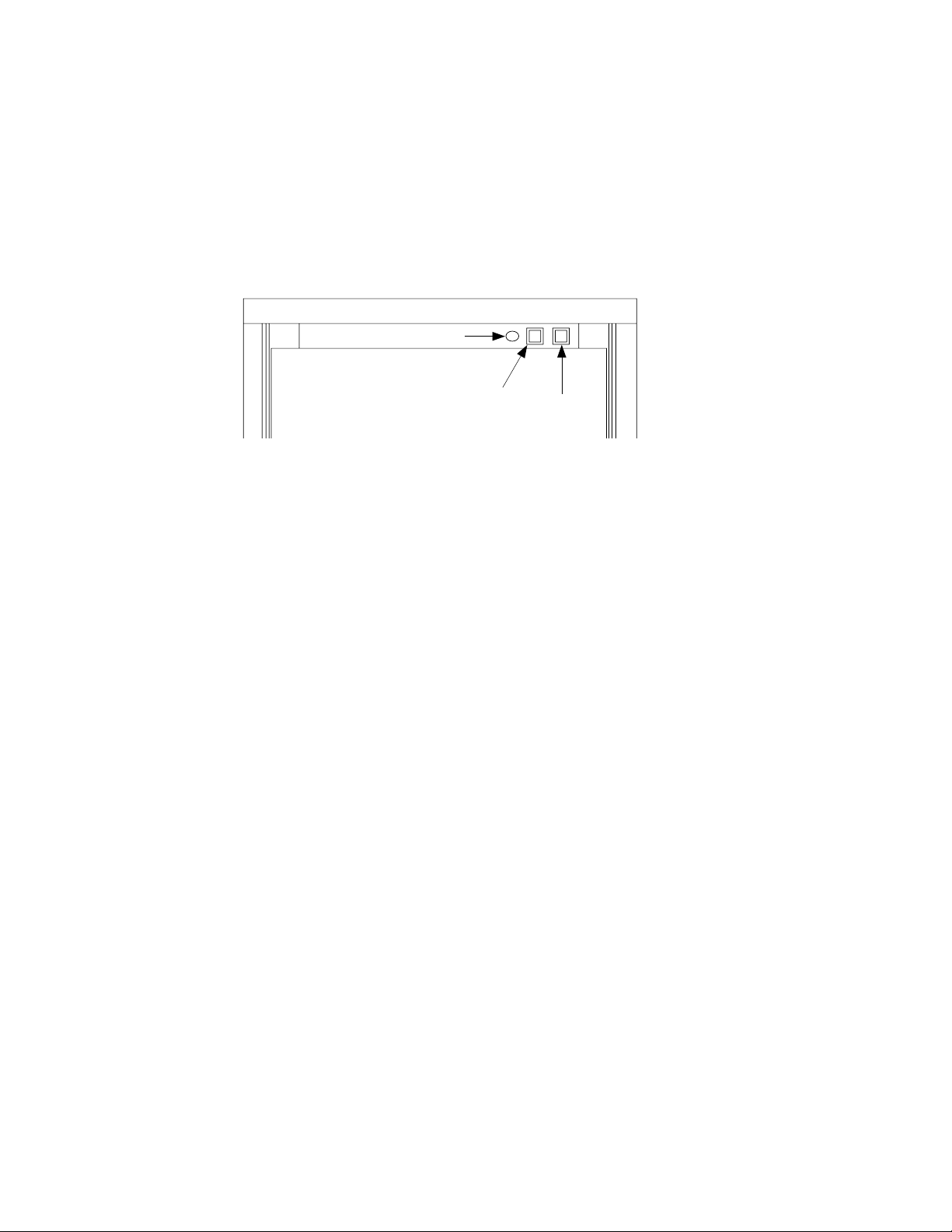
(3) Maneuver for model IQ 100C
Green led: Indicanting the machine is working. It could be stopped because the thermostat.
Black button: It starts the machine. It also re-starts the machine when it’s stopped because any safety element.
Red button: To stop the machine completely.
Green led
Black button
Red button
Maintenance and Cleaning Procedures
CAUTION: Instruct the user about maintenance, informing that maintenance and cleaning operation as well as damages
due to the lack of such operations are not included in the warranty.
If a good maintenance is performed, the machine will continue producing a good quality of ice and will be free of
damages.
Maintenance and cleaning intervals will depend on the conditions of the site and water quality.
CAUTION: At least, one revision and cleaning should be performed every six months.
On dusty environments, it might be necessary to clean the condenser on a monthly basis.
CAUTION: Unit should always be disconnected during maintenance/cleaning procedures.
CLEANING THE CONDENSER
(1) Air Condenser
1) Disconnect machine and close water faucet.
2) Remove front grid.
3) Clean condenser using a vacuum cleaner, soft brush or low pressure air. Clean from top to bottom, not side to side.
Be careful not to bend the condenser fins.
4) Carefully wipe o the fan blades and motor with a soft cloth. Do not bend the fan blades.
(2) Water Condenser
1) Disconnect machine and close water faucet.
2) Remove the front grid.
3) Disconnect water entry/exit from condenser.
4) Prepare a solution of 50% phosphoric acid in distilled water.
5) Distribute solution through condenser and make it circulate. Solution is more eective at 35°-40°C (95ºF-104ºF).
WARNING! DO NOT USE HYDROCHLORIC ACID
(3) Cleaning the Ice Bin
1) Disconnect machine, close water faucet and empty storage bin of ice
2) Wipe with a kitchen cloth soaked in bleach and detergent
3) If white lime stains do not vanish, rub with some lemon or vinegar, wait for a few minutes and wipe with the cloth
again.
4) Rinse with plenty of water, dry, and run the machine
7

USER MANUAL IQ
(4) Evaporator / Water Trough
1) Disconnect machine.
2) Remove water hose situated in lower bearing of evaporator. Use a container to collect water.
3) Allow water to flow for 2 to 3 minutes.
4) Close water faucet and replace hose in evaporator.
5) Prepare a solution of an appropriate product for the cleaning of ice machines (lime). Do not use hydrochloric acid.
We recommend the use of Scale-Kleen (Everpure) prepared according to the manufacture’s instructions. Slowly pour
solution into water trough. (Solution is more eective at 35°-40°C / 95ºF-104ºF).
6) Allow solution to stand for 20 minutes.
7) Remove lower hose and empty trough. Replace hose.
8) Fill trough with solution to maximum capacity. Connect machine and wait for unit to automatically shut o for lack
of water.
WARNING: Discard ice produced during cleaning procedure.
9) Disconnect machine, remove bearing hose and let water run.
**Sanitary cleaning
10) Replace bearing hose. Faucet must remain closed.
11) Prepare a solution of sanitizer (5-7 liters / 1.3-1.85 gal) using approved (EPA/FDA) sodium hypochlorite food
equipment sanitizer to form a solution with 100 t 200 ppm free chlorine yield. Below an example to calculate the
proper quantity of sanitizer to add to the water, for a household bleach 12,5%:
Blench to add = = 1.2 gr/L ® *0.133 = 0.16 oz/gal
15 15
% dis 12.5
12) Fill trough with solution. Connect machine and slowly add solution maintaining level in order to allow machine to
work for at least 15 minutes.
13) Empty trough and evaporator removing hose.
14) Replace hose. Open water faucet and allow machine run for 15 minutes.
WARNING: Discard ice produced during all cleaning procedure.
15) Disconnect unit, place cover and check for water leaks.
16) Replace filters if necessary. (Machines provided with 5mm wire gauze filters).
17) Reconnect machine.
(5) Cleaning the Outside of the Machine
1) Disconnect machine and close water faucet.
2) Wipe with a kitchen cloth soaked in bleach and detergent
3) If white lime stains do not vanish, rub with some lemon or vinegar, wait for a few minutes and wipe with the cloth
again.
4) Wipe with a damp cloth and then dry.
(6) Cleaning the Inlet Filters
They are easily obstructed during the first days of operation, mainly with new piping installations.
Loose the hose and clean it under water.
(7) Checking for Water Leaks
This must be done whenever maintenance is carried out on the machine: check all water connections, braces, tubes and
hoses in order to eliminate leaks and prevent breakages and flooding.
8

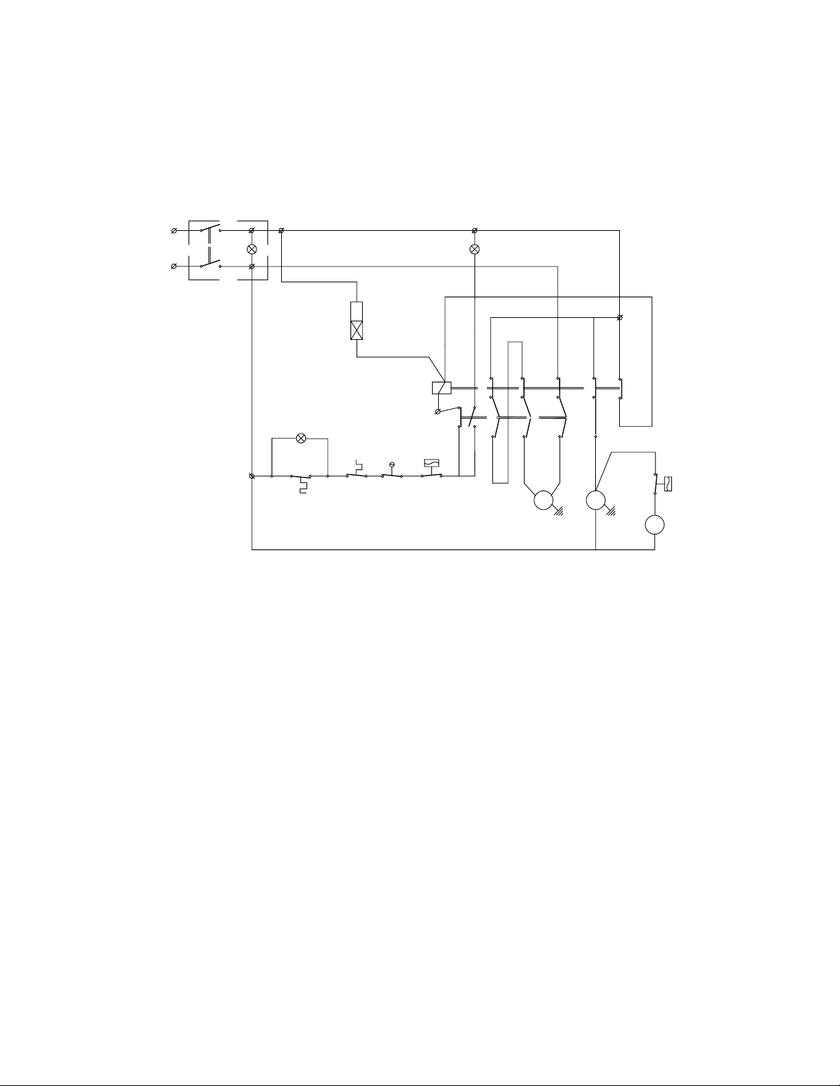
Wiring Diagrams
IQ 100C
Ps
USER MANUAL IQ
L
I
N
Components:
Pv Fan pressostat
V Fan
Ew Condenser water valve
S Compressor
Ir On switch
Is O switch
marrón/brown
Ir
13
Is
negro/black
Pt
Iw
violeta/violet
12
9
Ts
14
gris/grey
8
5
rojo/red
L
Pv
C
(1)
V
(2)
Ew
R S
azul/blue
20/01/11 . 24/10
Ts Full storage bin stop
Iw Water low level float switch
Ps High pressure safety pressostat
R Gearmotor
Pt Motor thermal protection
I Green - on
9
USER MANUAL IQ
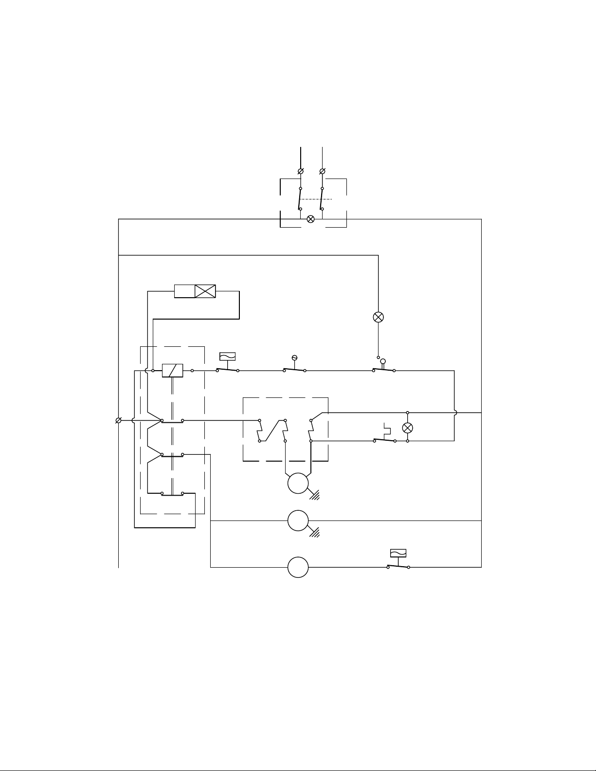
IQ 200C
Ip
N
L
I III
A1
Tem.
II
Ts
Components:
Tem Start timer
C1 Contactor
Pv Fan pressostat
V Fan
S Compressor
Ip On / O switch
Ts Full storage bin stop
Iw Water low level float switch
Ps High pressure safety pressostat
R Gearmotor
Pt Motor thermal protection
Ew Condenser water valve
I Green - on
II Yellow - full
III Thermic gearmotor
A2
A1
C1
A2
96
95
Iw Ps
Pt
LC
L1 L2 L3 L4
98
97
T1 T2 T3
gris/grey
gris/grey
marrón/brown
R
22
rojo/red
S
negro/black
3
Ca1
4
L
Pv
C
V
marrón/brown
20/01/11 . 24/10
10
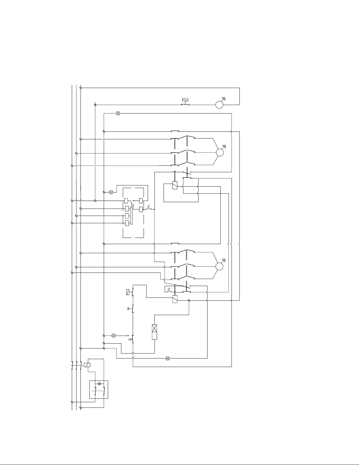
IQ - Single Phase
1
T
A1 A2
USER MANUAL IQ
L1 N
Ip
azul/blue
azul/blue
negro/black
negro/black
azul/blue
A1 A2
C1
L1
L2
L3
I
gris/grey
Ps
L C
marrón/brown
C
T1
rojo/red
C2
T2
C3
T3
rojo/red
L
1 L2 L3
T1
T2
Dis.
Iw
R
S
violeta/violet
T3
4
2
Pt
Ts
marrón/brown
1
marrón/brown
II
marrón/brown
Pv
rojo/red
V
L C
20/01/11 . 24/10
Components:
T1 Start timer
C Contactor
Dis Circuit breaker (gearmotor)
Pv Fan pressostat
V Fan
S Compressor
Ip On / O switch
Ts Full storage bin stop
Iw Water low level float switch
Ps High pressure safety pressostat
R Gearmotor
Pt Motor thermal protection
I Yellow - full
II Red - Breaker
11
USER MANUAL IQ
IQ - Three Phases
azul/blue
Pv
marrón/brown
L
C
V
20/01/11 . 24/10
II
rojo/red
Ca2
4
3
negro/black
T2 T3
L1 L2 L3
IV
rojo/red
11
12
T
Pt
14
A2
C2
T1
98
959796
A1
marrón/brown
R S
R
negro/black
marrón/brown
Ca2 Auxiliar contact feedback
I Thermic compressor
II Thermic gearmotor
III Yellow - full
azul/blue
IV Phase sequence
DF
4
3
negro/black
T2 T3
marrón/brown
959796
A1
T1
98
L1 L2 L3
C
Ps
Iw
violeta/violet
L
marrón/brownvioleta/violet
Pt
violeta/violet
A2
C1 Ca1
A2
III
azul/blue
negro/black
marrón/brown
azul/blue
gris/grey
4
Ts
T1
2
1
1
A
I
rojo/red
S
negro/black
marrón/brown
Ts Full storage bin stop
Iw Water low level float switch
Ps High pressure safety pressostat
R Gearmotor
Pt Motor thermal protection
Df Phase sequence relay
Ca1 Auxiliar contact gearmotor
marrón/brown
marrón/brown
C
A1 A2
RST
Ip
Components:
T1 Start timer
C1 Contactor (gearmotor)
C2 Contactor (compressor)
Pv Fan pressostat
V Fan
S Compressor
Ip On / O switch
12

Three Phases - IQ 2700
Ca1
3
1 L2 L3
L
A2
A1
T1
A1
C1
4
959796
A2
USER MANUAL IQ
II
Pv
L C
L
Ca2
3
4
azul/blue
T2 T3
S
rojo/red
T1
rojo/red
98
L1 L2 L3
979698
95
A2
A1
C2
V
azul/blue
T2 T3
negro/black
R
20/01/11 . 24/10
T1
negro/black
Pt
IV
L C
Ps
marrón/brown
1
11
12
T
rojo/red
14
1
marrón/brown
Iw
R S
DF
III
III
2
Ts
Ts
1
2
2
violeta/violet
violeta/violet
gris/grey
gris/grey
L C
Ps
marrón/brown
Ip
Ca2 Auxiliar contact feedback
L Electrical Interference Filter
I Thermic compressor
II Thermic gearmotor
III Yellow - full
IV Phase sequence
Ip
marrón/brown
II
Pv
L
C
L
Ca1
3
4
azul/blue
T2 T3
rojo/red
S
959796
A2
T1
rojo/red
98
I
azul/blue
L1 L2 L3
1
A2
A
T1
azul/blue
negro/black
marrón/brown
C
A1 A2
A1
C1
2
Ca
3
4
L1 L2 L3
959796
C2
A2
A1
V
azul/blue
T2 T3
negro/black
R
T1
negro/black
98
Ts Full storage bin stop
Iw Water low level float switch
Ps High pressure safety pressostat
R Gearmotor
Pt Motor thermal protection
Df Phase sequence relay
Ca1 Auxiliar contact gearmotor
Pt
RST
Ip
Components:
T1 Start timer
C1 Contactor (gearmotor)
C2 Contactor (compressor)
Pv Fan pressostat
V Fan
S Compressor
Ip On / O switch
13
 Loading...