

Page 1
2008-2011MY
WORKSHOP MANUAL
GENERAL INFORMATION
Page 2
This Workshop Manual deals only with the screen toned section(s) in the table below.
Section Sub Section
0 GENERAL INFORMATION 0A General Information
1 ENGINE 1A Engine Control System
1B Engine Mechanical
1C Engine Cooling
1D Engine Fuel
1E Engine Electrical
1F Emission Control
1G Engine Exhaust
1H Engine Lubrication
1I Engine Speed Control System
1J Induction
1K Pre-Heating System
1L Power Take-Off (PTO)
2 SUSPENSION 2A1 Air Suspension Control System
2B Front Suspension
2C Rear Suspension
2D Wheel and Tire System
3 DRIVELINE/AXLE 3A1 Front Differential
3A2 Rear Differential
3C1 Propeller Shaft
3C2 Front Axle
3C3 Rear Axle
3D Transfer Case
4 BRAKES 4A2 Brake Control System (Air Over)
4A3 Brake Control System (Full Air)
4B2 Brake (Air Over)
4B3 Brake (Full Air)
4C Anti-Lock Brake (ABS)
4C1 Anti-Lock Brake (ABS)/Anti-Slip Regulator (ASR)
4D Parking Brake
4E Hill Start Aid (HSA)
4F Speed Retarder System
4G Trailer Brake
5 TRANSMISSION/TRANSAXLE 5A Transmission Control System
5B Automatic Transmission
5C Manual Transmission
5E Clutch
5G Power Take-Off (PTO)
5G1 Side Power Take-Off
6 STEERING 6B Power Steering
7 HVAC 7A Heating and Ventilation
7B Manual Air Conditioning
7C Automatic Air Conditioning
8 RESTRAINTS 8A Seat Belt
8B Supplemental Restraint System (SRS)
8C SRS Control System
9 BODY, CAB AND ACCESSORIES 9A Lighting System
9B Wiper/Washer System
9C Entertainment
9D Wiring System
9E Instrumentation/Driver Info.
9F Body Structure
9G Cab
9H Seats
9I Security and Lock
9K Exterior/Interior Trim
9L Cab Mounting
10 CONTROL SYSTEMS 10B Vehicle Control
11 FRAME AND FRAME ACCESSORIES 11A Frame
Page 3

Page 4

General Information 0A-1
GENERAL INFORMATION
General Information
TABLE OF CONTENTS
General Information . . . . . . . . . . . . . . . . . . . . . . . 0A-2
General Repair Instructions . . . . . . . . . . . . . . . 0A-2
Identification . . . . . . . . . . . . . . . . . . . . . . . . . . . . . 0A-3
Chassis Number/Engine Number Stamping
Position . . . . . . . . . . . . . . . . . . . . . . . . . . . . . . . 0A-3
Option Code List . . . . . . . . . . . . . . . . . . . . . . . . 0A-4
Vehicle Identification Number (VIN) . . . . . . . . 0A-11
General Precaution . . . . . . . . . . . . . . . . . . . . . . 0A-15
General Precautions . . . . . . . . . . . . . . . . . . . . 0A-15
Lifting Instruction . . . . . . . . . . . . . . . . . . . . . . . . 0A-17
Lifting Instruction . . . . . . . . . . . . . . . . . . . . . . . 0A-17
Caution for The Maintenance of Electrical Parts 0A-20
Battery Cable . . . . . . . . . . . . . . . . . . . . . . . . . 0A-20
Connector Handling Requirements . . . . . . . . . 0A-20
Handling Electronic Parts . . . . . . . . . . . . . . . . 0A-23
Cable Harness . . . . . . . . . . . . . . . . . . . . . . . . 0A-23
Regarding The Scan Tool. . . . . . . . . . . . . . . . . . 0A-25
Trouble Diagnosis Using The Scan Tool . . . . . 0A-25
Recommended Liquid Gasket . . . . . . . . . . . . . . 0A-31
Recommended Liquid Gasket. . . . . . . . . . . . . 0A-31
Recommended Thread Locking Agent. . . . . . . . 0A-33
Recommended Thread Locking Agent . . . . . . 0A-33
Maintenance Schedule. . . . . . . . . . . . . . . . . . . . 0A-34
Introduction . . . . . . . . . . . . . . . . . . . . . . . . . . . 0A-34
Maintenance Schedule
(for Euro4 specification except Europe) . . . . . 0A-35
Maintenance Schedule
(for Euro2, Euro3 specification). . . . . . . . . . . . 0A-41
Maintenance Schedule (for Europe) . . . . . . . . 0A-45
Maintenance Schedule
(CNG engine for Australia) . . . . . . . . . . . . . . . 0A-50
Maintenance Schedule
(CNG engine for Thailand) . . . . . . . . . . . . . . . 0A-54
Transmission Oil - ZF6S1000/ZF9S1110 Type 0A-58
Transmission Oil - FS8209A/FSO5206B Type 0A-65
RS23/RS40 Type Axle . . . . . . . . . . . . . . . . . . 0A-67
RS25 Type Axle . . . . . . . . . . . . . . . . . . . . . . . 0A-68
Maintenance Schedule for Severe-condition . . . 0A-69
Introduction . . . . . . . . . . . . . . . . . . . . . . . . . . . 0A-69
Maintenance Schedule for Severe-condition . 0A-69
Recommended Fluids, Lubricants and
Diesel Fuels (except Europe). . . . . . . . . . . . . . . 0A-73
Introduction . . . . . . . . . . . . . . . . . . . . . . . . . . . 0A-73
Diesel Engine Crankcase with DPD
(Low Ash Oil). . . . . . . . . . . . . . . . . . . . . . . . . . 0A-73
Diesel Engine Crankcase without DPD. . . . . . 0A-74
CNG Engine Crankcase (for Australia) . . . . . . 0A-74
CNG Engine Crankcase (for Thailand) . . . . . . 0A-74
Manual Transmission (MZX/MZW/MLD
models), Transfer Case, Differential
(without LSD) and Oil Lubricated Hub
Bearing . . . . . . . . . . . . . . . . . . . . . . . . . . . . . . 0A-75
Manual Transmission (MZZ models). . . . . . . . 0A-75
Differential (with LSD) . . . . . . . . . . . . . . . . . . . 0A-75
Smoother Clutch Oil (Smoother) . . . . . . . . . . . 0A-75
Automatic Transmission, Power Steering . . . . 0A-76
Center Bearing, Clutch Shift Block,
Grease Lubricated Hub, Water Pump,
Propeller Shaft Sliding Yoke, Universal
Joint (Multi Purpose Grease) . . . . . . . . . . . . . 0A-76
Multi-Purpose Grease Containing
Molybdenum . . . . . . . . . . . . . . . . . . . . . . . . . . 0A-76
Engine Cooling System . . . . . . . . . . . . . . . . . . 0A-76
Electric-hydraulic Cab Tilt Pump . . . . . . . . . . . 0A-77
Clutch and Brake Fluid Reservoir . . . . . . . . . . 0A-77
Diesel Fuel / Applicable Standard . . . . . . . . . . 0A-77
Diesel Fuel / Applicable Standard
(Sulfur content below 50 ppm) . . . . . . . . . . . . 0A-78
Recommended Fluids, Lubricants and
Diesel Fuels (for Europe) . . . . . . . . . . . . . . . . . . 0A-79
Introduction . . . . . . . . . . . . . . . . . . . . . . . . . . . 0A-79
Diesel Engine Crankcase with DPD
(Low Ash Oil). . . . . . . . . . . . . . . . . . . . . . . . . . 0A-79
Diesel Engine Crankcase without DPD. . . . . . 0A-79
Manual Transmission (MZX/MZW/MZZ/MLD
models), Differential (without LSD) and Oil
Lubricated Hub Bearing . . . . . . . . . . . . . . . . . 0A-80
Differential (with LSD) . . . . . . . . . . . . . . . . . . . 0A-80
Smoother Clutch Oil (Smoother) . . . . . . . . . . . 0A-80
Power Steering . . . . . . . . . . . . . . . . . . . . . . . . 0A-80
Center Bearing, Clutch Shift Block,
Grease Lubricated Hub, Water Pump,
Propeller Shaft Sliding Yoke, Universal
Joint (Multi Purpose Grease) . . . . . . . . . . . . . 0A-81
Engine Cooling System . . . . . . . . . . . . . . . . . . 0A-81
Electric-hydraulic Cab Tilt Pump . . . . . . . . . . . 0A-81
Clutch and Brake Fluid Reservoir . . . . . . . . . . 0A-82
Diesel Fuel / Applicable Standard . . . . . . . . . . 0A-82
Diesel Fuel / Applicable Standard
(Sulfur content below 50 ppm) . . . . . . . . . . . . 0A-82
Oil Viscosity Chart . . . . . . . . . . . . . . . . . . . . . . . 0A-83
Oil Viscosity Chart . . . . . . . . . . . . . . . . . . . . . . 0A-83
Lubrication Chart . . . . . . . . . . . . . . . . . . . . . . . . 0A-84
Lubrication Chart . . . . . . . . . . . . . . . . . . . . . . . 0A-84
Greasing Point . . . . . . . . . . . . . . . . . . . . . . . . . . 0A-97
Greasing Point . . . . . . . . . . . . . . . . . . . . . . . . 0A-97
Page 5

0A-2 General Information
General Information
General Repair Instructions
1. Park the vehicle on level ground and chock the
front or rear wheels before lifting the vehicle.
2. Use covers on the vehicle body, seats, and floor to
prevent damage and/or contaminations.
3. Disconnect the grounding cable from the battery
before performing service operations.
This will prevent cable damage or burning due to
shortcircuiting.
4. Raise the vehicle with a jack set against the axle or
the frame.
5. Support the vehicle on chassis stands.
6. Handle brake fluid and antifreeze solution with
great care.
Spilling these liquids on painted surfaces will
damage the paint.
7. The use of the proper tool(s) and special tool(s)
where specified is efficient, reliable, and safe
service operations.
8. Always use genuine ISUZU replacement parts.
9. Discard used cotter pins, gasket, O-rings, oil seals,
lock washers, and self-locking nuts at disassembly.
Normal function of these parts cannot be
guaranteed if they are reused.
10. Keep the disassembled parts neatly in groups.
This will facilitate smooth and correct reassembly.
11. Keep fixing nuts and bolts separate.
Fixing nuts and bolts vary in hardness and design
according to installation positions.
12. Clean all parts before inspection or reassembly.
13. Clean the oil ports and other openings with
compressed air to make certain that they are free
of dirt and obstructions.
14. Lubricate the rotating and sliding faces of all
moving parts with oil or grease before installation.
15. Use the recommended liquid gasket to prevent
leakage.
16. Be sure to tighten nuts and bolts to the specified
torque, using a properly maintained torque wrench.
17. When service operation is completed, male a final
check to be sure service has been done properly
and problem has been corrected.
18. When removing or replacing parts that require
refrigerant to the discharged from the Air
conditioning system, be sure to use the ACR4 or
equivalent to recover and recycle Refrigerant 134a (HFC-134a), to promote the movement for
the protection of the ozone layer covering the
earth.
19. To assure safety, always slowly release air
pressure from the air tanks before disconnecting
pipes, hoses or other parts from any unit under
pressure.
20. Prior to start the welding work, the following
operations are required:
• Disconnect all connectors of electronic control
unit.
• Disconnect battery ground terminal.
• Welding machine ground cable must be
connected near the welding point.
• Turn off the all switches.
Page 6
Identification
General Information 0A-3
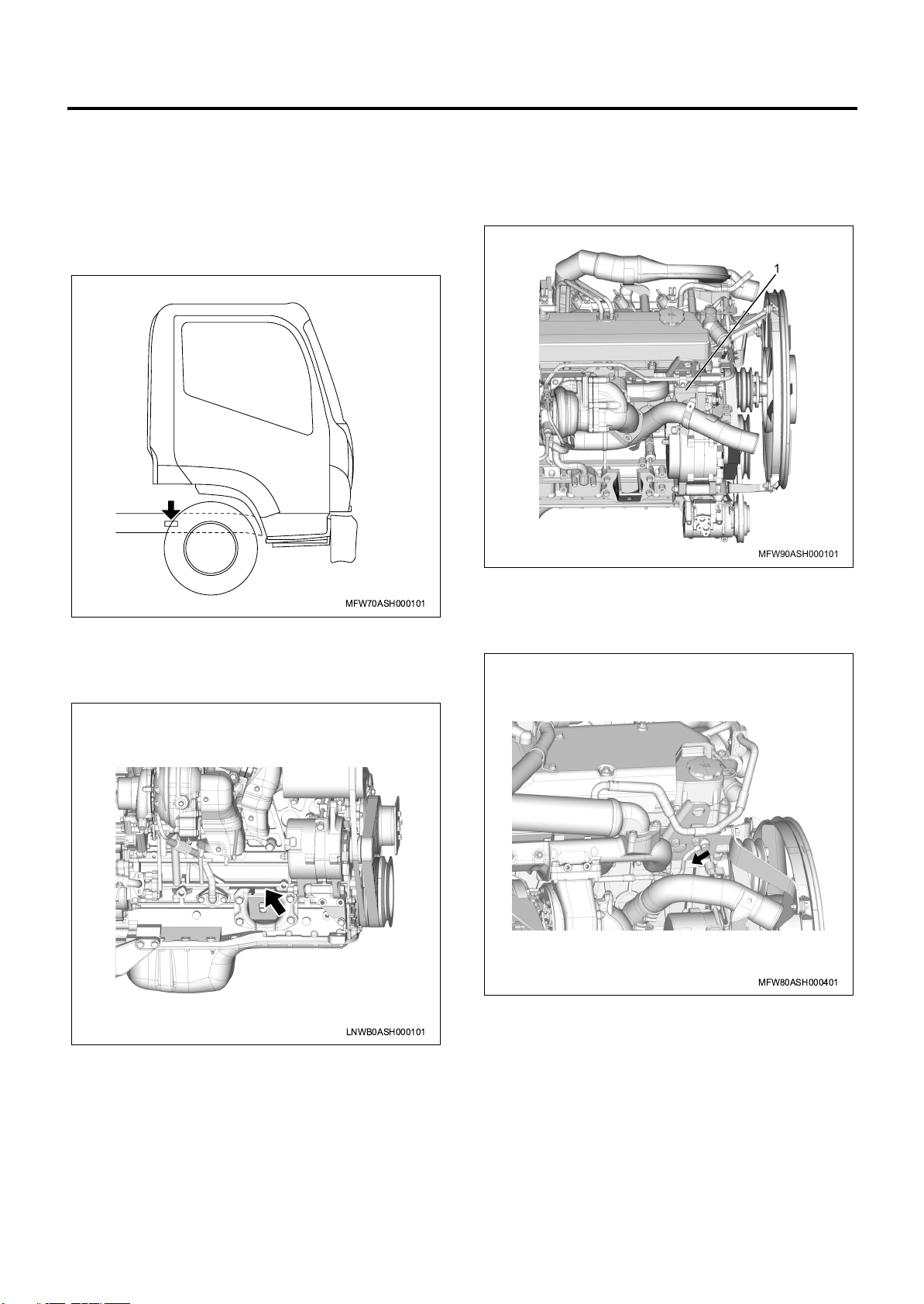
Chassis Number/Engine Number Stamping Position
Chassis number
It is stamped on the front right-hand side face of the
chassis side member.
MFW70ASH000101
Engine number (4HK1 Engine)
The engine number is stamped on the right side of the
cylinder body.
Engine number (6HF1 Engine)
The engine number (1) is stamped on the right side of
the cylinder body.
1
MFW90ASH000101
Engine number (6HK1 Engine)
The engine number is stamped on the right side of the
cylinder body.
LNWB0ASH000101
MFW80ASH000401
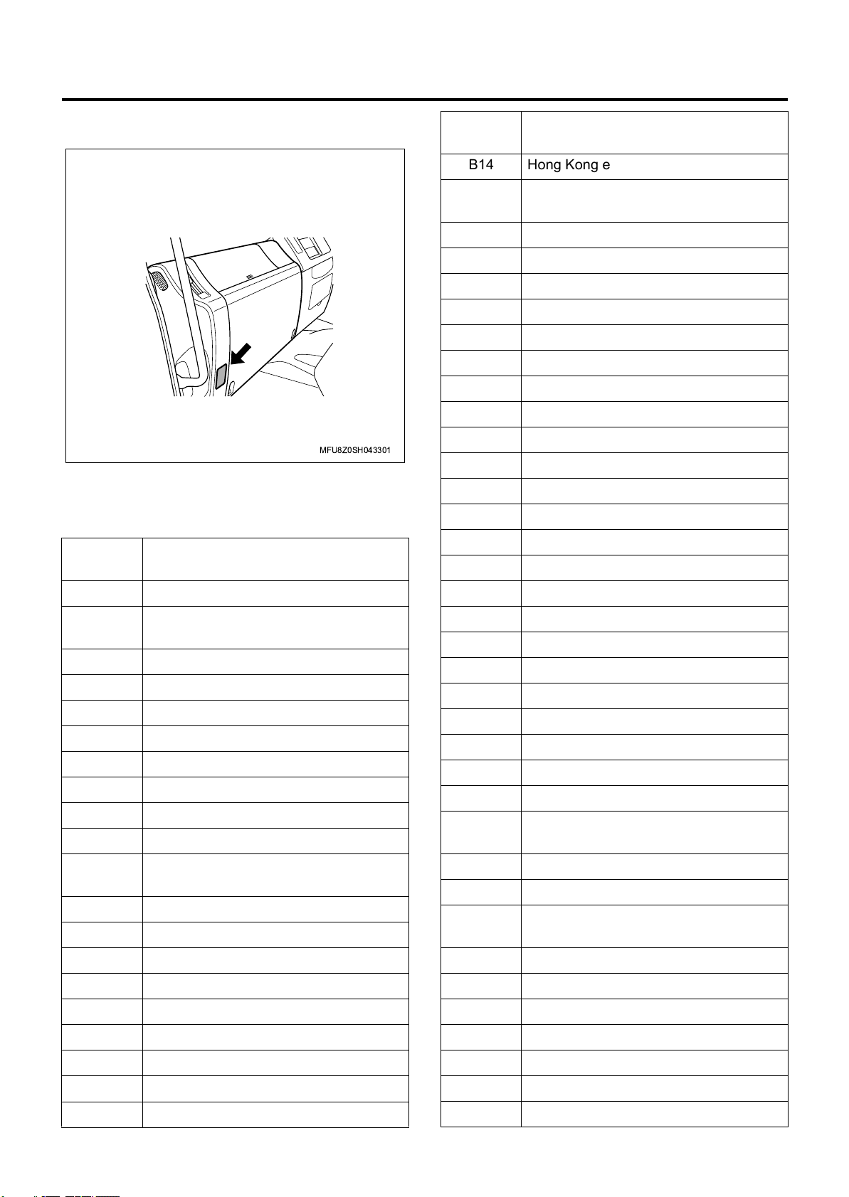
Service Parts ID Plate
The service parts ID plate is attached to the passenger
side lower dashboard.
The service parts ID plate has the following information;
• Vehicle identification number (VIN)
• Wheelbase dimensions
• Paint information
• Production options or special equipment installed
on the vehicle at the factory
Page 7
0A-4 General Information
Refer to the service parts ID plate when ordering
replacement parts.
MFU8Z0SH043301
Option Code List
Option
Code
B14 Hong Kong equipment
B3A
B30 Floor carpet - vinyl
B84 Body side molding
CB7 Colombia equipment
CE4 Head lamp washer
CGA Morocco equipment
CJ6 Country - Ireland
CK1 Pakistan equipment
CL1 Kenya equipment
CT6 Country - Italy
CU9 Country - United Kingdom
CV4 Country - Israel
CX6 Country - New Zealand
Rear wheel parking brake - air
control
Option Description
Option
Code
AJ3 Driver side air bag
AK3
AK5 Driver and passenger side air bag
AU4 Automatic door lock
A31 Power window - front & rear door
A32 Power window - front door
A56 Driver seat - air suspension
A83 Vinyl seat with reclining
BDM Power take off - transmission rear
BFK Transfer TF56
BHW
BJR Brake adjuster - manual
B02 South Africa equipment
Front seat belt & shoulder
with retractor
Power take off - engine rear,
electromagnetic clutch
Option Description
C13 Wiper with intermittent
C2C Transmission oil cooler
C2M Propeller shaft - P60 type
C3N Final differential lock
C3U Air suspension - high control
C4M Air breather with flex hose
C4Z Propeller shaft - P46 type
C41 Heater & defroster
C5K Hub lubrication - oil bath
C5T Propeller shaft - P90 type
C60 Manual air conditioning
C65
C68 Automatic air conditioning
DH2 O/S rear view mirror - long arm
DL8
Manual air conditioning
without heater core
O/S rear view mirror - remote control
with heated
B03 Thailand equipment
B04 Taiwan equipment
B1S Parking brake drum - 8.5 inch
B1T Parking brake drum - 10 inch
B10 Malaysia equipment
B12 Russia equipment
B13 Australia equipment
DNB O/S rear view mirror - pillar mounted
D20 Assist side sun visor
D31 Rear view mirror
D37 Mirror - Outside rear view
D6M User - export government
D8T Iran equipment
D94 Touch-up paint
Page 8
General Information 0A-5
Option
Code
EAK
EBB Digital tachograph
EBE Front under run protector
ECF Speed limiter - 60km/h
ECY Speed limiter - 70km/h
EDG Header console - driver & assist
EDH Round curtain rail
EDW Speed limiter - 80km/h
EDX Speed limiter - 85km/h
EFE Regulation ECE R29
EFK Floor mat - vinyl mat Var.2
E09 Europe equipment
E11 Mexico equipment
E13 New Zealand equipment
E2N Fuel pipe - steel
E29 Auxiliary steps
E40 Sleeper cab with mattress
E46 Ecuador equipment
FJC
F59 Front stabilizer
GH3 Saudi Arabia equipment
GL6 Rear shock absorber
GN1 Rear stabilizer
G86 Limited slip differential - no spin
JAQ Lighting system - Saudi Arabia
JBF Tire - KD special
JBZ Lighting system - Japanese standard
JCA Anti-noise equipment - ECE R51.02
Disc wheel - 6 studs 19.5x6.75
(136-12)
Disc wheel - 10 studs 20x8.50V
(138-13)
Option Description
Option
Code
K30 Auto cruise
K44 Generator 24V-90A
K89 Generator 24V-50A
M9A Owners manual - Not required
NCR Memory system - Runnig condition
NF7 Fuel tank 200L + 200L
NJW Ireland KD special
NMJ Speed limiter - 90km/h
NMU Speed limiter - 100km/h
NNR 3 speaker system
NT2 Emission system - Euro2
NT3 Emission system - Euro3
NT4 Emission system - Euro4
N02 Fuel tank 100L - frame side mount
N05 Fuel tank cap with key lock
N19 Fuel tank - 140L frame side
N20 Fuel tank 200L - frame side mount
N79 Spare disc wheel
PM1 Rear hook - double
PP7 Pintle hook
PR2 Driving position - wide leg space
PS7 Air dryer
PT1
PT6 Thailand KD special
P10 Spare tire carrier - frame rear mount
P13 Spare tire carrier - frame side mount
P38 Tire delete
QM8
Disc wheel - 8 studs 22.5x6.75
(145-11)
Disc wheel - 10 studs 22.5 x 8.25
(165-13)
Option Description
JDN Compartment - I/P assist side with lid
JDP Compartment - I/P assist side without lid
JE5 Anti-lock brake system
J55 Brake system - heavy duty Var.1
J91 Trailer brake control
KC5 Receptacle - accessory
KE1 Chile equipment
KF0 Fuel filter - low quality
KG2 Generator 24V60A
Q47
Q87
Q5T Turbo - conventional
Q50
Q54
Q58 Disc wheel - 10 studs 20x7.00T
Disc wheel - 8 studs 20x6.50T
(145-10)
Disc wheel - 10 studs 22.5x7.50
(162-12)
Disc wheel - 8 studs 20x6.50T
(152-11)
Disc wheel - 8 studs 20x7.00T
(162-12)
Page 9
0A-6 General Information
Option
Code
Q62
Q64 Disc wheel - 10 studs 20 x 7.50V
Q87
RC4 Dump control lever
RC5 Tool box with key lock
RE3 Spare tire fixing
RE9
RDV 4HK1-TCC engine
RJS 4HK1-TCS engine
RQZ G.V.W. - 8.0-11.0 ton
RRA G.V.W. - 11.0-14.0 ton
RR9 O/S rear view mirror - under
RSA Manual transmission - MZZ6W
RSW Manual transmission - MZX6P
RSZ Manual transmission - MZW6P
RWE Chevrolet brand
Disc wheel - 8 studs 20x7.50V
(165-13)
Disc wheel - 10 studs 22.5x7.50
(162-12)
Clutch - 15 inch single plate
strap drive
Option Description
Option
Code
SDF Room lamp with all door switch
SDH Fuel tank 400L
SDK Cab suspension - semi floating type
SDP
SEG
SFC
SFT Electric outlet - one
SGA Front under spoiler delete
SGX Vietnam equipment
SG4 Tire inflator device
SG7
SH5
SJA Driver seat - Isringhausen
SKU
Disc wheel - 8 studs 20x7.00T
(152-12)
Disc wheel - 8 studs 205x7.50V
(130-13)
Disc wheel - 6 studs 17.5x6.75
(137-10)
Disc wheel - 6 studs 16x6.00GS
(135-9)
Power take off - transmission side
without lever
Disc wheel - 8 studs 22.5x7.50
(162-13)
Option Description
R32 KD frame
R46 Spare tire & disc wheel
R9A Service cab with electric
R9B Service cab without electric
R9C Deletion - service cab with electric
R9D Deletion - service cab without electric
R9E Service cab conversion with electric
R9F
R9Z Thailand localization spec.
SAQ Front suspension - multi leaf spring
SAR Front suspension - taper leaf spring
SAS Rear suspension - multi leaf spring
SAU
SAY Standard cab
SAZ Ventilator & defroster
Deletion - service cab conversion
without electric
Rear helper suspension - taper leaf
spring
SKV
SK4 Engine overrun buzzer
SLB Front bumper with headlamp
SLC Lighting system - ECE
SLK Anti-noise equipment - ECE
SMS Rear bumper - steel wide
SP9 Assist seat without center seat
SR6 Rearward double tire
SV6 Power take off control
SY8 Spare tire carrier - lifting type
TAF
TAK Anti-noise equipment - Var.2
TAZ Driver seat - rigid without arm rest
TDU Brake regulation - ADR
TDV Brake regulation - ECE
Disc wheel - 8 studs 22.5 x 8.25
(165-13)
O/S rear view mirror - under & side
under
SBB
SBG
Disc wheel - 8 studs 20x6.00S
(135-10)
Disc wheel - 6 studs 17.5x6.00
(135-9)
TEC Roof marker lamp
TEE
TFD Cab all painting
Disc wheel - 8 studs 19.5x6.75
(147-12)
Page 10
General Information 0A-7
Option
Code
TFN
TGL Anti corrosion package
TM1 Battery - 80D26L
TR6 Headlamp leveling system - manual
TR7 Headlamp leveling system - automatic
TT5 Halogen headlamp
TT6 High intensity discharge headlamp
T1A
T62 Battery - dry
T64 Battery delete
T79 Rear fog lamp
T87 Cornering lamp
T96 Front fog lamp
UC1 Speedometer - miles per hour (MPH)
UC9 Tachograph- Kienzle
UF3 Map lamp
UG3 Engine oil temperature gauge
Driver’s seat belt with pre-tension
reducer
Injection pump Q set - special
+5%Q
Option Description
Option
Code
WC7 Tachograph - 140km/h
WF6
WG3 Brake system - heavy duty Var.2
WH2 Spare tire - front tire
WJ7 Cautions - Arabian
WJ8 Cautions - French
WL5 Inspection lamp
WM3 Interior trim - full trimming
WV2 Automatic cab tilt
WX8 Shift control - assister
W02 Highland zone package
W1G
W1H
W1J
W1K
Clutch - 14 inch single plate
strap drive
Final drive gear ratio - 6.143 (43/7)
14.5 inch hypoid
Final drive gear ratio - 5.571 (39/7)
14.5 inch hypoid
Final drive gear ratio - 6.500 (39/6)
14.5 inch hypoid
Final drive gear ratio - 6.833 (41/6)
14.5 inch hypoid
Option Description
UL5 Radio delete
UT3 AM/FM radio with CD player
U01 Roof marker - 5 lamps
U18 Speedometer - kilometer
U69 AM/FM radio
U95 2 speaker system
VG7
VP1 Front under spoiler
VR7 Two eye rear hook
VTK Owners manual - Arabic language
VTL Owners manual - French language
VTS Owners manual - Spanish language
VT7 Owners manual - English language
VZA VIN model year - 2010
VZB VIN model year - 2011
V22 Radiator grille - chrome
Front bumper reinforcement
- heavy duty
W1L
W1R
W1T
W1U
W12 Front locking hub - manual
W14 Deluxe cab
W16 Cab suspension - full floating
W18 Transfer TF36
W20 Disc wheel special painted (white)
W3B
W3D
W3F
Final drive gear ratio - 6.500 (39/6)
16.5 inch hypoid
Final drive gear ratio - 6.143 (43/7)
15.5 inch hypoid
Final drive gear ratio - 6.500 (39/6)
15.5 inch hypoid
Final drive gear ratio - 4.875 (39/8)
14.5 inch hypoid
Final drive gear ratio - 5.571 (39/7)
16.5 inch hypoid
Final drive gear ratio - 4.875 (39/8)
18.5 inch hypoid
Final drive gear ratio - 6.167 (37/6)
18.5 inch hypoid
V4F Chassis for fire car
V76 Hook - tow
WB7 Electrical horn
W3G
W3K
Final drive gear ratio - 6.667 (40/6)
18.5 inch hypoid
Final drive gear ratio - 5.571 (39/7)
15.5 inch hypoid
Page 11
0A-8 General Information
Option
Code
W3L
W3M
W3N
W3P
W3S
W3U
W3X
W3Y
W3Z
W4A
W4B
Option Description
Final drive gear ratio - 6.143 (43/7)
16.5 inch hypoid
Final drive gear ratio - 5.125 (41/8)
18.5 inch hypoid
Final drive gear ratio - 4.556 (41/9)
18.5 inch hypoid
Final drive gear ratio - 5.125 (41/8)
16.5 inch hypoid
Final drive gear ratio - 5.857 (41/7)
15.5 inch hypoid
Final drive gear ratio - 7.167 (43/6)
17.5 inch hypoid
Final drive gear ratio - 6.429 (45/7)
17.5 inch hypoid
Final drive gear ratio - 6.143 (43/7)
17.5 inch hypoid
Final drive gear ratio - 5.571 (39/7)
17.5 inch hypoid
Final drive gear ratio - 5.125 (41/8)
17.5 inch hypoid
Final drive gear ratio - 4.875 (39/8)
17.5 inch hypoid
Option
Code
W6M
W6N
W6R
W6S
W66 Disc wheel with step
W71 Cab suspension - rigid type
W8C
W8D
W8F
W8L
X5J Manual transmission - MLD6Q
X7W Manual transmission - MLD6S
X9C Transmission - manual
Final drive gear ratio - 6.43 (45/7)
18.0 inch hypoid Rockwell
Final drive gear ratio - 6.83 (41/6)
18.0 inch hypoid Rockwell
Final drive gear ratio - 4.30 (43/10)
18.0 inch hypoid Rockwell
Final drive gear ratio - 6.14 (43/7)
15.0 inch hypoid Rockwell
Final drive gear ratio - 4.56 (41/9)
18.0 inch hypoid Rockwell
Final drive gear ratio - 6.43 (45/7)
15.0 inch hypoid Rockwell
Final drive gear ratio - 4.555 (41/9)
14.5 inch hypoid
Final drive gear ratio - 6.83 (41/6)
15.0 inch hypoid Rockwell
Option Description
W4C
W4F
W4H
W4T
W4W
W4X
W5M
W5V
W5Z
W6A
W6B
W6C
Final drive gear ratio - 4.556 (41/9)
17.5 inch hypoid
Final drive gear ratio - 5.125 (41/8)
14.5 inch hypoid
Final drive gear ratio - 5.125 (41/8)
15.5 inch hypoid
Final drive gear ratio - 4.333 (39/9)
18.5 inch hypoid
Final drive gear ratio - 6.833 (41/6)
17.5 inch hypoid
Final drive gear ratio - 4.333 (39/9)
14.5 inch hypoid
Final drive gear ratio - 4.100 (41/10)
14.5 inch hypoid
Final drive gear ratio - 6.833 (41/6)
16.5 inch hypoid Rockwell
Final drive gear ratio - 4.89 (44/9)
18.0 inch hypoid Rockwell
Final drive gear ratio - 5.38 (43/8)
18.0 inch hypoid Rockwell
Final drive gear ratio - 5.63 (45/8)
18.0 inch hypoid Rockwell
Final drive gear ratio - 6.14 (43/7)
18.0 inch hypoid Rockwell
X9D Transmission - automatic
YC4
YK3 Rearward single tire
YM9 Reversing warning buzzer
YN1 Caution - Spanish
YS1 O/S rear view mirror - flat type
YT9 Pakistan KD special
Y2C Manual transmission - MLD6W
Y21 Light duty package truck
Y3A
Y3B
Y4F
Y4G
Y4V
Y48 Heavy duty package truck
Y5D Manual transmission - ZF 6S1000
Injection pump - high altitude
compensator, aneroid type
Manual transmission
- Fuller FS8209
Automatic transmission
- Allison MD3560P
Automatic transmission
- Allison LCT2000
Automatic transmission
- Allison MD3060P
Manual transmission
- Fuller FSO5206B
Page 12
General Information 0A-9
Option
Code
Y5E Manual transmission - ZF 9S1110
Z05
Z06 Brake system - full air dual circuit
Z1V Equipment - additional key
01D KD package - South Africa
01R Tire - front & rear 8.25-20-14 lug
02E KD package - Taiwan
05R Tire - front & rear 8.25R20-14 rib
09X
1D7 6HF1-TCN engine
1D9 6HF1-TCC engine
10T Tire - front & rear 9.00-20-14 rib
10X
Brake system - air over hydraulic
dual circuit
Tire - front 8.25-20-14 rib,
rear 8.25-20-14 lug
Tire - front 9.00-20-14 rib,
rear 9.00-20-14 lug
Option Description
Option
Code
42W Wheel base 4,200mm
43P Tire - front & rear 9R22.5-14
43W Wheel base 4,300mm
45N Tire - front & rear 11R22.5-14 rib
45P Tire - front & rear 275/70R22.5
45R Tire - front & rear 10.00R20-14 rib
46W Wheel base 4,600mm
48W Wheel base 4,800mm
49W Wheel base 4,900mm
49P
5D9
5E0
5E1 Tire - front & rear 10R22.5-14
Tire - front & rear 8.25R20-14
exp block
Tire - front & rear
295/80R22.5-152/148K rib/lug
Tire - front & rear
295/80R22.5-152/148J rib
Option Description
11X
12X
15N Tire - front & rear 9R22.5-14 rib
155 Interior color - Charcoal gray
2G0 Singapore equipment
20D Thailand KD deletion parts
21R Tire - front & rear 9.00-20-14 lug
25R Tire - front & rear 9.00R20-14 rib
27X
30T Tire - front & rear 10.00-20-14 rib
34W Wheel base 3,400mm
35N Tire - front & rear 10R22.5-14 rib
36W Wheel base 3,600mm
37W Wheel base 3,700mm
38W Wheel base 3,800mm
39W Wheel base 3,900mm
40S Tire - front & rear 8.25-16-14 rib
40T Tire - front & rear 10.00-20-16 rib
Tire - front 10.00-20-14 rib,
rear 10.00-20-14 lug
Tire - front 10.00-20-16 rib,
rear 10.00-20-16 lug
Tire - front 11.00-20-16 rib,
rear 11.00-20-16 lug
5G2
5H1
5J6
5J7
5J8 Tire - front & rear 245/70R19.5 rib
5J9 Tire - front & rear 235/75R17.5 rib
5K0 Tire - front & rear 265/70R19.5 rib
5K4
5K5
5L1 Tire - front & rear 12.00R20-18
5L4
5L7
5L8 Tire - front & rear 10.00R-20-16 lug
5N5
Tire - front 295/80R22.5,
rear 11R22.5-16
Tire - front 10.00-20-16 rib,
rear 10.00-20-16 lug
Tire - front 9.5R17.5 129/127L rib,
rear 9.5R17.5 129/127L traction
Tire - front & rear 11R22.5 148/145L
rib
Tire - front & rear 11R22.5 148/145K
rib/lug
Tire - front & rear 12R22.5 152/148K
rib/lug
Tire - front & rear 275/70R22.5
148/145M rib
Tire - front & rear 9.00R-20-14
exp lug
Tire - front & rear 265/70R19.5 140/
138M rib (BS brand)
40W Wheel base 4,000mm
41R Tire - front & rear 10.00-20-14 lug
41W Wheel base 4,100mm
5N6
5P0
Tire - front & rear 235/75R17.5 132/
130M rib (BS brand)
Tire - front & rear 235/75R17.5 132/
130M rib (BS brand)
Page 13
0A-10 General Information
Option
Code
5P1
5P2
5P3
5P6 Tire - front & rear 225/70R19.5
5P7
50W Wheel base 5,000mm
51R Tire - front & rear 10.00-20-16 lug
51W Wheel base 5,100mm
517 Body color - AL. gray
53W Wheel base 5,300mm
538 Body color - Tool-IPEC yellow
55N Tire - front & rear 11R22.5-16 rib
55P
55R Tire - front & rear 10.00R20-16 rib
55W Wheel base 5,500mm
58N Tire - front & rear 11.00R20-16 rib
58W Wheel base 5,800mm
59W Wheel base 5,900mm
6DY Rear under run protector
6EP HSA system
6HF KD preparatory package
6KK Horn - heavy duty (dual)
6ND OK window
6NF Remote control door lock
6PH
6SZ Power take off - flywheel
6UC Fluorescent lamp
6UH
6VE O/S rear view mirror - door mount
6WX Floor mat - vinyl
6XH ASR system
60W Wheel base 6,000mm
609 Body color - FT orange
Tire - front 295/80R22.5,
rear 11R22.5-16 (6x2, BS brand)
Tire - front 295/80R22.5,
rear 11R22.5-16 (BS brand)
Tire - front & rear 10R22.5-14
exp rib/lug (BS brand)
Tire - front & rear 8.25R16 128/126L
exp rib/lug
Tire - front & rear 295/80R22.5
152/148M rib
LSPV - Load sensing proportioning
valve
O/S rear view mirror - assist side short
stay
Option Description
Option
Code
61P Tire - front & rear 225/90R17.5
63E KD package - Italy
63W Wheel base 6,300mm
64E KD package - Vietnam
64N Tire - front & rear 8.25R20-14 rib
65W Wheel base 6,500mm
668 Body color - Purplish blue
681 Body color - Geranium red
695 Body color - Dark blue
7BC Assist seat with center seat
7DM Tuner band - Latin America
7FL Seat material - cloth
7HZ Rear bumper
7KC Immobilizer system
7NY Multi information display
7SV O/S rear view mirror - heated
7TV KD preparatory package
70T Tire - front & rear 11.00-20-14 rib
71R Tire - front & rear 11.00-20-14 lug
71S Tire - front & rear 7.50-20-12 lug
71W Wheel base 7,100mm
729 Body color - Arc white
736 Body color - Cardinal red
78N Tire - front & rear 8.25R16
79R Tire - front & rear 11.00R20-14
8AA
8AC
8EJ Battery - 65D23L
8GF Transmission with Smoother
8GJ Transmission without Smoother
8JM Diesel particulate diffuser
8LF Rear window glass
8LX Ash tray - assist side
8MA Battery 115E41L
8MH Fuel tank 370L
8ML O/S rear view mirror - middle arm
Good quality ethylene glycol
antifreeze 50%
Good quality ethylene glycol
antifreeze 30%
Option Description
Page 14
General Information 0A-11
Option
Code
8MV
8NG Decal - vehicle & pet name
8NH Decal - pet name
8NV Bio diesel fuel B10
80L 6HK1-TCS engine
80R Tire - front & rear 11.00-20-16 rib
800 Body color - In white
807 Body color - Woodland green
81L 6HK1-TCC engine
81R Tire - front & rear 11.00-20-16 lug
81U Tire - front & rear 8.25-16-14 lug
812 Body color - Wheatland yellow
82L 6HK1-TCN engine
829 Body color - Sahara beige
O/S rear view mirror - extended long
arm
Option Description
Option
Code
982 Body color - Polar white
989 Body color - Sunbelt green
99D KD package - United Kingdom
99N Tire - front & rear 11R22.5-16
909 Body color - middle bronze green
919 Body color - olive drab
999 Body color - trans blue
Option Description
Vehicle Identification Number (VIN)
The ID plate indicates the vehicle identification number
(VIN).
This single number contains multiple pieces of
information including the vehicle and engine model
codes as shown below.
83N Tire - front & rear 9.5R17.5
84D Colombia Var.2
85N Tire - front & rear 11R22.5-16
85R Tire - front & rear 11.00R20-16 rib
85U Tire - front & rear 8.25R16-14 rib
87N Tire - front & rear 10.00R20-14PR rib
89N Tire - front & rear 9.00R20-14PR rib
89R Tire - front & rear 11.00R20-16PR
89T Tire - front & rear 11.00R20-16
890 Body color - Marine blue
90S Tire - front & rear 8.25-20-14 rib
904 Body color - golden yellow
91D KD package - Philippine Var.2
915 Body color - fire red
92N Tire - front & rear 8.25R16-14PR rib
93N
Tire - front 12.00R20-18,
rear 12.00R20-18 lug
94K Tire - front & rear 10.00R20-16
94N Tire - front & rear 12.00R20-16
944 Body color - Highway orange
95D KD package - Ireland
951 Body color - arc white
97N
Tire - front 295/80R22.5,
rear 11R22.5-16
Page 15
0A-12 General Information
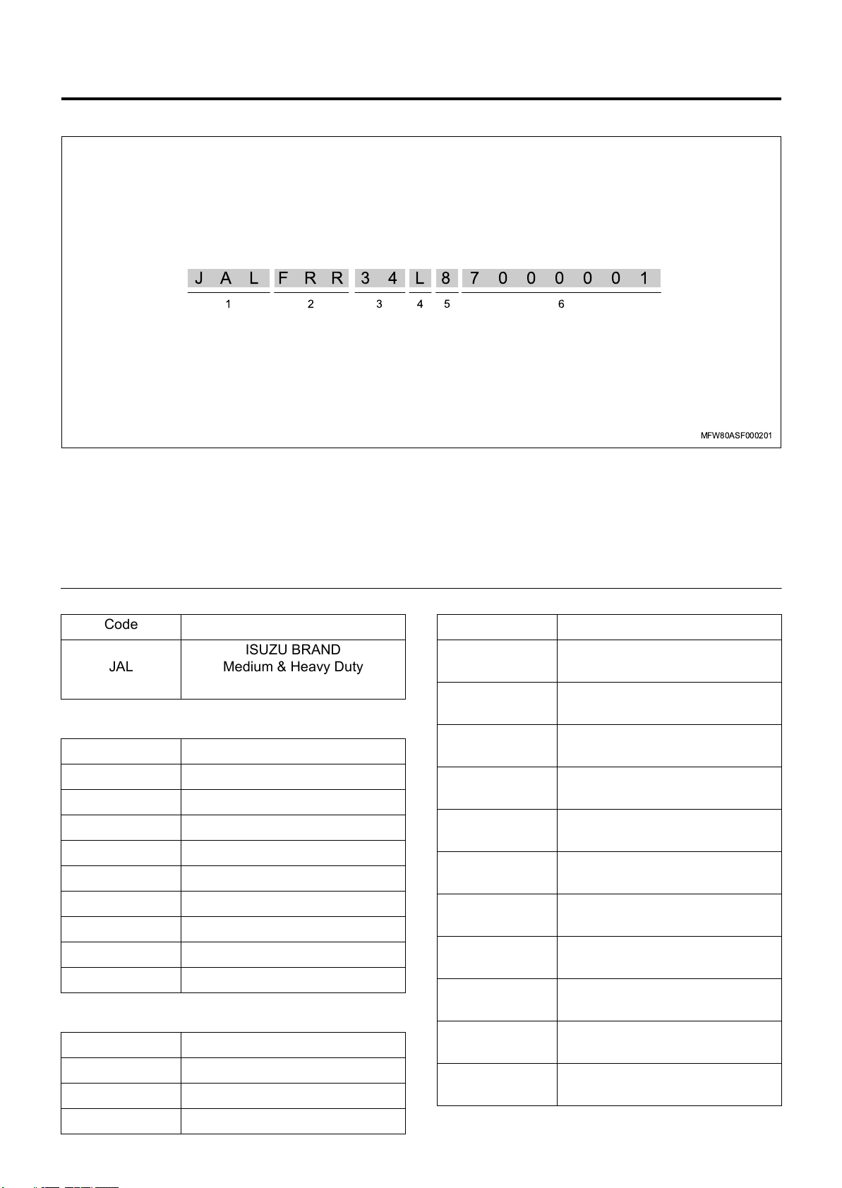
Typ e 1
JALFRR34L87000001
Legend
1. World manufacturer identifier (WMI)
2. Vehicle model code
3. Engine code
4. Wheel base code
5. Model year code
6. Chassis number
1. World manufacturer identifier (WMI)
654321
MFW80ASF000201
4. Wheel base code
Code
JAL
2. Vehicle model code
Code
FRR 4x2 Truck FRR model
FSR 4x2 Truck FSR model
FTR 4x2 Truck FTR model
FVR 4x2 Truck FVR model
FVZ 6x4 Truck FVZ model
FVM 6x2 Truck FVM model
GVR 4x2 Tractor GVR model
FSS 4x4 Truck FSS model
FTS 4x4 Truck FTS model
3. Engine code
Code
34 6HK1 Engine
86 6HF1 Engine
ISUZU BRAND
Medium & Heavy Duty
Incomplete Vehicle
Code
H
J
K
L
M
N
P
7
R
S
T
3,201 - 3,500 mm
(126.02 - 137.80 in)
3,501 - 3,800 mm
(137.83 - 149.61 in)
3,801 - 4,100 mm
(149.65 - 161.42 in)
4,101 - 4,400 mm
(161.46 - 173.23 in)
4,401 - 4,700 mm
(173.27 - 185.04 in)
4,701 - 5,000 mm
(185.08 - 196.85 in)
5,001 - 5,300 mm
(196.89 - 208.66 in)
5,301 - 5,600 mm
(208.70 - 220.47 in)
5,601 - 5,900 mm
(220.51 - 232.28 in)
5,901 - 6,200 mm
(232.32 - 244.09 in)
6,201 - 6,500 mm
(244.13 - 255.91 in)
90 4HK1 Engine
Page 16
General Information 0A-13
Typ e 2
Code
U
V
W
5. Model year code
6,501 - 6,800 mm
Code
(255.94 - 267.72 in)
6,801 - 7,100 mm
(267.76 - 279.53 in)
7,101 - 7,400 mm
(279.57 - 291.34 in)
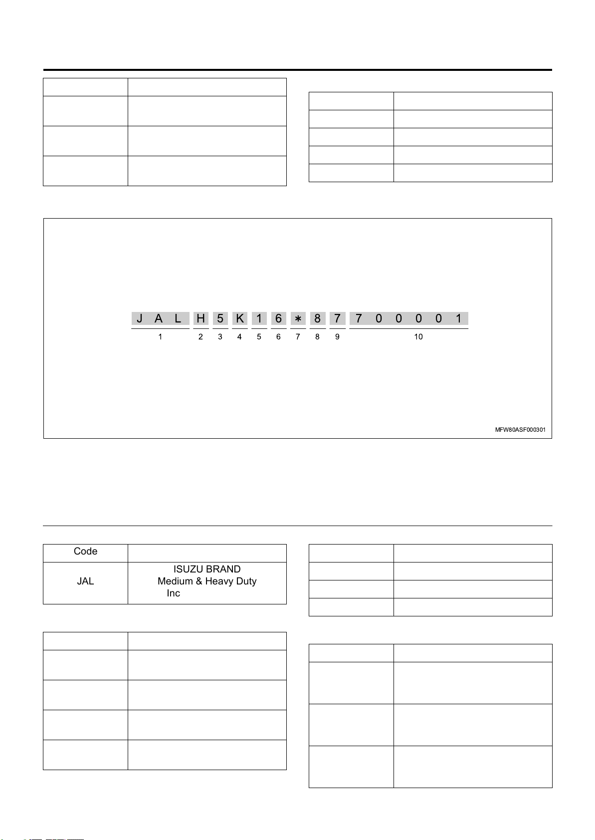
JAL 5K16 87
H
2 431
8 9765
8 2008MY
9 2009MY
A 2010MY
B 2011MY
700001
10
Legend
1. World manufacturer identifier (WMI)
2. Gross vehicle weight (GVW) and brake system
3. Series code
4. Line/Cab type code
5. Chassis code
1. World manufacturer identifier (WMI)
Code
ISUZU BRAND
JAL
Medium & Heavy Duty
Incomplete Vehicle
2. Gross vehicle weight (GVW) and brake system
Code
H
K
M
P
8,846 - 10,659 kg
(19,501 - 23,500 lb)
10,660 - 11,793 kg
(23,501 - 26,000 lb)
11,794 - 14969 kg
(26,001 - 33,000 lb)
14,970 - 18,370 kg
(33,001 - 40,500 lb)
6. Engine code
7. Check digit
8. Model year code
9. Plant code
10. Production sequential number
3. Series code
Code
5FRR
6FSR
7 FTR, FTS, FVR
4. Line/Cab type code
Code
K
M
S
BBC = 1,726 mm (67.95 in),
BBC = 2,066 mm (81.34 in),
BBC = 2,066 mm (81.34 in),
MFW80ASF000301
Tilt cab,
Narrow Cab
Tilt cab,
Narrow Cab
Tilt cab,
Wide Cab
Page 17
0A-14 General Information
5. Chassis code
Code
1 4x2, 2 Axles, 1 driving
2 4x4, 2 Axles, 1 driving
4 6x4, 3 Axles, 2 driving
6. Engine code
Code
36HK1-TC
64HK1-TC
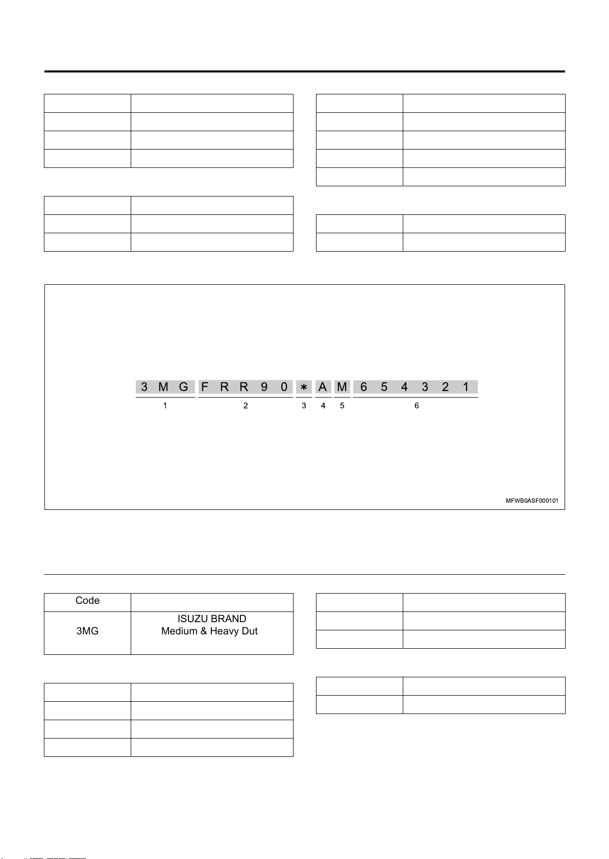
Typ e 3
8. Model year code
Code
8 2008MY
9 2009MY
A 2010MY
B 2011MY
9. Plant code
Code
7 Fujisawa
3MG FRR 9 0 AM654321
Legend
1. World manufacturer identifier (WMI)
2. General attributes
3. Check digit
1. World manufacturer identifier (WMI)
Code
ISUZU BRAND
3MG
2. General attributes
Code
FRR90 FRR90
Medium & Heavy Duty
Incomplete Vehicle
643 521
MFWB0ASF000101
4. Model year code
5. Plant code
6. Production sequential number
4. Model year code
Code
A 2010MY
B 2011MY
5. Plant code
Code
MMexico (IMEX)
FTR34 FTR34
FVR34 FVR34
Page 18

General Precautions
General Information 0A-15
General Precaution
Legend
1. Clean and safe costume
2. Installation of Chock blocks
1
2
3
MFW70AMF000201
3. Support by stand after jack up
Work preparations
• Prepare the tools, instruments, and special tools in
advance.
• Prepare the parts that require replacement and
parts that cannot be re-used in advance.
Clothing
• The service technician must wear a clean service
technician uniform, hat, and safety footwear.
Protect the vehicle.
• Make sure to use a seat cover, etc.
• Disconnect the terminal of the battery (–) in
advance.
Always focus on safety
• Make sure to use chock block when the vehicle is
jacked up.
• After jacking up, make sure to support the
specified position using a stand.
• When lifting up the vehicle using a lift, make sure
to set the safety device.
• When performing a procedure with two or more
people, make sure to ensure each other's safety
before performing an action.
• Do not leave the engine running for an extended
period of time or perform painting in a poorly
ventilated working environment.
• Make sure to use only the special tools if the
procedure requires them for the work. Performing
the procedure using other tools may cause
damage to parts or personal injury.
• Do not use tools such as a wrench that has lost its
edges, a hammer with frayed edges, or a chipped
chisel.
• When performing work using a device such as a
grinder, crane, or welder, make sure that a
qualified technician performs the procedure while
paying sufficient attention to the handling
precautions.
Page 19

0A-16 General Information
• When performing maintenance on fuel systems,
make sure that there is no fuel leakage. (may
possibly catch fire)
• When handling volatile materials, take care that
they do not catch fire.
Also make sure to wipe away any oil that sticks to
rubber parts, as it can cause deterioration.
Work Precaution
• Arrange removed parts in the correct order and
ensure they do not get mixed up with parts that
cannot be re-used.
• Perform sufficient cleaning and washing when
performing assembly / installation.
Also perform sufficient grease removal for areas to
apply liquid gasket, etc.
After-procedure check
• After completing the procedure, perform a final
check to confirm that the problem has been solved.
• Check that there is no fuel, oil, or coolant leakage.
Page 20
Lifting Instruction
General Information 0A-17
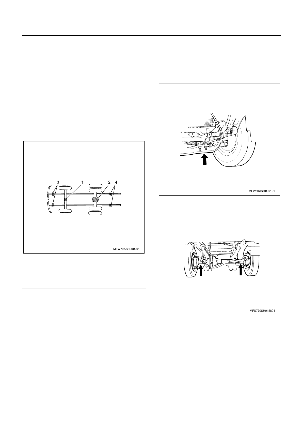
Lifting Instruction
If it necessary to use a lifting device other than the
original equipment jack, see illustration for acceptable
lifting points.
Lifting should only be done at the positions indicated to
prevent possible damage to the vehicle.
CAUTION:
Failure to observe the acceptable lift points may result
in unsatisfactory vehicle performance or a durability
failure which may result in loss of control of the vehicle.
Garage Jack and Safety Stand
Lifting Point and Supportable Point Location
31 24
Lifting Point Positions - Front side
CAUTION:
Do not lift or support on engine oil pan.
F*R/FVM/FVZ/GVR models
MFW80ASH000101
FSS model
Legend
1. Front axle
2. Rear axle center
3. Side member front side
4. Side member rear side
MFW70ASH000201
MFU770SH015801
Page 21
0A-18 General Information
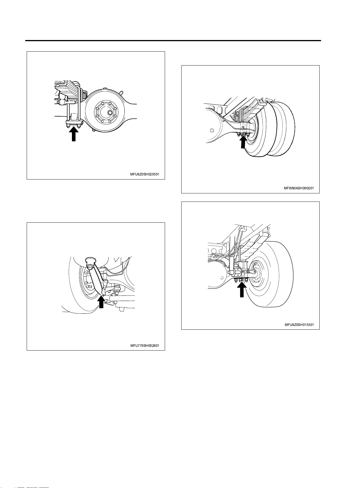
FTS model
Lifting Point Positions - Rear side
CAUTION:
Do not lift or support on rear axle tube.
FRR/FSR/FTR/FVR/GVR models (with leaf spring
suspension), FSS/FTS models (except rear singletire model)
MFU8Z0SH025501
MFW80ASH000201
FSS/FTS models (rear single-tire model)
FRR/FSR models (with air suspension)
MFU9Z0SH015301
MFU770SH002801
Page 22
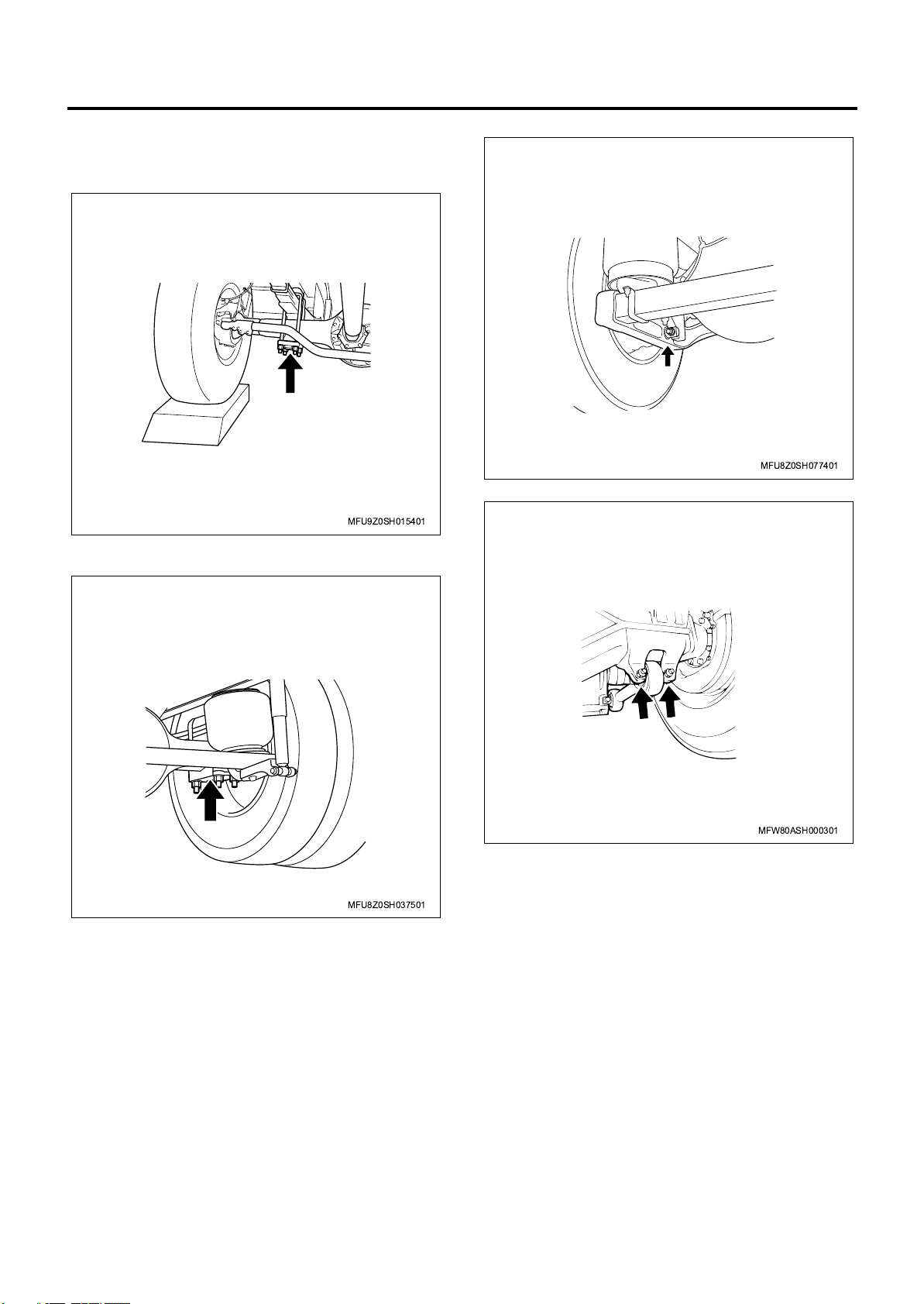
General Information 0A-19
NOTE:
Let the tire run over a piece of block, etc., and apply the
jack.
FTS model(rear single-tire model)
MFU9Z0SH015401
FVR/FVM/FVZ/GVR models (with air suspension,
except Europe)
FVR model (with air suspension, for Europe)
MFU8Z0SH077401
FVM/FVZ models (with leaf spring suspension)
MFU8Z0SH037501
MFW80ASH000301
Page 23

0A-20 General Information
Caution for The Maintenance of Electrical Parts
Battery Cable
Disconnecting the battery cables
1. Turn all the switches "OFF".
2. Disconnect the battery ground cable (1).
3. Disconnect the battery plus cable (3).
4. Disconnect the battery cable (2).
CAUTION:
Make sure to disconnect the battery ground cable first.
Disconnecting the plus cable first may cause a short
circuit.
3
1
2
MFW70ASH000401
Connecting the battery cables
Connect the battery cables in the reverse order of the
disconnection procedure.
CAUTION:
Clean the area surrounding the battery terminal, and
apply a thin layer of grease to the terminal to prevent
corrosion.
• Check that no foreign material or water has
entered the inside of the connectors.
Remove any foreign material or water that has
entered the connector using an air brush, etc. If the
material cannot be removed, replace them.
• Check that no foreign material is stuck to the
terminals, and there is no corrosion or
deformation.
Remove any foreign material by cleaning with an
air brush, or clean rag, etc. If the material cannot
be removed by cleaning, or there is corrosion or
deformation, replace them.
• Gently pull the wires to check that no terminals are
missing from the connector and there is no
breakage in the terminal area.
If a terminal is missing, reinsert it until it locks into
place. If you find a disconnection, replace them.
• Insert the male connector into the same female
connector, and check that there is no abnormality
in the terminal contact pressure.
If you find an abnormality, replace them.
• For waterproof connectors, check that there is no
damage or foreign material stuck to the seal parts
(wire seal of wiring, O-ring or waterproofing seal of
connector, etc.) or seal area of the connector
housing.
Remove any foreign material by cleaning with an
air brush, or clean rag, etc. If the material cannot
be removed by cleaning, or there is damage,
replace them.
CAUTION:
• Do not perform polishing that would remove the
plating of the terminals, nor wash the inside of the
connector. If there is dirt that requires washing,
replace them.
• Be careful when attaching the seal areas of
waterproof connectors, as some have specific
positions and directions they must be attached.
Also do not attach them in a twisted state.
Connector Handling Requirements
Visual inspection
With the male and female connectors connected
• Gently pull the connector and check whether the
connector becomes disconnected or partially
disconnected, and that the lock is properly set.
If a problem is found, reconnect the connectors.
• Check that there is no damage to the connector
housing.
If a problem is found, perform replacement.
With the male and female connectors disconnected
Regarding vehicle washing
Even for electric parts that are installed outside the cab
and are waterproofed, try to avoid exposing them
directly to high pressure water when washing the
vehicle (cover them with plastic sheets, etc.) as much
as possible.
Page 24
General Information 0A-21
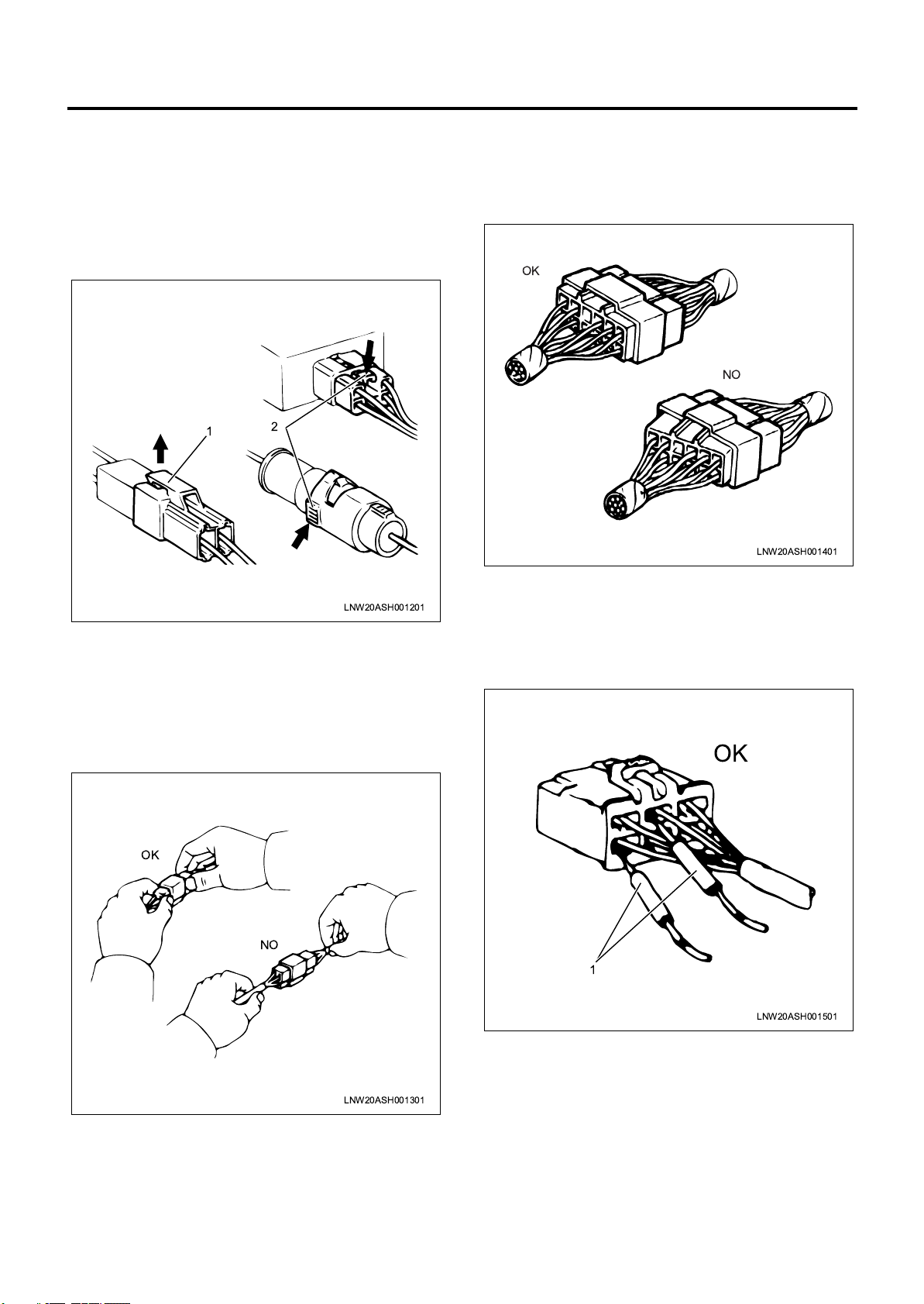
Disconnecting the connector
Many connectors have a lock to ensure secure
connections.
The two types of locks generally used are those that
open by lifting the release area of the lock (1), and
those that open by pressing the release area (2).
Before disconnecting the connector, determine in
advance which type of lock the connector is using.
1
2
Connecting the connector
Securely grasp the female side and male side of the
connector, and align them correctly.
Firmly push them together until both sides click into
place.
OK
NO
LNW20ASH001401
LNW20ASH001201
When disconnecting the connector, first securely grasp
the male side and female side of the connector.
Release the lock, and carefully disconnect the
connector.
Do not pull the harness when disconnecting the
connector, as this may cause wires to come out or
break.
OK
NO
Connector circuit inspection requirements
Check the continuity of the connector using a circuit
tester. Insert the probes (1) of the tester from the
harness side of the connector, as indicated in the
diagram.
OK
1
LNW20ASH001501
LNW20ASH001301
Page 25
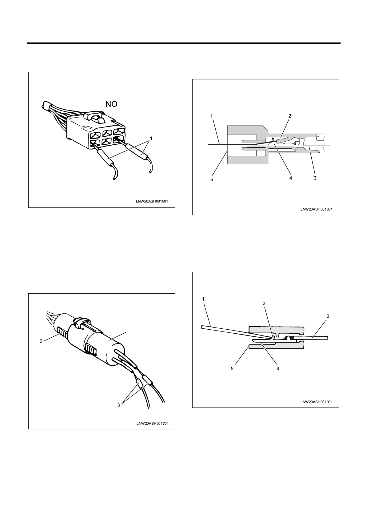
0A-22 General Information
Never insert the probes (1) from the connection closure
area of the connector, as this will cause the connector
terminals to break.
NO
1
LNW20ASH001601
Inspection requirements for waterproof connector
circuit
For waterproof connectors, the probes of the tester
cannot be inserted from the wiring side, due to the
structure of the connectors.
Therefore, perform the continuity inspection as
indicated in the diagram, by connecting a testing
connector (1) prepared in advance to the connector (2)
to test, and connect the probes (3) of the tester to the
harness of the testing connector.
2. Push the lock (2) up in the direction of the arrow
using the metal rod to release the lock. In that
state, pull out the harness (3) together with the
terminal (4).
1
5
2
4
LNW20ASH001801
3
—Terminal lock type
1. Insert a metal rod (1) from the connector closure
area (5).
2. As indicated in the diagram, release the terminal
lock (2) by pushing it to the harness side, pull out
the harness (3) together with the terminal (4).
1
2
3
LNW20ASH001701
Disconnecting connector terminals
—Built-in lock type
1. As indicated in the diagram, insert a thin
screwdriver-shaped metal rod (1) from the
connector closure area (5).
1
2
3
45
LNW20ASH001901
Connecting connector terminals
1. Check that the terminal lock (1) area is raised fully
and can be locked.
2. Insert the terminal (3) from the harness (2) side of
the connector, and push it in until the lock area
clicks.
Page 26
General Information 0A-23
3. Gently pull the harness and check whether the
terminal is completely locked inside the connector.
1
2
3
LNW20ASH002001
Replacing the fuse
WARNING:
If a fuse melts down, make sure to replace it with a nondefective fuse of the same capacity, after identifying the
cause of the melt down.
If you use a fuse with high capacity, the fuse will not
perform its function when excess current flows. This
may cause parts or wires, etc. to burn, and can result in
a vehicle fire.
Handling Electronic Parts
Handle electronic parts with sufficient care, and do not
damage the parts by dropping or throwing them.
LNW20ASH002201
Cable Harness
1. When installing electronic parts, take care to
ensure the harness does not get stuck and do not
forcibly push the harness in.
30A 60A
10
15
LNW20ASH002101
LNW20ASH002301
2. Make sure that all connections are clean and
secure.
Page 27
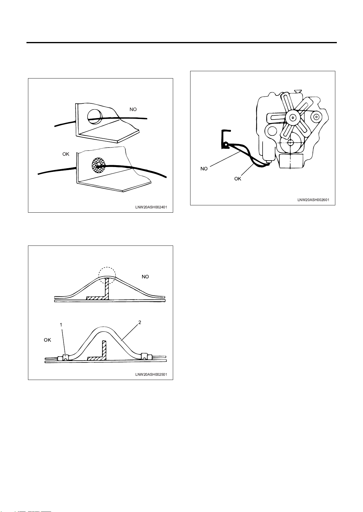
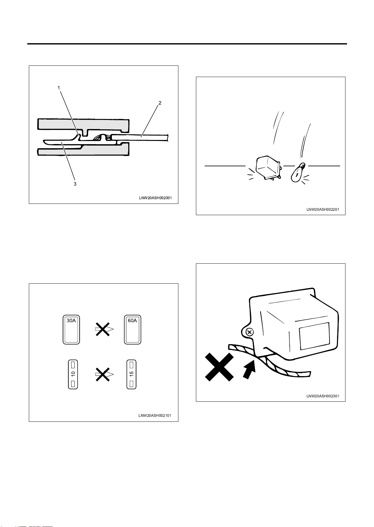
0A-24 General Information
3. When the harness will be contacting sharp edges
or surfaces of other parts, protect the harness
using a grommet or tube to prevent damage due to
the contact.
NO
OK
LNW20ASH002401
4. When wiring the harness by diverting it around
other parts, give the harness a sufficient amount of
free length, and use a protective tube (2) and clip
(1) to ensure it does not contact surrounding parts.
5. For wiring between the engine and chassis, give
the wiring sufficient free length to prevent wear and
damage caused by vibrations.
NO
OK
LNW20ASH002601
OK
NO
1
2
LNW20ASH002501
Page 28
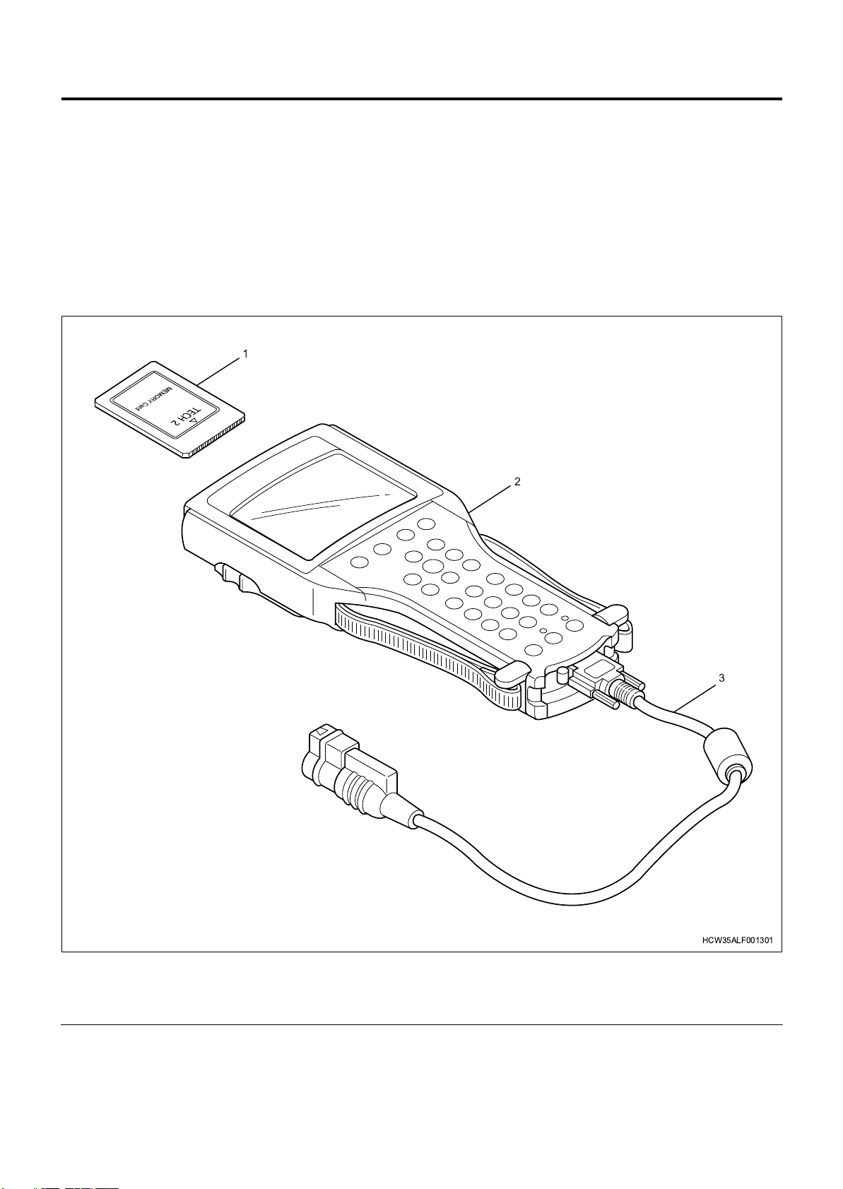
Regarding The Scan Tool
Trouble Diagnosis Using The Scan Tool
Regarding the scan tool (Tech2) / Tech2 24 volt
adaptor 2 /CAN-di module
This tool is effective for diagnosing electrical failures in
electronic control units and performing system checks.
If you connect the Tech2 to the DLC installed in the
vehicle, it performs communication with the control
units of the vehicle, and enables various diagnoses and
tests to be performed.
1
General Information 0A-25
2
Legend
1. PCMCIA card (dedicated)
2. Tech2 (body)
3
HCW35ALF001301
3. DLC cable
Page 29
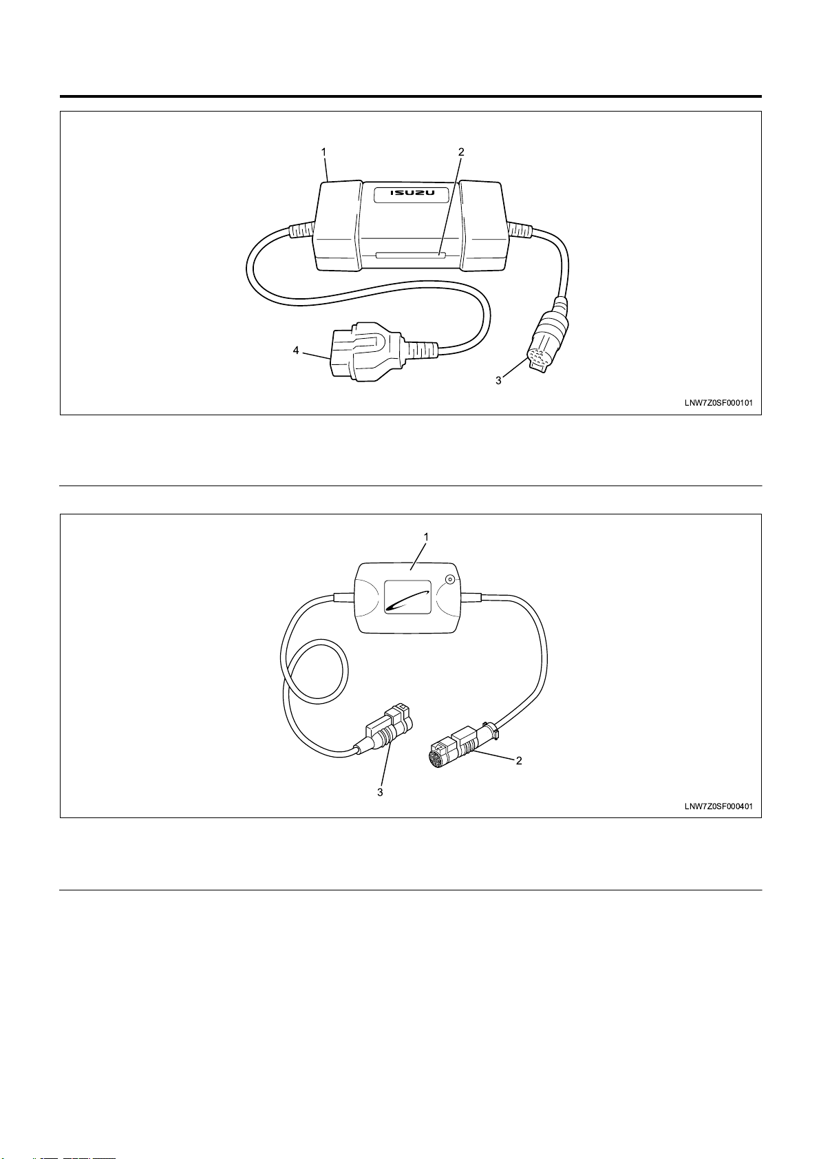
0A-26 General Information
Legend
1. Tech2 24V adaptor 2 (body)
2. Signal change switch
[Euro4 specification]
1 2
4
3
LNW7Z0SF000101
3. Tech2 connecting cable
4. DLC connecting cable
3
Legend
1. CAN-di module (body)
2. Tech2 connecting cable
Features and cautions regarding the scan tool
(Tech2) / Tech2 24 volt adaptor 2 / CAN-di module
[Euro4 specification]
• The Tech2 has a 12 V power system. Do not
directly use 24 V power. Do not directly supply
power from the cigar lighter.
• Remove/install the PCMCIA card after turning the
power off.
• The Tech2 has the capacity for two snapshots.
• As the PCMCIA card is sensitive to magnetism and
static electricity, take care when handling it.
1
2
LNW7Z0SF000401
3. DLC connecting cable
• The Tech2 is able to draw graphs of snapshots.
• To select a menu, press the selection key or
choose a menu with a function key and press the
ENTER key.
• You can return to the main menu at any time by
pressing the EXIT key.
• To clear the diagnostic trouble codes (DTC), open
the application menu and select "Clear DTC
Information".
• The Tech2 adaptor 2 has a built-in DC to DC
converter (that converts 24 V to 12 V).
Page 30
General Information 0A-27
• The Tech2 adaptor 2 has a selector for switching
signals (the signals for each electronic control unit
(ECU)).
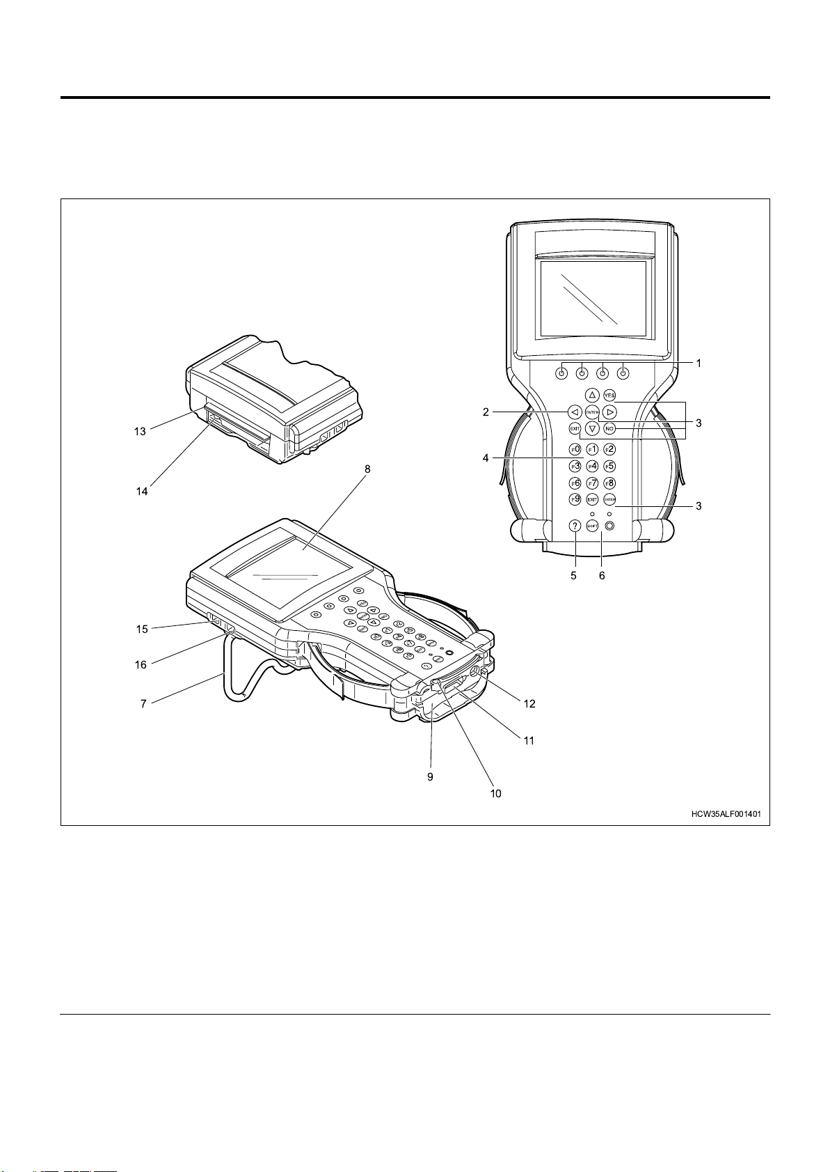
Parts of the Tech2
13
14
• The CAN-di module has a built-in signal converter
(that converts CAN serial data to keyword serial
data)
1
2
4
8
3
3
15
16
7
Legend
1. Soft key
2. Selection key (arrow key)
3. Action keys (YES, NO, ENTER, EXIT)
4. Function key (F0 – F9)
5. Help key (?)
6. Control key (PWR or SHIFT)
7. Wide stand
8. Display (liquid crystal display)
9. Vehicle communication interface (VCI) Module
1. Soft keys
When operating the Tech2, the selection box is
displayed on the top of the screen. The soft keys
correspond to that selection box. The soft keys
cannot be used unless the selection box is
56
12
11
9
10
HCW35ALF001401
10. VCI module fastening bar
11. DLC cable connecting connector
12. AC adaptor connector
13. PCMCIA card insertion opening (with cover)
14. PCMCIA card release (removal) button
15. Connector for external communication (RS-485
port)
16. Connector for external communication (RS-232
port)
displayed on the screen.
2. Selection key (arrow key)
Selects menu items on the Tech2 screen, and
switches the display. The highlighted area of the
screen display indicates what is being selected.
Page 31

0A-28 General Information
3. Action keys (YES, NO, ENTER, EXIT)
Confirm Tech2 operations, respond to screen
instructions/questions, switch/move to the various
menu screens.
4. Function keys (F0 - F9)
Confirm menu functions displayed on the screen.
Also when "F0" etc., is displayed on the menus on
the screen, the keys correspond to that display.
5. Help key (?)
Displays a screen explaining the Tech2 function
being used.
6. Control key (PWR or SHIFT)
The PWR key turns the power of the Tech2 ON/
OFF. The SHIFT key is used when adjusting the
screen contrast. The LED (orange) lights up when
the SHIFT key is available. At this time, the key
and functions other than the selection key are
locked. The LED (green) lights up when the power
is turned ON.
7. Wide stand
Used as a stand. The operating angle of the stand
is 0 to 180°.
8. Display (liquid crystal display)
The liquid crystal display has a contrast
adjustment function. Displays the ECM information
and the various instruction screens.
9. Vehicle communication interface (VCI) module
The module that enables communication between
the vehicle and Tech2.
10. VCI module fastening bar
Operate the bar to attach/fix, or remove the VCI.
11. DLC cable connecting connector
Connector for using (connecting) the Tech2 with
the vehicle. Connect the DLC cable.
12. AC adaptor connector
Connector for connecting the included AC adaptor.
Enables the Tech2 to be used away from the
vehicle.
13. PCMCIA card insertion opening (with cover)
Open the cover to insert a PCMCIA card into the
Tech2. Insert the PCMCIA card with the cover
opened. Never insert/remove the PCMCIA card
with the Tech2 turned ON.
14. PCMCIA card release (removal) button
Used when removing the PCMCIA card from the
Tech2. The PCMCIA card can be removed when
the button is pressed. Never remove the PCMCIA
card with the Tech2 turned ON.
15. Connector for external communication
(RS-485 port)
This port is for connecting to a telephone line, but
is currently not used for the Tech2. Do not connect
a telephone line, etc., to this port.
16. Connector for external communication
(RS-232 port)
This port is for connecting the Tech2 to another
computer.
Parts of the Tech2 24 V adaptor 2
2
1. Signal change switch
The Tech2 adaptor 2 has a selector for switching
signals (the signals for each electronic control unit
(ECU)).
(The position of the switch is free for other than the
following device)
•“1” : —
•“2” : HSA
1
3
LNW7Z0SF000301
• “3” : —
2. DLC connecting cable
Connects the Tech2 adaptor 2 to the vehicle DLC
(pole 16, blue).
3. Tech2 connecting cable
Connects the Tech2 adaptor 2 to the Tech2.
Page 32

Parts of the CAN-di module [Euro4 specification]
General Information 0A-29
1
1. Tech2 connecting cable
Connects the CAN-di module to the Tech2.
2. DLC connecting cable
Connects the CAN-di module to the Tech2 adaptor
2.
Connection method
1. Insert the ISUZU system PCMCIA card into the
Tech2 unit.
2. Connect the DLC cable to the Tech2 unit.
3. Connect the CAN-di module to the DLC cable.
[Euro4 specification]
4. Connect the Tech2 24 V adaptor 2 to the CAN-di
module. [Euro4 specification]
Connect the Tech2 24 V adaptor 2 to the DLC
cable. [Except Euro4 specification]
5. Confirm that the ignition is turned "OFF".
6. Connect the Tech2 24 V adaptor 2 to the vehicle
side DLC connector (pole 16, blue).
RHD model
9
1
10
2
11
3
12
4
13
5
14
6
15
7
16
8
2
LNW7Z0SF000501
LHD model
9
1
10
2
11
3
12
4
13
5
14
6
15
7
16
8
MFW82ASH000401
NOTE:
The CNG engine becomes sensitive to fluctuation of
the power voltage when the temperature of ECM unit is
high while or after driving, and communication failures
may occur.
To avoid this situation, input 12 V power supply from a
12 V battery using a battery power cable, separately
from the power for the Tech2 24 V adaptor 2.
• Do not input 24 V battery power supply to the Tech2
unit. Do not use the cigar lighter power supply on
the vehicle side, which is also 24 V.
MFA7Z0SH000201
Page 33

0A-30 General Information
1
2
3
4
5
MFW90ASH000401
Legend
1. Tech2
2. Battery power cable
3. 3 A fuse
4. Clip (black)
5. Clip (red)
• If the power supply is not input, check the 3 A fuse.
7. Turn the ignition "ON", and press the "PWR" key of
the Tech2.
8. Confirm the display of the Tech2.
Press (ENTER) To Continue
HCW46ESH001901
CAUTION:
Remove/install the PCMCIA card after confirming that
power is not being supplied to the Tech2.
Page 34

Recommended Liquid Gasket
Recommended Liquid Gasket
Type Product name Manufacturer name Area used (reference)
General Information 0A-31
ThreeBond 1207B
Silicon type
(Room temperature
vulcanization process)
ThreeBond 1207C
ThreeBond 1215
ThreeBond 1216
ThreeBond 1281
Water Base ThreeBond 1141E ThreeBond
ThreeBond 1102
Solvent
ThreeBond 1104
ThreeBond 1194
LOCTITE 515
Anaerobic
LOCTITE 518
LOCTITE 17430
FMD127
• Make sure to use a liquid gasket with the above
product name or equivalent.
• Do not use LOCTITE 515, 518 or FMD 127, as
they are anaerobic, and do not provide sufficient
effect when there is a gap larger than 0.25 mm
(0.010 in) between the contact surfaces of metals.
• Use an appropriate amount of liquid gasket. Follow
the handling precautions for the product.
ThreeBond
ThreeBond
ThreeBond
ThreeBond
ThreeBond
ThreeBond
ThreeBond
ThreeBond
LOCTITE
LOCTITE
LOCTITE
LOCTITE
Application method
1. Wipe any water or oil from the contact surface.
2. Apply liquid gasket of the specified bead width to
Engine oil seal retainer
Engine oil pan
Timing gear case
Cylinder head cover
Fuel pump
Water pump
Rear axle
Etc.
Engine oil seal retainer
Water pump
Transaxle
Etc.
Make sure the contact surface is dry.
one side of the contact surface. Make sure there
are no cuts in the beads.
1.Completely remove lubricant and moisture from the connecting surfaces.
The surfaces must be perfectly dry.
2.Apply specified bead width of liquid gasket to one of the connecting surfaces.
There must be no gaps in the bead.
mm (in)
SCREW
HOLE
13
(0.040.12)
13
(0.040.12)
DEPRESSION
More than
2 (0.08)
JUDGE
MENT
OK
OK
NG
Depression
Apply liquid gasket to
the bolt hole interior
Example
Anaerobic Type:2-3 mm (0.08-0.12 in)
Others :2-6 mm (0.08-0.24 in)
Specified
bead width
MFW70AMF000101
Page 35

0A-32 General Information
NOTE:
If the repair manual specifies an application method,
follow that method.
Page 36

Recommended Thread Locking Agent
Recommended Thread Locking Agent
Type Color
LOCTITE 242 Blue
LOCTITE 262 Red
LOCTITE 271 Red
Work procedure
1. Completely wipe off any water or oil from the
contact surface of the bolt and bolt hole, and the
threaded portion of nut. Make sure the contact
surface is dry.
2. Apply LOCTITE to the end 1/3 of the screw.
General Information 0A-33
LNW20ASH003201
3. Tighten the bolt at the specified torque.
CAUTION:
After tightening, do not apply excessive torque or
vibrations for at least an hour until the Loctite hardens.
Page 37

0A-34 General Information
Maintenance Schedule
Introduction
When performing the checks on the following items,
regular inspection items should also be checked.
Abbreviations Used in This Manual
I : Inspect, clean, or repair or replace as required
A : Adjust
R : Replace
T : Tighten to the specified torque
L : Add lubricant
Page 38

Maintenance Schedule (for Euro4 specification except Europe)
for Euro4 specification except Europe (1/6)
Odometer reading or months,
whichever comes first
or every 15 months
or after 6th cleaning : R
Every 6 months : I
or every 3 months : I
every 6 months : R
or every 6 months
General Information 0A-35
or every 3 months : I
every 15 months : R
x1,000 miles 0.6 3 5 6 9 12 15 18 21 24 27 31 34 37 40 43 46 49 52 55 59 62 65
- - - I - I - I - I - I - I - I - I - I - I - or every 3 months
- - - I - I - I - I - I - I - I - I - I - I - or every 3 months
-----------R---------R-
T----------T---------T-orevery 15 months
A----------A---------A-orevery 15 months
-----------I---------I-orevery 15 months
- - - I - I - I - I - I - I - I - I - I - I - or every 3 months
R-- I-R- I-R- I-R- I-R-I-R-
- - - - - R - - - R - - - R - - - R - - - R - or every 6 months
- - - - - R - - - R - - - R - - - R - - - R - or every 6 months
-----R---R---R---R---R-
-----R---R---R---R---R-
Every 12 months : R
-------R-----R-----R---orevery 9 months
- - - I - I - I - I - I - I - I - I - I - I - or every 3 months
- - - I - I - I - I - I - I - I - I - I - I - or every 3 months
-----------I---------I-orevery 15 months
-----------I---------I-orevery 15 months
-----------I---------I-orevery 15 months
I - - I - I - I - I - I - I - I - I - I - I - or every 3 months
- - - I - I - I - I - I - I - I - I - I - I - or every 3 months
I - - I - I - I - I - I - I - I - I - I - I - or every 3 months
Every 24 months : I
Every 24 months : R (When Isuzu recommended coolant is used)
- - - I - I - I - I - I - I - I - I - I - I - or every 3 months
--- I- I- I- I-R-I- I- I- I-R-
- - - I - I - I - I - I - I - I - I - I - I - or every 3 months
- - - I - I - I - I - I - I - I - I - I - I - or every 3 months
Every 48 months : R
- - - I - I - I - I - I - I - I - I - I - I - or every 3 months
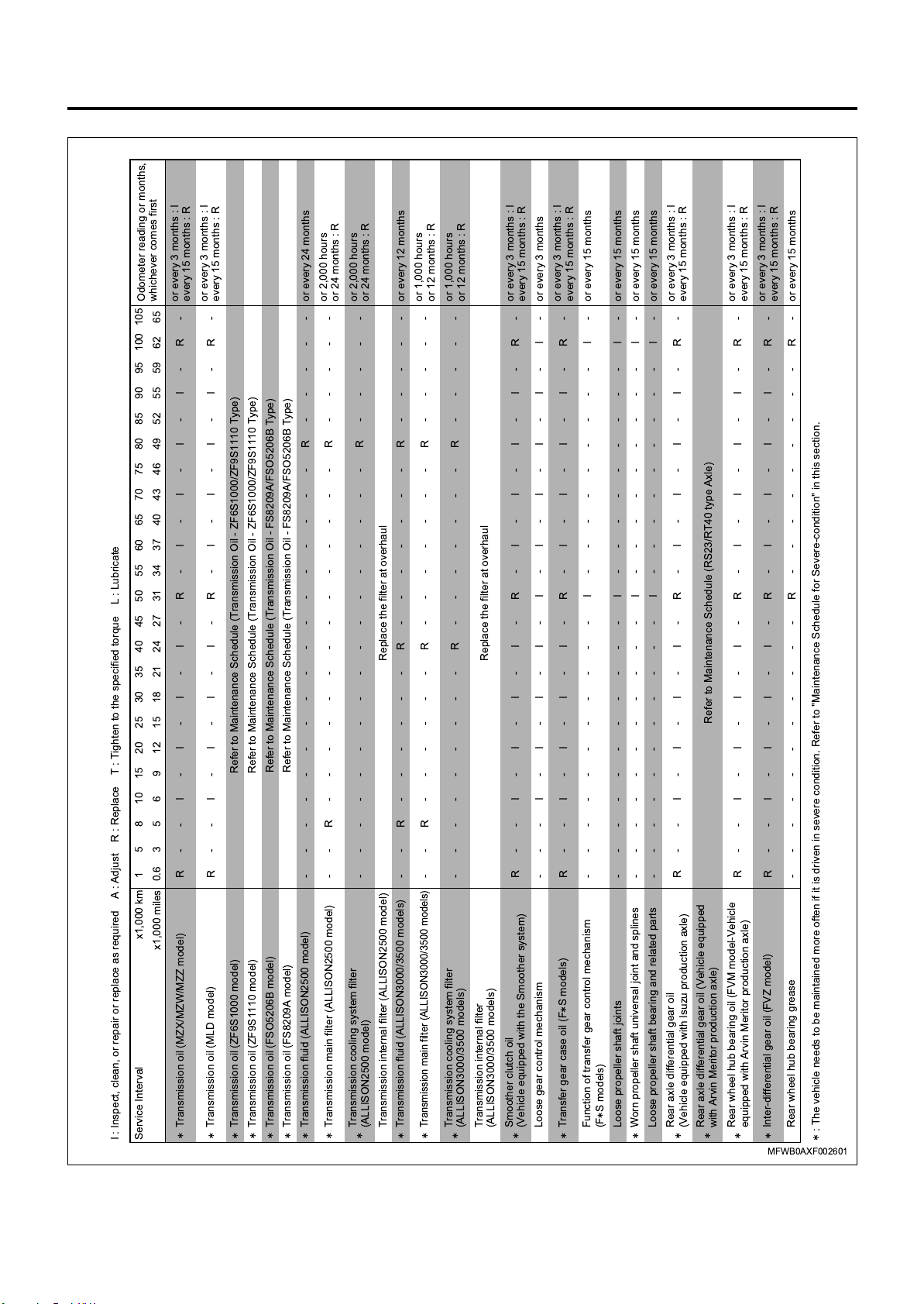
I : Inspect, clean, or repair or replace as required A : Adjust R : Replace T : Tighten to the specified torque L : Lubricate
Service Interval x1,000 km 1 5 8 10 15 20 25 30 35 40 45 50 55 60 65 70 75 80 85 90 95 100 105
Engine startability and abnormal noise
Idling speed and acceleration
Air cleaner element
Valve clearance
Intake and exhaust manifolds
Compression pressure for each cylinder
Oil contamination
Fuel injection timing
Air compressor, governor and unloader valve
functions
Radiator cap or radiator sub-tank cap function
Damage to fan belt
Loose or otherwise improper installation of
exhaust pipe
Engine oil (main and partial) filter (combined type)
Engine oil main filter (separate type)
Engine oil partial filter (separate type)
Engine oil separator (6HK1 engine model)
Engine oil
Engine oil separator (4HK1 engine model)
Fuel filter
Fuel tank strainer
Inside fuel tank
Fuel injection pressure and spray pattern
Cooling circuit and radiator
Engine coolant
Turbocharger to air duct connection and gasket
Clutch fluid (manual transmission)
Clutch pedal free play and stroke
(manual transmission)
Clutch system function (manual transmission)
Clutch booster exhaust cover (manual transmission)
Rubber parts and gaskets of clutch booster
(manual transmission)
: The vehicle needs to be maintained more often if it is driven in severe condition. Refer to "Maintenance Schedule for Severe-condition" in this section.
MFWB0AXF002001
Page 39
0A-36 General Information
for Euro4 specification except Europe (2/6)
or 2,000 hours
or 24 months : R
or 2,000 hours
Odometer reading or months,
whichever comes first
or every 3 months : I
every 15 months : R
or every 3 months : I
every 15 months : R
or 24 months : R
or 1,000 hours
or 12 months : R
or 1,000 hours
or 12 months : R
or every 3 months : I
or every 3 months : I
every 15 months : R
or every 3 months : I
every 15 months : R
every 15 months : R
or every 3 months : I
every 15 months : R
or every 3 months : I
every 15 months : R
Replace the filter at overhaul
Refer to Maintenance Schedule (Transmission Oil - FS8209A/FSO5206B Type)
Refer to Maintenance Schedule (Transmission Oil - ZF6S1000/ZF9S1110 Type)
Refer to Maintenance Schedule (Transmission Oil - FS8209A/FSO5206B Type)
-----------------R-----orevery 24 months
--R--------------R-----
-----------------R-----
--R------R-------R-----orevery 12 months
--R------R-------R-----
Refer to Maintenance Schedule (Transmission Oil - ZF6S1000/ZF9S1110 Type)
R--I-I-I-I-R-I-I-I-I-R-
R--I-I-I-I-R-I-I-I-I-R-
x1,000 miles 0.6 3 5 6 9 12 15 18 21 24 27 31 34 37 40 43 46 49 52 55 59 62 65
Replace the filter at overhaul
---------R-------R-----
R--I-I-I-I-R-I-I-I-I-R-
- - - I - I - I - I - I - I - I - I - I - I - or every 3 months
R--I-I-I-I-R-I-I-I-I-R-
-----------I---------I-orevery 15 months
-----------I---------I-orevery 15 months
-----------I---------I-orevery 15 months
-----------I---------I-orevery 15 months
R--I-I-I-I-R-I-I-I-I-R-
Refer to Maintenance Schedule (RS23/RT40 type Axle)
R--I-I-I-I-R-I-I-I-I-R-
R--I-I-I-I-R-I-I-I-I-R-
-----------R---------R-orevery 15 months
I : Inspect, clean, or repair or replace as required A : Adjust R : Replace T : Tighten to the specified torque L : Lubricate
Service Interval x1,000 km 1 5 8 10 15 20 25 30 35 40 45 50 55 60 65 70 75 80 85 90 95 100 105
Transmission oil (MZX/MZW/MZZ model)
Transmission oil (MLD model)
Transmission oil (ZF9S1110 model)
Transmission oil (ZF6S1000 model)
Transmission oil (FSO5206B model)
Transmission oil (FS8209A model)
Transmission fluid (ALLISON2500 model)
Transmission main filter (ALLISON2500 model)
Transmission cooling system filter
(ALLISON2500 model)
Transmission internal filter (ALLISON2500 model)
Transmission main filter (ALLISON3000/3500 models)
Transmission fluid (ALLISON3000/3500 models)
Transmission cooling system filter
(ALLISON3000/3500 models)
Transmission internal filter
(ALLISON3000/3500 models)
Smoother clutch oil
(Vehicle equipped with the Smoother system)
Loose gear control mechanism
Transfer gear case oil (F S models)
Function of transfer gear control mechanism
Loose propeller shaft joints
(F S models)
Worn propeller shaft universal joint and splines
Loose propeller shaft bearing and related parts
Rear axle differential gear oil
(Vehicle equipped with Isuzu production axle)
Rear axle differential gear oil (Vehicle equipped
with Arvin Meritor production axle)
Rear wheel hub bearing oil (FVM model-Vehicle
equipped with Arvin Meritor production axle)
Inter-differential gear oil (FVZ model)
MFWB0AXF002601
Rear wheel hub bearing grease
: The vehicle needs to be maintained more often if it is driven in severe condition. Refer to "Maintenance Schedule for Severe-condition" in this section.
Page 40

for Euro4 specification except Europe (3/6)
or every 3 months : I
every 15 months : R
or every 3 months : I
Odometer reading or months,
whichever comes first
every 15 months : R
General Information 0A-37
or every 3 months : I
every 15 months : R
I : Inspect, clean, or repair or replace as required A : Adjust R : Replace T : Tighten to the specified torque L : Lubricate
Service Interval x1,000 km 1 5 8 10 15 20 25 30 35 40 45 50 55 60 65 70 75 80 85 90 95 100 105
x1,000 miles 0.6 3569121518212427313437404346495255596265
-----------I---------I-orevery 15 months
Damaged or distorted rear axle case
-----------R---------R-orevery 15 months
R--I-I-I-I-R-I-I-I-I-R-
Front wheel hub bearing grease
Front axle differential gear oil (F S models)
R--I-I-I-I-R-I-I-I-I-R-
Front wheel hub bearing oil
)
Vehicle equipped with Arvin Meritor production axle
(
-----------I---------I-orevery 15 months
T----------T---------T-orevery 15 months
Damaged or distorted front axle case
Leaf spring U-bolt nuts
T----------T---------T-orevery 15 months
Air suspension's beam bolt nuts/U-bolt nuts
(Air suspension model)
- - - I - I - I - I - I - I - I - I - I - I - or every 3 months
-----------I---------I-orevery 15 months
Damaged leaf spring
Uneven suspension due to leaf spring fatigue
-------I-----I-----I---orevery 9 months
-------I-----I-----I---orevery 9 months
Loose or damaged leaf spring mounting
Spring leaves for misalignment
-------I-----I-----I---orevery 9 months
-------I-----I-----I---orevery 9 months
Oil leaks from or damage to shock absorbers
Loose shock absorber mounting
Loose or damaged air suspension main support
-----------I---------I-orevery 15 months
members (Air suspension model)
- - - I - I - I - I - I - I - I - I - I - I - or every 3 months
- - - I - I - I - I - I - I - I - I - I - I - or every 3 months
Air leaks from air suspension (Air suspension model)
Damaged air spring (Air suspension model)
- - - I - I - I - I - I - I - I - I - I - I - or every 3 months
-----------I---------I-orevery 15 months
Loose or damaged air suspension mounting
(Air suspension model)
Air spring height (Air suspension model)
-----------I---------I-orevery 15 months
Function of height sensor or leveling valve
(Air suspension model)
-----------I---------I-orevery 15 months
-----------I---------I-orevery 15 months
- - - - - I - - - I - - - I - - - I - - - I - or every 6 months
Loose or damaged torque rod (if so equipped)
Loose or damaged traverse rod (if so equipped)
Loose or damaged V-rod (if so equipped)
- - - I - I - I - I - I - I - I - I - I - I - or every 3 months
T - - T - T - T - T - T - T - T - T - T - T - or every 3 months
Wheel nuts
Foreign object in wheels
- - - I - I - I - I - I - I - I - I - I - I - or every 3 months
-----------I---------I-orevery 15 months
Damaged disc wheels
Loose front wheel hub bearings
-----------I---------I-orevery 15 months
--- I- I- I- I-R-I- I- I- I-R-
Loose rear wheel hub bearings
Power steering fluid
MFWB0AXF005001
: The vehicle needs to be maintained more often if it is driven in severe condition. Refer to "Maintenance Schedule for Severe-condition" in this section.
Page 41

0A-38 General Information
for Euro4 specification except Europe (4/6)
Odometer reading or months,
whichever comes first
or every 3 months
or every 3 months : I
every 12 months : R
or every 3 months
or every 3 months : I
every 24 months : R
x1,000 miles 0.6 3 5 6 9 12 15 18 21 24 27 31 34 37 40 43 46 49 52 55 59 62 65
-----------I---------I-orevery 15 months
--- I- I- I- I- I- I- I- I- I- I-
-----------I---------I-orevery 15 months
-- I- I- I- I- I- I- I- I- I- I-
I or every 3 months
-----------I---------I-orevery 15 months
-----------I---------I-orevery 15 months
-----------I---------I-orevery 15 months
- - - - - - - - - - - I - - - - - - - - - I - or every 15 months
---I-I-I-I-R-I-I-I-I-R-
- - - - - - - - - - - I - - - - - - - - - I - or every 12 months
--- I- I- I- I- I- I- I- I- I- I-
---I-I-I-I-R-I-I-I-I-R-
- - - - - - - - - - - I - - - - - - - - - I - or every 12 months
- - - I - I - I - I - I - I - I - I - I - I - or every 12 months
- - - I - I - I - I - I - I - I - I - I - I - or every 3 months
- - - - - - - - - - - I - - - - - - - - - I - or every 15 months
- I - I - I - I - I - I - I - I - I - I - I - or every 3 months
- - - - - - - - - - - I - - - - - - - - - I - or every 12 months
- - - - - - - - - - - I - - - - - - - - - I - or every 12 months
Change the desiccant, filter and rubber parts of air dryer
Every 24 months : RABS modulator (Vehicle equipped with ABS)
at 100,000 km (62,000 miles) or every 12 months.
Every 12 months : RRubber parts of wheel cylinder
Every 24 months : R
Every 3 months : I
Every 24 months : R
Every 24 months : R
I : Inspect, clean, or repair or replace as required A : Adjust R : Replace T : Tighten to the specified torque L : Lubricate
Service Interval x1,000 km 1 5 8 10 15 20 25 30 35 40 45 50 55 60 65 70 75 80 85 90 95 100 105
Power steering fluid filter
Excessive play in power steering bearing
Loose power steering system mounting
Damage to, loose or excessive play in power
steering joints
Knuckle-to-front axle clearance
Wheel alignment
Steering angle range for right and left turns
King pin-to-bearing clearance
Brake fluid (Vehicle equipped with the air-over
hydraulic brake system)
Brake lining wear
Brake drum wear or damage
Brake hose
Function of brake valves (Vehicle equipped with
the air-over hydraulic brake system)
Brake booster exhaust cover (Vehicle equipped
with the air-over hydraulic brake system)
Leaks from, damage to, or loose connection of
brake hose or pipe
Excessively worn cams and wheel brakes (Vehicle
equipped with Arvin Meritor production axle)
Brake chamber rod stroke (Vehicle equipped with
the full-air brake system)
Function of brake chamber (Vehicle equipped with
the full-air brake system)
Functions of brake and relay valves (Vehicle
equipped with the full-air brake system)
Air dryer
Rubber parts of HSA valve
(Vehicle equipped with HSA)
Rubber parts of brake valve, relay valve, parking
brake valve, quick release valve, reducing valve,
double check valve, multi-protection valve, AIR
MASTER, TCV, LSPV
Rubber parts of brake chamber
: The vehicle needs to be maintained more often if it is driven in severe condition. Refer to "Maintenance Schedule for Severe-condition" in this section.
MFWB0AXF001901
Page 42
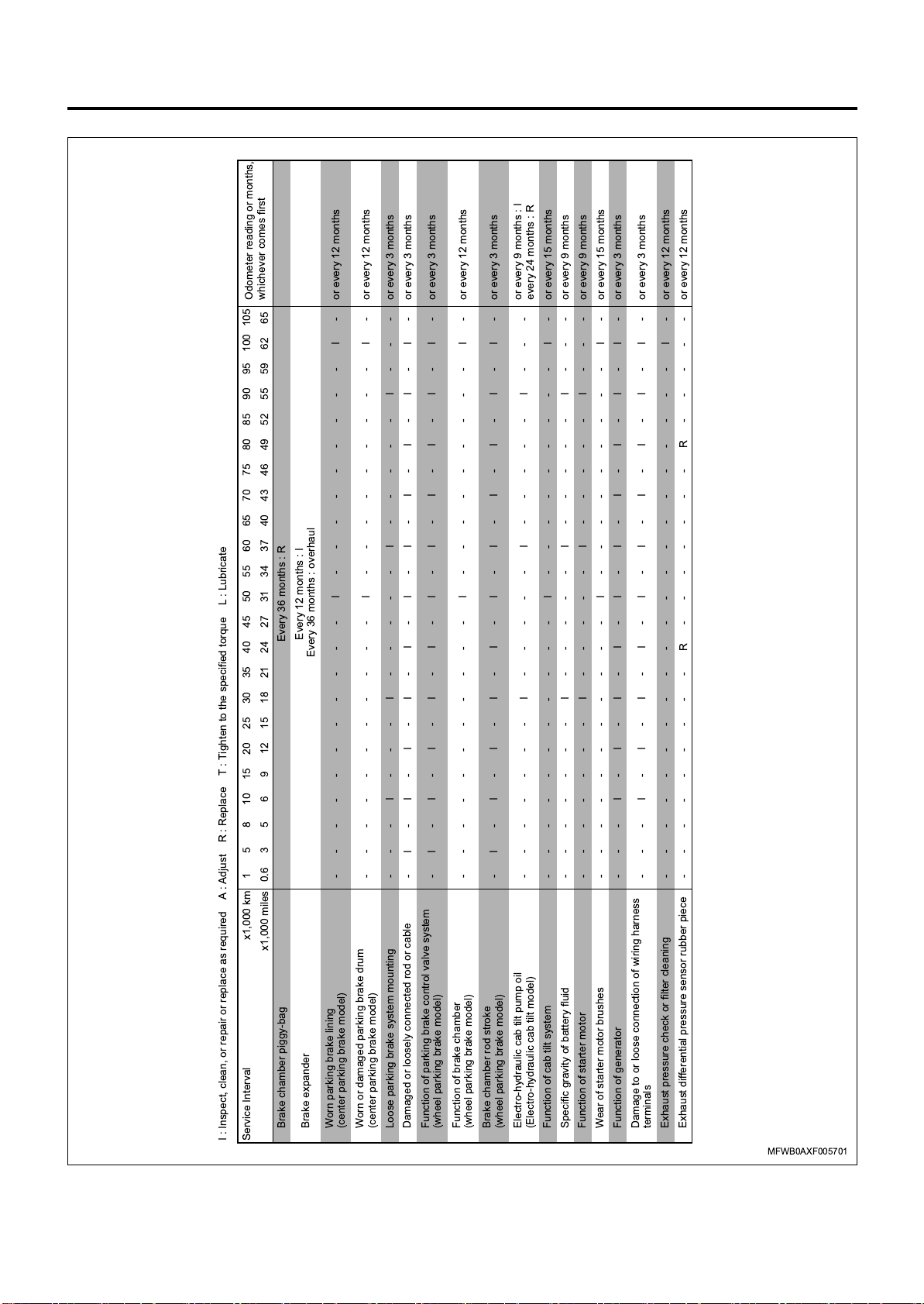
for Euro4 specification except Europe (5/6)
Odometer reading or months,
whichever comes first
General Information 0A-39
or every 9 months : I
every 24 months : R
Every 12 months : I
Every 36 months : R
Every 36 months : overhaul
-----------I---------I-orevery 15 months
- - - I - I - I - I - I - I - I - I - I - I - or every 3 months
- - - I - I - I - I - I - I - I - I - I - I - or every 3 months
-----------I---------I-orevery 12 months
-----------I---------I-orevery 12 months
- - - I - - - I - - - - - I - - - - - I - - - or every 3 months
- I - I - I - I - I - I - I - I - I - I - I - or every 3 months
- I - I - I - I - I - I - I - I - I - I - I - or every 3 months
-----------I---------I-orevery 12 months
- I - I - I - I - I - I - I - I - I - I - I - or every 3 months
-------I-----I-----I---
-----------I---------I-orevery 15 months
-------I-----I-----I---orevery 9 months
-------I-----I-----I---orevery 9 months
x1,000 miles 0.6 3 5 6 9 12 15 18 21 24 27 31 34 37 40 43 46 49 52 55 59 62 65
---------R-------R-----orevery 12 months
---------------------I-orevery 12 months
I : Inspect, clean, or repair or replace as required A : Adjust R : Replace T : Tighten to the specified torque L : Lubricate
Service Interval x1,000 km 1 5 8 10 15 20 25 30 35 40 45 50 55 60 65 70 75 80 85 90 95 100 105
Brake chamber piggy-bag
Brake expander
Worn parking brake lining
(center parking brake model)
Worn or damaged parking brake drum
Loose parking brake system mounting
(center parking brake model)
Damaged or loosely connected rod or cable
Function of parking brake control valve system
(wheel parking brake model)
Function of brake chamber
(wheel parking brake model)
Brake chamber rod stroke
(wheel parking brake model)
Electro-hydraulic cab tilt pump oil
Function of cab tilt system
(Electro-hydraulic cab tilt model)
Specific gravity of battery fluid
Function of starter motor
Wear of starter motor brushes
Function of generator
Damage to or loose connection of wiring harness
terminals
Exhaust pressure check or filter cleaning
Exhaust differential pressure sensor rubber piece
MFWB0AXF005701
Page 43

0A-40 General Information
for Euro4 specification except Europe (6/6)
Odometer reading or months,
whichever comes first
I : Inspect, clean, or repair or replace as required A : Adjust R : Replace T : Tighten to the specified torque L : Lubricate
Service Interval x1,000 km 1 5 8 10 15 20 25 30 35 40 45 50 55 60 65 70 75 80 85 90 95 100 105
x1,000 miles 0.6 3 5 6 9 12 15 18 21 24 27 31 34 37 40 43 46 49 52 55 59 62 65
------L----L----L----L-orevery 6 months
- L- LLLLLLLLLLLLLLLLLLLLorevery month
Engine water pump bearing (6HK1 engine model)
Front spring pins
- L- LLLLLLLLLLLLLLLLLLLLorevery month
- L- LLLLLLLLLLLLLLLLLLLLorevery month
Front spring shackles
King pin
(Vehicle equipped with Isuzu production axle)
King pin
Every 80,000 km (50,000 miles) or every 12 months: L
(Vehicle equipped with Arvin Merltor production axle)
Every 80,000 km (50,000 miles) or every 12 months: L
------L----L----L----L-orevery 6 months
Tie rod ends (FTR/FVR/FVM/FVZ models-Vehicle
equipped with Isuzu production axle)
Tie rod ends
(Vehicle equipped with Arvin Merltor production axle)
- L- LLLLLLLLLLLLLLLLLLLLorevery month
------L----L----L----L-orevery 6 months
Shimmy damper (F S models)
Drag link (maintenace type)
- L- LLLLLLLLLLLLLLLLLLLLorevery month
- L - L L L L L L L L L L L L L L L L L L L L or every month
Transfer input flange (F S models)
Propeller shaft universal joints and sliding sleeves
- L - L L L L L L L L L L L L L L L L L L L L or every month
- L- LLLLLLLLLLLLLLLLLLLLorevery month
Propeller shaft center bearing
Rear spring pins
- L- LLLLLLLLLLLLLLLLLLLLorevery month
Rear spring shackle pins or rear spring sliding
shackles
- L- LLLLLLLLLLLLLLLLLLLLorevery month
Trunnion shaft
(FVM/FVZ models, with leaf spring suspension)
Rear spring pads
- L- LLLLLLLLLLLLLLLLLLLLorevery month
- L- LLLLLLLLLLLLLLLLLLLLorevery month
)
Vehicle equipped with Arvin Meritor production axle
(FVM/FVZ models, with leaf spring suspension)
Front wheel brake cam shaft and slack adjuster
(
- L- LLLLLLLLLLLLLLLLLLLLorevery month
)
Vehicle equipped with Arvin Meritor production axle
Rear wheel brake cam shaft and slack adjuster
(
- L- LLLLLLLLLLLLLLLLLLLLorevery month
Steering shaft sliding sleeve
Clutch shift block
- L- LLLLLLLLLLLLLLLLLLLLorevery month
- L- LLLLLLLLLLLLLLLLLLLLorevery month
Clutch booster joint pin
(except ZF6S1000 transmission)
(FSO5206B/ZF9S1110/MLD transmission)
- L- LLLLLLLLLLLLLLLLLLLLorevery month
Cab mounting (if so equipped)
MFWB0AXF002701
Page 44
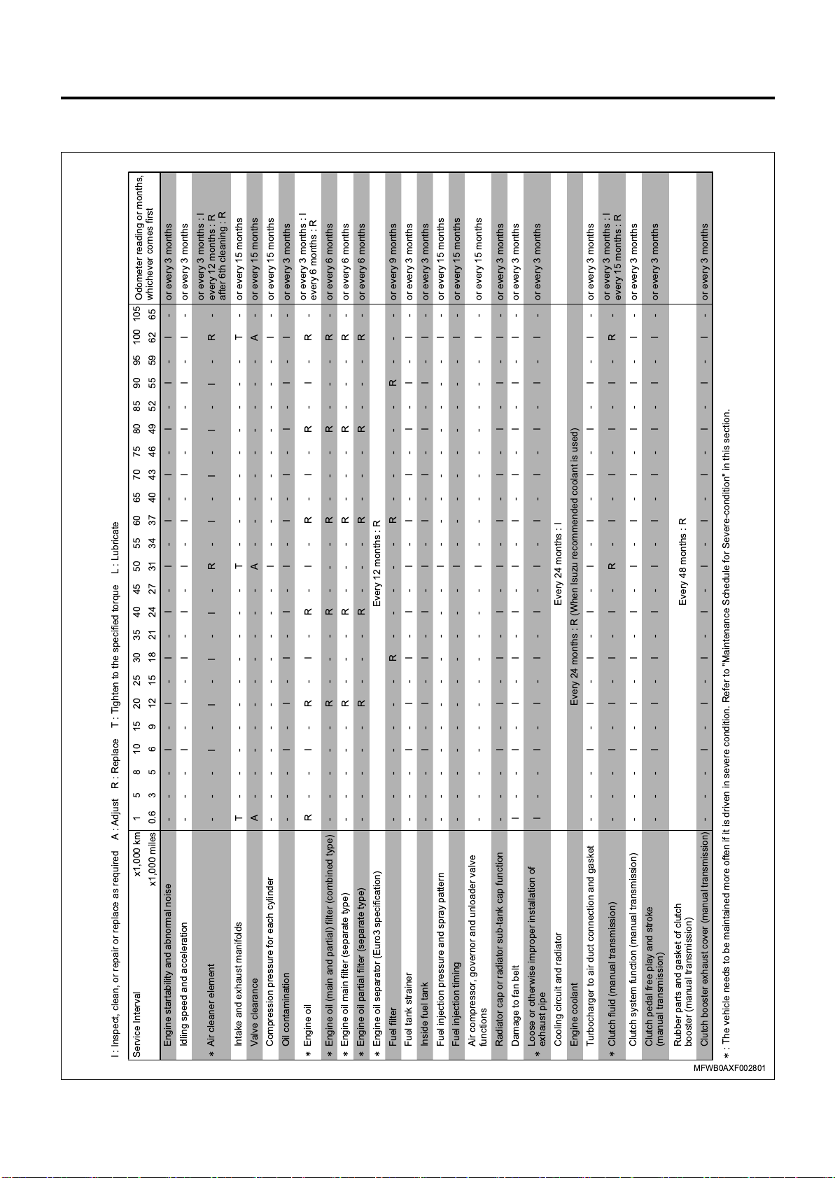
Maintenance Schedule (for Euro2, Euro3 specification)
for Euro2, Euro3 specification (1/4)
Odometer reading or months,
whichever comes first
or every 3 months : I
every 12 months : R
after 6th cleaning : R
or every 3 months : I
every 6 months : R
General Information 0A-41
or every 3 months : I
every 15 months : R
x1,000 miles 0.6 3569121518212427313437404346495255596265
- - - I - I - I - I - I - I - I - I - I - I - or every 3 months
- - - I - I - I - I - I - I - I - I - I - I - or every 3 months
---I-I-I-I-R-I-I-I-I-R-
T----------T---------T-orevery 15 months
A----------A---------A-orevery 15 months
-----------I---------I-orevery 15 months
- - - I - I - I - I - I - I - I - I - I - I - or every 3 months
R-- I-R- I-R- I-R- I-R-I-R-
-----R---R---R---R---R-orevery 6 months
-----R---R---R---R---R-orevery 6 months
Every 12 months : R
-----R---R---R---R---R-orevery 6 months
-------R-----R-----R---orevery 9 months
- - - I - I - I - I - I - I - I - I - I - I - or every 3 months
- - - I - I - I - I - I - I - I - I - I - I - or every 3 months
-----------I---------I-orevery 15 months
-----------I---------I-orevery 15 months
-----------I---------I-orevery 15 months
I - - I - I - I - I - I - I - I - I - I - I - or every 3 months
- - - I - I - I - I - I - I - I - I - I - I - or every 3 months
I - - I - I - I - I - I - I - I - I - I - I - or every 3 months
Every 24 months : I
Every 24 months : R (When Isuzu recommended coolant is used)
- - - I - I - I - I - I - I - I - I - I - I - or every 3 months
--- I- I- I- I-R-I- I- I- I-R-
- - - I - I - I - I - I - I - I - I - I - I - or every 3 months
- - - I - I - I - I - I - I - I - I - I - I - or every 3 months
Every 48 months : R
- - - I - I - I - I - I - I - I - I - I - I - or every 3 months
I : Inspect, clean, or repair or replace as required A : Adjust R : Replace T : Tighten to the specified torque L : Lubricate
Service Interval x1,000 km 1 5 8 10 15 20 25 30 35 40 45 50 55 60 65 70 75 80 85 90 95 100 105
Engine startability and abnormal noise
Idling speed and acceleration
Air cleaner element
Valve clearance
Intake and exhaust manifolds
Compression pressure for each cylinder
Oil contamination
Fuel injection timing
Air compressor, governor and unloader valve
functions
Radiator cap or radiator sub-tank cap function
Damage to fan belt
Loose or otherwise improper installation of
exhaust pipe
Engine oil (main and partial) filter (combined type)
Engine oil main filter (separate type)
Engine oil partial filter (separate type)
Engine oil
Engine oil separator (Euro3 specification)
Fuel filter
Fuel tank strainer
Inside fuel tank
Fuel injection pressure and spray pattern
Cooling circuit and radiator
Engine coolant
Turbocharger to air duct connection and gasket
Clutch fluid (manual transmission)
Clutch pedal free play and stroke
(manual transmission)
Clutch system function (manual transmission)
Clutch booster exhaust cover (manual transmission)
Rubber parts and gasket of clutch
booster (manual transmission)
: The vehicle needs to be maintained more often if it is driven in severe condition. Refer to "Maintenance Schedule for Severe-condition" in this section.
MFWB0AXF002801
Page 45

0A-42 General Information
for Euro2, Euro3 specification (2/4)
or every 3 months : I
every 15 months : R
or every 3 months : I
Odometer reading or months,
whichever comes first
every 15 months : R
or every 3 months : I
or every 3 months : I
or every 3 months : I
or every 3 months : I
every 15 months : R
every 15 months : R
or every 3 months : I
every 15 months : R
every 15 months : R
every 15 months : R
I : Inspect, clean, or repair or replace as required A : Adjust R : Replace T : Tighten to the specified torque L : Lubricate
Service Interval x1,000 km 1 5 8 10 15 20 25 30 35 40 45 50 55 60 65 70 75 80 85 90 95 100 105
x1,000 miles 0.6 3 5 6 9 12 15 18 21 24 27 31 34 37 40 43 46 49 52 55 59 62 65
R--I-I-I-I-R-I-I-I-I-R-
Transmission oil (MZX/MZW/MZZ models)
R--I-I-I-I-R-I-I-I-I-R-
Transmission oil (MLD model)
Refer to Maintenance Schedule (Transmission Oil - ZF6S1000/ZF9S1110 Type)
Refer to Maintenance Schedule (Transmission Oil - ZF6S1000/ZF9S1110 Type)
Transmission oil (ZF9S1110 model)
Transmission oil (ZF6S1000 model)
Refer to Maintenance Schedule (Transmission Oil - FS8209A/FSO5206B Type)
- - - I - I - I - I - I - I - I - I - I - I - or every 3 months
Transmission oil (FSO5206B/FS8209A models)
Loose gear control mechanism
-----------I---------I-orevery 15 months
R--I-I-I-I-R-I-I-I-I-R-
Function of transfer gear control mechanism
Transfer gear case oil (F S models)
-----------I---------I-orevery 15 months
-----------I---------I-orevery 15 months
Loose propeller shaft joints
Worn propeller shaft universal joint and splines
-----------I---------I-orevery 15 months
Loose propeller shaft bearing and related parts
Rear axle differential gear oil
R--I-I-I-I-R-I-I-I-I-R-
R--I-I-I-I-R-I-I-I-I-R-
Inter-differential gear oil (FVZ model)
-----------R---------R-orevery 15 months
-----------I---------I-orevery 15 months
Rear wheel hub bearing grease
Damaged or distorted rear axle case
-----------R---------R-orevery 15 months
R--I-I-I-I-R-I-I-I-I-R-
Front wheel hub bearing grease
Front axle differential gear oil (F S models)
-----------I---------I-orevery 15 months
T----------T---------T-orevery 15 months
Damaged or distorted front axle case
Leaf spring U-bolt nuts
- - - I - I - I - I - I - I - I - I - I - I - or every 3 months
-----------I---------I-orevery 15 months
Damaged leaf spring
Uneven suspension due to leaf spring fatigue
-------I-----I-----I---orevery 9 months
-------I-----I-----I---orevery 9 months
Loose or damaged leaf spring mounting
Spring leaves for misalignment
-------I-----I-----I---orevery 9 months
-------I-----I-----I---orevery 9 months
Oil leaks from or damage to shock absorbers
Loose shock absorber mounting
- - - I - I - I - I - I - I - I - I - I - I - or every 3 months
T - - T - T - T - T - T - T - T - T - T - T - or every 3 months
Wheel nuts
Foreign object in wheels
- - - I - I - I - I - I - I - I - I - I - I - or every 3 months
-----------I---------I-orevery 15 months
-----------I---------I-orevery 15 months
Damaged disc wheels
Loose front wheel hub bearings
Loose rear wheel hub bearings
MFWB0AXF002901
--- I- I- I- I-R-I- I- I- I-R-
Power steering fluid
: The vehicle needs to be maintained more often if it is driven in severe condition. Refer to "Maintenance Schedule for Severe-condition" in this section.
Page 46

for Euro2, Euro3 specification (3/4)
Odometer reading or months,
whichever comes first
General Information 0A-43
or every 3 months : I
or every 3 months : I
every 12 months : R
I
every 15 months : R
- or every 12 months
x1,000 miles 0.6 3 5 6 9 12 15 18 21 24 27 31 34 37 40 43 46 49 52 55 59 62 65
-----------I---------I-orevery 15 months
- - - I - I - I - I - I - I - I - I - I - I - or every 3 months
-----------I---------I-orevery 15 months
I------ I-----I-----I---orevery 9 months
-----------I---------I-orevery 15 months
-----------I---------I-orevery 15 months
-----------I---------I-orevery 15 months
-----------I---------I-orevery 15 months
---I-I-I-I-R-I-I-I-I-R-
- - - I - I - I - I - I - I - I - I - I - - or every 3 months
-----------I---------I
---I-I-I-I-R-I-I-I-I-R-
-----------I---------I-orevery 12 months
- - - I - I - I - I - I - I - I - I - I - I - or every 12 months
- - - I - I - I - I - I - I - I - I - I - I - or every 3 months
- I - I - I - I - I - I - I - I - I - I - I - or every 3 months
-----------I---------I-orevery 12 months
-----------I---------I-orevery 12 months
Change the desiccant, filter and rubber parts of air dryer
at 100,000 km (62,000 miles) or every 12 months.
Every 24 months : R
Every 12 months : RRubber parts of wheel cylinder
Every 24 months : R
Every 3 months : I
Every 24 months : R
I : Inspect, clean, or repair or replace as required A : Adjust R : Replace T : Tighten to the specified torque L : Lubricate
Service Interval x1,000 km 1 5 8 10 15 20 25 30 35 40 45 50 55 60 65 70 75 80 85 90 95 100 105
Power steering fluid filter
Excessive play in power steering bearing
Loose power steering system mounting
Damage to, loose or excessive play in power
steering joints
Knuckle-to-front axle clearance
Wheel alignment
Steering angle range for right and left turns
King pin-to-bearing clearance
Brake fluid (Vehicle equipped with the air-over
hydraulic brake system)
Brake lining wear
Brake drum wear or damage
Brake hose (Vehicle equipped with the air-over
hydraulic brake system)
Function of brake valves (Vehicle equipped with
the air-over hydraulic brake system)
Brake booster exhaust cover (Vehicle equipped
with the air-over hydraulic brake system)
Leaks from, damage to, or loose connection of
brake hose or pipe
Brake chamber rod stroke (Vehicle equipped with
the full-air brake system)
Function of brake chamber (Vehicle equipped with
the full-air brake system)
Functions of brake and relay valves (Vehicle
equipped with the full-air brake system)
Air dryer
Rubber parts of HSA valve
Rubber parts of brake valve, relay valve, parking
brake valve, quick release valve, reducing valve,
double check valve, multi-protection valve,
AIR MASTER, trailer control valve, LSPV
Rubber parts of brake chamber
MFWA0AXF004601
: The vehicle needs to be maintained more often if it is driven in severe condition. Refer to "Maintenance Schedule for Severe-condition" in this section.
Page 47

0A-44 General Information
for Euro2, Euro3 specification (4/4)
Odometer reading or months,
whichever comes first
Every 12 months : I
Every 36 months : R
Every 36 months : overhaul
- - - - - - - - - - - I - - - - - - - - - I - or every 15 months
- - - I - I - I - I - I - I - I - I - I - I - or every 3 months
-----------I---------I-orevery 12 months
-----------I---------I-orevery 12 months
---I--- I-----I-----I---orevery 3 months
- I - I - I - I - I - I - I - I - I - I - I - or every 3 months
- I - I - I - I - I - I - I - I - I - I - I - or every 3 months
-----------I---------I-orevery 12 months
- I - I - I - I - I - I - I - I - I - I - I - or every 3 months
-----------I---------I-orevery 15 months
-------I-----I-----I---orevery 9 months
-------I-----I-----I---orevery 9 months
x1,000 miles 0.6 3 5 6 9 12 15 18 21 24 27 31 34 37 40 43 46 49 52 55 59 62 65
- - - I - I - I - I - I - I - I - I - I - I - or every 3 months
------L----L----L----L-orevery 6 months
- L - L L L L L L L L L L L L L L L L L L L L or every month
- L - L L L L L L L L L L L L L L L L L L L L or every month
- L- LLLLLLLLLLLLLLLLLLLLorevery month
- L- LLLLLLLLLLLLLLLLLLLLorevery month
- L- LLLLLLLLLLLLLLLLLLLLorevery month
- L- LLLLLLLLLLLLLLLLLLLLorevery month
- L- LLLLLLLLLLLLLLLLLLLLorevery month
- L- LLLLLLLLLLLLLLLLLLLLorevery month
- L- LLLLLLLLLLLLLLLLLLLLorevery month
- L- LLLLLLLLLLLLLLLLLLLLorevery month
- L- LLLLLLLLLLLLLLLLLLLLorevery month
- L- LLLLLLLLLLLLLLLLLLLLorevery month
------L----L----L----L-orevery 6 months
- L- LLLLLLLLLLLLLLLLLLLLorevery month
- L- LLLLLLLLLLLLLLLLLLLLorevery month
- L - L L L L L L L L L L L L L L L L L L L L or every month
I : Inspect, clean, or repair or replace as required A : Adjust R : Replace T : Tighten to the specified torque L : Lubricate
Service Interval x1,000 km 1 5 8 10 15 20 25 30 35 40 45 50 55 60 65 70 75 80 85 90 95 100 105
Brake chamber piggy-bag
Brake expander
Worn parking brake lining
(center parking brake model)
Worn or damaged parking brake drum
(center parking brake model)
Loose parking brake system mounting
Damaged or loosely connected rod or cable
Function of parking brake control valve system
(wheel parking brake model)
Function of brake chamber
(wheel parking brake model)
Brake chamber rod stroke
(wheel parking brake model)
Function of cab tilt system
Specific gravity of battery fluid
Function of starter motor
Wear of starter motor brushes
Function of generator
Damage to or loose connection of wiring harness
terminals
Engine water pump bearing (6HK1 engine model)
Front spring pins
King pin
Front spring shackles
Transfer input shaft (F S models)
Shimmy damper (F S models)
Propeller shaft universal joints and sliding sleeves
Propeller shaft center bearing
Rear spring pins
Rear spring shackle pins or rear spring sliding
shackles
Trunnion shaft
(FVM/FVZ models, with leaf spring suspension)
Rear spring pads
(FVM/FVZ models, with leaf spring suspension)
Steering shaft sliding sleeve
Drag link (maintanance type)
MFWB0AXF006401
Clutch shift block
(MLD/FSO5206B/ZF9S1110 model transmissions)
Clutch booster joint pin (manual transmission)
Cab mounting
Page 48

Maintenance Schedule (for Europe)
for Europe (1/5)
or every 3 months
whichever comes first
71.7
68.3
64.9
61.5
58.1
54.6
51.2
47.8
44.4
41.0
37.5
34.1
30.7
27.3
23.9
20.5
17.0
13.6
10.2
6.8
3.4
0.6
-
I
-
I
-
I
-
I
-
I
-
I
-
I
-
I
-
I
-
I
-
-
or every 3 months
or every 15 months
-
I
-
I
-
I
-
I
-
I
-
I
-
I
-
I
-
I
-
I
-
-
or after 6th cleaning : R
every 6 months : I
or every 15 months
or every 15 months
or every 15 months
or every 3 months
or every 3 months : I
or every 6 months : R
or every 6 months
or every 6 months
or every 6 months
-
-
-
-
-
-
-
-
-
-
-
-
-
-
R
TAI
-
-
-
-
-
-
-
-
-
-
-
-
-
-
-
-
R
TAI
-
-
-
-
-
-
-
-
-
-
-
-
-
-
-
-
-
T
I
-
-
-
-
-
-
-
-
-
-
-
-
-
-
-
-
-
-
A
R
RRR
-
-
-
-
-
-
I
I
-
-
-
-
-
-
-
-
-
I
-
R
RRR
-
-
-
-
-
-
I
I
-
-
-
I
-
-
-
-
I
-
I
-
-
-
I
-
-
-
I
-
-
-
I
-
-
-
-
-
-
R
-
I
-
R
-
I
-
R
-
I
-
R
-
-
-
-
RRR
-
-
-
-
-
-
RRR
-
-
-
-
-
-
RRR
-
-
-
-
-
-
-
-
-
-
-
-
-
-
-
-
-
-
-
-
Odometer reading or months,
115.5
110
104.5
99
93.5
88
82.5
77
71.5
66
60.5
55
49.5
44
38.5
33
27.5
22
16.5
11
5.5
1.1
General Information 0A-45
or every 9 months
-
-
-
R
-
-
-
-
-
-
R
R
-
-
-
-
-
-
R
-
-
-
-
-
-
-
Every 12 months : R
R
R
-
-
-
-
-
-
-
R
-
-
-
-
-
-
-
-
or every 3 months
or every 3 months
or every 15 months
or every 15 months
or every 15 months
or every 3 months
or every 3 months
-
---
I
I--
-
---
I
I
-
---
I
I
-
---
I
I
-
---
I
I
-
---
I
I--
Every 3 months : I
-
-II
Every 48 months : R
I
I
-
---
I
I
-
---
I
I
-
---
I
I
-
---
-
---
-
-
-
-
I
I
-
-
-
I
I
I
I
-
-
-
-
-
-
-
-
-
-
-
-
-
-
I
-
-
-
-
-
-
-
-
-
-
-
-
-
-
-
-
-
I
-
-
I
I
-
-
I
I
-
-
I
I
-
-
I
I
-
-
Every 48 months : I
I
I
-
-
I
I
-
-
I
I
-
-
I
I
-
-
I
I
or every 3 months
or every 3 months : I
every 15 months : R
or every 3 months
or every 3 months
-
-
-
-
- or every 3 months
I
-
I
-
I
-
I
-
I
-
I
Every 24 months : I
-
Every 24 months : R
I
-
I
-
I
-
I
-
-
I
I
R
-
-
I
I
-
-
I
I
-
-
I
I
-
-
I
I
-
-
I
R
-
-
I
I
-
-
I
I
-
-
I
I
-
-
I
I
-
-
-
-
I
-
-
I
I
-
-
I
I
-
-
I
I
-
-
I
I
-
-
I
I
Every 3 months : I
-
-
Every 48 months : R
Every 48 months : R
I
I
-
-
I
I
-
-
I
I
-
-
I
I
-
-
-
-
I : Inspect, clean, or repair or replace as required A : Adjust R : Replace T : Tighten to the specified torque L : Lubricate
Service Interval x1,000 km
x1,000 miles
Engine startability and abnormal noise
Idling speed and acceleration
Air cleaner element
Valve clearance
Intake and exhaust manifolds
Compression pressure for each cylinder
Oil contamination
Fuel injection timing
Air compressor, governor and unloader valve
functions
Radiator cap or radiator sub-tank cap function
Damage to fan belt
Loose or otherwise improper installation of
exhaust pipe
Engine oil (main and partial) filter (combined type)
Engine oil main filter (separate type)
Engine oil partial filter (separate type)
Engine oil separator (6HK1 engine model)
Engine oil
Engine oil separator (4HK1 engine model)
Fuel filter
Fuel hose
Fuel tank strainer
Inside fuel tank
Fuel injection pressure and spray pattern
Cooling circuit and radiator
Engine coolant
Turbocharger to air duct connection and gasket
Clutch fluid (manual transmission)
Clutch system function (manual transmission)
Clutch booster exhaust cover (manual transmission)
Clutch pedal free play and stroke
(manual transmission)
Clutch hose (manual transmission)
Rubber parts and gaskets of clutch
booster (manual transmission)
MFWB0AXF004401
: The vehicle needs to be maintained more often if it is driven in severe condition. Refer to "Maintenance Schedule for Severe-condition" in this section.
Page 49

0A-46 General Information
for Europe (2/5)
or every 3 months : I
Odometer reading or months,
whichever comes first
115.5
110
104.5
99
93.5
88
82.5
77
71.5
66
60.5
55
49.5
44
38.5
33
27.5
22
16.5
11
5.5
0.6 3.4 6.8 10.2 13.6 17.0 20.5 23.9 27.3 30.7 34.1 37.5 41.0 44.4 47.8 51.2 54.6 58.1 61.5 64.9 68.3 71.7
1.1
every 15 months : R
or every 3 months : I
every 15 months : R
-
R
R
-
I
-
I
-
I
-
I
-
R
R
-
I
-
I
-
I
-
I
-
R
Refer to Maintenance Schedule (Transmission Oil - FS8209A/FSO5206B Type)
or every 3 months : I
every 15 months : R
or every 15 months
or every 15 months
or every 15 months
or every 3 months
or every 15 months
or every 9 months
or every 9 months
or every 9 months
or every 15 months
or every 15 months
or every 3 months : I
every 15 months : R
or every 3 months
-
-
I
R
-
-
I
I
-
-
I
I
-
-
I
I
-
-
I
I
-
-
I
R
-
-
I
I
-
-
I
I
-
-
I
I
-
-
I
I
-
-
-
R
or every 15 months
-
-
I
I
-
-
-
-
-
-
-
-
-
-
-
-
-
-
-
-
-
-
I
I
-
-
-
-
-
-
-
-
-
-
-
-
-
-
-
-
-
-
-
-
or every 15 months
or every 3 months : I
-
I
-
-
-
-
-
-
-
-
-
I
-
-
-
-
-
-
-
-
-
-
every 15 months : R
-
R
-
I
-
I
-
I
-
I
-
R
-
I
-
Refer to Maintenance Schedule (RS25 Type Axle)
I
-
I
-
I
-
R
or every 15 months
---
I
R
---
-I-
---
-I-
---
-I-
---
-I-
---
I
R
---
-I-
---
-I-
---
-I-
---
-I-
---
-R-
or every 15 months
-
R
-
-
-
-
-
-
-
-
-
R
-
-
-
-
-
-
-
-
-
-
-
-
-
-
---
I
T
R
-
-
-
I
-
-
-
-
-
I
-
-
-
-
-
I
-
-
-
-
-
I
-
-
-
-
-
I
T
R
-
-
-
I
-
-
-
-
-
I
-
-
-
-
-
I
-
-
-
-
-
I
-
-
-
-
-
-
T
R
)
T
-
-
-
-
-
-
-
-
-
T
-
-
-
-
-
-
-
-
-
T
I
I
---
I
-
---
I
---
---
I
---
---
I
-
---
I
I
---
I
---
---
I
-
---
I
---
---
I
---
---
---
-
I
I
-
I
or every 9 months
-
-
-
-
-
-
-
-
-
I
I
I
-
-
-
-
-
-
-
-
-
-
-
-
-
I
I
I
-
-
-
-
-
-
-
-
-
-
-
-
-
-
I
I
I
-
-
-
-
-
-
-
-
-
-
-
-
-
-
-
-
I : Inspect, clean, or repair or replace as required A : Adjust R : Replace T : Tighten to the specified torque L : Lubricate
Service Interval x1,000 km
x1,000 miles
Transmission oil (MZW model)
Transmission oil (MLD model)
Transmission oil (ZF9S1110 model) Refer to Maintenance Schedule (Transmission Oil - ZF6S1000/ZF9S1110 Type)
Transmission oil (FSO5206B model)
Smoother clutch oil
(Vehicle equipped with the Smoother system)
Loose gear control mechanism
Loose propeller shaft joints
Worn propeller shaft universal joint and splines
Loose propeller shaft bearing and related parts
Rear axle differential gear oil (Vehicle equipped
Rear axle differential gear oil (Vehicle equipped
with Isuzu production axle)
with Arvin Meritor production axle)
Damaged or distorted rear axle case
Rear wheel hub bearing grease
Front wheel hub bearing grease
Front wheel hub bearing oil
Vehicle equipped with Arvin Meritor production axle
(
Damaged or distorted front axle case
Leaf spring U-bolt nuts
Air suspension's beam bolt nuts/U-bolt nuts
(Air suspension models)
Uneven suspension due to leaf spring fatigue
Damaged leaf spring
Loose or damaged leaf spring mounting
Spring leaves for misalignment
Oil leaks from or damage to shock absorbers
Loose shock absorber mounting
: The vehicle needs to be maintained more often if it is driven in severe condition. Refer to "Maintenance Schedule for Severe-condition" in this section.
MFWB0AXF004501
Page 50

for Europe (3/5)
Odometer reading or months,
whichever comes first
0.6 3.4 6.8 10.2 13.6 17.0 20.5 23.9 27.3 30.7 34.1 37.5 41.0 44.4 47.8 51.2 54.6 58.1 61.5 64.9 68.3 71.7
1.1 5.5 11 16.5 22 27.5 33 38.5 44 49.5 55 60.5 66 71.5 77 82.5 88 93.5 99 104.5 110 115.5
or every 15 months
-
I
-
-
-
-
-
-
-
-
-
I
-
-
-
-
-
-
-
-
-
-
or every 3 months
-
I
-
I
-
I
-
I
-
I
-
I
-
I
-
I
-
I
-
I
-
-
or every 3 months
-
I
-
I
-
I
-
I
-
I
-
I
-
I
-
I
-
I
-
I
-
-
or every 3 months
-
I
-
I
-
I
-
I
-
I
-
I
-
I
-
I
-
I
-
I
-
-
or every 15 months
or every 15 months
---
I
I
---
---
---
---
---
---
---
---
---
I
I
---
---
---
---
---
---
---
---
---
---
or every 15 months
or every 6 months
-
I
I
-
-
-
I
-
-
-
I
-
I
-
-
I
-
-
-
I
-
-
-
-
or every 3 months
or every 3 months
-
-
I
T
-
-
I
T
-
-
I
T
-
-
I
T
-
-
I
T
-
-
I
T
-
-
I
T
-
-
I
T
-
-
I
T
-
-
I
T
-
-
-
T
or every 3 months
or every 15 months
-
-
I
I
-
-
I
-
-
-
I
-
-
-
I
-
-
-
I
-
-
-
I
I
-
-
I
-
-
-
I
-
-
-
I
-
-
-
I
-
-
-
-
-
or every 15 months
or every 3 months : I
-
I
-
-
-
-
-
-
-
-
-
I
-
-
-
-
-
-
-
-
-
-
General Information 0A-47
or every month
or every 3 months
or every 15 months
or every 15 months
or every 15 months
or every 15 months
or every 3 months : I
every 12 months : R
or every 3 months
or every 15 months
every 15 months : R
-
-
I
R
-
-
I
-
-
-
I
-
-
-
I
-
-
-
I
-
-
-
I
R
-
-
I
-
-
-
I
-
-
-
I
-
-
-
I
-
-
-
-
-
or every 3 months
or every 15 months
-
-
-
---
I
I
I
III
-
-
-
---
I
I
-
-
-
I
-
-
-
I
-
-
-
I
-
-
-
I
I
Every 3 months : I
-
-
Every 48 months : R
I
-
-
-
I
-
-
-
I
-
-
-
I
-
-
-
-
-
-
I
-
I
-
I
-
I
-
I
-
I
-
I
-
I
-
I
---
---
---
---
---
---
---
---
III
---
---
---
---
---
---
---
---
---
---
-
I
-
-
-
-
-
-
-
-
-
I
-
-
-
-
-
-
-
-
-
-
or every 12 months
-
-
-
I
-
R
-
-
-
I
I
I
-
-
-
I
I
-
-
-
-
I
I
-
-
-
-
I
I
-
-
-
-
I
-
R
-
-
I
I
I
-
-
-
-
I
I
-
-
-
-
I
I
-
-
-
-
I
I
-
-
-
-
-
-
-
or every month
I
I
- or every 12 months
I
I
-
I
I
-
I
I
-
I
I
-
I
I
-
I
I
-
I
I
I
I
I
-
I
I
-
I
I
-
I
I
-
I
I
-
I
I
-
I
I
I
I
I
-
I
I
-
I
I
-
I
I
-
I
I
-
I
I
-
-
-
-
I : Inspect, clean, or repair or replace as required A : Adjust R : Replace T : Tighten to the specified torque L : Lubricate
Service Interval x1,000 km
x1,000 miles
Loose or damaged air suspension main support
members (Air suspension models)
Damaged air spring
(Air suspension models)
Air leaks from air suspension
(Air suspension models)
Loose or damaged air suspension mounting
(Air suspension models)
Air spring height (Air suspension models)
Loose or damaged torque rod (if so equipped)
Loose or damaged traverse rod (if so equipped)
Loose or damaged V-rod (if so equipped)
Foreign object in wheels
Wheel nuts
Damaged disc wheels
Loose front wheel hub bearings
Power steering fluid
Loose rear wheel hub bearings
Power steering fluid filter
Power steering hose
Excessive play in power steering bearing
Loose power steering system mounting
Damage to, loose or excessive play in power
steering joints
Wheel alignment
Knuckle-to-front axle clearance
Steering angle range for right and left turns
King pin-to-bearing clearance
Brake fluid (Vehicle equipped with the air-over
hydraulic brake system)
Brake lining wear
Brake pad wear
Brake drum wear or damage
(Vehicle equipped with disc brake)
(Vehicle equipped with disc brake)
Clearance between brake pad and brake disc
MFWB0AXF004601
Brake disc wear or damage
(Vehicle equipped with disc brake)
: The vehicle needs to be maintained more often if it is driven in severe condition. Refer to "Maintenance Schedule for Severe-condition" in this section.
Page 51

0A-48 General Information
for Europe (4/5)
Odometer reading or months,
whichever comes first
1.1 5.5 11 16.5 22 27.5 33 38.5 44 49.5 55 60.5 66 71.5 77 82.5 88 93.5 99 104.5 110 115.5
0.6 3.4 6.8 10.2 13.6 17.0 20.5 23.9 27.3 30.7 34.1 37.5 41.0 44.4 47.8 51.2 54.6 58.1 61.5 64.9 68.3 71.7
or every 12 months
-
-
-
I
-
-
-
-
-
-
-
-
I
-
-
-
-
-
-
-
-
-
or every 3 months
or every 3 months
I
-
I
-
-
-
I
-
-
-
I
I
-
-
I
-
-
-
I
-
I
-
I
-
-
-
I
-
-
-
I
I
-
-
I
-
-
-
I
I
I
-
-
-
Every 12 months : I
Every 36 months : overhaul
or every 12 months
-
-
-
I
-
-
-
-
-
-
-
-
I
-
-
-
-
-
-
-
-
-
or every 3 months : I
every 24 months : R
or every 12 months
or every 12 months
or every 3 months
or every 3 months
or every 12 months
I
-
I
-
I
-
I
R
I
-
I
-
I
-
I
-
I
-
I
-
I
-
I
-
I
R
I
-
I
-
I
-
I
-
I
-
I
-
I
-
I
-
-
-
I
-
I
-
I
-
I
-
I
-
I
-
I
-
I
-
I
-
I
-
I
-
-
-
-
- or every 12 months
I
I
-
-
I
-
-
-
I
I
I
I
I
-
-
-
I
I
-
-
I
-
-
-
I
I
-
-
I
-
-
-
I
I
-
-
I
-
-
-
I
I
-
-
I
I
I
I
I
I
I
I
I
-
I
-
I
-
I
-
I
-
I
I
-
I
Every 12 months : RRubber parts of wheel cylinder
Every 24 months : R
-
-
-
-
-
-
-
-
-
-
-
-
-
-
-
-
-
-
- - - - - - - - - - - - - - - - - - R - - - or every 12 months
Every 3 months : I
Every 24 months : R
Every 24 months : R
Every 36 months : R
I : Inspect, clean, or repair or replace as required A : Adjust R : Replace T : Tighten to the specified torque L : Lubricate
Service Interval x1,000 km
x1,000 miles
Brake hose
Function of brake valves (Vehicle equipped with
the air-over hydraulic brake system)
Brake booster exhaust cover (Vehicle equipped
with the air-over hydraulic brake system)
Leaks from, damage to, or loose connection of
brake hose or pipe
Brake chamber rod stroke (Vehicle equipped with
the full-air brake system)
Function of brake chamber (Vehicle equipped with
the full-air brake system)
Functions of brake and relay valves (Vehicle
equipped with the full-air brake system)
Desiccant, filter and rubber parts of air dryer
Rubber parts of HSA valve
(Vehicle equipped with HSA)
Rubber parts of brake valve, relay valve, parking
brake valve, quick release valve, reducing valve,
double check valve,multi-protection valve,
AIR MASTER, TCV
Rubber parts of brake chamber
Brake chamber piggy-bag
Brake expander
Worn parking brake lining
(center parking brake model)
Worn or damaged parking brake drum
Loose parking brake system mounting
(center parking brake model)
Damaged or loosely connected rod or cable
MFWB0AXF004701
Page 52

for Europe (5/5)
General Information 0A-49
Odometer reading or months,
whichever comes first
1.1 5.5 11 16.5 22 27.5 33 38.5 44 49.5 55 60.5 66 71.5 77 82.5 88 93.5 99 104.5 110 115.5
0.6 3.4 6.8 10.2 13.6 17.0 20.5 23.9 27.3 30.7 34.1 37.5 41.0 44.4 47.8 51.2 54.6 58.1 61.5 64.9 68.3 71.7
or every 3 months
-
I
-
I
-
I
-
I
-
I
-
I
-
I
-
I
-
I
-
I
I
-
or every 12 months
-
-
-
I
-
-
-
-
-
-
-
-
I
-
-
-
-
-
-
-
-
-
or every 3 months
-
I
-
I
-
I
-
I
-
I
-
I
-
I
-
I
-
I
-
I
I
-
or every 9 months : I
---
-I-
---
I-I
---
---
---
---
---
I-I
---
-I-
---
---
---
I-I
---
---
---
---
---
---
every 24 months : R
or every 9 months
or every 9 months
-
I
-
-
-
-
I
-
-
-
-
I
-
-
-
-
I
-
-
-
-
-
or every 15 months
or every 3 months
-
-
I
-
-
-
I
I
-
-
I
-
-
-
I
-
-
-
I
-
-
-
I
-
I
-
I
-
-
-
I
-
-
-
I
-
-
-
I
-
-
-
-
-
or every 3 months
-
I
-
I
-
I
-
I
-
I
-
I
-
I
-
I
-
I
-
I
-
-
or every 12 months
or every 12 months
-
-
-
-
-
-
I
-
-
-
-
R
-
-
-
-
-
-
-
-
-
-
-
-
-
-
-
R
-
-
-
-
-
-
-
-
-
-
-
-
-
-
-
-
or every 6 months
or every month
-
L
LLL
-
L
-
L
-
L
-
L
LLL
-
L
-
L
-
L
-
L
LLL
-
L
-
L
-
L
-
L
LLL
-
L
-
L
-
L
-
L
-
-
or every month
L
L
L
L
L
L
L
L
L
L
L
L
L
L
L
L
L
-
or every month
L
L
L
L
L
L
L
L
L
L
L
L
L
L
L
L
L
L
L
L
L
-
or every 12 months
-
-
-
-
-
-
-
L
-
-
-
-
-
-
-
-
-
-
-
-
-
-
or every 12 months
-
-
-
-
-
-
-
L
-
-
-
-
-
-
-
-
-
-
-
-
-
-
or every month
or every 6 months
-
LLL
LLL
L
-
LLL
-
LLL
-
LLL
-
LLL
LLL
L
-
LLL
-
LLL
-
LLL
-
LLL
LLL
L
-
LLL
-
LLL
-
LLL
-
LLL
LLL
L
-
LLL
-
LLL
-
LLL
-
LLL
-
-
or every month
or every month
-
-
or every month
L
L
L
L
L
L
L
L
L
L
L
L
L
L
L
L
L
L
L
L
L
-
or every month
L
L
L
L
L
L
L
L
L
L
L
L
L
L
L
L
L
L
L
L
L
-
or every month
L
L
L
L
L
L
L
L
L
L
L
L
L
L
L
L
L
L
L
L
L
-
or every 15 months
L or every month
L
L
L
L
L
L
L
L
L
L
L
L
L
L
L
L
L
L
L
L
-
or every month
L
L
L
L
L
L
L
L
L
L
L
L
L
L
L
L
L
L
L
L
L
-
I : Inspect, clean, or repair or replace as required A : Adjust R : Replace T : Tighten to the specified torque L : Lubricate
Service Interval x1,000 km
x1,000 miles
Function of parking brake control valve system
(wheel parking brake model)
Function of brake chamber
(wheel parking brake model)
Brake chamber rod stroke
(wheel parking brake model)
Electro-hydraulic cab tilt pump oil
Specific gravity of battery fluid
(Electro-hydraulic cab tilt model)
Function of starter motor
Wear of starter motor brushes
Function of generator
Damage to or loose connection of wiring harness
terminals
Exhaust pressure check or filter cleaning
Exhaust differential pressure sensor rubber piece
Engine water pump bearing (6HK1 engine model)
Front spring pins
King pins
Front spring shackles
(Vehicle equipped with Isuzu production axle)
King pins (Vehicle equipped with Arvin Meritor
production axle)
Tie rods (Vehicle equipped with Arvin Meritor
production axle)
Drag link (maintenance type)
Propeller shaft universal joints and sliding sleeves
Propeller shaft center bearing
Rear spring pins
Rear spring shackle pins or rear spring sliding
shackles
Clutch shift block (manual transmission)
Steering shaft sliding sleeve
Function of cab tilt system
Cab mounting (if so equipped)
Clutch booster joint pin (manual transmission)
MFWB0AXF004801
Page 53

0A-50 General Information
Maintenance Schedule (CNG engine for Australia)
CNG engine for Australia (1/4)
Odometer reading or months,
whichever comes first
or every 3 months
or every 15 months
or after 6th cleaning : R
Every 3 months : I
or every 3 months
or every 6 months
or every 3 months
or every 6 months
- - - I - I - I - I - I - I - I - I - I - I - or every 3 months
-- - I- I- I- I- I- I- I- I- I- I-
x1,000 miles0.63569121518212427313437404346495255596265
Every 3 years : I
Every 3 months : I
Every 15 years : R
--------
Check the valve clearances every 100,000 km (62,000 miles) or 36 months.
If the valve clearances are not the specified value, make adjustment them.
-------R-----R-
- - -R - R- R- R- R- R- R- R- R- R-
- - -- - R- - - R- - - R- - - R- - - R-
- - -R - R- R- R- R- R- R- R- R- R-
- - -- - R- - - R- - - R- - - R- - - R-
Every 12 months : ILoose or damaged CNG container mounting
Every 24 months : R
I - - I - I - I - I - I - I - I - I - I - I - or every 3 months
----------- I---------I-or every 15 months
- - - I - I - I - I - I - I - I - I - I - I - or every 3 months
Every 24 months : I
Every 24 months : R
Every 250,000 km (155,000 miles) : R
I - - I - I - I - I - I - I - I - I - I - I - or every 3 months
-------------R---------Spark plug
I : Inspect, clean, or repair or replace as required A : Adjust R : Replace T : Tighten to the specified torque L : Lubricate
Service Interval x1,000 km 1 5 8 10 15 20 25 30 35 40 45 50 55 60 65 70 75 80 85 90 95 100 105
Engine oil (When using ISUZU genuine)
Engine oil filter (When using ISUZU genuine
Engine startability and abnormal noise
Idling speed and acceleration
Air cleaner element
Valve clearance
engine oil)
Engine oil (When using FUCHS)
Damage to CNG container (CNG cylinder)
Leaks from, damage to rigid fuel line,
Engine oil filter (When using FUCHS engine oil)
flexible fuel line and fitting
Automatic valve
Air compressor, governor and unloader valve
functions
Radiator sub-tank cap function
Damage to fan belt
Loose or otherwise improper installation of
Pressure regulator Every 250,000 km (155,000 miles) : R
exhaust pipe
Engine coolant
Turbocharger
Cooling circuit and radiator
: The vehicle needs to be maintained more often if it is driven in severe condition. Refer to "Maintenance Schedule for Severe-condition" in this section.
MFW90AXF001401
Page 54

CNG engine for Australia (2/4)
Odometer reading or months,
whichever comes first
or every 3 months : I
every 15 months : R
or every 3 months : I
- I - I - or every 3 months
General Information 0A-51
or every 3 months : I
every 15 months : R
every 15 months : R
-
-I- -I-R-
II
I - I - I - I - I - or every 3 months
-I-I-I-I-R-
R
-I-I-I-I
I
-I-I
I
- - - I - I - I - I - I - I - I - I - I - I - or every 3 months
- - - I - I - I - I - I - I - I - I - I - I - or every 3 months
---I-I
R- - I - - I - - -
--- I- I- I- I- I-
-----------I---------I-orevery 15 months
---I-I-I-I-R
x1,000 miles 0.6 3 5 6 9 12 15 18 21 24 27 31 34 37 40 43 46 49 52 55 59 62 65
-I- -I-R
II
RII
RR
-----------I---------I-orevery 15 months
-----------I---------I-orevery 15 months
R- - I - - I - - -
----------- --------- -orevery 15 months
-----------I---------I-orevery 15 monthsDamaged or distorted front axle case
-----------I---------I-orevery 15 months
----------- --------- -orevery 15 monthsFront wheel hub bearing grease RR
T----------T---------T-orevery 15 months
I - I - I - I - I - or every 3 months
--- I- I- I- I- I-
-----------I---------I-orevery 15 months
-------I-----I-----I---orevery 9 months
-------I-----I-----I---orevery 9 months
-------I-----I-----I---orevery 9 months
-------I-----I-----I---orevery 9 months
- - - I - I - I - I - I - I - I - I - I - I - or every 3 months
T - - T - T - T - T - T - T - T - T - T - T - or every 3 monthsWheel nuts
-----------I---------I-orevery 15 monthsLoose front wheel hub bearings
- - - I - I - I - I - I - I - I - I - I - I - or every 3 months
-----------I---------I-orevery 15 monthsLoose rear wheel hub bearings
I : Inspect, clean, or repair or replace as required A : Adjust R : Replace T : Tighten to the specified torque L : Lubricate
Service Interval x1,000 km 1 5 8 10 15 20 25 30 35 40 45 50 55 60 65 70 75 80 85 90 95 100 105
Clutch fluid
Clutch pedal free play and stroke
Clutch system function
Clutch booster exhaust cover
Transmission oil
Worn propeller shaft universal joint and splines
Loose gear control mechanism
Loose propeller shaft joints
Loose propeller shaft bearing and related parts
Uneven suspension due to leaf spring fatigue
Loose or damaged leaf spring mounting
Spring leaves for misalignment
Rear axle differential gear oil
Rear wheel hub bearing grease
Damaged or distorted rear axle case
Leaf spring U-bolt nuts
Damaged leaf spring
Oil leaks from or damage to shock absorbers
Loose shock absorber mounting
Foreign object in wheels
Damaged disc wheels
: The vehicle needs to be maintained more often if it is driven in severe condition. Refer to "Maintenance Schedule for Severe-condition" in this section.
MFW90AXF001501
Page 55

0A-52 General Information
CNG engine for Australia (3/4)
or every 3 months : I
every 15 months : R
Odometer reading or months,
whichever comes first
RR
or every 3 months : I
every 12 months : R
RR-- - I- I- I- I- - I- I- I- I- -
or every 3 months : I
every 15 months : R
RR-- - I- I- I- I- - I- I- I- I- -
Every 12 months : R
Every 24 months : R
at 100,000 km (62,000 miles) or every 12 months.
Change the desiccant, filter and rubber parts of air dryer
Every 3months : I
Every 24 months : R
Every 12 months : I
Every 24 months : R
Every 36 months : R
or every 3 months
or every 12 months
Every 36 months : overhaul
or every 3 months
I : Inspect, clean, or repair or replace as required A : Adjust R : Replace T : Tighten to the specified torque L : Lubricate
Service Interval x1,000 km 1 5 8 10 15 20 25 30 35 40 45 50 55 60 65 70 75 80 85 90 95 100 105
----------- I---------I-or every 15 months
-- - I- I- I- I- - I- I- I- I- -
x1,000 miles 0.6 3 5 6 9 12 15 18 21 24 27 31 34 37 40 43 46 49 52 55 59 62 65
Power steering fluid
Power steering fluid filter
- - I - I - I - I - I - I - I - I - I - I - or every 3 months
I
- - - I - I - I - I - I - I - I - I - I - I - or every 3 months
----------- I---------I-or every 15 monthsExcessive play in power steering bearing
Damage to, loose or excessive play
Loose power steering system mounting
----------- I---------I-or every 15 months
----------- I---------I-or every 15 months
----------- I---------I-or every 15 months
Knuckle-to-front axle clearance
in power steering joints
----------- I---------I-or every 15 months
Wheel alignment
Steering angle range for right and left turns
King pin-to-bearing clearance
- - - I - I - I - I - I - I - I - I - I - I - or every 3 months
Brake fluid
Brake lining wear
- - - I - I - I - I - I - I - I - I - I - I - or every 12 months
- - - I - I - I - I - I - I - I - I - I - I - or every 3 months
----------- I---------I-or every 12 months
Brake drum wear or damage
----------- I---------I-or every 12 months
Function of brake valves
Brake booster exhaust cover
Leaks from, damage to, or loose connection of
Brake hose
brake hose or pipe
Air dryer
--- I---I----- I-----I---or every 3 months
-I-I-I-I-I-I-I-I-I-I-I-or every 3 months
Rubber parts of wheel cylinder
Rubber parts of brake valve, parking brake valve,
Rubber parts of HSA valve
Rubber parts of brake chamber
quick release valve, multi-protection valve, AIR
MASTER
Brake expander
Loose parking brake system mounting
Brake chamber piggy-bag
Damaged or loosely connected rod or cable
-I-I-I-I-I-I-I-I-I-I-I-
Function of parking brake control valve system
(wheel parking brake model)
-I-I-I-I-I-I-I-I-I-I-I-
----------- I---------I-
Function of brake chamber
(wheel parking brake model)
Brake chamber rod stroke
(wheel parking brake model)
MFW90AXF001601
: The vehicle needs to be maintained more often if it is driven in severe condition. Refer to "Maintenance Schedule for Severe-condition" in this section.
Page 56

CNG engine for Australia (4/4)
General Information 0A-53
Odometer reading or months,
whichever comes first
52 55 59 62 65
85 90 95 100 105
I - - - - - I - - - or every 9 months
or every month
L
or every month
or every month-L -L LLLLLLLLLLLLLLLLLLL
I : Inspect, clean, or repair or replace as required A : Adjust R : Replace T : Tighten to the specified torque L : Lubricate
Service Interval x1,000 km 1 5 8 10 15 20 25 30 35 40 45 50 55 60 65 70 75 80
x1,000 miles 0.6 3 5 6 9 12 15 18 21 24 27 31 34 37 40 43 46 49
-------I-----I-----I---orevery 9 months
-----------I---------I-orevery 15 months
Function of cab tilt system
Specific gravity of battery fluid
-------I-----
Function of starter motor
- - - I - I - I - I - I - I - I - I - I - I - or every 3 months
-----------I---------I-orevery 15 monthsWear of starter motor brushes
Function of generator
- - - I - I - I - I - I - I - I - I - I - I - or every 3 months
Damage to or loose connection of
wiring harness terminals
------L----L----L----L-orevery 6 months
-L -L LLLLLLLLLLLLLLLLLL
Engine water pump bearing
Front spring pins
-L -L LLLLLLLLLLLLLLLLLLLorevery month
-L -L LLLLLLLLLLLLLLLLLLLorevery month
King pin
Front spring shackles
-L -L LLLLLLLLLLLLLLLLLLLorevery month
-L -L LLLLLLLLLLLLLLLLLLLorevery month
Propeller shaft universal joints and sliding sleeves
Propeller shaft center bearing
-L -L LLLLLLLLLLLLLLLLLLLorevery month
Rear spring pins
-L -L LLLLLLLLLLLLLLLLLLL
Rear spring shackle pins
-L -L LLLLLLLLLLLLLLLLLLLorevery month
Steering shaft sliding sleeve
Cab mounting
: The vehicle needs to be maintained more often if it is driven in severe condition. Refer to "Maintenance Schedule for Severe-condition" in this section.
MFW90AXF001701
Page 57

0A-54 General Information
Maintenance Schedule (CNG engine for Thailand)
CNG engine for Thailand (1/4)
or every 15 months
or after 6th cleaning : R
Odometer reading or months,
whichever comes first
Every 6 months : I
or every 3 months
or every 3 monthsEngine oil filter
- - - I - I - I - I - I - I - I - I - I - I - or every 3 months
- - - I - I - I - I - I - I - I - I - I - I - or every 3 months
x1,000 miles0.63569121518212427313437404346495255596265
-----R-
R
R- - R- R- R- R
--RR--RR--R-
--------
Check the valve clearances every 100,000 km (62,000 miles) or 36 months.
If the valve clearances are not the specified value, make adjustment them.
--- - - - -R
- - - R- R- R- R- - R R--RR--R-
-
Every 5 years : I
Every 20 years : R
Every 10,000 km (6,200 miles)
Drain oil every 5,000 km (3,100 miles)
I - - I - I - I - I - I - I - I - I - I - I - or every 3 months
----------- I---------I-or every 15 months
I - - I - I - I - I - I - I - I - I - I - I - or every 3 months
- - - I - I - I - I - I - I - I - I - I - I - or every 3 months
Every 24 months : I
Every 24 months : R
Every 250,000 km (155,000 miles) : R
Every 250,000 km (155,000 miles) : R
-------------R---------Spark plug
I : Inspect, clean, or repair or replace as required A : Adjust R : Replace T : Tighten to the specified torque L : Lubricate
Service Interval x1,000 km 1 5 8 10 15 20 25 30 35 40 45 50 55 60 65 70 75 80 85 90 95 100 105
Engine oil
Fuel filter
Engine startability and abnormal noise
Idling speed and acceleration
Valve clearance
Air cleaner element
Engine coolant
Damage to CNG container (CNG cylinder)
Air compressor, governor and unloader valve
functions
Radiator cap function
Damage to fan belt
Loose or otherwise improper installation of
Pressure regulator Every 250,000 km (155,000 miles) : R
exhaust pipe
Turbocharger
Cooling circuit and radiator
VSV
: The vehicle needs to be maintained more often if it is driven in severe condition. Refer to "Maintenance Schedule for Severe-condition" in this section.
MFW90AXF001801
Page 58

CNG engine for Thailand (2/4)
Odometer reading or months,
whichever comes first
or every 3 months : I
every 15 months : R
or every 3 months : I
every 15 months : R
- I - I - or every 3 months
or every 3 months : I
every 15 months : R
-
General Information 0A-55
-I- -I-R-
I - I - I - I - I - or every 3 months
II
-I-I-I-I-R-
R
-I-I-I-I
I
-I-I
I
---I-I-I-I-R
- - - I - I - I - I - I - I - I - I - I - I - or every 3 months
- - - I - I - I - I - I - I - I - I - I - I - or every 3 months
--- I-I
x1,000 miles 0.6 3 5 6 9 12 15 18 21 24 27 31 34 37 40 43 46 49 52 55 59 62 65
R- - I - - I - - -
---I-I-I-I-I-
----------- I---------I-or every 15 months
-I- -I-R
II
RII
RR
----------- I---------I-or every 15 months
----------- I---------I-or every 15 months
----------- I---------I-or every 15 months
----------- --------- -or every 15 months
R- - I - - I - - -
----------- I---------I-or every 15 monthsDamaged or distorted front axle case
----------- --------- -or every 15 monthsFront wheel hub bearing grease RR
T----------T---------T-or every 15 months
I - I - I - I - I - or every 3 months
----------- I---------I-or every 15 months
------- I-----I----- I---or every 9 months
------- I-----I----- I---or every 9 months
---I-I-I-I-I-
------- I-----I----- I---or every 9 months
- - - I - I - I - I - I - I - I - I - I - I - or every 3 months
------- I-----I----- I---or every 9 months
- - - I - I - I - I - I - I - I - I - I - I - or every 3 months
T - - T - T - T - T - T - T - T - T - T - T - or every 3 monthsWheel nuts
----------- I---------I-or every 15 monthsLoose front wheel hub bearings
----------- I---------I-or every 15 monthsLoose rear wheel hub bearings
I : Inspect, clean, or repair or replace as required A : Adjust R : Replace T : Tighten to the specified torque L : Lubricate
Service Interval x1,000 km 1 5 8 10 15 20 25 30 35 40 45 50 55 60 65 70 75 80 85 90 95 100 105
Clutch fluid
Clutch booster exhaust cover
Clutch pedal free play and stroke
Clutch system function
Transmission oil
Worn propeller shaft universal joint and splines
Loose gear control mechanism
Loose propeller shaft bearing and related parts
Loose propeller shaft joints
Damaged or distorted rear axle case
Rear axle differential gear oil
Rear wheel hub bearing grease
Leaf spring U-bolt nuts
Loose shock absorber mounting
Foreign object in wheels
Uneven suspension due to leaf spring fatigue
Loose or damaged leaf spring mounting
Spring leaves for misalignment
Damaged leaf spring
Oil leaks from or damage to shock absorbers
Damaged disc wheels
: The vehicle needs to be maintained more often if it is driven in severe condition. Refer to "Maintenance Schedule for Severe-condition" in this section.
MFW90AXF001901
Page 59

0A-56 General Information
CNG engine for Thailand (3/4)
or every 3 months : I
every 15 months : R
Odometer reading or months,
whichever comes first
- - - I - or every 15 monthsExcessive play in power steering bearing
-
--
or every 3 months : I
every 12 months : R
or every 3 months : I
every 15 months : R
RR
----------- I---------I-or every 15 months
-- - I- I- I- I- - I- I- I- I- -
x1,000 miles 0.6 3 5 6 9 12 15 18 21 24 27 31 34 37 40 43 46 49 52 55 59 62 65
-
- I------
-
----
--
I - - - - I - - - I - - - I - - or every 9 months
- - - I - I - I - I - I - I - I - I - I - I - or every 3 months
------
----------- I---------I-or every 15 months
----------- I---------I-or every 15 months
----------- I---------I-or every 15 months
----------- I---------I-or every 15 months
RR-- - I- I- I- I- - I- I- I- I- -
II- - - - - I - - - I - - - I - - or every 3 monthsII I II
RR-- - I- I- I- I- - I- I- I- I- -
----------- I---------I-or every 12 months
- - - I - I - I - I - I - I - I - I - I - I - or every 12 months
- - - I - I - I - I - I - I - I - I - I - I - or every 3 months
----------- I---------I-or every 12 months
Every 24 months : R
Change the desiccant, filter and rubber parts of air dryer at 100,000 km (62,000 miles) or every 12 months.
----------- I---------I-or every 12 months
----------- I---------I-or every 12 months
---I--- I----- I-----I---or every 3 months
---I- I- I-I- I-I- I-I- I-I-or every 3 months
I : Inspect, clean, or repair or replace as required A : Adjust R : Replace T : Tighten to the specified torque L : Lubricate
Service Interval x1,000 km 1 5 8 10 15 20 25 30 35 40 45 50 55 60 65 70 75 80 85 90 95 100 105
Power steering fluid
Loose power steering system mounting
Power steering fluid filter
Knuckle-to-front axle clearance
Damage to, loose or excessive play
Wheel alignment
in power steering joints
Function of brake valves
Brake booster exhaust cover
Leaks from, damage to, or loose connection of
Brake fluid
Brake lining wear
Brake drum wear or damage
Steering angle range for right and left turns
King pin-to-bearing clearance
Brake hose
brake hose or pipe
Air dryer
Rubber parts of brake valve,multi-protection valve,
AIR MASTER
Worn parking brake lining (center parking brake
model)
Worn or damaged parking brake drum
(center parking brake model)
Loose parking brake system mounting
Rubber parts of wheel cylinder Every 12 months : R
Damaged or loosely connected rod or cable
: The vehicle needs to be maintained more often if it is driven in severe condition. Refer to "Maintenance Schedule for Severe-condition" in this section.
MFW90AXF002001
Page 60
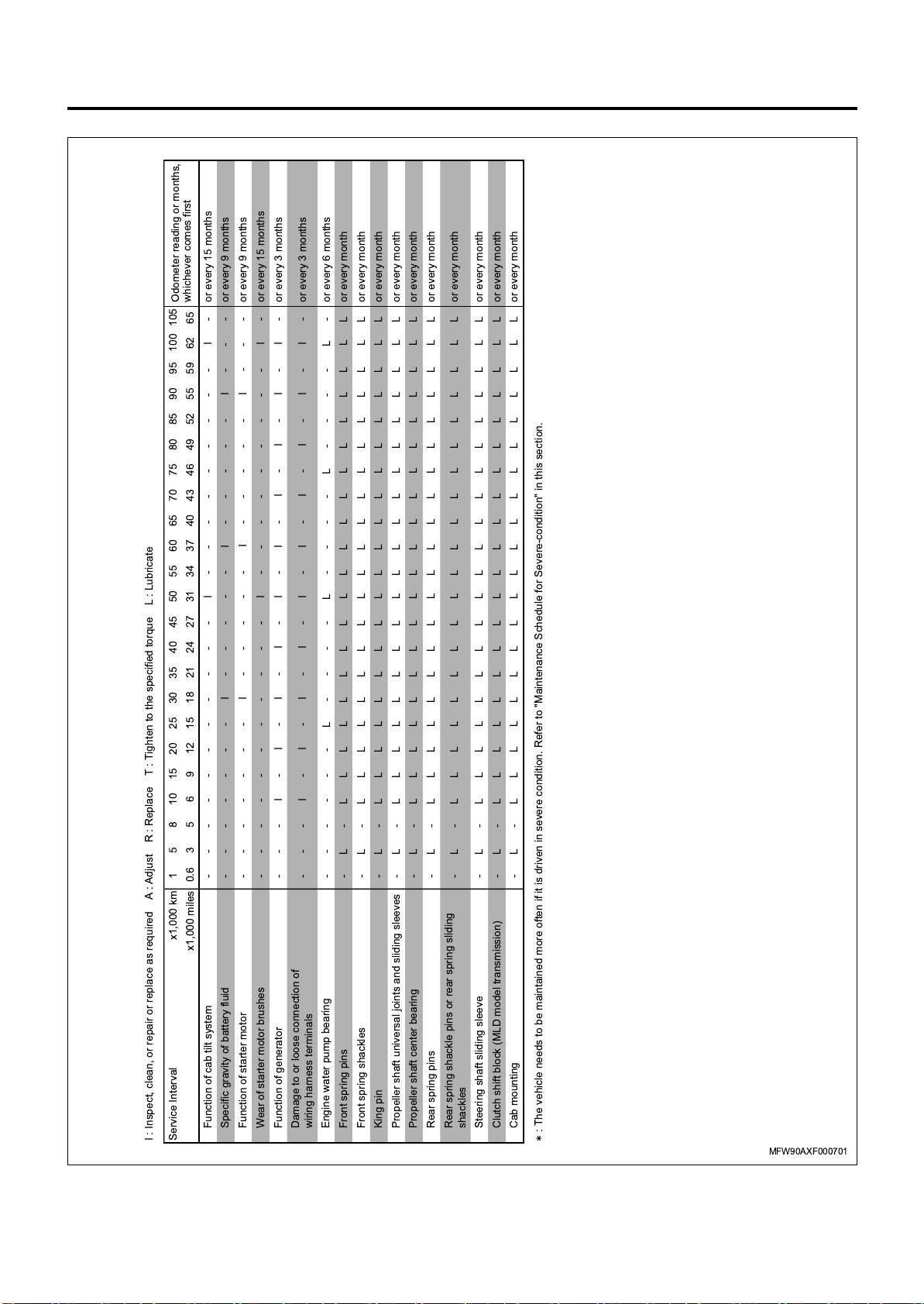
CNG engine for Thailand (4/4)
General Information 0A-57
Odometer reading or months,
whichever comes first
52 55 59 62 65
85 90 95 100 105
or every month
L
I - - - - - I - - - or every 9 months
I : Inspect, clean, or repair or replace as required A : Adjust R : Replace T : Tighten to the specified torque L : Lubricate
Service Interval x1,000 km 1 5 8 10 15 20 25 30 35 40 45 50 55 60 65 70 75 80
x1,000 miles 0.6 3 5 6 9 12 15 18 21 24 27 31 34 37 40 43 46 49
-------I-----I-----I---orevery 9 months
-----------I---------I-orevery 15 months
Function of cab tilt system
Specific gravity of battery fluid
-------I-----
Function of starter motor
- - - I - I - I - I - I - I - I - I - I - I - or every 3 months
-----------I---------I-orevery 15 monthsWear of starter motor brushes
Function of generator
- - - I - I - I - I - I - I - I - I - I - I - or every 3 months
Damage to or loose connection of
wiring harness terminals
------L----L----L----L-orevery 6 months
-L -L LLLLLLLLLLLLLLLLLL
Engine water pump bearing
Front spring pins
-L -L LLLLLLLLLLLLLLLLLLLorevery month
-L -L LLLLLLLLLLLLLLLLLLLorevery month
King pin
Front spring shackles
-L -L LLLLLLLLLLLLLLLLLLLorevery month
-L -L LLLLLLLLLLLLLLLLLLLorevery month
Propeller shaft universal joints and sliding sleeves
Propeller shaft center bearing
-L -L LLLLLLLLLLLLLLLLLLLorevery month
Rear spring pins
-L -L LLLLLLLLLLLLLLLLLLLorevery month
Rear spring shackle pins or rear spring sliding
shackles
-L -L LLLLLLLLLLLLLLLLLLLorevery month
-L -L LLLLLLLLLLLLLLLLLLLorevery month
Steering shaft sliding sleeve
Clutch shift block (MLD model transmission)
-L -L LLLLLLLLLLLLLLLLLLLorevery month
Cab mounting
: The vehicle needs to be maintained more often if it is driven in severe condition. Refer to "Maintenance Schedule for Severe-condition" in this section.
MFW90AXF000701
Page 61

0A-58 General Information
Transmission Oil - ZF6S1000/ZF9S1110 Type
The transmission of the vehicle can stay in good condition through regular maintenance. Above all, make sure to
replace the transmission oil regularly in accordance with the specified maintenance schedule.
Oil Class
Driving Condition
02A 02B 02D/02L
02E
(ZF-Ecofluid M)
Service condition
(local/long-haul transport,
tough operating
conditions)
Normal condition
(long-haul goods
transport)
Change oil at the above-indicated distance or time, whichever comes first.
Low Temperature Limits
Oil Pan Temperature SAE Viscosity Rating Oil Type
- 25°C (- 13°F) or above 80W/80W-85/80W-90 02A/02B
- 40°C (- 40°F) or above 75W/75W-80/75W-85/75W-90 02E (ZF-Ecofluid M)/02D/02L
Oil Classes and Approved Trade Products (except
Europe)
Oil Class 02A
• Gear oil of viscosity grades: SAE 80W/80W-85
/80W-90/85W-90/90
60,000 km
(36,000 miles)
or 12 months
90,000 km
(54,000 miles)
or 12 months
120,000 km
(72,000 miles)
or 12 months
160,000 km
(96,000 miles)
or 12 months
NOTE:
In moderate climate zones, shift quality is impaired if
viscosity grades higher than SAE 80W are used.
240,000 km
(144,000 miles)
or 24 months
300,000 km
(180,000 miles)
or 24 months
Manufacturer (02A) Trade name (02A)
ADDINOL LUBE OIL GMBH, LEUNA/D ADDINOL GETRIEBEÖL GS 80W
ADDINOL LUBE OIL GMBH, LEUNA/D ADDINOL GETRIEBEÖL GS 80W-90
AGIP SCHMIERTECHNIK GMBH, WÜRZBURG/D AUTOL GETRIEBEÖL 80W-90
ARAL AG, BOCHUM/D ARAL GETRIEBEOL EP 80W
ARAL AG, BOCHUM/D ARAL GETRIEBEOL EP 85W-90
AVIA MINERALÖL-AG, MÜNCHEN/D AVIA GEAR OIL MZ 80
AVIA MINERALÖL-AG, MÜNCHEN/D AVIA GEAR OIL MZ 90
BAYWA AG, MÜNCHEN/D BAYWA MEHRZWECKGETRIEBEÖL SAE 80
BAYWA AG, MÜNCHEN/D TECTROL UNIGEAR 80
BEHRAN OIL CO., TEHRAN/IR BEHRAN SAMAND MB 80W-90
BELGIN MADENI YAGLAR, GEBZE KOCAELI/TR BELGEAR EP MB 80
BLASER SWISSLUBE AG, HASLE-RÜEGSAU/CH EP-GETRIEBEÖL 80W-100
BLASER SWISSLUBE AG, HASLE-RÜEGSAU/CH EP-GETRIEBEÖL 80W-68
BLASER SWISSLUBE AG, HASLE-RÜEGSAU/CH EP-GETRIEBEÖL 80W90
BP INTERNATIONAL, PANGBOURNE, READING/GB BP ENERGEAR EP 80W
BP INTERNATIONAL, PANGBOURNE, READING/GB BP ENERGEAR EP 80W-90
BP INTERNATIONAL, PANGBOURNE, READING/GB OJS FRONTOL MEHRZWECK-GETRIEBEÖL MZ
80W-90
BP INTERNATIONAL, PANGBOURNE, READING/GB OJS FRONTOL MEHRZWECKGETRIEBEÖL MZ 80
BUCHER AG LANGENTHAL, LANGENTHAL/CH MOTOREX GEAR OIL EP 80W
BUCHER AG LANGENTHAL, LANGENTHAL/CH MOTOREX GEAR OIL EP 80W/90
Page 62

General Information 0A-59
Manufacturer (02A) Trade name (02A)
CASTROL INTERNATIONAL, PANGBOURNE
READING/GB
CASTROL INTERNATIONAL, PANGBOURNE
READING/GB
CEPSA LUBRICANTS S.A., MADRID/E CEPSA TRANSMISIONES 80W-90
CEPSA LUBRICANTS S.A., MADRID/E ERTOIL TRANSMISIONES 80W-90
CEPSA LUBRICANTS S.A., MADRID/E ERTOIL TRANSMISIONES F SAE 80
CHEVRON BRASIL LTDA., RIO DE JANEIRO/BRAZIL UNIVERSAL EP SAE 80W
CHEVRONTEXACO, GHENT/B GEARTEX EP-A 80W
CHEVRONTEXACO, GHENT/B GEARTEX EP-A 80W-90
CHEVRONTEXACO, GHENT/B GEARTEX EP-A 85W-90
CLAAS KGAA MBH, HARSEWINKEL/D CLAAS AGRISHIFT 4SC 80W90
COMP.BRASIL. D. PETRO. IPIRANGA, RIO DE
JANEIRO/BR
CONDAT LUBRIFIANTS, CHASSE SUR RHONE/F GEAR A (80W)
DE OLIEBRON B.V., ZWIJNDRECHT/NL TOR MULTIPURPOSE GEAR OIL SAE 80W90
EKOIL LTD, UFA/RUS EKOIL ECO TRANS SAE 80W-85 API GL-4
ENI S.P.A. REFINING & MARKETING DIVISION,
ROME/I
ENI S.P.A. REFINING & MARKETING DIVISION,
ROME/I
EXXON MOBIL CORPORATION, FAIRFAX,
VIRGINIA/USA
EXXON MOBIL CORPORATION, FAIRFAX,
VIRGINIA/USA
FUCHS PETROLUB AG, MANNHEIM/D TITAN GEAR MP SAE 80W
GAZPROMNEFT-ONPZ, OMSK/RUS TRANS KP-2 (SAE 80W85)
GAZPROMNEFT-ONPZ, OMSK/RUS TRANS KP-4 (SAE 80W-90)
GULF OIL INTERNATIONAL, PITTSBURG/USA GULF GEAR XP 80W
GULF OIL INTERNATIONAL, PITTSBURG/USA GULF GEAR XP 80W-90
HUILES BERLIET S.A., SAINT PRIEST/F RTO EP 80W
HUILES BERLIET S.A., SAINT PRIEST/F RTO EP 80W-90
IGOL FRANCE SA, AMIENS/F TRANS EPA SAE80W-85W
INDIAN OIL CORPORATION LTD., MUMBAI/IND SERVO GEAR HP 80W(T)
INDIAN OIL CORPORATION LTD., MUMBAI/IND SERVO GEAR HP 80W-90(T)
INDIAN OIL CORPORATION LTD., MUMBAI/IND SERVO GEAR HP 90(T)
KOMPRESSOL-OEL VERKAUFS GMBH, KÖLN/D KOMPRESSOL-MEHRZWECK-GETRIEBEOEL SAE
KRAFFT S.L., ANDOAIN/E HIDROIL SAE 80W90
KROON-OIL B.V., ALMELO/NL GEARLUBE GL-4 80W-90
KUWAIT PETROLEUM R&T B.V., EUROPOORT RT/
NL
KUWAIT PETROLEUM R&T B.V., EUROPOORT RT/
NL
KUWAIT PETROLEUM R&T B.V., EUROPOORT RT/
NL
LIQUI MOLY GMBH, ULM/D LIQUI MOLY GETRIEBEÖL GL 4 SAE 80W
LIQUI MOLY GMBH, ULM/D LIQUI MOLY GETRIEBEÖL GL 4 SAE 85W-90
LLK FINLAND OY, HAMINA/FIN TEBOIL EP SAE 80W
LLK FINLAND OY, HAMINA/FIN TEBOIL EP SAE 80W-90
MAZIVA ZAGREB D.O.O, ZAGREB/HR INA TRANSMOL DB 80W
MAZIVA ZAGREB D.O.O, ZAGREB/HR INA TRANSMOL HD 80W-90
MEGUIN GMBH & CO. KG MINERALOELWERKE,
SAARLOUIS/D
CASTROL EP 80W
CASTROL EP 80W90
IPIRGEROL EP 80W
ROTRA HY 80W-90
ROTRA HY DB 80W
ESSO GEAR OIL GP-D 80W
MOBILUBE GX-A 80W
80W-90
Q8 T 35 SAE 80 W
Q8 T 35 SAE 80W-90
Q8 T 35 SAE 90
MEGOL MEHRZWECKGETRIEBEOEL GL 4 SAE
80W
Page 63

0A-60 General Information
Manufacturer (02A) Trade name (02A)
MEGUIN GMBH & CO. KG MINERALOELWERKE,
SAARLOUIS/D
MOL-LUB KFT., ALMÁSFÜZITÖ/H MOL HYKOMOL 80W
MOTUL SA, AUBERVILLIERS CEDEX/F MOTUL GEAR MB 80W
NESTE MARKKINOINTI OY, ESPOO/FIN NESTE GEAR EP 80W-90
NEW PROCESS AG, TÜBACH/CH EP GEAROIL SAE 80W
OEST, GEORG MINERALÖLWERK,
FREUDENSTADT/D
OEST, GEORG MINERALÖLWERK,
FREUDENSTADT/D
OMV REFINING & MARKETING GMBH, WIEN/A OMV GEAR OIL MP SAE 80W-85
OMV REFINING & MARKETING GMBH, WIEN/A OMV GEAR OIL MP SAE 85W-90
OOO LUKOIL-VOLGOGRADNEFTEPERERABOTKA,
VOLGOGRAD/RUS
OOO LUKOIL-VOLGOGRADNEFTEPERERABOTKA,
VOLGOGRAD/RUS
OPET PETROLCÜLÜK A.S., IZMIR/TR ORSA EP MT 80W
ORLEN OIL SP. Z O.O., KRAKOW/PL HIPOL SUPER GL-4 80W/90
ORLEN OIL SP. Z O.O., KRAKOW/PL PLATINUM GEAR GL-4 80W
ORLEN OIL SP. Z O.O., KRAKOW/PL PLATINUM GEAR GL-4 80W/90
PAKELO MOTOR OIL S.R.L, SAN BONIFACIO (VR)/I PAKELO GEAR OIL EP/FZ SAE 80W
PAKELO MOTOR OIL S.R.L, SAN BONIFACIO (VR)/I PAKELO GEAR OIL EP/FZ SAE 80W/90
PANOLIN AG, MADETSWIL/CH PANOLIN EP GEAR 80W
PANOLIN AG, MADETSWIL/CH PANOLIN EP GEAR 80W/90
PETROGAL S.A., LISBOA/P GALP TRANSOIL 80W90
PETROGAL S.A., LISBOA/P GALP TRANSOIL 80W
PRISTA OIL EAD, ROUSSE/BG PRISTA EP 80W
PT PERTAMINA (PERSERO), JAKARTA/RI RORED EP-A SAE80W-90
PT PERTAMINA (PERSERO), JAKARTA/RI RORED EP-A SAE90
PTT PUBLIC COMPANY LIMITED, BANGKOK/TH PTT EUROTRAN 341 SAE 80W-90
REPSOL YPF LUBRICANTES Y ESPECIALIDADES,
MADRID/E
S-OIL CORPORATION, SEOUL/KOREA DRAGON GEAR TM 80W
S-OIL TOTAL LUBRICANTS CO. LTD., SEOUL/ROK TOTAL EP 80W-90
S.A.E.L., MADRID/E GULF GEAR LUBRICANT 80W-85
SHELL BRASIL, BARRA DA TIJUCA - RIO DE
JANEIRO/BR
SHELL INTERNATIONAL PETROLEUM COMP LTD,
LONDON/GB
SHELL INTERNATIONAL PETROLEUM COMP LTD,
LONDON/GB
SRS SCHMIERSTOFF VERTRIEB GMBH,
SALZBERGEN/D
SRS SCHMIERSTOFF VERTRIEB GMBH,
SALZBERGEN/D
SRS SCHMIERSTOFF VERTRIEB GMBH,
SALZBERGEN/D
TOTAL LUBRIFIANTS S.A., PARIS/F FINA PONTONIC N 80W-85
TOTAL LUBRIFIANTS S.A., PARIS/F FINA PONTONIC N 80W-90
TOTAL LUBRIFIANTS S.A., PARIS/F TOTAL EP 80W-85
TOTAL LUBRIFIANTS S.A., PARIS/F TOTAL EP 80W-90
TOTAL LUBRIFIANTS S.A., PARIS/F TRANSELF EP 80W
TOTAL LUBRIFIANTS S.A., PARIS/F TRANSELF EP 80W-90
UNIL OPAL, SAUMUR CEDEX/F UNIL OPAL GEAR EP SAE 80W85W
YACCO, ST PIERRE LES ELBEUF/F BVX M 100 80W85
MEGOL MEHRZWECKGETRIEBEOEL GL 4 SAE
85W-90
OEST MEHRZWECK-GETRIEBEÖL SAE 80W
OEST MEHRZWECK-GETRIEBEÖL SAE 80W-90
LUKOIL TRANSMISSION TM-4 SAE 80W-85
LUKOIL TRANSMISSION TM-4 SAE 80W-90
CS EP M SAE 80W
SHELL SPIRAX G 80W (IN BRASIL ONLY)
SEHLL SPIRAX EP 80
SHELL SPIRAX MA 80W
SRS WIOLIN MEHRZWECK-GETRIEBEÖL 80
SRS WIOLIN MEHRZWECK-GETRIEBEÖL 80W-90
SRS WIOLIN MEHRZWECK-GETRIEBEÖL 90
Page 64

General Information 0A-61
Manufacturer (02A) Trade name (02A)
YPF S.A., ENSAENADA/RA HELICOIDAL M (80W)
Oil Class 02B
• Gear oil of viscosity grades: SAE 75W-80
/75W-85/75W-90/80W/80W-85/80W-90
/85W-90/90
Manufacturer (02B) Trade name (02B)
ADDINOL LUBE OIL GMBH, LEUNA/D ADDINOL GETRIEBEÖL GX 80 W 90 ML
AGIP SCHMIERTECHNIK GMBH, WÜRZBURG/D AGIP ROTRA TRUCK GEAR S, SAE 75W-90
ARAL AG, BOCHUM/D ARAL GETRIEBEOL EP PLUS 80W-90
ARAL AG, BOCHUM/D ARAL GETRIEBEÖL SNA-E 75W-90
AVIA MINERALÖL-AG, MÜNCHEN/D AVIA SYNTOGEAR FE 75W-90 EP
AVIA MINERALÖL-AG, MÜNCHEN/D AVIA SYNTOGEAR FE 80W-90
BAYWA AG, MÜNCHEN/D BAYWA SUPER 8090 MC
BAYWA AG, MÜNCHEN/D TECTROL MULTIGEAR PLUS 8090
BEHRAN OIL CO., TEHRAN/IR BEHRAN SAMAND OEM 1 80W-90
BP INTERNATIONAL, PANGBOURNE, READING/GB BP ENERGEAR DL 80W-90
BP INTERNATIONAL, PANGBOURNE, READING/GB BP ENERGEAR HT 80W-90
BP INTERNATIONAL, PANGBOURNE, READING/GB ENERGEAR SHX-M SAE 75W-90
BUCHER AG LANGENTHAL, LANGENTHAL/CH GEAR ZX TP SAE 80W/90 GL4/5
BUCHER AG LANGENTHAL, LANGENTHAL/CH MOTOREX UNISYNT TX
CASTROL INTERNATIONAL, PANGBOURNE
READING/GB
CASTROL INTERNATIONAL, PANGBOURNE
READING/GB
CASTROL INTERNATIONAL, PANGBOURNE
READING/GB
CEPSA LUBRICANTS S.A., MADRID/E CEPSA TRANSMISIONES EP FE+LD 75W-90
CHEVRONTEXACO, GHENT/B MULTIGEAR 80W-90
CHEVRONTEXACO, GHENT/B MULTIGEAR S 75W-90
CHEVRONTEXACO, SYDNEY/AUS CALTEX TRANSLUBE LD SAE 80W
CHEVRONTEXACO, SYDNEY/AUS CALTEX TRANSLUBE LD SAE 90
DAF TRUCKS N.V., EINDHOVEN/NL DAF SUPER 80W90
DE OLIEBRON B.V., ZWIJNDRECHT/NL TOR UNIGEAR 75W90 LD
ENI S.P.A. REFINING & MARKETING DIVISION,
ROME/I
ENI S.P.A. REFINING & MARKETING DIVISION,
ROME/I
EXXON MOBIL CORPORATION, FAIRFAX,
VIRGINIA/USA
EXXON MOBIL CORPORATION, FAIRFAX,
VIRGINIA/USA
FALCON OIL COMPANY LTD., SHARJAH/UAE FALCON SUPER EP GEAR OIL 80W/90 GL-4
FINKE MINERALÖLWERK GMBH, VISSELHÖVEDE/
D
FUCHS PETROLUB AG, MANNHEIM/D TITAN SUPERGEAR MC 80W-90
GENOL GMBH & CO., WIEN/A GENOL GEAR-SYN 80W-90
GINOUVES GEORGES SA, LA FARLEDE/F YORK 793 80W90
GINOUVES GEORGES SA, LA FARLEDE/F YORK 896
GRUPA LOTOS SA, GDANSK/PL TITANIS SUPER GL-5 80W/90
GULF OIL INTERNATIONAL, PITTSBURG/USA GULF GEAR MZ 80W
GULF OIL INTERNATIONAL, PITTSBURG/USA GULF GEAR MZ 80W-90
GULF OIL INTERNATIONAL, PITTSBURG/USA GULF GEAR MZ 85W-90
NOTE:
In moderate climate zones, shift quality is impaired if
viscosity grades higher than SAE 80W are used.
CASTROL DYNADRIVE 80W-90
CASTROL DYNADRIVE PLUS 75W90
CASTROL MULTIDRIVE 80W90
ROTRA LSX 75W-90
ROTRA TRUCK GEAR 80W-90
MOBILUBE 1 SHC 75W-90
MOBILUBE S 80W-90
AVIATICON FINKOGEAR SUPER 80W-90
Page 65

0A-62 General Information
Manufacturer (02B) Trade name (02B)
GULF OIL INTERNATIONAL, PITTSBURG/USA GULF GEAR MZ 90
GULF OIL INTERNATIONAL, PITTSBURG/USA GULF GEAR TDL 80W-90
GULF OIL INTERNATIONAL, PITTSBURG/USA GULF SYNGEAR 75W-90
HANDEL MIJ NOVIOL B.V., NIJMEGEN/NL KENDALL TOTAL DRIVE LINE ED 75W90
HUILES BERLIET S.A., SAINT PRIEST/F RTO LONGEVIA P ECO 80W-90
HUILES BERLIET S.A., SAINT PRIEST/F RTO LONGEVIA TCX ECO 75W-90
IGOL FRANCE SA, AMIENS/F GEAR M 80W90
IGOL FRANCE SA, AMIENS/F SYNTHEGEAR SAE75W90
KROON-OIL B.V., ALMELO/NL TRANSMISSION OIL SP 1011
KUWAIT PETROLEUM R&T B.V., EUROPOORT RT/
NL
KUWAIT PETROLEUM R&T B.V., EUROPOORT RT/
NL
LIQUI MOLY GMBH, ULM/D HYPOID GETRIEBEÖL TDL SAE 80W-90
MAZIVA ZAGREB D.O.O, ZAGREB/HR INA HIPENOL SHD 75W-90
MAZIVA ZAGREB D.O.O, ZAGREB/HR INA HIPENOL TDL 80W-90
MEGUIN GMBH & CO. KG MINERALOELWERKE,
SAARLOUIS/D
MEGUIN GMBH & CO. KG MINERALOELWERKE,
SAARLOUIS/D
MILLERS OILS LIMITED, BRIGHOUSE/GB SYNTRAN FE
MINERALÖL-RAFFIN. DOLLBERGEN, UETZEDOLLBERGEN/D
MINERALÖL-RAFFIN. DOLLBERGEN, UETZEDOLLBERGEN/D
MINERALÖL-RAFFIN. DOLLBERGEN, UETZEDOLLBERGEN/D
MODRICA OIL REFINERY, MODRICA/BIH TRANSLUBE GL-4 SAE 80W
MODRICA OIL REFINERY, MODRICA/BIH TRANSLUBE GL-4 SAE 90
MORRIS LUBRICANTS, SHREWSBURY/GB LODEXOL SS 80W
MORRIS LUBRICANTS, SHREWSBURY/GB SERVOL EP 80W/90
MOTUL SA, AUBERVILLIERS CEDEX/F MOTUL GEAR SYNT TDL 75W-90
NESTE MARKKINOINTI OY, ESPOO/FIN NESTE HYPOIDI TDL S 75W-90
NEW PROCESS AG, TÜBACH/CH GEAROIL SYNTH
OEST, GEORG MINERALÖLWERK,
FREUDENSTADT/D
OEST, GEORG MINERALÖLWERK,
FREUDENSTADT/D
OK NEDERLAND, STAPHORST/NL OK UNI-CARDAN OIL LD-SAE 75W/90
OK NEDERLAND, STAPHORST/NL QUINTOL TRANSMISSION OIL VS-45 SAE 75W/90
OMV REFINING & MARKETING GMBH, WIEN/A OMV GEAR OIL XD-4 SAE 80W-85
OMV REFINING & MARKETING GMBH, WIEN/A OMV UNIGEAR S SAE 75W-90
OMV REFINING & MARKETING GMBH, WIEN/A OMV UNIGEAR SAE 80W-90
PAKELO MOTOR OIL S.R.L, SAN BONIFACIO (VR)/I PAKELO GLOBAL GEAR CBS SAE 75W/85
PAKELO MOTOR OIL S.R.L, SAN BONIFACIO (VR)/I PAKELO GLOBAL GEAR SA SAE 80W
PAKELO MOTOR OIL S.R.L, SAN BONIFACIO (VR)/I PAKELO GLOBAL GEAR SA SAE 80W/85
PAKELO MOTOR OIL S.R.L, SAN BONIFACIO (VR)/I PAKELO GLOBAL GEAR SA SAE 80W/90
PAKELO MOTOR OIL S.R.L, SAN BONIFACIO (VR)/I PAKELO GLOBAL GEAR SA SAE 85W/90
PAKELO MOTOR OIL S.R.L, SAN BONIFACIO (VR)/I PAKELO GLOBAL MULTIGEAR TS SAE 75W/90
PANOLIN AG, MADETSWIL/CH PANOLIN SUPER DUTY SYNTH 75W/90
PANOLIN AG, MADETSWIL/CH PANOLIN TOPGEAR 80W/90
PETROGAL S.A., LISBOA/P GALP TRANSVEX TDL 75W90
REPSOL YPF LUBRICANTES Y ESPECIALIDADES,
MADRID/E
S.A.E.L., MADRID/E GULF SYTHETIC GEAR LUBRICANT 75W-90
Q8 GEAR OIL XG SAE 80W-90
Q8 TRANS XGS SAE 75W-90
MEGOL GETRIEBEOEL TRUCK-SYNTH SAE 75W90
MEGOL HYPOID-GETRIEBEOEL TDL SAE 80W-90
PENNASOL MEHRZWECK-GETRIEBEOEL GL 4
SAE 80W
PENNASOL MEHRZWECK-GETRIEBEOEL GL 4
SAE 85W-90
PENNASOL MEHRZWECK-GETRIEBEOEL GL 4
SAE 90
OEST MEHRZWECK-GETRIEBEÖL FE SAE 80W-90
OEST SYNTH GETRIEBEÖL SAE 75W-90
CARTAGO FE LD 75W90
Page 66

General Information 0A-63
Manufacturer (02B) Trade name (02B)
SHARJAH NATIONAL LUBE OIL CO. LTD.,
SHARJAH/UAE
SHELL INTERNATIONAL PETROLEUM COMP LTD,
LONDON/GB
SHELL INTERNATIONAL PETROLEUM COMP LTD,
LONDON/GB
SHELL INTERNATIONAL PETROLEUM COMP LTD,
LONDON/GB
SRS SCHMIERSTOFF VERTRIEB GMBH,
SALZBERGEN/D
SRS SCHMIERSTOFF VERTRIEB GMBH,
SALZBERGEN/D
STATOIL LUBRICANTS, STOCKHOLM/S GEARWAY G4 80W
STRUB + CO AG, REIDEN/CH STRUB MULTIGEAR SGO 80W-90
STRUB + CO AG, REIDEN/CH VULCOGEAR SYNT SGX 75W-90
TEDEX PRODUCTION SP.Z.O.O., TOMASZOW
MAZOWIECKI/PL
TEDEX PRODUCTION SP.Z.O.O., TOMASZOW
MAZOWIECKI/PL
TOTAL LUBRIFIANTS S.A., PARIS/F FINA PONTONIC FDL 75W-90
TOTAL LUBRIFIANTS S.A., PARIS/F TOTAL TRANSMISSION MDL 80W-90
TOTAL LUBRIFIANTS S.A., PARIS/F TOTAL TRANSMISSION RS FE 80W-90
TOTAL LUBRIFIANTS S.A., PARIS/F TOTAL TRANSMISSION SYN FE 75W-90
TOTAL LUBRIFIANTS S.A., PARIS/F TRANSELF SYNTHESE FE 75W-90
TOTAL LUBRIFIANTS S.A., PARIS/F TRANSELF UNIVERSAL FE 80W-90
VALVOLINE EUROPE, DORDRECHT/NL SYNPOWER GEAR OIL TDL 75W-90
VIAL OIL LTD., MOSCOW/RUS CONSOL TRANS LUX SAE 75W-90
VIAL OIL LTD., MOSCOW/RUS CONSOL TRANS LUX SAE 80W-90
YACCO, ST PIERRE LES ELBEUF/F BVX 1000
ZELLER + GMELIN GMBH & CO., EISLINGEN/D DIVINOL GEAR OIL STO SAE 80W-90
ZF FRIEDRICHSHAFEN AG, FRIEDRICHSHAFEN/D ZF-ECOFLUID X
SHARLU EP GEAR LUBE 80W/90 (GL-4)
SHELL SPIRAX GX 80W
SHELL SPIRAX GX 80W-90
SHELL SPIRAX MX 80W-90
SRS GETRIEBEFLUID SML 80W-90
SRS WIOLIN RSG 80
TEDEX GEAR OIL SAE 80W
TEDEX SUPER GEAR OIL (3343M) SAE 80W90
Oil Class 02D
• Gear oil of viscosity grades: SAE 75W-80 (semisynthetic, synthetic)
Manufacturer (02D) Trade name (02D)
AGIP SCHMIERTECHNIK GMBH, WÜRZBURG/D AUTOL GETRIEBEÖL VSL-4 75W-80
ARAL AG, BOCHUM/D ARAL GETRIEBEÖL SNS SAE 75W-80
AVIA MINERALÖL-AG, MÜNCHEN/D AVIA MULTIGEAR SL 75W-80W
BP INTERNATIONAL, PANGBOURNE, READING/GB CASTROL SYNTRANS Z
BUCHER AG LANGENTHAL LANGENTHAL/CH MOTOREX PRISMA TF 75W/80
CEPSA LUBRICANTS S.A., MADRID/E CEPSA TRANSMISIONES FE+LD 75W-80
CHEVRONTEXACO, GHENT/B MULTIGEAR MTF 75W-80W
COMERCIAL ROSHFRANS, S.A. DE C.V., MEXICO,
D.F/MEX
DAF TRUCKS N.V., EINDHOVEN/NL DAF PREMIUM 75W80W
DE OLIEBRON B.V., ZWIJNDRECHT/NL TOR MT/LD GEAR OIL 75W80
ENI S.P.A. REFINING & MARKETING DIVISION,
ROME/I
EXXON MOBIL CORPORATION, FAIRFAX,
VIRGINIA/USA
FUCHS PETROLUB AG, MANNHEIM/D TITAN CYTRAC LD 75W-80
GINOUVES GEORGES SA, LA FARLEDE/F YORK 894 75W-80
GULF OIL INTERNATIONAL, PITTSBURG/USA GULF GEAR TX 75W-80
GEAR OIL EUROFLEET SAE 75W-80
ROTRA MULTIGEAR 75W-80
MOBILUBE XHP 75W-80
Page 67

0A-64 General Information
Manufacturer (02D) Trade name (02D)
HANDEL MIJ NOVIOL B.V., NIJMEGEN/NL KENNOCO FLEET TRANSMISSION LUBE ED SAE
75W-80W
HUILES BERLIET S.A., SAINT PRIEST/F RTO LONGEVIA ECO 75W-80
IGOL FRANCE SA, AMIENS/F TRANS GEAR ZF 75W80
KROON-OIL B.V., ALMELO/NL GEAR SYNTH MT/LD 75W-80
KUWAIT PETROLEUM R&T B.V., EUROPOORT RT/
NL
LIQUI MOLY GMBH, ULM/D HOCHLEISTUNGS-GETRIEBEÖL GL 3+ SAE 75W-
MAZIVA ZAGREB D.O.O, ZAGREB/HR INA TRANSMOL HD 75W-80
MEGUIN GMBH & CO. KG MINERALOELWERKE,
SAARLOUIS/D
MOTUL SA, AUBERVILLIERS CEDEX/F MOTUL MOTYLGEAR 75W-80
OK NEDERLAND, STAPHORST/NL OK CARDAN OIL MT/LD SAE 75W/80
OMV REFINING & MARKETING GMBH, WIEN/A OMV GEAR OIL LDI SAE 75W-80
PAKELO MOTOR OIL S.R.L, SAN BONIFACIO (VR)/I PAKELO GOLDENGEAR LD SAE 75W/80
PANOLIN AG, MADETSWIL/CH TRANSGEAR 75W/80W
PETROGAL S.A., LISBOA/P GALP TRANSVEX TDL ULTRA 75W80
PETRONAS LUBRICANTS INTERN., KUALA
LUMPUR/MAL
PETRONAS LUBRICANTS INTERN., KUALA
LUMPUR/MAL
RALOY LUBRICANTES S.A. DE C.V.,
TIANGUISTENCO/MEX
REPSOL YPF LUBRICANTES Y ESPECIALIDADES,
MADRID/E
S.A.E.L., MADRID/E GULF INTARDER GEAR OIL 75W-80
SHELL INTERNATIONAL PETROLEUM COMP LTD,
LONDON/GB
TOTAL LUBRIFIANTS S.A., PARIS/F FINA PONTONIC TI 75W-80
TOTAL LUBRIFIANTS S.A., PARIS/F TOTAL TRANSMISSION TI 75W-80
TOTAL LUBRIFIANTS S.A., PARIS/F TRANSELF LD 75W-80
UNIL OPAL, SAUMUR CEDEX/F GERION LD 75W80
VALVOLINE EUROPE, DORDRECHT/NL DURABLEND GEAR OIL GL-4 SAE 75W-80
YACCO, ST PIERRE LES ELBEUF/F BVX Z-500 75W-80
Q8 T 60 SAE 75W-80
80
MEGOL HOCHLEISTUNGSGETRIEBEOEL GL 4 SAE
75W-80
TUTELA TRUCK GEAR FE (SAE 75W80)
TUTELA TRUCK GEARLITE SAE 75W80
NEW EXPERIENCE SYNTHETIC OIL 341
REPSOL CARTAGO FE LD 75W-80
SHELL TRANSMISSION OIL ZFLD 75W-80
Oil Class 02E
• Gear oil of viscosity grades: SAE 75W-80
(synthetic)
Manufacturer (02E) Trade name (02E)
CASTROL INTERNATIONAL, PANGBOURNE
READING/GB
ZF FRIEDRICHSHAFEN AG, FRIEDRICHSHAFEN/D ZF-ECOFLUID M
Oil Class 02L
• Gear oil of viscosity grades: SAE 75W-80 (semisynthetic, synthetic)
Manufacturer (02L) Trade name (02L)
BAYWA AG, MÜNCHEN/D TECTROL SYNTOGEAR MA 7580
FUCHS PETROLUB AG, MANNHEIM/D FUCHS TITAN CYTRAC MAN SYNTH 75W-80
HUILES BERLIET S.A., SAINT PRIEST/F RTO LONGEVIA BZV ECO 75W-80
TOTAL LUBRIFIANTS S.A., PARIS/F TOTAL TRANSMISSION XS FE 75W-80
CASTROL SYNTRANS MAX 75W-80
Page 68

General Information 0A-65
About Oil Types (for Europe)
• Oil Class 02A
Oils with a viscosity corresponding to any of the
following numbers :
SAE 80W/80W-85/80W-90/85W-90/90
NOTE:
If you use a transmission oil with a viscosity number of
SAE 80W or above in a moderate ambient temperature
condition, gears will become difficult engage.
• Oil Class 02B
Oils with a viscosity corresponding to any of the
following numbers :
SAE 75W-80/75W-85/75W-90/80W/80W-85/80W90/85W-90/90
NOTE:
If you use a transmission oil with a viscosity number of
SAE 80W or above in a moderate ambient temperature
condition, gears will become difficult engage.
•Oil Class 02D
Semi-synthetic and synthetic oils with a viscosity
corresponding to the following number :
SAE 75W-80
•Oil Class 02L
Semi-synthetic and synthetic oils with a viscosity
corresponding to any of the following number :
SAE 75W-80
• Oil Class 02E (ZF-Ecofluid M)
Synthetic oils with a viscosity corresponding to any
of the following number :
SAE 75W-80
Transmission Oil - FS8209A/FSO5206B Type
Carry out periodic maintenance on the transmission in order to maintain its original performance. It is particularly
important to replace the transmission oil according to the Maintenance Schedule.
The Maintenance Schedule varies according to the type of oil used.
Mineral Oil
Operating
conditions
Highway
use
Off-highway
use
Recommended lubricants
Type Grade (SAE) Outside temperature
Heavy Duty Engine Oil
API-CD
Replacement interval Inspection and replacement item
First 5,000 to 10,000 km
(3,000 to 6,000 miles)
or every 12 months
Change transmission oil at the driver’s discretion
Every 20,000 km
(12,000 miles)
Every 100,000 km
(62,000 miles)
First 30 hours Change transmission oil at the driver’s discretion
Every 40 hours Check oil level and inspect for leakage
Every 500 hours Change transmission oil (driving on unpaved roads)
Every 1,000 hours Change transmission oil (driving on normal paved roads)
Check oil level and inspect for leakage
Change transmission oil
50 - 12°C (10°F) or higher
40 - 12°C (10°F) or higher
30 Up to - 12°C (10°F)
Mild EP Gear Oil
API-GL-4
90 - 12 to 38°C (10 to 100°F)
80W - 26 to 21°C (-15 to 70°F)
Page 69

0A-66 General Information
Synthetic Oil
Operating
conditions
Highway
use
Off-highway
use
Recommended oil
• COGNIS (HENKEL/EMERY)MTF4200
Semi-Synthetic Oil
Replacement interval Inspection and replacement item
Every 20,000 km
(12,000 miles)
Every 500,000 km
(300,000 miles)
or 36 months
Every 400,000 km
(240,000 miles)
or 36 months
Every 300,000 km
(180,000 miles)
or 36 months
Every 40 hours
Every 500 hours
Every 36 months
Check oil level and inspect for leakage
(all recommended oils)
Change transmission oil
[when COGNIS (HENKEL/EMERY)MTF4200 is used]
Change transmission oil
[when CASTROL SYNTRANS is used]
Change transmission oil
[when MOBILUBE 1 SHC is used]
Check oil level and inspect for leakage
(all recommended oils)
Change transmission oil
(all recommended oils; driving on unpaved roads)
Change transmission oil
(all recommended oils; driving on normal paved roads)
• CASTROL SYNTRANS
•MOBILUBE 1 SHC
Operating
conditions
Highway
use
Off-highway
use
Recommended oil
• ELF TRANSELF 75W/80W (known as RVI
Longevia)
• MOBIL MOBILUBE XHP
• KUWAIT Q8 T 60
• FUCHS DEA DEAGEAR LD & TITAN CYTRAC LD
• FIAT LUBRIFICANTI TUTELA TRUCK GEAR FE
• DE OLIEBRON TOR MT/LD GEAR OIL
• OMV AKTIENGESELLCHAFT OMVLDL 75W-80
• PAKELO MOTOR OIL PAKELO GOLDENGEAR
LD
• TEXACO MULTIGEAR MTF 75W/80W
Replacement interval Inspection and replacement item
Every 20,000 km
(12,000 miles)
Every 300,000 km
(180,000 miles)
or 36 months
Every 40 hours
Every 500 hours
Every 36 months
Check oil level and inspect for leakage
(all recommended oils)
Change transmission oil
(all recommended oils)
Check oil level and inspect for leakage
(all recommended oils)
Change transmission oil
(all recommended oils; driving on unpaved roads)
Change transmission oil
(all recommended oils; driving on normal paved roads)
NOTE:
• When an oil filter elements is installed, replace it
when changing the oil.
• If your vehicle is used under service conditions,
change the oil accordingly.
Page 70

RS23/RS40 Type Axle
The differential gear of your vehicle can stay in good
conditions through regular maintenance. Above all,
make sure to replace the differential oil and filter
element regularly in accordance with the specified
maintenance schedule.
General Information 0A-67
Driving
conditions
Off-highway
use
Highway
use
Recommended Oil
Type API/MIL rating SAE viscosity rating
Mineral oil (O-76A) GL5/MIL-L-2105D SAE 85W-140
Synthetic oil (O-76M)
Inspection and refilling
(as required)
Every 5,000 km
(3,000 miles)
Every 5,000 km
(3,000 miles)
(if approved by the body manufacturer)
Differential oil change
After first 5,000 km
(3,000 miles)
or first regular service time
(whichever is earlier)
After first 5,000 km
(3,000 miles)
or first regular service time
(whichever is earlier)
GL5/MIL-L-2105D
Differential oil change and
filter element replacement
Every 80,000 km
(whichever is earlier)
Every 160,000 km
(100,000 miles)
(whichever is earlier)
SAE 75W-140/75W-90
(50,000 miles)
or 6 months
or 6 months
Page 71

0A-68 General Information
RS25 Type Axle
The differential gear of your vehicle can stay in good
conditions through regular maintenance. Above all,
make sure to replace the differential oil and filter
element regularly in accordance with the specified
maintenance schedule.
Check and Replacement Interval
Construction, Refuse, Yard
Vocation or Vehicle
Operation
Initial Oil Change Not required Not required Not required
Line-haul City Delivery
Tractor, Logging, Heavy
Haul, Mining, Oil Field,
Rescue
Check Oil Level
Add the correct type
and amount of oil as
required.
Petroleum-Based Oil
Change on Axles
Synthetic Oil
Change on Axles [2]
[1] For continuous heavy-duty operation, check the oil level every 1,600 km (1,000 miles).
[2] These intervals apply to approved semi-synthetic and full-synthetic oils only. For a list of approved extended-
drain axle oils, refer to TP-9539, Approved Rear Drive Axle Lubricants.
Recommended Oil
Type API/MIL rating SAE viscosity rating
Every 40,000 km
(25,000 miles)
or the fleet maintenance
interval, whichever comes
first
Every 160,000 km
(100,000 miles)
or annually, whichever
comes first
Every 800,000 km
(500,000 miles)
or every 4 years, whichever
comes first
Every 16,000 km
(10,000 miles),
once a month or the fleet
maintenance interval,
whichever comes first
Every 80,000 km (50,000
miles) or annually,
whichever comes first
Every 400,000 km
(250,000 miles)
or every 3 years, whichever
comes first
Every 8,000 km
(5,000 miles),
once a month or the fleet
maintenance interval,
whichever comes first [1]
Every 40,000 km
(25,000 miles)
or annually, whichever
comes first
Every 160,000 km
(100,000 miles)
or every 2 years, whichever
comes first
Mineral oil (O-76A) GL5/MIL-L-2105D SAE 85W-140
Synthetic oil (O-76M)
(if approved by the body manufacturer)
GL5/MIL-L-2105D
SAE 75W-140/75W-90
Page 72

Maintenance Schedule for Severe-condition
Introduction
The vehicle needs to be maintained more often if it is
driven in severe condition.
A : Driving with a trailer
B : Operation involving frequent starts and stops
C : Driving on rough roads, mountain roads or uphill
roads
D : Driving in dusty areas
Driving on snowy roads or along the seashore
Maintenance Schedule for Severe-condition
General Information 0A-69
Engine Oil
Item Distance covered
Air Cleaner Element
4HK1 Engine model
6HK1 Engine model
(Except 6HK1-TCN/TCC
Engine model for Australia)
6HK1-TCN/TCC Engine
model for Australia
Replace
every 24,000 km
(15,000 miles)
or
after 6th cleaning
Change
every 10,000 km
(6,000 miles)
Change
every 10,000 km
(6,000 miles)
[Engine oil SAE
10W-40 is
recommended for
use]
Condition
ABCDEB+E
D
ADB+E
If one of the following applies to the
usage conditions.
• The length of time for PTO use is
20% or longer of the engine
operating time.
• The length of time for idling is 50%
or longer of the engine operating
time.
• The average vehicle speed is 10
km/h(6 MPH) or slower.
6HF1 Engine model
for Thailand
6HF1 Engine model
(When using ISUZU genuine
for Australia)
6HF1 Engine model
(When using FUCHS for
Australia)
Change
every 5,000 km
(3,000 miles)
Change
every 10,000 km
(6,000 miles)
Change
every 5,000 km
(3,000 miles)
ADB+E
ADB+E
ADB+E
Page 73

0A-70 General Information
Item Distance covered
4HK1 Engine model
6HK1 Engine model
6HF1 Engine model
for Thailand
Engine Oil Filter
6HF1 Engine model
(When using ISUZU genuine
engine oil for Australia)
6HF1 Engine model
(When using FUCHS engine
oil for Australia)
Engine Oil Separator
(6HK1 Engine model for Euro3 specification)
(4HK1 Engine model for Euro4 / Euro3 specification)
Loose or otherwise improper installation
of Exhaust Pipe
MZX/MZW/MZZ model
Change
every 10,000 km
(6,000 miles)
Change
every 5,000 km
(3,000 miles)
Change
every 10,000 km
(6,000 miles)
Change
every 5,000 km
(3,000 miles)
Change
every 10,000 km
(6,000 miles)
Inspect
every 2,000 km
(1,250 miles)
Replace
every 24,000 km
(15,000 miles)
Condition
ABCDEB+E
ADB+E
ADB+E
ADB+E
ADB+E
ADB+E
ABC E
AC
Transmission Oil
Transmission Fluid
Transmission
Main Filter
Replace
MLD model
ZF6S1000 model Refer to “Maintenance Schedule” in this section.
ZF9S1110 model Refer to “Maintenance Schedule” in this section.
FSO5206B model Refer to “Maintenance Schedule” in this section.
FS8209A model Refer to “Maintenance Schedule” in this section.
ALLISON2500 model
ALLISON3000/3500 model
ALLISON2500 model
ALLISON3000/3500 model
every 24,000 km
(15,000 miles)
Replace
every 20,000 km
(12,000 miles)
Replace
every 20,000 km
(12,000 miles)
Replace
every 20,000 km
(12,000 km),
500 hours
or 6 months
Replace
every 20,000 km
(12,000 km),
500 hours
or 6 months
AC
ABC
ABC
ABC
ABC
Page 74

General Information 0A-71
Item Distance covered
ALLISON2500 model
Transmission
Cooling System
Filter
ALLISON3000/3500 model
Clutch fluid Manual Transmission Vehicle
Smoother
Clutch Oil
Transfer
Gear Case Oil
Vehicle equipped
with the Smoother System
4WD model
Replace
every 20,000 km
(12,000 km),
500 hours
or 6 months
Replace
every 20,000 km
(12,000 km),
500 hours
or 6 months
Change
every 24,000 km
(15,000 miles)
Change
every 24,000 km
(15,000 miles)
Replace
every 12,000 km
(7,500 miles)
Condition
ABCDEB+E
ABC
ABC
B
AC
AC
Worn Propeller Shaft Universal Joints
and Splines
Rear Axle Differential
Gear Oil
Rear Axle Differential Oil
Rear Wheel Hub
Bearing Oil
Inter-differential
Gear Oil
Front Axle Differential
Gear Oil
Front Wheel Hub
Bearing Oil
ARVIN MERITOR
ARVIN MERITOR
ARVIN MERITOR
Vehicle equipped
with ISUZU
produced Axle
FVR model
with
produced Axle
FVM model
with
produced Axle
FVZ model
4WD model
Vehicle equipped
with
produced Axle
Inspect
every 24,000 km
(15,000 miles)
Change
every 24,000 km
(15,000 miles)
Refer to “Maintenance Schedule” in this section
Change
every 24,000 km
(15,000 miles)
Change
every 24,000 km
(15,000 miles)
Change
every 24,000 km
(15,000 miles)
Replace
every 24,000 km
(15,000 miles)
AC
for RS25 type axle.
AC
AC
AC
AC
C
Leaf Spring U-bolt Nuts
Tighten to the
Specified Torque
every 24,000 km
(15,000 miles)
C
Page 75

0A-72 General Information
Item Distance covered
Air Suspension’s Beam Bolt
Nuts/U-bolt Nuts
Loose or damaged air
suspension main support
members
Damage to, or Looseness or
Excessive Play
in Power Steering Joint
Brake Lining Wear
Brake Drum Wear or Damage
Air Suspension
model
Air Suspension
model
except Europe
for Europe
Tighten to the
Specified Torque
every 24,000 km
(15,000 miles)
Inspect
every 24,000 km
(15,000 miles)
Inspect
every 6,000 km
(3,750 miles)
Inspect
every 2,500 km
(1,500 miles)
Inspect
every 2,500 km
(1,500 miles)
Inspect
every 20,000 km
(12,000 miles)
Condition
ABCDEB+E
C
C
C
C
ABCD
ABCD
Brake Pad Wear
(Vehicle equipped with Disc Brake)
Brake Disc Wear or Damage
(Vehicle equipped with Disc Brake)
Inspect
every 2,500 km
(1,500 miles)
Inspect
every 20,000 km
(12,000 miles)
or every 6 months
ABCD
ABCD
Page 76

General Information 0A-73
Recommended Fluids, Lubricants and Diesel Fuels (except Europe)
Introduction
In order to obtain the maximum performance and the
longest service life from your ISUZU vehicles, it is very
important to select and use correctly best lubricant and
diesel fuels.
When lubricating, be sure to use ISUZU genuine
lubricants or recommended lubricants listed below,
according to the maintenance schedule for each
vehicle model.
The lubrication intervals in the maintenance schedule
and the coverage and period of new vehicle warranty
are based on the use of ISUZU genuine lubricants or
recommended lubricants as given in the chart which
will serve as a guide for selecting lubricants of proper
brand name.
Diesel Engine Crankcase with DPD (Low Ash Oil)
MAKE BRAND
ISUZU GENUINE BESCO CLEAN SUPER (10W-40) DH-2
ISUZU GENUINE BESCO CLEAN (10W-30, 40) DH-2
Shell Rimula R6 LM (10W-40)
ExxonMobil Delvac XHP LE (10W-40) E6
ExxonMobil Delvac MX ESP (15W-40) CJ-4 DH-2
ExxonMobil Delvac 1300 Super (15W-40) CJ-4 DH-2
Castrol Tection Global ES (15W-40) CJ-4
BP Vanellus Eco (10W-40) E6
BP Vanellus Multi Fleet Eco (15W-40) CJ-4
Caltex/Chevron/
Texaco
Caltex/Chevron/
Texaco
Caltex/Chevron/
Texaco
Delo 400 LE (15W-40) CJ-4 E9 DH-2
Delo XLE Multigrade (10W-40) E6/E7
Ursa Ultra X (10W-40) E6/E7
API ACEA JASO
CI-4/CH-4/
CG-4/CF-4/CFE7/E6/E4 DH-2
GRADE
NOTE:
The oils recommended in the "Diesel Engine
Crankcase" list can also be used for DPD-equipped
vehicles.
If you use a low ash content engine oil, increased
exhaust pressure may extend the required distance
between DPD filter cleanings.
Page 77

0A-74 General Information
Diesel Engine Crankcase without DPD
MAKE BRAND
ISUZU GENUINE BESCO MULTI-Z TYPE CF-4 (10W-30) CF-4
ISUZU GENUINE BESCO S-3 (10W), (20W), (30), (40) CD
Shell Rimula R3X (15W-40)
Shell Rimula R2 Extra (15W-40) CF-4/CF E2
Shell Rimula R2 (30), (40) CF
Shell Rimula Ultra XT (5W-40)
ExxonMobil Mobil Delvac MX (15W-40) CI-4
Castrol Tection J-Max (15W-40) CH-4 E3 DH-1
BP Vanellus C6 Extra (15W-40) CH-4 E3/E5
Caltex/Chevron Delo Gold (30), (40) CF E2
Caltex/Chevron Delo Gold Multigrade (15W-40) CH-4/CF E3
Caltex/Chevron Delo 400 Multigrade (15W-40) CI-4 Plus E7 DH-1
API ACEA JASO
CH-4/CG-4
CF-4/CF
CH-4/CG-4/
CF-4/CF
GRADE
E5/E3 DH-1
CNG Engine Crankcase (for Australia)
MAKE BRAND
ISUZU GENUINE BESCO CNG ENGINE OIL (10W-30)
FUCHS TITAN CNG MC (10W-40)
CNG Engine Crankcase (for Thailand)
MAKE BRAND
ISUZU GENUINE BESCO CNG ENGINE OIL (10W-30)
PTT DYNAMIC LA (15W-40)
GRADE
API ACEA JASO
GRADE
API ACEA JASO
Page 78

Manual Transmission (MZX/MZW/MLD
models), Transfer Case, Differential (without LSD) and Oil Lubricated Hub Bearing
General Information 0A-75
MAKE BRAND
API ACEA JASO
ISUZU GENUINE BESCO GEAR OIL SH (80W-90), (90), (140) GL-5
ExxonMobil Mobilube HD (80W-90) GL-5
Castrol Dynadrive (80W-90) GL-5
BP Hypogear (80W-90) GL-5
Caltex Thuban GL-5 EP (80W-90), (85W-140) GL-5
Manual Transmission (MZZ models)
MAKE BRAND
API ACEA JASO
ISUZU GENUINE BESCO GEAR OIL SH (80W-90), (90) GL-5
ExxonMobil Mobilube HD (80W-90) GL-5
Castrol Dynadrive (80W-90) GL-5
BP Hypogear (80W-90) GL-5
Caltex Thuban GL-5 EP (80W-90) GL-5
GRADE
GRADE
Differential (with LSD)
MAKE BRAND
API ACEA JASO
Shell Spirax A LS 90 (90) GL-5
ExxonMobil Mobilube LS (85W-90) GL-5
Castrol LSX (85W-140) GL-5
BP Limslip (85W-140) GL-5
Caltex Gear Oil LSD (90) GL-5
Smoother Clutch Oil (Smoother)
MAKE BRAND
API ACEA JASO
ISUZU GENUINE BESCO ATF III
GRADE
GRADE
Page 79
0A-76 General Information
Automatic Transmission, Power Steering
MAKE BRAND
ISUZU GENUINE BESCO ATF II (Power Steering only)
ISUZU GENUINE BESCO ATF III
Shell Donax TG (Dexron
Castrol TQ DIII (Dexron
BP Autoran DXIII (Dexron
Caltex/Texaco Texamatic 1888 (Dexron
III)
III)
III)
III)
Center Bearing, Clutch Shift Block, Grease
Lubricated Hub, Water Pump, Propeller
Shaft Sliding Yoke, Universal Joint (Multi
Purpose Grease)
MAKE BRAND
ISUZU GENUINE BESCO L-2 GREASE (No.2)
GRADE
API ACEA JASO
GRADE
API ACEA JASO
ISUZU GENUINE BESCO L-3 GREASE (No.3)
Shell Retinax LX2 (No.2)
ExxonMobil Mobilgrease XHP 222/223 (No.2), (No.3)
Caltex/Texaco Starplex-2 (No.2)
Multi-Purpose Grease Containing Molybdenum
MAKE BRAND
API ACEA JASO
Shell Retinax HDX2 (No.2)
Caltex Molytex Grease EP2 (No.2)
Engine Cooling System
MAKE BRAND
ISUZU GENUINE BESCO LLC SUPER TYPE E, AS
GRADE
Caltex/Texaco/Chevron Extended Life Coolant
Caltex/Texaco/Chevron Havoline XLC
Caltex/Texaco/Chevron Delo ELC
Page 80

General Information 0A-77
Engine coolant prevents engine damage due to
freezing and protects the cooling system from
corrosion. Use a mixture of the engine coolant
concentrate solution and distilled water or deionized
water as the engine coolant. Use only an Isuzurecommended engine coolant solution. Mix with for 30
or 50% solution and the rest water.
Coolant concentration
Usage region Outside temperature
Isuzu genuine coolant
Warm region Up to -12°C(10°F) 30% 50%
Cold region Up to -30°C(-22°F) 50% 50%
Other than Isuzu
genuine coolant*
*For other than Isuzu genuine coolant(TEXACO/
CALTEX/CHEVRON, etc.), it is recommended to use
directly “ 50/50 Pre-diluted” product which is already
diluted to 50% concentration.
If the mixture contains over 60% engine coolant, the
possibility of overheating increases; conversely, if the
mixture contains less than 30%, protection against
corrosion will be inadequate. Accordingly, the mixture
should contain between 30% and 50% engine coolant.
NOTE:
• If the engine or vehicle is used at -30°C(-22°F) or
below, the coolant concentration of 55% is
recommended.
• Using coolant at any coolant concentration other
than that specified may reduce anti-freezing
performance, and engine coolant may freeze.
Electric-hydraulic Cab Tilt Pump
GRADE
MIL-H-5606E aviation oil or equivalent
Clutch and Brake Fluid Reservoir
MAKE BRAND GRADE*
ISUZU GENUINE BESCO brake fluid super DOT 3
AC Delco
TM
Delco supreme11 DOT 3
* : This material meets GENERAL MOTORS
ENGINEERING STANDARDS GM4653M,FMVSS 116
or SAE J1703 requirements.
Diesel Fuel / Applicable Standard
Japanese Industrial Standards (JIS) Based on K2204 : 1997 Diesel Fuel
Deutsche Industrie Normen (DIN) Based on EN590 : 1997
American Society for Testing and Materials (ASTM) Based on D975-04c NO.1-D S500 or NO.2-D
S500 (below 500 ppm)
British Standards (BS) Based on EN590 : 1997
Page 81

0A-78 General Information
Diesel Fuel / Applicable Standard (Sulfur content below 50 ppm)
Japanese Industrial Standards (JIS) Based on K2204 : 2007 Diesel Fuel
Deutsche Industrie Normen (DIN) Based on EN590 : 2004
American Society for Testing and Materials (ASTM) Based on D975-04c NO.1-D S15 or NO.2-D S15
(below 15 ppm)
British Standards (BS) Based on EN590 : 2004
CAUTION:
Be sure to use low-sulfur diesel fuel (with sulfur content
no higher than 50 ppm) or extra-low-sulfur diesel fuel
(with sulfur content no higher than 10 ppm).
If you supply the vehicle with poor-quality fuel, waterremoval additive or other additive, gasoline, kerosene
or alcohol-based fuel, it could harm the fuel filter,
prevent proper movement of fuel-lubricated parts in the
injectors and adversely affect engine components,
possibly resulting in a breakdown.
If you accidentally put the wrong fuel in the tank, drain it
all out. Starting the engine with the wrong fuel in the
tank could result in a fire and engine damage.
Page 82

General Information 0A-79
Recommended Fluids, Lubricants and Diesel Fuels (for Europe)
Introduction
In order to obtain the maximum performance and the
longest service life from your ISUZU vehicles, it is very
important to select and use correctly best lubricant and
diesel fuels.
When lubricating, be sure to use lubricants listed below,
according to the maintenance schedule for each
vehicle model.
The lubrication intervals in the maintenance schedule
and the coverage and period of new vehicle warranty
are based on the use of lubricants whose grade is listed
in the chart which will serve as a guide for selecting
lubricants of proper brand name.
Diesel Engine Crankcase with DPD (Low Ash Oil)
GRADE
API ACEA JASO OTHER
CJ-4 E6 DH-2
E9
NOTE:
The oils recommended in the "Diesel Engine
Crankcase" list can also be used for DPD-equipped
vehicles.
If you use a low ash content engine oil, increased
exhaust pressure may extend the required distance
between DPD filter cleanings.
Diesel Engine Crankcase without DPD
GRADE
API ACEA JASO OTHER
CF E4 DH-1
CF-4 E7
CH-4
CI-4
Page 83

0A-80 General Information
Manual Transmission (MZX/MZW/MZZ/MLD models), Differential (without LSD) and Oil Lubricated Hub Bearing
GRADE
API ACEA JASO OTHER
GL-5 BESCO GEAR OIL SH (80W-90), (90), (140) (ISUZU GENUINE)
Mobilube HD (80W-90) (ExxonMobil)
Dynadrive (80W-90) (Castrol)
Hypogear (80W-90) (BP)
Thuban GL-5 EP (80W-90), (85W-140) (Caltex)
Differential (with LSD)
GRADE
API ACEA JASO OTHER
GL-5 BESCO GEAR OIL LSD (140) (ISUZU GENUINE)
Spirax A LS 90 (90) (Shell)
Mobilube LS (85W-90) (ExxonMobil)
LSX (90) (Castrol)
Limslip (85W-140) (BP)
Gear Oil LSD (90) (Caltex)
Smoother Clutch Oil (Smoother)
GRADE
API ACEA JASO OTHER
BESCO ATF III (ISUZU GENUINE)
Power Steering
GRADE
API ACEA JASO OTHER
BESCO ATF III (ISUZU GENUINE)
Dexron
III or equivalent
Page 84

Center Bearing, Clutch Shift Block, Grease
Lubricated Hub, Water Pump, Propeller
Shaft Sliding Yoke, Universal Joint (Multi
Purpose Grease)
GRADE
API ACEA JASO OTHER
NLGI #2 or #3 multi purpose type grease
Engine Cooling System
OTHER
GENERAL MOTORS ENGINEERING STANDARDS GM 6277-M or equivalent
Engine coolant prevents engine damage due to
freezing and to protects the cooling system from
corrosion. Use a mixture of the engine coolant
concentrate solution and distilled water or deionized
water as the engine coolant. Use only an Isuzurecommended engine coolant solution. Mix with for
50% solution and the rest water.
General Information 0A-81
Usage region Outside temperature Coolant concentration*
Warm region Up to -12°C(-10°F) 50%
Cold region Up to -30°C(-22°F) 50%
*Direct use of “ 50/50 Pre-diluted” product which is
already diluted to 50% concentration is recommended.
NOTE:
• If the engine or vehicle is used at -30°C(-22°F) or
below, the coolant concentration of 55% is
recommended.
• Using coolant at any coolant concentration other
than that specified may reduce anti-freezing
performance, and engine coolant may freeze.
Electric-hydraulic Cab Tilt Pump
GRADE
MIL-H-5606E aviation oil or equivalent
Page 85

0A-82 General Information
Clutch and Brake Fluid Reservoir
MAKE BRAND GRADE*
ISUZU GENUINE BESCO brake fluid super DOT 3
AC Delco
* : This material meets GENERAL MOTORS
ENGINEERING STANDARDS GM4653M,FMVSS 116
or SAE J1703 requirements.
TM
Delco supreme11 DOT 3
Diesel Fuel / Applicable Standard
Japanese Industrial Standards (JIS) Based on K2204 : 1997 Diesel Fuel
Deutsche Industrie Normen (DIN) Based on EN590 : 1997
American Society for Testing and Materials (ASTM) Based on D975-04c NO.1-D S500 or NO.2-D
S500 (below 500 ppm)
British Standards (BS) Based on EN590 : 1997
Diesel Fuel / Applicable Standard (Sulfur content below 50 ppm)
Japanese Industrial Standards (JIS) Based on K2204 : 2007 Diesel Fuel
Deutsche Industrie Normen (DIN) Based on EN590 : 2004
American Society for Testing and Materials (ASTM) Based on D975-04c NO.1-D S15 or NO.2-D S15
(below 15 ppm)
British Standards (BS) Based on EN590 : 2004
CAUTION:
Be sure to use low-sulfur diesel fuel (with sulfur content
no higher than 50 ppm) or extra-low-sulfur diesel fuel
(with sulfur content no higher than 10 ppm).
If you supply the vehicle with poor-quality fuel, waterremoval additive or other additive, gasoline, kerosene
or alcohol-based fuel, it could harm the fuel filter,
prevent proper movement of fuel-lubricated parts in the
injectors and adversely affect engine components,
possibly resulting in a breakdown.
If you accidentally put the wrong fuel in the tank, drain it
all out. Starting the engine with the wrong fuel in the
tank could result in a fire and engine damage.
Page 86

Oil Viscosity Chart
[Single grade]
*
-
-
-
25 C
30 C0C15C25C30C
-
13 F5F
22 F32F59F77F86F
General Information 0A-83
Oil Viscosity Chart
ENGINE OIL VISCOSITY CHART
ENGINE OIL VISCOSITY GRADE - AMBIENT TEMPERATURE
SAE 30
SAE 20, 20W
SAE 10W
-
15 C
SAE 40, 50
*
[Multi grade]
[Single grade]
SAE 10W
DO NOT USE SYNTHETIC OILS.
At ambient temperatures below
*
heater, block heater, etc.) are recommended to prevent hard starting
and other engine problems.
-
30
SAE 10W
SAE 5W
SAE 15W
-
40
-
40
-
40, 20W-40, 20W-50
-
25 C(-13 F), starting aids (oil pan
GEAR OIL VISCOSITY CHART
(ISUZU production components)
GEAR OIL VISCOSITY GRADE - AMBIENT TEMPERATURE
SAE 90
MFW80AMF000101
SAE 140
-
-
[Multi grade]
SAE 80W
SAE 75W
-
25 C0C15C30C
13 F14F32F59F86F
10 C
SAE 75W
-
90
SAE 80W
-
90
SAE 80W
-
140
35
95
C
F
MFW80AMF000301
Page 87

0A-84 General Information
Lubrication Chart
Lubrication Chart
FRR/FSR/FTR/FVR/GVR models without FG941 (MFS66) Type Axle (for Euro4 specification except Europe)
CHECK or SUPPLY ....ENGINE OIL ...BRAKE FLUID
CHANGE ....GEAR OIL ...AUTOMATIC TRANSMISSION FLUID
....MULTIPURPOSE TYPE GREASE
....MULTIPURPOSE TYPE GREASE or WHEEL BEARING GREASE
M/T Clutch fluid
Water pump bearing grease
(6HK1 engine)
Wheel hub bearing
grease
Tie rod end grease
(FTR/FVR model)
Power steering fluid
Drag link front and rear
*Engine oil
(maintenance type)
SA
Smoother clutch oil
AHB Brake fluid
Transmission oil
MZX/MZW/MZZ/MLD model
Transmission oil
FS8209A/FSO5206B model
(Refer to "Maintenance
Schedule" in this section.)
ZF6S1000/ZF9S1110 model
(Refer to "Maintenance
Schedule" in this section.)
Transmission oil
ALLISON2500 model
Wheel hub bearing
grease
Differential gear oil
B
M/W
A
A
B
G
A
M/W
G GG
B
M
M
A
EE
E
M
A
A
B
GG
Initial 1,000 km (600 miles)
Every 3 months or 10,000 km (6,000 miles)
Every 6 months or 20,000 km (12,000 miles)
Every 6 months or 25,000 km (15,000 miles)
Every 12 months or 50,000 km (31,000 miles)
Every 15 months or 50,000 km (31,000 miles)
Every 24 months or 80,000 km (49,000 miles)
M/T
: Manual transmission vehicle
: Vehicle equipped with the Smoother system
SA
AHB
: Vehicle equipped with the air-over hydraulic brake system
MFWB0AXF003001
Page 88

General Information 0A-85
FVR model with FG941 (MFS66) Type Axle (for Euro4 specification except Europe)
CHECK or SUPPLY ....ENGINE OIL ...BRAKE FLUID
CHANGE ....GEAR OIL ...AUTOMATIC TRANSMISSION FLUID
....MULTIPURPOSE TYPE GREASE
....MULTIPURPOSE TYPE GREASE or WHEEL BEARING GREASE
M/T Clutch fluid
Water pump bearing
grease
(6HK1 engine)
Wheel hub bearing
oil
King pin
Tie rod end
Power steering fluid
*Engine oil
Drag link front and rear
(maintenance type)
Transmission oil
FS8209A model
(Refer to "Maintenance
Schedule" in this section.)
ZF9S1110 model
(Refer to "Maintenance
Schedule" in this section.)
Transmission oil
ALLISON3000 model
Differential gear oil
B
G
M
M
A
A A
G GG
B
M
G
G
A
E
M
EE
M/T
: Manual transmission vehicle
Initial 1,000 km (600 miles)
Initial 8,000 km (5,000 miles)
Every 3 months or 10,000 km (6,000 miles)
Every 6 months or 20,000 km (12,000 miles)
Every 6 months or 25,000 km (15,000 miles)
Every 12 months or 40,000 km (24,000 miles)
Every 15 months or 50,000 km (31,000 miles)
Every 12 months or 80,000 km (50,000 miles)
MFWB0AXF004901
Page 89

0A-86 General Information
FRR/FSR/FTR/FVR/GVR models (for Euro3 specification and Euro2 specification)
CHECK or SUPPLY ....ENGINE OIL ...BRAKE FLUID
CHANGE ....GEAR OIL
....MULTIPURPOSE TYPE GREASE
....MULTIPURPOSE TYPE GREASE or WHEEL BEARING GREASE
...POWER STEERING FLUID
Clutch fluid
Water pump
bearing grease
(6HK1 engine)
Wheel hub bearing
grease
Power steering fluid
*Engine oil
Drag link front and rear
(maintenance type)
AHB Brake fluid
Transmission oil
MZX/MZW/MZZ/MLD model
Transmission
FSO5206B model
(Refer to "Maintenance Schedule"
in this section.)
ZF9S1110 model
(Refer to "Maintenance Schedule"
in this section.)
Differential gear oil
Wheel hub bearing
grease
B
M
M/W
P
E
M
B
G GG
G GG
M/W
B
P
EE
B
Initial 1,000 km (600 miles)
Every 3 months or 10,000 km (6,000 miles)
Every 6 months or 20,000 km (12,000 miles)
Every 6 months or 25,000 km (15,000 miles)
Every 12 months or 50,000 km (31,000 miles)
Every 15 months or 50,000 km (31,000 miles)
AHB
: Vehicle equipped with the air-over hydraulic brake system
MFWB0AXF003201
Page 90

FVM/FVZ models (for Euro4 specification)
CHECK or SUPPLY ....ENGINE OIL ...BRAKE FLUID
CHANGE ....GEAR OIL ...AUTOMATIC TRANSMISSION FLUID
General Information 0A-87
....MULTIPURPOSE TYPE GREASE
....MULTIPURPOSE TYPE GREASE or WHEEL BEARING GREASE
M/T Clutch fluid
Water pump bearing grease
(6HK1 Engine)
ISZ Wheel hub bearing
grease
MER
Wheel hub bearing
oil
MER
King pin
ISZ
Tie rod end
Tie rod end
MER
Power steering fluid
*Engine oil
Drag link front and rear
(maintenance type)
Transmission oil
ZF6S1000 model
ZF9S1110 model
(Refer to "Maintenance
Schedule" in this
section.)
Transmission oil
ALLISON3500 model
Wheel hub bearing
ISZ
grease
Differential gear oil
Wheel hub bearing
MER
oil (FVM model)
B
M/W
G
M
M
A
M/W
G GG
G GG
B
M
G
G
M
A
E
M
EE
AA
Initial 1,000 km (600 miles)
Initial 8,000 km (5,000 miles)
Every 3 months or 10,000 km (6,000 miles)
Every 6 months or 20,000 km (12,000 miles)
Every 6 months or 25,000 km (15,000 miles)
Every 12 months or 40,000 km (24,000 miles)
Every 15 months or 50,000 km (31,000 miles)
Every 12 months or 80,000 km (50,000 miles)
: Manual transmission vehicle
M/T
: Vehicle equipped with Isuzu production transmission or axle
ISZ
MER
: Vehicle equipped with
Arvin Meritor production axle
MFWB0AXF004201
Page 91

0A-88 General Information
FVM/FVZ models (for Euro3 specification and Euro2 specification)
CHECK or SUPPLY ....ENGINE OIL ...BRAKE FLUID
CHANGE ....GEAR OIL
....MULTIPURPOSE TYPE GREASE
....MULTIPURPOSE TYPE GREASE or WHEEL BEARING GREASE
...POWER STEERING FLUID
Clutch fluid
Water pump
bearing grease
(6HK1 engine)
Wheel hub bearing
grease
Tierod end
Power steering fluid
*Engine oil
Drag link front and rear
(maintenance type)
Transmission oil
ZF6S1000 model
(Refer to "Maintenance Schedule"
in this section.)
ZF9S1110 model
(Refer to "Maintenance Schedule"
in this section.)
Differential gear oil
Wheel hub bearing
grease
Differential gear oil
(FVZ model only)
B
M
M/W
M
P
E
M
G GG
M/W
G GG
B
P
EE
Initial 1,000 km (600 miles)
Every 3 months or 10,000 km (6,000 miles)
Every 6 months or 20,000 km (12,000 miles)
Every 6 months or 25,000 km (15,000 miles)
Every 15 months or 50,000 km (31,000 miles)
MFWB0AXF004301
Page 92

FSS/FTS models (for Euro4 specification)
CHECK or SUPPLY ....ENGINE OIL ...BRAKE FLUID
CHANGE ....GEAR OIL
General Information 0A-89
...POWER STEERING FLUID
....MULTIPURPOSE TYPE GREASE
....MULTIPURPOSE TYPE GREASE or WHEEL BEARING GREASE
Water pump bearing
Clutch fluid
grease
(6HK1 engine)
Front axle
differential gear oil
Wheel hub bearing
grease
Power steering fluid
*Engine oil
Drag link front and rear
(maintenance type)
AHB Brake fluid
Transmission oil
MZX/MZW/MLD model
Transfer case
Wheel hub bearing
grease
Differential gear oil
B
M
G
M/W
P
E
M
B
G GG
G GG
M/W
G GG
B
G
G
P
EE
B
Initial 1,000 km (600 miles)
Every 3 months or 10,000 km (6,000 miles)
Every 6 months or 20,000 km (12,000 miles)
Every 6 months or 25,000 km (15,000 miles)
Every 12 months or 50,000 km (31,000 miles)
Every 15 months or 50,000 km (31,000 miles)
AHB
: Vehicle equipped with the air-over hydraulic brake system
MFWB0AXF005101
Page 93

0A-90 General Information
FSS/FTS models (for Euro2 specification)
CHECK or SUPPLY ....ENGINE OIL ...BRAKE FLUID
CHANGE ....GEAR OIL
...POWER STEERING FLUID
....MULTIPURPOSE TYPE GREASE
....MULTIPURPOSE TYPE GREASE or WHEEL BEARING GREASE
Water pump bearing
Clutch fluid
grease
(6HK1 engine)
Front axle
differential gear oil
Wheel hub bearing
grease
Power steering fluid
*Engine oil
Drag link front and rear
(maintenance type)
Brake fluid
Transmission oil
MZX/MZW/MLD model
Transfer case
Wheel hub bearing
grease
Differential gear oil
B
M
G
M/W
P
E
M
B
G GG
G GG
M/W
G GG
B
G
G
P
EE
B
Initial 1,000 km (600 miles)
Every 3 months or 10,000 km (6,000 miles)
Every 6 months or 20,000 km (12,000 miles)
Every 6 months or 25,000 km (15,000 miles)
Every 12 months or 50,000 km (31,000 miles)
Every 15 months or 50,000 km (31,000 miles)
MFWB0AXF004101
Page 94

FRR/FSR models with leaf suspension (for Europe)
CHECK or SUPPLY ....ENGINE OIL ...BRAKE FLUID
CHANGE ....GEAR OIL ...AUTOMATIC TRANSMISSION FLUID
....MULTIPURPOSE TYPE GREASE
....MULTIPURPOSE TYPE GREASE or WHEEL BEARING GREASE
General Information 0A-91
M/T Clutch fluid
Water pump bearing grease (6HK1 engine)
Wheel hub bearing grease
*Engine oil
Power steering fluid
AHB Brake fluid
SA Smoother clutch oil
Transmission oil
MZX/MZW model
Transmission oil
MLD model
Differential gear oil
Wheel hub bearing grease
M
B
E
E E
A
B
A
B
M/W
A
B
A A
G GG
G GG
G GG
M/W
Initial 1,100 km (600 miles)
Every 3 months or 11,000 km (6,800 miles)
Every 6 months or 22,000 km (13,600 miles)
Every 6 months or 27,500 km (17,000 miles)
Every 12 months or 55,000 km (34,100 miles)
Every 15 months or 55,000 km (34,100 miles)
M/T
: Manual transmission vehicle
: Vehicle equipped with the Smoother system
SA
AHB
: Vehicle equipped with the air-over hydraulic brake system
MFWB0AXF003701
Page 95

0A-92 General Information
FRR/FSR models with air suspension (for Europe)
CHECK or SUPPLY ....ENGINE OIL ...BRAKE FLUID
CHANGE ....GEAR OIL ...AUTOMATIC TRANSMISSION FLUID
....MULTIPURPOSE TYPE GREASE
....MULTIPURPOSE TYPE GREASE or WHEEL BEARING GREASE
M/T Clutch fluid
Water pump bearing grease (6HK1 engine)
Wheel hub bearing grease
*Engine oil
Power steering fluid
AHB Brake fluid
SA Smoother clutch oil
Transmission oil
MZX/MZW model
Transmission oil
MLD model
Differential gear oil
Wheel hub bearing grease
M
B
E
E E
A
B
A
B
M/W
A
B
A A
G GG
G GG
G GG
M/W
Initial 1,100 km (600 miles)
Every 3 months or 11,000 km (6,800 miles)
Every 6 months or 22,000 km (13,600 miles)
Every 6 months or 27,500 km (17,000 miles)
Every 12 months or 55,000 km (34,100 miles)
Every 15 months or 55,000 km (34,100 miles)
M/T
: Manual transmission vehicle
: Vehicle equipped with the Smoother system
SA
AHB
: Vehicle equipped with the air-over hydraulic brake system
MFWB0AXF003801
Page 96

FVR model with leaf suspension (for Europe)
CHECK or SUPPLY ....ENGINE OIL ...BRAKE FLUID
CHANGE ....GEAR OIL
General Information 0A-93
...POWER STEERING FLUID
....MULTIPURPOSE TYPE GREASE
....MULTIPURPOSE TYPE GREASE or WHEEL BEARING GREASE
B
EE
G
B
M
E
GG
M
PP
Clutch fluid
Water pump bearing grease
(6HK1 engine)
*Engine oil
Front hub bearing oil
King pins
M
Drag link front and near
(maintenance type)
Tie rod ends
M
Power steering fluid
Transmission oil
ZF9S1110 model
(Refer to "Maintenance
Schedule" in this
section.)
Transmission oil
FSO5206B model
(Refer to "Maintenance
Schedule" in this
section.)
Differential gear oil
(Refer to "Maintenance
Schedule" in this
section.)
Initial 1,100 km (600 miles)
Every 3 months or 11,000 km (6,800 miles)
Every 6 months or 22,000 km (13,600 miles)
Every 6 months or 27,500 km (17,000 miles)
Every 15 months or 55,000 km (34,100 miles)
Every 12 months or 77,000 km (47,800 miles)
MFWB0AXF003901
Page 97

0A-94 General Information
FVR model with air suspension (for Europe)
CHECK or SUPPLY ....ENGINE OIL ...BRAKE FLUID
CHANGE ....GEAR OIL
...POWER STEERING FLUID
....MULTIPURPOSE TYPE GREASE
....MULTIPURPOSE TYPE GREASE or WHEEL BEARING GREASE
EE
G
BB
M
E
GG
M
PP
Clutch fluid
Water pump bearing grease
(6HK1 engine)
*Engine oil
Front hub bearing oil
King pins
M
Drag link front and near
(maintenance type)
Tie rod ends
M
Power steering fluid
Transmission oil
ZF9S1110 model
(Refer to "Maintenance
Schedule" in this
section.)
Transmission oil
FSO5206B model
(Refer to "Maintenance
Schedule" in this
section.)
Differential gear oil
(Refer to "Maintenance
Schedule" in this
section.)
Initial 1,100 km (600 miles)
Every 3 months or 11,000 km (6,800 miles)
Every 6 months or 22,000 km (13,600 miles)
Every 6 months or 27,500 km (17,000 miles)
Every 15 months or 55,000 km (34,100 miles)
Every 12 months or 77,000 km (47,800 miles)
MFWB0AXF004001
Page 98

FSR model (CNG engine for Australia)
General Information 0A-95
CHECK or SUPPLY
CHANGE
Clutch fluid
Water pump
bearing grease
Wheel hub bearing
grease
Power steering fluid
*Engine oil (When using
ISUZU genuine)
*Engine oil (When using
FUCHS)
Brake fluid
Transmission oil
Differential gear oil
....ENGINE OIL
....GEAR OIL
....MULTIPURPOSE TYPE GREASE
....MULTIPURPOSE TYPE GREASE or WHEEL BEARING GREASE
B
M/W
P
B
G GEG
G GG
B
M
P
E
B
...BRAKE FLUID
...POWER STEERING FLUID
Wheel hub bearing
grease
M/W
Initial 1,000 km (600 miles)
Every 3 months or 10,000 km (6,200 miles)
Every 6 months or 20,000 km (12,000 miles)
Every 6 months or 25,000 km (15,000 miles)
Every 12 months or 50,000 km (31,000 miles)
Every 15 months or 50,000 km (31,000 miles)
MFW90AXF002101
Page 99

0A-96 General Information
FTR model (CNG engine for Thailand)
CHECK or SUPPLY
CHANGE
Clutch fluid
Water pump
bearing grease
Wheel hub bearing
grease
Power steering fluid
*Engine oil
Transmission oil
Brake fluid
Differential gear oil
....ENGINE OIL
....GEAR OIL
....MULTIPURPOSE TYPE GREASE
....MULTIPURPOSE TYPE GREASE or WHEEL BEARING GREASE
B
M/W
P
G GG
B
G GG
B
M
P
E
B
...BRAKE FLUID
...POWER STEERING FLUID
Wheel hub bearing
grease
M/W
Initial 1,000 km (600 miles)
Every 3 months or 10,000 km (6,200 miles)
Every 6 months or 25,000 km (15,000 miles)
Every 12 months or 50,000 km (31,000 miles)
MFU9Z0XF000101
Page 100

Greasing Point
Greasing Point
FRR/FSR/FTR/FVR/GVR models with leaf suspension (except Europe)
Every month or every 5,000km (3,000miles)
General Information 0A-97
123
23 59 7 8 10
1.
Steering shaft sliding sleeve
2.
Front spring pin
3.
Kingpin
4.
Propeller shaft center bearing
5.
Front shackle pin
6.
Propeller shaft universal joint
7.
Propeller shaft sliding yoke
8.
Rear spring pin
9.
Clutch shift block
(MLD, FSO 5206B transmission)
11 12
56 468610
13
10.
Rear shackle pin or
Rear spring sliding pad
11.
Clutch shift block
(ZF9S1110 transmission)
12.
Clutch booster joint pin
(MZW, MLD, FSO 5206B
transmission)
13.
Clutch booster joint pin
(ZF9S1110 transmission)
MFWB0AXF001301
 Loading...